KR20090130197A - Process for removing material from substrates - Google Patents
Process for removing material from substrates Download PDFInfo
- Publication number
- KR20090130197A KR20090130197A KR1020097022916A KR20097022916A KR20090130197A KR 20090130197 A KR20090130197 A KR 20090130197A KR 1020097022916 A KR1020097022916 A KR 1020097022916A KR 20097022916 A KR20097022916 A KR 20097022916A KR 20090130197 A KR20090130197 A KR 20090130197A
- Authority
- KR
- South Korea
- Prior art keywords
- sulfuric acid
- acid solution
- solution composition
- temperature
- gas
- Prior art date
Links
Images


Classifications
-
- B—PERFORMING OPERATIONS; TRANSPORTING
- B05—SPRAYING OR ATOMISING IN GENERAL; APPLYING FLUENT MATERIALS TO SURFACES, IN GENERAL
- B05B—SPRAYING APPARATUS; ATOMISING APPARATUS; NOZZLES
- B05B7/00—Spraying apparatus for discharge of liquids or other fluent materials from two or more sources, e.g. of liquid and air, of powder and gas
- B05B7/02—Spray pistols; Apparatus for discharge
- B05B7/12—Spray pistols; Apparatus for discharge designed to control volume of flow, e.g. with adjustable passages
- B05B7/1209—Spray pistols; Apparatus for discharge designed to control volume of flow, e.g. with adjustable passages the controlling means for each liquid or other fluent material being manual and interdependent
-
- B—PERFORMING OPERATIONS; TRANSPORTING
- B05—SPRAYING OR ATOMISING IN GENERAL; APPLYING FLUENT MATERIALS TO SURFACES, IN GENERAL
- B05B—SPRAYING APPARATUS; ATOMISING APPARATUS; NOZZLES
- B05B1/00—Nozzles, spray heads or other outlets, with or without auxiliary devices such as valves, heating means
-
- B—PERFORMING OPERATIONS; TRANSPORTING
- B08—CLEANING
- B08B—CLEANING IN GENERAL; PREVENTION OF FOULING IN GENERAL
- B08B3/00—Cleaning by methods involving the use or presence of liquid or steam
- B08B3/04—Cleaning involving contact with liquid
- B08B3/08—Cleaning involving contact with liquid the liquid having chemical or dissolving effect
-
- B—PERFORMING OPERATIONS; TRANSPORTING
- B08—CLEANING
- B08B—CLEANING IN GENERAL; PREVENTION OF FOULING IN GENERAL
- B08B3/00—Cleaning by methods involving the use or presence of liquid or steam
- B08B3/04—Cleaning involving contact with liquid
- B08B3/10—Cleaning involving contact with liquid with additional treatment of the liquid or of the object being cleaned, e.g. by heat, by electricity or by vibration
-
- B—PERFORMING OPERATIONS; TRANSPORTING
- B08—CLEANING
- B08B—CLEANING IN GENERAL; PREVENTION OF FOULING IN GENERAL
- B08B7/00—Cleaning by methods not provided for in a single other subclass or a single group in this subclass
-
- G—PHYSICS
- G03—PHOTOGRAPHY; CINEMATOGRAPHY; ANALOGOUS TECHNIQUES USING WAVES OTHER THAN OPTICAL WAVES; ELECTROGRAPHY; HOLOGRAPHY
- G03F—PHOTOMECHANICAL PRODUCTION OF TEXTURED OR PATTERNED SURFACES, e.g. FOR PRINTING, FOR PROCESSING OF SEMICONDUCTOR DEVICES; MATERIALS THEREFOR; ORIGINALS THEREFOR; APPARATUS SPECIALLY ADAPTED THEREFOR
- G03F7/00—Photomechanical, e.g. photolithographic, production of textured or patterned surfaces, e.g. printing surfaces; Materials therefor, e.g. comprising photoresists; Apparatus specially adapted therefor
- G03F7/26—Processing photosensitive materials; Apparatus therefor
- G03F7/42—Stripping or agents therefor
- G03F7/422—Stripping or agents therefor using liquids only
- G03F7/423—Stripping or agents therefor using liquids only containing mineral acids or salts thereof, containing mineral oxidizing substances, e.g. peroxy compounds
-
- H—ELECTRICITY
- H01—ELECTRIC ELEMENTS
- H01L—SEMICONDUCTOR DEVICES NOT COVERED BY CLASS H10
- H01L21/00—Processes or apparatus adapted for the manufacture or treatment of semiconductor or solid state devices or of parts thereof
- H01L21/02—Manufacture or treatment of semiconductor devices or of parts thereof
- H01L21/02041—Cleaning
- H01L21/02057—Cleaning during device manufacture
- H01L21/0206—Cleaning during device manufacture during, before or after processing of insulating layers
- H01L21/02063—Cleaning during device manufacture during, before or after processing of insulating layers the processing being the formation of vias or contact holes
-
- H—ELECTRICITY
- H01—ELECTRIC ELEMENTS
- H01L—SEMICONDUCTOR DEVICES NOT COVERED BY CLASS H10
- H01L21/00—Processes or apparatus adapted for the manufacture or treatment of semiconductor or solid state devices or of parts thereof
- H01L21/02—Manufacture or treatment of semiconductor devices or of parts thereof
- H01L21/02041—Cleaning
- H01L21/02057—Cleaning during device manufacture
- H01L21/02068—Cleaning during device manufacture during, before or after processing of conductive layers, e.g. polysilicon or amorphous silicon layers
- H01L21/02071—Cleaning during device manufacture during, before or after processing of conductive layers, e.g. polysilicon or amorphous silicon layers the processing being a delineation, e.g. RIE, of conductive layers
-
- H—ELECTRICITY
- H01—ELECTRIC ELEMENTS
- H01L—SEMICONDUCTOR DEVICES NOT COVERED BY CLASS H10
- H01L21/00—Processes or apparatus adapted for the manufacture or treatment of semiconductor or solid state devices or of parts thereof
- H01L21/02—Manufacture or treatment of semiconductor devices or of parts thereof
- H01L21/04—Manufacture or treatment of semiconductor devices or of parts thereof the devices having at least one potential-jump barrier or surface barrier, e.g. PN junction, depletion layer or carrier concentration layer
- H01L21/18—Manufacture or treatment of semiconductor devices or of parts thereof the devices having at least one potential-jump barrier or surface barrier, e.g. PN junction, depletion layer or carrier concentration layer the devices having semiconductor bodies comprising elements of Group IV of the Periodic System or AIIIBV compounds with or without impurities, e.g. doping materials
- H01L21/30—Treatment of semiconductor bodies using processes or apparatus not provided for in groups H01L21/20 - H01L21/26
- H01L21/302—Treatment of semiconductor bodies using processes or apparatus not provided for in groups H01L21/20 - H01L21/26 to change their surface-physical characteristics or shape, e.g. etching, polishing, cutting
- H01L21/306—Chemical or electrical treatment, e.g. electrolytic etching
- H01L21/30604—Chemical etching
-
- H—ELECTRICITY
- H01—ELECTRIC ELEMENTS
- H01L—SEMICONDUCTOR DEVICES NOT COVERED BY CLASS H10
- H01L21/00—Processes or apparatus adapted for the manufacture or treatment of semiconductor or solid state devices or of parts thereof
- H01L21/02—Manufacture or treatment of semiconductor devices or of parts thereof
- H01L21/04—Manufacture or treatment of semiconductor devices or of parts thereof the devices having at least one potential-jump barrier or surface barrier, e.g. PN junction, depletion layer or carrier concentration layer
- H01L21/18—Manufacture or treatment of semiconductor devices or of parts thereof the devices having at least one potential-jump barrier or surface barrier, e.g. PN junction, depletion layer or carrier concentration layer the devices having semiconductor bodies comprising elements of Group IV of the Periodic System or AIIIBV compounds with or without impurities, e.g. doping materials
- H01L21/30—Treatment of semiconductor bodies using processes or apparatus not provided for in groups H01L21/20 - H01L21/26
- H01L21/31—Treatment of semiconductor bodies using processes or apparatus not provided for in groups H01L21/20 - H01L21/26 to form insulating layers thereon, e.g. for masking or by using photolithographic techniques; After treatment of these layers; Selection of materials for these layers
- H01L21/3105—After-treatment
- H01L21/311—Etching the insulating layers by chemical or physical means
- H01L21/31105—Etching inorganic layers
-
- H—ELECTRICITY
- H01—ELECTRIC ELEMENTS
- H01L—SEMICONDUCTOR DEVICES NOT COVERED BY CLASS H10
- H01L21/00—Processes or apparatus adapted for the manufacture or treatment of semiconductor or solid state devices or of parts thereof
- H01L21/02—Manufacture or treatment of semiconductor devices or of parts thereof
- H01L21/04—Manufacture or treatment of semiconductor devices or of parts thereof the devices having at least one potential-jump barrier or surface barrier, e.g. PN junction, depletion layer or carrier concentration layer
- H01L21/18—Manufacture or treatment of semiconductor devices or of parts thereof the devices having at least one potential-jump barrier or surface barrier, e.g. PN junction, depletion layer or carrier concentration layer the devices having semiconductor bodies comprising elements of Group IV of the Periodic System or AIIIBV compounds with or without impurities, e.g. doping materials
- H01L21/30—Treatment of semiconductor bodies using processes or apparatus not provided for in groups H01L21/20 - H01L21/26
- H01L21/31—Treatment of semiconductor bodies using processes or apparatus not provided for in groups H01L21/20 - H01L21/26 to form insulating layers thereon, e.g. for masking or by using photolithographic techniques; After treatment of these layers; Selection of materials for these layers
- H01L21/3105—After-treatment
- H01L21/311—Etching the insulating layers by chemical or physical means
- H01L21/31127—Etching organic layers
- H01L21/31133—Etching organic layers by chemical means
-
- H—ELECTRICITY
- H01—ELECTRIC ELEMENTS
- H01L—SEMICONDUCTOR DEVICES NOT COVERED BY CLASS H10
- H01L21/00—Processes or apparatus adapted for the manufacture or treatment of semiconductor or solid state devices or of parts thereof
- H01L21/67—Apparatus specially adapted for handling semiconductor or electric solid state devices during manufacture or treatment thereof; Apparatus specially adapted for handling wafers during manufacture or treatment of semiconductor or electric solid state devices or components ; Apparatus not specifically provided for elsewhere
- H01L21/67005—Apparatus not specifically provided for elsewhere
- H01L21/67011—Apparatus for manufacture or treatment
- H01L21/67017—Apparatus for fluid treatment
- H01L21/67063—Apparatus for fluid treatment for etching
- H01L21/67075—Apparatus for fluid treatment for etching for wet etching
- H01L21/6708—Apparatus for fluid treatment for etching for wet etching using mainly spraying means, e.g. nozzles
-
- B—PERFORMING OPERATIONS; TRANSPORTING
- B08—CLEANING
- B08B—CLEANING IN GENERAL; PREVENTION OF FOULING IN GENERAL
- B08B2230/00—Other cleaning aspects applicable to all B08B range
- B08B2230/01—Cleaning with steam
Landscapes
- Engineering & Computer Science (AREA)
- Physics & Mathematics (AREA)
- General Physics & Mathematics (AREA)
- Condensed Matter Physics & Semiconductors (AREA)
- Manufacturing & Machinery (AREA)
- Computer Hardware Design (AREA)
- Microelectronics & Electronic Packaging (AREA)
- Power Engineering (AREA)
- Chemical & Material Sciences (AREA)
- Chemical Kinetics & Catalysis (AREA)
- General Chemical & Material Sciences (AREA)
- Inorganic Chemistry (AREA)
- Cleaning Or Drying Semiconductors (AREA)
- Exposure Of Semiconductors, Excluding Electron Or Ion Beam Exposure (AREA)
- Photosensitive Polymer And Photoresist Processing (AREA)
- Cleaning By Liquid Or Steam (AREA)
- Application Of Or Painting With Fluid Materials (AREA)
Abstract
Description
본 출원은 "유기물질 제거 공정"이란 명칭으로 2005년 11월 23일 출원된 가명세서 출원 제60/739,727호의 이익을 향유하며, 상기 출원은 그 전체로 여기에 참조된다.This application enjoys the benefit of Provisional Application No. 60 / 739,727, filed November 23, 2005, entitled "Organic Substance Removal Process," which is incorporated herein by reference in its entirety.
본 발명은 기판으로부터의 물질 제거방법에 관한 것이다. 특히, 본 발명은 황산과 수증기를 사용하여 기판으로부터 물질, 바람직하게는 감광제 물질을 제거하는 방법에 관한 것이다.The present invention relates to a method of removing a substance from a substrate. In particular, the present invention relates to a method for removing material, preferably a photosensitizer material, from a substrate using sulfuric acid and water vapor.
전자분야에서의 기술진보로 활성성분의 실장밀도(packing density) 증가에 따라 실리콘과 같은 기판에 집적회로를 형성할 수 있게 되었다. 회로의 형성은 순차적인 도포, 가공 및 기판으로부터의 여러 성분의 선택적인 제거에 의해 진행된다. 기판으로부터 여러 종류의 성분들을 제거하는 다양한 조성물들이 반도체 웨이퍼 기술분야에서 개발되어 왔다. 예를 들면, 약 1:1:5의 부피 비(또는 다소 높은 희석 비율)를 갖는 NH4OH(29wt%)/H2O2(30wt%)/물 혼합물을 포함하며 흔히 SC-1으로 불리는 조성물이 소수성 실리콘 표면을 재산화시키거나 입자를 제거하기 위해 통상적으로 사용된다. 유사하게, 약 1:1:5의 부피 비(또는 다소 높은 희석 비율)를 갖는 HCl(37wt%)/H2O2(30wt%)/물 혼합물을 포함하며 흔히 SC-2로 불리는 조성물이 금속을 제거하기 위해 통상적으로 사용된다. 약 2:1 내지 20:1의 부피 비를 갖는 H2SO4(98wt%)/H2O2(30wt%)를 포함하며 흔히 피라냐(Piranha)로 불리는 부가적인 조성물이 유기 오염물질 또는 일부 금속 층을 제거하는데 통상적으로 사용된다. Technological advances in the electronics field have made it possible to form integrated circuits on substrates such as silicon as the packing density of active ingredients increases. The formation of the circuit proceeds by sequential application, processing and selective removal of various components from the substrate. Various compositions have been developed in the semiconductor wafer art for removing various types of components from a substrate. For example, a mixture of NH 4 OH (29 wt%) / H 2 O 2 (30 wt%) / water with a volume ratio (or rather high dilution ratio) of about 1: 1: 5, commonly referred to as SC-1 Compositions are commonly used to reoxidize hydrophobic silicone surfaces or to remove particles. Similarly, a composition comprising a mixture of HCl (37 wt%) / H 2 O 2 (30 wt%) / water with a volume ratio (or rather high dilution ratio) of about 1: 1: 5, often referred to as SC-2, is a metal It is commonly used to remove it. Additional compositions comprising H 2 SO 4 (98 wt%) / H 2 O 2 (30 wt%) having a volume ratio of about 2: 1 to 20: 1, commonly referred to as Piranha, are organic contaminants or some metals. Commonly used to remove layers.
감광제 물질은 순차적인 층들을 형성하기 위해 많은 회로 제조공정에서 사용되고 있다. 제조공정 단계에서, 이들 감광제 물질들은 기판에 형성된 구조물들을 포함하여 기판에 실질적인 손상을 주지않고 제거되는 것이 바람직하다. 감광제는 종래 엔-메틸-피로리돈(n-methyl-pyrrolidone)("MMP"), 글리콜 에테르, 아민 또는 디메틸 술폭시화물(dimethyl sulfoxide)("DMSO")과 같은 유기용매를 사용하여 제거되었다. 또는, 황산 및 과산화 수소와 같은 화학적 식각제(eching agent)로 고온에서의 화학적 제거를 이용하거나 감광제 플라즈마 애싱(plasma ashing)으로 알려진 건식 반응성 제거를 이용하여 제거되었다. 미국특허 제5,785,875호는 수화 산(hydrous acid) 내에 웨이퍼들을 완전 침적하고 가열된 용매 증기를 주입하면서 챔버로부터 식각제를 배출하는 습식 산성 식각에 의해 감광제를 제거하는 방법을 개시하고 있다. 용매로는, 예를 들면, 아세톤, 알콜 또는 다른 용제가 있으나 바람직하게는 이소프로필 알콜을 포함하며, 약 50 ℃와 약 100 ℃ 사이의 범위로 가열된다. 감광제를 제거하기 위해 종래 사용된 습식 화학공정은 과산화 수소(피라냐 또는 "황산-페록사이드 혼합(Sulfuric-Peroxide Mix) 또는 SPM) 또는 오존(황산-오존 혼합 또는 "SOM")과 결합된 진한 황산을 사용한다. 또는, DI 수(水)에 용해된 오존을 사용하거나 고온에서 오존 가스와 수증기를 혼합함으로써 일정 조건하에서 제거될 수 있다. Photoresist materials are used in many circuit fabrication processes to form sequential layers. In the manufacturing process step, these photoresist materials are preferably removed without substantial damage to the substrate, including structures formed on the substrate. Photosensitizers were conventionally removed using organic solvents such as n-methyl-pyrrolidone ("MMP"), glycol ethers, amines or dimethyl sulfoxide ("DMSO"). Alternatively, it was removed using chemical removal at high temperatures with chemical etching agents such as sulfuric acid and hydrogen peroxide or by dry reactive removal known as photoresist plasma ashing. U. S. Patent No. 5,785, 875 discloses a method of removing the photoresist by wet acid etching which completely deposits the wafers into hydrous acid and injects the heated solvent vapor while draining the etchant from the chamber. Solvents include, for example, acetone, alcohols or other solvents but preferably include isopropyl alcohol and are heated to a range between about 50 ° C. and about 100 ° C. Conventional wet chemistries to remove photosensitizers include concentrated sulfuric acid combined with hydrogen peroxide (pyranha or "Sulfuric-Peroxide Mix or SPM) or ozone (sulfuric-ozone blend or" SOM "). Alternatively, it can be removed under certain conditions by using ozone dissolved in DI water or by mixing ozone gas and water vapor at high temperatures.
반도체 웨이퍼와 같은 기판으로부터 물질, 특히 유기물질, 보다 상세하게는 감광제를 제거하는 처리를 위한 또 다른 기술 및 조성물을 개발하는 것이 바람직하다.It is desirable to develop further techniques and compositions for the treatment of removing materials, in particular organic materials, and more particularly photosensitizers, from substrates such as semiconductor wafers.
침적 욕 환경, 심지어 고온에서 감광제 피복 기판에 황산 및/또는 건조용 황산 종 및 전구체(예를 들면, 삼산화 황(SO3), 티오 황산(H2S2O3), 페록소 황산(H2SO5), 페록소 이황산(H2S2O8), 플루오르 황산(HSO3F), 및 클로로 황산(HSO3Cl))를 적용하는 것은 짙게 처리된 감광제를 제거하는데 효과적이지 않다는 것이 밝혀졌다. 그러나 놀랍게도 황산 및 건조용 황산 종 및 전구체들은, 몰 비로 약 5:1 이하의 물/황산을 갖는 황산용액 조성물이 수증기에 노출되기 전의 황산용액 조성물의 온도 이상으로 황산용액 조성물을 증가시키는데 유효한 양으로 수증기에 노출될 때, 기판 표면으로부터 물질, 특히 유기물질, 보다 상세하게는 감광제 물질을 제거하는데 효과적이라는 것이 밝혀졌다. 본 발명의 일 실시예에서, 황산용액 조성물은 황산용액 조성물의 온도를 (i)수증기에 노출 전의 황산용액 조성물의 온도 및 (ii)수증기의 온도 이상으로 증가시키는데 유효한 양으로 수증기에 노출된다. 바람직한 실시예에서, 몰 비로 약 5:1 이하의 물/황산을 갖는 황산용액 조성물은 황산용액 조성물의 온도를 (i)수증기에 노출 전의 황산용액 조성물의 기판상의(on-substrate) 온도 및 (ii)수증기의 온도 이상으로 증가시키는데 유효한 양으로 수증기에 노출된다. 본 방법은 심지어 감광제가 기판상에 건조되었을(baked) 때 또는 감광제가 특정 공정조건하에서 짙게 이온주입되었을 때에도 특히 감광제 물질의 제거 시에 중요하다. Immersion bath environment, or even sulfuric acid in the photosensitive agent coated substrate at a high temperature and / or dry sulfate species and precursors for (for example, sulfur trioxide (SO 3), thiosulfuric acid (H 2 S 2 O 3), Fe rokso sulfuric acid (H 2 SO 5 ), peroxodisulfuric acid (H 2 S 2 O 8 ), fluorine sulfuric acid (HSO 3 F), and chloro sulfuric acid (HSO 3 Cl)) were found to be ineffective in removing heavily treated photosensitizers. lost. Surprisingly, however, sulfuric acid and drying sulfuric acid species and precursors are in an amount effective to increase the sulfuric acid solution composition above the temperature of the sulfuric acid solution composition before the sulfuric acid solution composition with water / sulfuric acid having a molar ratio of about 5: 1 or less of water / sulfuric acid is exposed to water vapor. It has been found that when exposed to water vapor it is effective to remove material, in particular organic material, more particularly photosensitizer material, from the substrate surface. In one embodiment of the present invention, the sulfuric acid solution composition is exposed to water vapor in an amount effective to increase the temperature of the sulfuric acid solution composition to (i) the temperature of the sulfuric acid solution composition before exposure to water vapor and (ii) the temperature of water vapor. In a preferred embodiment, the sulfuric acid solution composition having water / sulfuric acid in a molar ratio of about 5: 1 or less can be prepared by varying the temperature of the sulfuric acid solution composition from (i) the on-substrate temperature of the sulfuric acid solution composition prior to exposure to water vapor and (ii) It is exposed to water vapor in an amount effective to increase it above the temperature of water vapor. This method is particularly important when the photoresist is baked on a substrate or when the photoresist is heavily ion implanted under certain process conditions.
간략화를 위해, 여기서 말하는 황산용액 조성물은 황산 및/또는 건조용 황산 종(desiccating sulfuric acid species) 및 전구체를 포함하는 것으로 이해되어야 하며, 이들 용액 조성물에 포함된 황산과 관련한 논의는 마찬가지로 황산 및/또는 건조용 황산 종 및 전구체를 포함하는 것으로 이해되어야 할 것이다. 건조용 황산 종 및 황산의 전구체의 예로는 삼산화 황(SO3), 티오 황산(H2S2O3), 페록소 황산(H2SO5), 페록소 이황산(H2S2O8), 플루오르 황산(HSO3F), 및 클로로 황산(HSO3Cl)을 포함한다. 본 발명의 실시예에서, 건조용 황산 종은 산화제를 갖는 황산의 복합체이다.For the sake of simplicity, the sulfuric acid solution composition referred to herein should be understood to include sulfuric acid and / or desiccating sulfuric acid species and precursors, and discussions relating to sulfuric acid included in these solution compositions are likewise sulfuric acid and / or It will be understood to include drying sulfuric acid species and precursors. Examples of drying sulfuric acid species and precursors of sulfuric acid include sulfur trioxide (SO 3 ), thiosulfate (H 2 S 2 O 3 ), peroxosulfate (H 2 SO 5 ), peroxodisulfate (H 2 S 2 O 8 ), Fluoric sulfuric acid (HSO 3 F), and chloro sulfuric acid (HSO 3 Cl). In an embodiment of the invention, the dry sulfuric acid species is a complex of sulfuric acid with an oxidizing agent.
여기에 기술된 바와 같은 기판으로부터 물질, 바람직하게는 유기물질, 보다 바람직하게는 감광제를 제거하는 방법에 있어서, 표면에 이 물질을 갖는 기판이 처리챔버에 위치된다. 황산용액 조성물이 기판 표면을 실질적으로 균일하게 피복하기에 유효한 양과 방법으로 기판에 분배된다. 본 발명의 목적을 위해, 건조용 황산 종 및 전구체를 포함하는 조성물에 대한 물/황산 몰 비는 건조용 황산 종 또는 전구체의 몰 수에 대한 물의 최종 혼합물 내의 몰 비에 기초하여 계산된다. In a method for removing a substance, preferably an organic substance, more preferably a photosensitizer from a substrate as described herein, a substrate having this substance on its surface is located in the processing chamber. The sulfuric acid solution composition is dispensed onto the substrate in an amount and by a method effective to substantially uniformly cover the substrate surface. For the purposes of the present invention, the water / sulfuric acid molar ratio for the composition comprising the dry sulfuric acid species and precursor is calculated based on the molar ratio in the final mixture of water to the molar number of dry sulfuric acid species or precursor.
본 발명의 일 실시예에서, 몰 비로 약 5:1 이하의 물/황산을 갖는 황산용액 조성물을 기판 표면에 가할 때, 이 조성물이 표면을 실질적으로 균일하게 피복하게 되는 표면을 제공하도록 기판은 전처리 액으로 전처리 된다. 본 발명의 목적을 위해, 황산용액 조성물이 표면을 완전히 피복하기 위해 표면에 가해질 때, 실질적으로 황산용액 조성물의 방울 형성(beading up)이 관찰되지 않을 경우(즉, 표면에 액의 불연속 부분이 없는 경우)에, 황산용액 조성물이 기판을 실질적으로 균일하게 피복한 것으로 판단된다. 일 실시예에서 전처리 조성물은, 기판의 표면특성을 개질하여서 몰 비로 약 5:1 이하의 물/황산을 갖는 황산용액 조성물을 뒤이어(즉 연속하여) 가하는 경우 기판을 실질적으로 균일하게 피복하도록, 몰 비로 약 5:1 이하의 물/황산을 갖는 충분한 황산용액 조성물을 가하는 것을 포함한다. 선택에 따라서, 기판의 표면특성을 원하는 바대로 개질하도록 작용하는 계면활성제 또는 용제와 같은 다른 표면 개질 성분이 전처리 액으로 사용될 수 있다.In one embodiment of the present invention, when adding a sulfuric acid solution composition having water / sulfuric acid at a molar ratio of about 5: 1 or less to the substrate surface, the substrate is pretreated so that the composition provides a surface that substantially covers the surface. It is pretreated with liquid. For the purposes of the present invention, when the sulfuric acid solution composition is applied to the surface to completely cover the surface, substantially no beading up of the sulfuric acid solution composition is observed (ie, there is no discontinuous portion of the solution on the surface). Case), it is judged that the sulfuric acid solution composition substantially uniformly covers the substrate. In one embodiment, the pretreatment composition modifies the surface properties of the substrate so that the substrate is substantially uniformly coated when the sulfuric acid solution composition with water / sulfuric acid having a molar ratio of about 5: 1 or less is subsequently added (ie, continuously). Adding a sufficient sulfuric acid solution composition having a ratio of water / sulfuric acid of about 5: 1 or less. Optionally, other surface modification components, such as surfactants or solvents, which serve to modify the surface properties of the substrate as desired may be used as the pretreatment liquid.
본 발명의 또 다른 면으로, 물/황산을 갖는 황산용액 조성물이 몰 비로 약 3:1 이하 또는 약 2:1 이하인 경우에 기판표면으로부터의 물질제거 효과 및 효율이 특히 증가하는 것으로 밝혀졌다. 본 발명의 바람직한 실시예에서, 기판표면으로부터의 물질제거 효과 및 효율은 물/황산을 갖는 황산용액 조성물이 몰 비로 약 1:2 이하인 경우에 특히 향상되는 것으로 밝혀졌다. 본 발명의 일 실시예에서, 황산용액 조성물은 물을 포함하지 않는다. 그러나, 원료 물질의 입수를 용이하게 하기 위하여, 본 발명의 실시예는 황산용액 조성물이 통상적으로 원료 물질에 존재하는 정도의 물을 포함하는 것을 고려한다. 본 발명의 또 다른 실시예에서, 황산용액 조성물은 약 1:2 내지 약 1:4의 물/황산 몰 비를 갖는다.In another aspect of the present invention, it has been found that the removal effect and efficiency from the substrate surface is particularly increased when the sulfuric acid solution composition having water / sulfuric acid is about 3: 1 or less or about 2: 1 or less in molar ratio. In a preferred embodiment of the present invention, it has been found that the material removal effect and efficiency from the substrate surface are particularly improved when the sulfuric acid solution composition having water / sulfuric acid is about 1: 2 or less in molar ratio. In one embodiment of the present invention, the sulfuric acid solution composition does not contain water. However, in order to facilitate the acquisition of raw materials, embodiments of the present invention contemplate that the sulfuric acid solution composition typically contains as much water as is present in the raw materials. In another embodiment of the present invention, the sulfuric acid solution composition has a water / sulfuric molar ratio of about 1: 2 to about 1: 4.
달리 표현하면, 황산용액은 바람직하게는 약 50 부피%, 보다 바람직하게는 약 80 부피%, 가장 바람직하게는 약 90 부피% 이상의 농도를 갖는다. 본 발명의 목적을 위해, 황산의 부피 비로 말할 때, 황산의 양은 98 질량% 황산 원액에 기초하여 계산된다. 이렇게 하여, 부피로 50%의 황산을 포함하는 황산/물 조성물은 98 질량% 황산의 50 부피%와 물 50 부피%를 포함한다. In other words, the sulfuric acid solution preferably has a concentration of about 50% by volume, more preferably about 80% by volume, most preferably about 90% by volume or more. For the purposes of the present invention, in terms of volume ratio of sulfuric acid, the amount of sulfuric acid is calculated based on the 98 mass% sulfuric acid stock solution. In this way, the sulfuric acid / water composition comprising 50% sulfuric acid by volume comprises 50% by volume of 98% by mass sulfuric acid and 50% by volume of water.
기판은 황산용액 조성물의 분배 전, 중에 또는 후에 적어도 약 90℃의 온도로 가열되는 것이 바람직하다. 황산용액 조성물은 기판표면의 황산용액 조성물의 온도를 수증기에 노출되기 전의 황산용액 조성물의 온도 이상으로 증가시키는데 유효한 양으로 수증기에 노출된다. 본 발명의 일 실시예에서, 황산용액 조성물은 기판상의 황산용액 조성물의 온도를 (i)수증기에 노출 전의 황산용액 조성물의 기판상의 온도 및 (ii)수증기의 온도 이상으로 증가시키는데 유효한 양으로 수증기에 노출된다. 상기 처리단계들의 후 또는 사이에 기판을 세정하는 것이 바람직하다.The substrate is preferably heated to a temperature of at least about 90 ° C. before, during or after dispensing the sulfuric acid solution composition. The sulfuric acid solution composition is exposed to water vapor in an amount effective to increase the temperature of the sulfuric acid solution composition on the substrate surface above the temperature of the sulfuric acid solution composition before being exposed to water vapor. In one embodiment of the present invention, the sulfuric acid solution composition is applied to water vapor in an amount effective to increase the temperature of the sulfuric acid solution composition on the substrate to (i) the temperature on the substrate of the sulfuric acid solution composition before exposure to water vapor and (ii) the temperature of the water vapor. Exposed. It is desirable to clean the substrate after or between the processing steps.
기판에 가할 때 또는 그 전의 황산용액 조성물에 존재하는 물의 양은 바람직하지 않은 물질제거의 유효성에 중요한 것으로 밝혀졌다. 특히, 초기에 너무 많은 물을 포함하는 황산용액 조성물은 수증기에 노출될 때 감광제를 제거하는 능력이 감소하는 것으로 밝혀졌다. 이론에 속박되지 않는다면, 이들 묽은 황산용액 조성물은 수증기에 노출되기 전의 황산용액 조성물의 온도 이상으로 황산용액 조성물의 온도를 증가시키는데 유효한 양에서 수증기를 덜 포집하거나, 조성물의 화학적 활성도가 물에 의해 감소하거나, 또는 양자 모두인 것으로 여겨진다. The amount of water present in the sulfuric acid solution composition when applied to the substrate or before is found to be important for the effectiveness of undesirable mass removal. In particular, sulfuric acid solution compositions initially containing too much water have been found to decrease the ability to remove photosensitizers when exposed to water vapor. Unless bound by theory, these dilute sulfuric acid solution compositions capture less water vapor in an amount effective to increase the temperature of the sulfuric acid solution composition above the temperature of the sulfuric acid solution composition prior to exposure to water vapor, or the chemical activity of the composition is reduced by water. Or both.
기판이 물의 끓는점 이하의 공정온도에(특히 약 20~60 ℃의 온도범위에) 있는 실시예에서, 황산용액 조성물의 온도는 수증기의 첨가시 실질적으로 증가한다. 놀랍게도, 기판 및/또는 황산용액 조성물이 고온(예를 들면, 약 90 ℃ 이상), 특히 100 ℃ 에 또는 그 이상에 있을 때조차도 수증기는 황산용액 조성물에 의해 포집되는 것으로 밝혀졌다. 이론에 속박되지 않는다면, 황산용액은 건조효과를 가져서 수 증기의 물이 황산용액 조성물에 응축되도록 함으로써 대략 수증기에 저장된 기화열에 상당하는 에너지를 방출토록 하는 것으로 여겨진다.In embodiments where the substrate is at a process temperature below the boiling point of water (particularly in the temperature range of about 20-60 ° C.), the temperature of the sulfuric acid solution composition increases substantially with the addition of water vapor. Surprisingly, it has been found that water vapor is trapped by the sulfuric acid solution composition even when the substrate and / or sulfuric acid solution composition is at a high temperature (eg, above about 90 ° C.), in particular at or above 100 ° C. Without being bound by theory, it is believed that sulfuric acid solutions have a drying effect such that water vapor of water vapor condenses in the sulfuric acid solution composition, thereby releasing energy corresponding to approximately the heat of vaporization stored in water vapor.
이하에서는 첨부도면을 참조하여 본 발명을 상세히 설명한다.Hereinafter, the present invention will be described in detail with reference to the accompanying drawings.
본 발명의 목적상, 수증기는 가스상태의 물로서 정의되며 흔히 "안개"로 불리는 작은 물방울과는 구별된다. 안개는 작은 방울 형태로 농축된 물이므로, 안개가 표면에 응축될 때 기화열에 상당하는 가열효과가 없다. 본 발명의 목적상, 증기는 압력에 따라 물의 끓는 점, 예를 들면 압력이 1기압이면 100 ℃, 이상에 있는 기화된 물이다. 증기가 물의 끓는 점보다 훨씬 높은 온도로 제공되면, 이는 초가열된 증기로 불린다. 선택에 따라 수증기는 오존과 같은 용해된 가스 또는 질소와 같은 불활성 가스와 같이 물 이외의 성분을 포함하는 조성물로부터 제공될 수 있다. 수증기는 임의의 방식으로 원액 또는 조성물로, 100 ℃로 또는 그 이상 또는 이하로, 및 1기압으로 또는 그 이상 또는 이하의 압력이나 부분압으로 황산조성물에 공급될 수 있다. 본 발명의 방법은, 미네소타주 차스카 소재의 FSI International, Inc로부터 구매할 수 있는 MECURY® 또는 ZETA® 스프레이 공정기 또는 상기 회사로부터 구매할 수 있는 Magellan® 시스템과 같은 스프레이 공정장치에서 처리될 때의 웨이퍼 배치의 경우처럼, 복수의 웨이퍼-같은 물체를 처리하기 위해 사용될 수 있다. 또한 본 발명은 웨이퍼들이 이동 또는 고정되어 단일 웨이퍼 공정처리에 또는 웨이퍼들이 실질적으로 고정되어 있는 배치 처리에도 사용될 수 있다.For the purposes of the present invention, water vapor is defined as gaseous water and is distinguished from droplets, commonly referred to as "fogs". Since the mist is concentrated water in the form of droplets, there is no heating effect equivalent to the heat of vaporization when the mist is condensed on the surface. For the purposes of the present invention, steam is vaporized water at a boiling point of water depending on the pressure, for example at 100 ° C. if the pressure is 1 atm. If steam is provided at a temperature much higher than the boiling point of water, it is called superheated steam. Optionally, water vapor can be provided from a composition comprising components other than water, such as dissolved gases such as ozone or inert gases such as nitrogen. Water vapor may be supplied to the sulfuric acid composition in any manner as a stock solution or composition, at or above 100 ° C. or below, and at a pressure or partial pressure of 1 atm or above or below. The method of the present invention is capable of batch placement of wafers when processed in a spray processing apparatus such as a MECURY ® or ZETA ® spray processor available from FSI International, Inc. of Chasca, Minn. Or a Magellan ® system available from the company. As is the case, it can be used to process a plurality of wafer-like objects. The invention can also be used in single wafer processing where wafers are moved or fixed or in batch processing where the wafers are substantially fixed.
첨부도면에서 동일한 참조번호는 동일한 부분을 나타낸다.Like reference numerals in the accompanying drawings indicate like parts.
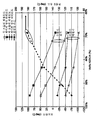
도 1은 20 ℃ H2SO4(98wt%)가 20 ℃ 물 또는 20 ℃ H2O2(30wt%)와 비이커에서 급속히 혼합될 때 얻어지는 온도를 보여준다. 약 100%와 57% 사이의 H2SO4 부피분율인 영역 A에서, H2SO4/물 혼합물은 물의 양이 증가할수록 온도가 증가한다. 약 56%와 36% 사이 분율인 영역 B에서, H2SO4/물 혼합물은 물의 양이 증가할수록 온도가 약간 감소한다. 약 35%와 10% 사이 분율인 영역 C에서, 혼합물의 온도는 물의 양이 증가할수록 급격히 감소한다. H2O2가 H2SO4 과 혼합될 때의 온도 프로필은 동일한 경향을 따르나 최대온도가 약간 낮다. 약 43부피% H2O2 와 57% H2SO4 의 H2SO4/물 혼합물에 대해서 약 110℃(최종온도 130℃)의 최대온도가 얻어진다. 또한 물 : H2SO4 혼합물의 H2SO4에 대한 H2O 의 몰비는 상부 축에 도시되어 있다. 영역 A와 영역 B 사이의 경계는 약 2:1의 물:H2SO4이며 B와 C 사이의 경계는 약 5:1이다.1 shows the temperature obtained when 20 ° C. H 2 SO 4 (98 wt%) is rapidly mixed in 20 ° C. water or 20 ° C. H 2 O 2 (30 wt%) in a beaker. Between about 100% and 57% H 2 SO 4 In region A, the volume fraction, the H 2 SO 4 / water mixture increases in temperature with increasing amount of water. In zone B, which is a fraction between about 56% and 36%, the H 2 SO 4 / water mixture decreases slightly in temperature as the amount of water increases. In zone C, which is a fraction between about 35% and 10%, the temperature of the mixture decreases rapidly as the amount of water increases. H 2 O 2 is H 2 SO 4 When mixed with, the temperature profile follows the same trend but with a slightly lower maximum temperature. About 43% by volume H 2 O 2 A maximum temperature of about 110 ° C. (
도 2는 도 1의 물이 부가된 곡선으로부터 얻어진 것이다. 이것은 용액 내 H2SO4 분율의 함수로서 물의 퍼센트 증가에 따른 온도증가를 보여준다. 100%에서 37%까지의 H2SO4분율에서 dT/dWater의 거의 선형적 증가를 보여준다. 이론에 속박되지 않는다면, 용액의 온도증가(혼합열)는 물분자가 각 황산분자 둘레에 배열될 때의 수화열에 의한 것이라고 생각된다. 본 발명에서, 물과 황산분자 사이의 강한 인력은, 황산조성물이 물의 끓는 점 이상에 있을 때조차도, 대기의 수증기를 황산조 성물로 끌어당기는 건조작용(desiccant action)을 유도한다. 약 55부피% 황산에서, 수화열은 부가된 물의 열부하(thermal load)에 의해 균형이 맞춰지며 부가적으로 부가된 물은 혼합물에 대해 냉각효과를 갖는다. 약 37부피% H2SO4에서, H2SO4의 수화는 종료되는 것으로 나타난다. 도 1과 도 2의 상부 x축에는 용액의 물:H2SO4의 몰비를 보여준다. 수화는 H2SO4 1몰에 대해 약 5몰의 물이 존재할 때 종료되는 것으로 나타난다. FIG. 2 is obtained from the curve to which the water of FIG. 1 is added. This shows the temperature increase with increasing percentage of water as a function of the H 2 SO 4 fraction in solution. It shows a nearly linear increase in dT / dWater at H 2 SO 4 fractions from 100% to 37%. Without being bound by theory, it is believed that the temperature increase (mixing heat) of the solution is due to the heat of hydration when the water molecules are arranged around each sulfuric acid molecule. In the present invention, the strong attraction between water and sulfuric acid molecules induces a desiccant action that attracts atmospheric water vapor to the sulfuric acid composition even when the sulfuric acid composition is above the boiling point of the water. At about 55 vol% sulfuric acid, the heat of hydration is balanced by the thermal load of the added water and the additionally added water has a cooling effect on the mixture. At about 37% by volume H 2 SO 4 , the hydration of H 2 SO 4 appears to end. The upper x-axis of FIGS. 1 and 2 shows the molar ratio of water: H 2 SO 4 of the solution. Hydration is H 2 SO 4 It appears to terminate when about 5 moles of water per mole are present.
도 1과 달리, 본 발명은 조성물로의 수증기 응축에 의해 물을 황산 조성물에 첨가한다. 이는 황산과 물의 혼합열뿐만 아니라 물이 황산 조성물에 응축될 때 회수되는 물의 기화열에 의해 조성물을 가열하는 결과가 된다. 액상의 물을 황산에 첨가하는 경우에 비해, 수증기의 기화열에 의한 열적 기여도는 주어진 양의 희석에 대해서 더 큰 온도증가를 허용한다. Unlike FIG. 1, the present invention adds water to the sulfuric acid composition by steam condensation into the composition. This results in heating the composition not only by the heat of mixing sulfuric acid and water, but also by the heat of vaporization of the water recovered when the water is condensed in the sulfuric acid composition. Compared to the addition of liquid water to sulfuric acid, the thermal contribution by the heat of vaporization of the water vapor allows for a larger temperature increase for a given amount of dilution.
도 3A와 3B는 본 발명의 공정을 실행하는데 유용한 장비의 일 예를 보여준다. 도 3A는 화학물질의 혼합 매니폴드(90), 순환 탱크(50) 및 공정 보울(bowl)(12)을 포함하는 주요 시스템 성분을 보여주는 배치 스프레이 공정기(10)의 개략도이다. 공정기(10)는 미네소타주 차스카 소재의 FSI International, Inc로부터 구매할 수 있는 MECURY® 또는 ZETA® 스프레이 공정기에 포함된 바와 같은 스프레이 공정장치의 개략도이다. 공정기(10)는 일반적으로 공정 챔버(16)를 형성하는 보울(12)과 뚜껑(14)을 포함한다. 웨이퍼와 같은 물체(18)가 캐리어(20)(예를 들면, TEFLON® 카세트)에 위치되며, 캐리어는 턴테이블 기둥(미도시)에 의해 회전하는 턴테이블(22) 상에 유지된다. 턴테이블(22)은 모터-피동 축(24)에 연결된다. 물 또는 질소가 공급라인(들)(32)로부터 공급되며 턴테이블 기둥(미도시)을 통해 공정 챔버(16) 내로 분배된다. 하나 이상의 화학약품들이 또한 공급라인(들)(34)로부터 공급되며 웨이퍼(18) 직상으로의 및/또는 중앙 스프레이 기둥(36)을 통해 턴테이블(22) 직상으로의 또는 라인(들)(38)을 경유하여 측 스프레이 기둥(40)을 통해 웨이퍼 위의 공정 챔버(16) 내로 분배된다. 3A and 3B show examples of equipment useful for carrying out the process of the present invention. 3A is a schematic diagram of a
예를 들면, 공급 라인(34)은 화학물질의 순환 시스템(49)에 유체유동가능하게 연결된다. 이 순환 시스템은 화학물질의 공급라인(67,68)을 포함할 수 있다. 화학물질의 공급라인(67)은 필터(64,66), 펌프(62)를 포함할 수 있으며, 순환공급 탱크(50)에 유체유동가능하게 연결된다. 이 공급 탱크에는 순환 드레인(54)으로부터의 공정 화학약품 및 새로운 화학약품 보충물(chemical makeup)(52)이 공급된다. 질소 블랭킷(56)이 탱크(50)의 상부공간에 사용될 수 있다. 탱크(50) 내 공정 화학물질의 온도를 제어하기 위해 탱크(50)는 가열 코일(58), 냉각 코일(600 및 온도 프로브(41)가 포함될 수 있다. 화학물질 공급 라인(68)은, 예를 들면, 질소 및 DI 세정수를 공급할 수 있다. 공정 챔버(16)로 화학물질의 공급 후에, 미사용 화학물질은 드레인(70)으로 들어가서 드레인 매니폴드(71)로 유입될 수 있다. 화학물질은 드레인 매니폴드로부터 순환 드레인(54), 배출관(72), DI 드레인(74), 보조부(76,78,80, 및 82)와 같은 여러 출구로 공급된다.For example, the supply line 34 is fluidly connected to the
공급 라인(34) 역시 새로운 화학물질의 혼합 매니폴드(90)에 유체유동가능하게 연결된다. 이 매니폴드에서, 라인(91-94)으로부터의 새로운 화학물질의 제어된 유동이 혼합되어 소정의 혼합물(blend)을 형성하고 라인(98,34)을 경유하여 중앙 스프레이 기둥(36) 또는 라인(98,38)을 경유하여 측 스프레이 기둥(40)으로 보내진다. 선택에 따라서, 화학물질의 혼합물은 라인(98)의 인-라인 적외선 히터(히터는 미도시)에 의해 가열될 수 있다. 또는, 하나 이상의 공급 화학물질이 하나 이상의 라인(91-94)에 위치된 적외선 히터에 의해 가열될 수 있다. Supply line 34 is also fluidly connected to mixing
공정기(10)의 구성 및 사용은 미국 특허 5,971,368;6,235,641;6,274,506 및 6,648,307호 뿐만 아니라 Benson 등이 회전 유니온, 유체 공급 시스템 및 관련 방법이라는 명칭으로 2004년 3월 12일 출원되어 출원계속중인 미국특허출원 10/799,250호에 더욱 자세히 기재되어 있으며, 이 계속중인 출원은 그 전 내용이 참조로 여기에 포함되어 진다.The construction and use of the
도 3B는 본 발명에 따라서 공정기(10)를 사용하는 작업모드의 일 예를 보여준다. 황산용액 조성물(42)은 중앙 스프레이 기둥(36) 및/또는 측 스프레이 기둥(40)(미도시)으로부터 유기물질로 피복된 기판을 실질적으로 균일하게 코팅하기에 유효한 양으로 기판 위에 분배된다. 이 실질적으로 균일한 코팅은, 예를 들면, 동일한 장치를 사용하여, 약 5:1 이하의 물/황산 몰비를 갖는 황산용액 조성물이 표면에 가해질 때 표면에 실질적으로 균일하게 코팅되는 표면을 제공하도록 예비처리 액체로 예비처리됨으로써 용이하게 얻어질 수 있다. 언급한 바와 같이, 예비처리 조성물은, 예를 들면, 약 5:1 이하의 물/황산 몰비를 갖는 후속(또는 계속되는) 황산용액 조성물을 가하여 기판을 실질적으로 균일하게 코팅하도록 기판의 표면특성을 개질시키기 위해 사전에 가하는 황산용액 조성물일 수 있다. 선택에 따라서, 기판 표면특성을 원하는 바대로 개질하도록 작용하는 용제 또는 계면활성제와 같은 다른 표면 개질 성분이 예비처리 액체로 사용될 수 있다. 부가적인 성분들이 예비처리 용액의 화학적 변형을 제공하도록 첨가될 수 있다. 예를 들면, 소량의 산이 예비처리 수용액에 첨가될 수 있다. 3B shows an example of a work mode using a
황산용액 조성물(42)이 분배된 후(또는 분배되는 동안, 또는 분배 전에), 열수(熱水)(44)가 턴테이블(22)로 분배된다. 열수(44) 일부의 기화는 챔버 분위기의 수증기 양(습도)을 증가시킨다. 웨이퍼(18)는 제거될 유기물질로 피복되어 있다. 바람직한 실시예에서, 유기물질은 감광제 물질이다. 제거하기 힘든 유기물질은 이전의 웨이퍼 공정단계 중에 열에 노출됨으로써 구워진(baked) 감광제를 포함한다. 특히 제거하기 힘든 유기물질은 이전의 공정단계 중에 심하게 이온주입된 감광제이다. 본 발명의 방법은 심하게 이온주입된 감광제 물질의 제거에 특히 그리고 놀랍도록 유효하다.After the sulfuric
황산용액 조성물(42)은 약 5:1 이하의 물/황산 몰비를 갖는다. 이처럼, 황산용액 조성물은 물의 양에 의해 제한된다. 일 실시예에서, 황산용액 조성물은, 여기서 보다 상세히 논의된 바와 같이, 황산으로 후속으로 첨가된 수증기의 조정에 실질적으로 간섭하지 않는 용제를 포함할 수 있다. 바람직한 이러한 용제는,불소계 액체와 같이, 처리될 기판(예를 들면, 웨이퍼)에 대해 불활성이다. 이러한 불활성 용제의 일 예는 미네소타주의 세인트 폴에 있는 3M으로부터 구매할 수 있는 Fluorinert® 용제를 포함할 수 있다. 상기 몰비는 물/황산 몰비를 말하는 것이며 용제/황산 몰비를 말하는 것은 아니다. 이는 황산으로 후속으로 첨가된 수증기의 조정에 실질적으로 간섭하지 않는 용제는 본 발명 실시예의 이 비에 포함되는 인자가 아님을 강조한다. The sulfuric
*보다 바람직하게, 황산용액 조성물은 고도로 농축된다. 바람직하게, 황산용액 조성물은 적어도 약 80부피%, 보다 바람직하게는 적어도 약 90부피%, 가장 바람직하게는 적어도 약 94부피%의 황산용액 조성물로 분배된다. 도 1 및 2에 도시된 바와 같이, 고농도 H2SO4 은 H2SO4 조성물 내로 응축된 단위 수증기당 가장 큰 온도증가로 이어진다. More preferably, the sulfuric acid solution composition is highly concentrated. Preferably, the sulfuric acid solution composition is partitioned into at least about 80 volume%, more preferably at least about 90 volume%, most preferably at least about 94 volume% sulfuric acid solution composition. As shown in Figures 1 and 2, high concentration H 2 SO 4 Silver H 2 SO 4 This leads to the largest temperature increase per unit water vapor condensed into the composition.
본 발명의 일 실시예에서, 황산용액 조성물(42)은 과산화 수소를 포함한다. 과산화 수소는 유기 종을 CO2 와 물로 분해하는데 도움을 주는 산화제 역할을 한다. 편리하게, 과산화 수소는 약 5:1 이하의 물/황산 몰비를 갖는 황산용액 조성물을 제공하도록 농축된 황산으로 혼합된 물을 포함하는 용액에 제공된다. 유리하게, 물을 포함하는 과산화 수소 용액으로 농축 황산을 혼합시키면, 발열반응에 의해 열을 발생시켜서 과산화 수소를 포함하는 황산용액 조성물은 조성물을 가열하기 위한 열원으로부터의 에너지를 적게 사용하면서 상승된 온도로 제공될 수 있다. 통상적으로 이 발열반응은 조성물에 대한 상당한 열원이 된다. 그러나, 본 발명에서 황산 조성물과 수증기 사이의 반응은 원하는 열을 제공하며, 수계(water-based) 과산화 수소의 과도한 첨가는 황산-증기 반응을 억제할 수 있다. 따라서, 여기서 언급된 바와 같이,농축 황산 조성물에서의 수증기 효과를 안다면, 당업자는 유기물을 산화시키기에 충분한 반응체를 공급하면서 동시에 H2SO4 - 수증기 반응에 의해 발생된 열을 최적화하도록 H2O2 농도를 조정할 수 있을 것이다.In one embodiment of the present invention, the sulfuric
본 발명에서, 산화제는 황산용액 조성물의 분배 전, 동안 또는 후에 처리 챔버 내로 도입될 수 있다. 예를 들면, 과산화 수소는 처리 챔버 내로 황산용액 조성물의 도입 전에 또는 황산용액 조성물의 분배 중에 또는 분배 후에 황산용액 조성물과 혼합될 수 있다. 농축 황산용액과 과산화 수소의 혼합은 정지 혼합기 또는 동적 혼합 기술을 사용하여 달성될 수 있으며, 또는 단지 하나의 용액을 다른 용액과 접촉시켜서 확산에 의해 혼합이 얻어질 수도 있다. 오존과 같은 다른 성분이 유사하게 황산용액 조성물에 포함되질 수 있다. 오존과 같은 무수 산화제는 황산 조성물을 희석시키지 않기 때문에 과산화 수소보다 좋을 수 있다. 예를 들면, 과산화 수소 이외의 산화제가 황산-수증기 공정에 사용될 수 있다. 예를 들면, 오존, 질산, 크로메이트 이온(Cr+6) 또는 세륨 이온(Ce+4)이 여기서 설명된 바와 같은 공정에 도입될 수 있다. 특히 이들 종들이 무수형태로 황산에 첨가되어서 황산이 상대적으로 희석된 채로 유지될 수 있다. 또한 다른 산화제들이 사용될 수 있다.In the present invention, the oxidant may be introduced into the processing chamber before, during or after dispensing the sulfuric acid solution composition. For example, hydrogen peroxide may be mixed with the sulfuric acid solution composition prior to introduction of the sulfuric acid solution composition into the processing chamber or during or after dispensing the sulfuric acid solution composition. Mixing of concentrated sulfuric acid solution and hydrogen peroxide may be accomplished using a static mixer or dynamic mixing technique, or mixing may be obtained by diffusion by contacting only one solution with another solution. Other components, such as ozone, may similarly be included in the sulfuric acid solution composition. Anhydrous oxidants such as ozone may be better than hydrogen peroxide because they do not dilute the sulfuric acid composition. For example, oxidants other than hydrogen peroxide may be used in the sulfuric acid-steam process. For example, ozone, nitric acid, chromate ions (Cr +6 ) or cerium ions (Ce +4 ) can be introduced into the process as described herein. In particular, these species can be added to the sulfuric acid in anhydrous form so that the sulfuric acid remains relatively diluted. Other oxidants may also be used.
바람직하게, 황산용액 조성물은 적어도 약 90℃, 보다 바람직하게는 약 90℃에서 약 150℃의 온도로 분배된다. 다른 실시예에서, 황산용액 조성물은 약 95℃에서 약 120℃ 온도에서 분배된다. 다른 실시예에서, 황산용액 조성물은 수증기에 노 출 전 약 130℃, 보다 바람직하게는 약 130℃에서 약 200℃의 온도에서 분배된다. 황산용액 조성물(42)의 도입은 황산 화학물질로 웨이퍼 표면을 적신다. 바람직하게, 황산용액 조성물(42)은 웨이퍼(18)에 코팅된 유기물질을 제거하기에 충분한 황산 기능성(functionality)을 제공하는 양으로 웨이퍼에 가해진다. 바람직하게, 황산용액 조성물은 적어도 역 5 마이크론, 보다 바람직하게는 적어도 약 10 마이크론의 두께로 유기물질 피복 기판에 분배된다. 본 발명의 일 실시예에서, 황산용액 조성물은 약 10 마이크론에서 약 140 마이크론, 보다 바람직하게는 약 10 마이크론에서 약 60 마이크론의 두께로 유기물질 피복 기판에 분배된다. Preferably, the sulfuric acid solution composition is partitioned at a temperature of at least about 90 ° C, more preferably from about 90 ° C to about 150 ° C. In another embodiment, the sulfuric acid solution composition is dispensed at a temperature of about 95 ° C to about 120 ° C. In another embodiment, the sulfuric acid solution composition is partitioned into steam at a temperature of about 130 ° C., more preferably about 130 ° C. to about 200 ° C., prior to exposure. Introduction of the sulfuric
일 실시예에서, 웨이퍼(18)는 약 20℃에서 약 60℃의 온도와 같이 물의 끓는 점 이하의 온도에서 제공된다. 웨이퍼(18)는 바람직하게 황산용액 조성물의 분배 전, 동안 또는 후에 적어도 약 90℃의 온도로 가열된다. 보다 바람직하게, 웨이퍼(18)는 약 90℃에서 약 150℃의 온도로 가열된다. 다른 실시예에서, 웨이퍼는 약 95℃에서 약 120℃의 온도로 가열된다. 이러한 가열은, 예를 들면, 방사열을 이용한 챔버의 가열, 웨이퍼로의 뜨거운 물이나 다른 용액의 도입 및 농축 황산용액 조성물을 가하기 전에 가열된 용액의 실질적인 제거, 챔버로의 가열기체 도입 등에 의해 실행될 수 있다. 용액이 웨이퍼와 직접 접촉하여 웨이퍼를 가열하도록 사용된다면, 충분한 양의 용액이 농축된 황산용액 조성물의 도입 전에 웨이퍼로부터 제거되어서 농축된 황산용액 조성물이 수증기에 노출되기 전에 황산용액 조성물이 원하는 수준의 황산농도를 유지토록 하여야 한다. In one embodiment,
본 발명의 일 실시예에서, 웨이퍼는 하나 이상의 웨이퍼를 가열된 액체 욕으 로 침하시키고, 신속하게 욕의 내용물을 배출시키고(예를 들면, "퀵덤프(quickdump)공정) 그리고 후술하는 바와 같은 나머지 처리단계를 실행함으로써 예열될 수 있다. 예를 들면, 욕의 용액은 DI 수, 황산을 포함하는 DI 수, 황산/과산화 수소 혼합물, (플루오로카본 과 같은)불활성 유체, 황산/오존 혼합물 등일 수 있다. 이 실시예는 웨이퍼를 보다 효율적으로 가열함으로써 처리공정의 수율을 증가시키는 상당한 장점을 제공한다. 본 실시예를 채용하기 위해 사용될 수 있는 특히 적당한 공정시스템의 일예는 미네소타주 차스카 소재의 FSI International, Inc로부터 구매할 수 있는 Magellan® 시스템이다.In one embodiment of the present invention, the wafers sink one or more wafers into a heated liquid bath, quickly drain the contents of the bath (e.g., a "quickdump process") and the remaining processing as described below. For example, the bath solution may be DI water, DI water including sulfuric acid, sulfuric acid / hydrogen peroxide mixtures, inert fluids (such as fluorocarbons), sulfuric acid / ozone mixtures, and the like. This example provides a significant advantage of increasing the throughput of the process by heating the wafer more efficiently An example of a particularly suitable process system that can be used to employ this embodiment is FSI International, Chaska Minnesota. Magellan ® system, available from Inc.
수증기는 임의의 적당한 방법으로 챔버로 도입된다. 도 3B에 도시된 바와 같이, 가열된 DI 수(44)가 중앙 스프레이 기둥(36)의 하부(46)로부터 회전하는 턴테이블(22)로 뿌려진다. 이 "뿌림(splashdown)" 과정에서 수증기가 발생된다. 또는, 처리 챔버 내에서 물을 가열 및/또는 교반과 같은 다른 적당한 수증기 발생기술에 의해 처리 챔버 내부에 수증기를 발생시킬 수 있다. Water vapor is introduced into the chamber in any suitable way. As shown in FIG. 3B,
또 다른 방법으로, 처리 챔버 외부에서 수증기를 발생시켜고 이를 처리 챔버 내로 도입할 수 있다. 예를 들면, 외부에서 생성된 수증기는 가스 또는 혼합가스의 성분으로 챔버로 공급될 수 있다. 일 실시예로, 물(바람직하게는 열수) 기둥을 통해 가스(예를 들면 N2) 기포를 통과시킴으로써 수증기를 발생시킬 수 있다. 또 다른 실시예로, 가스를 소정의 물 표면 위로 통과시킨다. 또 다른 실시예로, 화학공학에서 흔히 사용되는 바와 같은 용수 충전탑(irrigated packed column)을 통해 가스를 통과시킬 수 있다. 또 다른 실시예로, 물을 끓임으로써 실질적으로 순수한 수증기를 발생시킬 수 있다. 이들 다양한 방법을 통해 얻어진 가스 생성물은 더욱 가열될 수 있다. 또한 다른 실시예들도 가능하다. Alternatively, water vapor can be generated outside the processing chamber and introduced into the processing chamber. For example, externally generated water vapor may be supplied to the chamber as a component of the gas or mixed gas. In one embodiment, water vapor may be generated by passing a gas (eg N 2 ) bubble through a water (preferably hydrothermal) column. In another embodiment, the gas is passed over a surface of the water. In another embodiment, the gas can be passed through an irrigated packed column as is commonly used in chemical engineering. In another embodiment, boil water can generate substantially pure water vapor. Gas products obtained through these various methods can be further heated. Other embodiments are also possible.
바람직하게, 수증기는 약 70℃에서 약 150℃의 수증기 온도에서 웨이퍼에 노출되도록 도입된다. 보다 바람직하게, 수증기는 약 80℃에서 약 110℃의 수증기 온도에서 웨이퍼에 노출되도록 도입된다. 특히 바람직한 실시예에서, 수증기는 약 85℃에서 약 98℃의 수증기 온도에서 웨이퍼에 노출되도록 도입된다. 이 실시예의 경우, 수증기는 전술한 "뿌림"과정으로 용이하게 발생할 수 있기 때문에 유리하다. 수증기는 기화점에 있지 않기 때문에, 바람직하지 않은 스패터링(spattering)의 발생 없이 수증기의 도입제어를 용이하게 달성할 수 있다. 다른 유리한 실시예로, 수증기는 약 100℃의 수증기 온도로 노출되도록 도입된다. 이 실시예는 종래의 스팀 형성장치에 의해 처리 용기 외부 또는 내부에서 스팀을 형성하도록 종래의 조건하에서 물을 끓임으로써 상대적으로 용이하게 실행될 수 있다. Preferably, water vapor is introduced to expose the wafer at a water vapor temperature of about 70 ° C. to about 150 ° C. More preferably, water vapor is introduced to expose the wafer at a water vapor temperature of about 80 ° C. to about 110 ° C. In a particularly preferred embodiment, water vapor is introduced to expose the wafer at a water vapor temperature of about 85 ° C. to about 98 ° C. In the case of this embodiment, water vapor is advantageous because it can be easily generated by the above-described "sprinkling" process. Since the steam is not at the vaporization point, it is easy to achieve control of the introduction of the steam without the occurrence of undesirable spattering. In another advantageous embodiment, water vapor is introduced to be exposed to a water vapor temperature of about 100 ° C. This embodiment can be performed relatively easily by boiling water under conventional conditions to form steam outside or inside the processing vessel by a conventional steam forming apparatus.
또 다른 실시예에서, 수증기는 수증기에 노출되기 전의 황산용액 조성물의 온도보다 높은 온도로 제공된다. 이 실시예는 전술한 바와 같이 수증기의 황산용액 조성물로 응축시 에너지 전달뿐만 아니라 직접적인 열전달에 의해 황산용액 조성물을 직접가열하는 장점을 제공한다. 일 실시예에서, 수증기는 이러한 목적을 위해 약 150℃보다 높은 온도로 제공된다. In another embodiment, the water vapor is provided at a temperature higher than the temperature of the sulfuric acid solution composition prior to exposure to water vapor. This embodiment provides the advantage of directly heating the sulfuric acid solution composition by direct heat transfer as well as energy transfer upon condensation with the sulfuric acid solution composition of water vapor as described above. In one embodiment, water vapor is provided at a temperature above about 150 ° C. for this purpose.
선택에 따라, 수증기는 원하는 바에 따라 과산화 수소 또는 오존과 같은 다른 성분을 부가적으로 포함할 수 있다. Optionally, the water vapor may additionally include other components, such as hydrogen peroxide or ozone, as desired.
수증기는 수증기에 노출되기 전의 황산용액 조성물의 온도 이상으로, 및 바람직하게는 또한 수증기의 온도 이상으로 황산용액 조성물의 온도를 증가시키는데 유효한 양으로 챔버 내로 도입된다. 본 발명의 일 실시예에서, 황산용액 조성물은 기판표면상의 황산용액 조성물의 온도를 (i)수증기에 노출 전의 황산용액 조성물의 기판상의 온도 및 (ii)수증기의 온도 이상으로 증가시키는데 유효한 양으로 수증기에 노출된다. 놀랍게도, 황산용액 조성물의 온도가 물의 끓는점 근처 또는 그 이상일 때조차도 수증기는 여전히 황산용액 조성물의 온도를 증가시키는 방식으로 황산용액 조성물과 연관되며, 이렇게 하여 황산용액 조성물의 온도증가로 인한 유기물질 제거효과를 증가시킨다. Water vapor is introduced into the chamber in an amount effective to increase the temperature of the sulfuric acid solution composition above the temperature of the sulfuric acid solution composition before exposure to water vapor, and preferably also above the temperature of water vapor. In one embodiment of the present invention, the sulfuric acid solution composition comprises water vapor in an amount effective to increase the temperature of the sulfuric acid solution composition on the substrate surface above (i) the temperature on the substrate of the sulfuric acid solution composition prior to exposure to water vapor and (ii) the temperature of water vapor. Is exposed to. Surprisingly, even when the temperature of the sulfuric acid solution composition is near or above the boiling point of water, the water vapor is still associated with the sulfuric acid solution composition in such a way as to increase the temperature of the sulfuric acid solution composition, thereby removing the organic substances due to the temperature increase of the sulfuric acid solution composition. To increase.
바람직하게, 적어도 약 20℃, 보다 바람직하게는 적어도 약 40℃, 보다 바람직하게는 적어도 약 60℃까지 황산용액 조성물의 온도를 증가시키도록 충분한 황산용액 조성물 및 수증기가 존재하며 혼합된다. 이는 황산용액 조성물이 이 황산용액 조성물의 온도에 가까운 온도를 유지하기 위해 상당한 에너지를 흡수하며 열 싱크로서 역할을 하는 웨이퍼 상에 위치되기 때문에 특히 중요하다. 기판표면상의 황산용액 조성물의 온도는 적당한 측정방법으로 결정될 수 있다. 본 발명의 목적을 위해, 턴테이블(22)상의 웨이퍼 캐리어 회전중에 처리용기 벽에 투사된(cast) 액의 온도를 측정하기 위해 온도 프로브(41)를 사용하여 적당한 온도 근사치를 얻을 수 있다. 이러한 측정을 실행하기 위해, 온도 프로브는 처리용기 내에 위치될 수 있다. 일 실시예에서, 변색 온도지시 물질이 처리용기에서 얻어지는 최대온도를 지시하기 위해 사용될 수 있다.Preferably, sufficient sulfuric acid solution composition and water vapor are present and mixed to increase the temperature of the sulfuric acid solution composition to at least about 20 ° C, more preferably at least about 40 ° C, more preferably at least about 60 ° C. This is particularly important because the sulfuric acid solution composition is placed on a wafer that absorbs significant energy and serves as a heat sink to maintain a temperature close to that of the sulfuric acid solution composition. The temperature of the sulfuric acid solution composition on the substrate surface can be determined by a suitable measuring method. For the purposes of the present invention, an appropriate temperature approximation can be obtained using the
수증기에 대한 황산용액 조성물의 노출은 유기물질로 피복된 기판상에 위치될 때 황산용액 조성물의 온도를 증가시키는데 효과적인 시간에 수행될 수 있다. 일 실시예에서, 수증기는 황산용액 조성물의 분배중에 처리챔버 내로 도입된다. 이 실시예에서, 황산용액 조성물의 온도는 기판과 조성물의 접촉 전에조차도 증가하기 시작할 수 있다는 것이 인식될 것이다. 이 실시예에서, 전술한 바와 같이 수증기에 노출시 황산용액 조성물의 온도증가는 분배시의 황산용액 조성물의 온도와 수증기에 노출 후의 황산용액 조성물의 최대온도 사이의 차이로 취해질 수 있다.Exposure of the sulfuric acid solution composition to water vapor can be performed at an effective time to increase the temperature of the sulfuric acid solution composition when placed on a substrate coated with an organic material. In one embodiment, water vapor is introduced into the treatment chamber during dispensing of the sulfuric acid solution composition. In this embodiment, it will be appreciated that the temperature of the sulfuric acid solution composition may begin to increase even before contact of the composition with the substrate. In this embodiment, as described above, the temperature increase of the sulfuric acid solution composition upon exposure to water vapor can be taken as the difference between the temperature of the sulfuric acid solution composition upon distribution and the maximum temperature of the sulfuric acid solution composition after exposure to water vapor.
본 발명의 다른 실시예에서, 황산용액 조성물은 연속적인 스트림이 아니라 복수의 불연속적인 펄스로 제공된다. 이들 펄스는 짧고(예를 들면, 약 3-10초의 길이로), 고속(예를 들면, 약 2-8 lpm의 유속)인 것이 바람직하다. 액체 유동없이 펄스간 약 5 내지 20초의 시간주기가 바람직하다. 펄스화된 액체 유동으로 작업시, 수증기는 펄스 동안에만 도입되도록 선택되어서 본 공정 중에 챔버로부터 유출되는 수증기의 양을 감소시킨다. 마찬가지로, 기판에 있는 동안 황산용액 조성물의 가열을 강화하도록 펄스들 사이에 또는 기판과 조성물의 접촉 전에 황산용액 조성물의 온도증가를 향상시키기 위해 수증기는 선택에 따라서 펄스 동안에 도입될 수 있다. In another embodiment of the present invention, the sulfuric acid solution composition is provided in a plurality of discrete pulses rather than in a continuous stream. These pulses are preferably short (eg, about 3-10 seconds long) and high speed (eg, about 2-8 lpm flow rate). A time period of about 5-20 seconds between pulses without liquid flow is preferred. When working with a pulsed liquid flow, water vapor is chosen to be introduced only during the pulse, reducing the amount of water vapor exiting the chamber during this process. Likewise, water vapor may optionally be introduced during the pulse to enhance the temperature increase of the sulfuric acid solution composition between pulses or prior to contact of the composition with the substrate to enhance heating of the sulfuric acid solution composition while in the substrate.
또 다른 실시예에서, 황산용액 조성물의 분배는 수증기의 도입 전에 중단된다. 이 실시예에서, 기판에는 상대적으로 정지상태인 황산용액 조성물의 코팅이 제공된다. 선택에 따라서, 기판의 회전은 황산용액 조성물의 분배 동안 및/또는 후에, 그리고 수증기에 대한 황산용액 조성물의 노출 동안 약 20rpm 이하의 속도로 저속화되거나 정지된다. 이 공정은 기판상에 있는 황산용액 조성물 코팅(또는 "풀 링(pooling)")의 유지를 향상시기기 위해 실행된다. 이론에 속박되지 않는다면, 황산용액 조성물은 특히 수증기에 대한 황산용액 조성물의 노출 동안 벌크운동(bulk motion)을 거의 보이지 않기 때문에, 조성물은 기판의 모든 지점에서 상당한 속도로 기판표면의 바람직하지 않은 물질을 용해 및/또는 제거하는 경향이 있다고 여겨진다. 이렇게 향상된 균일성은 수증기에 대한 황산용액 조성물의 균일한 노출에 기인한 것일 수 있다. 부가적으로 또는 다른 방법으로, 바람직하지 않은 물질의 제거(특히, SiO2의 제거)로 인한 향상된 균일성은 코팅의 모든 지점에서 용해된 바람직하지않은 물질에 의한 황산용액 조성물의 균일한 포화도에 기인한 것일 수 있다. 황산용액 조성물의 분배는 유동속도, 분배시간, 및 원심력에 의한 황산용액 조성물의 제거속도 변화에 의한 황산용액 조성물 층의 두께를 변경시킴으로써 더욱 변화될 수 있다. 또한, 바람직하지 않은 물질제거는 수증기단계 후에 소모된 황산용액 조성물의 제거(ramping off), 새로운 황산용액 조성물 층의 도입, 및 챔버 내로 수증기의 재도입에 의해 강화될 수 있다. In another embodiment, the dispensing of the sulfuric acid solution composition is stopped before the introduction of water vapor. In this embodiment, the substrate is provided with a coating of a relatively stationary sulfuric acid solution composition. Optionally, the rotation of the substrate is slowed down or stopped at a rate of about 20 rpm or less during and / or after dispensing the sulfuric acid solution composition and during exposure of the sulfuric acid solution composition to water vapor. This process is carried out to improve the retention of the sulfuric acid solution composition coating (or "pooling") on the substrate. Unless bound by theory, the sulfuric acid solution composition shows little bulk motion, especially during the exposure of the sulfuric acid solution composition to water vapor, so that the composition is able to remove undesirable substances on the substrate surface at a significant rate at all points of the substrate. It is believed that there is a tendency to dissolve and / or remove. This improved uniformity may be due to the uniform exposure of the sulfuric acid solution composition to water vapor. Additionally or alternatively, the improved uniformity due to the removal of undesirable substances (particularly the removal of SiO 2 ) is due to the uniform saturation of the sulfuric acid solution composition with the undesirable substances dissolved at all points of the coating. It may be. The distribution of the sulfuric acid solution composition can be further changed by varying the thickness of the sulfuric acid solution composition layer by varying the flow rate, distribution time, and removal rate of the sulfuric acid solution composition by centrifugal force. Undesired material removal can also be enhanced by ramping off spent sulfuric acid solution composition after the steaming step, introducing a new layer of sulfuric acid solution composition, and reintroducing water vapor into the chamber.
위에서 언급한 바와 같이, 황산용액 조성물(42)은 스프레이 기둥(36 및 또는 40)으로부터 웨이퍼(18)로 분배된다. 웨이퍼 처리장치의 일부 구성에서, 스프레이 기둥의 위치 및 기둥으로부터의 유체유동 방향은 본 공정의 성능에 영향을 주는 것으로 나타났다. 고정된 스프레이 기둥을 갖는 웨이퍼 처리장치에 있어서, 분배된 유동은 웨이퍼의 일부분에 액체의 고농축으로 이어지도록 침적되는 경향이 있다. 예를 들면, 중앙 스프레이 기둥(36)으로부터 분배된 액체는 중앙 스프레이 기둥 근 방에 고농축으로 기판상에 침적되기 쉽다. 또한, 턴테이블(22)의 일부 방향에서, 중앙 스프레이 기둥으로부터 온 액체의 상당량이 웨이퍼들 사이를 통과하여 낭비될 수 있다. 바람직하게, 측 스프레이 기둥(side-bowl spray post)(SBSP)(40)을 사용하여 월등한 침적효율 및 균일성이 얻어질 수 있다. 그러나, 막바로 턴테이블의 회전축을 향해, 챔버면(the face of the chamber)에 수직한 SBPB에 의해 분배된 스프레이는 역시 중앙 스프레이 기둥 근방에 과도하게 액을 침적시키는 경향이 있다. 또한 이 수직 스프레이는 턴테이블의 일부 방향에서 웨이퍼들 사이를 통과하는 액을 낭비한다. 뛰어난 침적패턴은 스프레이 기둥( 및 특히 SBSP)으로부터 나오는 액체 스프레이를 챔버 주면(the major surface of the chamber)으로부터 수직한 선에 대해 경사지게 하고 및/또는 턴테이블의 중심으로부터 이격되게 함으로써 얻어질 수 있다. 경사진 스프레이는 중앙 스프레이 기둥 근방에 덜 "집중된(focused)" 침적으로 이어지지만, 어떠한 경사도 균일한 피복을 위해 충분하지 않다. 본 발명의 실시예에서 스프레이의 각도는 정지적이다. 본 발명의 다른 실시예에서, 기판(들)을 지지하는 턴테이블은 기판표면상으로 황산용액 조성물의 분배 동안 회전되며, 황산용액 조성물은 소사(掃射)운동(sweeping motion)으로 턴테이블에 대해 여러 각도에서 조성물을 스프레이함으로써 분배된다. 이 실시예에서, 황산용액 조성물의 단일분배동안 스프레이 각도는 변경된다. 이 실시예에서, 복수의 액 분배가 처리 사이클로 실시되는 때, 황산용액 조성물의 일 분배에서 다음 분배까지 스프레이 각도는 변경된다.As mentioned above, the sulfuric
황산용액 조성물의 스프레이 각도(또는 "소사(sweeping)")는 스프레이의 초 점들의 위치를 변경시켜서 보다 균일한 액 침적으로 이어진다. 또한 웨이퍼-캐리어 시스템에 대한 스프레이의 입사각 변경은 카세트 및 턴테이블의 구조부재에 의한 가림(shadowing) 효과를 감소시킨다. 예를 들면, 스프레이 장치의 회전 또는 여러 각도의 스프레이 장치들을 통한 분사를 포함한 여러 방식으로 스프레이의 각도를 변경시키는 것이 가능하다. The spray angle (or “sweeping”) of the sulfuric acid solution composition changes the position of the focal points of the spray resulting in a more uniform liquid deposition. Altering the angle of incidence of the spray on the wafer-carrier system also reduces the shadowing effect by the structural members of the cassette and turntable. For example, it is possible to vary the angle of the spray in a number of ways, including by rotating the spray device or spraying through the spray device at various angles.
SBSP(40)의 스프레이 방향을 변경시키는 바람직한 방법 및 장치는 도 8에 도시되어 있으며, 세개의 오리피스 노즐(122)을 사용하여 스프레이를 분사하는 장치(120)를 보여준다. 이 노즐의 중앙 오리피스(124)로는 액체 소스(미도시)로부터 액체의 스트림(126)을 분출하기에 충분한 압력으로 액체가 공급된다. 기체 오리피스(130)로는 제어 밸브(136)를 통해 기체 소스로부터 기체가 공급된다. 기체는 스프레이를 편향시키면서 동시에 분무화시키는 오리피스(130)로부터 기체의 스트림(138)을 분출하도록 조절된 압력으로 공급된다. 마찬가지로, 기체 오리피스(140)로는 제어밸브(146)를 통해 기체 소스로부터 기체가 공급된다. 기체는 스프레이를 편향시키면서 동시에 분무화시키는 오리피스(140)로부터 기체의 스트림(148)을 분출하도록 조절된 압력으로 공급된다. 스프레이 방향은 액체 스프레이 유동에 방향을 부여하도록 기체 스트림(138,148)의 유동을 변형시킴으로써 조절될 수 있다. 가스 유동의 보다 미세한 등급화는 스프레이 방향의 보다 미세한 조정을 가능케 한다. 두 기체 소스로부터의 동일한 유동은 스프레이 장치의 면(face)에 대해 중앙의 수직한 스프레이 패턴을 만든다. 스프레이는 불연속적으로 편향되거나(예를 들면, +20°에서 10초, 그리고 30°에서 10초 등), 연속적으로 소사된다. 기체 유동은 질 량 유동 제어기에 의해 연속적으로 또는 복수의 오리피스에 의해 불연속적으로 조절될 수 있다. 이 장치(120)는 반도체 웨이퍼처리에 사용시 특히 유용하며, 이는 액체 스프레이에 대한 뛰어난 방향 및 힘의 제어를 제공하기 때문이다. 또한, 이 뛰어난 제어는 처리 챔버에 이동부분을 갖는 장치를 설치할 필요없이 제공된다. 처리 챔버 내 이동부분의 양을 최소화하는 것이 바람직하며, 이는 이동부분이 이동 구성부의 마찰 마모에 따른 챔버 내 미립자 발생 가능성을 증가시키기 때문이다.또한, 장치가 처리 챔버 내에 위치되지 않는 경우, 장치의 정비가 매우 간단해진다.A preferred method and apparatus for changing the spray direction of the
처리 챔버 내로 황산용액 조성물의 정지 또는 소사 스프레이의 도입 시, 스프레이 방향은 챔버 내 기판의 회전에 따라 조정되는 것이 바람직하다. 본 발명의 일 실시예에서, 스프레이는 웨이퍼들이 챔버의 턴테이블 상에서 회전할 때 들어오는 웨이퍼에 대해 경사지게 된다. 즉, 측 스프레이 기둥(40)으로부터 오는 스프레이는 턴테이블의 시계방향 회전 중에 오른쪽으로 편향되며 반시계방향 회전 중에 왼쪽으로 편향된다. Upon stopping the sulfuric acid solution composition or introducing the sand spray in the treatment chamber, the spray direction is preferably adjusted according to the rotation of the substrate in the chamber. In one embodiment of the invention, the spray is inclined relative to the incoming wafer as the wafers rotate on the turntable of the chamber. That is, the spray coming from the
본 발명의 다른 실시예에서, 카세트와 턴테이블의 구조부재에 의한 가림 효과 및/또는 챔버 특정 위치에서의 액체의 과도한 집적은 특정방향으로의 스프레이 유동을 간섭하거나 방해하도록 챔버에 편향부재를 위치시킴으로써 완화될 수 있다. 이들 부재들은 보울(12) 또는 뚜껑(14)에 의해 지지될 수 있고 따라서 정지적이며, 또는 턴테이블(22)에 의해 지지될 수 있고 따라서 회전하는 웨이퍼에 대해 실질적으로 고정된 위치에 있게 된다. In another embodiment of the present invention, the occlusion effect by the structural members of the cassette and the turntable and / or excessive accumulation of liquid at the chamber specific location is mitigated by placing the biasing member in the chamber to interfere or impede the spray flow in a particular direction. Can be. These members may be supported by the
본 발명의 실시예들에서, 기판은 유기물질 제거에 도움이 되도록 사전처리될 수 있다. 예를 들면, 그 일부에 피복된 유기물질을 갖는 기판은 황산용액 조성물을 분배하기 전에 계면활성제를 포함하는 조성물로 처리될 수 있다. In embodiments of the present invention, the substrate may be pretreated to aid in the removal of organics. For example, a substrate having an organic material coated thereon may be treated with a composition comprising a surfactant before dispensing the sulfuric acid solution composition.
황산용액 조성물에 의한 처리 전, 중 또는 후에 기판을 메가소닉 에너지에 노출시키는 것과 같은 부가적인 처리단계가 상기 방법 중에 고려될 수 있다. Additional processing steps, such as exposing the substrate to megasonic energy before, during or after treatment with the sulfuric acid solution composition, may be considered during the process.
본 방법의 실시를 위한 장치는 필요한 용액을 갖는 화학약품 레저보어를 제공하며 여기에서 지시된 바와 같은 프로그램을 갖는 장치 제어기를 구성시킴으로써 MECURY® 또는 ZETA® 라는 상표로 미네소타주 차스카 소재의 FSI International, Inc로부터 구매할 수 있는 원심력 스프레이 공정기와 같은 공지의 프로그램가능한 스프레이 공정장치를 변경시켜서 준비될 수 있다. 다른 공지의 배치 스프레이 및 단일 웨이퍼 스프레이 장치들이 본 발명을 실행하기 위해 마찬가지로 변경될 수 있음을 이해할 것이다.The device for the implementation of the method provides a chemical reservoir with the required solution and by constructing a device controller with a program as indicated herein, FSI International, Chaska Minnesota, under the trademark MECURY ® or ZETA ® . It can be prepared by modifying known programmable spray processing equipment, such as centrifugal spray processing equipment, available from Inc. It will be appreciated that other known batch spray and single wafer spray devices may likewise be modified to practice the present invention.
다른 실시예에서, 본 발명의 공정은 또한 "단일 웨이퍼"모드로 한번에 하나의 웨이퍼에 적용될 수 있다. 도 7은 웨이퍼가 모터(104)의 축에 설치된 지지 척(미도시)에 지지될 때, 황산용액 조성물(102)이 덕트(101)로부터 웨이퍼(103)로 분배되는 단일 웨이퍼 공정장치(100)의 일 실시예를 보여준다. 수증기(105)는 덕트(106)를 통해 도입된다. 장치는 원하는 레벨의 수증기가 웨이퍼 표면에 유지될 수 있도록 충분히 밀폐된 챔버(107)에 위치된다. In another embodiment, the process of the present invention may also be applied to one wafer at a time in a "single wafer" mode. FIG. 7 shows a single
일 실시예에서, 장치(100)는 웨이퍼(103)에 대해 정지적 또는 이동하는 덕트(101)로부터 연속적으로 황산용액 조성물이 분배되도록 작동될 수 있다. 수증기 는 분배 개시 전, 중 또는 후에 장치로 도입될 수 있다. In one embodiment, the
또 다른 실시예에서, 전체 웨이퍼는 황산용액 조성물로 적셔지고 분배가 중단되어서 조성물이 웨이퍼 상에 상대적으로 균일한 두께의 필름을 형성하도록 한다. 이 실시예에서 웨이퍼로는 전술한 바와 같은 상대적으로 정지적인 황산용액 조성물의 코팅이 제공된다. 선택에 따라서 기판의 회전은 기판상의 이 황산용액 조성물 코팅의 유지를 조장하도록 느려지거나 정지된다. 수증기는 분배 개시 전, 중 또는 후에 장치로 도입될 수 있다. 선택에 따라서 분배는 웨이퍼 표면으로 반응제의 새로운 공급을 위해 반복될 수 있다. 선택에 따라서 웨이퍼는 웨이퍼 상에 존재하는 황산용액 조성물의 대부분을 제거하기 위해 분배들 사이에 급속하게 회전될 수 이싸. 선택에 따라서 웨이퍼는 레지스트의 박층을 만들기 위해 반도체 분야에서 사용되는 방식으로 분배 덕트(101)를 이동시킴으로써 황산용액 조성물의 박층으로 피복될 수 있다. In another embodiment, the entire wafer is wetted with the sulfuric acid solution composition and the dispensing is stopped to allow the composition to form a film of relatively uniform thickness on the wafer. In this embodiment, the wafer is provided with a coating of the relatively stationary sulfuric acid solution composition as described above. Optionally, the rotation of the substrate is slowed down or stopped to facilitate maintenance of the coating of this sulfuric acid solution composition on the substrate. Water vapor can be introduced into the device before, during or after the start of dispensing. Optionally, the dispense can be repeated for fresh supply of reagent to the wafer surface. Optionally, the wafer can be rapidly rotated between distributions to remove most of the sulfuric acid solution composition present on the wafer. Optionally, the wafer may be coated with a thin layer of sulfuric acid solution composition by moving the
본 발명의 일 실시예에서 황산용액 조성물은 이 조성물이 실질적으로 분배 덕트(101)를 나올 때의 온도로 웨이퍼 표면에 도달한다. 일 실시예에서 조성물을 웨이퍼와 접촉하기 전에 수증기를 흡수하며 가열될 수 있는 작은 방울들로 분할되는 것이 바람직할 수 있다. 이러한 방울들은, 예를 들면, 수증기 또는 다른 기체로 황산용액 조성물을 분무화하거나, 황산용액 조성물을 스프레이 노즐을 통해 흐르게 하거나, 또는 다른 기술들에 의해 만들어질 수 있다. 가열된 황산용액 조성물의 이소스를 웨이퍼 위로 이동케 하는 것이 바람직하다.In one embodiment of the present invention, the sulfuric acid solution composition reaches the wafer surface at the temperature when the composition exits the
본 발명의 일 실시예에서 황산용액 조성물은 수증기를 포함하는 기체와 조성 물을 접촉시킴으로써 분배 덕트(101)를 나오기 전에 예열될 수 있다. 예를 들면, 수증기를 포함하는 기체는 "T" 형 내열 튜브(예를 들면, 석영)에서 황산용액 조성물과 합쳐질 수 있다. 이 실시예는 얻어진 황산용액 조성물 온도를 수증기 또는 혼합상태의 황산용액 조성물의 온도보다 훨씬 높게 할 수 있는 장점을 제공한다. In one embodiment of the present invention, the sulfuric acid solution composition may be preheated before exiting the
여기에서 기술된 바와 같은 방법의 (황산용액 조성물 분배에서의 변형과 같은)다양한 실시예는 도면들의 특정 장치로 사용이 한정되는 것은 아니며, 오히려 기술된 방법의 실시에 사용하기 적당한 모든 처리장치에 사용될 수 있음을 이해할 것이다. 본 발명의 원리가 다음의 예시적은 실험예를 통해 설명될 것이다.Various embodiments of the method (such as variations in dispersing sulfuric acid solution composition) as described herein are not limited to the specific device of the figures, but rather may be used in any processing device suitable for use in practicing the described method. I will understand. The principle of the present invention will be illustrated by the following illustrative examples.
실험 테크닉Experimental Technique
A. 샘플 준비A. Sample Preparation
웨이퍼 샘플이 이온 주입된 감광제 제거의 유효성을 평가하기 위해 다음과 같이 준비되었다 : Wafer samples were prepared as follows to evaluate the effectiveness of ion implanted photoresist removal:
200mm 직경의 실리콘 웨이퍼들이 Shipley UV6 248 감광제로 피복되었다.200 mm diameter silicon wafers were coated with Shipley UV6 248 photoresist.
웨이퍼의 일부는 패턴화되었으며 나머지는 전체 감광제 층을 그대로 남겼다(각각 패턴화된 및 블랭킷 웨이퍼)Part of the wafer was patterned and the remainder remained the entire photoresist layer (patterned and blanket wafers, respectively)
패턴화된 및 블랭킷 웨이퍼 양자의 샘플은 40 keV의 에너지로 및 5x10¹⁴ 또는 1x10¹⁵ atoms/cm2(5E14 또는 1E15)의 조사량으로 비소 주입되었다. Samples of both patterned and blanket wafers were arsenic injected at an energy of 40 keV and at a dose of 5 × 10 14 or 1 × 10 15 atoms / cm 2 (5E14 or 1E15).
완전 패턴화된 및 블랭킷 웨이퍼로부터 감광제 피복된 웨이퍼의 약 2x2 cm 조각을 잘라내서 고온 에폭시로 캐리어 웨이퍼 중앙 근방에 부착시켰다. 다섯개의 레지스트 샘플이 각 캐리어 웨이퍼에 부착되었다: 블랭킷 레지스트(비 이온주입), 블랭킷 5E14, 패턴화된 5E14, 블랭킷 1E15 및 패턴화된 1E15.Approximately 2 × 2 cm pieces of photoresist coated wafers were cut from the fully patterned and blanket wafers and attached near the carrier wafer center with hot epoxy. Five resist samples were attached to each carrier wafer: blanket resist (non ion implantation), blanket 5E14, patterned 5E14, blanket 1E15 and patterned 1E15.
B. 박리효율 평가B. Peeling efficiency evaluation
공정처리 후에 샘플들은 명시야 및 암시야 광학 현미경(bright field and dark field optical microscopy)으로 검사되었다. 표 1은 블랭킷 및 패턴화된 레지스트 샘플 양자의 평가 기준을 보여준다. 패턴화된 샘플은 다양한 인쇄 테스트 패턴으로 구성되었다. 패턴화된 샘플상의 미세 선 배열의 제거 및 블랭킷 필름의 제거는 처리에 대한 제거효율을 측정하는 역할을 하였다.After processing the samples were examined with bright field and dark field optical microscopy. Table 1 shows the evaluation criteria for both blanket and patterned resist samples. The patterned sample consisted of various print test patterns. Removal of the fine line array on the patterned sample and removal of the blanket film served to measure the removal efficiency for the treatment.
C. 챔버 온도측정C. Chamber Temperature Measurement
공정 챔버의 측벽에 투사된 황산용액 조성물/과산화 수소의 온도는 온도 센서(41)에 의해 측정되었다. 이 온도는 일초 간격으로 기록되었으며 공정 전체의 챔버 온도의 열 이력을 제공한다.The temperature of the sulfuric acid solution composition / hydrogen peroxide projected on the side wall of the process chamber was measured by the
D. 웨이퍼 상의 온도측정D. Temperature Measurement on Wafer
웨이퍼 상의 온도측정은 특정의 온도에서 비가역적으로 색을 변화시키는 점들을 갖는 라벨(코네티컷주의 스탬포드에 소재하는 Omega Emgineering사의 TL-10 시리이즈)을 웨이퍼에 부착시킴으로서 수행되었다. 라벨은 화학약품들로부터 보호하기 위해 고온 에폭시로 부착된 0.7mm 유리판으로 덮여졌다.Temperature measurements on the wafer were performed by attaching a label (TL-10 series from Omega Emgineering, Stamford, Connecticut) with dots that irreversibly change color at a specific temperature. The label was covered with a 0.7 mm glass plate affixed with hot epoxy to protect it from chemicals.
E. 처리 공정E. Treatment Process
전술한 바와 같이 준비된 웨이퍼들은 미네소타주 차스카 소재의 FSI International, Inc로부터 구매할 수 있는 ZETA® 스프레이 공정장치에서 아래와 같은 조건 하에서 처리되었다.The wafers prepared as described above were processed under the following conditions in a ZETA ® spray processing apparatus available from FSI International, Inc. of Chaska Minnesota.
1. 샘플 웨이퍼가 27 웨이퍼 캐리어 카세트(20)의 13 슬롯에 장입되었으며, 다른 슬롯들은 생 웨이퍼로 채워졌다. 이 카세트와 제 2의 밸런스 카세트가 턴테이블(22)에 장입되었다. 필요한 경우에는 제 2의 샘플 웨이퍼가 슬롯 15에 장입되었다.1. The sample wafer was loaded into 13 slots of the 27
2. 턴테이블(22)은 120 rpm으로 회전되었으며 재순환 욕(50)으로부터 오는 가열된 H2SO4(110℃)이 약 5lpm의 유속으로 3분간 중앙 및 측 스프레이 기둥(36,40) 양자로부터 웨이퍼로 분배되었다. 50 cc/min의 H2O2가 상기 분배의 마지막 약 1분 동안의 유동에 첨가되었다. 이 단계는 웨이퍼를 예열하며 또한 완전히 적시는 역할을 하였다.2. The
3. 턴테이블은 120 rpm으로 회전되었으며 혼합 매니폴드(90)로부터 오는 새로운 황산용액 조성물의 혼합물(H2SO4 및 H2O2 - SPM)이 900 cc/min의 유동으로 약 30초간 중앙 스프레이 기둥(36)으로부터 분배되었다. H2SO4은 H2O2가 첨가되기 전에 인라인 IR 히터에 의해 95℃까지 예열되었다. SMP 조성물의 혼합비는 표 2와 같이 처리 간에 변경되었다. 3. The turntable was rotated at 120 rpm and a mixture of fresh sulfuric acid solution composition coming from the mixing manifold 90 (H 2 SO 4 and H 2 O 2 SPM) was dispensed from the
4. 본 발명에 따른 처리로 95℃의 DI 수(44)를 약 8lpm으로 턴테이블(22) 상으로 분배하여 수증기를 발생시키는 외에는 6분간 위의 3과정을 계속하였다.4. The treatment according to the present invention continued the above three steps for 6 minutes, except that
5. DI 수로 6분간 세척한 후에 샘플들은 80℃ SC-1 용액(1:1:15 부피비의 NH4OH:H2O2:H2O)으로 75초간 처리되었다. 5. After washing for 6 minutes with DI water, the samples were treated with 80 ° C. SC-1 solution (1: 1: 15 volume ratio NH 4 OH: H 2 O 2 : H 2 O) for 75 seconds.
6. 샘플들은 DI 수로 세척되었고 N2로 건조되었다. 6. Samples were washed with DI water and dried over N 2 .
실험예Experimental Example
실험예 1 : 위의 처리공정 E가 수증기의 첨가와 무첨가의 경우(표 2의 방안 3과 4)에 대해서 10:1의 SPM 혼합물을 사용하여 두번 수행되었다. 챔버 벽에 투사된 액체의 온도는 측 보울 온도센서(41)로 측정되었다. 도 4는 두 처리에 대한 온도 프로파일을 보여준다. 양자에서 5 lpm의 H2SO4 재순환 유동이 처리의 처음 3분만에 약 65℃까지 측 보울 센서를 가열하였다. 3 내지 9분간에는, "SPM" 비교 실험예의 센서온도는 58℃근방으로 약 7℃ 강하하였으나, 본 발명의 "SPM+수증기" 실험예의 경우는 동일한 기간동안 125℃로 60℃ 상승하였다. 챔버로 수증기의 도입은 투사된 액체의 온도를 크게 증가시켰다. Experimental Example 1 The above treatment process E was performed twice using 10: 1 SPM mixture for the addition and no addition of water vapor (
실험예 2 : 위의 처리공정 E가 표의 8가지 처리방안을 이용하여 8회 수행되었다. 각 처리에 대한 투사된 액체의 최대온도는 SPM 분배단계 말(예를 들면, 도 4의 540초의 값)에서 측 보울 온도센서(41)로 측정되었다. 웨이퍼 상(on-wafer)의 최대온도는 온도감지 라벨로 측정되었다. 도 5는 인라인 IR 히터로 95℃ 까지 예열한 H2SO4 을 사용하여 (도 1로부터 계산된)SPM의 혼합상태 온도, 및 각 처리에 대한 최대 측 보울 온도를 보여준다. 혼합상태 SPM의 온도는 H2O2 농도(환원된 H2SO4) 증가에 따라 상승하였다. 비교 실험예의 최대 웨이퍼 상 온도 및 측 보울 온도는 역시 H2O2 농도 증가에 따라 증가하였으나, SPM의 혼합상태 온도 이하에 머물렀다. Experimental Example 2: The above treatment step E was performed eight times using eight treatment methods in the table. The maximum temperature of the projected liquid for each treatment was measured with the side
반면에, 수증기에 의한 본 발명의 처리는 비교 실험예의 처리보다 50 내지 100℃ 높은 웨이퍼 상 온도를 얻었다. 이들 온도는 또한 비교 실험예의 웨이퍼 상 SPM 온도 및 수증기 온도보다 높다.(비교 실험예의 처리는 수증기 노출 전 기판의 온도를 나타낸다.)On the other hand, the treatment of the present invention with water vapor attained a wafer phase temperature of 50 to 100 ° C. higher than that of the comparative experimental example. These temperatures are also higher than the SPM temperature and water vapor temperature on the wafer of the comparative experiments. (The treatment of the comparative experiments shows the temperature of the substrate before the steam exposure.)
또한, 비교 실험예와 본 발명의 처리 사이의 온도증가는 H2O2 농도증가에 따라 감소하였다. 도 6은 혼합상태의 SPM 및 웨이퍼 상의 최대 온도 사이의 온도차이를 보여준다. 본 발명에 따른 수증기 공정의 이점은 H2SO4 농도 감소에 따라 감소한다. 최대 웨이퍼 상 온도를 얻기 위하여는 H2SO4의 농도가 높을수록 바람직하다.In addition, the temperature increase between the comparative experimental example and the treatment of the present invention is H 2 O 2 It decreased with increasing concentration. 6 shows the temperature difference between the SPM in the mixed state and the maximum temperature on the wafer. The advantage of the steam process according to the invention is that H 2 SO 4 Decreases with decreasing concentration. In order to obtain the maximum wafer temperature, the higher the concentration of H 2 SO 4 is preferable.
또한 H2SO4 , H2O2 또는 양자의 혼합 전 온도를 증가시킴으로써 혼합상태의 액체 온도를 증가시키는 것이 바람직하다. 일 실시예는 95℃ 보다 높은 온도에서 작동하는 재순환 탱크로부터의 H2SO4 을 이용한다.And also H 2 SO 4 , H 2 O 2 Or it is preferable to increase the liquid temperature of a mixed state by increasing the temperature before mixing both. One example is H 2 SO 4 from a recycle tank operating at temperatures higher than 95 ° C. Use
실험예 3 : 위의 처리공정 E가 표 2의 8가지 처리방안을 사용하여 8회 수행되었다. 패턴화된 및 블랭킷, 5E14 및 1E15 이온주입된 레지스트의 샘플을 갖는 캐리어 웨이퍼가 카세트의 슬롯 13에서 처리되었다. 표 3은 표 1의 가이드라인당 샘플을 평가한 결과를 보여준다. 모든 경우에 있어서, 비교예의 처리(처리방안 2,4,6 및 8)는 이온주입된 레지스트를 완전히 제거하는데 실패했으며, 모든 평가에서 "1"의 점수를 기록했다. 반대로, 본 발명의 처리(처리방안 1,3,5 및 7)는 모든 평가에서 "5"의 점수로 패턴화된 및 블랭킷 5E14 레지스트를 완전히 제거했다.Experimental Example 3: The treatment step E above was performed eight times using the eight treatment methods of Table 2. Carrier wafers with patterns of patterned and blanket, 5E14 and 1E15 implanted resist were processed in slot 13 of the cassette. Table 3 shows the results of evaluating the samples per guideline of Table 1. In all cases, the treatments of Comparative Examples (
본 발명의 방법에 따른 특정 처리방안은 비교예보다 훨씬 낳은 결과를 나타냈지만 1E15 이온주입된 레지스트를 완전히 제거할 수는 없었다. 처리방안 1,3 및 5는 유사한 성능을 나타내서 패턴화된 레지스트를 거의 제거했다. 처리방안 7은 블랭킷 레지스트에 대해서 약간 낳은 성능을 나타냈지만 패턴화된 레지스트에 대해서는 아주 저조했다. 최대의 박리성능을 달성하려면 H2SO4 의 농도가 높을수록 바람직하다.The specific treatment method according to the method of the present invention showed much better results than the comparative example, but it was not possible to completely remove the 1E15 ion implanted resist.
실험예 4 : 위의 처리공정 E를 수정하여 1E15 블랭킷 및 패턴화된 웨이퍼 샘플에 대하여 수행되었으며, 수정사항은 다음과 같다 : Experimental Example 4: Modification of Process E above was performed on 1E15 blanket and patterned wafer samples, with the following modifications:
재순환 탱크의 H2SO4이 5lpm 유동으로 4단계로 중앙 및 측 스프레이 기둥으로부터 분배되었다 : 턴테이블에서 45초간 20rpm으로 시계방향 회전, 45초간 300 rpm으로 시계방향 회전, 45초간 20rpm으로 반시계방향 회전, 및 45초간 300 rpm으로 반시계방향 회전.H 2 SO 4 in the recirculation tank was dispensed from the central and side spray columns in 4 stages with 5 lpm flow: clockwise rotation at 20 rpm for 45 seconds on the turntable, clockwise rotation at 300 rpm for 45 seconds and counterclockwise rotation at 20 rpm for 45 seconds. , And counterclockwise rotation at 300 rpm for 45 seconds.
10:1 SPM의 1600 cc/m 유동(재순환 탱크로부터 110℃ H2SO4 의 1500 및 새로운 20℃ H2O2 의 150 cc/m)이 2단계로 중앙 및 측 스프레이 기둥으로부터 분배되었다. : 120초간 120 rpm으로 시계방향 회전, 및 120초간 120rpm으로 반시계방향 회전.A 1600 cc / m flow of 10: 1 SPM (1500 of 110 ° C. H 2 SO 4 and 150 cc / m of fresh 20 ° C. H 2 O 2 from the recycle tank) was dispensed from the central and side spray columns in two stages. : Clockwise rotation at 120 rpm for 120 seconds, and counterclockwise rotation at 120 rpm for 120 seconds.
9:1 SPM의 1000 cc/m 유동(95℃ H2SO4 의 900 및 20℃ H2O2 의 100)이 2단계로 중앙 스프레이 기둥으로부터 분배되었다. : 180초간 120 rpm으로 시계방향 회전, 및 180초간 120rpm으로 반시계방향 회전. 95℃의 물 8lpm이 수증기를 만들기 위해 턴테이블에 분배되었다.A 1000 cc / m flow of 9: 1 SPM (900 at 95 ° C. H 2 SO 4 and 100 at 20 ° C. H 2 O 2 ) was dispensed from the central spray column in two steps. : Clockwise rotation at 120 rpm for 180 seconds, and counterclockwise rotation at 120 rpm for 180 seconds. 8 lpm of 95 ° C. water was distributed to the turntable to produce water vapor.
증가된 화학약품에의 노출시간, 증가된 온도, 및 회전방향의 역전의 조합은 패턴화된 및 블랭킷의 1E15 이온주입된 레지스트의 완전한 제거로 이어졌다(모두 "5"점).The combination of increased exposure time to the chemical, increased temperature, and reverse rotational direction led to complete removal of the patterned and blanket 1E15 ion implanted resist (all “5” points).
실험예 5 : 일부의 경우에서, 비이온주입된 또는 약하게 이온주입된 레지스트가 H2SO4 만에 의해 제거될 수 있을 때 황산용액 조성물에 산화제를 첨가할 필요가 없다. 일 실험예로서, 재순환탱크로부터 95℃ H2SO4 의 5lpm 유동이 120rpm으로 3분간 중앙 및 측 스프레이 기둥으로부터 분배되었다. 이 처리는 비이온주입된 블랭킷 레지스트를 완전히 제거하였다.Experimental Example 5: In some cases, a nonionized or weakly implanted resist is H 2 SO 4 There is no need to add an oxidizing agent to the sulfuric acid solution composition when it can be removed by bay. As an experimental example, a 5 lpm flow of 95 ° C. H 2 SO 4 from the recycle tank was dispensed from the central and side spray columns for 3 minutes at 120 rpm. This treatment completely removed the non-ion implanted blanket resist.
여기서 사용된 모든 퍼센트와 비는 다른 언급이 없다면 부피 퍼센트와 부피 비이다. 언급된 모든 온도는 1기압의 상온을 가정하고 있다. 처리공정이 다른 기압에서 수행되면, 공정에 관련된 여러 조성물의 온도는 그에 따라 조정될 수 있음을 이해할 것이다. 인용된 모든 출판물, 특허 및 특허 서류는, 개별적으로 참조에 의해 포함되어 지지만, 여기에 참조에 의해 완전히 포함되어 진다. 여기에 기술하고자 하는 본 발명의 여러 특성 및 장점들이 앞에 상세한 설명에 제시되어 있다. 그러나, 본 발명의 특정 실시예가 예시되어 있지만 본 발명의 정신과 범위를 벗어남이 없이 형태의 변경, 부품의 배열 변경 등을 포함한 다양한 변형이 가능함을 이해할 것이다.All percentages and ratios used herein are volume percentages and volume ratios unless otherwise indicated. All temperatures mentioned assume a room temperature of 1 atmosphere. If the treatment is carried out at different atmospheres, it will be understood that the temperature of the various compositions involved in the process can be adjusted accordingly. All publications, patents, and patent documents cited are individually incorporated by reference, but are hereby incorporated by reference in their entirety. Various features and advantages of the invention as described herein are set forth in the foregoing Detailed Description. However, although specific embodiments of the invention have been illustrated, it will be understood that various modifications may be made, including changes in form, arrangement of parts, and the like, without departing from the spirit and scope of the invention.
도 1은 물 또는 H2O2(30wt%)가 H2SO4(98wt%)에 첨가될 때 얻어지는 온도증가를 보여주는 그래프이다.1 is a graph showing the temperature increase obtained when water or H 2 O 2 (30 wt%) is added to H 2 SO 4 (98 wt%).
도 2는 물이 H2SO4(98wt%)의 혼합물에 첨가될 때 용액 내 H2SO4(98wt%) 분율의 함수로서 온도증가를 보여주는 그래프이다.Figure 2 is a graph showing the temperature increase as a function of I H 2 SO 4 (98wt%) fraction solution when water is added to a mixture of H 2 SO 4 (98wt%) .
도 3a는 본 발명의 공정을 실행하는데 사용될 수 있는 배치 스프레이 공정기의 개략도이다.3A is a schematic diagram of a batch spray processor that may be used to implement the process of the present invention.
도 3b는 도 3a에 도시된 공정기의 실시 모드의 대표적인 것을 보여주는 도면이다.FIG. 3B is a diagram showing a representative example of an embodiment of the process illustrated in FIG. 3A.
도 4는 본 발명과 비교공정의 실행 중에 공정챔버 측벽에서 측정된 황산/과산화 수소 용액 조성물의 온도를 보여주는 그래프이다.FIG. 4 is a graph showing the temperature of the sulfuric acid / hydrogen peroxide solution composition measured on the process chamber sidewalls during the execution of the present invention and the comparative process.
도 5는 비교공정의 실행 중에 그리고 본 발명의 공정에서 수증기에 노출 후 황산/과산화 수소 용액 조성물의 웨이퍼 상에서 측정된 온도의 최대치를 보여주는 그래프로서, 혼합물로서의 황산/과산화 수소 조성물이 분배되기 전의 온도도 표시되어 있다.FIG. 5 is a graph showing the maximum value of the temperature measured on a wafer of sulfuric acid / hydrogen peroxide solution composition after exposure to water vapor during the execution of the comparative process and in the process of the present invention, the temperature diagram before the sulfuric acid / hydrogen peroxide composition as a mixture is dispensed. Is indicated.
도 6은 본 발명과 비교공정의 실행 중에 혼합물로서의 황산/과산화 수소 조성물의 온도 및 수증기에 노출 후의 황산/과산화 수소 조성물의 웨이퍼 상에서 측정된 온도의 최대치 사이의 차이를 보여주는 그래프로서, 혼합물로서의 황산/과산화 수소 조성물이 분배되기 전의 평균온도도 표시되어 있다.FIG. 6 is a graph showing the difference between the temperature of the sulfuric acid / hydrogen peroxide composition as a mixture during the execution of the present invention and the comparative process and the maximum value of the temperature measured on the wafer of the sulfuric acid / hydrogen peroxide composition after exposure to water vapor; The average temperature before the hydrogen peroxide composition is distributed is also shown.
도 7은 본 발명의 공정을 실행하는데 사용될 수 있는 단일-웨이퍼 공정기의 개략도이다.7 is a schematic diagram of a single-wafer processor that may be used to implement the process of the present invention.
도 8은 세개의 오리피스 노즐을 사용하는 스프레이를 지시하는 시스템을 보여주는 도면이다. 8 shows a system for directing spraying using three orifice nozzles.
Claims (10)
Applications Claiming Priority (2)
| Application Number | Priority Date | Filing Date | Title |
|---|---|---|---|
| US73972705P | 2005-11-23 | 2005-11-23 | |
| US60/739,727 | 2005-11-23 |
Related Parent Applications (1)
| Application Number | Title | Priority Date | Filing Date |
|---|---|---|---|
| KR1020087011669A Division KR20080071988A (en) | 2005-11-23 | 2006-11-22 | Process for removing material from substrates |
Publications (1)
| Publication Number | Publication Date |
|---|---|
| KR20090130197A true KR20090130197A (en) | 2009-12-18 |
Family
ID=37951429
Family Applications (2)
| Application Number | Title | Priority Date | Filing Date |
|---|---|---|---|
| KR1020087011669A KR20080071988A (en) | 2005-11-23 | 2006-11-22 | Process for removing material from substrates |
| KR1020097022916A KR20090130197A (en) | 2005-11-23 | 2006-11-22 | Process for removing material from substrates |
Family Applications Before (1)
| Application Number | Title | Priority Date | Filing Date |
|---|---|---|---|
| KR1020087011669A KR20080071988A (en) | 2005-11-23 | 2006-11-22 | Process for removing material from substrates |
Country Status (6)
| Country | Link |
|---|---|
| US (3) | US7592264B2 (en) |
| JP (4) | JP4728402B2 (en) |
| KR (2) | KR20080071988A (en) |
| CN (2) | CN101312794B (en) |
| TW (1) | TWI406110B (en) |
| WO (1) | WO2007062111A1 (en) |
Families Citing this family (47)
| Publication number | Priority date | Publication date | Assignee | Title |
|---|---|---|---|---|
| JP4672487B2 (en) * | 2005-08-26 | 2011-04-20 | 大日本スクリーン製造株式会社 | Resist removing method and resist removing apparatus |
| CN101312794B (en) | 2005-11-23 | 2012-07-04 | Fsi国际公司 | Process for removing material from substrates |
| US7727900B2 (en) * | 2006-02-21 | 2010-06-01 | Taiwan Semiconductor Manufacturing Co., Ltd. | Surface preparation for gate oxide formation that avoids chemical oxide formation |
| EP1950326A1 (en) * | 2007-01-29 | 2008-07-30 | Interuniversitair Microelektronica Centrum | Method for removal of bulk metal contamination from III-V semiconductor substrates |
| JP5173500B2 (en) | 2008-03-11 | 2013-04-03 | 大日本スクリーン製造株式会社 | Processing liquid supply apparatus and substrate processing apparatus including the same |
| US8142571B2 (en) * | 2008-05-15 | 2012-03-27 | Fsi International, Inc. | Process for treatment of semiconductor wafer using water vapor containing environment |
| KR101421752B1 (en) * | 2008-10-21 | 2014-07-22 | 도쿄엘렉트론가부시키가이샤 | Substrate processing apparatus and substrate processing method |
| JP5330793B2 (en) * | 2008-10-21 | 2013-10-30 | 東京エレクトロン株式会社 | Substrate processing apparatus and substrate processing method |
| US20100124410A1 (en) * | 2008-11-18 | 2010-05-20 | Fsi International, Inc. | System for supplying water vapor in semiconductor wafer treatment |
| KR101294462B1 (en) * | 2008-12-30 | 2013-08-07 | 에이펫(주) | Substrate processing apparatus |
| US8216384B2 (en) * | 2009-01-15 | 2012-07-10 | Intermolecular, Inc. | Combinatorial approach to the development of cleaning formulations for wet removal of high dose implant photoresist |
| US8053301B2 (en) * | 2009-03-30 | 2011-11-08 | International Business Machines Corporation | CMOS SiGe channel pFET and Si channel nFET devices with minimal STI recess |
| JP5745913B2 (en) * | 2010-07-12 | 2015-07-08 | 富士フイルム株式会社 | Radiation image detection device |
| US8709165B2 (en) * | 2010-12-03 | 2014-04-29 | Lam Research Ag | Method and apparatus for surface treatment using inorganic acid and ozone |
| KR101837226B1 (en) | 2010-12-10 | 2018-03-09 | 티이엘 에프에스아이, 인코포레이티드 | Process for selectively removing nitride from substrates |
| JP5280473B2 (en) * | 2011-03-03 | 2013-09-04 | 東京エレクトロン株式会社 | Etching method, etching apparatus and storage medium |
| JP2013004614A (en) * | 2011-06-14 | 2013-01-07 | Toshiba Corp | Coating film forming method and coating film forming device |
| US9412628B2 (en) | 2011-06-30 | 2016-08-09 | Tel Fsi, Inc. | Acid treatment strategies useful to fabricate microelectronic devices and precursors thereof |
| CN102923936B (en) * | 2011-08-11 | 2014-12-10 | 富泰华工业(深圳)有限公司 | Etching device |
| JP5837787B2 (en) * | 2011-09-28 | 2015-12-24 | 株式会社Screenホールディングス | Substrate processing equipment |
| TWI444234B (en) * | 2011-10-07 | 2014-07-11 | Univ Chang Gung | Dye adsorption system |
| US8664014B2 (en) | 2011-11-17 | 2014-03-04 | Intermolecular, Inc. | High productivity combinatorial workflow for photoresist strip applications |
| US8940103B2 (en) | 2012-03-06 | 2015-01-27 | Tokyo Electron Limited | Sequential stage mixing for single substrate strip processing |
| US9075318B2 (en) | 2012-03-07 | 2015-07-07 | Tokyo Electron Limited | Sequential stage mixing for a resist batch strip process |
| JP5832397B2 (en) | 2012-06-22 | 2015-12-16 | 東京エレクトロン株式会社 | Substrate processing apparatus and substrate processing method |
| US9875916B2 (en) | 2012-07-09 | 2018-01-23 | Tokyo Electron Limited | Method of stripping photoresist on a single substrate system |
| JP6168271B2 (en) * | 2012-08-08 | 2017-07-26 | 株式会社Screenホールディングス | Substrate processing apparatus and substrate processing method |
| CN102799083A (en) * | 2012-08-29 | 2012-11-28 | 上海宏力半导体制造有限公司 | Photoresist removal system and photoetching device |
| US10249509B2 (en) | 2012-11-09 | 2019-04-02 | Tokyo Electron Limited | Substrate cleaning method and system using atmospheric pressure atomic oxygen |
| US9513556B2 (en) * | 2012-11-19 | 2016-12-06 | Tokyo Electron Limited | Method and system of process chemical temperature control using an injection nozzle |
| US9735026B2 (en) | 2012-11-27 | 2017-08-15 | Tokyo Electron Limited | Controlling cleaning of a layer on a substrate using nozzles |
| US8871108B2 (en) * | 2013-01-22 | 2014-10-28 | Tel Fsi, Inc. | Process for removing carbon material from substrates |
| US9017568B2 (en) | 2013-01-22 | 2015-04-28 | Tel Fsi, Inc. | Process for increasing the hydrophilicity of silicon surfaces following HF treatment |
| JP6148475B2 (en) * | 2013-01-25 | 2017-06-14 | 株式会社東芝 | Semiconductor manufacturing apparatus and semiconductor device manufacturing method |
| CN103286091B (en) * | 2013-06-09 | 2017-09-19 | 京东方科技集团股份有限公司 | A kind of cleaning method of substrate |
| JP6204213B2 (en) * | 2014-01-28 | 2017-09-27 | 東京エレクトロン株式会社 | Substrate processing method and substrate processing apparatus |
| TWI629720B (en) | 2015-09-30 | 2018-07-11 | 東京威力科創股份有限公司 | Method and apparatus for dynamic control of the temperature of a wet etch process |
| US9768017B1 (en) | 2016-03-15 | 2017-09-19 | United Microelectronics Corporation | Method of epitaxial structure formation in a semiconductor |
| US11441101B2 (en) | 2016-09-30 | 2022-09-13 | Tokyo Ohka Kogyo Co., Ltd. | Cleaning composition, cleaning method, and method for manufacturing semiconductor |
| US11355362B2 (en) * | 2017-04-25 | 2022-06-07 | Tokyo Ohka Kogyo Co., Ltd. | Washing method, washing device, storage medium, and washing composition |
| CN109936924A (en) * | 2019-03-06 | 2019-06-25 | 信丰福昌发电子有限公司 | A kind of HDI circuit board etching equipment |
| CN110137111A (en) * | 2019-05-23 | 2019-08-16 | 德淮半导体有限公司 | Gas distributing device and its application method |
| JP2022099107A (en) * | 2020-12-22 | 2022-07-04 | 東京エレクトロン株式会社 | Substrate processing method and substrate processing device |
| KR102444967B1 (en) * | 2021-04-29 | 2022-09-16 | 에스케이씨솔믹스 주식회사 | Blank mask and photomask using the same |
| KR102465982B1 (en) * | 2021-07-13 | 2022-11-09 | 에스케이씨솔믹스 주식회사 | Blank mask and photomask using the same |
| KR102503790B1 (en) * | 2021-10-07 | 2023-02-23 | 에스케이엔펄스 주식회사 | Blank mask and photomask using the same |
| CN116672104B (en) * | 2023-08-04 | 2023-12-26 | 山东第一医科大学附属省立医院(山东省立医院) | Surgical instrument cleaning and sterilizing device for hand and foot surgery |
Family Cites Families (128)
| Publication number | Priority date | Publication date | Assignee | Title |
|---|---|---|---|---|
| US703216A (en) * | 1902-03-10 | 1902-06-24 | James W Rickey | Water-wheel-penstock construction. |
| US5845846A (en) | 1969-12-17 | 1998-12-08 | Fujisaki Electric Co., Ltd. | Spraying nozzle and method for ejecting liquid as fine particles |
| SU865975A1 (en) * | 1980-01-30 | 1981-09-23 | Уральский научно-исследовательский институт трубной промышленности | Method of pickling steel articles |
| JPS60177466A (en) * | 1984-02-22 | 1985-09-11 | Sharp Corp | Control system of floppy disc drive |
| US4727512A (en) * | 1984-12-06 | 1988-02-23 | Computer Design & Applications, Inc. | Interface adaptor emulating magnetic tape drive |
| US4778536A (en) * | 1985-06-13 | 1988-10-18 | Purusar Corporation | Sulfur trioxide vapor phase stripping |
| US5872669A (en) * | 1988-03-01 | 1999-02-16 | Seagate Technology, Inc. | Disk drive apparatus with power conservation capability |
| US5438674A (en) * | 1988-04-05 | 1995-08-01 | Data/Ware Development, Inc. | Optical disk system emulating magnetic tape units |
| US5235695A (en) * | 1989-06-28 | 1993-08-10 | International Business Machines Corporation | Apparatus for efficient utilization of removable data recording media |
| JPH0338628A (en) * | 1989-07-05 | 1991-02-19 | Fuji Photo Film Co Ltd | Camera and photographic printing method |
| JP3122819B2 (en) * | 1990-04-11 | 2001-01-09 | ノードソン株式会社 | Method of deflecting and distributing liquid or melt flowing out of nozzle hole by gas jet from surrounding area |
| US5037506A (en) | 1990-09-06 | 1991-08-06 | Subhash Gupta | Method of stripping layers of organic materials |
| US5274799A (en) * | 1991-01-04 | 1993-12-28 | Array Technology Corporation | Storage device array architecture with copyback cache |
| US5297124A (en) * | 1992-04-24 | 1994-03-22 | Miltope Corporation | Tape drive emulation system for a disk drive |
| JPH05304126A (en) * | 1992-04-28 | 1993-11-16 | Dainippon Screen Mfg Co Ltd | Method and system for removing organic compound from surface of substrate in vapor phase |
| JPH05304089A (en) * | 1992-04-28 | 1993-11-16 | Dainippon Screen Mfg Co Ltd | Method and device of removing resist from surface of substrate |
| US5485321A (en) * | 1993-12-29 | 1996-01-16 | Storage Technology Corporation | Format and method for recording optimization |
| JP3377294B2 (en) * | 1994-06-03 | 2003-02-17 | 大日本スクリーン製造株式会社 | Substrate surface treatment method and apparatus |
| US5864346A (en) * | 1994-09-12 | 1999-01-26 | Nintendo Co., Ltd. | Picture display unit and image display system |
| US5774292A (en) * | 1995-04-13 | 1998-06-30 | International Business Machines Corporation | Disk drive power management system and method |
| KR0146076B1 (en) * | 1995-06-28 | 1998-08-01 | 문정환 | A voltage regulator device for substrate of semiconductor device |
| JP3690619B2 (en) * | 1996-01-12 | 2005-08-31 | 忠弘 大見 | Cleaning method and cleaning device |
| US5785875A (en) | 1996-02-13 | 1998-07-28 | Micron Technology, Inc. | Photoresist removal process using heated solvent vapor |
| US5774715A (en) * | 1996-03-27 | 1998-06-30 | Sun Microsystems, Inc. | File system level compression using holes |
| US5998305A (en) | 1996-03-29 | 1999-12-07 | Praxair Technology, Inc. | Removal of carbon from substrate surfaces |
| US6408359B1 (en) * | 1996-04-30 | 2002-06-18 | Matsushita Electric Industrial Co., Ltd. | Storage device management system and method for distributively storing data in a plurality of storage devices |
| WO1997050019A1 (en) * | 1996-06-25 | 1997-12-31 | Cfm Technologies, Inc. | Improved method for sulfuric acid resist stripping |
| US6021408A (en) * | 1996-09-12 | 2000-02-01 | Veritas Software Corp. | Methods for operating a log device |
| US5861064A (en) * | 1997-03-17 | 1999-01-19 | Fsi Int Inc | Process for enhanced photoresist removal in conjunction with various methods and chemistries |
| US6869487B1 (en) | 1997-05-09 | 2005-03-22 | Semitool, Inc. | Process and apparatus for treating a workpiece such as a semiconductor wafer |
| US20020157686A1 (en) | 1997-05-09 | 2002-10-31 | Semitool, Inc. | Process and apparatus for treating a workpiece such as a semiconductor wafer |
| US6041329A (en) * | 1997-05-29 | 2000-03-21 | International Business Machines Corporation | Automated message processing system configured to automatically manage introduction of removable data storage media into media library |
| US6098148A (en) * | 1997-05-29 | 2000-08-01 | International Business Machines Corporation | Storage and access of data using volume trailer |
| US6578120B1 (en) * | 1997-06-24 | 2003-06-10 | International Business Machines Corporation | Synchronization and resynchronization of loosely-coupled copy operations between a primary and a remote secondary DASD volume under concurrent updating |
| US6389503B1 (en) * | 1997-08-04 | 2002-05-14 | Exabyte Corporation | Tape drive emulation by removable disk drive and media formatted therefor |
| US6173359B1 (en) * | 1997-08-27 | 2001-01-09 | International Business Machines Corp. | Storage and access to scratch mounts in VTS system |
| US5971368A (en) | 1997-10-29 | 1999-10-26 | Fsi International, Inc. | System to increase the quantity of dissolved gas in a liquid and to maintain the increased quantity of dissolved gas in the liquid until utilized |
| US6044442A (en) * | 1997-11-21 | 2000-03-28 | International Business Machines Corporation | External partitioning of an automated data storage library into multiple virtual libraries for access by a plurality of hosts |
| US6105037A (en) * | 1997-12-12 | 2000-08-15 | International Business Machines Corporation | Apparatus for performing automated reconcile control in a virtual tape system |
| US6023709A (en) * | 1997-12-15 | 2000-02-08 | International Business Machines Corporation | Automated file error classification and correction in a hierarchical storage management system |
| US6061309A (en) * | 1997-12-17 | 2000-05-09 | International Business Machines Corporation | Method and apparatus for maintaining states of an operator panel and convenience input/output station of a dual library manager/dual accessor controller system in the event of a failure to one controller |
| US6029179A (en) * | 1997-12-18 | 2000-02-22 | International Business Machines Corporation | Automated read-only volume processing in a virtual tape server |
| US6725331B1 (en) * | 1998-01-07 | 2004-04-20 | Emc Corporation | Method and apparatus for managing the dynamic assignment resources in a data storage system |
| US6231775B1 (en) | 1998-01-28 | 2001-05-15 | Anon, Inc. | Process for ashing organic materials from substrates |
| US6146469A (en) | 1998-02-25 | 2000-11-14 | Gamma Precision Technology | Apparatus and method for cleaning semiconductor wafers |
| US6234641B1 (en) * | 1998-02-27 | 2001-05-22 | Kenneth R. Ungard | Electroluminescent lamp kit |
| WO1999049998A1 (en) * | 1998-03-30 | 1999-10-07 | The Regents Of The University Of California | Composition and method for removing photoresist materials from electronic components |
| US6070224A (en) * | 1998-04-02 | 2000-05-30 | Emc Corporation | Virtual tape system |
| US6260110B1 (en) * | 1998-04-02 | 2001-07-10 | Emc Corporation | Virtual tape system with variable size |
| CN1126609C (en) * | 1998-04-16 | 2003-11-05 | 塞米特公司 | Process and apparatus for treating workpiece such as semiconductor wafer |
| US6269423B1 (en) * | 1998-05-13 | 2001-07-31 | International Business Machines Corporation | Method and apparatus for providing improved caching for a virtual tape server |
| US6067587A (en) * | 1998-06-17 | 2000-05-23 | Sutmyn Storage Corporation | Method for serializing and synchronizing data packets by utilizing a physical lock system and a control data structure for mutual exclusion lock |
| US20020095557A1 (en) * | 1998-06-22 | 2002-07-18 | Colin Constable | Virtual data storage (VDS) system |
| US6353837B1 (en) * | 1998-06-30 | 2002-03-05 | Emc Corporation | Method and apparatus providing mass storage access from systems using different meta-data formats |
| JP3618552B2 (en) * | 1998-06-30 | 2005-02-09 | 富士通株式会社 | Storage device |
| US6049848A (en) * | 1998-07-15 | 2000-04-11 | Sutmyn Storage Corporation | System and method for performing high-speed tape positioning operations |
| US6195730B1 (en) * | 1998-07-24 | 2001-02-27 | Storage Technology Corporation | Computer system with storage device mapping input/output processor |
| US6269431B1 (en) * | 1998-08-13 | 2001-07-31 | Emc Corporation | Virtual storage and block level direct access of secondary storage for recovery of backup data |
| JP3507710B2 (en) * | 1998-09-11 | 2004-03-15 | 株式会社東芝 | Power supply circuit in electrical equipment |
| US6266784B1 (en) * | 1998-09-15 | 2001-07-24 | International Business Machines Corporation | Direct storage of recovery plan file on remote server for disaster recovery and storage management thereof |
| US6235641B1 (en) * | 1998-10-30 | 2001-05-22 | Fsi International Inc. | Method and system to control the concentration of dissolved gas in a liquid |
| US6247096B1 (en) * | 1998-11-02 | 2001-06-12 | International Business Machines Corporation | Handling eject requests of logical volumes in a data storage subsystem |
| US6354922B1 (en) | 1999-08-20 | 2002-03-12 | Ebara Corporation | Polishing apparatus |
| US6336173B1 (en) * | 1999-04-01 | 2002-01-01 | International Business Machines Corporation | Storing and tracking multiple copies of data in data storage libraries |
| US6406551B1 (en) | 1999-05-14 | 2002-06-18 | Fsi International, Inc. | Method for treating a substrate with heat sensitive agents |
| US6274506B1 (en) * | 1999-05-14 | 2001-08-14 | Fsi International, Inc. | Apparatus and method for dispensing processing fluid toward a substrate surface |
| US6360232B1 (en) * | 1999-06-02 | 2002-03-19 | International Business Machines Corporation | Disaster recovery method for a removable media library |
| US6267301B1 (en) | 1999-06-11 | 2001-07-31 | Spraying Systems Co. | Air atomizing nozzle assembly with improved air cap |
| US6336163B1 (en) * | 1999-07-30 | 2002-01-01 | International Business Machines Corporation | Method and article of manufacture for inserting volumes for import into a virtual tape server |
| JP3544329B2 (en) * | 1999-12-14 | 2004-07-21 | 東京エレクトロン株式会社 | Substrate processing equipment |
| US6610168B1 (en) | 1999-08-12 | 2003-08-26 | Sipec Corporation | Resist film removal apparatus and resist film removal method |
| US6689284B1 (en) | 1999-09-29 | 2004-02-10 | Kabushiki Kaisha Toshiba | Surface treating method |
| JP2001118820A (en) * | 1999-10-20 | 2001-04-27 | Seiko Epson Corp | Washing device and method |
| US7203732B2 (en) * | 1999-11-11 | 2007-04-10 | Miralink Corporation | Flexible remote data mirroring |
| US7364625B2 (en) * | 2000-05-30 | 2008-04-29 | Fsi International, Inc. | Rinsing processes and equipment |
| CA2381189A1 (en) * | 2000-06-02 | 2001-12-13 | Inrange Technologies Corporation | Message queue server system |
| US6766520B1 (en) * | 2000-06-08 | 2004-07-20 | Unisys Corporation | Tape drive emulation software objects, and emulation of other peripheral systems for computers |
| US6418945B1 (en) * | 2000-07-07 | 2002-07-16 | Semitool, Inc. | Dual cassette centrifugal processor |
| JP3344994B2 (en) * | 2000-08-22 | 2002-11-18 | 株式会社半導体先端テクノロジーズ | Resist stripping apparatus and resist stripping method |
| JP2002074811A (en) * | 2000-08-30 | 2002-03-15 | Nec Corp | System and method for controlling power supply |
| US6694447B1 (en) * | 2000-09-29 | 2004-02-17 | Sun Microsystems, Inc. | Apparatus and method for increasing application availability during a disaster fail-back |
| US6451118B1 (en) | 2000-11-14 | 2002-09-17 | Anon, Inc. | Cluster tool architecture for sulfur trioxide processing |
| US6557089B1 (en) * | 2000-11-28 | 2003-04-29 | International Business Machines Corporation | Backup by ID-suppressed instant virtual copy then physical backup copy with ID reintroduced |
| US20020083265A1 (en) * | 2000-12-26 | 2002-06-27 | Brough Farrell Lynn | Methods for increasing cache capacity |
| JP4034519B2 (en) * | 2001-02-06 | 2008-01-16 | 株式会社東芝 | Wafer cleaning apparatus and wafer cleaning method |
| US6584989B2 (en) * | 2001-04-17 | 2003-07-01 | International Business Machines Corporation | Apparatus and method for wet cleaning |
| US6867148B2 (en) * | 2001-05-16 | 2005-03-15 | Micron Technology, Inc. | Removal of organic material in integrated circuit fabrication using ozonated organic acid solutions |
| US6598805B2 (en) | 2001-05-30 | 2003-07-29 | Dainippon Screen Mfg. Co., Ltd | Substrate cleaning apparatus |
| US6915397B2 (en) * | 2001-06-01 | 2005-07-05 | Hewlett-Packard Development Company, L.P. | System and method for generating point in time storage copy |
| US6745212B2 (en) * | 2001-06-27 | 2004-06-01 | International Business Machines Corporation | Preferential caching of uncopied logical volumes in an IBM peer-to-peer virtual tape server |
| JP2003017455A (en) * | 2001-07-04 | 2003-01-17 | Seiko Epson Corp | Method and apparatus for treating substrate, and method for manufacturing electronic device |
| US6625704B2 (en) * | 2001-08-08 | 2003-09-23 | Sangate Systems, Inc. | Data backup method and system using snapshot and virtual tape |
| US6877016B1 (en) * | 2001-09-13 | 2005-04-05 | Unisys Corporation | Method of capturing a physically consistent mirrored snapshot of an online database |
| US20030120676A1 (en) * | 2001-12-21 | 2003-06-26 | Sanrise Group, Inc. | Methods and apparatus for pass-through data block movement with virtual storage appliances |
| US7139885B2 (en) * | 2001-12-27 | 2006-11-21 | Hitachi, Ltd. | Method and apparatus for managing storage based replication |
| US20030135672A1 (en) * | 2002-01-14 | 2003-07-17 | Imation Corp. | System having tape drive emulator and data cartridge carrying a non-tape storage medium |
| US20030190870A1 (en) * | 2002-04-03 | 2003-10-09 | Applied Materials, Inc. | Cleaning ceramic surfaces |
| JP4038556B2 (en) * | 2002-04-16 | 2008-01-30 | リアライズ・アドバンストテクノロジ株式会社 | Resist film removing apparatus, resist film removing method, organic substance removing apparatus, and organic substance removing method |
| US20040015731A1 (en) * | 2002-07-16 | 2004-01-22 | International Business Machines Corporation | Intelligent data management fo hard disk drive |
| US20040098244A1 (en) * | 2002-11-14 | 2004-05-20 | Imation Corp. | Method and system for emulating tape storage format using a non-tape storage medium |
| US6908565B2 (en) * | 2002-12-24 | 2005-06-21 | Intel Corporation | Etch thinning techniques for wafer-to-wafer vertical stacks |
| CN1321755C (en) * | 2003-01-21 | 2007-06-20 | 友达光电股份有限公司 | Method for rinsing surface of silicon and technique for manufacturing thin film transistory by using the rinsing method |
| US7055009B2 (en) * | 2003-03-21 | 2006-05-30 | International Business Machines Corporation | Method, system, and program for establishing and maintaining a point-in-time copy |
| US20050010529A1 (en) * | 2003-07-08 | 2005-01-13 | Zalewski Stephen H. | Method and apparatus for building a complete data protection scheme |
| US7953819B2 (en) * | 2003-08-22 | 2011-05-31 | Emc Corporation | Multi-protocol sharable virtual storage objects |
| US7577807B2 (en) * | 2003-09-23 | 2009-08-18 | Symantec Operating Corporation | Methods and devices for restoring a portion of a data store |
| US7287133B2 (en) * | 2004-08-24 | 2007-10-23 | Symantec Operating Corporation | Systems and methods for providing a modification history for a location within a data store |
| US7725760B2 (en) * | 2003-09-23 | 2010-05-25 | Symantec Operating Corporation | Data storage system |
| US7239581B2 (en) * | 2004-08-24 | 2007-07-03 | Symantec Operating Corporation | Systems and methods for synchronizing the internal clocks of a plurality of processor modules |
| US7577806B2 (en) * | 2003-09-23 | 2009-08-18 | Symantec Operating Corporation | Systems and methods for time dependent data storage and recovery |
| US7827362B2 (en) * | 2004-08-24 | 2010-11-02 | Symantec Corporation | Systems, apparatus, and methods for processing I/O requests |
| US7409587B2 (en) * | 2004-08-24 | 2008-08-05 | Symantec Operating Corporation | Recovering from storage transaction failures using checkpoints |
| US7730222B2 (en) * | 2004-08-24 | 2010-06-01 | Symantec Operating System | Processing storage-related I/O requests using binary tree data structures |
| US7296008B2 (en) * | 2004-08-24 | 2007-11-13 | Symantec Operating Corporation | Generation and use of a time map for accessing a prior image of a storage device |
| US7991748B2 (en) * | 2003-09-23 | 2011-08-02 | Symantec Corporation | Virtual data store creation and use |
| US7904428B2 (en) * | 2003-09-23 | 2011-03-08 | Symantec Corporation | Methods and apparatus for recording write requests directed to a data store |
| US7631120B2 (en) * | 2004-08-24 | 2009-12-08 | Symantec Operating Corporation | Methods and apparatus for optimally selecting a storage buffer for the storage of data |
| JP4453323B2 (en) * | 2003-10-02 | 2010-04-21 | 株式会社日立製作所 | Replication data management method, apparatus, and program |
| JP4191009B2 (en) * | 2003-11-05 | 2008-12-03 | 大日本スクリーン製造株式会社 | Substrate processing apparatus and substrate processing method |
| KR20050068063A (en) | 2003-12-29 | 2005-07-05 | 삼성전자주식회사 | Rinsing and drying apparatus having rotatable drying gas nozzles and methods of rinsing and drying semiconductor wafers using the same |
| US7139887B2 (en) * | 2003-12-31 | 2006-11-21 | Veritas Operating Corporation | Coordinated storage management operations in replication environment |
| JP2005243814A (en) * | 2004-02-25 | 2005-09-08 | Dainippon Screen Mfg Co Ltd | Substrate processing apparatus |
| US7422031B2 (en) | 2004-03-12 | 2008-09-09 | Fsi International, Inc. | Rotary unions, fluid delivery systems, and related methods |
| JP4439956B2 (en) | 2004-03-16 | 2010-03-24 | ソニー株式会社 | Resist stripping method and resist stripping apparatus |
| US7761284B2 (en) * | 2004-08-30 | 2010-07-20 | Overland Storage, Inc. | Tape emulating disk based storage system and method with automatically resized emulated tape capacity |
| CN101312794B (en) * | 2005-11-23 | 2012-07-04 | Fsi国际公司 | Process for removing material from substrates |
| US20070227556A1 (en) | 2006-04-04 | 2007-10-04 | Bergman Eric J | Methods for removing photoresist |
| CN101681827A (en) * | 2007-05-18 | 2010-03-24 | Fsi国际公司 | Process for treatment of substrates with water vapor or steam |
-
2006
- 2006-11-22 CN CN2006800437106A patent/CN101312794B/en active Active
- 2006-11-22 KR KR1020087011669A patent/KR20080071988A/en not_active Application Discontinuation
- 2006-11-22 WO PCT/US2006/045190 patent/WO2007062111A1/en active Application Filing
- 2006-11-22 JP JP2008542435A patent/JP4728402B2/en active Active
- 2006-11-22 US US11/603,634 patent/US7592264B2/en active Active
- 2006-11-22 KR KR1020097022916A patent/KR20090130197A/en not_active Application Discontinuation
- 2006-11-22 CN CN2010102133298A patent/CN101900956A/en active Pending
- 2006-11-23 TW TW095143445A patent/TWI406110B/en not_active IP Right Cessation
-
2009
- 2009-09-08 US US12/555,481 patent/US8394228B2/en active Active
-
2010
- 2010-02-02 JP JP2010020904A patent/JP4965673B2/en active Active
- 2010-02-02 JP JP2010020903A patent/JP2010157749A/en not_active Withdrawn
-
2011
- 2011-12-07 JP JP2011268220A patent/JP2012069994A/en active Pending
-
2012
- 2012-12-11 US US13/711,202 patent/US8859435B2/en active Active
Also Published As
| Publication number | Publication date |
|---|---|
| JP2012069994A (en) | 2012-04-05 |
| JP2010157749A (en) | 2010-07-15 |
| JP2009517865A (en) | 2009-04-30 |
| JP2010147493A (en) | 2010-07-01 |
| US7592264B2 (en) | 2009-09-22 |
| US20100018951A1 (en) | 2010-01-28 |
| US8859435B2 (en) | 2014-10-14 |
| JP4965673B2 (en) | 2012-07-04 |
| TWI406110B (en) | 2013-08-21 |
| US20070161248A1 (en) | 2007-07-12 |
| KR20080071988A (en) | 2008-08-05 |
| CN101900956A (en) | 2010-12-01 |
| CN101312794A (en) | 2008-11-26 |
| TW200731029A (en) | 2007-08-16 |
| US8394228B2 (en) | 2013-03-12 |
| US20130115782A1 (en) | 2013-05-09 |
| JP4728402B2 (en) | 2011-07-20 |
| CN101312794B (en) | 2012-07-04 |
| WO2007062111A1 (en) | 2007-05-31 |
Similar Documents
| Publication | Publication Date | Title |
|---|---|---|
| KR20090130197A (en) | Process for removing material from substrates | |
| US8920577B2 (en) | Process for treatment of substrates with water vapor or steam | |
| US9059104B2 (en) | Process for selectively removing nitride from substrates | |
| KR102156457B1 (en) | Process for removing carbon material from substrates | |
| TWI631996B (en) | Substrate processing method and substrate processing device |
Legal Events
| Date | Code | Title | Description |
|---|---|---|---|
| A107 | Divisional application of patent | ||
| A201 | Request for examination | ||
| E902 | Notification of reason for refusal | ||
| E902 | Notification of reason for refusal | ||
| E601 | Decision to refuse application | ||
| J201 | Request for trial against refusal decision | ||
| J801 | Dismissal of trial |
Free format text: REJECTION OF TRIAL FOR APPEAL AGAINST DECISION TO DECLINE REFUSAL REQUESTED 20111024 Effective date: 20121207 |