KR20080098375A - Occupant sensor and method for seat belt or other monitoring - Google Patents
Occupant sensor and method for seat belt or other monitoring Download PDFInfo
- Publication number
- KR20080098375A KR20080098375A KR1020087020363A KR20087020363A KR20080098375A KR 20080098375 A KR20080098375 A KR 20080098375A KR 1020087020363 A KR1020087020363 A KR 1020087020363A KR 20087020363 A KR20087020363 A KR 20087020363A KR 20080098375 A KR20080098375 A KR 20080098375A
- Authority
- KR
- South Korea
- Prior art keywords
- antenna
- circuit
- occupant
- sensor
- voltage
- Prior art date
Links
- 238000000034 method Methods 0.000 title claims description 32
- 238000012544 monitoring process Methods 0.000 title claims description 15
- 230000008859 change Effects 0.000 claims abstract description 39
- 238000004891 communication Methods 0.000 claims abstract description 15
- 238000007599 discharging Methods 0.000 claims abstract description 8
- 230000004044 response Effects 0.000 claims description 47
- 238000001514 detection method Methods 0.000 claims description 29
- 238000005259 measurement Methods 0.000 claims description 28
- 239000000463 material Substances 0.000 claims description 14
- 239000004020 conductor Substances 0.000 claims description 7
- 230000009471 action Effects 0.000 description 11
- 239000007788 liquid Substances 0.000 description 11
- 239000010410 layer Substances 0.000 description 9
- 238000010586 diagram Methods 0.000 description 8
- 230000000694 effects Effects 0.000 description 7
- 230000005684 electric field Effects 0.000 description 6
- 229910052751 metal Inorganic materials 0.000 description 6
- 230000010354 integration Effects 0.000 description 5
- 239000002184 metal Substances 0.000 description 5
- RYGMFSIKBFXOCR-UHFFFAOYSA-N Copper Chemical compound [Cu] RYGMFSIKBFXOCR-UHFFFAOYSA-N 0.000 description 4
- 230000005540 biological transmission Effects 0.000 description 4
- 229910052802 copper Inorganic materials 0.000 description 4
- 239000010949 copper Substances 0.000 description 4
- 230000005284 excitation Effects 0.000 description 4
- 230000003287 optical effect Effects 0.000 description 4
- 238000012545 processing Methods 0.000 description 4
- 239000003990 capacitor Substances 0.000 description 3
- 230000007423 decrease Effects 0.000 description 3
- 238000005070 sampling Methods 0.000 description 3
- 230000000903 blocking effect Effects 0.000 description 2
- 238000011161 development Methods 0.000 description 2
- 239000004744 fabric Substances 0.000 description 2
- 238000001914 filtration Methods 0.000 description 2
- 230000000630 rising effect Effects 0.000 description 2
- 230000000007 visual effect Effects 0.000 description 2
- 229920002799 BoPET Polymers 0.000 description 1
- 239000005041 Mylar™ Substances 0.000 description 1
- 239000004952 Polyamide Substances 0.000 description 1
- 239000004793 Polystyrene Substances 0.000 description 1
- 238000000354 decomposition reaction Methods 0.000 description 1
- 230000005283 ground state Effects 0.000 description 1
- 238000002347 injection Methods 0.000 description 1
- 239000007924 injection Substances 0.000 description 1
- 238000012905 input function Methods 0.000 description 1
- 238000009413 insulation Methods 0.000 description 1
- 238000004519 manufacturing process Methods 0.000 description 1
- 239000007769 metal material Substances 0.000 description 1
- 230000005404 monopole Effects 0.000 description 1
- 230000007935 neutral effect Effects 0.000 description 1
- 238000003909 pattern recognition Methods 0.000 description 1
- 239000004033 plastic Substances 0.000 description 1
- 229920003023 plastic Polymers 0.000 description 1
- 229920002647 polyamide Polymers 0.000 description 1
- 229920000728 polyester Polymers 0.000 description 1
- 239000005020 polyethylene terephthalate Substances 0.000 description 1
- 229920000139 polyethylene terephthalate Polymers 0.000 description 1
- 229920002223 polystyrene Polymers 0.000 description 1
- 238000004382 potting Methods 0.000 description 1
- 230000008569 process Effects 0.000 description 1
- 231100000628 reference dose Toxicity 0.000 description 1
- 238000005316 response function Methods 0.000 description 1
- 239000004065 semiconductor Substances 0.000 description 1
- 230000035945 sensitivity Effects 0.000 description 1
- 238000000926 separation method Methods 0.000 description 1
- 239000002356 single layer Substances 0.000 description 1
- 239000011343 solid material Substances 0.000 description 1
- 238000012546 transfer Methods 0.000 description 1
- 238000002604 ultrasonography Methods 0.000 description 1
- 238000004078 waterproofing Methods 0.000 description 1
- 238000009736 wetting Methods 0.000 description 1
Images


Classifications
-
- B—PERFORMING OPERATIONS; TRANSPORTING
- B60—VEHICLES IN GENERAL
- B60Q—ARRANGEMENT OF SIGNALLING OR LIGHTING DEVICES, THE MOUNTING OR SUPPORTING THEREOF OR CIRCUITS THEREFOR, FOR VEHICLES IN GENERAL
- B60Q1/00—Arrangement of optical signalling or lighting devices, the mounting or supporting thereof or circuits therefor
-
- B—PERFORMING OPERATIONS; TRANSPORTING
- B60—VEHICLES IN GENERAL
- B60N—SEATS SPECIALLY ADAPTED FOR VEHICLES; VEHICLE PASSENGER ACCOMMODATION NOT OTHERWISE PROVIDED FOR
- B60N2/00—Seats specially adapted for vehicles; Arrangement or mounting of seats in vehicles
- B60N2/002—Seats provided with an occupancy detection means mounted therein or thereon
-
- B—PERFORMING OPERATIONS; TRANSPORTING
- B60—VEHICLES IN GENERAL
- B60R—VEHICLES, VEHICLE FITTINGS, OR VEHICLE PARTS, NOT OTHERWISE PROVIDED FOR
- B60R21/00—Arrangements or fittings on vehicles for protecting or preventing injuries to occupants or pedestrians in case of accidents or other traffic risks
- B60R21/01—Electrical circuits for triggering passive safety arrangements, e.g. airbags, safety belt tighteners, in case of vehicle accidents or impending vehicle accidents
- B60R21/015—Electrical circuits for triggering passive safety arrangements, e.g. airbags, safety belt tighteners, in case of vehicle accidents or impending vehicle accidents including means for detecting the presence or position of passengers, passenger seats or child seats, and the related safety parameters therefor, e.g. speed or timing of airbag inflation in relation to occupant position or seat belt use
- B60R21/01512—Passenger detection systems
- B60R21/01516—Passenger detection systems using force or pressure sensing means
- B60R21/0152—Passenger detection systems using force or pressure sensing means using strain gauges
-
- B—PERFORMING OPERATIONS; TRANSPORTING
- B60—VEHICLES IN GENERAL
- B60R—VEHICLES, VEHICLE FITTINGS, OR VEHICLE PARTS, NOT OTHERWISE PROVIDED FOR
- B60R21/00—Arrangements or fittings on vehicles for protecting or preventing injuries to occupants or pedestrians in case of accidents or other traffic risks
- B60R21/01—Electrical circuits for triggering passive safety arrangements, e.g. airbags, safety belt tighteners, in case of vehicle accidents or impending vehicle accidents
- B60R21/015—Electrical circuits for triggering passive safety arrangements, e.g. airbags, safety belt tighteners, in case of vehicle accidents or impending vehicle accidents including means for detecting the presence or position of passengers, passenger seats or child seats, and the related safety parameters therefor, e.g. speed or timing of airbag inflation in relation to occupant position or seat belt use
- B60R21/01512—Passenger detection systems
- B60R21/0153—Passenger detection systems using field detection presence sensors
- B60R21/01532—Passenger detection systems using field detection presence sensors using electric or capacitive field sensors
-
- B—PERFORMING OPERATIONS; TRANSPORTING
- B60—VEHICLES IN GENERAL
- B60R—VEHICLES, VEHICLE FITTINGS, OR VEHICLE PARTS, NOT OTHERWISE PROVIDED FOR
- B60R22/00—Safety belts or body harnesses in vehicles
- B60R22/48—Control systems, alarms, or interlock systems, for the correct application of the belt or harness
- B60R2022/4808—Sensing means arrangements therefor
- B60R2022/4816—Sensing means arrangements therefor for sensing locking of buckle
-
- B—PERFORMING OPERATIONS; TRANSPORTING
- B60—VEHICLES IN GENERAL
- B60R—VEHICLES, VEHICLE FITTINGS, OR VEHICLE PARTS, NOT OTHERWISE PROVIDED FOR
- B60R22/00—Safety belts or body harnesses in vehicles
- B60R22/48—Control systems, alarms, or interlock systems, for the correct application of the belt or harness
- B60R2022/4866—Displaying or indicating arrangements thereof
Landscapes
- Engineering & Computer Science (AREA)
- Mechanical Engineering (AREA)
- Aviation & Aerospace Engineering (AREA)
- Transportation (AREA)
- Automation & Control Theory (AREA)
- Air Bags (AREA)
- Geophysics And Detection Of Objects (AREA)
- Seats For Vehicles (AREA)
- Chair Legs, Seat Parts, And Backrests (AREA)
Abstract
Description
본 발명 특허 출원은 2006년 2월 출원된 미국 특허 출원 제 60/775,515호 35 U.S.C. 섹션1 19(e) 에 따라 출원일소급이익을 받는 것이다.The present invention is filed in U.S.C. No. 60 / 775,515, filed February 2006. You will receive retroactive filing benefits under
본 발명은 점유자 탐지에 대한 것이다. 특히, 점유자 센서 및 점유자를 탐지하기 위한 방법 그리고 탐지를 사용하기 위한 방법이 제공된다. The present invention is directed to occupant detection. In particular, occupant sensors and methods for detecting occupants and methods for using detection are provided.
점유자 크래시를 감지함과 관련함과 관련하여 점유자 탐지는 에어백을 작동시킬것인지 여부를 결정한다. 다양한 점유자 탐지 시스템이 제안되어왔다. 초음파, 적외선 전장, 커패시턴스,중량 또는 이들 조합들이 이용되어왔다. 상기 점유자 탐지 시스템은 바람막이, 자동차 지붕 라인너, 바닦 매트, 또는 시트내에서와 같은 자동차내 다양한 위치에 위치한 안테나를 사용한다. 상기 안테나는 압전 재료, 전도 재료, 또는 다른 구조를 사용한다. 가령, 시트내 전도성 직물 또는 유연한 금속 전극이 점유자의 용량성 또는 전장 기초 탐지를 허용한다. 상기 시트의 베이스 부분 내 유연한 전기 재에 있는 스트레인 게이지(계기) 또는 다른 관련된 압력 감지 센서가 점유자를 탐지한다. In connection with detecting an occupant crash, occupant detection determines whether or not to activate the airbag. Various occupant detection systems have been proposed. Ultrasound, infrared electric field, capacitance, weight or combinations thereof have been used. The occupant detection system uses antennas located at various locations in the vehicle, such as in a windshield, automotive roof liner, floor mat, or seat. The antenna uses piezoelectric material, conductive material, or other structure. For example, in-sheet conductive fabrics or flexible metal electrodes allow occupant capacitive or full-length basis detection. Strain gauges or other related pressure sensing sensors in the flexible electrical material in the base portion of the seat detect the occupant.
점유자와 그로서리 백과 같은 각기 다른 타입의 내용 사이를 구분시키기 위 해, 다양한 감지 기술이 개발되어왔다. 여러 다른 안테나로부터 각기 다른 용량성으로 인한 주파수 변화가 한가지 기술이다. 또 다른 기술로는 복잡한 영상 처리이다. 실험 또는 뉴트럴 네트워크 처리를 기초로 하는 각기 다른 타입 데이터로부터 분류가 또 다른 기술이다. 시팅 영역(seating area)으로 부터 떨어진 각기 다른 거리로부터의 전장 세기를 결정함을 다른 기술은 포함한다. 그러나, 이들 시스템은 에어 백 시스템과 함께 신뢰할 수 있도록 사용함과 관련하여 점유자의 다양한 카테고리사이에서 구분하는데, 복잡할 수 있다. Various sensing techniques have been developed to distinguish between different types of content such as occupants and grocery bags. Frequency variation due to different capacities from different antennas is one technique. Another technique is complex image processing. Classification is another technique from different types of data based on experimental or neutral network processing. Other techniques include determining the field strength from different distances away from the seating area. However, these systems can be complex to distinguish between the various categories of occupants in terms of reliably using them with airbag systems.
하기 설명된 바람직한 실시 예는 점유자 또는 특징을 탐지하기 위한 또는 시트 벨트 모니터링을 위한 방법, 센서 및 시스템을 포함한다. 멀티플 안테나 또는 단순한 싱글 안테나 배치와 관련된 점유자 센서는 안테나 충전 또는 방전 특징을 결정한다. 각 센서 또는 안테나를 갖는 센서 전자 장치를 제공하므로서, 보다 많은 다양한 시스템이 제공 될 수 있다. 상기 센서와 관련된 전자 장치는 한 프로세서로의 버스 또는 다른 연결을 사용하여 통신된다. 상기 프로세서는 수신된 센서 정보를 기초로 하여 점유자 상태를 결정한다. 각기 다른 수의 센서가 같은 시스템에서 사용될 수 있다. Preferred embodiments described below include methods, sensors and systems for detecting occupants or features or for seat belt monitoring. Occupant sensors associated with multiple antenna or simple single antenna deployments determine antenna charge or discharge characteristics. By providing a sensor electronics with each sensor or antenna, many more systems can be provided. The electronic device associated with the sensor is communicated using a bus or other connection to one processor. The processor determines an occupant state based on the received sensor information. Different numbers of sensors can be used in the same system.
시간의 함수로서, 안테나의 전압 또는 전류에서의 변화를 결정하므로서, 점유자인가 여부가 탐지될 수 있거나 특징될 수 있다. 한 실시예에서, 상기 센서 응답은 특정한 전압 레벨에 도달하는 데 걸리는 시간이 측정된다. 충전 또는 방전을 사용하여, 두개 또는 그 이상의 각기 다른 전압 레벨에 도달하기 위한 시간이 측정된다. 상기 센서는 여기 신호를 출력하며, 안테나의 응답을 모니터한다. 모니터된 안테나 전압 레벨과 몇 기준 전압 레벨 사이가 비교된다. 저항기 네트워크가 사용되어 각기 다른 기준 레벨을 세트시키도록 사용된다. 한 프로세서가 상기 측정된 시간을 기초로 하여 상기 점유자 상태를 결정한다. By determining the change in voltage or current of the antenna as a function of time, whether an occupant can be detected or characterized. In one embodiment, the sensor response is measured for how long it takes to reach a particular voltage level. Using charging or discharging, the time to reach two or more different voltage levels is measured. The sensor outputs an excitation signal and monitors the response of the antenna. The monitored antenna voltage level and some reference voltage levels are compared. Resistor networks are used to set different reference levels. One processor determines the occupant state based on the measured time.
상기 센서는 에어 백 작동을 제한하거나, 또다른 목적을 위해 사용된다. 상기 동일한 또는 각기 다른 점유자 센서는 시트 벨트 경고를 위해 사용된다. 한 시트 벨트 래치 센서는 시트 벨트가 사용되고 있는 가를 결정한다. 상기 점유자 센서는 시트 벨트가 사용되어야 하는가를 결정한다. 차량 운전자는 점유자에 의해 시트 벨트가 사용되어야 하는 때 사용되고 있지 않은 때 경고된다. The sensor is used to limit air bag operation or for another purpose. The same or different occupant sensors are used for seat belt warning. One seat belt latch sensor determines whether the seat belt is being used. The occupant sensor determines whether a seat belt should be used. The vehicle driver is warned by the occupant when not in use when the seat belt should be used.
제 1 특징에서, 센서 시스템이 시트 벨트 모니터링 또는 점유자 탐지를 위해 제공된다. 상기 제 1 안테나는 한 점유자 스페이스에 인접해 있다. 제 1 회로는 상기 제 1 안테나에 감지하도록 동작될 수 있다. 한 프로세서가 상기 제 1 회로에 의해 제 1 정보 출력 함수로서 점유자 상태를 결정하도록 동작될 수 있다. 한 통신 경로가 상기 제 1 회로와 상기 처리기에 연결되며 상기 제 1 회로로 부터 상기 처리기로 제 1 정보를 제공하도록 동작될 수 있다. 상기 처리기는 제 1 회로로부터 떨어져 있다 In a first aspect, a sensor system is provided for seat belt monitoring or occupant detection. The first antenna is adjacent to one occupant space. The first circuit may be operable to sense on the first antenna. One processor may be operated by the first circuitry to determine an occupant state as a first information output function. A communication path is coupled to the first circuit and the processor and can be operated to provide first information from the first circuit to the processor. The processor is away from the first circuit
제 2 특징에서, 시트 벨트 모니터링 또는 점유자 탐지를 위해 한 방법이 제공된다. 하나 또는 둘 이상의 센서 모듈이 제공된다. 각 센서 모듈은 적어도 하나의 안테나, 또는 적어도 하나의 측정 회로를 탐지하도록 동작될 수 있다. 각 센서 모듈은 차량 내 점유자가 있는가 응답하여 탐지하도록 동작될 수 있다. 한 공통된 처리기가 상기 센서 모듈로부터 탐지의 함수로서 점유 상태를 결정하도록 동작될 수 있다. 통신은 센서 모듈 각각으로부터 상기 공통 처리기로 배치된다. 상기 공통 처리기는 각기 다른 수의 센서 모듈로 동작될 수 있다. In a second aspect, one method is provided for seat belt monitoring or occupant detection. One or more sensor modules are provided. Each sensor module may be operable to detect at least one antenna, or at least one measurement circuit. Each sensor module may be operable to detect in response to whether there is an occupant in the vehicle. One common processor may be operated to determine the occupancy state as a function of detection from the sensor module. Communication is located from each sensor module to the common processor. The common processor may be operated with different numbers of sensor modules.
제 3 특징에서, 센서 시스템은 시트 벨트 모니터링 또는 점유자 탐지를 위해 제공된다. 제 1 안테나가 한 점유 공간에 인접하여 위치한다. 제 1 회로가 상기 제 1 안테나와 연결된다. 상기 제 1 회로는 상기 제 1 안테나에 연결된다. 제 1 회로는 상기 제 1 안테나에 적용된 전압 또는 전류를 변경시키도록 동작 될 수 있으며, 타이밍의 함수로서 상기 변화에 대한 제 1 안테나 응답을 탐지하도록 동작될 수 있다. In a third aspect, a sensor system is provided for seat belt monitoring or occupant detection. The first antenna is located adjacent to one occupied space. A first circuit is connected with the first antenna. The first circuit is connected to the first antenna. The first circuit may be operable to change the voltage or current applied to the first antenna and may be operable to detect a first antenna response to the change as a function of timing.
제 4 특징에서, 시트 벨트 모니터링 또는 점유자 탐지를 위한 방법이 제공된다. 한 점유자 공간에 인접한 안테나가 충전 또는 방전된다. 상기 충전 또는 방전이 한 기준 레벨과 관련하여 시간 기준으로 측정된다. 상기 점유 공간의 점유 상태가 상기 타이밍 함수로서 결정된다. In a fourth aspect, a method for seat belt monitoring or occupant detection is provided. An antenna adjacent to one occupant space is charged or discharged. The charge or discharge is measured on a time basis with respect to one reference level. The occupancy state of the occupied space is determined as the timing function.
본 발명은 첨부 도면을 참고하여 상세하게 설명된다. The invention is described in detail with reference to the accompanying drawings.
도 1 은 점유자를 탐지하기 위한 점유자 센서 한 실시 예 블록 도면이다. 1 is a block diagram of an occupant sensor for detecting an occupant.
도 2는 한 실시 예에서 점유자 센서의 회로 모델을 도시한 도면이다.2 is a diagram illustrating a circuit model of an occupant sensor according to an exemplary embodiment.
도 3은 시간의 함수로서 안테나의 전압 응답 측정하는 한 실시 예에 대한 도면이다. 3 is a diagram of one embodiment of measuring the voltage response of an antenna as a function of time.
도 4는 측정된 안테나 응답을 기초로 한 점유자 분류의 한 실시 예에 대한 도면이다. 4 is a diagram for one embodiment of occupant classification based on the measured antenna response.
도 5는 점유자 센서를 갖는 차량 시트 한 실시 예 도면이다. 5 is a diagram of an embodiment of a vehicle seat having an occupant sensor.
도 6은 점유자 감지를 위한 안테나 및 회로 한 실시 예 평면도이다. 6 is a plan view of an antenna and a circuit for occupant detection.
도 7은 점유자를 감지하기 위한 방법의 한 실시 예 흐름도이다. 7 is a flowchart of an embodiment of a method for detecting an occupant.
도 8은 시트 벨트 모니터링을 위한 방법의 한 실시 예 흐름도이다. 8 is a flowchart of one embodiment of a method for seat belt monitoring.
도 9는 모듈러 센서 및 관련된 측정 전자 장치를 도시한 도면이다. 9 illustrates a modular sensor and associated measurement electronics.
도 10은 센서를 기초로 하는 측정 전자 장치의 또 다른 실시 예 도면이다. 10 is a diagram illustrating another embodiment of a measuring electronic device based on a sensor.
도 11은 점유자 상태 또는 특징을 결정하기 위한 프로세서내 전자 장치 한 실시 예 회로도이다. 11 is a circuit diagram of an embodiment of an in-processor electronic device for determining an occupant state or characteristic.
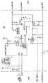
도 12는 센서에 인접한 액체를 처리하기 위한 한 실시 예 회로도 및 관련 방전 타이밍이다. 12 is an embodiment circuit diagram and associated discharge timing for treating a liquid adjacent to a sensor.
안테나에 가해진 전압 또는 전류에서 변화에 대한 시간의 함수로서 안테나의 응답이 측정된다. 상기 안테나의 방전 또는 충전 특성의 적분과 같은 응답이 한 점유자 분류에 맵 된다. 점유자 분류는 점유자 부재, 한 점유자, 물체(가령 자동차 시트), 특정 크기 점유자(가령, 5% 여성 또는 그 이상, 6세 또는 그 이상 또는 다른 그룹 군), 또는 다른 분류를 포함한다. The response of the antenna as a function of time for a change in voltage or current applied to the antenna is measured. Responses such as integration of the discharge or charge characteristics of the antenna are mapped to one occupant class. Occupant classifications include the absence of an occupant, an occupant, an object (such as a car seat), a specific size occupant (eg, 5% female or older, age 6 or older or other group group), or other classification.
상기 점유자 센서 시스템 한 실시 예에서, 샘플 된 전장 범위 내 감지 회로는 상기 센서의 럼프(lump) 커패시턴스 및 저항을 결정하기 위해 한 스텝 전압에 대한 센서의 응답을 사용한다. 한 마이크로-제어기가 안테나를 여자 시킨다. 상기 마이크로 제어기는 또한 아날로그-디지탈 제어기를 포함하며, 안테나에서 측정된 전압을 결정하도록 한다. 전력 소모 및 비용을 최소로 하기 위해, 상기 마이크로-제어기가 충전 및 방전 주기와 관련하여 저 주파수로 동작하며, 낮은 ADC 대역폭으로 동작하도록 한다. 상기 방전 또는 충전 파형은 언더-샘플링을 사용하여 변환기의 통과-대역 내로 고 주파수 내용을 위신호(aliasing) 하므로서 디지탈화된다. In one embodiment of the occupant sensor system, a sampled full-range sensing circuit uses the sensor's response to one step voltage to determine the lump capacitance and resistance of the sensor. A micro-controller excites the antenna. The microcontroller also includes an analog-digital controller and allows to determine the voltage measured at the antenna. In order to minimize power consumption and cost, the micro-controller is operated at a low frequency in terms of charge and discharge cycles and at a low ADC bandwidth. The discharge or charge waveform is digitized by aliasing the high frequency content into the pass-band of the transducer using under-sampling.
또 다른 실시 예에서, 센서 출력에서의 전자장치는 특정 충전 또는 방전이 상기 안테나에서 언제 발생되는가를 출력시킨다. 상기 충전 또는 방전에 도달하기 위한 시간은 상기 충전 또는 방전 응답을 결정하도록 사용된다. 상기 도면 9-12는 이 같은 실시의 실시 예이다. In another embodiment, the electronics at the sensor output output when a particular charge or discharge occurs at the antenna. The time to reach the charge or discharge is used to determine the charge or discharge response. 9-12 show an embodiment of such an embodiment.
도 1-8은 점유자 센서 시스템을 사용한다. 도 9-12는 또 다른 실시 예를 사용한다. 상기 충전 또는 방전 응답을 사용하는 점유자 센서 또는 각기 다른 점유자 센서가 시트 벨트 모니터링 또는 에어 백 작동 제한을 위해 사용된다. 가령, 전장 기초 점유자 센서는 점유자와 물체 사이를 구분하는, 또는 6세 크기와 더욱더 작은 크기를 보다 큰 점유자와 구분하는 시트 내 점유자 존재를 결정한다. 시트 벨트 래치 센서는 시트 벨트가 사용되고 있는 가를 결정한다. 상기 시트 벨트가 사용되고 있지 않다면, 그러나 점유자가 탐지된다면(가령 6세 또는 보다 큰 크기), 한 시트 벨트 경고가 발생 된다. 1-8 use an occupant sensor system. 9-12 use another embodiment. Occupant sensors or different occupant sensors using the charge or discharge response are used for seat belt monitoring or air bag operation limitation. For example, a full-length base occupant sensor determines the presence of occupants in a sheet that distinguishes between an occupant and an object, or that distinguishes between 6-year-old and smaller sizes from larger occupants. The seat belt latch sensor determines whether the seat belt is being used. If the seat belt is not in use, but if the occupant is detected (eg 6 years old or larger), a seat belt warning is issued.
도 1은 점유자 또는 물체 점유자 또는 특징을 탐지하기 위한 점유자 센서 한 실시 예를 도시한다. 상기 점유자 센서는 센서 또는 안테나(12), 전압 스텝 회로(14), 전압 센스 회로(16), 그리고 일련의 저항기(R0)를 포함한다. 추가의 각기 다른 또는 보다 적은 수의 컴포넌트가 제공될 수 있다. 가령 추가의 저항기, 콘덴서, 인덕터가 포함된다. 또 다른 예로서, 전류 스텝 및 감지 회로가 전압에 추가하여 사용된다. 또 다른 예로서 전압 스텝 회로(14)가 충전 또는 방전시 더욱 점진적으로 동작 된다. 멀티 플렉서 또는 추가의 회로(14, 16)를 갖는 두 개 이상의 안테나(12)가 사용될 수 있다. 1 illustrates an embodiment of an occupant sensor for detecting an occupant or object occupant or feature. The occupant sensor comprises a sensor or
상기 안테나(12)는 전극, 루프 전도체, 패턴 전도체, 선형 전도체 또는 다음에 개발될 안테나 이다. 단일 층 또는 멀티플 층 안테나가 사용될 수 있다. 한 실시 예에서, 상기 안테나(12)는 단일 루프 안테나이나, 분리된 전송 및 수신 안테나가 사용될 수 있다. The
상기 안테나(12)는 점유자 공간에 위치하여 진다. 가령, 상기 안테나는 윈도우에 위치하거나, 핸들, 계기판, 시트내, 시트 백에, 시트 베이스에, 차량 바닦 또는 다른 위치에 위치하여 질 수 있다. 한 같은 안테나(12)가 이들 위치 여러개 위치로 연장될 수 있으며, 또는 멀티플 안테나(12)가 각기 다른 위치를 위해 제공될 수 있다. 한 실시 예에서, 한 단일 안테나(12)가 정상적으로 자리에 앉혀진 성인 점유자의 아래측 등(back)에 위치한 한 위치에서 직물 아래와 같은, 상기 점유자 공간에 인접한 한 표면위 시트 베이스 또는 시트 등(seat back)에 위치하여 진다. 가령 상기 안테나(12)는 점유자 공간에 인접한 그리고 상기 자동차 시트 등에 위치한 자동차 시트 베이스 부분에 있다. 상기 시트는 승객, 운전자, 벤치, 버킷 또는 기타 다른 자동차 시트일 수 있다. 영화관 시트와 같은 다른 세팅 시트가 사용될 수 있기도 하다. The
상기 전압 스텝 회로(14)는 상기 안테나(12)에 연결된 전압 또는 전류 소스이다. 상기 전압 스텝 회로(14)는 전원, 디지탈-아날로그 변환기, 또는 다른 상기 안테나(12)로 전압 또는 전류 변화를 가하기 위한 현재 또는 추후 개발 장치와 트랜지스터 또는 스위치와 같은 파형 발생기이다. 상기 전압 스텝 회로(14)는 단일 스텝만을 출력시킨다. 선택적으로, 계속되는 구형파를 적용하는 것과 같은 상기 전압 또는 전류 변화는 반복된다. 한 실시 예에서, 상기 전압 스텝 회로(14)는 0 과 5 볼트 사이 단극 구형파를 발생시키기 위한 트랜지스터이다. 더욱 더 크거나 작은 진폭을 갖는, 및/또는 비-구형 파(가령 사인파)가 사용될 수 있다. The
한 실시 예에서, 상기 펄스 트레인 내 펄스 각각의 전압 부를 증가시키는 것은 상기 펄스 부분을 감소시키는 것과는 다르다. 가령, 상기 증가 전압은 진폭이 점차 전자기 간섭을 줄이도록 한다. 선택적으로, 상기 상승 및 하강 부분은 점진적이며, 상기 상승 부분은 계단식이고, 상기 하강 부분은 점진적이다. In one embodiment, increasing the voltage portion of each pulse in the pulse train is different from reducing the pulse portion. For example, the increasing voltage causes the amplitude to gradually reduce electromagnetic interference. Optionally, the rising and falling portions are gradual, the rising portions are stepped, and the falling portions are gradual.
상기 전압 감지 회로(16)는 아날로그-디지탈 변환기 그리고 전압 및 전류 측정 회로 또는 프로세서이다. 한 실시 예에서, 상기 전압 감지 회로(16)는 상기 전압 스텝 회로(12)를 위해 사용되기도 하는 마이크로 제어기이다. 가령, 상기 전압 감지 회로(16)는 아날로그-디지탈 변환기(ADC) 채널, 내부 오실레이터, 그리고 저 전압 소모장치를 갖는다. 상기 회로는 RC 232 직렬 포트 또는 다른 포트로부터 전력을 공급받는다. 상기 마이크로 제어기의 출력 드라이브 용량은 용량성 부하에 충전 펄스를 제공하기에 충분하다. ADC5의 경우, 상기 사용된 기준은 선형 레귤레이터에 의해 소스된 외부 전압 공급이다. 다른 마이크로-제어기는 동일한 또는 상이 한 특징으로 사용될 수 있다. 선택적으로, 분리된 장치들이 제공된다. 가령, 한 외부 오실레이터가 제공된다. 또 다른 예로서, 한 외부 전압 소스는 ADC 기준이다. The
상기 전압 센스 회로(16)는 한 점유자를 탐지하기위해 동작될 수 있는 점유자 탐지 회로를 포함한다. 프로세서와 같은 전압 센스 회로(16)의 실시 예에서, 상기 프로세서는 감지된 전압 또는 전류의 함수로서 점유자를 특징짓도록 하거나 분류한다. 선택적 실시 예에서, 분리된 프로세서 또는 마이크로-제어기는 시트의 상태(가령 사람에의해 점유된 것인지, 6세 또는 더욱 나이가 든 사람에 의해 점유가 된 것인지)를 특징짓도록 하거나 분류하도록 하기 위해 제공된다. The
전압 감지 회로(16), 전압 스텝 회로(14) 또는 안테나(12)는 회로 보드, 또는 유연한 회로 재료일 수 있으며, 케이블과 함께 연결될 수 있다. 용량이 측정되는 때, 상기 점유자 센서에서 접지 평면으로부터의 용량은 최종 값으로부터 감산된다. 금속 박스 또는 다른 구조가 점유자 센서 회로(14, 16)를 수용하도록 사용될 수 있으며, 플라스틱, 포팅(potting), 어떤 하우징 또는 다른 하우징 재료가 제공될 수 있다. 한 실시 예에서, 인터페이스에 인접한 구리 트레이스 및 필(copper trace and fills)이 제거되거나 감소된다. 상기 점유자 센서는 가드-밴드(guard-band)된다. 표면 마운트, 플립 칩, 또는 다른 마운팅이 상기 컴포넌트를 위해 사용된다. The
도 2는 도 1의 점유자 센서 모델을 도시한다. V0는 상기 전압 스텝 회로(14)로부터 여기 전압이다. R0는 여기 직렬 저항이다. R5는 상기 회로 럼프 직렬 저항에서 센서 및 여기 소스를 마이너스한 것이다. Rp는 상기 센서의 럼프 병렬 저항이 다. Cp는 상기 센서의 병렬 용량이다. Vs는 상기 센서의 측정된 응답이다. 상기 전압 센스 회로(16)는 V8을 측정한다. 상기 센서에 의해 알 수 있는 용량에 대한 일반 식은 다음과 같다. FIG. 2 illustrates the occupant sensor model of FIG. 1. V0 is an excitation voltage from the

상기 용량에 대한 다른 식이 사용될 수 있다. 상기 점유자 센서에 대한 다른 모델이 사용될 수 있다. Other equations for this dose can be used. Other models for the occupant sensor can be used.
상기 안테나(12)의 응답은 안테나(12) 용량의 함수이다. 가령, 상기 점유자가 있을 때 또는 없을 때 안테나(12)는 200 pF 이하의 용량성 부하를 갖는다. 상기 안테나(12)에 인접한 각기 다른 부하를 구분하기 위해, 상기 전압 감지 회로(16)는 1pF로 용량의 변화를 분해한다. 다른 용량 변화 분해가 제공될 수 있기도 하다. 상기 용량 값의 변화는 상기 시스템에 의해 실시되는 지연 루프에 비례한다. 한 상측의 경계가 대략 150pF일 수 있으며, 하측 경계는 대략 3fF일 수 있다. 이들 값은 마이크로 제어기 펌웨어 함수, 지시마다 주기 수 그리고 상기 마이크로제어기의 내부 클록 속도이며, 다른 값이 사용될 수 있다. The response of the
상기 전압 회로(16)는 전압 또는 회로에서의 변화에 대한 안테나(12) 응답 함수로서 분류된다. 상기 전압 센스 회로(16)는 상기 전압 또는 전류 스텝 회로(14) 에 의해 공급된 전압 또는 전류 제 1 변화에 응답하여 시간의 함수로서 안테나(12)에서의 응답을 측정하도록 동작할 수 있다. 가령, 상기 전압 스텝 회 로(14)는 구형파의 전연 또는 후연과 같은 전압에서의 단계를 적용한다. 상기 적용된 전압 또는 전류에서 변화에 응답하여, 상기 안테나(12)에서의 전압 또는 전류가 변화된다. 상기 변경 속도는 상기 용량을 기초로 하여 시간 함수로서 변화한다. The
도 3은 적용된 구형파 3주기를 통해 안테나(12) 전압을 도시한다. 상기 전압에서의 변화는 용량으로 인해 지수적으로 변화한다. 상기 용량은 가해진 전압에서의 더욱 갑작스런 변화에 응답하여 점진적인 전압 변화를 발생시킨다. 상기 변화는 측정된 전압이다. 가령, 전압(충전 전압)이 증가함에 따른 전압에서의 변화가 측정된다. 또다른 예로서, 전압이 감소함에 따른 상기 전압(방전 전압)에서의 변화가 측정된다. 전력 공급에 따른 잡음 효과는 상기 파형 방전 에지를 측정하므로서 측정될 수 있다. 상기 안테나(12)의 충전 및 방전 전압 모두가 측정될 수 있다. 선택적으로, 전류 충전 및 방전이 측정된다. 또 다른 실시 예에서, 예정된 수준에 도달하기 위한 시간이 측정된다. 3 shows the
한 실시 예에서, 상기 변화는 단일 주기 동안 측정된다. 다른 주기로부터의 다른 측정이 평균되고 필터 된다. 또 다른 실시 예에서, 상기 측정 회로는 저 대역폭 측정 장치들에 대하여 설명하기 위해 적용 전압 주기의 반복에서의 변화를 샘플링 한다. 도 3은 안테나(12) 콘덴서 용량에서의 전압 파형 샘플링을 도시한다. 시간이 되면, 샘플 각각이 T+(Δt x n)에서 택해지며, 이와 같은 포인트에서 상기 상응하는 전압이 측정되고 저장된다. 다시 구축되는 때, n 데이터 각각이 충전 또는 방전 시작과 관련하여 Δt 만큼만 시간이 분리된다. 다수 주기로부터의 데이터 포인트는 길이 T인 완전한 파형 하나를 나타낸다. 상기 전압은 줄어든 대역폭 요구와 함께 정량화되며, 더욱 작은 용량 값에 대해 증가된 민감도를 발생시킨다. In one embodiment, the change is measured during a single period. Different measurements from different periods are averaged and filtered. In another embodiment, the measurement circuit samples the change in repetition of the applied voltage period to describe low bandwidth measurement devices. 3 shows voltage waveform sampling at
어떠한 변화 특성도 사용될 수 있다. 가령, 둘 또는 그 이상의 각기 다른 시간에서의 전압 차가 점유자 상태를 나타낸다. 상기 변화, 변화 속도, 상기 주기와 관련한 특정 시간에서의 한 값 또는 상기 안테나 충전 또는 방전 응답 다른 특성이 사용된다. 한 실시 예에서, 상기 측정 회로 또는 전압 감지 회로(16)가 상기 안테나에서의 시간 함수로서 변화들을 통합한다. 상기 재 구축된 충전 또는 방전 파형 영역이 다른 특성보다는 잡음 영향에 덜 민감할 수 있다. 상기 영역이 임의의 유닛 타임 스텝으로 단순화된 사다리꼴 법칙과 같은 스탠다드 숫자 기술을 사용하여 적분하여 계산된다. 이 같은 충전 또는 방전과 충전 모두가 적분된다. 변화 특성에 대한 조화가 사용될 수 있다. 상기 특성은 필터될 수 있다. 타이밍 또는 다른 샘플링이 사용되어 적분을 평가하도록 사용되거나, 적분을 피할 수 있도록 한다. Any change characteristic can be used. For example, voltage differences at two or more different times indicate occupant states. The change, rate of change, one value at a particular time with respect to the period or the other characteristic of the antenna charge or discharge response is used. In one embodiment, the measuring circuit or
전압 감지 회로(16)과 같은 처리기는 상기 안테나(12)의 응답 함수로서 상기 점유자를 특징짓도록 한다. 상기 응답 특징의 각기 다른 값들이 각기 다른 점유자 특징을 나타낸다. 가령, 도 4는 상기 등(back) 가까이 시트 베이스에 위치한 안테나에 대한 방전 적분 값을 도시한다. 상기 데이테 공간은 측정 증분 또는 주기 시간 함수로서 일정 특정 도메인 또는 스케일 내에 있다. 한 절대 시간 스케일이 사용될 수 있다. 상기 값들은 둘 또는 그 이상의 점유자 상태들 사이를 구분하며, 모든 다른 상태로부터 빈 상태를 구분시키도록 한다. 상기 값들은 6세 또는 그 보다 더 어린 점유자를 다른 점유자들로부터 구분할 수 있다. 데이터 클러스터 기술 그룹 데이터는 점유자 부류와 관련 괄찰을 기초로 한 정보를 분리시키도록 한다. 한 가지 타입의 값 또는 그 이상이 포함 될 수 있다. 도 4에서, 상기 접지 상태는 자동차내 접지 물체를 점유자가 접촉하는 것에 해당된다. 상기 접지 되지 않은 상태는 점유자가 자동차 내 접지된 물체를 직접 접촉하고 있지 않음에 해당된다.A processor, such as
유사한 그룹이 타이밍 결정을 위해 사용될 수 있다. 각기 다른 점유자 상태가 충전 또는 방전의 각기 다른 속도와 관련된다. Similar groups can be used for timing determination. Different occupant states are associated with different rates of charging or discharging.
분류 이전 데이터 또는 분류가 필터 될 수 있다.한 실시 예에서, 미국 특허 (공개 번호 제 2003-0204295)에서 공개된 판단 로크 또는 다른 필터링이 사용되며, 상기 공개는 본원 명세서에서 참고된다. 선택적으로, 추가의 필터링 또는 판단 로크는 제공되지 않는다. Pre-classification data or classification may be filtered. In one embodiment, a decision lock or other filtering as disclosed in US Patent Publication No. 2003-0204295 is used, which disclosure is referenced herein. Optionally, no further filtering or decision locks are provided.
도 5는 자동차의 시트(20)에 있는 점유자 센서를 도시한다. 상기 센서 회로(14, 16)는 회로 기판이다. 선택적으로, 플렉시블 회로가 사용된다. 도 6은 상기 시트(20)에 위치한 플렉시블 회로로서, 안테나(12)와 센서 회로(14, 16)를 포함하는 한 실시 예를 도시한다. 상기 안테나(12), 전압 스텝 회로(14) 및 전압 감지 회로(16)는 각기 다른 회로 기판 또는 플렉시블 회로에서 실시 될 수 있다. 5 shows an occupant sensor on a
도 6은 플렉시블 회로 재료를 도시한다. 상기 플렉시블 회로는 플렉시블 필름(52)을 포함한다. 상기 플렉시블 필름(52)은 폴리마이드(캡톤(R)) 필름, PET 폴리에스테르(Mylar(R)) 필름, PEN 폴리틸렌 나프탈라이트 또는 다는 공지의 플렉시블 회로 기판으로 사용하기 위한 플렉시블 회로 재료이다. 상기 플렉시블 회로 재료는 상기 재료에 집적된 능동 또는 수동 회로 소자이거나, 상기 플렉시블 필름(52)은 능동 또는 수동 회로 성분을 갖지 않는다. 6 illustrates a flexible circuit material. The flexible circuit includes a
상기 플렉시블 필름(52)은 상기 재료에 형성된 하나 또는 둘 이상의 안테나(54) 그리고 관련된 신호 트레이스이다. 상기 안테나(54)는 구리, 전도성 전극, 긴장 게이지, 압력 센서, 라디오 주파수 안테나, 압전 필름, 반도체 필름 기초 다이오드 또는 광 탐지기, 이들 조합, 또는 점유자의 존재 또는 특징을 탐지하기 위해 공지된 다른 센서 등이다. 상기 안테나(54)는 용량 또는 전장 또는 용량 기초 감지와 함꼐 사용하기 위한 것이나, 중량 또는 다른 감지기가 사용될 수 있기도 하다. The
상기 안테나(54)는 센서 회로(58)에 의해 사용된다. 상기 센서 회로(58)는 플렉시블 회로 재료(52) 테일(56)상에서 플렉시블 회로로서 형성된다. 상기 신호 트레이스는 안테나 루프(54) 또는 안테나 영역을 상기 센서 회로에 연결시킨다. 상기 트레이스는 모두가 증착되거나 에칭되거나 로울 어닐(rolled annealed) 구리 또는 다른 플렉시블 금속 또는 전도 재와 같은 안테나 루프(54)와 같은 동일 또는 다른 재료이다. The
상기 테일(56)은 수 인치에서 일 야드와 같은 길이를 갖는다. 상기 안테나 루프(54)는 상기 시트(20)내에 있다. 상기 테일(56)은 안테나 루프(54)로부터 한 커넥터 및 가령 에어 백 프로세서 또는 시트 벨트 경고 등과 같은 다른 프로세서 장치로의 연결 위치로 연장된다. 예를들면, 상기 테일(56)은 한 시트 아래로의 연결을 위해 연장된다. The
상기 플렉시블 필름(52)은 고체 재료이나, 상기 안테나(54)를 포함하는 또는 안테나와는 떨어져있는 섹션내 구멍들을 포함할 수 있다. 가령, 하나 또는 둘 이상 의 구멍이 더욱 더 큰 유연성, 공기 흐름, 배수를 허용할 수 있도록 하며, 다른 목적을 위해 제공될 수 있기도 하다. 가령, 상기 구멍들은 더욱 용이하게 상기 플렉시블 필름(52)이 상기 성형된 시트 구조에 일치하도록 한다. The
추가의 컴포넌트가 형성될 수 있으며, 플렉시블 재료(10)에 연결된다. 가령, 온도, 습도 또는 온도 및 습도 센서가 플렉시블 재료(52)에 연결되거나 센서 회로(58) 일부로서 집적된다. 한 실시 예에서, 미국 특허 제 6,816,077 호 에서 공지된 상기 추가 센서 하나가 제공된다. Additional components can be formed and connected to the flexible material 10. For example, temperature, humidity or temperature and humidity sensors are connected to the
선택적 실시 예에서, 상기 센서 회로(58)는 2층 회로 기판과 같은 분리된 회로 기판상에 있다. 두 층의 플렉시블 회로들이 또한 제공될 수 있다. 한 층이 접지 평면으로 작용한다. 상기 접지 평면은 또한 낮은 전달 임피던스 접지 구조를 제공하기도 하며, RF로 분리된다. 선택적으로, 어떠한 접지 평면 또는 차폐도 사용되지 않는다. In an optional embodiment, the
상기 점유자 센서는 에어 백 제어를 위해 사용된다. 가령, 상기 에어 백은 어린 아이들, 몸집이 작은 성인, 또는 무생물 물체에 대해서는 펼쳐지지 않도록 한다. 또 다른 실시 예에서는 상기 점유자 센서가 시트 벨트 모니터링을 위한 센서 시스템이다. 도 5는 시트 벨트 모니터링을 위한 한 실시 예를 도시한다. 상기 시트(20)는 점유자 센서(안테나(12) 및 센서 회로(14, 16), 시트 벨트 래치 센서(24), 그리고 프로세서(26)를 포함한다. 추가의 각기 다른 또는 더욱 적은 수의 컴포넌트가 제공될 수 있다. The occupant sensor is used for airbag control. For example, the airbag does not deploy to young children, petite adults, or inanimate objects. In another embodiment, the occupant sensor is a sensor system for seat belt monitoring. 5 illustrates one embodiment for seat belt monitoring. The
상기 시트 벨트 래치 센서(24)는 전도성 스위치 센서이다. 상기 시트 벨트의 금속 래치가 삽입되거나 래치되면, 전도성 경로가 형성된다. 상기 금속 래치가 삽입되지 않는다면, 개방 회로가 형성된다. 상기 시트 벨트 래치 센서(24)는 상기 시트 벨트 래치 장치를 통해 전압 또는 전류를 기초로 하는 전도 경로 또는 개방 회로를 감지한다. 다른 새로운 시트 벨트 래치 센서(24)가 사용될 수 있기도 하다. The seat
상기 점유자 센서는 안테나(12)를 포함한다. 상기 안테나(12)는 전장, 용량성, 다른 무선 주파수 기초 감지, 적외선, 광학적, 음향적 또는 다른 전달 필드 감지를 위한 것이다. 가령, 상기 음향 센서는 도 1, 2, 3, 또는 4에서 상기 논의된 안테나(12) 그리고 센서 회로(16)를 포함한다. 다른 실시 예에서, 상기 전압 센스 회로(16)는 프로세서, 증폭기, 필터, 응용 특정 집적 회로, 필드 프로그램 가능 게이트 어레이, 디지털 컴포넌트, 이들의 조합 또는 점유자의 존재 또는 특징을 결정하기위한 다른 새로운 장치이다. 가령, 상기 점유자 센서는 광학적, 음향적 또는 적외선 감지를 위한 패턴 인식 또는 다른 처리를 사용한다. 또 다른 실시 예에서, 미국특허제 5,406,627, 5,948,031 , 6,161 ,070, 6,329,913, 6,329,914, 6,816,077, 및 6,696,948호에서 공지된 점유자 탐지 회로 중 하나가 사용되며, 본원에서 참고된다.전장에서 점유자의 영향은 사람 또는 무생물 점유자와 같은 점유자의 존재 또는 특성을 결정하도록 사용된다. 상기 무선 주파수 파의 전달과 관련된 적재 전류 또는 다른 특성은 상기 점유자 정보를 결정하도록 사용된다. 선택적으로 상기 안테나로부터의 전달 그리고 다른 안테나에서의 수신이 사용된다. 다른 전장 또는 용량성 감지 회로가 전장 또는 용량성 값에 대한 점유자 효과 용량, 주파수 변화, 전류 크기, 전압 크기 또는 다른 특성을 결정하기 위한 회로로서 사용 될 수 있다. The occupant sensor includes an
상기 점유자 센서는 점유자와 무생물 물체 사이를 구분할 수 있다. 상기 점유자 센서는 적어도 두 각기 다른 크기 점유자 사이와 같은 다른 부류 사이를 구분할 수 있도록 한다. 점유자의 위치, 키, 자세, 무게, 머리 위치, 다른 점유자 특성이 센서 또는 전극들 위치 및 숫자를 기초로 하여 추가적 및 선택적으로 사용될 수 있다. The occupant sensor can distinguish between an occupant and an inanimate object. The occupant sensor allows to distinguish between different classes, such as between at least two different size occupants. The occupant's position, height, posture, weight, head position, and other occupant characteristics may be additionally and optionally used based on sensor or electrodes position and number.
상기 처리기(26)는 센서 회로(14, 16)의 프로세서이며, 상기 시트 벨트 래치 센서(24), 또는 분리 처리기이다. 가령, 상기 프로세서(26)는 범용 처리기, 디지털 신호 처리기, 응용 특정 집적 회로, 장 프로그램 가능 게이트 어레이, 디지털 회로, 입력 함수로서 경고 신호를 발생시키기 위한 다른 개발 장치이다. 상기 처리기(26)는 상기 점유자 센서에 의해 점유자 탐지에 응답하여, 그리고 상기 시트 벨트 래치 센서에 의한 시트 벨트 래치 부재 탐지에 응답하여 시트 벨트 경고를 발생시킨다. 가령, 상기 점유자 센서는 자동차 리어 시트내 점유자를 탐지하나, 상기 시트 벨트 래치 센서는 상기 리어 시트 위치 내 시트 벨트의 사용을 탐지하지 못한다. 가청 또는 가시의 표시는 운전자에게 경고하며, 상기 탐지된 점유자에게 경고한다. 상기 경고는 자동차 내 시트 위치에 대한 것이다. The
상기 시트 벨트 경고는 각기 다른 크기의 점유자 사이를 구분한다. 가령, 한 시트 벨트 경고는 6세 또는 그 이하 연령 점유자에 대해서는 발생 되지 않는다. 자동차 시트는 시트 벨트가 아니라 래치 시스템을 사용할 수 있으며, 시트 벨트 경고는 자동차 시트 내에 있는 작은 점유자에 대해서는 피하여진다. 상기 구분은 각기 다른 시트 위치에 대해서는 달라질 수 있으며, 운전자 또는 전방 좌석 승객 시트 위치에 대해서는 아무런 크기 구분이 없다. The seat belt warning distinguishes between occupants of different sizes. For example, a seat belt warning does not occur for a six-year-old or younger occupant. The car seat may use a latch system rather than a seat belt, and seat belt warnings are avoided for small occupants in the car seat. The division may vary for different seat positions and there is no size division for the driver or front seat passenger seat positions.
도 7은 점유자를 감지하기 위한 방법을 도시한다. 추가의, 각기 다른 또는 몇 개 않 되는 작용이 사용될 수 있다. 상기 작용은 도시된 순서 또는 각기 다른 순서로 수행된다. 7 shows a method for detecting an occupant. In addition, different or few actions may be used. The actions are performed in the order shown or in different orders.
작용(62)에서, 전압 또는 전류의 변화가 점유자 스페이스에 인접한 안테나에 적용된다. 한 단계 또는 보다 많은 점진적인 변화가 적용된다. 가령 전압 또는 전류의 소스가 안테나로 또는 안테나로부터 연결되거나 연결 차단된다. 또 다른 예로서, 파형 발생기가 전압 또는 전류 진폭 변화를 갖는 파형을 적용시킨다. 상기 변화는 파형 발생기로부터 가해진 전압 또는 전류를 감소시키는 것과 같은 증가 또는 감소이다. 상기 변화는 구형 파를 적용하는 것과 같이 반복될 수 있다. 한 실시 예에서, 전압 또는 전류의 추가 또는 증가가 점차 수행되어 전자기 간섭을 피하도록 한다. 안테나를 점차 충전시킨 후, 상기 전압 또는 전류가 보다 신속하게 제거되며, 상기 안테나를 충전시키는 것보다 더욱 신속하게 상기 안테나를 방전시킨다. 다른 실시 예에서, 상기 방전은 더욱 점진적이며, 충전 및 방전이 신속하거나 스텝 함수이거나, 충전 및 방전 모두가 점진적이다. In
작용(64)에서, 상기 안테나의 응답이 시간의 함수로서 측정된다. 상기 응답은 상기 안테나에 적용된 전압 또는 전류 변화에 대한 것이다. 상기 안테나와 관련된 용량으로 인해, 상기 안테나의 전압 또는 전류가 적용된 파형과 달리 또는 더욱 서서히 변화된다. 상기 안테나 용량은 상기 인접 부하의 함수이다. 상기 안테나는 한 용량성 플레이트로 작용하며 상기 자동차 또는 다른 도체가 접지 플레이트로 작용한다. 시간의 함수로서 상기 안테나에서의 전압 또는 전류를 측정하므로서, 상기 센서에 인접한 점유자의 영향이 측정된다. 가령, 상기 방전 응답 또는 상기 안테나 특성이 측정된다. 시간의 함수로서 상기 특성은 어떤 점유자의 하나 또는 둘 이상의 특성을 나타낸다. 다른 실시 예로서, 상기 응답은 상기 안테나에서의 전압 또는 전류를 사전에 정해진 값과 비교하므로서 측정된다.상기 전류 사전에 정해진 값(가령, 1/3, 2/3 )에 도달하기 위해, 상기 가해진 파형 변화 시작에서와 같은 사전에 정해진 값으로부터의 시간이 측정된다. In
한 실시 예에서, 변화 각각에 대한 응답이 한 변화중에 측정된다. 다른 실시 예에서, 상기 응답은 상기 응답을 결정하기 위해 상기 변화의 멀티플 반복을 통해 샘플된다. In one embodiment, the response to each change is measured during one change. In another embodiment, the response is sampled through multiple iterations of the change to determine the response.
상기 응답은 전압 또는 전류로서 측정된다. 용량, 저항, 임피던스, 또는 다른 특성이 측정될 수 있다. 상기 측정은 점유자 상태를 나타낸다. 선택적으로, 상기 응답은 상기 측정으로부터 계산된다. 가령, 상기 충전 및 방전 응답의 영역이 계산된다. 시간의 함수로서 상기 응답을 집적하여, 잡음의 영향을 줄일 수 있다. 또 다른 실시 예로서 정해진 시작 시간으로부터 하나 또는 둘 이상의 크기에 도달하기 위한 시간이 어떤 점유자 부하로의 안테나 응답을 나타낸다. The response is measured as voltage or current. Capacitance, resistance, impedance, or other characteristics can be measured. The measurement indicates occupant status. Optionally, the response is calculated from the measurement. For example, the area of charge and discharge response is calculated. By integrating the response as a function of time, the effect of noise can be reduced. In another embodiment, the time to reach one or more magnitudes from a given start time represents the antenna response to some occupant load.
작용(66)에서, 어떤 점유자는 상기 응답의 함수로서 분류된다. 임계값, 패턴 매치, 멀티플 측정 분산, 멀티플 측정 타입 분산, 멀티플 각기 다른 계산 분산, 또는 이들의 조합이 둘 또는 그 이상의 점유자 상태를 구분시킨다. 가령, 방전 특성 의 가공되지 않은 또는 평균 영역이 임계값을 기초로 하는 점유자의 적어도 두 크기 범위 사이를 구분시킨다. In
한 실시 예에서, 한 공통 프로세서가 모듈러 감지 회로와 연결된다. 상기 감지 회로는 적분, 전압 값, 전류 값, 타이밍, 또는 상기 공통 프로세서에 대한 다른 측정된 특성과 같은 측정 정보를 전달시킨다. 상기 공통된 프로세서는 한 점유자 공간에 대한 점유자 상태를 결정한다. 상기 공통 프로세서는 상기 감지 회로 및/또는 사이드에 있는 감지 회로 및 안테나를 갖는 시트 아래에 있는, 또는 시트 표면에 있는, 감지 회로 또는 안테나로부터 떨어져 있다. 버스 또는 다른 통신 경로는 구성가능한 수의 사용되어질 모듈러 감지 회로 및 관련된 안테나를 허용한다. In one embodiment, one common processor is coupled with modular sensing circuitry. The sensing circuit conveys measurement information such as integration, voltage value, current value, timing, or other measured characteristic for the common processor. The common processor determines the occupant state for one occupant space. The common processor is remote from the sensing circuitry or antenna, under the sheet having the sensing circuitry and / or sensing circuitry and / or side, or on the surface of the sheet. Buses or other communication paths allow for a configurable number of modular sensing circuits and associated antennas to be used.
도 8은 시트 벨트 모니터링을 도시한다. 도 7의 방법을 사용하여, 시트 벨트 경고는 분류의 함수로서 발생된다. 다른 점유자 탐지 방법이 사용될 수 있다. 추가적으로, 도 8에서 도시된 것과 다른 더욱 적은 수의 작용이 사용될 수 있다. 상기 작용들은 도시된 또는 다른 순서로 수행된다. 가령, 작용(74)은 작용(72)과 동시에 또는 그 전에 수행된다. 8 shows seat belt monitoring. Using the method of FIG. 7, seat belt warnings are generated as a function of classification. Other occupant detection methods may be used. In addition, fewer actions other than those shown in FIG. 8 may be used. The actions are performed in the order shown or in other order. For example,
작용(72)에서, 시트 벨트는 래치되고 탐지된다. 시트 벨트 센서는 시트 벨트가 래치, 확장 또는 조여지는 가를 전도도 또는 다른 감지를 탐지한다. 작용(74)에서, 점유자가 존재하는가는 전장으로 탐지된다. 용량, 전류 담김, 광학적 또는 다른 전장 기초 감지가 사용될 수 있다. 선택적으로, 음향의 또는 하중 센서가 사용된다. 상기 점유자 탐지가 무생물 물체와 사람 사이를 구분하며, 적어도 두 크기 범위의 점유자 사이를 구분한다. 작용(76)에서, 시트 벨트 경고가 시트 벨트가 래 치되지 않고 점유자가 존재하면 발생 된다. 가령, 가청 경보 또는 가시 표시가 한 크기 범위의 점유자에 대하여 발생되며 다른 크기 범위에 대해서는 발생되지 않는다. 다른 실시 예에서, 충전 또는 방전의 타이밍, 모듈러 센서, 또는 이들의 조합이 사용된다. 도 9-11이 실시 예를 도시한다. In
도 9는 점유자 탐지에 대한 센서 시스템 또다른 실시예를 도시한다. 상기 센서에서의 전자 장치는 언제 특정 충전 또는 방전이 상기 안테나에서 발생되는 가에 대한 표시를 출력시킨다. 충전 또는 방전에 도달하기 위한 시간이 사용되어, 상기 충전 또는 방전 응답을 결정하도록 한다. 상기 출력은 상기 센서 회로로부터 떨어진 프로세서로의 통신 경로 위에 있다. 충전 또는 방전의 모듈러 및 타이밍은 도 9의 실시 예에서 도시된 바와 같이 함께 사용될 수 있다. 선택적으로, 타이밍 또는 모듈러 센서 회로는 다른 회로 없이 사용될 수 있다. 9 shows another embodiment of a sensor system for occupant detection. The electronic device at the sensor outputs an indication of when a particular charge or discharge is occurring at the antenna. Time to reach charge or discharge is used to determine the charge or discharge response. The output is on the communication path from the sensor circuit to the processor. Modularity and timing of charge or discharge can be used together as shown in the embodiment of FIG. 9. Optionally, timing or modular sensor circuitry can be used without other circuitry.
상기 점유자 탐지 센서 시스템은 안테나(93) 및 센서 전자장치(100), 프로세서(98), 버스(94) 그리고 파워 연결(96)을 포함한다. 추가의, 각기 다른 또는 몇 안되는 컴포넌트가 상기 버스(94)의 일부로서 파워 연결(96)을 제공하는 것과 같이 제공될 수 있다. The occupant detection sensor system includes an
상기 센서(92)는 얇은 유전체에 의해 분리된 두 개의 구리층을 갖는 안테나(93)를 포함한다. 상기 안테나(93)의 하측 층은 시트 히터 구조 또는 시트의 다른 금속 구조와 상측 층 사이에 있다. 이 같은 하측 층은 접지 또는 전달 신호와 연결된 것과 같은 차단 층으로 사용된다. 분리된 차단 신호가 사용될 수 있다. 도 1에 대하여 상기 설명된 바와 같은 다른 안테나 구조가 사용될 수 있다. The
세 개의 센서(92)가 도시되며, 추가의 또는 더욱 작은 수의 센서가 사용될 수 있다. 상기 센서(92)는 모듈러이며, 각기 다른 수 센서(92)들 연결을 허용한다. 상기 프로세서(98)는 공통 프로세서이며, 각기 다른 수 센서(92)와 함께 동작하기 위한 지시를 포함하거나, 또는 각기 다른 지시 세트가 사용되어질 센서(92) 수를 기초로 하여 적제된다. 각기 다른 점유자 탐지 시스템은 점유자의 각기 다른 특성 또는 타입을 결정한다. 더욱 더 많은 수 센서(92)가 각기 다른 또는 멀티플 특성을 결정할 수 있도록 한다. 더욱 적은 수의 센서(92)는 비용을 줄이도록 사용될 수 있다. 상기 센서(92)의 모듈러 특성으로 인해 각기 다른 상황에 사용될 수 있다. 각기 다른 실시 예가 아닌, 상기 모듈러 특성이 컴포넌트 부분의 생산을 허용하도록 하며, 어떠한 수의 안테나(93)로도 바람직한 시스템의 어셈블리를 허용하도록 한다. Three
상기 센서(92)는 센서 전자 장치(100)을 포함한다. 상기 센서 전자 장치(100)는 상기 프로세서(98)와 통신하기 위한 아날로그, 디지탈 또는 다른 회로를 포함한다. 통신 경로는 상기 센서 전자장치(100)를 상기 프로세서(98)에 연결시킨다. 도 9에서 도시된 실시 예에서, 상기 센서 전자장치(100)는 멀티플 드롭 직렬 인터페이스(가령, I2C 버스)에서와 같은 버스 통신을 위한 회로를 포함한다. 선택적 실시 예에서, 선서(92)들 및 프로세서(98)사이 직접 또는 와이어 연결이 제공된다. 가령, 상기 프로세서(98)은 하나 또는 둘 이상의 센서(92)와의 광학적 연결을 위한 다수의 입력을 포함한다. The
상기 버스(94)는 I2C 버스와 같은 멀티플 드롭 직렬 인터페이스이다. 다만, 다른 버스가 사용될 수 있기도 하다. 상기 파워 연결(96)은 상기 버스(94) 일부로서 포함될 수도 있고, 이로부터 분리될 수 있기도 하다. 상기 버스(94)는 제어 신호를 제공하여, 상기 센서(92)를 충전하고 방전하도록 하며, 측정을 위한 충전 또는 방전을 선택할 수 있도록 한다. 추가의, 각기 다른 또는 몇 안되는 제어 신호가 제공될 수 있다. 상기 버스(94)는 상기 센서(92)로부터 트리거 또는 타이밍 신호들을 수신한다. 가령, 상기 센서(92)는 도 1-8과 관련하여 상기 설명된 개별 안테나에 대한 측정을 출력시킨다. 또 다른 실시 예로서, 센서(92)는 위상, 용량, 전류, 전장, 또는 다른 측정된 값을 출력시킨다. The
상기 파워 연결(96)은 배터리와 연결된다. 상기 연결은 자동차등에서의 점화에 응답하여 파워를 제공하는 것과 같이 스위치 가능하다. The
도 9는 방전 또는 충전을 측정하기 위한 센서 전자 장치(100) 한 실시 예를 도시한다. 상기 센서 전자 장치(100)는 상기 안테나(93)에 응답하여 디지탈 정보와 같은 출력 데이터로의 전자 장치를 포함한다. 아날로그 데이터가 출력될 수 있다. 프로세서, 응용 특정 집적 회로, 아날로그-디지털 변환기, 아날로그 회로, 디지털 회로, 또는 이들의 조합과 같은 회로가 사용될 수 있다. 9 illustrates one embodiment of a sensor
한 실시 예에서, 상기 센서 전자 장치(100)는 상기 상측 및 하측 층(센서 및 차페 전자 장치), 증폭기(106), 저항기 네트워크(R1, R2, R3), 감지 저항기 R 센스, 전압 입력 Vcc, 비교기(104), 및 출력(타이머/카운터 트리거)를 위한 연결 또 는 안테나 커넥터를 포함한다.추가의 각기 다른 또는 몇 안되는 컴포넌트들이 제공될 수 있다. In one embodiment, the
도 10은 마이크로 제어기 또는 다른 프로세서로서 부분적으로 실시 되는 상기 감지기 전자장치(100) 회로 한 실시 예를 도시한다. 상기 비교기(104) 그리고 상기 버스 인터페이스 전자장치는 상기 마이크로 제어기 내에 제공된다. 상기 측정 포이트의 제어는 또는 상기 마이크로 제어기 내에 제공된다. 다른 처리의 분산이 사용될 수 있다. FIG. 10 illustrates one embodiment of the
각 센서는 접지에 연결된다. 한 실시 예에서, 상기 접지는 자동차 차체 접지이다. 한 전압 레귤레이터가 상기 입력 파워 또는 전압의 동요(surge)를 피하게 한다. 한 실시 예에서, 상기 레귤레이터는 선형 레귤레이터이다. 다만, 다른 레귤레이터가 사용될 수 있기도 하다. 상기 전압은 신호로서 제공된다.Each sensor is connected to ground. In one embodiment, the ground is the vehicle body ground. One voltage regulator avoids the surge of the input power or voltage. In one embodiment, the regulator is a linear regulator. However, other regulators may be used. The voltage is provided as a signal.
상기 증폭기(106)는 높은 회전율(slew rate), 낮은 DC 오프셋 전압, 낮은 입력 바이어스 전류, 낮은 잡음 수치, 단일 공급 동작 및 레일-레일 출력 동작 전압 레인지를 갖는다. 다른 특성을 갖는 증포기가 사용될 수 있기도 하다. 도면에서는 분리되어 도시되어 있으나, 상기 증폭기(106)는 다른 실시 예 내에 마이크로 제어기 내로 집적될 수 있기도 하다. The
저역 통과 필터 LPF는 마이크로 제어기 및 상기 아날로그 선택기 사이에서 연결된다. The low pass filter LPF is connected between the microcontroller and the analog selector.
상기 저항기 (R1, R2, 및 R3)는 10K 오옴과 같은 같은 값을 갖는다. 다른 더욱 높은 또는 낮은 저항이 사용될 수 있기도 하다. 상기 저항은 매치된다. 선택적 으로 상기 저항기는 각기 다른 저항을 갖는다. 추가의 또는 다른 저항기 네트워크가 사용될 수 있기도 한다. 상기 센서 저항기는 상기 비교기(104) 포지티브 입력에서의 잡음을 최소로 하기에는 작다. 가령, R센스는 10K 오옴이며, 다만 더욱 크거나 작은 값이 사용될 수 있기도 한다. The resistors R1, R2, and R3 have a value equal to 10K ohms. Other higher or lower resistances may be used. The resistance is matched. Optionally, the resistors have different resistances. Additional or other resistor networks may be used. The sensor resistor is small to minimize noise at the
다시 9도를 참고로 하여, 상기 센서 전자장치(100)는 상기 프로세서(98)과 관련하여 동작된다. 상기 프로세서(98)는 상기 입력(102)의 연결을 선택한다. 선택적으로, 상기 센서 전자 장치(100)는 상기 연결을 선택한다. 제로, 접지, 또는 낮은 전압 연결이 0으로 지정된다. 상기 0 연결은 결국 병렬의 R2 및 R1을 만들도록 한다. 이 같은 장치는 상기 비교기(104) 네가티브 또는 포지티브 입력 기준 전압으로서 전체 충전의 2/3 진폭을 만들도록 한다. 고 전압 또는 최대 전압(가령, Vcc) 연결은 1로 지정된다. 상기 1 연결은 병렬인 R1 및 R3를 만들도록 한다. 이 같은 장치는 상기 비교기(104) 입력으로 기준 전압으로서 전체 충전의 1/3 진폭 또는 전압을 만들도록 한다. 높은 임피던스 연결은 X 로 지정된다. 상기 X 연결은 R1을 통해 결국 아무런 전류 통과를 일으키지 않는다. R2 및 R3는 같은 값이기 때문에, 1/2 진폭 또는 전압이 상기 비교기(104)로 입력된다. 상기 입력(102) 및 저항기 네트워크를 사용하여, 상기 센서 전자 장치(100)는 충전 또는 방전을 위한 세 개의 각기 다른 전압 크기를 측정한다. 다른 네트워크 또는 전자 장치가 사용되어, 상기 비교기를 위한 기준 전압을 제공하는, 프로세서(98)와 같은 동일한 또는 각기 다른 수의 전압 크기를 측정하기 위해 다른 네트워크 또는 전자 장치가 사용될 수 있다. 전류와 같은 다른 특징이 측정될 수 있기도 하다. Referring back to FIG. 9, the
상기 각기 다른 크기가 상기 저항기 값들에 의해 사전에 결정된다. 상기 네트워크로 또는 네트워크로부터 스위치될 수 있는 추가 네트워크 컴포넌트를 포함하는 것과 같은 프로그램 가능 크기들이 사용될 수 있기도 하다. 가능한 크기들 전부 또는 단지 일부가 정해진 실시에서 사전에 정해진 컴포넌트로서 사용될 수 있다. The different sizes are predetermined by the resistor values. Programmable sizes may also be used, such as including additional network components that can be switched into or out of the network. All or only some of the possible sizes may be used as a predetermined component in a given implementation.
상기 측정 전압 또는 진폭을 선택한 후에, 상기 프로세서(98) 또는 센서 전자 장치(100)가 계수기를 시작시킨다. 상기 계수기는 상기 안테나(93)에 적용된 신호의 충전 시간에서 시작되나, 다른 시간(가령 첫 번째 사전 정해진 크기가 도달되는 때) 시작될 수 있기도 한다. 상기 스텝 입력은 증폭기(106)로 제공되거나, 상기 충전은 상기 프로세서(98) 또는 상기 센서 전자 장치(100)에 의해 상기 증폭기(106)로부터 전압을 제거하여 방전된다. 상기 안테나(93)가 방전 또는 충전에 도달하는 때, 상기 비교기가 한 트리거 신호를 출력시킨다. 응답하여, 상기 프로세서(98) 또는 센서 전자 장치(100)는 상기 포인트에 도달하는 데 걸리는 계수기 시간을 측정한다. 실 시간, 시간 차, 주기 수, 또는 다른 일시적 표시가 사용될 수 있다. 한 실시 예에서, 트리거 신호가 발생되며 상기 공통 프로세서(98)가 상기 시간 정보를 결정한다. After selecting the measured voltage or amplitude, the
상기 처리는 각기 다른 측정 포인트(가령, 1/3, 1/2, 및 2/3), 또는 상기 안테나(93)의 충전 또는 방전에 대하여 반복된다. 하나, 둘 또는 세 번의 측정과 같은 적은 회수 측정으로도 센서(92) 각각에 대하여 사용될 수 있다. 한 실시 예에서는 충전에 대하여 세 번, 방전에 대하여 세 번, 여섯 번의 측정이 사용된다. 어떠한 회수의 측정이 사용될 수 있기도 하다. 상기 센서(92)는 순서적으로 동작되나, 동시에 동작될 수 있기도 하다. 각기 다른 타이밍 측정이 상기 프로세서(98)에 의해 사용되어 상기 점유자 상태를 결정하도록 한다. 상기 타이밍은 충전 또는 방전의 영역 또는 적분을 나타내거나, 이에 상응하거나, 또는 대체에 해당한다. The process is repeated for different measuring points (
공지의 용량이 한 기준으로 사용되어 상기 측정의 정확도를 개선하도록 할 수있다. 상기 아날로그 선택기는 스위치, 트랜지스터, 릴레이, 또는 상기 각기 다른 연결사이를 선택하기 위한 다른 장치이다. 상기 센서로의 연결 대신, 저항기 R센스가ㅣ 선택적으로 하나 또는 둘 이상 기준 콘텐서(가령, C1 및 C2)에 연결된다. 동작 또는 다른 시간 시작에서, 기준 용량(가령, C1 또는 C2)이 측정된다. 가령, 두 공지된 용량 C1 및 C2 모두가 측정된다. 그 결과가 상기 센서로부터 측정된 값을 보상하도록 사용된다. 룩-엎 테이블, 함수, 또는 다른 관계가 사용되어, 측정된 값을 조정하고, 계산된 결과를 조정하거나, 상기 기준 측정을 기초로 각기 다른 최로 성분을 선택하도록 한다. 상기 기준 측정을 사용하므로서, 상기 회로 변화 또는 온도 영향을 보상할 수 있도록 한다. Known doses can be used as a criterion to improve the accuracy of the measurement. The analog selector is a switch, transistor, relay, or other device for selecting between the different connections. Instead of connecting to the sensor, a resistor R sense is optionally connected to one or more reference capacitors (eg, C1 and C2). At the start of an action or other time, a reference dose (eg, C1 or C2) is measured. For example, both known doses C1 and C2 are measured. The result is used to compensate for the value measured from the sensor. Look-up tables, functions, or other relationships may be used to adjust the measured values, adjust the calculated results, or select different maximum components based on the reference measurements. By using the reference measurement, it is possible to compensate for the circuit change or temperature influence.
상기 센서 전자장치(100)는 전류 인젝션으로 인한 잡음을 제거하거나, 줄일 수 있도록 한다. 상기 센서 전자장치(100)는 직렬, 병렬, 또는 다른 포맷으로 상기 프로세서(98)에 연결될 수 있다. The
상기 프로세서(98)는 범용 프로세서, 집적 회로, 필드 프로그램 가능 게이트 어레이, 아날로그 회로, 디지털 회로, 이들의 조합 또는 다른 개선된 장치로서 센서 측정으로부터 점유자 상태를 결정하도록 한다. 점유자 분류를 결정하기 위한 클러스터와 같은 어떠한 점유자 상태 결정이 사용될 수 있기도 하다. The
한 실시 예에서, 상기 프로세서(98)는 상기 버스(94)를 위한 마스터 제어기이다. 상기 프로세서(98)는 에어 백 제어기 또는 시트 벨트 경고 시스템과 같은 결정된 점유자 분류 장치와 통신 한다. In one embodiment, the
도 11은 상기 프로세서(98) 한 실시 예를 도시한다. 상기 프로세서(98)는 직렬 버스 EEPROM, 분류 장치를 위한 마이크로 제어기 그리고 자동차 시스템과의 통신을 위한 CAN 송수신기이다. 11 illustrates one embodiment of the
상기 프로세서(98)는 동일한 회로 기판상에 있으며, 한 동일한 하우징 내에 있으며, 상기 센서 전자장치(100)에 인접하여 있다. 가령, 테일 또는 와이어가 상기 안테나(93)를 상기 전자장치(100)에 연결시키는 하나 또는 둘 이상의 전자 장치를 수용 할 수 있는 한 하우징 내 하나 또는 둘 이상의 센서 전자 장치(100) 각각을 연결시킨다. 한 백 플레인(backplane) 또는 다른 커넥터가 상기 하우징 내 프로세서(98)를 전자 장치(100)를 연결시킨다. 또 다른 실시 예에서, 상기 프로세서(98)는 센서 전자 장치(100)로부터 떨어져 있다. 가령, 상기 센서 전자 장치(100)는 플렉시블 회로이며, 상기 점유자 공간에 인접한 안테나(93)에 인접하여 위치한다. 상기 프로세서(98)는 시트 아래와 같이 자동차 내 다른 곳에 위치한다. 상기 프로세서(98)는 분리된 하우징 내에 있다. The
한 실시 예에서, 상기 프로세서(98)는 단일 점유자 공간에 대하여 동작된다. 각 점유자 공간(가령, 시트 영역)에 대하여, 분리된 프로세서(98)가 제공된다. 다른 실시 예에서, 한 프로세서(98)가 둘 또는 그 이상의 점유자 공간에 대하여 점유자 상태를 결정한다. In one embodiment, the
상기 시스템은 특정 웨트 탐지 없이 동작할 수 있다. 다른 실시 예에서, 각기 다른 센서 연결 또는 조합으로 측정하여, 액체의 영향을 줄이거나 액체의 영향을 측정하여 보상할 수 있도록 사용될 수 있다. 선택적 실시 예에서, 분리된 웨트 센서가 사용된다. 상기 센서에 인접한 액체는 상기 센서 시스템의 차폐, 절연, 방수, 위치 또는 다른 특성에 따라 측정에 영향을 미칠 수 있다. 상기 센서와 부하(load) 사이 액체는 용량과 같은 전장 측정을 변경하기 쉬울 수 있다. 습윤을 측정함으로써, 상기 영향이 측정된 값, 함수, 임계 값 또는 다른 정보를 조정하여 보상(counteract)될 수 있다.The system can operate without specific wet detection. In other embodiments, it can be used to measure by different sensor connections or combinations, to reduce the effects of liquids or to measure and compensate for the effects of liquids. In alternative embodiments, separate wet sensors are used. The liquid adjacent to the sensor may affect the measurement depending on the shielding, insulation, waterproofing, location or other characteristics of the sensor system. The liquid between the sensor and the load can be susceptible to changing electrical field measurements such as capacity. By measuring wetting, the influence can be counteracted by adjusting the measured value, function, threshold or other information.
한 실시 예에서, 상기 측정된 신호의 실수 및 허수 성분이 분리된다. 상기 실수 성분 만에서의 변화를 측정함으로써, 상기 센서에 인접한 어떠한 액체도 탐지 되거나, 액체의 영향이 줄어들 수 있다. 상기 용량성 컴포넌트는 더욱 액체에 응답할 가능성이 높다. 상기 저항 또는 용량성 성분 어느 하나를 사용하여, 충분한 양의 액체 또는 영향이 탐지 될 수 있다. 탐지된 액체로 인해, 오유 신호 또는 불 이행 출력이 측정된 점유 여부에 의존하지 않고 발생될 수 있다. 추가적으로 또는 선택적으로, 측정된 값들이 저항 값을 기초로 하여 용량성 값으로 보상되는 바와 같이, 측정된 액체에 대하여 보상된다. In one embodiment, the real and imaginary components of the measured signal are separated. By measuring the change in only the real component, any liquid adjacent to the sensor can be detected or the influence of the liquid can be reduced. The capacitive component is more likely to respond to the liquid. Using either the resistive or capacitive component, a sufficient amount of liquid or effect can be detected. Due to the liquid detected, an oil signal or a failure output can be generated without depending on the occupancy measured. Additionally or alternatively, the measured values are compensated for the measured liquid as compensated for the capacitive value based on the resistance value.
실수 성분과 허수 성분을 분리시키기 위해, 두 방전 경로가 제공될 수 있다. 도 12는 두 방전 경로를 갖는 한 실시 예를 도시한다. 상기 두 방전 경로는 선택 가능한 방전 저항 RdI 및 Rd2를 포함한다. 저항성 및 용량성 컴포넌트는 각 경로의 저항 값 및 상응하는 방전 시간을 사용하여 분리하여 계산된다. 각 경로를 사용하 여 상기 방전 시간(t dchgl, t dchg2)을 측정하는 것은 상기 프로세서가 C 와 R 사이를 구분할 수 있도록 한다. 가령: In order to separate the real and imaginary components, two discharge paths may be provided. 12 shows one embodiment with two discharge paths. The two discharge paths include selectable discharge resistors RdI and Rd2. Resistive and capacitive components are calculated separately using the resistance value of each path and the corresponding discharge time. Measuring the discharge time (t dchgl, t dchg2) using each path allows the processor to distinguish between C and R. chamberlain:

여기서 Eisf 5 볼트, RdI는 46 K 오옴, Rd2는 270 K 오옴, 그리고 Vt 는 바람직한 임계값으로 세트된다. 다른 값들이 사용될 수 있기도 하다. Where
본 발명이 여러 실시 예를 참고로 하여 상기 설명되었으나, 본 발명 범위를 벗어나지 않는 한도에서 많은 변경이 가능한 것이다. Although the present invention has been described above with reference to various embodiments, many changes are possible without departing from the scope of the present invention.
Claims (29)
Applications Claiming Priority (5)
| Application Number | Priority Date | Filing Date | Title |
|---|---|---|---|
| US77551506P | 2006-02-21 | 2006-02-21 | |
| US60/775,515 | 2006-02-21 | ||
| US11/676,472 US7791476B2 (en) | 2006-02-21 | 2007-02-19 | Occupant sensor and method for seat belt or other monitoring |
| US11/676,472 | 2007-02-19 | ||
| PCT/US2007/004535 WO2007098216A2 (en) | 2006-02-21 | 2007-02-20 | Occupant sensor and method for seat belt or other monitoring |
Publications (2)
| Publication Number | Publication Date |
|---|---|
| KR20080098375A true KR20080098375A (en) | 2008-11-07 |
| KR101050005B1 KR101050005B1 (en) | 2011-07-19 |
Family
ID=38427593
Family Applications (1)
| Application Number | Title | Priority Date | Filing Date |
|---|---|---|---|
| KR1020087020363A KR101050005B1 (en) | 2006-02-21 | 2007-02-20 | Passenger detection sensor and method for monitoring seat belts or others |
Country Status (9)
| Country | Link |
|---|---|
| US (1) | US7791476B2 (en) |
| EP (1) | EP1986884A4 (en) |
| JP (3) | JP4740346B2 (en) |
| KR (1) | KR101050005B1 (en) |
| CN (1) | CN101389507B (en) |
| BR (1) | BRPI0708171A2 (en) |
| CA (1) | CA2642222C (en) |
| MX (1) | MX2008010740A (en) |
| WO (1) | WO2007098216A2 (en) |
Cited By (1)
| Publication number | Priority date | Publication date | Assignee | Title |
|---|---|---|---|---|
| CN107650739A (en) * | 2016-07-26 | 2018-02-02 | 现代自动车株式会社 | The object discriminating device of seat |
Families Citing this family (47)
| Publication number | Priority date | Publication date | Assignee | Title |
|---|---|---|---|---|
| US7163263B1 (en) * | 2002-07-25 | 2007-01-16 | Herman Miller, Inc. | Office components, seating structures, methods of using seating structures, and systems of seating structures |
| US7791476B2 (en) | 2006-02-21 | 2010-09-07 | Elesys North America, Inc. | Occupant sensor and method for seat belt or other monitoring |
| EP1837248A1 (en) * | 2006-03-20 | 2007-09-26 | IEE INTERNATIONAL ELECTRONICS & ENGINEERING S.A. | Occupant classification system |
| JP4609731B2 (en) * | 2006-10-31 | 2011-01-12 | 株式会社デンソー | Capacitive occupant detection sensor |
| JP4305526B2 (en) * | 2007-02-21 | 2009-07-29 | 株式会社デンソー | Capacitive occupant detection system and occupant protection system |
| US20080277910A1 (en) * | 2007-05-10 | 2008-11-13 | Tk Holdings Inc. | Vehicle seat including sensor |
| DE102007025518A1 (en) * | 2007-05-31 | 2008-12-04 | BROSE SCHLIEßSYSTEME GMBH & CO. KG | Motor vehicle door assembly |
| US8577711B2 (en) * | 2008-01-25 | 2013-11-05 | Herman Miller, Inc. | Occupancy analysis |
| ATE523387T1 (en) | 2008-05-29 | 2011-09-15 | Delphi Tech Inc | SEAT BELT WARNING SYSTEM |
| US8036795B2 (en) * | 2008-10-08 | 2011-10-11 | Honda Motor Company, Ltd. | Image based occupant classification systems for determining occupant classification and seat belt status and vehicles having same |
| US8116528B2 (en) * | 2008-10-08 | 2012-02-14 | Honda Motor Company, Ltd. | Illumination source for an image based occupant classification system and vehicle using same |
| US8195356B2 (en) | 2008-10-08 | 2012-06-05 | Honda Motor Co., Ltd. | Methods for testing an image based occupant classification system |
| JP5146257B2 (en) * | 2008-10-27 | 2013-02-20 | トヨタ紡織株式会社 | Seat seating detection system |
| JP4817026B2 (en) * | 2009-06-16 | 2011-11-16 | 株式会社デンソー | Electrostatic occupant detection device |
| JP4752956B2 (en) * | 2009-06-16 | 2011-08-17 | 株式会社デンソー | Electrostatic occupant detection device |
| JP4817027B2 (en) * | 2009-06-16 | 2011-11-16 | 株式会社デンソー | Electrostatic occupant detection device |
| JP5332997B2 (en) * | 2009-07-17 | 2013-11-06 | アイシン精機株式会社 | Seat belt warning device |
| JP4892597B2 (en) * | 2009-09-28 | 2012-03-07 | 株式会社ホンダエレシス | Occupant detection system |
| DE102010002504B4 (en) * | 2010-03-02 | 2017-02-09 | TAKATA Aktiengesellschaft | Method and device for checking an electronic device |
| KR101232432B1 (en) * | 2010-11-12 | 2013-02-12 | 현대모비스 주식회사 | Occupant classifying device for an automobile |
| JP2012107895A (en) * | 2010-11-15 | 2012-06-07 | Honda Elesys Co Ltd | Occupant detection system |
| LU91838B1 (en) * | 2011-07-08 | 2013-01-09 | Iee Sarl | Seat heater and capacitive occupancy sensor combination |
| LU91843B1 (en) * | 2011-07-20 | 2013-01-21 | Iee Sarl | Plural-frequency capacitive occupancy sensing system |
| LU91923B1 (en) * | 2011-12-21 | 2013-06-24 | Iee Sarl | Occupancy sensor for occupiable item e.g. seat or bed |
| EP2712021B1 (en) * | 2012-09-21 | 2018-04-04 | Siemens Aktiengesellschaft | Antenna for a read/write device for RFID assemblies and read/write device for operation with an external antenna |
| EP2910413A1 (en) * | 2014-02-25 | 2015-08-26 | Sensirion AG | Seat assembly with temperature or humidity sensor |
| LU92604B1 (en) * | 2014-11-24 | 2016-05-25 | Iee Sarl | Vehicle seat |
| MX2017008537A (en) * | 2014-12-27 | 2018-02-21 | Guardian Optical Tech Ltd | System and method for detecting surface vibrations. |
| US10093262B2 (en) * | 2015-03-31 | 2018-10-09 | Ford Global Technologies, Llc | Seatbelt payout measuring device and system |
| US11040682B1 (en) | 2016-03-21 | 2021-06-22 | Paradigm Research and Engineering, LLC | Blast detection and safety deployment system and method for using the same |
| JP6759689B2 (en) | 2016-05-10 | 2020-09-23 | ヤマハ株式会社 | Distortion sensor unit |
| US10442328B2 (en) * | 2016-06-21 | 2019-10-15 | Kongsberg Automotive Ab | Assembly, system, and circuit with combined heating and occupancy detecting for a vehicle seat |
| US10457163B2 (en) * | 2016-07-20 | 2019-10-29 | Joyson Safety Systems Acquisition Llc | Occupant detection and classification system |
| CN106525318B (en) * | 2016-12-16 | 2022-07-01 | 山东金洲科瑞节能科技有限公司 | Bus type pressure measuring device |
| JP6642474B2 (en) * | 2017-02-13 | 2020-02-05 | オムロン株式会社 | State determination device, learning device, state determination method, and program |
| CN106772623A (en) * | 2017-03-17 | 2017-05-31 | 深圳市电应普科技有限公司 | A kind of condenser type seat sensor and method of work |
| US10317448B2 (en) * | 2017-05-22 | 2019-06-11 | Swift Engineering, Inc. | Human sensing using electric fields, and associated systems and methods |
| KR20200037424A (en) * | 2017-08-29 | 2020-04-08 | 텍추얼 랩스 컴퍼니 | Vehicle components including sensors |
| US11070904B2 (en) | 2018-09-21 | 2021-07-20 | Apple Inc. | Force-activated earphone |
| US11463797B2 (en) | 2018-09-21 | 2022-10-04 | Apple Inc. | Force-activated earphone |
| CN109910707A (en) * | 2019-03-20 | 2019-06-21 | 天津比亚迪汽车有限公司 | A kind of energy conservation city bus seat |
| CN113874259B (en) | 2019-04-04 | 2023-11-03 | 乔伊森安全系统收购有限责任公司 | Detection and monitoring of active optical retroreflectors |
| FR3098769B1 (en) | 2019-07-15 | 2022-10-07 | Faurecia Sieges Dautomobile | VEHICLE SEAT WITH COMPENSATION SYSTEM |
| EP3865340A1 (en) * | 2020-02-17 | 2021-08-18 | AMF-Bruns GmbH & Co. KG | Passenger safety system for securing persons in vehicles with reversibly mounted vehicle seats |
| US20230246601A1 (en) * | 2022-01-31 | 2023-08-03 | Qorvo Us, Inc. | Protection circuit for acoustic filter and power amplifier stage |
| DE102022105486A1 (en) | 2022-03-09 | 2023-09-14 | Zf Automotive Germany Gmbh | HAND RECOGNITION DEVICE FOR A STEERING WHEEL DEVICE AND STEERING WHEEL ARRANGEMENT WITH THE HAND RECOGNITION DEVICE |
| DE102022127962A1 (en) * | 2022-10-21 | 2024-05-02 | Bayerische Motoren Werke Aktiengesellschaft | Means of transport and electrical circuit arrangement for detecting a current seat occupancy in a means of transport |
Family Cites Families (41)
| Publication number | Priority date | Publication date | Assignee | Title |
|---|---|---|---|---|
| US681077A (en) * | 1901-03-28 | 1901-08-20 | Etienne Poulin Jr | Railway-crossing frog. |
| US3943376A (en) * | 1973-10-23 | 1976-03-09 | Fairchild Camera And Instrument Corporation | Occupancy detector apparatus for automotive safety systems |
| US6869100B2 (en) * | 1992-05-05 | 2005-03-22 | Automotive Technologies International, Inc. | Method and apparatus for controlling an airbag |
| US6942248B2 (en) * | 1992-05-05 | 2005-09-13 | Automotive Technologies International, Inc. | Occupant restraint device control system and method |
| US7164117B2 (en) * | 1992-05-05 | 2007-01-16 | Automotive Technologies International, Inc. | Vehicular restraint system control system and method using multiple optical imagers |
| US5091938B1 (en) * | 1990-08-06 | 1997-02-04 | Nippon Denki Home Electronics | Digital data cryptographic system |
| US5127575A (en) * | 1991-04-15 | 1992-07-07 | Beerbaum Ronald H | Supervisory control unit for electrical equipment |
| US6958451B2 (en) * | 1995-06-07 | 2005-10-25 | Automotive Technologies International, Inc. | Apparatus and method for measuring weight of an occupying item of a seat |
| US6757602B2 (en) * | 1997-02-06 | 2004-06-29 | Automotive Technologies International, Inc. | System for determining the occupancy state of a seat in a vehicle and controlling a component based thereon |
| JPH0784063A (en) * | 1993-09-20 | 1995-03-31 | Aisin Seiki Co Ltd | Dielectric detector |
| US5605348A (en) * | 1993-11-03 | 1997-02-25 | Trw Vehicle Safety Systems Inc. | Method and apparatus for sensing a rearward facing child seat |
| US5770997A (en) * | 1995-06-26 | 1998-06-23 | Alliedsignal Inc. | Vehicle occupant sensing system |
| JP3463232B2 (en) * | 1995-12-27 | 2003-11-05 | オムロン株式会社 | Seat belt non-wearing warning device and seat belt wearing management device |
| US5948031A (en) * | 1996-02-23 | 1999-09-07 | Nec Technologies, Inc. | Vehicle passenger sensing system and method |
| US6161070A (en) * | 1996-02-23 | 2000-12-12 | Nec Home Electronics, Inc. | Passenger detection system |
| US5825283A (en) * | 1996-07-03 | 1998-10-20 | Camhi; Elie | System for the security and auditing of persons and property |
| US6329914B1 (en) * | 1999-10-05 | 2001-12-11 | Nec Technologies, Inc. | Thickness measurement system and method for vehicle occupant detection |
| US6329913B1 (en) * | 1999-10-05 | 2001-12-11 | Nec Technologies, Inc. | Passenger detection system and method |
| JP3393196B2 (en) * | 1999-12-14 | 2003-04-07 | 株式会社ホンダエレシス | Object detection device and occupant detection system |
| JP4422264B2 (en) * | 1999-12-24 | 2010-02-24 | 日本特殊陶業株式会社 | Control system |
| US6302439B1 (en) * | 2000-02-01 | 2001-10-16 | Trw Inc. | Distributed occupant protection system and method with cooperative central and distributed protection module actuation control |
| US6768420B2 (en) * | 2000-11-16 | 2004-07-27 | Donnelly Corporation | Vehicle compartment occupancy detection system |
| US6816077B1 (en) * | 2001-03-02 | 2004-11-09 | Elesys North America Inc. | Multiple sensor vehicle occupant detection for air bag deployment control |
| JP2002368597A (en) * | 2001-06-06 | 2002-12-20 | Sensus Yamamoto Co Ltd | Nearness sensor |
| US6661115B2 (en) * | 2001-09-12 | 2003-12-09 | Motorola, Inc. | Conductive e-field occupant sensing |
| US6696948B2 (en) * | 2001-11-02 | 2004-02-24 | Elesys North America, Inc. | Wet seat protection for air bag control occupant detection |
| JP3635640B2 (en) * | 2002-02-15 | 2005-04-06 | 株式会社ホンダエレシス | Occupant discrimination method and occupant discrimination device |
| JP3815345B2 (en) * | 2002-02-25 | 2006-08-30 | 日産自動車株式会社 | Internal combustion engine with variable valve mechanism |
| US7065438B2 (en) * | 2002-04-26 | 2006-06-20 | Elesys North America, Inc. | Judgment lock for occupant detection air bag control |
| JP4076920B2 (en) * | 2002-08-02 | 2008-04-16 | 株式会社ホンダエレシス | Occupant discrimination device and occupant discrimination method |
| GB0320011D0 (en) * | 2003-08-27 | 2003-10-01 | Hook James G | Goods vehicle stowaway detection system |
| US7315002B2 (en) * | 2003-09-15 | 2008-01-01 | Siemens Aktiengesellschaft | Devices and method for detecting the position and the weight of a person |
| US7151452B2 (en) * | 2003-12-05 | 2006-12-19 | Elesys North America Inc. | Vehicle occupant sensing system |
| JP4165410B2 (en) * | 2004-02-06 | 2008-10-15 | 株式会社デンソー | Occupant protection system |
| JP4189335B2 (en) * | 2004-02-23 | 2008-12-03 | アイシン精機株式会社 | Occupant detection device |
| JP4285281B2 (en) * | 2004-03-08 | 2009-06-24 | 株式会社デンソー | Vehicle seat belt warning device |
| JP2005274158A (en) * | 2004-03-22 | 2005-10-06 | Fuji Photo Film Co Ltd | Electrostatic capacity type liquid sensor |
| JP4517289B2 (en) * | 2004-06-14 | 2010-08-04 | 株式会社デンソー | Capacitive sensor and occupant detection system |
| JP2006010490A (en) * | 2004-06-25 | 2006-01-12 | Denso Corp | Capacitance type sensor and crew detection system |
| JP2006038715A (en) * | 2004-07-28 | 2006-02-09 | Aisin Seiki Co Ltd | Occupant detector |
| US7791476B2 (en) | 2006-02-21 | 2010-09-07 | Elesys North America, Inc. | Occupant sensor and method for seat belt or other monitoring |
-
2007
- 2007-02-19 US US11/676,472 patent/US7791476B2/en not_active Expired - Fee Related
- 2007-02-20 BR BRPI0708171-5A patent/BRPI0708171A2/en not_active IP Right Cessation
- 2007-02-20 MX MX2008010740A patent/MX2008010740A/en active IP Right Grant
- 2007-02-20 WO PCT/US2007/004535 patent/WO2007098216A2/en active Application Filing
- 2007-02-20 KR KR1020087020363A patent/KR101050005B1/en not_active IP Right Cessation
- 2007-02-20 CN CN2007800062881A patent/CN101389507B/en not_active Expired - Fee Related
- 2007-02-20 EP EP07751305A patent/EP1986884A4/en not_active Withdrawn
- 2007-02-20 CA CA2642222A patent/CA2642222C/en not_active Expired - Fee Related
- 2007-02-20 JP JP2008556411A patent/JP4740346B2/en not_active Expired - Fee Related
-
2011
- 2011-03-07 JP JP2011048826A patent/JP2011164109A/en active Pending
- 2011-03-07 JP JP2011048827A patent/JP2011158481A/en active Pending
Cited By (3)
| Publication number | Priority date | Publication date | Assignee | Title |
|---|---|---|---|---|
| CN107650739A (en) * | 2016-07-26 | 2018-02-02 | 现代自动车株式会社 | The object discriminating device of seat |
| US10557813B2 (en) | 2016-07-26 | 2020-02-11 | Hyundai Motor Company | Occupant classification apparatus |
| CN107650739B (en) * | 2016-07-26 | 2021-06-25 | 现代自动车株式会社 | Object distinguishing device of seat |
Also Published As
| Publication number | Publication date |
|---|---|
| EP1986884A2 (en) | 2008-11-05 |
| US7791476B2 (en) | 2010-09-07 |
| EP1986884A4 (en) | 2011-12-07 |
| JP4740346B2 (en) | 2011-08-03 |
| BRPI0708171A2 (en) | 2011-05-17 |
| CN101389507B (en) | 2013-01-02 |
| JP2011158481A (en) | 2011-08-18 |
| KR101050005B1 (en) | 2011-07-19 |
| CA2642222A1 (en) | 2007-08-30 |
| CA2642222C (en) | 2012-09-11 |
| JP2011164109A (en) | 2011-08-25 |
| WO2007098216A2 (en) | 2007-08-30 |
| MX2008010740A (en) | 2008-11-28 |
| US20070194900A1 (en) | 2007-08-23 |
| WO2007098216B1 (en) | 2008-04-17 |
| CN101389507A (en) | 2009-03-18 |
| WO2007098216A3 (en) | 2008-02-21 |
| JP2009527767A (en) | 2009-07-30 |
Similar Documents
| Publication | Publication Date | Title |
|---|---|---|
| US7791476B2 (en) | Occupant sensor and method for seat belt or other monitoring | |
| US7830246B2 (en) | Occupant sensor and method for seat belt or other monitoring | |
| KR100926213B1 (en) | Vehicle occupant detection using relative impedance measurements | |
| US8237455B2 (en) | Occupant detection system with environmental compensation | |
| JP5021594B2 (en) | Multi-sensor vehicle occupant detection system and method for airbag deployment control | |
| US8896326B2 (en) | Occupant detection and classification system | |
| US9278629B2 (en) | Occupant detection and classification system | |
| EP1308350A2 (en) | Wet seat and occupant detection system for protection of an air bag control | |
| CN109689441B (en) | Occupant detection and classification system | |
| US10457163B2 (en) | Occupant detection and classification system | |
| JP2016504227A (en) | Crew detection and classification system | |
| JP2004004063A (en) | Judgment lock for occupant detection air bag control | |
| WO2009100980A1 (en) | Seat with occupancy detecting system | |
| US20110163767A1 (en) | Occupant detection system and method | |
| US20110190987A1 (en) | Occupant detection system and method |
Legal Events
| Date | Code | Title | Description |
|---|---|---|---|
| A201 | Request for examination | ||
| E902 | Notification of reason for refusal | ||
| E701 | Decision to grant or registration of patent right | ||
| GRNT | Written decision to grant | ||
| FPAY | Annual fee payment |
Payment date: 20140627 Year of fee payment: 4 |
|
| LAPS | Lapse due to unpaid annual fee |