KR20070011314A - Field-shaping shielding for radio frequency indentification(rfid) system - Google Patents
Field-shaping shielding for radio frequency indentification(rfid) system Download PDFInfo
- Publication number
- KR20070011314A KR20070011314A KR1020067019228A KR20067019228A KR20070011314A KR 20070011314 A KR20070011314 A KR 20070011314A KR 1020067019228 A KR1020067019228 A KR 1020067019228A KR 20067019228 A KR20067019228 A KR 20067019228A KR 20070011314 A KR20070011314 A KR 20070011314A
- Authority
- KR
- South Korea
- Prior art keywords
- antenna
- rfid
- conductive
- conductive shield
- loop
- Prior art date
Links
Images


Classifications
-
- H—ELECTRICITY
- H01—ELECTRIC ELEMENTS
- H01Q—ANTENNAS, i.e. RADIO AERIALS
- H01Q1/00—Details of, or arrangements associated with, antennas
- H01Q1/12—Supports; Mounting means
- H01Q1/22—Supports; Mounting means by structural association with other equipment or articles
- H01Q1/24—Supports; Mounting means by structural association with other equipment or articles with receiving set
-
- H—ELECTRICITY
- H01—ELECTRIC ELEMENTS
- H01Q—ANTENNAS, i.e. RADIO AERIALS
- H01Q1/00—Details of, or arrangements associated with, antennas
- H01Q1/12—Supports; Mounting means
- H01Q1/22—Supports; Mounting means by structural association with other equipment or articles
- H01Q1/2208—Supports; Mounting means by structural association with other equipment or articles associated with components used in interrogation type services, i.e. in systems for information exchange between an interrogator/reader and a tag/transponder, e.g. in Radio Frequency Identification [RFID] systems
-
- G—PHYSICS
- G06—COMPUTING; CALCULATING OR COUNTING
- G06K—GRAPHICAL DATA READING; PRESENTATION OF DATA; RECORD CARRIERS; HANDLING RECORD CARRIERS
- G06K17/00—Methods or arrangements for effecting co-operative working between equipments covered by two or more of main groups G06K1/00 - G06K15/00, e.g. automatic card files incorporating conveying and reading operations
-
- G—PHYSICS
- G06—COMPUTING; CALCULATING OR COUNTING
- G06K—GRAPHICAL DATA READING; PRESENTATION OF DATA; RECORD CARRIERS; HANDLING RECORD CARRIERS
- G06K19/00—Record carriers for use with machines and with at least a part designed to carry digital markings
- G06K19/06—Record carriers for use with machines and with at least a part designed to carry digital markings characterised by the kind of the digital marking, e.g. shape, nature, code
- G06K19/067—Record carriers with conductive marks, printed circuits or semiconductor circuit elements, e.g. credit or identity cards also with resonating or responding marks without active components
- G06K19/07—Record carriers with conductive marks, printed circuits or semiconductor circuit elements, e.g. credit or identity cards also with resonating or responding marks without active components with integrated circuit chips
-
- G—PHYSICS
- G06—COMPUTING; CALCULATING OR COUNTING
- G06K—GRAPHICAL DATA READING; PRESENTATION OF DATA; RECORD CARRIERS; HANDLING RECORD CARRIERS
- G06K7/00—Methods or arrangements for sensing record carriers, e.g. for reading patterns
- G06K7/10—Methods or arrangements for sensing record carriers, e.g. for reading patterns by electromagnetic radiation, e.g. optical sensing; by corpuscular radiation
- G06K7/10009—Methods or arrangements for sensing record carriers, e.g. for reading patterns by electromagnetic radiation, e.g. optical sensing; by corpuscular radiation sensing by radiation using wavelengths larger than 0.1 mm, e.g. radio-waves or microwaves
- G06K7/10158—Methods or arrangements for sensing record carriers, e.g. for reading patterns by electromagnetic radiation, e.g. optical sensing; by corpuscular radiation sensing by radiation using wavelengths larger than 0.1 mm, e.g. radio-waves or microwaves methods and means used by the interrogation device for reliably powering the wireless record carriers using an electromagnetic interrogation field
- G06K7/10178—Methods or arrangements for sensing record carriers, e.g. for reading patterns by electromagnetic radiation, e.g. optical sensing; by corpuscular radiation sensing by radiation using wavelengths larger than 0.1 mm, e.g. radio-waves or microwaves methods and means used by the interrogation device for reliably powering the wireless record carriers using an electromagnetic interrogation field including auxiliary means for focusing, repeating or boosting the electromagnetic interrogation field
-
- G—PHYSICS
- G06—COMPUTING; CALCULATING OR COUNTING
- G06K—GRAPHICAL DATA READING; PRESENTATION OF DATA; RECORD CARRIERS; HANDLING RECORD CARRIERS
- G06K7/00—Methods or arrangements for sensing record carriers, e.g. for reading patterns
- G06K7/10—Methods or arrangements for sensing record carriers, e.g. for reading patterns by electromagnetic radiation, e.g. optical sensing; by corpuscular radiation
- G06K7/10009—Methods or arrangements for sensing record carriers, e.g. for reading patterns by electromagnetic radiation, e.g. optical sensing; by corpuscular radiation sensing by radiation using wavelengths larger than 0.1 mm, e.g. radio-waves or microwaves
- G06K7/10316—Methods or arrangements for sensing record carriers, e.g. for reading patterns by electromagnetic radiation, e.g. optical sensing; by corpuscular radiation sensing by radiation using wavelengths larger than 0.1 mm, e.g. radio-waves or microwaves using at least one antenna particularly designed for interrogating the wireless record carriers
- G06K7/10336—Methods or arrangements for sensing record carriers, e.g. for reading patterns by electromagnetic radiation, e.g. optical sensing; by corpuscular radiation sensing by radiation using wavelengths larger than 0.1 mm, e.g. radio-waves or microwaves using at least one antenna particularly designed for interrogating the wireless record carriers the antenna being of the near field type, inductive coil
-
- G—PHYSICS
- G06—COMPUTING; CALCULATING OR COUNTING
- G06K—GRAPHICAL DATA READING; PRESENTATION OF DATA; RECORD CARRIERS; HANDLING RECORD CARRIERS
- G06K7/00—Methods or arrangements for sensing record carriers, e.g. for reading patterns
- G06K7/10—Methods or arrangements for sensing record carriers, e.g. for reading patterns by electromagnetic radiation, e.g. optical sensing; by corpuscular radiation
- G06K7/10009—Methods or arrangements for sensing record carriers, e.g. for reading patterns by electromagnetic radiation, e.g. optical sensing; by corpuscular radiation sensing by radiation using wavelengths larger than 0.1 mm, e.g. radio-waves or microwaves
- G06K7/10316—Methods or arrangements for sensing record carriers, e.g. for reading patterns by electromagnetic radiation, e.g. optical sensing; by corpuscular radiation sensing by radiation using wavelengths larger than 0.1 mm, e.g. radio-waves or microwaves using at least one antenna particularly designed for interrogating the wireless record carriers
- G06K7/10346—Methods or arrangements for sensing record carriers, e.g. for reading patterns by electromagnetic radiation, e.g. optical sensing; by corpuscular radiation sensing by radiation using wavelengths larger than 0.1 mm, e.g. radio-waves or microwaves using at least one antenna particularly designed for interrogating the wireless record carriers the antenna being of the far field type, e.g. HF types or dipoles
-
- H—ELECTRICITY
- H01—ELECTRIC ELEMENTS
- H01Q—ANTENNAS, i.e. RADIO AERIALS
- H01Q1/00—Details of, or arrangements associated with, antennas
- H01Q1/12—Supports; Mounting means
- H01Q1/22—Supports; Mounting means by structural association with other equipment or articles
-
- H—ELECTRICITY
- H01—ELECTRIC ELEMENTS
- H01Q—ANTENNAS, i.e. RADIO AERIALS
- H01Q1/00—Details of, or arrangements associated with, antennas
- H01Q1/52—Means for reducing coupling between antennas; Means for reducing coupling between an antenna and another structure
- H01Q1/526—Electromagnetic shields
-
- H—ELECTRICITY
- H01—ELECTRIC ELEMENTS
- H01Q—ANTENNAS, i.e. RADIO AERIALS
- H01Q7/00—Loop antennas with a substantially uniform current distribution around the loop and having a directional radiation pattern in a plane perpendicular to the plane of the loop
Abstract
Description
본 발명은 아티클(article) 관리를 위한 무선 주파수 식별(RFID;radio frequency identification) 시스템에 관한 것이다.The present invention relates to a radio frequency identification (RFID) system for article management.
무선 주파수 식별(RFID) 기술은 실제로, 운송, 제조, 폐기물 관리, 우편 추적, 항공 수화물 재조정, 및 고속도로 통행료 관리를 포함하는 모든 산업 분야에서 광범위하게 사용되고 있다. 일반적인 RFID 시스템은 복수의 RFID 태그(tag), RFID 태그와 통신하기 위한 안테나를 갖는 검출 시스템 또는 적어도 하나의 RFID 리더, 및 RFID 리더를 제어하기 위한 컴퓨팅 장치를 포함한다. RFID 리더는, 에너지 또는 정보를 태그에 제공할 수 있는 송신기, 및 이 태그로부터 식별 및 다른 정보를 수신하기 위한 수신기를 포함한다. 컴퓨팅 장치는 RFID 리더에 의해 획득된 정보를 처리한다. Radio frequency identification (RFID) technology is actually used extensively in all industries, including transportation, manufacturing, waste management, postal tracking, air baggage rebalancing, and highway toll management. A typical RFID system includes a plurality of RFID tags, a detection system having an antenna for communicating with the RFID tag, or at least one RFID reader, and a computing device for controlling the RFID reader. The RFID reader includes a transmitter capable of providing energy or information to a tag, and a receiver for receiving identification and other information from the tag. The computing device processes the information obtained by the RFID reader.
일반적으로, RFID 태그로부터 수신된 정보는 특정 응용에 대해 특별하지만, 종종 태그가 고정되는 아티클에 대한 식별을 제공한다. 예시적 아티클로서, 제조 품목, 책, 파일, 동물 또는 개인, 또는 실제로 임의의 다른 실체적 아티클이 포함된다. 추가 정보가 또한 아티클에 제공될 수 있다. 태그는, 예를 들어, 제조 시 의 자동차 섀시(chassis)의 페인트 컬러 또는 다른 유용한 정보를 나타내기 위해서, 제조 프로세스 동안 사용될 수 있다. In general, information received from an RFID tag is specific for a particular application, but often provides an identification of the article to which the tag is anchored. Exemplary articles include articles of manufacture, books, files, animals or individuals, or indeed any other substantive article. Additional information may also be provided to the article. The tag can be used during the manufacturing process, for example, to indicate the paint color or other useful information of the automobile chassis at the time of manufacture.
RFID 리더의 송신기는 안테나를 통해 RF 신호를 출력하여, 태그가 정보를 전달하는 RF 신호를 반환하도록 할 수 있는 전자기장을 생성한다. 일부 구성에서, 송신기는 통신을 개시하고, 증폭기를 사용하여, 변조된 출력 신호로 안테나를 구동하고, RFID 태그와 통신한다. 다른 구성에서, RFID 태그는 RFID 리더로부터 연속적인 파형의 신호를 수신하고, 그 정보에 즉시 응답함으로써 통신을 개시한다. The transmitter of the RFID reader outputs an RF signal through an antenna to generate an electromagnetic field that allows the tag to return an RF signal carrying information. In some configurations, the transmitter initiates communication, uses an amplifier to drive the antenna with the modulated output signal, and communicates with the RFID tag. In another configuration, the RFID tag initiates communication by receiving a continuous waveform signal from the RFID reader and immediately responding to the information.
통상적인 태그는 내부 파워 소스를 포함하는 "능동" 태그, 또는 RFID 리더에 의해 생성된 필드에 의해 파워가 공급되는(energized) "수동" 태그일 수 있다. 어느 경우에라도, 태그는 사전-정의된 프로토콜을 사용해서 통신하고, RFID 리더가 하나 이상의 태그로부터 정보를 수신하도록 한다. 컴퓨팅 장치는, RFID 리더로부터 정보를 수신하고 데이터베이스 갱신과 같은 소정의 동작을 수행함으로써 정보 관리 시스템으로서 작용한다. 또한, 컴퓨팅 장치는 송신기를 통해 데이터를 태그로 프로그래밍하기 위한 메카니즘으로서 작용할 수 있다.Typical tags may be "active" tags containing internal power sources, or "passive" tags powered by fields generated by RFID readers. In either case, the tags communicate using a pre-defined protocol and allow the RFID reader to receive information from one or more tags. The computing device acts as an information management system by receiving information from an RFID reader and performing certain operations, such as updating a database. In addition, the computing device may act as a mechanism for programming the data into the tag via the transmitter.
RFID 리더를 위한 통상적인 안테나는 단일의 유도 루프(inductive loop)를 포함하고, 상대적으로 높은 주파수 범위, 예를 들어, 3 MHz 내지 30 MHz에서 동작한다. 그 결과, 이러한 안테나는 "홀(hole)", 즉, RFID 태그가 상대적으로 안테나에 근접하게 위치하더라도 판독될 수 없는 영역으로부터 손상되는 자기장을 생성하려는 경향이 있다. 예를 들어, RFID 태그가 첨부된 아티클의 방향 및 위치에 따라서, 일부 상황에서, RFID 태그는 문의(interrogation) 동안 안테나의 유도 루프의 단일 턴(turn) 이상으로 집중화될(centered) 수 있다. 이 경우에, 실질적으로 동일한 전류가 RFID 태그의 반대 측에 부가될 수 있고, 이는 상쇄 효과를 가져온다. 결과적으로, RFID 태그는 리더와의 RFID 통신을 달성할 수 없다. Typical antennas for RFID readers include a single inductive loop and operate in a relatively high frequency range, for example 3 MHz to 30 MHz. As a result, such antennas tend to create "holes", that is, magnetic fields that are damaged from areas that cannot be read even if the RFID tag is relatively close to the antenna. For example, depending on the direction and location of the article to which the RFID tag is attached, in some situations, the RFID tag may be centered over a single turn of the induction loop of the antenna during interrogation. In this case, substantially the same current can be added on the opposite side of the RFID tag, which results in a cancellation effect. As a result, the RFID tag cannot achieve RFID communication with the reader.
또한, 데스크탑 RFID 리더를 사용하는 종래의 안테나는, 안테나의 에지를 벗어나 수평으로 확장하는 자기장을 생성하려는 경향이 있다. 그 결과, 안테나에 근접하게 배치된 아티클, 예를 들어, 데스크탑에서 안테나 옆의 아티클은 리더에 의해 우연히 판독될 수 있고, 이는 바람직하지 않은 결과를 초래할 수 있다. 예를 들어, 어떤 도서관 패트런과 관련되며, 도서관 관리 시스템에서 안테나의 옆에 배치된 책이 다른 패트런에게 잘못하여 대출될 수 있다. In addition, conventional antennas using desktop RFID readers tend to create a magnetic field that extends horizontally beyond the edge of the antenna. As a result, articles placed proximate to the antenna, for example articles next to the antenna in the desktop, may be accidentally read by the reader, which may cause undesirable results. For example, a book associated with a library patron and placed next to the antenna in a library management system may be erroneously loaned to another patron.
일반적으로, 필드-정형(field-shaping) 안테나 및 차폐(shield) 성분은, RFID 시스템에서 사용되기 위한 바람직한 구성으로 자기장을 정형화하는 것으로 기술된다. 보다 구체적으로, 2중-루프 안테나는, 루프가 결과적 자기장내에서 홀의 크기를 감소시키는 방식으로 배치 및 이격되는 것으로 설명된다. 또한, 상술한 2중-루프 안테나의 구성은, 동일한 전력을 사용해서 단일 루프 안테나에 대한 필드 크기를 증가시키고, 권선-간(inter-winding) 캐패시턴스를 감소시키며, 이에 따라, 안테나에 의해 얻어지는 전체 판독 범위를 증가시킨다. In general, field-shaping antennas and shield components are described as shaping the magnetic field in a preferred configuration for use in RFID systems. More specifically, a double-loop antenna is described in which the loops are arranged and spaced in such a way as to reduce the size of the holes in the resulting magnetic field. In addition, the above-described configuration of the double-loop antenna uses the same power to increase the field size for the single loop antenna, reduce the inter-winding capacitance, and thus the overall obtained by the antenna. Increase the reading range.
또한, 도전성 차폐(conductive shield)는, 안테나에 의해 생성되는 자기장을 더욱 정련시키고 정형화하는 것으로 설명된다. 예를 들어, 안테나는 데스크탑 또는 카운터탑(countertop)에서 실질적으로 수평으로 배치될 수 있다. 도전성 차폐는 안테나와 동일한 평면에 배치되는 것을 포함하여, 안테나의 평면에 대해 평행하게 배향될 수 있고, 일반적으로, 전자기장이 안테나의 에지를 벗어나 수평으로 확장하는 범위까지 안테나를 둘러싼다. 결과적으로, 전자기장은 일반적으로 안테나의 상부 또는 하부를 투과하도록 생성되고, 이에 따라, 일반적으로 RFID 태그가 판독될 수 있는 수직 통신 영역(vertical communication zone)을 정의한다. In addition, a conductive shield is described as further refining and shaping the magnetic field generated by the antenna. For example, the antenna may be arranged substantially horizontally in a desktop or countertop. The conductive shield can be oriented parallel to the plane of the antenna, including disposed in the same plane as the antenna, and generally surrounds the antenna to the extent that the electromagnetic field extends horizontally beyond the edge of the antenna. As a result, the electromagnetic field is generally generated to penetrate the top or bottom of the antenna, thus defining a vertical communication zone in which the RFID tag can generally be read.
일 실시예에서, 다중-루프 안테나는 복수의 도전성 루프를 포함하여, RFID 태그와의 무선 주파수 식별(RFID) 통신을 위한 전자기장을 생성한다. 도전성 루프는 적어도, 안테나가 통신하는 RFID 태그의 디멘젼(dimension)에 기초해서 선택되는 거리만큼 이격된다. In one embodiment, the multi-loop antenna includes a plurality of conductive loops to generate an electromagnetic field for radio frequency identification (RFID) communication with an RFID tag. The conductive loops are at least spaced apart by a distance selected based on the dimension of the RFID tag with which the antenna communicates.
다른 실시예에서, 무선 주파수 식별(RFID) 시스템은 아티클과 결합된 RFID 태그, 및 RFID 태그와 통신하기 위한 전자기장을 생성하기 위한 복수의 도전성 루프를 포함하는 안테나를 포함한다. 도전성 루프는 적어도, RFID 태그의 일 디멘젼에서 적어도 일 부분에 기초해서 선택되는 거리만큼 이격된다. In another embodiment, a radio frequency identification (RFID) system includes an RFID tag coupled to an article and an antenna including a plurality of conductive loops for generating an electromagnetic field for communicating with the RFID tag. The conductive loops are spaced at least by a distance selected based on at least a portion in one dimension of the RFID tag.
또 다른 실시예에서, 무선 주파수 식별(RFID) 시스템은, RFID 태그와 통신하기 위한 전자기장을 형성하는 안테나를 포함하고, 여기에서 안테나는 실질적으로 평면 형태를 갖는다. 실질적으로-연속하는 도전성 차폐는 안테나와 평행한 평면내에서 안테나를 둘러싸고 배치된다. In another embodiment, a radio frequency identification (RFID) system includes an antenna that forms an electromagnetic field for communicating with an RFID tag, where the antenna has a substantially planar shape. A substantially-continuous conductive shield is disposed surrounding the antenna in a plane parallel to the antenna.
본 발명의 하나 이상의 실시예는 첨부 도면 및 다음의 설명에서 보다 상세하게 설명된다. 본 발명의 다른 특성, 목적, 및 장점들은 다음의 설명 및 도면과 청구항으로부터 명확해질 것이다. One or more embodiments of the invention are described in more detail in the accompanying drawings and in the following description. Other features, objects, and advantages of the invention will be apparent from the following description, drawings, and claims.
도 1은 본 명세서에 개시된 기술과 결합된 예시적 RFID 시스템(2)을 도시하는 블록도이다. 1 is a block diagram illustrating an
도 2는 도 1의 RFID 시스템의 안테나의 일 실시예를 더 도시하는 블록도이다. 2 is a block diagram further illustrating one embodiment of an antenna of the RFID system of FIG. 1.
도 3은 예시적 2중-루프 안테나의 평면도이다. 3 is a top view of an exemplary double-loop antenna.
도 4는 도 3의 2중-루프 안테나의 분해도이다. 4 is an exploded view of the double-loop antenna of FIG.
도 5는, 결과적 자기장을 더욱 정련시키고 정형화하기 위해 도전성 차폐와 함께 사용되는 2중-루프 안테나를 도시하는 개략도이다. 5 is a schematic diagram illustrating a double-loop antenna used with conductive shielding to further refine and shape the resulting magnetic field.
도 6은 단일 루프 안테나에서 도전성 차폐로부터의 자기장에 대한 예시적 효과를 도시하는 측면 사시도이다. 6 is a side perspective view showing exemplary effects on the magnetic field from conductive shielding in a single loop antenna.
도 7은 도전성 차폐의 예시적 필드-정형 효과를 도시하는 또 다른 측면 사시도이다. 7 is another side perspective view illustrating an exemplary field-shaping effect of a conductive shield.
도 8A는, 도전성 차폐 및 안테나가 워킹면(working surface) 아래에 장착되어 있는 실시예의 측면을 도시하는 사시도이다. FIG. 8A is a perspective view showing the side of an embodiment in which the conductive shield and the antenna are mounted below a working surface. FIG.
도 8B는, 안테나가 워킹면의 오목부에 장착되고, 도전성 차폐가 워킹면의 비-오목부에 장착된 일 실시예의 측면을 도시하는 사시도이다. 8B is a perspective view illustrating a side view of one embodiment in which an antenna is mounted to the recess of the working surface and a conductive shield is mounted to the non-concave portion of the working surface.
도 1은 본 명세서에 개시된 기술과 결합된 예시적 RFID 시스템(2)을 도시하는 블록도이다. 도 1에 도시된 예에서, RFID 시스템(2)은 책, 문서, 파일 또는 다 른 아티클을 추적하는데 사용된다. RFID 시스템은, 예를 들어, 도서관, 법륜 사무소, 정부 기관, 또는 사업, 범죄, 및 의료 기록과 같은 문서 및 파일을 생성 및/또는 저장하는 다른 시설에서 배치될 수 있다. 아티클은 아티클을 특별하게 식별하는 RFID 태그를 포함한다. 또한, 각 RFID 태그는 아티클을 설명하는 정보, 및 아티클의 이동(removal)이 허가되는 지 여부를 나타내는 상태 정보를 포함할 수 있다. RFID 태그는, 태그가 실질적으로 감지될 수 없도록 아티클내에 내장되어, 부당 변경(tampering)을 감소 또는 방지하도록 할 수 있다. 1 is a block diagram illustrating an
일반적으로, RFID 시스템(2)은 13.56 MHz와 같은 전자기 스펙트럼의 주파수 범위내에서 동작하고, 이 범위는 ±7 kHz의 주파수 변동이 허용된다. 그러나, 다른 주파수들도 RFID 응용에서 사용될 수 있으며, 본 발명은 상기 범위로서 제한되는 것은 아니다. 예를 들어, 도매 상점과 같은 대용량 저장 영역에서의 일부 RFID 시스템은 약 900 MHz에서 동작하는 RFID 시스템을 사용할 수 있다. In general, the
도 1에 도시된 바와 같이, 시스템(2)은, 보호 영역으로부터 아티클의 비허가된 이동을 검출하는 출구 제어 시스템(5)을 포함한다. 예를 들어, 보호 영역은 도서관일 수 있고, 아티클은 책, 또는 일반적으로 도서관으로부터 대출되고 도서관으로 반납되는 다른 아티클일 수 있다. 이러한 기술은, 본 발명의 범위로부터 벗어나지 않는 한 다른 종류의 아티클에도 적용될 수 있다. As shown in FIG. 1, the
출구 제어 시스템(5)은, 보호 영역의 출구 근처에 배치된 문의(interrogation) 구역 또는 커리더(corridor)를 지정하는 래티스(lattice)(9A 및 9B)를 포함한다. 래티스(9A 및 9B)는, 커리더를 통과할 때, 태그가 첨부된 아이템 의 이동이 인증되는 지 여부를 결정하기 위해, RFID 태그를 문의하기 위한 안테나를 포함한다. 출구 제어 시스템(5)은 안테나를 구동하기 위해 적어도 하나의 RFID 리더(도시 생략)를 사용할 수 있다. 태그를 검출하기 위해서, RFID 리더는 안테나를 통해 RF 파워를 출력하여, 문의 커리더내의 전자기장을 생성한다. 일반적으로, 용어 "전자기장" 및 "자기장"은, 자기 성분이 RFID 태그와 결합되어 사용되는 것으로서, 본 명세서에서 상호교환가능하게 사용된다. The
RF 리더는 문의 커리더내에 존재하는 임의의 태그로부터 정보를 수신하고, 출구 제어 시스템(5)은 아티클의 이동이 인증되는 지 여부를 결정한다. 아티클의 이동이 인증되지 않는다면, 출구 제어 시스템(5)은, 청각적 알람을 울리는 것, 출구 게이트를 잠그는 것, 등의 소정의 적절한 보안 액션을 개시한다. The RF reader receives information from any tag present in the query calendar and the
또한, RFID 시스템(2)은, 인증된 사람, 예를 들어, 도서관 패트런 또는 직원이 대출 또는 반환용 아티클을 처리하는 체크-인/체크-아웃 영역(11)을 포함한다. 구체적으로, 체크-인/체크-아웃 영역(11)은, 아티클에 고정된 RFID 태그를 문의하고, 이들의 상태를 원하는 대로 변경, 예를 들어, 아티클을 체크-인 또는 체크-아웃하기 위한 RFID 리더(18)를 포함한다. The
또한, 아티클은, 도 1에 도시된 바와 같이, 예를 들어, 오픈 선반(12A), 캐비넷(cabinet)(12B), 세로꼴 서류 정리함, 또는 다른 장소 등의 다수의 저장 영역(12)에 배치될 수 있다. 각각의 스마트 저장 영역(12)은, 시설을 통해 아티클의 추적을 가능하게 하는 태그 문의 능력을 포함한다. 예를 들어, 도서관 세팅에서, 책은 선반(12A)에 있는 동안 체크-인 후에 추적될 수 있다. Also, the article may be placed in multiple storage areas 12, such as, for example, an
RFID 태그는 본 발명의 범위에서 벗어나지 않는 한 다양한 형태를 취할 수 있다. 상업적으로 사용가능한 RFID 태그의 예로서, St. Paul, MN의 3M 컴퍼니로부터 이용가능한 3M™ RFID 태그, 또는 Dallas, TX의 텍사스 인스투르먼츠로부터 이용가능한 "태그-잇(Tag-it)" RFID 트랜스폰더(transponder)가 있다. RFID 태그는 통상적으로, 종래 기술에서 잘 공지된 방식으로, RF 에너지를 후방 산란(backscatter)시키고, 소스로부터 RF 에너지를 수신하는 안테나에 동작가능하게 접속된 집적 회로를 포함한다. RFID 태그는, RFID 태그 및 그와 결합된 아티클에 대한 정보를 전달하기 위해 후방 산란된 신호를 제공하는 RF 에너지를 변조시킨다.RFID tags may take various forms without departing from the scope of the present invention. As an example of a commercially available RFID tag, There is a 3M ™ RFID tag available from 3M Company of Paul, MN, or a “tag-it” RFID transponder available from Texas Instruments, Dallas, TX. RFID tags typically include an integrated circuit operatively connected to an antenna that backscatters RF energy and receives RF energy from a source, in a manner well known in the art. The RFID tag modulates RF energy that provides a backscattered signal to convey information about the RFID tag and the articles associated with it.
아티클 관리 시스템(14)은 시설에 각 아티클에 대한 태그 정보의 집중화된 데이터베이스를 제공한다. 아티클 관리 시스템(14)은 네트워크화되거나, 또는 하나 이상의 컴퓨터에 접속되어, 사서와 같은 개인이 다양한 위치에서 이들 아이템에 대한 데이터에 접속할 수 있도록 한다. 예를 들어, 사용자는 책과 같은 특정 아티클의 위치 또는 상태를 요청할 수 있다. 아티클 관리 시스템(14)은 데이터베이스로부터 아티클 정보를 검색하고, 아티클이 스마트 저장 영역 중 하나에 배치된 최종 위치를 사용자에게 보고할 수 있다. 선택적으로, 아티클 관리 시스템(14)은 아티클의 현재 위치를 재-등록 또는 재-취득하여, 아티클이 데이터베이스에서 표시된 위치에 있는 지를 확인할 수 있다.
아래에서 보다 상세하게 설명되는 바와 같이, RFID 시스템(2)은 본 명세서에서 설명되는 기술과 결합된다. 체크-인/체크-아웃 영역(11) 및 RFID 리더(18)는, 예를 들어, 필드-정형 2중-루프 안테나(13) 및 바람직한 구성으로 자기장을 생성하 는 도전성 차폐(16)와 결합될 수 있다. 예를 들어, RFID 리더(18)는, 본 명세서에서 루프가 결과적 자기장내에서 홀의 크기를 감소시키는 방식으로 배치 및 이격되는 것으로 설명되는 2중-루프 안테나(13)와 결합될 수 있다. 또한, 기술된 2중-루프 안테나(13)의 구성은, 동일한 전력을 사용해서 단일 루프 안테나에 대한 필드 크기를 증가시키고, 권선-간 캐패시턴스를 감소시키며, 이에 따라, RFID 리더(18)에 의해 얻어지는 전체 판독 범위를 증가시킨다. As described in more detail below, the
또한, 체크-인/체크-아웃 영역(11)은 도전성 차폐(16)를 사용하여, 안테나(13)에 의해 생성된 자기장을 더욱 정련시키고 정형화한다. 예를 들어, 도시된 바와 같이, 안테나(13)는 데스크탑(15) 내에서 또는 아래에서 실질적으로 수평으로 장착될 수 있다. 도전성 차폐(16)는 일반적으로 안테나(13)를 둘러싸며 안테나(13)에 대해 평면상에 배치되어, 전자기장이 안테나의 에지를 벗어나 수평으로 확장하는 것을 방지한다. 결과적으로, 일반적으로 안테나(13) 위 및 아래로 투과하는 전자기장이 생성되고, 이에 따라, RFID 태그가 판독될 수 있는 일반적인 수직 통신 영역을 정의한다. 도전성 차폐(16)는 데스크탑(15)상에, 또는 도서관 패트런 및 직원의 시야에서 벗어난 데스크탑 하부 또는 내부에 장착될 수 있다. 도전성 차폐(16)는 본 명세서에서 설명된 바와 같이 자기장을 정형화하기 위해서 전기적으로 반드시 접지될 필요는 없다. In addition, the check-in / check-out
도 2는 안테나(13)를 더 도시하는 블록도이다. 도시된 바와 같이, 안테나(13)는 일반적으로, 아래에서 더욱 상세하게 설명되는 바와 같은 2중-루프(20)를 포함하고, 이 2중-루프는, 결과적 자기장내의 홀의 크기를 감소시키고, 필드의 크 기 및 강도를 증가시키는 방식으로 배치되고 이격된다. 2중-루프를 갖는 것으로 일반적으로 설명되지만, 안테나(13)는, 개별 태그의 디멘젼 뿐만 아니라 태그 통신 영역의 바람직한 크기에 기초해서 이격되는 추가의 루프를 가질수도 있다. 2 is a block diagram further showing the
튜닝 회로(22)는 2중-루프(20)를 공진 주파수로 동조시키고, 루프 구조와 케이블(26) 간의 임피던스 정합 및 신호 변환을 제공하고, 이 케이블(26)은 동축 케이블일 수 있다. 리더(18)는 케이블(26)을 통해 튜닝 회로(22)에 결합되고, RFID 전송 및 수신 동작 둘 다를 위해 안테나(13)를 사용한다. 결과적으로, 리더(18)는 튜닝 회로(22)로부터 반환된 신호를 해석하기 위해 방향성 결합기를 포함할 수 있다. The
도 3은 예시적 2중-루프 안테나(30)의 평면도이다. 일 예시적 실시예에서, 2중-루프 안테나(30)는, 인쇄 회로 기판의 병렬 층에 존재하는 내부 루프(32) 및 외부 루프(34)를 포함한다. 다른 실시예에서, 내부 루프(32) 및 외부 루프(34)는 동일 평면상에 존재한다. 3 is a top view of an exemplary double-
2중-루프 안테나(30)의 구성을 통해, 리더(18)로부터의 전류(I)(도 1, 2 참조)는 루프(32, 34)의 각 도전 에지를 통해 동일한 방향으로 흐른다. 결과적으로, 루프(32, 34)의 병렬 도전 에지에 의해 생성된 전자기장은 사실상 부가적인 것이고, 동일한 전력을 사용해서 단일 루프 안테나에 비해 필드 크기가 증가된 결과적 필드를 얻을 수 있다. Through the configuration of the double-
또한, 내부 루프(32) 및 외부 루프(34)는, 결과적 자기장내의 임의의 잠재적 홀의 수 및/또는 크기를 감소시킬 수 있도록 배치 및 이격된다. 예를 들어, 종래 의 단일-루프 안테나와 달리, 리더(18)는, 안테나의 도전 에지 상에 바로 배치된 RFID 태그와 성공적으로 통신할 수 있을 것이다. 보다 구체적으로, 이 상황에서, 종래의 단일-루프 RFID 안테나는 RFID 태그의 반대측에서 실질적으로 동일한 전류를 생성할 수 있고, 이는 상쇄 효과를 가져온다. 반대로, RFID 태그는 외부 루프(34)의 에지 위에 집중화되고, 예를 들어, 내부 루프(32)로 인해 RFID 태그의 내부측의 전류가 증가할 것이다. 마찬가지로, RFID 태그는 내부 루프(32)의 에지 위에 집중화되고, 예를 들어, 외부 루프(34)로 인해 RFID 태그의 외부측의 전류가 증가할 것이다. 어느 경우에라도, 증가된 전류는 RFID 태그내에서의 에너지를 증가시키고, RFID 태그가 RFID 리더(18)와 성공적으로 통신할 수 있도록 한다. 이러한 방식으로, 2중-루프 안테나(30)의 상술한 구성은 결과적 전자기장내의 임의의 홀의 수 및/또는 크기를 감소시킬 수 있다. In addition, the
일 실시예에서, 내부 루프(32) 및 외부 루프(34)는 적어도 거리 D 만큼 떨어져서 배치되고, 여기에서 D는 시스템내에서 사용되기 위한 RFID 태그의 디멘젼에 기초하여 선택된다. 예를 들어, 다수의 종래 13.56 MHz RFID 태그의 사이즈는 0.5˝×1˝(1.27cm×2.54cm) 내지 2˝×3˝(5.08cm×7.62cm)의 범위에 있다. 따라서, 일 실시예에서, D는, RFID 태그가 내부 루프(32) 및 외부 루프(34) 둘 다를 통해 배치될 수 없는 것을 보장하도록, RFID 태그의 최대 디멘젼을 초과하도록 선택될 수 있으며, 이는 태그의 위치에 관계없이 태그와 성공적으로 통신할 수 있는 리더(18)의 능력을 바람직하게 증가시킬 수 있다. 결과적으로, 일 실시예에서, D≥2.54cm이다. 다른 실시예에서, D≥5.08cm이다. In one embodiment,
일반적으로 직사각 2중-루프에 관해 예시적 목적으로 설명되었지만, 원형, 타원형, 또는 기타 기하학적 구성들과 같은 다른 형태의 루프도 용이하게 사용될 수 있다. Although generally described for illustrative purposes with respect to rectangular double-loops, other types of loops, such as circular, elliptical, or other geometric configurations, may be readily used.
도 4는 도 3의 안테나(30)의 분해도이다. 상술한 바와 같이, 안테나(30)는 내부 루프(32)를 포함하는 제1 층(40) 및 외부 루프(34)를 포함하는 제2 층(42)을 포함한다. 예를 들어, 층(40, 42)은 다중층 인쇄 회로 기판을 형성하기 위해 다른 층의 상부에 적층된 층일 수 있다. 4 is an exploded view of the
도 5는 결과적 자기장을 더욱 정련시키고 정형화하기 위해 도전성 차폐(66)와 함께 사용되는 2중-루프 안테나(60)를 도시하는 개략도이다. 예시적 목적으로 2중-루프 안테나에 대해 설명되었지만, 도전성 차폐(66)는, 사각, 원형 또는 다른 구성의 단일 또는 다중 루프 안테나와 같은 다른 형태의 안테나와 함께 사용될 수 있다. 5 is a schematic diagram illustrating a double-
도전성 차폐(66)는, 안테나(60) 주변에 비-차폐된 내부 영역(61)을 갖는 거의 연속하는 도전성 차폐를 형성하는 4개의 도전성 평면 영역(65A-65D)으로서 보여질 수 있다. 도전성 차폐(66)는 전자기장의 통과를 방지하고, 이에 따라, 안테나(60)에 의해 생성된 자기장이 내부 영역으로 가는 것을 제한한다. 즉, 안테나(60)에 의해 생성된 자기장은 내부 영역(61)내에서 수직으로(예를 들어, 도 6으로부터 내부 및 외부로) 확장하지만, 도전성 차폐의 도전 성질로 인해 실질적으로 도전성 차폐(66)를 넘어 형성되는 것은 방지된다.
도전성 차폐(66)는 폐쇄 루프가 안테나(60)를 둘러싸고 형성되는 것을 방지 하는 단절 영역(63)을 포함하고, 이에 따라, 전류가 도전성 차폐내에 형성되는 것을 방지한다. 일반적으로, 단절 영역(63)은, 도전성 차폐(66)내의 전기적 단절을 생성하기에 충분한 최소 거리 D4의 간격을 가지며, 도전성 차폐의 차폐 효과를 실질적으로 감소시키지 않는다. 예를 들어, 도전성 차폐(66)는 종래의 구리 또는 다른 도전성 차폐일 수 있고, 거리 D4는 수 밀리미터 보다 클 필요는 없다. The
일반적으로, 도전성 차폐(66)는 외부 루프(34)로부터 거리 D3에 위치하고, 이에 따라, 거리 D3는 안테나(60)에 의해 생성된 태그 통신 영역의 최외부(outermost) 영역을 정의한다. 즉, D3는 비-차폐 내부 영역(61)의 최외부 한계를 정의하고, 여기에서 태그는, 안테나(60)가 내부 영역 전체에 걸쳐 성공적으로 통신할 수 있는 충분한 강도를 갖는 자기장을 생성하도록 충분한 전력으로 구동될 때, 판독될 수 있다. In general, the
각 도전성 영역(65A-65D)은 D5의 폭을 가지며, 이는 일반적으로 안테나(60)에 의해 형성된 자기장의 강도에 기초해서 결정된다. 예를 들어, 각 도전성 영역(65A-65D)의 폭 D5은, 도전성 차폐(66)를 벗어난, 예를 들어, 도전성 차폐(66) 외부의 임의의 영역에서의 필드 강도가 RFID 통신을 위해 필요한 임계 레벨 아래에 있도록 충분해야만 한다. 이러한 방식으로, 도전성 차폐(66)는, 필드 자체가 RFID 통신을 위해 불충분한 감소된 필드 강도에 도달할 때까지, 실질적으로 RFID 통신이 도전성 차폐(66) 상의 영역에 있는 것을 방지하고, 이는 도전성 영역(65)의 내부 에지와 외부 에지 사이의 임의의 지점일 수 있다. 결과적으로, D5는 도전성 영역(65)의 최소 폭으로 보여질 수 있고, 도전성 영역은 더 큰 폭을 가질 수 있다. 예를 들어, 도전성 영역(65)은 예를 들어, 제조의 편이와 같은 다른 이유로 인해 거리 D5를 넘어 확장할 수 있다. 더욱이, 도전성 영역(65)은 일정한 폭일 필요는 없지만, 이들 각각은 최소 거리 D5를 초과하는 것이 바람직하다. Each
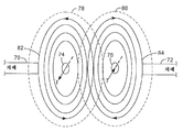
도 6은 좌측부(70) 및 우측부(72)가 도시된, 도전성 차폐로부터의 자기장에 대한 효과를 도시하는 측면 사시도이다. 명료성을 위해서, 단일-루프 안테나가 도전성 트레이스(trace)(74 및 76)로 도 6에 도시된다. 도전성 차폐의 효과와 관련해서, 2중-루프 안테나는 논리적으로, 2중-루프와 결합된 반지름들 간의 평균과 동일한 반지름을 갖는 단일-루프 안테나로서 보여질 수 있어야 한다. FIG. 6 is a side perspective view showing the effect on the magnetic field from the conductive shield, in which the
도 6에 도시된 바와 같이, 도전성 트레이스(74 및 76)내의 전류 I는 각 자기장(82 및 84)을 생성한다. 특히, 자기장(82 및 84)은, 좌측부(70) 및 우측부(72) 각각의 차폐 효과가 없으면, 영역(78, 80) 각각으로 확장할 것이다. 따라서, 도전성 트레이스(74 및 76)에 더 근접하게 좌측부(70) 및 우측부(72)를 배치하는 것은, 결과적 자기장이 형성되는 외부 범위를 더 제한하는 것으로 실현되어야 한다. 또한, 도전성 트레이스(74 및 76)에 더 근접하게 좌측부(70) 및 우측부(72)를 배치하는 것은, 반대쪽 도전성 트레이스 내부로 확장하는 필드(82, 84)까지 범위를 더 제한한다. 이 단일-루프 안테나의 전체 통신 영역은 대략적으로 자기장(82 및 84)의 합이 된다.As shown in FIG. 6, the current I in the conductive traces 74 and 76 creates respective
이러한 이유에서, D3(도 5)는 자기장(82 및 84)(도 6)이 중첩되기 위해 필요한 최소 거리를 초과하도록 선택되어, 필드 강도가 루프내에서 RFID 통신을 위해 충분하다는 것을 보장한다. For this reason, D3 (FIG. 5) is chosen to exceed the minimum distance required for the
일 실시예에서, 예를 들어, D3는 다음과 같이 D1 및 D2의 평균과 거의 동일하게 선택된다. In one embodiment, for example, D3 is chosen to be approximately equal to the average of D1 and D2 as follows.
![]()
![]()
또한, D2는 약 1.5*D1과 동일하게 선택된다. 예를 들어, D1, D2 및 D3는 각각 2˝(5.08cm), 3.5˝(8.89cm), 및 2.75˝(6.98cm)일 수 있다. 이렇게 특정하게 선택된 거리 D3은, 내부 루프(62) 및 외부 루프(64)(도 5)에 의해 생성된 결과적 자기장이, RFID 통신을 달성하기에 충분한 강도로서 안테나(60)를 전체적으로 커버하는 내부 및 외부 방향 모두로 이들 루프로부터 확장하도록 한다. Also, D2 is chosen to be equal to about 1.5 * D1. For example, D1, D2, and D3 may be 2 dB (5.08 cm), 3.5 mm (8.89 cm), and 2.75 mm (6.98 cm), respectively. This particular selected distance D3 is such that the resulting magnetic field generated by the
도 7은 도전성 차폐의 필드-정형 효과를 도시하는 또 다른 측면 사시도이다. 구체적으로, 도 7은, 좌측부(92A) 및 우측부(92B)가 도시된 도전성 차폐에 의해 정형화되고, 안테나(94)에 의해 생성된 결과적 전자기장(90)을 도시한다. 도시된 바와 같이, 도전성 차폐는 전자기장(90)이 안테나(94)로부터 외부로 확장하는 범위를 제한하고, 이에 따라, 정의된 통신 영역의 수평 에지를 벗어나 배치된 RFID 태그의 부적절한 판독을 방지한다. 7 is another side perspective view showing the field-shaping effect of the conductive shield. Specifically, FIG. 7 shows the resultant
도 8A는, 안테나(102) 및 도전성 차폐(104)가 표면(106) 아래에 장착되어 있는 체크-인/체크-아웃 영역(100)의 일 실시예의 측면을 도시하는 사시도이다. 이 예에서, 안테나(102) 및 도전성 차폐(104)는 표면(106) 위에 RFID 태그 통신 영역(107)을 생성한다. 표면(106)은 통신 영역의 에지를 식별하는 시각적 표 시(indicia)를 포함할 수 있다. 이러한 방식으로, 도전성 차폐(104)는, RFID 태그가 정의된 통신 영역(107)을 벗어난 영역(108)에서 부적절하게 판독되는 것을 방지한다. FIG. 8A is a perspective view showing the side of one embodiment of the check-in / check-out
도 8B는, 체크-인/체크-아웃 영역(110)의 다른 실시예의 측면을 도시하는 사시도이다. 이 예에서, 데스크탑(116)은 오목부(120)를 형성하고, 그 아래에 안테나(112)가 장착된다. 도전성 차폐(114)는 데스크탑(116)의 비-오목부상에 안테나(112)를 둘러싸도록 장착된다. 이 예에서, 안테나(112) 및 도전성 차폐(114)는 RFID 태그 통신 영역(117)을 생성하고, 도전성 차폐는, RFID 태그가 정의된 통신 영역을 벗어난 영역(118)에서 부적절하게 판독되는 것을 방지한다. 또 다른 실시예에서, 데스크탑(116)은 오목부(120)를 형성하지 않고, 안테나(112)는 데스크탑 아래에 장착된다. 8B is a perspective view illustrating the side of another embodiment of the check-in / check-out
본 발명의 다양한 실시예들이 설명되었다. 상기 및 기타 실시예들은 다음의 청구항의 범위내에 포함된다. Various embodiments of the invention have been described. Such and other embodiments are included within the scope of the following claims.
Claims (16)
Applications Claiming Priority (2)
| Application Number | Priority Date | Filing Date | Title |
|---|---|---|---|
| US10/784,109 | 2004-02-20 | ||
| US10/784,109 US7421245B2 (en) | 2004-02-20 | 2004-02-20 | Field-shaping shielding for radio frequency identification (RFID) system |
Publications (1)
| Publication Number | Publication Date |
|---|---|
| KR20070011314A true KR20070011314A (en) | 2007-01-24 |
Family
ID=34861405
Family Applications (1)
| Application Number | Title | Priority Date | Filing Date |
|---|---|---|---|
| KR1020067019228A KR20070011314A (en) | 2004-02-20 | 2005-01-07 | Field-shaping shielding for radio frequency indentification(rfid) system |
Country Status (15)
| Country | Link |
|---|---|
| US (1) | US7421245B2 (en) |
| EP (1) | EP1723697B1 (en) |
| JP (1) | JP2007523563A (en) |
| KR (1) | KR20070011314A (en) |
| CN (1) | CN1954462A (en) |
| AR (1) | AR047687A1 (en) |
| AT (1) | ATE417381T1 (en) |
| AU (1) | AU2005217933A1 (en) |
| BR (1) | BRPI0507833A (en) |
| CA (1) | CA2556932A1 (en) |
| DE (1) | DE602005011583D1 (en) |
| ES (1) | ES2317187T3 (en) |
| NZ (1) | NZ549370A (en) |
| TW (1) | TW200529737A (en) |
| WO (1) | WO2005083836A1 (en) |
Families Citing this family (36)
| Publication number | Priority date | Publication date | Assignee | Title |
|---|---|---|---|---|
| US7342496B2 (en) | 2000-01-24 | 2008-03-11 | Nextreme Llc | RF-enabled pallet |
| US8077040B2 (en) | 2000-01-24 | 2011-12-13 | Nextreme, Llc | RF-enabled pallet |
| JP3982476B2 (en) * | 2003-10-01 | 2007-09-26 | ソニー株式会社 | Communications system |
| JP4742546B2 (en) * | 2004-09-13 | 2011-08-10 | オムロン株式会社 | Goods conveying material |
| JP4667397B2 (en) * | 2005-01-17 | 2011-04-13 | 富士通株式会社 | Communication apparatus and communication method |
| US7884725B2 (en) * | 2006-06-21 | 2011-02-08 | Neology, Inc. | Systems and methods for stirring electromagnetic fields and interrogating stationary RFID tags |
| FR2904880B1 (en) * | 2006-08-11 | 2008-10-10 | Ask Sa | SECURITY DEVICE INTEGRATED WITH CONTACTLESS OBJECT OF SECURE DOCUMENT TYPE WITH RADIO FREQUENCY DEVICE. |
| JP5504894B2 (en) * | 2008-02-12 | 2014-05-28 | 日本電気株式会社 | Loop antenna and immunity test method |
| GB0802729D0 (en) * | 2008-02-14 | 2008-03-26 | Isis Innovation | Resonant reflector assembly and method |
| US8076593B2 (en) | 2008-03-28 | 2011-12-13 | David Centner | Apparatus and method for supporting and shielding a wireless device |
| US9515494B2 (en) | 2008-09-27 | 2016-12-06 | Witricity Corporation | Wireless power system including impedance matching network |
| US9160203B2 (en) | 2008-09-27 | 2015-10-13 | Witricity Corporation | Wireless powered television |
| US20100232132A1 (en) * | 2009-03-16 | 2010-09-16 | Highway Toll Administration, Llc | Flexible Transponder Holder |
| US8514059B2 (en) * | 2009-08-06 | 2013-08-20 | Highway Toll Administration, Llc | Transponder holder for controlling the operation of a transponder |
| US8353759B2 (en) | 2009-10-16 | 2013-01-15 | Igt | Shape control of magentic fields for table games |
| JP5378243B2 (en) * | 2010-01-13 | 2013-12-25 | アルプス電気株式会社 | INPUT DEVICE WITH ANTENNA AND ELECTRONIC DEVICE PROVIDED WITH THE DEVICE |
| US10977965B2 (en) | 2010-01-29 | 2021-04-13 | Avery Dennison Retail Information Services, Llc | Smart sign box using electronic interactions |
| AU2011210870A1 (en) | 2010-01-29 | 2012-08-16 | Avery Dennison Corporation | Smart sign box using electronic interactions |
| CN104025556B (en) | 2011-09-01 | 2018-08-10 | 艾利丹尼森公司 | Equipment, system and method for consumer's tracking |
| US8659494B2 (en) | 2011-11-07 | 2014-02-25 | Symbol Technologies, Inc. | Rotating-polarization reflector-backed RFID loop antenna apparatus and method |
| CN104025129B (en) * | 2012-09-10 | 2018-04-03 | 艾利丹尼森公司 | Method for preventing NFC labels unauthorized from shifting |
| EP2786304B1 (en) | 2012-10-18 | 2017-06-07 | Avery Dennison Corporation | Method, system and apparatus for nfc security |
| EP3429250A1 (en) | 2012-11-19 | 2019-01-16 | Avery Dennison Corporation | Nfc security system and method for disabling unauthorized tags |
| US9685994B2 (en) * | 2012-12-04 | 2017-06-20 | Samsung Electronics Co., Ltd. | Antenna for wireless power transmission and near field communication |
| US9165235B2 (en) | 2013-05-21 | 2015-10-20 | Garble, LLC | Method and apparatus for protecting information in magnetic strip and RFID cards from fraudulent scanning |
| US20150162957A1 (en) * | 2013-12-05 | 2015-06-11 | WaveMark, Inc. | Scanning station utilizing passive near-field communication RF coupling system for scanning RFID tags |
| FR3023983B1 (en) * | 2014-07-16 | 2017-12-08 | Oberthur Technologies | RFID TRANSPONDER ELECTRONIC ENTITY |
| KR20160063191A (en) * | 2014-11-26 | 2016-06-03 | 삼성전기주식회사 | Antenna device and Near field communication device including the same |
| FR3030908B1 (en) * | 2014-12-18 | 2016-12-09 | Stmicroelectronics Rousset | ANTENNA FOR ELECTRONIC DEVICE |
| JP6319464B2 (en) * | 2015-01-15 | 2018-05-09 | 株式会社村田製作所 | Antenna device and manufacturing method thereof |
| KR102405446B1 (en) * | 2015-08-10 | 2022-06-08 | 삼성전자주식회사 | Antenna device and electronic device |
| KR101754742B1 (en) * | 2016-02-29 | 2017-07-06 | 주식회사 알앤엠테크 | Casino chips reading apparatus in casino tables |
| DE102018112570A1 (en) * | 2018-05-25 | 2019-11-28 | Ebm-Papst Mulfingen Gmbh & Co. Kg | Device and method for sending and receiving data of a passive RFID tag |
| JP7123641B2 (en) | 2018-06-07 | 2022-08-23 | 株式会社東芝 | chip antenna |
| CN112639825B (en) * | 2018-06-27 | 2024-03-19 | 艾利丹尼森零售信息服务公司 | RFID tag resistant to operation in high frequency band of microwave oven |
| US20200364420A1 (en) * | 2019-05-17 | 2020-11-19 | Storeroom Logix, LLC | Autonomous rfid storage system |
Family Cites Families (21)
| Publication number | Priority date | Publication date | Assignee | Title |
|---|---|---|---|---|
| US4260990A (en) | 1979-11-08 | 1981-04-07 | Lichtblau G J | Asymmetrical antennas for use in electronic security systems |
| US4373163A (en) | 1980-07-14 | 1983-02-08 | I.D. Engineering, Inc. | Loop antenna for security systems |
| JP2528517Y2 (en) | 1990-11-21 | 1997-03-12 | 日本板硝子株式会社 | Window glass antenna |
| US5142292A (en) | 1991-08-05 | 1992-08-25 | Checkpoint Systems, Inc. | Coplanar multiple loop antenna for electronic article surveillance systems |
| US5404147A (en) | 1992-10-28 | 1995-04-04 | Sensormatic Electronics Corporation | EAS system loop antenna having three loops of different area |
| NZ283706A (en) | 1994-04-18 | 1997-02-24 | John Douglas Frank Finlayson | Flat polygonal antenna located vertically against a wall of a passageway, typically for monitoring cattle |
| AU3741497A (en) | 1996-07-29 | 1998-02-20 | Motorola, Inc. | Magnetic field antenna and method for field cancellation |
| US5914692A (en) | 1997-01-14 | 1999-06-22 | Checkpoint Systems, Inc. | Multiple loop antenna with crossover element having a pair of spaced, parallel conductors for electrically connecting the multiple loops |
| US5940043A (en) | 1997-02-21 | 1999-08-17 | Sensormatic Electronics Corporation | Unidirectional field antenna for identification system |
| CH691098A5 (en) * | 1997-03-24 | 2001-04-12 | Em Microelectronic Marin Sa | monolithic structure of integrated circuit and antenna coil provided with a peripheral protective ring. |
| US6285327B1 (en) * | 1998-04-21 | 2001-09-04 | Qualcomm Incorporated | Parasitic element for a substrate antenna |
| US5977875A (en) | 1998-08-31 | 1999-11-02 | Magnex Corporation | Collective objects management system using R.F. object indentification |
| US6147655A (en) | 1998-11-05 | 2000-11-14 | Single Chip Systems Corporation | Flat loop antenna in a single plane for use in radio frequency identification tags |
| US6714121B1 (en) * | 1999-08-09 | 2004-03-30 | Micron Technology, Inc. | RFID material tracking method and apparatus |
| WO2001026180A1 (en) | 1999-10-04 | 2001-04-12 | Amerasia International Technology, Inc. | Tamper-resistant wireless article including an antenna |
| US6307517B1 (en) * | 2000-06-13 | 2001-10-23 | Applied Wireless Identifications Group, Inc. | Metal compensated radio frequency identification reader |
| FR2824018B1 (en) | 2001-04-26 | 2003-07-04 | Arjo Wiggins Sa | COVER INCORPORATING A RADIOFREQUENCY IDENTIFICATION DEVICE |
| US20020180588A1 (en) | 2001-06-05 | 2002-12-05 | Erickson David P. | Radio frequency identification in document management |
| US6567050B1 (en) | 2001-12-17 | 2003-05-20 | Briggs James B | Loop antenna compensator |
| US7187288B2 (en) * | 2002-03-18 | 2007-03-06 | Paratek Microwave, Inc. | RFID tag reading system and method |
| US6700547B2 (en) * | 2002-04-12 | 2004-03-02 | Digital Angel Corporation | Multidirectional walkthrough antenna |
-
2004
- 2004-02-20 US US10/784,109 patent/US7421245B2/en not_active Expired - Fee Related
-
2005
- 2005-01-07 CN CNA2005800090098A patent/CN1954462A/en active Pending
- 2005-01-07 BR BRPI0507833-4A patent/BRPI0507833A/en not_active IP Right Cessation
- 2005-01-07 AU AU2005217933A patent/AU2005217933A1/en not_active Abandoned
- 2005-01-07 EP EP05705207A patent/EP1723697B1/en not_active Not-in-force
- 2005-01-07 WO PCT/US2005/000439 patent/WO2005083836A1/en active Search and Examination
- 2005-01-07 DE DE602005011583T patent/DE602005011583D1/en active Active
- 2005-01-07 JP JP2006554090A patent/JP2007523563A/en active Pending
- 2005-01-07 KR KR1020067019228A patent/KR20070011314A/en not_active Application Discontinuation
- 2005-01-07 NZ NZ549370A patent/NZ549370A/en unknown
- 2005-01-07 AT AT05705207T patent/ATE417381T1/en not_active IP Right Cessation
- 2005-01-07 ES ES05705207T patent/ES2317187T3/en active Active
- 2005-01-07 CA CA002556932A patent/CA2556932A1/en not_active Abandoned
- 2005-01-25 TW TW094102216A patent/TW200529737A/en unknown
- 2005-02-18 AR ARP050100590A patent/AR047687A1/en unknown
Also Published As
| Publication number | Publication date |
|---|---|
| BRPI0507833A (en) | 2007-07-10 |
| EP1723697A1 (en) | 2006-11-22 |
| DE602005011583D1 (en) | 2009-01-22 |
| CN1954462A (en) | 2007-04-25 |
| AU2005217933A1 (en) | 2005-09-09 |
| NZ549370A (en) | 2008-03-28 |
| JP2007523563A (en) | 2007-08-16 |
| AR047687A1 (en) | 2006-02-01 |
| ATE417381T1 (en) | 2008-12-15 |
| WO2005083836A1 (en) | 2005-09-09 |
| US20050186902A1 (en) | 2005-08-25 |
| CA2556932A1 (en) | 2005-09-09 |
| TW200529737A (en) | 2005-09-01 |
| ES2317187T3 (en) | 2009-04-16 |
| US7421245B2 (en) | 2008-09-02 |
| EP1723697B1 (en) | 2008-12-10 |
Similar Documents
| Publication | Publication Date | Title |
|---|---|---|
| US7417599B2 (en) | Multi-loop antenna for radio frequency identification (RFID) communication | |
| KR20070011314A (en) | Field-shaping shielding for radio frequency indentification(rfid) system | |
| US7591415B2 (en) | Passport reader for processing a passport having an RFID element | |
| US20090085750A1 (en) | Extended RFID tag | |
| US7268687B2 (en) | Radio frequency identification tags with compensating elements | |
| EP1086444B1 (en) | Identification tag with enhanced security | |
| AU2007219574B2 (en) | Arrangement comprising an object, which is at least partially composed of metal or noble metal, and an RFID identification apparatus | |
| MXPA06009459A (en) | Multi-loop antenna for radio frequency identification (rfid) communication | |
| MXPA06009458A (en) | Field-shaping shielding for radio frequency identification (rfid) system |
Legal Events
| Date | Code | Title | Description |
|---|---|---|---|
| WITN | Application deemed withdrawn, e.g. because no request for examination was filed or no examination fee was paid |