KR102589814B1 - Marker materials and forms for magnetic marker position determination (MLML) - Google Patents
Marker materials and forms for magnetic marker position determination (MLML) Download PDFInfo
- Publication number
- KR102589814B1 KR102589814B1 KR1020187000167A KR20187000167A KR102589814B1 KR 102589814 B1 KR102589814 B1 KR 102589814B1 KR 1020187000167 A KR1020187000167 A KR 1020187000167A KR 20187000167 A KR20187000167 A KR 20187000167A KR 102589814 B1 KR102589814 B1 KR 102589814B1
- Authority
- KR
- South Korea
- Prior art keywords
- magnetic
- marker
- anisotropy
- susceptibility
- ratio
- Prior art date
Links
Images


Classifications
-
- A—HUMAN NECESSITIES
- A61—MEDICAL OR VETERINARY SCIENCE; HYGIENE
- A61B—DIAGNOSIS; SURGERY; IDENTIFICATION
- A61B90/00—Instruments, implements or accessories specially adapted for surgery or diagnosis and not covered by any of the groups A61B1/00 - A61B50/00, e.g. for luxation treatment or for protecting wound edges
- A61B90/39—Markers, e.g. radio-opaque or breast lesions markers
-
- A—HUMAN NECESSITIES
- A61—MEDICAL OR VETERINARY SCIENCE; HYGIENE
- A61B—DIAGNOSIS; SURGERY; IDENTIFICATION
- A61B5/00—Measuring for diagnostic purposes; Identification of persons
- A61B5/05—Detecting, measuring or recording for diagnosis by means of electric currents or magnetic fields; Measuring using microwaves or radio waves
-
- A—HUMAN NECESSITIES
- A61—MEDICAL OR VETERINARY SCIENCE; HYGIENE
- A61B—DIAGNOSIS; SURGERY; IDENTIFICATION
- A61B5/00—Measuring for diagnostic purposes; Identification of persons
- A61B5/43—Detecting, measuring or recording for evaluating the reproductive systems
- A61B5/4306—Detecting, measuring or recording for evaluating the reproductive systems for evaluating the female reproductive systems, e.g. gynaecological evaluations
- A61B5/4312—Breast evaluation or disorder diagnosis
-
- H—ELECTRICITY
- H01—ELECTRIC ELEMENTS
- H01F—MAGNETS; INDUCTANCES; TRANSFORMERS; SELECTION OF MATERIALS FOR THEIR MAGNETIC PROPERTIES
- H01F1/00—Magnets or magnetic bodies characterised by the magnetic materials therefor; Selection of materials for their magnetic properties
- H01F1/01—Magnets or magnetic bodies characterised by the magnetic materials therefor; Selection of materials for their magnetic properties of inorganic materials
- H01F1/03—Magnets or magnetic bodies characterised by the magnetic materials therefor; Selection of materials for their magnetic properties of inorganic materials characterised by their coercivity
- H01F1/032—Magnets or magnetic bodies characterised by the magnetic materials therefor; Selection of materials for their magnetic properties of inorganic materials characterised by their coercivity of hard-magnetic materials
-
- H—ELECTRICITY
- H01—ELECTRIC ELEMENTS
- H01F—MAGNETS; INDUCTANCES; TRANSFORMERS; SELECTION OF MATERIALS FOR THEIR MAGNETIC PROPERTIES
- H01F1/00—Magnets or magnetic bodies characterised by the magnetic materials therefor; Selection of materials for their magnetic properties
- H01F1/01—Magnets or magnetic bodies characterised by the magnetic materials therefor; Selection of materials for their magnetic properties of inorganic materials
- H01F1/03—Magnets or magnetic bodies characterised by the magnetic materials therefor; Selection of materials for their magnetic properties of inorganic materials characterised by their coercivity
- H01F1/12—Magnets or magnetic bodies characterised by the magnetic materials therefor; Selection of materials for their magnetic properties of inorganic materials characterised by their coercivity of soft-magnetic materials
-
- A—HUMAN NECESSITIES
- A61—MEDICAL OR VETERINARY SCIENCE; HYGIENE
- A61B—DIAGNOSIS; SURGERY; IDENTIFICATION
- A61B17/00—Surgical instruments, devices or methods, e.g. tourniquets
- A61B2017/00831—Material properties
- A61B2017/00862—Material properties elastic or resilient
-
- A—HUMAN NECESSITIES
- A61—MEDICAL OR VETERINARY SCIENCE; HYGIENE
- A61B—DIAGNOSIS; SURGERY; IDENTIFICATION
- A61B90/00—Instruments, implements or accessories specially adapted for surgery or diagnosis and not covered by any of the groups A61B1/00 - A61B50/00, e.g. for luxation treatment or for protecting wound edges
- A61B90/39—Markers, e.g. radio-opaque or breast lesions markers
- A61B2090/3904—Markers, e.g. radio-opaque or breast lesions markers specially adapted for marking specified tissue
- A61B2090/3908—Soft tissue, e.g. breast tissue
-
- A—HUMAN NECESSITIES
- A61—MEDICAL OR VETERINARY SCIENCE; HYGIENE
- A61B—DIAGNOSIS; SURGERY; IDENTIFICATION
- A61B90/00—Instruments, implements or accessories specially adapted for surgery or diagnosis and not covered by any of the groups A61B1/00 - A61B50/00, e.g. for luxation treatment or for protecting wound edges
- A61B90/39—Markers, e.g. radio-opaque or breast lesions markers
- A61B2090/3925—Markers, e.g. radio-opaque or breast lesions markers ultrasonic
-
- A—HUMAN NECESSITIES
- A61—MEDICAL OR VETERINARY SCIENCE; HYGIENE
- A61B—DIAGNOSIS; SURGERY; IDENTIFICATION
- A61B90/00—Instruments, implements or accessories specially adapted for surgery or diagnosis and not covered by any of the groups A61B1/00 - A61B50/00, e.g. for luxation treatment or for protecting wound edges
- A61B90/39—Markers, e.g. radio-opaque or breast lesions markers
- A61B2090/3954—Markers, e.g. radio-opaque or breast lesions markers magnetic, e.g. NMR or MRI
-
- A—HUMAN NECESSITIES
- A61—MEDICAL OR VETERINARY SCIENCE; HYGIENE
- A61B—DIAGNOSIS; SURGERY; IDENTIFICATION
- A61B90/00—Instruments, implements or accessories specially adapted for surgery or diagnosis and not covered by any of the groups A61B1/00 - A61B50/00, e.g. for luxation treatment or for protecting wound edges
- A61B90/39—Markers, e.g. radio-opaque or breast lesions markers
- A61B2090/3966—Radiopaque markers visible in an X-ray image
-
- A—HUMAN NECESSITIES
- A61—MEDICAL OR VETERINARY SCIENCE; HYGIENE
- A61B—DIAGNOSIS; SURGERY; IDENTIFICATION
- A61B90/00—Instruments, implements or accessories specially adapted for surgery or diagnosis and not covered by any of the groups A61B1/00 - A61B50/00, e.g. for luxation treatment or for protecting wound edges
- A61B90/39—Markers, e.g. radio-opaque or breast lesions markers
- A61B2090/3987—Applicators for implanting markers
-
- A—HUMAN NECESSITIES
- A61—MEDICAL OR VETERINARY SCIENCE; HYGIENE
- A61B—DIAGNOSIS; SURGERY; IDENTIFICATION
- A61B90/00—Instruments, implements or accessories specially adapted for surgery or diagnosis and not covered by any of the groups A61B1/00 - A61B50/00, e.g. for luxation treatment or for protecting wound edges
- A61B90/39—Markers, e.g. radio-opaque or breast lesions markers
- A61B2090/3995—Multi-modality markers
-
- A—HUMAN NECESSITIES
- A61—MEDICAL OR VETERINARY SCIENCE; HYGIENE
- A61B—DIAGNOSIS; SURGERY; IDENTIFICATION
- A61B2562/00—Details of sensors; Constructional details of sensor housings or probes; Accessories for sensors
- A61B2562/02—Details of sensors specially adapted for in-vivo measurements
- A61B2562/0223—Magnetic field sensors
Landscapes
- Health & Medical Sciences (AREA)
- Life Sciences & Earth Sciences (AREA)
- Surgery (AREA)
- Engineering & Computer Science (AREA)
- Veterinary Medicine (AREA)
- Pathology (AREA)
- Biomedical Technology (AREA)
- Heart & Thoracic Surgery (AREA)
- Medical Informatics (AREA)
- Molecular Biology (AREA)
- Animal Behavior & Ethology (AREA)
- General Health & Medical Sciences (AREA)
- Public Health (AREA)
- Nuclear Medicine, Radiotherapy & Molecular Imaging (AREA)
- Physics & Mathematics (AREA)
- Biophysics (AREA)
- Oral & Maxillofacial Surgery (AREA)
- Radiology & Medical Imaging (AREA)
- Gynecology & Obstetrics (AREA)
- Reproductive Health (AREA)
- Power Engineering (AREA)
- Chemical & Material Sciences (AREA)
- Dispersion Chemistry (AREA)
- Medicines Containing Antibodies Or Antigens For Use As Internal Diagnostic Agents (AREA)
- Measurement And Recording Of Electrical Phenomena And Electrical Characteristics Of The Living Body (AREA)
- Materials For Medical Uses (AREA)
- Magnetic Treatment Devices (AREA)
- Magnetic Resonance Imaging Apparatus (AREA)
- Hard Magnetic Materials (AREA)
- Soft Magnetic Materials (AREA)
- Media Introduction/Drainage Providing Device (AREA)
- Geophysics And Detection Of Objects (AREA)
- Ropes Or Cables (AREA)
- Measurement Of Length, Angles, Or The Like Using Electric Or Magnetic Means (AREA)
Abstract
본 발명은 신체 내의 조직 내의 부위를 표지하기 위한 자성 표지자에 관한 것이다. 하나의 실시예에서, 표지자는 자성 금속 유리를 포함한다. 다른 실시예에서, 표지자는 9보다 더 작은 비등방성 비율을 갖는 비구형 구성이다. 또 다른 실시예에서, 표지자는 6보다 더 작은 비등방성 비율을 갖는 비구형 구성이다. 또 다른 실시예에서, 표지자는 3보다 더 작은 비등방성 비율을 갖는 비구형 구성이다.The present invention relates to a magnetic marker for marking a region within a tissue within the body. In one embodiment, the marker comprises a magnetic metallic glass. In another embodiment, the marker is a non-spherical configuration with an anisotropy ratio less than 9. In another embodiment, the marker is a non-spherical configuration with an anisotropy ratio less than 6. In another embodiment, the marker is a non-spherical configuration with an anisotropy ratio less than 3.
Description
관련 출원Related applications
본 출원은 본원에서 전체적으로 참조로 통합된, 2015년 6월 4일자로 출원된 미국 가특허 출원 제62/170,768호에 기초하여 우선권을 주장한다.This application claims priority based on U.S. Provisional Patent Application No. 62/170,768, filed June 4, 2015, which is hereby incorporated by reference in its entirety.
본 발명은 대체로 의학적 검출을 위한 표지자, 및 더 구체적으로 자성 의료 표지자에 관한 것이다.The present invention relates generally to markers for medical detection, and more particularly to magnetic medical markers.
유방 촬영술 스크리닝 프로그램의 보급이 증가함에 따라, 대부분의 유방암은 유방 보존적 치료를 위해 교정 가능한, 작고 촉진 불가능한 (또는 잠재성) 병변으로서 검출된다. 촉진 불가능한 유방암의 정확한 위치 결정은 적절한 여유와 함께 완전한 종양의 외과적 제거를 허용하기 위해 핵심적이다. 종양이 완전하게 절제되지 않으면, 환자는 임의의 잔여 암 조직을 제거하기 위한 추가의 수술을 받을 필요가 있다. 정확한 위치 결정은 또한 부정적인 미용적 결과를 야기할 수 있는 과도한 유방 조직의 절제를 회피하는 것을 돕는다. 정확한 위치 결정은 직장, 전립선, 및 폐와 같은 다른 암과, 본 기술 분야의 통상의 기술자에 의해 공지된 다른 질환에 의해 요구된다.With the increasing prevalence of mammography screening programs, most breast cancers are detected as small, non-palpable (or occult) lesions that are correctable for breast-conserving treatment. Accurate localization of nonpalpable breast cancer is key to allow surgical removal of the complete tumor with adequate margins. If the tumor is not completely resected, the patient may need to undergo additional surgery to remove any remaining cancerous tissue. Accurate positioning also helps avoid excision of excess breast tissue, which can lead to negative cosmetic results. Accurate localization is required by other cancers such as rectal, prostate, and lung, and other diseases known to those skilled in the art.
수술 중의 촉진 불가능한 병변의 위치 결정을 위한 현재의 최적 표준은 와이어 안내식 위치 결정(WGL: Wire-Guided Localization)이다. 이러한 기술이 널리 사용되지만, WGL은 다수의 단점을 갖는다. 첫째로, 이는 2개의 분리된 절차를 포함하며, 방사선과와 외과 사이에서 수송 및 스케줄링의 문제점을 제시할 수 있다. 둘째로, 안내 와이어의 위치 설정은 이후의 수술에서 원하는 미용적 결과를 달성하기 위해 최적이 아닐 수 있다. 셋째로, 후크 와이어는 병변의 부위로부터 이동하거나, 유방 촬영술 동안 또는 환자를 이동시키는 동안 변위될 수 있다. 넷째로, 와이어의 삽입은 환자에게 고통스러울 수 있고, 마지막으로, 감염의 위험은 수술이 보통 와이어 삽입과 동일한 날에 이루어질 필요가 있음을 의미한다.The current gold standard for intraoperative localization of nonpalpable lesions is wire-guided localization (WGL). Although this technology is widely used, WGL has a number of drawbacks. First, it involves two separate procedures and may present transportation and scheduling problems between radiology and surgery. Second, positioning of the guide wire may be suboptimal to achieve the desired cosmetic result in subsequent surgeries. Third, the hook wire may move away from the site of the lesion or become displaced during mammography or while moving the patient. Fourthly, the insertion of the wire can be painful for the patient, and finally, the risk of infection means that the surgery usually needs to take place on the same day as the wire insertion.
이러한 단점을 극복하기 위해, 다른 위치 결정 기술이 개발되었다. 하나의 그러한 기술은 종양 내로 주입되어 휴대형 감마 프로브에 의해 검출되는 방사성 추적자를 사용하는 방사선 안내식 잠재성 병변 위치 결정(ROLL: Radioguided Occult Lesion Localization)이다. 이것이 WGL의 운송의 복잡성을 제거하지만, 이러한 기술은 특수한 취급 및 폐기 절차를 요구하는, 방사능 재료의 사용의 결점을 도입한다.To overcome these shortcomings, other positioning techniques have been developed. One such technique is Radioguided Occult Lesion Localization (ROLL), which uses a radioactive tracer injected into the tumor and detected by a handheld gamma probe. Although this eliminates the complexity of transport of WGL, this technology introduces the drawback of the use of radioactive materials, which require special handling and disposal procedures.
자성 표지자가 또한 사용되고, 이는 표지자로서 방사능 재료를 사용함으로써 발생하는 불편함 및 수송의 문제를 극복하고, 이는 또한 안내 와이어의 결점을 회피한다. 그러나, 자성 표지자는 안내 와이어와 비교하여 제조하기가 상대적으로 복잡하다.Magnetic markers are also used, which overcome the inconvenience and transportation problems arising from the use of radioactive materials as markers, and they also avoid the drawbacks of guide wires. However, magnetic markers are relatively complex to manufacture compared to guide wires.
안내 와이어 및 자성 표지자를 포함하는 모든 공지된 표지 장치가 중공 니들 또는 캐뉼라를 통해 도입된다. 환자 불편함을 최소화하기 위해, 이러한 니들은 전형적으로 직경이 좁다. 니들의 작은 직경은 표지자 단면을 구속한다. 종래의 생검 니들에 대해, 이러한 치수는 대체로 14 내지 18게이지이다. 이는 니들이 대체로 0.8mm 내지 1.5mm의 내경을 갖지만, 소정의 니들 설계에 대해 가능하게는 1.8mm만큼 클 수 있음을 의미한다. 진공 보조식 니들이 사용되면, 니들 크기는 전형적으로 2.3 내지 2.5mm의 내경을 갖는, 11게이지이다. 따라서, 자성 표지자는 전형적으로 직경이 1.5mm보다 더 작게 구속된다. 실질적으로, 이러한 크기 구속은 자성 응답과, 결국 표지자가 자성 프로브에 의해 위치 결정될 수 있는 용이성을 제한한다. 그러므로, 더 강한 자성 응답이 필요하다.All known labeling devices, including guide wires and magnetic markers, are introduced via hollow needles or cannulae. To minimize patient discomfort, these needles are typically narrow in diameter. The small diameter of the needle constrains the marker cross section. For conventional biopsy needles, these dimensions are typically 14 to 18 gauge. This means that the needle typically has an internal diameter of 0.8 mm to 1.5 mm, but could possibly be as large as 1.8 mm for a given needle design. If vacuum assisted needles are used, the needle size is typically 11 gauge, with an internal diameter of 2.3 to 2.5 mm. Accordingly, magnetic markers are typically confined to less than 1.5 mm in diameter. In practice, these size constraints limit the magnetic response and, consequently, the ease with which the marker can be positioned by the magnetic probe. Therefore, a stronger magnetic response is needed.
자성 생검 표지자에 대한 다른 문제는 유효 자성 응답을 달성하기 위해서는, 재료의 체적이 최대화될 필요가 있는 것이다. 이러한 체적 요건은 그의 직경보다 상당히 더 큰 길이를 갖는 전형적인 형상의 표지자의 결과를 낳는다. 그러한 표지자는 1mm 내지 12mm의 영역 내에 있고, 길이 대 직경비는 5보다 더 크다. 이러한 종횡비는 표지자 장축이 프로브와 직선일 때 얻어지는 훨씬 더 강한 신호 및 표지자 장축이 프로브에 대해 횡방향일 때의 더 약한 신호를 갖는 불균일한 자성 응답의 결과를 낳는다. 더 균일한 응답이 대체로 필요하다.Another problem with magnetic biopsy markers is that to achieve an effective magnetic response, the volume of material needs to be maximized. This volume requirement results in a marker of typical shape having a length significantly greater than its diameter. Such markers are in the region of 1 mm to 12 mm and have a length to diameter ratio greater than 5. This aspect ratio results in an uneven magnetic response, with a much stronger signal obtained when the marker long axis is straight to the probe and a weaker signal obtained when the marker long axis is transverse to the probe. A more uniform response is usually needed.
아울러, 표지자는 대체로 초음파 또는 정위 x-선 촬영 하에서 그의 위치로 안내되고 제 위치에 있는 것이 확인된다. 이는 표지자가 X-선 및 초음파 촬영 하에서, 그리고 바람직하게는 이러한 목적으로 사용될 수 있는 MRI 하에서, 선명하게 가시적인 것이 바람직함을 의미한다.In addition, the marker is usually guided to its location under ultrasound or stereotactic x-ray imaging and confirmed to be in place. This means that it is desirable for the marker to be clearly visible under X-rays and ultrasonography, and preferably under MRI, which can be used for this purpose.
(특허문헌 1) US 2015/0078535 A1 (2015. 03. 19.)
(특허문헌 2) US 2013/0253550 A1 (2013. 09. 26.)
(특허문헌 3) US 2003/0105394 A1 (2003. 06. 06.)
(특허문헌 4) US 2008/0091120 A1 (2008. 04. 17.)(Patent Document 1) US 2015/0078535 A1 (2015. 03. 19.)
(Patent Document 2) US 2013/0253550 A1 (2013. 09. 26.)
(Patent Document 3) US 2003/0105394 A1 (2003. 06. 06.)
(Patent Document 4) US 2008/0091120 A1 (2008. 04. 17.)
검출 가능한 신호의 강도를 감소시키지 않고서 소량의 재료를 가지며, 자성 프로브에 대한 임의의 방향으로부터 더 균일한 응답을 제공하는 표지자가 필요하다.What is needed is a marker that has a small amount of material without reducing the intensity of the detectable signal, and that provides a more uniform response from any direction relative to the magnetic probe.
본 발명은 이러한 필요를 해결한다.The present invention addresses this need.
본 발명은 외과적 사용을 위한 자성 표지자에 관한 것이다. 특히, 본 발명은 전개 이전의 그의 기하학적 형상으로부터 예상되는 것보다, 전개되면 더 균일한 자성 응답을 갖는 자성 표지자에 관한 것이다.The present invention relates to magnetic markers for surgical use. In particular, the present invention relates to magnetic markers that have a more uniform magnetic response when deployed than would be expected from their geometry prior to deployment.
하나의 양태에서, 표지자가 더 균일한 자성 응답을 제공하도록 선택된 형상을 갖는 표지자가 제공된다.In one aspect, a marker is provided having a shape selected such that the marker provides a more uniform magnetic response.
다른 양태에서, 표지자가 더 균일한 자성 응답을 제공하도록, 전개되면 변화하는 기하학적 구성을 갖는 표지자가 제공된다.In another aspect, a marker is provided that has a geometric configuration that changes as it unfolds, such that the marker provides a more uniform magnetic response.
다른 양태에서, 표지자가 전개 이전의 그의 기하학적 형상으로부터 예상되는 것보다 더 균일한 자성 응답을 제공하도록 선택된 재료 조성을 갖는 표지자가 제공된다.In another aspect, a marker is provided having a material composition selected such that the marker provides a more uniform magnetic response than expected from its geometry prior to deployment.
하나의 양태에서, 표지자는 9보다 더 작은 자성 감수율의 비등방성의 비율을 갖는 비구형 구성이다. 또 다른 실시예에서, 표지자는 6보다 더 작은 자성 감수율의 비등방성의 비율을 갖는 비구형 구성이다. 또 다른 실시예에서, 표지자는 3보다 더 작은 자성 감수율의 비등방성의 비율을 갖는 비구형 구성이다. 하나의 실시예에서, 비구형 표지자 구성은 실린더, 케이블, "아령형" 형태, 비드, 및 실뭉치(ball of yarn)를 포함하는 그룹으로부터 선택된 형상이다. 다른 실시예에서, 실린더는 조직 내에서의 배치 시에 구부러진다. 또 다른 실시예에서, 비구형 구성은 다면형이다.In one embodiment, the marker is a non-spherical configuration with a ratio of anisotropy to magnetic susceptibility less than 9. In another embodiment, the marker is a non-spherical configuration with a ratio of anisotropy to magnetic susceptibility less than 6. In another embodiment, the marker is a non-spherical configuration with a ratio of anisotropy to magnetic susceptibility less than 3. In one embodiment, the non-spherical marker configuration is a shape selected from the group including cylinders, cables, “dumbbell” shapes, beads, and balls of yarn. In another embodiment, the cylinder is bent upon placement within tissue. In another embodiment, the non-spherical configuration is polyhedral.
하나의 실시예에서, 표지자는 부위 내에서의 배치 시에 컴팩트한 가요성 비자성 구성요소들에 의해 연결된 복수의 자성 구성요소들을 포함하는, 신체 내의 조직 내의 부위를 표지하기 위한 자성 표지자이다. 다른 실시예에서, 신체 내의 조직 내의 부위를 표지하기 위한 자성 표지자는 제2 형상의 비자성 매트릭스 내에 위치된 제1 형상의 자성 구성요소를 포함한다. 또 다른 실시예에서, 신체 내의 조직 내의 부위를 표지하기 위한 자성 표지자는 자성 재료 외피 내의 자성 재료 코어를 포함한다. 또 다른 실시예에서, 코어 및 외피 중 하나는 연자성 재료이다.In one embodiment, the marker is a magnetic marker for labeling a site within a tissue within the body, comprising a plurality of magnetic components connected by flexible non-magnetic components that are compact when placed within the site. In another embodiment, a magnetic marker for labeling a site in tissue within the body includes a first shape of magnetic component positioned within a second shape of non-magnetic matrix. In another embodiment, a magnetic marker for labeling a site within a tissue within the body includes a core of magnetic material within a shell of magnetic material. In another embodiment, one of the core and shell is a soft magnetic material.
하나의 실시예에서, 신체 내의 조직의 부위를 표지하기 위한 자성 표지자는 신체 내로의 표지자의 배치 이후에 자성 표지자로 스스로 조립되는 복수의 자성 구성요소들을 포함한다. 다른 실시예에서, 자성 구성요소들은 각각 초소수성 코팅 내에 봉입된다. 또 다른 실시예에서, 신체 내의 조직 내의 부위를 표지하기 위한 자성 표지자는 자성 금속 유리를 포함한다.In one embodiment, a magnetic marker for labeling a portion of tissue within the body includes a plurality of magnetic components that self-assemble into a magnetic marker following placement of the marker into the body. In another embodiment, the magnetic components are each encapsulated within a superhydrophobic coating. In another embodiment, a magnetic marker for labeling a site within a tissue within the body comprises a magnetic metallic glass.
본 발명의 구조 및 기능이 첨부된 도면과 관련하여 본원의 설명으로부터 가장 잘 이해될 수 있다. 도면은 반드시 축척에 맞지는 않고, 대신에 대체로 예시적인 원리에 대해 강조된다. 도면은 모든 양태에서 예시적으로 간주되어야 하고, 범주가 청구범위에 의해서만 한정되는 본 발명을 제한하도록 의도되지 않는다.The structure and function of the present invention can be best understood from the description herein in conjunction with the accompanying drawings. The drawings are not necessarily to scale, but instead emphasis is generally placed on illustrative principles. The drawings are to be regarded in all respects as illustrative and are not intended to limit the invention, the scope of which is limited only by the claims.
도 1의 a) 및 도 1의 b)는 각각 연자성 재료 및 강자성 재료에 대한 자화 곡선이다.
도 2a는 표지자 굽힘각의 표지자의 감수율의 비등방성에 대한 영향의 그래프이다.
도 2b는 표지자의 자성 비등방성을 측정하기 위한 시험 장치의 일 실시예의 도면이다.
도 2c는 다양한 사잇각을 구비한 5mm 철(99.5%) 표지자로부터의 일정한 거리에서의 신호이고, 여기서 180°는 직선 실린더이고, 0°는 U-형상이다.
도 2d는 다양한 사잇각을 구비한 7mm 다중 스트랜드 스테인리스강 표지자로부터의 일정한 거리에서의 신호의 그래프이고, 여기서 180°는 직선 실린더이고, 0°는 U-형상이다.
도 3의 a)는 "로젠지(lozenge)" 또는 "비드"의 형태의 본 발명의 일 실시예의 도면이다.
도 3의 b) 및 도 3의 c)는 형상화된 단부를 구비한 자성 비드의 단면이다.
도 4의 a) - 도 4의 d)는 "아령" 형상의 형태의 본 발명의 실시예들의 도면이다.
도 5의 a) 및 도 5의 b)는 케이블 형태의 본 발명의 실시예들의 단면의 도면이다.
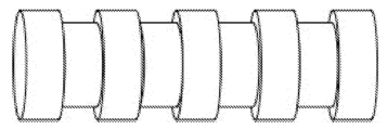
도 6a 및 도 6b는 "실뭉치"의 형상의 본 발명의 일 실시예의 도면이다.
도 7은 "초롱(chinese lantern)"의 형상의 본 발명의 일 실시예의 도면이다.
도 8a - 도 8g는 힌지형 링크를 구비한 본 발명의 실시예들의 도면이다.
도 9는 증가된 개수의 면을 갖는 본 발명의 표지자의 실시예들의 단면의 여러 도면이다.
도 10은 코어 및 외피의 형태의 본 발명의 일 실시예의 단면의 도면이다.
도 11은 외피 및 복수의 코어를 갖는 본 발명의 일 실시예의 도면이다.
도 12a 및 도 12b는 세그먼트형 표지자로서의 본 발명의 실시예들의 도면이다.
도 13a, 도 13b, 및 도 13c는 자성 재료의 형상과 표지자의 외부 형상이 상이한 본 발명의 실시예들의 도면이다.
도 14a - 도 14e는 다양한 재료로 만들어진 힌지를 구비한 형상화된 표지자의 형태의 본 발명의 실시예들의 도면이다.
도 15는 자가 조립에 의해 구성된 본 발명의 일 실시예의 도면이다.
도 16은 소수성 자가 조립에 의해 구성된 본 발명의 일 실시예의 도면이다.
도 17a 및 도 17b는 자가 조립에 의해 구성된 본 발명의 다른 실시예들의 도면이다.
도 18은 2개의 인터로킹 U 형상 표지자들의 일 실시예의 도면이다.Figure 1 a) and Figure 1 b) are magnetization curves for soft magnetic material and ferromagnetic material, respectively.
Figure 2a is a graph of the influence of marker bending angle on the anisotropy of marker susceptibility.
Figure 2b is a diagram of an embodiment of a test device for measuring magnetic anisotropy of a marker.
Figure 2c shows the signal at constant distance from a 5 mm iron (99.5%) marker with various included angles, where 180° is a straight cylinder and 0° is a U-shape.
Figure 2D is a graph of the signal at constant distance from a 7 mm multi-strand stainless steel marker with various angles, where 180° is a straight cylinder and 0° is a U-shape.
Figure 3 a) is a diagram of one embodiment of the invention in the form of a “lozenge” or “bead”.
Figure 3b) and Figure 3c) are cross-sections of a magnetic bead with a shaped end.
Figures 4 a) - Figure 4 d) are drawings of embodiments of the invention in the form of a "dumbbell" shape.
Figure 5 a) and Figure 5 b) are cross-sectional views of embodiments of the present invention in the form of a cable.
6A and 6B are diagrams of one embodiment of the present invention in the shape of a “ball of yarn”.
Figure 7 is a drawing of one embodiment of the invention in the shape of a “chinese lantern”.
8A-8G are diagrams of embodiments of the invention with hinged links.
Figure 9 is several views of cross-sections of embodiments of markers of the invention with an increased number of faces.
Figure 10 is a cross-sectional view of one embodiment of the invention in the form of a core and shell.
Figure 11 is a diagram of one embodiment of the present invention having a shell and a plurality of cores.
12A and 12B are diagrams of embodiments of the present invention as segmented markers.
13A, 13B, and 13C are diagrams of embodiments of the present invention in which the shape of the magnetic material and the external shape of the marker are different.
14A-14E are diagrams of embodiments of the invention in the form of shaped markers with hinges made of various materials.
Figure 15 is a diagram of an embodiment of the present invention constructed by self-assembly.
Figure 16 is a diagram of an embodiment of the present invention constructed by hydrophobic self-assembly.
17A and 17B are diagrams of other embodiments of the present invention constructed by self-assembly.
Figure 18 is a diagram of one embodiment of two interlocking U-shaped markers.
영구 자석으로서 자성 표지자를 만들기 위한 방법이 미국 특허 제6,173,715호에 설명되어 있다. 영구 자석 임플란트는 그가 주변의 임의의 자성 물질을 끌어당기고, 그러므로 다른 임플란트와 바람직하지 않게 상호 작용하거나, 예를 들어, 자성 재료로부터 만들어진 수술 도구가 인근에 있을 때, 조직 내에서 이동할 수 있는 결점을 갖는다.A method for making magnetic markers as permanent magnets is described in U.S. Patent No. 6,173,715. Permanent magnetic implants have the drawback that they attract any magnetic material around them and can therefore interact undesirably with other implants or migrate within tissues, for example when surgical instruments made from magnetic materials are nearby. have
생분해성 형태의 초상자성 산화철(SPIO: SuperParamagnetic Iron Oxide) 나노 입자로부터 형성된 표지자를 만들기 위한 방법이 미국 특허 출원 공개 제2014/0314679호에 설명되어 있다. SPIO 입자는 그러한 재료가 잔류 자기를 갖지 않고, 자체적으로 자성이 아니지만, 자기장의 존재 시에만 자화되기 때문에, 영구 자성 표지자에 대해 발생하는 우려를 회피한다. 이러한 SPIO 자성 표지자의 검출 및 위치 결정은 미국 특허 출원 공개 제2011/0133730호에 개시되어 있는 바와 같이, 표지자를 자기적으로 여기시키기 위한 교번 자기장을 발생시키고, 표지자에 의해 발생되는 자기장 신호를 검출하는 민감한 자력계 (또는 감수율 측정기)에 의해 수행될 수 있다.A method for making markers formed from biodegradable superparamagnetic iron oxide (SPIO) nanoparticles is described in US Patent Application Publication No. 2014/0314679. SPIO particles avoid concerns that arise with permanent magnetic markers because such materials have no residual magnetism and are not magnetic in themselves, but only become magnetized in the presence of a magnetic field. Detection and positioning of the SPIO magnetic marker, as disclosed in U.S. Patent Application Publication No. 2011/0133730, involves generating an alternating magnetic field to magnetically excite the marker and detecting the magnetic field signal generated by the marker. This can be performed by a sensitive magnetometer (or susceptibility meter).
자성 생검 표지자에 대한 다른 문제는 유효 자성 응답을 달성하기 위해서는, 재료의 체적이 최대화될 필요가 있는 것이다. 이러한 요건은 표지자가 니들을 통해 전달되어야 하고, 더 작은 니들 게이지(직경)가 환자에 대해 덜 고통스럽기 때문에, 직경보다 상당히 더 큰 길이를 갖는 전형적인 표지자의 결과를 낳는다. 그러한 표지자는 1mm 내지 12mm의 영역 내에 있고, 길이 대 직경비는 5보다 더 크다. 실질적으로, 그러한 크기 구속은 자성 응답과, 결국 표지자가 자성 프로브에 의해 위치 결정될 수 있는 용이성을 제한한다. 그러므로, 더 강한 응답이 필요하다.Another problem with magnetic biopsy markers is that to achieve an effective magnetic response, the volume of material needs to be maximized. This requirement results in a typical marker having a length significantly greater than its diameter, since the marker must be delivered through a needle and a smaller needle gauge (diameter) is less painful to the patient. Such markers are in the region of 1 mm to 12 mm and have a length to diameter ratio greater than 5. In practice, such size constraints limit the magnetic response and, consequently, the ease with which the marker can be positioned by a magnetic probe. Therefore, a stronger response is needed.
아울러, 표지자는 대체로 초음파 또는 정위 x-선 촬영 하에서 그의 위치로 안내되고 제 위치에 있는 것이 확인된다. 이는 표지자가 X-선 및 초음파 촬영 하에서, 그리고 바람직하게는 이러한 목적으로 사용될 수도 있는 MRI 하에서, 선명하게 가시적인 것이 바람직함을 의미한다. SPIO 입자는 X-선 촬영 하에서 제한된 가시성을 갖지만, 반향성 재료, 예를 들어, 중합체의 매트릭스 내에 그를 조합함으로써 초음파 가시적으로 만들어질 수 있다. 자성 표지자가 안내 와이어 및 방사능 접근의 결점을 극복하지만, 좁은 니들을 통해 도입될 수 있으며, 강한 자성 응답을 제공하고, X-선 및 초음파 촬영 하에서 가시적이고, 간단하게 제조될 수 있는 자성 표지자에 대한 필요가 남아 있다.In addition, the marker is usually guided to its location under ultrasound or stereotactic x-ray imaging and confirmed to be in place. This means that it is desirable for the marker to be clearly visible under X-rays and ultrasonography, and preferably under MRI, which may also be used for this purpose. SPIO particles have limited visibility under X-ray imaging, but can be made ultrasonically visible by assembling them within a matrix of an echogenic material, such as a polymer. Although magnetic markers overcome the drawbacks of guide wire and radiological approaches, they can be introduced through narrow needles, provide a strong magnetic response, are visible under X-rays and ultrasonography, and can be manufactured simply. The need remains.
표지자가 자기적으로 위치 결정 가능하기 위한 요건은 이식된 재료로부터의 소정의 자성 응답을 요구하고, 이러한 응답이 재료로부터 제거된 일정 거리에서 측정 가능하도록 요구한다. 이러한 응답은 자성 감수율 파라미터에 관련된다. SI 단위에서, 자성 감수율은 인가된 자기장에 응답하여 재료 내에서 유도되는 자화도를 표시하는 무차원 비례 상수이고, 다음에 의해 정의된다:The requirement for a marker to be magnetically localizable requires some magnetic response from the implanted material and that this response be measurable at some distance removed from the material. This response is related to the magnetic susceptibility parameter. In SI units, magnetic susceptibility is a dimensionless proportionality constant that describes the degree of magnetization induced within a material in response to an applied magnetic field, and is defined by:
![]()
![]()
여기서, M은 미터당 암페어로 측정된, 재료의 자화도(단위 체적당 자성 쌍극자 모멘트)이고, H는 미터당 암페어로 측정된, 자기장 강도이고, χ는 무차원 비례 상수인 자성 감수율이다. 엄격하게 말하자면, χ는 단지 상자성 또는 반자성 재료에 대한 일정하지만, 자기 이력 효과가 작은 연자성 또는 초상자성 재료에서, 그리고 재료를 자기적으로 포화시키기 위해 요구되는 장보다 훨씬 더 작은 인가되는 장(H)에 대해, 선형 관계인 M = χH는 양호한 근사화이다.where M is the magnetization (magnetic dipole moment per unit volume) of the material, measured in amperes per meter, H is the magnetic field strength, measured in amperes per meter, and χ is the magnetic susceptibility, which is a dimensionless proportionality constant. Strictly speaking, χ is only constant for paramagnetic or diamagnetic materials, but in soft or superparamagnetic materials where magnetic hysteresis effects are small, and the applied field (H) is much smaller than the field required to magnetically saturate the material. ), the linear relationship M = χH is a good approximation.
자성 감수율은 페러데이(Faraday) 균형, 구이(Gouy) 균형, 자기 공명 방법, 및 SQUID 자력계에 의한 유도적 방법을 포함한, 일정 범위의 공지된 방법에 의해 측정될 수 있다. 자성 감수율은 또한 균질장 내에서 표지자를 모델링하고 자성 감수율에 대응하는 표지자에 기인하는 왜곡을 측정함으로써, 앤시스 맥스웰(ANSYS Maxwell: 미국 펜실베이니아주 캐논스버그 소재의 앤시스 인크.(ANSYS Inc.))과 같은 컴퓨터 기반 유한 요소 자성 모델링 패키지를 사용하여 계산될 수 있다. 예를 들어, ["Magnetic Susceptibility Modelling Using ANSYS", K. Bartusek et al., Progress In Electromagnetics Research Symposium Proceedings, Marrakesh, Morocco, Mar. 20-23, 2011]에 설명되어 있는 방법 참조.Magnetic susceptibility can be measured by a range of known methods, including Faraday balance, Gouy balance, magnetic resonance methods, and inductive methods with SQUID magnetometers. Magnetic susceptibility can also be measured by modeling the marker in a homogeneous field and measuring the distortion due to the marker corresponding to the magnetic susceptibility (ANSYS Maxwell: ANSYS Inc., Canonsburg, PA, USA). ) can be calculated using a computer-based finite element magnetic modeling package such as For example, ["Magnetic Susceptibility Modeling Using ANSYS", K. Bartusek et al., Progress In Electromagnetics Research Symposium Proceedings, Marrakesh, Morocco, Mar. 20-23, 2011].
주어진 재료에 대해, 재료의 단위 질량당 유도되는 자성 응답인 자성 질량 감수율이 정의될 수 있다. 자성 질량 감수율, χρ = k/ρ, 여기서, ρ는 재료의 밀도이고, χρ는 m3/kg의 단위를 갖는다. 이는 정규화된 감수율이고, 상이한 재료들의 상대 감수율들이 비교되도록 허용한다. 예를 들어, 생검 표지자에 대한 표준 재료인 316 스테인리스강의 자성 질량 감수율은 대략 3.80 x l0-7 내지 1.27 x l0-6의 범위를 갖고, 영구 네오디뮴 자석은 대략 6.67 x l0-6의 값을 갖고, 초상자성 산화철(SPIO)계 표지자는 매트릭스 내의 입자의 밀도에 의존하여 대략 2.5 x lO-5 - 1.O x lO-3의 값을 갖지만, NiZn-페라이트는 대략 3 x 10⁻³ 내지 1.22 x 10⁻¹의 범위를 갖는다. 그러므로, NiZn-페라이트는 SPIO보다 더 적은 재료가 검출되도록 요구하고, 이는 결국 영구 네오디뮴 자성 재료 또는 316 스테인리스강보다 더 적은 재료를 요구한다.For a given material, the magnetic mass susceptibility can be defined, which is the magnetic response induced per unit mass of the material. Magnetic mass susceptibility, χ ρ = k/ρ, where ρ is the density of the material, and χ ρ has units of m 3 /kg. This is a normalized susceptibility rate and allows the relative susceptibility rates of different materials to be compared. For example, the magnetic mass susceptibility of 316 stainless steel, a standard material for biopsy markers, ranges from approximately 3.80 x l0 -7 to 1.27 x l0 -6 , while permanent neodymium magnets have a value of approximately 6.67 x l0 -6 , The superparamagnetic iron oxide ( SPIO) marker has a value of approximately 2.5 It has a range of -1 . Therefore, NiZn-ferrite requires less material to be detected than SPIO, which in turn requires less material than permanent neodymium magnetic material or 316 stainless steel.
선형 감수율 영역 내에서 장(H)을 받는, 체적(V)의 연자성 표지자에 대해, 표지자 상의 총 유도 모멘트는 m = MV = χVH일 것이다. 이러한 모멘트는 표지자로부터 제거된 거리에서, 등가의 점 쌍극자 모멘트에 의한 것으로서 근사화될 수 있는 그 자신의 자기장(Hmarker)을 발생시킬 것이고, 즉:For a soft magnetic marker of volume (V) subjected to a field (H) within the linear susceptibility region, the total induced moment on the marker will be m = MV = χVH. This moment will give rise to its own magnetic field (H marker ), which, at a distance removed from the marker, can be approximated as being due to the equivalent point dipole moment, namely:

여기서, r은 단위 벡터이다. 이러한 유도장(Hmarker)이 측정 가능하고, 이는 자성 표지자를 위치 결정 가능하게 만든다.Here, r is a unit vector. This induction field (H marker ) is measurable, which makes the magnetic marker positionable.
그러나, 주어진 표지자가 위치 결정될 수 있는 용이성에 영향을 줄 수 있는, 또는 바꾸어 말하면, 주어진 r에서 유도장(Hmarker)의 강도에 영향을 줄 수 있는 다른 인자들이 있다. 이들 중 하나는 '소자(demagnetization)'로서 공지되어 있다. 이는 유한 크기의 대상 내에서 발생하는 현상이고, 여기서 신체의 일 부분 내에서의 자화로 인한 유도장은 동일한 신체의 다른 부분을 소자시키도록 작용한다. 이 효과는 가장 단순한 것 이외의 기하학적 형상에서 예측하기가 매우 복잡하고, 그러므로 대상이 회전 타원면(예컨대, 구, 실린더, 또는 디스크)인 특수한 경우에 대해, 본원에서와 같이 가장 흔하게 설명된다. 그러한 경우에, 대상 내의 유도된 자화는 균일하고, 국소 자기장은 일반적으로 다음과 같이 기록된다:However, there are other factors that can affect the ease with which a given marker can be located, or, in other words, the strength of the guidance field (H marker ) at a given r. One of these is known as 'demagnetization'. This is a phenomenon that occurs within objects of finite size, where the induced field resulting from magnetization within one part of the body acts to demagnetize another part of the same body. This effect is very complex to predict in geometries other than the simplest, and is therefore most commonly described, as herein, for the special case where the object is an ellipsoid of revolution (e.g., a sphere, cylinder, or disk). In such cases, the induced magnetization within the object is uniform, and the local magnetic field is generally written as:
![]()
![]()
여기서, Hdemag은 '소자장'이고, N은 '소자 계수'이지만, 더 정확하게는 Hdemag은 다음과 같이, 타원의 x, y, z 주축을 따라 정의되어야 한다:Here, H demag is the 'demagnetization field' and N is the 'demagnetization coefficient', but more precisely, H demag should be defined along the x, y, z major axes of the ellipse as follows:
![]()
![]()
![]()
![]()
![]()
![]()
SI 단위에서, Nx + Ny + Nz = 1이다. 구의 경우에 대해, Nx = Ny = Nz = ⅓이다. 긴 z-축 실린더의 경우에 대해, Nx = Ny = ½이고 Nz = 0이다. 얇은 xy-평면 디스크의 경우에 대해, Nx = Ny = 0이고, Nz = 1이다. 주어진 질량의 주어진 단일 재료로부터 만들어진 표지자의 경우에, 그러한 표지자의 형상은 그가 위치 결정될 수 있는 용이성에 영향을 줄 것이다.In SI units, N x + N y + N z = 1. For the sphere case, N x = N y = N z = ⅓. For the case of a long z-axis cylinder, N x = N y = ½ and N z = 0. For the case of a thin xy-plane disk, N x = N y = 0 and N z = 1. For a marker made from a given single material of a given mass, the shape of such marker will affect the ease with which it can be positioned.
예를 들어: 표지자가 구로 만들어지면, 이는 인가되는 장에 대한 표지자의 배향에 관계없이, Hlocal = H - ⅓M을 경험할 것이다. 그러므로, 유도되는 모멘트는 다음일 것이다:For example: If a marker is made into a sphere, it will experience H local = H - ⅓M, regardless of the orientation of the marker with respect to the applied field. Therefore, the induced moment will be:
![]()
![]()
![]()
![]()
그러므로, 유도장(Hmarker)은 또한 임의의 주어진 r에서 (1 + ⅓χ)의 계수만큼 감소될 것이지만, 이러한 감소는 자화장(H)에 대한 표지자의 배향에 관계없이 존재할 것이다.Therefore, the induced field (H marker ) will also be reduced by a factor of (1 + ⅓ χ) at any given r, but this reduction will be present regardless of the orientation of the marker with respect to the magnetizing field (H).
대조적으로: 표지자가 실린더로 만들어지고, H가 실린더의 장축에 대해 직교하여 지향되면, Hmarker는 (1 + ½χ)의 계수만큼 감소지만, H가 장축을 따라 지향되면, Hmarker는 전혀 감소되지 않는다. 이러한 경우에, 비율, ξ = (1 + ½χ)/1은 실린더가 그의 신호 강도에 대해 Hmarker의 크기에 의존하여 임의의 방법에 대해 제시하는 비등방성 위치 결정 신호를 나타낸다.In contrast: if the marker is made of a cylinder and H is oriented perpendicular to the long axis of the cylinder, the H marker is reduced by a factor of (1 + ½ χ), but if H is oriented along the long axis, the H marker is not reduced at all. No. In this case, the ratio, ξ = (1 + ½ χ)/1, represents the anisotropic positioning signal that the cylinder presents for any method, depending on the size of the H marker for its signal strength.
유한 길이의 실린더의 경우에, 이러한 비율은 다음과 같이 근사화될 수 있다:For a cylinder of finite length, this ratio can be approximated as:

여기서, ![]()
![]()
![]()
![]()
![]()
![]()
![]()
![]()
따라서, 자성 표지자에 대해, 자성 응답은 부분적으로는 그의 구성 재료 또는 재료들의 질량 감수율에 그리고 부분적으로는 표지자의 형상에 의존하고, 주어진 형상에 대해, 응답은 표지자의 배향과 함께 변화할 수 있다. 자성 응답의 비등방성은 위에서 서술된 바와 같은 소자 계수를 사용함으로써 계산될 수 있다. 그러나, 소자 계수가 실제 형상에 대해 계산하기가 매우 어려우므로, 더 실질적인 접근이 응답의 비등방성을 정의하기 위해 필요하다. 주어진 표지자에 대한 배향에서의 자성 응답의 변화는 표지자의 '유효 감수율'의 변화로서 간주될 수 있다. 표지자 재료의 기저 감수율은 변화하지 않지만, 재료, 형상, 및 배향의 조합으로 인한 자성 응답의 변화는 감수율이 변한 것처럼 정의될 수 있다.Thus, for a magnetic marker, the magnetic response depends partly on the mass susceptibility of its constituent material or materials and partly on the shape of the marker, and for a given shape, the response may vary with the orientation of the marker. The anisotropy of the magnetic response can be calculated by using the demagnetization coefficients as described above. However, since the demagnetization coefficients are very difficult to calculate for real geometries, a more practical approach is needed to define the anisotropy of the response. A change in magnetic response in orientation for a given marker can be regarded as a change in the 'effective susceptibility' of the marker. Although the underlying susceptibility of the marker material does not change, changes in magnetic response due to combinations of material, shape, and orientation can be defined as changes in susceptibility.
따라서, 임의의 주어진 표지자에 대해, 최대 (유효) 자성 감수율 대 최소 (유효) 자성 감수율의 비율이 정의될 수 있다. 이러한 비율은 자성 감수율의 비등방성으로서 지칭될 수 있고, 표지자의 상이한 축들을 따른 또는 상이한 방향들로부터의 자성 감수율 응답의 불균일성의 표시를 제공한다.Accordingly, for any given marker, the ratio of the maximum (effective) magnetic susceptibility to the minimum (effective) magnetic susceptibility can be defined. This ratio can be referred to as the anisotropy of magnetic susceptibility and provides an indication of the non-uniformity of the magnetic susceptibility response along different axes or from different directions of the marker.
![]()
![]()
자성 감수율이 무차원이므로, 2개의 무차원 양의 비율인 자성 감수율의 비등방성 또한 무차원이다. 비등방성이 1이면, 감수율은 임의의 방향으로부터 동일하다. 비등방성이 높으면, 감수율은 표지자의 배향에 대해 매우 불균일하다.Since magnetic susceptibility is dimensionless, the anisotropy of magnetic susceptibility, which is the ratio of two dimensionless quantities, is also dimensionless. If the anisotropy is 1, the susceptibility is the same from any direction. When anisotropy is high, the sensitivity is very heterogeneous with respect to the orientation of the marker.
자성 감수율의 비등방성의 개념은 본 기술 분야에 설명되어 있고, 다수의 방법에 의해 측정될 수 있다. 예를 들어, 2가지 유형의 방향성 감수율 계측기가 [A. K. Dubey, " Understanding an Orogenic Belt," Springer Geology]에 설명되어 있다: 시편이 코일 내로 삽입될 수 있는 동일-임피던스 브리지; 및 시편이 페라이트 링 내부에 위치되는 균형-변압기 시스템. 3차원 자성 비등방성 감수율 계측기로 불리는 추가의 방법이 미국 특허 제3,492,566호에 설명되어 있다. 각각의 경우에, 일관된 자기장이 시편에 인가되고, 유도된 자성 응답의 변동이 시편 배향이 변경될 때 측정된다. 추가의 그러한 방법이 도 2c에 도시되어 있고, 여기서 감수율 측정 프로브가 유도되는 자성 응답을 측정하기 위해 사용된다. 미국 특허 출원 공개 제2011/0133730호에 설명되어 있는 것과 유사한 자성 감수율 측정기 시스템을 사용하면, 다양한 재료로부터 그리고 다양한 형태로 제작된 표지자들은 고정된 거리에서 측정된 그들의 최대 및 최소 신호를 가졌다. 결과가 표 3에서 보여진다.The concept of anisotropy in magnetic susceptibility is well known in the art and can be measured by a number of methods. For example, two types of directional susceptibility instruments [A. K. Dubey, "Understanding an Orogenic Belt," Springer Geology] describes: an equal-impedance bridge through which a specimen can be inserted into a coil; and a balance-transformer system in which the specimen is placed inside a ferrite ring. An additional method, called a three-dimensional magnetic anisotropy susceptibility meter, is described in US Pat. No. 3,492,566. In each case, a consistent magnetic field is applied to the specimen, and the variation in the induced magnetic response is measured when the specimen orientation is changed. A further such method is shown in Figure 2c, where a susceptibility measurement probe is used to measure the induced magnetic response. Using a magnetic susceptibility meter system similar to that described in US Patent Application Publication No. 2011/0133730, markers fabricated from various materials and in various shapes had their maximum and minimum signals measured at fixed distances. The results are shown in Table 3.
자성 감수율 측정 프로브 또는 계측기를 사용하여 자성 감수율의 비등방성을 측정하는 것은 표지자의 자성 응답의 불균일성을 정의하기 위한 이상적인 접근이다. 그러나, 자성 감수율의 비등방성의 수준을 결정하기 위한 대안적인 접근이 있다. 예를 들어, 임의의 방향에서의 표지자의 돌출 면적이 측정될 수 있고, 최대 및 최소 돌출 면적이 결정될 수 있다. 표지자 재료의 주어진 체적에 대해, 더 낮은 돌출 면적은 장의 더 큰 포커싱 효과를 표시하고 그 반대도 가능하다. 포커싱 효과가 돌출 면적에 반비례하므로, 따라서 응답의 균일성은 모든 이용 가능한 관점 또는 방향에서 표지자의 최소 돌출 면적 대 최대 돌출 면적의 비율에 의해 정의될 수 있다. 이는 자성 표지자의 돌출 면적 비등방성 비율이고, 자성 감수율의 비등방성에 대한 유용한 근사화를 제공한다. 구형 표지자는 최소 돌출 면적 대 최대 돌출 면적의 비율 = 1을 갖는다. 직경, d = 0.75 및 길이, l = 7.5의 막대형 표지자는 d x l/(pi x d2/4) = 12.7의 비율을 갖는다.Measuring the anisotropy of magnetic susceptibility using a magnetic susceptibility measurement probe or instrument is an ideal approach to define the heterogeneity of the magnetic response of a marker. However, there is an alternative approach to determine the level of anisotropy in magnetic susceptibility. For example, the protruding area of a marker in any direction can be measured, and the maximum and minimum protruding areas can be determined. For a given volume of marker material, a lower protrusion area indicates a greater focusing effect of the field and vice versa. Since the focusing effect is inversely proportional to the salient area, the uniformity of response can therefore be defined by the ratio of the minimum to maximum salient area of the marker from all available viewpoints or directions. This is the ratio of the protrusion area anisotropy of the magnetic marker and provides a useful approximation to the anisotropy of the magnetic susceptibility. A spherical marker has a ratio of minimum to maximum protrusion area = 1. A rod-shaped marker with diameter, d = 0.75 and length, l = 7.5, has a ratio of dxl/(pi xd 2 /4) = 12.7.
돌출 면적들의 이러한 비율은 표지자의 최대 치수 대 그의 최소 치수의 비율로서 정의되는, 표지자의 형상 계수와 대체로 동일한 것을 또한 알 수 있고, 이는 또한 자성 감수율의 비등방성에 대한 근사화로서 사용될 수 있다. 이러한 기하학적 방법들 모두는 표지자 내에서의 자기 특성의 변동을 고려하지 않는다.It can also be seen that this ratio of protruding areas is approximately equal to the shape factor of the marker, defined as the ratio of the marker's largest dimension to its smallest dimension, which can also be used as an approximation for the anisotropy of magnetic susceptibility. All of these geometric methods do not take into account the variation of magnetic properties within the marker.
'자성 감수율의 비등방성' 또는 자성 비등방성이라는 용어가 전반적으로 사용되지만, '돌출 면적 비등방성' 또는 '최대 치수 대 최소 치수의 비율'이라는 용어가 자성 응답의 불균일성의 대안적인 교환 가능한 척도로서 이해된다.Although the terms 'anisotropy of magnetic susceptibility' or magnetic anisotropy are used throughout, the terms 'protrusion area anisotropy' or 'ratio of largest to smallest dimension' are understood as alternative, interchangeable measures of the non-uniformity of magnetic response. do.
자성 감수율의 비등방성은 전달 장치 내에 있을 때의 전개 이전에 그리고 전개 이후에 표지자에 대해 결정될 수 있다. 표지자 구성이 변화하는 경우에, 자성 감수율의 비등방성은 전개 이전 및 이후에 상이한 값을 가질 수 있다.The anisotropy of magnetic susceptibility can be determined for the marker before and after deployment while within the delivery device. If the marker composition changes, the anisotropy of magnetic susceptibility may have different values before and after unfolding.
실질적인 관점으로부터, WO 2014/013235호에 설명되어 있는 바와 같은 자성 프로브를 사용하여 표지자를 검출하기 위해 수술 중에, 높은 비등방성이 바람직하지 않고: 일정한 거리에서의 자성 신호는 프로브에 대한 표지자의 배향에 의존하여 변할 것이고, 표지자를 몇몇 배향으로부터 접근할 때 더 가까이 그리고 다른 배향으로부터 접근할 때 더 멀리 보이게 만들 것이다. 이식된 표지자의 비등방성을 최소화하는 것은 표지자를 더욱 직관적으로 만듦으로써 표지자를 위치 결정하는 의사의 능력을 개선하고, 병변 주위의 조직의 안전한 여유부를 제거하는 의사의 능력을 증가시킨다. 1의 비등방성 비율이 임의의 방향으로부터 균일한 응답을 제공하는, 이상적인 것이다. 그러나, 실질적으로, 이는 본원에서 서술되는 바와 같이 작은 니들을 통한 전달의 기하학적 구속 내에서 달성하기 어렵다. 7보다 더 작은 (즉, 1과 7 사이), 바람직하게는 5보다 더 작은, 더 바람직하게는 3보다 더 작은 비등방성 비율이 바람직하다. 자성 응답이 거리에 따라 지수적으로 감소하기 때문에, 2보다 더 작은 비등방성 비율은 실질적인 사용에 대해 이상적인 것에 충분히 가깝다.From a practical point of view, during surgery for marker detection using magnetic probes as described in WO 2014/013235, high anisotropy is undesirable: the magnetic signal at a certain distance depends on the orientation of the marker with respect to the probe. will vary depending on the orientation, making the marker appear closer when approached from some orientations and further away when approached from other orientations. Minimizing the anisotropy of the implanted marker improves the surgeon's ability to localize the marker by making it more intuitive and increases the surgeon's ability to remove a safe margin of tissue around the lesion. An anisotropy ratio of 1 is ideal, providing uniform response from any direction. However, in practice, this is difficult to achieve within the geometric constraints of delivery through small needles as described herein. An anisotropy ratio of less than 7 (i.e. between 1 and 7), preferably less than 5 and more preferably less than 3 is preferred. Because magnetic response decreases exponentially with distance, anisotropy ratios less than 2 are close enough to ideal for practical use.
이상적인 자성 표지자는 자기장의 존재 시에 자화되고, 장이 제거되면 영구적인 잔류 자기(지속성 자화)를 보이지 않거나, 바꾸어 말하면, 이상적인 표지자는 연자성이고, 즉 연자성 재료로부터 형성되거나 연자성인 것처럼 거동한다. 연자성은 여기에서 다양한 실시예에서 필요한, 1000 Oe이하, 또는 바람직하게는 100 Oe이하, 또는 더 바람직하게는 50 Oe이하의 보자성(He)을 갖는 것으로 정의된다. 검출 중에, 표지자는 자화되어 도 1에 도시된 점선 곡선을 따르고, 자기장이 제거되거나 역전되면 실선을 거쳐 복귀한다. 교번 자기장이 인가되면, 자화 구동장(H)은 각각의 사이클에 대해 한 번씩 루프 둘레에서의 실선 자화 곡선을 따라 재료를 밀어낸다. 재료 내의 유도장(자화(M)로 불림)은 감수율 측정기 프로브, 예를 들어, 미국 특허 출원 공개 제2011/0133730호의 프로브에 의해 검출된다. 이상적인 표지자 재료는 연성이고, 도 1의 a)의 것과 유사한 자화 곡선을 갖는다.An ideal magnetic marker is magnetized in the presence of a magnetic field and shows no permanent residual magnetization (persistent magnetization) when the field is removed, or, in other words, an ideal marker is soft magnetic, i.e., formed from a soft magnetic material or behaves as if it were soft magnetic. Soft magnetism is defined herein as having a coercivity (He) of less than 1000 Oe, or preferably less than 100 Oe, or more preferably less than 50 Oe, as required in various embodiments. During detection, the marker is magnetized and follows the dashed curve shown in Figure 1, and returns via the solid line when the magnetic field is removed or reversed. When an alternating magnetic field is applied, the magnetization drive field (H) pushes the material along a solid magnetization curve around the loop, once for each cycle. The induced field (termed magnetization (M)) in the material is detected by a susceptibility meter probe, for example the probe of US Patent Application Publication No. 2011/0133730. An ideal marker material would be soft and have a magnetization curve similar to that of Figure 1 a).
영구 자석은 강자성이며, 높은 잔류 자기 및 높은 보자성을 갖는 것을 알아야 한다 (도 1의 b)). 영구 자석은 그가 수술 도구와 같은 다른 강자성 대상을 끌어 당기거나 그에 의해 끌어 당겨지고, 전형적으로 매우 낮은 자성 감수율을 갖기 때문에, 이러한 용도에서 자성 표지자로서 사용하는 데 대체로 부적합하다.It should be noted that permanent magnets are ferromagnetic and have high residual magnetism and high coercivity (Figure 1 b)). Permanent magnets are largely unsuitable for use as magnetic markers in these applications because they attract or are attracted by other ferromagnetic objects, such as surgical instruments, and typically have very low magnetic susceptibility.
자성 표지자를 검출 가능하게 만들기 위해 이식되도록 요구되는 재료의 양은 재료의 자성 감수율(χv), 더 구체적으로 다음과 같이 표현될 수 있는 자성 질량 감수율(χρ = χv/ρ)에 의존한다:The amount of material required to be implanted to make a magnetic marker detectable depends on the material's magnetic susceptibility (χ v ), more specifically its magnetic mass susceptibility (χ ρ = χ v /ρ), which can be expressed as:
χρ = (μr - 1)/ρχ ρ = (μ r - 1)/ρ
여기서, μr은 상대 자기 투과율이고, ρ는 재료 밀도이다.Here, μ r is the relative magnetic permeability and ρ is the material density.
자성 표지자 내에서 사용되는 재료는 100보다 더 큰, 바람직하게는 500보다 더 큰 상대 투과율을 가져야 한다. 고순도 철과 같은 특수 자성 재료 또는 금속 유리와 같은 비정질 재료가 사용될 때, 상대 투과율은 1000보다 더 크고, 바람직하게는 5000보다 더 크다. 표지자는 높은 자성 질량 감수율(χρ)을 가져야 한다. 철, 강철, 및 페라이트와 같은 종래의 자성 재료에 대해, χρ는 0.05m3kg-1 이상, 바람직하게는 0.1m3kg- 1이상, 더 바람직하게는 1m3kg- 1이상이어야 한다. 고순도 철과 같은 특수 자성 재료 또는 금속 유리와 같은 비정질 재료의 사용은 훨씬 더 높은 자성 질량 감수율을 허용하고, χρ는 바람직하게는 5m3kg-1보다 더 크고, 더 바람직하게는 10m3kg-1보다 더 크다.The material used within the magnetic marker should have a relative transmittance greater than 100, preferably greater than 500. When special magnetic materials such as high-purity iron or amorphous materials such as metallic glass are used, the relative transmittance is greater than 1000, preferably greater than 5000. The marker must have a high magnetic mass susceptibility (χ ρ ). For conventional magnetic materials such as iron, steel, and ferrite , χ ρ should be at least 0.05 m 3 kg -1 , preferably at least 0.1 m 3 kg -1 , and more preferably at least 1 m 3 kg -1 . The use of special magnetic materials such as high purity iron or amorphous materials such as metallic glasses allows for much higher magnetic mass susceptibilities, with χρ preferably greater than 5 m 3 kg -1 and more preferably greater than 10 m 3 kg -1 greater than 1 .
재료 자성 질량 감수율이 충분히 높으면, 설명되는 종래의 니들로부터 전개될 수 있는 구형 표지자는 자기적으로 위치 결정될 수 있으며, 완벽하게 등방성인 신호를 제공한다. 표 1은 다수의 자성 재료에 대한 질량 감수율을 보여준다.If the material magnetic mass susceptibility is sufficiently high, a spherical marker that can be developed from the conventional needle described can be magnetically positioned and provide a perfectly isotropic signal. Table 1 shows mass susceptibility rates for a number of magnetic materials.


이러한 자성 표지자의 검출 및 위치 결정은 미국 특허 출원 공개 제2011/0133730호에 개시되어 있는 바와 같이, 표지자를 자기적으로 여기시키기 위해, 교번 자기장을 발생시키고, 표지자에 의해 발생된 자기장 신호를 검출하는 민감한 자력계 (또는 감수율 측정기)에 의해 수행될 수 있다. 표지자는 또한 MRI, 자성 입자 촬영, 에디 전류 측정, 홀 효과(Hall effect), 또는 자기 단층 촬영과 같은 다른 기술에 의해 검출될 수 있다.Detection and positioning of such a magnetic marker, as disclosed in U.S. Patent Application Publication No. 2011/0133730, involves generating an alternating magnetic field to magnetically excite the marker and detecting the magnetic field signal generated by the marker. This can be performed by a sensitive magnetometer (or susceptibility meter). Markers can also be detected by other techniques such as MRI, magnetic particle imaging, eddy current measurements, Hall effect, or magnetic tomography.
본 발명의 하나의 양태에서, 표지자는 초상자성 입자를 포함한다. 초상자성 입자는 전형적으로 덱스트란, 카르복시덱스트란, 기타 당류, 알부민, PEG, 또는 생체 친화성 중합체와 같은 생체 친화성 코팅에 의해 둘러싸인 산화철(마그네타이트 및/또는 마그헤마이트) 코어를 포함한다. 초상자성 거동을 보이기 위해, 입자의 자성 코어는 전형적으로 재료 및 구조에 의존하여 3 - 25nm의 범위 내의 임계 직경 아래일 필요가 있다.In one aspect of the invention, the marker comprises a superparamagnetic particle. Superparamagnetic particles typically comprise an iron oxide (magnetite and/or maghemite) core surrounded by a biocompatible coating such as dextran, carboxydextran, other saccharides, albumin, PEG, or biocompatible polymers. To exhibit superparamagnetic behavior, the magnetic core of the particle needs to be below a critical diameter, typically in the range of 3 - 25 nm, depending on the material and structure.
산화철은 그의 낮은 독성 때문에 초상자성 코어에 대해 바람직한 재료이지만, 초상자성 코어를 형성할 수 있는 다른 재료가 있다. 코어의 재료는 자기적으로 정돈될 수 있는 것이어야 한다. 이는 코발트, 철, 또는 니켈과 같은 금속; 금속 합금, 희토류 및 전이 금속 합금, 알루미늄, 바륨, 비스무스, 세륨, 크롬, 코발트, 구리, 디스프로슘, 에르븀, 유로퓸, 가돌리늄, 홀뮴, 철, 란타넘, 류테튬, 망간, 몰리브덴, 네오디뮴, 니켈, 니오븀, 팔라듐, 백금, 프라세오디뮴, 프로메튬, 사마륨, 스트론튬, 테르븀, 툴륨, 티타늄, 바나듐, 이터븀, 및 이트륨, 또는 이들의 혼합물을 포함하는 M형 또는 스피넬 페라이트일 수 있다.Iron oxide is a preferred material for the superparamagnetic core because of its low toxicity, but there are other materials that can form a superparamagnetic core. The material of the core must be capable of being magnetically aligned. These include metals such as cobalt, iron, or nickel; Metal alloys, rare earth and transition metal alloys, aluminum, barium, bismuth, cerium, chromium, cobalt, copper, dysprosium, erbium, europium, gadolinium, holmium, iron, lanthanum, lutetium, manganese, molybdenum, neodymium, nickel, niobium. , palladium, platinum, praseodymium, promethium, samarium, strontium, terbium, thulium, titanium, vanadium, ytterbium, and yttrium, or mixtures thereof.
코어는 또한 철(Ⅱ)염 및 다른 금속염의 조합을 산화시킴으로써 형성될 수 있다. 유익한 금속염은 알루미늄, 바륨, 비스무스, 세륨, 크롬, 코발트, 구리, 디스프로슘, 에르븀, 유로퓸, 가돌리늄, 홀뮴, 철, 란타넘, 루테튬, 망간, 몰리브덴, 네오디뮴, 니켈, 니오븀, 팔라듐, 백금, 프라세오디뮴, 프로메튬, 사마륨, 스트론튬, 테르븀, 툴륨, 티타늄, 바나듐, 이터븀, 및 이트륨의 염을 포함한다.The core can also be formed by oxidizing a combination of iron(II) salts and other metal salts. Beneficial metal salts include aluminum, barium, bismuth, cerium, chromium, cobalt, copper, dysprosium, erbium, europium, gadolinium, holmium, iron, lanthanum, lutetium, manganese, molybdenum, neodymium, nickel, niobium, palladium, platinum, praseodymium, Includes salts of promethium, samarium, strontium, terbium, thulium, titanium, vanadium, ytterbium, and yttrium.
본 발명의 다른 양태에서, 표지자는 자성 감수율 측정 프로브에 의해 위치 결정될 때 상당히 증가된 자성 응답을 제공하기 위한 고체, 연자성 재료를 포함한다. 연자성 재료로부터 제작된 표지자는 철, 니켈, 코발트 및 이들의 합금, (FM, 컨수멧 전기 철을 포함한) 전기 철, ("A", "A-FM", "B", "B-FM", "C" 변형물을 포함한) 규소-철, 철-인, 니켈-철(예컨대, HyRa 합금, HyMu 합금, 히퍼놈(Hipernom), 퍼말로이(Parmalloy), 수퍼알로이(Superalloy), 뮤메탈(Mu-Metal)), 호이슬러(Heusler) 합금, 페르니코(Fernico) 합금(철-니켈-코발트계 합금), 쿠니페(Cunife) 합금(구리-니켈-철계 합금), 알코맥스(Alcomax) 합금(철-니켈-알루미늄-코발트-구리계 합금), 300시리즈(예컨대, 302, 304, 316), 400 시리즈(예컨대, 410, 416, 420, 430, 440, 446, 470)로부터의 다양한 스테인리스강, 그리고 특수 스테인리스강 합금(예컨대, 크롬-코어®(Chrome-Core) 시리즈(미국 펜실베이니아주 와이오미싱 소재의 카펜터 테크놀러지 코프(Carpenter Technology Corp)), 마르텐사이트 스테인리스강), MnZn-페라이트, NiZn-페라이트, MgZn-페라이트, Ba-페라이트, MnMgZn-페라이트, 및 MgZnCu-페라이트와 같은 페라이트와 같은 다양한 상자성, 강자성, 및 페리자성 재료를 포함할 수 있다.In another aspect of the invention, the marker comprises a solid, soft magnetic material to provide a significantly increased magnetic response when positioned by a magnetic susceptibility measurement probe. Markers made from soft magnetic materials include iron, nickel, cobalt and their alloys, electric iron (including FM, consumer electric iron), ("A", "A-FM", "B", "B-FM) ", including "C" variants) silicon-iron, iron-phosphorus, nickel-iron (e.g., HyRa alloy, HyMu alloy, Hipernom, Parmalloy, Superalloy, Mumetal) (Mu-Metal), Heusler alloy, Fernico alloy (iron-nickel-cobalt alloy), Cunife alloy (copper-nickel-iron alloy), Alcomax Alloys (iron-nickel-aluminum-cobalt-copper alloy), various stainless steels from the 300 series (e.g. 302, 304, 316), 400 series (e.g. 410, 416, 420, 430, 440, 446, 470) Steels, and special stainless steel alloys (e.g., Chrome-Core ® series (Carpenter Technology Corp, Wyomissing, PA, USA), martensitic stainless steels), MnZn-ferrite, NiZn -Ferrite, MgZn-ferrite, Ba-ferrite, MnMgZn-ferrite, and MgZnCu-ferrite may include various paramagnetic, ferromagnetic, and ferrimagnetic materials such as ferrite.
본 발명의 바람직한 양태에서, 표지자는 현저하게 개선된 자성 응답을 제공하기 위해 매우 높은 자성 질량 감수율을 구비한 금속 유리를 포함한다. 금속 유리는 또한 비정질 금속 또는 대량 금속 유리로서 공지되어 있고, 메트글래스 인크.(Metglas Inc.: 미국 사우스캐롤라이나주 컨웨이) 또는 네오맥스 매티리얼즈 코. 엘티디(Neomax Materials Co. Ltd: 일본 오사카)에 의해 생산되는 것과 같은 Fe 또는 Co계 재료; 및 자성 탄소 동소체(예컨대, 풀러렌, 고도로 배향된 열분해성 그래파이트, 탄소 나노폼, 나노-기공 탄소)를 포함한다. 금속 유리의 예는 파인멧(FINEMET), 나노펌(NANOPERM), 히트펌(HITPERM)(모두 일본 도쿄 소재의 히다치 메탈즈(Hitachi Metals)), 메트글래스(METGLAS) #2605, 메트글래스 #2826, 메트글래스 #2615, 메트글래스 #2714A, 메트글래스 #2605를 포함하지만 이로 제한되지 않는다.In a preferred embodiment of the invention, the marker comprises a metallic glass with very high magnetic mass susceptibility to provide significantly improved magnetic response. Metallic glasses are also known as amorphous metallic or bulk metallic glasses and are commercially available from Metglas Inc. (Conway, SC, USA) or Neomax Materials Co., Ltd. Fe- or Co-based materials such as those produced by Neomax Materials Co. Ltd (Osaka, Japan); and magnetic carbon allotropes (e.g., fullerenes, highly oriented pyrolytic graphite, carbon nanoforms, nano-porous carbon). Examples of metallic glasses include FINEMET, NANOPERM, HITPERM (all Hitachi Metals, Tokyo, Japan), METGLAS #2605, METGLAS #2826, Including, but not limited to, Metglass #2615, Metglass #2714A, and Metglass #2605.
생체 친화성을 보장하기 위해, 이러한 재료는 생체 친화성 또는 불활성 재료, 예를 들어, 바이오글래스(Bioglass), 다이아몬드 유사 탄소(DLC: Diamond-Like-Carbon), 금, 하이드록시아파타이트, 철, 마그네슘, 니티놀, 파릴렌, 포스포릴콜린(PC: PhosphorylCholine) 중합체, 폴리-부틸 메타크릴레이트(PMBA) 및 폴리에틸렌비닐 아세테이트(PEVA), 폴리에틸렌, PET, 폴리테트라플루오로에틸렌(PTFE), PEBAX, PEEK, PEKK, 백금, 실리콘, 티타늄 등 내에 코팅되거나 함유될 수 있다.To ensure biocompatibility, these materials should be biocompatible or inert, such as Bioglass, Diamond-Like-Carbon (DLC), gold, hydroxyapatite, iron, magnesium. , nitinol, parylene, phosphorylcholine (PC) polymer, poly-butyl methacrylate (PMBA) and polyethylenevinyl acetate (PEVA), polyethylene, PET, polytetrafluoroethylene (PTFE), PEBAX, PEEK, It can be coated or contained in PEKK, platinum, silicon, titanium, etc.
아울러, 스프링 강과 같은 형상화된 재료 또는 니티놀과 같은 형상 기억 재료 합금, 및 PEO-PET 공블록 중합체 및 PEEK와 같은 형상 기억 중합체가 또한 연자성 재료를 둘러싸거나 그에 의해 둘러싸이면, 전개 시에 특정 형상을 형성하는 추가의 기능을 제공할 수 있다.In addition, shaped materials such as spring steel or shape memory material alloys such as Nitinol, and shape memory polymers such as PEO-PET coblock polymers and PEEK also surround or are surrounded by soft magnetic materials, forming a specific shape when deployed. It can provide additional functions to form.
자성 재료는 아울러 콜라겐, 젤라틴 및 다른 셀룰로오스계 재료, 폴리비닐 알코올(PVA), 폴리글라이코네이트, (이러한 재료: 글라이콜라이드, L-락타이드 및 그의 이성질체, ε-카프로락톤, p-다이옥사논 및 트라이메틸렌 카르보네이트(TMC) 중 하나 이상의 균질 중합 또는 공중합에 의해 형성된) 폴리에스터계 재료와 같은 생체 친화성 매트릭스 내에 유지될 수 있다. 이들은 폴리(L-락타이드) 폴리(DL-락타이드), 폴리(TMC), 폴리카프로락톤(PCL), 폴리글라이콜라이드(PGA), 폴리(글라이콜라이드-L-락타이드)(PGL), 또는 폴리(p-다이옥사논)(PDS)과 같은 균질 중합체; 또는 L-락타이드/DL-락타이드, L-락타이드/글라이콜라이드, L-락타이드/카프로락톤, DL-락타이드/글라이콜라이드, DL-락타이드/카프로락톤, 글라이콜라이드/카프로락톤, L-락타이드/글라이콜라이드/카프로락톤, DL-락타이드/글라이콜라이드/카프로락톤, 폴리(다이옥사논 코-트라이메틸렌 카르보네이트-코-글라이콜라이드), (바이오신®(Biosyn)으로 시판되는) 글라이코머(Glykomer) 631과 같은 공중합체; 또는 PDS와의 이들의 공중합체, (하이드록시에틸 메타크릴레이트, 하이드록시에톡시에틸 메타크릴레이트, 하이드록시다이에톡시에틸 메타크릴레이트, 메톡시에틸 메타크릴레이트, 메톡시에톡시에틸 메타크릴레이트, 메톡시다이에톡시에틸 메타크릴레이트, 에틸렌 글라이콜 다이메타크릴레이트, N-비닐-2-파이롤리돈, N-아이소프로필 AAm, 비닐 아세테이트, 아크릴산, MAA, N-(2-하이드록시프로필) 메타크릴아미드, 에틸렌 글라이콜, PEG 아크릴레이트, PEG 메타크릴레이트, PEG 다이아크릴레이트, PEG 다이메타크릴레이트의 하나 이상의 단량체로부터의) 하이드로겔을 포함할 수 있다.Magnetic materials also include collagen, gelatin and other cellulose-based materials, polyvinyl alcohol (PVA), polyglyconates, (such materials as glycolide, L-lactide and its isomers, ε-caprolactone, p-dioxa). It can be maintained in a biocompatible matrix, such as a polyester-based material (formed by homogeneous polymerization or copolymerization of one or more of paddy and trimethylene carbonate (TMC)). These are poly(L-lactide), poly(DL-lactide), poly(TMC), polycaprolactone (PCL), polyglycolide (PGA), and poly(glycolide-L-lactide) (PGL). , or homogeneous polymers such as poly(p-dioxanone) (PDS); or L-lactide/DL-lactide, L-lactide/glycolide, L-lactide/caprolactone, DL-lactide/glycolide, DL-lactide/caprolactone, glycolide/capro. Lactone, L-lactide/glycolide/caprolactone, DL-lactide/glycolide/caprolactone, poly(dioxanone co-trimethylene carbonate-co-glycolide), (Biocin ® copolymers such as Glykomer 631 (available as Biosyn); or their copolymers with PDS, (hydroxyethyl methacrylate, hydroxyethoxyethyl methacrylate, hydroxydiethoxyethyl methacrylate, methoxyethyl methacrylate, methoxyethoxyethyl methacrylate , Methoxydiethoxyethyl methacrylate, ethylene glycol dimethacrylate, N-vinyl-2-pyrrolidone, N-isopropyl AAm, vinyl acetate, acrylic acid, MAA, N-(2-hydroxy (propyl) from one or more monomers of methacrylamide, ethylene glycol, PEG acrylate, PEG methacrylate, PEG diacrylate, PEG dimethacrylate) hydrogel.
본 발명의 하나의 양태에서, 이식된 표지자는 단일 연자성 재료로부터 만들어지고, 표지자는 자성 응답의 비등방성을 감소시키도록 형상화된다. 이러한 비등방성은 최대 자성 응답 대 최소 자성 응답의 비율로서 정의된다. 비등방성은 연자성 재료가 그를 따라 이어지는 임의의 자기장선을 포커싱하기 때문에, 길고 얇은 종횡비를 갖는 형상에서 발생한다. 포커싱 효과는 자기장선의 방향에서의 재료의 양에 의존한다. 따라서, 길고 얇은 형상은, 그의 장축이 장과 정렬될 때, 그의 장축이 자기장선에 대해 직교할 때보다 재료를 통해 더 많은 자기장선을 포커싱한다. 결과는 감수율 측정기에 의해 측정되는 자성 응답이 단축의 방향에서보다 장축의 방향에서 훨씬 더 큰 것이다.In one aspect of the invention, the implanted marker is made from a single soft magnetic material, and the marker is shaped to reduce anisotropy of the magnetic response. This anisotropy is defined as the ratio of the maximum magnetic response to the minimum magnetic response. Anisotropy occurs in shapes with long, thin aspect ratios because the soft magnetic material focuses any magnetic field lines along it. The focusing effect depends on the amount of material in the direction of the magnetic field lines. Therefore, a long, thin shape, when its long axis is aligned with the field, focuses more magnetic field lines through the material than when its long axis is perpendicular to the magnetic field lines. The result is that the magnetic response measured by the susceptibility meter is much greater in the direction of the major axis than in the direction of the minor axis.
표 2는 다양한 크기의 자성 재료의 다수의 실린더에 대한 비등방성 비율을 보여준다.Table 2 shows the anisotropy ratio for multiple cylinders of magnetic material of various sizes.

포커싱 효과에 영향을 주기 위해 형상을 변경함으로써, 비등방성은 변경될 수 있다. 예를 들어, 표지자 내에 굽힘부를 생성함으로써, 주어진 전개 이전 치수 비율에 대한 비등방성 비율은 상당히 감소될 수 있다 (표 3). 130° 사잇각이 놀랍게도 비율을 6.7로부터 4.5로 감소시키며, U 굽힘부는 이를 추가로 2.1로 감소시킨다. 다른 예에서, 90° 굽힘부가 비율을 10.7로부터 2.6으로 감소시키며, 60° 사잇각이 비율을 추가로 1.28로 감소시킨다. 다시 표 2를 참조하면, 미국 특허 출원 공개 제2011/0133730호에 설명되어 있는 것과 유사한 자성 감수율 측정기 시스템을 사용하여, 다양한 재료로부터 그리고 다양한 형태로 제작된 표지자들은 고정된 거리에서 측정된 그들의 최대 신호 및 최소 신호를 가졌다. 그래프는 각도가 0°와 90° 사이, 더 바람직하게는 0°와 45° 사이일 때, 균일한 신호에 대한 최적 각도가 있음을 도시한다. 도 18은 어떻게 신호가 상이한 사잇각을 구비한 표지자에 대한 표지자의 주축에 대한 감지각과 함께 변하는 지를 도시한다.By changing the shape to affect the focusing effect, the anisotropy can be altered. For example, by creating bends within the marker, the anisotropy ratio for a given pre-expansion dimension ratio can be significantly reduced (Table 3). The 130° included angle surprisingly reduces the ratio from 6.7 to 4.5, and the U bend reduces it further to 2.1. In another example, a 90° bend reduces the ratio from 10.7 to 2.6, and a 60° included angle further reduces the ratio to 1.28. Referring back to Table 2, using a magnetic susceptibility meter system similar to that described in U.S. Patent Application Publication No. 2011/0133730, markers fabricated from various materials and in various shapes were tested for their maximum signal measured at a fixed distance. and had minimal signal. The graph shows that there is an optimal angle for a uniform signal when the angle is between 0° and 90°, more preferably between 0° and 45°. Figure 18 shows how the signal varies with the detection angle about the major axis of the marker for markers with different angles.


도 2a는 표지자 내의 굽힘부의 사잇각이 감소될 때의 비등방성 비율의 상대 변화의 그래프이다. 측정은 도 2b의 시험 장치를 사용하여 취해졌다. 그래프(도 2a)는 각도가 0°와 90° 사이, 더 바람직하게는 0°와 45° 사이일 때, 균일한 신호에 대한 최적 각도가 있음을 도시한다. 도 2c는 어떻게 신호가 상이한 사잇각을 구비한 철 표지자들에 대해 표지자의 주축에 대한 감지각과 함께 변하는 지를 도시하는 그래프이다. 도 2d는 어떻게 신호가 상이한 사잇각을 구비한 철 표지자들에 대해 표지자의 주축에 대한 감지각과 함께 변하는 지를 도시하는 그래프이다.Figure 2A is a graph of the relative change in anisotropy ratio when the angle between bends in the marker is reduced. Measurements were taken using the test setup in Figure 2b. The graph (Figure 2a) shows that there is an optimal angle for a uniform signal when the angle is between 0° and 90°, more preferably between 0° and 45°. Figure 2C is a graph showing how the signal varies with the detection angle about the major axis of the marker for iron markers with different angles. Figure 2D is a graph showing how the signal varies with the detection angle about the major axis of the marker for iron markers with different angles.
몇몇 경우에, 표지자가 그가 전개 이전에 전개 니들 내로 더 효율적으로 압축될 수 있도록, 전개된 후에만 형상을 취하는 것이 유리할 수 있다. 탄성 재료 또는 탄성 재료의 하나의 섹션이 이를 용이하게 하도록 사용될 수 있다.In some cases, it may be advantageous for the marker to take shape only after deployment so that it can be more efficiently compressed into the deployment needle prior to deployment. An elastic material or a section of elastic material can be used to facilitate this.
그러한 형상은 다음을 포함하지만 이로 제한되지 않는다:Such shapes include, but are not limited to:
- (비드의 장축에 대해 직교하는) 횡축 내에서 더 많은 자성 재료를 제공함으로써 비등방성을 감소시키는 "로젠지" 또는 "비드" 형상(도 3의 a)). 그러한 표지자는 주축으로부터 멀어지는 방향에서 장을 포커싱하는 더 좁은 섹션들을 포함하는 형상화된 단부를 포함할 수 있다 (도 3의 b), 도 3의 c)). 예를 들어, 도 3의 c)의 표지자의 유한 요소 모델 및 표지자가 프로브 단부로부터 20mm의 거리에 있는 미국 특허 출원 공개 제2011/0133730호에 설명되어 있는 유형의 프로브가 2.5의 자성 감수율의 비등방성 비율을 제공하였다.- “Lozenge” or “bead” geometry (Figure 3a) which reduces anisotropy by providing more magnetic material within the transverse axis (orthogonal to the long axis of the bead). Such a marker may comprise a shaped end comprising narrower sections that focus the field in a direction away from the main axis (Figure 3b), Figure 3c). For example, a finite element model of the marker in Figure 3c) and a probe of the type described in US Patent Application Publication No. 2011/0133730 with the marker at a distance of 20 mm from the probe end has an anisotropy of magnetic susceptibility of 2.5. Ratios were provided.
- 도 4의 a) - 도 4의 d)에 도시된 바와 같은 "아령형" 설계가 동일한 재료의 세그먼트들로부터 구성된다. 이러한 설계는 유사하게 횡축을 따라 더 많은 자성 재료를 제공한다. 다양한 실시예에서, 길이가 약 5 - 10mm인 표지자가 대향하는 에디 전류를 감소시키는 데 유용하다. 예를 들어, 도 4e의 표지자의 유한 요소 모델 및 표지자가 프로브 단부로부터 20mm의 거리에 있는 미국 특허 출원 공개 제2011/0133730호에 설명되어 있는 유형의 프로브가 2.6의 자성 감수율의 비등방성 비율을 제공하였다.- A "dumbbell" design as shown in Figure 4a) - Figure 4d) is constructed from segments of the same material. This design similarly provides more magnetic material along the transverse axis. In various embodiments, markers about 5-10 mm in length are useful for reducing opposing eddy currents. For example, a finite element model of the marker in Figure 4e and a probe of the type described in US Patent Application Publication No. 2011/0133730 with the marker at a distance of 20 mm from the probe end provides an anisotropy ratio of magnetic susceptibility of 2.6. did.
- 도 5의 a) 및 도 5의 b)에 도시된 바와 같은 케이블 또는 다중 와이어 스트랜드가 비틀릴 수 있다. 다수의 스트랜딩 형태가 도시되어 있지만, 3개, 4개, 5개, 6개, 7개, 또는 더 많은 스트랜드를 구비한 1 x 4, 1 x 5 등과 같은 다른 스트랜딩 형태가 동등하게 실현 가능하고; 스트랜드를 사용하는 것은 대향하는 에디 전류 손실을 감소시키고, 복수의 소면을 갖는 것은 우수한 초음파 응답을 제공한다. 와이어는 또한 도시된 바와 같이 중공일 수 있거나, 스트랜드들 사이에서 공극 영역을 포함할 수 있다.- The cable or multiple wire strands as shown in Figure 5 a) and Figure 5 b) may be twisted. Although multiple stranding configurations are shown, other stranding configurations such as 1 x 4, 1 x 5, etc. with 3, 4, 5, 6, 7, or more strands are equally feasible. do; Using strands reduces opposing eddy current losses, and having multiple facets provides excellent ultrasonic response. The wire may also be hollow, as shown, or may include void regions between the strands.
- 예각 및 둔각, U 형상, X 형상을 포함하는 구부러진 와이어 또는 튜브(표 3).- Bent wires or tubes including acute and obtuse angles, U shapes, X shapes (Table 3).
- 유사한 크기의 2개 이상의 작은 조각으로 분할된 원통형 표지자의 단일 길이는 5보다 더 작은 개선된 비등방성 비율을 제공한다.- A single length of cylindrical marker split into two or more smaller pieces of similar size provides an improved anisotropy ratio of less than 5.
- 더 큰 직경의 중심 섹션 및 더 작은 직경의 외측 섹션들을 구비한 원통형 표지자가 또한 개선된 비등방성 비율을 제공한다.- Cylindrical markers with a larger diameter central section and smaller diameter outer sections also provide improved anisotropy ratios.
- 2개의 인터로킹된 U 형상 요소들로 구성된 표지자 (도 18).- A marker consisting of two interlocked U-shaped elements (Figure 18).
본 발명의 하나의 양태에서, 이식된 표지자는 주로 연자성 재료로부터 만들어지고, 표지자는 전개 이전에 길고 얇은 종횡비를 갖지만, 전개 후의 구성을 자성 감수율의 낮은 비등방성을 갖는 형상으로 변화시킨다. 전개 이전에, 표지자는 5보다 더 큰 길이 대 직경비 또는 형상 계수, 및 5보다 더 크거나 심지어 7 또는 9보다 더 큰 감수율의 자성 비등방성의 비율을 가질 수 있고, 그러한 값은 전개 이전의 표지자의 연장된 길이로부터 생성되고, 전개되면 자성 응답을 최대화하기 위해 니들 내에 포함된 표지자의 체적을 증가시키는 데 유익하다. 전개 후에, 감수율의 자성 비등방성의 비율은 더 균일한 자성 응답을 제공하기 위해, 5보다 더 작고, 바람직하게는 3보다 더 작고, 이상적으로는 2이하이다.In one embodiment of the invention, the implanted marker is made primarily from a soft magnetic material, and the marker has a long and thin aspect ratio before deployment, but changes its configuration after deployment to a shape with low anisotropy of magnetic susceptibility. Prior to deployment, the marker may have a length-to-diameter ratio or shape factor greater than 5, and a ratio of magnetic anisotropy of greater than 5 or even greater than 7 or 9 susceptibility, such values being those of the marker prior to deployment. Created from an extended length, when deployed it is advantageous to increase the volume of marker contained within the needle to maximize magnetic response. After expansion, the ratio of magnetic anisotropy to susceptibility is less than 5, preferably less than 3, and ideally less than 2, to provide a more uniform magnetic response.
하나의 양태에서, 표지자는 그가 형상 및 크기에 있어서, 관련된 형상 계수를 구비한 니들 또는 전개 장치 내에서의 압축 또는 전개 이전 형상으로부터, 전개 이후 형상 및 형상 계수로 탄성적으로 또는 탄력적으로 변화하도록 탄성적으로 변형 가능하거나 탄력적으로 변형 가능하다. 탄성 또는 탄력은, 예를 들어, 탄성 또는 탄력 재료로부터, 또는 탄성, 탄력, 또는 전개 가능 구조, 또는 이들의 조합의 사용으로부터 도출된다. 바람직하게는, 자성 표지자는 자성 감수율을 더 높은 비등방성을 갖는 압축 구성과, 자성 감수율의 더 낮은 비등방성을 갖는 전개/해제 구성 사이에서 탄성적으로 또는 탄력적으로 변형 가능하다. 대안적으로, 자성 표지자는 더 높은 돌출 면적 비등방성 비율을 갖는 압축 구성과, 더 낮은 돌출 면적 비등방성 비율을 갖는 전개/해제 구성 사이에서 탄성적으로 또는 탄력적으로 변형 가능하다.In one embodiment, the marker is configured such that it elastically or resiliently changes in shape and size from its shape prior to compression or deployment in a needle or deployment device with an associated shape factor to its shape and shape factor after deployment. Sexually deformable or elastically deformable. Elasticity or springiness is derived, for example, from an elastic or resilient material, or from the use of an elastic, resilient, or deployable structure, or a combination thereof. Preferably, the magnetic marker is elastically or elastically deformable between a compressed configuration with a higher anisotropy of magnetic susceptibility and an unfolding/unfolding configuration with a lower anisotropy of magnetic susceptibility. Alternatively, the magnetic marker may be elastically or elastically deformable between a compressed configuration with a higher protrusion area anisotropy ratio and an unfolded/unfolded configuration with a lower protrusion area anisotropy ratio.
바람직하게는, 표지자의 전개 또는 전달 구성은 가장 균일한 검출 신호를 제공하기 위해 5보다 더 작은, 바람직하게는 3보다 더 작은, 이상적으로는 2보다 더 작은 자성 감수율의 비등방성을 갖지만; 전달 장치 내에서의 전개 이전에, 표지자는 그의 압축 구성에서, 전달 장치의 구속된 직경이 주어지면 표지자 내의 재료의 체적을 최대화하기 위해, 5보다 더 큰, 더 바람직하게는 7보다 더 큰 자성 감수율의 비등방성을 갖는다. 유사하게, 표지자는 그의 압축 구성에서, 5보다 더 큰, 더 바람직하게는 7보다 더 큰 돌출 면적 비등방성 비율을 갖지만; 전개/해제 구성에서, 5보다 더 작은, 더 바람직하게는 3보다 더 작은, 이상적으로는 2보다 더 작은 돌출 면적 비등방성 비율을 갖는다. 이러한 구성 변화를 달성하기 위해, 표지자는 표지자의 하나의 치수(예컨대, 주축에 대해 직교하는 직경)가 그의 압축 값으로부터 그의 전개 값으로 적어도 1.5배의 계수만큼 변화하는 탄력도를 요구한다. 바람직하게는, 전개된 치수는 검출되기에 충분한 재료를 여전히 제공하면서, 전개 시에 1 또는 2에 가까운 형상 계수(최대 치수 대 최소 치수의 비율)를 제공하기 위해, 2보다 더 큰, 더 바람직하게는 3보다 더 큰 계수만큼 압축 치수보다 더 크다.Preferably, the deployment or delivery configuration of the marker has an anisotropy of magnetic susceptibility of less than 5, preferably less than 3, and ideally less than 2 to provide the most uniform detection signal; Prior to deployment within the delivery device, the marker, in its compressed configuration, has a magnetic susceptibility greater than 5, more preferably greater than 7, to maximize the volume of material within the marker given the constrained diameter of the delivery device. It has anisotropy. Similarly, the marker, in its compressed configuration, has a protrusion area anisotropy ratio greater than 5, more preferably greater than 7; In the unfold/unfold configuration, it has a protruding area anisotropy ratio of less than 5, more preferably less than 3, and ideally less than 2. To achieve this configuration change, the marker requires elasticity such that one dimension of the marker (e.g., diameter perpendicular to the major axis) changes from its compressed value to its unfolded value by a factor of at least 1.5. Preferably, the developed dimensions are greater than 2, more preferably greater than 2, to provide a shape factor (ratio of maximum to minimum dimensions) close to 1 or 2 when deployed, while still providing sufficient material to be detected. is greater than the compression dimension by a factor greater than 3.
자성 표지자는 그의 압축 구성에서, 사용 이전에 전달 장치 내에서 압축된다. 전달 장치는 관심 조직 영역, 예를 들어, 암성 병변을 표지하기 위해 피부를 통해 표지자를 전달할 수 있을 필요가 있다. 적합한 전달 장치는 니들, 및 플런저 또는 스타일릿과 같은 니들의 단부를 통해 또는 니들의 측면의 외부로 표지자를 추진하기 위한 수단을 전형적으로 포함하는, 임의의 니들 또는 캐뉼라 기반 전달 시스템을 포함한다. 니들은 바람직하게는 14 내지 18게이지이다. 이는 니들이 대체로 0.8mm 내지 1.5mm의 내경을 갖지만, 가능하게는 소정의 니들 설계에 대해 1.8mm만큼 클 수 있음을 의미한다. 바람직하게는, 이는 직경이 1.0mm와 1.5mm 사이이다. 진공 보조식 니들이 사용되면, 니들 크기는 전형적으로 2.3 내지 2.5mm의 내경을 구비한, 11게이지이다.The magnetic marker, in its compressed configuration, is compressed within the delivery device prior to use. The delivery device needs to be able to deliver the marker through the skin to label the tissue area of interest, eg, a cancerous lesion. Suitable delivery devices include any needle- or cannula-based delivery system, which typically includes a needle and a means for propelling the marker through the end of the needle, such as a plunger or stylet, or out the side of the needle. The needle is preferably 14 to 18 gauge. This means that the needle typically has an internal diameter of 0.8 mm to 1.5 mm, but could possibly be as large as 1.8 mm for a given needle design. Preferably, it is between 1.0 mm and 1.5 mm in diameter. If vacuum assisted needles are used, the needle size is typically 11 gauge with an internal diameter of 2.3 to 2.5 mm.
압축 구성과 해제 구성 사이에서 자성 감수율의 비등방성의 원하는 변화를 달성하는 표지자는 다음을 포함하지만 그로 제한되지 않는다:Indicators that achieve the desired change in anisotropy of magnetic susceptibility between compressed and released configurations include, but are not limited to:
표지자의 임의의 주어진 축에서 실질적으로 균일한 양의 자성 재료를 제공함으로써 비등방성을 감소시키는 "실뭉치"형 형태(도 6a, 도 6b). 복수의 소면이 또한 우수한 초음파 응답을 제공한다. 실뭉치는 바람직하게는 상기 목록으로부터의 금속 유리 또는 연자성 재료와 같은 큰 자성 응답을 구비한 재료로부터 형성된다. 공은, 예를 들어, 10㎛와 250㎛ 사이의 직경 및, 예를 들어, 5mm와 150mm 사이의 길이의 미세 와이어로부터 형성되어, 공의 형상으로 구부러질 수 있다. 표지자는 탄성적으로 변형 가능하거나 탄력적으로 변형 가능할 수 있다. 표지자는 전개 니들 또는 전달 장치 내부에 끼워지도록 압축되고, 이때, 전달 이전에, 이는 더 원통형인 형상을 취하도록 구속될 수 있다. 전개 시에, 공은 그의 원래의 크기에 가까이 확장하여, 실질적으로 구형인 형상을 취한다. 표 3은 이러한 표지자가 1의 이상적인 것에 가까운 비등방성 비율을 달성할 수 있음을 보여준다.A “balloon” type configuration that reduces anisotropy by providing a substantially uniform amount of magnetic material in any given axis of the marker (FIGS. 6A, 6B). Multiple carding also provides excellent ultrasonic response. The yarn is preferably formed from a material with a large magnetic response, such as a metallic glass or a soft magnetic material from the above list. The ball may be formed from a fine wire, for example with a diameter between 10 μm and 250 μm and a length for example between 5 mm and 150 mm, and bent into the shape of a ball. The marker may be elastically deformable or elastically deformable. The marker is compressed to fit inside a deployment needle or delivery device, where, prior to delivery, it may be constrained to assume a more cylindrical shape. Upon unfolding, the ball expands close to its original size and takes on a substantially spherical shape. Table 3 shows that these markers can achieve anisotropy ratios close to the ideal of 1.
"초롱" 형태(도 7). 전개 시에, 이러한 표지자는 그가 실린더로부터 더 압축된 랜턴 구성으로 탄력적으로 재구성되도록 배열되어, 횡축 내의 재료의 양이 실린더의 재료의 양으로부터 증가되기 때문에, 자성 응답의 균일성을 증가시키며 (비등방성을 감소시킨다). 복수의 소면이 또한 우수한 초음파 응답을 제공한다.“Lantern” form (Figure 7). Upon deployment, these markers are arranged so that they elastically reconfigure from the cylinder into a more compressed lantern configuration, increasing the uniformity of the magnetic response (anisotropy) since the amount of material in the transverse axis is increased from that of the cylinder. decreases). Multiple carding also provides excellent ultrasonic response.
(소성으로, 미리 응력을 받아서, 또는 재료의 형상 기억 작용을 통해) 전개 시의 형상으로 변형되는 도 8a - 도 8g에 도시된 바와 같은 힌지에 의해 접합된 복수의 연자성 요소들을 포함하는 표지자. 이러한 실시예의 표지자의 더 큰 길이는 전개 니들 내에서의 표지자의 형상이 선형이지만, 부위 내로의 주입 시에 다른 구성으로 접히기 때문에, 가능하다. 이는 표지자의 임의의 주어진 축에서 자성 재료의 실질적으로 균일한 양을 제공함으로써 비등방성을 감소시킨다.A marker comprising a plurality of soft magnetic elements joined by a hinge as shown in FIGS. 8A-8G that deforms to its shape upon deployment (either plastically, prestressed, or through the shape memory behavior of the material). The greater length of the marker in this example is possible because the shape of the marker within the deployment needle is linear, but folds into a different configuration upon injection into the site. This reduces anisotropy by providing a substantially uniform amount of magnetic material in any given axis of the marker.
유리하게는, 복수의 소면이 또한 우수한 초음파 응답을 제공한다. 균일한 응답을 얻기 위해 적어도 3개의 요소를 갖는 것이 바람직하고, 더 많은 것이 추가될 수 있지만, 복잡함으로 인해, 개수는 바람직하게는 20개보다 더 적고, 더 바람직하게는 10개보다 더 적다. 힌지형 또는 다른 가요성 또는 탄력적으로 변형 가능한 형태는 플라스틱 또는 형상 기억 재료와 같은 비자성 가요성 또는 탄력적으로 변형 가능한 링크에 의해 접합된 복수의 더 작은 자성 유닛들 또는 구성요소들을 포함할 수 있다. 이러한 형태들의 조합, 예컨대, 다중 스트랜드 케이블로부터 만들어진 구부러진 와이어가 또한 포함된다. 표 3에서 보여지는 바와 같이, 복수의 공 요소 및 8의 전개 이전 기하학적 길이:직경 비율을 구비한 이러한 종류의 표지자는 2보다 더 작은 감수율의 전개 이전 자성 비등방성을 가질 수 있다.Advantageously, the plurality of facets also provides excellent ultrasonic response. It is desirable to have at least three elements to obtain a uniform response, more may be added, but due to complexity the number is preferably less than 20, more preferably less than 10. The hinged or other flexible or elastically deformable form may include a plurality of smaller magnetic units or components joined by non-magnetic flexible or elastically deformable links, such as plastic or shape memory materials. Combinations of these types, such as bent wires made from multi-strand cables, are also included. As shown in Table 3, this type of marker with a plurality of ball elements and a pre-expansion geometric length:diameter ratio of 8 can have a pre-expansion magnetic anisotropy of less than 2.
전개 시에, 요소들이 감수율의 자성 비등방성의 낮은 비율을 구비한 비정질 영역을 형성하도록 함께 절첩되도록, 사이의 절첩 가능한 링크들에 의해 접합된 복수의 요소들을 포함하는 표지자. 링크는 봉합사 또는 다른 중합체와 같은 스트링형 재료로부터 형성될 수 있다. 바람직하게는, 연자성 요소들은 전개 후에 스스로 절첩될 수 있는 체인 내의 링크들이다.A marker comprising a plurality of elements joined by foldable links therebetween such that upon unfolding, the elements fold together to form an amorphous region with a low percentage of magnetic anisotropy of susceptibility. The links may be formed from string-like materials such as sutures or other polymers. Preferably, the soft magnetic elements are links in a chain that can be folded upon themselves after deployment.
전개 시에 구조물 또는 와이어프레임을 형성하는 전개 이전의 스프링식으로 또는 탄력적으로 변형 가능한 와이어 또는 원통형 형상을 포함하는 표지자. 그러한 구조물은 원통형 코일, 나선, 원추형 코일, 구형 코일, 무작위 '실뭉치', 또는 사면체 또는 이의 일부와 같은 다면체를 포함할 수 있다.A marker containing a spring-loaded or elastically deformable wire or cylindrical shape prior to deployment that forms a structure or wireframe when deployed. Such structures may include cylindrical coils, helices, conical coils, spherical coils, random 'balls', or polyhedra such as tetrahedra or parts thereof.
전개 이전에 압축되고, 전개 시에 감수율의 자성 비등방성의 낮은 비율을 구비한 형상으로 확장하는 탄력적으로 변형 가능한 고리형 또는 형상화된 코일 스프링을 포함하는 표지자. 예를 들어, 원으로 형상화된 코일 스프링은 감수율의 자성 비등방성의 놀랍게도 낮은 비율을 제공한다 (표 3). 바람직하게는, 원 직경 대 스프링 코일 직경의 비율은 더 균일한 자성 응답을 유지하기 위해 5보다 더 작다.A marker comprising an elastically deformable annular or shaped coil spring that is compressed prior to deployment and expands upon deployment into a shape having a low rate of susceptibility magnetic anisotropy. For example, coil springs shaped as circles provide surprisingly low rates of magnetic anisotropy in susceptibility (Table 3). Preferably, the ratio of circle diameter to spring coil diameter is less than 5 to maintain a more uniform magnetic response.
요소들이 전개되면, 감수율의 낮은 자성 비등방성을 제공하는 새로운 구성으로 변화하도록, 탄성 또는 탄력적으로 변형 가능한 또는 스프링형 재료로부터 형성된 링크에 의해 연결된 2개 요소들을 포함하는 표지자. 표 4는 스프링 필라멘트에 의해 접합된 연자성 재료로 형성된 2개의 짧은 원통형 요소들을 포함하는 하나의 그러한 실시예를 도시한다. 전개 니들 내에서, 2개의 요소들은 필라멘트에 의해 접합되어 축방향으로 정렬되도록 구속된다. 필라멘트는 전개 시에, 2개의 요소들이 2보다 더 작은 감수율의 자성 비등방성의 낮은 비율을 구비한 사면체 형상을 근사화하도록 서로를 가로질러 복원되도록 편위된다. 스프링 필라멘트는 스프링 강, 형상 기억 재료, 또는 다른 탄성 또는 탄력적으로 변형 가능한 재료로부터 형성될 수 있다. 바람직하게는, 원통형 요소의 길이는 컴팩트한 형상과 조합되어 응답의 양호한 균일성을 제공하기 위해 그의 직경의 2배와 5배 사이이다. 이러한 개념의 추가의 실시예에서, 스프링형 재료 상의 복수의 요소들이 니들로부터 전개되고, 스프링형 재료는, 전개 시에, 요소들이 구조물로 형성되도록 편위된다. 예시적인 구조물은 원통형 코일, 나선, 원추형 코일, 구형 코일, 무작위 '실뭉치, 또는 사면체 또는 이의 일부를 포함할 수 있다. 이러한 설계에서, 표지자의 길이는 그의 압축 구성에 있을 때, 그의 직경의 2배와 5배 사이일 수 있지만, 사용되는 재료의 구조물의 탄성 정도에 의존하여, 훨씬 더, 예컨대, 직경의 10배 이상까지, 클 수 있고, 따라서 더 많은 자성 재료가 표지자의 검출성을 최대화하기 위해 전개되도록 허용한다.A marker comprising two elements connected by a link formed from an elastic or elastically deformable or spring-like material such that when the elements unfold, they change into a new configuration providing a low magnetic anisotropy of susceptibility. Table 4 shows one such embodiment comprising two short cylindrical elements formed of soft magnetic material joined by spring filaments. Within the deployment needle, the two elements are joined by a filament and constrained to be axially aligned. When the filament unfolds, it is deviated so that the two elements are restored across each other to approximate a tetrahedral shape with a low ratio of magnetic anisotropy of susceptibility less than 2. The spring filament may be formed from spring steel, shape memory material, or other elastic or elastically deformable material. Preferably, the length of the cylindrical element is between two and five times its diameter to provide good uniformity of response in combination with a compact shape. In a further embodiment of this concept, a plurality of elements on a spring-like material are deployed from a needle, and the spring-like material is displaced such that upon deployment the elements are formed into a structure. Exemplary structures may include cylindrical coils, helices, conical coils, spherical coils, random 'balls', or tetrahedra or portions thereof. In this design, the length of the marker, when in its compressed configuration, can be between 2 and 5 times its diameter, but depending on the degree of elasticity of the structure of the material used, it can be much longer, for example, more than 10 times its diameter. can be large, thus allowing more magnetic material to be deployed to maximize the detectability of the marker.
"실뭉치" (도 6) 스트랜드형 또는 다중 소면형 형태의 추가의 이점은 초음파, IR, 또는 초광대역 레이더와 같은 반사 촬영 기술에 대해 우수한 가시성이다. 이러한 이점은 또한 원통형으로부터, 삼각형, 오각형, 12각형, 톱니형 단면(도 9)과 같지만 이로 제한되지 않는 소면형 또는 홈형 형태까지의 힌지형 형태(도 7)의 비힌지 섹션을 포함하는, 언급된 다른 형태의 외부 표면의 수정에 의해 실현될 수 있다. 유사한 효과가 페라이트와 같은 소결된 재료로부터 초음파로 관찰될 수 있다. 언급된 형태들 중 하나의 연성 재료의 올바른 선택은 X-선 촬영에 대한 가시성을 제공할 수 있다. 인터로킹된 U는 증가된 신호 및 감소된 비등방성을 가지고 U와 유사한 공간을 취한다 (도 18).An additional advantage of the “ball” (FIG. 6) stranded or multi-plane form is excellent visibility to reflex imaging techniques such as ultrasonic, IR, or ultra-wideband radar. These advantages are also mentioned, including non-hinged sections in hinged shapes (FIG. 7), from cylindrical to triangular, pentagonal, dodecagonal, diagonal or grooved shapes such as, but not limited to, serrated sections (FIG. 9). It can be realized by modification of the external surface of different shapes. Similar effects can be observed with ultrasound from sintered materials such as ferrite. The right choice of soft material of one of the mentioned types can provide visibility for X-ray imaging. Interlocked U takes up a similar space as U with increased signal and reduced anisotropy (Figure 18).
상기 특징은 감소된 비등방성 및 개선된 촬영을 구비한 표지자를 제공하도록 조합될 수 있다.The above features can be combined to provide a marker with reduced anisotropy and improved imaging.
본 발명의 추가의 양태에서, 이식된 표지자의 감수율의 자성 비등방성의 비율은 그의 길이를 따라 표지자를 형성하는 연자성 재료의 자성 특성을 변경함으로써 변형된다.In a further aspect of the invention, the ratio of the magnetic anisotropy of the susceptibility of the implanted marker is modified by altering the magnetic properties of the soft magnetic material forming the marker along its length.
본 발명의 다른 양태에서, 감수율의 자성 비등방성의 감소는 적어도 하나의 재료가 덜 비등방성인 응답을 제공하도록 분포된 연성 재료인 경우에 2개 이상의 재료에서의 소결에 의한 페라이트의 형성과 같은 복합 재료의 사용을 통해 달성될 수 있다. 유사한 형태가 복수의 재료가 표지자 내에서 사용되는 경우에, 이전에 언급된 바와 같이, 생성될 수 있다. 하나의 그러한 실시예는 일정한 단면을 구비한 단일 세그먼트형 표지자이다.In another aspect of the invention, the reduction of magnetic anisotropy in susceptibility can be achieved by the formation of ferrite by sintering in two or more materials when at least one material is a ductile material distributed to provide a less anisotropic response. This can be achieved through use. Similar forms can be created, as previously mentioned, when multiple materials are used within a marker. One such embodiment is a single segmented marker with a constant cross-section.
본 발명의 이러한 양태의 추가의 이점은 연성 분포 또는 형상이 외부 형태와 독립적일 수 있고, 초음파 또는 X-선 하에서의 촬영 가시성을 개선하는 단면이 생성될 수 있는 것이다. 감소된 비등방성을 구비한 복합 자성 표지자의 추가의 예는 절첩 가능한 스텐트형 구조물, 특히 자가 확장식인 것 상에 분포된 연성 표지자들을 포함한다.A further advantage of this aspect of the invention is that the softness distribution or shape can be independent of the external shape and a cross-section can be created that improves imaging visibility under ultrasound or X-rays. Additional examples of composite magnetic markers with reduced anisotropy include soft markers distributed on foldable stent-like structures, especially those that are self-expanding.
추가로, 케이블 또는 다중 와이어 스트랜드(특히, 비틀린 경우)에서, 실시예는 개별 와이어들이 상이한 재료로부터 형성되거나 복합 재료, 예컨대, 적어도 하나 이상이 연자성 재료인 코어 및 피복 또는 외피 재료로부터 형성되는 중공 버전을 포함한다. 이의 구체적인 예는 코어 또는 피복 재료가 전개 이후 형상을 형성하기 위해 사용되는 니티놀 또는 (형상 기억 중합체를 포함한) 다른 형상 기억 재료로부터 만들어지는 경우이다 (도 10). 외피 재료에 의해 덮인 복수의 재료로부터 제작되는 코어가 제작되고, 자성 표지자로서 직접 사용되거나 케이블 또는 다중 스트랜드 형태로 이후에 사용되는 경우에 와이어를 생성하는 것이 동일하게 가능하다 (도 11). 와이어 또는 세그먼트형 다중 코어 와이어들 중 하나가 또한 개선된 X-선 가시성을 제공하기 위해 사용될 수 있다.Additionally, in cables or multi-wire strands (particularly when twisted), embodiments may be hollow in which the individual wires are formed from different materials or from a composite material, such as a core and a sheath or outer shell material, at least one of which is a soft magnetic material. Includes version. A specific example of this is when the core or covering material is made from Nitinol or other shape memory materials (including shape memory polymers) that are used to form the shape after deployment (Figure 10). It is equally possible to create a wire where a core made from a plurality of materials covered by a sheath material is fabricated and used directly as a magnetic marker or subsequently used in the form of a cable or multiple strands (Figure 11). Either a wire or segmented multi-core wires can also be used to provide improved X-ray visibility.
도 12a 및 도 12b는 세그먼트형 표지자의 예이다 (참고: 더 많거나 더 적은 세그먼트가 가능함). 세그먼트화는 축방향에서의 섹션들 사이의 손실을 증가시키고, 대향하는 에디 전류 효과를 관리하여, 비등방성을 감소시킨다.Figures 12A and 12B are examples of segmented markers (note: more or fewer segments are possible). Segmentation increases losses between sections in the axial direction, manages opposing eddy current effects, and reduces anisotropy.
도 13a 및 도 13b는 표지자의 외부 형상과 독립적인 형상으로 성형될 수 있는 연성 재료(어두운 회색)의 예를 도시한다 (참고: 2개를 초과하는 재료들이 구성물 내에서 사용될 수 있음). 비등방성은 횡축 내에서 더 많은 자성 재료를 제공하고, 선택된 재료들의 조합을 통해 대향하는 에디 전류를 감소시킴으로써 개선된다. 도 13c에 도시된 하나의 실시예에서, 연자성 코어는 충분한 자성 응답이 단지 재료의 매우 작은 구로부터 얻어질 수 있도록 금속 유리와 같은 매우 높은 자성 응답을 구비한 재료로부터 형성된다. 코어는 생체 친화성 코팅 또는 캡슐, 예를 들어, 티타늄 쉘 또는 생체 친화성 중합체 코팅을 포함하는 보호 층 내에 봉입된다. 코어가 구형이기 때문에, 감수율의 자성 비등방성의 비율은 1에 가깝다.Figures 13A and 13B show examples of soft materials (dark gray) that can be molded into shapes independent of the external shape of the marker (note: more than two materials may be used in the construct). Anisotropy is improved by providing more magnetic material within the transverse axis and reducing opposing eddy currents through selected combinations of materials. In one embodiment, shown in Figure 13C, the soft magnetic core is formed from a material with a very high magnetic response, such as metallic glass, such that sufficient magnetic response can be obtained from only very small spheres of material. The core is encapsulated within a protective layer comprising a biocompatible coating or capsule, for example a titanium shell or a biocompatible polymer coating. Because the core is spherical, the ratio of magnetic anisotropy to susceptibility is close to 1.
상이한 자성 특성을 구비한 복수의 재료의 소성/예비 응력/형상 기억의 힌지를 구비한 형상화된 표지자가 도 14a - 도 14e에 도시되어 있다. 이러한 구성은 표지자의 임의의 주어진 축에서 실질적으로 균일한 응답을 제공함으로써 비등방성을 감소시키기 위해 응답의 맞춤성을 개선한다. 복수의 소면이 또한 우수한 초음파 응답을 제공한다.A shaped marker with a plastic/pre-stressed/shape memory hinge of multiple materials with different magnetic properties is shown in FIGS. 14a-14e. This configuration improves the fit of the response to reduce anisotropy by providing a substantially uniform response in any given axis of the marker. Multiple carding also provides excellent ultrasonic response.
본 발명의 다른 양태에서, 길고 얇은 표지자가 다수의 더 작은 표지자로 분할된다. 전개 이전에 함께 압축되는 복수의 표지자들은 동일한 전체 치수 및 재료를 갖고, 재료의 전체 치수에 대한 비등방성을 감소시키기 위해 사용될 수 있다. 예를 들어, 3 x 2mm 길이 또는 2 x 3mm 길이 또는 6 x 1mm 길이의 표지자 조각들이 동일한 외경의 1 x 6mm 길이 표지자에 비교하여 감소된 비등방성을 갖는다. 놀랍게도, 비등방성의 이러한 감소는 세그먼트들이 조합 치수의 개별 표지자와 동일한 형상으로 일렬로 정렬될 때에도 발생한다. (표 5) 예를 들어, 페라이트 스테인리스강의 5mm 치수의 단일 표지자가 6.7의 비등방성 비율을 제공한다. 동일한 재료의 3mm 표지자들의 2개의 표지자들은 상대 배향에 의존하여 3.2와 4.6 사이의 비등방성 비율을 제공한다.In another aspect of the invention, the long, thin marker is split into multiple smaller markers. Multiple markers that are compressed together prior to deployment have the same overall dimensions and material and can be used to reduce anisotropy over the overall dimensions of the material. For example, marker pieces that are 3 x 2 mm long or 2 x 3 mm long or 6 x 1 mm long have reduced anisotropy compared to a 1 x 6 mm long marker of the same outer diameter. Surprisingly, this reduction in anisotropy occurs even when the segments are aligned in the same shape as the individual markers of the combined dimensions. (Table 5) For example, a single marker of 5 mm dimension in ferritic stainless steel gives an anisotropy ratio of 6.7. Two markers of 3 mm markers of the same material give an anisotropy ratio between 3.2 and 4.6 depending on their relative orientation.

이의 추가의 구체적인 예에서, 연자성 재료로부터 제작된 표지자들 또는 자성 입자들의 세트가 소량의 자력을 보유할 수 있다. 환자 내로 전개되면, 이러한 자성 입자는 감수율의 더 낮은 자성 비등방성을 지니는 관련된 자성 표지자로 자가 조립될 수 있다. 작은 잔류 자기를 구비한 복수의 연자성 표지자들이 모든 방향에서 실질적으로 균일한 양의 재료를 구비한 관련된 자성 표지자로 자가 조립되고, 이에 의해 비등방성을 최소화한다 (도 15). 이러한 작은 잔류 자기는 위에서 설명된 바와 같이 자력계 (또는 감수율 측정기)의 여기장의 자성 여기에 의해 극복될 수 있다. 표 6은 2가지 유형의 자성 조성물에 의해 조립되는 입자들의 파라미터를 보여준다.In a further specific example of this, a set of markers or magnetic particles fabricated from a soft magnetic material can possess a small amount of magnetic force. Once deployed within a patient, these magnetic particles can self-assemble into associated magnetic markers with lower magnetic anisotropy of susceptibility. A plurality of soft magnetic markers with small residual magnetism self-assemble into related magnetic markers with a substantially uniform amount of material in all directions, thereby minimizing anisotropy (FIG. 15). This small residual magnetism can be overcome by magnetic excitation of the excitation field of a magnetometer (or susceptibility meter) as described above. Table 6 shows the parameters of particles assembled by the two types of magnetic compositions.

이의 추가의 예에서, 소수성 표면(연잎 효과에 의한 나노 텍스처링, 실리카 나노 코팅, 엔바이오 코블라스트 PTFE(EnBio CoBlast PTFE), 하이드록시아파타이트, 탄소 나노튜브 코팅, 중합체 라텍스를 구비한 침전 탄화칼슘 및 지방산 코팅, 산화망간 폴리스티렌 또는 산화아연 폴리스티렌 나노 복합체) 또는 구 내에 봉입된 연자성 표지자 또는 입자는 환자 내로의 전개 시에 함께 당겨질 것이다 (자가 조립). 표면 에너지를 최소화하기 위해, 이러한 실시예는 구 또는 타원계와 같은 밀집 압축된 형상을 형성할 것이고, 이는 신장되는 신장된 형상으로 제한되는 전달 시스템 내의 입자에 대한 감수율의 개선된 자성 비등방성을 가질 것이다. 도 16은 비등방성을 최소화하는 모든 방향에서의 실질적으로 균일한 양의 재료를 구비한 관련된 자성 표지자로, 표면 에너지를 최소화하기 위해, 자가 조립되는 소수성 코팅된 표지자 또는 입자를 도시한다.In further examples thereof, precipitated calcium carbide and fatty acids with hydrophobic surfaces (nanotexturing by lotus leaf effect, silica nanocoating, EnBio CoBlast PTFE, hydroxyapatite, carbon nanotube coating, polymer latex) Soft magnetic markers or particles enclosed within a coating (manganese oxide polystyrene or zinc oxide polystyrene nanocomposites) or spheres will be pulled together (self-assembly) upon deployment into the patient. To minimize surface energy, these embodiments will form closely compressed shapes, such as spheres or ellipsoids, which will have improved magnetic anisotropy and susceptibility to particles within the delivery system, which is limited by the elongated shape. will be. Figure 16 shows a hydrophobic coated marker or particle that self-assembles to minimize surface energy with an associated magnetic marker having a substantially uniform amount of material in all directions to minimize anisotropy.
본 발명의 다른 양태에서, 연성 재료의 작은 미세 표지자 또는 미세 입자가 생체 친화성 매트릭 내에 현탁될 수 있다 (도 17a 및 도 17b). 도 10 - 도 12에 대해 설명된 바와 유사한 방식으로, 자성 입자 분포의 제어는 감수율의 감소된 자성 비등방성 및 외부 형태로부터의 독립성을 허용한다. 이는 또한 자성 표지자들 사이의 설정된 위치 및 배향을 보장하기 위해 사용될 수 있다.In another aspect of the invention, small microscopic markers or microparticles of soft material can be suspended in a biocompatible matrix (FIGS. 17A and 17B). In a similar manner as described for FIGS. 10 - 12 , control of the magnetic particle distribution allows for reduced magnetic anisotropy of susceptibility and independence from external morphology. This can also be used to ensure established position and orientation between magnetic markers.
환자에 대한 이의 추가의 예에서, 연자성 입자의 현탁액을 구비한 겔 매트릭스를 사용하고 이러한 입자를 적절하게 분립함으로써, 겔 및 입자는 전개 니들을 통해 전개될 수 있다 (도 17b). 전개된 겔 및 입자의 형상은 니들에 비교하여 더 작은 주입 부위(즉, 병변의 조직)에 의해서만 구속된다. 이러한 겔은 또한 주입 표지 상에 경화될 수 있어서, 겔이 그의 전개된 위치로부터 이동할 가능성을 낮게 하고, 조직이 제거되면, 외과적으로 제거되기가 더 쉽게 만든다. x-선 시각화에 대한 추가의 방사선 불투과성 응답을 제공하기 위한 금과 같은 다른 입자의 첨가가 요구된다면 수행될 수 있다. 표지자 위치 결정을 위해, 비등방성은 9이하, 바람직하게는 6이하, 더 바람직하게는 3이하여야 한다.In a further example of this for patients, by using a gel matrix with a suspension of soft magnetic particles and by appropriately separating these particles, the gel and particles can be deployed via a deployment needle (Figure 17b). The shape of the developed gel and particles is constrained only by the smaller injection site (i.e., tissue of the lesion) compared to the needle. These gels can also harden on the injection marker, making it less likely that the gel will migrate from its deployed position and making it easier to surgically remove once tissue is removed. The addition of other particles, such as gold, to provide additional radiopaque response to x-ray visualization can be performed if desired. For marker positioning, the anisotropy should be 9 or less, preferably 6 or less, and more preferably 3 or less.
본 발명은 입자의 전달의 용이성에 영향을 주지 않으면서, 허용 가능한 비등방성을 구비한 자성 표지자를 만드는 다양한 방법을 제공한다.The present invention provides a variety of methods for making magnetic markers with acceptable anisotropy without affecting the ease of particle delivery.
본 발명의 다른 양태에서, 예를 들어, 유방, 폐, 소장/대장, 직장, 전립선 또는 다른 암 영향 장기, 또는 겨드랑이 내의 림프절 또는 신체 내의 다른 결절 골반 내의 종양 또는 양성 병변의 부위와 같은, 관심 연조직 부위를 표지하기 위한 방법이 제공된다. 방법은 (ⅰ) 목표 병변 또는 부위 부근의 조직 내로 그러한 자성 표지자를 삽입하는 단계, 및 (ⅱ) 감수율 측정기를 사용하여 그러한 표지자를 검출하는 단계, 및 선택적으로 (ⅲ) 표지자 둘레의 목표 조직을 외과적으로 절제하는 단계를 포함한다. 바람직하게는, 감수율 측정기는 표지자의 영역 내에 자기장을 제공하고 표지자 내에서 자화를 측정함으로써 표지자를 검출한다.In another aspect of the invention, soft tissues of interest, such as, for example, the breast, lung, small/colon, rectum, prostate or other organs affected by cancer, or lymph nodes in the armpit or other nodes in the body, the site of a tumor or benign lesion in the pelvis. A method for marking a site is provided. The method includes (i) inserting such a magnetic marker into tissue in the vicinity of a target lesion or site, and (ii) detecting such marker using a sensitometer, and optionally (iii) surgically removing the target tissue around the marker. It includes the stage of moderation. Preferably, the susceptibility meter detects the marker by providing a magnetic field within the region of the marker and measuring magnetization within the marker.
달리 표시되지 않으면, 명세서 및 청구범위에서 사용되는 길이, 폭, 깊이, 또는 다른 치수 등을 표현하는 모든 수치는 모든 경우에, 보여지는 바와 같은 정확한 값 및 "약"에 의해 수식되는 값을 표시하는 것으로서 이해되어야 한다. 따라서, 반대로 표시되지 않으면, 명세서 및 첨부된 청구범위에서 설명되는 수치 파라미터는 획득하고 싶은 원하는 특성에 의존하여 변할 수 있는 근사화이다. 적어도 그리고 청구범위의 범주에 대한 등가의 원칙의 적용을 제한하려는 시도로서가 아니고, 각각의 수치 파라미터는 적어도 보고된 유효 숫자의 개수에 비추어 그리고 보통의 반올림 기술을 적용함으로써 해석되어야 한다. 임의의 구체적인 값은 20%만큼 변할 수 있다.Unless otherwise indicated, all numerical values expressing length, width, depth, or other dimensions, etc., used in the specification and claims, in all instances, indicate the exact value as shown and the value modified by "about". It must be understood as Accordingly, unless indicated to the contrary, the numerical parameters set forth in the specification and appended claims are approximations that may vary depending on the desired properties to be achieved. At the very least, and not as an attempt to limit the application of the doctrine of equivalents to the scope of the claims, each numerical parameter should at least be construed in light of the number of reported significant digits and by applying ordinary rounding techniques. Any specific value can vary by as much as 20%.
본 발명을 설명하는 맥락에서 (특히 다음의 청구범위의 맥락에서) 사용되는 "하나"라는 용어 및 유사한 지시 대상은 본원에서 달리 표시되거나 문맥에 의해 명확히 부정되지 않으면, 단수 및 복수 모두를 포함하도록 해석되어야 한다. 본원에서 설명되는 모든 방법은 본원에서 달리 표시되거나 문맥에 의해 명확히 부정되지 않으면, 임의의 적합한 순서로 수행될 수 있다. 본원에서 제공되는 임의의 그리고 모든 예, 또는 예시적인 언어(예컨대, "~와 같은")의 사용은 단순히 본 발명을 더 잘 예시하도록 의도되고, 임의의 청구범위의 범주에 대해 제한을 가하지 않는다. 명세서 내의 언어는 본 발명의 실시에 대해 본질적인 임의의 청구되지 않는 요소를 표시하는 것으로 해석되어서는 안 된다.The term "a" and similar referents used in the context of describing the invention (and especially in the context of the claims that follow) are to be construed to include both the singular and the plural, unless otherwise indicated herein or clearly contradicted by context. It has to be. All methods described herein can be performed in any suitable order unless otherwise indicated herein or otherwise clearly contradicted by context. The use of any and all examples, or exemplary language (e.g., “such as”) provided herein is intended simply to better illustrate the invention and not to limit the scope of any claims. Language in the specification should not be construed as indicating any non-claimed element essential to the practice of the invention.
본원에서 개시되는 대안적인 요소들 또는 실시예들의 분류는 제한으로서 해석되어서는 안 된다. 각각의 그룹 구성체가 개별적으로 또는 그룹의 다른 구성체들 또는 본원에서 발견되는 다른 요소들과의 임의의 조합으로 언급되고 청구될 수 있다. 그룹의 하나 이상의 구성체들은 편의성 및/또는 특허성의 이유로 그룹 내에 포함되거나 그룹으로부터 삭제될 수 있음이 예상된다. 임의의 그러한 포함 또는 삭제가 발생할 때, 명세서는 변형된 그룹을 포함하는 것으로 간주되고, 따라서 첨부된 청구범위에서 사용되는 모든 마쿠쉬(Markush) 그룹의 서면 설명을 충족시킨다.The classification of alternative elements or embodiments disclosed herein should not be construed as limiting. Each group member may be referred to and claimed individually or in any combination with other members of the group or other elements found herein. It is anticipated that one or more members of a group may be included in or deleted from the group for reasons of convenience and/or patentability. When any such inclusion or deletion occurs, the specification is deemed to include the modified group and thus fulfills the written description of all Markush groups used in the appended claims.
본 개시내용의 사상을 수행하기 위해 본 발명자에게 공지된 최적 모드를 포함하는 소정의 실시예들이 본원에서 설명된다. 당연히, 이러한 설명되는 실시예들에 대한 변경이 상기 설명을 읽을 때 본 기술 분야의 통상의 기술자에게 명백할 것이다. 본 발명자는 통상의 기술자가 적절한 그러한 변경예를 채용할 것으로 예상하고, 본 발명자는 본 발명이 본원에서 구체적으로 설명되는 것과 달리 실시되도록 의도한다. 따라서, 청구범위는 특허법에 의해 허용 가능한 청구범위에서 언급되는 보호 대상의 모든 변형예 및 등가물을 포함한다. 또한, 위에서 설명된 요소들의 그의 모든 가능한 변경예에서의 임의의 조합이 본원에서 달리 표시되거나 문맥에 의해 명확히 부정되지 않으면, 고려된다.Certain embodiments are described herein, including the best mode known to the inventor for carrying out the spirit of the disclosure. Naturally, modifications to these described embodiments will be apparent to those skilled in the art upon reading the above description. The inventor expects skilled artisans to employ such modifications as they see fit, and the inventor does not intend for the invention to be practiced otherwise than as specifically described herein. Accordingly, the claims include all modifications and equivalents of the subject matter recited in the claims permissible under patent law. Additionally, any combination of the elements described above in all possible variations thereof is contemplated unless otherwise indicated herein or clearly contradicted by context.
마무리하자면, 본원에서 개시되는 실시예들은 청구범위의 원리를 예시하는 것임을 이해하여야 한다. 채용될 수 있는 다른 변형예가 청구범위의 범주 내에 있다. 따라서, 예시적으로 그리고 제한적이지 않게, 대안적인 실시예들이 본원의 교시에 따라 이용될 수 있다. 따라서, 청구범위는 정확히 도시되고 설명된 바와 같은 실시예로 제한되지 않는다.In conclusion, it should be understood that the embodiments disclosed herein are illustrative of the principles of the claims. Other variations that may be employed are within the scope of the claims. Accordingly, by way of example and not limitation, alternative embodiments may be utilized in accordance with the teachings herein. Accordingly, the claims are not limited to the embodiments exactly as shown and described.
Claims (19)
Applications Claiming Priority (3)
| Application Number | Priority Date | Filing Date | Title |
|---|---|---|---|
| US201562170768P | 2015-06-04 | 2015-06-04 | |
| US62/170,768 | 2015-06-04 | ||
| PCT/GB2016/051649 WO2016193753A2 (en) | 2015-06-04 | 2016-06-03 | Marker materials and forms for magnetic marker localization (mml) |
Publications (2)
| Publication Number | Publication Date |
|---|---|
| KR20180015234A KR20180015234A (en) | 2018-02-12 |
| KR102589814B1 true KR102589814B1 (en) | 2023-10-13 |
Family
ID=56119700
Family Applications (1)
| Application Number | Title | Priority Date | Filing Date |
|---|---|---|---|
| KR1020187000167A KR102589814B1 (en) | 2015-06-04 | 2016-06-03 | Marker materials and forms for magnetic marker position determination (MLML) |
Country Status (10)
| Country | Link |
|---|---|
| US (3) | US10595957B2 (en) |
| EP (3) | EP3782575A1 (en) |
| JP (1) | JP6821665B2 (en) |
| KR (1) | KR102589814B1 (en) |
| CN (2) | CN107920865B (en) |
| AU (1) | AU2016272550B2 (en) |
| CA (1) | CA2988065C (en) |
| ES (1) | ES2833377T3 (en) |
| MX (1) | MX2017015588A (en) |
| WO (1) | WO2016193753A2 (en) |
Families Citing this family (21)
| Publication number | Priority date | Publication date | Assignee | Title |
|---|---|---|---|---|
| US9936892B1 (en) | 2009-05-04 | 2018-04-10 | Cortex Manufacturing Inc. | Systems and methods for providing a fiducial marker |
| US11883246B2 (en) | 2012-11-21 | 2024-01-30 | Trustees Of Boston University | Tissue markers and uses thereof |
| EP3302700A1 (en) * | 2015-06-04 | 2018-04-11 | Koninklijke Philips N.V. | Determination of positions of objects, such as brachytherapy seeds |
| CN105852984B (en) * | 2016-03-23 | 2020-02-18 | 堃博生物科技(上海)有限公司 | Lung marker |
| JP2019535339A (en) * | 2016-09-09 | 2019-12-12 | サニーブルック リサーチ インスティテュート | System and method for localization and imaging of magnetic potential lesions |
| GB2582123B (en) * | 2018-01-25 | 2021-04-28 | Endomagnetics Ltd | Systems and methods for detecting magnetic markers for surgical guidance |
| GB2573500B (en) | 2018-03-23 | 2020-11-04 | Endomagnetics Ltd | Magnetic markers for surgical guidance |
| EP3864507A4 (en) * | 2018-10-12 | 2022-07-20 | Hologic, Inc. | Tissue localization device and method of use thereof |
| WO2020154934A1 (en) * | 2019-01-30 | 2020-08-06 | 唐山哈船科技有限公司 | Operation assistant locator |
| KR102251651B1 (en) * | 2019-03-19 | 2021-05-14 | 오스템임플란트 주식회사 | Method for generating curve line automatically for panoramic image generation and dental image processing apparatus for the same |
| CN113873963A (en) * | 2019-05-30 | 2021-12-31 | Devicor医疗产业收购公司 | Biopsy site marker for limited migration |
| GB2585034A (en) * | 2019-06-25 | 2020-12-30 | Endomagnetics Ltd | Hyperthermia implants and a method and system for heating the implant |
| JP7273428B2 (en) * | 2019-07-10 | 2023-05-15 | 京都府公立大学法人 | medical image guidance marker |
| US20230329832A1 (en) * | 2019-10-23 | 2023-10-19 | Clemson University | A Breast Tissue Marker and Localization System |
| US11166782B1 (en) | 2020-07-19 | 2021-11-09 | Sirius Medical Systems B.V. | Implantable marker and a method of implanting markers |
| EP4225199A1 (en) * | 2020-10-07 | 2023-08-16 | Camtomsam AB | Radiation therapy reference positioning marker |
| WO2023007702A1 (en) * | 2021-07-30 | 2023-02-02 | 株式会社マトリックス細胞研究所 | Magnetic marker set and method for arranging magnetic marker |
| GB2612598B (en) * | 2021-11-03 | 2024-03-20 | Endomagnetics Ltd | Magnetic markers for imaging and surgical guidance |
| GB2612597A (en) * | 2021-11-03 | 2023-05-10 | Endomagnetics Ltd | Improvements in or relating to implantable ferromagnetic markers |
| GB2617357A (en) | 2022-04-05 | 2023-10-11 | Endomagnetics Ltd | Improvements in or relating to susceptibility probes for detecting surgical markers |
| GB2620722A (en) | 2022-04-05 | 2024-01-24 | Endomagnetics Ltd | Improvements in or relating to susceptibility probes for detecting surgical markers |
Citations (4)
| Publication number | Priority date | Publication date | Assignee | Title |
|---|---|---|---|---|
| US20060079805A1 (en) | 2004-10-13 | 2006-04-13 | Miller Michael E | Site marker visable under multiple modalities |
| US20080097199A1 (en) | 2004-08-20 | 2008-04-24 | David Mullen | Tissue Marking Devices and Systems |
| JP2008143896A (en) | 2006-11-21 | 2008-06-26 | Suros Surgical Systems Inc | Site marker visible under multiple modalities |
| US20140018663A1 (en) | 2012-07-16 | 2014-01-16 | Endomagnetics Ltd. | Magnetic Marker for Surgical Localization |
Family Cites Families (171)
| Publication number | Priority date | Publication date | Assignee | Title |
|---|---|---|---|---|
| US2614164A (en) | 1947-11-12 | 1952-10-14 | Schlumberger Well Surv Corp | Mutual inductance system |
| US3449662A (en) | 1963-10-16 | 1969-06-10 | American Mach & Foundry | Magnetic inspection method and apparatus using resilient magnetizing means and resilient sensors |
| US3445928A (en) | 1966-03-25 | 1969-05-27 | Bunker Ramo | Magnetometer method of manufacture |
| US3492566A (en) | 1967-09-01 | 1970-01-27 | Canadian Patents Dev | Three dimensional magnetic anisotropic susceptibility meter |
| US4324255A (en) | 1980-03-07 | 1982-04-13 | Barach John P | Method and apparatus for measuring magnetic fields and electrical currents in biological and other systems |
| GB2109112A (en) | 1981-10-06 | 1983-05-25 | Pantatron Systems Limited | Eddy current test probe |
| JPH0768117B2 (en) | 1983-05-06 | 1995-07-26 | ベスター・インコーポレイテツド | Vesicle formulation for controlled drug release |
| US4823113A (en) * | 1986-02-27 | 1989-04-18 | Allied-Signal Inc. | Glassy alloy identification marker |
| US5055288A (en) | 1987-06-26 | 1991-10-08 | Advanced Magnetics, Inc. | Vascular magnetic imaging method and agent comprising biodegradeable superparamagnetic metal oxides |
| US5261403A (en) | 1987-03-30 | 1993-11-16 | Hitachi, Ltd. | Magnetic resonance imaging apparatus |
| US5414356A (en) | 1987-09-21 | 1995-05-09 | Hitachi, Ltd. | Fluxmeter including squid and pickup coil with flux guiding core and method for sensing degree of deterioration of an object |
| US4825162A (en) | 1987-12-07 | 1989-04-25 | General Electric Company | Nuclear magnetic resonance (NMR) imaging with multiple surface coils |
| JP2613275B2 (en) | 1988-09-16 | 1997-05-21 | 株式会社日立製作所 | Fluxmeter using superconducting quantum interference device |
| EP0390935A1 (en) | 1989-03-29 | 1990-10-10 | Siemens Aktiengesellschaft | Calibration method for multichannel squid systems with gradiometers in any order |
| US5442289A (en) | 1989-07-31 | 1995-08-15 | Biomagnetic Technologies, Inc. | Biomagnetometer having flexible sensor |
| DE4003330A1 (en) | 1990-02-05 | 1991-08-08 | Foerster Inst Dr Friedrich | Eddy current tester |
| US5005001A (en) | 1990-04-05 | 1991-04-02 | Pitney Bowes Inc. | Field generation and reception system for electronic article surveillance |
| CA2088918C (en) | 1991-06-04 | 1996-07-02 | Seigo Ando | Magnetic detecting method and apparatus therefor |
| US5293119A (en) | 1992-02-20 | 1994-03-08 | Sqm Technology, Inc. | Electromagnetic microscope for evaluation of electrically conductive and magnetic materials |
| JP2882167B2 (en) | 1992-03-06 | 1999-04-12 | ダイキン工業株式会社 | SQUID magnetometer |
| FR2689638B1 (en) | 1992-04-06 | 1996-08-09 | Aerospatiale | EDDY CURRENT SENSOR. |
| US5313192A (en) * | 1992-07-02 | 1994-05-17 | Sensormatic Electronics Corp. | Deactivatable/reactivatable magnetic marker having a step change in magnetic flux |
| US5766572A (en) | 1992-08-05 | 1998-06-16 | Meito Sangyo Kabushiki Kaisha | Water-soluble carboxypolysaccharide-magnetic iron oxide complex having a small particle diameter |
| DE4226814A1 (en) | 1992-08-13 | 1994-02-17 | Philips Patentverwaltung | Coil arrangement for MR examinations of the breast |
| US6023165A (en) | 1992-09-28 | 2000-02-08 | Fonar Corporation | Nuclear magnetic resonance apparatus and methods of use and facilities for incorporating the same |
| US5575794A (en) | 1993-02-12 | 1996-11-19 | Walus; Richard L. | Tool for implanting a fiducial marker |
| US5537037A (en) | 1993-03-16 | 1996-07-16 | Hitachi, Ltd. | Apparatus with cancel coil assembly for cancelling a field parallel to an axial direction to the plural coils and to a squid pick up coil |
| JPH06324021A (en) | 1993-03-16 | 1994-11-25 | Hitachi Ltd | Non-destructive inspection device |
| DE9422172U1 (en) | 1993-04-26 | 1998-08-06 | Univ St Louis | Specify the location of a surgical probe |
| US5590654A (en) | 1993-06-07 | 1997-01-07 | Prince; Martin R. | Method and apparatus for magnetic resonance imaging of arteries using a magnetic resonance contrast agent |
| US5363845A (en) | 1993-08-13 | 1994-11-15 | Medical Advances, Inc. | Breast coil for magnetic resonance imaging |
| BE1007459A3 (en) | 1993-08-24 | 1995-07-04 | Philips Electronics Nv | A magnetic resonance apparatus. |
| US5437280A (en) | 1993-09-20 | 1995-08-01 | Hussman; Karl L. | Magnetic resonance breast localizer |
| JPH0815229A (en) | 1994-06-27 | 1996-01-19 | Mitsubishi Heavy Ind Ltd | High resolution eddy current flaw detector |
| US5402094A (en) | 1994-08-15 | 1995-03-28 | Enge; Harald A. | MRI mammography magnet |
| DE69534233T2 (en) | 1994-09-16 | 2005-10-27 | Ethicon Endo-Surgery, Inc., Cincinnati | DEVICES FOR DETERMINING AND MARKING TISSUE |
| JP3910222B2 (en) | 1995-03-10 | 2007-04-25 | 株式会社豊田中央研究所 | Fatigue measuring device |
| US5657756A (en) | 1995-06-07 | 1997-08-19 | Ctf Systems Inc. | Method and systems for obtaining higher order gradiometer measurements with lower order gradiometers |
| JP3580905B2 (en) | 1995-06-13 | 2004-10-27 | 大日本印刷株式会社 | Magnetic sensor |
| JP3499054B2 (en) | 1995-07-11 | 2004-02-23 | 独立行政法人 国立印刷局 | Authenticity determination device for safety paper |
| US5842986A (en) | 1995-08-16 | 1998-12-01 | Proton Sciences Corp. | Ferromagnetic foreign body screening method and apparatus |
| DE19532676C1 (en) | 1995-09-05 | 1997-05-07 | Inst Physikalische Hochtech Ev | Arrangement for determining the position of a marker in a cavity within the organism of a living being |
| HUP9901355A3 (en) | 1996-01-25 | 2000-06-28 | Schering Ag | For using amino acids and - compounds for additives of x-ray contrast matter solucions, and making drugs and diagnostics |
| WO1997033628A1 (en) | 1996-03-11 | 1997-09-18 | Focal, Inc. | Polymeric delivery of radionuclides and radiopharmaceuticals |
| JPH1038854A (en) | 1996-07-17 | 1998-02-13 | Agency Of Ind Science & Technol | Non-destructive inspection method and device of conductive material |
| EP1284123B1 (en) | 1996-08-12 | 2005-07-20 | Ethicon Endo-Surgery, Inc. | Apparatus for marking tissue |
| WO1998007052A1 (en) | 1996-08-16 | 1998-02-19 | Jon Neal Weaver | Anti-shoplifting security system |
| US5844140A (en) | 1996-08-27 | 1998-12-01 | Seale; Joseph B. | Ultrasound beam alignment servo |
| US5997473A (en) | 1996-09-06 | 1999-12-07 | Olympus Optical Co., Ltd. | Method of locating a coil which consists of determining the space occupied by a source coil generating a magnetic field |
| DE29724862U1 (en) | 1996-09-18 | 2004-12-30 | Ifm Electronic Gmbh | Inductive proximity switch for electrical and electronic switching, measurement and control circuit - has two transmission coils arranged one after other in direction of influence, with receiver coils connected to evaluation circuit and mounted centrally between transmitter coils |
| EP1007909A1 (en) | 1996-12-27 | 2000-06-14 | Bic-Neisse GmbH | Magnetic resonance sensor |
| US6406420B1 (en) | 1997-01-02 | 2002-06-18 | Myocor, Inc. | Methods and devices for improving cardiac function in hearts |
| AU2869900A (en) | 1997-02-27 | 2000-08-25 | Uri Rapoport | Method and apparatus for detecting a magnetically responsive substance |
| GB9712524D0 (en) | 1997-06-16 | 1997-08-20 | Nycomed Imaging As | Method |
| FR2770779B1 (en) | 1997-11-10 | 2000-07-21 | Bernstein Veronique | HYPOTONIC OR HYPOOSMOLAR PLASMA SOLUTE FOR THE TREATMENT OF CELLULITE, FIBROSIS, AND HIRSUTISM |
| US6270464B1 (en) | 1998-06-22 | 2001-08-07 | Artemis Medical, Inc. | Biopsy localization method and device |
| US6205352B1 (en) | 1997-11-19 | 2001-03-20 | Oncology Innovations, Inc. | Sentinel node identification using non-isotope means |
| CA2260703A1 (en) * | 1998-04-07 | 1999-10-07 | Dennis W. Szymaitis | Disposal container for detecting, distinguishing and counting objects |
| US6347241B2 (en) | 1999-02-02 | 2002-02-12 | Senorx, Inc. | Ultrasonic and x-ray detectable biopsy site marker and apparatus for applying it |
| US6161034A (en) | 1999-02-02 | 2000-12-12 | Senorx, Inc. | Methods and chemical preparations for time-limited marking of biopsy sites |
| EP1341465B1 (en) | 1998-05-14 | 2010-01-27 | Calypso Medical, Inc | System for locating and defining a target location within a human body |
| US5941890A (en) | 1998-06-26 | 1999-08-24 | Ethicon Endo-Surgery, Inc. | Implantable surgical marker |
| JP3957458B2 (en) * | 1998-11-26 | 2007-08-15 | 株式会社Neomax | Ferrite magnet powder manufacturing method and magnet manufacturing method |
| US6371904B1 (en) | 1998-12-24 | 2002-04-16 | Vivant Medical, Inc. | Subcutaneous cavity marking device and method |
| US6356782B1 (en) | 1998-12-24 | 2002-03-12 | Vivant Medical, Inc. | Subcutaneous cavity marking device and method |
| US6230038B1 (en) | 1999-02-01 | 2001-05-08 | International Business Machines Corporation | Imaging of internal structures of living bodies by sensing implanted magnetic devices |
| US6725083B1 (en) | 1999-02-02 | 2004-04-20 | Senorx, Inc. | Tissue site markers for in VIVO imaging |
| US7983734B2 (en) | 2003-05-23 | 2011-07-19 | Senorx, Inc. | Fibrous marker and intracorporeal delivery thereof |
| US6862470B2 (en) | 1999-02-02 | 2005-03-01 | Senorx, Inc. | Cavity-filling biopsy site markers |
| US6173715B1 (en) | 1999-03-01 | 2001-01-16 | Lucent Medical Systems, Inc. | Magnetic anatomical marker and method of use |
| GB9908179D0 (en) * | 1999-04-09 | 1999-06-02 | Univ Cambridge Tech | Magnetic materials |
| EP1171032A4 (en) | 1999-04-15 | 2008-10-29 | Surgi Vision | Methods for in vivo magnetic resonance imaging |
| AU4656400A (en) | 1999-04-21 | 2000-11-17 | Government of The United States of America, as represented by The Secretary Department of Health & Human Services, The National Institutes of Health, The | Method for enhancing contrast produced by mri |
| US6292678B1 (en) * | 1999-05-13 | 2001-09-18 | Stereotaxis, Inc. | Method of magnetically navigating medical devices with magnetic fields and gradients, and medical devices adapted therefor |
| US6766186B1 (en) | 1999-06-16 | 2004-07-20 | C. R. Bard, Inc. | Post biospy tissue marker and method of use |
| JP2001000430A (en) | 1999-06-24 | 2001-01-09 | Alcare Co Ltd | Marker for image photographing |
| WO2001008578A1 (en) * | 1999-07-30 | 2001-02-08 | Vivant Medical, Inc. | Device and method for safe location and marking of a cavity and sentinel lymph nodes |
| US6835572B1 (en) | 1999-10-18 | 2004-12-28 | Institute For Magnetic Resonance Research | Magnetic resonance spectroscopy of breast biopsy to determine pathology, vascularization and nodal involvement |
| JP2001255358A (en) | 2000-03-10 | 2001-09-21 | Sumitomo Electric Ind Ltd | Magnetic sensor |
| US7283868B2 (en) | 2000-04-07 | 2007-10-16 | The Johns Hopkins University | Apparatus for sensing human prostate tumor |
| US6889073B2 (en) | 2000-05-08 | 2005-05-03 | David A. Lampman | Breast biopsy and therapy system for magnetic resonance imagers |
| JP2002004118A (en) * | 2000-06-21 | 2002-01-09 | Unitika Ltd | Garment for poriomania patient |
| AU2001273133A1 (en) | 2000-08-10 | 2002-02-25 | Cook Incorporated | Localizer needle |
| US6394965B1 (en) | 2000-08-15 | 2002-05-28 | Carbon Medical Technologies, Inc. | Tissue marking using biocompatible microparticles |
| AU2003267309A1 (en) | 2000-11-16 | 2004-04-08 | Microspherix Llc | Flexible and/or elastic brachytherapy seed or strand |
| ES2409758T3 (en) | 2000-11-20 | 2013-06-27 | Senorx, Inc. | Tissue site markers for in vivo imaging |
| FR2823092B1 (en) | 2001-04-10 | 2004-03-05 | Eurorad 2 6 | PER-OPERATIVE DEVICE FOR LOCATING MARKED TISSUES AND METHOD USING SUCH A DEVICE |
| EP1383416A2 (en) * | 2001-04-18 | 2004-01-28 | BBMS Ltd. | Navigating and maneuvering of an in vivo vechicle by extracorporeal devices |
| JP4193382B2 (en) | 2001-07-19 | 2008-12-10 | 株式会社日立製作所 | Magnetic field measuring device |
| US6850065B1 (en) | 2001-07-27 | 2005-02-01 | General Electric Company | MRI coil system for breast imaging |
| US6592608B2 (en) | 2001-12-07 | 2003-07-15 | Biopsy Sciences, Llc | Bioabsorbable sealant |
| ITSV20010029A1 (en) | 2001-08-14 | 2003-02-14 | Esaote Spa | NUCLEAR MAGNETIC RESONANCE IMAGE DETECTION MRI (MRI) |
| US20030141868A1 (en) | 2001-08-23 | 2003-07-31 | Bakharev Alexander A. | High balance gradiometer |
| US7135978B2 (en) | 2001-09-14 | 2006-11-14 | Calypso Medical Technologies, Inc. | Miniature resonating marker assembly |
| US7701209B1 (en) | 2001-10-05 | 2010-04-20 | Fonar Corporation | Coils for horizontal field magnetic resonance imaging |
| JP4090722B2 (en) | 2001-10-23 | 2008-05-28 | 純一 小川 | Magnetic fluid detection device |
| US20030216632A1 (en) | 2001-10-29 | 2003-11-20 | Mednovus, Inc. | Ferromagnetic sensing method and apparatus |
| JP2003149212A (en) | 2001-11-09 | 2003-05-21 | Japan Science & Technology Corp | Nondestructive inspecting apparatus |
| AU2002357056A1 (en) * | 2001-12-03 | 2003-06-17 | Philip M. Anderson Iii | Portable surgical implement detector |
| BR0214951A (en) | 2001-12-14 | 2004-11-09 | Monteris Medical Inc | Treatment of hyperthermia and probe for the same |
| JP2003315373A (en) | 2002-04-18 | 2003-11-06 | Toshiba Corp | Current detection device and semiconductor device |
| US7329414B2 (en) | 2002-05-03 | 2008-02-12 | Biopsy Sciences, Llc | Biodegradable polymer for marking tissue and sealing tracts |
| JP4221192B2 (en) | 2002-06-14 | 2009-02-12 | 株式会社日立ハイテクノロジーズ | Biomagnetic measurement device |
| US20040162477A1 (en) | 2002-10-04 | 2004-08-19 | Olympus Corporation | Apparatus for detecting magnetic fluid identifying sentinel-lymph node |
| US20060173283A1 (en) | 2002-11-27 | 2006-08-03 | Oskar Axelsson | Method of magnetic resonance imaging |
| EP1644730B1 (en) | 2002-12-13 | 2009-04-08 | Mauro Marinelli | Susceptometer for non-invasive iron level measurement in a body |
| US7009398B2 (en) | 2003-03-20 | 2006-03-07 | Siemens Aktiengesellschaft | Portable magnetic resonance surface coil unit with an access opening for manual gripping |
| US7877133B2 (en) | 2003-05-23 | 2011-01-25 | Senorx, Inc. | Marker or filler forming fluid |
| US7783336B2 (en) | 2003-06-06 | 2010-08-24 | Ethicon Endo-Surgery, Inc. | Subcutaneous biopsy cavity marker device |
| US7744852B2 (en) | 2003-07-25 | 2010-06-29 | Rubicor Medical, Llc | Methods and systems for marking post biopsy cavity sites |
| US20050033157A1 (en) | 2003-07-25 | 2005-02-10 | Klein Dean A. | Multi-modality marking material and method |
| US7001341B2 (en) | 2003-08-13 | 2006-02-21 | Scimed Life Systems, Inc. | Marking biopsy sites |
| US7084631B2 (en) | 2003-11-19 | 2006-08-01 | General Electric Company | Magnetic resonance imaging array coil system and method for breast imaging |
| US20050148863A1 (en) | 2003-12-09 | 2005-07-07 | Toshiro Okamura | Magnetic fluid detection device |
| JP4217599B2 (en) | 2003-12-09 | 2009-02-04 | オリンパス株式会社 | Magnetic fluid detection device |
| US8118754B1 (en) | 2007-11-15 | 2012-02-21 | Flynn Edward R | Magnetic needle biopsy |
| US7386338B2 (en) | 2004-04-30 | 2008-06-10 | General Electric Company | Bilateral imaging apparatus |
| US7708751B2 (en) | 2004-05-21 | 2010-05-04 | Ethicon Endo-Surgery, Inc. | MRI biopsy device |
| JP3896489B2 (en) | 2004-07-16 | 2007-03-22 | 国立大学法人 岡山大学 | Magnetic detection device and substance determination device |
| US7116094B2 (en) | 2004-07-28 | 2006-10-03 | International Business Machines Corporation | Apparatus and method for transmission and remote sensing of signals from integrated circuit devices |
| US20060074295A1 (en) | 2004-10-01 | 2006-04-06 | Nexgen | Combined MR coil technology in medical devices |
| US8280486B2 (en) | 2004-10-13 | 2012-10-02 | Suros Surgical Systems, Inc. | Site marker visable under multiple modalities |
| US20100125191A1 (en) | 2004-11-18 | 2010-05-20 | Nedim Turan Sahin | Mri as a therapeutic device |
| WO2006056739A2 (en) | 2004-11-23 | 2006-06-01 | Quantum Medical Technology Limited | Surgical tag, magnetometer, and associated system |
| EP1830704A2 (en) * | 2004-12-22 | 2007-09-12 | Koninklijke Philips Electronics N.V. | Marker for position determination with a magnetic method |
| CN101087556A (en) * | 2004-12-22 | 2007-12-12 | 皇家飞利浦电子股份有限公司 | Arrangement and method for determining the spatial distribution of magnetic particles |
| DE102005002944A1 (en) * | 2005-01-18 | 2006-07-27 | Charité - Universitätsmedizin Berlin (Charité) | Endoscopic marking agent as well as instruments for application and detection of the marking agent as well as for operative fixation of the marked tissue area |
| US8467849B2 (en) | 2005-02-03 | 2013-06-18 | ORGAMEND Inc. | Magnetic resonance imaging device |
| US7842178B2 (en) * | 2005-04-18 | 2010-11-30 | University Of Iowa Research Foundation | Magnet incorporated electrically conductive electrodes |
| GB2425610A (en) | 2005-04-29 | 2006-11-01 | Univ London | Magnetic properties sensing system |
| US7831293B2 (en) | 2005-05-10 | 2010-11-09 | Advanced Clinical Solutions, Inc. | Method of defining a biological target for treatment |
| US20060293581A1 (en) | 2005-05-12 | 2006-12-28 | Sunnybrook And Women's College Health Sciences Centre | Marker device for X-ray, ultrasound and MR imaging |
| US7570056B2 (en) | 2005-08-10 | 2009-08-04 | Kabushiki Kaisha Toshiba | Magnetic resonance imaging apparatus |
| GB0519391D0 (en) | 2005-09-22 | 2005-11-02 | Aion Diagnostics Ltd | Imaging agents |
| US20070082021A1 (en) * | 2005-09-30 | 2007-04-12 | Bates Brian L | Coated vaso-occlusion device |
| US7479784B2 (en) | 2005-10-12 | 2009-01-20 | New York University | Arrangements, systems and methods for facilitating and collecting information associated with fluxes of magnetic fields provided at various angles from one another |
| DK1942868T5 (en) | 2005-11-01 | 2024-01-08 | Wyeth Llc | Sodium chloride solution for drug reconstitution or dilution |
| US8193804B2 (en) | 2005-11-16 | 2012-06-05 | Rex Chin-Yih Hong | Device for measuring AC magnetization of materials |
| US7702378B2 (en) | 2005-11-17 | 2010-04-20 | Breast-Med, Inc. | Tissue marker for multimodality radiographic imaging |
| US8078260B2 (en) | 2006-05-02 | 2011-12-13 | ORGAMEND Inc. | Method for improving magnetic resonance imaging of the breast |
| EP2079385B1 (en) | 2006-10-23 | 2013-11-20 | C.R.Bard, Inc. | Breast marker |
| US20090024022A1 (en) | 2006-10-25 | 2009-01-22 | Siemens Corporate Research, Inc. | System and method for lymph node imaging using co-registration of ct and mr imagery |
| US20080124281A1 (en) * | 2006-11-29 | 2008-05-29 | Board Of Regents, The University Of Texas System | Nanotubular probes as ultrasensitive mr contrast agent |
| US20080146914A1 (en) | 2006-12-19 | 2008-06-19 | General Electric Company | System, method and apparatus for cancer imaging |
| DE102007009016A1 (en) | 2007-02-23 | 2008-08-28 | Siemens Ag | Marker for determining position of target tissue of human brain during e.g. surgery, has capsule which is biologically degradable after medical intrusion, and containing substance detected by detection system |
| US20080228164A1 (en) | 2007-03-14 | 2008-09-18 | Nicoson Zachary R | Implant delivery system |
| US20080255425A1 (en) | 2007-04-13 | 2008-10-16 | Ethicon Endo-Surgery, Inc. | Nanoparticle treated medical devices |
| WO2008131391A1 (en) | 2007-04-23 | 2008-10-30 | Device Evolutions, Llc | Surgical metal detection apparatus and methods |
| US8137320B2 (en) | 2007-05-01 | 2012-03-20 | Suros Surgical Systems, Inc. | Securement for a surgical site marker and deployment device for same |
| US9763597B2 (en) | 2007-05-03 | 2017-09-19 | Wisconsin Alumni Research Foundation | Local MRI breast coil and method of use |
| US20090082662A1 (en) | 2007-09-24 | 2009-03-26 | Israel Henry M | Mri breast image magnet structure |
| DE102007046186A1 (en) | 2007-09-26 | 2009-04-02 | Amedo Smart Tracking Solutions Gmbh | tissue marking |
| US8731635B2 (en) | 2007-11-07 | 2014-05-20 | University of Pittsburgh—of the Commonwealth System of Higher Education | Coils for magnetic resonance spectroscopy and imaging of human breast |
| WO2009103938A1 (en) * | 2008-02-22 | 2009-08-27 | University Of Exeter | Controllable magnetic systems |
| DE102008015781B4 (en) * | 2008-03-26 | 2011-09-29 | Malte Neuss | Device for sealing defects in the vascular system |
| US8050742B2 (en) | 2008-07-30 | 2011-11-01 | Devicor Medical Products, Inc. | Biopsy device |
| DE102008048291B4 (en) | 2008-09-22 | 2012-02-16 | Siemens Aktiengesellschaft | Breast coil assembly for magnetic resonance applications |
| GB2465771A (en) | 2008-11-28 | 2010-06-02 | Helyn Margaret Wright | Surgical Localisation Device |
| CA2766341C (en) | 2009-06-26 | 2020-03-24 | Cianna Medical, Inc. | Apparatus, systems, and methods for localizing markers or tissue structures within a body |
| GB0916334D0 (en) | 2009-09-17 | 2009-10-28 | Renovo Ltd | Inhibition of tendon adhesions |
| US10634741B2 (en) | 2009-12-04 | 2020-04-28 | Endomagnetics Ltd. | Magnetic probe apparatus |
| US9427186B2 (en) | 2009-12-04 | 2016-08-30 | Endomagnetics Ltd. | Magnetic probe apparatus |
| JP5678565B2 (en) | 2009-12-08 | 2015-03-04 | Jnc株式会社 | Magnetic fine particles and method for producing the same |
| US8870898B2 (en) * | 2010-01-05 | 2014-10-28 | GI Windows, Inc. | Self-assembling magnetic anastomosis device having an exoskeleton |
| JP2012177691A (en) * | 2011-02-04 | 2012-09-13 | Hitachi Maxell Ltd | Magnetic marker particle |
| DE102011081445A1 (en) * | 2011-08-23 | 2013-02-28 | Epflex Feinwerktechnik Gmbh | Medical guide wire for e.g. MRI application, has wire core whose wire threads are formed by non-metallic fiber that is volume-doped with magnetic resonance-marker, where magnetic resonance-marker is provided between fibers in interstices |
| JP5924641B2 (en) * | 2011-10-17 | 2016-05-25 | 学校法人東京電機大学 | Medical tube tip position detection system and medical tube applied to the system |
| US8798716B1 (en) | 2011-11-03 | 2014-08-05 | Solstice Corporation | Fiducial markers and related methods |
| EP2809256B1 (en) | 2012-02-01 | 2017-07-12 | Koninklijke Philips N.V. | Multimodal fiducial marker and marker arrangement |
| JP6351639B2 (en) | 2013-03-11 | 2018-07-04 | エンドマグネティクス リミテッド | Hypotonic solution for lymph node detection |
| JP6305869B2 (en) * | 2014-08-19 | 2018-04-04 | 日立建機株式会社 | Engine control device for construction machinery |
-
2016
- 2016-06-03 WO PCT/GB2016/051649 patent/WO2016193753A2/en active Application Filing
- 2016-06-03 CN CN201680039792.0A patent/CN107920865B/en active Active
- 2016-06-03 EP EP20180295.6A patent/EP3782575A1/en active Pending
- 2016-06-03 JP JP2018515358A patent/JP6821665B2/en active Active
- 2016-06-03 CA CA2988065A patent/CA2988065C/en active Active
- 2016-06-03 EP EP22176363.4A patent/EP4085866A3/en active Pending
- 2016-06-03 AU AU2016272550A patent/AU2016272550B2/en active Active
- 2016-06-03 CN CN202110644795.XA patent/CN113558782A/en active Pending
- 2016-06-03 KR KR1020187000167A patent/KR102589814B1/en active IP Right Grant
- 2016-06-03 ES ES16728722T patent/ES2833377T3/en active Active
- 2016-06-03 MX MX2017015588A patent/MX2017015588A/en unknown
- 2016-06-03 EP EP16728722.6A patent/EP3302338B1/en active Active
- 2016-06-03 US US15/172,187 patent/US10595957B2/en active Active
-
2019
- 2019-11-19 US US16/688,318 patent/US11504207B2/en active Active
-
2022
- 2022-11-16 US US17/988,146 patent/US20230320811A1/en active Pending
Patent Citations (4)
| Publication number | Priority date | Publication date | Assignee | Title |
|---|---|---|---|---|
| US20080097199A1 (en) | 2004-08-20 | 2008-04-24 | David Mullen | Tissue Marking Devices and Systems |
| US20060079805A1 (en) | 2004-10-13 | 2006-04-13 | Miller Michael E | Site marker visable under multiple modalities |
| JP2008143896A (en) | 2006-11-21 | 2008-06-26 | Suros Surgical Systems Inc | Site marker visible under multiple modalities |
| US20140018663A1 (en) | 2012-07-16 | 2014-01-16 | Endomagnetics Ltd. | Magnetic Marker for Surgical Localization |
Also Published As
| Publication number | Publication date |
|---|---|
| US20160354178A1 (en) | 2016-12-08 |
| WO2016193753A3 (en) | 2017-01-12 |
| EP4085866A3 (en) | 2023-01-18 |
| EP3302338B1 (en) | 2020-09-30 |
| US11504207B2 (en) | 2022-11-22 |
| CA2988065C (en) | 2024-03-26 |
| AU2016272550B2 (en) | 2021-01-28 |
| WO2016193753A2 (en) | 2016-12-08 |
| US20200121415A1 (en) | 2020-04-23 |
| JP2018526160A (en) | 2018-09-13 |
| US10595957B2 (en) | 2020-03-24 |
| EP4085866A2 (en) | 2022-11-09 |
| ES2833377T3 (en) | 2021-06-15 |
| JP6821665B2 (en) | 2021-01-27 |
| EP3782575A1 (en) | 2021-02-24 |
| AU2016272550A1 (en) | 2018-01-18 |
| CN107920865A (en) | 2018-04-17 |
| CN107920865B (en) | 2021-07-09 |
| CA2988065A1 (en) | 2016-12-08 |
| CN113558782A (en) | 2021-10-29 |
| US20230320811A1 (en) | 2023-10-12 |
| EP3302338A2 (en) | 2018-04-11 |
| KR20180015234A (en) | 2018-02-12 |
| MX2017015588A (en) | 2018-04-13 |
Similar Documents
| Publication | Publication Date | Title |
|---|---|---|
| KR102589814B1 (en) | Marker materials and forms for magnetic marker position determination (MLML) | |
| US11006850B2 (en) | Rod-shaped body | |
| RU2754312C9 (en) | Systems and methods for detecting magnetic markers for monitoring during surgical intervention | |
| US20190029560A1 (en) | Magnetic Marker for Surgical Localization | |
| JP5010914B2 (en) | Method for determining spatial distribution of magnetic particles and composition for administering magnetic particles | |
| US7473843B2 (en) | Magnetic resonance imaging coated assembly | |
| US6765144B1 (en) | Magnetic resonance imaging coated assembly | |
| US20050260331A1 (en) | Process for coating a substrate | |
| JP2010517287A (en) | Method for influencing and / or detecting magnetic particles in the working area, use of magnetic particles and magnetic particles | |
| Mattucci et al. | The effect of nuclear magnetic resonance imaging on metallic middle ear prostheses | |
| GB2612598A (en) | Magnetic markers for imaging and surgical guidance | |
| CN117580540A (en) | Improvements in or relating to implantable ferromagnetic markers | |
| Luo et al. | Physical Properties, Toxicity, and Physiological Effects of Magnets | |
| JP2024520599A (en) | Improvements in or relating to implantable ferromagnetic markers - Patents.com |
Legal Events
| Date | Code | Title | Description |
|---|---|---|---|
| E902 | Notification of reason for refusal | ||
| E701 | Decision to grant or registration of patent right | ||
| GRNT | Written decision to grant |