KR102360316B1 - Valve gate inside the venturi gap of a venturi device creating a vacuum - Google Patents
Valve gate inside the venturi gap of a venturi device creating a vacuum Download PDFInfo
- Publication number
- KR102360316B1 KR102360316B1 KR1020197007544A KR20197007544A KR102360316B1 KR 102360316 B1 KR102360316 B1 KR 102360316B1 KR 1020197007544 A KR1020197007544 A KR 1020197007544A KR 20197007544 A KR20197007544 A KR 20197007544A KR 102360316 B1 KR102360316 B1 KR 102360316B1
- Authority
- KR
- South Korea
- Prior art keywords
- motive
- outlet
- section
- gate valve
- inlet
- Prior art date
Links
Images


Classifications
-
- F—MECHANICAL ENGINEERING; LIGHTING; HEATING; WEAPONS; BLASTING
- F16—ENGINEERING ELEMENTS AND UNITS; GENERAL MEASURES FOR PRODUCING AND MAINTAINING EFFECTIVE FUNCTIONING OF MACHINES OR INSTALLATIONS; THERMAL INSULATION IN GENERAL
- F16K—VALVES; TAPS; COCKS; ACTUATING-FLOATS; DEVICES FOR VENTING OR AERATING
- F16K3/00—Gate valves or sliding valves, i.e. cut-off apparatus with closing members having a sliding movement along the seat for opening and closing
- F16K3/02—Gate valves or sliding valves, i.e. cut-off apparatus with closing members having a sliding movement along the seat for opening and closing with flat sealing faces; Packings therefor
- F16K3/0281—Guillotine or blade-type valves, e.g. no passage through the valve member
-
- F—MECHANICAL ENGINEERING; LIGHTING; HEATING; WEAPONS; BLASTING
- F02—COMBUSTION ENGINES; HOT-GAS OR COMBUSTION-PRODUCT ENGINE PLANTS
- F02M—SUPPLYING COMBUSTION ENGINES IN GENERAL WITH COMBUSTIBLE MIXTURES OR CONSTITUENTS THEREOF
- F02M35/00—Combustion-air cleaners, air intakes, intake silencers, or induction systems specially adapted for, or arranged on, internal-combustion engines
- F02M35/10—Air intakes; Induction systems
- F02M35/10209—Fluid connections to the air intake system; their arrangement of pipes, valves or the like
- F02M35/10229—Fluid connections to the air intake system; their arrangement of pipes, valves or the like the intake system acting as a vacuum or overpressure source for auxiliary devices, e.g. brake systems; Vacuum chambers
-
- B—PERFORMING OPERATIONS; TRANSPORTING
- B60—VEHICLES IN GENERAL
- B60T—VEHICLE BRAKE CONTROL SYSTEMS OR PARTS THEREOF; BRAKE CONTROL SYSTEMS OR PARTS THEREOF, IN GENERAL; ARRANGEMENT OF BRAKING ELEMENTS ON VEHICLES IN GENERAL; PORTABLE DEVICES FOR PREVENTING UNWANTED MOVEMENT OF VEHICLES; VEHICLE MODIFICATIONS TO FACILITATE COOLING OF BRAKES
- B60T13/00—Transmitting braking action from initiating means to ultimate brake actuator with power assistance or drive; Brake systems incorporating such transmitting means, e.g. air-pressure brake systems
- B60T13/10—Transmitting braking action from initiating means to ultimate brake actuator with power assistance or drive; Brake systems incorporating such transmitting means, e.g. air-pressure brake systems with fluid assistance, drive, or release
- B60T13/24—Transmitting braking action from initiating means to ultimate brake actuator with power assistance or drive; Brake systems incorporating such transmitting means, e.g. air-pressure brake systems with fluid assistance, drive, or release the fluid being gaseous
- B60T13/46—Vacuum systems
-
- B—PERFORMING OPERATIONS; TRANSPORTING
- B60—VEHICLES IN GENERAL
- B60T—VEHICLE BRAKE CONTROL SYSTEMS OR PARTS THEREOF; BRAKE CONTROL SYSTEMS OR PARTS THEREOF, IN GENERAL; ARRANGEMENT OF BRAKING ELEMENTS ON VEHICLES IN GENERAL; PORTABLE DEVICES FOR PREVENTING UNWANTED MOVEMENT OF VEHICLES; VEHICLE MODIFICATIONS TO FACILITATE COOLING OF BRAKES
- B60T13/00—Transmitting braking action from initiating means to ultimate brake actuator with power assistance or drive; Brake systems incorporating such transmitting means, e.g. air-pressure brake systems
- B60T13/10—Transmitting braking action from initiating means to ultimate brake actuator with power assistance or drive; Brake systems incorporating such transmitting means, e.g. air-pressure brake systems with fluid assistance, drive, or release
- B60T13/66—Electrical control in fluid-pressure brake systems
- B60T13/72—Electrical control in fluid-pressure brake systems in vacuum systems or vacuum booster units
-
- F—MECHANICAL ENGINEERING; LIGHTING; HEATING; WEAPONS; BLASTING
- F16—ENGINEERING ELEMENTS AND UNITS; GENERAL MEASURES FOR PRODUCING AND MAINTAINING EFFECTIVE FUNCTIONING OF MACHINES OR INSTALLATIONS; THERMAL INSULATION IN GENERAL
- F16K—VALVES; TAPS; COCKS; ACTUATING-FLOATS; DEVICES FOR VENTING OR AERATING
- F16K27/00—Construction of housing; Use of materials therefor
- F16K27/04—Construction of housing; Use of materials therefor of sliding valves
- F16K27/044—Construction of housing; Use of materials therefor of sliding valves slide valves with flat obturating members
- F16K27/047—Construction of housing; Use of materials therefor of sliding valves slide valves with flat obturating members with wedge-shaped obturating members
-
- F—MECHANICAL ENGINEERING; LIGHTING; HEATING; WEAPONS; BLASTING
- F16—ENGINEERING ELEMENTS AND UNITS; GENERAL MEASURES FOR PRODUCING AND MAINTAINING EFFECTIVE FUNCTIONING OF MACHINES OR INSTALLATIONS; THERMAL INSULATION IN GENERAL
- F16K—VALVES; TAPS; COCKS; ACTUATING-FLOATS; DEVICES FOR VENTING OR AERATING
- F16K3/00—Gate valves or sliding valves, i.e. cut-off apparatus with closing members having a sliding movement along the seat for opening and closing
- F16K3/02—Gate valves or sliding valves, i.e. cut-off apparatus with closing members having a sliding movement along the seat for opening and closing with flat sealing faces; Packings therefor
- F16K3/16—Gate valves or sliding valves, i.e. cut-off apparatus with closing members having a sliding movement along the seat for opening and closing with flat sealing faces; Packings therefor with special arrangements for separating the sealing faces or for pressing them together
-
- F—MECHANICAL ENGINEERING; LIGHTING; HEATING; WEAPONS; BLASTING
- F16—ENGINEERING ELEMENTS AND UNITS; GENERAL MEASURES FOR PRODUCING AND MAINTAINING EFFECTIVE FUNCTIONING OF MACHINES OR INSTALLATIONS; THERMAL INSULATION IN GENERAL
- F16K—VALVES; TAPS; COCKS; ACTUATING-FLOATS; DEVICES FOR VENTING OR AERATING
- F16K27/00—Construction of housing; Use of materials therefor
- F16K27/04—Construction of housing; Use of materials therefor of sliding valves
- F16K27/044—Construction of housing; Use of materials therefor of sliding valves slide valves with flat obturating members
-
- F—MECHANICAL ENGINEERING; LIGHTING; HEATING; WEAPONS; BLASTING
- F16—ENGINEERING ELEMENTS AND UNITS; GENERAL MEASURES FOR PRODUCING AND MAINTAINING EFFECTIVE FUNCTIONING OF MACHINES OR INSTALLATIONS; THERMAL INSULATION IN GENERAL
- F16K—VALVES; TAPS; COCKS; ACTUATING-FLOATS; DEVICES FOR VENTING OR AERATING
- F16K3/00—Gate valves or sliding valves, i.e. cut-off apparatus with closing members having a sliding movement along the seat for opening and closing
- F16K3/28—Gate valves or sliding valves, i.e. cut-off apparatus with closing members having a sliding movement along the seat for opening and closing with resilient valve members
-
- F—MECHANICAL ENGINEERING; LIGHTING; HEATING; WEAPONS; BLASTING
- F16—ENGINEERING ELEMENTS AND UNITS; GENERAL MEASURES FOR PRODUCING AND MAINTAINING EFFECTIVE FUNCTIONING OF MACHINES OR INSTALLATIONS; THERMAL INSULATION IN GENERAL
- F16K—VALVES; TAPS; COCKS; ACTUATING-FLOATS; DEVICES FOR VENTING OR AERATING
- F16K3/00—Gate valves or sliding valves, i.e. cut-off apparatus with closing members having a sliding movement along the seat for opening and closing
- F16K3/30—Details
- F16K3/314—Forms or constructions of slides; Attachment of the slide to the spindle
Abstract
수렴형 모티브 섹션의 출구 단부와 발산형 배출 섹션의 입구 단부 사이에 벤투리 갭을 한정하는 몸체, 벤투리 갭과 유체 소통하는 흡입 포트, 벤투리 갭을 개폐하기 위해 직선 이동 가능한 게이트 밸브, 및 개방 위치와 폐쇄 위치 사이에서 게이트 밸브를 작동 가능하게 이동시키도록 게이트 밸브에 연결된 액추에이터를 포함하는 벤투리 장치가 개시된다. 게이트 밸브는 종방향 단면도에서 U자 형상이고, 그에 의해 모티브 출구 및 배출 입구를 각각 폐쇄하는 연속적인 대향 측면들을 가지며 흡입 포트와 유체 소통하는 대향 측면들 사이에 공극을 한정한다. 수렴 모티브 섹션은 원형 모티브 입구를 한정하고 타원형 또는 다각형 모티브 출구를 한정하며, 발산 배출 섹션은 타원형 또는 다각형 배출 입구를 한정한다.a body defining a venturi gap between the outlet end of the converging motive section and the inlet end of the diverging outlet section, an intake port in fluid communication with the venturi gap, a gate valve linearly movable to open and close the venturi gap, and an open position and an actuator coupled to the gate valve to operatively move the gate valve between a closed position. The gate valve is U-shaped in longitudinal cross-section, thereby defining an air gap between the opposing sides in fluid communication with the inlet port and having continuous opposing sides each closing the motive outlet and the outlet inlet. The converging motive section defines a circular motive inlet and defines an elliptical or polygonal motive outlet, and the diverging exhaust section defines an elliptical or polygonal exhaust inlet.

Description
본 발명은 2016년 9월 21일자로 출원된 미국 가출원 제62/397,477호의 이익을 주장하며, 이는 본 명세서에 그 전체가 참조에 의해 포함된다. This invention claims the benefit of U.S. Provisional Application No. 62/397,477, filed September 21, 2016, which is incorporated herein by reference in its entirety.
본 출원은 벤투리 효과를 이용하여 진공을 만드는 벤투리 장치에 관한 것이며, 더 구체적으로는 벤투리 갭을 통한 유동(flow)을 제어하기 위해 벤투리 갭 내부에 벨브 게이트를 갖는 그러한 장치에 관한 것이다.This application relates to a venturi device that uses the venturi effect to create a vacuum, and more particularly to such a device having a valve gate inside the venturi gap to control flow through the venturi gap. .
엔진(예를 들어 차량 엔진)은 소형화 및 부스트(boost)되고 있으며, 이는 엔진으로부터 이용 가능한 진공을 감소시키고 있다. 이 진공은 차량 브레이크 부스터에 의한 사용을 포함하여 많은 잠재적 용도를 가지고 있다. Engines (eg, vehicle engines) are becoming smaller and boosted, reducing the vacuum available from the engine. This vacuum has many potential uses, including use by vehicle brake boosters.
이 진공 부족에 대한 한가지 해결책은 진공 펌프를 설치하는 것이다. 그러나, 진공 펌프는 엔진에 상당한 비용과 중량 부담을 제공하며, 그것의 전력 소비로 인해 추가적인 발전기 용량이 필요할 수 있고, 그것의 비효율은 연비 개선 조치를 방해할 수 있다. One solution to this vacuum shortage is to install a vacuum pump. However, vacuum pumps present a significant cost and weight burden to the engine, and their power consumption may require additional generator capacity, and their inefficiencies may hinder fuel economy improvement measures.
또 다른 해결책은 흡입 진공을 생성하기 위해 벤투리 장치를 통한 엔진 공기 유동 경로를 생성하여 진공을 생성하는 벤투리 장치이다. 기존 벤투리 장치를 통한(즉, 모티브 섹션(motive section) 내로의) 유동은 그것과 직렬인 밸브에 의해 통상적으로 제어되는데, 이는 연결부, 관류(tubing), 조립 단계들 등을 수반한다. Another solution is a venturi device that creates a vacuum by creating an engine air flow path through the venturi device to create a suction vacuum. Flow through the existing venturi device (ie into the motive section) is typically controlled by a valve in series therewith, which involves connecting, tubing, assembly steps, and the like.
이것은 결국 벤투리 장치가 크고 무겁고 상대적으로 비싼 시스템의 작은 부분인 시스템으로 귀결된다. 이 시스템을 단순화하고 더 작고 가볍고 경제적으로 만들 필요가 있다. This in turn results in a system where the venturi unit is a small part of a large, heavy and relatively expensive system. There is a need to simplify this system and make it smaller, lighter and more economical.
엔진 공기의 소비를 감소시키면서 증가된 진공 압력 및 증가된 흡입 질량 유량을 생성하는 벤투리 장치가 본 명세서에 개시된다. 이 장치들은 수렴형 모티브 섹션의 출구 단부와 발산형 배출 섹션의 입구 단부 사이에 벤투리 갭을 한정하는 몸체(body)를 포함한다. 상기 수렴형 모티브 섹션은 타원형 또는 다각형의 내부 단면 모티브 출구를 가지고, 상기 발산형 배출 섹션은 타원형 또는 다각형의 내부 단면 배출 출구를 가지며, 상기 수렴형 모티브 섹션 및 상기 발산형 배출 섹션은 모티브 입구(motive inlet)를 타원형 또는 다각형 모티브 출구(motive outlet)에 연결하거나 타원형 또는 다각형 배출 입구(discharge inlet)를 배출 출구(discharge outlet)에 연결하는 쌍곡면 곡선에 의해 형성된 내부 통로를 함께 한정한다. 일 실시 예에서, 모티브 입구 또는 배출 출구 중 적어도 하나는 원형 내부 단면을 갖는다. Disclosed herein is a venturi apparatus that produces increased vacuum pressure and increased intake mass flow rate while reducing engine air consumption. These devices include a body defining a venturi gap between the outlet end of the converging motive section and the inlet end of the diverging outlet section. The converging motive section has an elliptical or polygonal inner cross-sectional motive outlet, the diverging exhaust section has an elliptical or polygonal inner cross-sectional outlet outlet, the converging motive section and the diverging outlet section having a motive inlet together define an inner passage formed by a hyperbolic curve connecting the elliptical or polygonal motive outlet to the elliptical or polygonal discharge inlet to the discharge outlet. In one embodiment, at least one of the motive inlet or outlet outlet has a circular inner cross-section.
벤투리 장치는 벤투리 갭과 유체 소통하는 공극(void)을 형성하는 흡입 포트(suction port)를 포함할 수 있다. 여기서, 수렴형 모티브 섹션의 출구 단부를 한정하는 몸체의 제1 부분 및 발산형 배출 섹션의 입구 단부를 한정하는 몸체의 제2 부분은 상기 공극의 표면 상에 놓이고 상기 공극은 상기 제1 몸체 부분 및 상기 제2 몸체 부분 둘 다의 측면들 주위에서 하향으로 연장된다. 일 실시 예에서, 몸체의 제1 부분 및 제2 부분 둘 다의 외부 프로파일은 상기 입구 단부 및 출구 단부의 내부 단면과 각각 일반적으로 일치한다. The venturi device may include a suction port defining a void in fluid communication with the venturi gap. wherein a first portion of the body defining an outlet end of the converging motive section and a second portion of the body defining an inlet end of the diverging exhaust section lie on a surface of the air gap, the air gap comprising the first body portion and It extends downwardly around the sides of both of the second body portions. In one embodiment, the outer profiles of both the first and second portions of the body generally coincide with the inner cross-sections of the inlet and outlet ends, respectively.
한 측면에서, 진공을 생성하는 벤투리 장치는 수렴형 모티브 섹션의 출구 단부와 발산형 배출 섹션의 입구 단부 사이에 벤투리 갭을 한정하는 몸체, 벤투리 갭과 유체 소통하는 흡입 포트, 벤투리 갭을 개폐하도록 직선으로 이동 가능한 게이트 밸브, 및 게이트 밸브를 개방 위치와 폐쇄 위치 사이에서 작동 가능하게 이동시키기 위해 게이트 밸브에 연결된 액추에이터를 가진다. 상기 수렴형 모티브 섹션은 원형 모티브 입구를 한정하고 타원형 또는 다각형 모티브 출구를 한정하며, 발산형 배출 섹션은 타원형 또는 다각형 배출 입구를 한정한다. 게이트 밸브는 일반적으로 U자 형상(종단면에서)이고 따라서 연속적인 대향 측면을 가지며, 각각은 모티브 출구 및 배출 입구를 폐쇄하고 흡입 포트와 유체 소통하는 공극을 그 사이에 한정한다. 게이트 밸브의 대향 측면들은 수렴형 모티브 섹션의 출구 단부 및 발산형 배출 섹션의 입구 단부와 각각 맞물리도록 서로 대체로 편향된 판 스프링(leaf spring)으로서 각각 작용한다. In one aspect, a venturi device for generating a vacuum includes a body defining a venturi gap between an outlet end of the converging motive section and an inlet end of the diverging exhaust section, a suction port in fluid communication with the venturi gap, and a venturi gap. a gate valve that is linearly movable to open and close, and an actuator coupled to the gate valve for operatively moving the gate valve between an open position and a closed position. The converging motive section defines a circular motive inlet and an elliptical or polygonal motive outlet, and the diverging motive section defines an elliptical or polygonal outlet inlet. Gate valves are generally U-shaped (in longitudinal cross-section) and thus have continuous opposing sides, each closing a motive outlet and an outlet inlet, and defining an air gap therebetween in fluid communication with the inlet port. The opposing sides of the gate valve each act as leaf springs generally biased against one another to engage the outlet end of the converging motive section and the inlet end of the diverging outlet section, respectively.
상기 하부 몸체는, 상기 게이트 밸브가 상기 하부 몸체의 측면으로부터 진입하고 가능한 짧은 스트로크(stroke) 거리를 갖도록, 수렴형 모티브 섹션의 종방향 (longitudinal) 중심축을 횡단하는 게이트 포켓을 한정한다. 게이트 밸브는 게이트 포켓 내에 슬라이딩 장착되고, 사다리꼴 형상의 배면 또는 흡입 포트에 더 근접한 단부에서 더 넓은 임의의 다른 다각형 배면을 가진다. The lower body defines a gate pocket transverse to a longitudinal central axis of the converging motive section such that the gate valve enters from the side of the lower body and has the shortest possible stroke distance. The gate valve is slidingly mounted within the gate pocket and has a trapezoidal shaped back or any other polygonal back that is wider at the end closer to the suction port.
벤투리 장치의 임의의 실시 예들은 개방 위치와 폐쇄 위치 사이에서 게이트 밸브를 작동 가능하게 이동시키기 위해 게이트 밸브에 연결된 솔레노이드 액추에이터 등의 공압 액추에이터 또는 전자기 액추에이터를 가질 수 있다. Certain embodiments of the venturi device may have a pneumatic actuator or electromagnetic actuator, such as a solenoid actuator, coupled to the gate valve to operatively move the gate valve between an open position and a closed position.
벤투리 장치 모든 실시 예는 통상적으로, 모티브 출구 또는 배출 입구의 부축에 평행한 평면에 있는 최단 스트로크 거리에서 직선 이동을 위해 타원형 또는 다각형 모티브 출구 및/또는 배출 입구에 관련하여 위치된 게이트 밸브를 가진다. All embodiments of the venturi device typically have a gate valve positioned relative to the oval or polygonal motive outlet and/or outlet inlet for linear travel over the shortest stroke distance in a plane parallel to the minor axis of the motive outlet or outlet inlet. .
벤투리 장치의 모든 실시 예에서, 상기 수렴형 모티브 섹션은 원형 모티브 입구에서 타원형 또는 다각형 모티브 출구로 쌍곡선 함수로서 전환하는 내부 통로를 한정하며, 상기 타원형 또는 다각형 모티브 출구는 원형 모티브 입구의 면적보다 작은 면적을 갖는다. 상기 흡입 포트는 수렴형 모티브 섹션의 출구 단부의 측면들과 발산형 배출 섹션의 입구 단부의 측면들 주위에 하향으로 연장될 수 있고, 그 모든 측면들 사이에 공극을 한정하며, 상기 수렴형 모티브 섹션의 출구 단부 및 발산형 배출 섹션의 입구 단부의 외부 프로파일은 일반적으로 각각의 내부 형상과 일치한다. In all embodiments of the venturi device, the converging motive section defines an internal passageway that transitions as a hyperbolic function from a circular motive entrance to an elliptical or polygonal motive exit, wherein the elliptical or polygonal motive exit has an area less than the area of the circular motive entrance. has The suction port may extend downwardly around sides of the outlet end of the converging motive section and sides of the inlet end of the diverging outlet section, defining an air gap between all sides thereof, the outlet of the converging motive section The outer profile of the end and the inlet end of the diverging outlet section generally conforms to the respective inner shape.
벤투리 장치의 모든 실시 예에서, 타원형 또는 다각형 모티브 출구는 약 2 내지 약 4의 부축 대 주축의 비율을 가지며, 타원형 또는 다각형 모티브 입구는, 타원형 또는 다각형의 모티브 출구에 대하여, 배출 입구 면적과 모티브 출구 면적의 차이의 피크 모티브 유량의 비율((배출 입구 면적 - 모티브 출구 면적)/피크 모티브 유량)에 상수를 곱하여 0.28보다 큰 비율로 오프셋 되며, 여기서 상수는 음속과 모티브 출구에서의 유체의 밀도를 곱한 값과 같다. 벤투리 갭은 (모티브 질량 유량)n에 비례하며, 여기서 n은 0.25 내지 0.8이다. In all embodiments of the venturi device, the elliptical or polygonal motive outlet has a minor-to-major axis ratio of from about 2 to about 4, and the elliptical or polygonal motive inlet, with respect to the elliptical or polygonal motive outlet, has an outlet inlet area and motif The ratio of the peak motive flow rate of the difference in the outlet area ((discharge inlet area - motive outlet area)/peak motive flow rate) is multiplied by a constant and offset by a ratio greater than 0.28, where the constant is the velocity of sound and the density of the fluid at the motive outlet. equal to the multiplied value. The venturi gap is proportional to (motive mass flow) n , where n is 0.25 to 0.8.
자동차의 내연 기관 시스템과 같은 시스템에 있어서, 흡입 포트는 진공을 필요로 하는 장치와 유체 소통하고 수렴형 모티브 섹션은 유체의 소스와 유체 소통한다. 모티브 입구에 연결된 유체의 소스는 내연 기관의 수퍼차저(supercharger) 또는 터보차저(turbocharger)의 압축기이고, 배출 출구는 내연 기관의 흡기 매니폴드와 유체 소통한다. 다른 실시 예에서, 유체의 소스는 공기 흡입 필터로부터의 대기 공기이고, 배출 출구는 내연 기관의 흡기 매니폴드와 유체 소통한다. In systems such as the internal combustion engine system of an automobile, the suction port is in fluid communication with a device requiring a vacuum and the converging motive section is in fluid communication with a source of fluid. A source of fluid connected to the motive inlet is a supercharger or turbocharger compressor of the internal combustion engine, and the exhaust outlet is in fluid communication with an intake manifold of the internal combustion engine. In another embodiment, the source of fluid is atmospheric air from an air intake filter and the exhaust outlet is in fluid communication with an intake manifold of an internal combustion engine.
도 1은 벤투리 장치의 일 실시 예의 종방향 수직 단면도이다.
도 2는 도 1의 벤투리 장치의 종방향 수평 단면도이다.
도 3은 모티브 섹션과 배출 섹션에서 원형 횡단면을 갖는 종래의 벤투리 장치의 흡입 포트의 접합부에서 종방향 중심축(B)에 평행한 평면을 따라 취한 수직 단면 투시도이다.
도 4(a)는 도 2의 벤투리 장치의 흡입 포트의 접합부에서 종방향 중심축(B)에 평행한 평면을 따라 취한 수직 단면 투시도이다.
도 4(b)는 도 4(a)의 벤투리 갭의 체적을 나타낸다.
도 5(a)는 벤투리 장치의 다른 실시 예에서 흡입 포트의 접합부의 종방향 중심축(B)에 평행한 평면을 따라 취한 수직 단면 투시도이다.
도 5(b)는 도 5(a)의 벤투리 갭의 체적을 나타낸 것이다.
도 6은 벤투리 장치 출구로부터 벤투리 장치를 들여다 본 평면도로서, 모티브 출구 단부와 배출 입구 단부 사이의 오프셋을 도시한다.
도 7은 벤투리 장치의 모티브 섹션의 내부 통로의 모델이다.
도 8은 다양한 선택된 매니폴드 진공 값들에서 본 명세서에 개시된 쌍곡면 타원 벤투리 장치와 원추형 원형(conical circular) 벤투리 장치(종래 기술)에 대한 벤투리 장치 흡입 유량을 비교하는 그래프이다.
도 9는 매니폴드 진공이 증가함에 따라 원추형 원형 흡인기(aspirator)(종래 기술)에 대한 본 명세서에 개시된 쌍곡면 타원 벤투리 장치의 진공을 비교한 그래프이다.
도 10은 매니폴드 진공이 증가함에 따라 원추형 원형 흡인기(종래 기술)에 대한 본 명세서에 개시된 쌍곡면 타원 벤투리 장치에 의해 캐니스터(canister)를 비우는 시간을 비교한 그래프이다.
도 11은 벤투리 갭 내로 직선 이동 가능한 게이트 밸브를 갖는 벤투리 장치의 하부 하우징 섹션의 투시도이다.
도 12는 폐쇄 위치의 게이트 밸브를 보여주는 흡입 포트의 평면도이다.
도 13은 개방 위치의 게이트 밸브를 보여주는 흡입 포트의 평면도이다.
도 14는 게이트 밸브의 측면 투시도이다.
도 15는 게이트 밸브의 배면도이다.
도 16은 게이트 밸브의 평면도이다.
도 17은 동일 조건하에서 게이트형(gated) 벤투리 장치와 비 게이형(non-gated) 벤투리 장치의 성능 비교로부터 얻은 데이터의 차트이다.
도 18은 벤투리 장치의 일 실시 예의 조립되지 않은 종단면도이다.
도 19는 벤투리 장치의 다른 실시 예의 수직 종단면도이다.
도 20은 도 19의 벤투리 장치의 몸체만의 투시도이다.
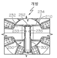
도 21은 도 19의 벤투리 장치의 벤투리 갭의 상세도이다.
도 22는 게이트 밸브의 제2 실시 예의 측면 투시도이다.
도 23은 벤투리 갭 내에 도 22의 게이트 밸브가 삽입되어 있는 도 19의 벤투리 장치의 벤투리 갭을 가로지르는 확대된 종단면도이다.1 is a longitudinal vertical cross-sectional view of an embodiment of a venturi device;
FIG. 2 is a longitudinal horizontal cross-sectional view of the venturi device of FIG. 1 ;
3 is a vertical cross-sectional perspective view taken along a plane parallel to the longitudinal central axis B at the junction of the suction port of a conventional venturi device having a circular cross-section in the motive section and the discharge section;
Fig. 4(a) is a vertical cross-sectional perspective view taken along a plane parallel to the longitudinal central axis B at the junction of the suction port of the venturi device of Fig. 2;
Fig. 4(b) shows the volume of the venturi gap of Fig. 4(a).
Figure 5 (a) is a vertical cross-sectional perspective view taken along a plane parallel to the longitudinal central axis (B) of the junction of the suction port in another embodiment of the venturi device.
Fig. 5(b) shows the volume of the venturi gap of Fig. 5(a).
6 is a plan view of the venturi device from the venturi device outlet, showing the offset between the motive outlet end and the exhaust inlet end;
7 is a model of the inner passage of the motive section of the venturi device;
8 is a graph comparing venturi device intake flow rates for a hyperbolic elliptical venturi device disclosed herein and a conical circular venturi device (prior art) at various selected manifold vacuum values.
9 is a graph comparing the vacuum of a hyperbolic elliptical venturi device disclosed herein versus a conical circular aspirator (prior art) as manifold vacuum is increased.
10 is a graph comparing canister emptying times with the hyperbolic elliptical venturi device disclosed herein for a conical circular aspirator (prior art) as manifold vacuum is increased.
11 is a perspective view of a lower housing section of a venturi device having a gate valve linearly movable into a venturi gap;
12 is a plan view of the suction port showing the gate valve in a closed position;
13 is a plan view of the suction port showing the gate valve in an open position;
14 is a side perspective view of the gate valve;
15 is a rear view of the gate valve.
16 is a plan view of the gate valve.
17 is a chart of data obtained from a performance comparison of a gated venturi device and a non-gated venturi device under the same conditions.
18 is an unassembled longitudinal cross-sectional view of one embodiment of a venturi device;
19 is a vertical longitudinal cross-sectional view of another embodiment of the venturi device.
Fig. 20 is a perspective view of only the body of the venturi device of Fig. 19;
FIG. 21 is a detailed view of a venturi gap of the venturi device of FIG. 19 ;
22 is a side perspective view of a second embodiment of the gate valve;
FIG. 23 is an enlarged longitudinal cross-sectional view across the venturi gap of the venturi device of FIG. 19 with the gate valve of FIG. 22 inserted within the venturi gap;
다음의 상세한 설명은 본 발명의 일반적인 원리를 설명할 것이며, 그 예들이 첨부 도면에 추가로 도시된다. 도면에서, 동일한 참조 번호는 동일하거나 기능적으로 유사한 요소를 나타낸다. The following detailed description will set forth the general principles of the invention, examples of which are further shown in the accompanying drawings. In the drawings, like reference numbers indicate identical or functionally similar elements.
본 명세서에서 사용되는 바와 같이, "유체"는 액체, 현탁액, 콜로이드, 가스 플라즈마, 또는 이것들의 조합을 포함한다. As used herein, “fluid” includes liquids, suspensions, colloids, gaseous plasmas, or combinations thereof.
또한, 도 1 및 도 2는 벤투리 장치(100)의 상이한 도면을 도시한다. 벤투리 장치(100)는 엔진에 예를 들어 차량 엔진에 사용되어 장치에 진공을 제공할 수 있다. 도 1에서, 벤투리 장치(100)는 진공 필요 장치(102)에 연결되고, 벤투리 장치(100)는, 벤투리 효과를 생성하도록 설계되고 대체로 벤투리 장치의 길이만큼 연장하는 통로(104)를 통한 공기 유동에 의해 상기 장치(102)를 위한 진공을 생성한다. 벤투리 장치(100)는, 통로(104)를 한정하고 엔진 또는 그것에 연결된 구성 요소에 연결할 수 있는 3개 이상의 포트를 갖는 몸체(106)를 포함한다. 상기 포트는 다음을 포함한다: (1) 모티브 포트(108), 이것은 예를 들어 스로틀(throttle)의 상류에 위치된, 도 11에서 박스(290)로 표시된 엔진 흡기 클리너로부터의 청정 공기 소스에 연결될 수 있음; (2) 흡입 포트(110), 이것은 선택적인 체크 밸브(111)를 통해 진공 필요 장치(102)에 연결될 수 있음; (3) 출구 포트(112), 이것은 예를 들어 엔진의 스로틀의 하류에서 도 11에서 박스(292)로 표시된 엔진 흡기 매니폴드에 연결됨; 및 선택적으로 (4) 바이패스 포트(114)를 포함할 수 있다. 포트(108, 110, 112, 114) 각각은 호스 또는 엔진의 다른 구성 요소에 각각의 포트를 연결하기 위한 커넥터 피처(feature)(117)를 그 외부 표면상에 포함할 수 있다. 1 and 2 also show different views of the
바람직하게는, 흡입 포트(110)로부터 적용 장치(102)로 유체가 유동하는 것을 방지하도록 체크 밸브(111)가 배치된다. 일 실시 예에서, 진공 필요 장치(102)는 차량 브레이크 부스트 장치, 포지티브 크랭크케이스 환기(PCV: positive crankcase ventialtion) 장치, 또는 연료 퍼지(purge) 장치. 다른 실시 예에서, 진공 필요 장치(102)는 유압 밸브이다. 바이패스 포트(114)는 진공 필요 장치(102에 연결될 수 있고, 선택적으로 그 사이의 유체 유동 경로(122)에 체크 밸브(120)를 포함할 수 있다. 체크 밸브(120)는 바이패스 포트(114)로부터 적용장치(102)로의 유체의 유동을 제어하도록 배치되는 것이 바람직하다. Preferably, a
이제, 도 2 및 도 3을 참조하면, 벤투리 장치(100)는 일반적으로 "T형" 벤투리 장치로서, 흡입 포트(110)에 의해 이등분된 종방향 중심축(B)을 따르는 내부 통로를 한정한다. 내부 통로(104)는 몸체(106)의 배출 섹션(146)의 제2 테이퍼링 부분(129)(본 명세서에서 배출 원추(cone)라고도 함)에 결합된 몸체(106)의 모티브 섹션(116)의 제1 테이퍼링 부분(128)(모티브 원추라고도 함)을 포함한다. 여기서, 제1 테이퍼링 부분(128) 및 제2 테이퍼링 부분(129)은 끝과 끝이 맞닿아 정렬되고, 모티브 출구 단부(132)와 배출 입구 단부(134)가 대면하고, 그 사이에 벤투리 갭(152)을 한정하며, 이것은 내부 통로(104)의 모티브 섹션(116) 및 배출 섹션(146) 양자와 유체 소통하는 흡입 포트(110)을 배치하는 유체 접합부를 한정한다. 여기서 사용된 벤투리 갭(152)은 모티브 출구 단부(132)와 배출 입구 단부(134) 사이의 직선 거리를 의미한다. Referring now to FIGS. 2 and 3 , the
벤투리 장치(100)와 같은 벤투리 장치가 차량 엔진에 사용될 때, 차량 제조사는 벤투리 장치를 엔진 또는 그 구성 요소에 연결하기 위해 이용할 수 있는 관류/호스 크기에 기초하여 모티브 포트(108)와 출구(112) 양자의 크기를 선택하는 것이 통상적이다. 또한, 차량 제조사는 벤투리 장치에서 사용하기 위해 이용 가능한 최대 모티브 유량을 선택하는 것이 통상적이며, 이는 이어서 모티브 출구 단부(132), 즉 모티브 출구(133)에 한정된 내부 개구의 면적을 결정할 것이다. 따라서, 특정 엔진에 대해 차량 제조사가 선택한 파라미터는 출구(112) 대비 모티브 출구(112)의 비율을 결정한다. 이러한 제한 내에서 작동하면서, 개시된 벤투리 장치(100)는 낮은(5kPa - 30 kPa) 소스/배출 압력에서 높은 흡입 유량을 생성하고자 하는 소망과 더 높은(30 kPa - 60 kPa) 소스/배출 압력에서 증가된 진공 깊이를 생성하고자 하는 소망 사이의 타협을 크게 감소시킨다. 이러한 타협의 감소는, 도 5 및 도 6에 도시된 바와 같이, 모티브 출구 단부(132)와 배출 입구 단부(134)에서 내부 통로(104)의 둘레를 증가시키기 위해 모티브 출구(133)와 (배출 입구 단부(134)에 의해 한정된) 배출 입구(135)에 대한 구성을 변경함으로써 달성된다. When a venturi device, such as the
도 5(a) 내지 도 5(b) 및 도 6에 도시된 바와 같이, 적어도 모티브 출구 단부(132)(모티브 출구(133))의 내부면 및 배출 입구 단부(134)(배출 입구(135))의 내부면은 타원형이지만, 대안으로 다각형 형태를 가질 수도 있다. 벤투리 갭(152)으로부터, 반대 방향으로, 모티브 출구 단부(132)로부터 및 배출 입구 단부(134)로부터 멀리 연장되는 내부 통로(104)의 내부는 동일한 일반적인 형상을 갖도록 구성될 수 있다. 도 7은 벤투리 장치의 모티브 섹션 내의 내부 통로의 형상의 일 실시 예를 도시하지만, 동일하게, 180° 회전시키면 배출 섹션 내의 내부 통로를 도시한다. 도 7의 내부 통로는 모티브 입구 단부(130)에서 면적(A1)을 가진 원형 개구로서 시작되고 A1보다 더 작은 면적(A2)을 가진 모티브 출구(133)의 타원형 개구까지 쌍곡선 또는 포물선 함수로서 점차 연속해서 전환한다. 모티브 입구 단부(130)의 원형 개구는, 모티브 출구 단부(132)에서의 유동 라인이 서로 평행한 이점을 제공하는 쌍곡선(170)에 의해 타원형 모티브 출구(133)에 연결된다. 모티브 입구 단부(130) 및 배출 출구 단부(136)는 또한 타원 형상 또는 어떤 다른 다각형 형상 개구를 그 전의 어떤 점에서 한정할 수 있으며, 상기 형상들로부터 원형 단면으로 전이하여 그 외부에 커넥터 피처(117)를 구비하는, 예를 들면 호스 연결부(119)와 유사한, 호스 연결부를 형성할 수도 있다. 5(a) to 5(b) and 6, at least the inner surface of the motive outlet end 132 (the motive outlet 133) and the outlet inlet end 134 (the outlet inlet 135) ) has an elliptical inner surface, but may alternatively have a polygonal shape. The interior of the
벤투리 장치(100)의 "T" 형상을 형성하기 위해, 흡입 포트(110)는 몸체의 종방향의 중심축(B)에 대해 대체로 수직인 종방향의 중심축(C)을 갖는다. 선택적인 바이패스 포트(114)는 마찬가지로 몸체의 종방향 중심축(B)에 대해 대체로 수직인 종방향 중심축(D)을 가질 수 있다. 도 1에 도시된 바와 같이, 바이패스 포트(114)는 배출 출구 단부(136)에 인접한 하류에서 제2 테이퍼링 부분(129)과 교차할 수 있다. 몸체(106)는 이후에, 즉 바이패스 포트의 이 교차부의 하류에서, 원통형의 균일한 내부 반경을 계속하다가 출구(112)에서 종료된다. 다른 실시 예(도시되지 않음)에서, 바이패스 포트(114) 및/또는 흡입 포트(110)는, 수직이 아니라, 축(B) 및/또는 서로에 대해 기울어질 수 있다. 도 2의 실시 예에서, 흡입 포트(110)와 바이패스 포트(114)는 서로 정렬되고 몸체의 종방향 중심축(B)에 대해 동일한 배향을 갖는다. 다른 실시 예에서(도시되지 않음), 흡입 포트(110)와 바이패스 포트(114)는 서로에게서 오프셋될 수 있으며, 연결하기 쉽도록 연결할 엔진 내부의 구성 요소와 관련하여 위치될 수 있다. To form the “T” shape of the
흡입 포트(110)는 흡입 입구(138)및 흡입 출구(배출 입구(135))을 포함하며, 제1 테이퍼링 섹션(128)과 마찬가지로, 원추처럼 그 길이를 따라 더 큰 치수의 흡입 입구(138)으로부터 더 작은 치수의 흡입 출구(135)까지 점차 연속해서 테어퍼지거나 대체로 원통형의 튜브일 수 있다. 바이패스 포트(114)는, 존재하는 경우, 그 길이를 따라 원추처럼, 특히 더 작은 치수의 단부(162)로부터 더 큰 치수의 단부(160)까지 점차 연속해서 테이퍼지거나, 대체로 원통인 튜브일 수 있다. 시스템 내에 벤투리 장치의 부착에 따라, 바이패스 포트(114)는 더 큰 치수의 단부(160)가 입구으로서 및 더 작은 치수의 단부(162)가 출구로서 또는 그 반대로 작동할 수 있다.
도 2 및 도 5에 도시된 바와 같이, 제2 테이퍼링 부분(129)에 나란히 놓인 제1 테이퍼링 부분(128)의 모티브 출구 단부(132)에서, 흡입 포트(110)는 벤투리 갭(152)과 유체 소통하는 공극(150)을 한정하는 확대된 영역을 포함하거나 또는 반대로 벤투리 갭(152)이 공극(150)의 일부로서 생각될 수도 있다. 내부 통로(104)와 흡입 포트(110)의 유체 접합부는 벤투리 갭(152)에 대해 대략 중심에 위치되며 공극(150)은 흡입 포트의 종방향 중심축(C)과 대체로 정렬되고 제1 테이퍼링 부분(128)에서 제2 테이퍼링 부분(129)으로 전환한다. 공극(150)은 길이가 흡입 포트의 내부 단면 치수와 유사하지만 그 바닥이 흡입 포트(110)로부터 떨어져 하방으로 돌출하는 아치형 돌출부인 평행육면체로서 형상화될 수 있다. 흡입 포트의 종방향 중심축(C)을 따라 몸체의 종방향 중심축(B)을 횡단하여 취해진 단면에서, 상기 공극은, 도 2, 도 4(a) 및 도 5(a)를 조합해서 볼 때 가장 잘 이해되는 바와 같이, 배출 입구 단부(134) 및 모티브 출구 단부(132)와 관련하여 대체로 U자 형상으로 보인다. 도 2 및 도 5(a)에 도시된 바와 같이, 흡입 포트는 모티브 출구 단부(132)의 측면들 및 배출 입구 단부(134)의 측면들 주위에서 하방으로 연장되며, 그 모든 측면들 사이에 공극(150)을 한정한다. 도 5(a)에 도시된 바와 같이, 모티브 출구 단부(132) 및 배출 입구 단부(134)의 외부 프로파일은 그 각각의 내부 형상과 대체로 일치한다. 2 and 5 , at the motive outlet end 132 of the
벤투리 장치(100)에서, 제1 테이퍼링 부분(128)을 통한 모티브 공기의 유동은 그 속도를 증가시키며, 이는 공극(150) 내에 낮은 정압(static pressure)을 발생시킨다. 이 낮은 정압은 흡입 포트(110)로부터 벤투리 갭(11) 내에 그리고 배출 섹션(146) 내에 공기를 끌어들여 배출 입구(흡입 출구)(135)로 통과시킨다.In the
벤투리 장치(100)는 다음의 기하학적 비율을 만족시키도록 작동될 수 있다:The

다음과 같은 성능비도 있다.There are also performance ratios as follows.

본 명세서에 개시된 쌍곡선의 유동 통로에 대해 비율(F)을 최대화하기 위해, 비율(A')은 3 내지 12이고, 비율(B')은 4보다 커야 하고, 비율(C')은 4보다 커야 한다. To maximize ratio F for the hyperbolic flow passages disclosed herein, ratio A' should be between 3 and 12, ratio B' should be greater than 4, and ratio C' should be greater than 4 do.
쌍곡선 유동 통로에 대해 비율(G)을 최대화하기 위해, 비율(A')은 3 내지 12이고, 비율(B')은 4보다 커야 하고, 비율(C')은 4보다 커야 한다. To maximize ratio G for a hyperbolic flow passage, ratio A' should be between 3 and 12, ratio B' should be greater than 4, and ratio C' should be greater than 4.
도 3의 종래 기술에서, 모티브 원추의 출구 단부 및 배출 원추의 입구 단부는 각각 원형 내부 단면 및 원형 외부 프로파일을 가지며, 그에 의해 원형 둘레를 갖는 원뿔대인 벤투리 갭을 한정한다. 이 도면으로부터 흡입 유동에 대한 제한들 중 하나가 실증된다 - 모티브 원추와 배출 원추에 대한 흡입 포트의 유체 접합부에서의 영역. In the prior art of FIG. 3 , the outlet end of the motive cone and the inlet end of the outlet cone respectively have a circular inner cross-section and a circular outer profile, thereby defining a venturi gap, which is a truncated cone with a circular perimeter. From this figure one of the limitations to the suction flow is demonstrated - the area at the fluid junction of the suction port to the motive cone and the discharge cone.
흡입 포트로부터 본 명세서에 개시된 벤투리 장치들의 벤투리 갭(152) 내로 공기의 유량을 증가시키기 위해, 제1 테이퍼링 부분(128) 및 제2 테이퍼링 부분(129)의 전체 내부 크기를 증가시키지 않고(바람직하게는 질량 유량을 증가시키지 않고) 출구 단부(132) 및 입구 단부(134)의 둘레(perimeter)를 증가시킴으로써 벤투리 갭의 영역이 증가된다. 특히, 모티브 출구 단부(132) 및 배출 입구 단부(134)는 전술한 바와 같이 원형으로부터 비 원형으로 변경된다. 원형이 아니고 각각 둘레와 단면적을 가진 가능한 형상은 무수히 많이 있다. 이것들은 다각형, 또는 서로 연결된 직선 세그먼트들, 원형 아닌 곡선, 및 심지어 프랙탈(fractal) 곡선을 포함한다. 비용을 최소화하기 위해, 곡선은 더 간단하고 제조 및 검사가 쉬으며, 바람직한 둘레 길이를 가진다. To increase the flow rate of air from the suction port into the
도 4(a), 도 4(b), 도 5(a), 및 도 5(b)는, 흡입 포트(110)가 모티브 출구 단부(132) 및 배출 입구 단부(134)와 만나는 개선된 유체 접합부를 갖는 실시 예를 도시한다. 흡입 포트(110)로부터 벤투리 갭(152)까지의 유로의 최소 영역은 모티브 출구 단부(132)와 배출 입구 단부(134) 사이에 형성된 원뿔대(frustum)이다(도 4(b) 및 도 5(b) 참조). 또한, 도 4(a) 및 도 4(b)에서, 모티브 원추(128)의 출구 단부(132) 및 배출 원추(129)의 입구 단부(134)는 각각 내측 및 외측 타원형 둘레를 가지며, 그에 의해 타원형 둘레를 갖는 원뿔대인 벤투리 갭(152)을 한정한다. 또한, 도 5(a) 및 도 5(b)에서, 모티브 원추(128)의 출구 단부(132) 및 배출 원추(129)의 입구 단부(134)는 각각 내측 및 외측의 대략 직사각형 형상의 둘레(모서리가 둥근)를 가지며, 그에 의해 대체로 직사각형 형상의 둘레를 가진 벤투리 갭(152)을 한정한다. 도면의 실시 예들이 출구 단부(132) 및 입구 단부(134)에 대해 동일한 둘레를 가지지만, 즉 둘 다 타원형이거나 둘 다 대체로 직사각형이지만, 출구 단부(132) 및 입구 단부(134)는 상이한 형상의 둘레를 가질 수도 있다. 즉, 하나는 타원형인 반면 다른 하나는 대체로 직사각형일 수 있다. 또한, 모티브 출구 단부(132) 및 배출 입구 단부(134)는 흡입 포트(110)로부터 배출 입구 단부(134) 내로의 유체의 유동 지향성을 향상시키기 위해 둥근 모따기(rounded chamfer)로 종료될 수 있다. 4(a), 4(b), 5(a), and 5(b) show the improved fluid where the
또한, 도 6에서 가장 명확하게 도시되고, 도 4(b) 및 도 5(b)의 원뿔대에서도 볼 수 있는 바와 같이, 각 실시 예에 대한 모티브 원추(128)의 출구 단부(132)는 배출 원추(129)의 입구 단부(134)보다 치수가 작다. 치수의 이러한 차이는 오프셋(140)으로 식별된다. 도 4(b)에서, 예를 들면, 상기 오프셋은, 모티브 출구 단부(132)의 주축(Y)의 길이가 배출 입구 단부(134)의 주축(Y')의 길이보다 작고, 또한 배출 입구 단부(134)의 부축(X')의 길이보다 짧은 모티브 출구 단부(132)의 부축(X)의 길이가 작은 것으로 보여진다. Also, the
타원형 또는 다각형 형상의 임의의 실시 예에서, 상기 수렴형 모티브 섹션의 모티브 출구 단부의 타원형 또는 다각형 형상의 내부 단면은 약 2 내지 약 4의 부축 대비 주축의 비율을 가지며, 발산형 배출 섹션의 입구 단부의 타원형 또는 다각형 형상의 내부 단면은, 상기 수렴형 모티브 섹션의 출구 단부의 타원형 또는 다각형 형상의 내부 단면에 대해, 피크 모티브 유량 대비 배출 입구 영역과 모티브 출구 영역의 차이의 비율에 상수 k 1 을 곱한 0.28보다 큰 단위 없는 비율만큼 오프셋 된다.In any embodiment of the elliptical or polygonal shape, the elliptical or polygonal inner cross-section of the motive outlet end of the converging motive section has a minor-to-major axis ratio of about 2 to about 4, wherein the inlet end of the diverging motive section The elliptical or polygonal inner cross-section is greater than 0.28 multiplied by the constant k 1 by the ratio of the difference between the discharge inlet area and the motive outlet area to the peak motive flow rate for the elliptical or polygonal inner cross-section of the outlet end of the converging motive section. It is offset by a large unitless ratio.
오프셋 비율=(배출 입구 면적-모티브 출구 면적)/피크 모티브 유량*k1 (V)Offset ratio = (discharge inlet area - motive outlet area)/peak motive flow*k 1 (V)
여기서 k 1 은: where k 1 is:
k 1 = c(모티브 출구 단부에서)*D유체(모티브 출구 단부에서) (Ⅵ) k 1 = c (at motive outlet end)*D fluid (at motive outlet end) (VI)
여기서 c는 음속이고, D유체는 유체(통상적으로 공기)의 밀도이다. where c is the speed of sound and D fluid is the density of the fluid (usually air).
타원형 또는 다각형 형상의 임의의 실시 예에서, 모티브 출구 단부와 배출 입구 단부 사이의 벤투리 갭은 벤트리 갭의 면적을 모티브 유량으로 나누고 k 2 를 곱한 것으로 정의된 단위가 없는 갭 비율을 가진다. In any embodiment of the elliptical or polygonal shape, the venturi gap between the motive outlet end and the exhaust inlet end has a unitless gap ratio defined as the area of the venturi gap divided by the motive flow rate multiplied by k 2 .
갭 비율 = 벤투리 갭의 면적/모티브 유량*k 2 (Ⅶ)Gap Ratio = Area of Venturi Gap/Motive Flow* k 2 (VII)
여기서 k 2 는: where k 2 is:
k 2 = c(모티브 출구 단부에서)*D유체(모티브 출구 단부에서) (Ⅷ) k 2 = c(at motive outlet end)*D fluid (at motive outlet end) (VIII)
여기서, c 및 D유체는 위에 정의된 바와 같다. 또한, 갭 비율은 4.7보다 크다.Here, c and D fluids are as defined above. Also, the gap ratio is greater than 4.7.
일 실시 예에서, 모티브 출구 단부(132)의 타원형 또는 다각형 내부 단면은 0 내지 1의 이심률(eccentricity)을 가진다. 다른 실시 예에서, 출구 단부의 타원형 또는 다각형 내부 단면은 약 0.4 내지 약 0.97의 이심률을 갖는다. In one embodiment, the elliptical or polygonal inner cross-section of the
다시 도 4(a) 및 도 4(b)를 참조하면, 출구 단부(132) 및 입구 단부(134)는 프로파일이 타원형이어서 주축(Y) 및 부축(X)을 갖는다. 타원 방정식은 다음과 같이 정의할 수 있다: X2/B2 + Y2/A2 = 12. 여기서 A는 주축(Y)을 따라 원점에서 타원까지의 거리이고 B는 부축(X)을 따라 원점에서 타원까지의 거리이다. 타원의 면적은 다음과 같다:Referring again to FIGS. 4( a ) and 4 ( b ), the
타원의 면적 = π x A x B (I)Area of an ellipse = π x A x B (I)
타원의 둘레는 간단하고 정확한 방정식으로 주어지지 않는다. 대신 시리즈 방정식이 허용 가능한 근사치를 제공한다:The circumference of an ellipse is not given by a simple and precise equation. Instead, the series equation gives an acceptable approximation:
타원의 둘레 = π x (A+B) x (1 + h2/4 + h4/64 + h6/256 ...) (Ⅱ)The circumference of the ellipse = π x (A+B) x (1 + h 2 /4 + h 4 /64 + h 6 /256 ...) (Ⅱ)
여기서 h는: where h is:
변수 h = (A-B)/(A+B) (Ⅲ)Variable h = (A-B)/(A+B) (III)
우리는 두 축의 길이를 관련시키는 용어인 이심률이라는 용어를 더 정의할 수 있다. 그것은 다음과 같이 정의된다: We can further define the term eccentricity, a term relating the lengths of two axes. It is defined as:
변수 e = (A2 - B2)1/2/A (IV) Variable e = (A 2 - B 2 ) 1/2 /A (IV)
벤투리 장치를 위한 선택된 모티브 유동이 제공되는 경우, 디자인은 종래의 원형 벤투리 장치의 반경이 1 mm이고, 면적이 3.14 mm2이고 둘레가 6.28 mm인 계산에 대해 동등하게 선택될 수 있다. 면적 대 둘레의 비율은 모티브 출구 단부와 배출 입구 단부의 원형 내부 단면의 경우 수학적으로 2와 동일하다. Given the selected motive flow for the venturi device, the design can be equally chosen for calculations where a conventional circular venturi device has a radius of 1 mm, an area of 3.14 mm 2 and a perimeter of 6.28 mm. The ratio of area to perimeter is mathematically equal to two for the circular inner cross-sections of the motive outlet end and the outlet inlet end.
주어진 이심률을 가진 타원에 대해서 우리는 면적, 둘레, 및 개시된 실시 예에서 단면적 대 둘레의 비율을 계산할 수 있다. 면적을 반경 1mm의 원의 면적과 같게 제한하면, 계산된 결과는 표 3과 같다. For an ellipse with a given eccentricity we can calculate the area, perimeter, and ratio of cross-sectional area to perimeter in the disclosed embodiment. If the area is limited to be equal to the area of a circle with a radius of 1 mm, the calculated results are shown in Table 3.

따라서, 이심률을 변경함으로써, 단면적을 고정한 상태에서 둘레가 증가될 수 있다. 이러한 둘레의 증가는 흡입 포트, 모티브 원추 및 배출 원추 사이의 접합부에서 교차 면적을 증가시켜서, 흡입 포트 유량을 증가시키는 이점을 제공한다. Therefore, by changing the eccentricity, the circumference can be increased while the cross-sectional area is fixed. This increase in circumference increases the crossover area at the junction between the suction port, motive cone and discharge cone, providing the advantage of increasing suction port flow rate.
이제, 도 5(a) 및 도 5(b)를 참조하면, 모티브 출구 단부(132) 및 배출 입구 단부(134)는 프로파일이 대체로 직사각형이며, 그에 의해 길이 및 폭과 그에 따라 2 개의 축, 즉 주축(U) 및 부축(V)을 갖는다. 도시된 바와 같이, 출구 단부(132) 및 입구 단부(134)에 대한 벤투리 장치의 대체로 직사각형인 프로파일은 직사각형 부분의 폭에 대응하는 반원형 단부를 포함한다. Referring now to Figures 5(a) and 5(b), the
출구 단부(132) 및 입구 단부(134)의 프로파일의 배향은 그에 제한되는 것으로 해석되어서는 안 된다. 이 직사각형의 면적은 반원들 사이의 직선 구간의 면적과 두 개의 단부 반원들의 면적의 합과 같다. 직사각형의 둘레 길이는 두 변의 길이에 반원 단부들의 길이를 더한 길이와 같다. 우리는 표 4와 같이 계산할 수 있다.The orientation of the profiles of the
원형 단면을 같은 면적을 가진 대체로 직사각형 단면으로 변경하면 전술한 타원 프로파일과 유사하게 면적 대 둘레의 비율이 증가하는 결과가 얻어진다. 이러한 둘레의 증가는 벤투리 갭과 흡입 포트 사이의 교차 면적을 증가시켜서, 흡입 포트 유동의 증가를 가져오는 이점을 제공한다. Changing the circular cross-section to a generally rectangular cross-section with the same area results in an increased area-to-perimeter ratio, similar to the elliptical profile described above. This increase in perimeter provides the advantage of increasing the crossover area between the venturi gap and the suction port, resulting in an increase in suction port flow.
흡입 유동을 증가시키는 다른 방법은 모티브 원추(128)의 출구 단부(132)와 배출 원추(129)의 입구 단부(134) 사이의 거리를 연장하는 것이다. 모티브 유동은 벤투리 갭을 통해 흐르면서 흡입 공기와 섞인다. 이 혼합된 유동은 벤투리의 배출 단부를 향해 정압을 증가시키는 효과를 갖는다. 이 거리를 연장하면 반환을 감소시키고, 모티브 유동이 벤투리에서 크게 제약받지 않으므로 난류 및 유동 교란의 위험을 초래하며 이는 속도를 감소시키고 정압을 증가시킬 수 있다. 따라서, 위에서 설명된 둘레의 증가는 거리를 연장하는 것보다 선호되지만, 감소하는 반환을 피하기 위해 두 방법을 결합할 수 있다. Another way to increase the suction flow is to extend the distance between the

본 명세서에 개시된 벤투리 장치는 단일체(monolithic body)로서 성형될 수 있다. 일 실시 예에서, 벤투리 장치는 사출 성형에 의해 형성된다. The venturi devices disclosed herein may be molded as a monolithic body. In one embodiment, the venturi device is formed by injection molding.
일 실시 예에서, 벤투리의 갭(152)은 (모티브 질량 유량)n에 비례하는 직선 거리이고, n은 0.25 내지 0.8이며, 상기 모티브 출구와 배출 입구 사이의 오프셋 역시 (모티브 질량 유량)n이 비례하고, n은 0.25 내지 0.8이며, 상기 출구 단부의 타원형 또는 다각형 형상의 내부 단면은 0 내지 1, 더욱 바람직하게는 약 0.4 내지 약 0.97의 이심률을 갖는다. 벤투리 장치가 더 높은 진공 양을 요구하는 장치를 갖는 시스템에 포함될 때, 벤투리 갭에 대한 n 및 오프셋에 대한 n은 모두 0.4 내지 0.6일 수 있다. 일 실시 예에서, 벤투리 갭에 대한 n 및 오프셋에 대한 n은 모두 0.5이며 이심률은 약 0.4 내지 0.97이다. 다른 실시 예에서, 3으로 나눈 타원의 긴 지름이 타원의 짧은 지름과 동일한 경우, 갭 비율은 타원의 짧은 지름과 동일한 값으로 설정되며, 여기서 각 값의 정확도는 +/-10%이다. In one embodiment, the
동작 시, 예를 들어 벤투리 장치가 엔진에 연결될 때, 엔진 공기, 즉, 필터링 된 공기가 모티브 포트에서 벤투리 장치에 들어가도록 연결될 수 있다. 배출 포트에서 벤투리 장치를 나가는 공기는 압력이 모티브 포트의 압력보다 낮은 지점에서 엔진 공기에 연결될 수 있다. 모티브에서 배출 포트까지의 공기의 움직임은 모티브 원추의 아래로 공기를 끌어당기며, 상기 모티브 원추는 직선 원추 또는 위의 설명과 같이 쌍곡선 프로파일이 될 수 있다. 면적의 감소는 공기의 속도를 증가시킨다. 이것은 밀폐된 공간이므로 유체 역학의 법칙에 따라 유체 속도가 증가할 때 정압이 감소해야 한다. 모티브 원추의 최소 단면적은 벤투리 갭과 접한다. 공기가 배출 포트로 계속 이동함에 따라 직선 원추 또는 쌍곡선 프로파일인 배출 원추를 통과하여 이동한다. 선택적으로, 배출 영역은 배출 포트와 결합할 때까지 직직선 또는 쌍곡선 프로파일 원추로서 계속되거나, 단순한 원통형 또는 테이퍼진 통로로 전환될 수 있다. 배출 원추의 최소 단면적 단부는 모티브 원추의 최소 단면적 단부보다 크다. 더 큰 면적은 흡입 포트로부터의 공기의 유동을 위한 면적을 제공하기 위한 것이다. 배출 원추 아래로의 이 면적의 변화는 공기의 속도를 다시 낮추어, 그 정압의 후속적인 증가를 야기한다. In operation, for example, when the venturi device is coupled to the engine, engine air, ie, filtered air, may be coupled to enter the venturi device at the motive port. Air exiting the venturi unit at the exhaust port may be coupled to engine air at a point where the pressure is less than the pressure at the motive port. The movement of air from the motive to the exhaust port draws air down the motive cone, which can be a straight cone or a hyperbolic profile as described above. A decrease in area increases the velocity of the air. Since this is an enclosed space, according to the laws of fluid mechanics, the static pressure must decrease as the fluid velocity increases. The minimum cross-sectional area of the motive cone is tangent to the venturi gap. As the air continues to travel to the exhaust port, it travels through the exhaust cone, which is either a straight cone or a hyperbolic profile. Optionally, the evacuation region may continue as a straight or hyperbolic profile cone until it engages an evacuation port, or may be converted to a simple cylindrical or tapered passageway. The minimum cross-sectional area end of the exit cone is greater than the minimum cross-sectional area end of the motive cone. The larger area is to provide an area for the flow of air from the intake port. A change in this area down the exhaust cone lowers the velocity of the air again, causing a subsequent increase in its static pressure.
벤투리 갭은 흡입 포트에 연결되며, 흡입 포트는 모티브 원추와 배출 원추 사이에서 고속으로 통과하는 공기에 존재하는 동일한 낮은 정압에 흡입 포트/통로의 공기를 노출한다. 여기서 생성된 압력은 배출 포트에서의 압력보다 낮을 수 있는데, 이것은 모티브 포트에서의 압력보다 낮은 것으로 이미 알려져 있다. 이러한 낮은 압력은, 통상의 기술자에게 공지된 바와 같이, 예를 들어 차량 브레이크 부스트 캐니스터를 비우기 위한 것과 같이 차량 상의 다양한 용도에 사용될 수 있다. 일부 상황에서는, 주로 가솔린 엔진이 가볍게 적재될 때, 배출 포트에서의 압력은 적용 장치에서의 압력을 신속하게 낮추기에 충분히 낮다. 배출 원추 또는 통로와 바이패스 통로 사이의 연결부 영역이 흡입 통로와 벤투리 갭 사이의 연결부에 비해 상당히 크기 때문에, 이러한 선택적인 연결은 초기에 적용 장치의 배기를 도울 수 있다. The venturi gap is connected to the intake port, which exposes the air in the intake port/passage to the same low static pressure present in the air passing at high speed between the motive cone and the exhaust cone. The pressure created here may be lower than the pressure at the outlet port, which is already known to be lower than the pressure at the motive port. This low pressure can be used in a variety of applications on the vehicle, such as, for example, to empty the vehicle brake boost canister, as is known to those skilled in the art. In some situations, mainly when a gasoline engine is lightly loaded, the pressure at the exhaust port is low enough to quickly lower the pressure in the application device. Since the area of the connection between the exhaust cone or passageway and the bypass passageway is significantly larger than the connection area between the intake passageway and the venturi gap, this optional connection may initially assist evacuation of the application device.
비교 연구를 위해, 도 7에 도시된 것과 같은, 벤투리 갭에서 타원 모티브 출구 및 타원 배출 입구와 모티브 및 배출 섹션에서 쌍곡면 내부 프로파일을 가진 3 gps 벤투리 장치(이하 "쌍곡면 타원 벤투리 장치"로 지칭)가 브레이크 부스터 캐니스터 진공의 증가와 함께 10 kPa의 매니폴드 진공, 15 kPa의 매니폴드 진공, 및 20 kPa의 매니폴드 진공 조건에서 작동되었으며 동일한 조건에서 3gps의 원추형 원형 벤투리 장치와 비교되었다. 원추형 원형 벤투리 장치는 원형 모티브 출구 및 원형 배출 입구와 모티브 및 배출 섹션에서 원추형 내부 프로파일을 갖는 장치이다. 도 8에 제시된 데이터에 의해 입증된 바와 같이, 쌍곡선 타원 벤투리 장치는 원추형 원형 벤투리 장치의 결과를 초과하는 타원형 개구부들과 쌍곡면 내부 프로파일의 시너지 효과를 제공했다. 10 kPa, 15 kPa 및 20 kPa의 매니폴드 압력에서, 쌍곡면 타원 벤투리 장치는 12 kPa에서 약 67 kPa까지 증가하는 브레이크 부스트 캐니스터 진공 범위에서 더 높은 흡입 유량을 제공했다. 흥미롭게도, 15 kPa의 매니폴드 압력에서 쌍곡면 타원 벤투리 장치는 20 kPa의 매니폴드 압력에서 원추형 원형 벤투리 장치와 거의 유사하게 수행되어, 예상치 못한 우수한 성능을 입증했다. For comparative studies, a 3 gps venturi device with an elliptical motive outlet and an elliptical exhaust inlet in the venturi gap and a hyperbolic inner profile in the motive and exhaust section, such as that shown in FIG. ") was operated at manifold vacuum of 10 kPa, manifold vacuum of 15 kPa, and manifold vacuum of 20 kPa with increasing brake booster canister vacuum compared to a conical circular venturi unit of 3 gps at the same conditions. became A conical circular venturi device is a device having a circular motive outlet and a circular discharge inlet and a conical inner profile in the motive and discharge section. As evidenced by the data presented in FIG. 8 , the hyperbolic elliptical venturi device provided a synergistic effect of the hyperbolic inner profile with elliptical openings exceeding the results of the conical circular venturi device. At manifold pressures of 10 kPa, 15 kPa and 20 kPa, the hyperbolic elliptical venturi device provided higher intake flow rates in the brake boost canister vacuum range increasing from 12 kPa to about 67 kPa. Interestingly, the hyperbolic elliptical venturi device at a manifold pressure of 15 kPa performed almost similarly to the conical circular venturi device at a manifold pressure of 20 kPa, demonstrating unexpectedly superior performance.
이제, 도 9 및 도 10을 참조하면, 도 8에서 비교된 동일한 벤투리 장치들이 생성할 수 있는 최종 진공 및 벤투리 장치가 캐니스터를 비워서 진공을 생성하는 데 필요한 시간에 대해서 비교되었다. 시험을 위해, 출구(112)는 엔진의 흡기 매니폴드와 유체 소통하고, 흡입 포트는 차량 브레이크 부스터 캐니스터와 유체 소통하며, 모티브 입구는 깨끗한 공기의 소스에 연결되었다. 도 9의 그래프에 도시된 바와 같이, 본 명세서에 개시된 쌍곡면 타원 벤투리 장치는 동일한 작동 조건하에서, 즉 10, 15 및 20 kPa의 매니폴드 진공에서 원추형 원형 벤투리 장치에 비해 더 깊은 진공을 제공하며, 쌍곡면 타원 벤투리 장치는 적어도 5 kPa만큼 더 큰 최종 진공을 가졌다. 또한, 도 10에 도시된 바와 같이, 쌍곡면 타원 벤투리 장치는 원추형 원형 벤투리 장치에 비해 브레이크 부스트 캐니스터를 배기하는데 우수했다. 10 kPa의 매니폴드 진공 압력에서, 쌍곡면 타원 벤투리 장치는 캐니스터를 비울 때 4.5초보다 빨리 끝났다. 15 kPa 및 20 kPa의 매니폴드 진공에서, 쌍곡면 타원 벤투리 장치는 약 2초 더 빨랐다. 더 낮은 매니폴드 진공에서의 더 빠른 배기 시간은 더 빠른 반응 시간과 개선된 성능을 제공한다. 그러나 이들 그래프에서 볼 수 있듯이, 쌍곡면 타원형 프로파일을 갖는 벤투리 장치는 더 빠른 배기 시간을 가질 뿐만 아니라, 10, 15 및 20 kPa의 매니폴드 진공에서 더 깊은 진공을 제공한다. 이러한 이중 이점은, 벤투리 갭을 한정하는 모티브 출구 및 배출 입구의 형상을 변경하고 쌍곡선 함수에 따라 변화하거나 테이퍼지는 내부 통로를 사용한 뜻밖의 결과이다. Referring now to FIGS. 9 and 10 , the final vacuum that the same venturi devices compared in FIG. 8 could produce and the time required for the venturi device to empty the canister to create a vacuum were compared. For testing, the
이제, 도 11 내지 도 13을 참조하면, 본 명세서에서 설명된 진공을 발생시키기 위한 벤투리 장치의 다양한 실시 예는 모티브 섹션(216)으로부터 배출 섹션(246)으로의 유체의 통과를 제어하기 위해 벤투리 갭(252) 내에 밸브 게이트(300)를 포함할 수 있다. 벤투리 장치(200)는, 수렴형 모티브 섹션(216)의 출구 단부(232)와 발산형 배출 섹션(246)의 입구 단부(234) 사이에 벤투리 갭을 한정하는 도 11의 하부 몸체(206)와 같은 몸체, 벤투리 갭(252)과 유체 소통하는 흡입 포트(210), 벤투리 갭(252)을 개폐하기 위해 직선 이동할 수 있는 게이트 밸브(300), 및 개방 위치(O)(도 13 참조)와 폐쇄 위치(C)(도 12 참조) 사이에서 게이트 밸브(300)를 작동 가능하게 움직이기 위해 게이트 밸브(300)에 연결된 액추에이터(310)를 가진다. 수렴형 모티브 섹션(216)은 원형 모티브 입구(208)를 한정하고 타원형 또는 다각형 모티브 출구(233)를 한정하며, 발산형 배출 섹션(246)은 타원형 또는 다각형 배출 입구(235)를 한정한다.Referring now to FIGS. 11-13 , various embodiments of a venturi apparatus for generating a vacuum described herein are provided with a vent to control the passage of fluid from the
포트(208, 212) 각각은 각 포트를 호스 또는 엔진 내 다른 구성 요소에 연결하기 위한 커넥터 피처(217)를 그 외부 표면상에 포함할 수 있다. 다른 포트(210, 282)는 유체 기밀 시일로 다른 구성요소들에 밀봉 연결(예를 들어 상부 하우징(204)을 흡입 포트(210)에 및 액추에이터(310)를 포트(282)에 연결)하기 위한 립(lip) 또는 다른 유형의 커넥터를 각각 포함할 수 있다. 도 18을 참조하면, 상부 하우징(204) 및 하부 하우징(206)은, 흡입 포트(210)의 접합부에서, 밀봉 디스크(213)가 내부에 안착된 체크 밸브(211)를 형성할 수 있다. 하부 몸체(206)의 흡입 포트(210)로부터 상방으로 연장하는 핑거(218)는 체크 밸브(211)의 개방 위치에 대해 밀봉 디스크(213)를 위한 자리를 형성한다. 상부 하우징(204)은 체크 밸브(211)의 챔버(224)와 하부 몸체(206)의 흡입 챔버(250) 입구(222)에 이르는, 복수의 개구를 포함하는 통로(220)를 한정한다. Each of the
상기 하부 몸체(206)는 수렴형 모티브 섹션(216)의 종방향 중심축(A)을 횡단하는 게이트 포켓(280)을 한정한다. 게이트 포켓(280)은 액추에이터(310)에 연결 가능한 커넥터(281)에 의해 하부 몸체(206)의 외부에서 종료된다. 게이트 포켓(280)은, 종방향 중심축(A)에 평행한 단면에서 볼 때, 대향 단부에서보다 흡입 포트(210)에 더 근접한 단부에서 더 넓은 사다리꼴 형상을 갖는다. The
도 11-16을 참조하면, 게이트 밸브(300)는 게이트 포켓(280) 내에 슬라이딩 안착된다. 게이트 밸브(300)는, 종방향 단면에서 보았을 때(도 16 참조) 대체로 U자 형상의 연속적인 조각으로 접혀지거나 구부러지거나 몰딩된 비-부식 금속 또는 플라스틱의 얇은 조각으로 만들어지며, 도 12의 폐쇄된 상태(C)일 때 모티브 출구(233) 및 배출 입구(235)를 폐쇄하도록 형성된다. 연속적인 대향 측면들(302, 304)은 항상 흡입 포트(210)와 유체 소통하는 공극(308)을 사이에 한정하도록 일정 거리 이격되어 있다. 게이트 밸브(300)의 제1 측면(302)은 수렴형 모티브 섹션(216)의 출구 단부(233)와 밀봉 맞물림 상태에 있고, 제2 측면(304)은 발산형 섹션(246)의 입구 단부(235)와 밀봉 맞물림 상태에 있다. 게이트 밸브(300)의 대향 측면들(302, 304) 각각은 밀봉 맞물림을 형성하도록 일반적으로 서로 편향된 판 스프링으로서 작용한다. 특히, 제거된 자유 상태에서, 크기, 즉 상부 또는 하부(314) 또는 상부(312)에서 측정된 표면(302)과 표면(304) 사이의 거리는, 상기 표면들이 모티브 섹션의 출구 단부(233) 및 배출 섹션의 입구 단부(235)를 접촉하도록 결정된다. 이것은 본 발명에 2가지 이점을 제공한다. 첫째, 간섭에 의해 생성된 항력(drag)이, 폐쇄 위치(C) 또는 개방 위치(O)에 있을 때 밸브(300)가 고정된 상태로 위치가 유지되는 것을 보장할 것이다. 이것은 밸브(300)가 덜컹거리는 경우 발생할 수 있는 마모를 제거할 것이다. 둘째, 동작 동안, 모티브 포트와 배출 포트 사이의 압력차가 게이트를 배출 통로를 향하여 동일한 방향으로 항상 편향시킨다. 밸브(300)가 배출 통로를 향해 편향되도록 보장함으로써, 모티브 포트와 배출 포트 사이의 잠재적 누출이 최소화된다. 11-16 , the
도 15에 도시된 바와 같이, 게이트 밸브(300)는 대향 단부(314)보다 흡입 포트(210)에 더 근접한 단부(312)에서 더 넓은 사다리꼴 형상의 배면(306)을 갖는다. As shown in FIG. 15 , the
일 실시 예에서, 액추에이터(310)는 게이트 벨브를 개방 위치(O)와 폐쇄 위치(C) 사이에서 작동 가능하게 이동시키도록 게이트 밸브에 연결된 공압 액추에이터이다. 공압 액추에이터는 자체제어 시스템 구성을 위해 벤투리 장치에 의해 생성된 진공을 사용하여 작동될 수 있다. 공압식 액추에이터의 예는 계류중인 미국 특허 출원 일련번호 14/154,268 및 일련번호 14/277,815에 기재되어 있다. 다른 실시 예에서, 액추에이터(310)는 게이트 밸브를 개방 위치와 폐쇄 위치 사이에서 작동 가능하게 이동시키도록 게이트 밸브(300)에 연결된 전자기 액추에이터이다(예를 들어 솔레노이드). 예시적인 솔레노이드는 계류중인 미국 특허 출원 일련번호 14/473,151에 기재되어 있다. In one embodiment,
도 11에 도시된 바와 같이, 게이트 밸브(300)는, 모티브 출구(233)의 부축에 평행한 평면에 있는 최단 스트로크 거리에서 직선 이동을 위해 타원형 또는 다각형의 모티브 출구(233)와 관련하여 위치된다. 예를 들어, 4mm 반경을 가진 원형 배출 입구는 4mm의 스트로크 거리를 갖지만, 2.3mm의 부축을 가진 4mm 원과 동일한 면적을 갖는 타원형 배출 입구는 스트로크 거리가 2.3mm 밖에 되지 않는다. 이것은 원형 배출 입구에서의 거리의 절반 정도이다. 11 , the
도 11 및 도 18에 도시된 바와 같이, 게이트 밸브(300)는 하부 몸체(206)의 상부 또는 하부보다는 하부 몸체(206)의 측면으로부터 흡입 챔버(250)로 진입하도록 위치된다. 이 구조는 게이트 밸브(300)를 타원형 배출 입구의 부축과 정렬시키고 최단 스트로크 거리를 제공하여, 개방 위치(O)로부터 폐쇄 위치(C)로 또는 그 반대로의 이동하는 시간과 작동 장치(전자석 또는 공압식)의 크기를 감소시킨다.11 and 18 , the
또한, 도 17을 참조하면, 하부 몸체(206)의 구조에 게이트 밸브(300)의 도입으로 예상치 못한 결과가 발견되었다. 게이트 밸브가 존재할 때, 게이트 밸브가 없는 등가의 벤투리 장치(즉, 비 게이트형 벤투리 장치)에 비해, 유량(초당 그램 단위)은 10 kPa 소스 진공일 때 약 5.5% 증가하고 20 kPa 소스 진공일 때 약 2% 증가하는 만큼 더 높다. 또한, 10 kPa 소스 진공의 경우, 흡입 진공이 약 3% 증가했다. 본 발명자들은 게이트의 도입이 성능을 약간 감소시킬 것으로 예상했지만, 도 7에 도시된 바와 같이, 10 kPa 및 20 kPa 소스 진공 하에서 적어도 일 측면에서 성능을 실제로 향상시켰다. Also, referring to FIG. 17 , an unexpected result was found with the introduction of the
이제, 도 19 및 도 20을 참조하면, 벤투리 장치의 다른 실시 예('400'으로 표시함)가 개시되어 있다. 벤투리 장치(400)는 진공 필요 장치(102)에 연결되고, 통로(404)를 한정하고 다양한 포트들을 가지는 몸체(406)를 포함한다. 상기 다양한 포트들에는 모티브 포트(408), 한 쌍의 흡입 포트(410a, 410b), 흡인기 출구(412), 액밀(fluid tight)/기밀 시일로, 예컨대 소닉(sonic) 용접, 열, 또는 사이에 이러한 시일을 형성하기 위한 다른 종래의 방법에 의해 몸체(406)에 연결된 흡입 하우징(407), 및 선택적으로 이중 바이패스 포트(414(a), 414(b))를 포함한다. 흡입 하우징(407) 및 몸체(406)는 함께 체크 밸브(420 및/또는 421)를 형성하며, 이것은 존재한다면 각각 밀봉 부재(411, 411')를 포함한다. 또한, 벤투리 장치(400)는 챔버(456)의 단부 및 챔버(466)의 단부를 각각 한정하는 제1 캡(409a) 및 제2 캡(409b)을 포함한다. 제1 및 제2 캡(409a, 409b)은 액밀/기밀 시일로 예를 들어 소닉 용접, 열, 또는 이러한 시일을 형성하기 위한 다른 종래의 방법에 의해 그것에 연결된다. 캡(409a, 409b) 대신에, 몸체(406)는 이것들이 일체형 폐쇄 챔버가 되도록 성형될 수 있다. Now, referring to FIGS. 19 and 20 , another embodiment of a venturi device (denoted by '400') is disclosed. The
몸체(406)는 흡입 포트(410a, 410b)에 의해 이등분된 종방향 중심축(404)을 따라 통로(404)를 한정한다. 내부 통로(404)는 제1 테이퍼링 부분(428) 및 제2 테이퍼링 부분(429)를 포함하고 이것들은 끝과 끝이 접하여 정렬되며 모티브 출구 단부(432)가 배출 입구 단부(434)와 마주하고 그 사이에 벤투리 갭(452)을 한정한다. 아래에 설명되지 않은 벤투리 장치(400)의 구성 요소는 다른 실시 예에 관해서 전술한 것과 유사한 것으로 이해된다.
도 19 및 도 20의 몸체(406)는 제1 흡입 포트(410a)와 제2 흡입 포트(410b)를 거리(D400)만큼 서로 이격시키는 챔버(456)을 추가로 한정한다. 챔버(456)는 복수의 핑거(finger)(442)를 포함하며 이것들은 몸체(406)의 통로(404)로부터 축 방향으로 멀리(도면에서 위로) 및 방사상 내측으로 연장한다. 복수의 핑거(442)는, 바로 인접한 이웃하는 핑거들이 서로 일정 거리 이격되고 제2 흡입 포트(410b)와 유체 소통하는 공극을 그 사이에 한정하는 배향으로, 챔버(456)의 내부 벽으로부터 개별 돌출부로서 방사상으로 배열된다. 복수의 핑거(442)는 체크 밸브(420)의 일부로서 밀봉 부재(411)를 위한 자리를 한정한다. 마찬가지로, 체크 밸브(421)는, 바이패스 포트(들)(414(a), 414(b))가 존재한다면, 몸체(406)에 의해 한정된 챔버(466)를 가지며, 챔버(466)는 밀봉 부재(411')용 자리를 집합적으로 한정하는 몸체(406)의 통로(404)로부터 멀리 방사상으로(도면에서 위로) 및 방사상 내측으로 연장하는 복수의 핑거(442')를 포함한다. 복수의 핑거(442')는 바로 인접한 이웃하는 핑거들이 서로 일정 거리 이격된 배향으로 챔버(466)의 내부 벽으로부터 돌출부로서 방사상으로 배열된다. 복수의 핑거(442, 442') 각각은 그 정점에서보다 더 넓은 기저부(base)를 갖는다. 복수의 핑거(442)의 정점은 개방 위치에 대한 밀봉 부재(411)용 자리를 집합적으로 한정하고, 핑거(442')의 정점은 개방 위치에 대한 밀봉 부재(411')용 자리를 한정한다. The
도 20을 참조하면, 몸체(406)는 또한 게이트 포켓(480)을 한정하는 포트(482)를 포함한다. 포트(482) 및 게이트 포켓(480)은 벤투리 장치(400)의 종방향 중심축(A)을 횡단한다. 게이트 포켓(480)은 도 11에 도시된 것과 같은 액추에이터에 연결할 수 있는 커넥터로 몸체(406)의 외부에서 종료될 수 있다. 게이트 포켓(480)은 도 22의 게이트 밸브(300')를 수용하는 형상을 가지며, 포트 단부에서 볼 때 일반적으로 모래시계 형상이다. 게이트 밸브 포켓(480)은 하부 몸체의 상부 또는 저부가 아니라 몸체(406)의 측면으로부터 흡입 챔버(456)에 들어가도록 게이트 밸브(300')에 대해 위치된다. 이 구조는 게이트 밸브(300')를 타원형 배출 입구의 부축과 정렬시키고 최단 스트로크 거리를 제공하여, 개방 위치(O)에서 폐쇄 위치(C)로 또는 그 반대로 이동하는 시간, 및 작동 장치, 전자석 또는 공압식의 어느 하나의 크기를 감소시킨다.Referring to FIG. 20 , the
이제, 도 21을 참조하면, 모티브 출구 단부(432) 및 배출 입구 단부(434) 사이의 벤투리 갭(452)이 상세히 도시되어 있다. 몸체(406)는 도 19 및 20에 표시된 바와 같이 거리(D400)만큼 제1 흡입 포트(410a)와 제2 흡입 포트(410b)를 서로 이격시키는 챔버(456)를 추가로 한정한다. 모티브 섹션의 출구 단부(432)는 챔버(456)가 출구 단부(432)의 전체 외부 표면 주위에 유체 유동을 제공하는 위치에서 챔버(456) 내로 연장하고, 배출 섹션(146)의 입구 단부(434)는 챔버(456)가 입구 단부(434)의 전체 외부 표면 주위에 유체 유동을 제공하는 위치에서 챔버(456) 내로 연장한다. 흡입 포트(410a)는 벤투리 갭(452)의 상부(433)를 한정하는, 모티브 출구 단부(432)의 상부(441) 및 배출 입구 단부(434)의 상부(443)에 근접하여 위치된다. 흡입 포트(410b)는 벤투리 갭(452)의 하부(435)를 한정하는, 모티브 출구 단부(432)의 하부(445) 및 배출 입구 단부(434)의 하부(447)에 근접하여 위치된다. 벤투리 갭(452)의 폭은 흡입 포트(410a, 410b)에 근접한 벤투리 갭(452)의 상부 및 하부(433, 435)에서의 최대 폭(W1)으로부터 그 중심부분(437)에서의 최소 폭(W2)으로 대칭적으로 좁아진다. 결과적으로, 벤투리 갭(452)에 의해 한정된 공극은 통로(404)를 상반부(457)와 하반부(459)(도시된 실시 예에서는, 축선(B) 위와 아래)로 이등분하는 평면에 대해 대칭이며, 그에 의해 비대칭(예를 들어, 원추형 또는 테이퍼형) 구성을 갖는 벤투리 갭을 포함하는 흡인기 시스템과 비교하여 유체가 벤투리 갭(452)을 통해 유동함에 따라 유동 상태를 개선하고 난류 및 결과적인 소음을 감소시킨다. Referring now to FIG. 21 , the
또한, 벤투리 갭(452)의 양측에 흡입 포트(410a, 410b)의 쌍을 포함하는 벤투리 장치(400)는 단일 흡입 포트(410)를 포함하는 시스템에 비해 소정의 모티브 유동 및 배출 압력에 대해 개선된 흡입 유량을 제공하는데, 이는 개시된 시스템이 통로(404)를 통한 모티브 유동에 의해 생성된 벤투리 효과를 이용할 수 있는 더 큰 용량을 제공하기 때문이다. 도 21을 계속 참조하면, 화살표(453, 455)는 상부 및 하부 흡입 포트(410a, 410b)를 통과하는 유체 유동 경로를 나타낸다. 벤투리 갭(452)을 가로지르는 통로(404)의 상반부(457)를 통과하는 모티브 유동에 의해 생성된 벤투리 힘은 주로 흡입 포트(410a)를 통한 유로(453)를 따라 흡입을 생성한다. 벤투리 갭(452)을 가로지르는 통로(404)의 하반부(459)를 통과하는 모티브 유동에 의해 발생된 벤투리 힘은 주로 흡입 포트(410b)를 통한 유로(455)를 따라 흡입을 생성한다. Additionally, a
도 22 및 도 23을 참조하면, 게이트 밸브(300')는, 직선으로 이동하여 벤투리 갭(452)을 개폐하도록, 게이트 포켓(480) 내에 슬라이딩 안착된다. 게이트 밸브(300')는 비 부식 금속 또는 플라스틱의 얇은 조각으로 만들어지며, 도 16의 도면과 유사하게, 대략 U자형의 연속하는 조각으로 접혀지거나 구부러지거나 몰딩되며, 도 23의 폐쇄 위치에 있을 때 모티브 출구 및 배출 입구를 폐쇄하도록 성형되고, 게이트 밸브(300)에 대해 전술한 것과 유사한 특성, 이점 및 예상치 못한 결과를 가진다. 연속하는 대향 측면(302', 304')은 흡입 포트(410a, 410b)와 항상 유체 소통하는 공극(308')을 그 사이에 한정하도록 일정 거리 이격된다. 상기 공극(308')은 그 높이를 따라 균일한 폭을 갖지 않는다. 대신, 제1 측면(302')과 제2 측면(304')은 상부 및 하부 표면(312', 314')에서 제1 거리(D1)만큼 서로 이격되고 상부 표면과 하부 표면 사이에 위치된 가운데 평면에서 제2 거리(D2)만큼 이격된다. 이와 같이, 게이트 밸브(300')의 배면(306')은 일반적으로 모래시계와 같은 형상을 가지고, 두 흡입 포트(410a, 410b)에 더 근접한 단부에서 더 넓고 그 중간에서 더 좁다. 22 and 23 , the
도 19-20에 도시된 것과 유사하지만 도 19의 체크 밸브(420)에 대향하는 제2 "상부" 몸체(407)에 미러 체크 밸브를 가지는 벤투리 장치가 계류중인 미국 특허 출원 제14/734,228호(도 9 및 10의 실시 예 참조)에 개시되어 있으며, 역시 게이트 밸브(300')를 수용하기 위한 포트(482) 및 포켓(480)을 가질 수 있다. Pending U.S. Patent Application Serial No. 14/734,228, a venturi device similar to that shown in FIGS. 19-20 but having a mirror check valve in a second “upper”
본 발명은 특정 실시 예에 관하여 설명되어 있지만, 명세서를 읽고 이해할 때 통상의 기술자에게 변형 예가 떠오를 수 있으며, 본 발명은 그러한 모든 변형을 포함하는 것이 명백하다. Although the present invention has been described with reference to specific embodiments, modifications may occur to those skilled in the art upon reading and understanding the specification, and it is apparent that the present invention includes all such modifications.
Claims (20)
모티브 출구를 한정하는 수렴형 모티브 섹션의 출구 단부와 배출 입구를 한정하는 발산형 배출 섹션의 입구 단부 사이에 벤투리 갭을 한정하는 몸체;
상기 벤투리 갭과 유체 소통하는 흡입 포트;
상기 벤투리 갭을 개폐하도록 직선으로 이동 가능한 게이트 밸브; 및
상기 게이트 밸브를 개방 위치와 폐쇄 위치 사이에서 작동 가능하게 이동시키도록 상기 게이트 밸브에 연결된 액추에이터;를 포함하며,
상기 게이트 밸브는 종단면이 U자 형상의 연속적인 조각이고, 그에 의해 상기 모티브 출구 및 배출 입구의 하나를 각각 폐쇄하는 연속적인 대향 측면들을 구비하여, 상기 게이트 밸브가 폐쇄 위치에 있을 때 상기 모티브 출구와 배출 입구 사이에 유동이 없으며, 상기 연속적인 대향 측면들은 상기 흡입 포트와 유체 소통하는 게이트 밸브 공극을 그 사이에 한정하도록 일정 거리 이격되는, 벤투리 장치.
A venturi device for generating a vacuum, comprising:
a body defining a venturi gap between the outlet end of the converging motive section defining the motive outlet and the inlet end of the diverging outlet section defining the outlet inlet;
a suction port in fluid communication with the venturi gap;
a gate valve movable in a straight line to open and close the venturi gap; and
an actuator coupled to the gate valve to operatively move the gate valve between an open position and a closed position;
The gate valve is a continuous piece U-shaped in longitudinal cross-section, thereby having successive opposing sides that respectively close one of the motive outlet and the outlet inlet, so that when the gate valve is in the closed position, the motive outlet and wherein there is no flow between the outlet inlet and the successive opposite sides are spaced apart a distance to define a gate valve void therebetween in fluid communication with the suction port.
상기 게이트 밸브의 대향 측면들 각각은 서로 편향된 판 스프링으로서 작용하는, 벤투리 장치.The method of claim 1,
and each of the opposite sides of the gate valve acts as a leaf spring biased against each other.
상기 수렴형 모티브 섹션의 종방향 중심축을 횡단하는 게이트 포켓을 한정하고,
상기 게이트 밸브는 상기 게이트 포켓 내에 슬라이딩 안착되는, 벤투리 장치. The method of claim 1,
defining a gate pocket transverse to a longitudinal central axis of said converging motive section;
wherein the gate valve is slidably seated within the gate pocket.
상기 게이트 밸브는 상기 흡입 포트에 더 근접한 단부에서 더 넓은 사다리꼴 형상의 배면을 갖거나, 중간 영역에서보다 대향 단부들에서 더 넓은 모래시계 형상의 배면을 가지는, 벤투리 장치. 4. The method of claim 3,
wherein the gate valve has a wider trapezoidal backing at its end proximal to the suction port, or a wider hourglass shaped backing at opposite ends than at its mid-region.
상기 모티브 출구는 타원형 또는 다각형 모양이고, 상기 배출 입구는 타원형 또는 다각형 모양이며, 상기 타원형은 이심률이 0보다 큰, 벤투리 장치. The method of claim 1,
wherein the motive outlet has an elliptical or polygonal shape, and the outlet inlet has an elliptical or polygonal shape, wherein the ellipse has an eccentricity greater than zero.
상기 게이트 밸브는 상기 모티브 출구의 부축에 대해 평행한 평면 내의 최단 스트로크 거리에서의 직선 이동(linear translation)을 위해 상기 타원형 또는 다각형 형상의 모티브 출구와 관련하여 위치되는, 벤투리 장치. 6. The method of claim 5,
wherein the gate valve is positioned relative to the elliptical or polygonal shaped motive outlet for linear translation at a shortest stroke distance in a plane parallel to the minor axis of the motive outlet.
상기 수렴형 모티브 섹션은 원형 모티브 입구에서 타원형 또는 다각형 모티브 출구로 쌍곡선 함수로 전환하는 내부 통로를 한정하고,
상기 타원형 또는 다각형 모티브 출구는 상기 원형 모티브 입구의 면적보다 작은 면적을 가지는, 벤투리 장치.6. The method of claim 5,
the converging motive section defines an internal passageway transitioning in a hyperbolic function from a circular motive entrance to an elliptical or polygonal motive exit;
wherein the elliptical or polygonal motive outlet has an area less than an area of the circular motive inlet.
상기 벤투리 갭은 (모티브 질량 유량)n 에 비례하며, n은 0.25 내지 0.8의 범위 내인, 벤투리 장치. 6. The method of claim 5,
wherein the venturi gap is proportional to (motive mass flow rate) n , wherein n is in the range of 0.25 to 0.8.
상기 액추에이터는 상기 게이트 밸브를 개방 위치와 폐쇄 위치 사이에서 작동 가능하게 이동시키기 위해 상기 게이트 밸브에 연결된 공압식 액추에이터 또는 솔레노이드 액추에이터인, 벤투리 장치. The method of claim 1,
wherein the actuator is a pneumatic actuator or solenoid actuator coupled to the gate valve for operatively moving the gate valve between an open position and a closed position.
상기 흡입 포트는 상기 수렴형 모티브 섹션의 출구 단부의 측면들 및 상기 발산형 배출 섹션의 입구 단부의 측면들 주위에서 하향으로 연장되고,
상기 수렴형 모티브 섹션의 출구 단면 및 상기 발산형 배출 섹션의 입구 단면의 외부 프로파일은 각각의 내부 형상과 일치하는, 벤투리 장치. The method of claim 1,
the suction port extends downwardly around sides of the outlet end of the converging motive section and sides of the inlet end of the diverging discharge section;
and the outer profile of the outlet cross-section of the converging motive section and the inlet cross-section of the diverging exhaust section coincide with the respective inner shapes.
상기 유체의 소스는 내연 기관의 슈퍼차저(supercharger) 또는 터보차저(turbocharger)의 압축기인, 시스템. 12. The method of claim 11,
wherein the source of the fluid is a supercharger of an internal combustion engine or a compressor of a turbocharger.
상기 발산형 배출 섹션은 상기 입구 단부와 대향하는 배출 출구를 한정하며,상기 배출 출구는 상기 내연 기관의 흡기 매니폴드와 유체 소통하는, 시스템. 13. The method of claim 12,
wherein the divergent exhaust section defines an exhaust outlet opposite the inlet end, the exhaust outlet in fluid communication with an intake manifold of the internal combustion engine.
상기 유체의 소스는 내연기관의 공기 흡기 필터로부터의 대기인, 시스템. 12. The method of claim 11,
wherein the source of the fluid is atmospheric air from an air intake filter of an internal combustion engine.
배출 출구는 상기 내연기관의 흡기 매니폴드와 유체 소통하는, 시스템. 15. The method of claim 14,
an exhaust outlet in fluid communication with an intake manifold of the internal combustion engine.
상기 게이트 밸브의 대향하는 측면들 각각은 일반적으로 서로 편향된 판 스프링으로서 작용하며, 한 측면은 상기 수렴형 모티브 섹션의 출구 단부와 맞물리고 다른 측면은 상기 발산형 배출 섹션의 입구 단부와 맞물리는, 시스템. 12. The method of claim 11,
Each of the opposing sides of the gate valve generally acts as a mutually biased leaf spring, one side engaging the outlet end of the converging motive section and the other engaging the inlet end of the diverging outlet section.
상기 수렴형 모티브 섹션의 종방향 중심축을 횡단하는 게이트 포켓을 한정하고, 상기 모티브 출구는 타원형 또는 다각형 모양이며,
상기 게이트 밸브는 상기 모티브 출구의 부축에 평행한 평면 내의 최단 스트로크 거리에서의 직선 이동을 위해 상기 타원형 또는 다각형 모티브 출구와 관련된 위치에 상기 게이트 포켓 내부에 슬라이딩 안착되며, 상기 타원형은 이심률이 0보다 큰, 시스템. 12. The method of claim 11,
defining a gate pocket transverse to a longitudinal central axis of said converging motive section, said motive outlet being elliptical or polygonal in shape;
The gate valve is slidably seated inside the gate pocket at a position relative to the elliptical or polygonal motive outlet for linear movement at a shortest stroke distance in a plane parallel to the minor axis of the motive outlet, wherein the ellipse has an eccentricity greater than zero. , system.
상기 게이트 밸브는 상기 흡입 포트에 더 근접한 단부에서 더 넓은 사다리꼴 형상 배면을 가지는, 시스템.12. The method of claim 11,
and the gate valve has a wider trapezoidal shaped backing at its end proximate to the suction port.
상기 수렴형 모티브 섹션은 원형 모티브 입구로부터 상기 모티브 출구로 쌍곡선 함수로서 전환하는 내부 통로를 한정하고,
상기 모티브 출구는 타원형 또는 다각형 모양이고 상기 원형 모티브 입구의 면적보다 작은 면적을 가지며, 상기 타원형은 이심률이 0보다 큰, 시스템. 12. The method of claim 11,
the converging motive section defines an internal passageway transitioning as a hyperbolic function from a circular motive inlet to the motive outlet;
wherein the motive outlet is elliptical or polygonal in shape and has an area less than the area of the circular motive inlet, the ellipse having an eccentricity greater than zero.
Applications Claiming Priority (3)
| Application Number | Priority Date | Filing Date | Title |
|---|---|---|---|
| US201662397477P | 2016-09-21 | 2016-09-21 | |
| US62/397,477 | 2016-09-21 | ||
| PCT/US2017/052642 WO2018057692A1 (en) | 2016-09-21 | 2017-09-21 | Valve gate within a venturi gap of a venturi device for producing vacuum |
Publications (2)
| Publication Number | Publication Date |
|---|---|
| KR20190057055A KR20190057055A (en) | 2019-05-27 |
| KR102360316B1 true KR102360316B1 (en) | 2022-02-08 |
Family
ID=61618427
Family Applications (1)
| Application Number | Title | Priority Date | Filing Date |
|---|---|---|---|
| KR1020197007544A KR102360316B1 (en) | 2016-09-21 | 2017-09-21 | Valve gate inside the venturi gap of a venturi device creating a vacuum |
Country Status (7)
| Country | Link |
|---|---|
| US (1) | US10571030B2 (en) |
| EP (1) | EP3516275B1 (en) |
| JP (1) | JP7008691B2 (en) |
| KR (1) | KR102360316B1 (en) |
| CN (1) | CN109715998B (en) |
| BR (1) | BR112019005619A2 (en) |
| WO (1) | WO2018057692A1 (en) |
Families Citing this family (6)
| Publication number | Priority date | Publication date | Assignee | Title |
|---|---|---|---|---|
| EP3485215B1 (en) | 2016-07-12 | 2023-06-07 | Alexander Poltorak | System and method for maintaining efficiency of a heat sink |
| BR112020021807A2 (en) * | 2018-04-23 | 2021-02-23 | Dayco Ip Holdings, Llc | check valve insert to define an open position, and check valves having such an insert |
| CA3132362A1 (en) | 2019-04-11 | 2020-10-15 | Hsiao Chang Li | Universal rough-in valve and manifold |
| US11713816B1 (en) | 2019-08-22 | 2023-08-01 | Colt Irrigation, LLC | Pressure loss mitigation and durable valve |
| CN111980830B (en) * | 2020-10-12 | 2021-11-09 | 天津艾力特汽车科技有限公司 | Venturi integrated valve of evaporative emission system |
| US11408380B2 (en) * | 2020-12-24 | 2022-08-09 | Dayco Ip Holdings, Llc | Devices for producing vacuum using the Venturi effect having a hollow fletch |
Citations (4)
| Publication number | Priority date | Publication date | Assignee | Title |
|---|---|---|---|---|
| US1708805A (en) | 1928-01-24 | 1929-04-09 | Errett G Smith | Valve installation |
| WO2015123009A1 (en) * | 2014-02-17 | 2015-08-20 | Nyloncraft, Inc. | Super aspirator with integrated dual flow shut off |
| US20160153472A1 (en) | 2014-12-01 | 2016-06-02 | Dayco Ip Holdings, Llc | Evacuator system having multi-port evacuator |
| WO2016145078A1 (en) | 2015-03-09 | 2016-09-15 | Dayco Ip Holdings, Llc | Devices for producing vacuum using the venturi effect |
Family Cites Families (37)
| Publication number | Priority date | Publication date | Assignee | Title |
|---|---|---|---|---|
| US1552614A (en) * | 1925-05-04 | 1925-09-08 | Ohio Brass Co | Valve |
| US2195923A (en) * | 1939-02-10 | 1940-04-02 | Lunkenheimer Co | Valve and flexible gate |
| US2582877A (en) * | 1948-07-02 | 1952-01-15 | Lev A Mekler | Valve closure |
| US2693110A (en) * | 1951-05-07 | 1954-11-02 | Charles E Terrell | Valve embodying fluid measuring means |
| US2964289A (en) * | 1957-07-23 | 1960-12-13 | Schmitz Friedrich | Diaphragm slide valve |
| US3537681A (en) * | 1968-01-24 | 1970-11-03 | Kerotest Mfg Corp | Valve gate with deflectable faces |
| US3666231A (en) * | 1969-03-10 | 1972-05-30 | Fiat Spa | Sealed valve with electromagnetic action |
| US3728891A (en) | 1970-10-07 | 1973-04-24 | Raymond P Wolgast | Vacuum cup |
| US3658087A (en) * | 1971-02-08 | 1972-04-25 | Acf Ind Inc | Valve with integral closure and seat carrier unit |
| US3933339A (en) * | 1972-11-11 | 1976-01-20 | Suddeutsche Kuhlerfabrik, Julius Fr. Behr | Water faucet with slider |
| GB1465953A (en) * | 1974-04-04 | 1977-03-02 | Hopkinsons Ltd | Valves |
| US4301993A (en) * | 1979-10-09 | 1981-11-24 | Consolidated Controls Corporation | Gate valve |
| US4519423A (en) * | 1983-07-08 | 1985-05-28 | University Of Southern California | Mixing apparatus using a noncircular jet of small aspect ratio |
| US5040576A (en) | 1985-12-02 | 1991-08-20 | Tokheim Corporation | Vapor passage fuel blockage removal |
| CA2019030C (en) | 1989-10-13 | 2000-10-31 | John Howard Stanley | Combination hose coupling and suction pump |
| DE4414176A1 (en) * | 1994-04-22 | 1995-10-26 | Zimmermann & Jansen Gmbh | Knife gate valve |
| US5707560A (en) * | 1996-08-12 | 1998-01-13 | Dynojet Research, Inc. | Constant velocity carburetor with variable venturi slide having bleed holes at an oblique angle and method of operation |
| US6035881A (en) * | 1997-05-15 | 2000-03-14 | Walter Alfmeier Ag Prazisions-Baugruppenelemente | Checkvalve unit |
| US6672570B2 (en) * | 2000-11-17 | 2004-01-06 | Walbro Japan, Inc. | Variable venturi carburetor |
| US20080057848A1 (en) * | 2006-08-31 | 2008-03-06 | Honeywell International, Inc. | Venturi gate valve assembly for an auxiliary power unit |
| WO2011088482A1 (en) * | 2010-01-25 | 2011-07-28 | Vat Holding Ag | Vacuum valve |
| WO2012145113A1 (en) * | 2011-04-18 | 2012-10-26 | Siemens Corporation | Methods for deblending of seismic shot gathers |
| US10337628B2 (en) * | 2012-02-20 | 2019-07-02 | Nyloncraft Incorporated | High mass flow check valve aspirator |
| US9097149B2 (en) * | 2012-07-13 | 2015-08-04 | Ford Global Technologies, Llc | Aspirator for crankcase ventilation and vacuum generation |
| US9441557B2 (en) * | 2012-12-13 | 2016-09-13 | Ford Global Technologies, Llc | Method and system for vacuum generation |
| US9435300B2 (en) * | 2012-12-13 | 2016-09-06 | Ford Global Technologies, Llc | Method and system for vacuum generation |
| EP3004697B1 (en) | 2013-05-31 | 2019-05-15 | Dayco IP Holdings, LLC | Sprung gate valves movable by an actuator |
| US9827963B2 (en) | 2013-06-11 | 2017-11-28 | Dayco Ip Holdings, Llc | Aspirators for producing vacuum using the Venturi effect |
| US9191209B2 (en) * | 2013-06-25 | 2015-11-17 | Google Inc. | Efficient communication for devices of a home network |
| CN104603509B (en) | 2013-08-30 | 2017-03-08 | 戴科知识产权控股有限责任公司 | The elastic gate valve that can be moved by solenoid actuator |
| EP3055597B1 (en) * | 2013-10-08 | 2019-02-27 | Dayco IP Holdings, LLC | Noise attenuation in a check valve unit or apparatus for producing vacuum |
| US10221867B2 (en) | 2013-12-10 | 2019-03-05 | Dayco Ip Holdings, Llc | Flow control for aspirators producing vacuum using the venturi effect |
| EP3090159B1 (en) | 2013-12-11 | 2019-05-22 | Dayco IP Holdings, LLC | Turbocharger compressor recirculation system |
| JP6595486B2 (en) | 2014-01-20 | 2019-10-23 | デイコ アイピー ホールディングス,エルエルシー | Check valve with improved seal |
| CN108361438B (en) | 2014-04-04 | 2020-09-04 | 戴科知识产权控股有限责任公司 | Bypass check valve and venturi device having the same |
| CN106458190B (en) | 2014-05-30 | 2019-12-06 | 戴科知识产权控股有限责任公司 | Vacuum creation system with ejector, pneumatic control valve and optional aspirator |
| KR102238212B1 (en) | 2014-06-09 | 2021-04-08 | 데이코 아이피 홀딩스 엘엘시 | Venturi devices with dual venturi flow paths |
-
2017
- 2017-09-21 BR BR112019005619A patent/BR112019005619A2/en not_active Application Discontinuation
- 2017-09-21 JP JP2019515573A patent/JP7008691B2/en active Active
- 2017-09-21 US US15/711,108 patent/US10571030B2/en active Active
- 2017-09-21 EP EP17853857.5A patent/EP3516275B1/en active Active
- 2017-09-21 CN CN201780057820.6A patent/CN109715998B/en active Active
- 2017-09-21 WO PCT/US2017/052642 patent/WO2018057692A1/en unknown
- 2017-09-21 KR KR1020197007544A patent/KR102360316B1/en active IP Right Grant
Patent Citations (4)
| Publication number | Priority date | Publication date | Assignee | Title |
|---|---|---|---|---|
| US1708805A (en) | 1928-01-24 | 1929-04-09 | Errett G Smith | Valve installation |
| WO2015123009A1 (en) * | 2014-02-17 | 2015-08-20 | Nyloncraft, Inc. | Super aspirator with integrated dual flow shut off |
| US20160153472A1 (en) | 2014-12-01 | 2016-06-02 | Dayco Ip Holdings, Llc | Evacuator system having multi-port evacuator |
| WO2016145078A1 (en) | 2015-03-09 | 2016-09-15 | Dayco Ip Holdings, Llc | Devices for producing vacuum using the venturi effect |
Also Published As
| Publication number | Publication date |
|---|---|
| WO2018057692A1 (en) | 2018-03-29 |
| CN109715998B (en) | 2020-09-29 |
| EP3516275A1 (en) | 2019-07-31 |
| CN109715998A (en) | 2019-05-03 |
| BR112019005619A2 (en) | 2019-06-18 |
| JP7008691B2 (en) | 2022-01-25 |
| EP3516275B1 (en) | 2021-06-23 |
| EP3516275A4 (en) | 2020-04-01 |
| US10571030B2 (en) | 2020-02-25 |
| JP2019534970A (en) | 2019-12-05 |
| KR20190057055A (en) | 2019-05-27 |
| US20180080567A1 (en) | 2018-03-22 |
Similar Documents
| Publication | Publication Date | Title |
|---|---|---|
| KR102360316B1 (en) | Valve gate inside the venturi gap of a venturi device creating a vacuum | |
| KR102074029B1 (en) | Aspirators for producing vacuum using the venturi effect | |
| KR102360318B1 (en) | Vacuum generator using the venturi effect | |
| JP6773673B2 (en) | A device that creates a vacuum using the Venturi effect | |
| CN109311466B (en) | Bypass valve in device for generating vacuum | |
| US11614098B2 (en) | Devices for producing vacuum using the Venturi effect having a solid fletch | |
| US11408380B2 (en) | Devices for producing vacuum using the Venturi effect having a hollow fletch |
Legal Events
| Date | Code | Title | Description |
|---|---|---|---|
| A201 | Request for examination | ||
| E701 | Decision to grant or registration of patent right | ||
| GRNT | Written decision to grant |