KR102352407B1 - Semiconductor device and healthcare system - Google Patents
Semiconductor device and healthcare system Download PDFInfo
- Publication number
- KR102352407B1 KR102352407B1 KR1020150070902A KR20150070902A KR102352407B1 KR 102352407 B1 KR102352407 B1 KR 102352407B1 KR 1020150070902 A KR1020150070902 A KR 1020150070902A KR 20150070902 A KR20150070902 A KR 20150070902A KR 102352407 B1 KR102352407 B1 KR 102352407B1
- Authority
- KR
- South Korea
- Prior art keywords
- circuit
- transistor
- oxide semiconductor
- film
- memory
- Prior art date
Links
- 239000004065 semiconductor Substances 0.000 title claims abstract description 368
- 230000006870 function Effects 0.000 claims abstract description 92
- 230000015572 biosynthetic process Effects 0.000 claims description 62
- 238000000034 method Methods 0.000 claims description 53
- 239000003990 capacitor Substances 0.000 claims description 22
- 238000012545 processing Methods 0.000 claims description 9
- 238000004364 calculation method Methods 0.000 abstract description 22
- 230000005540 biological transmission Effects 0.000 abstract description 7
- 239000010408 film Substances 0.000 description 482
- 239000010410 layer Substances 0.000 description 91
- 239000013078 crystal Substances 0.000 description 60
- 239000000758 substrate Substances 0.000 description 56
- 239000007789 gas Substances 0.000 description 52
- 239000011701 zinc Substances 0.000 description 49
- 239000012535 impurity Substances 0.000 description 27
- 210000004027 cell Anatomy 0.000 description 22
- 229910052751 metal Inorganic materials 0.000 description 19
- 230000002159 abnormal effect Effects 0.000 description 18
- QVGXLLKOCUKJST-UHFFFAOYSA-N atomic oxygen Chemical compound [O] QVGXLLKOCUKJST-UHFFFAOYSA-N 0.000 description 18
- 238000010586 diagram Methods 0.000 description 18
- 239000001301 oxygen Substances 0.000 description 18
- 229910052760 oxygen Inorganic materials 0.000 description 18
- 238000002955 isolation Methods 0.000 description 15
- XUIMIQQOPSSXEZ-UHFFFAOYSA-N Silicon Chemical compound [Si] XUIMIQQOPSSXEZ-UHFFFAOYSA-N 0.000 description 14
- 229910052710 silicon Inorganic materials 0.000 description 14
- 239000010703 silicon Substances 0.000 description 14
- 238000003860 storage Methods 0.000 description 14
- 239000002184 metal Substances 0.000 description 13
- 239000000126 substance Substances 0.000 description 13
- XKRFYHLGVUSROY-UHFFFAOYSA-N Argon Chemical compound [Ar] XKRFYHLGVUSROY-UHFFFAOYSA-N 0.000 description 12
- 210000004369 blood Anatomy 0.000 description 12
- 239000008280 blood Substances 0.000 description 12
- 238000004544 sputter deposition Methods 0.000 description 12
- 230000001276 controlling effect Effects 0.000 description 11
- 238000002173 high-resolution transmission electron microscopy Methods 0.000 description 11
- 229910052739 hydrogen Inorganic materials 0.000 description 11
- 239000000463 material Substances 0.000 description 11
- 239000001257 hydrogen Substances 0.000 description 10
- 238000000231 atomic layer deposition Methods 0.000 description 9
- 229910052732 germanium Inorganic materials 0.000 description 9
- GNPVGFCGXDBREM-UHFFFAOYSA-N germanium atom Chemical compound [Ge] GNPVGFCGXDBREM-UHFFFAOYSA-N 0.000 description 9
- 229910052735 hafnium Inorganic materials 0.000 description 9
- 241001465754 Metazoa Species 0.000 description 8
- 230000007547 defect Effects 0.000 description 8
- 230000005669 field effect Effects 0.000 description 8
- 230000036541 health Effects 0.000 description 8
- 238000004519 manufacturing process Methods 0.000 description 8
- 229910021421 monocrystalline silicon Inorganic materials 0.000 description 8
- 229910052782 aluminium Inorganic materials 0.000 description 7
- -1 amorphous germanium Chemical compound 0.000 description 7
- 238000004458 analytical method Methods 0.000 description 7
- 238000006243 chemical reaction Methods 0.000 description 7
- 238000002003 electron diffraction Methods 0.000 description 7
- 238000009413 insulation Methods 0.000 description 7
- 239000010409 thin film Substances 0.000 description 7
- IJGRMHOSHXDMSA-UHFFFAOYSA-N Atomic nitrogen Chemical compound N#N IJGRMHOSHXDMSA-UHFFFAOYSA-N 0.000 description 6
- 229910007541 Zn O Inorganic materials 0.000 description 6
- 229910052786 argon Inorganic materials 0.000 description 6
- 239000000969 carrier Substances 0.000 description 6
- 238000005530 etching Methods 0.000 description 6
- 239000011261 inert gas Substances 0.000 description 6
- 239000003381 stabilizer Substances 0.000 description 6
- WQZGKKKJIJFFOK-GASJEMHNSA-N Glucose Natural products OC[C@H]1OC(O)[C@H](O)[C@@H](O)[C@@H]1O WQZGKKKJIJFFOK-GASJEMHNSA-N 0.000 description 5
- VYPSYNLAJGMNEJ-UHFFFAOYSA-N Silicium dioxide Chemical compound O=[Si]=O VYPSYNLAJGMNEJ-UHFFFAOYSA-N 0.000 description 5
- 125000004429 atom Chemical group 0.000 description 5
- 230000000903 blocking effect Effects 0.000 description 5
- AJNVQOSZGJRYEI-UHFFFAOYSA-N digallium;oxygen(2-) Chemical compound [O-2].[O-2].[O-2].[Ga+3].[Ga+3] AJNVQOSZGJRYEI-UHFFFAOYSA-N 0.000 description 5
- 229910052733 gallium Inorganic materials 0.000 description 5
- 229910001195 gallium oxide Inorganic materials 0.000 description 5
- 239000008103 glucose Substances 0.000 description 5
- VBJZVLUMGGDVMO-UHFFFAOYSA-N hafnium atom Chemical compound [Hf] VBJZVLUMGGDVMO-UHFFFAOYSA-N 0.000 description 5
- 229910052738 indium Inorganic materials 0.000 description 5
- 230000008569 process Effects 0.000 description 5
- 239000002356 single layer Substances 0.000 description 5
- 238000002230 thermal chemical vapour deposition Methods 0.000 description 5
- XLYOFNOQVPJJNP-UHFFFAOYSA-N water Substances O XLYOFNOQVPJJNP-UHFFFAOYSA-N 0.000 description 5
- 229910001868 water Inorganic materials 0.000 description 5
- UFHFLCQGNIYNRP-UHFFFAOYSA-N Hydrogen Chemical compound [H][H] UFHFLCQGNIYNRP-UHFFFAOYSA-N 0.000 description 4
- 229910020994 Sn-Zn Inorganic materials 0.000 description 4
- 229910009069 Sn—Zn Inorganic materials 0.000 description 4
- XLOMVQKBTHCTTD-UHFFFAOYSA-N Zinc monoxide Chemical compound [Zn]=O XLOMVQKBTHCTTD-UHFFFAOYSA-N 0.000 description 4
- XAGFODPZIPBFFR-UHFFFAOYSA-N aluminium Chemical compound [Al] XAGFODPZIPBFFR-UHFFFAOYSA-N 0.000 description 4
- 239000004020 conductor Substances 0.000 description 4
- 230000000694 effects Effects 0.000 description 4
- 150000002431 hydrogen Chemical class 0.000 description 4
- 239000007788 liquid Substances 0.000 description 4
- 238000005259 measurement Methods 0.000 description 4
- 229910052757 nitrogen Inorganic materials 0.000 description 4
- 238000005268 plasma chemical vapour deposition Methods 0.000 description 4
- 239000000523 sample Substances 0.000 description 4
- 229910052814 silicon oxide Inorganic materials 0.000 description 4
- 229910052721 tungsten Inorganic materials 0.000 description 4
- 210000000707 wrist Anatomy 0.000 description 4
- 229910018137 Al-Zn Inorganic materials 0.000 description 3
- 229910018573 Al—Zn Inorganic materials 0.000 description 3
- 229910052684 Cerium Inorganic materials 0.000 description 3
- MYMOFIZGZYHOMD-UHFFFAOYSA-N Dioxygen Chemical compound O=O MYMOFIZGZYHOMD-UHFFFAOYSA-N 0.000 description 3
- 229910052779 Neodymium Inorganic materials 0.000 description 3
- 229910052581 Si3N4 Inorganic materials 0.000 description 3
- 238000002441 X-ray diffraction Methods 0.000 description 3
- 229910021417 amorphous silicon Inorganic materials 0.000 description 3
- 150000001875 compounds Chemical class 0.000 description 3
- 239000000470 constituent Substances 0.000 description 3
- 238000002425 crystallisation Methods 0.000 description 3
- 230000008025 crystallization Effects 0.000 description 3
- 238000009792 diffusion process Methods 0.000 description 3
- AXAZMDOAUQTMOW-UHFFFAOYSA-N dimethylzinc Chemical compound C[Zn]C AXAZMDOAUQTMOW-UHFFFAOYSA-N 0.000 description 3
- 229910001882 dioxygen Inorganic materials 0.000 description 3
- 230000005684 electric field Effects 0.000 description 3
- 239000011521 glass Substances 0.000 description 3
- 229910000449 hafnium oxide Inorganic materials 0.000 description 3
- WIHZLLGSGQNAGK-UHFFFAOYSA-N hafnium(4+);oxygen(2-) Chemical compound [O-2].[O-2].[Hf+4] WIHZLLGSGQNAGK-UHFFFAOYSA-N 0.000 description 3
- 125000005843 halogen group Chemical group 0.000 description 3
- 238000010438 heat treatment Methods 0.000 description 3
- 239000012212 insulator Substances 0.000 description 3
- 229910052746 lanthanum Inorganic materials 0.000 description 3
- 230000014759 maintenance of location Effects 0.000 description 3
- 239000000203 mixture Substances 0.000 description 3
- 239000007800 oxidant agent Substances 0.000 description 3
- TWNQGVIAIRXVLR-UHFFFAOYSA-N oxo(oxoalumanyloxy)alumane Chemical compound O=[Al]O[Al]=O TWNQGVIAIRXVLR-UHFFFAOYSA-N 0.000 description 3
- HQVNEWCFYHHQES-UHFFFAOYSA-N silicon nitride Chemical compound N12[Si]34N5[Si]62N3[Si]51N64 HQVNEWCFYHHQES-UHFFFAOYSA-N 0.000 description 3
- 229910052719 titanium Inorganic materials 0.000 description 3
- JLTRXTDYQLMHGR-UHFFFAOYSA-N trimethylaluminium Chemical compound C[Al](C)C JLTRXTDYQLMHGR-UHFFFAOYSA-N 0.000 description 3
- XCZXGTMEAKBVPV-UHFFFAOYSA-N trimethylgallium Chemical compound C[Ga](C)C XCZXGTMEAKBVPV-UHFFFAOYSA-N 0.000 description 3
- WFKWXMTUELFFGS-UHFFFAOYSA-N tungsten Chemical compound [W] WFKWXMTUELFFGS-UHFFFAOYSA-N 0.000 description 3
- 239000010937 tungsten Substances 0.000 description 3
- 229910052725 zinc Inorganic materials 0.000 description 3
- 229910018120 Al-Ga-Zn Inorganic materials 0.000 description 2
- CURLTUGMZLYLDI-UHFFFAOYSA-N Carbon dioxide Chemical compound O=C=O CURLTUGMZLYLDI-UHFFFAOYSA-N 0.000 description 2
- 229910002601 GaN Inorganic materials 0.000 description 2
- GYHNNYVSQQEPJS-UHFFFAOYSA-N Gallium Chemical compound [Ga] GYHNNYVSQQEPJS-UHFFFAOYSA-N 0.000 description 2
- JMASRVWKEDWRBT-UHFFFAOYSA-N Gallium nitride Chemical compound [Ga]#N JMASRVWKEDWRBT-UHFFFAOYSA-N 0.000 description 2
- 241000282412 Homo Species 0.000 description 2
- XEEYBQQBJWHFJM-UHFFFAOYSA-N Iron Chemical compound [Fe] XEEYBQQBJWHFJM-UHFFFAOYSA-N 0.000 description 2
- PXHVJJICTQNCMI-UHFFFAOYSA-N Nickel Chemical compound [Ni] PXHVJJICTQNCMI-UHFFFAOYSA-N 0.000 description 2
- GQPLMRYTRLFLPF-UHFFFAOYSA-N Nitrous Oxide Chemical compound [O-][N+]#N GQPLMRYTRLFLPF-UHFFFAOYSA-N 0.000 description 2
- 229910000577 Silicon-germanium Inorganic materials 0.000 description 2
- 229910020868 Sn-Ga-Zn Inorganic materials 0.000 description 2
- LEVVHYCKPQWKOP-UHFFFAOYSA-N [Si].[Ge] Chemical compound [Si].[Ge] LEVVHYCKPQWKOP-UHFFFAOYSA-N 0.000 description 2
- 230000008901 benefit Effects 0.000 description 2
- 239000012620 biological material Substances 0.000 description 2
- 238000004820 blood count Methods 0.000 description 2
- 230000036760 body temperature Effects 0.000 description 2
- 230000008859 change Effects 0.000 description 2
- 238000005229 chemical vapour deposition Methods 0.000 description 2
- 239000000460 chlorine Substances 0.000 description 2
- 229910052801 chlorine Inorganic materials 0.000 description 2
- HVYWMOMLDIMFJA-DPAQBDIFSA-N cholesterol Chemical compound C1C=C2C[C@@H](O)CC[C@]2(C)[C@@H]2[C@@H]1[C@@H]1CC[C@H]([C@H](C)CCCC(C)C)[C@@]1(C)CC2 HVYWMOMLDIMFJA-DPAQBDIFSA-N 0.000 description 2
- 230000006866 deterioration Effects 0.000 description 2
- 238000010894 electron beam technology Methods 0.000 description 2
- 230000001747 exhibiting effect Effects 0.000 description 2
- APFVFJFRJDLVQX-UHFFFAOYSA-N indium atom Chemical compound [In] APFVFJFRJDLVQX-UHFFFAOYSA-N 0.000 description 2
- 239000011810 insulating material Substances 0.000 description 2
- MRELNEQAGSRDBK-UHFFFAOYSA-N lanthanum(3+);oxygen(2-) Chemical compound [O-2].[O-2].[O-2].[La+3].[La+3] MRELNEQAGSRDBK-UHFFFAOYSA-N 0.000 description 2
- 238000012423 maintenance Methods 0.000 description 2
- PLDDOISOJJCEMH-UHFFFAOYSA-N neodymium(3+);oxygen(2-) Chemical compound [O-2].[O-2].[O-2].[Nd+3].[Nd+3] PLDDOISOJJCEMH-UHFFFAOYSA-N 0.000 description 2
- 230000003647 oxidation Effects 0.000 description 2
- 238000007254 oxidation reaction Methods 0.000 description 2
- SIWVEOZUMHYXCS-UHFFFAOYSA-N oxo(oxoyttriooxy)yttrium Chemical compound O=[Y]O[Y]=O SIWVEOZUMHYXCS-UHFFFAOYSA-N 0.000 description 2
- 230000000704 physical effect Effects 0.000 description 2
- 229910021420 polycrystalline silicon Inorganic materials 0.000 description 2
- 239000002243 precursor Substances 0.000 description 2
- 230000001105 regulatory effect Effects 0.000 description 2
- HBMJWWWQQXIZIP-UHFFFAOYSA-N silicon carbide Chemical compound [Si+]#[C-] HBMJWWWQQXIZIP-UHFFFAOYSA-N 0.000 description 2
- 229910010271 silicon carbide Inorganic materials 0.000 description 2
- 239000002904 solvent Substances 0.000 description 2
- 238000012916 structural analysis Methods 0.000 description 2
- 239000002344 surface layer Substances 0.000 description 2
- 230000001360 synchronised effect Effects 0.000 description 2
- IBEFSUTVZWZJEL-UHFFFAOYSA-N trimethylindium Chemical compound C[In](C)C IBEFSUTVZWZJEL-UHFFFAOYSA-N 0.000 description 2
- 230000008016 vaporization Effects 0.000 description 2
- 238000001947 vapour-phase growth Methods 0.000 description 2
- 239000011787 zinc oxide Substances 0.000 description 2
- 229910052726 zirconium Inorganic materials 0.000 description 2
- VUFNLQXQSDUXKB-DOFZRALJSA-N 2-[4-[4-[bis(2-chloroethyl)amino]phenyl]butanoyloxy]ethyl (5z,8z,11z,14z)-icosa-5,8,11,14-tetraenoate Chemical compound CCCCC\C=C/C\C=C/C\C=C/C\C=C/CCCC(=O)OCCOC(=O)CCCC1=CC=C(N(CCCl)CCCl)C=C1 VUFNLQXQSDUXKB-DOFZRALJSA-N 0.000 description 1
- 101000856500 Bacillus subtilis subsp. natto Glutathione hydrolase proenzyme Proteins 0.000 description 1
- OKTJSMMVPCPJKN-UHFFFAOYSA-N Carbon Chemical compound [C] OKTJSMMVPCPJKN-UHFFFAOYSA-N 0.000 description 1
- ZAMOUSCENKQFHK-UHFFFAOYSA-N Chlorine atom Chemical compound [Cl] ZAMOUSCENKQFHK-UHFFFAOYSA-N 0.000 description 1
- 229910052692 Dysprosium Inorganic materials 0.000 description 1
- 241000196324 Embryophyta Species 0.000 description 1
- 108090000790 Enzymes Proteins 0.000 description 1
- 102000004190 Enzymes Human genes 0.000 description 1
- 229910052691 Erbium Inorganic materials 0.000 description 1
- 229910052693 Europium Inorganic materials 0.000 description 1
- 229910052688 Gadolinium Inorganic materials 0.000 description 1
- 102000001554 Hemoglobins Human genes 0.000 description 1
- 108010054147 Hemoglobins Proteins 0.000 description 1
- 238000008214 LDL Cholesterol Methods 0.000 description 1
- 229910052765 Lutetium Inorganic materials 0.000 description 1
- CBENFWSGALASAD-UHFFFAOYSA-N Ozone Chemical compound [O-][O+]=O CBENFWSGALASAD-UHFFFAOYSA-N 0.000 description 1
- 229910052777 Praseodymium Inorganic materials 0.000 description 1
- 229910052772 Samarium Inorganic materials 0.000 description 1
- 229910020833 Sn-Al-Zn Inorganic materials 0.000 description 1
- 229910020944 Sn-Mg Inorganic materials 0.000 description 1
- 229910052771 Terbium Inorganic materials 0.000 description 1
- 229910052775 Thulium Inorganic materials 0.000 description 1
- ATJFFYVFTNAWJD-UHFFFAOYSA-N Tin Chemical compound [Sn] ATJFFYVFTNAWJD-UHFFFAOYSA-N 0.000 description 1
- 239000007983 Tris buffer Substances 0.000 description 1
- 229910052769 Ytterbium Inorganic materials 0.000 description 1
- 229910009369 Zn Mg Inorganic materials 0.000 description 1
- 229910007573 Zn-Mg Inorganic materials 0.000 description 1
- 230000005856 abnormality Effects 0.000 description 1
- 230000001133 acceleration Effects 0.000 description 1
- 239000002156 adsorbate Substances 0.000 description 1
- 230000003321 amplification Effects 0.000 description 1
- 239000012298 atmosphere Substances 0.000 description 1
- 230000036772 blood pressure Effects 0.000 description 1
- 230000005587 bubbling Effects 0.000 description 1
- 239000000872 buffer Substances 0.000 description 1
- 229910052799 carbon Inorganic materials 0.000 description 1
- 229910002092 carbon dioxide Inorganic materials 0.000 description 1
- 239000001569 carbon dioxide Substances 0.000 description 1
- 239000012159 carrier gas Substances 0.000 description 1
- GWXLDORMOJMVQZ-UHFFFAOYSA-N cerium Chemical compound [Ce] GWXLDORMOJMVQZ-UHFFFAOYSA-N 0.000 description 1
- 235000012000 cholesterol Nutrition 0.000 description 1
- 229910052804 chromium Inorganic materials 0.000 description 1
- 238000004891 communication Methods 0.000 description 1
- 239000002131 composite material Substances 0.000 description 1
- 229910052802 copper Inorganic materials 0.000 description 1
- 238000012937 correction Methods 0.000 description 1
- 238000000151 deposition Methods 0.000 description 1
- 238000001514 detection method Methods 0.000 description 1
- HQWPLXHWEZZGKY-UHFFFAOYSA-N diethylzinc Chemical compound CC[Zn]CC HQWPLXHWEZZGKY-UHFFFAOYSA-N 0.000 description 1
- QKIUAMUSENSFQQ-UHFFFAOYSA-N dimethylazanide Chemical compound C[N-]C QKIUAMUSENSFQQ-UHFFFAOYSA-N 0.000 description 1
- KBQHZAAAGSGFKK-UHFFFAOYSA-N dysprosium atom Chemical compound [Dy] KBQHZAAAGSGFKK-UHFFFAOYSA-N 0.000 description 1
- 210000000624 ear auricle Anatomy 0.000 description 1
- 239000012789 electroconductive film Substances 0.000 description 1
- UYAHIZSMUZPPFV-UHFFFAOYSA-N erbium Chemical compound [Er] UYAHIZSMUZPPFV-UHFFFAOYSA-N 0.000 description 1
- 210000003743 erythrocyte Anatomy 0.000 description 1
- LIWAQLJGPBVORC-UHFFFAOYSA-N ethylmethylamine Chemical compound CCNC LIWAQLJGPBVORC-UHFFFAOYSA-N 0.000 description 1
- OGPBJKLSAFTDLK-UHFFFAOYSA-N europium atom Chemical compound [Eu] OGPBJKLSAFTDLK-UHFFFAOYSA-N 0.000 description 1
- 238000002474 experimental method Methods 0.000 description 1
- 239000000284 extract Substances 0.000 description 1
- 238000000605 extraction Methods 0.000 description 1
- 238000011049 filling Methods 0.000 description 1
- 229910052731 fluorine Inorganic materials 0.000 description 1
- 239000011737 fluorine Substances 0.000 description 1
- UIWYJDYFSGRHKR-UHFFFAOYSA-N gadolinium atom Chemical compound [Gd] UIWYJDYFSGRHKR-UHFFFAOYSA-N 0.000 description 1
- 230000007274 generation of a signal involved in cell-cell signaling Effects 0.000 description 1
- YBMRDBCBODYGJE-UHFFFAOYSA-N germanium oxide Inorganic materials O=[Ge]=O YBMRDBCBODYGJE-UHFFFAOYSA-N 0.000 description 1
- 229910001385 heavy metal Inorganic materials 0.000 description 1
- 238000005534 hematocrit Methods 0.000 description 1
- 230000006872 improvement Effects 0.000 description 1
- 229910003437 indium oxide Inorganic materials 0.000 description 1
- PJXISJQVUVHSOJ-UHFFFAOYSA-N indium(iii) oxide Chemical compound [O-2].[O-2].[O-2].[In+3].[In+3] PJXISJQVUVHSOJ-UHFFFAOYSA-N 0.000 description 1
- 230000010365 information processing Effects 0.000 description 1
- 230000010354 integration Effects 0.000 description 1
- 150000002500 ions Chemical class 0.000 description 1
- 229910052742 iron Inorganic materials 0.000 description 1
- 230000001788 irregular Effects 0.000 description 1
- 229910052747 lanthanoid Inorganic materials 0.000 description 1
- 150000002602 lanthanoids Chemical class 0.000 description 1
- FZLIPJUXYLNCLC-UHFFFAOYSA-N lanthanum atom Chemical compound [La] FZLIPJUXYLNCLC-UHFFFAOYSA-N 0.000 description 1
- 210000000265 leukocyte Anatomy 0.000 description 1
- 239000004973 liquid crystal related substance Substances 0.000 description 1
- 210000004072 lung Anatomy 0.000 description 1
- OHSVLFRHMCKCQY-UHFFFAOYSA-N lutetium atom Chemical compound [Lu] OHSVLFRHMCKCQY-UHFFFAOYSA-N 0.000 description 1
- 239000011777 magnesium Substances 0.000 description 1
- 239000000395 magnesium oxide Substances 0.000 description 1
- CPLXHLVBOLITMK-UHFFFAOYSA-N magnesium oxide Inorganic materials [Mg]=O CPLXHLVBOLITMK-UHFFFAOYSA-N 0.000 description 1
- AXZKOIWUVFPNLO-UHFFFAOYSA-N magnesium;oxygen(2-) Chemical compound [O-2].[Mg+2] AXZKOIWUVFPNLO-UHFFFAOYSA-N 0.000 description 1
- 230000005389 magnetism Effects 0.000 description 1
- 239000012528 membrane Substances 0.000 description 1
- 229910044991 metal oxide Inorganic materials 0.000 description 1
- 150000004706 metal oxides Chemical class 0.000 description 1
- 230000000813 microbial effect Effects 0.000 description 1
- 239000013081 microcrystal Substances 0.000 description 1
- 229910021424 microcrystalline silicon Inorganic materials 0.000 description 1
- 229910052750 molybdenum Inorganic materials 0.000 description 1
- 239000002159 nanocrystal Substances 0.000 description 1
- QEFYFXOXNSNQGX-UHFFFAOYSA-N neodymium atom Chemical compound [Nd] QEFYFXOXNSNQGX-UHFFFAOYSA-N 0.000 description 1
- 229910052759 nickel Inorganic materials 0.000 description 1
- 150000004767 nitrides Chemical class 0.000 description 1
- 229960001730 nitrous oxide Drugs 0.000 description 1
- 235000013842 nitrous oxide Nutrition 0.000 description 1
- 238000003199 nucleic acid amplification method Methods 0.000 description 1
- 150000002894 organic compounds Chemical class 0.000 description 1
- 230000001151 other effect Effects 0.000 description 1
- 230000001590 oxidative effect Effects 0.000 description 1
- PVADDRMAFCOOPC-UHFFFAOYSA-N oxogermanium Chemical compound [Ge]=O PVADDRMAFCOOPC-UHFFFAOYSA-N 0.000 description 1
- BPUBBGLMJRNUCC-UHFFFAOYSA-N oxygen(2-);tantalum(5+) Chemical compound [O-2].[O-2].[O-2].[O-2].[O-2].[Ta+5].[Ta+5] BPUBBGLMJRNUCC-UHFFFAOYSA-N 0.000 description 1
- RVTZCBVAJQQJTK-UHFFFAOYSA-N oxygen(2-);zirconium(4+) Chemical compound [O-2].[O-2].[Zr+4] RVTZCBVAJQQJTK-UHFFFAOYSA-N 0.000 description 1
- NFHFRUOZVGFOOS-UHFFFAOYSA-N palladium;triphenylphosphane Chemical compound [Pd].C1=CC=CC=C1P(C=1C=CC=CC=1)C1=CC=CC=C1.C1=CC=CC=C1P(C=1C=CC=CC=1)C1=CC=CC=C1.C1=CC=CC=C1P(C=1C=CC=CC=1)C1=CC=CC=C1.C1=CC=CC=C1P(C=1C=CC=CC=1)C1=CC=CC=C1 NFHFRUOZVGFOOS-UHFFFAOYSA-N 0.000 description 1
- 230000035515 penetration Effects 0.000 description 1
- 238000005498 polishing Methods 0.000 description 1
- 229920000642 polymer Polymers 0.000 description 1
- PUDIUYLPXJFUGB-UHFFFAOYSA-N praseodymium atom Chemical compound [Pr] PUDIUYLPXJFUGB-UHFFFAOYSA-N 0.000 description 1
- 239000010453 quartz Substances 0.000 description 1
- 239000002994 raw material Substances 0.000 description 1
- 230000006798 recombination Effects 0.000 description 1
- 238000005215 recombination Methods 0.000 description 1
- 230000000717 retained effect Effects 0.000 description 1
- KZUNJOHGWZRPMI-UHFFFAOYSA-N samarium atom Chemical compound [Sm] KZUNJOHGWZRPMI-UHFFFAOYSA-N 0.000 description 1
- VSZWPYCFIRKVQL-UHFFFAOYSA-N selanylidenegallium;selenium Chemical compound [Se].[Se]=[Ga].[Se]=[Ga] VSZWPYCFIRKVQL-UHFFFAOYSA-N 0.000 description 1
- 238000004904 shortening Methods 0.000 description 1
- 230000008054 signal transmission Effects 0.000 description 1
- 229910021332 silicide Inorganic materials 0.000 description 1
- FVBUAEGBCNSCDD-UHFFFAOYSA-N silicide(4-) Chemical compound [Si-4] FVBUAEGBCNSCDD-UHFFFAOYSA-N 0.000 description 1
- 229910052709 silver Inorganic materials 0.000 description 1
- 239000004332 silver Substances 0.000 description 1
- 239000000243 solution Substances 0.000 description 1
- 210000004243 sweat Anatomy 0.000 description 1
- 230000035900 sweating Effects 0.000 description 1
- 229910052715 tantalum Inorganic materials 0.000 description 1
- 229910001936 tantalum oxide Inorganic materials 0.000 description 1
- JBQYATWDVHIOAR-UHFFFAOYSA-N tellanylidenegermanium Chemical compound [Te]=[Ge] JBQYATWDVHIOAR-UHFFFAOYSA-N 0.000 description 1
- GZCRRIHWUXGPOV-UHFFFAOYSA-N terbium atom Chemical compound [Tb] GZCRRIHWUXGPOV-UHFFFAOYSA-N 0.000 description 1
- FRNOGLGSGLTDKL-UHFFFAOYSA-N thulium atom Chemical compound [Tm] FRNOGLGSGLTDKL-UHFFFAOYSA-N 0.000 description 1
- XOLBLPGZBRYERU-UHFFFAOYSA-N tin dioxide Chemical compound O=[Sn]=O XOLBLPGZBRYERU-UHFFFAOYSA-N 0.000 description 1
- 229910001887 tin oxide Inorganic materials 0.000 description 1
- 238000012546 transfer Methods 0.000 description 1
- 230000007704 transition Effects 0.000 description 1
- 229910052723 transition metal Inorganic materials 0.000 description 1
- LXEXBJXDGVGRAR-UHFFFAOYSA-N trichloro(trichlorosilyl)silane Chemical compound Cl[Si](Cl)(Cl)[Si](Cl)(Cl)Cl LXEXBJXDGVGRAR-UHFFFAOYSA-N 0.000 description 1
- RGGPNXQUMRMPRA-UHFFFAOYSA-N triethylgallium Chemical compound CC[Ga](CC)CC RGGPNXQUMRMPRA-UHFFFAOYSA-N 0.000 description 1
- UFTFJSFQGQCHQW-UHFFFAOYSA-N triformin Chemical compound O=COCC(OC=O)COC=O UFTFJSFQGQCHQW-UHFFFAOYSA-N 0.000 description 1
- MCULRUJILOGHCJ-UHFFFAOYSA-N triisobutylaluminium Chemical compound CC(C)C[Al](CC(C)C)CC(C)C MCULRUJILOGHCJ-UHFFFAOYSA-N 0.000 description 1
- 210000002700 urine Anatomy 0.000 description 1
- 229910052720 vanadium Inorganic materials 0.000 description 1
- 230000017260 vegetative to reproductive phase transition of meristem Effects 0.000 description 1
- NAWDYIZEMPQZHO-UHFFFAOYSA-N ytterbium Chemical compound [Yb] NAWDYIZEMPQZHO-UHFFFAOYSA-N 0.000 description 1
- 229910052727 yttrium Inorganic materials 0.000 description 1
- VWQVUPCCIRVNHF-UHFFFAOYSA-N yttrium atom Chemical compound [Y] VWQVUPCCIRVNHF-UHFFFAOYSA-N 0.000 description 1
- 229910001928 zirconium oxide Inorganic materials 0.000 description 1
Images


Classifications
-
- H—ELECTRICITY
- H01—ELECTRIC ELEMENTS
- H01L—SEMICONDUCTOR DEVICES NOT COVERED BY CLASS H10
- H01L21/00—Processes or apparatus adapted for the manufacture or treatment of semiconductor or solid state devices or of parts thereof
- H01L21/70—Manufacture or treatment of devices consisting of a plurality of solid state components formed in or on a common substrate or of parts thereof; Manufacture of integrated circuit devices or of parts thereof
- H01L21/77—Manufacture or treatment of devices consisting of a plurality of solid state components or integrated circuits formed in, or on, a common substrate
- H01L21/78—Manufacture or treatment of devices consisting of a plurality of solid state components or integrated circuits formed in, or on, a common substrate with subsequent division of the substrate into plural individual devices
- H01L21/82—Manufacture or treatment of devices consisting of a plurality of solid state components or integrated circuits formed in, or on, a common substrate with subsequent division of the substrate into plural individual devices to produce devices, e.g. integrated circuits, each consisting of a plurality of components
-
- G—PHYSICS
- G11—INFORMATION STORAGE
- G11C—STATIC STORES
- G11C7/00—Arrangements for writing information into, or reading information out from, a digital store
- G11C7/10—Input/output [I/O] data interface arrangements, e.g. I/O data control circuits, I/O data buffers
- G11C7/1078—Data input circuits, e.g. write amplifiers, data input buffers, data input registers, data input level conversion circuits
-
- G—PHYSICS
- G11—INFORMATION STORAGE
- G11C—STATIC STORES
- G11C11/00—Digital stores characterised by the use of particular electric or magnetic storage elements; Storage elements therefor
- G11C11/21—Digital stores characterised by the use of particular electric or magnetic storage elements; Storage elements therefor using electric elements
- G11C11/34—Digital stores characterised by the use of particular electric or magnetic storage elements; Storage elements therefor using electric elements using semiconductor devices
- G11C11/40—Digital stores characterised by the use of particular electric or magnetic storage elements; Storage elements therefor using electric elements using semiconductor devices using transistors
-
- G—PHYSICS
- G11—INFORMATION STORAGE
- G11C—STATIC STORES
- G11C16/00—Erasable programmable read-only memories
- G11C16/02—Erasable programmable read-only memories electrically programmable
- G11C16/06—Auxiliary circuits, e.g. for writing into memory
- G11C16/10—Programming or data input circuits
-
- G—PHYSICS
- G11—INFORMATION STORAGE
- G11C—STATIC STORES
- G11C7/00—Arrangements for writing information into, or reading information out from, a digital store
- G11C7/16—Storage of analogue signals in digital stores using an arrangement comprising analogue/digital [A/D] converters, digital memories and digital/analogue [D/A] converters
-
- H—ELECTRICITY
- H01—ELECTRIC ELEMENTS
- H01L—SEMICONDUCTOR DEVICES NOT COVERED BY CLASS H10
- H01L29/00—Semiconductor devices specially adapted for rectifying, amplifying, oscillating or switching and having potential barriers; Capacitors or resistors having potential barriers, e.g. a PN-junction depletion layer or carrier concentration layer; Details of semiconductor bodies or of electrodes thereof ; Multistep manufacturing processes therefor
- H01L29/66—Types of semiconductor device ; Multistep manufacturing processes therefor
- H01L29/68—Types of semiconductor device ; Multistep manufacturing processes therefor controllable by only the electric current supplied, or only the electric potential applied, to an electrode which does not carry the current to be rectified, amplified or switched
- H01L29/76—Unipolar devices, e.g. field effect transistors
- H01L29/772—Field effect transistors
- H01L29/78—Field effect transistors with field effect produced by an insulated gate
- H01L29/786—Thin film transistors, i.e. transistors with a channel being at least partly a thin film
- H01L29/7869—Thin film transistors, i.e. transistors with a channel being at least partly a thin film having a semiconductor body comprising an oxide semiconductor material, e.g. zinc oxide, copper aluminium oxide, cadmium stannate
Landscapes
- Engineering & Computer Science (AREA)
- Microelectronics & Electronic Packaging (AREA)
- Computer Hardware Design (AREA)
- Thin Film Transistor (AREA)
- Semiconductor Memories (AREA)
- Power Engineering (AREA)
- Physics & Mathematics (AREA)
- Metal-Oxide And Bipolar Metal-Oxide Semiconductor Integrated Circuits (AREA)
- Condensed Matter Physics & Semiconductors (AREA)
- General Physics & Mathematics (AREA)
- Advance Control (AREA)
- Manufacturing & Machinery (AREA)
- Dram (AREA)
- Ceramic Engineering (AREA)
- Semiconductor Integrated Circuits (AREA)
- Seasonings (AREA)
- Polysaccharides And Polysaccharide Derivatives (AREA)
- Non-Volatile Memory (AREA)
Abstract
[과제] 면적의 축소, 고속 동작, 소비 전력의 저감이 가능한 반도체 장치의 제공.
[해결수단] 회로(50)를, 연산을 행하는 기능을 구비한 기억 회로로서 사용한다. 또한, 회로(80) 또는 회로(90)의 한쪽이, 다른쪽의 적어도 일부와 중첩되는 영역을 갖는 구성으로 한다. 이것에 의해, 본래 회로(60)에 있어서 행해야 하는 연산을 회로(50)에 있어서 행할 수 있어, 회로(60)에 있어서의 연산의 부담을 저감시킬 수 있다. 또한, 회로(50)와 회로(60) 사이에 있어서 행해지는 데이터의 송수신 횟수를 감소시킬 수 있다. 또한, 회로(50)의 면적 증가를 억제하면서, 기억 회로로서 기능하는 회로(50)에 연산을 행하는 기능을 부가할 수 있다. [Problem] To provide a semiconductor device capable of reducing area, high-speed operation, and reducing power consumption.
[Solutions] The circuit 50 is used as a memory circuit having a function of performing calculations. Moreover, it is set as the structure in which one of the circuit 80 or the circuit 90 has a region overlapping with at least a part of the other. Thereby, the circuit 50 can perform the arithmetic which should originally be performed in the circuit 60, and can reduce the burden of arithmetic in the circuit 60. In addition, the number of times of data transmission and reception performed between the circuit 50 and the circuit 60 can be reduced. In addition, while suppressing an increase in the area of the circuit 50, a function of performing an operation can be added to the circuit 50 functioning as a memory circuit.
Description
본 발명의 일 형태는, 데이터의 기억 및 연산을 행하는 기능을 갖는 반도체 장치, 또는 상기 반도체 장치를 사용한 건강 관리 시스템에 관한 것이다. One embodiment of the present invention relates to a semiconductor device having a function of storing and calculating data, or a health care system using the semiconductor device.
또한, 본 발명의 일 형태는, 상기 기술 분야로 한정되지 않는다. 본 명세서 등에서 개시하는 발명의 일 형태의 기술 분야는, 물건, 방법, 또는, 제조 방법에 관한 것이다. 또는, 본 발명의 일 형태는 공정(process), 기계(machine), 제품(manufacture), 또는 조성물(composition of matter)에 관한 것이다. 또는, 본 발명의 일 형태는, 반도체 장치, 표시 장치, 발광 장치, 축전 장치, 기억 장치, 이들의 구동 방법, 또는, 이들의 제조 방법에 관한 것이다. In addition, one aspect of this invention is not limited to the said technical field. The technical field of one embodiment of the invention disclosed in this specification and the like relates to an article, a method, or a manufacturing method. Alternatively, one aspect of the present invention relates to a process, a machine, a product, or a composition of matter. Alternatively, one embodiment of the present invention relates to a semiconductor device, a display device, a light emitting device, a power storage device, a storage device, a driving method thereof, or a manufacturing method thereof.
인간이나 동물의 생체 정보를 감시하기 위해서, 센서에 의해 체온이나 맥박 등을 검출하는 건강 관리 시스템이 널리 사용되고 있다. In order to monitor biometric information of humans or animals, a health management system that detects body temperature, pulse, or the like by means of a sensor is widely used.
건강 관리 시스템에는 통상 반도체 장치가 사용되고, 상기 반도체 장치는, 생체 정보를 기억하는 메모리나, 메모리에 기억된 데이터를 처리하기 위한 논리 회로를 구비한 프로세서 등으로 구성되어 있다. A semiconductor device is usually used for a health care system, and the semiconductor device is constituted of a memory for storing biometric information, a processor having a logic circuit for processing data stored in the memory, and the like.
특허문헌 1에는, 메모리 어레이와, 메모리 어레이와 접속된 논리 회로를 갖는 집적 회로가 개시되어 있다.
본 발명의 일 형태는, 신규 반도체 장치의 제공을 과제의 하나로 한다. 또는, 본 발명의 일 형태는, 면적의 축소가 가능한 반도체 장치의 제공을 과제의 하나로 한다. 또는, 본 발명의 일 형태는, 고속 동작이 가능한 반도체 장치의 제공을 과제의 하나로 한다. 또는, 본 발명의 일 형태는, 소비 전력의 저감이 가능한 반도체 장치의 제공을 과제의 하나로 한다. One aspect of the present invention is to provide a novel semiconductor device as one of the problems. Another object of one embodiment of the present invention is to provide a semiconductor device capable of reducing an area. Another object of one embodiment of the present invention is to provide a semiconductor device capable of high-speed operation. Another object of one embodiment of the present invention is to provide a semiconductor device capable of reducing power consumption.
또한, 본 발명의 일 형태는, 반드시 상기 과제 전부를 해결할 필요는 없으며, 적어도 하나의 과제를 해결할 수 있는 것이면 된다. 또한, 상기 과제의 기재는, 다른 과제의 존재를 방해하는 것이 아니다. 이들 이외의 과제는, 명세서, 도면, 청구항 등의 기재로부터, 스스로 명확해지는 것이며, 명세서, 도면, 청구항 등의 기재로부터, 이들 이외의 과제를 추출하는 것이 가능하다. In addition, one aspect of this invention does not necessarily need to solve all the said subject, It is good if it can solve at least one subject. In addition, the description of the said subject does not interfere with the existence of another subject. Subjects other than these are clarified by themselves from descriptions in the specification, drawings, and claims, and it is possible to extract other subjects from the descriptions in the specification, drawings, and claims.
본 발명의 일 형태에 따른 반도체 장치는, 제 1 내지 제 3 회로를 가지며, 제 1 회로는, 외부로부터의 정보를 검출할 수 있는 기능을 가지며, 제 2 회로는, 제 1 회로에 있어서 검출한 정보를 디지털 신호로 변환할 수 있는 기능을 가지며, 제 3 회로는, 기억 회로를 갖는 제 4 회로와, 연산 회로를 갖는 제 5 회로를 가지며, 제 4 회로는, 제 5 회로의 상방에 설치되고, 제 4 회로 또는 제 5 회로의 한쪽은, 제 4 회로 또는 제 5 회로의 다른쪽의 적어도 일부와 중첩되는 영역을 가지며, 기억 회로는, 채널 형성 영역에 산화물 반도체를 갖는 트랜지스터를 가진다. A semiconductor device according to one embodiment of the present invention includes first to third circuits, the first circuit having a function capable of detecting information from the outside, and the second circuit having a function detected by the first circuit has a function of converting information into a digital signal, the third circuit has a fourth circuit having a memory circuit and a fifth circuit having an arithmetic circuit, the fourth circuit being provided above the fifth circuit, , one side of the fourth circuit or the fifth circuit has a region overlapping with at least a part of the other side of the fourth circuit or the fifth circuit, and the memory circuit has a transistor including an oxide semiconductor in the channel formation region.
또한, 본 발명의 일 형태에 따른 반도체 장치는, 제 1 내지 제 3 회로를 가지며, 제 1 회로는, 외부로부터의 정보를 검출할 수 있는 기능을 가지며, 제 2 회로는, 제 1 회로에 있어서 검출한 정보를 디지털 신호로 변환할 수 있는 기능을 가지며, 제 3 회로는, 제 1 기억 회로 및 제 2 기억 회로를 갖는 제 4 회로와, 연산 회로를 갖는 제 5 회로를 가지며, 제 4 회로는, 제 5 회로의 상방에 설치되고, 제 4 회로 또는 제 5 회로의 한쪽은, 제 4 회로 또는 제 5 회로의 다른쪽의 적어도 일부와 중첩되는 영역을 가지며, 제 1 기억 회로는, 채널 형성 영역에 산화물 반도체를 갖는 제 1 트랜지스터를 가지며, 제 2 기억 회로는, 채널 형성 영역에 산화물 반도체를 갖는 제 2 트랜지스터를 가지며, 제 1 기억 회로는, 제 1 회로에 의해 검출된 생체 정보를 기억할 수 있는 기능을 가지며, 제 2 기억 회로는, 생체 정보와 비교되는 기준값을 기억할 수 있는 기능을 가지며, 제 5 회로는, 생체 정보와 기준값을 비교할 수 있는 기능을 가진다. Further, a semiconductor device according to one embodiment of the present invention includes first to third circuits, wherein the first circuit has a function capable of detecting information from the outside, and the second circuit includes: has a function of converting the detected information into a digital signal, wherein the third circuit has a fourth circuit having a first memory circuit and a second memory circuit, and a fifth circuit having an arithmetic circuit, the fourth circuit comprising: , provided above the fifth circuit, one of the fourth circuit or the fifth circuit has a region overlapping with at least a part of the other of the fourth circuit or the fifth circuit, the first memory circuit having a channel formation region a first transistor including an oxide semiconductor, the second memory circuit has a second transistor including an oxide semiconductor in a channel formation region, the first memory circuit having a first memory circuit capable of storing biometric information detected by the first circuit function, the second memory circuit has a function of storing a reference value to be compared with the biometric information, and the fifth circuit has a function of comparing the biometric information with a reference value.
또한, 본 발명의 일 형태에 따른 반도체 장치에서는, 제 1 기억 회로는, 제 1 용량 소자를 가지며, 제 1 트랜지스터의 소스 또는 드레인의 한쪽은, 제 1 용량 소자와 접속되고, 제 2 기억 회로는, 제 2 용량 소자와, 인버터를 가지며, 제 2 트랜지스터의 소스 또는 드레인의 한쪽은, 제 2 용량 소자 및 상기 인버터의 입력 단자와 접속되고, 인버터의 출력 단자는, 제 5 회로와 접속되어 있어도 좋다. Further, in the semiconductor device according to one embodiment of the present invention, the first memory circuit includes a first capacitor, one of a source or a drain of the first transistor is connected to the first capacitor, and the second memory circuit includes: , a second capacitor and an inverter, one of a source or a drain of the second transistor may be connected to the second capacitor and an input terminal of the inverter, and an output terminal of the inverter may be connected to a fifth circuit .
또한, 본 발명의 일 형태에 따른 반도체 장치에서는, 제 3 트랜지스터를 가지며, 제 3 트랜지스터의 소스 또는 드레인의 한쪽은, 제 1 기억 회로와 전기적으로 접속되고, 제 3 트랜지스터의 소스 또는 드레인의 다른쪽은, 제 5 회로와 전기적으로 접속되고, 제 3 트랜지스터는 채널 형성 영역에 산화물 반도체를 가지고 있어도 좋다. Further, in the semiconductor device according to one embodiment of the present invention, a third transistor is provided, one of a source or a drain of the third transistor is electrically connected to the first memory circuit, and the other of the source or drain of the third transistor is electrically connected to the semiconductor device. The silver may be electrically connected to the fifth circuit, and the third transistor may have an oxide semiconductor in the channel formation region.
또한, 본 발명의 일 형태에 따른 생체 정보 시스템은, 상기 반도체 장치를 가지며, 무선 신호의 송수신을 행하는 기능을 가진다. In addition, a biometric information system according to one embodiment of the present invention includes the semiconductor device and has a function of transmitting and receiving radio signals.
본 발명의 일 형태에 의해, 신규 반도체 장치를 제공할 수 있다. 또는, 본 발명의 일 형태에 의해, 면적의 축소가 가능한 반도체 장치를 제공할 수 있다. 또는, 본 발명의 일 형태에 의해, 고속 동작이 가능한 반도체 장치를 제공할 수 있다. 또는, 본 발명의 일 형태에 의해, 소비 전력의 저감이 가능한 반도체 장치를 제공할 수 있다. According to one aspect of the present invention, a novel semiconductor device can be provided. Alternatively, according to one embodiment of the present invention, a semiconductor device capable of reducing an area can be provided. Alternatively, according to one embodiment of the present invention, a semiconductor device capable of high-speed operation can be provided. Alternatively, according to one embodiment of the present invention, a semiconductor device capable of reducing power consumption can be provided.
또한, 이들 효과의 기재는, 다른 효과의 존재를 방해하는 것이 아니다. 또한, 본 발명의 일 형태는, 반드시, 이들 효과 전부를 가질 필요는 없다. 또한, 이들 이외의 효과는, 명세서, 도면, 청구항 등의 기재로부터, 저절로 명확해지는 것이며, 명세서, 도면, 청구항 등의 기재로부터, 이들 이외의 효과를 추출하는 것이 가능하다. In addition, the description of these effects does not prevent the existence of other effects. In addition, one aspect of this invention does not necessarily have to have all these effects. In addition, effects other than these will become clear by itself from descriptions, such as a specification, drawing, a claim, and it is possible to extract effects other than these from descriptions, such as a specification, drawings, and a claim.
도 1은 반도체 장치의 구성의 일례를 설명하는 도면.
도 2는 반도체 장치의 구성의 일례를 설명하는 도면.
도 3은 반도체 장치의 구성의 일례를 설명하는 도면.
도 4는 반도체 장치의 동작을 설명하는 흐름도.
도 5는 반도체 장치의 구성의 일례를 설명하는 도면.
도 6은 반도체 장치의 구성의 일례를 설명하는 회로도.
도 7은 반도체 장치의 구성의 일례를 설명하는 회로도.
도 8은 반도체 장치의 구성의 일례를 설명하는 회로도.
도 9는 반도체 장치의 구성의 일례를 설명하는 회로도.
도 10은 반도체 장치의 구성의 일례를 설명하는 회로도.
도 11은 반도체 장치의 구성의 일례를 설명하는 회로도.
도 12는 반도체 장치의 구성의 일례를 설명하는 회로도.
도 13은 트랜지스터의 구성의 일례를 설명하는 도면.
도 14는 트랜지스터의 구성의 일례를 설명하는 도면.
도 15는 트랜지스터의 구성의 일례를 설명하는 도면.
도 16은 트랜지스터의 구성의 일례를 설명하는 도면.
도 17은 트랜지스터의 구성의 일례를 설명하는 도면.
도 18은 트랜지스터의 구성의 일례를 설명하는 도면.
도 19는 반도체 장치의 사용예를 설명하는 도면.BRIEF DESCRIPTION OF THE DRAWINGS It is a figure explaining an example of the structure of a semiconductor device.
Fig. 2 is a diagram for explaining an example of a configuration of a semiconductor device;
Fig. 3 is a diagram for explaining an example of the configuration of a semiconductor device;
4 is a flowchart for explaining the operation of the semiconductor device;
5 is a view for explaining an example of the configuration of a semiconductor device;
6 is a circuit diagram for explaining an example of a configuration of a semiconductor device;
7 is a circuit diagram for explaining an example of a configuration of a semiconductor device;
Fig. 8 is a circuit diagram for explaining an example of the configuration of a semiconductor device;
Fig. 9 is a circuit diagram for explaining an example of the configuration of a semiconductor device;
Fig. 10 is a circuit diagram for explaining an example of a configuration of a semiconductor device;
11 is a circuit diagram for explaining an example of a configuration of a semiconductor device;
12 is a circuit diagram for explaining an example of a configuration of a semiconductor device;
Fig. 13 is a diagram for explaining an example of a configuration of a transistor;
Fig. 14 is a diagram for explaining an example of the configuration of a transistor;
Fig. 15 is a diagram for explaining an example of a configuration of a transistor;
Fig. 16 is a diagram for explaining an example of the configuration of a transistor;
Fig. 17 is a diagram for explaining an example of a configuration of a transistor;
Fig. 18 is a diagram for explaining an example of the configuration of a transistor;
Fig. 19 is a diagram for explaining an example of use of a semiconductor device;
이하, 본 발명의 실시형태에 관해서 도면을 사용하여 상세하게 설명한다. 단, 본 발명은 이하의 실시형태에 있어서의 설명으로 한정되지 않으며, 본 발명의 취지 및 그 범위에서 일탈하지 않고, 그 형태 및 상세사항을 다양하게 변경할 수 있는 것은, 당업자라면 용이하게 이해할 수 있다. 따라서, 본 발명은, 이하의 실시형태의 기재 내용으로 한정하여 해석되는 것은 아니다. EMBODIMENT OF THE INVENTION Hereinafter, embodiment of this invention is described in detail using drawings. However, the present invention is not limited to the description of the embodiments below, and it is easily understood by those skilled in the art that various changes in the form and details can be made without departing from the spirit and scope of the present invention. . Therefore, this invention is limited to the description of the following embodiment, and is not interpreted.
또한, 본 발명의 일 형태는, RF(Radio Frequency) 태그, 표시 장치, 집적 회로를 포함하는 모든 장치가, 그 범주에 포함된다. 또한, 표시 장치에는, 액정 표시 장치, 유기 발광 소자로 대표되는 발광 소자를 각 화소에 구비한 발광 장치, 전자 페이퍼, DMD(Digital Micromirror Device), PDP(Plasma Display Panel), FED(Field Emission Display) 등, 집적 회로를 갖는 표시 장치가, 그 범주에 포함된다. In one embodiment of the present invention, all devices including an RF (Radio Frequency) tag, a display device, and an integrated circuit are included in the scope. In addition, in the display device, a liquid crystal display device, a light emitting device having a light emitting device typified by an organic light emitting device in each pixel, electronic paper, DMD (Digital Micromirror Device), PDP (Plasma Display Panel), FED (Field Emission Display) Display devices including integrated circuits, etc., are included in the category.
또한, 도면을 사용하여 발명의 구성을 설명하는데 있어서, 동일한 것을 가리키는 부호는 상이한 도면간에도 공통적으로 사용한다. In addition, in explaining the structure of an invention using drawings, the code|symbol which indicates the same is commonly used between different drawings.
또한, 본 명세서 등에 있어서는, 어떤 하나의 실시형태에 있어서 서술하는 도면 또는 문장에 있어서, 그 일부분을 추출하여, 발명의 일 형태를 구성하는 것은 가능하다. 따라서, 어떤 부분을 서술하는 도면 또는 문장이 기재되어 있는 경우, 그 일부분의 도면 또는 문장을 추출한 내용도, 발명의 일 형태로서 개시되어 있는 것이며, 발명의 일 형태를 구성하는 것이 가능한 것으로 한다. 그리고, 그 발명의 일 형태는 명확하다고 말할 수 있다. 이로 인해, 예를 들면, 능동 소자(트랜지스터 등), 배선, 수동 소자(용량 소자 등), 도전층, 절연층, 반도체층, 부품, 장치, 동작 방법, 제조 방법 등이 단수 또는 복수 기재된 도면 또는 문장에 있어서, 그 일부분을 추출하여, 발명의 일 형태를 구성하는 것이 가능한 것으로 한다. 예를 들면, N개(N은 정수)의 회로 소자(트랜지스터, 용량 소자 등)를 가지고 구성되는 회로도로부터, M개(M은 정수이고, M<N)의 회로 소자(트랜지스터, 용량 소자 등)를 뽑아 내어, 발명의 일 형태를 구성하는 것은 가능하다. 다른 예로서는, 「A는, B, C, D, E, 또는, F를 가진다」라고 기재되어 있는 문장으로부터, 일부의 요소를 임의로 뽑아내어, 「A는, B와 E를 가진다」, 「A는, E와 F를 가진다」, 「A는, C와 E와 F를 가진다」, 또는, 「A는, B와 C와 D와 E를 가진다」등의 발명의 일 형태를 구성하는 것은 가능하다. In addition, in this specification and the like, it is possible to extract a part from a drawing or text described in one embodiment to constitute one embodiment of the invention. Therefore, when a drawing or text describing a certain part is described, the content extracted from the drawing or text of the part is also disclosed as one embodiment of the invention, and it is assumed that one embodiment of the invention can be constituted. And it can be said that one form of the invention is clear. For this reason, for example, an active element (transistor, etc.), wiring, passive element (capacitive element, etc.), conductive layer, insulating layer, semiconductor layer, component, device, operation method, manufacturing method, etc. are described in singular or plural figures or It is assumed that it is possible to constitute one aspect of the invention by extracting a part of the sentence. For example, from a circuit diagram comprising N (N is an integer) circuit elements (transistors, capacitors, etc.), M (M is an integer, M<N) circuit elements (transistors, capacitors, etc.) It is possible to extract and constitute one embodiment of the invention. As another example, some elements are arbitrarily extracted from a sentence in which "A has B, C, D, E, or F", "A has B and E", "A has B and E" , E and F", "A has C, E, and F", or "A has B, C, and D and E", etc. can be constituted of one embodiment of the invention.
또한, 본 명세서 등에 있어서는, 어떤 하나의 실시형태에 있어서 서술하는 도면 또는 문장에 있어서, 적어도 하나의 구체예가 기재되는 경우, 그 구체예의 상위 개념을 도출하는 것은, 당업자라면 용이하게 이해할 수 있다. 따라서, 어떤 하나의 실시형태에 있어서 서술하는 도면 또는 문장에 있어서, 적어도 하나의 구체예가 기재되는 경우, 그 구체예의 상위 개념도, 발명의 일 형태로서 개시되어 있는 것이며, 발명의 일 형태를 구성하는 것이 가능하다. 그리고, 그 발명의 일 형태는, 명확하다고 할 수 있다. In addition, in this specification and the like, when at least one specific example is described in a drawing or text described in one embodiment, it can be easily understood by those skilled in the art to derive a higher concept of the specific example. Therefore, when at least one specific example is described in a drawing or sentence described in one embodiment, the higher concept of the specific example is also disclosed as one embodiment of the invention, and what constitutes one embodiment of the invention It is possible. And it can be said that one form of the invention is clear.
또한, 본 명세서 등에 있어서는, 적어도 도면에 기재한 내용(도면 중의 일부라도 좋다)은, 발명의 일 형태로서 개시되어 있는 것이며, 발명의 일 형태를 구성하는 것이 가능하다. 따라서, 어떤 내용에 관해서, 도면에 기재되어 있으면, 문장을 사용하여 말하지 않아도, 그 내용은, 발명의 일 형태로서 개시되어 있는 것이며, 발명의 일 형태를 구성하는 것이 가능하다. 마찬가지로, 도면의 일부를 추출한 도면에 관해서도, 발명의 일 형태로서 개시되어 있는 것이며, 발명의 일 형태를 구성하는 것이 가능하다. 그리고, 그 발명의 일 형태는 명확하다고 말할 수 있다. In addition, in this specification and the like, at least the contents described in the drawings (which may be a part of the drawings) are disclosed as one embodiment of the invention, and can constitute one embodiment of the invention. Therefore, if a certain content is described in the drawings, the content is disclosed as one embodiment of the invention, and it is possible to constitute one embodiment of the invention, even without using sentences. Similarly, a drawing from which a part of the drawing is extracted is disclosed as one embodiment of the invention, and it is possible to constitute one embodiment of the invention. And it can be said that one form of the invention is clear.
또한, 명세서 중의 문장이나 도면에 있어서 규정되어 있지 않은 내용에 관해서, 그 내용을 제외한 것을 규정한 발명의 일 형태를 구성할 수 있다. 또는, 어떤 값에 관해서, 상한값과 하한값 등으로 나타내는 수치 범위가 기재되어 있는 경우, 그 범위를 임의로 좁힘으로써, 또는, 그 범위 내의 한점을 제외함으로써 그 범위를 일부 제외한 발명의 일 형태를 규정할 수 있다. 이들에 의해, 예를 들면, 종래 기술이 본 발명의 일 형태의 기술적 범위 내에 들어가지 않는 것을 규정할 수 있다. Moreover, regarding the content not prescribed|regulated in the sentence or drawing in a specification, the one form of invention which stipulated the content excluding the content can be comprised. Alternatively, when a numerical range indicated by an upper limit value and a lower limit value is described for a certain value, an embodiment of the invention excluding a part of the range can be defined by arbitrarily narrowing the range or excluding a point within the range. have. Thereby, for example, it can be prescribed|regulated that a prior art does not fall within the technical scope of one embodiment of this invention.
또한, 본 명세서 등에 있어서는, 능동 소자(트랜지스터 등), 수동 소자(용량 소자 등) 등이 갖는 모든 단자에 관해서, 그 접속처를 특정하지 않아도, 당업자라면, 발명의 일 형태를 구성하는 것은 가능한 경우가 있다. 즉, 접속처를 특정하지 않아도, 발명의 일 형태가 명확하다고 말할 수 있다. 그리고, 접속처가 특정된 내용이, 본 명세서 등에 기재되어 있는 경우, 접속처를 특정하지 않는 발명의 일 형태가, 본 명세서 등에 기재되어 있는 것으로 판단하는 것이 가능한 경우가 있다. 특히, 단자의 접속처의 후보가 복수 존재하는 경우에는, 그 단자의 접속처를 특정한 부분으로 한정할 필요는 없다. 따라서, 능동 소자(트랜지스터 등), 수동 소자(용량 소자 등) 등이 갖는 일부의 단자에 관해서만, 그 접속처를 특정함으로써, 발명의 일 형태를 구성하는 것이 가능한 경우가 있다. In addition, in this specification and the like, regarding all terminals of active elements (transistors, etc.), passive elements (capacitive elements, etc.), it is possible for those skilled in the art to constitute one embodiment of the invention even if the connection destination is not specified. there is That is, it can be said that one embodiment of the invention is clear even without specifying a connection destination. Incidentally, when the contents in which the connection destination is specified are described in the present specification or the like, it may be possible to determine that one embodiment of the invention in which the connection destination is not specified is described in the present specification or the like. In particular, when there are a plurality of candidates for the terminal connection destination, it is not necessary to limit the terminal connection destination to a specific part. Accordingly, there are cases where it is possible to constitute one embodiment of the invention by specifying the connection destination only for some terminals of active elements (transistors, etc.), passive elements (capacitive elements, etc.).
또한, 본 명세서 등에 있어서는, 어떤 회로에 관해서, 적어도 접속처를 특정하면, 당업자이면, 발명을 특정하는 것이 가능한 경우가 있다. 또는, 어떤 회로에 관해서, 적어도 기능을 특정하면, 당업자라면, 발명을 특정하는 것이 가능한 경우가 있다. 즉, 기능을 특정하면, 발명의 일 형태가 명확하다고 말할 수 있다. 그리고, 기능이 특정된 발명의 일 형태가, 본 명세서 등에 기재되어 있다고 판단하는 것이 가능한 경우가 있다. 따라서, 어떤 회로에 관해서, 기능을 특정하지 않아도, 접속처를 특정하면, 발명의 일 형태로서 개시되어 있는 것이며, 발명의 일 형태를 구성하는 것이 가능하다. 또는, 어떤 회로에 관해서, 접속처를 특정하지 않아도, 기능을 특정하면, 발명의 일 형태로서 개시되어 있는 것이며, 발명의 일 형태를 구성하는 것이 가능하다. In addition, in this specification and the like, if at least a connection destination is specified for a certain circuit, it may be possible for those skilled in the art to specify the invention. Alternatively, if at least a function of a circuit is specified, it may be possible for a person skilled in the art to specify the invention. That is, if the function is specified, it can be said that one embodiment of the invention is clear. In addition, it may be possible to judge that one embodiment of the invention whose function is specified is described in the present specification or the like. Therefore, even if the function of a certain circuit is not specified, if the connection destination is specified, it is disclosed as one embodiment of the invention, and it is possible to constitute one embodiment of the invention. Alternatively, if a function is specified for a certain circuit without specifying a connection destination, it is disclosed as one embodiment of the invention, and it is possible to constitute one embodiment of the invention.
(실시형태 1)(Embodiment 1)
본 실시형태에서는, 본 발명의 일 형태에 따른 구성의 일례에 관해서 설명한다. In the present embodiment, an example of a configuration according to one embodiment of the present invention will be described.
도 1의 (A)에, 본 발명의 일 형태에 따른 반도체 장치(10)의 구성의 일례를 도시한다. 반도체 장치(10)는, 회로(20), 회로(30), 회로(40), 회로(50), 회로(60), 회로(70)를 가진다. Fig. 1A shows an example of the configuration of a
본 발명의 일 형태에 있어서는, 회로(50)를, 연산을 행하는 기능을 구비한 기억 회로로서 사용할 수 있다. 이로 인해, 회로(50)는, 회로(50)에 기억된 데이터나 회로(40)로부터 입력된 데이터에 더하여, 이들 데이터를 입력 신호로 하여 연산을 행한 결과를 회로(60)로 출력할 수 있다. 이것에 의해, 본래 회로(60)에 있어서 행해야 하는 연산을 회로(50)에 있어서 행할 수 있어, 회로(60)에 있어서의 연산의 부담을 저감시킬 수 있다. 또한, 회로(50)와 회로(60) 사이에 있어서 행해지는 데이터의 송수신 횟수를 감소시킬 수 있다. 따라서, 반도체 장치(10)의 동작 속도를 향상시킬 수 있다. 이하, 도 1의 (A)에 도시하는 각 회로에 관해서 설명한다. In one embodiment of the present invention, the
회로(20)는, 외부로부터의 정보를 검출하는 기능을 가진다. 회로(20)는, 소정의 물리량 또는 화학량을 검출하는 기능을 갖는 센서 등에 의해 구성할 수 있다. The
여기에서 말하는 물리량이란, 온도, 압력, 유량, 광, 자기, 음파, 가속도, 습도 등을 가리키고, 화학량이란, 가스 등의 기체 성분이나 이온 등의 액체 성분의 화학 물질 등을 가리킨다. 또한, 화학량에는, 혈액, 땀, 오줌 등에 함유되는 특정한 생체 물질 등의 유기 화합물도 포함된다. 특히, 화학량을 검출하고자 하는 경우에는, 어떤 특정한 물질을 선택적으로 검출하게 되기 때문에, 미리 회로(20)에, 검출하고자 하는 특정한 물질과 반응하는 물질을 마련해 두는 것이 바람직하다. 예를 들면, 생체 물질의 검출을 행하는 경우에는, 회로(20)에, 검출하고자 하는 생체 물질과 반응하는 효소, 항체 분자, 미생물 세포 등을 고분자 등에 고정화하여 마련해 두는 것이 바람직하다. The physical quantity here refers to temperature, pressure, flow rate, light, magnetism, sound wave, acceleration, humidity, etc., and the stoichiometry refers to a chemical substance of a gas component such as a gas or a liquid component such as an ion. In addition, the chemical amount also includes organic compounds such as specific biological substances contained in blood, sweat, urine, and the like. In particular, when it is desired to detect a stoichiometry, since a specific substance is selectively detected, it is preferable to prepare a substance that reacts with the specific substance to be detected in the
여기에서, 회로(20)는, 인간이나 동물의 생체 정보를 검출하는 기능을 갖는 것이 바람직하다. 이 생체 정보로서는, 체온, 혈압, 맥박수, 발한량, 폐활량, 혈당값, 백혈구수, 적혈구수, 혈소판수, 헤모글로빈 농도, 헤마토크릿값, GOT(AST) 함유량, GPT(ALT) 함유량, γ-GTP 함유량, LDL 콜레스테롤값, HDL 콜레스테롤값, 중성 지방값 등을 들 수 있다. 회로(20)가 생체 정보를 검출하는 기능을 가짐으로써, 반도체 장치(10)를 건강 관리 시스템으로서 사용할 수 있다. Here, the
회로(30)는, 회로(20)에 있어서의 정보의 검출을 제어하는 기능을 가진다. 회로(30)는, 회로(20)가 외부로부터의 정보를 검출하는 빈도나 타이밍을 제어하는 기능을 갖는 타이머 등에 의해 구성할 수 있다. 또한, 회로(30)는, 회로(20)가 외부로부터의 정보를 검출한 시각을 계측하고, 그 시각을 회로(50)로 출력할 수 있다. The
회로(40)는, 회로(20)에 있어서 검출한 정보를 디지털 신호로 변환하는 기능을 가진다. 회로(40)는, 회로(20)로부터 입력된 생체 정보에 대응하는 아날로그 신호를 디지털 신호로 변환하는 기능을 갖는 AD 컨버터 등에 의해 구성할 수 있다. The
회로(50)는, 회로(40)로부터 입력된 데이터를 기억하는 기능을 가진다. 또한, 회로(50)는, 회로(40)로부터 입력된 데이터, 또는 회로(50)에 기억된 데이터를 입력 신호로 하여 연산을 행하는 기능을 가진다. 즉, 회로(50)는, 연산을 행하는 기능을 구비한 기억 회로로서 사용할 수 있다. The
구체적으로는, 회로(50)는, 회로(80), 회로(90)를 가진다. 회로(80)는, 데이터를 기억하는 기능을 갖는 회로(이하, 기억 회로라고도 한다)를 가진다. 회로(80)는, 복수의 기억 회로를 구비한 셀 어레이에 의해 구성할 수 있다. 기억 회로는, DRAM 셀, SRAM 셀 등의 휘발성의 메모리 셀이나, EPROM 셀, MRAM 셀 등의 비휘발성의 메모리 셀에 의해 구성할 수 있지만, 특히, 채널 형성 영역에 산화물 반도체를 갖는 트랜지스터(이하, OS 트랜지스터라고도 한다)를 갖는 구성으로 하는 것이 바람직하다. Specifically, the
산화물 반도체는, 실리콘 등보다도 밴드 갭이 넓고, 진성 캐리어 밀도가 낮다. 이로 인해, OS 트랜지스터의 오프 전류는 매우 작다. 따라서, 회로(80)가 갖는 기억 회로를 OS 트랜지스터에 의해 구성함으로써, 기억 회로에 기억된 데이터를 장기간에 걸쳐 유지할 수 있다. The oxide semiconductor has a wider band gap and lower intrinsic carrier density than silicon or the like. Due to this, the off current of the OS transistor is very small. Accordingly, by configuring the memory circuit included in the
또한, OS 트랜지스터는 미세화에 의해 고속 동작이 가능해진다. 이로 인해, 회로(80)가 갖는 기억 회로를 OS 트랜지스터에 의해 구성함으로써, 회로(80)가 갖는 기억 회로의 동작 속도를 향상시킬 수 있다. In addition, high-speed operation of the OS transistor is enabled by miniaturization. For this reason, by configuring the memory circuit included in the
회로(90)는, 연산을 행하는 기능을 갖는 회로(이하, 연산 회로라고도 한다)를 가진다. 연산 회로는, NOT 회로, AND 회로, OR 회로, NAND 회로, NOR 회로, XOR 회로, XNOR 회로 등의 논리 회로에 의해 구성할 수 있다. 또한, 이들 논리 회로를 조합하여, 비교 회로, 가산 회로, 감산 회로, 승산 회로, 제산 회로 등 구성해도 좋다. The
회로(90)는, 회로(40)로부터 입력된 데이터, 또는 회로(80)에 기억된 데이터를 입력 신호로 하여, 연산을 행하는 기능을 가진다. 예를 들면, 회로(90)가 비교 회로를 갖는 경우, 회로(40)로부터 입력된 데이터와 회로(80)에 기억된 데이터의 비교를 행할 수 있다. 여기서, 회로(40)로부터 입력된 데이터가 회로(20)에 있어서 검출된 생체 정보이며, 회로(80)에 기억된 데이터가 소정의 기준값인 경우, 생체 정보와 기준값을 회로(90)에 있어서 비교하여, 생체 정보가 정상값인지 이상값인지를 판별할 수 있다. 또한, 회로(40)로부터 입력된 데이터를 한번 회로(80)에 기억하고, 이 데이터를 입력 신호로 하는 연산을 행하는 구성으로 해도 좋다. The
또한, 회로(90)가 감산 회로를 갖는 경우, 회로(40)로부터 입력된 데이터와 회로(80)에 기억된 데이터의 차분을 산출할 수 있다. 또한, 회로(90)가 가산 회로 및 제산 회로를 갖는 경우, 회로(40)로부터 입력된 데이터와 회로(80)에 기억된 데이터의 평균값을 산출할 수 있다. 여기에서, 회로(40)로부터 입력된 데이터가 회로(20)에 있어서 검출한 생체 정보이며, 회로(80)에 기억된 데이터가 이전에 검출한 생체 정보인 경우, 회로(90)에 있어서, 생체 정보의 변동이나 평균값을 산출할 수 있다. In addition, when the
회로(80)는, 도 1의 (B)에 도시하는 바와 같이, 회로(40)로부터 입력된 데이터나, 회로(90)에 있어서의 연산에 의해 얻어진 데이터를 기억하는 기능을 가진다. 또한, 회로(80)는, 회로(80)에 기억된 데이터를 회로(90)나 회로(60)에 출력하는 기능을 가진다. 회로(90)는, 회로(40)로부터 입력된 데이터나 회로(80)에 기억된 데이터를 입력 신호로 하여, 연산을 행하는 기능을 가진다. 또한, 회로(90)는, 연산의 결과를 회로(80)나 회로(60)로 출력하는 기능을 가진다. The
회로(60)는, 정보 처리나 다른 회로의 제어 등을 행하는 기능을 가진다. 회로(60)는, 복수의 트랜지스터에 의해 구성된 순서 회로나 조합 회로 등의 각종 논리 회로를 갖는 프로세서 등에 의해 구성할 수 있다. 또한, 본 발명의 일 형태에 있어서는, 회로(50)가 연산 회로를 갖는 회로(90)를 가진다. 이로 인해, 본래는 회로(60)에 있어서 행해야 하는 연산(특히, 회로(80)에 기억된 데이터를 입력 신호로 하는 연산)을, 회로(50)의 내부에서 행할 수 있다. 따라서, 회로(60)로부터 회로(50)에 기억된 데이터로의 액세스나, 회로(60)에 있어서의 연산 결과의 회로(50)로의 기록 등을 생략할 수 있어, 회로(50)와 회로(60) 사이에 있어서 행해지는 데이터의 송수신 횟수를 감소시킬 수 있다. The
회로(70)는, 신호의 송수신을 행하는 기능을 갖는 통신 회로이다. 회로(70)는 회로(60)에 의해 제어되고, 회로(80)에 기억된 데이터나 회로(90)에 있어서의 연산의 결과를 반도체 장치(10)의 외부로 송신할 수 있다. 회로(70)로부터 송신된 정보는, 반도체 장치의 외부에 설치된 컴퓨터나 리더/라이터 등에 의해 판독할 수 있다. The
또한, 회로(70)에 있어서의 신호의 송수신은, 유선으로 행해도 좋고 무선으로 행해도 좋다. 회로(70)에 있어서의 신호의 송수신을 무선 신호로 행하는 구성으로 한 경우, 반도체 장치(10)를 의복이나 몸에 지니는 것이 가능한 웨어러블 건강 관리 시스템으로서 사용할 수 있다. In addition, the signal transmission and reception in the
이상과 같이, 본 발명의 일 형태에 있어서는, 회로(50)를, 연산을 행하는 기능을 구비한 기억 회로로서 사용할 수 있다. 이로 인해, 회로(50)는, 회로(50)에 기억된 데이터나 회로(40)로부터 입력된 데이터에 더하여, 이들 데이터를 입력 신호로 하여 연산을 행한 결과를 회로(60)로 출력할 수 있다. 이것에 의해, 본래 회로(60)에 있어서 행해야 하는 연산을 회로(50)에 있어서 행할 수 있어, 회로(60)에 있어서의 연산의 부담을 저감시킬 수 있다. 또한, 회로(50)와 회로(60) 사이에 있어서 행해지는 데이터의 송수신 횟수를 감소시킬 수 있다. 따라서, 반도체 장치(10)의 동작 속도를 향상시킬 수 있다. As described above, in one embodiment of the present invention, the
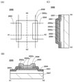
도 1의 (C)에, 회로(50)의 단면 구조의 개요도를 도시한다. 회로(50)는, 기판(100) 위의 회로(90)와, 회로(90) 위의 절연층(101)과, 절연층(101) 위의 회로(80)를 가진다. 즉, 회로(50)는, 회로(90)와 회로(80)가 적층된 구조를 가진다. 절연층(101)은 개구부를 가지며, 상기 개구부에는 도전층(102)이 설치되어 있다. 그리고, 회로(90)는 도전층(102)을 개재하여 회로(80)와 접속되어 있다. 1C, a schematic diagram of a cross-sectional structure of the
여기에서, 회로(80) 또는 회로(90)의 한쪽은, 다른쪽의 적어도 일부와 중첩되는 영역을 갖는 것이 바람직하다. 이것에 의해, 회로(50)의 면적의 증가를 억제하면서, 기억 회로로서 기능하는 회로(50)에 연산을 행하는 기능을 부가할 수 있다. 따라서, 반도체 장치(10)의 면적의 축소를 도모할 수 있다. 또한, 회로(80) 또는 회로(90)의 한쪽이, 다른쪽의 전면과 중첩되는 영역을 가짐으로써, 회로(50)의 면적을 더욱 축소시킬 수 있다. Here, it is preferable that one side of the
또한, 본 명세서 등에 있어서, X와 Y가 접속되어 있다, 라고 명시적으로 기재하는 경우에는, X와 Y가 전기적으로 접속되어 있는 경우와, X와 Y가 기능적으로 접속되어 있는 경우와, X와 Y가 직접 접속되어 있는 경우를 포함하는 것으로 한다. 따라서, 소정의 접속 관계, 예를 들면, 도면 또는 문장에 나타낸 접속 관계로 한정되지 않으며, 도면 또는 문장에 나타낸 접속 관계 이외의 것도 포함하는 것으로 한다. 여기에서, X, Y는, 대상물(예를 들면, 장치, 소자, 회로, 배선, 전극, 단자, 도전막, 층, 등)인 것으로 한다. In addition, in this specification and the like, when it is explicitly stated that X and Y are connected, when X and Y are electrically connected, when X and Y are functionally connected, and when X and It is assumed that the case where Y is directly connected is included. Therefore, it is not limited to a predetermined connection relationship, for example, a connection relationship shown in a drawing or text, but includes things other than a connection relationship shown in the drawing or text. Here, X and Y are assumed to be objects (eg, devices, elements, circuits, wirings, electrodes, terminals, conductive films, layers, etc.).
X와 Y가 전기적으로 접속되어 있는 경우의 일례로서는, X와 Y의 전기적인 접속을 가능하게 하는 소자(예를 들면, 스위치, 트랜지스터, 용량 소자, 인덕터, 저항 소자, 다이오드, 표시 소자, 발광 소자, 부하 등)가, X와 Y 사이에 1개 이상 접속되는 것이 가능하다. 또한, 스위치는, 온 오프가 제어되는 기능을 가지고 있다. 즉, 스위치는, 도통 상태(온 상태), 또는, 비도통 상태(오프 상태)가 되어, 전류를 흘려보낼지 흘려보내지 않을지를 제어하는 기능을 가지고 있다. 또는, 스위치는, 전류를 흘려보내는 경로를 선택하여 전환하는 기능을 가지고 있다. As an example of the case where X and Y are electrically connected, an element (for example, a switch, a transistor, a capacitor, an inductor, a resistance element, a diode, a display element, a light emitting element) which enables the electric connection of X and Y is possible. , load, etc.) can be connected between X and Y more than one. Moreover, the switch has a function by which ON/OFF is controlled. That is, the switch becomes a conduction state (on state) or a non-conduction state (off state), and has a function of controlling whether electric current flows or not. Alternatively, the switch has a function of selecting and switching the path through which the current flows.
또한, X와 Y가 기능적으로 접속되어 있는 경우의 일례로서는, X와 Y의 기능적인 접속을 가능하게 하는 회로(예를 들면, 논리 회로(인버터, NAND 회로, NOR 회로 등), 신호 변환 회로(DA 변환 회로, AD 변환 회로, 감마 보정 회로 등), 전위 레벨 변환 회로(전원 회로(승압 회로, 강압 회로 등), 신호의 전위 레벨을 바꾸는 레벨 시프터 회로 등), 전압원, 전류원, 전환 회로, 증폭 회로(신호 진폭 또는 전류량 등을 크게 할 수 있는 회로, 연산 증폭기, 차동 증폭 회로, 소스 폴로어 회로, 버퍼 회로 등), 신호 생성 회로, 기억 회로, 제어 회로 등)가, X와 Y 사이에 1개 이상 접속되는 것이 가능하다. 또한, 일례로서, X와 Y 사이에 다른 회로를 개재하고 있어도, X로부터 출력된 신호가 Y로 전달되는 경우에는, X와 Y는 기능적으로 접속되어 있는 것으로 한다. Moreover, as an example of the case where X and Y are functionally connected, a circuit (for example, a logic circuit (inverter, NAND circuit, NOR circuit, etc.) which enables functional connection of X and Y, a signal conversion circuit ( DA conversion circuit, AD conversion circuit, gamma correction circuit, etc.), potential level conversion circuit (power supply circuit (step-up circuit, step-down circuit, etc.), level shifter circuit that changes the potential level of a signal, etc.), voltage source, current source, switching circuit, amplification Circuits (circuits that can increase signal amplitude or amount of current, etc., operational amplifiers, differential amplifier circuits, source follower circuits, buffer circuits, etc.), signal generation circuits, memory circuits, control circuits, etc.) are separated by 1 between X and Y. More than one connection is possible. In addition, as an example, even if another circuit is interposed between X and Y, when the signal output from X is transmitted to Y, X and Y shall be functionally connected.
또한, X와 Y가 전기적으로 접속되어 있다, 라고 명시적으로 기재하는 경우에는, X와 Y가 전기적으로 접속되어 있는 경우(즉, X와 Y 사이에 다른 소자 또는 다른 회로를 개재하여 접속되어 있는 경우)와, X와 Y가 기능적으로 접속되어 있는 경우(즉, X와 Y 사이에 다른 회로를 개재하여 기능적으로 접속되어 있는 경우)와, X와 Y가 직접 접속되어 있는 경우(즉, X와 Y 사이에 다른 소자 또는 다른 회로를 개재하지 않고 접속되어 있는 경우)를 포함하는 것으로 한다. 즉, 전기적으로 접속되어 있다, 라고 명시적으로 기재하는 경우에는, 단순히, 접속되어 있다, 라고만 명시적으로 기재되어 있는 경우와 동일한 것으로 한다. In addition, when it is explicitly stated that X and Y are electrically connected, when X and Y are electrically connected (that is, X and Y are connected via another element or another circuit) case), when X and Y are functionally connected (that is, when functionally connected through another circuit between X and Y), and when X and Y are directly connected (that is, when X and Y are connected to each other) (when connected without interposing other elements or other circuits between Y) shall be included. In other words, the case where it is explicitly stated that it is electrically connected is the same as the case where only it is explicitly stated that it is simply connected.
또한, 예를 들면, 트랜지스터의 소스(또는 제 1 단자 등)가, Z1을 개재하여(또는 개재하지 않고), X와 전기적으로 접속되고, 트랜지스터의 드레인(또는 제 2 단자 등)이, Z2를 개재하여(또는 개재하지 않고), Y와 전기적으로 접속되어 있는 경우나, 트랜지스터의 소스(또는 제 1 단자 등)가, Z1의 일부에 직접적으로 접속되고, Z1의 다른 일부가 X와 직접적으로 접속되고, 트랜지스터의 드레인(또는 제 2 단자 등)이, Z2의 일부에 직접적으로 접속되고, Z2의 다른 일부가 Y와 직접적으로 접속되어 있는 경우에는, 이하와 같이 표현할 수 있다. Further, for example, the source (or the first terminal, etc.) of the transistor is electrically connected to X via (or without) Z1, and the drain (or the second terminal, etc.) of the transistor is connected to Z2 In the case of being electrically connected to Y through (or without intervening), or the source (or first terminal, etc.) of the transistor is directly connected to a part of Z1, and another part of Z1 is directly connected to X and the drain (or second terminal, etc.) of the transistor is directly connected to a part of Z2 and another part of Z2 is directly connected to Y, it can be expressed as follows.
예를 들면, 「X와 Y와 트랜지스터의 소스(또는 제 1 단자 등)와 드레인(또는 제 2 단자 등)은, 서로 전기적으로 접속되어 있고, X, 트랜지스터의 소스(또는 제 1 단자 등), 트랜지스터의 드레인(또는 제 2 단자 등), Y의 순서로 전기적으로 접속되어 있다.」라고 표현할 수 있다. 또는, 「트랜지스터의 소스(또는 제 1 단자 등)는, X와 전기적으로 접속되고, 트랜지스터의 드레인(또는 제 2 단자 등)은 Y와 전기적으로 접속되고, X, 트랜지스터의 소스(또는 제 1 단자 등), 트랜지스터의 드레인(또는 제 2 단자 등), Y는, 이 순서로 전기적으로 접속되어 있다」라고 표현할 수 있다. 또는, 「X는, 트랜지스터의 소스(또는 제 1 단자 등)와 드레인(또는 제 2 단자 등)을 개재하여, Y와 전기적으로 접속되고, X, 트랜지스터의 소스(또는 제 1 단자 등), 트랜지스터의 드레인(또는 제 2 단자 등), Y는, 이 접속 순서로 설치되어 있다」라고 표현할 수 있다. 이들 예와 같은 표현 방법을 사용하여, 회로 구성에 있어서의 접속 순서에 관해서 규정함으로써, 트랜지스터의 소스(또는 제 1 단자 등)와, 드레인(또는 제 2 단자 등)을, 구별하여, 기술적 범위를 결정할 수 있다. 또한, 이들 표현 방법은, 일례이며, 이들 표현 방법으로 한정되지 않는다. 여기에서, X, Y, Z1, Z2는, 대상물(예를 들면, 장치, 소자, 회로, 배선, 전극, 단자, 도전막, 층, 등)인 것으로 한다. For example, "X and Y, and the source (or first terminal, etc.) and drain (or second terminal, etc.) of the transistor are electrically connected to each other, and X, the source (or the first terminal, etc.) of the transistor; The drain (or the second terminal, etc.) of the transistor is electrically connected in the order of Y.” Or, "The source (or first terminal, etc.) of the transistor is electrically connected to X, the drain (or the second terminal, etc.) of the transistor is electrically connected to Y, and X, the source (or first terminal, etc.) of the transistor etc.), the drain (or the second terminal, etc.) of the transistor, and Y are electrically connected in this order". Or, "X is electrically connected to Y via a source (or a first terminal, etc.) and a drain (or a second terminal, etc.) of a transistor, X, a source (or a first terminal, etc.) of a transistor, a transistor The drain (or the second terminal, etc.) and Y of are provided in this connection order". By using the same expression method as in these examples and specifying the connection sequence in the circuit configuration, the source (or first terminal, etc.) and drain (or second terminal, etc.) of the transistor are distinguished and the technical scope is determined can decide In addition, these expression methods are an example, and are not limited to these expression methods. Here, it is assumed that X, Y, Z1, and Z2 are objects (eg, devices, elements, circuits, wirings, electrodes, terminals, conductive films, layers, etc.).
또한, 도면상 독립되어 있는 구성 요소들이 전기적으로 접속하고 있는 것처럼 도시되어 있는 경우라도, 1개의 구성 요소가, 복수의 구성 요소의 기능을 함께 가지고 있는 경우도 있다. 예를 들면, 배선의 일부가 전극으로서도 기능하는 경우에는, 하나의 도전막이, 배선의 기능, 및 전극의 기능 양쪽의 구성 요소의 기능을 함께 가지고 있다. 따라서, 본 명세서에 있어서의 접속이란, 이러한, 하나의 도전막이, 복수의 구성 요소의 기능을 함께 가지고 있는 경우도, 그 범주에 포함시킨다. In addition, even when it is illustrated as if independent components are electrically connected in the drawing, there is a case where one component has the function of a plurality of components together. For example, when a part of wiring also functions as an electrode, one conductive film has both the function of the wiring and the function of the constituent elements of both the function of the electrode. Therefore, the term "connection" in this specification also includes the case where such one conductive film has the function of a plurality of components together in the scope.
여기에서, 회로(90)는, 채널 형성 영역이 기판(100)의 일부에 형성되는 트랜지스터에 의해 구성할 수 있다. 이 경우, 기판(100)은 단결정 반도체를 갖는 기판으로 하는 것이 바람직하다. 이러한 기판(100)으로서는, 단결정 실리콘 기판이나 단결정 게르마늄 기판 등을 사용할 수 있다. 기판(100)을 단결정 반도체를 갖는 기판으로 함으로써, 회로(90)를, 채널 형성 영역에 단결정 반도체를 갖는 트랜지스터를 사용하여 형성할 수 있다. 채널 형성 영역에 단결정 반도체를 갖는 트랜지스터는 전류 공급 능력이 높기 때문에, 이러한 트랜지스터를 사용하여 회로(90)를 구성함으로써, 회로(90)에 있어서의 연산의 속도를 향상시킬 수 있다. Here, the
다음에, 회로(50)의 구성의 일례를, 도 2를 사용하여 설명한다. Next, an example of the configuration of the
도 2의 (A)는, 도 1에 있어서의 회로(50)의 구성의 일례를 도시하는 사시도이다. 회로(50)는, 기판(100) 위의 회로(90), 회로(110), 회로(120)와, 회로(90), 회로(110), 회로(120) 위의 절연층(101)과, 절연층(101) 위의 회로(80)를 가진다. 또한, 회로(80)는, 복수의 기억 회로(81)를 가진다. FIG. 2A is a perspective view showing an example of the configuration of the
회로(90)는, 연산 회로를 갖는 회로이며, 기억 회로(81)와 접속되어 있다. 회로(90)는, 기억 회로(81)에 기억된 데이터를 입력 신호로 하여 연산을 행하고, 연산의 결과를 회로(60)(도 1의 (B) 참조)로 출력할 수 있다. 또한, 회로(90)는, 회로(50)의 외부(예를 들면 도 1의 (B)에 있어서의 회로(40))로부터 입력된 데이터를 입력 신호로 하여 연산을 행할 수도 있다. The
회로(110)는, 복수의 기억 회로(81) 중, 특정한 기억 회로(81)를 선택하는 기능을 갖는 구동 회로이다. 구체적으로는, 회로(110)는, 특정한 기억 회로(81)와 접속된 배선에, 상기 특정 기억 회로(81)를 선택하기 위한 신호(이하, 선택 신호라고도 한다)를 공급하는 기능을 가진다. The
회로(120)는, 기억 회로(81)로의 데이터의 기록, 또는 기억 회로(81)에 기억된 데이터의 판독을 행하는 기능을 갖는 구동 회로이다. 구체적으로는, 회로(120)는, 특정 기억 회로(81)와 접속된 배선에, 상기 특정 기억 회로(81)에 기록하는 데이터에 대응하는 전위(이하, 기록 전위라고도 한다)를 공급하는 기능을 가진다. 또한, 회로(120)는, 특정 기억 회로(81)와 접속된 배선의 전위에 기초하여, 상기 특정 기억 회로(81)에 기억된 데이터를 판독하는 기능을 가진다. 또한, 회로(120)는, 기억 회로(81)와 접속된 배선에 소정의 전위를 공급하는 프리차지 기능을 가지고 있어도 좋다. The
여기에서, 기판(100)은, 단결정 반도체를 갖는 기판인 것이 바람직하다. 이것에 의해, 회로(90), 회로(110), 회로(120)를, 채널 형성 영역에 단결정 반도체를 갖는 트랜지스터에 의해 구성할 수 있다. 따라서, 회로(90), 회로(110), 회로(120)의 동작 속도를 향상시킬 수 있다. Here, the
회로(80)는, 복수의 기억 회로(81)를 메모리 셀로 한 셀 어레이에 의해 구성할 수 있다. 또한, 복수의 기억 회로(81)는 각각, 회로(90), 회로(110), 회로(120)와 접속되어 있다. The
여기에서, 기억 회로(81)는, 반도체막에 채널 형성 영역이 형성되는 트랜지스터에 의해 구성할 수 있다. 예를 들면, 기억 회로(81)는, 채널 형성 영역에 비단결정 반도체를 갖는 트랜지스터에 의해 구성할 수 있다. 비단결정 반도체로서는, 비정질 실리콘, 미결정 실리콘, 다결정 실리콘 등의 비단결정 실리콘이나, 비정질 게르마늄, 미결정 게르마늄, 다결정 게르마늄 등의 비단결정 게르마늄 등을 사용할 수 있다. 또한, 기억 회로(81)는, OS 트랜지스터에 의해 구성할 수 있다. 상기와 같은 반도체막에 채널 형성 영역이 형성되는 트랜지스터는, 절연층(101) 위에 형성하는 것이 가능하기 때문에, 기억 회로(81)를 절연층(101) 위에 형성하는 것이 가능해진다. 이것에 의해, 회로(50)를 회로(80)와 회로(90)가 적층된 구성으로 할 수 있다. Here, the
여기에서, 기억 회로(81)는, 특히 OS 트랜지스터를 사용하여 형성하는 것이 바람직하다. OS의 오프 전류는 매우 작기 때문에, 기억 회로(81)에 OS 트랜지스터를 사용함으로써, 회로(80)로의 전력 공급이 정지된 기간에 있어서도 기억 회로(81)에 기억된 데이터를 장기간에 걸쳐 유지할 수 있다. 따라서, 기억 회로(81)를, 비휘발성의 메모리 셀, 또는 리프레시 동작의 빈도가 매우 낮은 메모리 셀로서 사용할 수 있다. Here, the
또한, OS 트랜지스터는 미세화에 의해 고속 동작이 가능해진다. 이로 인해, 기억 회로(81)에 OS 트랜지스터를 사용함으로써, 기억 회로(81)의 동작 속도를 향상시킬 수 있다. 구체적으로는, 기억 회로(81)의 기록 속도 및 판독 속도를 10ns 이하, 보다 바람직하게는 5ns 이하, 더욱 바람직하게는 1ns 이하로 할 수 있다. 또한, OS 트랜지스터의 채널 길이는, 100nm 이하, 바람직하게는 60nm 이하, 보다 바람직하게는 40nm 이하, 더욱 바람직하게는 30nm 이하로 할 수 있다. In addition, high-speed operation of the OS transistor is enabled by miniaturization. For this reason, by using the OS transistor for the
여기에서, 회로(90)는, 회로(80)와 중첩되는 영역을 갖는 것이 바람직하다. 구체적으로는, 회로(90)는, 적어도 복수의 기억 회로(81) 중 어느 하나와 중첩되는 영역을 갖는 것이 바람직하다. 이것에 의해, 회로(50)의 면적 증가를 억제하면서, 기억 회로로서 기능하는 회로(50)에 연산을 행하는 기능을 부가할 수 있다. 또한, 회로(90)를, 복수의 기억 회로(81) 전부와 중첩되는 영역을 갖도록 배치함으로써, 회로(50)의 면적을 더욱 축소시킬 수 있다. 또한, 회로(110) 또는 회로(120)를, 적어도 복수의 기억 회로(81) 중 어느 하나와 중첩되는 영역을 갖도록 배치할 수도 있다. Here, the
또한, 도 2의 (A)에 있어서는, 기억 회로(81)를 갖는 회로(80)를 1층 설치한 구성으로 했지만, 이러한 회로를 2층 이상 설치한 구성으로 해도 좋다. 예를 들면, 회로(80) 위에 절연층을 설치하고, 상기 절연층 위에 기억 회로(81)를 갖는 회로를 추가로 설치해도 좋다. 이러한 구성으로 함으로써, 회로(50)의 면적 증가를 억제하면서, 기억 회로의 대용량화를 도모할 수 있다. In addition, in FIG.2(A), although it was set as the structure which provided the
또한, 도 2의 (A)에 있어서는, 회로(110) 및 회로(120)가 기판(100) 위에 설치된 예를 도시했지만, 이것으로 한정되지 않으며, 회로(110) 및 회로(120)를 절연층(101) 위에 설치해도 좋다(도 2의 (B)). 이 경우, 회로(110) 및 회로(120)는, 반도체막에 채널 형성 영역이 형성되는 트랜지스터에 의해 구성할 수 있지만, 특히, 오프 전류가 작고, 고속 동작이 가능한 OS 트랜지스터에 의해 구성하는 것이 바람직하다. In addition, in FIG. 2(A), although the example in which the
다음에, 회로(50)의 상면도의 예를 도 3에 도시한다. 또한, 도 3의 (C)는, 회로(110), 회로(120)가 기판(100) 위에 설치된 구조(도 2의 (A) 참조)의 상면도에 대응하고, 도 3의 (D)는, 회로(110), 회로(120)가 절연층(101) 위에 설치된 구조(도 2의 (B) 참조)의 상면도에 대응한다. Next, an example of the top view of the
도 3의 (A)에 도시하는 바와 같이, 회로(80)를, 회로(90)의 전면과 중첩되는 영역을 갖도록 배치할 수 있다. 이것에 의해, 회로(80)를 회로(90)와 동일 평면에 형성하는 경우와 비교하여, 회로(50)의 면적 증가를 억제할 수 있다. 또한, 회로(80)는, 회로(90)의 일부와 중첩되는 영역을 갖도록 배치해도 좋다. As shown in FIG. 3A , the
또한, 도 3의 (B)에 도시하는 바와 같이, 회로(90)를, 회로(80)의 전면과 중첩되는 영역을 갖도록 배치할 수도 있다. 또한, 회로(90)는, 회로(80)의 일부와 중첩되는 영역을 갖도록 배치해도 좋다. Further, as shown in FIG. 3B , the
또한, 도 3의 (C)에 도시하는 바와 같이, 회로(80)를, 회로(90)의 전면과 중첩되는 영역, 회로(110)의 전면과 중첩되는 영역, 및 회로(120)의 전면과 중첩되는 영역을 갖도록 배치할 수도 있다. 이 경우, 회로(50)의 면적 증가를 억제하면서, 도 3의 (A), (B)에 도시하는 구성보다도 회로(80)의 면적을 크게 할 수 있다. 이것에 의해, 기억 회로로서 기능하는 회로(80)의 대용량화를 도모할 수 있다. 또한, 회로(80)는, 회로(110)의 일부와 중첩되도록 배치해도 좋고, 회로(120)의 일부와 중첩되는 영역을 갖도록 배치해도 좋다. Further, as shown in FIG. 3C , the
또한, 도 3의 (D)에 도시하는 바와 같이, 회로(90)를, 회로(80)의 전면과 중첩되는 영역, 회로(110)의 전면과 중첩되는 영역, 및 회로(120)의 전면과 중첩되는 영역을 갖도록 배치할 수도 있다. 이 경우, 회로(50)의 면적 증가를 억제하면서, 도 3의 (A), (B)에 도시하는 구성보다도 회로(90)의 면적을 크게 할 수 있다. 이것에 의해, 회로(90)가 갖는 연산 회로의 수 및 종류를 늘릴 수 있어, 회로(90)에 있어서의 연산 속도의 향상, 또는 회로(90)에 있어서의 연산 종류의 증가를 도모할 수 있다. 또한, 회로(90)는, 회로(110)의 일부와 중첩되도록 배치해도 좋고, 회로(120)의 일부와 중첩되는 영역을 갖도록 배치해도 좋다. Further, as shown in FIG. 3D , the
다음에, 도 1에 있어서의 반도체 장치(10)의 동작의 일례를, 도 4의 흐름도를 사용하여 설명한다. 여기에서는 일례로서, 반도체 장치(10)를, 검출한 생체 정보가 정상값인지 이상값인지를 판별하는 것이 가능한 건강 관리 시스템으로서 사용하는 경우에 관해서 설명한다. Next, an example of the operation of the
우선, 회로(30)에 의해 회로(20)를 제어하여, 생체 정보를 검출한다(스텝 S1). 그 후, 검출한 생체 정보에 대응하는 아날로그 신호를, 회로(40)에 있어서 디지털 신호로 변환한다(스텝 S2). First, the
다음에, 회로(50)에 있어서, 생체 신호가 정상값인지 이상값인지를 판별한다(스텝 S3). 이 판별은, 회로(40)로부터 회로(50)에 입력된 생체 정보의 값과, 미리 회로(80)에 기억된 기준값을, 회로(90)에 있어서 비교함으로써 행한다. 예를 들면, 생체 정보로서 혈당값(BS)을 검출하는 경우에는, 소정의 혈당값(예를 들면, BS=126(mg/dl))을 기준값으로 하여 회로(80)에 기억해 둔다. 그리고, 회로(40)로부터 입력된 혈당값의 값을 기준값과 비교하여, 혈당값이 기준값 미만이면 정상값, 기준값 이상인 경우에는 이상값이라고 판단한다. Next, in the
스텝 S3에 있어서의 판별 결과, 생체 정보가 정상값이라고 판단된 경우에는, 회로(90)에 있어서 데이터 처리를 행한다(스텝 S4). 회로(90)에 있어서의 데이터 처리로서는, 예를 들면, 생체 정보의 변동량이나 평균값의 산출을 들 수 있다. As a result of the determination in step S3, when it is determined that the biometric information is a normal value, data processing is performed in the circuit 90 (step S4). The data processing in the
생체 정보의 변동량은, 어떤 시각에 있어서 검출한 생체 정보의 값과, 그 시각 이전에 검출한 생체 정보의 값의 차분을 산출함으로써 얻을 수 있다. 이 차분의 산출은, 회로(90)에 연산 회로로서 감산 회로를 설치함으로써 행할 수 있다. The variation amount of the biometric information can be obtained by calculating the difference between the value of the biometric information detected at a certain time and the value of the biometric information detected before that time. Calculation of this difference can be performed by providing a subtraction circuit as an arithmetic circuit in the
또한, 생체 정보의 평균값은, 어떤 시각까지 검출한 생체 정보의 값의 총합을 산출하고, 그 값을, 검출한 생체 정보의 개수로 나눔으로써 얻을 수 있다. 또한, 평균값의 산출은, 회로(90)에 연산 회로로서 가산 회로 및 제산 회로를 설치함으로써 행할 수 있다. In addition, the average value of biometric information can be obtained by calculating the total of the values of biometric information detected up to a certain time, and dividing the value by the number of detected biometric information. In addition, the calculation of the average value can be performed by providing an addition circuit and a division circuit as an arithmetic circuit in the
그 후, 데이터 처리에 의해 얻어진 결과를 회로(80)에 기억한다(스텝 S5). 또한, 회로(80)에 기억된 데이터는, 회로(60)를 제어함으로써, 회로(70)로부터 외부로 송신할 수 있다. Thereafter, the result obtained by the data processing is stored in the circuit 80 (step S5). In addition, the data stored in the
또한, 회로(90)에 있어서의 데이터 처리를 행하지 않으며, 회로(40)로부터 입력된 생체 정보를 그대로 회로(80)에 기억, 또는 회로(60)로 출력하는 경우에는, 스텝 S4의 데이터 처리를 생략할 수 있다. In the case where the data processing in the
스텝 S3에 있어서의 판별 결과, 생체 정보가 이상값이라고 판단된 경우, 이상값인 것을 알리는 신호(이하, 인터럽트 신호라고도 한다)가 회로(50)로부터 회로(60)로 출력된다(스텝 S6). 그리고, 인터럽트 신호를 수신한 회로(60)는 회로(70)를 제어하고, 회로(70)는 이상값을 검출한 신호를 외부로 송신한다(스텝 S7). As a result of the determination in step S3, when it is determined that the biometric information is an abnormal value, a signal indicating that the biometric information is an abnormal value (hereinafter also referred to as an interrupt signal) is output from the
또한, 생체 정보가 이상값인 경우도, 정상값인 경우와 같은 데이터 처리(스텝 S8) 및 회로(80)로의 데이터의 기억(스텝 S9)을 행할 수 있다. 이 때, 회로(80)에는, 이상값이라고 판단된 생체 정보의 값이나, 이상값을 검출한 시각 등을 기억할 수 있다. 이들 정보는, 회로(70)로부터 외부로 송신할 수 있다. Also, even when the biometric information is an abnormal value, the same data processing (step S8) and storage of the data in the circuit 80 (step S9) as in the case of a normal value can be performed. At this time, the
이상과 같이, 본 발명의 일 형태에 있어서는, 회로(50)를, 연산을 행하는 기능을 구비한 기억 회로로서 사용할 수 있다. 이로 인해, 회로(50)는, 회로(50)에 기억된 데이터나 회로(40)로부터 입력된 데이터에 더하여, 이들 데이터를 입력 신호로 하여 연산을 행한 결과를 회로(60)로 출력할 수 있다. 이것에 의해, 본래 회로(60)에 있어서 행해야 하는 연산을 회로(50)에 있어서 행할 수 있어, 회로(60)에 있어서의 연산의 부담을 저감시킬 수 있다. 또한, 회로(50)와 회로(60) 사이에 있어서 행해지는 데이터의 송수신 횟수를 감소시킬 수 있다. 따라서, 반도체 장치(10)의 동작 속도를 향상시킬 수 있다. As described above, in one embodiment of the present invention, the
또한, 본 발명의 일 형태에 있어서는, 회로(80) 또는 회로(90)의 한쪽이, 다른쪽의 적어도 일부와 중첩되는 영역을 갖는 구성으로 할 수 있다. 이것에 의해, 회로(50)의 면적 증가를 억제하면서, 기억 회로로서 기능하는 회로(50)에 연산을 행하는 기능을 부가할 수 있다. 따라서, 반도체 장치(10)의 면적 축소를 도모할 수 있다. Moreover, in one aspect of this invention, it can be set as the structure in which one of the
또한, 본 실시형태는 다른 실시형태의 기재와 적절히 조합할 수 있다. 따라서, 본 실시형태 중에서 서술하는 내용(일부 내용이라도 좋다)은, 그 실시형태에서 서술하는 다른 내용(일부 내용이라도 좋다), 및/또는, 하나 또는 복수의 다른 실시형태에서 서술하는 내용(일부 내용이라도 좋다)에 대해, 적용, 조합, 또는 전환 등을 행할 수 있다. 또한, 실시형태 중에서 서술하는 내용이란, 각각의 실시형태에 있어서, 여러가지 도면을 사용하여 서술하는 내용, 또는 명세서에 기재되는 문장을 사용하여 서술하는 내용을 말한다. 또한, 어떤 하나의 실시형태에 있어서 서술하는 도면(일부라도 좋다)은, 그 도면의 다른 부분, 그 실시형태에 있어서 서술하는 다른 도면(일부라도 좋다), 및/또는, 하나 또는 복수의 다른 실시형태에 있어서 서술하는 도면(일부라도 좋다)에 대해, 조합함으로써, 더 많은 도면을 구성시킬 수 있다. 이것은, 이하의 실시형태에 있어서도 마찬가지이다. In addition, this embodiment can be suitably combined with the description of another embodiment. Therefore, the content (partial content may be sufficient) described in this embodiment is other content (partial content may be sufficient) described in the embodiment, and/or content described in one or a plurality of other embodiments (partial content) may be applied), application, combination, or conversion can be performed. In addition, in each embodiment, the content described in embodiment means the content described using various drawings, or the content described using the sentence described in the specification. In addition, a drawing (part may be sufficient) described in one embodiment is another part of the drawing, another drawing (part may be sufficient) described in the embodiment, and/or one or a plurality of other implementations More drawings can be configured by combining the drawings (parts may be sufficient) described in the form. This is also the same in the following embodiment.
(실시형태 2)(Embodiment 2)
본 실시형태에서는, 본 발명의 일 형태에 따른 구성의 구체예에 관해서 설명한다. 여기에서는 특히, 반도체 장치(10)가, 검출된 생체 정보가 정상값인지 이상값인지를 판별하는 건강 관리 시스템으로서의 기능을 갖는 구성에 관해서 설명한다. In the present embodiment, a specific example of the configuration according to one embodiment of the present invention will be described. In particular, a configuration in which the
도 5에, 회로(50)의 구성의 일례를 도시한다. 회로(50)는, 회로(80), 회로(90), 회로(110), 회로(120), 복수의 회로(83)를 가진다. 또한, 도 5에 있어서는 설명의 편의상, 회로(80)와 회로(90)를 동일한 평면에 도시하고 있지만, 실제로는 도 1 내지 도 3에 도시하는 바와 같이, 회로(80)와 회로(90)는 서로 중첩되도록 적층되어 있다. In FIG. 5, an example of the structure of the
회로(80)는, 복수의 기억 회로(81) 및 복수의 기억 회로(82)를 가진다. 여기에서는, 회로(80)가 n행 m열(n, m은 자연수)의 기억 회로(81)(기억 회로(81) [1,1] 내지 [n, m])와, 1행 m열의 기억 회로(82)(기억 회로(82) [1] 내지 [m])를 갖는 구성을 나타낸다. 또한, 기억 회로(82)는 2행 이상 설치되어 있어도 좋다. 기억 회로(81) 및 기억 회로(82)는 메모리 셀로서 기능하고, 회로(80)는 복수의 메모리 셀에 의해 구성된 셀 어레이로서 기능한다. The
여기에서, 회로(80)는 n행 m열의 기억 회로(81)를 갖기 때문에, m 비트의 데이터를 n종류 기억할 수 있다. 따라서, 상이한 시각이나 조건에 있어서 검출한 m 비트의 생체 정보의 값을 n종류 기억할 수 있다. 또한, 기억 회로(81)의 열의 수(m)는, 검출하는 생체 정보에 맞춰서 자유롭게 결정할 수 있다. 예를 들면, 생체 정보로서 혈당값을 검출하는 경우, m=8로서, BS=0 내지 255(mg/dl)의 범위의 수치를 기억하는 구성으로 할 수 있다. Here, since the
또한, 기억 회로(81)는, OS 트랜지스터를 사용하여 구성하는 것이 바람직하다. 이것에 의해, 기억 회로(81)에 기억된 생체 정보를 장기간에 걸쳐 유지하는 것이 가능해져, 기억 회로(81)를 비휘발성의 메모리 셀, 또는 리프레시 동작의 빈도가 매우 낮은 메모리 셀로서 사용할 수 있다. In addition, it is preferable to configure the
또한, 회로(80)가 갖는 1행 m열의 기억 회로(82)에는, m 비트의 데이터를 1종류 기억할 수 있다. 여기에서, 기억 회로(82) [1] 내지 [m]에는, 생체 정보의 기준값이 되는 m 비트의 데이터를 기억할 수 있다. 이 기준값은, 예를 들면, 생체 정보의 정상값과 이상값의 경계가 되는 값(정상값의 상한값 또는 하한값)으로 할 수 있다. 예를 들면, 생체 정보로서 혈당값을 검출하는 경우, 혈당값의 정상값의 상한값으로서 BS=126(mg/dl)을 기억할 수 있다. In addition, one type of m-bit data can be stored in the
또한, 여기에서는 기억 회로(82)가 1행 설치된 예에 관해서 서술하지만, 복수행 설치되어 있어도 좋다. 이 경우, 복수의 기준값을 기억할 수 있기 때문에, 기억 회로(82)에는, 생체 정보의 상한값 및 하한값을 기억하는 것이나, 복수의 상한값, 또는 복수의 하한값을 기억하는 것이 가능해진다. 또한, 기억 회로(82)의 행수는 특별히 한정되지 않으며, 1 이상의 임의의 수를 선택할 수 있다. In addition, although the example in which the
예를 들면, 생체 정보로서 혈당값을 검출하는 경우, m열의 기억 회로(82)를 3행 설치하고, 1행째의 기억 회로(82)에는 제 1 상한값(예를 들면, BS=110(mg/dl))을 기억하고, 2행째의 기억 회로(82)에는 제 2 상한값(예를 들면, BS=116(mg/dl))을 기억하고, 3행째의 기억 회로(82)에는 제 3 상한값(예를 들면, BS=126(mg/dl))을 기억할 수 있다. 이것에 의해, 검출된 혈당값과 제 1 내지 제 3 상한값을 비교할 수 있어, 생체 정보의 이상을 단계적으로 판별할 수 있다. For example, when a blood glucose value is detected as biometric information, three rows of
여기에서, 기억 회로(82)는, 특히 OS 트랜지스터를 사용하여 형성하는 것이 바람직하다. OS의 오프 전류는 매우 작기 때문에, 기억 회로(82)에 OS 트랜지스터를 사용함으로써, 회로(80)로의 전력 공급이 정지된 기간에 있어서도 기억 회로(82)에 기억된 데이터를 장기간에 걸쳐 유지할 수 있다. 따라서, 기억 회로(82)를 비휘발성의 메모리 셀, 또는 리프레시 동작의 빈도가 매우 낮은 메모리 셀로서 사용할 수 있다. 이로 인해, 한번 기억 회로(82)에 기준값의 기록을 행한 후에는, 회로(80)로의 전력 공급이 정지된 기간에 있어서도, 상기 기준값을 장기간 유지할 수 있다. Here, the
회로(110)는, 복수의 배선(111)(배선(111) [1] 내지 [n])을 개재하여 기억 회로(81)와 접속되어 있다. 또한, 회로(110)는, 배선(112)을 개재하여 기억 회로(82)와 접속되어 있다. 회로(110)는, 선택 신호를 배선(111) 또는 배선(112)에 공급하는 기능을 갖는 구동 회로이다. The
회로(120)는, 복수의 배선(121)(배선(121) [1] 내지 [m])을 개재하여, 기억 회로(81) 및 기억 회로(82)와 접속되어 있다. 회로(120)는, 기억 회로(81) 또는 기억 회로(82)에 기록하는 데이터에 대응하는 전위를 배선(121)에 공급하는 기능과, 배선(121)의 전위에 기초하여, 기억 회로(81) 또는 기억 회로(82)에 기억된 데이터를 판독하는 기능을 갖는 구동 회로이다. 또한, 회로(120)는, 배선(121)에 소정의 전위를 공급하는 프리차지 기능을 가지고 있어도 좋다. The
복수의 회로(83)(회로(83) [1] 내지 [m])는, 각각 배선(113), 배선(121), 회로(90)와 접속되어 있다. 회로(83)는, 기억 회로(81)에 기억된 데이터의 회로(90)로의 출력을 제어하는 스위치로서의 기능을 가진다. 회로(83)는, 배선(113)의 전위에 의해 도통 상태가 제어되어, 회로(90)에 있어서 연산을 행할 때에 도통 상태가 된다. The plurality of circuits 83 (circuits 83 [1] to [m]) are respectively connected to the
회로(83)는, 예를 들면 트랜지스터 등에 의해 구성할 수 있다. 회로(83)를 트랜지스터로 하는 경우, 상기 트랜지스터의 게이트가 배선(113)과 접속되고, 소스 또는 드레인의 한쪽이 배선(121)과 접속되고, 소스 또는 드레인의 다른쪽이 회로(90)와 접속된 구성으로 하면 좋다. 이 경우, 배선(113)의 전위에 의해 트랜지스터의 도통 상태가 제어된다. 트랜지스터를 도통 상태로 함으로써, 기억 회로(81)에 기억된 데이터를 회로(90)로 출력하여, 회로(90)에 있어서의 연산을 실행할 수 있다. The
또한, 회로(83)로서 트랜지스터를 사용하는 경우에는, OS 트랜지스터를 사용할 수 있다. OS 트랜지스터는 오프 전류가 매우 낮기 때문에, 회로(90)에 있어서의 연산을 실행하지 않는 기간, 즉 OS 트랜지스터가 비도통 상태인 기간에 있어서, 배선(121)과 회로(90) 사이의 전하의 이동을 대폭 억제할 수 있다. In addition, when a transistor is used as the
또한, 본 명세서 등에 있어서, 트랜지스터의 소스란, 활성층으로서 기능하는 반도체의 일부인 소스 영역, 또는 상기 반도체에 접속된 소스 전극을 의미한다. 마찬가지로, 트랜지스터의 드레인이란, 상기 반도체의 일부인 드레인 영역, 또는 상기 반도체에 접속된 드레인 전극을 의미한다. 또한, 게이트는 게이트 전극을 의미한다. In addition, in this specification and the like, the source of a transistor means a source region that is a part of a semiconductor that functions as an active layer, or a source electrode connected to the semiconductor. Similarly, the drain of the transistor means a drain region that is a part of the semiconductor or a drain electrode connected to the semiconductor. In addition, the gate means a gate electrode.
또한, 트랜지스터가 갖는 소스와 드레인은, 트랜지스터의 도전형 및 각 단자에 부여되는 전위의 고저에 의해, 그 호칭이 교체된다. 일반적으로, n채널형 트랜지스터에서는, 낮은 전위가 부여되는 단자가 소스라고 불리고, 높은 전위가 부여되는 단자가 드레인이라고 불린다. 또한, p채널형 트랜지스터에서는, 낮은 전위가 부여되는 단자가 드레인이라고 불리고, 높은 전위가 부여되는 단자가 소스라고 불린다. 본 명세서에서는, 편의상, 소스와 드레인이 고정되어 있는 것으로 가정하고, 트랜지스터의 접속 관계를 설명하는 경우가 있지만, 실제로는 상기 전위의 관계에 따라 소스와 드레인의 호칭이 교체된다. In addition, the names of the source and drain of a transistor change depending on the conductivity type of the transistor and the level of potential applied to each terminal. In general, in an n-channel transistor, a terminal to which a low potential is applied is called a source, and a terminal to which a high potential is applied is called a drain. Further, in the p-channel transistor, a terminal to which a low potential is applied is called a drain, and a terminal to which a high potential is applied is called a source. In this specification, for convenience, it is assumed that the source and the drain are fixed, and the connection relationship of the transistors is described in some cases.
회로(90)는, 회로(91), 회로(92)를 가진다. 회로(91)는, 연산을 행하는 기능을 갖는 회로이고, 1 이상의 연산 회로를 가진다. 연산 회로는, NOT 회로, AND 회로, OR 회로, NAND 회로, NOR 회로, XOR 회로, XNOR 회로 등의 논리 회로에 의해 구성할 수 있다. 또한, 이러한 논리 회로를 조합하여, 비교 회로, 가산 회로, 감산 회로, 승산 회로, 제산 회로 등으로 구성해도 좋다. 여기에서는, 회로(91)가 비교 회로를 갖는 경우에 관해서 설명한다. The
회로(91)는, 기억 회로(82), 회로(83), 회로(92)와 접속되어 있다. 회로(91)에는, 기억 회로(81)에 기억된 데이터가 회로(83)를 개재하여 입력되는 동시에, 기억 회로(82)에 기억된 데이터가 입력된다. 그리고, 회로(91)는, 이들 데이터의 대소를 비교하여, 그 비교 결과에 대응하는 신호를 회로(92)로 출력하는 기능을 가진다. 예를 들면, 회로(91)는, 기억 회로(81) [1,1] 내지 [n,1] 중 어느 하나에 기억된 데이터와, 기억 회로(82) [1]에 기억된 데이터를 비교할 수 있다. The
여기에서, 기억 회로(81)에는 회로(20)(도 1의 (A), (B) 참조)에 의해 검출된 생체 정보의 값이 기억되어 있고, 기억 회로(82)에는 소정의 기준값이 기억되어 있다. 그리고, 회로(91)는, 특정한 행의 기억 회로(81)에 기억된 m 비트의 생체 정보의 값과, 기억 회로(82)에 기억된 m 비트의 기준값을 비교할 수 있다. 이것에 의해, 검출된 생체 정보가 정상값인지 이상값인지를 판별할 수 있다. 예를 들면, 기억 회로(81)에 기억된 생체 정보의 값이 기억 회로(82)에 기억된 기준값 이상일 때, 이상값이라고 판단한다. Here, the
회로(92)는, 회로(91)에 있어서의 비교 결과, 생체 정보가 이상값이라고 판단되었을 때에, 회로(60)(도 1 참조)에 인터럽트 신호를 출력하는 기능을 가진다. 예를 들면, 회로(92)는, 생체 정보가 정상값인 경우에는 데이터 ”1”을 출력하고, 이상값인 경우에는 인터럽트 신호로서 데이터 ”0”을 출력하는 기능을 가진다. 그리고, 데이터 ”0”이 회로(60)로 출력되면, 회로(60)에 의해 회로(70)가 제어되어, 회로(70)로부터 외부로 이상값인 신호가 송신된다. The
또한, 복수의 회로(83)는, 회로(90)와 동일한 층(도 1의 (C), 도 2의 (A), (B)에 있어서의 기판(100) 위)에 설치되어 있어도 좋고, 회로(80)와 동일한 층(도 1의 (C), 도 2의 (A), (B)에 있어서의 절연층(101) 위)에 설치되어 있어도 좋다. 여기에서, 회로(83)로서 OS 트랜지스터를 사용하는 경우에는, 회로(83)를 회로(80)와 동일한 층에 설치하는 것이 바람직하다. 이 경우, 회로(83)를 구성하는 OS 트랜지스터를 기억 회로(81) 및 기억 회로(82)가 갖는 OS 트랜지스터와 동일 공정으로 제작할 수 있다. In addition, the plurality of
다음에, 기억 회로(81) 및 기억 회로(82)의 구체적인 구성의 일례를, 도 6에 도시한다. Next, an example of the specific structure of the
도 6의 (A)에, 기억 회로(81)의 구성예를 도시한다. 기억 회로(81)는, 트랜지스터(201), 용량 소자(202)를 가진다. 트랜지스터(201)의 게이트는 배선(111)과 접속되고, 소스 또는 드레인의 한쪽은 배선(121)과 접속되고, 소스 또는 드레인의 다른쪽은 노드(M1)와 접속되어 있다. 용량 소자(202)의 한쪽의 전극은 노드(M1)와 접속되고, 다른쪽의 전극은 소정의 전위가 공급되는 배선(203)과 접속되어 있다. 또한, 여기에서는, 트랜지스터(201)가 n채널형인 경우를 나타내지만, 이것으로 한정되지 않으며, 트랜지스터(201)는 n채널형 트랜지스터라도 p채널형 트랜지스터라도 좋다. 또한, 배선(203)은, 고전위 전원선이라도 저전위 전원선(접지선 등)이라도 좋다. 기억 회로(81)에는, 생체 정보를 기억할 수 있다. Fig. 6A shows a configuration example of the
여기에서, 트랜지스터(201)로서 OS 트랜지스터를 사용한다. 도면 중, 「OS」의 기호를 붙인 트랜지스터는 OS 트랜지스터이다(이하 동일). OS 트랜지스터는 오프 전류가 매우 낮기 때문에, 트랜지스터(201)가 비도통 상태인 기간에 있어서, 노드(M1)의 전위를 장시간에 걸쳐 유지할 수 있다. 이로 인해, 기억 회로(81)를, 비휘발성의 메모리 셀, 또는 리프레시 동작의 빈도가 현저하게 낮은 메모리 셀로서 사용할 수 있다. Here, an OS transistor is used as the
또한, OS 트랜지스터는 미세화에 의해 고속 동작이 가능해진다. 이로 인해, 트랜지스터(201)로서 OS 트랜지스터를 사용함으로써, 기억 회로(81)의 동작 속도를 향상시킬 수 있다. In addition, high-speed operation of the OS transistor is enabled by miniaturization. For this reason, by using an OS transistor as the
다음에, 도 6의 (A)에 도시하는 기억 회로(81)의 동작에 관해서 설명한다. Next, the operation of the
우선, 배선(121)에 기록 전위를 공급한다. 그리고, 배선(203)의 전위를 일정한 전위로 유지한 후, 배선(111)의 전위를 트랜지스터(201)가 도통 상태가 되는 전위로 하여, 트랜지스터(201)를 도통 상태로 한다. 이것에 의해, 배선(121)의 전위가 노드(M1)에 공급된다(데이터의 기록). First, a write potential is supplied to the
다음에, 배선(111)의 전위를 트랜지스터(201)가 비도통 상태가 되는 전위로 하여, 트랜지스터(201)를 비도통 상태로 한다. 이것에 의해, 노드(M1)가 부유 상태가 되어, 노드(M1)의 전위가 유지된다(데이터의 유지). 여기에서, 트랜지스터(201)는 OS 트랜지스터이고, 오프 전류가 매우 작기 때문에, 노드(M1)의 전위를 장시간에 걸쳐 유지할 수 있다. Next, the potential of the
다음에, 배선(121)을 부유 상태로 하고, 배선(203)의 전위를 일정한 전위로 유지한 후, 배선(111)의 전위를 트랜지스터(201)가 도통 상태가 되는 전위로 하여, 트랜지스터(201)를 도통 상태로 한다. 이것에 의해, 노드(M1)의 전위가 배선(121)에 공급된다. 이 때, 배선(121)의 전위는, 노드(M1)의 전위에 따라 상이한 전위가 된다. 이 때의 배선(121)의 전위를 판독함으로써, 기억 회로(81)에 기억되어 있는 데이터의 판독이 가능해진다. Next, the
또한, 데이터의 재기록은, 상기 데이터의 기록 및 유지와 같은 동작에 의해 행할 수 있다. In addition, data rewriting can be performed by the same operations as the above data recording and retention.
또한, 도 6의 (B)에, 기억 회로(82)의 구성예를 도시한다. 기억 회로(82)는, 트랜지스터(211), 용량 소자(212), 회로(214)를 가진다. 트랜지스터(211)의 게이트는 배선(112)과 접속되고, 소스 또는 드레인의 한쪽은 배선(121)과 접속되고, 소스 또는 드레인의 다른쪽은 노드(M2)와 접속되어 있다. 용량 소자의 한쪽의 전극은 노드(M2)와 접속되고, 다른쪽의 전극은 소정의 전위가 공급되는 배선(213)과 접속되어 있다. 회로(214)의 입력 단자는 노드(M2)와 접속되고, 출력 단자는 회로(90)와 접속되어 있다. 또한, 트랜지스터(211)는 OS 트랜지스터로 한다. 여기에서는, 트랜지스터(211)가 n채널형인 경우를 나타내지만, 이것으로 한정되지 않고, 트랜지스터(211)는 n채널형 트랜지스터라도 p채널형 트랜지스터라도 좋다. 또한, 배선(213)은, 고전위 전원선이라도 저전위 전원선(접지선 등)이라도 좋다. 6B shows a configuration example of the
기억 회로(82)는, 도 6의 (A)에 있어서의 기억 회로(81)와 같은 동작에 의해, 데이터의 기록, 유지, 재기록을 행할 수 있다. 기억 회로(82)에는, 기억 회로(81)에 기억된 생체 정보의 값과 비교하기 위한 기준값을 기억할 수 있다. The
또한, 기억 회로(82)는, 노드(M2)에 유지된 전위에 대응하는 데이터를, 회로(214)를 개재하여 회로(90)로 출력할 수 있다. 여기에서, 회로(214)는, 노드(M2)의 전위를 유지하면서, 노드(M2)의 전위에 대응한 신호를 출력하는 기능을 갖는 것이면, 특별히 한정되지 않는다. 회로(214)로서는, 예를 들면 인버터나 아날로그 스위치 등의 논리 소자를 사용할 수 있다. 회로(214)로서 인버터를 사용하는 경우에는, 상기 인버터의 입력 단자는 노드(M2)와 접속되고, 출력 단자는 회로(90)와 접속된다. 그리고, 회로(90)에 있어서의 연산에는, 인버터의 출력 단자로부터 출력된 신호의 반전 신호를 사용할 수 있다. Further, the
또한, 도 6의 (C)에 도시하는 바와 같이, 기억 회로(82)는 트랜지스터(215)를 가지고 있어도 좋다. 트랜지스터(215)의 게이트는 배선(216)과 접속되고, 소스 또는 드레인의 한쪽은 노드(M2)와 접속되고, 소스 또는 드레인의 다른쪽은 회로(214)의 입력 단자와 접속되어 있다. 또한, 트랜지스터(215)는 OS 트랜지스터이다. Further, as shown in FIG. 6C , the
배선(216)은, 회로(90)에 있어서의 비교 연산이 행해질 때, 트랜지스터(215)를 도통 상태로 하기 위한 신호가 공급되는 배선이다. 이로 인해, 배선(216)에는, 도 5에 있어서의 배선(113)에 공급되는 신호와 동기한 신호를 공급할 수 있다. 예를 들면, 배선(216)을 배선(113)과 접속해도 좋고, 트랜지스터(215)의 게이트에 직접 배선(113)을 접속해도 좋다. 또한, 배선(216)에 배선(113)의 반전 신호가 공급되는 구성으로 해도 좋다. The
회로(90)에 있어서의 비교 연산이 실행될 때, 트랜지스터(215)는 도통 상태가 된다. 한편, 회로(90)에 있어서의 비교 연산이 행해지지 않는 기간에 있어서는, 트랜지스터(215)는 비도통 상태가 된다. 여기에서, OS 트랜지스터인 트랜지스터(215)는 오프 전류가 매우 낮기 때문에, 노드(M2)의 전위가 회로(214)를 개재하여 회로(90)로 리크되는 것을 방지할 수 있다. 따라서, 노드(M2)에 유지된 전위를 장기간 유지할 수 있다. When the comparison operation in the
다음에, 기억 회로(81) 및 기억 회로(82)의 다른 구성예를, 도 7에 도시한다. Next, another structural example of the
도 7의 (A)에, 기억 회로(81)의 구성예를 도시한다. 기억 회로(81)는, 트랜지스터(221), 트랜지스터(222), 용량 소자(223)를 가진다. 트랜지스터(221)의 게이트는 배선(111)과 접속되고, 소스 또는 드레인의 한쪽은 배선(121)과 접속되고, 소스 또는 드레인의 다른쪽은 노드(M3)와 접속되어 있다. 트랜지스터(222)의 게이트는 노드(M3)와 접속되고, 소스 또는 드레인의 한쪽은 배선(121)과 접속되고, 소스 또는 드레인의 다른쪽은 배선(122)과 접속되어 있다. 용량 소자(223)의 한쪽의 전극은 노드(M3)와 접속되고, 다른쪽의 전극은 소정의 전위가 공급되는 배선(224)과 접속되어 있다. 여기에서는, 트랜지스터(221)로서 OS 트랜지스터를 사용한다. 또한, 배선(122)은, 회로(120)(도 5 참조)와 접속되어 있다. Fig. 7A shows a configuration example of the
또한, 여기에서는 트랜지스터(221) 및 트랜지스터(222)가 n채널형인 경우를 나타내지만, 이것으로 한정되지 않으며, 트랜지스터(221), 트랜지스터(222)는 각각, n채널형 트랜지스터라도 p채널형 트랜지스터라도 좋다. 또한, 배선(224)은, 일정한 전위가 공급되는 배선이라도, 2종류 이상의 전위가 공급되는 배선이라도 좋다. 또한, 일정한 전위가 공급되는 배선은, 고전위 전원선이라도 저전위 전원선(접지선 등)이라도 좋다. In addition, although the case where the
여기에서, 트랜지스터(222)에는, 채널 형성 영역에 단결정 반도체를 갖는 트랜지스터를 사용할 수 있다. 이 경우, 트랜지스터(222)의 전류 공급 능력을 향상시킬 수 있어, 기억 회로(81)의 고속 동작이 가능해진다. 또한, 트랜지스터(222)에는, OS 트랜지스터를 사용할 수 있다. 이 경우, 트랜지스터(222)를 트랜지스터(221)와 동일 공정으로 제작할 수 있다. Here, as the
다음에, 도 7의 (A)에 도시하는 기억 회로(81)의 동작에 관해서 설명한다. Next, the operation of the
우선, 배선(111)의 전위를, 트랜지스터(221)가 도통 상태가 되는 전위로 하여, 트랜지스터(221)를 도통 상태로 한다. 이것에 의해, 배선(121)의 전위가 노드(M3)에 부여된다. 즉, 트랜지스터(222)의 게이트 전극에는 소정의 전하가 부여된다(데이터의 기록). First, the potential of the
그 후, 배선(111)의 전위를 트랜지스터(221)가 비도통 상태가 되는 전위로 하여, 트랜지스터(221)를 비도통 상태로 함으로써, 노드(M3)가 부유 상태가 되어, 노드(M3)의 전위가 유지된다(데이터의 유지). Thereafter, the potential of the
다음에, 배선(122)의 전위를 일정한 전위로 유지한 후, 배선(224)의 전위를 소정의 전위(판독 전위)로 하면, 노드(M3)에 유지된 전하량에 따라, 배선(121)은 상이한 전위가 된다. 일반적으로, 트랜지스터(222)를 n채널형으로 하면, 트랜지스터(222)의 게이트의 전위가 하이 레벨인 경우의 겉보기 임계값(Vth_H)은, 트랜지스터(222)의 게이트의 전위가 로우 레벨인 경우의 겉보기 임계값(Vth_L)보다 낮아지기 때문이다. 여기에서, 겉보기 임계값 전압이란, 트랜지스터(222)를 도통 상태로 하기 위해서 필요한 배선(224)의 전위를 말하는 것으로 한다. 따라서, 배선(224)의 전위를 Vth_H와 Vth_L 사이의 전위(V0)로 함으로써, 노드(M3)의 전위를 판별할 수 있다. 예를 들면, 노드(M3)의 전위가 하이 레벨인 경우에는, 배선(224)의 전위가 V0(>Vth_H)가 되면, 트랜지스터(222)는 도통 상태가 된다. 한편, 노드(M3)의 전위가 로우 레벨인 경우에는, 배선(224)의 전위가 V0(<Vth_L)가 되어도, 트랜지스터(222)는 비도통 상태 그대로가 된다. 이로 인해, 배선(121)의 전위를 판독함으로써, 기억 회로(81)에 기억되어 있는 데이터의 판독이 가능해진다. Next, when the potential of the
또한, 데이터의 판독을 행하지 않는 경우에는, 노드(M3)의 전위에 관계없이 트랜지스터(222)가 비도통 상태가 되는 전위, 즉, Vth_H보다 작은 전위를 배선(224)에 부여하면 좋다. In addition, when data is not read, a potential at which the
또한, 데이터의 재기록은, 상기 데이터의 기록 및 유지와 같은 동작에 의해 행할 수 있다. In addition, data rewriting can be performed by the same operations as the above data recording and retention.
여기에서, 트랜지스터(221)의 소스 또는 드레인의 한쪽은, 트랜지스터(222)의 게이트와 접속됨으로써, 비휘발성 메모리로서 사용되는 플로팅 게이트형 트랜지스터의 플로팅 게이트와 같은 기능을 가진다. 이로 인해, 노드(M3)를, 플로팅 게이트부(FG)라고 부르는 경우가 있다. 트랜지스터(221)가 비도통 상태인 경우, 플로팅 게이트부(FG)는 절연체 중에 매설된 것으로 간주할 수 있고, 플로팅 게이트부(FG)에는 전하가 유지된다. 트랜지스터(221)의 오프 전류는, 채널 형성 영역에 단결정 반도체를 갖는 트랜지스터의 오프 전류의 10만분의 1 이하이기 때문에, 트랜지스터(221)의 리크에 의해 플로팅 게이트부(FG)에 축적된 전하가 소실되는 양은 매우 작다. 또는, 장기간에 걸쳐, 플로팅 게이트부(FG)에 축적된 전하의 소실을 무시하는 것이 가능하다. 그 결과, OS 트랜지스터인 트랜지스터(221)에 의해, 비휘발성의 기억 장치, 또는, 전원의 공급없이 데이터를 대단히 장기간 유지할 수 있는 기억 장치를 실현하는 것이 가능하다. Here, one of the source or the drain of the
또한, 기억 회로(81)는, 다시 데이터의 기록에 의해 직접적으로 데이터를 재기록하는 것이 가능하다. 이로 인해, 플래시 메모리 등에 있어서 필요로 하는 소거 동작이 불필요하여, 소거 동작에 기인하는 동작 속도의 저하를 억제할 수 있다. 즉, 반도체 장치의 고속 동작이 실현된다. In addition, the
또한, 이 경우, 종래의 플로팅 게이트형 트랜지스터에 있어서 지적되고 있는 게이트 절연막(터널 절연막)의 열화라고 하는 문제가 존재하지 않는다. 즉, 종래 문제가 되고 있던, 전자를 플로팅 게이트에 주입할 때 게이트 절연막의 열화라고 하는 문제를 해소할 수 있다. 이것은, 원리적인 기록 횟수의 제한이 존재하지 않는 것을 의미하는 것이다. 또한, 종래의 플로팅 게이트형 트랜지스터에 있어서 기록이나 소거시에 필요했던 고전압도 불필요하다. Further, in this case, there is no problem of deterioration of the gate insulating film (tunnel insulating film) pointed out in the conventional floating gate transistor. That is, it is possible to solve the problem of deterioration of the gate insulating film when electrons are injected into the floating gate, which has been a problem in the past. This means that there is no limit to the number of times of writing in principle. In addition, the high voltage required for writing or erasing in the conventional floating gate transistor is also unnecessary.
또한, OS 트랜지스터는 미세화에 의해 고속 동작이 가능해진다. 이로 인해, 트랜지스터(201)로서 OS 트랜지스터를 사용함으로써, 기억 회로(81)의 동작 속도를 향상시킬 수 있다.In addition, high-speed operation of the OS transistor is enabled by miniaturization. For this reason, by using an OS transistor as the
도 7의 (B)에, 기억 회로(82)의 구성예를 도시한다. 기억 회로(82)는, 트랜지스터(231), 트랜지스터(232), 용량 소자(233), 트랜지스터(234)를 가진다. 트랜지스터(231)의 게이트는 배선(112)과 접속되고, 소스 또는 드레인의 한쪽은 배선(121)과 접속되고, 소스 또는 드레인의 다른쪽은 노드(M4)와 접속되어 있다. 트랜지스터(232)의 게이트는 노드(M4)와 접속되고, 소스 또는 드레인의 한쪽은 배선(122)과 접속되고, 소스 또는 드레인의 다른쪽은 트랜지스터(234)의 소스 또는 드레인의 한쪽과 접속되어 있다. 용량 소자(233)의 한쪽의 전극은 노드(M4)와 접속되고, 다른쪽의 전극은 배선(122)과 접속되어 있다. 트랜지스터(234)의 게이트는 배선(235)과 접속되고, 소스 또는 드레인의 다른쪽은 노드(M5)와 접속되어 있다. 여기에서는, 트랜지스터(231)로서 OS 트랜지스터를 사용한다. 또한, 배선(122)은, 회로(120)(도 5 참조)와 접속되어 있다.Fig. 7B shows a configuration example of the
다음에, 도 7의 (B)에 도시하는 기억 회로(82)의 동작에 관해서 설명한다. Next, the operation of the
우선, 배선(112)의 전위를, 트랜지스터(231)가 도통 상태가 되는 전위로 하여, 트랜지스터(231)를 도통 상태로 한다. 이것에 의해, 배선(121)의 전위가 노드(M4)에 부여된다. 즉, 트랜지스터(232)의 게이트 전극에는 소정의 전하가 부여된다(데이터의 기록). First, the potential of the
그 후, 배선(112)의 전위를 트랜지스터(231)가 비도통 상태가 되는 전위로 하여, 트랜지스터(231)를 비도통 상태로 함으로써, 노드(M4)가 부유 상태가 되어, 노드(M4)의 전위가 유지된다(데이터의 유지). Thereafter, the potential of the
그 후, 배선(122)에 일정한 전위를 부여한 상태에서, 배선(235)에 트랜지스터(234)가 도통 상태가 되는 전위(이하, 판독 전위라고도 한다)를 공급하여, 트랜지스터(234)를 도통 상태로 한다. 이 때, 노드(M5)의 전위는, 노드(M4)에 유지된 전하량에 따라 상이한 전위가 된다. 이것은, 노드(M4)의 전위가 하이 레벨인 경우에는 트랜지스터(234)는 도통 상태가 되고, 노드(M4)의 전위가 로우 레벨인 경우에는 트랜지스터(234)는 비도통 상태가 되기 때문이다. 이와 같이, 노드(M4)의 전위에 따른 노드(M5)의 전위가, 회로(90)에 공급된다. Thereafter, while a constant potential is applied to the
또한, 기억 회로(82)에 있어서, 노드(M5)가 배선(121)과 접속된 구성으로 변경하면, 상기 구성을 기억 회로(81)에 사용할 수 있다. In addition, if the
배선(235)에는, 회로(90)에 있어서의 비교 연산이 행해질 때, 판독 전위가 공급된다. 이 판독 전위는, 도 5에 있어서의 배선(113)의 전위와 동기시킬 수 있다. 예를 들면, 배선(235)을 배선(113)과 접속해도 좋고, 트랜지스터(234)의 게이트에 직접 배선(113)을 접속해도 좋다. 또한, 배선(235)에 배선(113)의 반전 신호가 공급되는 구성으로 해도 좋다. A read potential is supplied to the
회로(90)에 있어서의 비교 연산이 실행될 때, 배선(235)에는 판독 전위가 공급되어, 트랜지스터(234)는 도통 상태가 된다. 그리고, 트랜지스터(234)가 도통 상태가 되면, 노드(M4)의 전위에 대응하는 전위가 노드(M5)로부터 회로(90)에 공급된다. 한편, 회로(90)에 있어서의 비교 연산이 행해지지 않는 기간에는, 배선(235)에는 트랜지스터(234)는 비도통 상태가 되는 전위를 공급한다. When the comparison operation in the
또한, 기억 회로(82)는, 도 7의 (C)에 도시하는 바와 같은 구성으로 할 수도 있다. 도 7의 (C)는, 기억 회로(82)가 트랜지스터(236)를 갖는 점에 있어서, 도 7의 (B)와 상이하다. In addition, the
트랜지스터(236)의 게이트는 배선(237)과 접속되고, 소스 또는 드레인의 한쪽은 노드(M6)와 접속되고, 소스 또는 드레인의 다른쪽은 배선(121)과 접속되어 있다. The gate of the
배선(235)에는, 도 7의 (B)에 있어서의 배선(235)과 같은 전위가 공급된다. 또한, 배선(237)에는, 트랜지스터(236)의 도통 상태를 제어하는 전위가 공급된다. 이것에 의해, 기억 회로(82)에 유지된 데이터를, 회로(90)뿐만아니라 배선(121)으로 출력도 할 수 있다. 그리고, 트랜지스터(236)를 도통 상태로 했을 때의 배선(121)의 전위를 판독함으로써, 기억 회로(82)에 기억된 데이터의 판독이 가능해진다. The same potential as the
상기와 같은 구성으로 함으로써, 기억 회로(82)로의 전원의 공급이 정지된 기간에 있어도, 기억 회로(82)에 기억된 기준값을 장기간 유지할 수 있다. 이로 인해, 한번 기억 회로(82)에 기준값의 기록을 행한 후에는, 기억 회로(82)로의 전력 공급이 정지된 기간에 있어서도, 기준값을 장기간 유지할 수 있다. 또한, 회로(90)에 있어서의 비교 연산을 행할 때는, 기억 회로(82)에 기억된 기준값을 회로(90)로 출력할 수 있다. By setting it as the above structure, even if it is a period in which the supply of power to the
또한, 회로(80)에 있어서, 기억 회로(81)를 도 6의 (A)에 도시하는 구성으로 하고, 기억 회로(82)를 도 7의 (B)에 도시하는 구성으로 할 수도 있다. 또한, 기억 회로(81)를 도 7의 (A)에 도시하는 구성으로 하고, 기억 회로(82)를 도 6의 (B) 또는 도 6의 (C)에 도시하는 구성으로 할 수도 있다. Further, in the
다음에, 회로(90)의 구체적인 구성의 일례에 관해서 설명한다. Next, an example of a specific configuration of the
도 8에, 회로(90)의 구성의 구체예를 도시한다. 여기에서는, 회로(90)가, 입력된 2개의 데이터를 비교하는 기능을 갖는 구성에 관해서 설명한다. 8 shows a specific example of the configuration of the
회로(90)는, 회로(91), 회로(92)를 가진다. 회로(91)는, XNOR 회로(301), NOR 회로(302)를 가진다. XNOR 회로(301)의 제 1 입력 단자는 회로(83)와 접속되고, 제 2 입력 단자는 기억 회로(82)와 접속되어 있다. 또한, NOR 회로(302)의 제 1 입력 단자는 회로(83)와 접속되고, 제 2 입력 단자는 XNOR 회로(301)의 출력 단자와 접속되어 있다. XNOR 회로(301)의 출력 단자 및 NOR 회로(302)의 출력 단자는, 회로(92)와 접속되어 있다. The
회로(91)는, 비교 회로를 구성하고 있다. 따라서, 기억 회로(81)로부터 회로(83)를 개재하여 입력된 생체 정보의 값과, 기억 회로(82)에 기억된 기준값을 비교하여, 그 결과를 회로(92)로 출력할 수 있다. The
회로(92)는, 인버터(303), AND 회로(304)를 가진다. 인버터(303)의 입력 단자는, XNOR 회로(301)의 출력 단자와 접속되어 있다. AND 회로(304)의 제 1 입력 단자는 NOR 회로(302)의 출력 단자와 접속되고, 제 2 입력 단자는 인버터(303)의 출력 단자와 접속되어 있다. The
회로(92)는, 회로(91)에 있어서의 생체 정보의 값과 기준값의 비교 결과, 생체 정보의 값이 기준값 미만인 경우에는 데이터 ”1”을 회로(60)로 출력하고, 생체 정보의 값이 기준값 이상인 경우에는 인터럽트 신호로서 데이터 ”0”을 회로(60)로 출력한다. 그리고, 인터럽트 신호가 회로(60)에 입력되면, 회로(70)가 회로(60)에 의해 제어되어, 생체 정보가 이상값인 신호가 회로(70)로부터 외부로 송신된다. The
이와 같이, 회로(90)는, 생체 정보가 정상값인지 이상값인지를 판별하고, 그 판별 결과를 회로(60)로 출력할 수 있다. In this way, the
다음에, 도 9에, 회로(50)의 보다 구체적인 구성을 도시한다. 또한, 도 9에 있어서의 기억 회로(82)는 도 6의 (B)의 구성에 대응하고, 도 9에 있어서의 회로(91) 및 회로(92)는, 도 8의 구성에 대응한다. 또한, 여기에서는 회로(83)로서 n채널형의 트랜지스터를 사용하고, 회로(214)로서 인버터를 사용하고 있다. 또한, 여기에서는 도시하지 않지만, 배선(121)과 접속되어 있는 기억 회로(81)에는, 도 6의 (A)에 도시하는 구성 등을 적용할 수 있다. Next, in Fig. 9, a more specific configuration of the
도 9에 도시하는 바와 같이, 기억 회로(82), 회로(91), 회로(92)는, 각각 n채널형 트랜지스터 및 p채널형 트랜지스터를 가지고 있다. As shown in Fig. 9, the
여기에서, n채널형 트랜지스터인 트랜지스터(312, 322, 324, 333, 334, 342, 351, 352)는 OS 트랜지스터로 하고, p채널형 트랜지스터인 트랜지스터(311, 321, 323, 331, 332, 341, 353, 354)는, 채널 형성 영역에 단결정 반도체를 갖는 트랜지스터로 할 수 있다. 이러한 구성으로 함으로써, 회로(50)가 갖는 n채널형 트랜지스터를 OS 트랜지스터인 트랜지스터(211)와 동일한 공정에 의해 제작할 수 있다. 또한, 회로(50)의 제작에 있어서, 채널 형성 영역에 단결정 반도체를 갖는 n채널형 트랜지스터를 형성할 필요가 없어져, 제작 공정의 삭감을 도모할 수 있다. Here, the
여기에서, 도 1 내지 도 3에 있어서는, 회로(50)가, 회로(90)와 회로(80)가 적층된 구성을 갖는 예를 설명했지만, 회로(50)는, p채널형 트랜지스터와 n채널형 트랜지스터가 적층된 구성을 가지고 있어도 좋다. 구체적으로는, p채널형 트랜지스터인 트랜지스터(311, 321, 323, 331, 332, 341, 353, 354)는, 채널 형성 영역이 도 1 내지 도 3에 있어서의 기판(100)의 일부에 형성되는 트랜지스터로 할 수 있다. 한편, n채널형 트랜지스터인 트랜지스터(211, 312, 322, 324, 333, 334, 342, 351, 352)는, OS 트랜지스터로 하고, p채널형 트랜지스터 위에 설치한 절연층(101)(도 1, 도 2 참조) 위에 형성할 수 있다. 이것에 의해, 회로(50)의 면적을 축소시키고, 또한, 채널 형성 영역에 단결정 반도체를 갖는 n채널형 트랜지스터의 제작을 생략할 수 있다. Here, in Figs. 1 to 3, an example in which the
또한, 도 8, 도 9에 있어서는, 회로(90)가 1비트의 비교 회로를 갖는 구성에 관해서 설명했지만, 회로(90)에 있어서 복수 비트의 데이터끼리를 비교하는 경우에는, 회로(90)가 복수 비트의 비교 회로를 갖는 구성으로 하면 좋다. 일례로서, 회로(90)가, 4비트의 데이터를 입력 신호로 하는 비교 회로를 갖는 경우의 구성을 도 10에 도시한다. 8 and 9, a configuration in which the
회로(90)는, 인버터(401 내지 405), XOR 회로(411 내지 413), AND 회로(421 내지 424), NOR 회로(431, 432)를 가진다. 또한, 이들 회로간의 접속 관계는 도 10으로부터 명확하기 때문에, 상세한 설명은 생략한다. The
여기에서, 배선 A에는, 동일한 행에 속하는 복수의 기억 회로(81)(도 5 참조) 중 4개의 기억 회로(81)에 기억된 데이터가, 4비트의 생체 정보로서 입력된다. 또한, 배선 B에는, 복수의 기억 회로(82) 중 4개의 기억 회로(82)에 기억된 데이터가, 4비트의 기준값으로서 입력된다. Here, data stored in four
그리고, 회로(90)에 있어서 생체 정보의 값과 기준값이 비교된다. 생체 정보의 값이 기준값 미만인 경우에는 배선 C로부터 데이터 ”0”이 출력되고, 생체 정보가 기준값 이상인 경우에는 배선 C로부터 데이터 ”1”이 출력된다. 이와 같이, 도 10에 도시하는 회로(90)에 있어서는, 복수 비트의 생체 정보와 복수 비트의 기준값의 비교를 행할 수 있다. Then, in the
또한, 도 8 내지 도 10에 있어서는, 회로(90)가 비교 회로를 갖는 예에 관해서 설명했지만, 이것으로 한정되지 않는다. 예를 들면, 회로(90)는, 비교 회로 대신에, 또는 비교 회로에 더하여, 다른 연산 회로를 가지고 있어도 좋다. 도 11에, 회로(90)에 사용할 수 있는 다른 연산 회로의 예를 도시한다. In addition, in FIGS. 8-10, although the example in which the
도 11의 (A)는, XOR 회로(501), AND 회로(502)에 의해 구성된 가산 회로이다. 도 11의 (B)는, 인버터(511, 512), AND 회로(513, 514), OR 회로(515)에 의해 구성된 감산 회로이다. 또한, 회로(90)는, 도 11에 도시하는 가산 회로 또는 감산 회로를 조합하여 구성된 전 가산 회로 또는 전 감산 회로를 가지고 있어도 좋다. 또한, 회로(90)는, 전 가산 회로 또는 전 감산 회로를 사용하여 구성한 제산 회로를 가지고 있어도 좋다. 11A is an addition circuit configured by an
회로(90)가 가산 회로 및 제산 회로를 가짐으로써, 기억 회로(81)에 기억된 생체 정보의 평균값을 산출할 수 있다. 또한, 회로(90)가 감산 회로를 가짐으로써, 기억 회로(81)에 기억된 생체 정보의 차분을 산출하여, 생체 정보의 변동을 관찰할 수 있다. When the
또한, 도 8 내지 도 11에 있어서는, 회로(90)가 디지털 연산 회로를 갖는 경우에 관해서 설명했지만, 회로(90)는 아날로그 연산 회로를 가지고 있어도 좋다. 도 12에, 회로(90)에 사용할 수 있는, 연산 증폭기(520)를 사용한 아날로그 연산 회로의 구성예를 도시한다. In addition, although the case where the
도 12의 (A)는 비교 회로이며, 도 12의 (B)는 가산 회로이며, 도 12의 (C)는 감산 회로이며, 도 12의 (D)는 제산 회로이다. 또한, 도 12의 (D)에 있어서, 저항(R)의 저항값이 전위(V)에 의해 제어된다. Fig. 12(A) is a comparison circuit, Fig. 12(B) is an addition circuit, Fig. 12(C) is a subtraction circuit, and Fig. 12(D) is a division circuit. In addition, in FIG. 12(D), the resistance value of the resistor R is controlled by the potential V. As shown in FIG.
이상과 같이, 본 발명의 일 형태에 있어서는, 회로(50)를, 연산을 행하는 기능을 구비한 기억 회로로서 사용할 수 있다. 이로 인해, 회로(50)는, 회로(50)에 기억된 데이터나 회로(40)로부터 입력된 데이터에 더하여, 이들 데이터를 입력 신호로 하여 연산을 행한 결과를 회로(60)로 출력할 수 있다. 이것에 의해, 본래 회로(60)에 있어서 행해야 하는 연산을 회로(50)에 있어서 행할 수 있어, 회로(60)에 있어서의 연산의 부담을 저감시킬 수 있다. 또한, 회로(50)와 회로(60) 사이에 있어서 행해지는 데이터의 송수신 횟수를 감소시킬 수 있다. 따라서, 반도체 장치(10)의 동작 속도를 향상시킬 수 있다. As described above, in one embodiment of the present invention, the
또한, 본 발명의 일 형태에 있어서는, 회로(80) 또는 회로(90)의 한쪽이, 다른쪽의 적어도 일부와 중첩되는 영역을 갖는 구성으로 할 수 있다. 이것에 의해, 회로(50)의 면적의 증가를 억제하면서, 기억 회로로서 기능하는 회로(50)에 연산을 행하는 기능을 부가할 수 있다. 따라서, 반도체 장치(10)의 면적 축소를 도모할 수 있다. Moreover, in one aspect of this invention, it can be set as the structure in which one of the
본 실시형태는 다른 실시형태의 기재와 적절히 조합할 수 있다. This embodiment can be suitably combined with the description of another embodiment.
(실시형태 3)(Embodiment 3)
본 실시형태에서는, 회로(50)에 사용할 수 있는 트랜지스터의 구성에 관해서 설명한다. In the present embodiment, a configuration of a transistor that can be used in the
도 13에, 트랜지스터(620)와 트랜지스터(630)를 적층한 구조를 갖는 반도체 장치의 제작 방법의 일례를 도시한다. 여기에서는, 트랜지스터(620)가 채널 형성 영역에 단결정 반도체를 갖는 트랜지스터이며, 트랜지스터(630)가 OS 트랜지스터인 경우에 관해서 설명한다. 13 shows an example of a method of manufacturing a semiconductor device having a structure in which a
우선, 단결정 반도체를 갖는 기판(600)에, 소자 분리용의 절연물(601)과 N형의 웰(602)을 형성한다(도 13의 (A)). First, an
다음에, 게이트 절연막(603)과 게이트 전극(604)을 형성하고, 또한, 웰(602)에 P형의 불순물 영역(605)을 마련한다. 불순물 영역(605) 위에는, 불순물 영역(605)보다도 도전성이 높은 재료(실리사이드 등)를 갖는 층을 적층해도 좋다. 또한, 불순물 영역(605)은 확장 영역을 가져도 좋다. Next, a
다음에, 절연층(606)을 형성한다. 절연층(606)은 단층이라도 다층이라도 좋다. 또한, 절연층(606)은, 절연층(606) 위에 설치되는 층에 산소를 공급하는 기능과, 절연층(606) 아래에 설치된 층으로부터 절연층(606) 위에 설치되는 층으로의 수소나 물의 침입을 차단하는 기능을 갖는 층인 것이 바람직하다. 그리고, 절연층(606)을 에칭하여, 평탄화한다. 상기 에칭 및 평탄화는, 게이트 전극(604)이 노출된 단계에서 정지한다. 또한, 절연층(606)의 평탄화는, 화학 기계 연마(CMP: Chemical Mechanical Polishing) 처리 등에 의해 행할 수 있다. Next, an insulating
다음에, 절연층(606) 위에 산화물 반도체층(607)을 형성한다(도 13의 (B)). 산화물 반도체층(607)은, 실시형태 4에 기재된 재료 등을 사용하여 형성할 수 있다. Next, an
다음에, 절연층(606) 및 산화물 반도체층(607) 위에 도전막을 형성한다. 도전막은, 단층이라도 다층이라도 좋다. 그리고, 도전막을 에칭하고 가공하여, 도전층(608)을 형성한다. 도전층(608)은, 산화물 반도체층(607)에 채널 형성 영역을 갖는 트랜지스터의 소스 전극 또는 드레인 전극으로서의 기능을 가진다. 또한, 도전층(608)은, 단층이라도 다층이라도 좋다. Next, a conductive film is formed over the insulating
다음에, 도전층(608)을 피복하는 게이트 절연막(609)을 형성한다. 또한, 게이트 절연막(609) 위에 도전막을 형성한다. 도전성막은, 단층이라도 다층이라도 좋다. 또한, 도전막은, 도전막 위에 설치되는 층으로부터 도전막 아래에 설치된 층으로의 수소나 물의 침입을 차단하는 기능을 갖는 것이 바람직하다. 그리고, 도전막을 에칭하고 가공하여, 게이트 전극(610)을 형성한다(도 13의 (C)). Next, a
다음에, 절연층(611)을 형성한다. 그리고, 절연층(611)에, 도전층(608)에 도달하는 콘택트 홀을 형성하고, 이 콘택트 홀을 도전성 재료로 메우고, 배선(612)을 형성한다(도 13의 (D)). 또한, 콘택트 홀에 도전층(608)과 접하는 도전층을 형성하고, 상기 도전층과 배선(612)이 접하는 구조로 해도 좋다. 또한, 배선(612)은, 단층이라도 다층이라도 좋다. Next, an insulating
이와 같이 하여, 채널 형성 영역에 단결정 반도체를 갖는 트랜지스터(620)와, OS 트랜지스터인 트랜지스터(630)가 적층된 구성을 갖는 반도체 장치를 제작할 수 있다. In this way, a semiconductor device having a structure in which a
또한, 도 13의 (D)에 있어서, 게이트 전극(604)과 도전층(608)이 접속되어 있다. 즉, 트랜지스터(620)의 게이트와 트랜지스터(630)의 소스 또는 드레인의 한쪽이 접속되어 있다. 이러한 구성은, 도 7, 도 9에 도시하는 회로 등에 적절히 사용할 수 있다. 예를 들면, 트랜지스터(620)는 도 7에 있어서의 트랜지스터(222, 232) 등에 대응하고, 트랜지스터(630)는 도 7에 있어서의 트랜지스터(221, 231) 등에 대응한다. 또한, 트랜지스터(620)는 도 9에 있어서의 트랜지스터(321) 등에 대응하고, 트랜지스터(630)는 도 9에 있어서의 회로(트랜지스터)(83) 등에 대응한다. 13D, the
또한, 트랜지스터(620)와 트랜지스터(630)의 접속 관계는, 도 13의 (D)에 도시하는 것으로 한정되지 않는다. 예를 들면, 도 14의 (A)에 도시하는 바와 같이, 불순물 영역(605)과 게이트 전극(610)이 배선(612)을 개재하여 접속된 구성으로 할 수도 있다. 이것에 의해, 트랜지스터(620)의 소스 또는 드레인의 한쪽과 트랜지스터(630)의 게이트가 접속된 구성을 얻을 수 있다. 이러한 구성은, 도 9에 도시하는 회로 등에 적절히 사용할 수 있다. 예를 들면, 트랜지스터(620)는 도 9에 있어서의 트랜지스터(311, 332) 등에 대응하고, 트랜지스터(630)는 도 9에 있어서의 트랜지스터(324, 352) 등에 대응한다. Note that the connection relationship between the
또한, 도 14의 (B)에 도시하는 바와 같이, 불순물 영역(605)과 도전층(608)이 접속된 구성으로 할 수도 있다. 이것에 의해, 트랜지스터(620)의 소스 또는 드레인의 한쪽과 트랜지스터(630)의 소스 또는 드레인의 한쪽이 접속된 구성을 얻을 수 있다. 이러한 구성은, 도 9에 도시하는 회로 등에 적절히 사용할 수 있다. 예를 들면, 트랜지스터(620)는 도 9에 있어서의 트랜지스터(311) 등에 대응하고, 트랜지스터(630)는 도 9에 있어서의 트랜지스터(312) 등에 대응한다. Alternatively, as shown in FIG. 14B, the
또한, 도 14의 (C)에 도시하는 바와 같이, 게이트 전극(604)과 게이트 전극(610)이 배선(612)을 개재하여 접속된 구성으로 할 수도 있다. 이것에 의해, 트랜지스터(620)의 게이트와 트랜지스터(630)의 게이트가 접속된 구성을 얻을 수 있다. 이러한 구성은, 도 9에 도시하는 회로 등에 적절히 사용할 수 있다. 예를 들면, 트랜지스터(620)는 도 9에 있어서의 트랜지스터(311) 등에 대응하고, 트랜지스터(630)는 도 9에 있어서의 트랜지스터(312) 등에 대응한다. 이러한 구성은, 채널 형성 영역에 단결정 반도체를 갖는 트랜지스터와 OS 트랜지스터를 사용하여 인버터를 형성하는 경우 등에 유익하다. Further, as shown in FIG. 14C , the
또한, 도 13의 (D), 도 14에 있어서, 트랜지스터(620)와 트랜지스터(630)는, 절연층(606)을 개재하여, 서로 중첩되는 영역을 가지고 있어도 좋다. 예를 들면, 도 13의 (D), 도 14의 (C)에 도시하는 바와 같이, 트랜지스터(620)의 불순물 영역(605)과 트랜지스터(630)의 채널 형성 영역은, 절연층(606)을 개재하여, 서로 중첩되는 영역을 가지고 있어도 좋다. 또한, 도 14의 (A), (B)에 도시하는 바와 같이, 트랜지스터(620)의 채널 형성 영역과 트랜지스터(630)의 채널 형성 영역은, 절연층(606)을 개재하여, 서로 중첩되는 영역을 가지고 있어도 좋다. 또한, 트랜지스터(620)의 게이트 전극(604)과 트랜지스터(630)의 게이트 전극(610)은, 절연층(606)을 개재하여, 서로 중첩되는 영역을 가지고 있어도 좋다. 이러한 구성을 취함으로써, 트랜지스터의 집적도를 향상시킬 수 있다. In addition, in FIG. 13(D) and FIG. 14, the
또한, 도 13의 (D) 및 도 14에 도시하는 트랜지스터의 적층 구조는, 도 1 내지 도 12에 도시하는 각종 회로에 자유롭게 사용할 수 있다. The stacked structure of the transistors shown in Figs. 13D and 14 can be freely used in various circuits shown in Figs. 1 to 12 .
본 실시형태는, 다른 실시형태와 적절히 조합하여 실시할 수 있다. This embodiment can be implemented in appropriate combination with other embodiments.
(실시형태 4)(Embodiment 4)
본 실시형태에서는, 기억 회로 또는 논리 회로에 사용할 수 있는 트랜지스터의 구성에 관해서 설명한다. In this embodiment, the configuration of a transistor that can be used in a memory circuit or a logic circuit will be described.
<반도체 장치의 단면 구조의 예><Example of cross-sectional structure of semiconductor device>
도 15에, 트랜지스터(620, 630)의 구성의 일례를 도시한다. 또한, 도 15에서는, OS 트랜지스터인 트랜지스터(630)가, 채널 형성 영역에 산화물 반도체 이외의 재료를 갖는 트랜지스터인 트랜지스터(620) 위에 형성되어 있는 경우를 예시하고 있다. 15 shows an example of the configuration of the
또한, 이와 같이 채널 형성 영역에 산화물 반도체 이외의 재료를 갖는 트랜지스터와 OS 트랜지스터가 적층된 구성은, 도 1 내지 도 3, 도 5 내지 도 12에 도시하는 각종 회로가 갖는 트랜지스터에 적절히 사용할 수 있다. In addition, such a configuration in which a transistor having a material other than an oxide semiconductor and an OS transistor are stacked in the channel formation region can be suitably used for transistors included in the various circuits shown in FIGS. 1 to 3 and 5 to 12 .
또한, 본 실시형태에서는, 도 13의 (D)와 같이, 트랜지스터(620)의 게이트와 트랜지스터(630)의 소스 또는 드레인의 한쪽이 접속된 구성을 나타내지만, 이것으로 한정되지 않는다. 트랜지스터(620)의 소스 또는 드레인의 한쪽과 트랜지스터(630)의 게이트가 접속되어 있어도 좋고(도 14의 (A) 참조), 트랜지스터(620)의 소스 또는 드레인의 한쪽과 트랜지스터(630)의 소스 또는 드레인의 한쪽이 접속되어 있어도 좋고(도 14의 (B) 참조), 트랜지스터(620)의 게이트와 트랜지스터(630)의 게이트가 접속되어 있어도 좋다(도 14의 (C) 참조).In addition, although this embodiment shows the structure in which the gate of the
트랜지스터(620)는, 비정질, 미결정, 다결정 또는 단결정인, 실리콘 또는 게르마늄 등의 반도체막 또는 반도체 기판에, 채널 형성 영역을 가지고 있어도 좋다. 또는, 트랜지스터(620)는, 산화물 반도체막 또는 산화물 반도체 기판에, 채널 형성 영역을 가지고 있어도 좋다. 모든 트랜지스터가 산화물 반도체막 또는 산화물 반도체 기판에, 채널 형성 영역을 가지고 있는 경우, 트랜지스터(630)는 트랜지스터(620) 위에 적층되어 있지 않아도 좋고, 트랜지스터(630)와 트랜지스터(620)는, 동일한 층에 형성되어 있어도 좋다. The
실리콘의 박막을 사용하여 트랜지스터(620)를 형성하는 경우, 상기 박막에는, 플라즈마 CVD(Chemical Vapor Deposition)법 등의 기상 성장법 또는 스퍼터링법으로 제작된 비정질 실리콘, 비정질 실리콘에 레이저를 조사하는 등의 처리에 의해 결정화시킨 다결정 실리콘, 단결정 실리콘 웨이퍼에 수소 이온 등을 주입하여 표층부를 박리한 단결정 실리콘 등을 사용할 수 있다. When the
트랜지스터(620)가 형성되는 반도체 기판(801)은, 예를 들면, 실리콘 기판, 게르마늄 기판, 실리콘 게르마늄 기판 등을 사용할 수 있다. 도 15에서는, 단결정 실리콘 기판을 반도체 기판(801)으로서 사용하는 경우를 예시하고 있다. The
또한, 트랜지스터(620)는, 소자 분리법에 의해 전기적으로 분리되어 있다. 소자 분리법으로서, 선택 산화법(LOCOS법: Local Oxidation of Silicon법), 트렌치 분리법(STI법: Shallow Trench Isolation) 등을 사용할 수 있다. 도 14에서는, 트렌치 분리법을 사용하여 트랜지스터(620)를 전기적으로 분리하는 경우를 예시하고 있다. 구체적으로, 도 15에서는, 반도체 기판(801)에 에칭 등에 의해 트렌치를 형성한 후, 산화 규소 등을 함유하는 절연물을 상기 트렌치에 매립함으로써 형성되는 소자 분리 영역(810)에 의해, 트랜지스터(620)를 소자 분리시키는 경우를 예시하고 있다. In addition, the
트랜지스터(620) 위에는, 절연막(811)이 설치되어 있다. 절연막(811)에는 개구부가 형성되어 있다. 그리고, 상기 개구부에는, 트랜지스터(620)의 소스 및 드레인에 각각 전기적으로 접속되어 있는 도전막(825) 및 도전막(826)과, 트랜지스터(620)의 게이트에 전기적으로 접속되어 있는 도전막(827)이, 형성되어 있다. An insulating
그리고, 도전막(825)은, 절연막(811) 위에 형성된 도전막(834)에 전기적으로 접속되어 있고, 도전막(826)은, 절연막(811) 위에 형성된 도전막(835)에 전기적으로 접속되어 있고, 도전막(827)은, 절연막(811) 위에 형성된 도전막(836)에 전기적으로 접속되어 있다. The
도전막(834) 내지 도전막(836) 위에는, 절연막(812)이 형성되어 있다. 절연막(812)에는 개구부가 형성되어 있고, 상기 개구부에, 도전막(836)에 전기적으로 접속된 도전막(837)이 형성되어 있다. 그리고, 도전막(837)은, 절연막(812) 위에 형성된 도전막(851)에, 전기적으로 접속되어 있다. An insulating
또한, 도전막(851) 위에는, 절연막(813)이 형성되어 있다. 절연막(813)에는 개구부가 형성되어 있고, 상기 개구부에, 도전막(851)에 전기적으로 접속된 도전막(852)이 형성되어 있다. 그리고, 도전막(852)은, 절연막(813) 위에 형성된 도전막(853)에, 전기적으로 접속되어 있다. 또한, 절연막(813) 위에는, 도전막(844)이 형성되어 있다. In addition, an insulating
도전막(853) 및 도전막(844) 위에는 절연막(861)이 형성되어 있다. 그리고, 도 15에서는, 절연막(861) 위에 트랜지스터(630)가 형성되어 있다. An insulating
트랜지스터(630)는, 절연막(861) 위에, 산화물 반도체를 포함하는 반도체막(901)과, 반도체막(901) 위의, 소스 또는 드레인으로서 기능하는 도전막(921) 및 도전막(922)과, 반도체막(901), 도전막(921) 및 도전막(922) 위의 게이트 절연막(862)과, 게이트 절연막(862) 위에 위치하고, 도전막(921)과 도전막(922) 사이에 있어서 반도체막(901)과 중첩되어 있는 게이트 전극(931)을 가진다. 또한, 도전막(922)은, 절연막(861)에 설치된 개구부에 있어서, 도전막(853)에 전기적으로 접속되어 있다. The
그리고, 트랜지스터(630)에서는, 반도체막(901)에 있어서, 도전막(921)에 중첩되는 영역과, 게이트 전극(931)에 중첩되는 영역 사이에, 영역(910)이 존재한다. 또한, 트랜지스터(630)에서는, 반도체막(901)에 있어서, 도전막(922)에 중첩되는 영역과, 게이트 전극(931)에 중첩되는 영역 사이에, 영역(911)이 존재한다. 영역(910) 및 영역(911)에, 도전막(921), 도전막(922), 및 게이트 전극(931)을 마스크로 하여 아르곤, p형의 도전형을 반도체막(901)에 부여하는 불순물, 또는, n형의 도전형을 반도체막(901)에 부여하는 불순물을 첨가함으로써, 반도체막(901) 중 게이트 전극(931)에 중첩되는 영역보다도, 영역(910) 및 영역(911)의 저항율을 낮출 수 있다. In the
그리고, 트랜지스터(630) 위에, 절연막(863)이 설치되어 있다. Then, an insulating
또한, 도 15에 있어서, 트랜지스터(630)는, 게이트 전극(931)을 반도체막(901)의 편측에 있어서 적어도 가지고 있으면 좋지만, 반도체막(901)을 사이에 개재하여 존재하는 한 쌍의 게이트 전극을 가지고 있어도 좋다. In addition, in FIG. 15 , the
트랜지스터(630)가, 반도체막(901)을 사이에 개재하여 존재하는 한 쌍의 게이트 전극을 가지고 있는 경우, 한쪽의 게이트 전극에는 도통 상태 또는 비도통 상태를 제어하기 위한 신호가 부여되고, 다른쪽의 게이트 전극은, 전위가 다른 배선으로부터 부여되어 있는 상태라도 좋다. 이 경우, 한 쌍의 게이트 전극에, 동일한 높이의 전위가 부여되어 있어도 좋고, 다른쪽의 게이트 전극에만 접지 전위 등의 고정 전위가 부여되어 있어도 좋다. 다른쪽의 게이트 전극에 부여하는 전위의 높이를 제어함으로써, 트랜지스터의 임계값 전압을 제어할 수 있다. When the
또한, 도 15에서는, 트랜지스터(630)가, 하나의 게이트 전극(931)에 대응한 하나의 채널 형성 영역을 갖는, 싱글 게이트 구조인 경우를 예시하고 있다. 그러나, 트랜지스터(630)는, 전기적으로 접속된 복수의 게이트 전극을 가짐으로써, 하나의 활성층에 복수의 채널 형성 영역을 갖는 멀티 게이트 구조라도 좋다. In addition, in FIG. 15 , the
<트랜지스터에 관해서><About the transistor>
이어서, OS 트랜지스터의 구성예에 관해서 설명한다. Next, a configuration example of the OS transistor will be described.
도 16에, OS 트랜지스터인 트랜지스터(2000)의 구성을, 일례로서 도시한다. 도 16의 (A)에는, 트랜지스터(2000)의 상면도를 도시한다. 또한, 도 16의 (A)에서는, 트랜지스터(2000)의 레이아웃을 명확히 하기 위해서, 각종 절연막을 생략하고 있다. 또한, 도 16의 (A)에 도시한 상면도의, 일점쇄선 A1-A2에 있어서의 단면도를 도 16의 (B)에 도시하고, 일점쇄선 A3-A4에 있어서의 단면도를 도 16의 (C)에 도시한다. In Fig. 16, the configuration of a
도 16에 도시하는 바와 같이, 트랜지스터(2000)는, 기판(2007)에 형성된 절연막(2001) 위에 있어서 순차적으로 적층된 산화물 반도체막(2002a) 및 산화물 반도체막(2002b)과, 산화물 반도체막(2002b)에 전기적으로 접속되고, 소스 전극 또는 드레인 전극으로서의 기능을 갖는 도전막(2003) 및 도전막(2004)과, 산화물 반도체막(2002b), 도전막(2003) 및 도전막(2004) 위의 산화물 반도체막(2002c)과, 게이트 절연막으로서의 기능을 가지며, 또한 산화물 반도체막(2002c) 위에 위치하는 절연막(2005)과, 게이트 전극으로서의 기능을 가지며, 또한 절연막(2005) 위에 있어서 산화물 반도체막(2002a) 내지 산화물 반도체막(2002c)과 중첩되는 도전막(2006)을 가진다. 또한, 기판(2007)은, 유리 기판이나 반도체 기판 등이라도 좋고, 유리 기판이나 반도체 기판 위에 반도체 소자가 형성된 소자 기판이라도 좋다. As shown in FIG. 16 , a
또한, 트랜지스터(2000)의, 구체적인 구성의 다른 일례를, 도 17에 도시한다. 도 17의 (A)에는, 트랜지스터(2000)의 상면도를 도시한다. 또한, 도 17의 (A)에서는, 트랜지스터(2000)의 레이아웃을 명확히 하기 위해서, 각종 절연막을 생략하고 있다. 또한, 도 17의 (A)에 도시한 상면도의, 일점쇄선 A1-A2에 있어서의 단면도를 도 17의 (B)에 도시하고, 일점쇄선 A3-A4에 있어서의 단면도를 도 17의 (C)에 도시한다. Another example of a specific configuration of the
도 17에 도시하는 바와 같이, 트랜지스터(2000)는, 절연막(2001) 위에 있어서 순차적으로 적층된 산화물 반도체막(2002a) 내지 산화물 반도체막(2002c)과, 산화물 반도체막(2002c)에 전기적으로 접속되고, 소스 전극 또는 드레인 전극으로서의 기능을 갖는 도전막(2003) 및 도전막(2004)과, 게이트 절연막으로서의 기능을 가지며, 또한 산화물 반도체막(2002c), 도전막(2003) 및 도전막(2004) 위에 위치하는 절연막(2005)과, 게이트 전극으로서의 기능을 가지며, 또한 절연막(2005) 위에 있어서 산화물 반도체막(2002a) 내지 산화물 반도체막(2002c)과 중첩되는 도전막(2006)을 가진다. 17, the
또한, 도 16 및 도 17에서는, 적층된 산화물 반도체막(2002a) 내지 산화물 반도체막(2002c)을 사용하는 트랜지스터(2000)의 구성을 예시하고 있다. 트랜지스터(2000)가 갖는 산화물 반도체막은, 적층된 복수의 산화물 반도체막으로 구성되어 있다고는 한정되지 않으며, 단막의 산화물 반도체막으로 구성되어 있어도 좋다. 16 and 17 exemplify the configuration of a
산화물 반도체막(2002a) 내지 산화물 반도체막(2002c)이 순차적으로 적층되어 있는 반도체막을 트랜지스터(2000)가 갖는 경우, 산화물 반도체막(2002a) 및 산화물 반도체막(2002c)은, 산화물 반도체막(2002b)을 구성하는 금속 원소의 적어도 1개를, 그 구성 요소에 포함하고, 전도대 하단의 에너지가 산화물 반도체막(2002b)보다도 0.05eV 이상, 0.07eV 이상, 0.1eV 이상 또는 0.15eV 이상, 또한 2eV 이하, 1eV 이하, 0.5eV 이하 또는 0.4eV 이하, 진공 준위에 가까운 산화물막이다. 또한, 산화물 반도체막(2002b)은, 적어도 인듐을 함유하면, 캐리어 이동도가 높아지기 때문에 바람직하다. When the
상기 구성의 반도체막을 트랜지스터(2000)가 갖는 경우, 게이트 전극에 전압을 인가함으로써, 반도체막에 전계가 가해지면, 반도체막 중, 전도대 하단의 에너지가 작은 산화물 반도체막(2002b)에 채널 영역이 형성된다. 즉, 산화물 반도체막(2002b)과 절연막(2005) 사이에 산화물 반도체막(2002c)이 설치되어 있음으로써, 절연막(2005)과 격리되어 있는 산화물 반도체막(2002b)에, 채널 영역을 형성할 수 있다. When the
또한, 산화물 반도체막(2002c)은, 산화물 반도체막(2002b)을 구성하는 금속 원소의 적어도 1개를 그 구성 요소에 포함하기 때문에, 산화물 반도체막(2002b)과 산화물 반도체막(2002c)의 계면에서는, 계면 산란이 일어나기 어렵다. 따라서, 상기 계면에 있어서 캐리어의 움직임이 저해되기 어렵기 때문에, 트랜지스터(2000)의 전계 효과 이동도가 높아진다. In addition, since the
또한, 산화물 반도체막(2002b)과 산화물 반도체막(2002a)의 계면에 계면 준위가 형성되면, 계면 근방의 영역에도 채널 영역이 형성되기 때문에, 트랜지스터(2000)의 임계값 전압이 변동되어 버린다. 그러나, 산화물 반도체막(2002a)은, 산화물 반도체막(2002b)을 구성하는 금속 원소의 적어도 1개를 그 구성 요소에 포함하기 때문에, 산화물 반도체막(2002b)과 산화물 반도체막(2002a)의 계면에는, 계면 준위가 형성되기 어렵다. 따라서, 상기 구성에 의해, 트랜지스터(2000)의 임계값 전압 등의 전기적 특성의 불균일을, 저감시킬 수 있다. Further, when an interface level is formed at the interface between the
또한, 산화물 반도체막간에 불순물이 존재함으로써, 각 막의 계면에 캐리어의 흐름을 저해하는 계면 준위가 형성되지 않도록, 복수의 산화물 반도체막을 적층시키는 것이 바람직하다. 적층된 산화물 반도체막의 막 사이에 불순물이 존재하고 있으면, 산화물 반도체막 사이에 있어서의 전도대 하단의 에너지의 연속성이 소실되고, 계면 근방에 있어서, 캐리어가 트랩되거나, 또는 재결합에 의해 소멸되어 버리기 때문이다. 막 사이에 있어서의 불순물을 저감시킴으로써, 주성분인 하나의 금속을 적어도 모두 갖는 복수의 산화물 반도체막을, 단순히 적층시키는 것보다도, 연속 접합(여기에서는 특히 전도대 하단의 에너지가 각 막 사이에서 연속적으로 변화되는 U자형의 우물 구조를 가지고 있는 상태)이 형성되기 쉬워진다. In addition, it is preferable to laminate a plurality of oxide semiconductor films so that an interface level that inhibits carrier flow is not formed at the interface between the respective films due to the presence of impurities between the oxide semiconductor films. If impurities exist between the stacked oxide semiconductor films, the continuity of energy at the lower end of the conduction band between the oxide semiconductor films is lost, and carriers are trapped in the vicinity of the interface or disappear due to recombination. . By reducing the impurities between the films, a plurality of oxide semiconductor films having at least all of one metal as a main component can be continuously junctioned (here, in particular, where the energy at the lower end of the conduction band is continuously changed between each film) rather than simply stacking them. A state having a U-shaped well structure) tends to be formed.
연속 접합을 형성하기 위해서는, 로드록실을 구비한 멀티 챔버 방식의 성막 장치(스퍼터링 장치)를 사용하여 각 막을 대기에 접촉시키지 않고 연속적으로 적층하는 것이 필요해진다. 스퍼터링 장치에 있어서의 각 챔버는, 산화물 반도체에 있어서 불순물이 되는 물 등을 가능한 한 제거하기 위해 크라이오 펌프와 같은 흡착식의 진공 배기 펌프를 사용하여 고진공 배기(5×10⁻⁷Pa 내지 1×10⁻⁴Pa)하는 것이 바람직하다. 또는, 터보 분자 펌프와 콜드 트랩을 조합하여 배기계로부터 챔버 내에 기체가 역류하지 않도록 해 두는 것이 바람직하다. In order to form a continuous bond, it is necessary to continuously laminate each film without contacting the atmosphere by using a multi-chamber type film forming apparatus (sputtering apparatus) equipped with a load lock chamber. Each chamber in the sputtering apparatus is subjected to high vacuum exhaust (5×10 -7 Pa to 1×10 -4 Pa) is preferable. Alternatively, it is preferable to combine a turbo molecular pump and a cold trap to prevent backflow of gas from the exhaust system into the chamber.
고순도의 진성 산화물 반도체를 얻기 위해서는, 각 챔버 내를 고진공 배기할뿐만 아니라, 스퍼터링에 사용하는 가스의 고순도화도 중요하다. 상기 가스로서 사용하는 산소 가스나 아르곤 가스의 이슬점을, -40℃ 이하, 바람직하게는 -80℃ 이하, 보다 바람직하게는 -100℃ 이하로 하여 사용하는 가스의 고순도화를 도모함으로써, 산화물 반도체막에 수분 등이 들어가는 것을 가능한 한 방지할 수 있다. 구체적으로, 산화물 반도체막(2002b)이 In-M-Zn 산화물(M은, Al, Ti, Ga, Y, Zr, La, Ce, Nd 또는 Hf)인 경우, 산화물 반도체막(2002b)을 성막하기 위해서 사용하는 타깃에 있어서, 금속 원소의 원자수비를 In:M:Zn=x1:y1:z1로 하면, x1/y1은, 1/3 이상 6 이하, 또한 1 이상 6 이하이며, z1/y1은, 1/3 이상 6 이하, 또는 1 이상 6 이하인 것이 바람직하다. 또한, z1/y1을 1 이상 6 이하로 함으로써, 산화물 반도체막(2002b)으로서 CAAC-OS(C Axis Aligned Crystalline Oxide Semiconductor)막이 형성되기 쉬워진다. 타깃의 금속 원소의 원자수비의 대표예로서는, In:M:Zn=1:1:1, In:M:Zn=3:1:2 등이 있다. 또한, CAAC-OS에 관한 상세사항은 후술한다. In order to obtain a high-purity intrinsic oxide semiconductor, it is important not only to evacuate each chamber to a high vacuum, but also to purify the gas used for sputtering. The dew point of the oxygen gas or argon gas used as the gas is -40°C or less, preferably -80°C or less, more preferably -100°C or less, and the gas used is highly purified, and the oxide semiconductor film It can be prevented as much as possible from entering the moisture, etc. Specifically, when the
구체적으로, 산화물 반도체막(2002a), 산화물 반도체막(2002c)이 In-M-Zn 산화물(M은, Al, Ti, Ga, Y, Zr, La, Ce, Nd 또는 Hf)인 경우, 산화물 반도체막(2002a), 산화물 반도체막(2002c)을 성막하기 위해서 사용하는 타깃에 있어서, 금속 원소의 원자수비를 In:M:Zn=x2:y2:z2로 하면, x2/y2<x1/y1이며, z2/y2는, 1/3 이상 6 이하, 또한 1 이상 6 이하인 것이 바람직하다. 또한, z2/y2를 1 이상 6 이하로 함으로써, 산화물 반도체막(2002a), 산화물 반도체막(2002c)으로서 CAAC-OS막이 형성되기 쉬워진다. 타깃의 금속 원소의 원자수비의 대표예로서는, In:M:Zn=1:3:2, In:M:Zn=1:3:4, In:M:Zn=1:3:6, In:M:Zn=1:3:8 등이 있다. Specifically, when the
또한, 산화물 반도체막(2002a) 및 산화물 반도체막(2002c)의 두께는, 3nm 이상 100nm 이하, 바람직하게는 3nm 이상 50nm 이하로 한다. 또한, 산화물 반도체막(2002b)의 두께는, 3nm 이상 200nm 이하, 바람직하게는 3nm 이상 100nm 이하이며, 더욱 바람직하게는 3nm 이상 50nm 이하이다. The thickness of the
3층 구조의 반도체막에 있어서, 산화물 반도체막(2002a) 내지 산화물 반도체막(2002c)은, 비정질 또는 결정질의 양쪽 형태를 취할 수 있다. 단, 채널 영역이 형성되는 산화물 반도체막(2002b)이 결정질인 것에 의해, 트랜지스터(2000)에 안정된 전기적 특성을 부여할 수 있기 때문에, 산화물 반도체막(2002b)은 결정질인 것이 바람직하다. In the three-layered semiconductor film, the
또한, 채널 형성 영역이란, 트랜지스터(2000)의 반도체막 중, 게이트 전극과 중첩되고, 또한 소스 전극과 드레인 전극 사이에 개재되는 영역을 의미한다. 또한, 채널 영역이란, 채널 형성 영역에 있어서, 전류가 주로 흐르는 영역을 말한다. In addition, the channel formation region means a region in the semiconductor film of the
예를 들면, 산화물 반도체막(2002a) 및 산화물 반도체막(2002c)으로서, 스퍼터링법에 의해 형성한 In-Ga-Zn 산화물막을 사용하는 경우, 산화물 반도체막(2002a) 및 산화물 반도체막(2002c)의 성막에는, In-Ga-Zn 산화물(In:Ga:Zn=1:3:2[원자수비])인 타깃을 사용할 수 있다. 성막 조건은, 예를 들면, 성막 가스로서 아르곤 가스를 30sccm, 산소 가스를 15sccm 사용하고, 압력 0.4Pa로 하고, 기판 온도를 200℃로 하고, DC 전력을 0.5kW로 하면 좋다. For example, when an In-Ga-Zn oxide film formed by sputtering is used as the
또한, 산화물 반도체막(2002b)을 CAAC-OS막으로 하는 경우, 산화물 반도체막(2002b)의 성막에는, In-Ga-Zn 산화물(In:Ga:Zn=1:1:1[원자수비])을 함유하는 다결정 타깃을 사용하는 것이 바람직하다. 성막 조건은, 예를 들면, 성막 가스로서 아르곤 가스를 30sccm, 산소 가스를 15sccm 사용하고, 압력을 0.4Pa로 하고, 기판 온도를 300℃로 하고, DC 전력을 0.5kW로 할 수 있다. 또한, 산화물 반도체막(2002b)을 CAAC-OS막으로 하는 경우, 산화물 반도체막(2002b)의 성막에는, In-Ga-Zn 산화물(In:Ga:Zn=2:1:3[원자수비])을 타깃에 사용해도 좋다. 이러한 타깃을 사용하여 성막된 CAAC-OS막은, 일정한 범위에 있어서의 CAAC-OS의 회절 패턴이 관측되는 영역의 비율(CAAC화율이라고도 한다)을 높게 할 수 있기 때문에, 상기 CAAC-OS막에 채널 형성 영역을 갖는 트랜지스터의 주파수 특성(f 특성)을 높일 수 있다. In the case where the
또한, 산화물 반도체막(2002a 내지 2002c)은, 스퍼터링법에 의해 형성할 수 있다. The
또한, 전자 공여체(도너)가 되는 수분 또는 수소 등의 불순물이 저감되고, 또한 산소 결손이 저감됨으로써 고순도화된 산화물 반도체(purified Oxide Semiconductor)는, 캐리어 발생원이 적기 때문에, i형(진성 반도체) 또는 i형에 한없이 가깝게 할 수 있다. 이로 인해, 고순도화된 산화물 반도체막에 채널 형성 영역을 갖는 트랜지스터는, 오프 전류가 현저하게 작아, 신뢰성이 높다. 그리고, 상기 산화물 반도체막에 채널 형성 영역이 형성되는 트랜지스터는, 임계값 전압이 플러스가 되는 전기적 특성(노멀리 오프 특성이라고도 한다.)이 되기 쉽다. In addition, since impurities such as moisture or hydrogen serving as electron donors (donor) are reduced and oxygen vacancies are reduced, the purified oxide semiconductor has fewer carrier generation sources, so i-type (intrinsic semiconductor) or It can be made infinitely close to type i. For this reason, a transistor having a channel formation region in a highly purified oxide semiconductor film has a remarkably small off-state current and is highly reliable. The transistor in which the channel formation region is formed in the oxide semiconductor film tends to have positive electrical characteristics (also referred to as normally-off characteristics) with a positive threshold voltage.
구체적으로, 고순도화된 산화물 반도체막에 채널 형성 영역을 갖는 트랜지스터의 오프 전류가 작은 것은, 여러가지 실험에 의해 증명할 수 있다. 예를 들면, 채널 폭이 1×10⁶㎛이고 채널 길이가 10㎛인 소자라도, 소스 전극과 드레인 전극간의 전압(드레인 전압)이 1V에서 10V의 범위에 있어서, 오프 전류가, 반도체 파라미터 애널라이저의 측정 한계 이하, 즉 1×10-13A 이하라는 특성을 얻을 수 있다. 이 경우, 트랜지스터의 채널 폭으로 규격화한 오프 전류는, 100zA/㎛ 이하인 것을 알 수 있다. 또한, 용량 소자와 트랜지스터를 접속하고, 용량 소자에 유입 또는 용량 소자로부터 유출되는 전하를 상기 트랜지스터로 제어하는 회로를 사용하여, 오프 전류의 측정을 행하였다. 상기 측정에서는, 고순도화된 산화물 반도체막을 상기 트랜지스터의 채널 형성 영역에 사용하고, 용량 소자의 단위 시간당 전하량의 추이로부터 상기 트랜지스터의 오프 전류를 측정하였다. 그 결과, 트랜지스터의 소스 전극과 드레인 전극간의 전압이 3V인 경우에, 수십 yA/㎛라는, 더 작은 오프 전류가 얻어지는 것을 알 수 있었다. 따라서, 고순도화된 산화물 반도체막을 채널 형성 영역에 채용한 트랜지스터는, 오프 전류가, 결정성을 갖는 실리콘을 사용한 트랜지스터에 비해 현저하게 작다. Specifically, it can be proved by various experiments that the off-state current of a transistor having a channel formation region in a highly purified oxide semiconductor film is small. For example, even for a device having a channel width of 1×10 6 μm and a channel length of 10 μm, when the voltage (drain voltage) between the source electrode and the drain electrode is in the range of 1 V to 10 V, the off current is the value of the semiconductor parameter analyzer. Characteristics below the measurement limit, that is, below 1×10 -13 A can be obtained. In this case, it can be seen that the off current normalized by the channel width of the transistor is 100 zA/μm or less. Further, the off-state current was measured by using a circuit that connects the capacitor and the transistor and controls the electric charge flowing into or flowing out of the capacitor with the transistor. In the above measurement, a highly purified oxide semiconductor film was used for the channel formation region of the transistor, and the off current of the transistor was measured from the transition of the amount of charge per unit time of the capacitor. As a result, it was found that, when the voltage between the source electrode and the drain electrode of the transistor was 3V, a smaller off-state current of several tens of yA/μm was obtained. Accordingly, a transistor employing a highly purified oxide semiconductor film for the channel formation region has a significantly smaller off-state current compared to a transistor using crystallinity silicon.
또한, 반도체막으로서 산화물 반도체막을 사용하는 경우, 산화물 반도체로서는, 적어도 인듐(In) 또는 아연(Zn)을 함유하는 것이 바람직하다. 또한, 상기 산화물 반도체를 사용한 트랜지스터의 전기적 특성의 불균일을 감소시키기 위한 스태빌라이저로서, 이들에 더하여 갈륨(Ga)을 갖는 것이 바람직하다. 또한, 스태빌라이저로서 주석(Sn)을 갖는 것이 바람직하다. 또한, 스태빌라이저로서 하프늄(Hf)을 갖는 것이 바람직하다. 또한, 스태빌라이저로서 알루미늄(Al)을 갖는 것이 바람직하다. 또한, 스태빌라이저로서 지르코늄(Zr)을 함유하는 것이 바람직하다. Moreover, when using an oxide semiconductor film as a semiconductor film, it is preferable as an oxide semiconductor to contain at least indium (In) or zinc (Zn). Further, as a stabilizer for reducing non-uniformity in electrical characteristics of transistors using the oxide semiconductor, it is preferable to have gallium (Ga) in addition to them. Further, it is preferable to have tin (Sn) as a stabilizer. It is also preferable to have hafnium (Hf) as a stabilizer. Further, it is preferable to have aluminum (Al) as the stabilizer. Moreover, it is preferable to contain zirconium (Zr) as a stabilizer.
산화물 반도체 중에서도 In-Ga-Zn 산화물, In-Sn-Zn 산화물 등은, 탄화 실리콘, 질화 갈륨, 또는 산화 갈륨과는 달리, 스퍼터링법이나 습식법에 의해 전기적 특성이 우수한 트랜지스터를 제작하는 것이 가능하여, 양산성이 우수한 것과 같은 이점이 있다. 또한, 탄화 실리콘, 질화 갈륨, 또는 산화 갈륨과는 달리, 상기 In-Ga-Zn 산화물은, 유리 기판 위에, 전기적 특성이 우수한 트랜지스터를 제작하는 것이 가능하다. 또한, 기판의 대형화에도 대응이 가능하다. Among oxide semiconductors, In-Ga-Zn oxide, In-Sn-Zn oxide, etc., unlike silicon carbide, gallium nitride, or gallium oxide, it is possible to fabricate transistors with excellent electrical properties by sputtering or wet methods, There are advantages such as excellent mass productivity. In addition, unlike silicon carbide, gallium nitride, or gallium oxide, the In-Ga-Zn oxide makes it possible to fabricate a transistor having excellent electrical properties on a glass substrate. In addition, it is possible to cope with an increase in the size of the substrate.
또한, 다른 스태빌라이저로서, 란타노이드인, 란탄(La), 세륨(Ce), 프라세오디뮴(Pr), 네오디뮴(Nd), 사마륨(Sm), 유로퓸(Eu), 가돌리늄(Gd), 테르븀(Tb), 디스프로슘(Dy), 호르뮴(Ho), 에르븀(Er), 툴륨(Tm), 이테르븀(Yb), 루테튬(Lu) 중 어느 1종 또는 복수종을 함유하고 있어도 좋다. In addition, as other stabilizers, lanthanoids, lanthanum (La), cerium (Ce), praseodymium (Pr), neodymium (Nd), samarium (Sm), europium (Eu), gadolinium (Gd), terbium (Tb), Any one type or multiple types of dysprosium (Dy), hormium (Ho), erbium (Er), thulium (Tm), ytterbium (Yb), and lutetium (Lu) may be contained.
예를 들면, 산화물 반도체로서, 산화 인듐, 산화 갈륨, 산화 주석, 산화 아연, In-Zn 산화물, Sn-Zn 산화물, Al-Zn 산화물, Zn-Mg 산화물, Sn-Mg 산화물, In-Mg 산화물, In-Ga 산화물, In-Ga-Zn 산화물(IGZO라고도 표기한다), In-Al-Zn 산화물, In-Sn-Zn 산화물, Sn-Ga-Zn 산화물, Al-Ga-Zn 산화물, Sn-Al-Zn 산화물, In-Hf-Zn 산화물, In-La-Zn 산화물, In-Pr-Zn 산화물, In-Nd-Zn 산화물, In-Ce-Zn 산화물, In-Sm-Zn 산화물, In-Eu-Zn 산화물, In-Gd-Zn 산화물, In-Tb-Zn 산화물, In-Dy-Zn 산화물, In-Ho-Zn 산화물, In-Er-Zn 산화물, In-Tm-Zn 산화물, In-Yb-Zn 산화물, In-Lu-Zn 산화물, In-Sn-Ga-Zn 산화물, In-Hf-Ga-Zn 산화물, In-Al-Ga-Zn 산화물, In-Sn-Al-Zn 산화물, In-Sn-Hf-Zn 산화물, In-Hf-Al-Zn 산화물을 사용할 수 있다. For example, as an oxide semiconductor, indium oxide, gallium oxide, tin oxide, zinc oxide, In-Zn oxide, Sn-Zn oxide, Al-Zn oxide, Zn-Mg oxide, Sn-Mg oxide, In-Mg oxide, In-Ga oxide, In-Ga-Zn oxide (also referred to as IGZO), In-Al-Zn oxide, In-Sn-Zn oxide, Sn-Ga-Zn oxide, Al-Ga-Zn oxide, Sn-Al- Zn Oxide, In-Hf-Zn Oxide, In-La-Zn Oxide, In-Pr-Zn Oxide, In-Nd-Zn Oxide, In-Ce-Zn Oxide, In-Sm-Zn Oxide, In-Eu-Zn Oxide Oxide, In-Gd-Zn Oxide, In-Tb-Zn Oxide, In-Dy-Zn Oxide, In-Ho-Zn Oxide, In-Er-Zn Oxide, In-Tm-Zn Oxide, In-Yb-Zn Oxide , In-Lu-Zn oxide, In-Sn-Ga-Zn oxide, In-Hf-Ga-Zn oxide, In-Al-Ga-Zn oxide, In-Sn-Al-Zn oxide, In-Sn-Hf- Zn oxide or In-Hf-Al-Zn oxide can be used.
또한, 예를 들면, In-Ga-Zn 산화물이란, In과 Ga와 Zn을 함유하는 산화물이라는 의미이고, In과 Ga와 Zn의 비율은 상관없다. 또한, In과 Ga와 Zn 이외의 금속 원소를 함유하고 있어도 좋다. In-Ga-Zn 산화물은, 무전계 시의 저항이 충분히 높고 오프 전류를 충분히 작게 하는 것이 가능하며, 또한, 이동도도 높다. In addition, for example, In-Ga-Zn oxide means an oxide containing In, Ga, and Zn, and the ratio of In, Ga, and Zn is not relevant. Moreover, you may contain metal elements other than In, Ga, and Zn. The In-Ga-Zn oxide has a sufficiently high resistance during no electric field, a sufficiently small off-state current, and a high mobility.
예를 들면, In-Sn-Zn 산화물에서는 비교적 용이하게 높은 이동도가 얻어진다. 그러나, In-Ga-Zn 산화물에서도, 벌크내 결함 밀도를 저감시킴으로써, 이동도를 높일 수 있다. For example, high mobility can be obtained relatively easily with In-Sn-Zn oxide. However, even in the In-Ga-Zn oxide, the mobility can be increased by reducing the defect density in the bulk.
또한, 트랜지스터(2000)에 있어서, 소스 전극 및 드레인 전극에 사용되는 도전성 재료에 따라서는, 소스 전극 및 드레인 전극 중의 금속이, 산화물 반도체막으로부터 산소를 추출하는 경우가 있다. 이 경우, 산화물 반도체막 중, 소스 전극 및 드레인 전극에 접하는 영역이, 산소 결손의 형성에 의해 n형화된다. n형화된 영역은, 소스 영역 또는 드레인 영역으로서 기능하기 때문에, 산화물 반도체막과 소스 전극 및 드레인 전극 사이에 있어서의 콘택트 저항을 낮출 수 있다. 따라서, n형화된 영역이 형성됨으로써, 트랜지스터(2000)의 이동도 및 온 전류를 높일 수 있고, 그것에 의해, 트랜지스터(2000)를 사용한 반도체 장치의 고속 동작을 실현할 수 있다. Moreover, in the
또한, 소스 전극 및 드레인 전극 중의 금속에 의한 산소의 추출은, 소스 전극 및 드레인 전극을 스퍼터링법 등에 의해 형성할 때에 일어날 수 있고, 소스 전극 및 드레인 전극을 형성한 후에 행해지는 가열 처리에 의해서도 일어날 수 있다. 또한, n형화되는 영역은, 산소와 결합하기 쉬운 도전성 재료를 소스 전극 및 드레인 전극에 사용함으로써, 보다 형성되기 쉬워진다. 상기 도전성 재료로서는, 예를 들면, Al, Cr, Cu, Ta, Ti, Mo, W 등을 들 수 있다. In addition, the extraction of oxygen by the metal in the source electrode and the drain electrode can occur when the source electrode and the drain electrode are formed by sputtering or the like, and can also occur by the heat treatment performed after the source electrode and the drain electrode are formed. have. In addition, the region to be n-type is more easily formed by using a conductive material that is easily bonded to oxygen for the source electrode and the drain electrode. As said conductive material, Al, Cr, Cu, Ta, Ti, Mo, W etc. are mentioned, for example.
복수의 적층된 산화물 반도체막을 갖는 반도체막을 트랜지스터(2000)에 사용하는 경우, n형화되는 영역은, 채널 영역이 되는 산화물 반도체막(2002b)에까지 도달하고 있는 것이, 트랜지스터(2000)의 이동도 및 온 전류를 높여, 반도체 장치의 고속 동작을 실현하는데 있어서 바람직하다. When a semiconductor film having a plurality of stacked oxide semiconductor films is used for the
절연막(2001)은, 가열에 의해 상기 산소의 일부를 산화물 반도체막(2002a) 내지 산화물 반도체막(2002c)에 공급하는 기능을 갖는 절연막인 것이 바람직하다. 또한, 절연막(2001)은, 결함이 적은 것이 바람직하며, 대표적으로는, ESR 측정에 의해 얻어지는, 실리콘의 댕글링 본드에 유래하는 g=2.001을 갖는 스핀의 밀도가 1×10¹⁸spins/㎤ 이하인 것이 바람직하다. The insulating
절연막(2001)은, 가열에 의해 상기 산소의 일부를 산화물 반도체막(2002a) 내지 산화물 반도체막(2002c)에 공급하는 기능을 갖기 때문에, 산화물인 것이 바람직하며, 예를 들면, 산화 알루미늄, 산화 마그네슘, 산화 규소, 산화 질화 규소, 질화 산화 규소, 산화 갈륨, 산화 게르마늄, 산화 이트륨, 산화 지르코늄, 산화 란탄, 산화 네오디뮴, 산화 하프늄 및 산화 탄탈럼 등을 사용할 수 있다. 절연막(2001)은, 플라즈마 CVD법 또는 스퍼터링법 등에 의해, 형성할 수 있다. Since the insulating
또한, 본 명세서 중에 있어서, 산화 질화물은, 그 조성으로서, 질소보다도 산소의 함유량이 많은 재료를 가리키고, 질화 산화물은, 그 조성으로서, 산소보다도 질소의 함유량이 많은 재료를 가리킨다. In addition, in this specification, an oxynitride refers to a material with more oxygen content than nitrogen as its composition, and a nitride oxide refers to a material with more nitrogen content than oxygen as its composition.
또한, 도 16 및 도 17에 도시하는 트랜지스터(2000)는, 채널 영역이 형성되는 산화물 반도체막(2002b)의 단부 중, 도전막(2003) 및 도전막(2004)과는 중첩되지 않는 단부, 바꿔 말하면, 도전막(2003) 및 도전막(2004)이 위치하는 영역과는 상이한 영역에 위치하는 단부와, 도전막(2006)이, 중첩되는 구성을 가진다. 산화물 반도체막(2002b)의 단부는, 상기 단부를 형성하기 위한 에칭으로 플라즈마에 노출될 때에, 에칭 가스로부터 발생한 염소 라디칼, 불소 라디칼 등이, 산화물 반도체를 구성하는 금속 원소와 결합하기 쉽다. 따라서, 산화물 반도체막의 단부에서는, 상기 금속 원소와 결합하고 있던 산소가 탈리되기 쉬운 상태에 있기 때문에, 산소 결손이 형성되어, n형화되기 쉽다. 그러나, 도 16 및 도 17에 도시하는 트랜지스터(2000)에서는, 도전막(2003) 및 도전막(2004)과는 중첩되지 않는 산화물 반도체막(2002b)의 단부와, 도전막(2006)이 중첩되기 때문에, 도전막(2006)의 전위를 제어함으로써, 상기 단부에 가해지는 전계를 제어할 수 있다. 따라서, 산화물 반도체막(2002b)의 단부를 개재하여 도전막(2003)과 도전막(2004) 사이에 흐르는 전류를, 도전막(2006)에 부여하는 전위에 의해 제어할 수 있다. 이러한 트랜지스터(2000)의 구조를, surrounded channel(s-channel) 구조라고 부른다. In the
구체적으로, s-channel 구조인 경우, 트랜지스터(2000)가 오프가 되는 전위를 도전막(2006)에 부여했을 때는, 상기 단부를 개재하여 도전막(2003)과 도전막(2004) 사이에 흐르는 오프 전류를 작게 억제할 수 있다. 이로 인해, 트랜지스터(2000)에서는, 큰 온 전류를 얻기 위해서 채널 길이를 짧게 하고, 그 결과, 산화물 반도체막(2002b)의 단부에 있어서의 도전막(2003)과 도전막(2004) 사이의 길이가 짧아져도, 트랜지스터(2000)의 오프 전류를 작게 억제할 수 있다. 따라서, 트랜지스터(2000)는, 채널 길이를 짧게 함으로써, 온일 때에는 큰 온 전류를 얻을 수 있고, 오프일 때에는 오프 전류를 작게 억제할 수 있다. Specifically, in the case of the s-channel structure, when a potential at which the
또한, 구체적으로, s-channel 구조인 경우, 트랜지스터(2000)가 온이 되는 전위를 도전막(2006)에 부여했을 때는, 상기 단부를 개재하여 도전막(2003)과 도전막(2004) 사이에 흐르는 전류를 크게 할 수 있다. 상기 전류는, 트랜지스터(2000)의 전계 효과 이동도와 온 전류의 증대에 기여한다. 그리고, 산화물 반도체막(2002b)의 단부와, 도전막(2006)이 중첩됨으로써, 산화물 반도체막(2002b)에 있어서 캐리어가 흐르는 영역이, 절연막(2005)에 가까운 산화물 반도체막(2002b)의 계면 근방뿐만아니라, 산화물 반도체막(2002b)의 넓은 범위에 있어서 캐리어가 흐르기 때문에, 트랜지스터(2000)에 있어서의 캐리어의 이동량이 증가한다. 이 결과, 트랜지스터(2000)의 온 전류가 커지는 동시에, 전계 효과 이동도가 높아지고, 대표적으로는 전계 효과 이동도가 10㎠/V·s 이상, 또한 20㎠/V·s 이상이 된다. 또한, 여기에서의 전계 효과 이동도는, 산화물 반도체막의 물성값으로서의 이동도의 근사값이 아니라, 트랜지스터의 포화 영역에 있어서의 전류 구동력의 지표이며, 겉보기의 전계 효과 이동도이다. In addition, specifically, in the case of an s-channel structure, when a potential at which the
<산화물 반도체막의 구조><Structure of oxide semiconductor film>
이하에서는, 산화물 반도체막의 구조에 관해서 설명한다. 또한, 이하의 설명에 있어서, 「평행」이란, 두개의 직선이 -10°이상 10°이하의 각도로 배치되어 있는 상태를 말한다. 따라서, -5°이상 5°이하인 경우도 포함된다. 또한, 「수직」이란, 두개의 직선이 80°이상 100°이하의 각도로 배치되어 있는 상태를 말한다. 따라서, 85°이상 95°이하인 경우도 포함된다. 또한, 본 명세서에 있어서, 결정이 삼방정 또는 능면체정인 경우, 육방정계로서 나타낸다. Hereinafter, the structure of the oxide semiconductor film will be described. In addition, in the following description, "parallel" means the state in which two straight lines are arrange|positioned at an angle of -10 degrees or more and 10 degrees or less. Accordingly, the case of -5° or more and 5° or less is also included. In addition, "vertical" refers to a state in which two straight lines are arranged at an angle of 80° or more and 100° or less. Accordingly, the case of 85° or more and 95° or less is also included. In addition, in this specification, when a crystal|crystallization is trigonal or a rhombohedral crystal, it is represented as a hexagonal system.
산화물 반도체막은, 비단결정 산화물 반도체막과 단결정 산화물 반도체막으로 대별된다. 비단결정 산화물 반도체막이란, CAAC-OS막, 다결정 산화물 반도체막, 미결정 산화물 반도체막, 비정질 산화물 반도체막 등을 말한다. The oxide semiconductor film is roughly classified into a non-single crystal oxide semiconductor film and a single crystal oxide semiconductor film. The non-single crystal oxide semiconductor film refers to a CAAC-OS film, a polycrystalline oxide semiconductor film, a microcrystalline oxide semiconductor film, an amorphous oxide semiconductor film, or the like.
<CAAC-OS막><CAAC-OS film>
우선은, CAAC-OS막에 관해서 설명한다. First, the CAAC-OS film will be described.
CAAC-OS막은, c축 배향한 복수의 결정부를 갖는 산화물 반도체막의 하나이다. The CAAC-OS film is one of oxide semiconductor films having a plurality of c-axis oriented crystal portions.
투과형 전자현미경(TEM: Transmission Electron Microscope)에 의해, CAAC-OS막의 명시야상 및 회절 패턴의 복합 해석상(고분해능 TEM상이라고도 한다.)을 관찰함으로써 복수의 결정부를 확인할 수 있다. 한편, 고분해능 TEM상에 의해서도 명확한 결정부끼리의 경계, 즉 결정립계(그레인 바운더리라고도 한다.)를 확인할 수 없다. 이로 인해, CAAC-OS막은, 결정립계에 기인하는 전자 이동도의 저하가 일어나기 어렵다고 할 수 있다. A plurality of crystal portions can be confirmed by observing a bright field image of the CAAC-OS film and a composite analysis image of a diffraction pattern (also referred to as a high-resolution TEM image) with a transmission electron microscope (TEM). On the other hand, a clear boundary between crystal parts, that is, a grain boundary (also called a grain boundary) cannot be confirmed even by a high-resolution TEM image. For this reason, in the CAAC-OS film, it can be said that the decrease in electron mobility due to the grain boundary hardly occurs.
시료면과 개략 평행한 방향에서, CAAC-OS막의 단면의 고분해능 TEM상을 관찰하면, 결정부에 있어서, 금속 원자가 층상으로 배열되어 있는 것을 확인할 수 있다. 금속 원자의 각 층은, CAAC-OS막의 막을 형성하는 면(피형성면이라고도 한다.) 또는 상면의 요철을 반영한 형상이며, CAAC-OS막의 피형성면 또는 상면과 평행하게 배열한다. When a high-resolution TEM image of the cross section of the CAAC-OS film is observed in a direction substantially parallel to the sample plane, it can be confirmed that the metal atoms are arranged in a layered manner in the crystal part. Each layer of metal atoms has a shape reflecting the unevenness of the surface (also referred to as a formed surface) or upper surface forming the film of the CAAC-OS film, and is arranged in parallel with the formed surface or upper surface of the CAAC-OS film.
한편, 시료면과 개략 수직인 방향에서, CAAC-OS막의 평면의 고분해능 TEM상을 관찰하면, 결정부에 있어서, 금속 원자가 삼각 형상 또는 육각 형상으로 배열되어 있는 것을 확인할 수 있다. 그러나, 상이한 결정부간에, 금속 원자의 배열에 규칙성은 나타나지 않는다. On the other hand, when the high-resolution TEM image of the plane of the CAAC-OS film is observed in a direction substantially perpendicular to the sample plane, it can be confirmed that the metal atoms are arranged in a triangular or hexagonal shape in the crystal part. However, there is no regularity in the arrangement of metal atoms between different crystal regions.
CAAC-OS막에 대해, X선 회절(XRD: X-Ray Diffraction) 장치를 사용하여 구조 해석을 행하면, 예를 들면 InGaZnO4의 결정을 갖는 CAAC-OS막의 아웃-오브-플레인(out-of-plane)법에 의한 해석에서는, 회절각(2θ)이 31°근방에 피크가 나타나는 경우가 있다. 이 피크는, InGaZnO4 결정의 (009)면에 귀속되기 때문에, CAAC-OS막의 결정이 c축 배향성을 가지며, c축이 피형성면 또는 상면에 개략 수직인 방향을 향하고 있는 것을 확인할 수 있다. When the structure of the CAAC-OS film is analyzed using an X-ray diffraction (XRD) apparatus, for example, an out-of-plane (out-of-plane) CAAC-OS film having an InGaZnO 4 crystal is formed. In the analysis by the plane) method, a peak may appear in the vicinity of 31° of the diffraction angle (2θ). Since this peak belongs to the (009) plane of the InGaZnO 4 crystal, it can be confirmed that the crystal of the CAAC-OS film has a c-axis orientation, and the c-axis is oriented in a direction substantially perpendicular to the surface to be formed or the top surface.
또한, InGaZnO4의 결정을 갖는 CAAC-OS막의 out-of-plane법에 의한 해석에서는, 2θ가 31°근방인 피크 이외에, 2θ가 36°근방에도 피크가 나타나는 경우가 있다. 2θ가 36°근방인 피크는, CAAC-OS막 중의 일부에, c축 배향성을 갖지 않는 결정이 포함되는 것을 나타내고 있다. CAAC-OS막은, 2θ가 31°근방에 피크를 나타내고, 2θ가 36°근방에 피크를 나타내지 않는 것이 바람직하다. In addition, in the analysis by the out-of-plane method of the CAAC-OS film having an InGaZnO 4 crystal, a peak may appear at 2θ around 36° in addition to the peak at around 31°. A peak with 2θ of around 36° indicates that a part of the CAAC-OS film contains crystals having no c-axis orientation. In the CAAC-OS film, it is preferable that 2θ shows a peak around 31° and does not show a peak at 2θ around 36°.
CAAC-OS막은, 불순물 농도가 낮은 산화물 반도체막이다. 불순물은, 수소, 탄소, 실리콘, 전이금속원소 등의 산화물 반도체막의 주성분 이외의 원소이다. 특히, 실리콘 등의, 산화물 반도체막을 구성하는 금속 원소보다도 산소와의 결합력이 강한 원소는, 산화물 반도체막으로부터 산소를 빼앗음으로써 산화물 반도체막의 원자 배열을 흩뜨려, 결정성을 저하시키는 요인이 된다. 또한, 철이나 니켈 등의 중금속, 아르곤, 이산화탄소 등은, 원자 반경(또는 분자 반경)이 크기 때문에, 산화물 반도체막 내부에 포함되면, 산화물 반도체막의 원자 배열을 흩뜨려, 결정성을 저하시키는 요인이 된다. 또한, 산화물 반도체막에 함유되는 불순물은, 캐리어 트랩이나 캐리어 발생원이 되는 경우가 있다. The CAAC-OS film is an oxide semiconductor film having a low impurity concentration. The impurity is an element other than the main component of the oxide semiconductor film, such as hydrogen, carbon, silicon, and a transition metal element. In particular, an element, such as silicon, which has a stronger bonding force with oxygen than a metal element constituting the oxide semiconductor film, by taking oxygen from the oxide semiconductor film, disturbs the atomic arrangement of the oxide semiconductor film, thereby reducing crystallinity. In addition, heavy metals such as iron and nickel, argon, carbon dioxide, etc., have a large atomic radius (or molecular radius), so when included in the oxide semiconductor film, the atomic arrangement of the oxide semiconductor film is disturbed, a factor that reduces crystallinity do. In addition, impurities contained in the oxide semiconductor film may become carrier traps or carrier generation sources.
또한, CAAC-OS막은, 결함 준위 밀도가 낮은 산화물 반도체막이다. 예를 들면, 산화물 반도체막 중의 산소 결손은, 캐리어 트랩이 되는 경우나, 수소를 포획함으로써 캐리어 발생원이 되는 경우가 있다. The CAAC-OS film is an oxide semiconductor film having a low density of defect states. For example, oxygen vacancies in the oxide semiconductor film may become carrier traps or may become carrier generation sources by trapping hydrogen.
불순물 농도가 낮고, 결함 준위 밀도가 낮은(산소 결손이 적은) 것을, 고순도 진성 또는 실질적으로 고순도 진성이라고 부른다. 고순도 진성 또는 실질적으로 고순도 진성인 산화물 반도체막은, 캐리어 발생원이 적기 때문에, 캐리어 밀도를 낮게 할 수 있다. 따라서, 상기 산화물 반도체막을 사용한 트랜지스터는, 임계값 전압이 마이너스가 되는 전기 특성(노멀리 온이라고도 한다.)이 되는 경우가 적다. 또한, 고순도 진성 또는 실질적으로 고순도 진성인 산화물 반도체막은, 캐리어 트랩이 적다. 이로 인해, 상기 산화물 반도체막을 사용한 트랜지스터는, 전기 특성의 변동이 작고, 신뢰성이 높은 트랜지스터가 된다. 또한, 산화물 반도체막의 캐리어 트랩에 포획된 전하는, 방출할 때까지 요하는 시간이 길어, 마치 고정 전하와 같이 행동하는 경우가 있다. 이로 인해, 불순물 농도가 높고, 결함 준위 밀도가 높은 산화물 반도체막을 사용한 트랜지스터는, 전기 특성이 불안정해지는 경우가 있다. A thing with a low impurity concentration and a low density of defect states (with few oxygen vacancies) is called high-purity intrinsic or substantially high-purity intrinsic. Since the high-purity intrinsic or substantially high-purity intrinsic oxide semiconductor film has few carrier generation sources, the carrier density can be made low. Accordingly, the transistor using the oxide semiconductor film rarely has an electrical characteristic (also referred to as normally-on) in which the threshold voltage becomes negative. In addition, the high-purity intrinsic or substantially high-purity intrinsic oxide semiconductor film has few carrier traps. For this reason, the transistor using the said oxide semiconductor film becomes a reliable transistor with small fluctuation|variation in electrical characteristics. In addition, the charge trapped in the carrier trap of the oxide semiconductor film takes a long time to be released, and may behave as if it were a fixed charge. For this reason, a transistor using an oxide semiconductor film with a high impurity concentration and a high density of defect states may have unstable electrical characteristics.
또한, CAAC-OS막을 사용한 트랜지스터는, 가시광이나 자외광의 조사에 의한 전기 특성의 변동이 작다. In addition, in the transistor using the CAAC-OS film, variations in electrical characteristics due to irradiation with visible light or ultraviolet light are small.
<미결정 산화물 반도체막><Microcrystalline Oxide Semiconductor Film>
다음에, 미결정 산화물 반도체막에 관해서 설명한다. Next, the microcrystalline oxide semiconductor film will be described.
미결정 산화물 반도체막은, 고분해능 TEM상에 있어서, 결정부를 확인할 수 있는 영역과, 명확한 결정부를 확인할 수 없는 영역을 가진다. 미결정 산화물 반도체막에 포함되는 결정부는, 1nm 이상 100nm 이하, 또는 1nm 이상 10nm 이하의 크기인 경우가 많다. 특히, 1nm 이상 10nm 이하, 또는 1nm 이상 3nm 이하의 미결정인 나노 결정(nc: nanocrystal)을 갖는 산화물 반도체막을, nc -OS(nanocrystalline Oxide Semiconductor)막이라고 부른다. 또한, nc-OS막은, 예를 들면, 고분해능 TEM상에서는, 결정립계를 명확하게 확인할 수 없는 경우가 있다. The microcrystalline oxide semiconductor film has a region in which a crystal part can be confirmed and a region in which a clear crystal part cannot be confirmed in a high-resolution TEM image. The crystal part included in the microcrystalline oxide semiconductor film has a size of 1 nm or more and 100 nm or less, or 1 nm or more and 10 nm or less in many cases. In particular, an oxide semiconductor film having microcrystals (nc: nanocrystals) of 1 nm or more and 10 nm or less, or 1 nm or more and 3 nm or less is called an nc -OS (nanocrystalline oxide semiconductor) film. In the case of the nc-OS film, for example, in a high-resolution TEM image, the grain boundaries cannot be clearly confirmed in some cases.
nc-OS막은, 미소한 영역(예를 들면, 1nm 이상 10nm 이하의 영역, 특히 1nm 이상 3nm 이하의 영역)에 있어서 원자 배열에 주기성을 가진다. 또한, nc-OS막은, 상이한 결정부간에 결정 방위에 규칙성이 나타나지 않는다. 이로 인해, 막 전체에서 배향성이 나타나지 않는다. 따라서, nc-OS막은, 분석 방법에 따라서는, 비정질 산화물 반도체막과 구별이 되지 않는 경우가 있다. 예를 들면, nc-OS막에 대해, 결정부보다도 큰 직경의 X선을 사용하는 XRD 장치를 사용하여 구조 해석을 행하면, out-of-plane법에 의한 해석에서는, 결정면을 나타내는 피크가 검출되지 않는다. 또한, nc-OS막에 대해, 결정부보다도 큰 프로브 직경(예를 들면 50nm 이상)의 전자선을 사용하는 전자 회절(제한 시야 전자 회절이라고도 한다.)을 행하면, 헤일로 패턴과 같은 회절 패턴이 관측된다. 한편, nc-OS막에 대해, 결정부의 크기와 가깝거나 결정부보다 작은 프로브 직경의 전자선을 사용하는 나노 빔 전자 회절을 행하면, 스폿이 관측된다. 또한, nc-OS막에 대해 나노 빔 전자 회절을 행하면, 원을 그리듯이(링상으로) 휘도가 높은 영역이 관측되는 경우가 있다. 또한, nc-OS막에 대해 나노 빔 전자 회절을 행하면, 링상의 영역 내에 복수의 스폿이 관측되는 경우가 있다. The nc-OS film has periodicity in atomic arrangement in a minute region (eg, a region of 1 nm or more and 10 nm or less, particularly a region of 1 nm or more and 3 nm or less). Also, in the nc-OS film, there is no regularity in the crystal orientation between different crystal portions. For this reason, the orientation does not appear in the whole film|membrane. Therefore, the nc-OS film may not be distinguished from the amorphous oxide semiconductor film depending on the analysis method. For example, if the nc-OS film is subjected to structural analysis using an XRD device that uses X-rays having a diameter larger than that of the crystal part, a peak representing the crystal plane is not detected in the analysis by the out-of-plane method. does not In addition, when electron diffraction (also referred to as limited field electron diffraction) is performed on the nc-OS film using an electron beam having a probe diameter (for example, 50 nm or more) larger than that of the crystal part, a diffraction pattern similar to a halo pattern is observed. . On the other hand, when the nc-OS film is subjected to nanobeam electron diffraction using an electron beam having a probe diameter close to the size of the crystal part or smaller than the crystal part, spots are observed. In addition, when nanobeam electron diffraction is performed on the nc-OS film, a region with high luminance may be observed as if drawing a circle (in a ring shape). In addition, when nanobeam electron diffraction is performed on the nc-OS film, a plurality of spots may be observed in the ring-shaped region.
nc-OS막은, 비정질 산화물 반도체막보다도 규칙성이 높은 산화물 반도체막이다. 이로 인해, nc-OS막은, 비정질 산화물 반도체막보다도 결함 준위 밀도가 낮아진다. 단, nc-OS막은, 상이한 결정부간에 결정 방위에 규칙성이 나타나지 않는다. 이로 인해, nc-OS막은, CAAC-OS막과 비교하여 결함 준위 밀도가 높아진다. The nc-OS film is an oxide semiconductor film with higher regularity than the amorphous oxide semiconductor film. For this reason, the density of defect states of the nc-OS film is lower than that of the amorphous oxide semiconductor film. However, in the nc-OS film, there is no regularity in the crystal orientation between different crystal regions. For this reason, the density of defect states of the nc-OS film is higher than that of the CAAC-OS film.
<비정질 산화물 반도체막><Amorphous Oxide Semiconductor Film>
다음에, 비정질 산화물 반도체막에 관해서 설명한다. Next, the amorphous oxide semiconductor film will be described.
비정질 산화물 반도체막은, 막 중에 있어서의 원자 배열이 불규칙하여, 결정부를 갖지 않는 산화물 반도체막이다. 석영과 같은 무정형 상태를 갖는 산화물 반도체막이 일례이다. The amorphous oxide semiconductor film is an oxide semiconductor film having an irregular arrangement of atoms in the film and no crystal part. An oxide semiconductor film having an amorphous state such as quartz is an example.
비정질 산화물 반도체막은, 고분해능 TEM상에 있어서 결정부를 확인할 수 없다. In the amorphous oxide semiconductor film, a crystal part cannot be confirmed on a high-resolution TEM image.
비정질 산화물 반도체막에 대해, XRD 장치를 사용한 구조 해석을 행하면, out-of-plane법에 의한 해석에서는, 결정면을 나타내는 피크가 검출되지 않는다. 또한, 비정질 산화물 반도체막에 대해, 전자 회절을 행하면, 헤일로 패턴이 관측된다. 또한, 비정질 산화물 반도체막에 대해, 나노 빔 전자 회절을 행하면, 스폿이 관측되지 않고, 헤일로 패턴이 관측된다. When the amorphous oxide semiconductor film is subjected to structural analysis using an XRD apparatus, a peak indicating a crystal plane is not detected in the analysis by the out-of-plane method. Further, when electron diffraction is performed on the amorphous oxide semiconductor film, a halo pattern is observed. Moreover, when nanobeam electron diffraction is performed with respect to the amorphous oxide semiconductor film, a spot is not observed but a halo pattern is observed.
또한, 산화물 반도체막은, nc-OS막과 비정질 산화물 반도체막 사이의 물성을 나타내는 구조를 갖는 경우가 있다. 그러한 구조를 갖는 산화물 반도체막을, 특히 비정질-유사 산화물 반도체(amorphous-like OS: amorphous-like Oxide Semiconductor)막이라고 부른다. Note that the oxide semiconductor film may have a structure exhibiting physical properties between the nc-OS film and the amorphous oxide semiconductor film. An oxide semiconductor film having such a structure is called an amorphous-like oxide semiconductor (amorphous-like OS) film in particular.
amorphous-like OS막은, 고분해능 TEM상에 있어서 공동(보이드라고도 한다.)이 관찰되는 경우가 있다. 또한, 고분해능 TEM상에 있어서, 명확하게 결정부를 확인할 수 있는 영역과, 결정부를 확인할 수 없는 영역을 가진다. amorphous-like OS막은, TEM에 의한 관찰 정도가 미량인 전자 조사에 의해, 결정화가 일어나, 결정부의 성장이 나타나는 경우가 있다. 한편, 양질의 nc-OS막이면, TEM에 의한 관찰 정도가 미량인 전자 조사에 의한 결정화는 거의 나타나지 않는다. In the amorphous-like OS film, voids (also referred to as voids) may be observed on a high-resolution TEM image. Moreover, in a high-resolution TEM image, it has a region where a crystal part can be clearly confirmed, and a region where a crystal part cannot be confirmed. In the amorphous-like OS film, crystallization may occur by irradiation with electrons with a small degree of observation by TEM, and growth of a crystal part may appear. On the other hand, in the case of a high-quality nc-OS film, crystallization by electron irradiation, which has a very small degree of observation by TEM, hardly appears.
또한, amorphous-like OS막 및 nc-OS막의 결정부인 크기의 계측은, 고분해능 TEM상을 사용하여 행할 수 있다. 예를 들면, InGaZnO4 결정은 층상 구조를 가지며, In-O층 사이에, Ga-Zn-O층을 2층 가진다. InGaZnO4 결정의 단위 격자는, In-O층을 3층 가지며, 또한 Ga-Zn-O층을 6층 갖는, 합계 9층이 c축 방향으로 층상으로 중첩된 구조를 가진다. 따라서, 이들 근접하는 층끼리의 간격은, (009)면의 격자면 간격(d값이라고도 한다.)과 동일한 정도이며, 결정 구조 해석으로부터 그 값은 0.29nm로 구해지고 있다. 이로 인해, 고분해능 TEM상에 있어서의 격자줄무늬에 주목하여, 격자줄무늬의 간격이 0.28nm 이상 0.30nm 이하인 부분에 있어서는, 각각의 격자줄무늬가 InGaZnO4 결정의 a-b면에 대응한다. In addition, the measurement of the size, which is a crystal part of the amorphous-like OS film and the nc-OS film, can be performed using a high-resolution TEM image. For example, the InGaZnO 4 crystal has a layered structure, and has two Ga-Zn-O layers between the In-O layers. The unit lattice of the InGaZnO 4 crystal has three In-O layers and six Ga-Zn-O layers, and has a structure in which 9 layers in total are superimposed on each other in a c-axis direction. Accordingly, the spacing between these adjacent layers is about the same as the spacing between the lattice planes of the (009) plane (also referred to as a d value), and the value is found to be 0.29 nm from crystal structure analysis. For this reason, attention is paid to the lattice stripes on the high-resolution TEM image, and in the portion where the spacing of the grid stripes is 0.28 nm or more and 0.30 nm or less, each grid stripe corresponds to the ab-plane of the InGaZnO 4 crystal.
또한, 산화물 반도체막은, 예를 들면, 비정질 산화물 반도체막, amorphous-like OS막, 미결정 산화물 반도체막, CAAC-OS막 중, 2종 이상을 갖는 적층막이라도 좋다. Note that the oxide semiconductor film may be, for example, a stacked film including two or more of an amorphous oxide semiconductor film, an amorphous-like OS film, a microcrystalline oxide semiconductor film, and a CAAC-OS film.
본 실시형태는, 다른 실시형태와 적절히 조합하여 실시할 수 있다. This embodiment can be implemented in appropriate combination with other embodiments.
(실시형태 5)(Embodiment 5)
본 실시형태에서는, 도 15와는 상이한 구조를 갖는 반도체 장치의 구조의 일례에 관해서 설명한다. In this embodiment, an example of the structure of a semiconductor device having a structure different from that of FIG. 15 will be described.
도 18에, 반도체 장치의 단면 구조를, 일례로서 도시한다. 또한, 파선 A1-A2로 나타내는 영역에서는 트랜지스터(620) 및 트랜지스터(630)의 채널 길이 방향에 있어서의 구조를 나타내고 있으며, 파선 A3-A4로 나타내는 영역에서는, 트랜지스터(620) 및 트랜지스터(630)의 채널 폭 방향에 있어서의 구조를 나타내고 있다. 단, 본 발명의 일 형태에서는, 트랜지스터(620)의 채널 길이 방향과 트랜지스터(630)의 채널 길이 방향이, 반드시 일치하고 있지 않아도 좋다. 18 shows a cross-sectional structure of a semiconductor device as an example. In the region indicated by the broken lines A1-A2, the structures of the
또한, 채널 길이 방향이란, 소스(소스 영역 또는 소스 전극) 및 드레인(드레인 영역 또는 드레인 전극) 사이에 있어서, 캐리어가 이동하는 방향을 의미하고, 채널 폭 방향은, 기판과 수평한 면 내에 있어서, 채널 길이 방향에 대해 수직 방향을 의미한다. In addition, the channel length direction means a direction in which carriers move between the source (source region or source electrode) and the drain (drain region or drain electrode), and the channel width direction is in a plane horizontal to the substrate, It means a direction perpendicular to the channel length direction.
또한, 도 18에서는, OS 트랜지스터인 트랜지스터(630)가, 채널 형성 영역에 산화물 반도체 이외의 재료를 갖는 트랜지스터인 트랜지스터(620) 위에 형성되어 있는 경우를 예시하고 있다. 18 illustrates a case in which a
또한, 이와 같이 채널 형성 영역에 산화물 반도체 이외의 재료를 갖는 트랜지스터와 OS 트랜지스터가 적층된 구성은, 도 1 내지 도 3, 도 5 내지 도 12에 도시하는 각종 회로가 갖는 트랜지스터에 적절히 사용할 수 있다. In addition, such a configuration in which a transistor having a material other than an oxide semiconductor and an OS transistor are stacked in the channel formation region can be suitably used for transistors included in the various circuits shown in FIGS. 1 to 3 and 5 to 12 .
또한, 본 실시형태에서는, 도 13의 (D)와 같이, 트랜지스터(620)의 게이트와 트랜지스터(630)의 소스 또는 드레인의 한쪽이 접속된 구성을 나타내지만, 이것으로 한정되지 않는다. 트랜지스터(620)의 소스 또는 드레인의 한쪽과 트랜지스터(630)의 게이트가 접속되어 있어도 좋고(도 14의 (A) 참조), 트랜지스터(620)의 소스 또는 드레인의 한쪽과 트랜지스터(630)의 소스 또는 드레인의 한쪽이 접속되어 있어도 좋고(도 14의 (B) 참조), 트랜지스터(620)의 게이트와 트랜지스터(630)의 게이트가 접속되어 있어도 좋다(도 14의 (C) 참조). In addition, although this embodiment shows the structure in which the gate of the
트랜지스터(620)는, 비정질, 미결정, 다결정 또는 단결정인, 실리콘 또는 게르마늄 등의 반도체막 또는 반도체 기판에, 채널 형성 영역을 가지고 있어도 좋다. 또는, 트랜지스터(620)는, 산화물 반도체막 또는 산화물 반도체 기판에, 채널 형성 영역을 가지고 있어도 좋다. 모든 트랜지스터가 산화물 반도체막 또는 산화물 반도체 기판에, 채널 형성 영역을 가지고 있는 경우, 트랜지스터(630)는 트랜지스터(620) 위에 적층되어 있지 않아도 좋고, 트랜지스터(630)와 트랜지스터(620)는, 동일한 층에 형성되어 있어도 좋다. The
실리콘의 박막을 사용하여 트랜지스터(620)를 형성하는 경우, 상기 박막에는, 플라즈마 CVD법 등의 기상 성장법 또는 스퍼터링법으로 제작된 비정질 실리콘, 비정질 실리콘을 레이저의 조사 등의 처리에 의해 결정화시킨 다결정 실리콘, 단결정 실리콘 웨이퍼에 수소 이온 등을 주입하여 표층부를 박리한 단결정 실리콘 등을 사용할 수 있다. When the
트랜지스터(620)가 형성되는 기판(1000)은, 예를 들면, 실리콘 기판, 게르마늄 기판, 실리콘 게르마늄 기판 등을 사용할 수 있다. 도 18에서는, 단결정 실리콘 기판을 기판(1000)으로서 사용하는 경우를 예시하고 있다. The
또한, 트랜지스터(620)는, 소자 분리법에 의해 전기적으로 분리되어 있다. 소자 분리법으로서, 트렌치 분리법(STI법: Shallow Trench Isolation) 등을 사용할 수 있다. 도 18에서는, 트렌치 분리법을 사용하여 트랜지스터(620)를 전기적으로 분리하는 경우를 예시하고 있다. 구체적으로, 도 18에서는, 에칭 등에 의해 기판(1000)에 형성된 트렌치에, 산화 규소 등이 함유되는 절연물을 매립한 후, 상기 절연물을 에칭 등에 의해 부분적으로 제거함으로써 형성되는 소자 분리 영역(1001)에 의해, 트랜지스터(620)를 소자 분리시키는 경우를 예시하고 있다. In addition, the
또한, 트렌치 이외의 영역에 존재하는 기판(1000)의 볼록부에는, 트랜지스터(620)의 불순물 영역(1002) 및 불순물 영역(1003)과, 불순물 영역(1002) 및 불순물 영역(1003) 사이에 개재된 채널 형성 영역(1004)이 설치되어 있다. 또한, 트랜지스터(620)는, 채널 형성 영역(1004)을 피복하는 절연막(1005)과, 절연막(1005)을 사이에 개재하여 채널 형성 영역(1004)과 중첩되는 게이트 전극(1006)을 가진다. Further, in the convex portion of the
트랜지스터(620)에서는, 채널 형성 영역(1004)에 있어서의 볼록부의 측부 및 상부와, 게이트 전극(1006)이 절연막(1005)을 사이에 개재하여 중첩됨으로써 채널 형성 영역(1004)의 측부와 상부를 포함한 넓은 범위에 있어서 캐리어가 흐른다. 이로 인해, 트랜지스터(620)의 기판 위에 있어서의 전유 면적을 작게 억제하면서, 트랜지스터(620)에 있어서의 캐리어의 이동량을 증가시킬 수 있다. 그 결과, 트랜지스터(620)는, 온 전류가 커지는 동시에, 전계 효과 이동도가 높아진다. 특히, 채널 형성 영역(1004)에 있어서의 볼록부의 채널 폭 방향의 길이(채널 폭)를 W, 채널 형성 영역(1004)에 있어서의 볼록부의 막 두께를 T로 하면, 채널 폭(W)에 대한 막 두께(T)의 비에 상당하는 종횡비가 높은 경우, 캐리어가 흐르는 범위는 보다 넓어지기 때문에, 트랜지스터(620)의 온 전류를 보다 크게 할 수 있어, 전계 효과 이동도도 보다 높아진다. In the
또한, 벌크의 반도체 기판을 사용한 트랜지스터(620)인 경우, 종횡비는 0.5 이상인 것이 바람직하고, 1 이상인 것이 보다 바람직하다. In the case of the
트랜지스터(620) 위에는, 절연막(1011)이 설치되어 있다. 절연막(1011)에는 개구부가 형성되어 있다. 그리고, 상기 개구부에는, 불순물 영역(1002) , 불순물 영역(1003)에 각각 전기적으로 접속되어 있는 도전막(1012), 도전막(1013)과, 게이트 전극(1006)에 전기적으로 접속되어 있는 도전막(1014)이, 형성되어 있다. An insulating
그리고, 도전막(1012)은, 절연막(1011) 위에 형성된 도전막(1016)에 전기적으로 접속되어 있고, 도전막(1013)은, 절연막(1011) 위에 형성된 도전막(1017)에 전기적으로 접속되어 있고, 도전막(1014)은, 절연막(1011) 위에 형성된 도전막(1018)에 전기적으로 접속되어 있다. The
도전막(1016) 내지 도전막(1018) 위에는, 절연막(1020)이 설치되어 있다. 그리고, 절연막(1020) 위에는, 산소, 수소, 물의 확산을 방지하는 차단 효과를 갖는 절연막(1021)이 설치되어 있다. 절연막(1021)은, 밀도가 높아 치밀할수록, 또한 미결합수가 적어 화학적으로 안정될수록, 보다 높은 차단 효과를 나타낸다. 산소, 수소, 물의 확산을 방지하는 차단 효과를 나타내는 절연막(1021)으로서, 예를 들면, 산화 알루미늄, 산화 질화 알루미늄, 산화 갈륨, 산화 질화 갈륨, 산화이트륨, 산화 질화 이트륨, 산화 하프늄, 산화 질화 하프늄 등을 사용할 수 있다. 수소, 물의 확산을 방지하는 차단 효과를 나타내는 절연막(1021)으로서, 예를 들면, 질화 실리콘, 질화 산화 실리콘 등을 사용할 수 있다. An insulating
절연막(1021) 위에는 절연막(1022)이 설치되어 있고, 절연막(1022) 위에는, 트랜지스터(630)가 설치되어 있다. An insulating
트랜지스터(630)는, 절연막(1022) 위에, 산화물 반도체를 포함하는 반도체막(1030)과, 반도체막(1030)에 전기적으로 접속된, 소스 전극 또는 드레인 전극으로서 기능하는 도전막(1032) 및 도전막(1033)과, 반도체막(1030)을 피복하고 있는 게이트 절연막(1031)과, 게이트 절연막(1031)을 사이에 개재하여 반도체막(1030)과 중첩되는 게이트 전극(1034)을 가진다. 또한, 절연막(1020) 내지 절연막(1022)에는 개구부가 설치되어 있고, 도전막(1033)은, 상기 개구부에 있어서 도전막(1018)에 접속되어 있다. The
또한, 도 18에 있어서, 트랜지스터(630)는, 게이트 전극(1034)을 반도체막(1030)의 편측에 있어서 적어도 가지고 있으면 좋지만, 절연막(1022)을 사이에 개재하여 반도체막(1030)과 중첩되는 게이트 전극을, 추가로 가지고 있어도 좋다. 18, the
트랜지스터(630)가, 한 쌍의 게이트 전극을 가지고 있는 경우, 한쪽의 게이트 전극에는 도통 상태 또는 비도통 상태를 제어하기 위한 신호가 부여되고, 다른쪽의 게이트 전극은, 전위가 다른 배선으로부터 부여되어 있는 상태라도 좋다. 이 경우, 한 쌍의 게이트 전극에, 동일한 높이의 전위가 부여되어 있어도 좋고, 다른쪽의 게이트 전극에만 접지 전위 등의 고정 전위가 부여되어 있어도 좋다. 다른쪽의 게이트 전극에 부여하는 전위의 높이를 제어함으로써, 트랜지스터의 임계값 전압을 제어할 수 있다. When the
또한, 도 18에서는, 트랜지스터(630)가, 하나의 게이트 전극(1034)에 대응한 하나의 채널 형성 영역을 갖는, 싱글 게이트 구조인 경우를 예시하고 있다. 그러나, 트랜지스터(630)는, 전기적으로 접속된 복수의 게이트 전극을 가짐으로써, 하나의 활성층에 복수의 채널 형성 영역을 갖는 멀티 게이트 구조라도 좋다. Also, in FIG. 18 , the
또한, 도 18에 도시하는 바와 같이, 트랜지스터(630)는, 반도체막(1030)이, 절연막(1022) 위에 있어서 순차적으로 적층된 산화물 반도체막(1030a) 내지 산화물 반도체막(1030c)을 갖는 경우를 예시하고 있다. 단, 본 발명의 일 형태에서는, 트랜지스터(630)가 갖는 반도체막(1030)이, 단막의 금속 산화물막으로 구성되어 있어도 좋다. 18, the
또한, 본 실시형태는, 다른 실시형태와 적절히 조합하여 실시할 수 있다. In addition, this embodiment can be implemented combining suitably with other embodiment.
(실시형태 6)(Embodiment 6)
다른 실시형태에서 개시된, 도전막, 반도체막, 절연막 등 여러가지 막은 스퍼터링법이나 플라즈마 CVD법에 의해 형성할 수 있지만, 다른 방법, 예를 들면, 열 CVD법에 의해 형성해도 좋다. 열 CVD법의 예로서 MOCVD(Metal Organic Chemical Vapor Deposition)법이나 ALD(Atomic Layer Deposition)법을 사용해도 좋다. The various films disclosed in the other embodiments, such as a conductive film, a semiconductor film, and an insulating film, can be formed by a sputtering method or a plasma CVD method, but may be formed by another method, for example, a thermal CVD method. As an example of the thermal CVD method, a MOCVD (Metal Organic Chemical Vapor Deposition) method or ALD (Atomic Layer Deposition) method may be used.
열 CVD법은, 플라즈마를 사용하지 않는 성막 방법이기 때문에, 플라즈마 대미지에 의해 결함이 생성되지 않는다고 하는 이점을 가진다. Since the thermal CVD method is a film-forming method that does not use plasma, it has an advantage that defects are not generated by plasma damage.
열 CVD법은, 원료 가스와 산화제를 동시에 챔버 내로 보내어, 챔버 내를 대기압 또는 감압하로 하고, 기판 근방 또는 기판 위에서 반응시켜 기판 위에 퇴적시킴으로써 성막을 행해도 좋다. In the thermal CVD method, the source gas and the oxidizing agent are simultaneously fed into the chamber, the inside of the chamber is brought under atmospheric pressure or reduced pressure, and the film is formed by making it react in the vicinity of or on the substrate and depositing it on the substrate.
또한, ALD법은, 챔버 내를 대기압 또는 감압하로 하고, 반응을 위한 원료 가스가 순차적으로 챔버에 도입되고, 그 가스 도입의 순서를 반복함으로써 성막을 행해도 좋다. 예를 들면, 각각의 스위칭 밸브(고속 밸브라고도 부른다)를 전환하여 2종류 이상의 원료 가스를 순서대로 챔버에 공급하고, 복수종의 원료 가스가 혼합되지 않도록 제 1 원료 가스와 동시 또는 그 후에 불활성 가스(아르곤, 또는 질소 등) 등을 도입하고, 제 2 원료 가스를 도입한다. 또한, 동시에 불활성 가스를 도입하는 경우에는, 불활성 가스는 캐리어 가스가 되고, 또한, 제 2 원료 가스의 도입시에도 동시에 불활성 가스를 도입해도 좋다. 또한, 불활성 가스를 도입하는 대신에 진공 배기에 의해 제 1 원료 가스를 배출한 후, 제 2 원료 가스를 도입해도 좋다. 제 1 원료 가스가 기판의 표면에 흡착되어 제 1 층을 성막하고, 나중에 도입되는 제 2 원료 가스와 반응하여, 제 2 층이 제 1 층 위에 적층되어 박막이 형성된다. 이 가스 도입 순서를 제어하면서 원하는 두께가 될 때까지 복수회 반복함으로써, 단차 피복성이 우수한 박막을 형성할 수 있다. 박막의 두께는, 가스 도입 순서를 반복하는 횟수에 의해 조절할 수 있기 때문에, 정밀한 막 두께 조절이 가능하여, 미세한 FET를 제작하는 경우에 적합하다. In the ALD method, the inside of the chamber is at atmospheric pressure or reduced pressure, source gases for the reaction are sequentially introduced into the chamber, and the order of the gas introduction may be repeated to form a film. For example, each switching valve (also referred to as a high-speed valve) is switched to supply two or more types of source gases to the chamber in order, and an inert gas simultaneously or after the first source gas so that the plurality of types of source gases are not mixed. (argon, nitrogen, etc.) etc. are introduced, and the 2nd source gas is introduce|transduced. In addition, when introducing an inert gas at the same time, the inert gas becomes a carrier gas, and the inert gas may be introduced simultaneously also at the time of introducing the second source gas. In addition, instead of introducing the inert gas, the second source gas may be introduced after the first source gas is discharged by vacuum evacuation. The first source gas is adsorbed on the surface of the substrate to form a first layer, and reacts with the second source gas introduced later, so that the second layer is laminated on the first layer to form a thin film. By repeating this gas introduction sequence a plurality of times until a desired thickness is obtained, a thin film excellent in step coverage can be formed. Since the thickness of the thin film can be adjusted by the number of times the gas introduction sequence is repeated, precise film thickness control is possible, which is suitable for manufacturing a fine FET.
MOCVD법이나 ALD법 등의 열 CVD법은, 지금까지 기재한 실시형태에 개시된 도전막, 반도체막, 절연막 등 여러가지 막을 형성할 수 있고, 예를 들면, In-Ga-Zn-O막을 성막하는 경우에는, 트리메틸인듐, 트리메틸갈륨, 및 디메틸아연을 사용한다. 또한, 트리메틸인듐의 화학식은, In(CH3)3이다. 또한, 트리메틸갈륨의 화학식은, Ga(CH3)3이다. 또한, 디메틸아연의 화학식은, Zn(CH3)2이다. 또한, 이러한 조합으로 한정되지 않으며, 트리메틸갈륨 대신 트리에틸갈륨(화학식 Ga(C2H5)3)을 사용할 수도 있고, 디메틸아연 대신 디에틸아연(화학식 Zn(C2H5)2)을 사용할 수도 있다. Thermal CVD methods such as the MOCVD method and the ALD method can form various films such as a conductive film, a semiconductor film, an insulating film, etc. disclosed in the embodiments described so far. For example, when an In-Ga-Zn-O film is formed For this, trimethylindium, trimethylgallium, and dimethylzinc are used. In addition, the general formula of trimethylindium is In(CH 3 ) 3 . In addition, the chemical formula of trimethylgallium is Ga(CH 3 ) 3 . In addition, the chemical formula of dimethyl zinc is Zn(CH 3 ) 2 . In addition, it is not limited to this combination, and triethylgallium (formula Ga(C 2 H 5 ) 3 ) may be used instead of trimethyl gallium, and diethyl zinc (formula Zn(C 2 H 5 ) 2 ) may be used instead of dimethyl zinc. may be
예를 들면, ALD를 이용하는 성막 장치에 의해 산화 하프늄막을 형성하는 경우에는, 용매와 하프늄 전구체 화합물을 함유하는 액체(하프늄알콕사이드나, 테트라키스디메틸아미드하프늄(TDMAH) 등의 하프늄아미드)를 기화시킨 원료 가스와, 산화제로서 오존(O3)의 2종류의 가스를 사용한다. 또한, 테트라키스디메틸아미드하프늄의 화학식은 Hf[N(CH3)2]4이다. 또한, 기타 재료액으로서는, 테트라키스(에틸메틸아미드)하프늄 등이 있다. For example, when a hafnium oxide film is formed by a film forming apparatus using ALD, a raw material obtained by vaporizing a solvent and a liquid containing a hafnium precursor compound (hafnium alkoxide or hafnium amide such as tetrakisdimethylamide hafnium (TDMAH)) Two types of gases are used as a gas and an oxidizing agent, ozone (O 3 ). Also, the chemical formula of tetrakisdimethylamidehafnium is Hf[N(CH 3 ) 2 ] 4 . Moreover, as another material liquid, tetrakis(ethylmethylamide)hafnium etc. exist.
예를 들면, ALD를 이용하는 성막 장치에 의해 산화 알루미늄막을 형성하는 경우에는, 용매와 알루미늄 전구체 화합물을 함유하는 액체(트리메틸알루미늄(TMA)등)를 기화시킨 원료 가스와, 산화제로서 H2O의 2종류의 가스를 사용한다. 또한, 트리메틸알루미늄의 화학식은 Al(CH3)3이다. 또한, 기타 재료액으로서는, 트리스(디메틸아미드)알루미늄, 트리이소부틸알루미늄, 알루미늄트리스(2,2,6,6-테트라메틸-3,5-헵탄디오네이트) 등이 있다. For example, when an aluminum oxide film is formed by a film forming apparatus using ALD, a source gas obtained by vaporizing a solvent and a liquid containing an aluminum precursor compound (such as trimethylaluminum (TMA)), and H 2 O as an oxidizing agent type of gas is used. In addition, the chemical formula of trimethylaluminum is Al(CH 3 ) 3 . Examples of other material solutions include tris(dimethylamide)aluminum, triisobutylaluminum, and aluminumtris(2,2,6,6-tetramethyl-3,5-heptanedionate).
예를 들면, ALD를 이용하는 성막 장치에 의해 산화 실리콘막을 형성하는 경우에는, 헥사클로로디실란을 피성막면에 흡착시키고, 흡착물에 함유되는 염소를 제거하고, 산화성 가스(O2, 일산화이질소)의 라디칼을 공급하여 흡착물과 반응시킨다. For example, when a silicon oxide film is formed by a film forming apparatus using ALD, hexachlorodisilane is adsorbed on the film forming surface, chlorine contained in the adsorbed material is removed, and an oxidizing gas (O 2 , dinitrogen monoxide) of radicals are supplied to react with the adsorbate.
예를 들면, ALD를 이용하는 성막 장치에 의해 텅스텐막을 성막하는 경우에는, WF6 가스와 B2H6 가스를 순차 반복 도입하여 초기 텅스텐막을 형성하고, 그 후, WF6 가스와 H2 가스를 동시에 도입하여 텅스텐막을 형성한다. 또한, B2H6 가스 대신에 SiH4 가스를 사용해도 좋다. For example, when forming a tungsten film by a film forming apparatus using ALD, WF 6 gas and B 2 H 6 gas are sequentially and repeatedly introduced to form an initial tungsten film, and then, WF 6 gas and H 2 gas are simultaneously introduced introduced to form a tungsten film. In addition, SiH 4 gas may be used instead of B 2 H 6 gas.
예를 들면, ALD를 이용하는 성막 장치에 의해 산화물 반도체막, 예를 들면 In-Ga-Zn-O막을 성막하는 경우에는, In(CH3)3 가스와 O3 가스를 순차 반복 도입하여 In-O층을 형성하고, 그 후, Ga(CH3)3 가스와 O3 가스를 동시에 도입하여 GaO층을 형성하고, 또한 그 후 Zn(CH3)2 가스와 O3 가스를 동시에 도입하여 ZnO층을 형성한다. 또한, 이들 층의 순서는 이 예로 한정되지 않는다. 또한, 이러한 가스를 혼합하여 In-Ga-O층이나 In-Zn-O층, Ga-Zn-O층 등의 혼합 화합물층을 형성해도 좋다. 또한, O3 가스 대신 Ar 등의 불활성 가스로 버블링하여 얻어진 H2O 가스를 사용해도 좋지만, H를 함유하지 않는 O3 가스를 사용하는 편이 바람직하다. 또한, In(CH3)3 가스 대신, In(C2H5)3 가스를 사용해도 좋다. 또한, Ga(CH3)3 가스 대신, Ga(C2H5)3 가스를 사용해도 좋다. 또한, Zn(CH3)2 가스를 사용해도 좋다. For example, when an oxide semiconductor film, for example, an In-Ga-Zn-O film is formed by a film forming apparatus using ALD, an In(CH 3 ) 3 gas and an O 3 gas are sequentially and repeatedly introduced to In-O After forming a layer, Ga(CH 3 ) 3 gas and O 3 gas are simultaneously introduced to form a GaO layer, and then Zn(CH 3 ) 2 gas and O 3 gas are simultaneously introduced to form a ZnO layer to form In addition, the order of these layers is not limited to this example. Further, these gases may be mixed to form a mixed compound layer such as an In-Ga-O layer, an In-Zn-O layer, or a Ga-Zn-O layer. In addition, H 2 O gas obtained by bubbling with an inert gas such as Ar may be used instead of O 3 gas, but it is preferable to use O 3 gas that does not contain H. In addition, instead of the In(CH 3 ) 3 gas, an In(C 2 H 5 ) 3 gas may be used. In addition, instead of the Ga(CH 3 ) 3 gas, a Ga(C 2 H 5 ) 3 gas may be used. In addition, Zn(CH 3 ) 2 gas may be used.
또한, 본 실시형태는, 다른 실시형태와 적절히 조합하여 실시할 수 있다. In addition, this embodiment can be implemented combining suitably with other embodiment.
(실시형태 7)(Embodiment 7)
본 실시형태에서는, 본 발명의 일 형태에 따른 반도체 장치의 사용 형태의 예에 관해서 설명한다. In this embodiment, an example of the usage form of the semiconductor device which concerns on one Embodiment of this invention is demonstrated.
본 발명의 일 형태에 따른 반도체 장치는, 상기 실시형태에서 나타낸 바와 같이, 소정의 물리량 또는 화학량을 검출할 수 있다. 이로 인해, 인간이나 동물 등에 반도체 장치를 휴대시킴으로써, 생체 정보를 시간·장소를 불문하고 계속적으로 검출할 수 있다. The semiconductor device according to one embodiment of the present invention can detect a predetermined physical quantity or stoichiometry as shown in the above embodiment. For this reason, by carrying a semiconductor device in a human, an animal, etc., biometric information can be continuously detected regardless of time and place.
반도체 장치의 휴대 방법으로서는, 인간을 예로 들면, 몸의 표면에 붙이는 방법이나 인체에 매립하는 방법 등이 있지만, 검출하고자 하는 물리량이나 화학량 에 따라 적절한 방법을 선택하면 좋다. 본 발명의 반도체 장치의 사용 형태의 구체예를, 도 19에 도시한다. As a method of carrying a semiconductor device, for example, a method for attaching a human body to a body surface or a method for embedding the semiconductor device in a human body, but an appropriate method may be selected according to the physical quantity or chemical quantity to be detected. A specific example of the use mode of the semiconductor device of the present invention is shown in FIG. 19 .
도 19의 (A)는, 뱅글형의 전자 기기(5001)이며, 하우징(5002)에는 반도체 장치(5003)가 설치되어 있다. 반도체 장치(5003)가 손목이나 팔에 접하도록 전자 기기(5001)를 몸에 장착함으로써, 손목이나 팔로부터 생체 정보를 검출할 수 있다. 또한, 전자 기기(5001)는 허리나 발에 장착할 수도 있다. 또한, 하우징(5002) 대신에 벨트 등을 사용할 수도 있다. 반도체 장치(5003)에 있어서 검출한 생체 정보는, 리더/라이터 등을 사용하여 판독할 수 있다. 19A is a bangle-type
또한, 반도체 장치는 체내에 매립할 수도 있다. 반도체 장치(5004)를 손목에 매립한 경우의 사용 형태를 도 19의 (B)에 도시한다. 이 경우, 하우징이나 벨트를 사용하지 않고 반도체 장치(5004)를 몸에 장착할 수 있어, 탈착의 번거로움을 피할 수 있다. 또한, 반도체 장치(5004)는 손목으로 한하지 않고, 입안이나 귓불(도 19의 (C)) 등 인체의 모든 위치에 매립할 수 있다. In addition, the semiconductor device may be embedded in the body. Fig. 19(B) shows a usage form when the
또한, 도 19의 (D)에 도시하는 바와 같이, 반도체 장치(5004)는 동물에게 붙이고, 또는 매립할 수도 있다. 그리고, 반도체 장치(5004)에 의해 검출되는 동물의 생태 정보를 정기적으로 판독함으로써, 동물의 건강 상태를 감시하고, 관리할 수 있다. 이 경우, 미리, 반도체 장치(5004)에 식별 번호를 기억시켜 둠으로써 복수의 동물을 동시에 관리할 수 있다. Further, as shown in Fig. 19D, the
또한, 도 19의 (E)에 도시하는 바와 같이, 반도체 장치(5004)를 식물에 붙이고, 또는 매립할 수도 있다. 그리고, 반도체 장치(5004)에 의해 검출되는 식물의 생태 정보를 정기적으로 판독함으로써, 꽃의 개화 시기나 출하 시기 등의 정보를 예상할 수 있다. 또한, 반도체 장치(5004)가 광을 검출하는 소자를 포함하는 경우, 일조 시간의 정보를 얻을 수 있다. 또한, 반도체 장치(5004)가 태양 전지를 포함하는 경우, 외부로부터의 광을 전력으로 변환하여 반도체 장치(5004)에 공급함으로써, 반도체 장치(5004)를 동작시키는 것이 가능해진다. Further, as shown in FIG. 19E , the
이와 같이, 본 발명의 일 형태에 따른 반도체 장치를 인간, 동물, 식물 등의 생물에 붙이고, 또는 매립함으로써, 개개의 생물의 생체 정보를 용이하게 검출할 수 있다. In this way, by attaching or embedding the semiconductor device according to one embodiment of the present invention to living things such as humans, animals, and plants, biometric information of individual living things can be easily detected.
또한, 본 발명의 사용 형태는 상기로 한정되지 않는다. 본 발명에 따른 반도체 장치는, 표시 기기, 퍼스널 컴퓨터, 기록 매체를 구비한 화상 재생 장치(대표적으로는 DVD: Digital Versatile Disc 등의 기록 매체를 재생하고, 그 화상을 표시할 수 있는 디스플레이를 갖는 장치), 휴대 전화, 휴대형을 포함하는 게임기, 휴대 정보 단말, 전자 서적 단말, 비디오 카메라, 디지털 스틸 카메라 등의 카메라, 고글형 디스플레이(헤드마운트 디스플레이), 네비게이션 시스템, 음향 재생 장치(카 오디오, 디지털 오디오 플레이어 등), 복사기, 팩시밀리, 프린터, 프린터 복합기, 현금 자동 입출금기(ATM), 자동 판매기, 의료 기기 등의 다양한 전자 기기에도 응용할 수 있다. In addition, the use form of this invention is not limited to the above. A semiconductor device according to the present invention is a display device, a personal computer, and an image reproducing apparatus having a recording medium (representatively, a device having a display capable of reproducing a recording medium such as a DVD: Digital Versatile Disc and displaying the image) ), mobile phones, portable game machines, portable information terminals, electronic book terminals, video cameras, cameras such as digital still cameras, goggle-type displays (head-mounted displays), navigation systems, sound reproduction devices (car audio, digital audio) player, etc.), copiers, facsimiles, printers, printer multifunction devices, automatic teller machines (ATMs), vending machines, and medical devices.
또한, 본 실시형태는, 다른 실시형태와 적절히 조합하여 실시할 수 있다. In addition, this embodiment can be implemented combining suitably with other embodiment.
10 반도체 장치
20 회로
30 회로
40 회로
50 회로
60 회로
70 회로
80 회로
81 기억 회로
82 기억 회로
83 회로
90 회로
91 회로
92 회로
100 기판
101 절연층
102 도전층
110 회로
111 배선
112 배선
113 배선
120 회로
121 배선
122 배선
201 트랜지스터
202 용량 소자
203 배선
211 트랜지스터
212 용량 소자
213 배선
214 회로
215 트랜지스터
216 배선
221 트랜지스터
222 트랜지스터
223 용량 소자
224 배선
231 트랜지스터
232 트랜지스터
233 용량 소자
234 트랜지스터
235 배선
236 트랜지스터
237 배선
301 XNOR 회로
302 NOR 회로
303 인버터
304 AND 회로
311 트랜지스터
312 트랜지스터
321 트랜지스터
322 트랜지스터
323 트랜지스터
324 트랜지스터
331 트랜지스터
332 트랜지스터
333 트랜지스터
334 트랜지스터
342 트랜지스터
351 트랜지스터
352 트랜지스터
401 인버터
405 인버터
411 XOR 회로
413 XOR 회로
421 AND 회로
424 AND 회로
431 NOR 회로
432 NOR 회로
501 XOR 회로
502 AND 회로
511 인버터
512 인버터
513 AND 회로
514 AND 회로
515 OR 회로
520 연산 증폭기
600 기판
601 절연물
602 웰
603 게이트 절연막
604 게이트 전극
605 불순물 영역
606 절연층
607 산화물 반도체층
608 도전층
609 게이트 절연막
610 게이트 전극
611 절연층
612 배선
620 트랜지스터
630 트랜지스터
801 반도체 기판
810 소자 분리 영역
811 절연막
812 절연막
813 절연막
825 도전막
826 도전막
827 도전막
834 도전막
835 도전막
836 도전막
837 도전막
844 도전막
851 도전막
852 도전막
853 도전막
861 절연막
862 게이트 절연막
863 절연막
901 반도체막
910 영역
911 영역
921 도전막
922 도전막
931 게이트 전극
1000 기판
1001 소자 분리 영역
1002 불순물 영역
1003 불순물 영역
1004 채널 형성 영역
1005 절연막
1006 게이트 전극
1011 절연막
1012 도전막
1013 도전막
1014 도전막
1016 도전막
1017 도전막
1018 도전막
1020 절연막
1021 절연막
1022 절연막
1030 반도체막
1030a 산화물 반도체막
1030c 산화물 반도체막
1031 게이트 절연막
1032 도전막
1033 도전막
1034 게이트 전극
2000 트랜지스터
2001 절연막
2002a 산화물 반도체막
2002b 산화물 반도체막
2002c 산화물 반도체막
2003 도전막
2004 도전막
2005 절연막
2006 도전막
2007 기판
5001 전자 기기
5002 하우징
5003 반도체 장치
5004 반도체 장치10 semiconductor devices
20 circuits
30 circuits
40 circuits
50 circuits
60 circuits
70 circuits
80 circuits
81 memory circuit
82 memory circuit
83 circuit
90 circuits
91 circuit
92 circuit
100 boards
101 insulating layer
102 conductive layer
110 circuit
111 wiring
112 wiring
113 wiring
120 circuits
121 wiring
122 wiring
201 transistor
202 capacitive element
203 wiring
211 transistor
212 capacitive element
213 wiring
214 circuit
215 transistors
216 wiring
221 transistor
222 transistor
223 capacitive element
224 wiring
231 transistor
232 transistors
233 capacitive element
234 transistors
235 wiring
236 transistors
237 wiring
301 XNOR circuit
302 NOR circuit
303 inverter
304 AND circuit
311 transistor
312 transistor
321 transistor
322 transistor
323 transistor
324 transistors
331 transistor
332 transistor
333 transistor
334 transistor
342 transistor
351 transistor
352 transistor
401 inverter
405 inverter
411 XOR circuit
413 XOR circuit
421 AND circuit
424 AND circuit
431 NOR circuit
432 NOR circuit
501 XOR circuit
502 AND circuit
511 inverter
512 inverter
513 AND circuit
514 AND circuit
515 OR circuit
520 op amp
600 boards
601 Insulation
602 well
603 Gate Insulation Film
604 gate electrode
605 impurity region
606 insulating layer
607 oxide semiconductor layer
608 conductive layer
609 Gate Insulation Film
610 gate electrode
611 insulating layer
612 wiring
620 transistors
630 transistors
801 semiconductor substrate
810 device isolation region
811 insulating film
812 insulating film
813 insulating film
825 conductive film
826 conductive film
827 conductive film
834 conductive film
835 conductive film
836 conductive film
837 conductive film
844 conductive film
851 conductive film
852 conductive film
853 conductive film
861 Insulation Film
862 gate insulating film
863 insulating film
901 semiconductor film
910 area
911 area
921 conductive film
922 conductive film
931 gate electrode
1000 boards
1001 device isolation region
1002 impurity region
1003 impurity region
1004 channel forming area
1005 Insulation Film
1006 gate electrode
1011 insulating film
1012 conductive film
1013 conductive film
1014 conductive film
1016 conductive film
1017 conductive film
1018 conductive film
1020 Insulation Film
1021 insulating film
1022 insulating film
1030 semiconductor film
1030a oxide semiconductor film
1030c oxide semiconductor film
1031 gate insulating film
1032 conductive film
1033 conductive film
1034 gate electrode
2000 transistors
2001 insulating film
2002a oxide semiconductor film
2002b oxide semiconductor film
2002c oxide semiconductor film
2003 conductive film
2004 conductive film
2005 Insulation Film
2006 conductive film
2007 board
5001 electronic device
5002 housing
5003 semiconductor device
5004 semiconductor device
Claims (17)
외부로부터의 데이터를 획득하는 제 1 회로;
상기 데이터를 디지털 신호로 변환하는 제 2 회로;
기억 회로 및 연산 회로를 포함하는 제 3 회로; 및
데이터 처리의 기능을 갖는 회로를 포함하고,
상기 기억 회로는 상기 연산 회로의 적어도 일부와 중첩되고,
상기 기억 회로는 채널 형성 영역에 산화물 반도체를 포함하는 제 1 트랜지스터를 포함하고,
상기 연산 회로는 상기 연산 회로의 연산의 결과를 상기 데이터 처리의 기능을 갖는 상기 회로로 출력하는 기능을 갖는, 반도체 장치.In a semiconductor device:
a first circuit for acquiring data from the outside;
a second circuit for converting the data into a digital signal;
a third circuit including a memory circuit and an arithmetic circuit; and
a circuit having a function of data processing;
the memory circuit overlaps at least a portion of the arithmetic circuit;
the memory circuit includes a first transistor including an oxide semiconductor in a channel formation region;
and the arithmetic circuit has a function of outputting a result of an operation of the arithmetic circuit to the circuit having a function of data processing.
상기 기억 회로는 용량 소자 및 인버터를 포함하고,
상기 제 1 트랜지스터의 소스 및 드레인 중 한쪽은 상기 용량 소자 및 상기 인버터의 입력 단자와 전기적으로 접속되고,
상기 인버터의 출력 단자는 상기 연산 회로와 전기적으로 접속되는, 반도체 장치.The method of claim 1,
The memory circuit includes a capacitive element and an inverter,
one of a source and a drain of the first transistor is electrically connected to an input terminal of the capacitor and the inverter;
and an output terminal of the inverter is electrically connected to the arithmetic circuit.
제 2 트랜지스터를 더 포함하고,
상기 제 2 트랜지스터의 소스 및 드레인 중 한쪽은 상기 기억 회로와 전기적으로 접속되고,
상기 제 2 트랜지스터의 상기 소스 및 상기 드레인 중 다른 쪽은 상기 연산 회로와 전기적으로 접속되고,
상기 제 2 트랜지스터는 채널 형성 영역에 산화물 반도체를 포함하는, 반도체 장치.The method of claim 1,
a second transistor,
one of a source and a drain of the second transistor is electrically connected to the memory circuit;
the other of the source and the drain of the second transistor is electrically connected to the arithmetic circuit;
and the second transistor includes an oxide semiconductor in a channel formation region.
상기 제 2 트랜지스터의 상기 산화물 반도체는 상기 제 1 트랜지스터의 상기 산화물 반도체와 동일한 층에 제공되는, 반도체 장치.4. The method of claim 3,
and the oxide semiconductor of the second transistor is provided in the same layer as the oxide semiconductor of the first transistor.
무선 신호를 송수신하는 제 4 회로를 더 포함하는, 반도체 장치.The method of claim 1,
The semiconductor device further comprising a fourth circuit for transmitting and receiving a radio signal.
생체 데이터를 획득하는 제 1 회로;
상기 생체 데이터를 디지털 신호로 변환하는 제 2 회로; 및
제 1 기억 회로, 제 2 기억 회로 및 연산 회로를 포함하는 제 3 회로를 포함하고,
상기 제 1 기억 회로 및 상기 제 2 기억 회로 중 한쪽은 상기 연산 회로의 적어도 일부와 중첩되고,
상기 제 1 기억 회로는 채널 형성 영역에 산화물 반도체를 포함하는 제 1 트랜지스터를 포함하고,
상기 제 2 기억 회로는 채널 형성 영역에 산화물 반도체를 포함하는 제 2 트랜지스터를 포함하고,
상기 제 1 기억 회로는 상기 생체 데이터를 기억하고,
상기 제 2 기억 회로는 기준값을 기억하고,
상기 연산 회로는 상기 생체 데이터와 상기 기준값을 비교하는, 반도체 장치.In a semiconductor device:
a first circuit for acquiring biometric data;
a second circuit for converting the biometric data into a digital signal; and
a third circuit comprising a first memory circuit, a second memory circuit and an arithmetic circuit;
one of the first memory circuit and the second memory circuit overlaps at least a part of the arithmetic circuit;
the first memory circuit includes a first transistor including an oxide semiconductor in a channel formation region;
the second memory circuit includes a second transistor including an oxide semiconductor in a channel formation region;
the first memory circuit stores the biometric data;
the second memory circuit stores a reference value;
and the arithmetic circuit compares the biometric data with the reference value.
상기 제 1 기억 회로는 제 1 용량 소자를 포함하고,
상기 제 1 트랜지스터의 소스 및 드레인 중 한쪽은 상기 제 1 용량 소자와 전기적으로 접속되고,
상기 제 2 기억 회로는 제 2 용량 소자 및 인버터를 포함하고,
상기 제 2 트랜지스터의 소스 및 드레인 중 한쪽은 상기 제 2 용량 소자 및 상기 인버터의 입력 단자와 전기적으로 접속되고,
상기 인버터의 출력 단자는 상기 연산 회로와 접속되는, 반도체 장치.7. The method of claim 6,
the first memory circuit includes a first capacitive element;
one of a source and a drain of the first transistor is electrically connected to the first capacitor,
the second memory circuit includes a second capacitive element and an inverter;
one of a source and a drain of the second transistor is electrically connected to an input terminal of the second capacitor and the inverter;
and an output terminal of the inverter is connected to the arithmetic circuit.
제 3 트랜지스터를 더 포함하고,
상기 제 3 트랜지스터의 소스 및 드레인 중 한쪽은 상기 제 1 기억 회로와 전기적으로 접속되고,
상기 제 3 트랜지스터의 상기 소스 및 상기 드레인 중 다른 쪽은 상기 연산 회로와 전기적으로 접속되고,
상기 제 3 트랜지스터는 채널 형성 영역에 산화물 반도체를 포함하는, 반도체 장치.7. The method of claim 6,
Further comprising a third transistor,
one of a source and a drain of the third transistor is electrically connected to the first memory circuit;
the other of the source and the drain of the third transistor is electrically connected to the arithmetic circuit;
and the third transistor includes an oxide semiconductor in a channel formation region.
상기 제 2 트랜지스터의 상기 산화물 반도체는 상기 제 1 트랜지스터의 상기 산화물 반도체와 동일한 층에 제공되는, 반도체 장치.7. The method of claim 6,
and the oxide semiconductor of the second transistor is provided in the same layer as the oxide semiconductor of the first transistor.
상기 제 3 트랜지스터의 상기 산화물 반도체는 상기 제 1 트랜지스터의 상기 산화물 반도체와 동일한 층에 제공되는, 반도체 장치.9. The method of claim 8,
and the oxide semiconductor of the third transistor is provided in the same layer as the oxide semiconductor of the first transistor.
무선 신호를 송수신하는 제 4 회로를 더 포함하는, 반도체 장치.7. The method of claim 6,
The semiconductor device further comprising a fourth circuit for transmitting and receiving a radio signal.
생체 데이터를 획득하는 제 1 회로;
상기 생체 데이터를 디지털 신호로 변환하는 제 2 회로; 및
복수의 제 1 기억 회로들, 복수의 제 2 기억 회로들, 연산 회로, 제 1 구동 회로, 제 2 구동 회로, 복수의 제 1 배선들, 복수의 제 2 배선들, 및 복수의 제 3 배선들을 포함하는 제 3 회로를 포함하고,
상기 복수의 제 1 기억 회로들 및 상기 복수의 제 2 기억 회로들은 상기 연산 회로의 적어도 일부와 중첩되고,
상기 복수의 제 1 기억 회로들의 각각은 채널 형성 영역에 산화물 반도체를 포함하는 복수의 제 1 트랜지스터들 중 하나를 포함하고,
상기 복수의 제 2 기억 회로들의 각각은 채널 형성 영역에 산화물 반도체를 포함하는 복수의 제 2 트랜지스터들 중 하나를 포함하고,
상기 복수의 제 1 기억 회로들의 각각은 상기 복수의 제 1 배선들 중 하나 및 상기 복수의 제 3 배선들 중 하나와 전기적으로 접속되고,
상기 복수의 제 2 기억 회로들의 각각은 상기 복수의 제 2 배선들 중 하나 및 상기 복수의 제 3 배선들 중 하나와 전기적으로 접속되고,
상기 제 1 구동 회로는 상기 복수의 제 1 배선들의 각각 및 상기 복수의 제 3 배선들의 각각과 전기적으로 접속되고,
상기 제 2 구동 회로는 상기 복수의 제 3 배선들의 각각과 전기적으로 접속되고,
상기 복수의 제 1 기억 회로들의 각각은 상기 생체 데이터를 기억하고,
상기 복수의 제 2 기억 회로들의 각각은 기준값을 기억하고,
상기 연산 회로는 상기 생체 데이터와 상기 기준값을 비교하는, 반도체 장치.In a semiconductor device:
a first circuit for acquiring biometric data;
a second circuit for converting the biometric data into a digital signal; and
a plurality of first memory circuits, a plurality of second memory circuits, an arithmetic circuit, a first driving circuit, a second driving circuit, a plurality of first wirings, a plurality of second wirings, and a plurality of third wirings A third circuit comprising:
the plurality of first memory circuits and the plurality of second memory circuits overlap at least a portion of the arithmetic circuit;
each of the plurality of first memory circuits includes one of a plurality of first transistors including an oxide semiconductor in a channel formation region;
each of the plurality of second memory circuits includes one of a plurality of second transistors including an oxide semiconductor in a channel formation region;
each of the plurality of first memory circuits is electrically connected to one of the plurality of first wirings and one of the plurality of third wirings;
each of the plurality of second memory circuits is electrically connected to one of the plurality of second wires and one of the plurality of third wires;
the first driving circuit is electrically connected to each of the plurality of first wirings and each of the plurality of third wirings;
the second driving circuit is electrically connected to each of the plurality of third wirings;
each of the plurality of first memory circuits stores the biometric data,
each of the plurality of second memory circuits stores a reference value,
and the arithmetic circuit compares the biometric data with the reference value.
상기 복수의 제 1 기억 회로들의 각각은 복수의 제 1 용량 소자들 중 하나를 포함하고,
상기 복수의 제 1 트랜지스터들의 각각의 소스 및 드레인 중 한쪽은 상기 복수의 제 1 용량 소자들 중 하나와 전기적으로 접속되고,
상기 복수의 제 2 기억 회로들의 각각은 복수의 제 2 용량 소자들 중 하나 및 복수의 인버터들 중 하나를 포함하고,
상기 복수의 제 2 트랜지스터들의 각각의 소스 및 드레인 중 한쪽은 상기 복수의 제 2 용량 소자들 중 하나 및 상기 복수의 인버터들 중 하나의 입력 단자와 전기적으로 접속되고,
상기 복수의 인버터들 중 하나의 출력 단자는 상기 연산 회로와 접속되는, 반도체 장치.13. The method of claim 12,
each of the plurality of first memory circuits includes one of the plurality of first capacitive elements;
one of the source and drain of each of the plurality of first transistors is electrically connected to one of the plurality of first capacitors;
each of the plurality of second memory circuits includes one of the plurality of second capacitive elements and one of the plurality of inverters;
one of the source and drain of each of the plurality of second transistors is electrically connected to an input terminal of one of the plurality of second capacitive elements and one of the plurality of inverters;
and an output terminal of one of the plurality of inverters is connected with the arithmetic circuit.
복수의 제 3 트랜지스터들을 더 포함하고,
상기 복수의 제 3 트랜지스터들의 각각의 소스 및 드레인 중 한쪽은 상기 복수의 제 3 배선들의 각각과 전기적으로 접속되고,
상기 복수의 제 3 트랜지스터들의 각각의 상기 소스 및 상기 드레인 중 다른 쪽은 상기 연산 회로와 전기적으로 접속되고,
상기 복수의 제 3 트랜지스터들의 각각은 채널 형성 영역에 산화물 반도체를 포함하는, 반도체 장치.13. The method of claim 12,
Further comprising a plurality of third transistors,
one of the source and drain of each of the plurality of third transistors is electrically connected to each of the plurality of third wirings;
the other of the source and the drain of each of the plurality of third transistors is electrically connected to the arithmetic circuit;
and each of the plurality of third transistors includes an oxide semiconductor in a channel formation region.
상기 복수의 제 2 트랜지스터들의 각각의 상기 산화물 반도체는 상기 복수의 제 1 트랜지스터들의 각각의 상기 산화물 반도체와 동일한 층에 제공되는, 반도체 장치.13. The method of claim 12,
and the oxide semiconductor of each of the plurality of second transistors is provided in the same layer as the oxide semiconductor of each of the first plurality of transistors.
상기 복수의 제 3 트랜지스터들의 각각의 상기 산화물 반도체는 상기 복수의 제 1 트랜지스터들의 각각의 상기 산화물 반도체와 동일한 층에 제공되는, 반도체 장치.15. The method of claim 14,
and the oxide semiconductor of each of the plurality of third transistors is provided in the same layer as the oxide semiconductor of each of the plurality of first transistors.
무선 신호를 송수신하는 제 4 회로를 더 포함하는, 반도체 장치.13. The method of claim 12,
The semiconductor device further comprising a fourth circuit for transmitting and receiving a radio signal.
Priority Applications (1)
| Application Number | Priority Date | Filing Date | Title |
|---|---|---|---|
| KR1020220004237A KR102501338B1 (en) | 2014-05-22 | 2022-01-11 | Semiconductor device and healthcare system |
Applications Claiming Priority (2)
| Application Number | Priority Date | Filing Date | Title |
|---|---|---|---|
| JPJP-P-2014-105748 | 2014-05-22 | ||
| JP2014105748 | 2014-05-22 |
Related Child Applications (1)
| Application Number | Title | Priority Date | Filing Date |
|---|---|---|---|
| KR1020220004237A Division KR102501338B1 (en) | 2014-05-22 | 2022-01-11 | Semiconductor device and healthcare system |
Publications (2)
| Publication Number | Publication Date |
|---|---|
| KR20150135128A KR20150135128A (en) | 2015-12-02 |
| KR102352407B1 true KR102352407B1 (en) | 2022-01-18 |
Family
ID=54556527
Family Applications (2)
| Application Number | Title | Priority Date | Filing Date |
|---|---|---|---|
| KR1020150070902A KR102352407B1 (en) | 2014-05-22 | 2015-05-21 | Semiconductor device and healthcare system |
| KR1020220004237A KR102501338B1 (en) | 2014-05-22 | 2022-01-11 | Semiconductor device and healthcare system |
Family Applications After (1)
| Application Number | Title | Priority Date | Filing Date |
|---|---|---|---|
| KR1020220004237A KR102501338B1 (en) | 2014-05-22 | 2022-01-11 | Semiconductor device and healthcare system |
Country Status (4)
| Country | Link |
|---|---|
| US (4) | US9837157B2 (en) |
| JP (3) | JP6580863B2 (en) |
| KR (2) | KR102352407B1 (en) |
| TW (3) | TWI715035B (en) |
Families Citing this family (12)
| Publication number | Priority date | Publication date | Assignee | Title |
|---|---|---|---|---|
| JP6935171B2 (en) | 2015-05-14 | 2021-09-15 | 株式会社半導体エネルギー研究所 | Semiconductor device |
| JP6645940B2 (en) * | 2016-09-20 | 2020-02-14 | キオクシア株式会社 | Nonvolatile semiconductor memory device |
| US10276578B2 (en) * | 2017-06-25 | 2019-04-30 | United Microelectronics Corp. | Dynamic oxide semiconductor random access memory(DOSRAM) having a capacitor electrically connected to the random access memory (SRAM) |
| KR102637438B1 (en) | 2017-06-27 | 2024-02-15 | 가부시키가이샤 한도오따이 에네루기 켄큐쇼 | Semiconductor devices and electronic components |
| JP7163308B2 (en) * | 2017-11-17 | 2022-10-31 | 株式会社半導体エネルギー研究所 | ADDING METHOD, SEMICONDUCTOR DEVICE, AND ELECTRONICS |
| US11568944B2 (en) | 2018-11-08 | 2023-01-31 | Semiconductor Energy Laboratory Co., Ltd. | Semiconductor device comprising memory cells |
| US11550407B2 (en) | 2019-01-18 | 2023-01-10 | Semiconductor Energy Laboratory Co., Ltd. | Display system, display device, and light-emitting apparatus |
| WO2020212800A1 (en) | 2019-04-18 | 2020-10-22 | 株式会社半導体エネルギー研究所 | Semiconductor relay and semiconductor device |
| US11004501B2 (en) * | 2019-06-26 | 2021-05-11 | Macronix International Co., Ltd. | Sensing a memory device |
| US11908947B2 (en) | 2019-08-08 | 2024-02-20 | Semiconductor Energy Laboratory Co., Ltd. | Semiconductor device |
| US11360768B2 (en) | 2019-08-14 | 2022-06-14 | Micron Technolgy, Inc. | Bit string operations in memory |
| JPWO2021229374A1 (en) * | 2020-05-15 | 2021-11-18 |
Citations (6)
| Publication number | Priority date | Publication date | Assignee | Title |
|---|---|---|---|---|
| JP2006308301A (en) * | 2005-04-26 | 2006-11-09 | Semiconductor Energy Lab Co Ltd | Measuring device, system, and method |
| JP2011119672A (en) * | 2009-10-29 | 2011-06-16 | Semiconductor Energy Lab Co Ltd | Semiconductor device |
| JP2011519704A (en) | 2008-05-12 | 2011-07-14 | カーディオ・アート・テクノロジーズ・リミテッド | Method and system for monitoring health status |
| JP2012151453A (en) * | 2010-12-28 | 2012-08-09 | Semiconductor Energy Lab Co Ltd | Semiconductor device and driving method of the same |
| JP2012256837A (en) | 2011-01-26 | 2012-12-27 | Semiconductor Energy Lab Co Ltd | Storage device and semiconductor device |
| JP2012256821A (en) | 2010-09-13 | 2012-12-27 | Semiconductor Energy Lab Co Ltd | Memory device |
Family Cites Families (159)
| Publication number | Priority date | Publication date | Assignee | Title |
|---|---|---|---|---|
| JPS60198861A (en) | 1984-03-23 | 1985-10-08 | Fujitsu Ltd | Thin film transistor |
| JPH0244256B2 (en) | 1987-01-28 | 1990-10-03 | Kagaku Gijutsucho Mukizaishitsu Kenkyushocho | INGAZN2O5DESHIMESARERUROTSUHOSHOKEINOSOJOKOZOOJUSURUKAGOBUTSUOYOBISONOSEIZOHO |
| JPH0244258B2 (en) | 1987-02-24 | 1990-10-03 | Kagaku Gijutsucho Mukizaishitsu Kenkyushocho | INGAZN3O6DESHIMESARERUROTSUHOSHOKEINOSOJOKOZOOJUSURUKAGOBUTSUOYOBISONOSEIZOHO |
| JPH0244260B2 (en) | 1987-02-24 | 1990-10-03 | Kagaku Gijutsucho Mukizaishitsu Kenkyushocho | INGAZN5O8DESHIMESARERUROTSUHOSHOKEINOSOJOKOZOOJUSURUKAGOBUTSUOYOBISONOSEIZOHO |
| JPS63210023A (en) | 1987-02-24 | 1988-08-31 | Natl Inst For Res In Inorg Mater | Compound having laminar structure of hexagonal crystal system expressed by ingazn4o7 and its production |
| JPH0244262B2 (en) | 1987-02-27 | 1990-10-03 | Kagaku Gijutsucho Mukizaishitsu Kenkyushocho | INGAZN6O9DESHIMESARERUROTSUHOSHOKEINOSOJOKOZOOJUSURUKAGOBUTSUOYOBISONOSEIZOHO |
| JPH0244263B2 (en) | 1987-04-22 | 1990-10-03 | Kagaku Gijutsucho Mukizaishitsu Kenkyushocho | INGAZN7O10DESHIMESARERUROTSUHOSHOKEINOSOJOKOZOOJUSURUKAGOBUTSUOYOBISONOSEIZOHO |
| US5041974A (en) * | 1988-10-26 | 1991-08-20 | Walker Judith B | Multichannel stimulator for tuned stimulation |
| US5185722A (en) * | 1989-11-22 | 1993-02-09 | Sharp Kabushiki Kaisha | Semiconductor memory device having a memory test circuit |
| JPH05251705A (en) | 1992-03-04 | 1993-09-28 | Fuji Xerox Co Ltd | Thin-film transistor |
| JPH0697366A (en) | 1992-09-10 | 1994-04-08 | Hitachi Ltd | High reliability computor chip |
| JPH06150647A (en) * | 1992-11-11 | 1994-05-31 | Sumitomo Metal Ind Ltd | Semiconductor memory circuit |
| JPH07153286A (en) * | 1993-11-30 | 1995-06-16 | Sony Corp | Non-volatile semiconductor memory |
| JP3479375B2 (en) | 1995-03-27 | 2003-12-15 | 科学技術振興事業団 | Metal oxide semiconductor device in which a pn junction is formed with a thin film transistor made of a metal oxide semiconductor such as cuprous oxide, and methods for manufacturing the same |
| EP0820644B1 (en) | 1995-08-03 | 2005-08-24 | Koninklijke Philips Electronics N.V. | Semiconductor device provided with transparent switching element |
| KR100197580B1 (en) * | 1995-09-13 | 1999-06-15 | 이민화 | A living body monitoring system making use of wireless netwokk |
| JP3625598B2 (en) | 1995-12-30 | 2005-03-02 | 三星電子株式会社 | Manufacturing method of liquid crystal display device |
| JP4170454B2 (en) | 1998-07-24 | 2008-10-22 | Hoya株式会社 | Article having transparent conductive oxide thin film and method for producing the same |
| JP2000150861A (en) | 1998-11-16 | 2000-05-30 | Tdk Corp | Oxide thin film |
| JP3276930B2 (en) | 1998-11-17 | 2002-04-22 | 科学技術振興事業団 | Transistor and semiconductor device |
| TW460731B (en) | 1999-09-03 | 2001-10-21 | Ind Tech Res Inst | Electrode structure and production method of wide viewing angle LCD |
| TW587252B (en) * | 2000-01-18 | 2004-05-11 | Hitachi Ltd | Semiconductor memory device and data processing device |
| JP3846844B2 (en) | 2000-03-14 | 2006-11-15 | 株式会社東芝 | Body-mounted life support device |
| JP4089858B2 (en) | 2000-09-01 | 2008-05-28 | 国立大学法人東北大学 | Semiconductor device |
| KR20020038482A (en) | 2000-11-15 | 2002-05-23 | 모리시타 요이찌 | Thin film transistor array, method for producing the same, and display panel using the same |
| JP3997731B2 (en) | 2001-03-19 | 2007-10-24 | 富士ゼロックス株式会社 | Method for forming a crystalline semiconductor thin film on a substrate |
| JP2002289859A (en) | 2001-03-23 | 2002-10-04 | Minolta Co Ltd | Thin-film transistor |
| JP3792547B2 (en) | 2001-07-19 | 2006-07-05 | 株式会社タニタ | Biometric device |
| US6618307B2 (en) * | 2001-09-05 | 2003-09-09 | Sun Microsystems, Inc. | Dynamic DRAM sense amplifier |
| JP4090716B2 (en) | 2001-09-10 | 2008-05-28 | 雅司 川崎 | Thin film transistor and matrix display device |
| JP3925839B2 (en) | 2001-09-10 | 2007-06-06 | シャープ株式会社 | Semiconductor memory device and test method thereof |
| JP4164562B2 (en) | 2002-09-11 | 2008-10-15 | 独立行政法人科学技術振興機構 | Transparent thin film field effect transistor using homologous thin film as active layer |
| EP1443130B1 (en) | 2001-11-05 | 2011-09-28 | Japan Science and Technology Agency | Natural superlattice homologous single crystal thin film, method for preparation thereof, and device using said single crystal thin film |
| US8489427B2 (en) * | 2002-01-29 | 2013-07-16 | Baxter International Inc. | Wireless medical data communication system and method |
| JP4083486B2 (en) | 2002-02-21 | 2008-04-30 | 独立行政法人科学技術振興機構 | Method for producing LnCuO (S, Se, Te) single crystal thin film |
| US7049190B2 (en) | 2002-03-15 | 2006-05-23 | Sanyo Electric Co., Ltd. | Method for forming ZnO film, method for forming ZnO semiconductor layer, method for fabricating semiconductor device, and semiconductor device |
| JP3933591B2 (en) | 2002-03-26 | 2007-06-20 | 淳二 城戸 | Organic electroluminescent device |
| US7235050B2 (en) * | 2002-04-11 | 2007-06-26 | Alfred E. Mann Foundation For Scientific Research | Implantable device for processing neurological signals |
| US7339187B2 (en) | 2002-05-21 | 2008-03-04 | State Of Oregon Acting By And Through The Oregon State Board Of Higher Education On Behalf Of Oregon State University | Transistor structures |
| JP2004022625A (en) | 2002-06-13 | 2004-01-22 | Murata Mfg Co Ltd | Manufacturing method of semiconductor device and its manufacturing method |
| JP2004023062A (en) * | 2002-06-20 | 2004-01-22 | Nec Electronics Corp | Semiconductor device and method for manufacturing the same |
| US7105868B2 (en) | 2002-06-24 | 2006-09-12 | Cermet, Inc. | High-electron mobility transistor with zinc oxide |
| JP2004024551A (en) | 2002-06-26 | 2004-01-29 | Renesas Technology Corp | Semiconductor device for sensor system |
| US7067843B2 (en) | 2002-10-11 | 2006-06-27 | E. I. Du Pont De Nemours And Company | Transparent oxide semiconductor thin film transistors |
| JP4166105B2 (en) | 2003-03-06 | 2008-10-15 | シャープ株式会社 | Semiconductor device and manufacturing method thereof |
| JP2004273732A (en) | 2003-03-07 | 2004-09-30 | Sharp Corp | Active matrix substrate and its producing process |
| JP4108633B2 (en) | 2003-06-20 | 2008-06-25 | シャープ株式会社 | THIN FILM TRANSISTOR, MANUFACTURING METHOD THEREOF, AND ELECTRONIC DEVICE |
| US7262463B2 (en) | 2003-07-25 | 2007-08-28 | Hewlett-Packard Development Company, L.P. | Transistor including a deposited channel region having a doped portion |
| US7088606B2 (en) * | 2004-03-10 | 2006-08-08 | Altera Corporation | Dynamic RAM storage techniques |
| US7297977B2 (en) | 2004-03-12 | 2007-11-20 | Hewlett-Packard Development Company, L.P. | Semiconductor device |
| KR101019337B1 (en) | 2004-03-12 | 2011-03-07 | 도꾸리쯔교세이호징 가가꾸 기쥬쯔 신꼬 기꼬 | Amorphous oxide and thin film transistor |
| US7145174B2 (en) | 2004-03-12 | 2006-12-05 | Hewlett-Packard Development Company, Lp. | Semiconductor device |
| US7282782B2 (en) | 2004-03-12 | 2007-10-16 | Hewlett-Packard Development Company, L.P. | Combined binary oxide semiconductor device |
| US7511982B2 (en) * | 2004-05-06 | 2009-03-31 | Sidense Corp. | High speed OTP sensing scheme |
| US7211825B2 (en) | 2004-06-14 | 2007-05-01 | Yi-Chi Shih | Indium oxide-based thin film transistors and circuits |
| JP2006100760A (en) | 2004-09-02 | 2006-04-13 | Casio Comput Co Ltd | Thin-film transistor and its manufacturing method |
| US7285501B2 (en) | 2004-09-17 | 2007-10-23 | Hewlett-Packard Development Company, L.P. | Method of forming a solution processed device |
| TWI372413B (en) | 2004-09-24 | 2012-09-11 | Semiconductor Energy Lab | Semiconductor device and method for manufacturing the same, and electric appliance |
| JP5072208B2 (en) | 2004-09-24 | 2012-11-14 | 株式会社半導体エネルギー研究所 | Method for manufacturing semiconductor device |
| US7298084B2 (en) | 2004-11-02 | 2007-11-20 | 3M Innovative Properties Company | Methods and displays utilizing integrated zinc oxide row and column drivers in conjunction with organic light emitting diodes |
| US7863611B2 (en) | 2004-11-10 | 2011-01-04 | Canon Kabushiki Kaisha | Integrated circuits utilizing amorphous oxides |
| US7791072B2 (en) | 2004-11-10 | 2010-09-07 | Canon Kabushiki Kaisha | Display |
| WO2006051995A1 (en) | 2004-11-10 | 2006-05-18 | Canon Kabushiki Kaisha | Field effect transistor employing an amorphous oxide |
| US7829444B2 (en) | 2004-11-10 | 2010-11-09 | Canon Kabushiki Kaisha | Field effect transistor manufacturing method |
| CN101057339B (en) | 2004-11-10 | 2012-12-26 | 佳能株式会社 | Amorphous oxide and field effect transistor |
| US7453065B2 (en) | 2004-11-10 | 2008-11-18 | Canon Kabushiki Kaisha | Sensor and image pickup device |
| WO2006051994A2 (en) | 2004-11-10 | 2006-05-18 | Canon Kabushiki Kaisha | Light-emitting device |
| US7589990B2 (en) * | 2004-12-03 | 2009-09-15 | Taiwan Imagingtek Corporation | Semiconductor ROM device and manufacturing method thereof |
| US7579224B2 (en) | 2005-01-21 | 2009-08-25 | Semiconductor Energy Laboratory Co., Ltd. | Method for manufacturing a thin film semiconductor device |
| TWI569441B (en) | 2005-01-28 | 2017-02-01 | 半導體能源研究所股份有限公司 | Semiconductor device, electronic device, and method of manufacturing semiconductor device |
| TWI505473B (en) | 2005-01-28 | 2015-10-21 | Semiconductor Energy Lab | Semiconductor device, electronic device, and method of manufacturing semiconductor device |
| US7858451B2 (en) | 2005-02-03 | 2010-12-28 | Semiconductor Energy Laboratory Co., Ltd. | Electronic device, semiconductor device and manufacturing method thereof |
| US7948171B2 (en) | 2005-02-18 | 2011-05-24 | Semiconductor Energy Laboratory Co., Ltd. | Light emitting device |
| US20060197092A1 (en) | 2005-03-03 | 2006-09-07 | Randy Hoffman | System and method for forming conductive material on a substrate |
| US8681077B2 (en) | 2005-03-18 | 2014-03-25 | Semiconductor Energy Laboratory Co., Ltd. | Semiconductor device, and display device, driving method and electronic apparatus thereof |
| WO2006105077A2 (en) | 2005-03-28 | 2006-10-05 | Massachusetts Institute Of Technology | Low voltage thin film transistor with high-k dielectric material |
| JP2006280464A (en) | 2005-03-31 | 2006-10-19 | Semiconductor Energy Lab Co Ltd | Biological information detecting apparatus, health care apparatus, health care assisting system using them, and health care assisting method |
| US7645478B2 (en) | 2005-03-31 | 2010-01-12 | 3M Innovative Properties Company | Methods of making displays |
| US8300031B2 (en) * | 2005-04-20 | 2012-10-30 | Semiconductor Energy Laboratory Co., Ltd. | Semiconductor device comprising transistor having gate and drain connected through a current-voltage conversion element |
| JP2006344849A (en) | 2005-06-10 | 2006-12-21 | Casio Comput Co Ltd | Thin film transistor |
| US7402506B2 (en) | 2005-06-16 | 2008-07-22 | Eastman Kodak Company | Methods of making thin film transistors comprising zinc-oxide-based semiconductor materials and transistors made thereby |
| US7691666B2 (en) | 2005-06-16 | 2010-04-06 | Eastman Kodak Company | Methods of making thin film transistors comprising zinc-oxide-based semiconductor materials and transistors made thereby |
| US7507618B2 (en) | 2005-06-27 | 2009-03-24 | 3M Innovative Properties Company | Method for making electronic devices using metal oxide nanoparticles |
| KR100711890B1 (en) | 2005-07-28 | 2007-04-25 | 삼성에스디아이 주식회사 | Organic Light Emitting Display and Fabrication Method for the same |
| JP2007059128A (en) * | 2005-08-23 | 2007-03-08 | Canon Inc | Organic electroluminescent display device and manufacturing method thereof |
| JP4280736B2 (en) | 2005-09-06 | 2009-06-17 | キヤノン株式会社 | Semiconductor element |
| JP4850457B2 (en) | 2005-09-06 | 2012-01-11 | キヤノン株式会社 | Thin film transistor and thin film diode |
| JP5116225B2 (en) | 2005-09-06 | 2013-01-09 | キヤノン株式会社 | Manufacturing method of oxide semiconductor device |
| JP2007073705A (en) | 2005-09-06 | 2007-03-22 | Canon Inc | Oxide-semiconductor channel film transistor and its method of manufacturing same |
| EP1998375A3 (en) | 2005-09-29 | 2012-01-18 | Semiconductor Energy Laboratory Co, Ltd. | Semiconductor device having oxide semiconductor layer and manufacturing method |
| JP5037808B2 (en) | 2005-10-20 | 2012-10-03 | キヤノン株式会社 | Field effect transistor using amorphous oxide, and display device using the transistor |
| KR101117948B1 (en) | 2005-11-15 | 2012-02-15 | 가부시키가이샤 한도오따이 에네루기 켄큐쇼 | Method of Manufacturing a Liquid Crystal Display Device |
| IL185609A0 (en) | 2007-08-30 | 2008-01-06 | Dan Furman | Multi function senssor |
| WO2007066343A2 (en) | 2005-12-08 | 2007-06-14 | Dan Furman | Implantable biosensor assembly and health monitoring system |
| TWI292281B (en) | 2005-12-29 | 2008-01-01 | Ind Tech Res Inst | Pixel structure of active organic light emitting diode and method of fabricating the same |
| US7867636B2 (en) | 2006-01-11 | 2011-01-11 | Murata Manufacturing Co., Ltd. | Transparent conductive film and method for manufacturing the same |
| JP4977478B2 (en) | 2006-01-21 | 2012-07-18 | 三星電子株式会社 | ZnO film and method of manufacturing TFT using the same |
| US8224034B2 (en) * | 2006-02-02 | 2012-07-17 | NL Giken Incorporated | Biometrics system, biologic information storage, and portable device |
| US7576394B2 (en) | 2006-02-02 | 2009-08-18 | Kochi Industrial Promotion Center | Thin film transistor including low resistance conductive thin films and manufacturing method thereof |
| US7977169B2 (en) | 2006-02-15 | 2011-07-12 | Kochi Industrial Promotion Center | Semiconductor device including active layer made of zinc oxide with controlled orientations and manufacturing method thereof |
| KR20070101595A (en) | 2006-04-11 | 2007-10-17 | 삼성전자주식회사 | Zno thin film transistor |
| JP4933944B2 (en) | 2006-04-28 | 2012-05-16 | 株式会社半導体エネルギー研究所 | Biological information detection sensor device |
| US20070252928A1 (en) | 2006-04-28 | 2007-11-01 | Toppan Printing Co., Ltd. | Structure, transmission type liquid crystal display, reflection type display and manufacturing method thereof |
| US20080076974A1 (en) | 2006-04-28 | 2008-03-27 | Semiconductor Energy Laboratory Co., Ltd. | Biological information detection sensor device |
| JP4153971B2 (en) * | 2006-05-16 | 2008-09-24 | セイコーエプソン株式会社 | Biometric information acquisition apparatus, biometric information acquisition method, and biometric authentication apparatus |
| JP5028033B2 (en) | 2006-06-13 | 2012-09-19 | キヤノン株式会社 | Oxide semiconductor film dry etching method |
| JP4999400B2 (en) | 2006-08-09 | 2012-08-15 | キヤノン株式会社 | Oxide semiconductor film dry etching method |
| JP4609797B2 (en) | 2006-08-09 | 2011-01-12 | Nec液晶テクノロジー株式会社 | Thin film device and manufacturing method thereof |
| JP4332545B2 (en) | 2006-09-15 | 2009-09-16 | キヤノン株式会社 | Field effect transistor and manufacturing method thereof |
| JP5164357B2 (en) | 2006-09-27 | 2013-03-21 | キヤノン株式会社 | Semiconductor device and manufacturing method of semiconductor device |
| JP4274219B2 (en) | 2006-09-27 | 2009-06-03 | セイコーエプソン株式会社 | Electronic devices, organic electroluminescence devices, organic thin film semiconductor devices |
| US7622371B2 (en) | 2006-10-10 | 2009-11-24 | Hewlett-Packard Development Company, L.P. | Fused nanocrystal thin film semiconductor and method |
| US7772021B2 (en) | 2006-11-29 | 2010-08-10 | Samsung Electronics Co., Ltd. | Flat panel displays comprising a thin-film transistor having a semiconductive oxide in its channel and methods of fabricating the same for use in flat panel displays |
| JP2008140684A (en) | 2006-12-04 | 2008-06-19 | Toppan Printing Co Ltd | Color el display, and its manufacturing method |
| US20090048518A1 (en) * | 2006-12-10 | 2009-02-19 | Cardio Art Technologies Ltd. | Doppler motion sensor apparatus and method of using same |
| KR101303578B1 (en) | 2007-01-05 | 2013-09-09 | 삼성전자주식회사 | Etching method of thin film |
| US8207063B2 (en) | 2007-01-26 | 2012-06-26 | Eastman Kodak Company | Process for atomic layer deposition |
| KR100851215B1 (en) | 2007-03-14 | 2008-08-07 | 삼성에스디아이 주식회사 | Thin film transistor and organic light-emitting dislplay device having the thin film transistor |
| US7795613B2 (en) | 2007-04-17 | 2010-09-14 | Toppan Printing Co., Ltd. | Structure with transistor |
| KR101325053B1 (en) | 2007-04-18 | 2013-11-05 | 삼성디스플레이 주식회사 | Thin film transistor substrate and manufacturing method thereof |
| KR20080094300A (en) | 2007-04-19 | 2008-10-23 | 삼성전자주식회사 | Thin film transistor and method of manufacturing the same and flat panel display comprising the same |
| KR101334181B1 (en) | 2007-04-20 | 2013-11-28 | 삼성전자주식회사 | Thin Film Transistor having selectively crystallized channel layer and method of manufacturing the same |
| CN101663762B (en) | 2007-04-25 | 2011-09-21 | 佳能株式会社 | Oxynitride semiconductor |
| KR101345376B1 (en) | 2007-05-29 | 2013-12-24 | 삼성전자주식회사 | Fabrication method of ZnO family Thin film transistor |
| US7982250B2 (en) | 2007-09-21 | 2011-07-19 | Semiconductor Energy Laboratory Co., Ltd. | Semiconductor device |
| JP5366517B2 (en) * | 2007-12-03 | 2013-12-11 | 株式会社半導体エネルギー研究所 | Method for manufacturing semiconductor device |
| US8202365B2 (en) | 2007-12-17 | 2012-06-19 | Fujifilm Corporation | Process for producing oriented inorganic crystalline film, and semiconductor device using the oriented inorganic crystalline film |
| JP4448189B2 (en) | 2008-06-18 | 2010-04-07 | キヤノン株式会社 | Biological information acquisition device |
| JP4623179B2 (en) | 2008-09-18 | 2011-02-02 | ソニー株式会社 | Thin film transistor and manufacturing method thereof |
| JP5451280B2 (en) | 2008-10-09 | 2014-03-26 | キヤノン株式会社 | Wurtzite crystal growth substrate, manufacturing method thereof, and semiconductor device |
| US20110295089A1 (en) * | 2008-12-04 | 2011-12-01 | Searete Llc, A Limited Liability Corporation Of The State Of Delaware | Systems, devices, and methods including implantable devices with anti-microbial properties |
| US20110160681A1 (en) * | 2008-12-04 | 2011-06-30 | Searete Llc, A Limited Liability Corporation Of The State Of Delaware | Systems, devices, and methods including catheters having light removable coatings based on a sensed condition |
| JP5470054B2 (en) | 2009-01-22 | 2014-04-16 | 株式会社半導体エネルギー研究所 | Semiconductor device |
| US8247276B2 (en) | 2009-02-20 | 2012-08-21 | Semiconductor Energy Laboratory Co., Ltd. | Thin film transistor, method for manufacturing the same, and semiconductor device |
| CN102334125B (en) | 2009-02-26 | 2014-05-14 | 欧姆龙健康医疗事业株式会社 | Living body information management system and living body information management method |
| KR101006824B1 (en) * | 2009-05-22 | 2011-01-10 | 한국과학기술원 | Wearable monitoring apparatus and driving method thereof |
| JP5396335B2 (en) * | 2009-05-28 | 2014-01-22 | 株式会社半導体エネルギー研究所 | Touch panel |
| US8472227B2 (en) | 2010-01-27 | 2013-06-25 | Taiwan Semiconductor Manufacturing Company, Ltd. | Integrated circuits and methods for forming the same |
| KR20240042557A (en) | 2009-10-29 | 2024-04-02 | 가부시키가이샤 한도오따이 에네루기 켄큐쇼 | Semiconductor device |
| SG10201500353WA (en) * | 2010-01-20 | 2015-03-30 | Semiconductor Energy Lab | Semiconductor device |
| US9275721B2 (en) * | 2010-07-30 | 2016-03-01 | Taiwan Semiconductor Manufacturing Company, Ltd. | Split bit line architecture circuits and methods for memory devices |
| US9129703B2 (en) * | 2010-08-16 | 2015-09-08 | Semiconductor Energy Laboratory Co., Ltd. | Method for driving semiconductor memory device |
| KR102115344B1 (en) | 2010-08-27 | 2020-05-26 | 가부시키가이샤 한도오따이 에네루기 켄큐쇼 | Memory device and semiconductor device |
| WO2012029638A1 (en) * | 2010-09-03 | 2012-03-08 | Semiconductor Energy Laboratory Co., Ltd. | Semiconductor device |
| TWI539453B (en) | 2010-09-14 | 2016-06-21 | 半導體能源研究所股份有限公司 | Memory device and semiconductor device |
| US8767443B2 (en) * | 2010-09-22 | 2014-07-01 | Semiconductor Energy Laboratory Co., Ltd. | Semiconductor memory device and method for inspecting the same |
| WO2012056882A1 (en) | 2010-10-27 | 2012-05-03 | 株式会社村田製作所 | Detection circuit |
| JP5925475B2 (en) * | 2010-12-09 | 2016-05-25 | 株式会社半導体エネルギー研究所 | Photodetection circuit |
| JP5839474B2 (en) | 2011-03-24 | 2016-01-06 | 株式会社半導体エネルギー研究所 | Signal processing circuit |
| KR101963457B1 (en) * | 2011-04-29 | 2019-03-28 | 가부시키가이샤 한도오따이 에네루기 켄큐쇼 | Semiconductor device and driving method thereof |
| JP5886496B2 (en) * | 2011-05-20 | 2016-03-16 | 株式会社半導体エネルギー研究所 | Semiconductor device |
| JP6081171B2 (en) | 2011-12-09 | 2017-02-15 | 株式会社半導体エネルギー研究所 | Storage device |
| JP6105266B2 (en) | 2011-12-15 | 2017-03-29 | 株式会社半導体エネルギー研究所 | Storage device |
| JP6377317B2 (en) | 2012-05-30 | 2018-08-22 | 株式会社半導体エネルギー研究所 | Programmable logic device |
| US9916793B2 (en) * | 2012-06-01 | 2018-03-13 | Semiconductor Energy Laboratory Co., Ltd. | Semiconductor device and method of driving the same |
| TW201404878A (en) * | 2012-07-27 | 2014-02-01 | Hsian-Chang Chen | Device for automatically rapidly analyzing biological cells and related method thereof |
| US20140330257A1 (en) * | 2013-05-02 | 2014-11-06 | Elwha Llc | Implantable Device for Manipulating Immune Cells |
| TWI492739B (en) * | 2013-06-26 | 2015-07-21 | Shuenn Yuh Lee | A wireless bio-signal acquisition system and a bio-signal |
| US9240226B2 (en) * | 2013-08-05 | 2016-01-19 | Kabushiki Kaisha Toshiba | Semiconductor storage device |
-
2015
- 2015-05-07 JP JP2015094582A patent/JP6580863B2/en not_active Expired - Fee Related
- 2015-05-12 TW TW108116616A patent/TWI715035B/en not_active IP Right Cessation
- 2015-05-12 TW TW104115116A patent/TWI668691B/en not_active IP Right Cessation
- 2015-05-12 TW TW109143872A patent/TWI771823B/en not_active IP Right Cessation
- 2015-05-14 US US14/712,207 patent/US9837157B2/en not_active Expired - Fee Related
- 2015-05-21 KR KR1020150070902A patent/KR102352407B1/en active IP Right Grant
-
2017
- 2017-11-28 US US15/823,662 patent/US10388380B2/en not_active Expired - Fee Related
-
2019
- 2019-07-25 US US16/521,784 patent/US10964393B2/en active Active
- 2019-08-29 JP JP2019156270A patent/JP2019216267A/en not_active Withdrawn
-
2020
- 2020-08-17 US US16/994,878 patent/US11488668B2/en active Active
-
2021
- 2021-05-12 JP JP2021080910A patent/JP2021129113A/en not_active Withdrawn
-
2022
- 2022-01-11 KR KR1020220004237A patent/KR102501338B1/en active IP Right Grant
Patent Citations (6)
| Publication number | Priority date | Publication date | Assignee | Title |
|---|---|---|---|---|
| JP2006308301A (en) * | 2005-04-26 | 2006-11-09 | Semiconductor Energy Lab Co Ltd | Measuring device, system, and method |
| JP2011519704A (en) | 2008-05-12 | 2011-07-14 | カーディオ・アート・テクノロジーズ・リミテッド | Method and system for monitoring health status |
| JP2011119672A (en) * | 2009-10-29 | 2011-06-16 | Semiconductor Energy Lab Co Ltd | Semiconductor device |
| JP2012256821A (en) | 2010-09-13 | 2012-12-27 | Semiconductor Energy Lab Co Ltd | Memory device |
| JP2012151453A (en) * | 2010-12-28 | 2012-08-09 | Semiconductor Energy Lab Co Ltd | Semiconductor device and driving method of the same |
| JP2012256837A (en) | 2011-01-26 | 2012-12-27 | Semiconductor Energy Lab Co Ltd | Storage device and semiconductor device |
Also Published As
| Publication number | Publication date |
|---|---|
| US10388380B2 (en) | 2019-08-20 |
| KR20220011762A (en) | 2022-01-28 |
| US9837157B2 (en) | 2017-12-05 |
| TW202113835A (en) | 2021-04-01 |
| TWI771823B (en) | 2022-07-21 |
| US20150340094A1 (en) | 2015-11-26 |
| JP2019216267A (en) | 2019-12-19 |
| TW201935479A (en) | 2019-09-01 |
| JP2016001729A (en) | 2016-01-07 |
| US20180082747A1 (en) | 2018-03-22 |
| KR20150135128A (en) | 2015-12-02 |
| US11488668B2 (en) | 2022-11-01 |
| TWI715035B (en) | 2021-01-01 |
| JP6580863B2 (en) | 2019-09-25 |
| US20190348126A1 (en) | 2019-11-14 |
| US20200381056A1 (en) | 2020-12-03 |
| TW201601682A (en) | 2016-01-16 |
| TWI668691B (en) | 2019-08-11 |
| US10964393B2 (en) | 2021-03-30 |
| JP2021129113A (en) | 2021-09-02 |
| KR102501338B1 (en) | 2023-02-21 |
Similar Documents
| Publication | Publication Date | Title |
|---|---|---|
| KR102501338B1 (en) | Semiconductor device and healthcare system | |
| JP7360485B2 (en) | Imaging device | |
| JP2024040158A (en) | semiconductor equipment | |
| US9660098B2 (en) | Semiconductor device and method for manufacturing the same | |
| US10445227B2 (en) | Semiconductor device, sensor device, and electronic device | |
| US10269976B2 (en) | Method for manufacturing semiconductor device | |
| JP6416658B2 (en) | Level shifter circuit | |
| JP2024056782A (en) | Imaging device | |
| JP6678797B2 (en) | Analog operation circuit | |
| JP2015079946A (en) | Semiconductor device manufacturing method | |
| KR102304824B1 (en) | Semiconductor device | |
| JP6885986B2 (en) | Semiconductor device | |
| JP6382044B2 (en) | Semiconductor device | |
| JP2015144031A (en) | semiconductor device |
Legal Events
| Date | Code | Title | Description |
|---|---|---|---|
| E902 | Notification of reason for refusal | ||
| E701 | Decision to grant or registration of patent right | ||
| GRNT | Written decision to grant |