KR102206510B1 - Plural-story, pipe-support frame system with modular, removably attachable, lateral-worker-support scaffolding - Google Patents
Plural-story, pipe-support frame system with modular, removably attachable, lateral-worker-support scaffolding Download PDFInfo
- Publication number
- KR102206510B1 KR102206510B1 KR1020157022743A KR20157022743A KR102206510B1 KR 102206510 B1 KR102206510 B1 KR 102206510B1 KR 1020157022743 A KR1020157022743 A KR 1020157022743A KR 20157022743 A KR20157022743 A KR 20157022743A KR 102206510 B1 KR102206510 B1 KR 102206510B1
- Authority
- KR
- South Korea
- Prior art keywords
- pipe
- frame structure
- columns
- structures
- gravity
- Prior art date
Links
Images


Classifications
-
- E—FIXED CONSTRUCTIONS
- E04—BUILDING
- E04G—SCAFFOLDING; FORMS; SHUTTERING; BUILDING IMPLEMENTS OR AIDS, OR THEIR USE; HANDLING BUILDING MATERIALS ON THE SITE; REPAIRING, BREAKING-UP OR OTHER WORK ON EXISTING BUILDINGS
- E04G3/00—Scaffolds essentially supported by building constructions, e.g. adjustable in height
-
- E—FIXED CONSTRUCTIONS
- E04—BUILDING
- E04G—SCAFFOLDING; FORMS; SHUTTERING; BUILDING IMPLEMENTS OR AIDS, OR THEIR USE; HANDLING BUILDING MATERIALS ON THE SITE; REPAIRING, BREAKING-UP OR OTHER WORK ON EXISTING BUILDINGS
- E04G1/00—Scaffolds primarily resting on the ground
- E04G1/15—Scaffolds primarily resting on the ground essentially comprising special means for supporting or forming platforms; Platforms
-
- E—FIXED CONSTRUCTIONS
- E04—BUILDING
- E04G—SCAFFOLDING; FORMS; SHUTTERING; BUILDING IMPLEMENTS OR AIDS, OR THEIR USE; HANDLING BUILDING MATERIALS ON THE SITE; REPAIRING, BREAKING-UP OR OTHER WORK ON EXISTING BUILDINGS
- E04G5/00—Component parts or accessories for scaffolds
- E04G5/06—Consoles; Brackets
- E04G5/067—Consoles; Brackets specially adapted for attachment to posts
-
- E—FIXED CONSTRUCTIONS
- E04—BUILDING
- E04G—SCAFFOLDING; FORMS; SHUTTERING; BUILDING IMPLEMENTS OR AIDS, OR THEIR USE; HANDLING BUILDING MATERIALS ON THE SITE; REPAIRING, BREAKING-UP OR OTHER WORK ON EXISTING BUILDINGS
- E04G5/00—Component parts or accessories for scaffolds
- E04G5/14—Railings
-
- E—FIXED CONSTRUCTIONS
- E04—BUILDING
- E04G—SCAFFOLDING; FORMS; SHUTTERING; BUILDING IMPLEMENTS OR AIDS, OR THEIR USE; HANDLING BUILDING MATERIALS ON THE SITE; REPAIRING, BREAKING-UP OR OTHER WORK ON EXISTING BUILDINGS
- E04G5/00—Component parts or accessories for scaffolds
- E04G5/14—Railings
- E04G5/144—Railings specific for the lateral, i.e. short side of a scaffold
-
- E—FIXED CONSTRUCTIONS
- E04—BUILDING
- E04G—SCAFFOLDING; FORMS; SHUTTERING; BUILDING IMPLEMENTS OR AIDS, OR THEIR USE; HANDLING BUILDING MATERIALS ON THE SITE; REPAIRING, BREAKING-UP OR OTHER WORK ON EXISTING BUILDINGS
- E04G5/00—Component parts or accessories for scaffolds
- E04G5/16—Struts or stiffening rods, e.g. diagonal rods
-
- E—FIXED CONSTRUCTIONS
- E04—BUILDING
- E04G—SCAFFOLDING; FORMS; SHUTTERING; BUILDING IMPLEMENTS OR AIDS, OR THEIR USE; HANDLING BUILDING MATERIALS ON THE SITE; REPAIRING, BREAKING-UP OR OTHER WORK ON EXISTING BUILDINGS
- E04G7/00—Connections between parts of the scaffold
-
- F—MECHANICAL ENGINEERING; LIGHTING; HEATING; WEAPONS; BLASTING
- F16—ENGINEERING ELEMENTS AND UNITS; GENERAL MEASURES FOR PRODUCING AND MAINTAINING EFFECTIVE FUNCTIONING OF MACHINES OR INSTALLATIONS; THERMAL INSULATION IN GENERAL
- F16L—PIPES; JOINTS OR FITTINGS FOR PIPES; SUPPORTS FOR PIPES, CABLES OR PROTECTIVE TUBING; MEANS FOR THERMAL INSULATION IN GENERAL
- F16L3/00—Supports for pipes, cables or protective tubing, e.g. hangers, holders, clamps, cleats, clips, brackets
- F16L3/26—Supports for pipes, cables or protective tubing, e.g. hangers, holders, clamps, cleats, clips, brackets specially adapted for supporting the pipes all along their length, e.g. pipe channels or ducts
Landscapes
- Engineering & Computer Science (AREA)
- Architecture (AREA)
- Mechanical Engineering (AREA)
- Civil Engineering (AREA)
- Structural Engineering (AREA)
- Movable Scaffolding (AREA)
- Mutual Connection Of Rods And Tubes (AREA)
- Bridges Or Land Bridges (AREA)
Abstract
파이프 지지 시스템은 프레임 구조물의 하나 이상의 측면을 다라 균이랗게 이격된 측면 칼럼을 포함하는 칼럼에 의해 지지된 복수의 실질적으로 수평 파이프- 지지 높이를 갖는 파이프- 지지 프레임을 포함하고, 개별 비계 유닛, 또는 복수의 개별 유닛으로서 모듈식 아웃트리거 횡방향 작업자-플랫폼 비계의 중력 포획 및 후크 구조물을 통하여 프레임의 측면 칼럼에 신속하게 이용가능하게 제거가능한 아웃트리거 중력 부착을 위한 선택적으로 변화하고 지지-높이-상이한 횡방향 연결 접근부를 포함하며, 이러한 모든 유닛은 프레임 구조물에 대해 형성된 아웃트리거 연결부를 통하여 수직 지지부로부터 형성된다.The pipe support system comprises a plurality of substantially horizontal pipe-supporting heights of pipe-supporting frames supported by columns comprising side columns evenly spaced across one or more sides of the frame structure, and a separate scaffolding unit, Alternatively, as a plurality of individual units, the modular outrigger lateral operator-selectively variable and support-height-for gravity capture of the platform scaffolding and a quick-access removable outrigger gravity attachment to the side columns of the frame through hook structures. It includes different transverse connection accesses, all of which are formed from vertical supports through outrigger connections formed to the frame structure.

Description
본 출원은 그 전체가 본 명세서에서 참조로 인용되는, 2013년 1월 24일자 출원된 "복층 파이프-랙 구조 프레임용 모듈식 신속-부착/제거가능, 횡방향 접근 비계"라는 명칭의 미국 가 특허 출원 제61/755,974호를 우선권 주장한다.This application is a U.S. Provisional Patent entitled "Modular Quick-Attach/Removable, Transverse Access Scaffolding for Duplex Pipe-Rack Structural Frames" filed Jan. 24, 2013, the entirety of which is incorporated herein by reference. Priority is claimed in Application No. 61/755,974.
본 발명은 복층 파이프- 지지 시스템에 관한 것으로, 구체적으로는 파이프- 지지 프레임과 연계하여 신속 설치가능 및 제거가능한 작업자-접근 아웃트리거 횡방향 비계를 특징으로 하는 이러한 시스템에 관한 것이다. 구체적으로, 본 발명은 개방된 복층 파이프- 지지 프레임을 갖는 파이프- 지지 프레임 시스템을 제안하며, 이는 (a) 프레임의 각각의 측면을 따라 실질적으로 균일하게 이격되는 복수의 칼럼, (b) 실질적으로 수평 파이프- 지지 높이, 및 (c) 복수의 나란히 배열되고 인접한 유닛 개개의 더 긴 종방향 조립체로서 그리고 비교적 짧은 길이의 개개로서 이용가능한 신속 조종(즉, 부착)되고 중력-부착가능/제거가능하며 모듈식인 아웃트리거 횡방향, 작업자- 지지 비계 유닛을 위한 프레임의 선택된 측면을 따라 선택적으로 변화하는 프레임- 지지-높이-일정 횡방향 연결 접근부를 특징으로 한다. 용어 "파이프" 및 "파이프라인"은 본 명세서에서 프레임 상에서 보관/ 지지되도록 구성되거나 또는 보관/ 지지되는 파이프의 길이를 지칭하는 것으로 상호호환적으로 사용된다.FIELD OF THE INVENTION The present invention relates to a multi-layer pipe-support system, and in particular to such a system, which features a quick installable and removable operator-access outrigger transverse scaffold in connection with a pipe-support frame. Specifically, the present invention proposes a pipe-supporting frame system having an open multilayer pipe-supporting frame, which (a) a plurality of columns substantially evenly spaced along each side of the frame, (b) substantially A horizontal pipe-supporting height, and (c) a quick maneuvering (i.e. attaching), gravity-attachable/removable, available as a longer longitudinal assembly of a plurality of side by side and adjacent units individual and as relatively short length individual, Features a modular outrigger transverse, frame-supported-height-constant transverse connection access that optionally varies along selected sides of the frame for operator-supported scaffolding units. The terms “pipe” and “pipeline” are used interchangeably herein to refer to the length of a pipe that is configured to be stored/supported or stored/supported on a frame.
전술된 사상은 시스템 프레임에 관해 임의의 높이에서 횡방향 비계 유닛의 필요한 설치를 위하여 프레임 연결의 수직방향으로 이격되고 사용자 선택된 변화 지점의 선택적 제공을 위하여 본 발명의 시스템에서 특정 허용을 수반하는 사상인 프레임 지지 높이에 관한 것이다.The above-described idea is an idea that accompanies specific permits in the system of the present invention for selectively providing user-selected change points and spaced apart in the vertical direction of the frame connection for the necessary installation of the transverse scaffolding unit at any height with respect to the system frame It relates to the height of the frame support.
본 발명의 모듈식 특징은 시스템 프레임의 측면을 따라 분포된 각각의 쌍을 이루는 인접한 칼럼들 사이의 실질적으로 균일한 축방향-중심선-축방향-중심선 간격과 바람직하게는 대략 동일한 길이이고 이와 "모듈식으로 연계된" 것으로 지칭되는 길이로서, 개별 유닛의 단부들 사이의 길이와 연계되며 이와 거의 동일한 본 발명의 중력-부착가능/제거가능 비계 유닛에 관한 것이다. 이에 따라, 본 발명의 또 다른 형태에 따른 모듈식은 복수의 개별 비계 유닛의 내부 연계 조립체와 연계되고, 이 조립체의 전체 길이는 프레임 측면을 따라 분포된 이격된 칼럼의 각각의 상이한 쌍들 간의 축방향-중심선-대-축방향-중심선 간격과 밀접하게 일치된다.The modular feature of the present invention is a substantially uniform axial-centerline-axial-centerline spacing between each pair of adjacent columns distributed along the sides of the system frame, and preferably approximately equal length and It relates to the gravity-attachable/removable scaffolding unit of the present invention as a length, referred to as "linked in a manner", associated with and approximately equal to the length between the ends of the individual units. Accordingly, a modular according to another aspect of the invention is associated with an internal linkage assembly of a plurality of individual scaffolding units, the total length of which is axially between each different pair of spaced columns distributed along the frame side. It closely matches the centerline-to-axis direction-centerline spacing.
자명한 바와 같이, 본 발명의 프레임 및 모듈식 비계는 As is apparent, the frame and modular scaffolding of the present invention
(a) 시스템 프레임의 임의의 측면을 따라서 편리한 순간 비계 부착 및 분리, (b) 프레임 측면을 따라 개별 비계 유닛의 선택적 내부 병치에 의해 가능한 바와 같이 상이한 비계 길이의 부착 및 분리, 및 (c) 프레임 내에 제공된 파이프 지지 높이와 필수적으로 수직 방향으로 정렬되지 않은 프레임 내의 임의의 높이에서 부착 및 분리를 허용하도록 설계될 수 있다.(a) convenient instant scaffold attachment and detachment along any side of the system frame, (b) attachment and detachment of different scaffold lengths as possible by the optional internal juxtaposition of individual scaffold units along the frame side, and (c) the frame It can be designed to allow attachment and detachment at any height within the frame that is not necessarily aligned vertically with the pipe support height provided within.
본 발명의 시스템의 주요한 특징들 중 하나의 특징은 독립적인 비계-연계 지면 지지를 통하기보다는 프레임에 대한 부착을 통하여 공간 안정성 및 위치 지지를 야기하는 파이프- 지지 프레임에 대해 아웃트리거 구조물로서 지지되는, 본 발명에 의해 제안되는 비계 구조물과 관련된 용어"아웃트리거"의 사용에 관한 것이다. 전형적인 비계 구조물은 횡방향 안정성을 위해 구조물 하에서 빌딩 프레임에 횡방향으로 고정될 수 있는 동시에 지면과 접촉하는 하부에 놓인 구조물을 통하여 전형적으로 직접 및 독립적으로 지지된다. 이러한 전형적인 배열은 영구 동토층(permafrost)에서 발생될 수 있는 예를 들어, 연화와 같은 지면의 연화로서 후-비계-설비 및 -조립체 지면-조건 변화에 의해 발생되는 비계- 지지 불안정성에 노출된다.One of the main features of the system of the present invention is that it is supported as an outrigger structure against a pipe-supported frame that results in spatial stability and positional support through attachment to the frame rather than through an independent scaffold-linked ground support. It relates to the use of the term "outrigger" in connection with the scaffolding structure proposed by the present invention. Typical scaffolding structures are typically directly and independently supported through an underlying structure in contact with the ground while being able to be laterally fixed to the building frame under the structure for transverse stability. This typical arrangement is exposed to scaffold-supporting instability caused by changes in post-scaffold-equipment and-assembly ground-conditions, such as softening of the ground, for example softening, which can occur in permafrost.
비계를 위한 "아웃트리거" 지지 사상의 본 발명의 특징은 이 종래의 전형적인 비계- 지지 문제를 완벽히 방지한다.The inventive feature of the "outrigger" support idea for scaffolding completely avoids this conventional typical scaffold-support problem.
본 발명은 유체 에너지 전달 분야와 연계된 특정 사회적 시대에서 종래 기술에 기여한다.The present invention contributes to the prior art in a specific social era associated with the field of fluid energy transfer.
유체-유동, 에너지-자원 설비가 고-요구 전세계적 에너지 부족에 따라 증가됨으로 인해, 대용량 다중-높이 프레임 시스템이 이들 파이프라인을 지지하기 위해 필요하다(이러한 설비는 전형적으로 대량 에너지 유체(가스, 오일, 등)을 자체적으로 포함하고 이와 연계됨). 이 설비에서, 다양한 파이프라인 연계 임무를 수행하기 위하여 파이프라인 지지부의 모든 프레임 구조 높이에서 안전하고 편리한 프레임-시스템 및 지지-파이프라인 접근을 위해 규칙적이고 효과적이며 용이하고 저렴한 작업자 허용을 위한 특성의 상당한 요구가 있다. 이 타입의 파이프라인- 지지 프레임 시스템의 일 형태는 "모듈식, 6-축-조절가능, 콘크리트-타설 폼-구조 시스템"이라는 명칭의 2012년 12월 29일자에 출원된 공계류중의 미국 특허 출원 제13/730,949호에서 도시된다. 따라서, 본 명세서에서의 배경 기술에 따라, 이 문헌은 참조 문헌으로 인용된다. 유사한 프레임 시스템이 본 발명을 설명하기 위한 유용 모델로서 본 명세서에서 제시되며, 본 발명은 다양한 특정 파이프- 또는 파이프라인- 지지 프레임-구조물 형태에 따라 구현될 수 있다.As fluid-flow, energy-resource installations are increasing with high-demand global energy shortages, large-capacity multi-height frame systems are needed to support these pipelines (such installations are typically large energy fluids (gas, gas, Oil, etc.). In this facility, a significant number of characteristics for regular, effective, easy and inexpensive operator acceptance for safe and convenient frame-system and support-pipeline access at all frame structure heights of the pipeline support to perform various pipeline linkage tasks. I have a request. One type of pipeline-supporting frame system of this type is a pending U.S. patent filed on Dec. 29, 2012 entitled "Modular, 6-axis-adjustable, concrete-cast foam-structure system". It is shown in application number 13/730,949. Accordingly, according to the background of the present specification, this document is incorporated by reference. Similar frame systems are presented herein as useful models for describing the present invention, and the present invention can be implemented according to a variety of specific pipe- or pipeline-supporting frame-structure types.
전술된 파이프라인 관리 환경을 개선하기 위한, 본 발명은 모듈식 아웃트리거 횡방향 비계의 신속하게 이용가능하고 제거가능한 중력 부착을 위해, 선택적으로 변화하고, 지지-높이-독립적이며, 횡방향-연결 접근부를 포함하고, 복수의 수평인 파이프- 지지 높이를 갖는 파이프- 지지 시스템을 제안한다.In order to improve the pipeline management environment described above, the present invention is an alternatively variable, support-height-independent, transverse-connected, fast-available and removable gravity attachment of a modular outrigger transverse scaffold. A pipe-supporting system comprising an access and having a plurality of horizontal pipe-supporting heights is proposed.
이 제안된 시스템은:This proposed system is:
(a) 지면 위에서 프레임 구조물 내에서 복수의 수평 파이프- 지지 높이를 형성하는 빔의 공통-높이 층 내에 배열된 복수의 수평방향 연장 빔에 의해 상호연결된 복수의 신장되고 수직인 칼럼과 함께 형성된 개방되고 복수의 높이인 파이프- 지지 프레임 구조물 - 상기 프레임 구조물은 실질적으로 균일하게 이격된 측면 칼럼의 종방향 분포에 다른 신장된 측면을 가짐 - ,(a) open on the ground and formed with a plurality of elongated vertical columns interconnected by a plurality of horizontally extending beams arranged in a common-height layer of beams forming a plurality of horizontal pipe-support heights within the frame structure, and A plurality of height pipes-support frame structures-the frame structures have elongated sides different from the longitudinal distribution of side columns substantially evenly spaced;
(b) 각각의 상기 측면 칼럼의 경우, 칼럼에 대해 복수의 지지-높이가 상이하고 수직 방향으로 변화하는 위치에 선택적으로 고정된 복수의 외측의 횡방향으로 접근가능한 중력 포획 구조물 - 상기 측면 칼럼에 대해 상기 포획 구조물은 공통-높이 열 내에서 프레임 구조물의 상기 신장된 측면을 따라 구조화됨 - ,(b) for each of the side columns, a plurality of outwardly transversely accessible gravity trapping structures selectively fixed in positions of different support-heights and vertically varying positions with respect to the column-to the side columns -The capture structure is structured along the elongated side of the frame structure within a common-height row,
(c) 인접한 측면 칼럼 사이의 균일한 간격과 연계된 단부들 간의 길이, 및 마주보는 단부를 갖는 하나 이상의 신장된 모듈식 아웃트리거 비계 유닛, 및(c) at least one elongated modular outrigger scaffolding unit having a length between ends and opposite ends associated with uniform spacing between adjacent side columns, and
(d) 포획 구조물의 공통-높이 열들 중 하나의 열 내에 배열되는 한 쌍의 칼럼-인접 중력 포획 구조물에 선택적으로 분리가능하고 신속하며 선택적으로 연결가능한 각각의 단부에서 하나 이상의 비계 유닛의 마주보는 단부에 인접하게 고정된 한 쌍의 중력 후크 구조물을 포함한다.(d) opposing ends of one or more scaffolding units at each end selectively detachable, quick and selectively connectable to a pair of column-adjacent gravity capture structures arranged in one of the common-height columns of the capture structure. And a pair of gravity hook structures fixed adjacent to each other.
이 시스템은 중력 후크 구조물 각각과 연계되고, 측면-칼럼-결합 베어링 풋이 있는 하부 단부를 가지며 신장되고 하향 연장된 각 브레이스를 추가로 포함한다.The system further includes each elongated and downwardly extending brace having a lower end with a side-column-engaged bearing foot and associated with each of the gravity hook structures.
본 발명의 또 다른 실시 형태는 둘 이상의 개별 비계 유닛의 단부-대-단부 조립체에 관한 것으로, 여기서 인접한 유닛들이 공통 공유 중간 하위프레임 및 중력 후크 구조물을 통하여 결합된다.
본 발명의 또 다른 실시 형태는 3개이상의 칼럼의 제 1 세트를 포함하는 프레임 구조물로서, 각각의 칼럼은 상기 칼럼에 직사각형 단면을 제공하도록 배열된 정확히 4 개의 수직 평면을 가지며, 수직 평면은 외부 평면을 포함하며, 제 1 세트의 칼럼은 제 1 세트의 측면 빔으로 연결되고, 제 1 세트의 칼럼 및 제 1 세트의 측면 빔은 상기 프레임 구조물의 제 1 측면을 형성하며, 상기 프레임 구조물은 또한 제 2 세트의 측면 빔에 의해 연결된 제 2 세트의 칼럼을 포함하고, 제 2 세트의 칼럼 및 제 2 세트의 측면 빔은 상기 프레임 구조물의 제 1 측면에서 대향된 프레임구조물의 제 2 측면을 집합적으로 형성하고, 제 1 및 제 2 세트의 측면빔은 각각 I-빔을 포함하고,
상기 제 1 세트의 칼럼을 제 2 세트의 칼럼에 연결하는 복수의 크로스 빔, 상기 복수의 크로스 빔은 상기 프레임 구조물의 제 1 및 제 2 측면 사이의 상이한 높이에서 복수의 파이프 지지 레벨을 형성하고,
프레임 구조물이 지지되고 고정되는 복수의 받침대로서, 각각의 받침대는 실질적으로 콘크리트로 형성되고, 각 받침대는 콘크리트 베이스를 가지며, 콘크리트 베이스의 하부 섹션은 지면 아래에 있고 콘크리트 베이스의 상부 섹션은 시스템이 조립될 때 지면 위에 있으며,
제 1 세트의 칼럼의 각각의 칼럼은 상기 칼럼의 외부 평면 상에 수직으로 분포된 복수의 사전 설치된 중력 포획 구조물을 가지며, 복수의 사전 설치된 중력 포획 구조물 중 하나 이상은 프레임 구조에서 복수의 모든 크로스 빔으로부터 상이한 레벨이 위치되며, 및
복수의 사전 설치된 중력 포획 구조물 세트를 프레임 구조물의 제 1 측면을 따라 복수의 선택 가능한 높이 및 복수의 선택 가능한 종 방향 위치에 결합시키기 위한 후크 구조를 갖는 아웃트리거 비계 유닛, 및 신장된 한 쌍의 연장된 각도 브레이스, 각각의 브레이스는 원위 단부에 베어링 풋을 가지고, 복수의 사전 설치된 중력 포획 구조물 중 하나에 결합된 후크 구조물 중 하나 아래의 제 1 세트의 칼럼중 한 칼럼의 외부 평면과 결합되도록 구성되며, 상기 아웃트리거 비계 유닛은 또한 플로어 및 하나 이상의 작업자-안전 가드-레일 구조물을 포함하고,
상기 사전 설치된 중력 포획 구조물 세트 각각의 사전 설치된 중력 포획 구조물은 서로 수평으로 정렬되며,
상기 후크 구조물은 사전 설치된 중력 포획 구조물 세트의 대응하는 사전 설치 구조물로 각각의 후크 구조물을 하강시킴으로써 각각의 사전 설치된 중력 포획 구조물 세트와 조립되도록 구성되어, 모든 후크 구조가 동일한 수평선을 따라 배열되며, 및
상기 아웃트리거 비계 유닛은 프레임 구조물에 작동 가능하게 장착되도록 구성되어, 아웃트리거 비계 유닛은 상기 프레임 구조물로부터 모든 위치 지지를 유도하는 것을 특징으로 한다.
본 발명의 또 다른 실시 형태는 플로어는 4 개의 측면을 갖는 둘레를 가지며, 하나 이상의 작업자-안전 가드-레일 구조물은 둘레의 3 개의 측면만을 따라 연장된다. 또한 한 세트의 앵커 볼트가 콘크리트 베이스로부터 상향으로 돌출하고, 프레임 구조물은 앵커 볼트 세트를 통해 받침대에 고정된다. 상기 프레임 구조물은 하부에 복수의 플레이트를 포함하고, 각각의 플레이트는 상이한 받침대 상에 위치되어 상기 플레이트를 통해 연장되고 너트 세트와 나사 결합으로 상기 받침대의 앵커 볼트 세트에 의해 상기 받침대에 고정된다.Another embodiment of the present invention relates to an end-to-end assembly of two or more individual scaffolding units, wherein adjacent units are joined via a common shared intermediate subframe and gravity hook structure.
Another embodiment of the invention is a frame structure comprising a first set of three or more columns, each column having exactly four vertical planes arranged to provide a rectangular cross section to the column, the vertical plane being an outer plane The first set of columns is connected by a first set of side beams, the first set of columns and the first set of side beams form a first side of the frame structure, and the frame structure is also a first set of side beams. A second set of columns connected by two sets of side beams, wherein the second set of columns and the second set of side beams collectively define a second side of the frame structure opposite to the first side of the frame structure. Forming, the first and second sets of side beams each comprise an I-beam,
A plurality of cross beams connecting the first set of columns to the second set of columns, the plurality of cross beams forming a plurality of pipe support levels at different heights between the first and second sides of the frame structure,
A plurality of pedestal on which the frame structure is supported and fixed, each pedestal is formed of substantially concrete, each pedestal has a concrete base, the lower section of the concrete base is below the ground and the upper section of the concrete base is assembled by the system. Is on the ground when
Each column of the first set of columns has a plurality of pre-installed gravity capture structures distributed vertically on the outer plane of the column, and at least one of the plurality of pre-installed gravity capture structures is a plurality of all cross beams in the frame structure. Different levels are located from, and
Outrigger scaffolding unit with hook structure for coupling a plurality of pre-installed sets of gravity capture structures to a plurality of selectable heights and a plurality of selectable longitudinal positions along a first side of the frame structure, and an elongated pair of extensions Angular braces, each brace having a bearing foot at its distal end and configured to engage the outer plane of one of the columns of the first set under one of the hook structures coupled to one of the plurality of pre-installed gravity capture structures , The outrigger scaffolding unit also comprises a floor and one or more worker-safe guard-rail structures,
The pre-installed gravity capture structures of each of the pre-installed gravity capture structures set are horizontally aligned with each other,
The hook structure is configured to be assembled with each set of pre-installed gravity capturing structures by lowering each hook structure to a corresponding pre-installed structure of the set of pre-installed gravity capturing structures, so that all hook structures are arranged along the same horizontal line, and
The outrigger scaffolding unit is configured to be operably mounted to the frame structure, and the outrigger scaffolding unit is characterized in that it guides all positional support from the frame structure.
Another embodiment of the invention is that the floor has a perimeter having four sides, and at least one worker-safe guard-rail structure extends only along three sides of the perimeter. In addition, a set of anchor bolts protrude upward from the concrete base, and the frame structure is fixed to the pedestal through a set of anchor bolts. The frame structure includes a plurality of plates at the bottom, each plate being positioned on a different pedestal and extending through the plate and fixed to the pedestal by a set of anchor bolts of the pedestal by screwing with a nut set.
본 발명은 하나 이상의 모듈식 아웃트리거 비계 유닛에 추가로, 포획 구조물의 공통 열들 중 하나의 열 내에 배열된 3개의 연속적으로 열을 이루여 배열되고 이용가능한 중력 포획 구조물에 대해 모두 3개의 중력 후크 구조물을 통하여 분리가능하게 부착가능하고 3개의 중력 후크 구조물과 연계된 모듈식 길이-신장식 아웃트리거 비계 유닛 조립체를 형성하기 위하여, 공유하도록 구성된 단일의 중력 후크 구조물을 이들 2개의 유닛들 사이에 포함하는 파이프- 지지 시스템에 관한 것이다.In addition to one or more modular outrigger scaffolding units, the present invention provides a total of three gravity hook structures for available gravity capture structures arranged in three successive rows arranged in one of the common rows of capture structures. A pipe comprising a single gravity hook structure configured to be shared between these two units to form a modular length-stretchable outrigger scaffolding unit assembly that is detachably attachable through and associated with three gravity hook structures. -It is about the support system.
본 발명에 따라 제공되는 상기 및 그 외의 다른 특징과 장점은 첨부된 도면에 따른 하기 상세한 설명에서 보다 명확해진다.The above and other features and advantages provided according to the present invention will become more apparent in the following detailed description in accordance with the accompanying drawings.
도 1은 본 발명에 따라 구성된 파이프- 지지 시스템의 도면이며, 이는 (a) 프레임 내에 형성된 복수의 파이프- 지지 높이에 따라 수평 연장 빔에 의해 상호연결된 복수의 칼럼과 함께 형성된 신장된 개방 파이프- 지지 프레임, 및 (b) 도시된 프레임의 마주보는 긴 측면 상에 프레임의 긴 측면을 따라 분포되는 측면 칼럼에 대해 중력에 의해 제거가능하게 부착된, 본 발명에 따라 복수의 개별 내부 결합 비계 유닛으로부터 형성된 2개의 신장된 모듈식 아웃트리거 횡방향 비계 조립체를 포함한다. 본 발명의 일부가 아닌, 통상적인 수평 및 평면형 비계- 지지 작업자 플랫폼은 도면에 도시된 프레임의 우측을 향하여 도시된 전체적으로 긴 비계 조립체 내에 포함된 몇몇의 개별 비계 유닛과 연계되고 대략 이에 배열된 것으로 도시된다.
도 2, 도 3 및 도 4는 도 1에서 사용된 스케일보다 큰 스케일의 도면이다. 통상적인 구조 작업자 플랫폼은 이들 도면에서 생략된다. 도 3 및 도 4는 도 2의 상부 및 우측으로부터 취해진다.
도 5는 도 2 내지 도 4에 도시된 유닛과 같이 2개의 비계 유닛의 내부 결합자에 의해 형성된 고립된 모듈식 비계 조립체를 도시하는 도면이다.
도 6 및 도 7은 도 5에서의 스케일보다 다소 큰 스케일로 도시되고 도 5에서 도시된 비계 조립체의 각각의 측면 및 평면도이다.
도 8은 도 6의 선 8-8을 따라 취해진 단면도이다. 도 2 내지 도 4에서와 같이, 통상적인 구조 작업자 플랫폼이 도 5 내지 도 8에서 생략되었다.
도 9는 본 발명에 따른 비계 구조물에 대해 제공된 2개의 중력 연결부의 부분 측면도를 도시한다. 구체적으로 이 도면은 신속 상호부착가능하고 용이분리가능한 본 발명에 따른 중력 포획 구조물과 중력 후크 구조물 간에 존재하는 공통 중력 연결부의 쌍을 도시한다.
도 10은 도 9의 선 10-10을 따라 일반적으로 취해진, 단면도인 도 8 및 도 9에서 이용되는 도면이다.
도 11은 (1) 신장된 파이프- 지지 프레임, (2) 이 프레임에 존재하는 4개의 파이프- 지지 높이, (3) 몇몇의 선택적으로 수직 방향으로 변화하는 지지-높이, 횡방향-연결 접근 지점, 및 (4) 프레임을 따라 상이한 종방향 위치에 배치된 4가지의 상이한 전체 길이를 가지며 제거가능하게 부착된 아웃트리거 비계 구조물을 도시하는 도면이다. 도 11은 본 발명의 시스템의 고유 다재 용도의 양태를 도시한다.1 is a diagram of a pipe-supporting system constructed in accordance with the present invention, which (a) a plurality of pipes formed within the frame-an elongated open pipe formed with a plurality of columns interconnected by horizontally extending beams along the support height-support A frame, and (b) formed from a plurality of individual internally coupled scaffolding units according to the invention, removably attached by gravity to a side column distributed along the long side of the frame on an opposite long side of the illustrated frame. Includes two elongated modular outrigger transverse scaffold assemblies. Conventional horizontal and planar scaffolding-supported operator platforms, which are not part of the present invention, are shown associated with and approximately arranged in several individual scaffolding units contained within the overall elongated scaffolding assembly shown towards the right side of the frame shown in the drawings. do.
2, 3, and 4 are diagrams of a larger scale than the scale used in FIG. 1. Conventional rescue worker platforms are omitted from these figures. 3 and 4 are taken from the top and right side of FIG. 2.
FIG. 5 is a diagram showing an isolated modular scaffold assembly formed by internal couplers of two scaffold units, such as the unit shown in FIGS. 2 to 4;
6 and 7 are respective side and top views of the scaffold assembly shown in FIG. 5 and shown on a somewhat larger scale than the scale in FIG. 5;
8 is a cross-sectional view taken along line 8-8 in FIG. 6; As in FIGS. 2 to 4, a conventional rescue worker platform has been omitted from FIGS. 5 to 8.
9 shows a partial side view of two gravity connections provided for a scaffolding structure according to the invention. Specifically, this figure shows a pair of common gravity connections that exist between the gravity trapping structure and the gravity hook structure according to the invention, which are quick interlockable and easily detachable.
FIG. 10 is a view used in FIGS. 8 and 9 which are cross-sectional views taken generally along line 10-10 of FIG. 9.
Figure 11 shows (1) an elongated pipe-support frame, (2) the four pipe-support heights present in this frame, and (3) several optionally vertically varying support-height, transverse-connected access points. , And (4) four different overall lengths and removably attached outrigger scaffolding structures disposed at different longitudinal positions along the frame. 11 shows aspects of the inherent versatility of the system of the present invention.
이제 도면을 참조하면, 특히 도 1을 참조하면, 본 발명에 따라 구성된 파이프- 지지 시스템이 일반적으로 도면부호(20)로 도시된다. 도 1에 도시된 바와 같이, 시스템(20)은 도면부호(26)로 도시된 수평 신장 빔에 의해 상호연결된 도면부호(24)로 도시된 복수의 수직 칼럼으로 형성된 신장된 프레임 구조물 또는 프레임(22)을 포함하고, 상기 빔은 지면 위에서 다양하게 수직 방향으로 이격되어 배열되며 빔의 공통-높이 층은 프레임 구조물 내에서 도면부호(28, 30, 32)로 도시된 3가지의 높이에 있는 복수의 수평 파이프- 지지 높이를 형성한다. 구체적으로 넘버링되지 않지만 이의 단부에서 분할된 신장된 파이프의 다양한 크기가 지지 높이(30, 32) 상에서 지지되는 것으로 도시된다.Referring now to the drawings, in particular with reference to FIG. 1, a pipe-supporting system constructed in accordance with the invention is shown generally at 20. As shown in Fig. 1, the
프레임(22) 내의 칼럼은 일반적으로 도면부호(36)로 도시된 적합한 칼럼-기저 지면 지지부를 통하여 도면부호(34)로 부분적으로 도시된 지면 상에 지지된다. 프레임의 신장된 우측(22a)을 따라 후퇴하는 도면에 도시된 이들 칼럼은 본 명세서에서 측면 칼럼으로서 지칭된다. 이들 측면 칼럼들 중 인접한 칼럼들은 프레임 측면(22a)을 따라 실질적으로 균일하게 이격되고, 게다가 프레임(22) 내에서 프레임의 마주보는 단부와 신장된 측면 둘 모두를 따라 배열된 모든 인접한 칼럼이 실질적으로 서로 균일하게 이격된다. 실질적으로 균일한 칼럼-대-칼럼 간격, 언급될 본 발명의 특징 문헌에서 궁극적으로 중요한 특정 치수는 전적으로는 중요하지 않은 간격과 연계된 프레임-설계자 선택-정확한 치수의 문제이다.The columns in
프레임 내의 칼럼 및 빔은 미국 특허 제6,802,169호에 기재되고 파이프- 지지 높이(30)에서 이용되고 구체적으로 도면부호가 제시되지 않으며 도 1에서 복수 숨겨진 중력 연결부로서 지칭되거나 또는 미국 특허 제7,021,020호에 기재된 일반적으로 도면부호(38)로 도시된 연결부와 같은 풀-모멘트 노달 연결부(full-moment nodal connection)를 통하여 본 명세서에서 적절히 상호연결된다. The columns and beams in the frame are described in U.S. Patent No. 6,802,169 and used at a pipe-
도면에서 프레임(22) 각각의 근접한 신장 측면(22a)으로 도시되고 이격되어 배열된 도 1에서의 도면부호(40, 42)로 도시되는 2개의 신장된 모듈식 아웃트리거 횡방향 비계 조립체(modular outrigger lateral scaffolding assembly)는 본 명세서에서 또한 길이-신장식 조립체, 통합적으로 본 명세서에서 모듈식 횡방향 비계로 지칭된다. In the figure, two elongated modular outriggers shown by adjacent
각각의 이들 긴 조립체는 프레임 측면(22a)을 따라 배열된 조립체(42) 내에서 도면부호(44, 46)로 도시된 2개의 인접한 개별 유닛과 같이 이웃한 개별 신장된 모듈식 비계 유닛을 통하여 형성된다. 본 발명에 의해 제안된 기본적인 모듈식 비계 유닛으로 여겨질 수 있는 개별 모듈식 비계 유닛 및 이러한 유닛의 세부사항은 도 2 내지 도 4에 관해 언급될 것이다.Each of these elongated assemblies is formed through adjacent individual elongated modular scaffolding units, such as two adjacent individual units shown by
일반적으로, 개별 비계 유닛은 본 명세서에서 "모듈식 연계된" 길이로 지칭된 공통의 동일한 길이, 및 시스템 프레임의 측면을 따라 분포된 인접한 각각의 쌍의 칼럼들 사이의 실질적으로 균일한 축방향-중심선-축방향 중심선 간격과 대략 동일한 길이를 갖는다.In general, the individual scaffolding units have a common and equal length, referred to herein as a "modularly linked" length, and a substantially uniform axial direction between each adjacent pair of columns distributed along the side of the system frame. It has approximately the same length as the centerline-axis centerline spacing.
도 1에서, 2개의 도시된 복수-유닛 조립체(40, 42) 내의 개별 비계유닛은 각각의 수평 평면 워커 지지 플랫폼이 제공된다. 이들 플랫폼(44a, 46a)들 중 2개의 플랫폼은 각각 유닛(44, 46)에 의해 그리고 이 상에서 지지된 것으로 도시된다.In Figure 1, the individual scaffolding units in the two illustrated
본 발명의 개선점과 연계된 배경기술 정보와 관련하여 전술된 것을 고려하고 본 발명에 의해 제공된 기재된 파이프- 지지 시스템과 관련하여, 안전하고 편리하며, 뿐만 아니라 용이 설치된, 임시 횡방향 비계는 파이프라인 지지 설비의 필수 유지보수 및 파이프라인의 설비의 제조와 연계된 다양한 임무의 성능을 위해 적합하고 다재다능한 방법을 작업자에게 제공한다. 파이프- 지지 프레임 구조물을 고려하여, 예컨대 프레임 구조물(22)은 도 1에서 3가지의 높이(28, 30, 32)와 같은 이의 칼럼-상호연결, 공통-높이 빔 측 배열, 특정 공통-높이 파이프- 지지 높이를 통해 필수적으로 정해지며, 추가로, 이들 파이프- 지지 높이들은 특정 연계된 시스템 특징부들 중 본 발명에 따른 다양한 시스템 설치 및 관리, 등을 작업자가 수행하는 것을 돕도록 횡방향 비계 높이가 제공되는 것을 필수적으로 나타낼 필요는 없다. 더욱 구체적으로, 주요 특징 모드에서, 본 발명의 시스템은 선택적으로 수직 방향으로 변화하고, 파이프- 지지-높이가 상이하며, 노출된 칼럼의 외부 측면 상에 제공된 접근 부위의 배열로 본 명세서에서 지칭되며, 이에 따라 횡방향 비계 유닛 또는 이러한 유닛의 조립체는 필요한 작업자 접근을 허용하기 위하여 가정 적합한 높이를 점유하는 상태로 배치될 수 있다. 본 발명에 관한, 횡방향 비계 유닛들을 부착하기 위한 연결 접근 부위가 결정되어야 하며, 시스템 설계자에 의해 본 발명에 따라 자유롭게 결정될 수 있고, 이에 따라 이들은 특정 시스템이 요구되는 임시 횡방향 비계 부착부를 쉽사리 수용한다. 이에 따라, 이들 부위는 특정 시스템 환경, 즉, 측면 또는 프레임 내의 단부 칼럼을 따라 수직 방향으로 균일하게 또는 불균일하게 변화하는 특정 시스템 환경에 따를 수 있고, 이에 따라 접근 유형은 작업자의 편리성을 증대시킨다.With regard to the described pipe-supporting system provided by the present invention, taking into account the foregoing in relation to the background information associated with the improvements of the present invention, a safe, convenient, as well as easily installed, temporary transverse scaffolding provides pipeline support. It provides operators with a suitable and versatile method for the performance of a variety of missions related to the essential maintenance of equipment and the manufacture of equipment in the pipeline. Considering the pipe-supporting frame structure, for example, the
도 1에 도시된 특정 프레임 시스템 내에서, 프레임 구조물(22) 내의 빔에 의해 형성된 몇몇의 파이프- 지지 높이에 대해 횡방향 비계 유닛의 배치를 위해 비교적 균등하게 수직 방향으로 변화하는 중력-연결 접근 부위가 제공된다. 구체적으로, 도 1을 참조하면, 특히 도 1에서 관찰자에 가장 근접한 프레임 측면(22a) 내의 프레임 칼럼에서 도면부호(48)로 도시된 바와 같이 복수의 선택적으로 변화하는 파이프- 지지-높이-독립 부착 부위는 칼럼의 외부 측면을 따라 수직 방향으로 분포된다. 추가로 간략히 설명된 바와 같이, 각각의 이들 부위 특징부는 횡방향 비계 구조물의 제거가능 부착 동안에 비계-유닛-부착 중력 후크 구조물과 협력하도록 설계된 중력 포획 구조물(gravity catch structure)에 의해 형성된다. 도면부호(48)는 또한 중력 포획 구조물을 위한 식별자로서 이용될 것이다.Within the particular frame system shown in FIG. 1, a gravity-connected access area that varies in a relatively even vertical direction for the placement of a transverse scaffolding unit for several pipe-support heights formed by the beams in the
대조적으로, 불균일하게 수직 방향으로 변화하는 부착 접근 부위 배열이 도 11에 도시되고 하기에서 설명될 것이다. 또한, 후술된 바와 같이, 도 11에 도시된 장치의 구체적 논의는 수직방향으로 변화하는 부착-접근 위치설정에 관한 또 다른 변형 사상의 논의이다.In contrast, an arrangement of attachment access sites that varies in a non-uniform vertical direction is shown in FIG. 11 and will be described below. Further, as will be described later, the specific discussion of the device shown in FIG. 11 is a discussion of yet another variant of the attachment-approach positioning that changes in the vertical direction.
전술된 바와 같이, 모듈식 비계 구조물에 관한 본 발명의 시스템은 이러한 구조물의 아웃트리거 장착의 주요 사상을 특징으로 하며, 이 아웃트리거 장착은 파이프- 지지 프레임의 측면에 대해 직접 비계 연결을 통하여 모든 위치적 지지 및 위치적 안전성을 구현한다. 전술된 아웃트리거 방식으로 비계 지지부의 변형은 매우 안전한, 즉 위치적으로 안전한 프레임 구조물로부터 지지부의 변형을 포함한다. 이 유형의 지지부는 빌딩 프레임 구조물로부터 변형된 소정 유형의 지지부의 강건성을 전형적으로 감소시키는 비계-독립 하위 구조물을 통하여 전술된 전형적인 비계 하위 수직 지지부와 구별된다. 예를 들어, 통상적인 비계 지지 구조물이 다양한 날씨 조건, 연화, 건설 산업에서 공지된 바와 같은 조건으로 인해 노출될 수 있는 하위 지면으로부터 지지부를 유발하는 건설 위치에서, 손실되고/불안정한 수직 지지부를 처리하기 위해 비계 지지 구조물을 재조립할 필요가 있다. As described above, the system of the present invention relating to a modular scaffolding structure is characterized by the main idea of the outrigger mounting of such structures, and this outrigger mounting is performed in all positions through a direct scaffold connection to the side of the pipe-support frame. Realize enemy support and positional safety. The deformation of the scaffold support in the outrigger manner described above involves deformation of the support from a very safe, ie positionally safe frame structure. Supports of this type are distinguished from the typical scaffold sub-vertical supports described above through scaffold-independent substructures that typically reduce the stiffness of certain types of supports deformed from the building frame structure. For example, in construction locations where conventional scaffold support structures cause support from sub-grounds that may be exposed due to various weather conditions, softening, conditions as known in the construction industry, to deal with lost/unstable vertical supports. It is necessary to reassemble the scaffold support structure for this purpose.
이 종래의 공지된 문제점은 본 발명의 시스템의 사용에 따라 완벽히 제거된다.This prior known problem is completely eliminated with the use of the system of the present invention.
도면에서 도면부호(40, 42)로 도시된 2개의 횡방향 비계 조립체의 배치 시에 그리고 도 1에서 구체적으로 도시되고 도 1에 관해 본 명세서에 기재된 것으로부터 명확한 바와 같이, 전술된 중력 포획 구조물을 가지며 이에 의해 형성된 중력-연결 접근 부위(48)는 비계 조립체(42)에 대해 가장 잘 도시된 위치와 구체적으로 수반된 이러한 부위의 숨겨진 열(50)(도 1의 우측에서 일점쇄선으로 도시됨)과 같은 수평 열로 지칭된다. 열(50)은 파이프- 지지 높이(30)에 실질적으로 배열된 연계된 작업자- 지지 플랫폼을 갖는 프레임 측면(22a)을 따라 횡방향 비계 유닛의 수직 배치를 허용한다.In the arrangement of the two transverse scaffolding assemblies shown by
일반적으로 전술된 본 발명의 중력 후크 및 중력 포획 구조물은 도 2 내지 도 10에 도시된 비계 유닛 및 조립체 구조물을 참조하여 상세히 설명될 것이다.In general, the gravity hook and gravity trapping structure of the present invention described above will be described in detail with reference to the scaffolding unit and assembly structure shown in FIGS. 2 to 10.
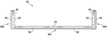
이제, 도 2 내지 도 4를 참조하면, 개별 모듈식 횡방향 비계 유닛, 구체적으로 전술된 개별 모듈식 횡방향 비계 유닛(44)의 상이한 3가지의 도면이 도시되며, 여기서 이 특정 비계 유닛은 길이 신장식 복수의 비계 유닛 조립체의 일부로서 그리고 프레임 측면(22a)에 부착된 상태로부터 제거된 상태로 도면에 도시된다. 이 조건에서, 유닛(44)은 적합하고 안전한 작업자 보조를 위해 이용될 수 있도록 본 발명에 따라 구성된 개별 비계 유닛이 가질 수 있는 구성으로 도시된다.Referring now to Figures 2-4, there are shown three different views of the individual modular transverse scaffolding unit, specifically the individual modular
개별 비계 유닛의 정확한 구성은 구체적으로 본 발명의 임의의 부분이 아니며, 적합한 단일 비계 유닛이 다양한 방식으로 구성될 수 있다. 도 1이 시스템에서 도시된 조립체 내에 도시된 다른 개별 비계 유닛을 나타내는 비계 유닛(44)은 구성이 상당히 단순하다. 이는 복수의 구조물(54, 56, 58, 60)과 같은 하위프레임의 주연부, 작업자-안전 가드-레일 구조물의 3개의 "비-프레임-인접" 측면(44b, 44c, 44d)(특히 도 3에 도시됨)을 따라 그리고 이 하위프레임의 상부에서 그리고 적합한 평면형 직사각형 작업자 플랫폼을 지지하기 위하여 다소 U-형 하위프레임(52)(특히 도 3 참조)을 포함한다. 전술된 바와 같이, 도 2 내지 도 4에서, 비계 유닛(44)은 프레임 구조물(22)로부터 제거되고, 즉 이에 대해 고립된 것으로 도시되며, 단일의 프레임-부착가능 비계 유닛으로 사용되는 경우의 상태가 도시된다. 이 상태에서, 비계 유닛(44)은 이의 마주보는 단부에 대략 2개의 가이드 레일 구조물(54, 60)이 장착되며, 이 상태에서 이는 인접한 개별 유닛(46)의 인접한 결합 단부가 도 1에 도시되는 바와 같이 바로 인접한 다른 개별 유닛 내에서 결합 단부에 바로 인접하게 배열되는 복수의 비계 유닛의 조립체 내에서 구조화된다.The exact configuration of the individual scaffolding units is not specifically an optional part of the present invention, and a suitable single scaffolding unit may be configured in a variety of ways. The
비계 유닛(44)의 각각의 마주보는 단부에 인접하게 하위프레임(52)의 단부 부분에는 하향 연장된 중력 후크 구조물(64)이 고정되고, 플레이트 구조물은 이의 하부 단부에 포획 구조물의 전술된 공통 열들 중 하나의 열 내에서 중력-연결 접근 부위(48)에 배열된 칼럼-고정 중력 포획 구조물에 분리가능하고, 신속하며 선택적으로 연결가능한(후술됨) 개방 하향 U-형 중력 후크(64a)(도 4 참조)를 포함한다. 각각의 후크(64a) 위에는 프레임의 측면으로부터 우연한 분리에 대해 일시적으로 유닛(44)을 고정하기 위한 중력 포획 구조물 내에서 관통보어의 정합에 대해 사용될 수 있는 관통보어(64b)(또한, 특히 도 4 참조)가 제공된다.Adjacent to each opposing end of the
도 2 내지 도 4 및 추가로 각각의 연계된 중력 후크 구조물(64) 및 유닛(44)에 대한 안티-슬로핑(외측의 하향) 안정화 구조물로서 시스템(20) 내에 포함된 개별 비계 유닛(44)과의 작동을 도시하는 설명을 참조하면, 유닛 하위프레임(52)의 연계된 단부 부분에 적절히 결합된 프레임 구조물에 유닛의 단순하고 제거가능한 중력 부착을 허용하는 중요한 기여자로서 안정화 칼럼-결합 베어링 풋(70)이 있는 하부 단부를 갖는 브레이스(66)로 하향 연장 레그(68)에 의해 지지된 신장된 하형 연장 각 브레이스(66)가 제공된다.
유닛(44)과 같은 비계 유닛이 프레임 측면(22a)과 같은 프레임의 측면에 적절히 부착될 때, 이용된 연결 중력 후크 및 포획 구조물은 유닛을 수직 방향으로 포지티브하게 위치시키고, 베어링 훗은 연계된 프레임 칼럼의 측면과 결합하고, 연계된 각 브레이스 및 레그는 유닛-연계 작업자- 지지 플랫폼의 바람직하지 못한 외향 및 하향 기울기에 대해 유닛을 안정화하기 위하여 베어링 풋과 협력한다.When a scaffolding unit, such as
이 상태는 도 1에 도시되며, 여기서 비계 유닛(44)의 인접한 단부는 이 도면의 관찰자에 더 인접한 것으로 보이며, 각 브레이스(66), 연계된 하향 연장 지지 레그 및 칼럼-결합 지지 풋이 명확히 보인다. 가시 지지 레그 및 풋은 이 도면에서 구체적으로 라벨링되지 않고, 이는 도면에서 적합한 도면부호를 삽입하기가 곤란하기 때문이다.This state is shown in Figure 1, where the adjacent end of the
도 2에서, 길이 치수(L)가 도시되고, 이는 개별 비계 유닛의 전체 길이와 거의 동일한 치수인 것으로 전술된 길이 치수이다. 길이 치수(L)는 프레임(22) 내에서 한 쌍의 인접한 칼럼들 사이의 축방향-중심선-축방향-중심선 간격과 실질적으로 정확히 동일하고 이와 모듈식으로 연계된 치수이다. 치수(L)는 또한 도 2에 도시된 2개의 중력 후크 구조물(64)들 사이의 중심-평면-대-중심-평면 거리와 실질적으로 정확히 동일하다. 추가로, 이 치수(L)는 시스템 중력 포획 구조물 내에 제공된 접근 개구들 간의 중심-평면-대-중심 평면 간격과 본 명세서에서 기재된 바와 같이 동일하며, 이에 따라 후크 구조물(64)과 같은 중력 후크 구조물의 중력 포획 구조물 상에서 정밀한 설치가 가능하다.In Fig. 2 a length dimension L is shown, which is the length dimension described above as being approximately equal to the overall length of the individual scaffolding units. The length dimension L is a dimension substantially exactly equal to and modularly associated with the axial-centerline-axial-centerline spacing between a pair of adjacent columns within the
도 5 내지 도 8은 모듈식 횡방향 비계 유닛 조립체, 및 구체적으로는 전술된 개별 비계 유닛(44, 46)을 포함한 2-유닛 조립체를 도시한다. 각각의 2개의 내부-결합된 비계 유닛 내의 특정 구성요소는 개별 유닛(44)에 대해 전술된 이들 구성요소와 동일하며, 각각의 동일한 도면부호가 이들 도면에서 이용된다.5 to 8 show a modular transverse scaffolding unit assembly, and specifically a two-unit assembly comprising the
여기서, 구체적으로 도시된 2-유닛 조립체에 관해, 전체 조립체의 마주보는 단부에는 단부-배열된 가드-레일 구조물(54, 60)이 제공되며, 비 유사 가드-레일 구조물이 2개의 유닛의 내부 결합자의 중심 선을 따라 제공된다. 게다가, 이들 2개의 내부 결합 유닛은 이 유닛이 만나는 이의 인접한 단부에서 전술된 구성요소(64, 66, 68, 70)의 공유 하위조립체가 부착된 공유 하위프레임 구성요소(74)를 포함한 공유 구조적 조립체(72)를 통하여 결합되고, 여기서 구성요소(64)는 공유 중력 후크 구조물이다.Here, with respect to the specifically illustrated two-unit assembly, end-arranged guard-
이제, 도 9 및 도 10을 참조하면, 도 9, 프레임(22) 내의 파이프- 지지 높이(30)의 측면도는 프레임 측면(22a)에 대해 신장된 비계 조립체(42)의 제거가능 부착부와 연계된 2개의 인접한 중력-연결 중력 후크 및 중력 포획 구조물의 상세도를 도시한다. 구체적으로, 이 도면은 조립체(42) 내에서 개별 비계 유닛(44)의 근접 단부에 인접한 도 1의 시야로부터 나타내진 일점쇄선(50)을 따라 정렬된 중력 포획 부위의 공통 열을 따라 취해진 도면이다. 도 9는 2개의 중력 후크 및 중력 포획 구조물을 도시하며, 작은 단편의 중심 개구가 2-구조적-배열-연결 도면을 나타내도록 이 도면에 도시된다.Referring now to Figures 9 and 10, a side view of the pipe-
도면부호(48)는 본 발명의 중력 포획 구조물을 기재하며, 이 도면부호는 도 9 및 도 10에 도시된다. 각각의 중력 포획 구조물(48)은 도 9 및 도 10에서 도면부호(64)로 도시된 중력 후크 구조물과 같이, 평면형 중력 후크 구조물을 수용하기 위하여 일반적으로 평면형 수직 공간(76)을 형성하는 이격되고 평행한 앵글-철 부분(구체적으로 도면부호가 제공되지 않음)과 브래킷의 스타일을 형성하는 도 10에서의 한 쌍의 앵글-철 부재의 형태를 갖는다.
각각의 중력 포획 구조물 매네서, 공간(76)의 하부 단부는 도 9에서 도면부호(78)로 도시된 핀과 같은 중력 포획 핀에 의해 브리지되며(bridge), 각각의 포획 구조물 내에서 이들 핀 각각 위에는 2쌍의 수평 정렬 관통보어가 제공된다(볼트 헤드 뒤에 배열되고 숨겨지며 구체적으로 도면부호가 제공되지 않음). 이들 포획-구조물 관통 보어는 도면부호(80)로 도시된 2개의 이러한 조립체와 같은 너트-볼트 조립체를 수용하기 위해 제공되며, 전술되고 정합되게 배열된 관통보어를 통하여 추가로 통과하는 볼트의 생크가 연계된 중력 포획 구조물에 대해 제 위치에 수용된 중력 후크 구조물을 고정하기 위해 중력 후크 구조물 내에 제공된다.Each gravity trapping structure manesse, the lower end of the
도 9 및 도 10에 도시된 바와 같이, 중력 포획 및 중력 후크 구조물은 연계된 중력 포획 구조물의 중력 포획 핀에 걸쳐 하향 중력에 의해 안착된 각각의 중력 후크 구조물 내에서 중력 후크(64a)와 적절히 결합된 것으로 도시된다. 9 and 10, the gravity trapping and gravity hook structures are properly engaged with the
본 발명의 시스템 내에서 횡방향-비계-구조물 제거가능 설비에 관하여, 개별 비계 유닛 또는 복수의 이러한 유닛의 조립체를 프레임의 측면, 예컨대 프레임 측면(22a)에 제거가능하게 부착할 때, 선택된 비계 구조물, 개별 유닛 또는 복수의 유닛은 당해 프레임의 측면을 향하여 픽업되고 이동되어 조종되고, 이에 다라 이의 연계된 중력 후크 구조물이 프레임 내에서 선택된 높이에서 프레임-고정 중력 포획 구조물과 결합하여 신중하게 하강 및 분리되고, 이에 따라, 하부에 놓인 각 브레이스 및 베어링 풋은 연계된 칼럼의 측면과 공동으로 협력하여 결합되어 설치된 비계 구조물이 안정화된다.With respect to the transverse-scaffold-structure removable installation within the system of the invention, the scaffolding structure selected when removably attaching an individual scaffolding unit or assembly of a plurality of such units to the side of the frame, such as the
이러한 초기 제거가능하게 설치된 비계 구조물의 임시 고정은 그 뒤에 전술된 바와 같이 적합한 너트-볼트 조립체의 설치를 통하여 수행될 수 있다.Temporary fixation of this initially removable scaffolding structure can then be carried out through the installation of a suitable nut-bolt assembly as described above.
미리 설치된 비계 구조물을 제거할 때, 전술된 바와 같이 제거가능 부착 단계가 효과적으로 역전된다.When removing the pre-installed scaffolding structure, the removable attachment step is effectively reversed as described above.
이제 도 11을 참조하면, 매우 단순한 형태의 도면부호(82)는 일반적으로 도면부호(88, 90, 92, 94)로 지정된 4가지의 파이프- 지지 높이를 포함하고, 도면부호(86)로 도시된 빔에 의해 상호연결된 칼럼(84)을 포함하는 신장된 파이프- 지지 프레임의 측면이다.Referring now to Fig. 11, a very
도 11에 도시된 프레임 측면 내에서 칼럼(84)을 따라 그리고 이 상의 상이한 위치에 있는 크고 어두운 점은 프레임(82)의 측면 상에서 그리고 이와 연계된 중력 포획 구조물의 존재를 나타낸다. 또 다른 독립적인 "점 패턴"은 예를 들어, 프레임(82)의 마주보는 측면과 연계될 수 있다. 중력 포획 구조물의 존재를 나타내는 이들 도시된 점에 관하여, 이들 중력-포획 구조물 점은 포획 구조물의 4개의 상이한 공통 열을 따라 정렬되고, 이 열은 일점쇄선(96, 98, 100, 102)으로 도시된다. The large, dark spots at different locations along and above the
이들 공통 포획 구조물 열은 파이프- 지지 높이(88, 90, 92, 94)에 대해 선택적으로, 수직 방향으로 분균일하게 변화하고, 의도적으로 도시된 불균일성은 쉽사리 이용가능한 횡방향-비계 설비에 관해 구현될 수 있는 본 발명의 시스템의 의해 제공된 다능성(versatility)을 강조하기 위함이다.These common capture structure rows vary uniformly in the vertical direction, selectively with respect to the pipe-support heights (88, 90, 92, 94), and intentionally illustrated non-uniformities are realized in terms of readily available transverse-scaffolding installations. It is intended to highlight the versatility provided by the system of the present invention that can be achieved.
길지만 상이한 길이의 점선(104, 106, 108)은 프레임(82)에 대해 상이한 높이에서 부착된 상이한 길이의 비계 구조물을 나타낸다. 비계 구조물(104)은 단일-유닛 구조물, 비계 구조물(106), 신장된 길이의 3-비계-유닛 구조물 및 부정 길이의 복수의 비계 유닛 구조물(108)이다. Long but different lengths of dashed
연결 접근 지점의 변형되고 변화하는 수직 배치와 연계된 추가 사상은 원하는 중력 포획 연결 부위를 형성하기 위하여 핀 또는 볼트 생크가 삽입될 수 있는 수평 정렬 관통보어의 수직 분포를 포함한, 전술된 포획 구조물(48)을 형성하는 쌍을 이루는 앵글-철 부재와 같이 이들 칼럼 및 빔, 신장된 수직 배열 앵글-철 브래킷 구조물들 간의 수직방향으로 이격된 주 모멘트 연결부들 중간의 칼럼의 외측 측면에 수직 방향으로의 부착을 고려한다. 이러한 변형에 관하여, 각 브레이스 및 베어링-풋 구조물의 적합한 재구성화는 하부에 놓인 앵글-철 브래킷 구조물에 관해 구성된다.Additional events associated with the deformed and varying vertical arrangement of the connection access points include a vertical distribution of horizontally aligned through bores into which pins or bolt shanks can be inserted to form the desired gravity capture connection. ) Vertically spaced main moment connections between these columns and beams, elongated vertically arranged angle-iron bracket structures, such as a pair of angle-iron members forming a ), attached in a vertical direction to the outer side of the column in the middle Consider. With respect to this variant, a suitable reconfiguration of each brace and bearing-foot structure is constructed with respect to the underlying angle-iron bracket structure.
고-유용성 모듈식이며, 매우 편리한 시스템이 필수적이며 용이한 파이프-프레임 부착, 작업자- 지지 비계 구조물이 도시되며, 이는 안정적인 프레임-측면 플랫폼에 따라 프레임 내에서 상이한 수평-빔 파이프- 지지 높이에서 지지되는 신장 파이프의 설치, 작업 등을 위해 파이프 프레임의 내측에 작업자가 접근하도록 허용한다.A highly useful modular, very convenient system is essential and easy pipe-frame attachment, operator-supporting scaffolding structures are shown, which are supported at different horizontal-beam pipe-support heights within the frame depending on the stable frame-side platform. Allows the operator to access the inside of the pipe frame for installation, work, etc. of the extension pipe.
파이프- 지지 프레임 내에서 인접한 칼럼들 사이의 중심선-대-중심선 횡방향 간격과 각각 모듈식으로 정합되는 길이를 갖는 신장된 개별 비계 유닛에 따라 형성된, 시스템 내의 제안되고 신속 및 제거가능한 중력-연결가능 비계 구조물의 모듈 속성이 제공되며, 이러한 유닛은 파이프- 지지 프레임 구조물의 상이한 측면을 따라 필요 사에 사용하기 위한 상이한 연장 길이를 갖도록 서로 내부에서 쉽사리 연결될 수 있고, 더 이상 필요치 않을 때 후속 비-손상 제거 및 작업자의 사용 중에 매우 신속한 설치를 허용하는 방식으로 이 시스템이 매우 다양한 파이프- 지지 프레임 구조물 내에서 쉽사리 이용될 수 있다.Proposed, quick and removable gravity-connectable within the system, formed according to elongated individual scaffolding units each having a length that is modularly matched and centerline-to-centerline transverse spacing between adjacent columns within a pipe-support frame The modular properties of the scaffolding structure are provided, and these units can be easily connected inside each other along different sides of the pipe-supporting frame structure to have different extension lengths for use on demand, and subsequent non-damaging when no longer needed. The system can easily be used within a wide variety of pipe-supporting frame structures in a way that allows very quick installation during removal and operator use.
본 발명에 따라 제공된 모듈식 횡방향 비계 지지부의 전술된 아웃트리거 속성은 종래 기술과 구별되는 특징들 중 하나이다.The aforementioned outrigger property of the modular transverse scaffold support provided in accordance with the present invention is one of the features that distinguishes it from the prior art.
선호되는 실시 형태 및 특정 변형이 본 명세서에 기재 및 도시될지라도, 본 발명의 범위 및 사상으로부터 벗어나지 않고 다른 변형 및 변경이 가능하다.Although preferred embodiments and specific modifications are described and illustrated herein, other modifications and changes are possible without departing from the scope and spirit of the present invention.
Claims (23)
상기 제 1 세트의 칼럼을 제 2 세트의 칼럼에 연결하는 복수의 크로스 빔, 상기 복수의 크로스 빔은 상기 프레임 구조물의 제 1 및 제 2 측면 사이의 상이한 높이에서 복수의 파이프 지지 레벨을 형성하고,
프레임 구조물이 지지되고 고정되는 복수의 받침대로서, 각각의 받침대는 실질적으로 콘크리트로 형성되고, 각 받침대는 콘크리트 베이스를 가지며, 콘크리트 베이스의 하부 섹션은 지면 아래에 있고 콘크리트 베이스의 상부 섹션은 시스템이 조립될 때 지면 위에 있으며,
제 1 세트의 칼럼의 각각의 칼럼은 상기 칼럼의 외부 평면 상에 수직으로 분포된 복수의 사전 설치된 중력 포획 구조물을 가지며, 복수의 사전 설치된 중력 포획 구조물 중 하나 이상은 프레임 구조에서 복수의 모든 크로스 빔으로부터 상이한 레벨이 위치되며, 및
복수의 사전 설치된 중력 포획 구조물 세트를 프레임 구조물의 제 1 측면을 따라 복수의 선택 가능한 높이 및 복수의 선택 가능한 종 방향 위치에 결합시키기 위한 후크 구조를 갖는 아웃트리거 비계 유닛, 및 신장된 한 쌍의 연장된 각도 브레이스, 각각의 브레이스는 원위 단부에 베어링 풋을 가지고, 복수의 사전 설치된 중력 포획 구조물 중 하나에 결합된 후크 구조물 중 하나 아래의 제 1 세트의 칼럼중 한 칼럼의 외부 평면과 결합되도록 구성되며, 상기 아웃트리거 비계 유닛은 또한 플로어 및 하나 이상의 작업자-안전 가드-레일 구조물을 포함하고,
상기 사전 설치된 중력 포획 구조물 세트 각각의 사전 설치된 중력 포획 구조물은 서로 수평으로 정렬되며,
상기 후크 구조물은 사전 설치된 중력 포획 구조물 세트의 대응하는 사전 설치 구조물로 각각의 후크 구조물을 하강시킴으로써 각각의 사전 설치된 중력 포획 구조물 세트와 조립되도록 구성되어, 모든 후크 구조가 동일한 수평선을 따라 배열되며, 및
상기 아웃트리거 비계 유닛은 프레임 구조물에 작동 가능하게 장착되도록 구성되어, 아웃트리거 비계 유닛은 상기 프레임 구조물로부터 모든 위치 지지를 유도하는 것을 특징으로 하는 파이프- 지지 시스템.A frame structure comprising a first set of three or more columns, each column having exactly four vertical planes arranged to provide a rectangular cross section to the column, the vertical plane comprising an outer plane, the first set of The columns are connected by a first set of side beams, a first set of columns and a first set of side beams form a first side of the frame structure, and the frame structure is also connected by a second set of side beams. Comprising a second set of columns, the second set of columns and the second set of side beams collectively forming a second side of the frame structure opposite from the first side of the frame structure, and the first and second The side beams of the set each contain an I-beam,
A plurality of cross beams connecting the first set of columns to the second set of columns, the plurality of cross beams forming a plurality of pipe support levels at different heights between the first and second sides of the frame structure,
A plurality of pedestal on which the frame structure is supported and fixed, each pedestal is formed of substantially concrete, each pedestal has a concrete base, the lower section of the concrete base is below the ground and the upper section of the concrete base is assembled by the system. Is on the ground when
Each column of the first set of columns has a plurality of pre-installed gravity capture structures distributed vertically on the outer plane of the column, and at least one of the plurality of pre-installed gravity capture structures is a plurality of all cross beams in the frame structure. Different levels are located from, and
Outrigger scaffolding unit with hook structure for coupling a plurality of pre-installed sets of gravity capture structures to a plurality of selectable heights and a plurality of selectable longitudinal positions along a first side of the frame structure, and an elongated pair of extensions Angular braces, each brace having a bearing foot at its distal end and configured to engage the outer plane of one of the columns of the first set under one of the hook structures coupled to one of the plurality of pre-installed gravity capture structures , The outrigger scaffolding unit also comprises a floor and one or more worker-safe guard-rail structures,
The pre-installed gravity capture structures of each of the pre-installed gravity capture structures set are horizontally aligned with each other,
The hook structure is configured to be assembled with each set of pre-installed gravity capturing structures by lowering each hook structure to a corresponding pre-installed structure of the set of pre-installed gravity capturing structures, so that all hook structures are arranged along the same horizontal line, and
The outrigger scaffolding unit is configured to be operably mounted to the frame structure, wherein the outrigger scaffolding unit derives all positional support from the frame structure.
상기 제 1 세트의 칼럼을 제 2 세트의 칼럼에 연결하는 복수의 크로스 빔, 상기 복수의 크로스 빔은 상기 프레임 구조물의 제 1 및 제 2 측면 사이의 상이한 높이에서 복수의 파이프 지지 레벨을 형성하고,
프레임 구조물이 지지되는 복수의 받침대로서, 각각의 받침대는 콘크리트 베이스 및 상기 콘크리트 베이스로부터 상향 돌출하는 한세트의 앵커 볼트를 가지며, 상기 프레임 구조물은 상기 앵커 볼트 세트를 통해 받침대에 고정되고, 콘크리트 베이스의 하부 섹션은 지면 아래에 있고 콘크리트 베이스의 상부 섹션은 시스템이 조립될 때 지면 위에 있으며,
제 1 세트의 칼럼의 각각의 칼럼은 상기 칼럼의 외부 평면 상에 수직으로 분포된 복수의 사전 설치된 중력 포획 구조물을 가지며, 복수의 사전 설치된 중력 포획 구조물 중 하나 이상은 프레임 구조에서 복수의 모든 크로스 빔으로부터 상이한 레벨이 위치되며, 및
복수의 사전 설치된 중력 포획 구조물 세트를 프레임 구조물의 제 1 측면을 따라 복수의 선택 가능한 높이 및 복수의 선택 가능한 종 방향 위치에 결합시키기 위한 후크 구조를 갖는 아웃트리거 비계 유닛, 및 신장된 한 쌍의 연장된 각도 브레이스, 각각의 브레이스는 원위 단부에 베어링 풋을 가지고, 복수의 사전 설치된 중력 포획 구조물 중 하나에 결합된 후크 구조물 중 하나 아래의 제 1 세트의 칼럼중 한 칼럼의 외부 평면과 결합되도록 구성되며, 상기 아웃트리거 비계 유닛은 또한 하위 프레임, 플로어 및 하나 이상의 작업자-안전 가드-레일 구조물을 포함하고, 상기 하위 프레임은 장축을 형성하고 상기 장축에 평행하게 놓인 I- 빔 및 상기 장축에 직교하며 하위 브레임의 I- 빔을 따라 서로 이격된 한 쌍의 횡방향 빔을 포함하고, 각 횡방향 빔의 단부에는 후크 구조물 중 하나가 장착되고,
상기 사전 설치된 중력 포획 구조물 세트 각각의 사전 설치된 중력 포획 구조물은 서로 수평으로 정렬되며,
상기 후크 구조물은 사전 설치된 중력 포획 구조물 세트의 대응하는 사전 설치 구조물로 각각의 후크 구조물을 하강시킴으로써 각각의 사전 설치된 중력 포획 구조물 세트와 조립되도록 구성되어, 모든 후크 구조가 동일한 수평선을 따라 배열되며, 및
상기 아웃트리거 비계 유닛은 프레임 구조물에 작동 가능하게 장착되도록 구성되어, 아웃트리거 비계 유닛은 상기 프레임 구조물로부터 모든 위치 지지를 유도하는 것을 특징으로 하는 파이프- 지지 시스템.A frame structure comprising a first set of three or more columns, each column having exactly four vertical planes arranged to provide a rectangular cross section to the column, the vertical plane comprising an outer plane, the first set of The columns are connected by a first set of side beams, a first set of columns and a first set of side beams form a first side of the frame structure, and the frame structure is also connected by a second set of side beams. Comprising a second set of columns, the second set of columns and the second set of side beams collectively forming a second side of the frame structure opposite from the first side of the frame structure, and the first and second The side beams of the set each contain an I-beam,
A plurality of cross beams connecting the first set of columns to the second set of columns, the plurality of cross beams forming a plurality of pipe support levels at different heights between the first and second sides of the frame structure,
As a plurality of pedestal on which the frame structure is supported, each pedestal has a concrete base and a set of anchor bolts protruding upward from the concrete base, and the frame structure is fixed to the pedestal through the anchor bolt set, and the lower portion of the concrete base The section is below the ground and the upper section of the concrete base is above the ground when the system is assembled,
Each column of the first set of columns has a plurality of pre-installed gravity capture structures distributed vertically on the outer plane of the column, and at least one of the plurality of pre-installed gravity capture structures is a plurality of all cross beams in the frame structure. Different levels are located from, and
Outrigger scaffolding unit with hook structure for coupling a plurality of pre-installed sets of gravity capture structures to a plurality of selectable heights and a plurality of selectable longitudinal positions along a first side of the frame structure, and an elongated pair of extensions Angular braces, each brace having a bearing foot at its distal end and configured to engage the outer plane of one of the columns of the first set under one of the hook structures coupled to one of the plurality of pre-installed gravity capture structures , The outrigger scaffolding unit also comprises a lower frame, a floor and one or more operator-safe guard-rail structures, the lower frame forming a long axis and an I-beam lying parallel to the long axis and orthogonal to the long axis and lower It includes a pair of transverse beams spaced from each other along the I-beam of the braim, and at the end of each transverse beam, one of the hook structures is mounted,
The pre-installed gravity capture structures of each of the pre-installed gravity capture structures set are horizontally aligned with each other,
The hook structure is configured to be assembled with each set of pre-installed gravity capturing structures by lowering each hook structure to a corresponding pre-installed structure of the set of pre-installed gravity capturing structures, so that all hook structures are arranged along the same horizontal line, and
The outrigger scaffolding unit is configured to be operably mounted to the frame structure, wherein the outrigger scaffolding unit derives all positional support from the frame structure.
Applications Claiming Priority (3)
| Application Number | Priority Date | Filing Date | Title |
|---|---|---|---|
| US201361755974P | 2013-01-24 | 2013-01-24 | |
| US61/755,974 | 2013-01-24 | ||
| PCT/US2014/012463 WO2014116648A1 (en) | 2013-01-24 | 2014-01-22 | Plural-story, pipe-support frame system with modular, removably attachable, lateral-worker-support scaffolding |
Publications (2)
| Publication Number | Publication Date |
|---|---|
| KR20150135240A KR20150135240A (en) | 2015-12-02 |
| KR102206510B1 true KR102206510B1 (en) | 2021-01-25 |
Family
ID=51206860
Family Applications (1)
| Application Number | Title | Priority Date | Filing Date |
|---|---|---|---|
| KR1020157022743A KR102206510B1 (en) | 2013-01-24 | 2014-01-22 | Plural-story, pipe-support frame system with modular, removably attachable, lateral-worker-support scaffolding |
Country Status (11)
| Country | Link |
|---|---|
| US (1) | US9803380B2 (en) |
| EP (1) | EP2948270A4 (en) |
| JP (1) | JP2016508553A (en) |
| KR (1) | KR102206510B1 (en) |
| CN (1) | CN105102183B (en) |
| AU (1) | AU2014209556A1 (en) |
| BR (1) | BR112015017590B1 (en) |
| CA (1) | CA2899004C (en) |
| MX (1) | MX362564B (en) |
| SA (1) | SA515360808B1 (en) |
| WO (1) | WO2014116648A1 (en) |
Families Citing this family (21)
| Publication number | Priority date | Publication date | Assignee | Title |
|---|---|---|---|---|
| KR20170010744A (en) | 2014-01-13 | 2017-02-01 | 콘스테크, 아이엔씨. | Clasp-and-lug system |
| US9341304B2 (en) * | 2014-03-08 | 2016-05-17 | Pall Corporation | Modular filtration frame assembly |
| US9506266B2 (en) * | 2014-09-11 | 2016-11-29 | Aditazz, Inc. | Concrete deck with lateral force resisting system |
| USD768420S1 (en) | 2015-03-30 | 2016-10-11 | Conxtech, Inc. | Toe kick |
| USD796774S1 (en) | 2015-03-30 | 2017-09-05 | Conxtech, Inc. | Rail pallet |
| USD777947S1 (en) | 2015-03-30 | 2017-01-31 | Conxtech, Inc. | Modular ladder |
| USD768466S1 (en) | 2015-03-30 | 2016-10-11 | Conxtech, Inc. | Rail pocket |
| CN105701282B (en) * | 2016-01-08 | 2019-08-13 | 中建三局第一建设工程有限责任公司 | A kind of precast construction method of the multitube group installation frame based on BIM |
| US20170277814A1 (en) * | 2016-03-22 | 2017-09-28 | Robert J. Simmons | Modular building design and data handling system |
| US10280961B1 (en) * | 2016-03-24 | 2019-05-07 | Clifford Bollman | Three-dimensional positioning and holding module system for modular workstations |
| FR3062444B1 (en) * | 2017-02-02 | 2020-04-03 | Technip France | METAL STRUCTURE FOR SUPPORTING FLUIDIC CONDUITS AND INDUSTRIAL INSTALLATION COMPRISING SUCH A METAL STRUCTURE |
| FI3585954T3 (en) * | 2017-02-24 | 2024-04-29 | Parkd Ltd | Prestressed structural beam and method for erecting a building structure comprising the beam. |
| CN109629457A (en) * | 2017-10-06 | 2019-04-16 | 巴里·沃尔特·杰克逊 | Improved bridge overhanging bracket component |
| US10696232B2 (en) * | 2017-11-16 | 2020-06-30 | Cnh Industrial America Llc | Split deck rail |
| WO2019157393A1 (en) | 2018-02-09 | 2019-08-15 | Conxtech, Inc. | Moment connection component lifting tool assembly |
| US11555317B2 (en) | 2018-02-09 | 2023-01-17 | Conxtech, Inc. | Moment connection component clamping tool |
| WO2021168371A1 (en) * | 2020-02-19 | 2021-08-26 | Conxtech, Inc. | Modular pipe rack system |
| KR102359479B1 (en) * | 2020-05-21 | 2022-02-10 | 삼성중공업 주식회사 | Hull structure for container ship |
| CN112360155A (en) * | 2020-11-23 | 2021-02-12 | 中建三局集团有限公司 | Control method for self-adaptive compensation of supporting axial force in concrete |
| KR102545075B1 (en) | 2021-03-23 | 2023-06-19 | 삼성물산 주식회사 | Vertical pipe module unit transport coupling frame and construction method of vertical pipe using the same |
| CN115158590A (en) * | 2022-08-18 | 2022-10-11 | 上海外高桥造船有限公司 | Sectional support and integrated assembly |
Citations (2)
| Publication number | Priority date | Publication date | Assignee | Title |
|---|---|---|---|---|
| JP2000314234A (en) * | 1999-04-30 | 2000-11-14 | Alinco Inc | Device of mounting cargo receiving stage for single tube scaffolding |
| JP2000345621A (en) * | 1999-06-03 | 2000-12-12 | Hitachi Plant Eng & Constr Co Ltd | Temporarily provided module and module assembly method, and connection metal part |
Family Cites Families (118)
| Publication number | Priority date | Publication date | Assignee | Title |
|---|---|---|---|---|
| US835059A (en) * | 1906-05-25 | 1906-11-06 | George Curley | Scaffold. |
| US925677A (en) | 1908-04-27 | 1909-06-22 | Ralph Roy Belcher | Building and shelving construction. |
| US1110185A (en) | 1913-03-12 | 1914-09-08 | Willlis Brown | Release safety-hook. |
| US1400066A (en) | 1914-07-18 | 1921-12-13 | Huck Adolf | Construction toy set |
| US1285946A (en) * | 1916-08-09 | 1918-11-26 | Samuel S Colt | Scaffold-bracket. |
| US1367044A (en) | 1920-01-03 | 1921-02-01 | Hausler John | Crane-hook |
| US1471094A (en) | 1922-04-10 | 1923-10-16 | Walter R Bloss | Crane hook |
| US1729743A (en) | 1927-05-10 | 1929-10-01 | Jorgensen Aage Kjarsgaard | Library-stack-supporting structure |
| US2008087A (en) | 1932-02-23 | 1935-07-16 | Associated Engineers Company | Metallic structure |
| US2569653A (en) * | 1947-05-26 | 1951-10-02 | Fred R Boedecker | Vertically adjustable scaffold carriage |
| US2673700A (en) | 1951-10-22 | 1954-03-30 | Daniel A Eberhardt | Pallet |
| US2897013A (en) * | 1954-08-30 | 1959-07-28 | Preston P Delp | Knockdown scaffold |
| US2833503A (en) * | 1955-04-18 | 1958-05-06 | Lynn B Harshbarger | Platform support apparatus |
| US3148477A (en) | 1960-02-05 | 1964-09-15 | Irma Fabrikerne As | Building block having flexible ribs to engage a similar block |
| US3071205A (en) * | 1961-05-22 | 1963-01-01 | Bil Jax Inc | Adjustable scaffolding |
| GB1046861A (en) * | 1963-01-17 | 1966-10-26 | Acrow Eng Ltd | Improvements in and relating to scaffolding |
| US3270997A (en) * | 1964-03-19 | 1966-09-06 | Kenneth W Gethmann | Scaffold device |
| US3392801A (en) * | 1964-03-19 | 1968-07-16 | Kenneth W. Gethmann | Scaffold device |
| US3410044A (en) | 1965-07-23 | 1968-11-12 | Contemporary Walls Ltd | Foamed plastic based construction elements |
| US3396499A (en) * | 1965-10-05 | 1968-08-13 | Biffani Raffaele | Structural members for building construction |
| GB1166093A (en) | 1965-12-22 | 1969-10-01 | Chepos Zd Y Chemickeho A Potra | Hydraulic Ingot Stripper |
| US3533592A (en) * | 1967-05-03 | 1970-10-13 | Economy Forms Corp | Shoring structure for concrete forms |
| US3564803A (en) * | 1968-12-06 | 1971-02-23 | Mills Scaffold Co Ltd | Extensible scaffold and other load supporting elements |
| US3829999A (en) * | 1969-06-06 | 1974-08-20 | Dart Ind Inc | Illuminated modular type sign |
| DE1929175A1 (en) * | 1969-06-09 | 1970-12-17 | Rensch Eberhard | Wall, especially partition wall system |
| US3562988A (en) | 1969-06-24 | 1971-02-16 | Lock Block Co Z | Building blocks, bricks, tile, panels and the like |
| US3664011A (en) | 1969-08-08 | 1972-05-23 | Jacques Guillon Designers Inc | Method of making a joinery joint |
| US3685866A (en) * | 1970-04-15 | 1972-08-22 | Wilfrid J Patenaude | Connector for structural steel |
| GB1386966A (en) * | 1971-04-28 | 1975-03-12 | Kwikform Ltd | Supporting structure for shuttering |
| US3684058A (en) * | 1971-05-13 | 1972-08-15 | Ultra Products Inc | Scaffold |
| US3978994A (en) * | 1975-07-07 | 1976-09-07 | Lee C. Moore Corporation | Pipe rack with pivoted fingers |
| US4019298A (en) | 1973-07-18 | 1977-04-26 | Johnson Iv John J | Beam suspension system |
| US3977801A (en) * | 1974-11-22 | 1976-08-31 | Thomas Philip Murphy | Connector for structural members |
| US4059931A (en) | 1976-01-29 | 1977-11-29 | Mongan William T | Building framing system for post-tensioned modular building structures |
| DE2758992A1 (en) | 1977-12-30 | 1979-07-12 | Holzhueter Kg | Anchor bolt for lifting concrete slab - is headed to permit slotted plate of lifting eye to slide underneath |
| CH633648A5 (en) | 1978-08-22 | 1982-12-15 | Sulzer Ag | DEVICE FOR ATTACHING STORAGE BOXES USING THE FUEL ELEMENT BUNDLES TO THE BOTTOM OF A WATER BASIN. |
| US4347028A (en) * | 1979-09-17 | 1982-08-31 | Automatic Pipe Racker, Inc. | Pipe handling apparatus |
| US4360230A (en) | 1980-09-12 | 1982-11-23 | The United States Of America As Represented By The United States Department Of Energy | Self locking coupling mechanism for engaging and moving a load |
| US4372425A (en) * | 1981-01-12 | 1983-02-08 | Michael Murphy | Auxiliary scaffolding attachment |
| US4438607A (en) | 1982-03-29 | 1984-03-27 | A. O. Smith Harvestore Products, Inc. | Method and apparatus for leveling a storage structure |
| US4522001A (en) | 1982-04-01 | 1985-06-11 | Anton Meyer | Set of bricks with plugging connections |
| US4577449A (en) * | 1983-11-16 | 1986-03-25 | Aldo Celli | Prefabricated structural connector for steel-frame buildings |
| US4754712A (en) | 1984-05-17 | 1988-07-05 | Amco Corporation | Adjustable rack of shelves |
| DE3430612A1 (en) | 1984-08-20 | 1986-02-27 | Baierl & Demmelhuber GmbH & Co Akustik & Trockenbau KG, 8121 Pähl | METAL SPACES FROM INDIVIDUAL ELEMENTS FOR BUILDING BUILDINGS |
| US4736554A (en) | 1984-10-22 | 1988-04-12 | Tyler Kent W | Bolt system |
| FR2576981B1 (en) | 1985-01-31 | 1988-02-26 | Europ Agence Spatiale | REMOVABLE CONNECTION DEVICE WITH TETRAEDRE |
| US4852501A (en) | 1986-05-16 | 1989-08-01 | Amco Corporation | Adjustable rack of shelves |
| US4830144A (en) * | 1988-01-25 | 1989-05-16 | Saf-T-Green Manufacturing Corporation | Scaffold |
| US4905436A (en) | 1988-03-28 | 1990-03-06 | Hitachi Metals, Ltd. | Column/beam joint structure |
| US4821844A (en) * | 1988-04-11 | 1989-04-18 | Huffman Cary A | Outrigger for scaffolding |
| CA1310041C (en) * | 1988-06-14 | 1992-11-10 | John C. Preston | Scaffolding |
| US5061111A (en) | 1991-01-02 | 1991-10-29 | Kiyoshi Hosokawa | Metal connector for wooden building and jointing structure of wooden building using the same |
| US5244300A (en) | 1991-02-28 | 1993-09-14 | Lehigh University | Structural connector approximating a cone of elliptical cross-section |
| US5240089A (en) | 1991-07-17 | 1993-08-31 | Speral Aluminum Inc. | Modular scaffolding assembly |
| US5135077A (en) * | 1991-08-12 | 1992-08-04 | Universal Builders Supply, Inc. | Scaffolding system |
| US5289665A (en) * | 1991-09-26 | 1994-03-01 | Higgins Gregory J | Orthogonal framework for modular building systems |
| GB2261650A (en) | 1991-11-21 | 1993-05-26 | Lanesfield Engineering Seals L | Lifting pin |
| US5342138A (en) * | 1991-12-27 | 1994-08-30 | Nitto Mokuzai Sangyo Kabushiki Kaisha | Connectors for structural members |
| JPH0561347U (en) * | 1992-01-30 | 1993-08-13 | ユハラ工業株式会社 | Clamp for scaffolding construction |
| FI923118A0 (en) | 1992-07-07 | 1992-07-07 | Tuomo Juola | Building framework. |
| CA2101577C (en) | 1992-07-31 | 2005-06-07 | Dale L. Taipale | Modular portable stage system |
| US5617931A (en) * | 1994-08-11 | 1997-04-08 | L. E. Zygmun And Company, Inc. | Modular scaffolding system |
| CA2139051A1 (en) | 1994-12-23 | 1996-06-24 | George Pantev | Connecting mechanism for tubular frame elements |
| JPH08326300A (en) * | 1995-05-27 | 1996-12-10 | Daiwa House Ind Co Ltd | Column work temporary floor |
| US5590974A (en) * | 1995-05-30 | 1997-01-07 | Yang; Tian-Show | Assembling connector structure |
| US5615529A (en) * | 1996-03-12 | 1997-04-01 | Johnson; Jan C. | Border blocks for tree and shrub decoration |
| DE19655284B4 (en) * | 1996-08-16 | 2008-01-24 | Peri Gmbh | Dismountable facade scaffolding |
| JP3642653B2 (en) * | 1997-04-09 | 2005-04-27 | アルインコ株式会社 | Temporary construction method for receiving stage for frame scaffolding |
| US6758020B2 (en) | 1997-09-08 | 2004-07-06 | Cercorp Initiatives Incorporated | Flexible interlocking wall system |
| JP3080911B2 (en) * | 1997-09-29 | 2000-08-28 | ゼンテリア株式会社 | Joint method of column and beam in building structure with heavy steel structure |
| US6092347A (en) * | 1998-08-11 | 2000-07-25 | Hou; Chung-Chu | Skeleton of a greenhouse |
| US6082070A (en) * | 1998-10-30 | 2000-07-04 | Jen; Michael T. | Easy-to-assembly patio construction |
| US6390719B1 (en) * | 2000-02-29 | 2002-05-21 | Chun Jin Co., Ltd. | Joint of a supporting frame |
| ES2203270B1 (en) * | 2001-02-14 | 2005-02-16 | Ingenieria De Encofrados Y Servicios, S.L. | PERFECTION IN ANDAMIOS DE FACHADA. |
| DE10108784A1 (en) * | 2001-02-23 | 2002-09-05 | Peri Gmbh | Scaffold with vertical supports and horizontal girders |
| US6651393B2 (en) | 2001-05-15 | 2003-11-25 | Lorwood Properties, Inc. | Construction system for manufactured housing units |
| US6837016B2 (en) | 2001-08-30 | 2005-01-04 | Simmons Robert J | Moment-resistant building frame structure componentry and method |
| NL1019611C2 (en) * | 2001-12-19 | 2003-06-20 | Thiel Van Nv | Device is for positioning of auxiliary floors of scaffolding provided with uprights and horizontal members, floors being fitted on at least part of horizontal members |
| CN2525158Y (en) * | 2001-12-30 | 2002-12-11 | 孙为民 | New lifting integrated scaffold |
| US6802169B2 (en) * | 2002-03-18 | 2004-10-12 | Robert J. Simmons | Building frame structure |
| US20050055969A1 (en) * | 2002-03-18 | 2005-03-17 | Simmons Robert J. | Building frame structure |
| US20030178253A1 (en) * | 2002-03-21 | 2003-09-25 | Tatge Robert J. | Portable aircraft maintenance platform |
| CN100532748C (en) | 2003-05-02 | 2009-08-26 | D·W·鲍威尔 | Method and structure for prefabricating architecture |
| CA2436339A1 (en) * | 2003-07-30 | 2005-01-30 | Aluma Enterprises Inc. | Shoring leg with node connectors |
| WO2005028762A2 (en) * | 2003-09-14 | 2005-03-31 | Simmons Robert J | Rotational method and apparatus for welding beam-mount structure to the side(s) of a column |
| JP4446794B2 (en) | 2004-05-10 | 2010-04-07 | ダイキョーニシカワ株式会社 | Member connection structure |
| US8011150B2 (en) * | 2004-08-30 | 2011-09-06 | Conxtech, Inc. | Modular building roof-rim parapet structure |
| US8191332B1 (en) | 2004-09-25 | 2012-06-05 | American Tower Corporation | Reinforcement system for poles |
| US7082694B2 (en) | 2004-11-12 | 2006-08-01 | Lyman Jr Hugh Marion | Center point locator device |
| AU2005337415B2 (en) * | 2005-10-07 | 2011-08-18 | Marl Technologies Inc. | Apparatus and method for handling pipe sections |
| US7637076B2 (en) * | 2006-03-10 | 2009-12-29 | Vaughn Willaim B | Moment-resistant building column insert system and method |
| US7835810B2 (en) | 2006-04-14 | 2010-11-16 | Genesistp, Inc. | Tools and methods for designing a structure using prefabricated panels |
| US8132774B1 (en) | 2006-04-17 | 2012-03-13 | Douglas Whatcott | Concrete forming screed aids |
| ES2303457B1 (en) | 2006-12-01 | 2009-08-03 | Habidite, S.A. | CONSTRUCTION SYSTEM. |
| US8161698B2 (en) | 2007-02-08 | 2012-04-24 | Anemergonics, Llc | Foundation for monopole wind turbine tower |
| US8056299B2 (en) | 2007-03-12 | 2011-11-15 | Mack Industries, Inc. | Foundation construction for superstructures |
| US7469485B1 (en) | 2007-05-10 | 2008-12-30 | Joab Jay Perdue | Apparatus for replicating quadrilateral shapes |
| CN101680227B (en) * | 2007-05-30 | 2012-09-05 | 康克斯科技公司 | Halo/spider, full-moment, column/beam connection in a building frame |
| US20090052980A1 (en) * | 2007-06-01 | 2009-02-26 | Williams Joe W | Scaffold connection with concave engagement and gravity lock |
| US9523188B2 (en) * | 2007-06-22 | 2016-12-20 | Diversakore Llc | Framing structure |
| US8297887B2 (en) | 2007-10-11 | 2012-10-30 | Ness Inventions, Inc. | Masonry block with leveling pads |
| CN101265748B (en) * | 2008-05-07 | 2011-05-11 | 中国华西企业股份有限公司 | Tools type section steel fastener steel tube outer scaffold |
| US7677522B2 (en) | 2008-05-07 | 2010-03-16 | Bakos Stephen M | Support bracket for a column |
| US8136460B2 (en) | 2008-06-09 | 2012-03-20 | Tait Towers, Inc. | Portable locking support and platform system |
| US8522694B2 (en) | 2008-06-20 | 2013-09-03 | Oria Collapsibles, Llc | Structural supporting pallet construction with improved perimeter impact absorbing capabilities |
| USD611166S1 (en) | 2009-06-19 | 2010-03-02 | Westblock Systems, Inc. | Retaining block |
| JP5594987B2 (en) | 2009-06-24 | 2014-09-24 | 三菱重工業株式会社 | Method for manufacturing concrete mount, concrete mount, and connecting material |
| US8905160B1 (en) * | 2009-09-03 | 2014-12-09 | Astec Industries, Inc. | Drill pipe handling assembly |
| DE102009050139A1 (en) | 2009-10-20 | 2011-04-21 | Carl Stahl Gmbh | Slings and load lifting system for use with such a sling |
| US9009011B2 (en) * | 2009-12-18 | 2015-04-14 | Patco, Inc. | Integrated construction platform |
| US20120292131A1 (en) | 2011-05-20 | 2012-11-22 | Gary Lovas | Scaffold, releasable support and method |
| US8627615B2 (en) | 2012-01-10 | 2014-01-14 | DRF, Inc. | Bracket assembly and forming system for structural foundation footings |
| US8789279B2 (en) * | 2012-02-24 | 2014-07-29 | W. Floyd Samons | Unitary safety scaffolding and method for one individual to install the same |
| US9259639B2 (en) | 2012-06-01 | 2016-02-16 | Tait Towers Manufacturing, LLC | Self-leveling platform system, self-leveling supports, and method of assembling a self-leveling platform system |
| US9109874B2 (en) * | 2012-12-29 | 2015-08-18 | Conxtech, Inc. | Modular, six-axis-adjustable, concrete-pour form-structure system |
| JP2016509643A (en) * | 2013-01-27 | 2016-03-31 | コンクステック,インコーポレーテッド | Dual Function Sequential Task Ear Alignment Picking Stack Alignment Building Material Handling System |
| US9341304B2 (en) * | 2014-03-08 | 2016-05-17 | Pall Corporation | Modular filtration frame assembly |
| US9506266B2 (en) * | 2014-09-11 | 2016-11-29 | Aditazz, Inc. | Concrete deck with lateral force resisting system |
-
2014
- 2014-01-22 WO PCT/US2014/012463 patent/WO2014116648A1/en active Application Filing
- 2014-01-22 KR KR1020157022743A patent/KR102206510B1/en active IP Right Grant
- 2014-01-22 AU AU2014209556A patent/AU2014209556A1/en not_active Abandoned
- 2014-01-22 EP EP14743382.5A patent/EP2948270A4/en not_active Withdrawn
- 2014-01-22 US US14/160,797 patent/US9803380B2/en active Active
- 2014-01-22 MX MX2015009514A patent/MX362564B/en active IP Right Grant
- 2014-01-22 BR BR112015017590-2A patent/BR112015017590B1/en active IP Right Grant
- 2014-01-22 JP JP2015555227A patent/JP2016508553A/en active Pending
- 2014-01-22 CA CA2899004A patent/CA2899004C/en active Active
- 2014-01-22 CN CN201480005940.8A patent/CN105102183B/en active Active
-
2015
- 2015-07-23 SA SA515360808A patent/SA515360808B1/en unknown
Patent Citations (2)
| Publication number | Priority date | Publication date | Assignee | Title |
|---|---|---|---|---|
| JP2000314234A (en) * | 1999-04-30 | 2000-11-14 | Alinco Inc | Device of mounting cargo receiving stage for single tube scaffolding |
| JP2000345621A (en) * | 1999-06-03 | 2000-12-12 | Hitachi Plant Eng & Constr Co Ltd | Temporarily provided module and module assembly method, and connection metal part |
Also Published As
| Publication number | Publication date |
|---|---|
| EP2948270A4 (en) | 2016-08-24 |
| BR112015017590A2 (en) | 2020-02-04 |
| MX2015009514A (en) | 2016-03-04 |
| CN105102183A (en) | 2015-11-25 |
| BR112015017590B1 (en) | 2022-08-16 |
| US20140202795A1 (en) | 2014-07-24 |
| US9803380B2 (en) | 2017-10-31 |
| WO2014116648A1 (en) | 2014-07-31 |
| JP2016508553A (en) | 2016-03-22 |
| EP2948270A1 (en) | 2015-12-02 |
| CA2899004C (en) | 2020-12-15 |
| SA515360808B1 (en) | 2019-07-29 |
| CA2899004A1 (en) | 2014-07-31 |
| CN105102183B (en) | 2018-04-20 |
| MX362564B (en) | 2019-01-25 |
| KR20150135240A (en) | 2015-12-02 |
| AU2014209556A1 (en) | 2015-08-20 |
Similar Documents
| Publication | Publication Date | Title |
|---|---|---|
| KR102206510B1 (en) | Plural-story, pipe-support frame system with modular, removably attachable, lateral-worker-support scaffolding | |
| TWI662176B (en) | Scaffolding | |
| US9546489B2 (en) | Formwork support scaffold structure | |
| CA2880140C (en) | Modular platform | |
| US10604951B2 (en) | Support member for joinable scaffolding planks | |
| US9228398B2 (en) | Telescoping riser skid | |
| US9365998B2 (en) | Elevated equipment assemblies, equipment-supporting platforms, and related methods | |
| US20160115697A1 (en) | Suspended scaffolding structure and connector therefor | |
| KR101968222B1 (en) | Scaffold system for construction | |
| CA2998120A1 (en) | Ladder installation for equipment tower | |
| US3472475A (en) | Bridge overhang bracket | |
| KR101691752B1 (en) | The Boiler Superheater Platforms | |
| US10480687B2 (en) | Pipe racks | |
| JP6355264B2 (en) | Suspended scaffolding, suspension scaffold installation method and suspension bracket | |
| JP6602003B2 (en) | Temporary bicycle parking equipment | |
| JP5644898B2 (en) | Master rope device for temporary scaffolding | |
| JP5745151B1 (en) | Construction work scaffolding and construction work scaffolding and dismantling methods | |
| KR20050009837A (en) | Apparatus for fixing bridge checking device to bridge | |
| CN110249100A (en) | Head for beam engagement | |
| KR830002971A (en) | Support structure of building foam |
Legal Events
| Date | Code | Title | Description |
|---|---|---|---|
| E902 | Notification of reason for refusal | ||
| E701 | Decision to grant or registration of patent right | ||
| GRNT | Written decision to grant |