KR102164361B1 - Unmanned store system - Google Patents
Unmanned store system Download PDFInfo
- Publication number
- KR102164361B1 KR102164361B1 KR1020180169889A KR20180169889A KR102164361B1 KR 102164361 B1 KR102164361 B1 KR 102164361B1 KR 1020180169889 A KR1020180169889 A KR 1020180169889A KR 20180169889 A KR20180169889 A KR 20180169889A KR 102164361 B1 KR102164361 B1 KR 102164361B1
- Authority
- KR
- South Korea
- Prior art keywords
- product
- delivery
- handling device
- unit
- stacker crane
- Prior art date
Links
Images


Classifications
-
- G—PHYSICS
- G06—COMPUTING; CALCULATING OR COUNTING
- G06Q—INFORMATION AND COMMUNICATION TECHNOLOGY [ICT] SPECIALLY ADAPTED FOR ADMINISTRATIVE, COMMERCIAL, FINANCIAL, MANAGERIAL OR SUPERVISORY PURPOSES; SYSTEMS OR METHODS SPECIALLY ADAPTED FOR ADMINISTRATIVE, COMMERCIAL, FINANCIAL, MANAGERIAL OR SUPERVISORY PURPOSES, NOT OTHERWISE PROVIDED FOR
- G06Q10/00—Administration; Management
- G06Q10/08—Logistics, e.g. warehousing, loading or distribution; Inventory or stock management
- G06Q10/087—Inventory or stock management, e.g. order filling, procurement or balancing against orders
-
- B—PERFORMING OPERATIONS; TRANSPORTING
- B25—HAND TOOLS; PORTABLE POWER-DRIVEN TOOLS; MANIPULATORS
- B25J—MANIPULATORS; CHAMBERS PROVIDED WITH MANIPULATION DEVICES
- B25J15/00—Gripping heads and other end effectors
- B25J15/0014—Gripping heads and other end effectors having fork, comb or plate shaped means for engaging the lower surface on a object to be transported
-
- B—PERFORMING OPERATIONS; TRANSPORTING
- B66—HOISTING; LIFTING; HAULING
- B66F—HOISTING, LIFTING, HAULING OR PUSHING, NOT OTHERWISE PROVIDED FOR, e.g. DEVICES WHICH APPLY A LIFTING OR PUSHING FORCE DIRECTLY TO THE SURFACE OF A LOAD
- B66F9/00—Devices for lifting or lowering bulky or heavy goods for loading or unloading purposes
- B66F9/06—Devices for lifting or lowering bulky or heavy goods for loading or unloading purposes movable, with their loads, on wheels or the like, e.g. fork-lift trucks
- B66F9/07—Floor-to-roof stacking devices, e.g. "stacker cranes", "retrievers"
-
- B—PERFORMING OPERATIONS; TRANSPORTING
- B66—HOISTING; LIFTING; HAULING
- B66F—HOISTING, LIFTING, HAULING OR PUSHING, NOT OTHERWISE PROVIDED FOR, e.g. DEVICES WHICH APPLY A LIFTING OR PUSHING FORCE DIRECTLY TO THE SURFACE OF A LOAD
- B66F9/00—Devices for lifting or lowering bulky or heavy goods for loading or unloading purposes
- B66F9/06—Devices for lifting or lowering bulky or heavy goods for loading or unloading purposes movable, with their loads, on wheels or the like, e.g. fork-lift trucks
- B66F9/075—Constructional features or details
- B66F9/12—Platforms; Forks; Other load supporting or gripping members
-
- G—PHYSICS
- G06—COMPUTING; CALCULATING OR COUNTING
- G06Q—INFORMATION AND COMMUNICATION TECHNOLOGY [ICT] SPECIALLY ADAPTED FOR ADMINISTRATIVE, COMMERCIAL, FINANCIAL, MANAGERIAL OR SUPERVISORY PURPOSES; SYSTEMS OR METHODS SPECIALLY ADAPTED FOR ADMINISTRATIVE, COMMERCIAL, FINANCIAL, MANAGERIAL OR SUPERVISORY PURPOSES, NOT OTHERWISE PROVIDED FOR
- G06Q30/00—Commerce
- G06Q30/06—Buying, selling or leasing transactions
Landscapes
- Engineering & Computer Science (AREA)
- Business, Economics & Management (AREA)
- Transportation (AREA)
- Structural Engineering (AREA)
- Accounting & Taxation (AREA)
- Finance (AREA)
- Mechanical Engineering (AREA)
- Economics (AREA)
- Physics & Mathematics (AREA)
- Geology (AREA)
- Development Economics (AREA)
- Life Sciences & Earth Sciences (AREA)
- Civil Engineering (AREA)
- Theoretical Computer Science (AREA)
- Marketing (AREA)
- General Physics & Mathematics (AREA)
- General Business, Economics & Management (AREA)
- Strategic Management (AREA)
- Entrepreneurship & Innovation (AREA)
- Tourism & Hospitality (AREA)
- Quality & Reliability (AREA)
- Operations Research (AREA)
- Human Resources & Organizations (AREA)
- Robotics (AREA)
- Warehouses Or Storage Devices (AREA)
Abstract
무인 점포 시스템이 개시된다. 본 발명의 일 실시예에 따른 무인 점포 시스템은, 시스템 본체에 마련되며, 상품이 진열 혹은 보관되는 다수의 선반을 구비하는 상품 보관장치; 및 시스템 본체의 일측에 결합되며, 주문 상품이 출고되는 상품 안전 출고장치를 포함하며, 상품 안전 출고장치는, 상품이 출고되는 출고부를 구비하는 출고장치 캐비닛; 출고부에 이웃된 출고장치 캐비닛의 일측에 마련되며, 주문 상품의 영수증에 프린트되는 바코드를 인식하는 출고측 바코드 스캐너; 및 출고부의 입구 영역에 개폐 가능하게 결합되며, 주문 상품의 영수증에 프린트되는 바코드가 출고측 바코드 스캐너에 인식될 때, 전동식으로 자동 개방되는 전동식 출고부 개폐 도어를 포함한다.The unmanned store system is started. An unmanned store system according to an embodiment of the present invention includes a product storage device provided in the system body and having a plurality of shelves on which products are displayed or stored; And it is coupled to one side of the system body, including a product safety shipping device for shipping the order product, the product safety shipping device, the shipping device cabinet having a shipping unit through which the product is shipped; A delivery-side barcode scanner provided on one side of a delivery device cabinet adjacent to the delivery unit and for recognizing a barcode printed on a receipt of an ordered product; And an electric delivery unit opening and closing door that is opened and closed to the entrance area of the delivery unit and automatically opens when a barcode printed on the receipt of the ordered product is recognized by the delivery side barcode scanner.
Description
본 발명은, 무인 점포 시스템에 관한 것으로서, 더욱 상세하게는, 주문한 상품을 무인(unmanned)으로 출고하는 일련의 무인 점포 기술에 대한 다양한 솔루션(solution)을 충족시킬 수 있으며, 특히 출고부를 통해 출고 예정인 상품이 도난되거나 뒤바뀌지 않고 안전하게 출고될 수 있는 무인 점포 시스템에 관한 것이다.The present invention relates to an unmanned store system, and more particularly, can satisfy various solutions for a series of unmanned store technologies for unmanned delivery of ordered products, and in particular, to be shipped through the delivery department. It relates to an unmanned store system in which goods can be safely shipped without being stolen or altered.
최근 들어 유통업계를 비롯한 편의점 등에서는 인건비와 운영비 절감을 위해 무인 점포 시스템의 적용이 고려되고 있다.In recent years, the distribution industry and convenience stores are considering the application of an unmanned store system to reduce labor and operating costs.
무인 점포 시스템이란 고객이 원하는 상품을 주문하고 결제하면 별도의 로봇(robot)이 무인(unmanned)으로 작동되어 해당 상품을 출고하는 일련의 장치 혹은 시스템을 가리킨다.The unmanned store system refers to a series of devices or systems that when a customer orders and pays for a desired product, a separate robot is operated unmanned to release the product.
자동화 설비 형태인 무인 점포 시스템은 저비용 및 고효율성 그리고 다양한 운영방식의 효과를 제공할 수 있다. 따라서 무인 점포 시스템의 보급이 점차 확산될 수 있을 것이라 예상된다.The unmanned store system, which is an automated facility type, can provide the effects of low cost, high efficiency, and various operating methods. Therefore, it is expected that the spread of unmanned store systems can gradually spread.
한편, 현존하는 무인 점포 시스템은 시중에서 흔히 접할 수 있는 소규모의 자판기 형태에 불과한데, 이와 같은 시스템으로는 무인 점포 기술의 다양한 솔루션(solution)을 충족시킬 수 없다.On the other hand, the existing unmanned store system is only a small vending machine type that is commonly encountered in the market, and such a system cannot satisfy various solutions of unmanned store technology.
특히, 현존하는 자판기 형태의 무인 점포 장치나 혹은 개발 예정에 있는 무인 점포 시스템의 경우, 항상 개방되어 있는 출고부의 상품을 단순히 꺼내는 방식이라서 출고부를 통해 출고 예정인 상품에 대한 처리방안, 예컨대 상품이 도난되거나 여러 손님의 상품이 뒤바뀌는 등의 처리방안이 전혀 마련되어 있지 않다는 점을 두루 고려해볼 때, 이를 해결하기 위한 신개념의 무인 점포 시스템에 대한 필요성이 대두된다.In particular, in the case of an existing vending machine-type unmanned store system or an unmanned store system that is expected to be developed, it is a method of simply taking out products from the always open shipping department. Considering the fact that there are no measures to deal with, such as changing products of various customers, the need for a new concept unmanned store system to solve this problem emerges.
따라서 본 발명이 이루고자 하는 기술적 과제는, 주문한 상품을 무인(unmanned)으로 출고하는 일련의 무인 점포 기술에 대한 다양한 솔루션(solution)을 충족시킬 수 있으며, 특히 출고부를 통해 출고 예정인 상품이 도난되거나 뒤바뀌지 않고 안전하게 출고될 수 있는 무인 점포 시스템을 제공하는 것이다.Therefore, the technical problem to be achieved by the present invention is that it is possible to meet various solutions for a series of unmanned store technologies that release ordered products unmanned, and in particular, products scheduled to be shipped through the delivery department are not stolen or replaced. It is to provide an unmanned store system that can be safely shipped without.
본 발명의 일 측면에 따르면, 시스템 본체에 마련되며, 상품이 진열 혹은 보관되는 다수의 선반을 구비하는 상품 보관장치; 및 상기 시스템 본체의 일측에 결합되며, 주문 상품이 출고되는 상품 안전 출고장치를 포함하며, 상기 상품 안전 출고장치는, 상품이 출고되는 출고부를 구비하는 출고장치 캐비닛; 상기 출고부에 이웃된 상기 출고장치 캐비닛의 일측에 마련되며, 주문 상품의 영수증에 프린트되는 바코드를 인식하는 출고측 바코드 스캐너; 및 상기 출고부의 입구 영역에 개폐 가능하게 결합되며, 상기 주문 상품의 영수증에 프린트되는 바코드가 상기 출고측 바코드 스캐너에 인식될 때, 전동식으로 자동 개방되는 전동식 출고부 개폐 도어를 포함하는 것을 특징으로 하는 무인 점포 시스템이 제공될 수 있다.According to an aspect of the present invention, a product storage device provided in a system main body and having a plurality of shelves for displaying or storing products; And a product safety delivery device coupled to one side of the system main body and through which an ordered product is shipped, wherein the product safety delivery device includes: a delivery device cabinet including a delivery unit through which products are delivered; A delivery-side barcode scanner provided on one side of the delivery device cabinet adjacent to the delivery unit and for recognizing a barcode printed on a receipt of an ordered product; And an electric delivery unit opening/closing door that is opened and closed to the entrance area of the delivery unit and automatically opened when the barcode printed on the receipt of the ordered product is recognized by the delivery barcode scanner. An unmanned store system can be provided.
상기 상품 안전 출고장치는, 상기 출고부의 입구 영역에 마련되며, 상기 출고부의 입구에 물체가 배치될 때, 상기 전동식 출고부 개폐 도어가 개방된 상태를 유지하도록 신호를 전송하는 제1 에어리어 센서(AREA SENSOR)를 더 포함할 수 있다.The product safety delivery device is provided in the entrance area of the delivery unit, and when an object is placed at the entrance of the delivery unit, a first area sensor (AREA) that transmits a signal to keep the electric delivery unit opening/closing door open. SENSOR) may be further included.
상기 상품 안전 출고장치는, 주문 상품이 배출될 수 있도록 상기 출고장치 캐비닛의 배면에 형성되는 상품 배출구에 개폐 가능하게 마련되는 상품 배출용 도어; 및 상기 출고장치 캐비닛 내에서 상기 상품 배출구에 경사지게 연결되며, 배출되는 상품을 상기 출고부로 가이드하는 슬라이드 슈트를 더 포함할 수 있다.The product safety delivery device includes: a product discharge door provided to be opened and closed at a product discharge port formed on a rear surface of the delivery device cabinet so that ordered products can be discharged; And a slide chute connected inclined to the product outlet in the delivery device cabinet and guiding the discharged product to the delivery unit.
상기 상품 안전 출고장치는, 상기 출고부 내에 마련되되 상기 슬라이드 슈트에 가이드되어 낙하되는 상품을 지지하며, 해당 위치에서 업/다운(up/down) 이동 가능하게 마련되는 업/다운식 상품 지지대를 더 포함할 수 있다.The product safety delivery device further includes an up/down product support provided in the delivery unit to support the product falling by being guided by the slide chute, and to move up/down at a corresponding position. Can include.
상기 상품 안전 출고장치는, 상기 슬라이드 슈트의 주변에 배치되며, 상품을 감지하는 제2 에어리어 센서; 및 상기 출고부 내의 하부 영역에 마련되며, 상기 출고부 내에 상품이 있는지의 여부를 감지하는 제3 에어리어 센서를 더 포함할 수 있다.The product safety delivery device may include a second area sensor disposed around the slide chute and detecting a product; And a third area sensor provided in a lower area within the delivery unit and detecting whether or not there is a product in the delivery unit.
상기 상품 안전 출고장치는, 상기 출고장치 캐비닛 내에서 상기 출고부의 하부를 형성하되 출고되지 않는 상품이 보관되는 비출고 상품 보관부를 더 포함할 수 있다.The product safety delivery device may further include a non-release product storage unit that forms a lower portion of the delivery unit in the delivery device cabinet, but stores products that are not released.
상기 상품 안전 출고장치는, 상기 비출고 상품 보관부와 선택적으로 연통 가능하게 상기 비출고 상품 보관부의 바닥에 마련되는 바닥 개폐 도어를 더 포함할 수 있다.The product safety delivery device may further include a floor opening and closing door provided on the bottom of the non-delivery product storage unit to selectively communicate with the non-delivery product storage unit.
상기 상품 안전 출고장치는, 상기 출고측 바코드 스캐너에 이웃된 상기 출고장치 캐비닛의 전면 상부에 배치되며, 출고현황을 표시하는 출고측 터치 모니터; 및 상기 출고측 터치 모니터의 일측에 점멸 가능하게 마련되는 출고측 램프를 더 포함할 수 있다.The product safety delivery device includes: a delivery-side touch monitor disposed on a front upper side of the delivery device cabinet adjacent to the delivery-side barcode scanner, and displaying a delivery status; And it may further include a factory-side lamp provided to be flashing on one side of the factory-side touch monitor.
상기 상품 보관장치의 일측에 이동 가능하게 배치되며, 상기 선반으로 상품을 입고하거나 상기 선반으로부터 상품을 출고하는 적어도 하나의 스태커 크레인(Stacker Crane); 및 상기 스태커 크레인에 연결되고 상기 스태커 크레인과 상호작용하며, 상품의 핸들링을 위하여 상품을 그립핑(gripping)하는 상품 핸들링장치를 더 포함할 수 있다.At least one stacker crane, which is movably disposed on one side of the product storage device, and stores goods on the shelf or discharges products from the shelf; And a product handling device connected to the stacker crane, interacting with the stacker crane, and gripping a product for handling the product.
상기 상품 핸들링장치는, 핸들링장치 본체; 상기 핸들링장치 본체에 상대회전 가능하게 결합되는 회전 헤드; 및 상기 회전 헤드에 이동 가능하게 결합되며, 상호간 접근 또는 이격되는 동작에 기초하여 상품을 그립핑하는 한 쌍의 그립퍼를 포함할 수 있다.The product handling device includes: a handling device main body; A rotating head coupled to the handling device body to be relatively rotatable; And a pair of grippers that are movably coupled to the rotating head and grip a product based on an approach or spaced apart from each other.
상기 상품 핸들링장치는, 상기 회전 헤드에 결합되며, 상기 한 쌍의 그립퍼를 상호간 접근 또는 이격 구동시키는 그립핑 구동부; 및 상기 그립핑 구동부에 의해 상기 한 쌍의 그립퍼가 이동될 때 상기 한 쌍의 그립퍼의 이동을 가이드하는 제1 LM 가이드를 더 포함할 수 있다.The product handling device may include a gripping driving unit coupled to the rotating head and configured to drive the pair of grippers to approach or separate from each other; And a first LM guide configured to guide the movement of the pair of grippers when the pair of grippers are moved by the gripping driving unit.
상기 상품 핸들링장치는, 상기 회전 헤드에 마련되고 상기 한 쌍의 그립퍼와 연결되며, 상기 한 쌍의 그립퍼를 상기 한 쌍의 그립퍼가 그립핑되는 방향에 교차되는 포킹(forking) 방향으로 구동시키는 포킹 구동부; 및 상기 포킹 구동부에 의해 상기 한 쌍의 그립퍼가 이동될 때 상기 한 쌍의 그립퍼의 이동을 가이드하는 제2 LM 가이드를 더 포함할 수 있다.The product handling device is provided on the rotating head, is connected to the pair of grippers, and drives the pair of grippers in a forking direction crossing a direction in which the pair of grippers are gripped. ; And a second LM guide configured to guide the movement of the pair of grippers when the pair of grippers are moved by the forking driving unit.
상기 상품 핸들링장치는 상기 핸들링장치 본체와 상기 회전 헤드에 연결되며, 상기 핸들링장치 본체를 기준으로 상기 회전 헤드를 회전 구동시키는 헤드 회전 구동부를 더 포함할 수 있으며, 상기 한 쌍의 그립퍼의 마주보는 내벽에는 미끄러짐을 방지하는 미끄러짐 방지 패턴이 표면에 형성되는 미끄러짐 방지 패드가 결합될 수 있다.The product handling device may further include a head rotation driving unit connected to the handling device main body and the rotating head and rotating the rotating head with respect to the handling device main body, and facing inner walls of the pair of grippers There may be a non-slip pad formed on the surface of the non-slip pattern to prevent slipping may be combined.
상기 상품 핸들링장치는, 상기 회전 헤드에서 전후진 이동 가능하게 상기 회전 헤드에 결합되며, 상품을 밀거나 당기는(push & pull) 상품 핸들링 바아; 및 상기 상품 핸들링 바아을 전후진 구동시키는 바아 구동부를 더 포함할 수 있다.The product handling device includes: a product handling bar that is coupled to the rotation head so as to move forward and backward from the rotation head, and pushes and pulls a product; And it may further include a bar driving unit for driving the product handling bar forward and backward.
상기 상품 핸들링 바아의 단부에 흡착부가 결합될 수 있다.An adsorption unit may be coupled to an end of the product handling bar.
상기 상품 핸들링장치는, 상기 회전 헤드의 일측에 결합되는 더미 블록; 및 상기 더미 블록에 결합되며, 소정의 신호에 기초하여 전방을 촬영하는 네트워크 카메라를 더 포함할 수 있다.The product handling device may include a dummy block coupled to one side of the rotating head; And a network camera coupled to the dummy block and photographing a front side based on a predetermined signal.
상기 상품 핸들링장치는, 상기 핸들링장치 본체에 마련되고 상기 스태커 크레인에 연결되며, 상하 방향을 따라 상기 상품 핸들링장치를 업/다운(up/down) 이동시키는 핸들링장치 업/다운 이동부; 및 상기 핸들링장치 본체에 회전 가능하게 마련되며, 상기 상품 핸들링장치가 업/다운(up/down) 이동될 때, 상기 상품 핸들링장치의 이동을 가이드하는 다수의 트랙 롤러를 더 포함할 수 있다.The product handling device includes: a handling device up/down moving part provided in the handling device main body, connected to the stacker crane, and moving the product handling device up/down along a vertical direction; And a plurality of track rollers rotatably provided on the main body of the handling device, and guiding the movement of the product handling device when the product handling device is moved up/down.
상기 시스템 본체 내의 일측에 서보가 마련될 수 있으며, 상품을 재배치하기 위한 상품 재배치모드 입력 시 상기 스태커 크레인 및 상기 상품 핸들링장치의 작용에 의해 상기 선반 상의 상품이 자동으로 재배치될 수 있다.A servo may be provided on one side of the system body, and when a product relocation mode for relocating products is input, the products on the shelf may be automatically relocated by the action of the stacker crane and the product handling device.
상기 시스템 본체 내의 일측에 청소용구 보관부가 마련될 수 있으며, 상기 선반을 청소하기 위한 선반 청소모드 입력 시 상기 스태커 크레인 및 상기 상품 핸들링장치의 작용에 의해 상기 선반의 표면이 상기 청소용구에 의해 자동 청소될 수 있다.A cleaning tool storage unit may be provided on one side of the system main body, and the surface of the shelf is automatically cleaned by the cleaning tool by the action of the stacker crane and the product handling device when entering a shelf cleaning mode for cleaning the shelf. Can be.
소정의 입력신호를 입력하는 입력부; 및 상기 입력부의 입력신호에 기초하여 주문한 상품이 무인(unmanned)으로 출고되도록 상기 스태커 크레인 및 상기 상품 핸들링장치의 동작을 컨트롤하는 컨트롤러를 더 포함하며, 상기 컨트롤러는, 상품을 재배치하기 위한 상품 재배치모드 입력 시 상기 선반 상의 상품이 자동으로 재배치되게 상기 스태커 크레인 및 상기 상품 핸들링장치를 자동으로 컨트롤하고, 상기 선반을 청소하기 위한 선반 청소모드 입력 시 상기 선반의 표면이 상기 청소용구에 의해 자동 청소되게 상기 스태커 크레인 및 상기 상품 핸들링장치를 자동으로 컨트롤할 수 있다.An input unit for inputting a predetermined input signal; And a controller for controlling the operation of the stacker crane and the product handling device so that the ordered product is released unmanned based on the input signal of the input unit, wherein the controller is a product relocation mode for relocating products. Upon input, the stacker crane and the product handling device are automatically controlled so that the product on the shelf is automatically rearranged, and the surface of the shelf is automatically cleaned by the cleaning tool when entering the shelf cleaning mode for cleaning the shelf. The stacker crane and the product handling device can be automatically controlled.
상기 스태커 크레인의 이동을 위하여 상기 스태커 크레인에 폐루프 타입으로 연결되는 폐루프 라인을 구비하며, 상기 폐루프 라인의 회전 동작에 기초한 상기 스태커 크레인의 이동 시 상기 스태커 크레인의 흔들림(Swing)을 저지시키는 크레인 안티 스윙 이동부(Crane Anti Swing Moving Part)를 포함할 수 있다.For the movement of the stacker crane, a closed loop line connected to the stacker crane in a closed loop type is provided, and when the stacker crane moves based on the rotational motion of the closed loop line, the stacker crane is prevented from swinging. It may include a crane anti swing moving part.
상기 크레인 안티 스윙 이동부는, 상기 폐루프 라인의 일단부에 연결되며, 상기 폐루프 라인을 회전시키기 위한 구동력을 발생시키는 라인 구동부; 상기 폐루프 라인의 타단부에 회전 가능하게 연결되되 상기 라인 구동부에 의해 회전되는 상기 폐루프 라인의 타단부를 지지하는 라인 종동부; 상기 라인 구동부와 상기 라인 종동부 사이에서 상기 폐루프 라인과 접하게 배치되며, 상기 폐루프 라인의 회전을 가이드하는 다수의 라인 가이드; 및 상기 폐루프 라인과 클램핑되는 라인 클램프를 포함할 수 있다.The crane anti-swing moving part may include a line driving part connected to one end of the closed loop line and generating a driving force for rotating the closed loop line; A line follower rotatably connected to the other end of the closed loop line and supporting the other end of the closed loop line rotated by the line driver; A plurality of line guides disposed between the line driver and the line follower to contact the closed loop line and guiding the rotation of the closed loop line; And a line clamp clamped with the closed loop line.
상기 폐루프 라인이 타이밍 벨트이며, 상기 라인 구동부는 모터에 의해 구동되는 구동 풀리이며, 상기 라인 종동부 및 상기 라인 가이드는 각각 종동 풀리 및 아이들 풀리일 수 있다.The closed loop line is a timing belt, the line driver is a drive pulley driven by a motor, and the line follower and the line guide may be driven pulleys and idle pulleys, respectively.
본 발명에 따르면, 주문한 상품을 무인(unmanned)으로 출고하는 일련의 무인 점포 기술에 대한 다양한 솔루션(solution)을 충족시킬 수 있으며, 특히 출고부를 통해 출고 예정인 상품이 도난되거나 뒤바뀌지 않고 안전하게 출고될 수 있다.According to the present invention, it is possible to meet various solutions for a series of unmanned store technologies that release ordered products unmanned, and in particular, products scheduled to be shipped through the delivery department can be safely shipped without being stolen or altered. have.
도 1은 본 발명의 일 실시예에 따른 무인 점포 시스템의 사시도이다.
도 2는 도 1의 정면도이다.
도 3은 도 1의 평면도로서 점포에 적용된 상태의 도면이다.
도 4는 도 3의 요부 측면도이다.
도 5는 도 4에서 선반을 제거한 상태의 도면이다.
도 6은 도 4를 개념적으로 도시한 구성도이다.
도 7은 도 4의 사시도이다.
도 8은 도 7의 A 영역의 확대도이다.
도 9는 상품 핸들링장치의 동작도이다.
도 10은 상품 핸들링장치의 사시도이다.
도 11은 도 10의 배면 사시도이다.
도 12는 내지 도 14는 각각 상품 핸들링장치의 움직임을 설명하기 위한 도면들이다.
도 15는 불량상품 수거장치의 구조도이다.
도 16 및 도 17은 도 15의 사용상태도이다.
도 18 내지 도 21은 상품 보관장치의 구조도로서 선반의 높이를 조절하는 과정을 도시한 도면들이다.
도 22는 선반의 간격조절을 설명하기 위한 도면이다.
도 23은 도 22의 정면도이다.
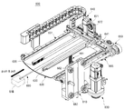
도 24는 상품 안전 출고장치의 사시도이다.
도 25는 도 24의 정면 투영도이다.
도 26은 배출구 영역의 구조도이다.
도 27은 도 24의 사용상태를 설명하기 위한 도면이다.
도 28은 도 27의 확대도로서 상품이 이동되는 과정을 도시한 도면이다.
도 29는 상품정보 관리형 상품 입고장치의 사시도이다.
도 30 내지 도 35는 상품 방향 얼라인유닛의 동작을 단계적으로 도시한 도면들이다.
도 36은 내지 도 38은 본 발명의 일 실시예에 따른 무인 점포 시스템의 상품 재배치 기능을 설명하기 위한 도면들이다.
도 39 내지 도 41은 본 발명의 일 실시예에 따른 무인 점포 시스템의 자동청소 기능을 설명하기 위한 도면들이다.
도 42는 본 발명의 일 실시예에 따른 무인 점포 시스템의 제어블록도이다.1 is a perspective view of an unmanned store system according to an embodiment of the present invention.
2 is a front view of FIG. 1.
FIG. 3 is a plan view of FIG. 1 and is a view applied to a store.
Figure 4 is a side view of the main part of Figure 3;
5 is a view of the shelf removed from FIG. 4.
6 is a configuration diagram conceptually showing FIG. 4.
7 is a perspective view of FIG. 4.
8 is an enlarged view of area A of FIG. 7.
9 is an operation diagram of the product handling device.
10 is a perspective view of a product handling device.
11 is a rear perspective view of FIG. 10.
12 to 14 are diagrams for explaining the movement of the product handling device, respectively.
15 is a structural diagram of an apparatus for collecting defective products.
16 and 17 are diagrams illustrating a use state of FIG. 15.
18 to 21 are diagrams illustrating a process of adjusting the height of a shelf as a structural diagram of a product storage device.
22 is a view for explaining the interval adjustment of the shelf.
23 is a front view of FIG. 22.
24 is a perspective view of a product safety delivery device.
Fig. 25 is a front projection view of Fig. 24;
26 is a structural diagram of an outlet region.
FIG. 27 is a diagram for explaining the use state of FIG. 24;
FIG. 28 is an enlarged view of FIG. 27, illustrating a process of moving a product.
29 is a perspective view of a product information management type product warehousing device.
30 to 35 are diagrams showing the operation of the product direction alignment unit step by step.
36 to 38 are diagrams for explaining a product relocation function of the unmanned store system according to an embodiment of the present invention.
39 to 41 are diagrams for explaining an automatic cleaning function of an unmanned store system according to an embodiment of the present invention.
42 is a control block diagram of an unmanned store system according to an embodiment of the present invention.
본 발명과 본 발명의 동작상의 이점 및 본 발명의 실시에 의하여 달성되는 목적을 충분히 이해하기 위해서는 본 발명의 바람직한 실시예를 예시하는 첨부도면 및 첨부도면에 기재된 내용을 참조하여야만 한다.In order to fully understand the present invention, operational advantages of the present invention, and objects achieved by the implementation of the present invention, reference should be made to the accompanying drawings illustrating preferred embodiments of the present invention and the contents described in the accompanying drawings.
이하, 첨부도면을 참조하여 본 발명의 바람직한 실시예를 설명함으로써, 본 발명을 상세히 설명한다. 각 도면에 제시된 동일한 참조부호는 동일한 부재를 나타낸다.Hereinafter, the present invention will be described in detail by describing a preferred embodiment of the present invention with reference to the accompanying drawings. The same reference numerals in each drawing indicate the same member.
도 1은 본 발명의 일 실시예에 따른 무인 점포 시스템의 사시도이고, 도 2는 도 1의 정면도이며, 도 3은 도 1의 평면도로서 점포에 적용된 상태의 도면이고, 도 4는 도 3의 요부 측면도이며, 도 5는 도 4에서 선반을 제거한 상태의 도면이고, 도 6은 도 4를 개념적으로 도시한 구성도이며, 도 7은 도 4의 사시도이고, 도 8은 도 7의 A 영역의 확대도이며, 도 9는 상품 핸들링장치의 동작도이고, 도 10은 상품 핸들링장치의 사시도이며, 도 11은 도 10의 배면 사시도이고, 도 12는 내지 도 14는 각각 상품 핸들링장치의 움직임을 설명하기 위한 도면들이며, 도 15는 불량상품 수거장치의 구조도이고, 도 16 및 도 17은 도 15의 사용상태도이며, 도 18 내지 도 21은 상품 보관장치의 구조도로서 선반의 높이를 조절하는 과정을 도시한 도면들이고, 도 22는 선반의 간격조절을 설명하기 위한 도면이며, 도 23은 도 22의 정면도이고, 도 24는 상품 안전 출고장치의 사시도이며, 도 25는 도 24의 정면 투영도이고, 도 26은 배출구 영역의 구조도이며, 도 27은 도 24의 사용상태를 설명하기 위한 도면이고, 도 28은 도 27의 확대도로서 상품이 이동되는 과정을 도시한 도면이며, 도 29는 상품정보 관리형 상품 입고장치의 사시도이고, 도 30 내지 도 35는 상품 방향 얼라인유닛의 동작을 단계적으로 도시한 도면들이며, 도 36은 내지 도 38은 본 발명의 일 실시예에 따른 무인 점포 시스템의 상품 재배치 기능을 설명하기 위한 도면들이고, 도 39 내지 도 41은 본 발명의 일 실시예에 따른 무인 점포 시스템의 자동청소 기능을 설명하기 위한 도면들, 그리고 도 42는 본 발명의 일 실시예에 따른 무인 점포 시스템의 제어블록도이다.1 is a perspective view of an unmanned store system according to an embodiment of the present invention, FIG. 2 is a front view of FIG. 1, FIG. 3 is a plan view of FIG. 1 and a view applied to a store, and FIG. 4 is a main part of FIG. It is a side view, FIG. 5 is a view in a state in which the shelf is removed from FIG. 4, FIG. 6 is a schematic diagram of FIG. 4, FIG. 7 is a perspective view of FIG. 4, and FIG. 8 is an enlarged view of area A of FIG. Fig. 9 is an operation diagram of the product handling device, Fig. 10 is a perspective view of the product handling device, Fig. 11 is a rear perspective view of Fig. 10, and Figs. 12 to 14 are respectively explaining the movement of the product handling device 15 is a structural diagram of a defective product collection device, FIGS. 16 and 17 are diagrams of a use state of FIG. 15, and FIGS. 18 to 21 are structural diagrams of a product storage device, illustrating a process of adjusting the height of a shelf. Figures are drawings, Figure 22 is a view for explaining the distance adjustment of the shelf, Figure 23 is a front view of Figure 22, Figure 24 is a perspective view of a product safety shipping device, Figure 25 is a front projection view of Figure 24, Figure 26 is It is a structural diagram of the outlet area, FIG. 27 is a diagram for explaining the use state of FIG. 24, FIG. 28 is an enlarged view of FIG. 27 and a diagram showing a process of moving a product, and FIG. 29 is a product information management type product warehousing A perspective view of the device, FIGS. 30 to 35 are diagrams showing the operation of the product direction alignment unit step by step, and FIGS. 36 to 38 illustrate a product relocation function of the unmanned store system according to an embodiment of the present invention. 39 to 41 are diagrams for explaining an automatic cleaning function of an unmanned store system according to an embodiment of the present invention, and FIG. 42 is a control of an unmanned store system according to an embodiment of the present invention It is a block diagram.
이들 도면을 참조하면, 본 실시예에 따른 무인 점포 시스템은 주문한 상품을 무인(unmanned)으로 출고하는 일련의 무인 점포 기술에 대한 다양한 솔루션(solution)을 충족시킬 수 있으며, 특히 출고부(511, 도 28 참조)를 통해 출고 예정인 상품이 도난되거나 뒤바뀌지 않고 안전하게 출고될 수 있도록 한 것이다.Referring to these drawings, the unmanned store system according to the present embodiment can satisfy various solutions for a series of unmanned store technologies for shipping ordered products unmanned, and in particular, the
이러한 효과를 제공할 수 있는 본 실시예에 따른 무인 점포 시스템은 시스템 본체(100)와, 시스템 본체(100)에 마련되는 상품 안전 출고장치(500)를 포함한다.The unmanned store system according to the present embodiment capable of providing such an effect includes a system
이 외에도 본 실시예에 따른 무인 점포 시스템의 시스템 본체(100)에는 상품 보관장치(200), 불량상품 수거장치(300), 상품정보 관리형 상품 입고장치(400), 상품 핸들링장치(600)가 위치별로 마련되어 해당 기능을 수행한다. 상품 핸들링장치(600)는 스태커 크레인(120, Stacker Crane)에 연결되며, 스태커 크레인(120)과의 상호작용으로 선반으로 상품을 입고하거나 선반으로부터 상품을 출고한다.In addition, the system
각 구성을 살펴보면, 우선 시스템 본체(100)는 본 실시예에 따른 무인 점포 시스템의 외관 구조를 이룬다.Looking at each configuration, first, the system
본 실시예에 따른 무인 점포 시스템을 점포에 설치할 때는 도 3처럼 점포 내의 일측에 시스템 본체(100)을 배치한 후, 상품 보관장치(200), 불량상품 수거장치(300), 상품정보 관리형 상품 입고장치(400), 상품 안전 출고장치(500), 상품 핸들링장치(600)가 연결되는 스태커 크레인(120)을 설치하면 된다.When installing the unmanned store system according to the present embodiment in a store, after arranging the
도 3을 간략하게 살펴보면 사용자, 즉 고객은 출입문(10)을 통해 점포 내로 들어와 무인 점포 시스템을 통해 무인으로 상품을 구매하면 된다. 점포에는 벽체(30)의 일측에 관리자 출입문(20)이 마련되는데, 이곳은 권한을 갖는 관리자만 출입이 허용되는 장소를 이룬다.Referring to FIG. 3 briefly, a user, that is, a customer, enters the store through the
시스템 본체(100)의 일측에는 청소용구 보관부(101)가 마련된다. 청소용구 보관부(101) 내에는 스폰지 등의 청소용구(102)가 마련된다. 그리고 청소용구 보관부(101)의 앞쪽에는 서보(105)가 마련된다.A cleaning
도면에는 도시하지 않았으나 도 3의 점포 일측에 적어도 하나의 키오스크(KIOSK)가 배치될 수 있다. 키오스크(KIOSK)는 터치스크린 방식의 정보전달 시스템으로서 상품을 선택하고 주문하는 역할을 한다. 이러한 키오스크(KIOSK)는 본 실시예에 따른 무인 점포 시스템과 별개로 설치될 수도 있으나 시스템 본체(100)의 일측에 탑재되어도 무방하다. 따라서 이러한 사항 모두가 본 발명의 권리범위에 속한다 하여야 할 것이다.Although not shown in the drawing, at least one kiosk may be disposed on one side of the store of FIG. 3. Kiosk (KIOSK) is a touch screen type information delivery system that selects and orders products. Such a kiosk (KIOSK) may be installed separately from the unmanned store system according to the present embodiment, but may be mounted on one side of the system
상품 보관장치(200)는 도 1, 도 3, 도 4, 도 9, 그리고 도 18 내지 도 23에 도시된 바와 같이, 상품이 보관되는 장소를 이룬다. 편의점을 예로 들면, 과자, 초콜릿, 빵 등의 상품이 상품 보관장치(200)에 위치별로 보관될 수 있다.As shown in FIGS. 1, 3, 4, 9, and 18 to 23, the
상품 보관장치(200)는 캐비닛 구조를 이룰 수 있다. 본 실시예의 경우, 스태커 크레인(120)을 사이에 두고 상품 보관장치(200)가 그 양측에 배치되는 구조를 갖는다. 따라서 공간 효율이 높아져서 풋 프린트(foot print)가 감소될 수 있으며, 같은 장소에 보다 다양하고 많은 상품을 보관, 진열할 수 있다.The
상품 보관장치(200)에는 그 높이 방향을 따라 다수의 선반(210)이 배치된다. 선반(210)에 상품이 배치될 수 있다. 다수의 선반(210)을 구비하는 상품 보관장치(200)의 구조가 도 1과 같을 수 있지만 이는 하나의 예일 뿐이며, 도면의 형상에 본 발명의 권리범위가 제한되지 않는다. 즉 상품 보관장치(200)가 캐비닛 구조가 아니어도 무방하며, 또한 상품 보관장치(200) 내의 선반(210)의 높이와 폭, 혹은 개수 등이 도면과 달라지더라도 관계는 없다.A plurality of
상품 보관장치(200)에 대해 도 18 내지 도 23을 참조해서 좀 더 자세히 알아본다. 현존하는 자판기 형태의 무인 점포 장치나 혹은 개발 예정에 있는 무인 점포 시스템의 경우, 그 구조적인 한계로 인해 상품이 진열 혹은 보관되는 선반(210) 간의 간격조절이나 혹은 선반(210) 상에서의 상품 진열위치에 대한 간격조절이 불가능해서 사이즈가 상이한 상품 진열에 많은 어려움이 발생될 수밖에 없었다.The
하지만, 본 실시예와 같은 상품 보관장치(200)가 적용될 경우, 이와 같은 문제점을 해소할 수 있다. 즉 상품이 진열 혹은 보관되는 선반(210) 간의 간격조절이나 혹은 선반(210) 상에서의 상품 진열위치에 대한 간격조절이 가능해서 다양한 사이즈의 상품을 용이하게 보관할 수 있게 된다.However, when the
이러한 효과를 제공할 수 있는 상품 보관장치(200)는 상품이 진열 혹은 보관되는 다수의 선반(210)과, 다수의 선반(210)을 지지하기 위하여 선반 지지유닛(220)을 포함한다.The
선반 지지유닛(220)은 선반(210)들 간의 간격조절을 위하여 높이 방향을 따라 선반(210)이 착탈 가능하게 결합되는 다수의 슬롯(224)을 구비하며, 선반(210)과 연결되어 선반(210)을 지지하는 구조물이다.The
선반 지지유닛(220)은 선반(210)의 길이 방향을 따라 선반(210)의 일측에 이격되게 배치되는 한 쌍의 포스트(221)와, 포스트(221)에 결합되는 결합 측벽(222)을 구비하며, 포스트(221)들의 전방에 배치되는 한 쌍의 지지대(223)를 포함한다.The
포스트(221)는 시스템 본체(100)에 나사 조립됨으로써 해당 위치에서 견고하게 지지될 수 있다.The
이처럼 포스트(221)와 지지대(223)의 구조로 선반 지지유닛(220)을 적용함으로서 구조적인 단순화를 꾀할 수 있다. 따라서 시설비를 감축시킬 수 있다.In this way, structural simplification can be achieved by applying the
상품 보관장치(200)에 형성되는 슬롯(224)들은 포스트(221)와 지지대(223)에 같은 높이로 배치된다. 따라서 선반(210)은 수평방향으로 배치되어 상품을 지지할 수 있다.The slots 224 formed in the
이때, 선반 지지유닛(220)에 형성되는 모든 슬롯(224)들에 선반(210)이 모두 결합되어야 하는 것은 아니다. 특히, 상품의 사이즈, 즉 그 높낮이를 고려해볼 때, 선반(210)들 간의 폭이 조절될 필요가 있다. 이는 시스템 모드를 통해 자동으로 진행될 수 있는데, 도 19 및 도 20처럼 스태커 크레인(120)과 상품 핸들링장치(600)의 작용으로 선반(210)들 간의 폭, 즉 간격을 조절할 수 있다. 스태커 크레인(120)과 상품 핸들링장치(600)의 동작이 완료되면 도 18에서 도 21처럼 하나의 선반(210)이 하부로 위치될 수 있다.At this time, not all of the
이러한 구조와 기능 외에 상품 보관장치(200)에는 간결조절 가이드(240)가 더 갖춰진다. 간결조절 가이드(240)는 선반(210) 상에서의 상품 진열위치에 대한 간격조절을 위하여 선반(210)에 이동 가능하게 결합되는 구조물이다.In addition to these structures and functions, the
간결조절 가이드(240) 역시, 스태커 크레인(120)과 상품 핸들링장치(600)의 작용으로 위치 이동되면서 선반(210) 상에서의 상품 진열위치에 대한 간격을 조절할 수 있도록 한다. 즉 도 23의 참조부호 P처럼 상품 핸들링장치(600)가 간결조절 가이드(240)를 파지해서 간결조절 가이드(240)를 이동시킴으로써 선반(210) 상에서의 상품 진열위치에 대한 간격이 조절될 수 있다. 따라서 부피가 작거나 큰 상품들이 하나의 선반(210) 상에 용이하게 진열 또는 보관될 수 있다. 상품 핸들링장치(600)의 한 쌍의 그립퍼(630)는 간결조절 가이드(240)의 상부로 배치되면서 상품을 그립핑하기 때문에 간섭현상을 없다.The
이와 같은 상품 보관장치(200)의 선반(210) 주변에는 선반(210)과 간결조절 가이드(240)를 이동시키는 보조적인 역할 외에도 상품을 이동시키기 위한 수단으로서 스태커 크레인(120)이 마련된다. 스태커 크레인(120)에 후술할 상품 핸들링장치(600)가 연결된다. 따라서 상품 핸들링장치(600)는 스태커 크레인(120)과 협조적으로 동작되면서 상품을 핸들링한다.A
도 6 내지 도 8을 참조해서 스태커 크레인(120)에 대해 먼저 살펴보면, 스태커 크레인(120)은 상품 보관장치(200)의 일측에 이동 가능하게 마련되며, 상품 핸들링장치(600)의 작용으로 선반(210)으로 상품을 입고하거나 선반(210)으로부터 상품을 출고하는 역할을 한다.Referring first to the
본 실시예의 경우, 상품 보관장치(200)들 사이에 다수의, 예컨대 듀얼(dual) 스태커 크레인(120)이 적용된다. 이처럼 듀얼(dual) 스태커 크레인(120)이 적용되면 상품의 핸들링 시간을 단축할 수 있는 이점이 있다.In the case of the present embodiment, a plurality of, for example, a
스태커 크레인(120)이 이동될 수 있도록 스태커 크레인(120)이 이동되는 방향을 따라 하부 레일(113)과 상부 레일(114)이 갖춰진다.A
하부 레일(113)은 스태커 크레인(120)이 이동되는 방향을 따라 스태커 크레인(120)의 하부에 연결되되 스태커 크레인(120)의 하부를 가이드하며, 상부 레일(114)은 스태커 크레인(120)이 이동되는 방향을 따라 스태커 크레인(120)의 상부에 연결되되 스태커 크레인(120)의 상부를 가이드한다.The
이러한 스태커 크레인(120)은 크레인 바디(130)와, 크레인 바디(130)의 하부와 상부에 각각 연결되는 하부 이동부(140)와 상부 이동부(150)를 포함할 수 있다.The
크레인 바디(130)는 상하 방향을 따라 배치되는 일종의 컬럼 구조를 이룬다. 크레인 바디(130)에 리니어 모터가 적용됨으로써 크레인 바디(130)를 따라 포크 유닛(160)이 업/다운(up/down) 이동될 수 있게끔 한다.The
하부 이동부(140)는 크레인 바디(130)의 하부 영역에 마련되고 하부 레일(113)을 따라 이동되는 부분이다. 하부 이동부(140)에는 하부 레일(113)에 가이드되는 하부 휠(141)이 마련된다. 하부 휠(141)은 위치별로 다수 개 적용되는 무동력 자유 회전 롤러로 적용된다.The lower moving
상부 이동부(150)는 크레인 바디(130)의 상부 영역에 마련되고 상부 레일(114)을 따라 이동되는 부분이다. 상부 이동부(150)에는 상부 레일(114)에 가이드되는 상부 휠(151)이 마련된다. 상부 휠(151) 역시, 무동력 자유 회전 롤러로 적용될 수 있으며, 위치별로 다수 개 적용될 수 있다.The upper moving
스태커 크레인(120)에는 라인 클램프(121,122)가 마련된다. 라인 클램프(121,122)는 크레인 안티 스윙 이동부(170)의 일 구성인 폐루프 라인(171)과 클램핑되는 부분이다.Line clamps 121 and 122 are provided on the
이러한 라인 클램프(121,122)는 하부 레일(113)에 이웃된 위치에서 폐루프 라인(171)과 클램핑되는 하부 라인 클램프(121)와, 상부 레일(114)에 이웃된 위치에서 폐루프 라인(171)과 클램핑되는 상부 라인 클램프(122)를 포함할 수 있다. 스태커 크레인(120)의 유지보수를 위해 라인 클램프(121,122)는 착탈식 구조를 갖는 것이 유리할 수 있다. 이때, 하부 라인 클램프(121)는 하부 이동부(140)와 연결되며, 상부 라인 클램프(122)는 상부 이동부(150)와 연결될 수 있다.These line clamps 121 and 122 include a
한편, 도 4 내지 도 8을 참조하면, 본 실시예에 따른 무인 점포 시스템에 크레인 안티 스윙 이동부(170, Crane Anti Swing Moving Part)가 마련된다. 물론, 크레인 안티 스윙 이동부(170)가 반드시 적용되어야 하는 것은 아니지만 본 실시예처럼 크레인 안티 스윙 이동부(170)가 적용되면 스태커 크레인(120)의 이동 동작 시 흔들림(Swing)을 저지시킬 수 있다.On the other hand, referring to Figures 4 to 8, a crane anti-swing moving part 170 (Crane Anti Swing Moving Part) is provided in the unmanned store system according to the present embodiment. Of course, the crane
크레인 안티 스윙 이동부(170)는 하부 레일(113)과 상부 레일(114) 사이에서 스태커 크레인(120)에 연결되게 마련되며, 하부 레일(113)과 상부 레일(114)과 협조적으로 스태커 크레인(120)을 이동시킨다.The crane
이러한 크레인 안티 스윙 이동부(170)는 폐루프 라인(171)과, 폐루프 라인(171)를 이동시키기 위한 수단으로서 라인 구동부(172), 라인 종동부(173) 및 라인 가이드(174)를 포함한다.The crane
폐루프 라인(171)은 스태커 크레인(120)의 이동을 위하여 스태커 크레인(120)에 폐루프 타입으로 연결되는 구조물이다. 본 실시예에서 폐루프 라인(171)은 타이밍 벨트로 적용된다.The
이러한 폐루프 라인(171), 즉 타이밍 벨트는 스태커 크레인(120)과 연결된다. 즉 스태커 크레인(120)의 하부 라인 클램프(121) 및 상부 라인 클램프(122)에 의해 하부와 상부의 일 영역에서 폐루프 라인(171)이 스태커 크레인(120)과 연결된다. 따라서 폐루프 라인(171)이 이동되면 이에 연결되는 스태커 크레인(120)이 하부 레일(113) 및 상부 레일(114)에 가이드되면서 원하는 위치로 이동될 수 있다.This
이러한 구조는 특히, 스태커 크레인(120)의 상부, 즉 상부 이동부(150)가 폐루프 라인(171)에 의해 구속된 상태라서 스태커 크레인(120)의 주행 및 승,하강 동작이 완료된 시점일지라도 스태커 크레인(120)에 흔들림(Swing)이 최소화될 수 있게끔 한다. 이에, 종전처럼 스태커 크레인(120)에 발생되는 흔들림의 양이 일정 범위 이내로 들어올 때까지 긴 시간만큼 대기할 필요가 없고, 곧 바로 상품에 대한 포킹(Forking) 동작을 진행할 수 있다. 따라서 물동량 처리 능력이 종전보다 월등히 향상될 수 있다.In particular, this structure is in a state where the upper part of the
또한 본 실시예처럼 크레인 안티 스윙 이동부(170)가 적용되는 경우는 스태커 크레인(120)의 상부, 즉 상부 이동부(150)가 폐루프 라인(171)에 의해 구속된 상태이기 때문에 도 9처럼 포크 유닛(160)의 포킹 동작이 진행되더라도 스태커 크레인(120)에 발생되는 흔들림을 현저하게 감소시킬 수 있으며, 이로 인해 위치 정밀도를 향상시킬 수 있음은 물론 스태커 크레인(120)의 흔들림으로 인한 위치 오차를 보상할 수 있는 공간이 추가로 필요하지 않기 때문에 공간활용의 효율성이 높아질 수 있다.In addition, when the crane
라인 구동부(172), 라인 종동부(173) 및 라인 가이드(174)는 폐루프 라인(171)과 연결되며, 폐루프 라인(171)을 이동시키는 역할을 한다.The
라인 구동부(172)는 폐루프 라인(171)의 일단부에 연결되며, 폐루프 라인(171)을 회전시키기 위한 구동력을 발생시키는 부분이다. 본 실시예에서 라인 구동부(172)는 모터(176)에 의해 구동되는 구동 풀리로 적용될 수 있다.The
라인 종동부(173)는 폐루프 라인(171)의 타단부에 회전 가능하게 연결되되 라인 구동부(172)에 의해 회전되는 폐루프 라인(171)의 타단부를 지지하는 부분이다. 본 실시예에서 라인 종동부(173)는 종동 풀리로 적용될 수 있다.The
라인 가이드(174)는 라인 구동부(172)와 라인 종동부(173) 사이에서 폐루프 라인(171)과 접하게 배치되며, 폐루프 라인(171)의 회전을 가이드하는 역할을 한다. 본 실시예에서 라인 가이드(174)는 아이들 풀리로 적용되며, 폐루프 라인(171)의 곳곳에 배치되어 폐루프 라인(171)의 이동을 가이드하는 한편 폐루프 라인(171)의 장력을 지지한다.The
하지만, 라인 구동부(172), 라인 종동부(173) 및 라인 가이드(174)은 모터(176)에 의해 구동되는 구동 스프로켓, 종동 스프로켓 및 아이들 스프로켓으로 적용될 수도 있고, 혹은 모터(176)에 의해 구동되는 구동 시브, 종동 시브 및 아이들 롤러로 적용될 수도 있다.However, the
한편, 앞서도 기술한 바와 같이, 스태커 크레인(120)은 상품 보관장치(200)의 일측에 이동 가능하게 마련되는 전동식 이동 구조물인 반면, 실질적으로 상품을 파지해서 이동시키거나 혹은 선반(210)과 간결조절 가이드(240)를 이동시키거나 재배치 작업(도 36 내지 도 38) 및 청소 작업(도 39 내지 도 41)을 진행하는 것은 상품 핸들링장치(600)가 담당한다. 상품 핸들링장치(600)는 스태커 크레인(120)에 연결되어 스태커 크레인(120)과 협조적으로 동작되면서 전술한 다양한 작업을 진행한다.On the other hand, as previously described, the
특히, 현존하는 자판기 형태의 무인 점포 장치나 혹은 개발 예정에 있는 무인 점포 시스템의 경우, 그 구조적인 한계로 인해 일정한 형태로 된 다시 말해 정형화된 상품에 대해서만 핸들링(handling)하면서 입고 또는 출고할 수 있고 다양한 사이즈와 외관을 갖는 소위, 비정형화된 상품에 대해서는 핸들링이 어렵다는 점을 고려해볼 때, 본 실시예에 적용되는 상품 핸들링장치(600)는 이와 같은 문제점을 효과적으로 해결할 수 있다. 다시 말해, 이하에서 설명되는 본 실시예의 상품 핸들링장치(600)는 일반적인 상품뿐만 아니라 다양한 사이즈와 외관을 갖는 비정형화된 상품에 대해서도 핸들링(handling)이 가능하여 입고 또는 출고 작업을 원활하게 수행할 수 있게끔 한다.In particular, in the case of an existing vending machine-type unmanned store system or an unmanned store system that is scheduled to be developed, due to its structural limitations, it is possible to store or release while handling only standardized products in a certain form. Considering that handling of so-called, atypical products having various sizes and appearances is difficult, the
이러한 효과를 제공할 수 있는 상품 핸들링장치(600)는 도 9 내지 도 14에 도시된 바와 같이, 핸들링장치 본체(610)와, 핸들링장치 본체(610)에 상대회전 가능하게 결합되는 회전 헤드(620)와, 실질적으로 상품을 핸들링하는 한 쌍의 그립퍼(630)를 포함한다.The
핸들링장치 본체(610)는 상품 핸들링장치(600)의 외관 구조를 이루며, 스태커 크레인(120)에 결합된다. 핸들링장치 본체(610)에는 스태커 크레인(120)에 연결되며, 상하 방향을 따라 상품 핸들링장치(600)를 업/다운(up/down) 이동시키는 핸들링장치 업/다운 이동부(681)가 결합된다.The handling device
핸들링장치 업/다운 이동부(681)로 인해 도 11처럼 상품 핸들링장치(600) 전체가 스태커 크레인(120)을 기준으로 상하 방향을 따라 리프팅(lifting)될 수 있다. 안정적인 리프팅 동작을 위하여 핸들링장치 본체(610)에는 다수의 트랙 롤러(682)가 마련된다.Due to the handling device up/down moving
트랙 롤러(682)들은 핸들링장치 본체(610)에 회전 가능하게 마련되며, 상품 핸들링장치(600)가 업/다운(up/down) 이동될 때, 상품 핸들링장치(600)의 이동을 가이드하는 역할을 한다. 트랙 롤러(682)들은 무동력 자유 회전식 롤러로 적용될 수 있다.The
회전 헤드(620)는 핸들링장치 본체(610)에 상대회전 가능하게 결합된다. 상품 보관장치(200)가 스태커 크레인(120)을 기준으로 그 양측에 배치되기 때문에 스태커 크레인(120)에 결합되는 회전 헤드(620)는 핸들링장치 본체(610)에 상대회전 가능하게 결합된다. 따라서 도 9처럼 회전 헤드(620)가 상품 보관장치(200)의 양쪽으로 배치될 수 있게 되고 양쪽의 상품 보관장치(200)에 대한 작업을 진행할 수 있다. 이와 같은 회전 헤드(620)의 회전 동작 즉 도 11의 터닝(turning) 동작을 위하여 헤드 회전 구동부(625)가 마련된다.The
헤드 회전 구동부(625)는 상품 핸들링장치(600)는 핸들링장치 본체(610)와 상기 회전 헤드(620)에 연결되며, 핸들링장치 본체(610)를 기준으로 회전 헤드(620)를 도 11처럼 회전 구동시키는 역할을 한다. 헤드 회전 구동부(625)는 모터와 풀리, 벨트 구조로 적용될 수 있다.Head
한 쌍의 그립퍼(630)는 회전 헤드(620)에 이동 가능하게 결합되며, 상호간 접근 또는 이격되는 동작에 기초하여 상품을 그립핑하는 역할을 한다.The pair of
도 13처럼 한 쌍의 그립퍼(630)가 전후진되는 것을 포킹(forking) 동작이라 하고 도 14처럼 한 쌍의 그립퍼(630)가 접근되거나 벌어지는 것을 그립핑(gripping) 동작이라 하는데, 이러한 동작 구현이 가능해지기 때문에 일반적인 상품뿐만 아니라 다양한 사이즈와 외관을 갖는 비정형화된 상품에 대해서도 핸들링(handling)이 가능하여 입고 또는 출고 작업을 원활하게 수행할 수 있다.As shown in FIG. 13, when the pair of
포킹 동작과 그립핑 동작의 상호작용으로 상품을 그립핑할 수 있다. 뿐만 아니라 선반(210)과 간결조절 가이드(240)를 이동시키거나 재배치 작업(도 36 내지 도 38) 및 청소 작업(도 39 내지 도 41)을 진행할 수 있다.The product can be gripped by the interaction of the forking action and the gripping action. In addition, the
한 쌍의 그립퍼(630)의 마주보는 내벽에는 미끄러짐을 방지하는 미끄러짐 방지 패턴(632)이 표면에 형성되는 미끄러짐 방지 패드(631)가 마련된다. 탄성재질의 미끄러짐 방지 패드(631)로 인해 상품을 그립핑할 때, 다소 강한 힘을 제공하더라도 상품이 손상되지 않는 이점이 있다. 또한 미끄러짐 방지 패턴(632)으로 인해 그립핑된 상품이 임의로 떨어지는 현상을 예방할 수 있다.An
한 쌍의 그립퍼(630)에 의한 상품의 그립핑을 위하여 상품 핸들링장치(600)에 그립핑 구동부(640)와, 제1 LM 가이드(641)가 마련된다.A
그립핑 구동부(640)는 회전 헤드(620)에 결합되며, 한 쌍의 그립퍼(630)를 상호간 접근 또는 이격 구동시키는 역할을 한다. 그립핑 구동부(640)는 모터와 랙 및 피니어의 기어구조로 적용될 수 있으나 다른 수단, 예컨대 실린더 등으로 대체될 수도 있다. The
제1 LM 가이드(641)는 그립핑 구동부(640)에 의해 한 쌍의 그립퍼(630)가 이동될 때 한 쌍의 그립퍼(630)의 이동을 가이드하는 역할을 한다. 제1 LM 가이드(641)로 인해 안정적인 그립핑 동작이 구현될 수 있다.The
한 쌍의 그립퍼(630)의 포킹 동작을 위하여 상품 핸들링장치(600)에 포킹 구동부(650)와, 제2 LM 가이드(651)가 마련된다.A
포킹 구동부(650)는 회전 헤드(620)에 마련되고 한 쌍의 그립퍼(630)와 연결되며, 한 쌍의 그립퍼(630)를 상기 한 쌍의 그립퍼(630)가 그립핑되는 방향에 교차되는 포킹(forking) 방향으로 구동시키는 역할을 한다. 포킹 구동부(650) 역시, 모터와 기어 구조로 적용될 수 있으나 다른 수단, 예컨대 실린더 등으로 대체될 수도 있다. The
제2 LM 가이드(651)는 포킹 구동부(650)에 의해 한 쌍의 그립퍼(630)가 이동될 때 한 쌍의 그립퍼(630)의 이동을 가이드하는 역할을 한다. 제2 LM 가이드(651)로 인해 안정적인 포킹 동작이 구현될 수 있다.The
이러한 구성들 외에 상품 핸들링장치(600)에는 상품 핸들링 바아(660)가 더 갖춰진다. 상품 핸들링 바아(660)는 회전 헤드(620)에서 전후진 이동 가능하게 회전 헤드(620)에 결합되는 구조물로서 도 12처럼 상품을 밀거나 당기는(push & pull) 역할을 한다.In addition to these configurations, the
이를 위해, 상품 핸들링 바아(660)을 전후진 구동시키는 바아 구동부(665)가 적용된다. 상품 핸들링 바아(660)의 단부에는 흡착부(661)가 마련된다. 한 쌍의 그립퍼(630)의 포킹 동작으로 선반(210)에 상품을 보관하거나 선반(210)의 상품을 꺼낼 수 있는데, 이와 같은 동작 시 보조적으로 상품을 밀어 넣거나 혹은 빼낼 수 있도록 상품 핸들링 바아(660)가 마련되는 것이다. 상품 핸들링 바아(660)는 한 쌍의 그립퍼(630)와 달리 보조적으로 구동되면서 상품을 밀거나 당기는 역할을 한다. 상품 핸들링 바아(660)의 전후진 동작을 모터와 볼 스크루 구조로 적용될 수 있으나 이 역시, 다른 수단, 예컨대 실린더 등으로 대체될 수도 있다. To this end, a
회전 헤드(620)의 일측에는 더미 블록(671)이 결합된다. 그리고 더미 블록(671) 상에 네트워크 카메라(672)가 마련된다. 네트워크 카메라(672)는 해당 위치에서 소정의 신호에 기초하여 전방을 촬영하는 역할을 한다. 네트워크 카메라(672)로 인해 선반(210)에 상품이 있는지의 여부와 선반(210)의 표면이 오염되어 있는지의 여부를 알아낼 수 있다. 후자의 경우, 도 39 내지 도 41처럼 자동청소 기능이 수행될 수 있게끔 할 수 있다.A
한편, 도 1, 도 3, 그리고 도 15 내지 도 17을 참조하면, 본 실시예에 따른 무인 점포 시스템에 불량상품 수거장치(300)가 마련된다.On the other hand, referring to FIGS. 1, 3, and 15 to 17, a defective
현존하는 자판기 형태의 무인 점포 장치나 혹은 개발 예정에 있는 무인 점포 시스템의 경우, 그 구조적인 한계로 인해 상품에 대한 유통기한을 관리할 수 없음은 물론 정상적이지 못한 상품, 즉 불량상품을 수거할 수 없다.In the case of an existing vending machine-type unmanned store system or an unmanned store system that is to be developed, due to its structural limitations, it is not possible to manage the expiration date of the product, as well as to collect abnormal products, that is, defective products. none.
하지만, 본 실시예처럼 불량상품 수거장치(300)가 적용되면 유통기한이 지나거나 정상적이지 못한 불량상품을 수거할 수 있는 이점이 있다. 이러한 불량상품 수거장치(300)는 시스템 본체(100)의 일측에 마련되며, 스태커 크레인(120) 및 상품 핸들링장치(600)의 작용에 의해 유통기한이 지나거나 정상적이지 못한 불량상품을 수거하는 역할을 한다.However, if the defective
불량상품 수거장치(300)는 수거장치 캐비닛(310)과, 수거장치 캐비닛(310)의 하부에 배치되되 수거장치 캐비닛(310)으로 출입되며, 내부에 불량상품이 수용되는 불량상품 수거함(320)을 포함한다.Defective
불량상품 수거장치(300)를 이루는 수거장치 캐비닛(310)이 마치 박스(box) 구조의 캐비닛을 이루고 있기 때문에 불량상품 수거장치(300)의 설치 및 제거가 용이해질 수 있다.Since the
불량상품 수거함(320)은 수거장치 캐비닛(310)의 하부에 배치되되 수거장치 캐비닛(310)으로 출입되며, 내부에 불량상품이 수용되는 장소를 이룬다. 도 17처럼 관리자가 불량상품 수거함(320)을 쉽게 꺼낼 수 있도록 불량상품 수거함(320)의 일측에 수검함 손잡이(321)가 마련된다.The defective product collection box 320 is disposed below the
불량상품 수거함(320)의 상부 위치에는 수거함 개폐 도어(330)가 마련된다. 무동력 여닫이 방식의 수거함 개폐 도어(330)는 불량상품 수거함(320)의 상부 위치에서 수거장치 캐비닛(310)에 개폐 가능하게 결합된다. 이러한 수거함 개폐 도어(330)는 상품 핸들링장치(600)의 한 쌍의 그립퍼(630)가 가압될 때 자동으로 열리며, 그립퍼(630)가 빠지면 다시 닫힌다. 결국, 전술한 상품 핸들링장치(600)의 한 쌍의 그립퍼(630)는 정상적인 상품 외에도 불량상품을 수거하는 용도로 더 사용될 수 있게 되는 것이다.A collection box opening and closing
한편, 본 실시예에 따른 무인 점포 시스템에는 상품 안전 출고장치(500)는 시스템 본체(100)의 일측에 결합되며, 주문 상품이 출고되는 장소를 이룬다. 본 시스템에 다수의 상품 안전 출고장치(500)가 배치되나 이의 개수에 본 발명의 권리범위가 제한되지 않는다.On the other hand, in the unmanned store system according to the present embodiment, the product
현존하는 자판기 형태의 무인 점포 장치나 혹은 개발 예정에 있는 무인 점포 시스템의 경우, 항상 개방되어 있는 출고부(미도시)의 상품을 단순히 꺼내는 방식이라서 출고부를 통해 출고 예정인 상품에 대한 처리방안, 예컨대 상품이 도난되거나 여러 손님의 상품이 뒤바뀌는 등의 처리방안이 전혀 마련되어 있지 않다는 점을 두루 고려해볼 때, 본 실시예와 같은 상품 안전 출고장치(500)의 필요성이 크다고 할 수 있다.In the case of an existing vending machine-type unmanned store system or an unmanned store system that is expected to be developed, it is a method to simply take out products from the always open shipping department (not shown). Considering that there are no measures to deal with, such as theft or the replacement of products of various customers, it can be said that the necessity of the product
특히, 본 실시예에 적용되는 상품 안전 출고장치(500)는 출고부(511)를 통해 출고 예정인 상품이 도난되거나 뒤바뀌지 않고 안전하게 출고될 수 있게끔 하는 중요한 역할을 제공할 수 있다. 참고로, 도 1에는 상품 안전 출고장치(500) 영역만이 표시되었는데, 이곳에 도 24 내지 도 28과 같은 상품 안전 출고장치(500)가 탑재될 수 있다.In particular, the product
이러한 상품 안전 출고장치(500)는 출고장치 캐비닛(510)과, 출고장치 캐비닛(510)의 일측에 마련되는 출고측 바코드 스캐너(512)와, 전동식 출고부 개폐 도어(520)를 포함한다.The product
출고장치 캐비닛(510)은 상품 안전 출고장치(500)의 외관 구조를 이룬다. 출고장치 캐비닛(510)에 상품이 출고되는 출고부(511)가 마련된다. 출고부(511)에 전동식 출고부 개폐 도어(520)가 마련된다. 전동식 출고부 개폐 도어(520)는 평상 시 닫힌 상태를 유지한다.The
출고측 바코드 스캐너(512)는 출고부(511)에 이웃된 출고장치 캐비닛(510)의 일측에 마련되며, 주문 상품의 영수증에 프린트되는 바코드를 인식하는 역할을 한다. 고객이 키오스크에서 상품을 주문하면 영수증이 출력되는데, 영수증에 형성되는 바코드를 출고측 바코드 스캐너(512)에 인식시켜 인증이 완료되면 전동식 출고부 개폐 도어(520)가 개방된다. 따라서 고객은 출고부(511) 내의 상품을 꺼내가면 된다.The delivery-
이처럼 전동식 출고부 개폐 도어(520)가 평상 시 닫힌 상태를 유지하고 자신의 영수증을 인증해야만 전동식 출고부 개폐 도어(520)가 열리는 구조라서 고객이 많아 혼잡하더라도 상품이 뒤바뀌거나 도난당하는 것을 방지할 수 있다.In this way, the electric
출고측 바코드 스캐너(512)에 이웃된 출고장치 캐비닛(510)의 전면 상부에는 출고현황을 표시하는 출고측 터치 모니터(561)가 마련된다. 여러 고객이 동시에 이용하는 경우, 자신 상품에 대한 출고현황을 확인하고 상품을 받을 수 있다.A factory-
출고측 터치 모니터(561)의 일측에는 점멸 가능하게 마련되는 출고측 램프(562)가 마련된다. 출고측 램프(562)는 예컨대, 전동식 출고부 개폐 도어(520)의 개폐에 연동되어 색깔이 다르게 동작될 수 있다.One side of the factory-
전동식 출고부 개폐 도어(520)는 전술한 것처럼 출고부(511)의 입구 영역에 개폐 가능하게 결합되며, 주문 상품의 영수증에 프린트되는 바코드가 출고측 바코드 스캐너(512)에 인식될 때, 전동식으로 자동 개방된다. 따라서 고객이 많아 혼잡하더라도 상품이 뒤바뀌거나 도난당하는 것을 방지할 수 있다.As described above, the electric delivery unit opening and closing
출고부(511)의 입구 영역에는 제1 에어리어 센서(531, AREA SENSOR)가 마련된다. 제1 에어리어 센서(531)는 출고부(511)의 입구에 물체가 배치될 때, 전동식 출고부 개폐 도어(520)가 개방된 상태를 유지하도록 신호를 전송한다. 예컨대, 출고부(511) 내의 상품을 꺼내기 위해 출고부(511) 내로 손을 집어 넣은 상태에서 전동식 출고부 개폐 도어(520)가 닫히면 위험하다. 이를 방지하기 위해 제1 에어리어 센서(531)가 마련되는 것이다.A first area sensor 531 (AREA SENSOR) is provided in the entrance area of the
제1 에어리어 센서(531)는 출고부(511)의 입구에 물체가 배치될 때, 다시 말해 출고부(511) 내로 손을 집어 넣은 상태에서는 전동식 출고부 개폐 도어(520)가 항상 열린 상태를 유지토록 센싱한다.When an object is placed at the entrance of the
주문 상품이 출고부(511)로 배출될 수 있도록 출고장치 캐비닛(510)의 배면에는 상품 배출구(513)가 형성된다. 그리고 상품 배출구(513)에는 상품 배출용 도어(514)가 개폐 가능하게 마련된다. 상품 배출용 도어(514)는 여닫이 방식이며, 상품 핸들링장치(600)의 그립퍼(630)가 가압될 때, 열리면서 상품 배출구(513)를 통해 상품이 배출될 수 있게끔 한다.A
출고장치 캐비닛(510) 내에서 상품 배출구(513) 영역에는 배출되는 상품을 출고부(511)로 가이드하는 슬라이드 슈트(515)가 마련된다. 슬라이드 슈트(515)는 경사지게 동작됨으로써 상품이 안정적으로 가이드되어 배출될 수 있게끔 한다.A
출고부(511) 내에는 업/다운식 상품 지지대(516)가 마련된다. 업/다운식 상품 지지대(516)는 슬라이드 슈트(515)에 가이드되어 낙하되는 상품을 지지하는 플레이트로서, 해당 위치에서 업/다운(up/down) 이동 가능하게 마련된다. 따라서 상품이 손상되지 않고 안전하게 업/다운식 상품 지지대(516)에 놓일 수 있다. 업/다운식 상품 지지대(516)는 실리더 방식으로 구동될 수 있으나 모터와 기어 구조가 적용되더라도 관계는 없다. 슬라이드 슈트(515)의 주변에는 상품을 감지하는 제2 에어리어 센서(532)가 마련된다.An up/down
출고장치 캐비닛(510) 내에서 출고부(511)의 하부에는 출고되지 않는 상품이 보관되는 비출고 상품 보관부(540)가 마련된다. 그리고 비출고 상품 보관부(540)의 벽면에는 상품이 있는지의 여부를 감지하는 제3 에어리어 센서(533)가 마련된다.In the
출고부(511)와 비출고 상품 보관부(540)가 선택적으로 연통될 수 있도록 비출고 상품 보관부(540)의 바닥에 바닥 개폐 도어(550)가 마련될 수 있다. 업/다운식 상품 지지대(516)가 슬라이드 슈트(515)의 위쪽으로 업(up) 동작된 상태에서 비출고 상품이 바닥 개폐 도어(550)로 낙하되면 쇼바(551)에 의해 바닥 개폐 도어(550)가 자동으로 열리면서 비출고 상품이 비출고 상품 보관부(540)에 보관될 수 있다.A
한편, 본 실시예에 따른 무인 점포 시스템에는 상품을 진열 또는 보관하기 위하여 혹은 소진된 상품을 재투입하기 위하여 도 1, 도 3, 그리고 도 29 내지 도 35에 도시된 바와 같이 상품정보 관리형 상품 입고장치(400)가 마련된다.On the other hand, in the unmanned store system according to the present embodiment, as shown in Figs. 1, 3, and 29 to 35 in order to display or store products or to re-introduce exhausted products The
참고로, 현존하는 자판기 형태의 무인 점포 장치나 혹은 개발 예정에 있는 무인 점포 시스템의 경우, 그 구조적인 한계로 인해 주문, 재고 등 상품정보에 대한 관리가 불가능하여 상품 입고에 어려움이 많다는 점을 고려해보면, 상품정보 관리형 상품 입고장치(400)의 중요성이 대두된다.For reference, in the case of an existing vending machine-type unmanned store system or an unmanned store system that is to be developed, considering the fact that it is difficult to store products because it is impossible to manage product information such as orders and inventory due to structural limitations. In view, the importance of the product information management type
특히, 본 실시예처럼 상품정보 관리형 상품 입고장치(400)가 적용되면 상품을 단순히 입고하는 것에서 벗어나 주문, 재고 등 상품정보에 대한 관리를 용이하게 진행하면서 상품을 입고할 수 있기 때문에 효율적인 상품 관리가 가능해지는 이점이 있다.In particular, when the product information management type
이러한 상품정보 관리형 상품 입고장치(400)는 상품 입고 컨베이어(410)와, 상품 입고대(420)를 포함한다.The product information management type
상품 입고 컨베이어(410)는 시스템 본체(100)의 내외부에 걸쳐 배치되며, 시스템 본체(100)의 외측에 배치되는 상품이 시스템 본체(100) 내로 이동되도록 한다. 상품 입고 컨베이어(410)를 통해 시스템 본체(100) 내로 상품이 들어오면 스태커 크레인(120)과 상품 핸들링장치(600)의 작용으로 상품이 선반(210)으로 옮겨질 수 있다.The
상품 입고대(420)는 시스템 본체(100)의 외측에서 상품 입고 컨베이어(410)의 단부 영역에 배치되는 테이블이다. 상품 입고대(420)에는 상품정보를 인식하는 입고측 바코드 스캐너(421)가 마련된다. 관리자는 상품의 바코드를 바코드 스캐너(421)에 인식시킨 후, 상품 입고 컨베이어(410)에 올리기만 하면 되고, 그러면 주문, 재고 등 상품정보에 대한 관리가 자동으로 진행될 수 있다.The product storage table 420 is a table disposed in an end area of the
상품 입고대(420)에 이웃되게 상품 입고 컨베이어(410)의 외부에는 입고되는 상품이 투입되는 상품 투입 터널부(430)가 마련된다. 입고되는 상품은 상품 투입 터널부(430)를 지나면서 상품 보관장치(200) 쪽으로 향한다. 이때, 상품의 사이즈가 너무 크면 상품 투입 터널부(430)를 지나가지 못하므로 빼면 된다.A
상품 투입 터널부(430)의 일측에는 상품 투입 터널부(430)를 지나는 상품의 사이즈를 체크하는 상품 사이즈 체크 센서(440)가 마련된다. 상품 사이즈 체크 센서(440)에 의해 상품의 사이즈가 체크되면, 이에 부합된 위치의 선반(210)으로 상품이 보관될 수 있다. 만약, 상품의 사이즈가 큰 경우라면 도 18 내지 도 21처럼 선반(210)의 간격을 벌린 후, 그곳에 상품을 진열할 수 있다.A product
상품 입고 컨베이어(410)의 일측에는 상품의 방향을 얼라인(align)시키는 상품 방향 얼라인유닛(450)이 마련된다. 상품 방향 얼라인유닛(450)으로 인해 상품의 방향이 일률적으로 얼라인될 수 있기 때문에 외관의 미도 향상되고 또한 출고에 유리한 이점을 제공할 수 있다.A product
이러한 상품 방향 얼라인유닛(450)은 상품 입고 컨베이어(410)의 진행 방향인 X축 방향을 따라 이동 가능하게 마련디는 X축 로봇(451)과, X축 로봇(451)과 연결되며, X축 로봇(451)를 X축에 교차되는 Y축 방향을 따라 이동시키는 Y축 로봇(452)과, X축 로봇(451)의 일측에 결합되어 X축으로 이동 가능하며, X축 로봇(451) 상에서 제1 방향으로 회전되는 제1 회전모듈(453)과, 제1 회전모듈(453)과 연결되어 제1 회전모듈(453)을 따라 회전되며, 제1 회전모듈(453)의 회전 방향에 교차되는 제2 회전 방향으로 제1 회전모듈(453)과는 독립되게 회전되는 제2 회전모듈(454)과, 제2 회전모듈(454)에 결합되며, 상품을 파지하는 상품 파지부(455)를 포함할 수 있다. 상품 파지부(455)는 진공(VACUUM)으로 상품을 파지하는 진공식 상품 파지부(455)일 수 있다.The product
이에, 도 30 내지 도 25처럼 진공식 상품 파지부(455)가 상품을 파지한 상태에서 X축 로봇(451), Y축 로봇(452), 그리고 제1 및 제2 회전모듈(453,454)이 순차적 혹은 독립적으로 구동됨으로써 상품의 방향이 얼라인될 수 있다. 얼라인이 완료된 상품을 상품 핸들링장치(600)가 파지해서 선반(210)으로 옮긴다.Accordingly, the
한편, 이상 설명한 바와 같은 구조 및 그에 따른 기능 외에도 본 실시예에 따른 무인 점포 시스템에는 도 36 내지 도 38과 같은 상품 재배치모드와, 도 39 내지 도 41과 같은 선반 청소모드가 수행될 수 있다.Meanwhile, in addition to the above-described structure and functions thereof, the unmanned store system according to the present embodiment may perform a product relocation mode as shown in FIGS. 36 to 38 and a shelf cleaning mode as shown in FIGS. 39 to 41.
예컨대, 상품을 재배치하기 위한 상품 재배치모드 입력 시 스태커 크레인(120) 및 상품 핸들링장치(600)의 작용에 의해 선반(210) 상의 상품이 도 36 내지 도 38처럼 자동으로 재배치될 수 있다.For example, when a product relocation mode for relocating products is input, the products on the
그리고 선반(210)을 청소하기 위한 선반 청소모드 입력 시 스태커 크레인(120) 및 상품 핸들링장치(600)의 작용에 의해 도 39 내지 도 41처럼 오염이 있는 선반(210)의 표면이 청소용구(102)에 의해 자동 청소될 수 있다. 선반(210)의 표면에 오염이 있는지의 여부는 상품 핸들링장치(600) 상의 네트워크 카메라(672)가 촬영할 수 있다.And when entering the shelf cleaning mode for cleaning the
이와 같은 모드(mode)의 구현이 가능하도록 입력부(800)와, 컨트롤러(700)가 시스템에 탑재될 수 있다.The
입력부(800)는 소정의 입력신호 예컨대, 재배치모드나 선반 청소모드를 위한 신호를 입력한다.The
컨트롤러(700)는 입력부(800)의 입력신호에 기초하여 주문한 상품이 무인(unmanned)으로 출고되도록 스태커 크레인(120) 및 상품 핸들링장치(600)의 동작을 컨트롤하는 주기능 외에도 상품을 재배치하기 위한 상품 재배치모드 입력 시 선반(210) 상의 상품이 자동으로 재배치되게 스태커 크레인(120) 및 상품 핸들링장치(600)를 자동으로 컨트롤하는 한편, 선반(210)을 청소하기 위한 선반 청소모드 입력 시 선반(210)의 표면이 청소용구(102)에 의해 자동 청소되게 스태커 크레인(120) 및 상품 핸들링장치(600)를 자동으로 컨트롤한다. In addition to the main function of controlling the operation of the
컨트롤러(700)는 입력부(800)의 입력신호에 기초하여 주문한 상품이 무인(unmanned)으로 출고되도록 스태커 크레인(120) 및 상품 핸들링장치(600)의 동작을 컨트롤하는 역할을 한다. 이러한 역할을 수행하는 컨트롤러(700)는 중앙처리장치(710, CPU), 메모리(720, MEMORY), 그리고 서포트 회로(730, SUPPORT CIRCUIT)를 포함할 수 있다.The
중앙처리장치(710)는 본 실시예에서 입력부(800)의 입력신호에 기초하여 주문한 상품이 무인(unmanned)으로 출고되도록 스태커 크레인(120) 및 상품 핸들링장치(600)의 동작을 컨트롤하기 위해서 산업적으로 적용될 수 있는 다양한 컴퓨터 프로세서들 중 하나일 수 있다.The
메모리(720, MEMORY)는 중앙처리장치(710)와 연결된다. 메모리(720)는 컴퓨터로 읽을 수 있는 기록매체로서 로컬 또는 원격지에 설치될 수 있으며, 예를 들면 랜덤 액세스 메모리(RAM), ROM, 플로피 디스크, 하드 디스크 또는 임의의 디지털 저장 형태와 같이 쉽게 이용가능한 적어도 하나 이상의 메모리일 수 있다.The memory 720 (MEMORY) is connected to the
서포트 회로(730, SUPPORT CIRCUIT)는 중앙처리장치(710)와 결합되어 프로세서의 전형적인 동작을 지원한다. 이러한 서포트 회로(730)는 캐시, 파워 서플라이, 클록 회로, 입/출력 회로, 서브시스템 등을 포함할 수 있다.The support circuit 730 (SUPPORT CIRCUIT) is coupled with the
본 실시예에서 컨트롤러(700)는 입력부(800)의 입력신호에 기초하여 주문한 상품이 무인(unmanned)으로 출고되도록 스태커 크레인(120) 및 상품 핸들링장치(600)의 동작을 컨트롤하는데, 이러한 일련의 컨트롤 프로세스 등은 메모리(720)에 저장될 수 있다. 전형적으로는 소프트웨어 루틴이 메모리(720)에 저장될 수 있다. 소프트웨어 루틴은 또한 다른 중앙처리장치(미도시)에 의해서 저장되거나 실행될 수 있다.In this embodiment, the
본 발명에 따른 프로세스는 소프트웨어 루틴에 의해 실행되는 것으로 설명하였지만, 본 발명의 프로세스들 중 적어도 일부는 하드웨어에 의해 수행되는 것도 가능하다. 이처럼, 본 발명의 프로세스들은 컴퓨터 시스템 상에서 수행되는 소프트웨어로 구현되거나 또는 집적 회로와 같은 하드웨어로 구현되거나 또는 소프트웨어와 하드웨어의 조합에 의해서 구현될 수 있다.Although the process according to the present invention has been described as being executed by a software routine, it is also possible that at least some of the processes of the present invention are performed by hardware. As such, the processes of the present invention may be implemented by software executed on a computer system, or by hardware such as an integrated circuit, or by a combination of software and hardware.
이러한 구성을 갖는 무인 점포 시스템의 작용을 간략하게 살펴본다.Briefly look at the operation of the unmanned store system having this configuration.
키오스크(KIOSK)를 통해 상품을 주문하면 컨트롤러(700)가 스태커 크레인(120) 및 상품 핸들링장치(600)의 동작을 컨트롤해서 해당 상품이 상품 안전 출고장치(500)의 출고부(511)로 출고되게 한다.When a product is ordered through a kiosk (KIOSK), the
앞서 기술한 것처럼 고객이 키오스크에서 상품을 주문하면 영수증이 출력되는데, 영수증에 형성되는 바코드를 출고측 바코드 스캐너(512)에 인식시켜 인증이 완료되면 전동식 출고부 개폐 도어(520)가 개방된다. 따라서 고객은 출고부(511) 내의 상품을 꺼내가면 된다.As described above, when a customer orders a product at a kiosk, a receipt is output. When the barcode formed on the receipt is recognized by the shipping-
한편, 관리자는 간헐적으로 상품의 재고량 등을 파악한 후, 그에 맞는 상품을 상품정보 관리형 상품 입고장치(400)를 통해 입고할 수 있다. 관리자가 상품의 바코드를 바코드 스캐너(421)에 인식시킨 후, 상품 입고 컨베이어(410)에 올리면 주문, 재고 등 상품정보에 대한 관리가 자동으로 진행될 수 있다.On the other hand, the manager may intermittently determine the inventory amount of the product, and then store the appropriate product through the product information management type
이상 설명한 바와 같은 구조와 작용을 갖는 본 실시예에 따르면, 주문한 상품을 무인(unmanned)으로 출고하는 일련의 무인 점포 기술에 대한 다양한 솔루션(solution)을 충족시킬 수 있으며, 특히 출고부(511, 도 28 참조)를 통해 출고 예정인 상품이 도난되거나 뒤바뀌지 않고 안전하게 출고게 된다.According to the present embodiment having the structure and action as described above, it is possible to satisfy various solutions for a series of unmanned store technologies that release ordered products unmanned, and in particular, the
이와 같이 본 발명은 기재된 실시예에 한정되는 것이 아니고, 본 발명의 사상 및 범위를 벗어나지 않고 다양하게 수정 및 변형할 수 있음은 이 기술의 분야에서 통상의 지식을 가진 자에게 자명하다. 따라서 그러한 수정예 또는 변형예들은 본 발명의 청구범위에 속한다고 하여야 할 것이다.As described above, the present invention is not limited to the described embodiments, and it is obvious to those of ordinary skill in the art that various modifications and variations can be made without departing from the spirit and scope of the present invention. Therefore, it should be said that such modifications or variations belong to the claims of the present invention.
100 : 시스템 본체 101 : 청소용구 보관부
102 : 청소용구 113 : 하부 레일
114 : 상부 레일 120 : 스태커 크레인
121 : 하부 라인 클램프 122 : 상부 라인 클램프
130 : 크레인 바디 140 : 하부 이동부
141 : 하부 휠 150 : 상부 이동부
151 : 상부 휠 170 : 크레인 안티 스윙 이동부
171 : 폐루프 라인 172 : 라인 구동부
173 : 라인 종동부 174 : 라인 가이드
176 : 모터 200 : 상품 보관장치
210 : 선반 220 : 선반 지지유닛
221 : 포스트 222 : 결합 측벽
223 : 지지대 230 : 슬롯
240 : 간결조절 가이드 300 : 불량상품 수거장치
310 : 수거장치 캐비닛 320 : 불량상품 수거함
321 : 수검함 손잡이 330 : 수거함 개폐 도어
400 : 상품정보 관리형 상품 입고장치 410 : 상품 입고 컨베이어
420 : 상품 입고대 421 : 입고측 바코드 스캐너
430 : 상품 투입 터널부 440 : 상품 사이즈 체크 센서
450 : 상품 방향 얼라인유닛 451 : X축 로봇
452 : Y축 로봇 453 : 제1 회전모듈
454 : 제2 회전모듈 455 : 상품 파지부
500 : 상품 안전 출고장치 510 : 출고장치 캐비닛
511 : 출고부 512 : 출고측 바코드 스캐너
513 : 상품 배출구 514 : 상품 배출용 도어
515 : 슬라이드 슈트 516 : 업/다운식 상품 지지대
520 : 전동식 출고부 개폐 도어 531 : 제1 에어리어 센서
532 : 제2 에어리어 센서 533 : 제3 에어리어 센서
540 : 비출고 상품 보관부 550 : 바닥 개폐 도어
561 : 출고측 터치 모니터 562 : 출고측 램프
600 : 상품 핸들링장치 610 : 핸들링장치 본체
620 : 회전 헤드 625 : 헤드 회전 구동부
630 : 그립퍼 631 : 미끄러짐 방지 패드
632 : 미끄러짐 방지 패턴 640 : 그립핑 구동부
641 : 제1 LM 가이드 650 : 포킹 구동부
651 : 제2 LM 가이드 660 : 상품 핸들링 바아
661 : 흡착부 665 : 바아 구동부
671 : 더미 블록 672 : 네트워크 카메라
681 : 핸들링장치 업/다운 이동부 682 : 트랙 롤러
700 : 컨트롤러 800 : 입력부100: system body 101: storage unit for cleaning equipment
102: cleaning tool 113: lower rail
114: upper rail 120: stacker crane
121: lower line clamp 122: upper line clamp
130: crane body 140: lower moving part
141: lower wheel 150: upper moving part
151: upper wheel 170: crane anti-swing moving part
171: closed loop line 172: line driver
173: line follower 174: line guide
176: motor 200: product storage device
210: shelf 220: shelf support unit
221: post 222: coupling side wall
223: support 230: slot
240: concise adjustment guide 300: defective product collection device
310: collection device cabinet 320: collection of defective products
321: inspection box handle 330: collection box opening door
400: product information management type product warehousing device 410: product warehousing conveyor
420: goods receiving table 421: receiving side barcode scanner
430: product input tunnel part 440: product size check sensor
450: product direction alignment unit 451: X-axis robot
452: Y-axis robot 453: 1st rotation module
454: second rotation module 455: product holding unit
500: product safety delivery device 510: delivery device cabinet
511: delivery unit 512: delivery side barcode scanner
513: product outlet 514: product discharge door
515: slide suit 516: up/down product support
520: electric outlet opening and closing door 531: first area sensor
532: second area sensor 533: third area sensor
540: non-shipment product storage unit 550: floor opening door
561: factory-side touch monitor 562: factory-side lamp
600: product handling device 610: handling device body
620: rotating head 625: head rotating drive unit
630: gripper 631: anti-slip pad
632: anti-slip pattern 640: gripping drive
641: first LM guide 650: forking driving unit
651: second LM guide 660: product handling bar
661: adsorption unit 665: bar drive unit
671: dummy block 672: network camera
681: handling device up/down moving unit 682: track roller
700: controller 800: input
Claims (23)
상기 시스템 본체의 일측에 결합되며, 주문 상품이 출고되는 상품 안전 출고장치를 포함하며,
상기 상품 안전 출고장치는,
상품이 출고되는 출고부를 구비하는 출고장치 캐비닛;
상기 출고부에 이웃된 상기 출고장치 캐비닛의 일측에 마련되며, 주문 상품의 영수증에 프린트되는 바코드를 인식하는 출고측 바코드 스캐너;
상기 출고부의 입구 영역에 개폐 가능하게 결합되며, 상기 주문 상품의 영수증에 프린트되는 바코드가 상기 출고측 바코드 스캐너에 인식될 때, 전동식으로 자동 개방되는 전동식 출고부 개폐 도어;
주문 상품이 배출될 수 있도록 상기 출고장치 캐비닛의 배면에 형성되는 상품 배출구에 개폐 가능하게 마련되는 상품 배출용 도어;
상기 출고장치 캐비닛 내에서 상기 상품 배출구에 경사지게 연결되며, 배출되는 상품을 상기 출고부로 가이드하는 슬라이드 슈트; 및
상기 출고부 내에 마련되되 상기 슬라이드 슈트에 가이드되어 낙하되는 상품을 지지하며, 해당 위치에서 업/다운(up/down) 이동 가능하게 마련되는 업/다운식 상품 지지대를 포함하는 것을 특징으로 하는 무인 점포 시스템.A product storage device provided in the system body and including a plurality of shelves on which products are displayed or stored; And
It is coupled to one side of the system body, and includes a product safety delivery device through which the ordered product is shipped,
The product safety delivery device,
A delivery device cabinet having a delivery unit through which products are delivered;
A delivery-side barcode scanner provided on one side of the delivery device cabinet adjacent to the delivery unit and for recognizing a barcode printed on a receipt of an ordered product;
An electric outlet opening/closing door that is opened and closed to the entrance area of the delivery unit and automatically opens when the barcode printed on the receipt of the order product is recognized by the delivery barcode scanner;
A product discharging door provided to be opened and closed at a product discharging port formed on a rear surface of the discharging device cabinet so that ordered products may be discharged;
A slide chute connected inclined to the product outlet in the delivery device cabinet and guiding the discharged product to the delivery unit; And
An unmanned store, characterized in that it includes an up/down product support provided in the delivery unit to support products falling by being guided by the slide chute, and being able to move up/down from a corresponding position system.
상기 상품 안전 출고장치는,
상기 출고부의 입구 영역에 마련되며, 상기 출고부의 입구에 물체가 배치될 때, 상기 전동식 출고부 개폐 도어가 개방된 상태를 유지하도록 신호를 전송하는 제1 에어리어 센서(AREA SENSOR)를 더 포함하는 것을 특징으로 하는 무인 점포 시스템.The method of claim 1,
The product safety delivery device,
Further comprising a first area sensor (AREA SENSOR) that is provided in the entrance area of the delivery unit and transmits a signal to maintain the open state of the electric delivery unit opening/closing door when an object is disposed at the entrance of the delivery unit. Unmanned store system characterized by.
상기 상품 안전 출고장치는,
상기 슬라이드 슈트의 주변에 배치되며, 상품을 감지하는 제2 에어리어 센서; 및
상기 출고부 내의 하부 영역에 마련되며, 상기 출고부 내에 상품이 있는지의 여부를 감지하는 제3 에어리어 센서를 더 포함하는 것을 특징으로 하는 무인 점포 시스템.The method of claim 1,
The product safety delivery device,
A second area sensor disposed around the slide chute and detecting a product; And
An unmanned store system, further comprising a third area sensor provided in a lower area within the delivery unit and detecting whether or not there is a product in the delivery unit.
상기 상품 안전 출고장치는,
상기 출고장치 캐비닛 내에서 상기 출고부의 하부를 형성하되 출고되지 않는 상품이 보관되는 비출고 상품 보관부를 더 포함하는 것을 특징으로 하는 무인 점포 시스템.The method of claim 1,
The product safety delivery device,
The unmanned store system further comprises a non-delivery product storage unit forming a lower portion of the delivery unit in the delivery device cabinet, but storing products that are not released.
상기 상품 안전 출고장치는,
상기 비출고 상품 보관부와 선택적으로 연통 가능하게 상기 비출고 상품 보관부의 바닥에 마련되는 바닥 개폐 도어를 더 포함하는 것을 특징으로 하는 무인 점포 시스템.The method of claim 6,
The product safety delivery device,
The unmanned store system further comprising a floor opening and closing door provided on the floor of the non-delivery product storage unit to selectively communicate with the non-delivery product storage unit.
상기 상품 안전 출고장치는,
상기 출고측 바코드 스캐너에 이웃된 상기 출고장치 캐비닛의 전면 상부에 배치되며, 출고현황을 표시하는 출고측 터치 모니터; 및
상기 출고측 터치 모니터의 일측에 점멸 가능하게 마련되는 출고측 램프를 더 포함하는 것을 특징으로 하는 무인 점포 시스템.The method of claim 1,
The product safety delivery device,
A factory-side touch monitor disposed on the front upper side of the delivery device cabinet adjacent to the delivery-side barcode scanner, and displaying a delivery status; And
Unmanned store system, characterized in that it further comprises a factory-side lamp provided to be flashing on one side of the factory-side touch monitor.
상기 상품 보관장치의 일측에 이동 가능하게 배치되며, 상기 선반으로 상품을 입고하거나 상기 선반으로부터 상품을 출고하는 적어도 하나의 스태커 크레인(Stacker Crane); 및
상기 스태커 크레인에 연결되고 상기 스태커 크레인과 상호작용하며, 상품의 핸들링을 위하여 상품을 그립핑(gripping)하는 상품 핸들링장치를 더 포함하는 것을 특징으로 하는 무인 점포 시스템.The method of claim 1,
At least one stacker crane, which is movably disposed on one side of the product storage device, and stores goods on the shelf or discharges products from the shelf; And
An unmanned store system, further comprising a product handling device connected to the stacker crane and interacting with the stacker crane, and gripping a product for handling the product.
상기 상품 핸들링장치는,
핸들링장치 본체;
상기 핸들링장치 본체에 상대회전 가능하게 결합되는 회전 헤드; 및
상기 회전 헤드에 이동 가능하게 결합되며, 상호간 접근 또는 이격되는 동작에 기초하여 상품을 그립핑하는 한 쌍의 그립퍼를 포함하는 것을 특징으로 하는 무인 점포 시스템.The method of claim 9,
The product handling device,
A handling device body;
A rotating head coupled to the handling device body to be relatively rotatable; And
An unmanned store system comprising a pair of grippers that are movably coupled to the rotating head and grip a product based on motions approached or spaced apart from each other.
상기 상품 핸들링장치는,
상기 회전 헤드에 결합되며, 상기 한 쌍의 그립퍼를 상호간 접근 또는 이격 구동시키는 그립핑 구동부; 및
상기 그립핑 구동부에 의해 상기 한 쌍의 그립퍼가 이동될 때 상기 한 쌍의 그립퍼의 이동을 가이드하는 제1 LM 가이드를 더 포함하는 것을 특징으로 하는 무인 점포 시스템.The method of claim 10,
The product handling device,
A gripping driving unit coupled to the rotation head and driving the pair of grippers to approach or spaced apart from each other; And
And a first LM guide for guiding the movement of the pair of grippers when the pair of grippers is moved by the gripping driving unit.
상기 상품 핸들링장치는,
상기 회전 헤드에 마련되고 상기 한 쌍의 그립퍼와 연결되며, 상기 한 쌍의 그립퍼를 상기 한 쌍의 그립퍼가 그립핑되는 방향에 교차되는 포킹(forking) 방향으로 구동시키는 포킹 구동부; 및
상기 포킹 구동부에 의해 상기 한 쌍의 그립퍼가 이동될 때 상기 한 쌍의 그립퍼의 이동을 가이드하는 제2 LM 가이드를 더 포함하는 것을 특징으로 하는 무인 점포 시스템.The method of claim 10,
The product handling device,
A forking driver provided on the rotation head, connected to the pair of grippers, and driving the pair of grippers in a forking direction crossing a direction in which the pair of grippers are gripped; And
And a second LM guide configured to guide the movement of the pair of grippers when the pair of grippers are moved by the forking driving unit.
상기 상품 핸들링장치는 상기 핸들링장치 본체와 상기 회전 헤드에 연결되며, 상기 핸들링장치 본체를 기준으로 상기 회전 헤드를 회전 구동시키는 헤드 회전 구동부를 더 포함하며,
상기 한 쌍의 그립퍼의 마주보는 내벽에는 미끄러짐을 방지하는 미끄러짐 방지 패턴이 표면에 형성되는 미끄러짐 방지 패드가 결합되는 것을 특징으로 하는 무인 점포 시스템.The method of claim 11,
The product handling device further includes a head rotation driving unit connected to the handling device body and the rotation head, and rotating the rotation head with respect to the handling device body,
An unmanned store system, characterized in that a non-slip pad having a non-slip pattern formed on a surface thereof is coupled to an inner wall facing the pair of grippers.
상기 상품 핸들링장치는,
상기 회전 헤드에서 전후진 이동 가능하게 상기 회전 헤드에 결합되며, 상품을 밀거나 당기는(push & pull) 상품 핸들링 바아; 및
상기 상품 핸들링 바아을 전후진 구동시키는 바아 구동부를 더 포함하는 것을 특징으로 하는 무인 점포 시스템.The method of claim 10,
The product handling device,
A product handling bar that is coupled to the rotation head so as to move forward and backward from the rotation head, and pushes and pulls a product; And
An unmanned store system, further comprising a bar driving unit for driving the product handling bar forward and backward.
상기 상품 핸들링 바아의 단부에 흡착부가 결합되는 것을 특징으로 하는 무인 점포 시스템.The method of claim 14,
Unmanned store system, characterized in that the adsorption unit is coupled to the end of the product handling bar.
상기 상품 핸들링장치는,
상기 회전 헤드의 일측에 결합되는 더미 블록; 및
상기 더미 블록에 결합되며, 소정의 신호에 기초하여 전방을 촬영하는 네트워크 카메라를 더 포함하는 것을 특징으로 하는 무인 점포 시스템.The method of claim 10,
The product handling device,
A dummy block coupled to one side of the rotation head; And
And a network camera coupled to the dummy block and photographing a front side based on a predetermined signal.
상기 상품 핸들링장치는,
상기 핸들링장치 본체에 마련되고 상기 스태커 크레인에 연결되며, 상하 방향을 따라 상기 상품 핸들링장치를 업/다운(up/down) 이동시키는 핸들링장치 업/다운 이동부; 및
상기 핸들링장치 본체에 회전 가능하게 마련되며, 상기 상품 핸들링장치가 업/다운(up/down) 이동될 때, 상기 상품 핸들링장치의 이동을 가이드하는 다수의 트랙 롤러를 더 포함하는 것을 특징으로 하는 무인 점포 시스템.The method of claim 10,
The product handling device,
A handling device up/down moving part provided in the handling device main body, connected to the stacker crane, and moving the product handling device up/down along a vertical direction; And
Unmanned, characterized in that it further comprises a plurality of track rollers that are rotatably provided in the handling device body and guide the movement of the product handling device when the product handling device is moved up/down. Store system.
상기 시스템 본체 내의 일측에 서보가 마련되며,
상품을 재배치하기 위한 상품 재배치모드 입력 시 상기 스태커 크레인 및 상기 상품 핸들링장치의 작용에 의해 상기 선반 상의 상품이 자동으로 재배치되는 것을 특징으로 하는 무인 점포 시스템.The method of claim 9,
Servo is provided on one side of the system body,
An unmanned store system, characterized in that the product on the shelf is automatically rearranged by the action of the stacker crane and the product handling device when a product relocation mode for relocating products is input.
상기 시스템 본체 내의 일측에 청소용구 보관부가 마련되며,
상기 선반을 청소하기 위한 선반 청소모드 입력 시 상기 스태커 크레인 및 상기 상품 핸들링장치의 작용에 의해 상기 선반의 표면이 상기 청소용구에 의해 자동 청소되는 것을 특징으로 하는 무인 점포 시스템.The method of claim 18,
A cleaning tool storage unit is provided on one side of the system body,
When a shelf cleaning mode for cleaning the shelf is input, the surface of the shelf is automatically cleaned by the cleaning tool by the action of the stacker crane and the product handling device.
소정의 입력신호를 입력하는 입력부; 및
상기 입력부의 입력신호에 기초하여 주문한 상품이 무인(unmanned)으로 출고되도록 상기 스태커 크레인 및 상기 상품 핸들링장치의 동작을 컨트롤하는 컨트롤러를 더 포함하며,
상기 컨트롤러는,
상품을 재배치하기 위한 상품 재배치모드 입력 시 상기 선반 상의 상품이 자동으로 재배치되게 상기 스태커 크레인 및 상기 상품 핸들링장치를 자동으로 컨트롤하고,
상기 선반을 청소하기 위한 선반 청소모드 입력 시 상기 선반의 표면이 상기 청소용구에 의해 자동 청소되게 상기 스태커 크레인 및 상기 상품 핸들링장치를 자동으로 컨트롤하는 것을 특징으로 하는 무인 점포 시스템.The method of claim 19,
An input unit for inputting a predetermined input signal; And
Further comprising a controller for controlling the operation of the stacker crane and the product handling device so that the ordered product is delivered unmanned based on the input signal of the input unit,
The controller,
When entering a product relocation mode for relocating products, the stacker crane and the product handling device are automatically controlled so that the products on the shelf are automatically relocated,
When a shelf cleaning mode for cleaning the shelf is input, the stacker crane and the product handling device are automatically controlled so that the surface of the shelf is automatically cleaned by the cleaning tool.
상기 스태커 크레인의 이동을 위하여 상기 스태커 크레인에 폐루프 타입으로 연결되는 폐루프 라인을 구비하며, 상기 폐루프 라인의 회전 동작에 기초한 상기 스태커 크레인의 이동 시 상기 스태커 크레인의 흔들림(Swing)을 저지시키는 크레인 안티 스윙 이동부(Crane Anti Swing Moving Part)를 포함하는 것을 특징으로 하는 무인 점포 시스템.The method of claim 9,
For the movement of the stacker crane, a closed loop line connected to the stacker crane in a closed loop type is provided, and when the stacker crane moves based on the rotational motion of the closed loop line, the stacker crane is prevented from swinging. An unmanned store system comprising a crane anti swing moving part.
상기 크레인 안티 스윙 이동부는,
상기 폐루프 라인의 일단부에 연결되며, 상기 폐루프 라인을 회전시키기 위한 구동력을 발생시키는 라인 구동부;
상기 폐루프 라인의 타단부에 회전 가능하게 연결되되 상기 라인 구동부에 의해 회전되는 상기 폐루프 라인의 타단부를 지지하는 라인 종동부;
상기 라인 구동부와 상기 라인 종동부 사이에서 상기 폐루프 라인과 접하게 배치되며, 상기 폐루프 라인의 회전을 가이드하는 다수의 라인 가이드; 및
상기 폐루프 라인과 클램핑되는 라인 클램프를 포함하는 것을 특징으로 하는 무인 점포 시스템.The method of claim 21,
The crane anti-swing moving part,
A line driver connected to one end of the closed loop line and generating a driving force for rotating the closed loop line;
A line follower rotatably connected to the other end of the closed loop line and supporting the other end of the closed loop line rotated by the line driver;
A plurality of line guides disposed between the line driver and the line follower to contact the closed loop line and guiding the rotation of the closed loop line; And
An unmanned store system comprising a line clamp clamped with the closed loop line.
상기 폐루프 라인이 타이밍 벨트이며,
상기 라인 구동부는 모터에 의해 구동되는 구동 풀리이며,
상기 라인 종동부 및 상기 라인 가이드는 각각 종동 풀리 및 아이들 풀리인 것을 특징으로 하는 무인 점포 시스템.The method of claim 22,
The closed loop line is a timing belt,
The line driving unit is a driving pulley driven by a motor,
Wherein the line follower and the line guide are driven pulleys and idle pulleys, respectively.
Priority Applications (1)
| Application Number | Priority Date | Filing Date | Title |
|---|---|---|---|
| KR1020180169889A KR102164361B1 (en) | 2018-12-26 | 2018-12-26 | Unmanned store system |
Applications Claiming Priority (1)
| Application Number | Priority Date | Filing Date | Title |
|---|---|---|---|
| KR1020180169889A KR102164361B1 (en) | 2018-12-26 | 2018-12-26 | Unmanned store system |
Publications (2)
| Publication Number | Publication Date |
|---|---|
| KR20200080039A KR20200080039A (en) | 2020-07-06 |
| KR102164361B1 true KR102164361B1 (en) | 2020-10-12 |
Family
ID=71571672
Family Applications (1)
| Application Number | Title | Priority Date | Filing Date |
|---|---|---|---|
| KR1020180169889A KR102164361B1 (en) | 2018-12-26 | 2018-12-26 | Unmanned store system |
Country Status (1)
| Country | Link |
|---|---|
| KR (1) | KR102164361B1 (en) |
Families Citing this family (1)
| Publication number | Priority date | Publication date | Assignee | Title |
|---|---|---|---|---|
| KR102363416B1 (en) * | 2021-01-11 | 2022-02-15 | 주식회사 아임유 | Standalone unmanned AI pickup box assembly |
Citations (4)
| Publication number | Priority date | Publication date | Assignee | Title |
|---|---|---|---|---|
| JP2001023013A (en) * | 1999-07-06 | 2001-01-26 | Sanyo Electric Co Ltd | Commodity carry-out device for vending machine |
| KR100788593B1 (en) * | 2006-09-25 | 2007-12-26 | 주식회사 키투넷솔루션 | Automatic machine |
| KR101712485B1 (en) * | 2015-12-15 | 2017-03-07 | 주식회사 에스에프에이 | Stocker system |
| JP2017521780A (en) * | 2014-07-01 | 2017-08-03 | ロニー ヘイ | Computer controlled unmanned automatic checkout store outlet and related methods |
Family Cites Families (1)
| Publication number | Priority date | Publication date | Assignee | Title |
|---|---|---|---|---|
| JPWO2007055237A1 (en) | 2005-11-09 | 2009-04-30 | 株式会社ニコン | Exposure apparatus, exposure method, and device manufacturing method |
-
2018
- 2018-12-26 KR KR1020180169889A patent/KR102164361B1/en active IP Right Grant
Patent Citations (4)
| Publication number | Priority date | Publication date | Assignee | Title |
|---|---|---|---|---|
| JP2001023013A (en) * | 1999-07-06 | 2001-01-26 | Sanyo Electric Co Ltd | Commodity carry-out device for vending machine |
| KR100788593B1 (en) * | 2006-09-25 | 2007-12-26 | 주식회사 키투넷솔루션 | Automatic machine |
| JP2017521780A (en) * | 2014-07-01 | 2017-08-03 | ロニー ヘイ | Computer controlled unmanned automatic checkout store outlet and related methods |
| KR101712485B1 (en) * | 2015-12-15 | 2017-03-07 | 주식회사 에스에프에이 | Stocker system |
Also Published As
| Publication number | Publication date |
|---|---|
| KR20200080039A (en) | 2020-07-06 |
Similar Documents
| Publication | Publication Date | Title |
|---|---|---|
| JP2017510527A (en) | Warehouse and collection cart for warehouse | |
| KR102252627B1 (en) | Unmanned sell and store system | |
| KR102164361B1 (en) | Unmanned store system | |
| CN107967751A (en) | A kind of vending machine | |
| KR102184336B1 (en) | Unmanned store system | |
| KR102252628B1 (en) | Unmanned store system | |
| KR102126726B1 (en) | Unmanned store system | |
| KR102099622B1 (en) | Unmanned store system | |
| US7775756B2 (en) | Bucket transfer apparatus | |
| JPH0775857B2 (en) | Device and transfer unit for unloading injection molded member from injection molding machine | |
| JP2525686B2 (en) | Equipment for handling goods | |
| JP3777760B2 (en) | Electronic component feeder | |
| JP2636992B2 (en) | Garbage transport device | |
| JP7100545B2 (en) | Operation check system for safe deposit box and safe deposit box equipped with it | |
| JP2000226107A (en) | Article storage equipment | |
| JPH07242143A (en) | Article delivery vehicle | |
| JPS6082508A (en) | Moving shelf device | |
| WO2019109386A1 (en) | Automatic supply system for gymnasium | |
| KR20190105871A (en) | System for transporting goods | |
| CN220950203U (en) | A transport subassembly for carrying medicine basket | |
| JPS60118502A (en) | Article storage device | |
| US20230183026A1 (en) | Stick laying apparatus and stick distributing unit for laying a plurality of spacer sticks over a board layer | |
| JPH02214998A (en) | Commodity housing device for automatic vending machine | |
| JPH09208011A (en) | Elevator | |
| KR102064193B1 (en) | Split and merge apparatus for goods |
Legal Events
| Date | Code | Title | Description |
|---|---|---|---|
| E902 | Notification of reason for refusal | ||
| E701 | Decision to grant or registration of patent right | ||
| GRNT | Written decision to grant |