KR102122472B1 - Method and apparatus in a camera with interchangeble lens - Google Patents
Method and apparatus in a camera with interchangeble lens Download PDFInfo
- Publication number
- KR102122472B1 KR102122472B1 KR1020130125493A KR20130125493A KR102122472B1 KR 102122472 B1 KR102122472 B1 KR 102122472B1 KR 1020130125493 A KR1020130125493 A KR 1020130125493A KR 20130125493 A KR20130125493 A KR 20130125493A KR 102122472 B1 KR102122472 B1 KR 102122472B1
- Authority
- KR
- South Korea
- Prior art keywords
- main body
- lens unit
- delete delete
- image data
- wireless
- Prior art date
Links
Images


Classifications
-
- H—ELECTRICITY
- H04—ELECTRIC COMMUNICATION TECHNIQUE
- H04N—PICTORIAL COMMUNICATION, e.g. TELEVISION
- H04N23/00—Cameras or camera modules comprising electronic image sensors; Control thereof
-
- H—ELECTRICITY
- H04—ELECTRIC COMMUNICATION TECHNIQUE
- H04N—PICTORIAL COMMUNICATION, e.g. TELEVISION
- H04N23/00—Cameras or camera modules comprising electronic image sensors; Control thereof
- H04N23/60—Control of cameras or camera modules
- H04N23/66—Remote control of cameras or camera parts, e.g. by remote control devices
- H04N23/663—Remote control of cameras or camera parts, e.g. by remote control devices for controlling interchangeable camera parts based on electronic image sensor signals
-
- H—ELECTRICITY
- H04—ELECTRIC COMMUNICATION TECHNIQUE
- H04N—PICTORIAL COMMUNICATION, e.g. TELEVISION
- H04N23/00—Cameras or camera modules comprising electronic image sensors; Control thereof
- H04N23/50—Constructional details
- H04N23/54—Mounting of pick-up tubes, electronic image sensors, deviation or focusing coils
-
- H—ELECTRICITY
- H04—ELECTRIC COMMUNICATION TECHNIQUE
- H04N—PICTORIAL COMMUNICATION, e.g. TELEVISION
- H04N23/00—Cameras or camera modules comprising electronic image sensors; Control thereof
- H04N23/50—Constructional details
- H04N23/55—Optical parts specially adapted for electronic image sensors; Mounting thereof
-
- H—ELECTRICITY
- H04—ELECTRIC COMMUNICATION TECHNIQUE
- H04N—PICTORIAL COMMUNICATION, e.g. TELEVISION
- H04N23/00—Cameras or camera modules comprising electronic image sensors; Control thereof
- H04N23/60—Control of cameras or camera modules
- H04N23/66—Remote control of cameras or camera parts, e.g. by remote control devices
- H04N23/661—Transmitting camera control signals through networks, e.g. control via the Internet
Landscapes
- Engineering & Computer Science (AREA)
- Multimedia (AREA)
- Signal Processing (AREA)
- Structure And Mechanism Of Cameras (AREA)
- Studio Devices (AREA)
Abstract
본 발명의 실시예들은 고화질의 사진이나 동영상의 촬영에 적합한 렌즈 분리형 카메라 시스템의 동작 방법 및 장치를 제공한다. 본 발명의 일 실시예에 따르면, 카메라 시스템은 본체와, 본체에 장착 및 탈착 가능하며 상기 본체에 무선으로 접속될 수 있는 렌즈부를 포함한다. 렌즈부는 빔포밍을 통해 형성된 렌즈부의 빔 정보와 본체의 빔 정보를 이용하여 렌즈부와 본체 사이의 위치 정보를 추정하고, 추정된 위치 정보를 촬영에 적용한다. Embodiments of the present invention provide a method and apparatus for operating a lens-separated camera system suitable for taking high-quality photos or videos. According to an embodiment of the present invention, the camera system includes a main body and a lens unit that can be attached to and detached from the main body and can be wirelessly connected to the main body. The lens unit estimates location information between the lens unit and the main body using the beam information of the lens unit and the beam information of the main body formed through beamforming, and applies the estimated location information to the photographing.
Description
본 발명은 렌즈 분리형 카메라에 관한 것이다.
The present invention relates to a lens detachable camera.
최근에 통신 기술이 발전하면서 렌즈 분리형 카메라(interchangeable-lens camera or a camera with interchangeable lens)가 출시되고 있다. 렌즈 분리형 카메라는 무선 접속 기능을 지원하기 때문에 본체와 렌즈부가 물리적으로 분리된 경우에도 사진 및 동영상의 촬영을 가능하게 한다. 본체 및 렌즈부는 이들 사이의 무선 접속을 위한 무선 모듈을 내부에 구비한다. 이러한 렌즈 분리형 카메라에서는 본체와 렌즈부가 분리된 상태에서 촬영이 가능하여야 한다.
Recently, with the development of communication technology, an interchangeable-lens camera or a camera with interchangeable lens has been released. Since the lens-separated camera supports a wireless connection function, it is possible to take pictures and videos even when the body and the lens unit are physically separated. The main body and the lens unit have a wireless module therein for wireless connection therebetween. In such a lens-separated camera, shooting must be possible with the body and lens separated.
따라서 본 발명의 실시예들은 고화질의 사진이나 동영상의 촬영에 적합한 렌즈 분리형 카메라 시스템의 동작 방법 및 장치를 제공함에 있다. Accordingly, embodiments of the present invention provide a method and apparatus for operating a lens-separated camera system suitable for taking high-quality photos or videos.
본 발명의 다른 실시예들은 렌즈 분리형 카메라 시스템에서 카메라 본체와 렌즈부가 분리된 상태에서 적합한 촬영을 위한 동작 방법 및 장치를 제공함에 있다. Another embodiment of the present invention is to provide an operation method and apparatus for appropriate shooting in a state in which the camera body and the lens unit are separated in the lens-separated camera system.
본 발명의 또다른 실시예들은 렌즈 분리형 카메라 시스템에서 카메라 본체와 렌즈부가 분리되어 사진 및 동영상을 촬영하는 경우에 카메라 본체 및/또는 렌즈부의 이동 궤적을 측정하고 측정 결과를 이용하여 촬영된 이미지 데이터를 변환 처리하는 방법 및 장치를 제공함에 있다. In another embodiment of the present invention, when a camera body and a lens unit are separated and a picture and a video are taken in a lens-separated camera system, the movement trajectory of the camera body and/or the lens unit is measured, and the captured image data is measured using the measurement result. It is to provide a method and apparatus for processing conversion.
본 발명의 또다른 실시예들은 렌즈 분리형 카메라 시스템에서 카메라 본체와 렌즈부가 분리되어 사진 및 동영상을 촬영하는 경우에 적합한 구도 제어 방법 및 장치를 제공함에 있다. Another embodiment of the present invention is to provide a composition control method and apparatus suitable for taking pictures and videos when the camera body and the lens unit are separated from the lens-separated camera system.
본 발명의 또다른 실시예들은 렌즈 분리형 카메라 시스템에서 카메라 본체와 렌즈부가 분리되어 사진 및 동영상을 촬영하는 경우에 적합한 줌 인/아웃 처리 방법 및 장치를 제공함에 있다.
Another embodiment of the present invention is to provide a zoom in/out processing method and apparatus suitable for taking pictures and videos when a camera body and a lens unit are separated from a lens-separated camera system.
본 발명의 일 실시예에 따르면, 본체와, 상기 본체에 장착 및 탈착 가능하며 상기 본체에 무선으로 접속될 수 있는 렌즈부를 포함하는 카메라 시스템에 있어서 상기 렌즈부의 동작 방법은: 상기 렌즈부 및 상기 본체 중 적어도 하나의 이동 궤적을 획득하는 과정; 및 상기 획득된 이동 궤적에 기초하여 촬영 이미지 데이터를 변환 처리하는 과정을 포함한다. According to an embodiment of the present invention, in the camera system including a main body and a lens portion that can be attached to and detached from the main body and can be wirelessly connected to the main body, the method of operating the lens portion is: the lens portion and the main body. Acquiring at least one movement trajectory; And converting photographed image data based on the obtained movement trajectory.
본 발명의 다른 실시예에 따르면, 본체와, 상기 본체에 장착 및 탈착 가능하며 상기 본체에 무선으로 접속될 수 있는 렌즈부를 포함하는 카메라 시스템의 상기 렌즈부 장치는: 상기 렌즈부 및 상기 본체 중 적어도 하나의 이동 궤적을 획득하는 이동궤적 획득기; 및 상기 획득된 이동 궤적에 기초하여 촬영 이미지 데이터를 변환 처리하는 제어기를 포함한다.According to another embodiment of the present invention, the lens unit device of the camera system including a main body and a lens unit that can be attached to and detached from the main body and can be wirelessly connected to the main body includes: at least one of the lens unit and the main body. A movement trajectory acquirer that acquires one movement trajectory; And a controller for converting photographed image data based on the obtained movement trajectory.
본 발명의 또다른 실시예에 따르면, 본체와, 상기 본체에 장착 및 탈착 가능하며 상기 본체에 무선으로 접속될 수 있는 렌즈부를 포함하는 카메라 시스템에 있어서 상기 본체의 동작 방법은: 상기 본체의 이동 궤적을 획득하는 과정; 및 상기 획득된 이동 궤적에 대한 정보를 상기 렌즈부로 송신함으로써 상기 렌즈부에 의한 상기 이동 궤적 정보에 기초한 상기 촬영 이미지 데이터의 변환 처리 동작이 수행되도록 하는 과정을 포함한다. According to another embodiment of the present invention, in the camera system including a main body and a lens unit that can be attached to and detached from the main body and can be wirelessly connected to the main body, the method of operating the main body is: a movement trajectory of the main body. The process of obtaining a; And transmitting information on the acquired movement trajectory to the lens unit to perform a conversion processing operation of the photographed image data based on the movement trajectory information by the lens unit.
본 발명의 또다른 실시예에 따르면, 본체와, 상기 본체에 장착 및 탈착 가능하며 상기 본체에 무선으로 접속될 수 있는 렌즈부를 포함하는 카메라 시스템에 있어서 상기 본체 장치는: 상기 본체의 이동 궤적을 획득하는 이동 궤적 획득기; 및 상기 획득된 이동 궤적에 대한 정보를 상기 렌즈부로 송신함으로써 상기 렌즈부에 의한 상기 이동 궤적 정보에 기초한 상기 촬영 이미지 데이터의 변환 처리 동작이 수행되도록 하는 무선 모듈을 포함한다.
According to another embodiment of the present invention, in the camera system including a main body and a lens unit that can be attached to and detached from the main body and can be wirelessly connected to the main body, the main body device comprises: obtaining a movement trajectory of the main body Moving trajectory acquirer; And a wireless module that transmits information on the acquired movement trajectory to the lens unit so that a conversion processing operation of the photographed image data based on the movement trajectory information by the lens unit is performed.
본 발명의 실시예들은 발명의 실시예들은 무선 렌즈부와 본체가 분리된 경우에도 사진 및 동영상 촬영시 본체를 사용하여 효과적으로 사진 및 동영상의 촬영 구도를 변경할 수 있으며, 본체를 앞뒤로 움직임으로써 줌인/줌아웃을 쉽게 구현할 수 있다.
Embodiments of the invention The embodiments of the invention can effectively change the composition of photographs and videos using the main body when taking pictures and videos even when the wireless lens unit and the main body are separated, and zoom in/zoom out by moving the main body back and forth. Can be easily implemented.
본 발명 및 그의 효과에 대한 보다 완벽한 이해를 위해, 첨부되는 도면들을 참조하여 하기의 설명들이 이루어질 것이고, 여기서 동일한 참조 부호들은 동일한 부분들을 나타낸다.
도 1은 본 발명이 적용되는 렌즈 분리형 카메라 시스템의 연결 구성을 보여주는 도면이다.
도 2a는 본 발명의 일 실시예에 따른 렌즈 분리형 카메라 시스템을 구성하는 무선 렌즈부 및 본체의 구성을 보여주는 도면이다.
도 2b는 본 발명의 다른 실시예에 따른 렌즈 분리형 카메라 시스템을 구성하는 무선 렌즈부 및 본체의 구성을 보여주는 도면이다.
도 3은 본 발명의 실시예들에 따른 렌즈 분리형 카메라 시스템의 동작을 보여주는 도면이다.
도 4a는 본 발명의 일 실시예에 따른 렌즈 분리형 카메라 시스템의 동작을 보여주는 도면이다.
도 4b는 본 발명의 다른 실시예에 따른 렌즈 분리형 카메라 시스템의 동작을 보여주는 도면이다.
도 5a 및 도 5b는 본 발명의 일 실시예에 따른 동작을 위한 렌즈 분리형 카메라 시스템의 무선 렌즈부에 대한 구성의 예들을 보여주는 도면들이다.
도 6은 본 발명의 다른 실시예에 따른 동작을 위한 렌즈 분리형 카메라 시스템의 무선 렌즈부에 대한 구성의 예를 보여주는 도면이다.
도 7은 본 발명의 일 실시예에 따른 이미지 데이터 회전 동작을 위한 무선 렌즈부에 의한 회전 측정 동작을 설명하기 위한 도면이다.
도 8은 본 발명의 실시예들에 따른 이미지 데이터 회전 및 줌 처리 동작을 위한 본체에 의한 회전 측정 및 가속도 측정 동작을 설명하기 위한 도면이다.
도 9는 본 발명의 일 실시예에 따른 이미지 데이터 회전 동작을 위해 무선 렌즈부의 이미지 센서를 기계적으로 회전시키는 방식을 설명하기 위한 도면이다.
도 10은 본 발명의 일 실시예에 따른 이미지 데이터 회전 동작을 위한 무선 렌즈부에 의한 처리 흐름을 보여주는 도면이다.
도 11은 본 발명의 일 실시예에 따른 이미지 데이터 회전 동작을 위한 본체에 의한 처리 흐름을 보여주는 도면이다.
도 12는 본 발명의 다른 실시예에 따른 이미지 데이터 줌 처리 동작을 위한 무선 렌즈부 및 본체의 상호 동작을 설명하기 위한 도면이다.
도 13은 본 발명의 일 실시예에 따른 이미지 데이터 줌 처리 동작을 위한 무선 렌즈부에 의한 처리 흐름을 보여주는 도면이다.
도 14는 본 발명의 일 실시예에 따른 이미지 데이터 줌 처리 동작을 위한 본체에 의한 처리 흐름을 보여주는 도면이다. For a more complete understanding of the invention and its effects, the following description will be made with reference to the accompanying drawings, in which the same reference signs refer to the same parts.
1 is a view showing a connection configuration of a lens detachable camera system to which the present invention is applied.
2A is a diagram showing the configuration of a wireless lens unit and a main body constituting a lens-separated camera system according to an embodiment of the present invention.
2B is a view showing the configuration of a wireless lens unit and a body constituting a separate lens camera system according to another embodiment of the present invention.
3 is a view showing the operation of the lens-separated camera system according to embodiments of the present invention.
4A is a view showing an operation of a lens detachable camera system according to an embodiment of the present invention.
4B is a view showing the operation of the lens detachable camera system according to another embodiment of the present invention.
5A and 5B are diagrams illustrating examples of a configuration of a wireless lens unit of a lens detachable camera system for operation according to an embodiment of the present invention.
6 is a view showing an example of a configuration of a wireless lens unit of a lens-separated camera system for operation according to another embodiment of the present invention.
7 is a view for explaining a rotation measurement operation by the wireless lens unit for the rotation operation of the image data according to an embodiment of the present invention.
8 is a view for explaining a rotation measurement and an acceleration measurement operation by a main body for an image data rotation and zoom processing operation according to embodiments of the present invention.
9 is a view for explaining a method of mechanically rotating the image sensor of the wireless lens unit for the image data rotation operation according to an embodiment of the present invention.
10 is a view showing a processing flow by a wireless lens unit for rotating image data according to an embodiment of the present invention.
11 is a view showing a processing flow by a main body for an image data rotation operation according to an embodiment of the present invention.
12 is a view for explaining the mutual operation of the wireless lens unit and the main body for the image data zoom processing operation according to another embodiment of the present invention.
13 is a diagram illustrating a processing flow by a wireless lens unit for an image data zoom processing operation according to an embodiment of the present invention.
14 is a view showing a processing flow by a main body for an image data zoom processing operation according to an embodiment of the present invention.
본 특허 명세서에서 본 발명의 원리들을 설명하기 위해 사용되어지는 도 1 내지 도 14는 단지 예시를 위한 것인 바, 발명의 범위를 제한하는 어떠한 것으로도 해석되어져서는 아니된다. 당해 분야에서 통상의 지식을 가진 자는 본 발명의 원리들이 적절하게 배치된 임의의 무선 통신시스템에서도 구현되어질 수 있음을 이해할 것이다.
1 to 14, which are used to describe the principles of the present invention in this patent specification, are for illustration only and should not be construed as limiting the scope of the invention. One of ordinary skill in the art will understand that the principles of the present invention can be implemented in any wireless communication system that is properly deployed.
하기에서 설명될 본 발명의 실시예들은 무선렌즈와 본체의 분리가 가능한 렌즈 분리형 카메라에 관한 것이다. 도 1에 도시된 바와 같이 렌즈 분리형 카메라는 무선 렌즈부 100과 본체 200을 포함한다. 무선 렌즈부 100과 본체 200은 내부에 구비된 무선 모듈을 통해 서로 연결되어 제어 및 데이터를 전송할 수 있다. 그러므로 무선 렌즈부 100과 본체 200은 각각의 마운트들 10,20을 통해 서로 결합된 상태(도 1의 (a))에서 뿐만 아니라 무선 렌즈부 100과 본체 200이 분리된 상태(도 1의 (b))에서도 사진 및 동영상 촬영을 가능하게 한다. 다른 실시예에 있어서, 무선 렌즈부 100은 스마트폰(smart phone), 텔레비전(TV), 랩탑(laptop), 태블릿(tablet) 등의 디스플레이를 포함하며 무선 접속 기능을 가지는 기기와 페어링(pairing)될 수도 있다. 이러한 기기에는 무선 모듈을 포함하는 스마트 카메라가 페어링될 수도 있다. Embodiments of the present invention to be described below relates to a lens-separated camera capable of separating the wireless lens and the body. As illustrated in FIG. 1, the lens-separated camera includes a
카메라 본체 200과 무선 렌즈부 100이 무선으로 연결되어 사진 촬영 및 렌즈의 제어가 가능하기 위해서는 본체 200과 렌즈부 100의 내부에 무선 모듈이 포함되어야 한다. 이때 렌즈부 100과 본체 200의 사이에 교환되는 사진 및 동영상의 대역폭을 고려하여 무선 모듈을 결정할 필요가 있다. 예를 들어, 무선 모듈은 밀리미터 웨이브(millimeter wave) 방식 또는 IEEE 802.11ac 방식 등을 사용할 수 있다. 이러한 무선 모듈은 기가비피에스(Giga-bps)급 무선 모듈로, 촬영되는 사진 및 동영상이 고선명(High/Ultra Definition) 급의 고화질인 경우 고화질의 사진 및 동영상 전송에 적합하다. 다른 예로, 무선 모듈은 와이파이(Wireless Fidelity, WiFi) 방식을 사용할 수 있다. 렌즈 분리형 카메라에서 사진 및 동영상을 압축 상태로 전송하는 경우 대역폭이 많이 요구되지 않기 때문에 WiFi를 무선 링크로 사용할 수 있다. 또 다른 예로, 무선 모듈은 광대역 부호분할다중접속(Wideband Code Division Multiple Access, WCDMA), 롱텀 에볼루션(Long Term Evolution, LTE), 블루투스(Bluetooth) 등의 방식을 사용할 수 있다.
In order for the
도 2a는 본 발명의 일 실시예에 따른 렌즈 분리형 카메라 시스템을 구성하는 무선 렌즈부 100 및 본체 200의 구성을 보여주는 도면이다. 2A is a diagram showing the configuration of a
도 2a를 참조하면, 무선 렌즈부 100과 본체 200은 각각 마운트들 10,20을 포함하고 있다. 무선 렌즈부 100과 본체 200은 마운트들 10,20을 통해 결합과 분리가 가능하다. 무선 렌즈부 100과 본체 200이 분리된 상태에서도 사진 및 동영상 촬영을 가능하게 위하여 이들 사이를 무선으로 접속하는 무선 모듈들 140 및 210이 각각 무선 렌즈부 100과 본체 200의 내부에 포함된다. 2A, the
무선 렌즈부 100은 다수의 렌즈들 110, 이미지 센서 120, 이미지 프로세서 130, 무선 모듈 140, 렌즈 제어부 150, 전원 장치 160 및 이동궤적 측정기 170을 포함한다. 전원 장치 160은 무선 렌즈부 100의 각 구성요소들에 전원을 공급한다. 렌즈 제어부 150은 렌즈들 100에 대한 사진 및 동영상 촬영을 위한 설정을 제어한다. 예를 들어, 렌즈 제어부 150은 오토포커스(Auto-Focus), 줌(Zoom), 조리개 등을 제어한다. 이미지 센서 120은 렌즈들 110을 통해 수광되는 빛을 전기적 신호로 변환한다. 이미지 프로세서 130은 이미지 센서 120으로부터 수신된 데이터들에서 노이즈를 제거하고 사진 및 동영상 포맷에 적합하게 변환하는 등 이미지 프로세싱한다. 이때 이미지 프로세서 130은 이미지 센서 120으로부터 수신된 촬영 이미지 데이터를 렌즈부 100 및/또는 본체 200의 이동 궤적에 따라 변환 처리한다. 일 실시예에 따르면, 이미지 프로세서 130은 이미지 센서 120으로부터 수신된 촬영 이미지 데이터를 렌즈부 100 및/또는 본체 200의 회전 기울기에 따라 회전 처리한다. 다른 실시예에 따르면, 이미지 프로세서 130은 이미지 센서 120으로부터 수신된 촬영 이미지 데이터를 본체 200의 전방/후방 이동 정보에 따라 줌인/줌아웃 처리한다. The
이동궤적 측정기 170은 렌즈부 100의 이동 궤적을 측정한다. 예를 들어, 이동궤적 측정기 170은 렌즈부 100의 회전 기울기를 측정한다. 이를 위해 이동궤적 측정기 170은 자이로스코프 센서(gyroscope sensor)를 포함할 수 있다. 무선 모듈 140은 렌즈들 110에 의해 촬영된 후 이미지 프로세서 130에 의해 프로세싱된 사진 및 동영상의 이미지 데이터를 본체 200으로 전송한다. 또한, 무선 모듈 140은 본체 200으로부터 본체 200에 의해 측정된 본체 200의 이동궤적 정보를 수신한다. 예를 들어, 본체 200의 이동궤적 정보는 본체의 회전 기울기 정보를 포함한다. 다른 예로, 본체 200의 이동궤적 정보는 본체의 전방/후방 이동 정보를 포함한다.The
본체 200은 무선 모듈 210, 저장 장치 220, 사용자 입력장치 230, 전원 장치 240, 디스플레이 250 및 이동궤적 측정기 260을 포함한다. 무선 모듈 210은 무선 렌즈부 100으로부터 송신된 사진 및 동영상의 이미지 데이터를 수신한다. 또한, 무선 모듈 210은 이동궤적 측정기 260에 의해 측정된 본체 200의 이동궤적 정보를 렌즈부 100으로 송신한다. 예를 들어, 본체 200의 이동궤적 정보는 본체의 회전 기울기 정보를 포함한다. 다른 예로, 본체 200의 이동궤적 정보는 본체의 전방/후방 이동 정보를 포함한다. 이를 위해, 이동궤적 측정기 260은 자이로스코프 센서 및 가속도 센서를 포함하며, 본체 200의 방향이나 움직임 등의 궤적을 측정할 수 있다. The
저장 장치 220은 사진 및 동영상의 이미지 데이터를 저장한다. 디스플레이 250은 사진 및 동영상을 디스플레이함으로써 사용자가 사진 및 동영상을 프리뷰/리뷰(Preview/Review)할 수 있도록 한다. 사용자 입력 장치 230은 사용자로부터의 입력을 위한 것이다. 예를 들어, 사용자 입력 장치 230은 사용자 입력을 위한 버튼 및 다이얼을 구비할 수 있으며, 디스플레이 250은 사용자 입력을 위해 터치스크린 기능을 포함할 수 있다. The
무선 렌즈부 100과 본체 200에 포함되는 무선 모듈들 140,210은 무선 렌즈부 100과 본체 200 사이의 신호 전달을 위한 것이다. 예를 들어, 무선 모듈들 140,210은 무선 렌즈부 100에 의해 촬영된 이미지 데이터를 본체로 송신한다. 다른 예로, 무선 모듈들 140,210은 본체 200에 의해 측정된 이동 궤적에 대한 정보를 무선 렌즈부 100으로 송신한다. 일 실시예에서, 무선 모듈 140,210은 밀리미터 웨이브(millimeter wave) 방식 또는 IEEE 802.11ac 방식의 기가비피에스(Giga-bps)급 무선 모듈일 수 있다. 다른 실시예에서, 무선 모듈은 WiFi, WCDMA, LTE, 블루투스 중의 어느 하나를 사용할 수 있다. The
도 2b는 본 발명의 다른 실시예에 따른 렌즈 분리형 카메라 시스템을 구성하는 무선 렌즈부 100 및 본체 200의 구성을 보여주는 도면이다. 2B is a view showing the configuration of a
도 2b를 참조하면, 무선 렌즈부 100은 다수의 렌즈들 110, 이미지 센서 120, 모터 125, 이미지 프로세서 130, 무선 모듈 140, 렌즈 제어부 150, 전원 장치 160 및 이동궤적 측정기 170을 포함한다. 도 2a와 대비할 때, 도 2b에 도시된 무선 렌즈부 100은 모터 125를 더 포함한다. 모터 125는 이미지 센서 120를 기계적으로 회전시킬 수 있는 형태로 구현된다. 예를 들어, 모터 125는 이미지 센서 120에 연결되어 구성되는 초음파 모터(ultrasonic motor)에 의해 구현될 수 있다.
Referring to FIG. 2B, the
앞서서 설명한 바와 같이 본 발명의 실시예에 따른 렌즈 분리형 카메라는 무선 렌즈부 100과 본체 200이 결합되어 사용될 수 있다. 이러한 경우, 사용자는 본체의 디스플레이나 뷰파인더를 보면서 본체를 원하는 각도만큼 조절함으로써 촬영시 portrait 모드, landscape 모드 또는 임의의 모드로 원하는 구도를 조절할 수 있다. 또한, 무선 렌즈부 100과 본체 200이 결합된 경우, 사용자는 렌즈의 초점거리를 손쉽게 조절할 수 있다. As described above, the lens detachable camera according to the embodiment of the present invention may be used in combination with the
한편, 무선 렌즈부 100과 본체 200이 분리된 상태에서 사진 및 동영상 촬영을 위한 구도를 조절하기 위해서는 본체 200을 회전시키는 대신에 렌즈부 100을 회전시킬 필요가 있다. 그러나 렌즈부 100이 사용자로부터 멀리 떨어져 있거나 조절이 불가능한 경우에는 구도 조절이나 줌인/줌아웃 조절 등이 쉽지 않다. 따라서, 본 발명의 실시예들은 렌즈 분리형 카메라에서 무선 렌즈부 100과 본체 200이 분리된 경우에도 본체 200을 사용하여 사진 및 동영상을 효과적으로 제어할 수 있는 방안을 제안한다. 이를 위하여 무선 렌즈부 100과 본체 200은 이동 궤적을 측정하기 위한 자이로 센서와 가속도 센서를 포함한다. 본 발명의 실시예들은 센서들에 의해 측정된 본체 200과 렌즈부 100의 이동궤적 정보를 무선 링크를 통해 상호 교환함으로써 원하는 구도 설정, 초점거리 변경, 광학/디지털 줌 처리 등을 할 수 있다. On the other hand, in order to adjust the composition for taking pictures and videos while the
후술될 본 발명의 실시예들에 따르면, 렌즈 분리형 카메라에서 무선 렌즈부와 본체에는 기울어짐, 회전, 앞 뒤 움직임 등과 같은 이동 궤적을 파악할 수 있는 자이로스코프센서/가속도 센서와 같은 이동 궤적 측정기가 구비된다. 무선 렌즈부 또는 본체는 이동 궤적 측정기에 의해 측정된 이동 궤적 정보를 무선 링크를 통해 상대방에게 전달한다. 무선 렌즈부 또는 본체는 수신된 상대방의 궤적 정보를 조합하여 촬영된 사진 및 동영상의 이미지 데이터를 회전, 확대, 축소 등을 결정하고 이를 사진 및 동영상 촬영에 반영한다. 일 실시예에 따르면, 무선 렌즈부와 본체가 분리되어 있는 상태에서, 본체를 가로, 세로 또는 임의의 기울기로 회전시키면 본체의 이동 궤적 측정기는 본체의 이동 궤적 정보를 측정하여 무선 렌즈부로 송신한다. 그러면 무선 렌즈부는 프리뷰 동영상, 촬영 이미지 등도 본체와 동일하게 가로, 세로 또는 임의의 기울기로 회전 처리한다. 다른 실시예에 따르면, 무선 렌즈부와 본체가 분리되어 있는 상태에서, 본체를 앞으로/뒤로 이동시 본체의 이동 궤적 측정기는 본체의 이동 궤적 정보를 측정하여 무선 렌즈부로 송신한다. 그러면 무선 렌즈부는 본체의 움직임에 따라 렌즈의 초점거리를 조절하고, 촬영된 이미지 데이터를 줌인/줌아웃 처리한다. 따라서, 본 발명의 실시예들은 무선 렌즈부와 본체가 분리된 경우에도 사진 및 동영상 촬영시 본체를 사용하여 효과적으로 사진 및 동영상의 촬영 구도를 변경할 수 있으며, 본체를 앞뒤로 움직임으로써 줌인/줌아웃을 쉽게 구현할 수 있다.
According to embodiments of the present invention to be described later, in a lens-separated camera, the wireless lens unit and the main body are equipped with a movement trajectory measuring device such as a gyroscope sensor/acceleration sensor capable of grasping movement trajectories such as tilting, rotation, and forward and backward movement do. The wireless lens unit or the main body transmits the movement trajectory information measured by the movement trajectory meter to the other party through the radio link. The wireless lens unit or the main body determines the rotation, enlargement, reduction, etc. of image data of the photographed picture and video by combining the trajectory information of the received counterpart and reflects it in the picture and video shooting. According to an embodiment, when the wireless lens unit and the main body are separated, when the main body is rotated at a horizontal, vertical, or arbitrary inclination, the motion trajectory measuring device of the main body measures the motion trajectory information of the main body and transmits it to the wireless lens unit. Then, the wireless lens unit rotates the preview video, the captured image, and the like in a horizontal, vertical, or arbitrary inclination as in the main body. According to another embodiment, when the main body is separated from the wireless lens unit, when the main body is moved forward/backward, the main body trajectory measuring device measures the main body trajectory information and transmits it to the wireless lens unit. Then, the wireless lens unit adjusts the focal length of the lens according to the movement of the main body, and zooms in/out the photographed image data. Accordingly, embodiments of the present invention can effectively change the composition of photographs and videos using the main body when taking pictures and videos even when the wireless lens unit and the main body are separated, and easily implement zoom-in/zoom-out by moving the main body back and forth. Can be.
도 3은 본 발명의 실시예들에 따른 렌즈 분리형 카메라 시스템의 동작을 보여주는 도면이다. 이러한 동작은 도 2a 및 도 2b에 도시된 이미지 프로세서 130에 의해 수행된다. 3 is a view showing the operation of the lens-separated camera system according to embodiments of the present invention. This operation is performed by the
도 3을 참조하면, 이미지 프로세서 130은 S10에서 이미지 센서 120으로부터 촬영 이미지 데이터를 수신한다. 이미지 프로세서 130은 S20에서 수신된 촬영 이미지 데이터를 변환 처리한다. 예를 들어, 이미지 프로세서 130은 렌즈부 100의 이동 궤적 및 본체 200의 이동 궤적에 따라 이미지 데이터를 변환 처리한다. 렌즈부 100의 이동 궤적은 이동궤적 측정기 170에 의해 측정된다. 본체 200의 이동 궤적은 이동궤적 측정기 260에 의해 측정되고, 측정된 본체 200의 이동 궤적에 대한 정보는 본체 200의 무선모듈 210을 통해 송신된 후 렌즈부 100의 무선모듈 140에 의해 수신된다. Referring to FIG. 3, the
도 4a는 본 발명의 일 실시예에 따른 렌즈 분리형 카메라 시스템의 동작을 보여주는 도면이다. 이러한 동작은 도 2a 및 도 2b에 도시된 이미지 프로세서 130에 의해 수행된다. 4A is a view showing an operation of a lens detachable camera system according to an embodiment of the present invention. This operation is performed by the
도 4a를 참조하면, 이미지 프로세서 130은 S10에서 이미지 센서 120으로부터 촬영 이미지 데이터를 수신한다. 이미지 프로세서 130은 S22에서 수신된 촬영 이미지 데이터를 회전 처리한다. 예를 들어, 이미지 프로세서 130은 렌즈부 100의 회전 기울기 및 본체 200의 회전 기울기에 따라 이미지 데이터를 회전 처리한다. 렌즈부 100의 회전 기울기는 이동궤적 측정기 170에 의해 측정된다. 본체 200의 회전 기울기는 이동궤적 측정기 260에 의해 측정되고, 측정된 본체 200의 회전 기울기에 대한 정보는 본체 200의 무선모듈 210을 통해 송신된 후 렌즈부 100의 무선모듈 140에 의해 수신된다. 4A, the
도 4b는 본 발명의 다른 실시예에 따른 렌즈 분리형 카메라 시스템의 동작을 보여주는 도면이다. 이러한 동작은 도 2a 및 도 2b에 도시된 이미지 프로세서 130에 의해 수행된다. 4B is a view showing an operation of the lens detachable camera system according to another embodiment of the present invention. This operation is performed by the
도 4b를 참조하면, 이미지 프로세서 130은 S10에서 이미지 센서 120으로부터 촬영 이미지 데이터를 수신한다. 이미지 프로세서 130은 S24에서 수신된 촬영 이미지 데이터를 줌인/줌아웃 처리한다. 예를 들어, 이미지 프로세서 130은 본체 200의 전방/후방 이동 정보에 따라 이미지 데이터를 줌인/줌아웃 처리한다. 본체 200의 전방/후방 이동 정보는 이동궤적 측정기 260에 의해 측정되고, 측정된 본체 200의 전방/후방 이동 정보는 본체 200의 무선모듈 210을 통해 송신된 후 렌즈부 100의 무선모듈 140에 의해 수신된다.
Referring to FIG. 4B, the
도 5a 및 도 5b는 본 발명의 일 실시예에 따른 동작을 위한 렌즈 분리형 카메라 시스템의 무선 렌즈부 100에 대한 구성의 예들을 보여주는 도면들이다. 5A and 5B are diagrams showing examples of a configuration of a
도 5a를 참조하면, 무선 렌즈부 100은 이미지 센서 120, 이미지 프로세서 130, 모터 125, 제어기 132, 수신기 142 및 회전기울기 측정기 172를 포함한다. 이미지 센서 120은 도 2a 및 도 2b에 도시된 광학 렌즈들 110을 통해 수광되는 빛을 전기적인 신호로 변환함으로써 촬영된 사진 및 동영상의 이미지 데이터를 출력한다. 이미지 프로세서 130은 수신된 촬영 이미지 데이터를 변환 처리한다. 수신기 142는 렌즈부 100의 무선모듈 140에 포함되며, 본체 200의 이동궤적 측정기 260에 의해 측정된 후 무선모듈 210을 통해 송신된 회전 기울기에 대한 정보를 수신한다. 본체 200의 이동궤적 측정기 260은 본체 200의 회전 기울기를 측정하기 위한 것으로, 자이로스코프 센서에 의해 구현될 수 있다. 회전기울기 측정기 172는 이동궤적 측정기 170에 포함되며, 렌즈부 100의 회전 기울기를 측정하기 위한 것으로, 자이로스코프 센서에 의해 구현될 수 있다. 수신기 142 및 회전기울기 측정기 172는 본체 200 및 무선 렌즈부 100의 이동궤적에 대한 정보를 획득하는 이동궤적 획득기로서 기능한다. 5A, the
제어기 122는 이미지 프로세서130에 포함되며, 회전기울기 측정기 172에 의해 측정된 렌즈부 100의 회전 기울기 및 수신기 142에 의해 수신된 본체 200의 회전 기울기에 따라 이미지 센서 120을 기계적으로 회전시키도록 모터 125를 제어한다. 모터 125가 이미지 센서 120을 회전시킴으로써 회전된 이미지 데이터를 얻을 수 있다. 모터 125는 이미지 센서 120에 부착되어 이미지 센서 120을 회전시킬 수 있으며, 초음파 모터 등에 의해 구현될 수 있다. The controller 122 is included in the
도 5b를 참조하면, 무선 렌즈부 100은 이미지 센서 120, 이미지 프로세서 130, 제어기 132, 수신기 142 및 회전기울기 측정기 172를 포함한다. 이미지 센서 120은 도 2a 및 도 2b에 도시된 광학 렌즈들 110을 통해 수광되는 빛을 전기적인 신호로 변환함으로써 촬영된 사진 및 동영상의 이미지 데이터를 출력한다. 이미지 프로세서 130은 수신된 촬영 이미지 데이터를 변환 처리한다. 수신기 142는 렌즈부 100의 무선모듈 140에 포함되며, 본체 200의 이동궤적 측정기 260에 의해 측정된 후 무선모듈 210을 통해 송신된 회전 기울기에 대한 정보를 수신한다. 본체 200의 이동궤적 측정기 260은 본체 200의 회전 기울기를 측정하기 위한 것으로, 자이로스코프 센서에 의해 구현될 수 있다. 회전기울기 측정기 172는 이동궤적 측정기 170에 포함되며, 렌즈부 100의 회전 기울기를 측정하기 위한 것으로, 자이로스코프 센서에 의해 구현될 수 있다. 수신기 142 및 회전기울기 측정기 172는 본체 200 및 무선 렌즈부 100의 이동궤적에 대한 정보를 획득하는 이동궤적 획득기로서 기능한다. 5B, the
제어기 132는 이미지 프로세서 130에 포함되며, 회전기울기 측정기 172에 의해 측정된 렌즈부 100의 회전 기울기 및 수신기 142에 의해 수신된 본체 200의 회전 기울기에 따라 회전량을 계산하여 이미지 프로세서 130에 전달한다. 이미지 프로세서 130은 이미지 센서 120으로부터 수신된 이미지 데이터를 회전 처리하여 회전된 이미지 데이터를 출력한다. 이미지 데이터의 회전 처리는 수신된 이미지 데이터에 대하여 좌표 변환을 적용함으로써 이미지 데이터를 회전시킨다.
The
도 6은 본 발명의 다른 실시예에 따른 동작을 위한 렌즈 분리형 카메라 시스템의 무선 렌즈부 100에 대한 구성의 예를 보여주는 도면이다. 무선 렌즈부 100은 이미지 센서 120, 이미지 프로세서 130, 제어기 132 및 수신기 142를 포함한다. 이미지 센서 120은 도 2a 및 도 2b에 도시된 광학 렌즈들 110을 통해 수광되는 빛을 전기적인 신호로 변환함으로써 촬영된 사진 및 동영상의 이미지 데이터를 출력한다. 이미지 프로세서 130은 수신된 촬영 이미지 데이터를 변환 처리한다. 수신기 142는 렌즈부 100의 무선모듈 140에 포함되며, 본체 200의 이동궤적 측정기 260에 의해 측정된 후 무선모듈 210을 통해 송신된 본체의 전방/후방 이동에 대한 정보를 수신한다. 본체 200의 이동궤적 측정기 260은 본체 100의 전방/후방 이동을 측정하기 위한 것으로, 가속도 센서에 의해 구현될 수 있다. 수신기 142는 본체 200의 이동궤적에 대한 정보를 획득하는 이동궤적 획득기로서 기능한다. 제어기 132는 이미지 프로세서 130에 포함되며, 수신기 142d에 의해 수신된 본체 200의 전방/후방 이동 정보에 따라 줌인/줌아웃 양을 결정하고 이미지 프로세서 130에 전달한다. 이미지 프로세서 130은 제어기 132로부터 얻은 줌인/줌아웃 양으로부터 이미지 센서 120으로부터 수신된 이미지 데이터를 줌인/줌아웃한 이미지 데이터를 출력한다. 예를 들면, 이미지 프로세서130는 본체 200의 이동 방향을 나타내는 가속도 센서 값이 (+)인 경우 이미지 데이터를 줌인 처리하고, 본체 200의 이동 방향을 나타내는 가속도 센서 값이 (-)인 경우 이미지 데이터를 줌아웃 처리한다. 6 is a view showing an example of a configuration for a
다른 실시예에서, 제어기 132는 본체 200의 이동 방향을 나타내는 가속도 센서 값에 따라 도 2a 및 도 2b에 도시된 렌즈 제어부 150의 초점 거리를 증가 또는 감소시킴으로써 이미지 센서 120에서 출력되는 이미지 데이터를 줌인 또는 줌아웃 처리한다. 예를 들면, 제어기 132는 본체 200의 이동 방향을 나타내는 가속도 센서 값이 (+)인 경우 렌즈 제어부 150의 초점 거리를 증가시킴으로써 이미지 데이터를 줌인 처리하고, 본체 200의 이동 방향을 나타내는 가속도 센서 값이 (-)인 경우 렌즈 제어부 150의 초점 거리를 감소시킴으로써 이미지 데이터를 줌아웃 처리한다.
In another embodiment, the
도 7은 본 발명의 일 실시예에 따른 이미지 데이터 회전 동작을 위한 무선 렌즈부 100에 의한 회전 측정 동작을 설명하기 위한 도면이다. 도 2a 및 도 2b에 도시된 무선 렌즈부 100에 실장된 이동궤적 측정기 170은 자이로스코프 센서에 의해 구현될 수 있다. 7 is a view for explaining a rotation measurement operation by the
도 7을 참조하면, 무선 렌즈부 100에 실장된 이동궤적 측정기 170은 x축, y축, z축의 회전 정보인 Yaw, Roll, Pitch를 측정한다. 예를 들면, Roll축을 기준으로 렌즈부 100을 회전시키면 사진이나 동영상의 구도를 변경할 수 있다. 그러므로 Roll축을 기준으로 렌즈부 100의 회전 기울기를 측정하고, 그 측정값을 사진이나 동영상의 구도 변경에 이용할 수 있다. Roll 축을 기준으로 렌즈부 100의 회전 기울기를 회전시키는 예로 설명되고 있지만, 본 발명의 범위는 이에 한정되는 것이 아니다. 다른 예로, 무선 렌즈부 100 내 자이로스코프 센서의 실장 위치에 따라 Yaw축 또는 Pitch 축이 측정을 위한 기준 축이 될 수도 있다.
Referring to FIG. 7, the
도 8은 본 발명의 실시예들에 따른 이미지 데이터 회전 및 줌 처리 동작을 위한 본체 200에 의한 회전 측정 및 가속도 측정 동작을 설명하기 위한 도면이다. 도 2a 및 도 2b에 도시된 본체 200에 실장된 이동궤적 측정기 260에 의해 회전 측정 및 가속도 측정 동작은 자이로스코프 센서 및 가속도 센서에 의해 구현될 수 있다. 8 is a view for explaining a rotation measurement and acceleration measurement operation by the
도 8을 참조하면, 무선 렌즈부 100에 실장된 이동궤적 측정기 260은 자이로스코프 센서를 통해 x축, y축, z축의 회전 정보인 Yaw, Roll, Pich를 측정한다. 예를 들면, Roll축을 기준으로 렌즈부 100을 회전시키면 사진이나 동영상의 구도를 변경할 수 있다. 그러므로 Roll축을 기준으로 렌즈부 100의 회전 기울기를 측정하고, 그 측정값을 사진이나 동영상의 구도 변경에 이용할 수 있다. Roll 축을 기준으로 본체 200의 회전 기울기를 측정시키는 예로 설명되고 있지만, 본 발명의 범위는 이에 한정되는 것이 아니다. 다른 예로, 무선 렌즈부 100 내 자이로스코프 센서의 실장 위치에 따라 Yaw축 또는 Pitch 축이 측정을 위한 기준 축이 될 수도 있다. Referring to FIG. 8, the
또한, 무선 렌즈부 100에 실장된 이동궤적 측정기 260은 가속도 센서를 통해 본체 200의 전방/후방 이동 정보를 측정한다. 예를 들어, 본체 200이 앞으로 이동하는 경우, 이동궤적 측정기 260은 (+)의 부호를 갖는 가속도를 측정한다. 다른 예로, 본체 200이 뒤로 이동하는 경우, 이동궤적 측정기 260은 (-)의 부호를 갖는 가속도를 측정한다.
Further, the
본 발명의 실시예에 따르면, 렌즈 분리형 카메라에서 무선 렌즈부 100과 본체 200이 분리된 경우, 무선 렌즈부 100과 본체 200은 각각 무선모듈 140,210을 활성화하고 무선 링크를 통해 카메라 제어 메시지와 사진 및 동영상을 주고 받으며 동작하게 된다. 무선 렌즈부 100과 본체 200이 분리된 경우, 본체 200에서 사진 및 동영상의 구도를 제어하기 위해 본체 200과 무선 렌즈부 100은 자이로스코프 센서를 켜고 주기적으로 자세 정보에 대한 측정을 한다. 본체 200과 무선 렌즈부 100은 각각이 측정한 Roll 값을 바탕으로 본체 200과 무선 렌즈부 100이 수평축을 기준으로 얼마나 기울어져 있는지 계산한다. 본 발명의 실시예에 따르면, 무선 렌즈부 100과 본체 200이 분리되어 있을 경우 본체 200을 통해 무선 렌즈부 100에서 촬영되는 사진 및 동영상의 구도를 제어할 수 없다. 대신에, 본 발명의 실시예에 따르면, 무선 렌즈부 100에서 촬영되는 사진 및 동영상을 측정 값만큼 회전시켜줌으로써 촬영되는 사진 및 동영상의 구도를 제어할 수 있다.According to an embodiment of the present invention, when the
구체적으로, 본체 200과 무선 렌즈부 100이 측정한 Roll 회전량을 각각 θRoll_Body,θRoll_Lens라고 가정하면, 다음의 <수학식 1>과 같이 무선 렌즈부 100에 의해 촬영되는 사진 및 동영상을 본체 200에 의해 측정된 회전량과 무선 렌즈부 100에 의해 측정된 회전량의 차이 θRoll_Rel 만큼 회전시켜줌으로써 본체 200의 수평축 기울기에 따른 구도 제어가 가능하다. Specifically, assuming a Roll rotation amount by the

상기 <수학식 1>에 의해 계산된 값 θRoll _ Rel를 사용하여 무선 렌즈들 110에 수광되는 영상을 θRoll _ Rel만큼 회전하면, 본체 200에서 원하는 대로 구도를 제어할 수 있다.
When the image received by the
사진 및 동영상 촬영된 이미지를 θRoll_Rel만큼 회전하는 방법은 기계적으로 이미지 센서를 회전시키는 방법과, 이미지 프로세싱을 통해 구현하는 방법이 있다.There are two methods of rotating images and pictures taken by θ Roll_Rel mechanically by rotating the image sensor and by implementing image processing.
도 9는 본 발명의 일 실시예에 따른 이미지 데이터 회전 동작을 위해 무선 렌즈부 100의 이미지 센서를 기계적으로 회전시키는 방식을 설명하기 위한 도면이다. 9 is a view for explaining a method of mechanically rotating the image sensor of the
도 9를 참조하면, 도 2b에 도시된 바와 같이 무선 렌즈부 100의 이미지 센서 120이 모터 125와 결합되어 있고 모터 125를 통해 이미지 센서 120을 제어할 수 있는 경우, 도 9에 도시된 바와 같이 본체 200과 무선 렌즈부 100의 Roll 측정값의 차이 θRoll_Rel만큼 모터 125를 통해 이미지 센서 120을 회전시킴으로써 사진 및 동영상의 구도를 조절할 수 있다. 즉, 사용자가 본체 200을 통해 조절한 양만큼 촬영되는 사진 및 동영상의 구도가 변경된다. Referring to FIG. 9, when the
사진 및 동영상 촬영의 구도를 제어하기 위한 또 다른 방법인 이미지 프로세싱 방법은 좌표 변환을 적용하여 구현할 수 있다. 이미지 센서 120으로 들어오는 영상의 임의의 좌표 (xorg,yorg)를 θRoll _ Rel만큼 회전시켜 회전된 좌표영상 (xrot,yrot)를 얻는 방법은 다음의 <수학식 2>와 같다. An image processing method, which is another method for controlling the composition of photographs and videos, can be implemented by applying coordinate transformation. The method of obtaining the rotated coordinate image (x rot ,y rot ) by rotating arbitrary coordinates (x org ,y org ) of the image coming into the
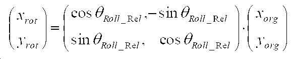
상기 <수학식 2>를 참조하면, 예를 들어 (xorg,yorg)의 픽셀의 사진 데이터를 (xrot,yrot)로 이동시키면 θRoll_Rel만큼 회전된 사진 데이터를 얻을 수 있다. 이러한 이미지 프로세싱을 통해 사진의 회전을 구현할 수 있다. 이러한 이미지 변환 과정에서 잘림(crop)이 발생할 수 있기 때문에, 사진의 해상도를 유지하기 위해서는 원하는 사진 사이즈보다 큰 이미지 센서를 사용하는 것이 적합하다.
Referring to <
도 10은 본 발명의 일 실시예에 따른 이미지 데이터 회전 동작을 위한 무선 렌즈부 100에 의한 처리 흐름을 보여주는 도면이다. 이 처리 흐름은 무선 렌즈부 100과 본체 200이 분리된 경우에도 본체 200을 사용하여 구도를 제어할 수 있는 방안을 제공한다. 10 is a view showing a processing flow by the
도 10을 참조하면, S110단계에서 무선 렌즈부 100에 실장된 이동궤적 측정기 170으로서 자이로스코프 센서가 활성화한다. S120단계에서 무선 렌즈부 100은 자이로스코프 센서의 Roll 정보 θRoll_Lens를 측정한다. S130단계에서 무선 렌즈부 100은 본체 200으로부터 자이로스코프의 Roll 정보 θRoll_Body를 수신한다. S140단계에서 무선 렌즈부 100은 수신된 정보 θRoll_Body와 측정된 정보 θRoll_Lens의 차이 θRoll_Rel를 계산한다. S150단계에서 무선 렌즈부 100은 이미지의 회전 방식을 결정한다. 만약 렌즈부 100이 이미지 센서 120의 기계적인 회전을 제공한다면, S160단계에서 무선 렌즈부 100은 모터 125를 사용하여 이미지 센서 120를 θRoll_Rel만큼 회전시킨다. 만약 렌즈부 100이 이미지 센서 120의 기계적인 회전을 제공하지 않는다면, S170단계에서 무선 렌즈부 100은 상기 <수학식 2>에 나타낸 바와 같은 좌표변환 식을 이용하여 이미지를 θRoll_Rel만큼 회전시킨다. S180단계에서 무선 렌즈부 100은 무선 렌즈부 100과 본체 200이 결합되었는지 여부를 판단한다. 무선 렌즈부 100과 본체 200이 결합된 경우에는 동작을 종료하고, 결합되지 않은 경우에는 S120단계로 되돌아가서 S120단계 내지 S170단계의 동작을 수행한다.
Referring to FIG. 10, in step S110, the gyroscope sensor is activated as a
도 11은 본 발명의 일 실시예에 따른 이미지 데이터 회전 동작을 위한 본체 200에 의한 처리 흐름을 보여주는 도면이다. 이 처리 흐름은 무선 렌즈부 100과 본체 200이 분리된 경우에도 본체 200을 사용하여 구도를 제어할 수 있는 방안을 제공한다. 11 is a view showing a processing flow by the
도 11을 참조하면, S210단계에서 본체 200에 실장된 이동궤적 측정기 260으로서 자이로스코프 센서가 활성화한다. S220단계에서 본체 200은 자이로스코프 센서의 Roll 정보 θRoll_Body를 측정한다. S230단계에서 본체 200은 무선 렌즈부 100으로 자이로스코프의 Roll 정보 θRoll_Body를 송신한다. S240단계에서 본체 200은 무선 렌즈부 100과 본체 200이 결합되었는지 여부를 판단한다. 무선 렌즈부 100과 본체 200이 결합된 경우에는 동작을 종료하고, 결합되지 않은 경우에는 S220단계로 되돌아가서 S220단계 내지 S230단계의 동작을 수행한다. Referring to FIG. 11, in step S210, the gyroscope sensor is activated as a
전술한 도 10 및 도 11에 도시된 과정들은 렌즈부 100과 본체 200이 분리된 상태에서, 사용자가 본체 200을 기반으로 구도를 제어하도록 설정한 경우 주기적으로 계속해서 반복된다. 만약 본체 200과 무선 렌즈부 100이 결합된 경우나 본체 100에 기반한 구도 제어 설정 기능이 오프(OFF)된 경우에는, 도 10 및 도 11에 도시된 과정들이 중지된다. 이러한 경우 도 2a 및 도 2b의 이미지 프로세서 130은 θRoll_Rel = 0이 되도록 기계적인 회전이나 이미지 프로세싱을 초기화할 수 있다. The above-described processes shown in FIGS. 10 and 11 are repeatedly repeated periodically when the user sets the control of composition based on the
한편, 전술한 본체 200에 기반한 구도 제어 동작 수행시 무선 렌즈부 100의 자이로스코프 센서를 포함하지 않는 방법도 가능하다. 이러한 경우 θRoll_Rel의 계산에 있어 θRoll_Lens = 0으로 하고, 이를 바탕으로 렌즈부 100의 이미지 센서 120을 회전시키거나 이미지 자체를 회전시킨다.
On the other hand, when performing the composition control operation based on the above-described
도 12는 본 발명의 다른 실시예에 따른 이미지 데이터 줌 처리 동작을 위한 무선 렌즈부 100 및 본체 200의 상호 동작을 설명하기 위한 도면이다. 이러한 본 발명의 실시예에 따르면, 렌즈 분리형 카메라에서 본체 200과 무선 렌즈부 100이 분리된 경우 사용자는 본체 200을 통해 이미지 데이터에 대한 줌인/줌아웃 처리를 제어한다. 일 실시예에 따르면, 줌인/줌아웃 처리는 가속도 센서 또는 유사한 센서를 사용하여 구현될 수 있다. 이러한 줌인/줌아웃 처리는 디스플레이에 구현된 UI(User Interface)를 통해서도 구현될 수 있다. 12 is a view for explaining the mutual operation of the
도 12를 참조하면, 만약 사용자가 본체 200을 앞으로 이동시킬 경우, 본체 200에 실장된 이동궤적 측정기 260으로서 가속도 센서는 (+)가속도를 측정한다. 반대로 사용자가 본체 200을 뒤로 이동시킬 경우, 본체 200에 실장된 이동궤적 측정기 260으로서 가속도 센서는 (-)가속도를 측정한다. 본체 200은 측정된 가속도 값 또는 가속도의 부호를 무선 링크를 통해 무선 렌즈부 100으로 송신한다. 그러면 무선 렌즈부 100은 수신된 가속도 정보를 사용하여 렌즈 제어부 150을 제어함으로써 광학 렌즈 110의 초점거리를 조절하고, 촬영되는 화면에 대해 줌인/줌아웃을 실행할 수 있다. Referring to FIG. 12, if the user moves the
무선 렌즈부 100과 본체 200이 분리된 상태에서 본체 200을 앞으로 이동할 경우, 가속도 센서에 의해 측정된 (+)가속도에 의해 무선 렌즈부 100은 광학 렌즈 110의 초점거리를 증가시킨다. 그러면 무선 렌즈부 100은 촬영된 이미지 데이터를 줌인 처리하고, 줌인된 이미지 데이터를 본체 200으로 송신한다. 이에 따라 본체 200은 줌인된 화면을 얻을 수 있다. 반대로 무선 렌즈부 100과 본체 200이 분리된 상태에서 본체 200을 뒤로 이동할 경우, 가속도 센서에 의해 측정된 (-)가속도에 의해 무선 렌즈부 100은 광학 렌즈 110의 초점거리를 감소시킨다. 그러면 무선 렌즈부 100은 촬영된 이미지 데이터를 줌아웃 처리하고, 줌아웃된 이미지 데이터를 본체 200으로 송신한다. 이에 따라 본체 200은 줌아웃된 화면을 얻을 수 있다. 만약 광학 렌즈 110의 초점거리 변경으로 줌인[/줌아웃] 처리가 더이상 불가능할 경우 디지털 줌을 사용할 수 있다. When the
한편 본 발명의 실시예에 따른 줌인/줌아웃 처리 기능의 수행을 위해 본체 200에는 제스쳐 인식 버튼이 구비될 수 있다. 제스쳐 인식 버튼이 눌리어졌을 때에만 본체 200의 앞뒤 움직임에 따라 줌인/줌아웃이 실행되도록 하기 위한 것이다. 일 실시예에서, 제스쳐 인식 버튼은 터치 스크린이 포함된 디스플레이 250에 UI로 구현될 수 있다. 다른 실시예에서, 제스쳐 인식 버튼은 기계적인 버튼으로 구현될 수 있다.
Meanwhile, in order to perform a zoom-in/zoom-out processing function according to an embodiment of the present invention, a gesture recognition button may be provided on the
도 13은 본 발명의 일 실시예에 따른 이미지 데이터 줌 처리 동작을 위한 무선 렌즈부 100에 의한 처리 흐름을 보여주는 도면이다. 이러한 처리 흐름은 렌즈 분리형 카메라에서 본체 200과 무선 렌즈부 100이 분리된 상태에서 사용자가 본체 200을 통해 이미지 데이터에 대한 줌인/줌아웃 처리를 제어하는 경우의 무선 렌즈부 100의 처리 동작에 해당한다.13 is a view showing a processing flow by the
도 13을 참조하면, S310단계에서 무선 렌즈부 100은 본체 200에 의해 측정된 가속도 센서 값에 대응하는 가속도 정보를 수신한다. 가속도 정보는 가속도의 부호 또는 가속도의 값이 될 수 있다. 가속도 정보를 수신한 무선 렌즈부 100은 가속도의 부호 또는 값에 따라 무선 렌즈부 100에 포함된 광학 렌즈 110의 초점거리를 변경한다. 만약 본체 200의 가속도 센서가 측정한 가속도가 (+)인 것으로 확인된 경우(S320단계), S330단계에서 무선 렌즈부 100은 광학 렌즈 110의 초점거리를 증가시킴으로써 이미지 데이터가 줌인 처리되도록 한다. 만약 본체 200의 가속도 센서가 측정한 가속도가 (-)인 것으로 확인된 경우(S320단계), S340단계에서 무선 렌즈부 100은 광학 렌즈 110의 초점거리를 감소시킴으로써 이미지 데이터가 줌아웃 처리되도록 한다. 일 실시예에서, 가속도 값의 크기가 클 경우 초점거리 변환은 더 빠른 속도로 이루어지고, 가속도 값이 작을 경우 초점거리 변환은 천천히 이루어진다. 이후 줌인/줌아웃 처리된 이미지 데이터는 본체 200으로 전송되고, 이에 따라 본체 200의 디스플레이 250에 표시되는 화면은 줌인/줌아웃 된다. S350단계에서 무선 렌즈부 100은 무선 렌즈부 100과 본체 200이 결합되었는지 여부를 판단한다. 무선 렌즈부 100과 본체 200이 결합된 경우에는 동작을 종료하고, 결합되지 않은 경우에는 S310단계로 되돌아가서 S310단계 내지 S340단계의 동작을 수행한다.
Referring to FIG. 13, in step S310, the
도 14는 본 발명의 일 실시예에 따른 이미지 데이터 줌 처리 동작을 위한 본체 200에 의한 처리 흐름을 보여주는 도면이다. 이러한 처리 흐름은 렌즈 분리형 카메라에서 본체 200과 무선 렌즈부 100이 분리된 상태에서 사용자가 본체 200을 통해 이미지 데이터에 대한 줌인/줌아웃 처리를 제어하는 경우의 본체 200의 처리 동작에 해당한다. 14 is a view showing a processing flow by the
도 14를 참조하면, S410단계에서 본체 200은 제스처 인식버튼이 눌리었는지 여부를 판단한다. 제스처 인식버튼이 눌리어진 경우, S420단계에서 본체 200은 가속도 센서의 값을 측정하고, 측정된 가속도의 부호 또는 가속도 값을 무선 렌즈부 100으로 전송한다. 그러면 가속도 정보를 수신한 무선 렌즈부 100은 가속도의 부호 또는 값에 따라 무선 렌즈부 100에 포함된 광학 렌즈 110의 초점거리를 변경함으로써 촬영된 이미지 데이터를 줌인 또는 줌아웃 처리한다. 이렇게 줌인/줌아웃 처리된 이미지 데이터는 본체 200으로 전송된다. Referring to FIG. 14, in step S410, the
S430단계에서 본체 200은 무선 렌즈부 100으로부터의 줌인/줌아웃 처리된 이미지 데이터를 수신하고, 디스플레이 250에 표시되는 화면을 줌인/줌아웃 처리한다. S440단계에서 본체 200은 무선 렌즈부 100과 본체 200이 결합되었는지 여부를 판단한다. 무선 렌즈부 100과 본체 200이 결합된 경우에는 동작을 종료하고, 결합되지 않은 경우에는 S410단계로 되돌아가서 S410단계 내지 S430단계의 동작을 수행한다.
In step S430, the
앞서서 설명한 도 13 및 도 14에 도시된 과정은 무선 렌즈부 100과 본체 200이 분리되어 있는 상태에서 본체 200에 구비된 제스쳐인식 버튼이 눌릴 경우 실행될 수 있고, 무선 렌즈부 100과 본체 200이 결합되면 중단될 수 있다. 도 13 및 도 14에 도시된 실시예와 달리, 도 6에 도시된 바와 같이 제어기 132는 이미지 센서 120으로부터 수신된 이미지 데이터를 수신기 142에 의해 수신된 본체 200의 전방/후방 이동 정보에 따라 줌인/줌아웃 처리하여 줌인/줌아웃 이미지 데이터를 출력할 수 있다. 예를 들면, 제어기 132는 본체 200의 이동 방향을 나타내는 가속도 센서 값이 (+)인 경우 이미지 데이터를 줌인 처리하고, 본체 200의 이동 방향을 나타내는 가속도 센서 값이 (-)인 경우 이미지 데이터를 줌아웃 처리한다.
The processes illustrated in FIGS. 13 and 14 described above may be executed when the gesture recognition button provided on the
전술한 바와 같이 본 발명의 실시예들에 따르면, 렌즈 분리형 카메라에서 무선 렌즈부와 본체에는 기울어짐, 회전, 앞 뒤 움직임 등과 같은 이동 궤적을 파악할 수 있는 자이로스코프센서/가속도 센서와 같은 이동 궤적 측정기가 구비된다. 무선 렌즈부 또는 본체는 이동 궤적 측정기에 의해 측정된 이동 궤적 정보를 무선 링크를 통해 상대방에게 전달한다. 무선 렌즈부 또는 본체는 수신된 상대방의 궤적 정보를 조합하여 촬영된 사진 및 동영상의 이미지 데이터를 회전, 확대, 축소 등을 결정하고 이를 사진 및 동영상 촬영에 반영한다. 일 실시예에 따르면, 무선 렌즈부와 본체가 분리되어 있는 상태에서, 본체를 가로, 세로 또는 임의의 기울기로 회전시키면 본체의 이동 궤적 측정기는 본체의 이동 궤적 정보를 측정하여 무선 렌즈부로 송신한다. 그러면 무선 렌즈부는 프리뷰 동영상, 촬영 이미지 등도 본체와 동일하게 가로, 세로 또는 임의의 기울기로 회전 처리한다. 다른 실시예에 따르면, 무선 렌즈부와 본체가 분리되어 있는 상태에서, 본체를 앞으로/뒤로 이동시 본체의 이동 궤적 측정기는 본체의 이동 궤적 정보를 측정하여 무선 렌즈부로 송신한다. 그러면 무선 렌즈부는 본체의 움직임에 따라 렌즈의 초점거리를 조절하고, 촬영된 이미지 데이터를 줌인/줌아웃 처리한다. 따라서, 본 발명의 실시예들은 무선 렌즈부와 본체가 분리된 경우에도 사진 및 동영상 촬영시 본체를 사용하여 효과적으로 사진 및 동영상의 촬영 구도를 변경할 수 있으며, 본체를 앞뒤로 움직임으로써 줌인/줌아웃을 쉽게 구현할 수 있다. According to the embodiments of the present invention as described above, in a lens-separated camera, a movement trajectory measuring device such as a gyroscope sensor/acceleration sensor capable of grasping movement trajectories such as tilting, rotation, forward and backward movement, etc. in the wireless lens unit and the main body Is provided. The wireless lens unit or the main body transmits the movement trajectory information measured by the movement trajectory meter to the other party through the radio link. The wireless lens unit or the main body determines the rotation, enlargement, reduction, etc. of image data of the photographed picture and video by combining trajectory information of the received counterpart and reflects it in the picture and video shooting. According to an embodiment, when the wireless lens unit and the main body are separated, when the main body is rotated horizontally, vertically, or at an arbitrary inclination, the motion trajectory meter of the main body measures the motion trajectory information of the main body and transmits it to the wireless lens unit. Then, the wireless lens unit rotates the preview video, the captured image, and the like in a horizontal, vertical, or arbitrary inclination as in the main body. According to another embodiment, when the main body is separated from the wireless lens unit, when the main body is moved forward/backward, the main body trajectory measuring device measures the main body trajectory information and transmits it to the wireless lens unit. Then, the wireless lens unit adjusts the focal length of the lens according to the movement of the main body, and zooms in/out the photographed image data. Accordingly, embodiments of the present invention can effectively change the composition of photographs and videos using the main body when taking pictures and videos even when the wireless lens unit and the main body are separated, and easily implement zoom-in/zoom-out by moving the main body back and forth. You can.
이상과 같이 본 발명은 비록 한정된 실시예와 도면에 의해 설명되었으나 본 발명은 상기의 실시예에 한정되는 것은 아니며 본 발명이 속하는 분야에서 통상의 지식을 가진 자라면 이러한 기재로부터 다양한 수정 및 변형이 가능하다. 예를 들어, 본 발명의 실시예들은 도 1에 도시된 바와 같이 무선 렌즈부 100과 본체 200으로 구성되는 렌즈 분리형 카메라 시스템에 적용되는 경우로 설명되었으나, 본체 200은 카메라 본체 뿐만 아니라 디스플레이를 구비하는 스마트폰, TV, 태블릿, 랩탑 등이 될 수 있으며, 무선 렌즈부 100도 스마트 카메라가 될 수 있다. 다른 예로, 본 발명의 실시예들에서는 무선 렌즈부 100이 도 2a, 도 2b, 도 5a, 도 b 또는 도 6에 도시된 바와 같이 구성되고 도 10 및 도 13에 도시된 흐름들과 같이 동작하고, 본체 200이 도 2a 또는 도 2b에 도시된 바와 같이 구성되고 도 11 및 도 14에 도시된 흐름들과 같이 동작하는 경우로 설명하였으나, 본 발명의 보호범위는 반드시 이에 한정되지는 않을 것이다. 본 발명의 실시예들에 따른 동작들은 단일의 프로세서에 의해서도 그 동작이 구현될 수 있을 것이다. 이러한 경우 다양한 컴퓨터로 구현되는 동작을 수행하기 위한 프로그램 명령이 컴퓨터 판독 가능 매체에 기록될 수 있다. 상기 컴퓨터 판단 가능 매체는 프로그램 명령, 데이터 파일, 데이터 구조 등을 단독으로 또는 조합하여 포함할 수 있다. 상기 프로그램 명령은 본 발명을 위하여 특별히 설계되고 구성된 것들이거나 당업자에게 공지되어 사용 가능한 것일 수도 있다. 컴퓨터 판독 가능 기록 매체의 예에는 하드 디스크, 플로피 디스크 및 자기 테이프와 같은 자기 매체, CD-ROM이나 DVD와 같은 광기록 매체, 플롭티컬 디스크(floptical disk)와 같은 자기-광 매체 및 롬(ROM), 램(RAM), 플래시 메모리 등과 같은 프로그램 명령을 저장하고 수행하도록 특별히 구성된 하드웨어 장치가 포함된다. 프로그램 명령의 예에는 컴파일러에 의해 만들어지는 것과 같은 기계어 코드 뿐만 아니라 인터프리터 등을 사용해서 컴퓨터에 의해서 실행될 수 있는 고급 언어 코드를 포함한다. 그러므로 본 발명의 범위는 설명된 실시예에 국한되어 정해져서는 아니되며, 후술하는 특허청구범위 뿐만 아니라 이 특허청구범위와 균등한 것들에 의해 정해져야 할 것이다.
As described above, although the present invention has been described by limited embodiments and drawings, the present invention is not limited to the above embodiments, and various modifications and variations can be made from these descriptions by those skilled in the art to which the present invention pertains. Do. For example, although the embodiments of the present invention have been described as being applied to a lens-separated camera system composed of a
100 : 무선 렌즈부 110: 렌즈들
120: 이미지 센서 130: 이미지 프로세서
140: 무선 모듈 150: 렌즈 제어부
160: 전원 장치 170: 이동 궤적 측정기
200: 본체 210: 무선 모듈
220: 저장장치 230: 사용자 입력장치
240: 전원장치 250: 디스플레이
260: 이동 궤적 측정기 100: wireless lens unit 110: lenses
120: image sensor 130: image processor
140: wireless module 150: lens control
160: power supply 170: moving trajectory meter
200: main body 210: wireless module
220: storage device 230: user input device
240: power supply 250: display
260: moving trajectory meter
Claims (42)
상기 본체로부터, 상기 본체의 제1 움직임에 대한 정보를 수신하는 과정과,
상기 렌즈부의 제2 움직임을 검출하는 과정과,
상기 제1 움직임 및 상기 제2 움직임에 기반하여 상기 렌즈부에 의해 촬영된 이미지 데이터를 변환 처리하는 과정을 포함하고,
상기 렌즈부는 상기 본체에 장착 및 탈착 가능하며 상기 본체에 무선으로 접속될 수 있는 방법.
In the camera system including the main body and the lens unit, in the operation method of the lens unit,
Receiving information about the first movement of the main body from the main body,
Detecting a second movement of the lens unit,
And converting image data photographed by the lens unit based on the first movement and the second movement,
The lens unit can be attached to and detached from the main body and can be wirelessly connected to the main body.
미리 정해진 기준 축에 대한 상기 렌즈부의 회전 기울기를 측정하는 과정을 포함하는 방법.
The method according to claim 1, The process of detecting the second movement of the lens unit,
And measuring a tilt of rotation of the lens unit with respect to a predetermined reference axis.
상기 미리 정해진 기준 축에 대한 상기 본체의 회전 기울기 정보를 수신하는 과정을 포함하는 방법.
The method according to claim 2, The process of receiving information about the first movement of the main body,
And receiving rotation tilt information of the main body with respect to the predetermined reference axis.
상기 미리 정해진 기준 축에 대한 상기 본체의 회전 기울기와 상기 렌즈부의 회전 기울기 사이의 기울기 차이만큼 상기 이미지 데이터를 회전시키는 과정을 포함하는 방법.
The method according to claim 3, wherein the process of converting the image data based on the first movement and the second movement,
And rotating the image data by a difference in the slope between the rotation slope of the main body and the rotation slope of the lens unit with respect to the predetermined reference axis.
촬영을 위한 이미지 센서를 상기 기울기 차이만큼 기계적으로 회전시킴으로써 상기 이미지 데이터를 회전시키거나,
상기 이미지 센서에 의해 출력된 상기 촬영된 이미지 데이터의 각 픽셀에 대한 좌표를 상기 기울기 차이만큼 회전시킴으로써 회전된 좌표를 가지는 이미지 데이터를 출력하는 과정을 포함하는 방법.
The method according to claim 4, The process of rotating the image data,
The image data is rotated by rotating the image sensor for shooting by the difference in tilt, or
And outputting image data having the rotated coordinates by rotating the coordinates for each pixel of the captured image data output by the image sensor by the difference in tilt.
미리 정해진 기준 축에 대하여 상기 본체가 이동한 방향에 대한 정보를 수신하는 과정을 포함하는 방법.
The method according to claim 1, The process of receiving information about the first movement of the main body,
And receiving information about a direction in which the main body has moved with respect to a predetermined reference axis.
상기 본체가 이동한 방향에 대한 정보에 기반하여 상기 이미지 데이터를 줌인 또는 줌아웃 처리하는 과정을 포함하는 방법.
The method according to claim 6, wherein the process of converting the image data based on the first motion and the second motion,
And zooming in or zooming out the image data based on information on a direction in which the main body has moved.
상기 본체로부터, 상기 본체의 제1 움직임에 대한 정보를 수신하도록 구성된 수신기;
상기 렌즈부의 제2 움직임을 검출하도록 구성된 센서; 및
상기 제1 움직임 및 상기 제2 움직임에 기반하여 상기 렌즈부로부터 촬영된 이미지 데이터를 변환 처리하도록 구성된 적어도 하나의 제어기를 포함하고,
상기 렌즈부는 상기 본체에 장착 및 탈착 가능하며 상기 본체에 무선으로 접속될 수 있는 렌즈부.
In the lens portion of the camera system comprising a body and a lens portion,
A receiver configured to receive information on the first movement of the main body from the main body;
A sensor configured to detect a second movement of the lens unit; And
And at least one controller configured to convert image data captured from the lens unit based on the first movement and the second movement,
The lens unit is a lens unit that can be attached to and detached from the main body and can be wirelessly connected to the main body.
미리 정해진 기준 축에 대한 상기 렌즈부의 회전 기울기를 측정하도록 더 구성된 렌즈부.
The method according to claim 8, The sensor,
The lens unit further configured to measure the rotational tilt of the lens unit with respect to a predetermined reference axis.
상기 미리 정해진 기준 축에 대한 상기 본체의 회전 기울기 정보를 수신하도록 더 구성된 렌즈부.
The method according to claim 9, The receiver,
The lens unit further configured to receive rotation tilt information of the main body with respect to the predetermined reference axis.
상기 미리 정해진 기준 축에 대하여 상기 본체의 회전 기울기와 상기 렌즈부의 회전 기울기 사이의 기울기 차이만큼 상기 이미지 데이터를 회전시키도록 더 구성된 렌즈부.
The method according to claim 10, The sensor,
The lens unit is further configured to rotate the image data by a difference in tilt between the rotation gradient of the main body and the rotation gradient of the lens unit with respect to the predetermined reference axis.
촬영을 위한 이미지 센서를 상기 기울기 차이만큼 기계적으로 회전시킴으로써 상기 이미지 데이터를 회전시키거나,
이미지 센서에 의해 출력된 상기 촬영된 이미지 데이터의 각 픽셀에 대한 좌표를 상기 기울기 차이만큼 회전시킴으로써 회전된 좌표를 가지는 이미지 데이터를 출력하는 렌즈부.
The method according to claim 11, The sensor,
The image data is rotated by rotating the image sensor for shooting by the difference in tilt, or
A lens unit that outputs image data having rotated coordinates by rotating coordinates for each pixel of the photographed image data output by an image sensor by the difference in tilt.
미리 정해진 기준 축에 대하여 상기 본체가 이동한 방향에 대한 정보를 수신하도록 더 구성된 렌즈부.
The method according to claim 8, The receiver,
A lens unit further configured to receive information on a direction in which the main body has moved with respect to a predetermined reference axis.
상기 이동한 방향에 대한 정보에 기반하여 상기 이미지 데이터를 줌인 또는 줌아웃 하도록 더 구성된 렌즈부.
The method according to claim 13, The at least one controller,
A lens unit further configured to zoom in or zoom out the image data based on information about the moved direction.
Priority Applications (4)
| Application Number | Priority Date | Filing Date | Title |
|---|---|---|---|
| KR1020130125493A KR102122472B1 (en) | 2013-10-21 | 2013-10-21 | Method and apparatus in a camera with interchangeble lens |
| US15/030,791 US10165173B2 (en) | 2013-10-21 | 2014-10-21 | Operating method and apparatus for detachable lens type camera |
| EP14856029.5A EP3062503B1 (en) | 2013-10-21 | 2014-10-21 | Operating method and apparatus for detachable lens type camera |
| PCT/KR2014/009866 WO2015060605A1 (en) | 2013-10-21 | 2014-10-21 | Operating method and apparatus for detachable lens type camera |
Applications Claiming Priority (1)
| Application Number | Priority Date | Filing Date | Title |
|---|---|---|---|
| KR1020130125493A KR102122472B1 (en) | 2013-10-21 | 2013-10-21 | Method and apparatus in a camera with interchangeble lens |
Publications (2)
| Publication Number | Publication Date |
|---|---|
| KR20150045792A KR20150045792A (en) | 2015-04-29 |
| KR102122472B1 true KR102122472B1 (en) | 2020-06-12 |
Family
ID=52993140
Family Applications (1)
| Application Number | Title | Priority Date | Filing Date |
|---|---|---|---|
| KR1020130125493A KR102122472B1 (en) | 2013-10-21 | 2013-10-21 | Method and apparatus in a camera with interchangeble lens |
Country Status (4)
| Country | Link |
|---|---|
| US (1) | US10165173B2 (en) |
| EP (1) | EP3062503B1 (en) |
| KR (1) | KR102122472B1 (en) |
| WO (1) | WO2015060605A1 (en) |
Families Citing this family (2)
| Publication number | Priority date | Publication date | Assignee | Title |
|---|---|---|---|---|
| KR102531976B1 (en) | 2016-02-05 | 2023-05-12 | 삼성전자주식회사 | Electronic apparatus, portable device, and the control method thereof |
| US11095807B2 (en) * | 2019-01-23 | 2021-08-17 | Giovanni Sacco | Method and apparatus for the correction of geometric and depth of field problems during image taking |
Citations (2)
| Publication number | Priority date | Publication date | Assignee | Title |
|---|---|---|---|---|
| US20100073492A1 (en) * | 2008-09-24 | 2010-03-25 | Canon Kabushiki Kaisha | Imaging apparatus and method for controlling the same |
| JP2010109477A (en) * | 2008-10-28 | 2010-05-13 | Canon Inc | Imaging apparatus, control method thereof and program |
Family Cites Families (15)
| Publication number | Priority date | Publication date | Assignee | Title |
|---|---|---|---|---|
| US7129986B2 (en) | 2002-01-23 | 2006-10-31 | Guan-Wu Wang | Wireless camera system |
| TWM253170U (en) | 2004-02-10 | 2004-12-11 | Jiun-Bei Chang | Interface device of detached and externally connected camera lens |
| JP2005278020A (en) * | 2004-03-26 | 2005-10-06 | Fuji Photo Film Co Ltd | Remote photographing device |
| US7593055B2 (en) | 2004-07-27 | 2009-09-22 | Fujifilm Corporation | Camera system, camera main body, and camera head |
| JP2007116474A (en) | 2005-10-20 | 2007-05-10 | Fujifilm Corp | Camera system |
| US7616232B2 (en) | 2005-12-02 | 2009-11-10 | Fujifilm Corporation | Remote shooting system and camera system |
| JP5011387B2 (en) | 2007-07-13 | 2012-08-29 | パナソニック株式会社 | Imaging device |
| JP2011004391A (en) | 2009-05-21 | 2011-01-06 | Panasonic Corp | Camera system, camera body and interchangeable lens unit |
| CN101969530B (en) * | 2009-07-27 | 2014-02-19 | 鸿富锦精密工业(深圳)有限公司 | Camera module |
| JP5413133B2 (en) * | 2009-11-05 | 2014-02-12 | 株式会社リコー | CAMERA BODY, IMAGE PICKUP UNIT AND IMAGE PICKUP DEVICE detachably attached to the camera body |
| JP2011259065A (en) | 2010-06-07 | 2011-12-22 | Ricoh Co Ltd | Imaging apparatus |
| US10560621B2 (en) * | 2010-11-19 | 2020-02-11 | Symbol Technologies, Llc | Methods and apparatus for controlling a networked camera |
| US9414634B2 (en) | 2011-11-23 | 2016-08-16 | Jeffrey L. Gindin | Camera equipped helmet |
| KR20130061511A (en) * | 2011-12-01 | 2013-06-11 | 삼성전자주식회사 | Digital photographing system and method for operating digital photographing system |
| JP5746244B2 (en) * | 2013-03-06 | 2015-07-08 | オリンパス株式会社 | Imaging operation terminal, imaging system, imaging operation method, and program |
-
2013
- 2013-10-21 KR KR1020130125493A patent/KR102122472B1/en active IP Right Grant
-
2014
- 2014-10-21 EP EP14856029.5A patent/EP3062503B1/en active Active
- 2014-10-21 WO PCT/KR2014/009866 patent/WO2015060605A1/en active Application Filing
- 2014-10-21 US US15/030,791 patent/US10165173B2/en active Active
Patent Citations (2)
| Publication number | Priority date | Publication date | Assignee | Title |
|---|---|---|---|---|
| US20100073492A1 (en) * | 2008-09-24 | 2010-03-25 | Canon Kabushiki Kaisha | Imaging apparatus and method for controlling the same |
| JP2010109477A (en) * | 2008-10-28 | 2010-05-13 | Canon Inc | Imaging apparatus, control method thereof and program |
Also Published As
| Publication number | Publication date |
|---|---|
| EP3062503B1 (en) | 2019-12-04 |
| EP3062503A1 (en) | 2016-08-31 |
| KR20150045792A (en) | 2015-04-29 |
| US10165173B2 (en) | 2018-12-25 |
| US20160255265A1 (en) | 2016-09-01 |
| WO2015060605A1 (en) | 2015-04-30 |
| EP3062503A4 (en) | 2017-03-22 |
Similar Documents
| Publication | Publication Date | Title |
|---|---|---|
| US9019387B2 (en) | Imaging device and method of obtaining image | |
| US20160277681A1 (en) | Image capturing apparatus capable of capturing panoramic image | |
| US9628719B2 (en) | Read-out mode changeable digital photographing apparatus and method of controlling the same | |
| US20150271414A1 (en) | Display apparatus and display method | |
| US20120257007A1 (en) | Image processing device capable of generating wide-range image | |
| US10362231B2 (en) | Head down warning system | |
| US8547454B2 (en) | Digital image photographing apparatuses and methods of controlling the same to provide location information | |
| US11120272B2 (en) | Imaging apparatus, electronic device, and method of transmitting image data | |
| KR102122472B1 (en) | Method and apparatus in a camera with interchangeble lens | |
| JP2012090216A (en) | Imaging device and control method for imaging device | |
| JP7131541B2 (en) | Image processing device, image processing method and image processing program | |
| CN108476290B (en) | Electronic device for providing panoramic image and control method thereof | |
| US10250760B2 (en) | Imaging device, imaging system, and imaging method | |
| WO2022041013A1 (en) | Control method, handheld gimbal, system, and computer readable storage medium | |
| JP2015012550A (en) | Imaging apparatus and imaging system | |
| EP2490436A1 (en) | Image photographing apparatus and method using image stored in camera | |
| JP2013009039A (en) | Imaging device and control method therefor | |
| JP5182395B2 (en) | Imaging apparatus, imaging method, and imaging program | |
| JP2010062834A (en) | Photographing system, photographing device constituting the same, and operation device | |
| JP2020022065A (en) | Distribution device, camera device, distribution system, distribution method, and distribution program | |
| JP6202982B2 (en) | Image processing apparatus, control method thereof, and control program | |
| KR101643772B1 (en) | Apparatus and method for image capture using image stored in camera | |
| WO2022163390A1 (en) | Image processing device, control method, and program | |
| JP2012216885A (en) | Imaging apparatus and image sharing system | |
| JP2006145567A (en) | Camera, method for notifying camera shake amount of camera, and program |
Legal Events
| Date | Code | Title | Description |
|---|---|---|---|
| A201 | Request for examination | ||
| E902 | Notification of reason for refusal | ||
| E701 | Decision to grant or registration of patent right | ||
| GRNT | Written decision to grant |