KR102008030B1 - Image decoding method, image encoding method, image decoding device, image encoding device, and image encoding/decoding device - Google Patents
Image decoding method, image encoding method, image decoding device, image encoding device, and image encoding/decoding device Download PDFInfo
- Publication number
- KR102008030B1 KR102008030B1 KR1020137031357A KR20137031357A KR102008030B1 KR 102008030 B1 KR102008030 B1 KR 102008030B1 KR 1020137031357 A KR1020137031357 A KR 1020137031357A KR 20137031357 A KR20137031357 A KR 20137031357A KR 102008030 B1 KR102008030 B1 KR 102008030B1
- Authority
- KR
- South Korea
- Prior art keywords
- context
- block
- unit
- decoding
- type
- Prior art date
Links
Images


Classifications
-
- H—ELECTRICITY
- H04—ELECTRIC COMMUNICATION TECHNIQUE
- H04N—PICTORIAL COMMUNICATION, e.g. TELEVISION
- H04N19/00—Methods or arrangements for coding, decoding, compressing or decompressing digital video signals
- H04N19/90—Methods or arrangements for coding, decoding, compressing or decompressing digital video signals using coding techniques not provided for in groups H04N19/10-H04N19/85, e.g. fractals
- H04N19/91—Entropy coding, e.g. variable length coding [VLC] or arithmetic coding
-
- H—ELECTRICITY
- H04—ELECTRIC COMMUNICATION TECHNIQUE
- H04N—PICTORIAL COMMUNICATION, e.g. TELEVISION
- H04N19/00—Methods or arrangements for coding, decoding, compressing or decompressing digital video signals
- H04N19/46—Embedding additional information in the video signal during the compression process
- H04N19/463—Embedding additional information in the video signal during the compression process by compressing encoding parameters before transmission
-
- H—ELECTRICITY
- H04—ELECTRIC COMMUNICATION TECHNIQUE
- H04N—PICTORIAL COMMUNICATION, e.g. TELEVISION
- H04N19/00—Methods or arrangements for coding, decoding, compressing or decompressing digital video signals
- H04N19/10—Methods or arrangements for coding, decoding, compressing or decompressing digital video signals using adaptive coding
- H04N19/102—Methods or arrangements for coding, decoding, compressing or decompressing digital video signals using adaptive coding characterised by the element, parameter or selection affected or controlled by the adaptive coding
- H04N19/13—Adaptive entropy coding, e.g. adaptive variable length coding [AVLC] or context adaptive binary arithmetic coding [CABAC]
-
- H—ELECTRICITY
- H04—ELECTRIC COMMUNICATION TECHNIQUE
- H04N—PICTORIAL COMMUNICATION, e.g. TELEVISION
- H04N19/00—Methods or arrangements for coding, decoding, compressing or decompressing digital video signals
- H04N19/10—Methods or arrangements for coding, decoding, compressing or decompressing digital video signals using adaptive coding
- H04N19/134—Methods or arrangements for coding, decoding, compressing or decompressing digital video signals using adaptive coding characterised by the element, parameter or criterion affecting or controlling the adaptive coding
- H04N19/157—Assigned coding mode, i.e. the coding mode being predefined or preselected to be further used for selection of another element or parameter
-
- H—ELECTRICITY
- H04—ELECTRIC COMMUNICATION TECHNIQUE
- H04N—PICTORIAL COMMUNICATION, e.g. TELEVISION
- H04N19/00—Methods or arrangements for coding, decoding, compressing or decompressing digital video signals
- H04N19/10—Methods or arrangements for coding, decoding, compressing or decompressing digital video signals using adaptive coding
- H04N19/169—Methods or arrangements for coding, decoding, compressing or decompressing digital video signals using adaptive coding characterised by the coding unit, i.e. the structural portion or semantic portion of the video signal being the object or the subject of the adaptive coding
- H04N19/17—Methods or arrangements for coding, decoding, compressing or decompressing digital video signals using adaptive coding characterised by the coding unit, i.e. the structural portion or semantic portion of the video signal being the object or the subject of the adaptive coding the unit being an image region, e.g. an object
- H04N19/176—Methods or arrangements for coding, decoding, compressing or decompressing digital video signals using adaptive coding characterised by the coding unit, i.e. the structural portion or semantic portion of the video signal being the object or the subject of the adaptive coding the unit being an image region, e.g. an object the region being a block, e.g. a macroblock
-
- H—ELECTRICITY
- H04—ELECTRIC COMMUNICATION TECHNIQUE
- H04N—PICTORIAL COMMUNICATION, e.g. TELEVISION
- H04N19/00—Methods or arrangements for coding, decoding, compressing or decompressing digital video signals
- H04N19/10—Methods or arrangements for coding, decoding, compressing or decompressing digital video signals using adaptive coding
- H04N19/189—Methods or arrangements for coding, decoding, compressing or decompressing digital video signals using adaptive coding characterised by the adaptation method, adaptation tool or adaptation type used for the adaptive coding
- H04N19/196—Methods or arrangements for coding, decoding, compressing or decompressing digital video signals using adaptive coding characterised by the adaptation method, adaptation tool or adaptation type used for the adaptive coding being specially adapted for the computation of encoding parameters, e.g. by averaging previously computed encoding parameters
- H04N19/197—Methods or arrangements for coding, decoding, compressing or decompressing digital video signals using adaptive coding characterised by the adaptation method, adaptation tool or adaptation type used for the adaptive coding being specially adapted for the computation of encoding parameters, e.g. by averaging previously computed encoding parameters including determination of the initial value of an encoding parameter
Abstract
본 발명의 일형태에 관련된 화상 복호 방법은, 복수의 컨택스트 중, 처리 대상 블록에 사용하는 컨택스트를 결정하는 컨택스트 제어 단계(S204)와, 상기 처리 대상 블록에 대응하는 비트열을, 결정된 상기 컨택스트를 이용하여 산술 복호하는 산술 복호 단계(S210)를 포함하고, 상기 컨택스트 제어 단계(S204)에서는, 상기 제어 파라미터의 신호 종별이 제1종별인 경우에, 상기 처리 대상 블록에 인접하는 좌측 블록 및 상측 블록의 제어 파라미터를 함께 이용하는 조건을 이용하여 상기 컨택스트를 결정하고(S206), 상기 제어 파라미터의 신호 종별이 제2종별인 경우에, 상기 상측 블록의 제어 파라미터를 이용하지 않는 조건을 이용하여 상기 컨택스트를 결정한다(S207). In the image decoding method according to one embodiment of the present invention, among a plurality of contexts, a context control step (S204) for determining a context to be used for a processing target block and a bit string corresponding to the processing target block are determined. An arithmetic decoding step (S210) of performing arithmetic decoding using the context, and in the context control step (S204), when the signal type of the control parameter is the first type, the processing target block is adjacent to the processing target block. The context is determined using a condition of using the control parameters of the left block and the upper block together (S206), and the condition of not using the control parameter of the upper block when the signal type of the control parameter is the second type. Determine the context using (S207).

Description
본 발명은, 화상 복호 방법, 화상 부호화 방법, 화상 복호 장치, 화상 부호화 장치 및 화상 부호화 복호 장치에 관한 것으로, 특히, 산술 부호화 또는 산술 복호를 이용하는 화상 복호 방법, 화상 부호화 방법, 화상 복호 장치, 화상 부호화 장치 및 화상 부호화 복호 장치에 관한 것이다. BACKGROUND OF THE
자연 화상의 화상 신호는 통계적인 편차를 가지고 그 편차는 변동적인 행동을 한다. 통계 편차의 변동성을 이용한 엔트로피 부호화 방식의 1개에 Context-Based Adaptive Binary Arithmetic Coding(CABAC)이 존재한다(비특허 문헌 1을 참조). 이 CABAC 방식은 ITU-T/ISOIEC standard for video coding, H. 264/AVC 방식에 채용되어 있다. The image signal of the natural image has a statistical deviation, and the deviation has a variable behavior. Context-Based Adaptive Binary Arithmetic Coding (CABAC) exists in one of the entropy coding schemes using the variability of statistical variation (see Non-Patent Document 1). This CABAC method is adopted in the ITU-T / ISOIEC standard for video coding, H.264 / AVC method.
이하, CABAC 방식으로 이용되는 용어의 의미를 설명한다. Hereinafter, the meaning of the terms used in the CABAC method will be described.
(1) “Context-Based Adaptive”(컨택스트에 의거하여 적응)은, 부호화 및 복호 방법을, 통계의 편차의 변동에 적응시키는 것이다. 즉, “Context-Based Adaptive”은, 어떠한 심볼을 부호화 또는 복호하는 경우에, 주위의 조건의 발생 사상에 맞추어 당해 심볼의 발생 확률로서 적절한 확률을 예측하는 것이라고도 할 수 있다. 예를 들면, 부호화에 있어서는, 어떠한 심볼(S)의 각 값의 발생 확률 p(x)을 결정할 경우에, 실제로 일어난 사상 또는 사상의 열 F(z)을 조건으로 한 조건부 발생 확률을 이용한다. (1) "Context-Based Adaptive" (adaptation based on context) is to adapt the encoding and decoding method to variations in the deviation of statistics. In other words, "Context-Based Adaptive" may be said to predict the probability suitable as the occurrence probability of the said symbol according to the occurrence thought of the surrounding condition, when encoding or decoding a certain symbol. For example, in encoding, when determining the occurrence probability p (x) of each value of a symbol S, the conditional occurrence probability subject to the actual occurrence of the event or the column F (z) of the event is used.
(2) “Binary”(바이너리)는, 심볼을 바이너리 배열로 표현하는 것을 의미한다. 다치로 나타내는 심볼에 대해서는, 한번 bin string이라고 불리는 2치 배열로 변형한다. 그리고 배열 요소의 각각에 대하여 예측 확률(조건부 확률)을 전환하여 이용하면서, 2개의 값의 사상 중 어느 쪽이 발생했는지를 비트 열화한다. 이에 따라 신호 종별의 단위보다도 상세한 단위(바이너리 요소 단위)로 값의 확률을 관리(초기화 및 갱신)할 수 있다(비특허 문헌 1의 Fig. 2 등을 참조). (2) “Binary” (binary) means to represent a symbol as a binary array. For multivalued symbols, they are transformed into a binary array called a bin string. Then, the prediction deterioration (conditional probability) is used for each of the array elements, and bit degradation is performed on which of two event mappings has occurred. As a result, the probability of the value can be managed (initialized and updated) in more detailed units (binary element units) than in the unit of the signal type (see Fig. 2 of Non-Patent Document 1).
(3) “arithmetic” (산술)이란, 전술의 비트열 생성 처리가, 표에 의한 대응이 아니라 계산에 의해 출력된다는 것이다. H. 263, MPEG-4 및 H. 264에서의 가변 길이 부호표를 이용하는 부호화 방식에서는, 발생 확률이 0.5(50%)보다 높은 발생 확률을 가지는 심볼이라도, 심볼이 취할 수 있는 값의 각각을, 1개의 바이너리열(비트열)에 대응시킬 필요가 있다. 따라서, 가장 확률이 높은 값에 대해서도 최단에서도 1개의 심볼에 1비트를 대응시키지 않으면 안된다. 이에 대하여 산술 부호화는, 사상이 높은 확률에서의 발생을 정수값 1비트 이하로 표현할 수 있다. 예를 들면, 1바이너리째의 값이 「0」이 되는 발생 확률이 0.9(90%)을 초과하는 신호 종별이 있고, 사상으로서 1바이너리째의 값이 N회 연속하여 「0」인 경우, 각각의 값 「0」에 대하여 1비트의 데이터를 N회 출력할 필요가 없어진다. (3) "arithmetic" (arithmetic) means that the above-described bit string generation processing is output by calculation rather than correspondence with a table. In the coding scheme using the variable length code table in H. 263, MPEG-4, and H. 264, even if a symbol having a probability of occurrence is higher than 0.5 (50%), each of the values that the symbol can take, It must correspond to one binary string (bit string). Therefore, even for the most probable value, one bit must correspond to one symbol at the shortest. In contrast, arithmetic coding can express occurrences at high probability with an integer value of 1 bit or less. For example, when there is a signal type in which the occurrence probability that the value of the first binary number becomes "0" exceeds 0.9 (90%), and the value of the first binary number is "0" consecutively N times, respectively, It is not necessary to output 1 bit of data N times for the value "0".
그러나, 이러한 화상 부호화 방법 및 화상 복호 방법에 있어서는, 메모리 사용량(사용하는 메모리 용량)의 저감이 요망된다. However, in such a picture coding method and a picture decoding method, it is desired to reduce the memory usage (memory capacity to be used).
여기서, 본 발명은, 메모리 사용량을 삭감할 수 있는 화상 부호화 방법 또는 화상 복호 방법을 제공하는 것을 목적으로 한다. An object of the present invention is to provide a picture coding method or a picture decoding method which can reduce memory usage.
상기 목적을 달성하기 위해서, 본 발명의 일형태에 관련된 화상 복호 방법은, 산술 복호를 이용하는 화상 복호 방법으로서, 복수의 컨택스트 중, 처리 대상 블록에 사용하는 컨택스트를 결정하는 컨택스트 제어 단계와, 제어 파라미터가 산술 부호화됨으로써 얻어진, 상기 처리 대상 블록에 대응하는 비트열을, 결정된 상기 컨택스트를 이용하여 산술 복호함으로써 2치 배열을 복원하는 산술 복호 단계와, 상기 2치 배열을 다치화함으로써 상기 제어 파라미터를 복원하는 다치화 단계를 포함하고, 상기 컨택스트 제어 단계에서는, 상기 처리 대상 블록의 제어 파라미터의 신호 종별을 판정하고, 상기 신호 종별이 제1종별인 경우에, 상기 처리 대상 블록에 인접하는 좌측 블록 및 상측 블록의 복호가 끝난 제어 파라미터를 함께 이용하는 제1 조건을 이용하여 상기 컨택스트를 결정하고, 상기 신호 종별이, 상기 제1종별과 상이한 제2 종별인 경우에, 상기 상측 블록의 복호가 끝난 제어 파라미터를 이용하지 않는 제2 조건을 이용하여 상기 컨택스트를 결정한다. In order to achieve the above object, an image decoding method according to one embodiment of the present invention is an image decoding method using arithmetic decoding, comprising: a context control step of determining a context to be used for a processing target block among a plurality of contexts; And an arithmetic decoding step of restoring the binary array by arithmetic decoding the bit string corresponding to the processing target block obtained by the arithmetic coding of the control parameter using the determined context; And a multi-valued step of restoring a control parameter, wherein in the context control step, a signal type of a control parameter of the block to be processed is determined, and when the signal type is a first type, adjacent to the block to be processed. By using the first condition that uses the decoded control parameters of the left block and the upper block to The context is determined, and the context is determined using a second condition that does not use the decoded control parameter of the upper block when the signal type is a second type different from the first type. .
본 발명은, 메모리 사용량을 삭감할 수 있는 화상 부호화 방법 또는 화상 복호 방법을 제공할 수 있다. The present invention can provide an image coding method or an image decoding method which can reduce the memory usage.
도 1은 본 발명의 실시 형태 1에 관련된 화상 부호화 장치의 기능 블록도이다.
도 2는 본 발명의 실시 형태 1에 관련된 가변 길이 부호화부의 기능 블록도이다.
도 3은 본 발명의 실시 형태 1에 관련된 제어 파라미터의 컨택스트 모델에 관한 표이다.
도 4는 본 발명의 실시 형태 1에 관련된 산술 부호화 방법을 나타내는 플로우도이다.
도 5는 본 발명의 실시 형태 2에 관련된 화상 복호 장치의 기능 블록도이다.
도 6은 본 발명의 실시 형태 2에 관련된 가변 길이 복호부의 기능 블록도이다.
도 7은 본 발명의 실시 형태 2에 관련된 산술 복호 방법을 나타내는 플로우도이다.
도 8은 본 발명의 실시 형태 2에 관련된 산술 복호 방법의 변형예를 나타내는 플로우도이다.
도 9는 본 발명의 실시 형태 2에 관련된 HEVC에 있어서의 분할 블록(트리 구조)을 나타내는 도면이다.
도 10은 본 발명의 실시 형태 2에 관련된 다계층 블록 구조를 설명하기 위한 도면이다.
도 11은 본 발명의 실시 형태 3에 관련된 split_coding_unit_flag의 산술 복호 방법을 나타내는 표이다.
도 12a는 본 발명의 실시 형태 3에 관련된 split_coding_unit_flag에 대한 검증 결과를 나타내는 표이다.
도 12b는 본 발명의 실시 형태 3에 관련된 split_coding_unit_flag에 대한 검증 결과를 나타내는 표이다.
도 13은 본 발명의 실시 형태 3에 관련된 skip_flag의 산술 복호 방법을 나타내는 표이다.
도 14a는 본 발명의 실시 형태 3에 관련된 skip_flag에 대한 검증 결과를 나타내는 표이다.
도 14b는 본 발명의 실시 형태 3에 관련된 skip_flag에 대한 검증 결과를 나타내는 표이다.
도 15는 본 발명의 실시 형태 3에 관련된 merge_flag의 산술 복호 방법을 나타내는 표이다.
도 16a는 본 발명의 실시 형태 3에 관련된 merge_flag에 대한 검증 결과를 나타내는 표이다.
도 16b는 본 발명의 실시 형태 3에 관련된 merge_flag에 대한 검증 결과를 나타내는 표이다.
도 17은 본 발명의 실시 형태에 관련된, 인접 2블록의 대응하는 제어 파라미터의 값을 이용하는 컨택스트 모델을 설명하기 위한 도면이다.
도 18은 본 발명의 실시 형태에 관련된, 상측 블록을 이용하는 경우의 메모리 사용량의 증가를 설명하기 위한 도면이다.
도 19는 컨텐츠 전송 서비스를 실현하는 컨텐츠 공급 시스템의 전체 구성도이다.
도 20은 디지털 방송용 시스템의 전체 구성도이다.
도 21은 텔레비전의 구성예를 나타내는 블록도이다.
도 22는 광 디스크인 기록 미디어에 정보의 읽고 쓰기를 행하는 정보 재생/기록부의 구성예를 나타내는 블록도이다.
도 23은 광 디스크인 기록 미디어의 구조예를 나타내는 도면이다.
도 24a는 휴대 전화의 일예를 나타내는 도면이다.
도 24b는 휴대 전화의 구성예를 나타내는 블록도이다.
도 25는 다중화 데이터의 구성을 나타내는 도면이다.
도 26은 각 스트림이 다중화 데이터에 있어서 어떻게 다중화되어 있는지를 모식적으로 나타내는 도면이다.
도 27은 PES 패킷 열에, 비디오 스트림이 어떻게 저장되는지를 더욱 상세하게 나타낸 도면이다.
도 28은 다중화 데이터에 있어서의 TS 패킷과 소스 패킷의 구조를 나타내는 도면이다.
도 29는 PMT의 데이터 구성을 나타내는 도면이다.
도 30은 다중화 데이터 정보의 내부 구성을 나타내는 도면이다.
도 31은 스트림 속성 정보의 내부 구성을 나타내는 도면이다.
도 32는 영상 데이터를 식별하는 단계를 나타내는 도면이다.
도 33은 각 실시의 형태의 동화상 부호화 방법 및 동화상 복호화 방법을 실현하는 집적 회로의 구성예를 나타내는 블록도이다.
도 34는 구동 주파수를 전환하는 구성을 나타내는 도면이다.
도 35는 영상 데이터를 식별하여, 구동 주파수를 전환하는 단계를 나타내는 도면이다.
도 36은 영상 데이터의 규격과 구동 주파수를 대응시킨 룩 업 테이블의 일예를 나타내는 도면이다.
도 37a는 신호 처리부의 모듈을 공유화하는 구성의 일예를 나타내는 도면이다.
도 37b는 신호 처리부의 모듈을 공유화하는 구성의 다른 일예를 나타내는 도면이다. 1 is a functional block diagram of a picture coding apparatus according to
2 is a functional block diagram of a variable length coding unit according to the first embodiment of the present invention.
3 is a table relating to a context model of control parameters according to
4 is a flowchart showing the arithmetic coding method according to the first embodiment of the present invention.
5 is a functional block diagram of the image decoding device according to
6 is a functional block diagram of a variable length decoding unit according to the second embodiment of the present invention.
Fig. 7 is a flowchart showing the arithmetic decoding method according to the second embodiment of the present invention.
8 is a flowchart showing a modification of the arithmetic decoding method according to the second embodiment of the present invention.
Fig. 9 is a diagram showing a divided block (tree structure) in HEVC according to the second embodiment of the present invention.
FIG. 10 is a diagram for explaining a multilayer block structure according to
11 is a table showing the arithmetic decoding method of split_coding_unit_flag according to the third embodiment of the present invention.
12A is a table showing a verification result for split_coding_unit_flag according to the third embodiment of the present invention.
12B is a table showing a verification result for split_coding_unit_flag according to the third embodiment of the present invention.
Fig. 13 is a table showing the arithmetic decoding method of skip_flag according to the third embodiment of the present invention.
14A is a table which shows the verification result about the skip_flag which concerns on
14B is a table which shows the verification result about the skip_flag which concerns on
Fig. 15 is a table showing the arithmetic decoding method of merge_flag according to the third embodiment of the present invention.
16A is a table which shows the verification result about merge_flag which concerns on
16B is a table which shows the verification result about the merge_flag which concerns on
FIG. 17 is a diagram for explaining a context model using values of corresponding control parameters of two adjacent blocks according to an embodiment of the present invention. FIG.
It is a figure for demonstrating the increase of the memory usage at the time of using an upper block which concerns on embodiment of this invention.
19 is an overall configuration diagram of a content supply system that realizes a content delivery service.
20 is an overall configuration diagram of a system for digital broadcasting.
21 is a block diagram illustrating an exemplary configuration of a television.
Fig. 22 is a block diagram showing an example of the configuration of an information reproducing / recording unit which reads and writes information to a recording medium which is an optical disc.
23 is a diagram showing an example of the structure of a recording medium which is an optical disk.
24A is a diagram illustrating an example of a mobile phone.
24B is a block diagram illustrating an exemplary configuration of a mobile phone.
25 is a diagram illustrating a configuration of multiplexed data.
Fig. 26 is a diagram schematically showing how each stream is multiplexed in multiplexed data.
27 is a diagram showing in more detail how video streams are stored in a PES packet sequence.
Fig. 28 is a diagram illustrating the structure of a TS packet and a source packet in multiplexed data.
29 is a diagram illustrating a data configuration of a PMT.
30 is a diagram illustrating an internal configuration of multiplexed data information.
31 is a diagram illustrating an internal configuration of stream attribute information.
32 is a diagram illustrating a step of identifying image data.
33 is a block diagram illustrating an example of a configuration of an integrated circuit that realizes the video encoding method and the video decoding method according to each embodiment.
34 is a diagram illustrating a configuration for switching the driving frequency.
35 is a diagram illustrating a step of identifying image data and switching driving frequencies.
36 is a diagram illustrating an example of a look-up table in which image standard and driving frequency are associated with each other.
37A is a diagram illustrating an example of a configuration in which a module of a signal processing unit is shared.
37B is a diagram illustrating another example of a configuration in which a module of the signal processing unit is shared.
(본 발명의 기초가 된 지견)(Foundation underlying the present invention)
본 발명자는 이하의 문제가 생기는 것을 찾아냈다. This inventor discovered that the following problem arose.
여기에서, 차세대 부호화 방식인 High-Efficiency Video Coding(HEVC)에 있어서도, 각종 제어 파라미터의 부호화 및 복호에 있어서의 컨택스트 모델에 대한 검토가 진행되고 있다(비특허 문헌 2). 제어 파라미터란, 부호화 비트 스트림에 포함되어, 부호화 처리 또는 복호 처리에 이용되는 파라미터(플래그 등)를 의미하고, 구체적으로는, syntax element이다. Here, also in High-Efficiency Video Coding (HEVC), which is a next generation coding method, the context model in encoding and decoding of various control parameters is being examined (Non-Patent Document 2). The control parameter means a parameter (flag or the like) included in the encoded bit stream and used for the encoding process or the decoding process. Specifically, the control parameter is a syntax element.
컨택스트 모델이란, (1) 어떠한 단위(다치, 바이너리치, 또는 바이너리 배열(bin string)의 개개의 요소)의 신호에, (2) 어떠한 조건(Condition)을 고려할지를 나타내는 정보이다. 여기에서, 어떠한 조건이란, 어떠한 조건의 요소수의 조건을 적용할지, 또는, 조건으로서 고려하는 제어 파라미터의 신호 종별은 무엇이 좋을지이다. 이 조건을 상세하게 구분하면 할수록, 즉, 조건수 τ(the number of conditions)를 늘리면 늘릴수록, 1개의 조건에 해당하는 회수가 줄어든다. 그 결과, 조건마다의 학습 회수가 줄어듬으로써, 확률의 예측 정밀도가 저하된다(예를 들면, 비특허 문헌 1의 “dilution effect”을 참조). The context model is information indicating (1) which unit (multi-value, binary value, or individual element of a binary string) signals (2) what condition to consider. Here, what kind of condition is what condition of the number of elements of what condition apply, or what kind of signal of the control parameter considered as a condition is good? The more detailed this condition is classified, that is, the higher the number of conditions (tau) is, the less the number of times corresponding to one condition is. As a result, the number of learning for each condition is reduced, so that the accuracy of prediction of the probability is lowered (see, for example, "dilution effect" in Non-Patent Document 1).
또한, 조건수를 적게 하면 할수록, 컨택스트(주위의 조건)이 고려되지 않게 되어, 통계의 변동에 추종(adaptive)하지 않게 된다. In addition, as the number of conditions decreases, the context (ambient condition) is not taken into consideration and becomes less adaptive to the change in statistics.
컨택스트의 모델 설계에는, 모델의 설계 지침을 결정한 다음에, 화상 내용의 통계적 편차의 검증, 또는 화상의 부호화 및 복호를 제어하는 제어 파라미터의 통계적 편차의 검증 등의 화상에 특화한 검증을 행함으로써, 그 타당성을 고려할 필요가 있다. The model design of the context is determined by designing the model, and then performing verification specific to the image, such as verification of statistical deviation of image contents or verification of statistical deviation of control parameters controlling encoding and decoding of the image. However, its validity needs to be considered.
H. 264에서는, 한정된 수의 사전 사상을 심볼의 부호화에 이용하는 것을 룰의 규범으로 하면서, 컨택스트 모델을 4개의 기본적인 타입(basic design types)으로 유형화하고 있다. In H. 264, the context model is categorized into four basic design types, with a rule of thumb for using a limited number of dictionary mappings for symbol coding.
제1 및 제2의 유형은 제어 파라미터의 부호화 및 복호에 관한 것이다. The first and second types relate to the encoding and decoding of control parameters.
제1의 유형 컨택스트 모델은, 2개를 상한으로 하는 (up to two)의 인접하는 부호화 완료의 값을 이용한다(비특허 문헌 1 참조). 인접하는 2개의 부호화 완료의 값의 정의는 제어 파라미터의 신호 종별의 각각에 의존하는데, 통상 좌측 및 상측에 인접하는 블록에 포함되는 대응하는 제어 파라미터의 값을 사용한다. The first type context model uses up to two adjacent encoding completion values (see Non-Patent Document 1). The definition of two adjacent encoding completion values depends on each of the signal types of the control parameter, and generally uses the value of the corresponding control parameter included in the block adjacent to the left and upper sides.
제2의 컨택스트 모델의 유형은, 발생 확률로서 바이너리 트리에 의거하여, 컨택스트를 결정하는 타입이다. 구체적으로는, 제어 파라미터 mb_type 및 sub_mb_type에 적용된다. The second type of context model is a type that determines the context based on the binary tree as the probability of occurrence. Specifically, it applies to the control parameters mb_type and sub_mb_type.
제3 및 제4의 유형은, 화상 데이터 등의 잔차값(residual data)의 부호화 및 복호에 관한 것이다. 제3의 유형에서는 주파수 계수(또는 양자화 계수)의 스캔의 순번에 따라, 과거에 부호화 또는 복호된 값만을 이용한다. 제4의 유형에서는, 복호되어 누적된 값(레벨치)에 따라, 컨택스트를 결정한다. The third and fourth types relate to the encoding and decoding of residual data such as image data. In the third type, only values that have been encoded or decoded in the past are used according to the order of scanning of frequency coefficients (or quantization coefficients). In the fourth type, the context is determined according to the decoded and accumulated value (level value).
상기 제1의 유형 등의, H. 264에 있어서의 확률 천이 모델의 설계 방침 및 실장 방법은 길게 효과가 검증되어 있고, 현재 검토 중인 HEVC에도 적용되도록 검토가 진행되고 있다(비특허 문헌 2를 참조). 예를 들면 제1의 유형(컨택스트 모델 using neighbouring syntax elements)은, 제어 파라미터 alf_cu_flag, split_coding_unit_flag, skip_flag, merge_flag, intra_chroma_pred_mode, inter_pred_flag, ref_idx_lc, ref_idx_l0, ref_idx_l1, mvd_l0, mvd_l1, mvd_lc, no_residual_data_flag, cbf_luma, cbf_cb 및 cbf_cr에 이용되는 것이 검토되고 있다(비특허 문헌 2의 9.3.3.1.1절을 참조). The design policy and implementation method of the probability transition model in H. 264, such as the first type, have been proven to be effective for a long time and are being examined to apply to HEVC under consideration (see Non-Patent Document 2). ). For example, the first type (context model using neighboring syntax elements) is the control parameters alf_cu_flag, split_coding_unit_flag, skip_flag, merge_flag, intra_chroma_pred_mode, inter_pred_flag, ref_idx_lc, ref_idx_l0, ref_id__l1, mvd_lc, lvd_l0, mvd_lc, It is considered to be used for cbf_cr (see Section 9.3.3.1.1 of Non-Patent Document 2).
그러나, 이 제1의 유형「인접 2블록을 이용하는 컨택스트 모델」을 이용하는 부호화에 대해서는, 그 메모리 사용량에 대하여, 이하의 과제가 있는 것을 본 발명자는 찾아냈다. However, the present inventor has found that the encoding using the first type "context model using two adjacent blocks" has the following problems with respect to the memory usage.
도 17은, 인접 2블록의 대응하는 제어 파라미터의 값을 이용하는 컨택스트 모델을 설명하기 위한 도면이다. 또한, 도 17은, H. 264에 있어서의 인접 블록을 이용하는 컨택스트 모델을 나타낸다. 17 is a diagram for explaining a context model using values of corresponding control parameters of two adjacent blocks. 17 shows a context model using adjacent blocks in H.264.
도면 중의 블록 C는, 현재(Current)의 부호화 또는 복호 대상인 제어 파라미터(SE)의 값을 포함한다. 이 SE의 값을 부호화할 경우, 이미 부호화가 끝난 상측 블록 A 및 좌측 블록 B에 포함되는 동종의 제어 파라미터(SE)의 값을 이용한다. 구체적으로는, 블록 C의 제어 파라미터(SE)(또는 제어 파라미터(SE)의 bin string의 1바이너리째)의 값(x)이 「1」인지 「0」인지의 확률 p(x)을, 상측 블록 A의 제어 파라미터(SE)의 값과 좌측 블록 B의 제어 파라미터(SE)의 값을 조건으로 한 조건부 확률 p(x|(condition A(상측 블록의 값) 또한 condition B(좌측 블록의 값)))을 이용하여 예측한다. Block C in the figure includes the value of the control parameter SE which is the current encoding or decoding object. When the value of this SE is encoded, the same value of the control parameters SE of the same kind included in the upper block A and the left block B which have already been encoded are used. Specifically, the probability p (x) of whether the value x of the control parameter SE of the block C (or the first binary of the bin string of the control parameter SE) is "1" or "0" is higher. Conditional probability p (x | (condition A (value of upper block)) condition B (value of left block) subject to the value of control parameter SE of block A and the value of control parameter SE of left block B Predict using)).
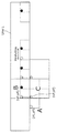
도 18은 상측 블록을 이용하는 경우의 메모리 사용량의 증가를 설명하기 위한 도면이다. 18 is a diagram for explaining an increase in memory usage when the upper block is used.
도면 중의 (xP, yP)은, 블록 C가 포함되는 PredictionUnit(PU: 움직임 예측 단위)의 좌측 상부 화소 위치를 나타낸다. 여기서 블록 C는, 현재의 부호화 대상의 제어 파라미터(예를 들면, skip_flag)를 포함하는 블록이다. 또한, 도면 중의 (xP, yA)은, condition A(상측 블록의 제어 파라미터 skip_flag의 값)로서 이용되는, 블록 B에 포함되는 화소 위치를 나타낸다. 도면 중 (xL, yP)은, condition B(좌측 블록의 제어 파라미터 skip_flag의 값)로서 이용되는, 블록 A에 포함되는 화소 위치를 나타낸다. (XP, yP) in the figure indicates the position of the upper left pixel of the PredictionUnit (PU: motion prediction unit) in which the block C is included. Here, the block C is a block including the control parameter (for example, skip_flag) of the current encoding target. In addition, (xP, yA) in a figure shows the pixel position contained in the block B used as condition A (the value of the control parameter skip_flag of an upper block). In the figure, (xL, yP) represents the pixel position included in the block A used as condition B (the value of the control parameter skip_flag of the left block).
이 경우, 블록 C의 제어 파라미터 skip_flag의 값을 부호화 또는 복호하기 위해서, 부호화 또는 복호 장치는, 상측 블록 B에 포함되는 (xP, yA)의 위치에 대응하는, PU의 skip_flag의 값(또는 조건의 판정 결과)과, 좌측 블록 A에 포함되는 (xL, yP)의 위치에 대응하는, PU의 skip_flag의 값(또는, 조건의 판정 결과)을 유지할 필요가 있다. 여기에서, 이 픽처의 가로폭이 4096픽셀이라고 하면, 1개의 제어 파라미터 skip_flag의 부호화를 위해서, 상측 블록행(도 18에 나타내는 Line L)에 포함되는 모든 판정값을 유지할 필요가 있다. 즉, 1개의 제어 파라미터를 위해서, 4096픽셀÷블록 사이즈의 메모리 용량이 필요해진다. In this case, in order to encode or decode the value of the control parameter skip_flag of the block C, the encoding or decoding apparatus includes a value of the skip_flag of the PU (or conditional value) corresponding to the position of (xP, yA) included in the upper block B. It is necessary to maintain the value of the skip_flag of the PU (or the result of determining the condition) corresponding to the position of (xL, yP) included in the left block A). If the width of this picture is 4096 pixels, it is necessary to hold all determination values contained in the upper block row (Line L shown in Fig. 18) for encoding one control parameter skip_flag. That is, for one control parameter, a memory capacity of 4096 pixels ÷ block size is required.
여기에서, 부호화 대상의 블록 C의 블록 사이즈는 가변이며, 예를 들면, 64×64, 16×16, 또는 4×4 등이다. 또한, (xP, yA)을 포함하는 상측의 행(Line L)에 포함되는 블록의 부호화 또는 복호시에는, 후에 부호화 또는 복호되는 블록 C의 블록 사이즈는 예측할 수 없다. 이는, 부호화 또는 복호 장치는, 상측의 행(블록 A가 포함되는 행)의 부호화 또는 복호의 시점에서는, 그 하측의 행(블록 C가 포함되는 행)의 각 블록의 사이즈를 알 수 없기 때문이다. 따라서, 부호화 또는 복호 장치는, 하측의 행의 블록 사이즈로서, 그 제어 파라미터가 적용되는 블록 사이즈 중 최소의 블록 사이즈가 이용되는 경우를 상정하고, 그 최소의 블록 사이즈마다 제어 파라미터의 값(또는 판정값)을 유지해 두지 않으면 안된다. 또한, 도 18의 검은 원의 위치는, 실제로는 하측의 행(블록 C가 포함되는 행)의 부호화 또는 복호에 있어서는 그 조건값이 필요없음에도 불구하고 유지해 두지 않으면 안되는 조건을 나타낸다. Here, the block size of the block C to be encoded is variable, for example, 64x64, 16x16, 4x4, or the like. In addition, at the time of encoding or decoding a block included in the upper line (Line L) including (xP, yA), the block size of the block C to be encoded or decoded later cannot be predicted. This is because the encoding or decoding apparatus cannot know the size of each block of the lower row (the row containing the block C) at the time of encoding or decoding the upper row (the row containing the block A). . Therefore, the encoding or decoding apparatus assumes the case where the minimum block size among the block sizes to which the control parameter is applied is used as the block size of the lower row, and the value (or determination) of the control parameter for each minimum block size. Value) must be maintained. In addition, the position of the black circle | round | yen of FIG. 18 shows the conditions which must hold | maintain in the encoding or decoding of the lower row | line | column (the line containing block C), although the condition value is unnecessary.
또한, 도 18에 도시하는 인접 2블록(좌측 블록 A와 상측 블록 B)은, H. 264시점의 인접 블록의 개념을 나타내고, 새로운 계층 블록 분할의 관점은 도입되어 있지 않다. 후술하는 대로, HEVC에서 도입이 예정되어 있는 재귀 4분 블록 분할 트리 구조(quad tree partitioning)에 적응한 제어 파라미터에 대해서는, 재귀의 실행순, 계층 깊이, 또는 블록의 위치에 따라, 도 18에서 도시한 참조하는 조건값이 의미가 없는 경우가 있다. In addition, two adjacent blocks (left block A and upper block B) shown in FIG. 18 represent the concept of an adjacent block at H.264 time point, and a new hierarchical block division point of view is not introduced. As will be described later, the control parameters adapted to the recursive four-minute block partitioning tree structure that is to be introduced in HEVC are shown in FIG. 18 according to the execution order of the recursion, the hierarchical depth, or the position of the blocks. Sometimes the condition you refer to is meaningless.
이와 같이, 본 발명자는, 제어 파라미터의 산술 부호화 또는 복호에 있어서 상측 블록의 조건값을 이용함으로써 메모리 사용량이 증가하는 것을 찾아냈다. 또한, 본 발명자는, HEVC에서는 이 메모리 사용량이 더욱 증가하는 것을 찾아냈다. As described above, the inventors have found that the memory usage increases by using the condition value of the upper block in arithmetic coding or decoding of control parameters. In addition, the inventors have found that this memory usage increases further in HEVC.
이에 대하여, 본 발명의 일형태에 관련된 화상 복호 방법은, 산술 복호를 이용하는 화상 복호 방법이며, 복수의 컨택스트 중, 처리 대상 블록에 사용하는 컨택스트를 결정하는 컨택스트 제어 단계와, 제어 파라미터가 산술 부호화됨으로써 얻어진, 상기 처리 대상 블록에 대응하는 비트열을, 결정된 상기 컨택스트를 이용하여 산술 복호함으로써 2치 배열을 복원하는 산술 복호 단계와, 상기 2치 배열을 다치화함으로써 상기 제어 파라미터를 복원하는 다치화 단계를 포함하고, 상기 컨택스트 제어 단계에서는, 상기 처리 대상 블록의 제어 파라미터의 신호 종별을 판정하고, 상기 신호 종별이 제1종별인 경우에, 상기 처리 대상 블록에 인접하는 좌측 블록 및 상측 블록의 복호가 끝난 제어 파라미터를 함께 이용하는 제1 조건을 이용하여 상기 컨택스트를 결정하고, 상기 신호 종별이, 상기 제1 종별과 상이한 제2 종별인 경우에, 상기 상측 블록의 복호가 끝난 제어 파라미터를 이용하지 않는 제2 조건을 이용하여 상기 컨택스트를 결정한다. On the other hand, the image decoding method which concerns on one form of this invention is an image decoding method using arithmetic decoding, The context control step of determining the context used for a process target block among a plurality of contexts, and a control parameter are An arithmetic decoding step of restoring the binary array by arithmetically decoding the bit string corresponding to the processing target block obtained by the arithmetic coding using the determined context; and restoring the control parameter by multiplying the binary array. And a multi-valued step, wherein in the context control step, a signal type of a control parameter of the block to be processed is determined, and when the signal type is a first type, a left block adjacent to the block to be processed and The context is established using a first condition that uses a decoded control parameter of an upper block together. Establish, in the case where the signal type, the first type and a second, different type, using a second condition which does not use the control parameter is decoded in the upper end of the block determines the context.
이에 의하면, 당해 화상 복호 방법은, 메모리 사용량을 삭감할 수 있다. 구체적으로는, 당해 화상 복호 방법은, 제2종별 제어 파라미터에 대해서는 상측 블록의 제어 파라미터를 사용하지 않으므로, 상측 블록의 제2종별 제어 파라미터를 유지할 필요가 없다. 이에 따라, 당해 화상 복호 방법은, 획일적으로 「인접 블록의 제어 파라미터의 값에 의거한 컨택스트 모델을 이용하는」것으로서 좌측 블록과 상측 블록을 이용하는 경우에 비해서 메모리 사용량을 삭감할 수 있다. According to this, the image decoding method can reduce the memory usage. Specifically, since the image decoding method does not use the control parameter of the upper block for the second type control parameter, it is not necessary to hold the second type control parameter of the upper block. Accordingly, the image decoding method can reduce the memory usage as compared with the case of using the left block and the upper block by uniformly "using the context model based on the control parameter value of the adjacent block".
또한, 당해 화상 복호 방법은, 종래의 H. 264에서는 고려되지 않은, 신규 HEVC 특유의 데이터 구조의 계층 트리 구조에 적합한 컨택스트의 이용, 또는, 메모리 참조를 행할 수 있다.In addition, the image decoding method can use a context suitable for a hierarchical tree structure of a new HEVC-specific data structure, which is not considered in the conventional H.264, or perform a memory reference.
또한, 상기 제2 조건은, 상기 상측 블록 및 상기 좌측 블록의 복호가 끝난 제어 파라미터를 함께 이용하지 않는 조건이어도 된다. The second condition may be a condition in which the decoded control parameters of the upper block and the left block are not used together.
이에 의하면, 당해 화상 복호 방법은, 상측 블록에 추가하여, 좌측 블록의 제어 파라미터도 사용하지 않음으로써, 메모리 사용량을 더욱 삭감할 수 있다. According to this, the image decoding method can further reduce the memory usage by not using the control parameters of the left block in addition to the upper block.
또한, 상기 컨택스트 제어 단계에서는, 상기 신호 종별이 상기 제2종별인 경우에, 상기 제2조건으로서, 미리 정해진 컨택스트를 상기 대상 블록의 산술 복호에 사용하는 컨택스트로 결정해도 된다. In the context control step, when the signal type is the second type, as the second condition, a predetermined context may be determined as a contact used for arithmetic decoding of the target block.
이에 의하면, 당해 화상 복호 방법은, 처리량을 저감할 수 있다. According to this, the image decoding method can reduce the throughput.
또한, 상기 신호 종별이 상기 제2종별인 경우에, 상기 제2조건으로서, 상기 처리 대상 블록의 제어 파라미터가 속하는 데이터 단위의 계층 깊이에 따라서 상기 컨택스트를 결정해도 된다. In the case where the signal type is the second type, the context may be determined according to the hierarchical depth of the data unit to which the control parameter of the processing target block belongs as the second condition.
이에 의하면, 당해 화상 복호 방법은, 메모리 사용량을 삭감하면서, 적절한 컨택스트를 선택할 수 있다. According to this, the image decoding method can select an appropriate context while reducing the memory usage.
또한, 상기 컨택스트 제어 단계에서는, 또한, 상기 처리 대상 블록의 위치에 의거하여, 상기 상측 블록의 제어 파라미터를 복호 시에 이용할 수 있는지 여부를 판정하고, 상기 상측 블록의 제어 파라미터를 이용할 수 없는 경우에, 상기 제2조건을 이용하여 상기 컨택스트를 결정해도 된다. In the context control step, further, based on the position of the processing target block, it is determined whether or not the control parameter of the upper block is available at the time of decoding, and when the control parameter of the upper block is not available. In addition, the context may be determined using the second condition.
이에 의하면, 당해 화상 복호 방법은 처리량을 저감할 수 있다. According to this, the image decoding method can reduce the throughput.
또한, 상기 컨택스트 제어 단계에서는, 상기 처리 대상 블록이 슬라이스 경계에 속하는 경우에, 상기 상측 블록의 제어 파라미터를 복호 시에 이용할 수 없다고 판정해도 된다. In the context control step, when the processing target block belongs to a slice boundary, it may be determined that the control parameter of the upper block cannot be used during decoding.
또한, 상기 컨택스트 제어 단계에서는, 상기 처리 대상 블록의 제어 파라미터가 속하는 데이터 단위의 계층 깊이에 따라서 상기 상측 블록의 제어 파라미터를 복호 시에 이용할 수 있는지 여부를 판정해도 된다. In the context control step, it may be determined whether or not the control parameter of the upper block can be used in decoding according to the hierarchical depth of the data unit to which the control parameter of the processing target block belongs.
또한, 상기 제2 종별은, 미리 정해진 데이터 구조를 가지는 제어 파라미터여도 된다. The second type may be a control parameter having a predetermined data structure.
또한, 상기 컨택스트 제어 단계에서는, 또한, 제1 단위의 제어 파라미터의 값에 의거하여, 상기 제1 단위보다 작은 제2 단위의 제어 파라미터에 대하여, 상기 제1조건을 이용하여 상기 컨택스트를 결정할지, 상기 제2 조건을 이용하여 컨택스트를 결정할지를 전환해도 된다. Further, in the context control step, the context is further determined based on the value of the control parameter of the first unit using the first condition for the control parameter of the second unit smaller than the first unit. Whether or not the context is determined using the second condition may be switched.
또한, 상기 제1 종별은, “split_coding_unit_flag”, 또는, “skip_flag”이고, 상기 제2 종별은, “merge_flag”여도 된다. The first type may be "split_coding_unit_flag" or "skip_flag", and the second type may be "merge_flag".
이에 의하면, 당해 화상 복호 방법은, 화상의 BD-rate값 평가 등을 손상시키지 않고, 적절히 제2 종별 제어 파라미터의 메모리 사용량을 삭감할 수 있다. According to this, the image decoding method can appropriately reduce the memory usage of the second type control parameter without damaging the BD-rate value evaluation or the like of the image.
또한, 상기 “split_coding_unit_flag”은, 상기 처리 대상 블록이, 복수의 블록으로 분할되어 있는지 여부를 나타내고, 상기 “skip_flag”은, 상기 처리 대상 블록을 스킵할지 여부를 나타내고, 상기 “merge_flag”은, 상기 처리 대상 블록에 머지 모드를 이용할지 여부를 나타내도 된다. The "split_coding_unit_flag" indicates whether the processing target block is divided into a plurality of blocks, the "skip_flag" indicates whether or not to skip the processing target block, and the "merge_flag" indicates the processing. It may be indicated whether the merge mode is used for the target block.
또한, 상기 화상 복호 방법은, 부호화 신호에 포함되는, 제1 규격 또는 제2 규격을 나타내는 식별자에 따라, 상기 제1규격에 준거한 복호 처리와, 상기 제2 규격에 준거한 복호 처리를 전환하고, 상기 ID가 제1 규격을 나타내는 경우에, 상기 제1 규격에 준거한 복호 처리로서, 상기 컨택스트 제어 단계와, 상기 산술 복호 단계와, 상기 다치화 단계를 행해도 된다. The image decoding method switches between decoding processing based on the first standard and decoding processing based on the second standard in accordance with an identifier indicating a first standard or a second standard included in the coded signal. When the ID indicates the first standard, the context control step, the arithmetic decoding step, and the multiplexing step may be performed as a decoding process based on the first standard.
또한, 본 발명의 일형태에 관련된 화상 부호화 방법은, 산술 부호화를 이용하는 화상 부호화 방법이며, 처리 대상 블록의 제어 파라미터를 2치화함으로써 2치 배열을 생성하는 2치화 단계와, 복수의 컨택스트 중, 상기 처리 대상 블록에 사용하는 컨택스트를 결정하는 컨택스트 제어 단계와, 결정된 상기 컨택스트를 이용하여 상기 2치 배열을 산술 부호화함으로써 비트열을 생성하는 산술 부호화 단계를 포함하고, 상기 컨택스트 제어 단계에서는, 상기 처리 대상 블록의 제어 파라미터의 신호 종별을 판정하고, 상기 신호 종별이 제1 종별인 경우에, 상기 처리 대상 블록에 인접하는 좌측 블록 및 상측 블록의 제어 파라미터를 함께 이용하는 제1 조건을 이용하여 상기 컨택스트를 결정하고, 상기 신호 종별이, 상기 제1 종별과 상이한 제2 종별인 경우에, 상기 상측 블록의 제어 파라미터를 이용하지 않는 제2 조건을 이용하여 상기 컨택스트를 결정한다. Moreover, the image coding method which concerns on one form of this invention is an image coding method using arithmetic coding, The binarization step of generating a binary array by binarizing the control parameter of a process target block, Among a plurality of contexts, A context control step of determining a context to be used for the processing target block; and an arithmetic coding step of generating a bit string by arithmetically encoding the binary array using the determined context. Determines a signal type of a control parameter of the block to be processed, and uses the first condition of using the control parameters of the left block and the upper block adjacent to the block to be processed when the signal type is the first type. To determine the context, and when the signal type is a second type different from the first type, Using a second condition which does not use the control parameter of the upper block to determine the context.
이에 의하면, 당해 화상 부호화 방법은, 메모리 사용량을 삭감할 수 있다. 구체적으로는, 당해 화상 부호화 방법은, 제2 종별 제어 파라미터에 대해서는 상측 블록의 제어 파라미터를 사용하지 않으므로, 상측 블록의 제2 종별의 제어 파라미터를 유지할 필요가 없다. 이에 따라, 당해 화상 부호화 방법은, 획일적으로 「인접 블록의 제어 파라미터의 값에 의거한 컨택스트 모델을 이용하는」것으로서 좌측 블록과 상측 블록을 이용하는 경우에 비해서 메모리 사용량을 삭감할 수 있다. According to this, the image coding method can reduce the memory usage. Specifically, since the image coding method does not use the control parameter of the upper block for the second type control parameter, it is not necessary to hold the control parameter of the second type of the upper block. As a result, the image coding method can reduce the memory usage as compared with the case of using the left block and the upper block by using "a context model based on the control parameter value of the adjacent block" uniformly.
또한, 당해 화상 부호화 방법은, 종래의 H. 264에서는 고려되지 않은, 신규 HEVC 특유의 데이터 구조의 계층 트리 구조에 적합한 컨택스트의 이용, 또는, 메모리 참조를 행할 수 있다. In addition, the picture coding method can use the context suitable for the hierarchical tree structure of the new HEVC-specific data structure, which is not considered in the conventional H.264, or perform a memory reference.
또한, 본 발명의 일형태에 관련된 화상 복호 장치는, 산술 복호를 이용하는 화상 복호 장치이며, 복수의 컨택스트 중, 처리 대상 블록의 산술 복호에 사용하는 컨택스트를 결정하는 컨택스트 제어부와, 제어 파라미터가 산술 부호화됨으로써 얻어진, 상기 처리 대상 블록에 대응하는 비트열을, 결정된 상기 컨택스트를 이용하여 산술 복호함으로써 2치 배열을 복원하는 산술 복호부와, 상기 2치 배열을 다치화함으로써 상기 제어 파라미터를 복원하는 다치화부를 포함하고, 상기 컨택스트 제어부는, 상기 처리 대상 블록의 제어 파라미터의 신호 종별을 판정하고, 상기 신호 종별이 제1 종별인 경우에, 상기 처리 대상 블록에 인접하는 좌측 블록 및 상측 블록의 복호가 끝난 제어 파라미터를 함께 이용하는 제1 조건을 이용하여 상기 컨택스트를 결정하고, 상기 신호 종별이, 상기 제1 종별과 상이한 제2 종별인 경우에, 상기 상측 블록의 복호가 끝난 제어 파라미터를 이용하지 않는 제2 조건을 이용하여 상기 컨택스트를 결정한다. Moreover, the image decoding apparatus which concerns on one form of this invention is an image decoding apparatus using arithmetic decoding, The context control part which determines the context used for arithmetic decoding of a process target block among a plurality of contexts, and a control parameter An arithmetic decoder for restoring a binary array by performing arithmetic decoding on the bit string corresponding to the processing target block obtained by arithmetic coding using the determined context, and multiplying the binary array for the control parameter. And a multi-value conversion unit for restoring, wherein the context control unit determines a signal type of a control parameter of the processing target block, and when the signal type is a first type, a left block and an upper side adjacent to the processing target block. The context is determined using a first condition that uses a decoded control parameter of the block together, When the signal type is a group, the first type and a second, different type, using a second condition which does not use the control parameter is decoded in the upper end of the block determines the context.
이에 의하면, 당해 화상 복호 장치는, 메모리 사용량을 삭감할 수 있다. According to this, the image decoding device can reduce the memory usage.
또한, 본 발명의 일형태에 관련된 화상 부호화 장치는, 산술 부호화를 이용하는 화상 부호화 장치이며, 처리 대상 블록의 제어 파라미터를 2치화함으로써 2치 배열을 생성하는 2치화부와, 복수의 컨택스트 중, 상기 처리 대상 블록에 사용하는 컨택스트를 결정하는 컨택스트 제어부와, 결정된 상기 컨택스트를 이용하여 상기 2치 배열을 산술 부호화함으로써 비트열을 생성하는 산술 부호화부를 포함하고, 상기 컨택스트 제어부는, 상기 처리 대상 블록의 제어 파라미터의 신호 종별을 판정하고, 상기 신호 종별이 제1종별인 경우에, 상기 처리 대상 블록에 인접하는 좌측 블록 및 상측 블록의 제어 파라미터를 함께 이용하는 제1 조건을 이용하여 상기 컨택스트를 결정하고, 상기 신호 종별이, 상기 제1 종별과 상이한 제2 종별인 경우에, 상기 상측 블록의 제어 파라미터를 이용하지 않는 제2 조건을 이용하여 상기 컨택스트를 결정한다. Moreover, the image coding apparatus which concerns on one form of this invention is an image coding apparatus which uses arithmetic coding, The binarization part which produces a binary array by binarizing the control parameter of a process target block, Among a plurality of contexts, And a context controller configured to determine a context to be used for the processing target block, and an arithmetic encoder to generate a bit string by performing arithmetic coding on the binary array using the determined context. The signal type of the control parameter of the block to be processed is determined, and when the signal type is the first type, the contact is made using a first condition that uses the control parameters of the left block and the upper block adjacent to the block to be processed together. Is determined, and when the signal type is a second type different from the first type, The context is determined using a second condition that does not use a parameter.
이에 의하면, 당해 화상 부호화 장치는, 메모리 사용량을 삭감할 수 있다. As a result, the picture coding apparatus can reduce the memory usage.
또한, 본 발명의 일형태에 관련된 화상 부호화 복호 장치는, 상기 화상 복호 장치와, 상기 화상 부호화 장치를 포함한다. Moreover, the image coding decoding apparatus which concerns on one form of this invention contains the said image decoding apparatus and the said image coding apparatus.
또한, 이들 전반적 또는 구체적인 양태는, 시스템, 방법, 집적 회로, 컴퓨터 프로그램 또는 기록 매체로 실현되어도 되고, 시스템, 방법, 집적 회로, 컴퓨터 프로그램 및 기록 매체의 임의 조합으로 실현되어도 된다. In addition, these general or specific aspects may be implemented by a system, a method, an integrated circuit, a computer program, or a recording medium, and may be implemented by any combination of a system, a method, an integrated circuit, a computer program, and a recording medium.
이하, 본 발명의 일양태에 관련된 화상 복호 장치 및 화상 부호화 장치에 대하여, 도면을 참조하면서 구체적으로 설명한다. EMBODIMENT OF THE INVENTION Hereinafter, the image decoding apparatus and image encoding apparatus which concern on one aspect of this invention are demonstrated concretely, referring drawings.
또한, 이하에서 설명하는 실시의 형태는, 모두 본 발명의 일구체적 예를 나타내는 것이다. 이하의 실시 형태에서 나타내는 수치, 형상, 재료, 구성 요소, 구성 요소의 배치 위치 및 접속 형태, 단계, 단계의 순서 등은 일예이며, 본 발명을 한정하는 주지가 아니다. 또한, 이하의 실시 형태에 있어서의 구성 요소 중, 최상위 개념을 나타내는 독립 청구항에 기재되지 않은 구성 요소에 대해서는, 임의의 구성 요소로서 설명된다. In addition, all the embodiment demonstrated below shows one specific example of this invention. The numerical values, shapes, materials, components, arrangement positions and connection forms of the components, the steps, the order of the steps, and the like shown in the following embodiments are examples and are not intended to limit the present invention. In addition, the component which is not described in the independent claim which shows the highest concept among the components in the following embodiment is demonstrated as arbitrary components.
(실시의 형태 1)(Embodiment 1)
이하, 본 발명의 실시 형태 1에 관련된 화상 부호화 장치에 대하여 설명한다. 본 발명의 실시 형태 1에 관련된 화상 부호화 장치는, 산술 부호화에 있어서, 제어 파라미터의 신호 종별에 따라, (1) 상측 블록을 이용하여 컨택스트를 결정할지, (2) 상측 블록을 이용하지 않고 컨택스트를 결정할지를 전환한다. 이에 따라, 화질의 열화를 억제하면서, 메모리 사용량을 삭감할 수 있다. Hereinafter, the picture coding apparatus according to the first embodiment of the present invention will be described. In the arithmetic coding, according to the first embodiment of the present invention, in the arithmetic coding, according to the signal type of the control parameter, (1) the context is determined using the upper block, or (2) the contact is not used without the upper block. Switch whether to determine the test. Thereby, the memory usage can be reduced while suppressing deterioration of image quality.
먼저, 본 발명의 실시 형태 1에 관련된 화상 부호화 장치의 구성을 설명한다. First, the configuration of the picture coding apparatus according to the first embodiment of the present invention will be described.
도 1은 본 실시의 형태에 관련된 화상 부호화 장치(100)의 블록도이다. 1 is a block diagram of a
도 1에 도시하는 화상 부호화 장치(100)는, 산술 부호화를 이용하는 화상 부호화 장치이며, 입력 화상 신호(121)를 부호화함으로써 비트 스트림(124)을 생성한다. 이 화상 부호화 장치(100)는, 제어부(101)와, 차분부(102)와, 변환 및 양자화부(103)와, 가변 길이 부호화부(104)와, 역양자화 및 역변환부(105)와, 가산부(106)와, 화면내 예측부(107)와, 화면간 예측부(108)와, 스위치(109)를 포함한다. The
제어부(101)는, 부호화 대상의 입력 화상 신호(121)에 의거하여 제어 파라미터(130)를 산출한다. 예를 들면, 제어 파라미터(130)는, 부호화 대상의 입력 화상 신호(121)의 픽처 타입을 나타내는 정보, 부호화 대상 블록의 움직임 예측 단위(Prediction Unit PU)의 사이즈, 및, 움직임 예측 단위의 제어 정보 등을 포함한다. 여기서 제어 파라미터(130)(Control data)는 그 자신이 부호화 대상이 된다. 따라서, 제어부(101)는, 이 제어 파라미터(130)를, 가변 길이 부호화부(104)에 출력한다. The
차분부(102)는, 블록 단위의 입력 화상 신호(121)와 예측 화상 신호(129)의 차분값(잔차값)인 잔차 신호(122)를 산출한다. The
변환 및 양자화부(103)는, 잔차 신호(122)를 주파수 계수치로 변환하고, 얻어진 주파수 계수치를 양자화함으로써 양자화 변환 계수(123)(residual data)를 생성한다. The transform and
역양자화 및 역변환부(105)는, 양자화 변환 계수(123)를 주파수 계수치로 역양자화하고, 얻어진 주파수 계수치를 역변환함으로써, 복원된 잔차 신호(125)를 생성한다. The inverse quantization and
가산부(106)는, 잔차 신호(125)와 예측 화상 신호(129)를 가산함으로써 복원 화상 신호(126)를 출력한다. The
화면내 예측부(107)는, 복원 화상 신호(126)를 이용하여 화면내 예측 처리를 행함으로써 예측 화상 신호(127)를 생성한다. 화면간 예측부(108)는, 복원 화상 신호(126)를 이용하여 화면간 예측 처리를 행함으로써 예측 화상 신호(128)를 생성한다. The
스위치(109)는, 예측 화상 신호(127) 및 예측 화상 신호(128)의 한쪽을 선택하고, 선택한 신호를 예측 화상 신호(129)로서 출력한다. The
가변 길이 부호화부(104)는, 입력된 블록마다 양자화 변환 계수(123) 및 제어 파라미터(130)를, 전술의 CABAC을 이용하여 부호화함으로써 비트 스트림(124)을 생성한다. The
다음에, 가변 길이 부호화부(104)의 구성을 설명한다. Next, the structure of the variable
도 2는, 가변 길이 부호화부(104)의 기능 블록도이다. 가변 길이 부호화부(104)는, 2치화부(141)와, 컨택스트 제어부(142)와, 2치 산술 부호화부(143)를 포함한다. 이하, 제어 파라미터(130)의 가변 길이 부호화 처리에 대하여 설명한다. 또한, 양자화 변환 계수(123)의 가변 길이 부호화 처리에 대해서는 설명을 생략하는데, 예를 들면, 기지의 기술을 이용하여 실현할 수 있다. 2 is a functional block diagram of the
2치화부(141)는, 제어 파라미터(130)를 2치화함으로써 2치 배열(151)을 생성한다. 구체적으로는, 2치화부(141)는, 비특허 문헌 1에 있어서의 II. 1) binarizaion 처리를 실행하는 처리부이다. 이 2치화부(141)는, 제어 파라미터(130)를 신호 종별마다 사전에 정해진 2치화 처리 방법에 의해 bin string이라고 불리는 2치 배열(151)로 변환한다. 또한, 신호 종별과 2치화 처리 방법의 대응에 대해서는 후술한다. 또한, 2치화부(141)는, 입력된 제어 파라미터(130)가 flag 등의 1바이너리치인 경우는, 당해 제어 파라미터(130)를 그대로 2치 배열(151)로서 출력한다. The
컨택스트 제어부(142)는, 복수의 컨택스트(확률 상태 테이블) 중, 처리 대상의 블록에 포함되는 제어 파라미터(130)의 산술 부호화에 사용하는 컨택스트를 결정한다. 또한, 컨택스트 제어부(142)는, 결정한 컨택스트를 지정하는 컨택스트 인덱스(152)를 2치 산술 부호화부(143)에 출력한다. The
구체적으로는, 컨택스트 제어부(142)는, 비특허 문헌 1에 있어서의 2) context modeling 처리를 실행하는 처리부이다. 이 컨택스트 제어부(142)에는, 2치 산술 부호화부(143)가 출력한 2치 배열(151)에 포함되는 복수의 요소가 순차적으로 입력된다. 컨택스트 제어부(142)는, 제어 파라미터(130)의 신호 종별과 이 바이너리의 2치 배열(151) 중의 요소 위치에 따라, 복수의 컨택스트 중, 이 바이너리에 사용하는 컨택스트를 선택하고, 선택한 컨택스트를 나타내는 인덱스인 컨택스트 인덱스(152)를 2치 산술 부호화부(143)에 출력한다. Specifically, the
또한, 컨택스트 제어부(142)는, 컨택스트의 상태로서, 제어 파라미터(130)의 2치 배열의 각각의 요소를 다시 조건부 확률의 조건으로 상세 구분화한 수(소위 컨택스트 인덱스수)의 확률 상태 테이블을 유지하고 있고, 이 확률 상태 테이블을 초기화 및 갱신한다. In addition, the
또한, 컨택스트 제어부(142)는, 신호 종별마다(2치 배열의 요소수가 2이상인 경우는, 제어 파라미터(130)의 2치 배열의 요소 번호마다를 말한다. 이하 동일)에 더욱 상세 구분으로서 발생 조건 τ마다(컨택스트마다)의 상태(probability state index)를 유지한다. 이 상태는, 「0」 또는 「1」의 2값 중, 확률이 낮은 쪽의 발생 확률 P(내분 비율: 전형적으로는 6bit의 값)와, 확률이 높은 쪽이 어느 쪽인지를 나타내는 값(1bit)의 합계 7bit값이다. 또한, 상태를 유지한다는 것은 초기화 및 갱신하는 것이다. 예를 들면, 갱신 처리란, H264과 마찬가지로 64개의 유한 상태간의 천이이며, 지금 어느 확률 상태 probability state(즉 어느 확률)에 있는지의 indexing을 변경하는 것이다. In addition, the
구체적으로는, 컨택스트 제어부(142)는, 2치 중 확률이 높은 most probable측의 사상 X가 발생한 경우는, most probable측인 확률의 비율을 조금 증가시킨다. 예를 들면, 컨택스트 제어부(142)는, 64개의 테이블에 대응하는 확률 인덱스(probability state index)의 값을 1증감시킴으로써, most probable측인 확률의 비율을 조금 증가시킬 수 있다. 한편, (예측된 확률에 반하여) 확률이 낮은 쪽의 사상 not X가 발생한 경우에는, 컨택스트 제어부(142)는, 유지하고 있는 most probable의 확률의 비율을 크게, 소정의 스케일 계수 α (예를 들면 ≒ 0.95)에 의거하여 감소시킨다(비특허 문헌 1, Fig 6을 참조). 본 실시의 형태의 컨택스트 제어부(142)는, H. 264과 동일하게, 이 α을 고려한 변경에 대응하도록, 대응된 테이블 인덱스의 변경값에 의거하여 상태를 천이시켜 유지하고 있다. Specifically, the
2치 산술 부호화부(143)는, 컨택스트 제어부(142)에서 결정된 컨택스트를 이용하여 2치 배열(151)을 산술 부호화함으로써 비트 스트림(124)(비트열)을 생성한다. The binary
구체적으로는, 2치 산술 부호화부(143)는, 비특허 문헌 1에 있어서의 3) binary arithmetic coding 처리를 실행하는 처리부이다. 이 2치 산술 부호화부(143)는, 컨택스트 인덱스(152)로 지정되는 컨택스트를 이용하여, 2치 배열(151)을 산술 부호화함으로써 비트 스트림(124)을 생성한다. 여기서 산술 부호화란, 다양한 신호 종별의 제어 파라미터(130)에 대하여 발생한 사상을 확률의 누적으로서 취급하여, 어떤 사상이 일어났는지를 1개의 수직선 상의 소정 범위로 범위를 좁히면서 대응시키는 것이라고 할 수 있다. Specifically, the binary
먼저, 2치 산술 부호화부(143)는, 1개의 수직선을, 컨택스트 제어부(142)로부터 주어진, 바이너리가 취할 수 있는 2개의 값의 발생 확률에 따라서 2개의 반구간으로 내분한다. 실제로 발생한 바이너리의 값(예를 들면 「0」)이, 높은 확률(0.5를 초과하는 확률(예를 들면 0.75))측의 값인 경우에는, 2치 산술 부호화부(143)는, 수직선 중의 범위의 하한치(low)를 변경하지 않고 유지하고, 금회의 확률 0.75에, 스케일 계수 0.95를 1회 곱한 결과에 대응하는 값을 새로운 폭(Range)에 설정한다. 한편, 실제로 발생한 바이너리의 값이, 예측된 낮은 확률측의 값인 경우에는, 2치 산술 부호화부(143)는, 범위의 하한값(low)을, 높은 쪽의 확률만큼 이동시켜, 폭(Range)을 낮은 쪽의 확률에 따라서 변경시킨다. 이와 같이, 확률폭(Range)의 곱셈 결과의 누적에 의해 구간을 유지하는데, 확률이 낮은 쪽의 값이 연속하여 발생한 경우에는 폭(Range)의 길이가 연산으로 확보할 수 있는 정밀도 이하가 된다. 이 경우, 2치 산술 부호화부(143)는, 정밀도를 유지하기 위해서 폭(Range)을 확대하는 처리(renorm)를 행함과 더불어 현 시점의 범위를 나타내기 위한 비트열을 출력한다. 반대로, 확률이 높은 쪽(0.95 등)의 값이 연속하여 발생한 경우에는, 이 확률값을 곱셈했다고 해도 폭(Range)의 길이가 소정의 길이보다 짧아질때까지 몇회나 이 연산(표에 의한 실장의 경우는 상태 천이)을 행할 수 있다. 따라서 이 경우는 비트를 출력할때까지 누적할 수 있는 심볼수가 많아진다. First, the binary
도 3은, 인접 블록의 제어 파라미터(130)의 값에 의거하는 컨택스트 모델을 이용하는 제어 파라미터(130)를 정리한 표이다. 3 is a table summarizing the
좌측으로부터 열의 의미를 설명한다. The meaning of a column is demonstrated from the left side.
(c2) 신호 종별(syntax element)은, 제어 파라미터(130)의 신호 종별의 구체적 명칭을 나타낸다. 또한, 각 신호 종별의 의미는 후술한다. (c2) A signal type indicates a specific name of the signal type of the
(c3) 2치화 방식(binarization scheme)은, 직좌의 열로 지정되는 제어 파라미터(130)(SE)에 적용되는 2치화 방식을 나타낸다. 또한, 2치화 처리는, 상기 2치화부(141)에서 실행된다. 또한, 난 중 「고정 길이」란, 2치화부(141)가, 직접 좌측의 제어 파라미터(130)의 값을 고정 길이(Fixed Length)의 2치 배열(bin string)로 출력하는 것을 의미한다. HEVC에 있어서 신호 종별명이 “flag”로 끝나는 신호 종별의 제어 파라미터(130)는, 「0」 또는 「1」중 어느 하나의 값을 취하는 1바이너리치이다. 따라서, 2치화부(141)가 출력하는 2치 배열(151)의 요소는, 제1번째의 요소(binIdx=0)만이며, 제2번째 이후의 요소(binIdx>=1의 요소는 출력하지 않는다. 즉, 2치화부(141)는, 제어 파라미터(130)의 값을 그대로 2치 배열(151)로서 출력한다. (c3) The binarization scheme indicates a binarization scheme applied to the control parameter 130 (SE) designated by the column of the rectum. In addition, the binarization processing is performed by the
또한, 난 중 「가변 길이」란, 2치화부(141)가, 제어 파라미터(130)의 값을, 그 값의 발생 빈도순으로 짧은 바이너리 길이가 되도록 대응시킨 가변 길이의 바이너리열(bin string, 또는, 2치 배열이며 요소수≥1)을 이용하여, 2치 배열화하여 출력하는 것을 나타낸다. 예를 들면, 2치화부(141)는, (Truncated) Unary형, 또는 Unary형과 다른 지수의 Golomb 방식 등의 복수 방식의 조합 등의, 신호 종별에 대응한 방식을 이용하여 출력한다(비특허 문헌 1, A. Binarization을 참조). 또한, 가변 길이의 경우, 2치 배열(151)의 배열 요소는 1개인 경우도 있지만, 2개 이상이 될 수도 있다. 또한, 후술하는 화상 복호 장치의 다치화부에서는, 이 2치화 방식의 역변환을 행함으로써, 입력된 2치 배열을 다치 또는 플래그값으로 복원한다. In addition, the term "variable length" means a variable length binary string in which the
(c4) 제1번째 요소(binIdx=0) 컨택스트 인덱스는, 컨택스트 제어부(142)가, c3의 난에서 지정된 2치화 방식에 의해 생성된 바이너리 배열에 포함되는 1번째의 요소에 대하여 적용하는 컨택스트 인덱스(증분값)의 선택 사항을 나타낸다. 난 중에 「0, 1, 2」로 기재되어 있는 경우, 컨택스트 제어부(142)는, 3개의 확률 상태 테이블(컨택스트)로부터 1개의 확률 상태 테이블을 선택하여 적용하는 것을 의미한다. 예를 들면, 신호 종별 “skip_flag”에 대해서는, 이 1개의 신호 종별에 대하여, 조건으로 세분화한 컨택스트 인덱스를 3개 준비하고, 즉, 컨택스트를 3개 준비하여 산술 부호화를 행하는 것을 의미한다. (c4) The first element (binIdx = 0) context index is applied by the
마찬가지로, c4란 중에 「0, 1, 2, 3」으로 기재되어 있는 경우, c2란에서 지정되는 신호 종별의 제어 파라미터(130)의 값을, c3란의 2치화 방식에 의해 2치 배열화된 2치 배열(151)에 포함되는 제1 요소(binIdx=0)에 적용되는 컨택스트가 0, 1, 2, 또는, 3의 4개 중 택일인 것을 의미한다. 또한, 난 중의 조건식에 대해서는 후술한다. Similarly, when it is described as "0, 1, 2, 3" in the c4 column, the value of the
(c5) 좌측 블록 조건 L(condL)은, 컨택스트 제어부(142)가, 칼럼 c4에 있어서 0, 1, 2의 값 중 어느 하나의 값을 선택하기 위한 좌측 블록의 조건(condition)을 나타낸다. 이 조건은, 부호화 대상(또는 복호 대상)의 제어 파라미터에 대응하는, 좌측 블록의 제어 파라미터의 값에 따라서 결정되는 true 또는 false의 값을 취한다. (c5) The left block condition L (condL) indicates the condition of the left block for the
예를 들면, 제어 파라미터(SE)가 skip_flag인 경우에는, skip_flag[xL][yL]의 값이 true(예를 들면 「1」)이면 true가, false(예를 들면 「0」)이면 false가 출력된다. For example, if the control parameter SE is skip_flag, true if the value of skip_flag [xL] [yL] is true (for example, "1"), and false if false (for example, "0"). Is output.
(c6) 상측 블록 조건 A(condA)는, 컨택스트 제어부(142)가, 칼럼 c4로 지정된 배열 요소의 부호화 및 복호에 있어서 0, 1, 2의 값 중 어느 하나의 값을 선택하기 위한 상측 블록의 조건(Condition)을 나타낸다. 이 조건은, 부호화 대상(또는 복호 대상)의 제어 파라미터에 대응하는, 상측 블록의 제어 파라미터의 값에 따라서 결정되는 true 또는 false의 값을 취한다. 예를 들면, 제어 파라미터(SE)가 skip_flag인 경우에는, skip_flag[xA][yA]의 값이 true(예를 들면 「1」)이면 true가, false (예를 들면 「0」)이면 false가 출력된다. (c6) The upper block condition A (condA) is an upper block for the
또한, 도시하지 않지만, 2비트 이상의 신호 종별에는 (c7)「binIdx>=1에 적용하는 컨택스트 증분값」이 대응되어 있다. 이 (c7)은, 컨택스트 제어부(142)가, 2치 배열의 2요소째 이후의 바이너리(binIdx>=1의 인덱스값을 가지는 바이너리 배열 요소의 바이너리값)에 적용하는 컨택스트 모델을 나타낸다. Although not shown, (c7) "Context increment value applied to binIdx> = 1" corresponds to the signal type of two bits or more. This (c7) shows the context model that the
본 실시의 형태에 관련된 화상 부호화 방법은, 상기 좌측 블록 조건 L 및 상측 블록 조건 A에 대하여 제어 파라미터(130)의 신호 종별에 따라서 이하의 동작을 전환한다(상이한 패턴을 이용하여 동작한다). In the picture coding method according to the present embodiment, the following operations are switched (the operation is performed using different patterns) with respect to the left block condition L and the upper block condition A in accordance with the signal type of the
(패턴 1) 2개의 인접 블록(좌측 블록 조건 L의 판정값과 상측 블록 조건 A의 판정값)을 사용한다. (Pattern 1) Two adjacent blocks (the determination value of the left block condition L and the determination value of the upper block condition A) are used.
(패턴 2) 1개의 인접 블록(좌측 블록 조건 L의 판정값만)을 사용한다. (Pattern 2) One adjacent block (only the determination value of the left block condition L) is used.
(패턴 3) 0개의 인접 블록을 사용한다(좌측 블록 조건 L도 상측 블록 조건 A도 사용하지 않는다). (Pattern 3) 0 adjacent blocks are used (neither the left block condition L nor the upper block condition A is used).
도 4는, 도 2에 도시하는 가변 길이 부호화부(104)가 실행하는 본 실시의 형태에 관련된 화상 부호화 방법을 나타내는 플로우도이다. FIG. 4 is a flowchart showing an image coding method according to the present embodiment executed by the variable
우선, 2치화부(141)는 제어 파라미터(130)의 값을, 이 제어 파라미터(130)의 신호 종별에 대응하는 방식으로 2치 배열화한다(S101). First, the
다음에, 컨택스트 제어부(142)는, 이 제어 파라미터(130)의 산술 부호화에 이용하는 컨택스트의 기본값을 취득한다(S102). 예를 들면, 컨택스트 제어부(142)는, 픽처 타입(I, P, B)에 따라서 이 기본값을 결정한다. Next, the
다음에, 컨택스트 제어부(142)는, 제어 파라미터(130)의 신호 종별에 따라, 상기 패턴 1∼패턴 3 중 어느 하나를 이용하여 컨택스트값을 결정한다(S103). 여기에서, 컨택스트값을 결정한다는 것은, 컨택스트의 기본값에 대한 조정치(인크리먼트값 CtxIdxInc)을 결정하는 것과 등가이다. Next, the
먼저, 컨택스트 제어부(142)는, 제어 파라미터(130)의 신호 종별을 판별한다(S103). 제어 파라미터(130)의 신호 종별이 패턴 1에 대응하는 제1종별인 경우(S104에서 제1종별), 컨택스트 제어부(142)는, 인접하는 2개의 블록(블록 A와 블록 B)의 각각의 제어 파라미터의 값으로부터 도출된 판정값을 이용하여 컨택스트값을 결정한다(S105). 바꿔 말하면, 컨택스트 제어부(142)는, 좌측 블록 및 상측 블록의 2개의 인접 블록의 제어 파라미터를 이용하는 조건을 이용하여 컨택스트를 결정한다. 이 경우, 컨택스트 제어부(142)는, 도 3에 도시하는 (c5)CondL의 판정 결과와 (c6)condA의 판정 결과의 양쪽의 값을 이용한다. 따라서, 제1종별의 제어 파라미터에 대해서는 픽처의 가로 일렬분의 데이터를 보유하게 된다. First, the
한편으로, 제어 파라미터(130)의 신호 종별이 패턴 2에 대응하는 제2 종별인 경우(S104에서 제2 종별), 컨택스트 제어부(142)는, 1개의 인접 블록(부호화순으로 가장 가까운 인접 블록)의 제어 파라미터의 값을 이용하여 컨택스트값을 결정한다(S106). 바꿔 말하면, 컨택스트 제어부(142)는, 상측 블록의 제어 파라미터를 이용하지 않는 조건을 이용하여 컨택스트를 결정한다. On the other hand, when the signal type of the
한편으로, 제어 파라미터(130)의 신호 종별이 패턴 3에 대응하는 제3 종별인 경우(S104에서 제3 종별), 컨택스트 제어부(142)는, 상측 블록 및 좌측 블록의 제어 파라미터를 함께 이용하지 않고, 고정적으로 컨택스트값을 결정한다(S107). On the other hand, when the signal type of the
다음에, 컨택스트 제어부(142)는, 단계 S102에서 결정된 컨택스트의 기본값에, 단계 S103에서 결정된 증분값을 가산함으로써 컨택스트 인덱스의 값을 도출한다(S108). Next, the
마지막에, 2치 산술 부호화부(143)는, 제1요소의 바이너리값을, 단계 S108에서 결정된 컨택스트 인덱스값으로 지정되는 컨택스트값을 이용하여 산술 부호화함으로써, 비트열(비트 스트림(124))을 생성한다(S109). Finally, the binary
다음에, 2치배열에 포함되는 모든 요소에 대하여 단계 S102∼S109의 처리 실행이 완료하지 않은 경우(S110에서 NO), 가변 길이 부호화부(104)는, 2치 배열에 포함되는 다음 요소에 대하여, 단계 S102∼S109의 처리를 실행한다. 한편, 2치 배열에 포함되는 모든 요소에 대하여 단계 S102∼S109의 처리 실행이 완료된 경우(S110에서 YES), 가변 길이 부호화부(104)는, 처리 대상 블록의 제어 파라미터에 대한 부호화 처리를 종료한다. Next, when the processing execution of steps S102 to S109 has not been completed for all elements included in the binary array (NO in S110), the variable
이상과 같이, 본 실시의 형태에 관련된 화상 부호화 장치(100)는, 산술 부호화에 있어서, 제1종별의 제어 파라미터에 대해서는, 상측 블록을 이용하여 컨택스트를 결정하고, 제2종별 및 제3종별의 제어 파라미터에 대해서는, 상측 블록을 이용하지 않고 컨택스트를 결정한다.As described above, in the arithmetic coding, the
이 구성에 의해, 당해 화상 부호화 장치(100)는, 획일적으로 「인접 블록의 제어 파라미터의 값에 의거한 컨택스트 모델을 이용하는」것으로서 좌측 블록과 상측 블록을 이용하는 경우에 비해서 메모리 사용량을 삭감할 수 있다. 이에 따라, 당해 화상 부호화 장치(100)는, 화질의 열화를 억제하면서, 메모리 사용량을 삭감할 수 있다. With this configuration, the
(실시의 형태 2)(Embodiment 2)
본 실시의 형태에서는, 상기 화상 부호화 장치(100)에 의해 생성된 비트 스트림(124)을 복호하는 화상 복호장치에 대하여 설명한다. In the present embodiment, an image decoding apparatus for decoding the
도 5는, 본 실시의 형태에 관련된 화상 복호 장치(200)의 블록도이다. 이 화상 복호 장치(200)는, 산술 복호를 이용하는 화상 복호 장치이며, 비트 스트림(124)을 복호함으로써 화상 신호(229)를 생성한다. 여기서 비트 스트림(124)은, 예를 들면, 상술한 화상 부호화 장치(100)에 의해 생성된 비트 스트림(124)이다. 5 is a block diagram of the
화상 복호 장치(200)는, 제어부(201)와, 가변 길이 복호부(202)와, 역양자화부(204)와, 역변환부(205)와, 가산부(206)와, 화면내 예측부(207)와, 화면간 예측부(208)를 포함한다. The
화상 복호 장치(200)는, 소정의 처리 단위의 부호열마다 복호 처리를 행한다. 여기서 처리 단위는, 예를 들면, 슬라이스 단위, 또는 블록 단위이다. The
가변 길이 복호부(202)는, 비트 스트림(124)에 산술 복호를 행함으로써, 제어 파라미터(230)(control data syntax element)와, 양자화 변환 계수(223)(Residual data syntax element값)를 생성한다. 생성된 제어 파라미터(230)는 제어부(201)에 출력된다. The variable
제어부(201)는, 제어 파라미터(230)에 따라서 화상 복호 장치(200)에 포함되는 처리부를 제어한다. The
역양자화부(204)는, 양자화 변환 계수(223)를 역양자화함으로써 직교 변환 계수(224)를 생성한다.
역변환부(205)는, 직교 변환 계수(224)를 역변환함으로써 잔차 신호(225)를 복원한다. 가산부(206)는 잔차 신호(225)와 예측 화상 신호(화상 신호(229))를 가산함으로써 복호 화상 신호(226)를 생성한다. The
화면내 예측부(207)는, 복호 화상 신호(226)를 이용하여 화면내 예측 처리를 행함으로써 예측 화상 신호(227)를 생성한다. 화면간 예측부(208)는, 복호 화상 신호(226)를 이용하여 화면간 예측 처리를 행함으로써 예측 화상 신호(228)를 생성한다. The
스위치(209)는, 예측 화상 신호(227) 및 예측 화상 신호(228)의 한쪽을 선택하고, 선택한 신호를 화상 신호(229)(예측 화상 신호)로서 출력한다. The
다음에, 가변 길이 복호부(202)의 구성을 설명한다. Next, the configuration of the variable
도 6은, 가변 길이 복호부(202)의 구성을 나타내는 기능 블록도이다. 가변 길이 복호부(202)는, 2치 산술 복호부(243)와, 컨택스트 제어부(242)와, 다치화부(241)를 포함한다. 이하, 제어 파라미터(230)의 가변 길이 복호 처리에 대하여 설명한다. 또한, 양자화 변환 계수(223)의 가변 길이 복호 처리에 대해서는 설명을 생략하는데, 예를 들면, 기지의 기술을 이용하여 실현할 수 있다. 6 is a functional block diagram showing the configuration of the variable
컨택스트 제어부(242)는, 복수의 컨택스트 중, 처리 대상의 블록 제어 파라미터(230)의 산술 복호에 사용하는 컨택스트를 결정한다. 또한, 컨택스트 제어부(242)는, 결정한 컨택스트를 지정하는 컨택스트 인덱스(252)를 2치 산술 복호부(243)에 출력한다. The
구체적으로, 컨택스트 제어부(242)는, 유지하는 확률 천이 모델로서, 도 2에 도시하는 컨택스트 제어부(142)와 동일한 컨택스트 모델을 이용한다. 2치 산술 부호화부(143)가 64개의 확률 상태를 이용하는 경우는, 2치 산술 복호부(243)도 64개의 확률 상태를 가진다. 이는, 부호화되는 수직선 상의 레인지를, 부호화측 및 복호측의 양쪽에서 완전히 동일하게 해석할 필요가 있기 때문이다. 따라서, 부호화측이, 상술한 패턴 1∼3의 3개의 패턴에서 선택한 패턴과, 동일한 패턴을 복호 장치측에서도 이용한다. Specifically, the
2치 산술 복호부(243)는, 컨택스트 제어부(242)에서 결정된 컨택스트를 이용하여 비트열(비트 스트림(124))을 산술 복호함으로써 2치 배열(251)을 복원한다. 구체적으로, 2치 산술 복호부(243)는, 컨택스트 제어부(242)로부터 주어진 컨택스트 인덱스에 의해 지정되는 컨택스트(확률 상태 테이블)를 이용하여, 입력된 비트열을 2치 배열(251)로 복원한다. The binary
다치화부(241)는, 2치 배열(251)을 필요하면 다치화함으로써 제어 파라미터(230)에 복원한다. 이와 같이, 화상 부호화 장치(100)가 구비하는 컨택스트 제어부(142)와, 화상 복호 장치(200)가 구비하는 컨택스트 제어부(242)는, 어떤 신호 종별의 제어 파라미터의 산술 부호화 및 산술 복호시에 쌍방에서 동일한 컨택스트 모델을 이용한다. The
도 7은 가변 길이 복호부(202)가 실행하는 본 실시의 형태에 관련된 화상 복호 방법을 나타내는 플로우도이다. 7 is a flowchart showing an image decoding method according to the present embodiment executed by the variable
먼저, 가변 길이 복호부(202)는 비트 스트림(124)을 취득한다(S201). First, the variable
다음에, 컨택스트 제어부(242)는, 비트 스트림(124)의 데이터 구조에 따라서 복호 대상의 제어 파라미터의 신호 종별을 결정한다(S202). Next, the
다음에, 컨택스트 제어부(242)는, 복호 대상의 제어 파라미터의 산술 복호에 이용하는 컨택스트의 기본값을 결정한다(S203). 예를 들면, 컨택스트 제어부(242)는, 픽처 타입(I, P, B)에 따라서 이 기본값을 결정한다. Next, the
다음에, 컨택스트 제어부(242)는, 제어 파라미터의 신호 종별에 따라, 상기 패턴 1∼패턴 3중 어느 하나를 이용하여 컨택스트값을 결정한다(S204). 여기에서, 컨택스트값을 결정한다는 것은, 컨택스트의 기본값에 대한 조정치(인크리먼트치 CtxIdxInc)를 결정하는 것과 등가이다. 예를 들면, 컨택스트 제어부(242)는, 제어 파라미터의 신호 종별에 따라서 패턴 1∼패턴 3 중 어느 것을 이용할지의 판단을, 정적으로 사전에 결정된 표에 따라 행한다. Next, the
컨택스트 제어부(242)는, 2치 배열(251)에 포함되는 제1요소의 바이너리의 값을 산술 복호에 의해 얻기 위해서 이용하는 컨택스트의 결정에 이용하는 인접 블록을, 제어 파라미터의 신호 종별에 따라서 전환한다. The
먼저, 컨택스트 제어부(242)는, 제어 파라미터(230)의 신호 종별을 판정한다(S205). 신호 종별이 패턴 1에 대응하는 제1종별인 경우(S205에서 제1종별), 컨택스트 제어부(242)는, 인접하는 2개의 블록의 각각의 제어 파라미터를 이용하여 컨택스트값을 결정한다(S206). 바꿔 말하면, 컨택스트 제어부(242)는, 좌측 블록 및 상측 블록에 2개의 인접 블록의 복호가 끝난 제어 파라미터를 이용하는 조건을 이용하여 컨택스트를 결정한다. First, the
한편, 신호 종별이 패턴 2에 대응하는 제2 종별인 경우(S205에서 제2 종별), 컨택스트 제어부(242)는, 1개의 인접 블록(부호화순으로 가장 가까운 인접 블록)의 제어 파라미터의 값을 이용하여 컨택스트값을 결정한다(S207). 바꿔 말하면, 컨택스트 제어부(242)는, 상측 블록의 복호가 끝난 제어 파라미터를 이용하지 않는 조건을 이용하여 컨택스트를 결정한다. On the other hand, when the signal type is the second type corresponding to the pattern 2 (the second type in S205), the
한편, 신호 종별이 패턴 3에 대응하는 제3종별인 경우(S205에서 제3종별), 컨택스트 제어부(242)는, 고정적으로 컨택스트값을 결정한다(S208). 바꿔 말하면, 컨택스트 제어부(242)는, 상측 블록 및 좌측 블록의 복호가 끝난 제어 파라미터를 함께 이용하지 않는 조건을 이용하여 컨택스트를 결정한다. On the other hand, when the signal type is the third type corresponding to the pattern 3 (the third type in S205), the
다음에, 컨택스트 제어부(242)는, 단계 S203에서 결정된 컨택스트 인덱스의 기본값과, 단계 S204에서 결정된 증분값을 가산함으로써 컨택스트 인덱스값을 결정한다(S209). Next, the
다음에, 2치 산술 복호부(243)는, 컨택스트 제어부(242)로부터 주어진 컨택스트 인덱스값으로 표시되는 컨택스트값을 이용하여, 2치 배열의 요소의 1개를 복호에 의해 얻는다(S210).Next, the binary
다음에, 2치 배열에 포함되는 모든 요소에 대하여 단계 S203∼S210의 처리 실행이 완료하지 않은 경우(S211에서 NO), 가변 길이 복호부(202)는, 2치 배열에 포함되는 다음의 요소에 대하여, 단계 S203∼S210의 처리를 실행한다. Next, when the execution of the processing of steps S203 to S210 is not completed for all elements included in the binary array (NO in S211), the variable
한편, 2치 배열에 포함되는 모든 요소에 대하여 단계 S203∼S210의 처리 실행이 완료된 경우(S211에서 YES), 다치화부(241)는, 상기의 단계 S203∼S210의 처리를 1회 이상 반복함으로써 얻어진 2치 배열(251)의 1개 이상의 요소를 다치화함으로써 제어 파라미터(230)를 생성한다(S212). On the other hand, when the execution of the processing of steps S203 to S210 is completed for all elements included in the binary array (YES in S211), the
이상에서, 본 실시의 형태에 관련된 화상 복호 장치(200)는, 산술 복호에 있어서, 제1종별의 제어 파라미터에 대해서는, 상측 블록을 이용하여 컨택스트를 결정하고, 제2종별 및 제3종별의 제어 파라미터에 대해서는, 상측 블록을 이용하지 않고 컨택스트를 결정한다. As described above, in the arithmetic decoding, the
이 구성에 의해, 당해 화상 복호 장치(200)는, 획일적으로 「인접 블록의 제어 파라미터의 값에 의거한 컨택스트 모델을 이용하는」것으로서 좌측 블록과 상측 블록을 이용하는 경우에 비해서 메모리 사용을 삭감할 수 있다. 이에 따라, 당해 화상 복호 장치(200)는, 화질의 열화를 억제하면서, 메모리 사용량을 삭감할 수 있다. With this configuration, the
또한, 다치화부(241)는, 2치 배열(251)이 flag 등이며, 요소수가 1개인 경우, 즉, 1binary인 경우에는, 당해 2치 배열(251)을 그대로 출력해도 된다. In addition, in the case where the
또한, 상술 설명에 추가하여, 제어부(101 또는 201)는 도시하지 않은 신호선을 통하여 각 처리부를 제어하는 처리, 또는 메모리의 값을 참조하는 처리 등을 행해도 된다. In addition, in addition to the above description, the
또한, 상기 설명에서는, 컨택스트 제어부(142 또는 242)는, 패턴 1∼패턴 3의 3개의 패턴을 제어 파라미터의 신호 종별에 따라서 전환하고 있는데, 패턴 1∼패턴 3 중 2개의 패턴을 신호 종별에 따라서 전환해도 된다. 바꿔 말하면, 컨택스트 제어부(142 또는 242)는, 제어 파라미터의 신호 종별에 따라, 상측 블록 조건을 이용한다/하지 않는다를 전환하면 된다. In the above description, the
또한, 컨택스트 제어부(142 또는 242)는, 이러한 선택되는 컨택스트 모델의 전환 방법(컨택스트 모델 증분값을 변경할 경우도 포함한다, 이하 동일)을 소정의 화상 정보에 따라서 변경해도 된다. 예를 들면, 컨택스트 제어부(142 또는 242)는, 메모리 보유량 및 각 컨택스트의 학습 회수에 영향을 주는 화상의 가로 폭의 사이즈 또는 샘플링 포맷 등에 따라, 이 전환 방침 자체를 다시 전환하도록 해도 된다. In addition, the
또한, 상기 설명에서는, 설명의 간략화를 위해서, 컨택스트 제어부(142 또는 242)가, 상측 블록 조건을 이용한다/하지 않는다를 전환하는 것으로 했는데, 컨택스트 제어부(142 또는 242)는, 상측 블록을 애초부터 이용할 수 없는 경우를 이와 조합하여 적용해도 된다. 예를 들면, 컨택스트 제어부(142 또는 242)는, 처리 대상의 슬라이스가 엔트로피 슬라이스인지 여부(entropy_slice_flag가 1인지 0인지)에 따라, 이 전환 방침 자체를 변경해도 된다. 마찬가지로, 애초 상측 인접 블록의 이용 가능성을 담보할 수 없는 경우에는, 컨택스트 제어부(142 또는 242)는, 전환 방침을, 상측 블록을 이용하지 않도록 변경해도 된다. In the above description, for the sake of simplicity, the
예를 들면, 도 8에 도시하는 바와 같이, 컨택스트 제어부(142 또는 242)는, 소정 단위의 파라미터값에 따라서(S301), 컨택스트 모델의 결정 방침을 제1의 결정 규범(S302)과, 제2의 결정 규범(S303)으로 전환해도 된다. 여기에서, 소정 단위의 파라미터값에 따른다는 것은, 상술한 바와 같이, 슬라이스가 entropy slice인지 여부 등에 따르는 것이다. 또한, 제1의 결정 규범이란, 도 7에 도시하는 처리를 행하는 규범이다. 제2의 결정 규범이란, 도 7에 도시하는 단계 S204를 포함하지 않는 결정 규범이며, 예를 들면 종래의 결정 규범이다. 이는 컨택스트 인덱스의 증분값을, 국소적인 소정 단위의 파라미터와 그 단위보다 큰 단위의 파라미터값으로 결정하는 것과 등가이다. For example, as shown in FIG. 8, the
즉, 컨택스트 제어부(142 또는 242)는, 제1의 단위의 제어 파라미터의 값에 의거하여, 제1의 단위보다 작은 단위로 적용되는 결정 규범을 다른 결정 규범으로 전환해도 된다. That is, the
또한, 컨택스트 제어부(142 또는 242)는, 화상계열의 특징에 따라, 사용하는 결정 규범을 변경해도 된다. 예를 들면, 컨택스트 제어부(142 또는 242)는, I픽처의 간격(IntraPeriod의 설정값)에 따라, 사용하는 결정 규범을 변경해도 된다. In addition, the
또한, 여기서는, 컨택스트 제어부(142 또는 242)는, 상기의 조건에 따라, 결정 규범을 전환하는 것으로 했는데, 상측 블록을 이용할지 여부를 전환해도 된다. In addition, although the
또한, 컨택스트 제어부(142 또는 242)는, 위치적으로 상측 블록의 제어 파라미터가 부호화 또는 복호시에 이용할 수 있는지 여부에 의거하여, 상측 블록의 제어 파라미터를 이용할지 여부를 결정해도 된다. 즉, 컨택스트 제어부(142 또는 242)는, 처리 대상의 블록 위치에 의거하여, 상측 블록의 제어 파라미터를 복호 시에 이용할 수 있는지 여부를 판정하고, 상측 블록의 제어 파라미터를 이용할 수 없는 경우에, 패턴 2 또는 패턴 3을 이용하여 컨택스트를 결정해도 된다. 또한, 컨택스트 제어부(142 또는 242)는, 이 상측 블록의 참조값을 이용할 수 있는지 여부를, TU, CU, 또는 PU 블록 분할의 트리 구조에 의거하여 결정해도 된다. 즉, 컨택스트 제어부(142 또는 242)는, 처리 대상의 제어 파라미터가 속하는 데이터 단위의 계층 깊이에 따라서 상측 블록의 제어 파라미터를 복호 시에 이용할 수 있는지 여부를 판정해도 된다. In addition, the
도 9는, HEVC 규격에 있어서의 픽처와 슬라이스와 블록의 관계를 나타내는 도면이다. 1개의 픽처는 1이상의 슬라이스로 분할되어 있다. 도 9에 도시하는 예에서 픽처는, 2개의 슬라이스(SLICE 1 및 SLICE 2)로 분할되어 있다. 1개의 슬라이스는, 복수의 블록(301)(예를 들면, treeblocks)으로 구성된다. 여기에서, 블록(301)은, 슬라이스를 소정의 사이즈로 분할한 경우에, 어떠한 제어 단위로서 최대의 단위이며, 그 단위를 계층 분할의 root로 한 경우의 그 root의 사이즈이다. 9 is a diagram illustrating a relationship between a picture, a slice, and a block in the HEVC standard. One picture is divided into one or more slices. In the example shown in FIG. 9, the picture is divided into two slices (
도 9에 도시하는 예에서는, SLICE 2은, 블록(301A)(startTb)으로부터 시작되고, 해칭된 블록(301)을 경유하여 우측 하부 구석의 블록까지의 복수의 블록을 포함하는 1시퀀스로 구성된다. 또한, 도면 중의 해칭된 블록은 현재의 처리 대상이 되는 1개의 블록(Treeblock)이다.In the example shown in FIG. 9,
또한, 각각의 블록(301)은 N×M 화소로 구성된다. 또한, 1개의 블록(301)은 내부에서 재귀적으로 분할(전형적으로는 4분할)된다. 즉, 1개의 Treeblock는 개념적으로 1개의 4분트리를 구성한다(QuadTree). 도 9에 도시하는 블록(301B)에서는, 4분할된 우측 상부의 블록이 2계층에 걸쳐 재귀적으로 4분할되어 있다. 즉, 블록(301B)은, 좌측 상부의 0번부터 우측 하부의 9번까지, 소정의 관점에서 분할된 10개의 논리적인 유닛을 포함한다. In addition, each
여기에서, 관점이란, 부호화 단위(CU)에 대한 tree, 또는 residual_data에 대한 Tree 등, 어떤 root를 기점으로 서로 깊이가 상이할 수 있는 복수의 트리가 관념된다. 여기서 각종 제어 파라미터의 값은 어느 하나의 리프 노드에 속하게 된다. Here, a viewpoint is conceived of a plurality of trees that may be different in depth from each root, such as a tree for a coding unit (CU) or a tree for residual_data. Here, the values of various control parameters belong to any one leaf node.
또한, 여기에서, 실제로 상측 블록에 포함되는 어떠한 신호 종별의 제어 파라미터의 값을 「이용할 수 있을지 (available) 여부는」, 당해 제어 파라미터가 속하는 트리의 종별에 의존한다. 따라서, 컨택스트 제어부(142 또는 242)는, 제어 파라미터가 속하는 나무의 종별에 따라서 결정 규범을 변경해도 된다. 이는, 신택스 단위로 변경하는 것과 등가이다. 예를 들면, 컨택스트 제어부(142 또는 242)는, 적응 필터에 대한 alf_param 등의 데이터 구조의 데이터에 대해서는, 상측 블록을 이용하지 않는 패턴 2 또는 패턴 3을 이용하고, 다른 신택스에 대해서는 종래대로 컨택스트 모델 방침(패턴 1)을 이용해도 된다. 즉, 상기 제2종별 또는 제3종별은, 미리 정해진 데이터 구조를 가지는 제어 파라미터여도 된다. 또한, 이는, 인접 정의의 트리 종별에 따라 변하는 것을 의미한다. Here, whether or not the value of the control parameter of any signal type actually included in the upper block is "available" depends on the type of the tree to which the control parameter belongs. Therefore, the
또한, 실제로 그 제어 파라미터의 값을 이용할 수 있는지 여부, 또는, 메모리 사용량의 삭감에 효과를 발생할지는, 블록의 계층 관계상의 위치에 따라서 상이하다. 즉, 컨택스트 제어부(142 또는 242)는, 블록의 계층 및 계층내의 위치에 따라서 상측 블록을 이용할지 여부를 전환해도 된다. In addition, whether or not the value of the control parameter can actually be used or whether an effect on the reduction of the memory usage is caused depends on the position in the hierarchical relationship of the blocks. That is, the
예를 들면, 도 9에 도시하는 블록(301B)에 있어서의 각 번호 0∼9는, 복호순인 것으로 한다. 이 경우, 번호 4의 블록을 부호화 또는 복호할 경우에, 번호 1의 블록 및 번호 2의 블록 제어 파라미터를 이용할 수 있다. For example, each of the
또한, 메모리 사용량의 삭감의 관점에서, 컨택스트 제어부(142 또는 242)는, Depth0이 아닌 블록이며, 또한, 자기 위치가 세로 방향 분할에 있어서의 2개째 이상의 요소이면, 상측 블록을 이용하는 패턴 1을 선택해도 된다. 여기서 depth는, root로부터의 계층수를 표시한다. 즉, 어떤 블록을 block[xn], [y0] [depth]로 규정한 경우, 처리 대상의 블록이 block[xn] [(y0)+1] [depth])이 성립하는 블록인지 여부에 따라, 결정 규범을 변경해도 된다. 즉, 도 9에 도시하는 번호 4∼9의 블록에 대하여 상측 블록이 이용된다. 이는, 이 트리의 부호화 또는 복호가, 도시된 번호순(0부터 시작되어 9로 끝나는 순번)이면, 번호 4∼9의 블록에서는, 상측 블록에 포함되는 제어 파라미터를 이용할 수 있는 것도 명확하기 때문이다. 또한, 이들 블록에서는, 데이터의 보유는 일시적이어서 좋다는 이점도 있다. 또한, 이는, x, y 좌표에 추가하여 계층을 포함하는 3차원의 위치에 따라서 컨택스트값을 결정하는 것이라고도 할 수 있다. 또한, 상부 계층의 블록의 조건값을 하부 계층의 블록의 조건값으로서 이용(답습)하는 것이 가능하다. In addition, from the viewpoint of reducing the memory usage, the
또한, 컨택스트 제어부(142 또는 242)는, 처리 대상의 블록과, 다른 슬라이스의 위치 관계를 고려하여, 이들 규범을 변경해도 된다. 이하, 도 9에 도시하는 3개의 해칭한 블록(301A, 301B 및 301C)의 예를 설명한다. In addition, the
여기에서, 블록(301A)은, 스타트 블록이며, 좌측 블록 및 상측 블록이 모두 다른 슬라이스에 포함된다. 블록(301B)은, 상측 블록이 별도 슬라이스에 포함된다. 블록(301C)은, 상측 블록 및 좌측 블록이 모두, 자기 블록이 포함되는 슬라이스와 동일한 슬라이스에 포함된다. 컨택스트 제어부(142 또는 242)는, 이러한 조건에 따라, 규범을 전환해도 된다. 즉, 컨택스트 제어부(142 또는 242)는, (1) 상측 블록이 다른 슬라이스에 포함되는지 여부에 따라 규범을 전환해도 되고, (2) 좌측 블록이 다른 슬라이스에 포함되는지 여부에 따라 규범을 전환해도 되고, (3) 이들 양쪽에 따라서 규범을 전환해도 된다. 바꿔 말하면, 컨택스트 제어부(142 또는 242)는, 처리 대상의 블록이 슬라이스 경계에 속하는 경우에, 상측 블록의 제어 파라미터를 복호 시에 이용할 수 없다고 판정해도 된다. 이에 따라, 예를 들면, 상측의 슬라이스(1)의 복호 처리가 종료하지 않은 경우에, 슬라이스(2)의 내부에서 자기적으로 정보를 얻을 수 있는지 여부를 고려한 복호 처리를 실현할 수 있다. Here, the
이하, 계층화된 처리 단위(다계층 블록 구조)에 대하여 설명한다. 도 10은, 계층화된 처리 단위(다계층 블록 구조)를 설명하기 위한 설명도이다. Hereinafter, the layered processing unit (multilayer block structure) will be described. 10 is an explanatory diagram for explaining a layered processing unit (multilayer block structure).
상기 화상 부호화 장치(100)는, 동화상을 처리 단위마다에 부호화하고, 화상 복호 장치(200)는, 부호화 스트림을 처리 단위마다 복호한다. 이 처리 단위는, 복수의 작은 처리 단위로 분할되고, 그 작은 처리 단위가 다시 복수의 보다 작은 처리 단위로 분할되도록 계층화되어 있다. 또한, 처리 단위가 작을수록, 그 처리 단위가 있는 계층은 깊고, 하위에 있어, 그 계층을 나타내는 값은 크다. 반대로, 처리 단위가 클수록, 그 처리 단위가 있는 계층은 얕고, 상위에 있어, 그 계층을 나타내는 값은 작다. The
처리 단위에는, 부호화 단위(CU)와 예측 단위(PU)와 변환 단위(TU)가 있다. CU는, 최대 128×128화소로 이루어지는 블록이며, 종래의 매크로 블록에 상당하는 단위이다. PU는, 화면간 예측의 기본 단위이다. TU는, 직교 변환의 기본 단위이며, 그 TU의 사이즈는 PU와 동일하거나, PU보다도 1계층 작은 사이즈이다. CU는, 예를 들면 4개의 서브(CU)로 분할되고, 그 중의 1개의 서브(CU)는, 그 서브(CU)와 동일한 사이즈의 PU 및 TU를 포함한다(이 경우, PU와 TU는 서로 겹쳐진 상태에 있다). 예를 들면, 그 PU는 다시 4개의 서브(PU)로 분할되고, TU도 다시 4개의 서브(TU)로 분할된다. 또한, 처리 단위가 복수의 작은 처리 단위로 분할될 경우, 그 작은 처리 단위를 서브 처리 단위로 한다. 예를 들면, 처리 단위가 CU인 경우에는, 서브 처리 단위는 서브(CU)이며, 처리 단위가 PU인 경우에는, 서브 처리 단위는 서브(PU)이며, 처리 단위가 TU인 경우에는, 서브 처리 단위는 서브(TU)이다. The processing unit includes a coding unit (CU), a prediction unit (PU), and a transformation unit (TU). A CU is a block composed of a maximum of 128 x 128 pixels, and is a unit equivalent to a conventional macro block. PU is a basic unit of inter prediction. The TU is a basic unit of orthogonal transformation, and the size of the TU is the same as that of the PU or one size smaller than the PU. The CU is divided into, for example, four sub-CUs, and one sub-CU includes a PU and a TU having the same size as the sub-CU (in this case, the PU and the TU are mutually different). In an overlapping state). For example, the PU is further divided into four sub-PUs, and the TU is further divided into four sub-TUs. In addition, when a processing unit is divided into a plurality of small processing units, the small processing unit is referred to as a sub processing unit. For example, when the processing unit is a CU, the sub processing unit is a sub (CU), when the processing unit is a PU, the sub processing unit is a sub (PU), and when the processing unit is a TU, the sub processing The unit is a sub (TU).
구체적으로는, 이하와 같다. Specifically, it is as follows.
픽처는 슬라이스로 분할된다. 슬라이스는 최대 부호화 단위의 시퀀스이다. 최대 부호화 단위의 위치는, 최대 부호화 단위 어드레스 lcuAddr에 의해 표시된다. The picture is divided into slices. A slice is a sequence of maximum coding units. The position of the largest coding unit is indicated by the maximum coding unit address lcuAddr.
최대 부호화 단위를 포함하는 각각의 부호화 단위는, 4개의 부호화 단위로 분할된다. 그 결과, 부호화 단위의 크기의 사분 트리 분할이 구성된다. 부호화 단위의 위치는, 최대 부호화 단위의 좌측 상단의 샘플(화소 또는 계수)을 기점으로 한 부호화 단위 인덱스 cuIdx에 의해 표시된다. Each coding unit including the largest coding unit is divided into four coding units. As a result, quadrant tree division of the size of the coding unit is configured. The position of a coding unit is represented by the coding unit index cuIdx starting from the sample (pixel or coefficient) of the upper left of a largest coding unit.
부호화 단위의 분할이 허가되지 않은 경우, 그 부호화 단위는 예측 단위로서 취급된다. 부호화 단위와 마찬가지로, 예측 단위의 위치는, 최대 부호화 단위의 좌측 상단의 샘플을 기점으로 한 예측 단위 인덱스 puIdx에 의해 표시된다. If splitting of coding units is not allowed, the coding units are treated as prediction units. Like the coding unit, the position of the prediction unit is indicated by the prediction unit index puIdx starting from the sample on the upper left side of the maximum coding unit.
예측 단위는 복수의 파티션(예측 단위 파티션 또는 서브(PU))을 포함하고 있어도 된다. 예측 단위 파티션은, 예측 단위의 좌측 상단의 샘플을 기점으로 한 예측 단위 파티션 인덱스 puPartIdx에 의해 표시된다. The prediction unit may include a plurality of partitions (prediction unit partitions or sub-PUs). The prediction unit partition is represented by the prediction unit partition index puPartIdx starting from the sample on the upper left side of the prediction unit.
예측 단위는 복수의 변환 단위를 포함하고 있어도 된다. 부호화 단위와 마찬가지로, 변환 단위는 4개의 작은 사이즈의 변환 단위(서브 변환 단위)로 분할되어도 된다. 이는, 잔차 신호의 사분 트리 분할을 허가한다. 변환 단위의 위치는, 예측 단위의 좌측 상단의 샘플을 기점으로 한 변환 단위 인덱스 tuIdx에 의해 표시된다. The prediction unit may include a plurality of transformation units. Similar to the coding unit, the transformation unit may be divided into four smaller transformation units (sub transformation units). This allows quarter tree splitting of the residual signal. The position of a transformation unit is represented by the transformation unit index tuIdx starting from the sample of the upper left of a prediction unit.
여기에서, 각 처리 단위의 정의는 이하와 같다. Here, the definition of each processing unit is as follows.
CTB(coding tree block): 정방형 영역의 사분 트리 분할을 특정하기 위한 기본 단위. CTB는 정방형의 다양한 사이즈를 가진다. CTB (coding tree block): The basic unit for specifying quadrant tree splits of square regions. CTBs have a variety of square sizes.
LCTB(largest coding tree block): 슬라이스에 있어서 허가되는 가장 큰 사이즈의 CTB. 슬라이스는 중복되지 않는 복수의 LCTB로 이루어진다. LCTB (largest coding tree block): The largest sized CTB allowed for a slice. A slice consists of a plurality of LCTBs that do not overlap.
SCTB(smallest coding tree block): 슬라이스에 있어서 허가되는 가장 작은 사이즈의 CTB. SCTB를 보다 작은 CTB로 분할하는 것은 허가되지 않는다. Smallest coding tree block (SCTB): The smallest sized CTB allowed for a slice. It is not allowed to divide the SCTB into smaller CTBs.
PU(prediction unit): 예측 처리를 특정하기 위한 기본 단위. PU의 사이즈는, 분할이 허가되지 않은 CU의 사이즈와 동일하다. CU에서는, CU를 4개의 정방형 영역으로 분할하는 것이 허가되어 있는데 반하여, PU에서는, PU를 임의 형상의 복수 파티션으로 분할할 수 있다. PU (prediction unit): A basic unit for specifying prediction processing. The size of the PU is the same as the size of the CU which is not allowed to divide. In the CU, while dividing the CU into four square regions is permitted, in the PU, the PU can be divided into a plurality of partitions of any shape.
TU(transform unit): 변환 및 양자화를 특정하기 위한 기본 단위. Transform unit (TU): A basic unit for specifying transform and quantization.
CU(coding unit): CTB와 동일. CU (coding unit): Same as CTB.
LCU(largest coding unit): 가장 큰 CTB와 동일. Large coding unit (LCU): same as the largest CTB.
SCU(smallest coding unit): 가장 작은 CTB와 동일. Smallest coding unit (SCU): same as the smallest CTB.
또한, 양자화 파라미터는, 델타 양자화 스케일 파라미터(delta QP 또는 QP delta), 양자화 오프셋 파라미터, 인덱스(Qmatrix select idc) 및 양자화 데드 존(dead zone) 오프셋 파라미터 중 적어도 1개를 포함한다. 또한, 인덱스는, 복수의 양자화 스케일 매트릭스로부터 1개를 선택하기 위한 것이다. Also, the quantization parameter includes at least one of a delta quantization scale parameter (delta QP or QP delta), a quantization offset parameter, an index (Qmatrix select idc), and a quantization dead zone offset parameter. In addition, an index is for selecting one from a some quantization scale matrix.
델타 양자화 스케일 파라미터(delta QP or QP delta)는, 변환 계수에 적용되어야 할 양자화 스케일 파라미터와, 시퀀스 헤더 또는 슬라이스 헤더로 지정되는 양자화 스케일 파라미터(또는, Z주사순에서 직전의 양자화 스케일 파라미터)의 차분이다. The delta quantization scale parameter (delta QP or QP delta) is the difference between the quantization scale parameter to be applied to the transform coefficient and the quantization scale parameter specified by the sequence header or slice header (or the previous quantization scale parameter in Z scanning order). to be.
양자화 오프셋 파라미터는, 양자화 오프셋이라고도 불리고, 양자화를 행할 때의 신호의 반올림 조정치(오프셋값)이다. 따라서, 화상 부호화 장치(100)는, 양자화를 행할 때에는, 그 양자화 오프셋을 부호화하고, 화상 복호 장치(200)는, 그 부호화된 양자화 오프셋을 복호 한다. 그리고, 화상 복호 장치(200)는, 변환 계수를 역양자화할 때는, 그 양자화 오프셋을 이용한 보정을 행한다. The quantization offset parameter, also called a quantization offset, is a rounding adjustment value (offset value) of a signal when quantization is performed. Therefore, when the quantization is performed, the
인덱스(Qmatrix select idc)는, 적응 양자화 매트릭스라고도 불리고, 복수의 양자화 스케일링 매트릭스로부터 어떠한 양자화 스케일링 매트릭스를 이용할지를 나타내는 인덱스이다. 또한, Qmatrix select idc는, 1개의 양자화 스케일링 매트릭스밖에 없는 경우에는, 그 양자화 스케일링 매트릭스를 사용할지 여부를 나타낸다. 또한, 적응용 양자화 매트릭스는 블록 단위(처리 단위)로 제어가능하다. The index (Qmatrix select idc), also called an adaptive quantization matrix, is an index indicating which quantization scaling matrix to use from a plurality of quantization scaling matrices. In addition, when there is only one quantization scaling matrix, Qmatrix select idc indicates whether to use the quantization scaling matrix. In addition, the adaptive quantization matrix is controllable in block units (processing units).
양자화 데드 존 오프셋 파라미터는, 적응 데드 존이라고도 불리고, 데드 존을 블록마다 적응적으로 변경하기 위한 제어 정보이다. 데드 존은, 주파수 계수가 양자화에 따라 0이 되는 폭(양자화 후에 +1 또는 -1이 되기 직전의 폭)이다. The quantization dead zone offset parameter, also called an adaptive dead zone, is control information for adaptively changing the dead zone for each block. The dead zone is a width at which the frequency coefficient becomes zero (quantity before +1 or -1 after quantization).
또한, 상기 설명에서는, 패턴 3으로서 미리 정해진 고정값을 컨택스트값으로서 이용하는 예로 기술했는데, 상측 블록 및 좌측 블록의 제어 파라미터를 모두 이용하지 않는 조건이면 되고, 패턴 3으로서 상측 블록 및 좌측 블록의 제어 파라미터의 조건을 포함하지 않는 조건을 이용해도 된다. 예를 들면, 패턴 3으로서, 컨택스트 제어부(142 또는 242)는, 제어 파라미터가 속하는 데이터 단위의 계층 깊이에 따라서 컨택스트를 결정해도 된다. In the above description, an example in which a predetermined fixed value is used as the context value as the
(실시의 형태 3)(Embodiment 3)
본 실시의 형태에서는, 상기 제1종별 및 제2종별(또는 제3종별)로서 어떠한 신호 종별을 이용해야 할지에 대하여 설명한다. In this embodiment, a description will be given of what signal type should be used as the first type and the second type (or the third type).
구체적으로는, 본 발명자는, 도 3(비특허 문헌 2, 9.3.3.1.1.1절)에 나타난 신호 종별 중 이하의 신호 종별의 각각에 대하여 검증을 행했다. 각각의 신호 종별에 대하여 검증을 행한 것은, 파라미터가 다방면에 걸쳐, 1개의 신호 종별에 대한 검증 결과(패턴 1∼패턴 3중 어느 것이 좋은가)로부터, 다른 신호 종별의 각 패턴이 타당성을 만족하는지의 예견이 곤란하기 때문이다. Specifically, the present inventor verified each of the following signal types among the signal types shown in FIG. 3 (
검증은 JCTVC-E700, “Common test conditions and software reference configurations” (비특허 문헌 3 참조)에 기재된 구성(설정 파라미터, 및 소프트웨어 버전 HM 3.0)에 준거한다. 또한, 테스트 화상의 길이는 전체 49프레임으로 제한한 결과이다. Verification is based on the configuration described in JCTVC-E700, “Common test conditions and software reference configurations” (see Non-Patent Document 3) (setting parameters, and software version HM 3.0). The length of the test image is a result of being limited to 49 frames in total.
본 실시의 형태에 관련된 화상 부호화 방법 및 화상 복호 방법은 CABAC에 관한 것이다. 따라서, Entropy Coding 모드로서, SymbolMode의 값이 1(#0:LCEC, 1:CABAC)인 설정치의 세트인 이하에 4개의 테스트 패턴을 이용하여 검증을 행했다. The picture coding method and the picture decoding method according to the present embodiment relate to CABAC. Therefore, verification was performed using the following four test patterns as the Entropy Coding mode, which is a set of set values having a SymbolMode value of 1 (# 0: LCEC, 1: CABAC).
4.1 Intra, high-efficiency setting4.1 Intra, high-efficiency setting
4.3 Random access, high-efficiency setting 4.3 Random access, high-efficiency setting
4.5 Low delay, high-efficiency setting4.5 Low delay, high-efficiency setting
4.7 Low delay, high-efficiency setting(P slices only)4.7 Low delay, high-efficiency setting (P slices only)
또한, 평가는, HEVC에서의 실장 평가에 통일적인 평가 척도로서 이용되고 있는 “BD-RATE”값이라고 불리는 평가값을 이용한다. Y BD-rate, U BD-rate, 및 V BD-rate는, 색 공간 Y, U, V에 대한 BD-rate이며, 평가 척도값이다. 여기서 BD-rate는, VCEG-AI11(비특허 문헌 4)에 기재되어 있는, 2쌍의 부호량과 PSNR의 결과를 적분하고, 그 면적의 비에 따라 부호화 효율을 나타낸 평가값이다. 또한, BD-rate가 마이너스의 값을 나타내는 경우에 부호화 효율이 좋아진 것을 나타낸다. 비교의 기준은 패턴 1을 실장하는 참조 프로그램의 출력 결과이며, 금회의 결과는, 패턴 2 및 패턴 3의 각각의 패턴 1에 대한 값을 나타내고 있다. In addition, evaluation uses the evaluation value called a "BD-RATE" value used as a uniform evaluation measure for implementation evaluation in HEVC. Y BD-rate, U BD-rate, and V BD-rate are BD-rates for the color spaces Y, U, and V, and are evaluation scale values. Here, BD-rate is an evaluation value integrating two pairs of code amounts and PSNR results described in VCEG-AI11 (Non-Patent Document 4), and showing the coding efficiency according to the ratio of the areas. Moreover, when BD-rate shows a negative value, it shows that coding efficiency improved. The basis of comparison is the output result of the reference program which mounts
이하, 각 신호 종별의 검증 결과를 설명한다. Hereinafter, the verification result of each signal type is demonstrated.
(제1의 검증) “split_coding_unit_flag”(First verification) “split_coding_unit_flag”
(제2의 검증) “skip_flag”(Second verification) “skip_flag”
(제3의 검증) “merge_flag” (Third verification) “merge_flag”
(제1의 검증) “split_coding_unit_flag”(First verification) “split_coding_unit_flag”
도 11은 split_coding_unit_flag의 산술 복호 방법에 대해서 설명하기 위한 표이다. 11 is a table for explaining the arithmetic decoding method of split_coding_unit_flag.
검증에 있어서는, 검증 대상의 신호 종별만, 컨택스트 모델을 패턴 1부터 패턴 2 또는 패턴 3으로 변경하고, 다른 신호 종별, 및 비특허 문헌 3에서 지정하는 검증용 파라미터에 대해서는 변경을 하지 않고 검증을 행하고 있다. 또한, 도 11의 난 중의 값에서 「고정」이란, 컨택스트값(또는 증분값)의 도출에 있어서, 「고정」이 기재된 열의 조건(좌측 블록 조건 또는 상측 블록 조건을 이용하지 않는 것이다. 즉, 좌측 블록 조건 및 우측 블록 조건의 한쪽의 조건만이 「고정」인 경우는, 다른쪽의 조건만이 이용된다. 또한, 좌측 블록 조건 및 우측 블록 조건의 양쪽이 「고정」인 경우에는, 컨택스트값(또는 증분값)으로서 미리 정해진 값(예를 들면 「0」)이 이용된다. In the verification, only the signal type of the verification target is changed from the
신호 종별 “split_coding_unit_flag”의 의미는, 이하로 정의된다. The meaning of the signal type "split_coding_unit_flag" is defined below.
split_coding_unit_flag [x0] [y0]은, 대상의 CU가 수평 및 수직의 사이즈의 반인 복수의 CU로 분할되는지 여부를 나타낸다. x0 및 y0은, 화상의 좌측 상부 구석에 위치하는 휘도 샘플을 기준으로 한, 대상의 CU의 좌측 상부 구석에 위치하는 휘도 샘플의 좌표를 나타낸다. 즉, split_coding_unit_flag은, 대상의 CU가 4분할되어 있는지 여부를 나타낸다. 구체적으로는, split_coding_unit_flag의 값이 「1」인 경우, 대상의 CU는 분할되어 있고, 당해값이 「0」인 경우, 대상의 CU는 분할되어 있지 않다. split_coding_unit_flag [x0] [y0] indicates whether the target CU is split into a plurality of CUs that are half of the horizontal and vertical sizes. x0 and y0 represent the coordinates of the luminance sample located in the upper left corner of the CU of interest, based on the luminance sample located in the upper left corner of the image. That is, split_coding_unit_flag represents whether the target CU is divided into four. Specifically, when the value of split_coding_unit_flag is "1", the target CU is split. When the value is "0", the target CU is not split.
이 split_coding_unit_flag은, syntax로서 Coding tree syntax에 데이터 구조화된다. 화상 복호 장치는, 이 데이터 구조의 신택스에 준하여 비트열을 해석한다. This split_coding_unit_flag is data structured in Coding tree syntax as a syntax. The image decoding device analyzes the bit string based on the syntax of this data structure.
도 12a 및 도 12b는 split_coding_unit_flag에 대한 검증 결과를 나타내는 표이다. 12A and 12B are tables illustrating verification results for split_coding_unit_flag.
도 12a는, (패턴 2) 1개의 인접 블록(좌측 블록 조건 L의 판정값만)이 이용되는 경우의 검증 결과를 나타낸다. 도 12b는, (패턴 3) 0개의 인접 블록이 이용되는 (상측 블록 조건 L도 좌측도 이용되지 않는다) 경우의 검증 결과를 나타낸다. 12A shows the verification result when one adjacent block (only the determination value of the left block condition L) is used (pattern 2). 12B shows the verification result in the case where 0 adjacent blocks (pattern 3) are used (neither the upper block condition L nor the left side is used).
또한, 도 12a 및 도 12b에 도시하는 검증 결과는, 상술한 4개의 테스트 패턴의 BD-Rate값의 증감을 나타낸다. 12A and 12B show the increase and decrease of the BD-Rate values of the four test patterns described above.
또한, 평가값은, 좌측 블록 및 상측 블록의 양쪽을 이용하는 패턴 1인 경우의 평가값과의 상대적인 값을 나타내는 평가 척도이다. 구체적으로는, 평가값이 양의 값이면 그 결과는 패턴 1의 경우의 평가값(BD-rate)보다도 나쁘다. 또한, 평가값이 음의 값이면 그 결과는 패턴 1의 경우의 평가값보다도 개선되어 있다. In addition, an evaluation value is an evaluation scale which shows the relative value with the evaluation value in the case of the
이 결과에 의하면, split_coding_unit_flag에 관해서는, 컨택스트 모델의 패턴으로서 패턴 1이 뛰어난 것을 알 수 있다. 바꿔 말하면, 패턴 2 및 패턴 3은 패턴 1보다 평가값이 나쁘다. According to this result, it turns out that
따라서, 컨택스트 제어부(142 및 242)는, 제어 파라미터의 신호 종별이 “split_coding_unit_flag”인 경우는, BD-rate의 관점에서, 종래대로의 컨택스트 모델의 패턴인 패턴 1을 이용하여 컨택스트값을 결정한다. Therefore, when the signal type of the control parameter is "split_coding_unit_flag", the
(제2의 검증) “skip_flag”(Second verification) “skip_flag”
도 13은 skip_flag의 산술 복호 방법에 대하여 설명하기 위한 표이다. 또한, 검증 방법은, 상술한 제1의 검증과 동일하다. 13 is a table for explaining the arithmetic decoding method of skip_flag. In addition, a verification method is the same as that of the 1st verification mentioned above.
신호 종별 “skip_flag”의 의미는 이하에서 정의된다. The meaning of the signal type “skip_flag” is defined below.
P 또는 B 슬라이스를 복호하는 경우에 있어서, skip_flag [x0] [y0]의 값이 「1」인 경우, 당해 skip_flag [x0] [y0]의 후에, 예측 움직임 벡터 인덱스 이외에, 현재의 CU용의 신택스 엘리먼트가 존재하지 않는 것을 의미한다. 또한, skip_flag [x0] [y0]의 값이 「1」인 경우, 현재의 CU가 스킵되지 않는 것을 의미한다. x0 및 y0은, 화상의 좌측 상부 구석에 위치하는 휘도 샘플을 기준으로 한, 대상의 CU의 좌측 상부 구석에 위치하는 휘도 샘플의 좌표를 나타낸다. 즉, skip_flag은, 대상의 CU를 스킵할지(스킵드 블록으로서 취급할지) 여부를 나타낸다. In the case of decoding a P or B slice, when the value of skip_flag [x0] [y0] is "1", after the skip_flag [x0] [y0], the syntax for the current CU other than the predicted motion vector index. This means that no element exists. In addition, when the value of skip_flag [x0] [y0] is "1", it means that the current CU is not skipped. x0 and y0 represent the coordinates of the luminance sample located in the upper left corner of the CU of interest, based on the luminance sample located in the upper left corner of the image. In other words, skip_flag indicates whether the target CU is skipped (treated as a skipped block).
이 skip_flag는, syntax로서 Coding unit syntax에 데이터 구조화된다. 즉, skip_flag은 CU마다 설정된다. 화상 복호 장치에서는, 이 데이터 구조의 신택스에 준하여, 비트 열을 해석한다. This skip_flag is data structured in Coding unit syntax as a syntax. In other words, skip_flag is set for each CU. The image decoding device analyzes the bit string according to the syntax of this data structure.
도 14a 및 도 14b는 skip_flag에 대한 검증 결과를 나타내는 표이다. 14A and 14B are tables illustrating verification results for skip_flag.
도 14a는 (패턴 2) 1개의 인접 블록(좌측 블록 조건 L의 판정값만)이 이용되는 경우의 검증 결과를 나타낸다. 도 14b는, (패턴 3) 0개의 인접 블록이 이용되는 (상측 블록 조건 L도 좌측도 이용되지 않는다) 경우의 검증 결과를 나타낸다. 14A shows the verification result when one adjacent block (only the determination value of the left block condition L) is used (pattern 2). 14B shows the verification result in the case where 0 adjacent blocks (pattern 3) are used (neither the upper block condition L nor the left is used).
또한, 도 14a 및 도 14b에 나타나는 검증 결과는, 제1의 검증과 마찬가지로, 상술한 4개의 테스트 패턴의 BD-Rate값의 증감을 나타낸다. 또한, 평가값의 의미는 제1의 검증과 동일하다. 14A and 14B show the increase and decrease of the BD-Rate values of the four test patterns described above, similarly to the first verification. In addition, the meaning of an evaluation value is the same as that of 1st verification.
이 결과에 의하면, “skip_flag”에 관해서는, 컨택스트 모델의 패턴으로서 패턴 1이 뛰어난 것을 알 수 있다. 바꿔 말하면, 패턴 2 및 패턴 3은 패턴 1보다 평가값이 나쁘다. According to this result, it turns out that
따라서, 컨택스트 제어부(142 및 242)는, 제어 파라미터의 신호 종별이 “skip_flag”인 경우는, BD-rate의 관점에서, 종래대로의 컨택스트 모델의 패턴인 패턴 1을 이용하여 컨택스트값을 결정한다. Therefore, when the signal type of the control parameter is "skip_flag", the
(제3의 검증) “merge_flag”(Third verification) “merge_flag”
도 15는, merge_flag의 산술 복호 방법에 대하여 설명하기 위한 표이다. 또한, 검증 방법은, 상술한 제1의 검증 및 제2의 검증과 동일하다. 15 is a table for explaining the arithmetic decoding method of merge_flag. The verification method is the same as the first verification and the second verification described above.
신호 종별 “merge_flag”의 의미는 이하로 정의된다. The meaning of the signal type “merge_flag” is defined below.
merge_flag[x0] [y0]은, 현재의 CU용의 인터 예측 파라미터가 근린의 인터 예측된 블록으로부터 도출되는지 여부를 나타낸다. x0 및 y0은, 화상의 좌측 상부 구석에 위치하는 휘도 샘플을 기준으로 한, 대상의 예측 블록의 좌측 상부 구석에 위치하는 휘도 샘플의 좌표를 나타낸다. merge_flag[x0] [y0]이 존재하지 않는 경우(InferredMergeFlag의 값이 「1」인 경우), merge_flag[x0] [y0]이 「1」로 추론된다. 즉, merge_flag[x0] [y0]은 머지 모드를 이용할지 여부를 나타낸다. 여기에서, 머지 모드란, 부호화 대상 블록의 인접 블록으로부터 움직임 벡터 및 참조 픽처 인덱스를 카피하여, 부호화 대상 블록의 부호화를 행하는 모드이다. merge_flag [x0] [y0] indicates whether or not the inter prediction parameter for the current CU is derived from the neighboring inter predicted block. x0 and y0 represent the coordinates of the luminance sample located in the upper left corner of the target prediction block with respect to the luminance sample located in the upper left corner of the image. If merge_flag [x0] [y0] does not exist (the value of InferredMergeFlag is "1"), merge_flag [x0] [y0] is inferred to "1". That is, merge_flag [x0] [y0] indicates whether to use merge mode. Here, the merge mode is a mode in which a motion target and a reference picture index are copied from an adjacent block of an encoding target block to encode the encoding target block.
이 merge_flag는, syntax로서 "Prediction unit"에 데이터 구조화된다. 즉, merge_flag는 PU마다 설정된다. 화상 복호 장치에서는, 이 데이터 구조의 신택스에 준하여, 비트열을 해석한다. This merge_flag is data structured in "Prediction unit" as a syntax. That is, merge_flag is set for each PU. The image decoding device analyzes the bit string based on the syntax of this data structure.
도 16a 및 도 16b는 merge_flag에 대한 검증 결과를 나타내는 표이다. 16A and 16B are tables illustrating verification results for merge_flag.
도 16a는 (패턴 2) 1개의 인접 블록(좌측 블록 조건 L의 판정값만)이 이용되는 경우의 검토 결과를 나타낸다. 도 16b는, (패턴 3) 0개의 인접 블록이 이용되는 (상측 블록 조건 L도 좌측도 이용할 수 없는) 경우의 검증 결과를 나타낸다. Fig. 16A shows a result of examination when one adjacent block (only the determination value of the left block condition L) is used (pattern 2). Fig. 16B shows a verification result in the case where 0 adjacent blocks (pattern 3) are used (either the upper block condition L nor the left side can be used).
또한, 도 16a 및 도 16b에 도시하는 검증 결과는, 제1의 검증과 마찬가지로, 상술한 4개의 테스트 패턴의 BD-Rate값의 증감을 나타낸다. 또한, 평가값의 의미는 제1의 검증과 동일하다. 16A and 16B show the increase and decrease of the BD-Rate values of the four test patterns described above, similarly to the first verification. In addition, the meaning of an evaluation value is the same as that of 1st verification.
이 결과에 의하면, 전술의 제1의 검증의 split_coding_unit_flag, 및, 제2의 검증 skip_flag와는 결과가 상이하고, 이 merge_flag에 관해서는, 컨택스트 모델의 패턴으로서 패턴 1과, 패턴 2 또는 패턴 3의 사이에 BD-rate의 큰 차이가 발생하지 않는다. According to this result, the result differs from the split_coding_unit_flag of the 1st verification mentioned above, and the 2nd verification skip_flag, and regarding this merge_flag, between
따라서, 컨택스트 제어부(142 및 242)는, 복수의 신호 종별의 제어 파라미터가 혼재하는 환경에 있어서, 특히, 신호 종별이 merge_flag인 경우는, 인접 블록으로서 상측 블록을 이용하지 않고 컨택스트값을 결정한다. 즉, 컨택스트 제어부(142 및 242)는, 제어 파라미터의 신호 종별이 merge_flag인 경우는, 패턴 2 또는 패턴 3을 이용하여 컨택스트값을 결정한다. 바꿔 말하면, 상기 제1 종별은, “split_coding_unit_flag”, 또는, “skip_flag”을 포함하고, 상기 제2 종별 또는 제3 종별은, “merge_flag”를 포함한다. 이에 따라, 본 실시의 형태에 관련된 화상 부호화 장치 및 화상 복호 장치는, BD-rate값의 저하를 억제하면서, 메모리 사용량을 삭감할 수 있다. Accordingly, the
또한, merge_flag에 대한 패턴 2와 패턴 3을 비교한 경우, 이들 BD-rate에는 큰 차이가 발생하지 않는다. 따라서, merge_flag에 대하여 패턴 3을 이용하는 것이 보다 바람직하다. 이에 따라, 한층 더 메모리 사용량의 삭감, 및 처리량의 삭감을 실현할 수 있다. In addition, when
여기에서, merge_flag과 skip_flag을 비교하면, 스킵 시에는 움직임 벡터의 잔차 데이터를 보내지 않지만, 머지 모드시에는 움직임 벡터의 잔차 데이터를 보낸다는 차이가 있다. 이에 따라, merge_flag에 대하여, 만일 사용하는 컨택스트가 최적이 아니라고 해도, 이 잔차 데이터를 이용하는 처리에 의해, 최적의 컨택스트를 사용할 수 없음에 의한 화질의 저하를, 어느 정도 보충할 수 있다. 이와 같이, 화질의 저하가 억제된다고 생각된다. Here, when comparing merge_flag and skip_flag, the residual data of the motion vector is not sent when skipping, but the difference is that the residual data of the motion vector is sent during merge mode. Thus, even if the context to be used is not optimal for merge_flag, the degradation of the image quality due to the inability to use the optimal context can be compensated to some extent by the processing using the residual data. In this way, it is considered that the deterioration of the image quality is suppressed.
이상, 본 발명의 실시 형태에 관련된 화상 부호화 장치 및 화상 복호 장치에 대하여 설명했는데, 본 발명은, 이 실시의 형태에 한정되는 것은 아니다. As mentioned above, although the image coding apparatus and the image decoding apparatus which concern on embodiment of this invention were described, this invention is not limited to this embodiment.
예를 들면, 상기 실시의 형태 1∼3에 관련된, 화상 부호화 장치, 화상 복호 장치 및 이들 변형예의 기능 중 적어도 일부를 조합해도 된다. For example, you may combine at least one of the image coding apparatus, the image decoding apparatus, and the function of these modified examples which concerns on the said Embodiments 1-3.
또한, 상기에서 이용한 숫자 및 논리값은, 모두 본 발명을 구체적으로 설명하기 위해서 예시하는 것이며, 본 발명은 예시된 숫자에 제한되지 않는다. In addition, the numbers and logical values used above are all illustrated in order to demonstrate this invention concretely, This invention is not limited to the illustrated number.
또한, 블록도에 있어서의 기능 블록의 분할은 일예이며, 복수의 기능 블록을 1개의 기능 블록으로서 실현하거나, 1개의 기능 블록을 복수로 분할하거나, 일부 기능을 다른 기능 블록으로 옮겨도 된다. 또한, 유사한 기능을 가지는 복수의 기능 블록의 기능을 단일 하드웨어 또는 소프트웨어가 병렬 또는 시분할로 처리해도 된다. Note that the division of the functional blocks in the block diagram is one example, and a plurality of functional blocks may be realized as one functional block, one functional block may be divided into a plurality of functions, or some functions may be moved to other functional blocks. In addition, a single hardware or software may process the functions of a plurality of functional blocks having similar functions in parallel or time division.
또한, 상기의 화상 부호화 장치에 의한 화상 부호화 방법, 및 화상 복호 장치에 의한 화상 복호 방법에 있어서의, 각 단계가 실행되는 순서는, 본 발명을 구체적으로 설명하기 위해서 예시하기 위한 것이고, 상기 이외의 순서여도 된다. 또한, 상기 단계의 일부가, 다른 단계와 동시 (병렬)에 실행되어도 된다. In addition, the order in which each step in the image coding method by the said image coding apparatus and the image decoding method by the image decoding apparatus is performed is for illustration in order to demonstrate this invention concretely, Order may be sufficient. In addition, part of the above steps may be executed simultaneously (parallel) with other steps.
(실시의 형태 4)(Embodiment 4)
상기 각 실시의 형태에서 나타낸 동화상 부호화 방법(화상 부호화 방법) 또는 동화상 복호화 방법(화상 복호 방법)의 구성을 실현하기 위한 프로그램을 기억 미디어에 기록함으로써, 상기 각 실시의 형태에서 나타낸 처리를 독립된 컴퓨터 시스템에 있어서 간단히 실시하는 것이 가능해진다. 기억 미디어는, 자기 디스크, 광 디스크, 광자기 디스크, IC 카드, 반도체 메모리 등, 프로그램을 기록할 수 있는 것이면 된다. An independent computer system processes the processing shown in the above embodiments by recording a program for realizing the configuration of the moving picture coding method (image coding method) or the moving picture decoding method (image decoding method) shown in the above embodiments. It becomes possible to carry out simply. The storage medium may be one capable of recording a program such as a magnetic disk, an optical disk, a magneto-optical disk, an IC card, and a semiconductor memory.
또한 여기에서, 상기 각 실시의 형태에서 나타낸 동화상 부호화 방법(화상 부호화 방법)이나 동화상 복호화 방법(화상 복호 방법)의 응용예와 이를 이용한 시스템을 설명한다. 당해 시스템은, 화상 부호화 방법을 이용한 화상 부호화 장치, 및 화상 복호 방법을 이용한 화상 복호 장치로 이루어지는 화상 부호화 복호 장치를 가지는 것을 특징으로 한다. 시스템에 있어서의 다른 구성에 대하여, 경우에 따라서 적절히 변경할 수 있다. Here, application examples of the video encoding method (image encoding method) and the video decoding method (image decoding method) shown in each of the above embodiments and a system using the same will be described. The system is characterized by having an image encoding apparatus comprising an image encoding apparatus using an image encoding method and an image decoding apparatus using an image decoding method. Other configurations in the system can be appropriately changed in some cases.
도 19는, 컨텐츠 전송 서비스를 실현하는 컨텐츠 공급 시스템(ex100)의 전체 구성을 나타내는 도면이다. 통신 서비스의 제공 에어리어를 원하는 크기로 분할하고, 각 셀내에 각각 고정 무선국인 기지국(ex106, ex107, ex108, ex109, ex110)이 설치되어 있다. 19 is a diagram showing the overall configuration of a content supply system ex100 that realizes a content delivery service. The area for providing communication service is divided into cells of desired size, and base stations ex106, ex107, ex108, ex109, and ex110, which are fixed wireless stations, are provided in respective cells.
이 컨텐츠 공급 시스템(ex100)은, 인터넷(ex101)에 인터넷 서비스 프로바이더(ex102) 및 전화망(ex104), 및 기지국(ex106)으로부터 ex110을 통하여, 컴퓨터(ex111), PDA(Personal Digital Assistant)(ex112), 카메라(ex113), 휴대전화(ex114), 게임기(ex115) 등의 각 기기가 접속된다. This content supply system ex100 is a computer ex111 and a PDA (Personal Digital Assistant) ex112 from the Internet service provider ex102 and the telephone network ex104 and the base station ex106 on the internet ex101. ), Camera ex113, mobile phone ex114, game machine ex115 and the like are connected.
그러나, 컨텐츠 공급 시스템(ex100)은 도 19와 같은 구성에 한정되지 않고, 어느 하나의 요소를 조합하여 접속하도록 해도 된다. 또한, 고정 무선국인 기지국(ex106)으로부터 (ex110)을 거치지 않고, 각 기기가 전화망(ex104)에 직접 접속되어도 된다. 또한, 각 기기가 근거리 무선 등을 통하여 직접 서로 접속되어도 된다. However, the content supply system ex100 is not limited to the configuration as shown in FIG. 19 and may be connected to a combination of any of the elements. Further, each device may be directly connected to the telephone network ex104 without passing through ex110 from the base station ex106 which is a fixed wireless station. In addition, the devices may be directly connected to each other via short-range wireless or the like.
카메라(ex113)는 디지털 비디오 카메라 등의 동화상 촬영이 가능한 기기이며, 카메라(ex116)는 디지털 카메라 등의 정지 화상 촬영, 동화상 촬영이 가능한 기기이다. 또한, 휴대전화(ex114)는, GSM(등록 상표)(Global System for Mobile Communications) 방식, CDMA(Code Division Multiple Access) 방식, W-CDMA(Wideband-Code Division Multiple Access) 방식, 혹은 LTE(Long Term Evolution) 방식, HSPA(High Speed Packet Access)의 휴대 전화기, 또는 PHS(Personal Handyphone System) 등이며, 어떠한 것이어도 상관없다. The camera ex113 is a device capable of shooting moving images such as a digital video camera, and the camera ex116 is a device capable of shooting still images and moving images such as a digital camera. The mobile telephone ex114 may be a GSM (Global System for Mobile Communications) system, a Code Division Multiple Access (CDMA) system, a Wideband-Code Division Multiple Access (W-CDMA) system, or a Long Term (LTE) terminal. Evolution (HSP) system, HSPA (High Speed Packet Access) mobile phone, PHS (Personal Handyphone System), and the like.
컨텐츠 공급 시스템(ex100)에서는, 카메라(ex113) 등이 기지국(ex109), 전화망(ex104)을 통하여 스트리밍 서버(ex103)에 접속됨으로써, 라이브 전송 등이 가능해진다. 라이브 전송에서는, 사용자가 카메라(ex113)를 이용하여 촬영하는 컨텐츠(예를 들면, 음악 라이브의 영상 등)에 대하여 상기 각 실시의 형태에서 설명한 것과 같이 부호화 처리를 행하고(즉, 본 발명의 일양태에 관련된 화상 부호화 장치로서 기능한다), 스트리밍 서버(ex103)에 송신한다. 한편, 스트리밍 서버(ex103)는 요구가 있는 클라이언트에 대하여 송신된 컨텐츠 데이터를 스트림 전송한다. 클라이언트로는, 상기 부호화 처리된 데이터를 복호화하는 것이 가능한, 컴퓨터(ex111), PDA(ex112), 카메라(ex113), 휴대전화(ex114), 게임기(ex115) 등이 있다. 전송된 데이터를 수신한 각 기기에서는, 수신한 데이터를 복호화 처리하여 재생한다(즉, 본 발명의 일양태에 관련된 화상 복호 장치로서 기능한다). In the content supply system ex100, the camera ex113 and the like are connected to the streaming server ex103 via the base station ex109 and the telephone network ex104, whereby live transmission and the like are possible. In live transmission, encoding processing is performed on the content (for example, music live video, etc.) photographed by the user using the camera ex113 as described in the above embodiments (that is, one aspect of the present invention). And a streaming server ex103. On the other hand, the streaming server ex103 streams the content data transmitted to the client on request. The client includes a computer ex111, a PDA ex112, a camera ex113, a mobile phone ex114, a game machine ex115, and the like, capable of decoding the encoded data. Each device that has received the transmitted data decodes and reproduces the received data (that is, functions as an image decoding device according to one aspect of the present invention).
또한, 촬영한 데이터의 부호화 처리는 카메라(ex113)로 행하거나, 데이터의 송신 처리를 하는 스트리밍 서버(ex103)로 행해도 되고, 서로 분담하여 행해도 된다. 마찬가지로 전송된 데이터의 복호화 처리는 클라이언트에서 행하거나, 스트리밍 서버(ex103)에서 행해도 되고, 서로 분담하여 행해도 된다. 또한, 카메라(ex113)에 한정되지 않고, 카메라(ex116)로 촬영한 정지 화상 및/또는 동화상 데이터를, 컴퓨터(ex111)를 통하여 스트리밍 서버(ex103)에 송신해도 된다. 이 경우의 부호화 처리는 카메라(ex116), 컴퓨터(ex111), 스트리밍 서버(ex103) 중 어느 하나로 행해도 되고, 서로 분담하여 행해도 된다. In addition, the encoding process of the photographed data may be performed by the camera ex113, or may be performed by the streaming server ex103 which performs a data transmission process, or may share each other. Similarly, the decryption process of the transmitted data may be performed by the client, or may be performed by the streaming server ex103, or may be shared. The still image and / or moving image data shot by the camera ex116 may be transmitted to the streaming server ex103 via the computer ex111, without being limited to the camera ex113. In this case, the encoding process may be performed by any one of the camera ex116, the computer ex111, and the streaming server ex103, or may be shared with each other.
또한, 이들 부호화·복호화 처리는, 일반적으로 컴퓨터(ex111)나 각 기기가 가지는 LSI(ex500)에 있어서 처리한다. LSI(ex500)는, 원칩이거나 복수 칩으로 이루어지는 구성이어도 된다. 또한, 동화상 부호화·복호화용의 소프트웨어를 컴퓨터(ex111) 등으로 판독 가능한 어떠한 기록 미디어(CD-ROM, 플렉서블 디스크, 하드 디스크 등)에 집어넣고, 그 소프트웨어를 이용하여 부호화·복호화 처리를 행해도 된다. 또한, 휴대전화(ex114)가 카메라 부착인 경우에는, 그 카메라로 취득한 동화상 데이터를 송신해도 된다. 이때의 동화상 데이터는 휴대전화(ex114)가 가지는 LSI(ex500)에서 부호화 처리된 데이터이다. In addition, these encoding / decoding processes are generally processed in the LSI ex500 of the computer ex111 or each device. The LSI ex500 may be composed of one chip or a plurality of chips. Also, software for moving picture encoding / decoding may be put in any recording medium (CD-ROM, flexible disk, hard disk, etc.) that can be read by a computer ex111 or the like, and the encoding / decoding process may be performed using the software. . In addition, when the cellular phone ex114 is equipped with a camera, the moving image data acquired by the camera may be transmitted. The moving picture data at this time is data encoded by the LSI ex500 included in the cellular phone ex114.
또한, 스트리밍 서버(ex103)는 복수의 서버나 복수의 컴퓨터이며, 데이터를 분산하여 처리하거나 기록하거나 전송하는 것이어도 된다. The streaming server ex103 may be a plurality of servers or a plurality of computers, and the data may be distributed, processed, recorded or transmitted.
이상과 같이 하여, 컨텐츠 공급 시스템(ex100)에서는, 부호화된 데이터를 클라이언트가 수신하여 재생할 수 있다. 이와 같이 컨텐츠 공급 시스템(ex100)에서는, 사용자가 송신한 정보를 실시간으로 클라이언트가 수신하여 복호화하여, 재생할 수 있고, 특별한 권리나 설비를 가지지 않는 사용자라도 개인 방송을 실현할 수 있다. As described above, in the content supply system ex100, the client can receive and reproduce the encoded data. As described above, in the content supply system ex100, the client can receive, decode, and reproduce the information transmitted by the user in real time, and personal broadcasting can be realized by a user who does not have special rights or facilities.
또한, 컨텐츠 공급 시스템(ex100)의 예에 한정되지 않고, 도 20에 도시하는 바와 같이, 디지털 방송용 시스템(ex200)에도, 상기 각 실시의 형태의 적어도 동화상 부호화 장치(화상 부호화 장치) 또는 동화상 복호화 장치(화상 복호 장치)의 어느 하나를 넣을 수 있다. 구체적으로는, 방송국(ex201)에서는 영상 데이터에 음악 데이터 등이 다중화된 다중화 데이터가 전파를 통하여 통신 또는 위성(ex202)에 전송된다. 이 영상 데이터는 상기 각 실시의 형태에서 설명한 동화상 부호화 방법에 의해 부호화된 데이터이다(즉, 본 발명의 일양태에 관련된 화상 부호화 장치에 의해 부호화된 데이터이다). 이를 받은 방송 위성(ex202)은, 방송용의 전파를 발신하고, 이 전파를 위성 방송의 수신이 가능한 가정의 안테나(ex204)가 수신한다. 수신한 다중화 데이터를, 텔레비전(수신기)(ex300) 또는 셋탑 박스(STB)(ex217) 등의 장치가 복호화하여 재생한다(즉, 본 발명의 일양태에 관련된 화상 복호 장치로서 기능한다). In addition to the example of the content supply system ex100, as shown in FIG. 20, the digital broadcast system ex200 also includes at least a video encoding apparatus (image encoding apparatus) or a video decoding apparatus of each of the above embodiments. One of (image decoding device) can be put. Specifically, in the broadcast station ex201, multiplexed data obtained by multiplexing music data and the like with image data is transmitted to a communication or satellite ex202 via radio waves. This video data is data encoded by the video encoding method described in the above embodiments (that is, data encoded by the picture coding apparatus according to one embodiment of the present invention). The broadcast satellite ex202 having received this transmits radio waves for broadcast, and is received by an antenna ex204 at home capable of receiving satellite broadcasts. The received multiplexed data is decoded and reproduced by a device such as a television (receiver) ex300 or a set-top box (STB) ex217 (that is, it functions as an image decoding device according to one aspect of the present invention).
또한, DVD, BD 등의 기록 미디어(ex215)에 기록한 다중화 데이터를 판독 복호화하거나, 또는 기록 미디어(ex215)에 영상 신호를 부호화하고, 또한 경우에 따라서는 음악 신호와 다중화하여 기입하는 리더/레코더(ex218)에도 상기 각 실시의 형태에서 나타낸 동화상 복호화 장치 또는 동화상 부호화 장치를 실장하는 것이 가능하다. 이 경우, 재생된 영상 신호는 모니터(ex219)에 표시되고, 다중화 데이터가 기록된 기록 미디어(ex215)에 의해 다른 장치나 시스템에 있어서 영상 신호를 재생할 수 있다. 또한, 케이블 텔레비전용의 케이블(ex203) 또는 위성/지상파 방송의 안테나(ex204)에 접속된 셋탑 박스(ex217) 내에 동화상 복호화 장치를 실장하고, 이를 텔레비전 모니터(ex219)로 표시해도 된다. 이때 셋탑 박스가 아니라, 텔레비전 내에 동화상 복호화 장치를 넣어도 된다. Also, a reader / recorder that reads and decodes the multiplexed data recorded on the recording medium ex215 such as a DVD or a BD, or encodes a video signal on the recording medium ex215, and in some cases multiplexes and writes the music signal ( ex218) can also be implemented with the video decoding apparatus or the video encoding apparatus shown in each of the above embodiments. In this case, the reproduced video signal is displayed on the monitor ex219, and the video signal can be reproduced in another apparatus or system by the recording medium ex215 in which the multiplexed data is recorded. In addition, a moving picture decoding apparatus may be mounted in a set-top box ex217 connected to a cable ex203 for cable television or an antenna ex204 for satellite / terrestrial broadcasting, and displayed on a television monitor ex219. At this time, the moving picture decoding apparatus may be put in the television, not in the set top box.
도 21은, 상기 각 실시의 형태에서 설명한 동화상 복호화 방법 및 동화상 부호화 방법을 이용한 텔레비전(수신기)(ex300)을 나타내는 도면이다. 텔레비전(ex300)은, 상기 방송을 수신하는 안테나(ex204) 또는 케이블(ex203) 등을 통하여 영상 데이터에 음성 데이터가 다중화된 다중화 데이터를 취득, 또는 출력하는 튜너(ex301)와, 수신한 다중화 데이터를 복조하거나, 또는 외부에 송신하는 다중화 데이터로 변조하는 변조/복조부(ex302)와, 복조한 다중화 데이터를 영상 데이터와, 음성 데이터로 분리하거나, 또는 신호 처리부(ex306)에서 부호화된 영상 데이터, 음성 데이터를 다중화하는 다중/분리부(ex303)를 구비한다. Fig. 21 is a diagram showing a television (receiver) ex300 using the moving picture decoding method and the moving picture coding method described in the above embodiments. The television ex300 acquires or outputs multiplexed data obtained by multiplexing audio data to video data through an antenna ex204 or a cable ex203 for receiving the broadcast, or outputs the received multiplexed data. A demodulation / demodulation unit ex302 that demodulates or modulates the multiplexed data to be transmitted to the outside, and separates the demodulated multiplexed data into video data and audio data, or video data and audio encoded by the signal processing unit ex306. And a multiple / separation section ex303 for multiplexing data.
또한, 텔레비전(ex300)은, 음성 데이터, 영상 데이터 각각을 복호화하거나, 또는 각각의 정보를 부호화하는 음성 신호 처리부(ex304), 영상 신호 처리부(ex305)(본 발명의 일양태에 관련된 화상 부호화 장치 또는 화상 복호 장치로서 기능한다)를 가지는 신호 처리부(ex306)와, 복호화한 음성 신호를 출력하는 스피커(ex307), 복호화한 영상 신호를 표시하는 디스플레이 등의 표시부(ex308)를 가지는 출력부(ex309)를 가진다. 또한, 텔레비전(ex300)은, 사용자 조작의 입력을 접수하는 조작 입력부(ex312) 등을 가지는 인터페이스부(ex317)를 가진다. 또한, 텔레비전(ex300)은, 각 부를 통괄적으로 제어하는 제어부(ex310), 각 부에 전력을 공급하는 전원 회로부(ex311)를 가진다. 인터페이스부(ex317)는, 조작 입력부(ex312) 이외에, 리더/레코더(ex218) 등의 외부 기기와 접속되는 브릿지(ex313), SD 카드 등의 기록 미디어(ex216)를 장착 가능하게 하기 위한 슬롯부(ex314), 하드 디스크 등의 외부 기록 미디어와 접속하기 위한 드라이버(ex315), 전화망과 접속하는 모뎀(ex316) 등을 가지고 있어도 된다. 또한, 기록 미디어(ex216)는, 저장하는 불휘발성/휘발성의 반도체 메모리 소자에 의해 전기적으로 정보의 기록을 가능하게 한 것이다. 텔레비전(ex300)의 각 부는 동기 버스를 통하여 서로 접속되어 있다. In addition, the television ex300 includes an audio signal processor ex304, a video signal processor ex305 (an image encoding apparatus according to an aspect of the present invention) which decodes audio data and video data, or encodes respective information. And an output unit ex309 having a display unit ex308 such as a speaker ex307 for outputting the decoded audio signal, a display for displaying the decoded video signal, and the like. Have In addition, the television ex300 has an interface unit ex317 having an operation input unit ex312 or the like which receives an input of a user operation. The television ex300 also includes a control unit ex310 that collectively controls each unit, and a power supply circuit unit ex311 that supplies electric power to each unit. The interface unit ex317 includes a slot unit for mounting a recording medium ex216 such as a bridge ex313 connected to an external device such as a reader / recorder ex218 or an SD card, in addition to the operation input unit ex312 ( ex314), a driver ex315 for connecting to an external recording medium such as a hard disk, a modem ex316 for connecting to a telephone network, or the like. The recording medium ex216 enables recording of information electrically by a nonvolatile / volatile semiconductor memory element to be stored. Each part of the television ex300 is connected to each other via a synchronous bus.
먼저, 텔레비전(ex300)이 안테나(ex204) 등에 의해 외부로부터 취득한 다중화 데이터를 복호화하여, 재생하는 구성에 대하여 설명한다. 텔레비전(ex300)은, 리모트 컨트롤러(ex220) 등으로부터의 사용자 조작을 받아, CPU 등을 가지는 제어부(ex310)의 제어에 의거하여, 변조/복조부(ex302)에서 복조한 다중화 데이터를 다중/분리부(ex303)에서 분리한다. 또한, 텔레비전(ex300)은, 분리한 음성 데이터를 음성 신호 처리부(ex304)에서 복호화하고, 분리한 영상 데이터를 영상 신호 처리부(ex305)에서 상기 각 실시의 형태에서 설명한 복호화 방법을 이용하여 복호화한다. 복호화한 음성 신호, 영상 신호는, 각각 출력부(ex309)로부터 외부를 향해서 출력된다. 출력할 때는, 음성 신호와 영상 신호가 동기하여 재생하도록, 버퍼(ex318, ex319) 등에 일단 이들 신호를 축적하면 된다. 또한, 텔레비전(ex300)은, 방송 등으로부터가 아니라, 자기/광 디스크, SD 카드 등의 기록 미디어(ex215, ex216)로부터 다중화 데이터를 독출해도 된다. 다음에, 텔레비전(ex300)이 음성 신호나 영상 신호를 부호화하여, 외부에 송신 또는 기록 미디어 등에 기입하는 구성에 대하여 설명한다. 텔레비전(ex300)은, 리모트 컨트롤러(ex220) 등으로부터의 사용자 조작을 받아, 제어부(ex310)의 제어에 의거하여, 음성 신호 처리부(ex304)에서 음성 신호를 부호화하고, 영상 신호 처리부(ex305)에서 영상 신호를 상기 각 실시의 형태에서 설명한 부호화 방법을 이용하여 부호화한다. 부호화한 음성 신호, 영상 신호는 다중/분리부(ex303)에서 다중화되어 외부로 출력된다. 다중화할 때는, 음성 신호와 영상 신호가 동기하도록, 버퍼(ex320, ex321) 등에 일단 이들 신호를 축적하면 된다. 또한, 버퍼(ex318, ex319, ex320, ex321)는 도시하고 있는 바와 같이 복수 구비하고 있어도 되고, 1개 이상의 버퍼를 공유하는 구성이어도 된다. 또한, 도시하지 않은 이외에, 예를 들면 변조/복조부(ex302)나 다중/분리부(ex303)의 사이 등에서도 시스템의 오버플로우, 언더플로우를 피하는 완충재로서 버퍼에 데이터를 축적하는 것으로 해도 된다. First, a configuration in which the television ex300 decodes and reproduces the multiplexed data acquired from the outside by the antenna ex204 or the like will be described. The television ex300 receives a user's operation from the remote controller ex220 or the like and multiplies / separates the multiplexed data demodulated by the modulation / demodulation unit ex302 under the control of the control unit ex310 having a CPU or the like. (ex303). The television ex300 decodes the separated audio data by the audio signal processing unit ex304 and decodes the separated video data by using the decoding method described in the above embodiments in the video signal processing unit ex305. The decoded audio signal and video signal are respectively output from the output unit ex309 toward the outside. When outputting, these signals may be accumulated once in the buffers ex318 and ex319 so as to reproduce the audio signal and the video signal synchronously. In addition, the television ex300 may read out multiplexed data from recording media ex215 and ex216 such as a magnetic / optical disk and an SD card, not from a broadcast or the like. Next, a description will be given of a configuration in which the television ex300 encodes an audio signal or a video signal and writes it externally to a transmission or recording medium. The television ex300 receives a user operation from the remote controller ex220 or the like, encodes an audio signal by the audio signal processing unit ex304 under the control of the control unit ex310, and then executes the video by the video signal processing unit ex305. The signal is encoded using the encoding method described in each of the above embodiments. The encoded audio signal and the video signal are multiplexed by the multiplex / separation unit ex303 and output to the outside. When multiplexing, these signals may be accumulated once in the buffers ex320 and ex321 so that the audio signal and the video signal are synchronized. In addition, as shown, a plurality of buffers ex318, ex319, ex320, and ex321 may be provided, or one or more buffers may be shared. In addition to not shown, for example, data may be accumulated in the buffer as a buffer to avoid system overflow and underflow even between the modulation / demodulation unit ex302 and the multiple / separation unit ex303.
또한, 텔레비전(ex300)은, 방송 등이나 기록 미디어 등으로부터 음성 데이터, 영상 데이터를 취득하는 이외에, 마이크나 카메라의 AV 입력을 접수하는 구성을 구비하고, 이들로부터 취득한 데이터에 대하여 부호화 처리를 행해도 된다. 또한, 여기에서 텔레비전(ex300)은 상기의 부호화 처리, 다중화, 및 외부 출력이 가능한 구성으로서 설명했는데, 이들 처리를 행할 수는 없고, 상기 수신, 복호화 처리, 외부 출력만이 가능한 구성이어도 된다. In addition, the television ex300 includes a configuration for receiving audio data, video data from a broadcast or recording medium, or the like, and for receiving AV input from a microphone or a camera, and performing encoding processing on the data obtained therefrom. do. In addition, although the television ex300 was demonstrated as the structure which can perform the above-mentioned encoding process, multiplexing, and external output, it is not possible to perform these processes, and the structure which only the said reception, decoding process, and external output may be sufficient as it.
또한, 리더/레코더(ex218)에서 기록 미디어로부터 다중화 데이터를 독출하거나, 또는 기입하는 경우에는, 상기 복호화 처리 또는 부호화 처리는 텔레비전(ex300), 리더/레코더(ex218) 중 어느 것으로 행해도 되고, 텔레비전(ex300)과 리더/레코더(ex218)가 서로 분담하여 행해도 된다. When the reader / recorder ex218 reads out or writes multiplexed data from the recording medium, the decoding process or encoding process may be performed by either the television ex300 or the reader / recorder ex218. ex300 and the reader / recorder ex218 may be shared with each other.
일예로서, 광 디스크로부터 데이터의 읽어들임 또는 기입을 할 경우의 정보 재생/기록부(ex400)의 구성을 도 22에 도시한다. 정보 재생/기록부(ex400)는, 이하에 설명하는 요소(ex401, ex402, ex403, ex404, ex405, ex406, ex407)를 구비한다. 광 헤드(ex401)는, 광 디스크인 기록 미디어(ex215)의 기록면에 레이저 스폿을 조사하여 정보를 기입하고, 기록 미디어(ex215)의 기록면으로부터의 반사광을 검출하여 정보를 읽어들인다. 변조 기록부(ex402)는, 광 헤드(ex401)에 내장된 반도체 레이저를 전기적으로 구동하여 기록 데이터에 따라 레이저광의 변조를 행한다. 재생 복조부(ex403)는, 광 헤드(ex401)에 내장된 포토 디텍터에 의해 기록면으로부터의 반사광을 전기적으로 검출한 재생 신호를 증폭하고, 기록 미디어(ex215)에 기록된 신호 성분을 분리하여 복조하여, 필요한 정보를 재생한다. 버퍼(ex404)는, 기록 미디어(ex215)에 기록하기 위한 정보 및 기록 미디어(ex215)로부터 재생한 정보를 일시적으로 유지한다. 디스크 모터(ex405)는 기록 미디어(ex215)를 회전시킨다. 서보 제어부(ex406)는, 디스크 모터(ex405)의 회전 구동을 제어하면서 광 헤드(ex401)를 소정의 정보 트랙으로 이동시켜, 레이저 스폿의 추종 처리를 행한다. 시스템 제어부(ex407)는, 정보 재생/기록부(ex400) 전체의 제어를 행한다. 상기의 독출이나 기입의 처리는 시스템 제어부(ex407)가, 버퍼(ex404)에 유지된 각종 정보를 이용하거나, 또한 필요에 따라서 새로운 정보의 생성·추가를 행함과 더불어, 변조 기록부(ex402), 재생 복조부(ex403), 서보 제어부(ex406)를 협조 동작시키면서, 광 헤드(ex401)를 통하여, 정보의 기록 재생을 행함으로써 실현된다. 시스템 제어부(ex407)는 예를 들면 마이크로 프로세서로 구성되고, 독출 기입의 프로그램을 실행함으로써 이들 처리를 실행한다. As an example, the configuration of the information reproducing / recording unit ex400 when reading or writing data from the optical disc is shown in FIG. The information reproducing / recording unit ex400 includes elements ex401, ex402, ex403, ex404, ex405, ex406, ex407 described below. The optical head ex401 irradiates a laser spot to the recording surface of the recording medium ex215 that is an optical disk to write information, and detects the reflected light from the recording surface of the recording medium ex215 to read the information. The modulation recording unit ex402 electrically drives the semiconductor laser built in the optical head ex401 to modulate the laser light in accordance with the recording data. The reproduction demodulation unit ex403 amplifies the reproduction signal which has electrically detected the reflected light from the recording surface by a photo detector built in the optical head ex401, separates and demodulates the signal component recorded on the recording medium ex215. Play the necessary information. The buffer ex404 temporarily holds information for recording on the recording medium ex215 and information reproduced from the recording medium ex215. The disc motor ex405 rotates the recording medium ex215. The servo control unit ex406 moves the optical head ex401 to a predetermined information track while controlling the rotational drive of the disc motor ex405 to perform the laser spot following process. The system control unit ex407 controls the entire information reproducing / recording unit ex400. In the above-described reading and writing processing, the system control unit ex407 utilizes various kinds of information held in the buffer ex404, or generates and adds new information as necessary, and the modulation recording unit ex402 and reproduction. This is realized by recording and reproducing the information through the optical head ex401 while cooperatively operating the demodulation unit ex403 and the servo control unit ex406. The system control unit ex407 is configured of, for example, a microprocessor, and executes these processes by executing a program for reading and writing.
이상에서는, 광 헤드(ex401)는 레이저 스폿을 조사하는 것으로서 설명했는데, 근접장광을 이용하여 보다 고밀도의 기록을 행하는 구성이어도 된다. In the above description, the optical head ex401 has been described as irradiating a laser spot. However, the optical head ex401 may be configured to perform higher density recording using near field light.
도 23에 광 디스크인 기록 미디어(ex215)의 모식도를 도시한다. 기록 미디어(ex215)의 기록면에는 안내 홈(그루브)이 스파이럴상으로 형성되고, 정보 트랙(ex230)에는, 미리 그루브의 형상 변화에 의해 디스크 상의 절대 위치를 나타내는 번지 정보가 기록되어 있다. 이 번지 정보는 데이터를 기록하는 단위인 기록 블록(ex231)의 위치를 특정하기 위한 정보를 포함하고, 기록이나 재생을 행하는 장치에 있어서 정보 트랙(ex230)을 재생하여 번지 정보를 판독함으로써 기록 블록을 특정할 수 있다. 또한, 기록 미디어(ex215)는, 데이터 기록 영역(ex233), 내주 영역(ex232), 외주 영역(ex234)을 포함하고 있다. 사용자 데이터를 기록하기 위해서 이용하는 영역이 데이터 기록 영역(ex233)이며, 데이터 기록 영역(ex233)보다 내주 또는 외주에 배치되어 있는 내주 영역(ex232)과 외주 영역(ex234)은, 사용자 데이터의 기록 이외의 특정 용도에 이용된다. 정보 재생/기록부(ex400)는, 이러한 기록 미디어(ex215)의 데이터 기록 영역(ex233)에 대하여, 부호화된 음성 데이터, 영상 데이터 또는 이들 데이터를 다중화한 다중화 데이터의 읽고 쓰기를 행한다. 23, the schematic diagram of the recording medium ex215 which is an optical disc is shown. Guide grooves (grooves) are formed in a spiral shape on the recording surface of the recording medium ex215, and in the information track ex230, address information indicating an absolute position on the disc is recorded in advance by the shape change of the grooves. This address information includes information for specifying the position of the recording block ex231, which is a unit for recording data, and in a device for recording or reproducing, the recording block is read by reproducing the information track ex230 to read the address information. It can be specified. The recording medium ex215 includes a data recording area ex233, an inner circumferential area ex232, and an outer circumferential area ex234. The area used for recording user data is a data recording area ex233, and the inner circumferential area ex232 and the outer circumferential area ex234 disposed on the inner circumference or the outer circumference of the data recording area ex233 are different from the recording of the user data. Used for specific applications. The information reproducing / recording unit ex400 reads and writes encoded audio data, video data, or multiplexed data obtained by multiplexing the data recording area ex233 of the recording medium ex215.
이상에서는, 1층의 DVD, BD 등의 광 디스크를 예로 들어 설명했는데, 이들에 한정되는 것은 아니고, 다층 구조이며 표면 이외에도 기록가능한 광 디스크여도 된다. 또한, 디스크의 동일한 장소에 다양한 상이한 파장의 색의 광을 이용하여 정보를 기록하거나, 다양한 각도로부터 상이한 정보의 층을 기록하는 등, 다차원적인 기록/재생을 행하는 구조의 광 디스크여도 된다. In the above description, an optical disk such as a DVD or a BD of one layer has been described as an example. The optical disk may also be an optical disk having a multi-dimensional recording / reproduction such as recording information using various colors of light having different wavelengths in the same place of the disk, or recording different layers of information from various angles.
또한, 디지털 방송용 시스템(ex200)에 있어서, 안테나(ex205)를 가지는 차(ex210)에서 위성(ex202) 등으로부터 데이터를 수신하고, 차(ex210)가 가지는 카 네비게이션(ex211) 등의 표시 장치에 동화상을 재생하는 것도 가능하다. 또한, 카 네비게이션(ex211)의 구성은 예를 들면 도 21에 도시하는 구성 중, GPS 수신부를 첨가한 구성을 생각할 수 있고, 동일한 것을 컴퓨터(ex111)나 휴대전화(ex114) 등에서도 생각할 수 있다. Further, in the digital broadcasting system ex200, data is received from a satellite ex202 in a car ex210 having an antenna ex205, and a moving image is displayed on a display device such as car navigation ex211 included in the car ex210. It is also possible to play it. For example, the configuration of the car navigation unit ex211 can be considered a configuration in which a GPS receiver is added among the configurations shown in FIG. 21, and the same can be considered in the computer ex111, the cellular phone ex114, and the like.
도 24a는, 상기 실시의 형태에서 설명한 동화상 복호화 방법 및 동화상 부호화 방법을 이용한 휴대전화(ex114)를 도시하는 도면이다. 휴대전화(ex114)는, 기지국(ex110)과의 사이에서 전파를 송수신하기 위한 안테나(ex350), 영상, 정지 화상을 촬영하는 것이 가능한 카메라부(ex365), 카메라부(ex365)로 촬상한 영상, 안테나(ex350)로 수신한 영상 등이 복호화된 데이터를 표시하는 액정 디스플레이 등의 표시부(ex358)를 구비한다. 휴대전화(ex114)는, 또한, 조작 키부(ex366)를 가지는 본체부, 음성을 출력하기 위한 스피커 등인 음성 출력부(ex357), 음성을 입력하기 위한 마이크 등인 음성 입력부(ex356), 촬영한 영상, 정지 화상, 녹음한 음성, 또는 수신한 영상, 정지 화상, 메일 등이 부호화된 데이터 혹은 복호화된 데이터를 보존하는 메모리부(ex367), 또는 마찬가지로 데이터를 보존하는 기록 미디어와의 인터페이스부인 슬롯부(ex364)를 구비한다. FIG. 24A is a diagram showing the cellular phone ex114 using the moving picture decoding method and the moving picture coding method described in the above embodiments. The cellular phone ex114 includes an antenna ex350 for transmitting and receiving radio waves between the base station ex110, a camera unit ex365 capable of capturing an image, a still image, an image captured by the camera unit ex365, A display unit ex358 such as a liquid crystal display for displaying decoded data of an image received by the antenna ex350 and the like is provided. The cellular phone ex114 further includes a main body having an operation key ex366, an audio output unit ex357 which is a speaker for outputting audio, an audio input unit ex356 which is a microphone for inputting audio, a captured image, A memory unit ex367 for storing coded or decoded data of still images, recorded audio or received images, still images, mails, or the like, or a slot unit ex364 which is an interface unit with a recording medium that also stores data. ).
또한, 휴대 전화(ex114)의 구성예에 대하여, 도 24b를 이용하여 설명한다. 휴대 전화(ex114)는, 표시부(ex358) 및 조작 키부(ex366)를 구비한 본체부의 각 부를 통괄적으로 제어하는 주제어부(ex360)에 대하여, 전원 회로부(ex361), 조작 입력 제어부(ex362), 영상 신호 처리부(ex355), 카메라 인터페이스부(ex363), LCD(Liquid Crystal Display) 제어부(ex359), 변조/복조부(ex352), 다중/분리부(ex353), 음성 신호 처리부(ex354), 슬롯부(ex364), 메모리부(ex367)가 버스(ex370)를 통하여 서로 접속되어 있다. A configuration example of the mobile telephone ex114 will be described with reference to FIG. 24B. The cellular phone ex114 has a power supply circuit ex361, an operation input control unit ex362, and a main controller ex360 which collectively controls each unit of the main body including the display unit ex358 and the operation key unit ex366. Image signal processor ex355, camera interface ex363, LCD (Liquid Crystal Display) control unit ex359, modulation / demodulation unit ex352, multiple / separation unit ex353, audio signal processor ex354, slot unit (ex364) and the memory unit ex367 are connected to each other via the bus ex370.
전원 회로부(ex361)는, 사용자의 조작에 의해 통화종료 및 전원 키가 온 상태로 되면, 배터리 팩으로부터 각 부에 대하여 전력을 공급함으로써 휴대전화(ex114)를 동작가능한 상태로 기동한다. The power supply circuit ex361 activates the cellular phone ex114 in an operable state by supplying power to each unit from the battery pack when the call ends and the power supply key are turned on by a user's operation.
휴대전화(ex114)는, CPU, ROM, RAM 등을 가지는 주제어부(ex360)의 제어에 의거하여, 음성 통화 모드 시에 음성 입력부(ex356)에서 수음한 음성 신호를 음성 신호 처리부(ex354)에서 디지털 음성 신호로 변환하고, 이를 변조/복조부(ex352)에서 스펙트럼 확산 처리하여, 송신/수신부(ex351)에서 디지털 아날로그 변환 처리 및 주파수 변환 처리를 실시한 후에 안테나(ex350)를 통하여 송신한다. 또한 휴대전화(ex114)는, 음성 통화 모드 시에 안테나(ex350)를 통하여 수신한 수신 데이터를 증폭하여 주파수 변환 처리 및 아날로그 디지털 변환 처리를 실시하고, 변조/복조부(ex352)에서 스펙트럼 역확산 처리하고, 음성 신호 처리부(ex354)에서 아날로그 음성 신호로 변환한 후, 이를 음성 출력부(ex357)로부터 출력한다. The cellular phone ex114 digitally receives the voice signal received by the voice input unit ex356 in the voice call mode in the voice signal processing unit ex354 under the control of the main controller ex360 having a CPU, a ROM, a RAM, and the like. The signal is converted into an audio signal, and is subjected to spectrum spread processing by the modulator / demodulator ex352, and then transmitted through the antenna ex350 after the digital / analog converter and the frequency converter are performed by the transmitter / receiver ex351. In addition, the cellular phone ex114 amplifies the received data received through the antenna ex350 in the voice call mode to perform frequency conversion processing and analog digital conversion processing, and the demodulation / demodulation unit ex352 processes the spectrum despreading. The voice signal processor ex354 converts the analog voice signal into an analog voice signal and outputs the analog voice signal from the voice output unit ex357.
또한, 데이터 통신 모드 시에 전자 메일을 송신할 경우, 본체부의 조작 키부(ex366) 등의 조작에 의해 입력된 전자 메일의 텍스트 데이터는 조작 입력 제어부(ex362)를 통하여 주제어부(ex360)에 송출된다. 주제어부(ex360)는, 텍스트 데이터를 변조/복조부(ex352)에서 스펙트럼 확산 처리를 하고, 송신/수신부(ex351)에서 디지털 아날로그 변환 처리 및 주파수 변환 처리를 실시한 후에 안테나(ex350)를 통하여 기지국(ex110)에 송신한다. 전자 메일을 수신하는 경우는, 수신한 데이터에 대하여 이 거의 반대의 처리가 행해져, 표시부(ex358)에 출력된다. In addition, when sending an e-mail in the data communication mode, the text data of the e-mail input by the operation of the operation key unit ex366 or the like of the main unit is sent to the main control unit ex360 via the operation input control unit ex362. . The main control unit ex360 performs spread spectrum processing on the text data in the modulation / demodulation unit ex352, and performs digital analog conversion processing and frequency conversion processing in the transmitting / receiving unit ex351, and then the base station (ex350) through the antenna ex350. ex110). When receiving an e-mail, this substantially opposite process is performed with respect to the received data, and it is output to the display part ex358.
데이터 통신 모드 시에 영상, 정지 화상, 또는 영상과 음성을 송신할 경우, 영상 신호 처리부(ex355)는, 카메라부(ex365)로부터 공급된 영상 신호를 상기 각 실시의 형태에서 나타낸 동화상 부호화 방법에 의해 압축 부호화하고(즉, 본 발명의 일양태에 관련된 화상 부호화 장치로서 기능한다), 부호화된 영상 데이터를 다중/분리부(ex353)로 송출한다. 또한, 음성 신호 처리부(ex354)는, 영상, 정지 화상 등을 카메라부(ex365)에서 촬상중에 음성 입력부(ex356)에서 수음한 음성 신호를 부호화하고, 부호화된 음성 데이터를 다중/분리부(ex353)로 송출한다. When transmitting a video, a still picture, or a video and an audio in the data communication mode, the video signal processing unit ex355 uses the video encoding method shown in each of the above embodiments to display the video signal supplied from the camera unit ex365. Compression coding (that is, functioning as an image coding apparatus according to one aspect of the present invention), and the encoded video data is sent to a multiplex / separation unit ex353. The audio signal processing unit ex354 encodes the audio signal received by the audio input unit ex356 while the camera unit ex365 captures an image, a still image, and the like, and multiplies / separates the encoded audio data ex353. Send it out.
다중/분리부(ex353)는, 영상 신호 처리부(ex355)로부터 공급된 부호화된 영상 데이터와 음성 신호 처리부(ex354)로부터 공급된 부호화된 음성 데이터를 소정의 방식으로 다중화하고, 그 결과 얻어지는 다중화 데이터를 변조/복조부(변조/복조 회로부)(ex352)에서 스펙트럼 확산 처리를 하고, 송신/수신부(ex351)에서 디지털 아날로그 변환 처리 및 주파수 변환 처리를 실시한 후에 안테나(ex350)를 통하여 송신한다. The multiplex / separator ex353 multiplexes the encoded video data supplied from the video signal processor ex355 and the encoded audio data supplied from the audio signal processor ex354 in a predetermined manner, and multiplexes the resulting multiplexed data. The spectrum spreading process is performed by the modulation / demodulation unit (modulation / demodulation circuit unit) ex352, and the digital signal is transmitted through the antenna ex350 after the digital / analog converting process and the frequency converting process are performed by the transmitting / receiving unit ex351.
데이터 통신 모드 시에 홈페이지 등에 링크된 동화상 파일 데이터를 수신할 경우, 또는 영상 및 혹은 음성이 첨부된 전자 메일을 수신할 경우, 안테나(ex350)를 통하여 수신된 다중화 데이터를 복호화하기 위해서, 다중/분리부(ex353)는, 다중화 데이터를 분리함으로써 영상 데이터의 비트 스트림과 음성 데이터의 비트 스트림으로 나누고, 동기 버스(ex370)를 통하여 부호화된 영상 데이터를 영상 신호 처리부(ex355)에 공급함과 더불어, 부호화된 음성 데이터를 음성 신호 처리부(ex354)에 공급한다. 영상 신호 처리부(ex355)는, 상기 각 실시의 형태에서 나타낸 동화상 부호화 방법에 대응한 동화상 복호화 방법에 의해 복호화함으로써 영상 신호를 복호하고(즉, 본 발명의 일양태에 관련된 화상 복호 장치로서 기능한다), LCD 제어부(ex359)를 통하여 표시부(ex358)로부터, 예를 들면 홈페이지에 링크된 동화상 파일에 포함되는 영상, 정지 화상이 표시된다. 또한, 음성 신호 처리부(ex354)는, 음성 신호를 복호하여, 음성 출력부(ex357)로부터 음성이 출력된다. In the data communication mode, when receiving moving picture file data linked to a homepage or the like, or when receiving an e-mail with a video and / or sound attached thereto, in order to decode the multiplexed data received through the antenna ex350, multiplex / separation is performed. The ex353 divides the multiplexed data into a bit stream of the video data and a bit stream of the audio data, and supplies the encoded video data to the video signal processor ex355 through the synchronization bus ex370. Audio data is supplied to the audio signal processor ex354. The video signal processing unit ex355 decodes the video signal by decoding by the video decoding method corresponding to the video encoding method shown in each of the above embodiments (that is, functions as an image decoding device according to one aspect of the present invention). From the display unit ex358 via the LCD control unit ex359, for example, an image and a still image included in the moving image file linked to the home page are displayed. In addition, the audio signal processing unit ex354 decodes the audio signal and outputs audio from the audio output unit ex357.
또한, 상기 휴대전화(ex114) 등의 단말은, 텔레비전(ex300)과 마찬가지로, 부호화기·복호화기를 양쪽 가지는 송수신형 단말 외에, 부호화기만의 송신 단말, 복호화기만의 수신 단말이라고 하는 3가지의 실장 형식을 생각할 수 있다. 또한, 디지털 방송용 시스템(ex200)에 있어서, 영상 데이터에 음악 데이터 등이 다중화된 다중화 데이터를 수신, 송신하는 것으로서 설명했는데, 음성 데이터 이외에 영상에 관련된 문자 데이터 등이 다중화된 데이터여도 되고, 다중화 데이터가 아니라 영상 데이터 자체여도 된다. In addition to the television ex300, the terminal such as the mobile phone ex114 has three types of mounting formats, namely, a transmission terminal only with an encoder and a reception terminal only with a decoder, as well as a transmission / reception type terminal having both an encoder and a decoder. I can think of it. In addition, in the digital broadcasting system ex200, it has been described as receiving and transmitting multiplexed data in which music data and the like are multiplexed with video data. The data may be multiplexed with text data and the like other than audio data. The image data itself may also be used.
이와 같이, 상기 각 실시의 형태에서 나타낸 동화상 부호화 방법 혹은 동화상 복호화 방법을 상술한 어느 하나의 기기·시스템에 이용하는 것은 가능하고, 그와 같이 함으로써, 상기 각 실시의 형태에서 설명한 효과를 얻을 수 있다. In this manner, the moving picture coding method or the moving picture decoding method shown in each of the above embodiments can be used for any one of the above-described apparatuses and systems. In this way, the effects described in the above embodiments can be obtained.
또한, 본 발명은 이러한 상기 실시의 형태에 한정되는 것은 아니고, 본 발명의 범위를 일탈하지 않고 다양한 변형 또는 수정이 가능하다. In addition, this invention is not limited to such said embodiment, A various deformation | transformation or correction is possible without deviating from the range of this invention.
(실시의 형태 5)(Embodiment 5)
상기 각 실시의 형태에서 나타낸 동화상 부호화 방법 또는 장치와, MPEG-2, MPEG4-AVC, VC-1 등 상이한 규격에 준거한 동화상 부호화 방법 또는 장치를, 필요에 따라 적절히 바꿈으로써, 영상 데이터를 생성하는 것도 가능하다. The video data encoding method or apparatus shown in each of the above embodiments, and the video encoding method or apparatus according to different standards such as MPEG-2, MPEG4-AVC, VC-1, etc. may be changed as necessary to generate video data. It is also possible.
여기에서, 각각 상이한 규격에 준거하는 복수의 영상 데이터를 생성한 경우, 복호할 때에, 각각의 규격에 대응한 복호 방법을 선택할 필요가 있다. 그러나, 복호하는 영상 데이터가, 어느 규격에 준거하는 것인지 식별할 수 없으므로, 적절한 복호 방법을 선택할 수 없다는 과제가 발생한다. Here, when generating a plurality of video data conforming to different standards, it is necessary to select a decoding method corresponding to each standard when decoding. However, since it is impossible to identify which standard the video data to decode conforms to, the problem arises that an appropriate decoding method cannot be selected.
이 과제를 해결하기 위해서, 영상 데이터에 음성 데이터 등을 다중화한 다중화 데이터는, 영상 데이터가 어느 규격에 준거하는 것인지를 나타내는 식별 정보를 포함하는 구성으로 한다. 상기 각 실시의 형태에서 나타내는 동화상 부호화 방법 또는 장치에 의해 생성된 영상 데이터를 포함하는 다중화 데이터의 구체적인 구성을 이하에 설명한다. 다중화 데이터는, MPEG-2 트랜스포트 스트림 형식의 디지털 스트림이다. In order to solve this problem, multiplexed data obtained by multiplexing audio data and the like to video data is configured to include identification information indicating which standard the video data conforms to. The specific structure of the multiplexed data including the video data generated by the video encoding method or apparatus shown in each of the above embodiments will be described below. The multiplexed data is a digital stream in the MPEG-2 transport stream format.
도 25는, 다중화 데이터의 구성을 나타내는 도면이다. 도 25에 도시하는 바와 같이 다중화 데이터는, 비디오 스트림, 오디오 스트림, 프리젠테이션 그래픽스 스트림(PG), 인터랙티브 그래픽스 스트림 중, 1개 이상을 다중화함으로써 얻어진다. 비디오 스트림은 영화의 주영상 및 부영상을, 오디오 스트림(IG)은 영화의 주음성 부분과 그 주음성과 믹싱하는 부음성을, 프리젠테이션 그래픽스 스트림은, 영화의 자막을 각각 나타내고 있다. 여기서 주영상이란 화면에 표시되는 통상의 영상을 나타내고, 부영상이란 주영상 중에 작은 화면으로 표시하는 영상이다. 또한, 인터랙티브 그래픽스 스트림은, 화면 상에 GUI 부품을 배치함으로써 작성되는 대화 화면을 나타낸다. 비디오 스트림은, 상기 각 실시의 형태에서 나타낸 동화상 부호화 방법 또는 장치, 종래의 MPEG-2, MPEG4-AVC, VC-1 등의 규격에 준거한 동화상 부호화 방법 또는 장치에 의해 부호화되어 있다. 오디오 스트림은, 돌비-AC-3, Dolby Digital Plus, MLP, DTS, DTS-HD, 또는, 리니어 PCM 등의 방식으로 부호화되어 있다. 25 is a diagram illustrating a configuration of multiplexed data. As shown in FIG. 25, multiplexed data is obtained by multiplexing one or more of a video stream, an audio stream, a presentation graphics stream (PG), and an interactive graphics stream. The video stream represents the main and sub-pictures of the movie, the audio stream IG represents the sub-audio to mix with the main audio portion of the movie, and the presentation graphics stream represents the subtitles of the movie. The main image is a normal image displayed on the screen, and the sub image is an image displayed on a small screen among the main images. In addition, the interactive graphics stream represents an interactive screen created by arranging GUI parts on the screen. The video stream is encoded by the moving picture coding method or device shown in each of the above embodiments, and by the moving picture coding method or device according to the standards of MPEG-2, MPEG4-AVC, and VC-1. The audio stream is encoded by a method such as Dolby-AC-3, Dolby Digital Plus, MLP, DTS, DTS-HD, or linear PCM.
다중화 데이터에 포함되는 각 스트림은 PID에 의해 식별된다. 예를 들면, 영화의 영상에 이용하는 비디오 스트림에는 0x1011이, 오디오 스트림에는 0x1100부터 0x111F까지가, 프리젠테이션 그래픽스에는 0x1200부터 0x121F까지가, 인터랙티브 그래픽스 스트림에는 0x1400부터 0x141F까지가, 영화의 부영상에 이용하는 비디오 스트림에는 0x1B00부터 0x1B1F까지, 주음성과 믹싱하는 부음성에 이용하는 오디오 스트림에는 0x1A00부터 0x1A1F가, 각각 할당되어 있다. Each stream included in the multiplexed data is identified by a PID. For example, 0x1011 is used for the video stream used for the movie image, 0x1100 to 0x111F for the audio stream, 0x1200 to 0x121F for the presentation graphics, 0x1400 to 0x141F for the interactive graphics stream, and 0x141F for the subpicture of the movie. 0x1B00 through 0x1B1F are assigned to the video stream, and 0x1A00 through 0x1A1F are assigned to the audio stream used for the sub-audio mixed with the main audio.
도 26은, 다중화 데이터가 어떻게 다중화되는지를 모식적으로 도시하는 도면이다. 먼저, 복수의 비디오 프레임으로 이루어지는 비디오 스트림(ex235), 복수의 오디오 프레임으로 이루어지는 오디오 스트림(ex238)을, 각각 PES 패킷 열(ex236 및 ex239)로 변환하고, TS 패킷(ex237 및 ex240)으로 변환한다. 마찬가지로 프리젠테이션 그래픽스 스트림(ex241) 및 인터렉티브 그래픽스(ex244)의 데이터를 각각 PES 패킷 열(ex242 및 ex245)로 변환하고, 다시 TS 패킷(ex243 및 ex246)으로 변환한다. 다중화 데이터(ex247)는 이들 TS 패킷을 1개의 스트림으로 다중화함으로써 구성된다. Fig. 26 is a diagram schematically showing how multiplexed data is multiplexed. First, a video stream ex235 composed of a plurality of video frames and an audio stream ex238 composed of a plurality of audio frames are converted into PES packet sequences ex236 and ex239, and converted into TS packets ex237 and ex240. . Similarly, the data of the presentation graphics stream ex241 and the interactive graphics ex244 are converted into PES packet sequences ex242 and ex245, and then converted into TS packets ex243 and ex246. The multiplexed data ex247 is constituted by multiplexing these TS packets into one stream.
도 27은, PES 패킷 열에, 비디오 스트림이 어떻게 저장되는지를 더욱 상세하게 나타내고 있다. 도 27에 있어서의 제1단째는 비디오 스트림의 비디오 프레임 열을 나타낸다. 제2단째는, PES 패킷 열을 나타낸다. 도 27의 화살표 yy1, yy2, yy3, yy4로 표시하는 바와 같이, 비디오 스트림에 있어서의 복수의 Video Presentation Unit인 I 픽처, B 픽처, P 픽처는, 픽처마다 분할되어, PES 패킷의 페이로드에 저장된다. 각 PES 패킷은 PES 헤더를 가지고, PES 헤더에는, 픽처의 표시 시각인 PTS(Presentation Time-Stamp)나 픽처의 복호 시각인 DTS(Decoding Time-Stamp)가 저장된다. 27 shows in more detail how the video stream is stored in the PES packet sequence. The first row in FIG. 27 shows a video frame column of the video stream. The second stage shows the PES packet sequence. As shown by arrows yy1, yy2, yy3, and yy4 in FIG. 27, I pictures, B pictures, and P pictures, which are a plurality of Video Presentation Units in the video stream, are divided for each picture and stored in the payload of the PES packet. do. Each PES packet has a PES header, and the PES header stores PTS (Presentation Time-Stamp) which is a display time of a picture and DTS (Decoding Time-Stamp) which is a decoding time of a picture.
도 28은, 다중화 데이터에 최종적으로 기입되는 TS 패킷의 형식을 나타내고 있다. TS 패킷은, 스트림을 식별하는 PID 등의 정보를 가지는 4Byte의 TS 헤더와 데이터를 저장하는 184Byte의 TS 페이로드로 구성되는 188Byte 고정 길이의 패킷이며, 상기 PES 패킷은 분할되어 TS 페이로드에 저장된다. BD-ROM의 경우, TS 패킷에는, 4Byte의 TP_Extra_Header가 부여되고, 192Byte의 소스 패킷을 구성하여, 다중화 데이터에 기입된다. TP_Extra_Header에는 ATS(Arrival_Time_Stamp) 등의 정보가 기재된다. ATS는 당해 TS 패킷의 디코더의 PID 필터로의 전송 개시 시각을 나타낸다. 다중화 데이터에는 도 28 하단에 도시하는 바와 같이 소스 패킷이 늘어서게 되고, 다중화 데이터의 선두부터 인크리먼트하는 번호는 SPN(소스 패킷 넘버)으로 불린다. Fig. 28 shows the format of a TS packet finally written to the multiplexed data. A TS packet is a 188-byte fixed length packet consisting of a 4-byte TS header having information such as a PID for identifying a stream and a 184-byte TS payload storing data, and the PES packet is divided and stored in the TS payload. . In the case of a BD-ROM, 4 bytes of TP_Extra_Header is provided to the TS packet, and a source packet of 192 bytes is formed and written in the multiplexed data. Information such as ATS (Arrival_Time_Stamp) is described in TP_Extra_Header. ATS indicates the transmission start time of the TS packet to the PID filter of the decoder. Source packets are lined up in the multiplexed data as shown in the lower part of FIG. 28, and the number incremented from the head of the multiplexed data is called SPN (source packet number).
또한, 다중화 데이터에 포함되는 TS 패킷에는, 영상·음성·자막 등의 각 스트림 이외에도 PAT(Program Association Table), PMT(Program Map Table), PCR(Program Clock Reference) 등이 있다. PAT는 다중화 데이터 중에 이용되는 PMT의 PID가 무엇인지를 나타내고, PAT 자신의 PID는 0으로 등록된다. PMT는, 다중화 데이터 중에 포함되는 영상·음성·자막 등의 각 스트림의 PID와 각 PID에 대응하는 스트림의 속성 정보를 가지고, 또한 다중화 데이터에 관한 각종 디스크립터를 가진다. 디스크립터에는 다중화 데이터의 카피를 허가·불허가를 지시하는 카피 컨트롤 정보 등이 있다. PCR은, ATS의 시간축인 ATC(Arrival Time Clock)와 PTS·DTS의 시간축인 STC(System Time Clock)의 동기를 취하기 위해서, 그 PCR 패킷이 디코더에 전송되는 ATS에 대응하는 STC 시간의 정보를 가진다. The TS packet included in the multiplexed data includes PAT (Program Association Table), PMT (Program Map Table), PCR (Program Clock Reference), and the like in addition to each stream such as video, audio, and subtitles. The PAT indicates what is the PID of the PMT used in the multiplexed data, and the PID of the PAT itself is registered as zero. The PMT has PIDs of respective streams such as video, audio, and subtitles included in the multiplexed data, attribute information of the stream corresponding to each PID, and also has various descriptors related to the multiplexed data. The descriptor includes copy control information for instructing whether to permit or disallow copying of multiplexed data. The PCR has information of the STC time corresponding to the ATS in which the PCR packet is transmitted to the decoder in order to synchronize the ATC (Arrival Time Clock) which is the time axis of the ATS and the STC (System Time Clock) which is the time axis of the PTS / DTS. .
도 29는 PMT의 데이터 구조를 상세하게 설명하는 도면이다. PMT의 선두에는, 그 PMT에 포함되는 데이터의 길이 등을 기록한 PMT 헤더가 배치된다. 그 뒤에는, 다중화 데이터에 관한 디스크립터가 복수 배치된다. 상기 카피 컨트롤 정보 등이, 디스크립터로서 기재된다. 디스크립터의 뒤에는, 다중화 데이터에 포함되는 각 스트림에 관한 스트림 정보가 복수 배치된다. 스트림 정보는, 스트림의 압축 코덱 등을 식별하기 위해서 스트림 타입, 스트림의 PID, 스트림의 속성 정보(프레임 레이트, 애스펙트비 등)이 기재된 스트림 디스크립터로 구성된다. 스트림 디스크립터는 다중화 데이터에 존재하는 스트림의 수만큼 존재한다. 29 is a diagram illustrating the data structure of the PMT in detail. At the head of the PMT, a PMT header is recorded that records the length of data included in the PMT and the like. Thereafter, a plurality of descriptors relating to the multiplexed data are arranged. The copy control information and the like are described as descriptors. After the descriptor, a plurality of stream information about each stream included in the multiplexed data is arranged. The stream information is composed of a stream descriptor in which the stream type, the PID of the stream, and attribute information (frame rate, aspect ratio, etc.) of the stream are described in order to identify the compression codec of the stream and the like. The stream descriptor exists as many as the number of streams present in the multiplexed data.
기록 매체 등에 기록할 경우에는, 상기 다중화 데이터는, 다중화 데이터 정보 파일과 함께 기록된다. When recording on a recording medium or the like, the multiplexed data is recorded together with the multiplexed data information file.
다중화 데이터 정보 파일은, 도 30에 도시하는 바와 같이 다중화 데이터의 관리 정보이며, 다중화 데이터와 1대1로 대응하고, 다중화 데이터 정보, 스트림 속성 정보와 엔트리 맵으로 구성된다. The multiplexed data information file, as shown in Fig. 30, is management information of multiplexed data, corresponds one to one with multiplexed data, and is composed of multiplexed data information, stream attribute information, and an entry map.
다중화 데이터 정보는 도 30에 도시하는 바와 같이 시스템 레이트, 재생 개시 시각, 재생 종료 시각으로 구성되어 있다. 시스템 레이트는 다중화 데이터의, 후술하는 시스템 타겟 디코더의 PID 필터로의 최대 전송 레이트를 나타낸다. 다중화 데이터 중에 포함되는 ATS의 간격은 시스템 레이트 이하가 되도록 설정되어 있다. 재생 개시 시각은 다중화 데이터의 선두 비디오 프레임의 PTS이며, 재생 종료 시각은 다중화 데이터의 종단 비디오 프레임의 PTS에 1프레임분의 재생 간격을 더한 것이 설정된다. The multiplexed data information is composed of a system rate, playback start time, and playback end time as shown in FIG. The system rate indicates the maximum transmission rate of the multiplexed data to the PID filter of the system target decoder described later. The interval between ATSs included in the multiplexed data is set to be equal to or less than the system rate. The reproduction start time is the PTS of the head video frame of the multiplexed data, and the reproduction end time is set by adding the reproduction interval of one frame to the PTS of the end video frame of the multiplexed data.
스트림 속성 정보는 도 31에 도시하는 바와 같이, 다중화 데이터에 포함되는 각 스트림에 대한 속성 정보가, PID마다 등록된다. 속성 정보는 비디오 스트림, 오디오 스트림, 프리젠테이션 그래픽스 스트림, 인터랙티브 그래픽스 스트림마다 상이한 정보를 가진다. 비디오 스트림 속성 정보는, 그 비디오 스트림이 어떤 압축 코덱으로 압축되었는지, 비디오 스트림을 구성하는 각각의 픽처 데이터의 해상도가 얼마인지, 애스펙트비는 얼마인지, 프레임 레이트는 얼마인지 등의 정보를 가진다. 오디오 스트림 속성 정보는, 그 오디오 스트림이 어떤 압축 코덱으로 압축되었는지, 그 오디오 스트림에 포함되는 채널수는 무엇인지, 어떤 언어에 대응하는지, 샘플링 주파수가 얼마인지 등의 정보를 가진다. 이들 정보는, 플레이어가 재생하기 전의 디코더의 초기화 등에 이용된다. As shown in Fig. 31, the attribute information of each stream included in the multiplexed data is registered for each PID. The attribute information has different information for each video stream, audio stream, presentation graphics stream, and interactive graphics stream. The video stream attribute information includes information such as what compression codec the video stream is compressed, what is the resolution of each picture data constituting the video stream, what is the aspect ratio, and what is the frame rate. The audio stream attribute information has information such as which compression codec the audio stream is compressed, what number of channels are included in the audio stream, what language it corresponds to, and what sampling frequency is. This information is used for initialization of the decoder before the player plays back.
본 실시의 형태에 있어서는, 상기 다중화 데이터 중, PMT에 포함되는 스트림 타입을 이용한다. 또한, 기록 매체에 다중화 데이터가 기록되어 있는 경우에는, 다중화 데이터 정보에 포함되는, 비디오 스트림 속성 정보를 이용한다. 구체적으로는, 상기 각 실시의 형태에서 나타낸 동화상 부호화 방법 또는 장치에 있어서, PMT에 포함되는 스트림 타입, 또는, 비디오 스트림 속성 정보에 대하여, 상기 각 실시의 형태에서 나타낸 동화상 부호화 방법 또는 장치에 의해 생성된 영상 데이터인 것을 나타내는 고유의 정보를 설정하는 단계 또는 수단을 설정한다. 이 구성에 의해, 상기 각 실시의 형태에서 나타낸 동화상 부호화 방법 또는 장치에 의해 생성된 영상 데이터와, 다른 규격에 준거하는 영상 데이터를 식별하는 것이 가능해진다. In the present embodiment, a stream type included in the PMT is used among the multiplexed data. When multiplexed data is recorded on the recording medium, video stream attribute information included in the multiplexed data information is used. Specifically, in the moving picture encoding method or device shown in each of the above embodiments, the moving picture coding method or device shown in the above embodiments is generated for the stream type or video stream attribute information included in the PMT. A step or means for setting unique information indicating that the image data is generated is set. This configuration makes it possible to identify the video data generated by the video encoding method or apparatus shown in each of the above embodiments, and the video data conforming to other standards.
또한, 본 실시의 형태에 있어서의 동화상 복호화 방법의 단계를 도 32에 도시한다. 단계 exS100에 있어서, 다중화 데이터로부터 PMT에 포함되는 스트림 타입, 또는, 다중화 데이터 정보에 포함되는 비디오 스트림 속성 정보를 취득한다. 다음에, 단계 exS101에 있어서, 스트림 타입, 또는, 비디오 스트림 속성 정보가 상기 각 실시의 형태에서 나타낸 동화상 부호화 방법 또는 장치에 의해 생성된 다중화 데이터인 것을 나타내는지 여부를 판단한다. 그리고, 스트림 타입, 또는, 비디오 스트림 속성 정보가 상기 각 실시의 형태에서 나타낸 동화상 부호화 방법 또는 장치에 의해 생성된 것이라고 판단된 경우에는, 단계 exS102에 있어서, 상기 각 실시의 형태에서 나타낸 동화상 복호 방법에 의해 복호를 행한다. 또한, 스트림 타입, 또는, 비디오 스트림 속성 정보가, 종래의 MPEG-2, MPEG4-AVC, VC-1 등의 규격에 준거하는 것을 나타내는 경우에는, 단계 exS103에 있어서, 종래의 규격에 준거한 동화상 복호 방법에 의해 복호를 행한다. 32 shows the steps of the video decoding method in the present embodiment. In step exS100, the stream type included in the PMT or video stream attribute information included in the multiplexed data information is obtained from the multiplexed data. Next, in step exS101, it is determined whether or not the stream type or the video stream attribute information indicates the multiplexed data generated by the video encoding method or apparatus shown in each of the above embodiments. When it is determined that the stream type or the video stream attribute information is generated by the video encoding method or the device shown in each of the above embodiments, in step exS102, the video decoding method shown in the above embodiments is applied. Decoding is performed. In addition, when the stream type or the video stream attribute information indicates conformance with the conventional standards such as MPEG-2, MPEG4-AVC, VC-1, etc., in step exS103, the moving picture decoding conforming to the conventional standard is performed. Decoding is performed by the method.
이와 같이, 스트림 타입, 또는, 비디오 스트림 속성 정보에 새로운 고유치를 설정함으로써, 복호할 때에, 상기 각 실시의 형태에서 나타낸 동화상 복호화 방법 또는 장치에서 복호 가능한지를 판단할 수 있다. 따라서, 상이한 규격에 준거하는 다중화 데이터가 입력된 경우라도, 적절한 복호화 방법 또는 장치를 선택할 수 있으므로, 에러를 발생시키지 않고 복호하는 것이 가능해진다. 또한, 본 실시의 형태에서 나타낸 동화상 부호화 방법 또는 장치, 또는, 동화상 복호 방법 또는 장치를, 상술한 어느 하나의 기기·시스템에 이용하는 것도 가능하다. In this way, by setting a new eigenvalue to the stream type or the video stream attribute information, it is possible to determine whether decoding is possible with the video decoding method or apparatus shown in each of the above embodiments when decoding. Therefore, even when multiplexing data conforming to different standards is input, an appropriate decoding method or apparatus can be selected, so that decoding can be performed without generating an error. It is also possible to use the moving picture coding method or device shown in the present embodiment or the moving picture decoding method or device in any one of the above-described devices and systems.
(실시의 형태 6)(Embodiment 6)
상기 각 실시의 형태에서 나타낸 동화상 부호화 방법 및 장치, 동화상 복호화 방법 및 장치는, 전형적으로는 집적 회로인 LSI로 실현된다. 일예로서, 도 33에 1칩화된 LSI(ex500)의 구성을 나타낸다. LSI(ex500)은, 이하에 설명하는 요소(ex501, ex502, ex503, ex504, ex505, ex506, ex507, ex508, ex509)를 구비하고, 각 요소는 버스(ex510)를 통하여 접속하고 있다. 전원 회로부(ex505)는 전원이 온 상태인 경우에 각 부에 대하여 전력을 공급함으로써 동작 가능한 상태로 기동한다. The moving picture coding method and device and the moving picture decoding method and device shown in each of the above embodiments are typically realized by LSI which is an integrated circuit. As an example, the configuration of the LSI ex500 chipped in FIG. 33 is shown. The LSI ex500 includes elements ex501, ex502, ex503, ex504, ex505, ex506, ex507, ex508 and ex509 described below, and each element is connected via a bus ex510. The power supply circuit unit ex505 is started in an operable state by supplying electric power to each unit when the power supply is on.
예를 들면 부호화 처리를 행하는 경우에는, LSI(ex500)는, CPU(ex502), 메모리 컨트롤러(ex503), 스트림 컨트롤러(ex504), 구동 주파수 제어부(ex512) 등을 가지는 제어부(ex501)의 제어에 의거하여, AV I/O(ex509)에 의해 마이크(ex117)나 카메라(ex113) 등으로부터 AV 신호를 입력한다. 입력된 AV 신호는, 일단 SDRAM 등의 외부 메모리(ex511)에 축적된다. 제어부(ex501)의 제어에 의거하여, 축적한 데이터는 처리량이나 처리 속도에 따라서 적절히 복수회로 나누는 등으로 되어 신호 처리부(ex507)에 보내지고, 신호 처리부(ex507)에 있어서 음성 신호의 부호화 및/또는 영상 신호의 부호화가 행해진다. 여기서 영상 신호의 부호화 처리는 상기 각 실시의 형태에서 설명한 부호화 처리이다. 신호 처리부(ex507)에서는 또한, 경우에 따라 부호화된 음성 데이터와 부호화된 영상 데이터를 다중화하는 등의 처리를 행하여, 스트림 I/O(ex506)로부터 외부로 출력한다. 이 출력된 다중화 데이터는, 기지국(ex107)을 향해서 송신되거나, 또는 기록 미디어(ex215)에 기입되기도 한다. 또한, 다중화할 때는 동기하도록, 일단 버퍼(ex508)에 데이터를 축적하면 된다. For example, when performing the encoding process, the LSI ex500 is controlled by the control unit ex501 having a CPU ex502, a memory controller ex503, a stream controller ex504, a drive frequency control unit ex512, and the like. The AV signal is input from the microphone ex117, the camera ex113, or the like by the AV I / O ex509. The input AV signal is once stored in an external memory ex511 such as an SDRAM. Under the control of the control unit ex501, the accumulated data is divided into a plurality of times as appropriate according to the throughput or the processing speed, and sent to the signal processing unit ex507, and the signal processing unit ex507 encodes and / or the audio signal. The video signal is encoded. Here, the encoding process of the video signal is the encoding process described in the above embodiments. The signal processing unit ex507 also performs a process such as multiplexing the encoded audio data and the encoded video data in some cases, and outputs it externally from the stream I / O ex506. The output multiplexed data may be transmitted toward the base station ex107 or written on the recording medium ex215. In addition, once multiplexing, data may be accumulated in the buffer ex508 to synchronize.
또한, 상기에서는, 메모리(ex511)가 LSI(ex500)의 외부 구성으로서 설명했는데, LSI(ex500)의 내부에 포함되는 구성이어도 된다. 버퍼(ex508)도 1개에 한정되는 것이 아니라, 복수의 버퍼를 구비하고 있어도 된다. 또한, LSI(ex500)은 1칩화되어도 되고, 복수 칩화되어도 된다. In the above description, the memory ex511 is described as an external configuration of the LSI ex500. However, the configuration may be included inside the LSI ex500. The buffer ex508 is not limited to one, but may include a plurality of buffers. The LSI ex500 may be formed into one chip or may be formed into a plurality of chips.
또한, 상기에서는, 제어부(ex501)가, CPU(ex502), 메모리 컨트롤러(ex503), 스트림 컨트롤러(ex504), 구동 주파수 제어부(ex512) 등을 가지는 것으로 하고 있는데, 제어부(ex501)의 구성은, 이 구성에 한정되지 않는다. 예를 들면, 신호 처리부(ex507)가 CPU를 더 구비하는 구성이어도 된다. 신호 처리부(ex507)의 내부에도 CPU를 설치함으로써, 처리 속도를 보다 향상시키는 것이 가능해진다. 또한, 다른 예로서, CPU(ex502)가 신호 처리부(ex507), 또는 신호 처리부(ex507)의 일부인 예를 들면 음성 신호 처리부를 구비하는 구성이어도 된다. 이러한 경우에는, 제어부(ex501)는, 신호 처리부(ex507), 또는 그 일부를 가지는 CPU(ex502)를 구비하는 구성이 된다. In the above description, the control unit ex501 has a CPU ex502, a memory controller ex503, a stream controller ex504, a driving frequency control unit ex512, and the like. It is not limited to a structure. For example, the structure which the signal processing part ex507 further includes a CPU may be sufficient. By providing a CPU inside the signal processing unit ex507, the processing speed can be further improved. As another example, the configuration may be such that the CPU ex502 includes a signal processor ex507 or, for example, a voice signal processor that is part of the signal processor ex507. In such a case, the control unit ex501 is configured to include a signal processing unit ex507 or a CPU ex502 having a portion thereof.
또한, 여기에서는, LSI로 했지만, 집적도의 차이에 따라, IC, 시스템 LSI, 슈퍼 LSI, 울트라 LSI로 불리기도 한다. In addition, although it is set as LSI here, it may also be called IC, system LSI, super LSI, and ultra LSI by the difference of integration degree.
또한, 집적 회로화의 수법은 LSI에 한정되는 것은 아니고, 전용 회로 또는 범용 프로세서로 실현해도 된다. LSI 제조 후에, 프로그램하는 것이 가능한 FPGA(Field Programmable Gate Array)나, LSI 내부의 회로 셀의 접속이나 설정을 재구성가능한 리콘피규러블·프로세서를 이용해도 된다. In addition, the method of integrated circuit is not limited to LSI and may be implemented by a dedicated circuit or a general purpose processor. After manufacture of the LSI, a programmable FPGA (Field Programmable Gate Array) or a reconfigurable processor capable of reconfiguring the connection and setting of circuit cells in the LSI may be used.
또한, 반도체 기술의 진보 또는 파생하는 별도 기술에 의해 LSI로 치환하는 집적 회로화의 기술이 등장하면, 당연히, 그 기술을 이용하여 기능 블록의 집적화를 행해도 된다. 바이오 기술의 적응 등이 가능성으로서 있을 수 있다. In addition, if the technology of integrated circuitry, which is replaced with LSI by the advancement of semiconductor technology or another derived technology, emerges, naturally, the functional block may be integrated using the technology. Adaptation of biotechnology may be possible.
(실시의 형태 7)(Embodiment 7)
상기 각 실시의 형태에서 나타낸 동화상 부호화 방법 또는 장치에 의해 생성된 영상 데이터를 복호할 경우, 종래의 MPEG-2, MPEG4-AVC, VC-1 등의 규격에 준거하는 영상 데이터를 복호하는 경우에 비해, 처리량이 증가하는 것을 생각할 수 있다. 이 때문에, LSI(ex500)에 있어서, 종래의 규격에 준거하는 영상 데이터를 복호할 때의 CPU(ex502)의 구동 주파수보다도 높은 구동 주파수로 설정할 필요가 있다. 그러나, 구동 주파수를 높게 하면, 소비 전력이 높아진다는 과제가 발생한다. When decoding the video data generated by the video encoding method or apparatus shown in each of the above embodiments, the video data conforming to the conventional MPEG-2, MPEG4-AVC, VC-1, etc. is decoded. It is conceivable that the throughput increases. For this reason, in LSI ex500, it is necessary to set to the drive frequency higher than the drive frequency of CPU ex502 at the time of decoding video data which conforms to a conventional standard. However, when driving frequency is made high, the problem that power consumption becomes high arises.
이 과제를 해결하기 위해서, 텔레비전(ex300), LSI(ex500) 등의 동화상 복호화 장치는, 영상 데이터가 어느 규격에 준거하는 것인지를 식별하고, 규격에 따라서 구동 주파수를 전환하는 구성으로 한다. 도 34는, 본 실시의 형태에 있어서의 구성(ex800)을 나타내고 있다. 구동 주파수 전환부(ex803)는, 영상 데이터가, 상기 각 실시의 형태에서 나타낸 동화상 부호화 방법 또는 장치에 의해 생성된 것인 경우에는, 구동 주파수를 높게 설정한다. 그리고, 상기 각 실시의 형태에서 나타낸 동화상 복호화 방법을 실행하는 복호 처리부(ex801)에 대하여, 영상 데이터를 복호하도록 지시한다. 한편, 영상 데이터가, 종래의 규격에 준거하는 영상 데이터인 경우에는, 영상 데이터가, 상기 각 실시의 형태에서 나타낸 동화상 부호화 방법 또는 장치에 의해 생성된 것인 경우에 비해, 구동 주파수를 낮게 설정한다. 그리고, 종래의 규격에 준거하는 복호 처리부(ex802)에 대하여, 영상 데이터를 복호하도록 지시한다. In order to solve this problem, a moving picture decoding apparatus such as a television ex300, an LSI ex500, or the like identifies which standard the video data complies with, and sets the drive frequency according to the standard. 34 shows the configuration ex800 in the present embodiment. The driving frequency switching unit ex803 sets the driving frequency higher when the video data is generated by the moving picture coding method or apparatus shown in the above embodiments. Then, the decoding processing unit ex801 which executes the moving picture decoding method shown in each of the above embodiments is instructed to decode the video data. On the other hand, when the video data is video data conforming to the conventional standard, the driving frequency is set lower than that when the video data is generated by the moving picture coding method or apparatus shown in the above embodiments. . The decoding processing unit ex802 compliant with the conventional standard is instructed to decode the video data.
보다 구체적으로는, 구동 주파수 전환부(ex803)는, 도 33의 CPU(ex502)와 구동 주파수 제어부(ex512)로 구성된다. 또한, 상기 각 실시의 형태에서 나타낸 동화상 복호화 방법을 실행하는 복호 처리부(ex801), 및, 종래의 규격에 준거하는 복호 처리부(ex802)는, 도 33의 신호 처리부(ex507)에 해당한다. CPU(ex502)는, 영상 데이터가 어느 규격에 준거하는 것인지를 식별한다. 그리고, CPU(ex502)로부터의 신호에 의거하여, 구동 주파수 제어부(ex512)는, 구동 주파수를 설정한다. 또한, CPU(ex502)로부터의 신호에 의거하여, 신호 처리부(ex507)는, 영상 데이터의 복호를 행한다. 여기에서, 영상 데이터의 식별에는, 예를 들면, 실시의 형태 5에서 기재한 식별 정보를 이용하는 것을 생각할 수 있다. 식별 정보에 관해서는, 실시의 형태 5에서 기재한 것에 한정되지 않고, 영상 데이터가 어느 규격에 준거하는지 식별할 수 있는 정보이면 된다. 예를 들면, 영상 데이터가 텔레비전에 이용되는 것인지, 디스크에 이용되는 것인지 등을 식별하는 외부 신호에 의거하여, 영상 데이터가 어느 규격에 준거하는 것인지 식별가능한 경우에는, 이러한 외부 신호에 의거하여 식별해도 된다. 또한, CPU(ex502)에 있어서의 구동 주파수의 선택은, 예를 들면, 도 36과 같은 영상 데이터의 규격과, 구동 주파수를 대응시킨 룩 업 테이블에 의거하여 행하는 것을 생각할 수 있다. 룩 업 테이블을, 버퍼(ex508)나, LSI의 내부 메모리에 저장해 두고, CPU(ex502)가 이 룩 업 테이블을 참조함으로써, 구동 주파수를 선택하는 것이 가능하다. More specifically, the driving frequency switching unit ex803 is composed of the CPU ex502 and the driving frequency control unit ex512 in FIG. 33. The decoding processing unit ex801 that executes the moving picture decoding method shown in each of the above embodiments, and the decoding processing unit ex802 based on the conventional standard correspond to the signal processing unit ex507 in FIG. 33. The CPU ex502 identifies which standard the video data conforms to. And based on the signal from CPUex502, the drive frequency control part ex512 sets a drive frequency. Further, based on the signal from the CPU ex502, the signal processing unit ex507 decodes the video data. Here, for example, the identification information described in the fifth embodiment can be used for identification of the video data. Regarding the identification information, the information is not limited to that described in the fifth embodiment, but may be information that can identify which standard the video data complies with. For example, based on an external signal for identifying whether the video data is used for a television, a disk, or the like, if it is possible to identify which standard the video data conforms to, the identification may be made based on such an external signal. do. In addition, the selection of the driving frequency in the CPU ex502 can be considered based on the look-up table in which, for example, the video data standard as shown in FIG. 36 is associated with the driving frequency. The lookup table is stored in the buffer ex508 and the LSI internal memory, and the CPU ex502 can select the drive frequency by referring to this lookup table.
도 35는, 본 실시의 형태의 방법을 실시하는 단계를 나타내고 있다. 먼저, 단계 exS200에서는, 신호 처리부(ex507)에 있어서, 다중화 데이터로부터 식별 정보를 취득한다. 다음에, 단계 exS201에서는, CPU(ex502)에 있어서, 식별 정보에 의거하여 영상 데이터가 상기 각 실시의 형태에서 나타낸 부호화 방법 또는 장치에 의해 생성된 것인지 여부를 식별한다. 영상 데이터가 상기 각 실시의 형태에서 나타낸 부호화 방법 또는 장치에 의해 생성된 것인 경우에는, 단계 exS202에 있어서, 구동 주파수를 높게 설정하는 신호를, CPU(ex502)가 구동 주파수 제어부(ex512)에 보낸다. 그리고, 구동 주파수 제어부(ex512)에 있어서, 높은 구동 주파수로 설정된다. 한편, 종래의 MPEG-2, MPEG4-AVC, VC-1 등의 규격에 준거하는 영상 데이터인 것을 나타내는 경우에는, 단계 exS203에 있어서, 구동 주파수를 낮게 설정하는 신호를, CPU(ex502)가 구동 주파수 제어부(ex512)에 보낸다. 그리고, 구동 주파수 제어부(ex512)에 있어서, 영상 데이터가 상기 각 실시의 형태에서 나타낸 부호화 방법 또는 장치에 의해 생성된 것인 경우에 비해, 낮은 구동 주파수로 설정된다. 35 shows steps for implementing the method of the present embodiment. First, in step exS200, the signal processing unit ex507 obtains identification information from the multiplexed data. Next, in step exS201, the CPU ex502 identifies whether or not the video data has been generated by the encoding method or the device shown in each of the above embodiments based on the identification information. When the video data is generated by the encoding method or the device shown in each of the above embodiments, in step exS202, the CPU ex502 sends a signal for setting the drive frequency to the drive frequency control unit ex512. . Then, in the drive frequency control unit ex512, a high drive frequency is set. On the other hand, when indicating that the video data conforms to the standards of MPEG-2, MPEG4-AVC, VC-1 and the like, the CPU ex502 drives the signal frequency for setting the driving frequency low in step exS203. It sends to the control part ex512. In the drive frequency control unit ex512, the video data is set to a lower drive frequency as compared with the case where the video data is generated by the encoding method or the device shown in the above embodiments.
또한, 구동 주파수의 전환에 연동하여, LSI(ex500) 또는 LSI(ex500)을 포함하는 장치에 부여하는 전압을 변경함으로써, 전력 절감 효과를 더욱 높이는 것이 가능하다. 예를 들면, 구동 주파수를 낮게 설정할 경우에는, 이에 수반하여, 구동 주파수를 높게 설정하고 있는 경우에 비해, LSI(ex500) 또는 LSI(ex500)을 포함하는 장치에 부여하는 전압을 낮게 설정하는 것을 생각할 수 있다. In addition, the power saving effect can be further improved by changing the voltage applied to the device including the LSI ex500 or the LSI ex500 in conjunction with the switching of the driving frequency. For example, when setting the driving frequency low, it is conceivable to set the voltage applied to the device including the LSI ex500 or the LSI ex500 lower than the case where the driving frequency is set high. Can be.
또한, 구동 주파수의 설정 방법은, 복호할 때의 처리량이 큰 경우에, 구동 주파수를 높게 설정하고, 복호할 때의 처리량이 작은 경우에, 구동 주파수를 낮게 설정하면 되고, 상술한 설정 방법에 한정되지 않는다. 예를 들면, MPEG4-AVC 규격에 준거하는 영상 데이터를 복호하는 처리량의 쪽이, 상기 각 실시의 형태에서 나타낸 동화상 부호화 방법 또는 장치에 의해 생성된 영상 데이터를 복호하는 처리량보다도 클 경우에는, 구동 주파수의 설정을 상술한 경우의 반대로 하는 것을 생각할 수 있다. In addition, the method of setting the drive frequency may be set to a high drive frequency when the processing amount at the time of decoding is high, and to set a low drive frequency when the throughput at the time of decoding is small. It doesn't work. For example, when the processing amount for decoding the video data conforming to the MPEG4-AVC standard is larger than the processing amount for decoding the video data generated by the video encoding method or apparatus shown in the above embodiments, the driving frequency It is conceivable to reverse the setting of.
또한, 구동 주파수의 설정 방법은, 구동 주파수를 낮게 하는 구성에 한정되지 않는다. 예를 들면, 식별 정보가, 상기 각 실시의 형태에서 나타낸 동화상 부호화 방법 또는 장치에 의해 생성된 영상 데이터인 것을 나타내는 경우에는, LSI(ex500) 또는 LSI(ex500)을 포함하는 장치에 부여하는 전압을 높게 설정하고, 종래의 MPEG-2, MPEG4-AVC, VC-1 등의 규격에 준거하는 영상 데이터인 것을 나타내는 경우에는, LSI(ex500) 또는 LSI(ex500)을 포함하는 장치에 부여하는 전압을 낮게 설정하는 것도 생각할 수 있다. 또한, 다른 예로는, 식별 정보가, 상기 각 실시의 형태에서 나타낸 동화상 부호화 방법 또는 장치에 의해 생성된 영상 데이터인 것을 나타내는 경우에는, CPU(ex502)의 구동을 정지시키지 않고, 종래의 MPEG-2, MPEG4-AVC, VC-1 등의 규격에 준거하는 영상 데이터인 것을 나타내는 경우에는, 처리에 여유가 있기 때문에, CPU(ex502)의 구동을 일시 정지시키는 것도 생각할 수 있다. 식별 정보가, 상기 각 실시의 형태에서 나타낸 동화상 부호화 방법 또는 장치에 의해 생성된 영상 데이터인 것을 나타내는 경우에도, 처리에 여유가 있으면, CPU(ex502)의 구동을 일시 정지시키는 것도 생각할 수 있다. 이 경우는, 종래의 MPEG-2, MPEG4-AVC, VC-1 등의 규격에 준거하는 영상 데이터인 것을 나타내는 경우에 비하여, 정지 시간을 짧게 설정하는 것을 생각할 수 있다. In addition, the setting method of a drive frequency is not limited to the structure which makes a drive frequency low. For example, when the identification information indicates that it is video data generated by the moving picture coding method or device shown in each of the above embodiments, the voltage applied to the device including the LSI ex500 or the LSI ex500 is determined. When it is set high and indicates that the image data conforms to the standards of MPEG-2, MPEG4-AVC, VC-1 and the like, the voltage applied to the device including the LSI ex500 or the LSI ex500 is low. You can think of setting it. In another example, when the identification information indicates video data generated by the video encoding method or apparatus shown in each of the above embodiments, the conventional MPEG-2 is not stopped without stopping the driving of the CPU ex502. In the case of indicating that the image data conforms to the standard such as MPEG4-AVC, VC-1 or the like, since there is a margin for processing, it is also conceivable to pause the driving of the CPU ex502. Even when the identification information indicates the video data generated by the video encoding method or apparatus shown in each of the above embodiments, it is also conceivable to pause the driving of the CPU ex502 if the processing is afforded. In this case, it is conceivable to set the stop time shorter than in the case of indicating that it is video data conforming to the standards of conventional MPEG-2, MPEG4-AVC, VC-1 and the like.
이와 같이, 영상 데이터가 준거하는 규격에 따라, 구동 주파수를 전환함으로써, 전력 절감화를 도모하는 것이 가능해진다. 또한, 전지를 이용하여 LSI(ex500) 또는 LSI(ex500)을 포함하는 장치를 구동하고 있는 경우에는, 전력 절감화에 따라, 전지의 수명을 길게 하는 것이 가능하다. In this way, power savings can be achieved by switching the driving frequency in accordance with the standard conforming to the video data. In addition, when the LSI (ex500) or the device including the LSI (ex500) is driven by using the battery, it is possible to extend the life of the battery in accordance with the power saving.
(실시의 형태 8)(Embodiment 8)
텔레비전이나, 휴대전화 등, 상술한 기기·시스템에는, 상이한 규격에 준거하는 복수의 영상 데이터가 입력되는 경우가 있다. 이와 같이, 상이한 규격에 준거하는 복수의 영상 데이터가 입력된 경우에도 복호할 수 있도록 하기 위해서, LSI(ex500)의 신호 처리부(ex507)가 복수의 규격에 대응하고 있을 필요가 있다. 그러나, 각각의 규격에 대응하는 신호 처리부(ex507)를 개별로 이용하면, LSI(ex500)의 회로 규모가 커지고, 또한, 비용이 증가한다는 과제가 발생한다. A plurality of video data conforming to different standards may be input to the above-mentioned apparatus and system, such as a television and a mobile telephone. In this way, in order to be able to decode even when a plurality of video data conforming to different standards is input, the signal processing unit ex507 of the LSI ex500 needs to correspond to the plurality of standards. However, when the signal processing units ex507 corresponding to each standard are used separately, a problem arises in that the circuit scale of the LSI ex500 is increased and the cost is increased.
이 과제를 해결하기 위해서, 상기 각 실시의 형태에서 나타낸 동화상 복호 방법을 실행하기 위한 복호 처리부와, 종래의 MPEG-2, MPEG4-AVC, VC-1 등의 규격에 준거하는 복호 처리부를 일부 공유화하는 구성으로 한다. 이 구성예를 도 37a의 ex900에 표시한다. 예를 들면, 상기 각 실시의 형태에서 나타낸 동화상 복호 방법과, MPEG4-AVC 규격에 준거하는 동화상 복호 방법은, 엔트로피 부호화, 역양자화, 디블로킹·필터, 움직임 보상 등의 처리에 있어서 처리 내용이 일부 공통된다. 공통되는 처리 내용에 대해서는, MPEG4-AVC 규격에 대응하는 복호 처리부(ex902)를 공유하고, MPEG4-AVC 규격에 대응하지 않는, 본 발명의 일양태에 특유의 다른 처리 내용에 대해서는, 전용 복호 처리부(ex901)를 이용한다는 구성을 생각할 수 있다. 특히, 본 발명의 일양태는, 산출 복호에 특징을 가지고 있으므로, 예를 들면, 산술 복호에 대해서는 전용의 복호 처리부(ex901)를 이용하고, 그 이외의 역양자화, 디블로킹·필터, 움직임 보상의 어느 하나, 또는, 모든 처리에 대해서는, 복호 처리부를 공유하는 것을 생각할 수 있다. 복호 처리부의 공유화에 관해서는, 공통되는 처리 내용에 대해서는, 상기 각 실시의 형태에서 나타낸 동화상 복호화 방법을 실행하기 위한 복호 처리부를 공유하고, MPEG4-AVC 규격에 특유한 처리 내용에 대해서는, 전용의 복호 처리부를 이용하는 구성이어도 된다. In order to solve this problem, a decoding processing unit for executing the moving picture decoding method shown in each of the above embodiments and a decoding processing unit conforming to the conventional MPEG-2, MPEG4-AVC, VC-1, etc. are partially shared. It is a constitution. This configuration example is shown in ex900 in FIG. 37A. For example, the moving picture decoding method shown in each of the above embodiments and the moving picture decoding method based on the MPEG4-AVC standard have a part of the processing contents in processing such as entropy coding, dequantization, deblocking filter, motion compensation, and the like. It is common. About common processing content, the decoding processing part ex902 corresponding to the MPEG4-AVC standard is shared, and about the other processing content peculiar to one aspect of this invention which does not correspond to the MPEG4-AVC standard, the dedicated decoding processing part ( ex901) can be considered. In particular, one aspect of the present invention is characterized by calculation decoding. For example, for arithmetic decoding, a dedicated decoding processing unit ex901 is used, and other dequantization, deblocking filter, and motion compensation are performed. Any one or all the processes can be considered to share a decoding processing unit. Regarding the sharing of the decoding processing unit, the common processing content is shared by the decoding processing unit for executing the moving picture decoding method shown in the above embodiments, and the dedicated decoding processing unit is provided for the processing content specific to the MPEG4-AVC standard. The structure using may be sufficient.
또한, 처리를 일부 공유화하는 다른 예를 도 37b의 ex1000에 나타낸다. 이 예에서는, 본 발명의 일양태에 특유의 처리 내용에 대응한 전용의 복호 처리부(ex1001)와, 다른 종래 규격의 특유의 처리 내용에 대응한 전용 복호 처리부(ex1002)와, 본 발명의 일양태에 관련된 동화상 복호 방법과 다른 종래 규격의 동화상 복호 방법에 공통되는 처리 내용에 대응한 공용의 복호 처리부(ex1003)를 이용하는 구성으로 하고 있다. 여기에서, 전용의 복호 처리부(ex1001, ex1002)는, 반드시 본 발명의 일양태, 또는, 다른 종래 규격에 특유의 처리 내용으로 특화한 것이 아니라, 다른 범용 처리를 실행할 수 있는 것이어도 된다. 또한, 본 실시의 형태 구성을, LSI(ex500)로 실장하는 것도 가능하다. Further, another example of partially sharing the processing is shown in ex1000 of FIG. 37B. In this example, the dedicated decoding processing unit ex1001 corresponding to the processing contents peculiar to one aspect of the present invention, the dedicated decoding processing unit ex1002 corresponding to the processing contents peculiar to the other conventional standards, and one aspect of the present invention. The common decoding processing unit ex1003 corresponding to the processing content common to the video decoding method related to the video decoding method according to the related art and other conventional video decoding methods is used. Here, the dedicated decoding processing units ex1001 and ex1002 do not necessarily specialize in one aspect of the present invention or the processing contents peculiar to other conventional standards, but may be capable of performing other general-purpose processing. In addition, it is also possible to mount the structure of this embodiment by LSI ex500.
이와 같이, 본 발명의 일양태에 관련된 동화상 복호 방법과, 종래 규격의 동화상 복호 방법에서 공통되는 처리 내용에 대하여, 복호 처리부를 공유함으로써, LSI의 회로 규모를 작게 하고, 또한, 비용을 저감하는 것이 가능하다. As described above, by sharing the decoding processing unit with respect to the video decoding method according to one aspect of the present invention and the processing contents common in the conventional video decoding method, it is possible to reduce the circuit size of the LSI and reduce the cost. It is possible.
<산업상의 이용 가능성>Industrial availability
본 발명은, 화상 부호화 방법, 화상 복호 방법, 화상 부호화 장치 및 화상 복호 장치에 적용할 수 있고, 특히, 산술 부호화 및 산술 복호를 행하는 화상 부호화 방법, 화상 복호 방법, 화상 부호화 장치 및 화상 복호 장치에 이용가능하다. INDUSTRIAL APPLICABILITY The present invention can be applied to an image coding method, an image decoding method, an image encoding apparatus and an image decoding apparatus, and in particular, to an image encoding method, an image decoding method, an image encoding apparatus, and an image decoding apparatus that perform arithmetic encoding and arithmetic decoding. Available.
100: 화상 부호화 장치 101: 제어부
102: 차분부 103: 변환 및 양자화부
104: 가변 길이 부호화부 105: 역양자화 및 역변환부
106, 206: 가산부 107, 207: 면내 예측부
108, 208: 면간 예측부 109, 209: 스위치
121: 입력 화상 신호 122, 125, 225: 잔차 신호
123, 223: 양자화 변환 계수 124: 비트 스트림
126: 복원 화상 신호
127, 128, 129, 227, 228: 예측 화상 신호
130, 230: 제어 파라미터 141: 2치화부
142, 242: 컨택스트 제어부 143: 2치 산술 부호화부
151, 251: 2치 배열 152, 252: 컨택스트 인덱스
200: 화상 복호 장치 201: 제어부
202: 가변 길이 복호부 204: 역양자화부
205: 역변환부 224: 직교 변환 계수
226: 복호 화상 신호 229: 화상 신호
241: 다치화부 243: 2치 산술 복호부100: picture coding apparatus 101: control unit
102: difference unit 103: transform and quantization unit
104: variable length encoding unit 105: inverse quantization and inverse transform unit
106,206: Adder 107,207: In-plane predictor
108, 208:
121:
123 and 223 quantization transform
126: reconstructed image signal
127, 128, 129, 227, 228: predictive picture signal
130, 230: control parameter 141: binarization unit
142 and 242: context control unit 143: binary arithmetic coding unit
151, 251:
200: image decoding device 201: control unit
202: variable length decoding unit 204: inverse quantization unit
205: inverse transform unit 224: orthogonal transform coefficients
226: decoded image signal 229: image signal
241: multivalued unit 243: binary arithmetic decryption unit
Claims (16)
복수의 컨택스트 중, 처리 대상 블록에 사용하는 컨택스트를 결정하는 컨택스트 제어 단계와,
제어 파라미터가 산술 부호화됨으로써 얻어진, 상기 처리 대상 블록에 대응하는 비트열을, 결정된 상기 컨택스트를 이용하여 산술 복호함으로써 2치 배열을 복원하는 산술 복호 단계와,
상기 2치 배열을 다치화함으로써 상기 제어 파라미터를 복원하는 다치화 단계를 포함하고,
상기 컨택스트 제어 단계에서는,
상기 처리 대상 블록의 제어 파라미터의 신호 종별을 판정하여,
상기 신호 종별이 제1 종별인 경우에, 상기 처리 대상 블록에 인접하는 좌측 블록 및 상측 블록의 복호가 끝난 제어 파라미터를 함께 이용하는 제1 조건을 이용하여 상기 컨택스트를 결정하고,
상기 신호 종별이, 상기 제1 종별과 상이한 제2 종별인 경우에, 상기 상측 블록 및 상기 좌측 블록의 복호가 끝난 제어 파라미터를 함께 이용하지 않고, 미리 정해진 고정값을 이용하는 제2 조건을 이용하여 상기 컨택스트를 결정하고,
상기 제1 종별은, 상기 처리 대상 블록이, 복수의 블록으로 분할되어 있는지 여부를 나타내는 플래그, 또는 상기 처리 대상 블록을 스킵할지 여부를 나타내는 플래그이며,
상기 제2 종별은, 상기 처리 대상 블록에 머지 모드를 이용할지 여부를 나타내는 플래그인, 화상 복호 방법.As an image decoding method using arithmetic decoding,
A context control step of determining a context to be used for a block to be processed, among a plurality of contexts;
An arithmetic decoding step of restoring the binary array by performing arithmetic decoding on the bit string corresponding to the processing target block obtained by arithmetic coding of the control parameter using the determined context;
A multivalued step of restoring the control parameter by multiplying the binary array,
In the context control step,
Determining a signal type of a control parameter of the block to be processed;
When the signal type is the first type, the context is determined using a first condition that uses the decoded control parameters of the left block and the upper block adjacent to the processing target block together,
When the signal type is a second type different from the first type, the decoded control parameters of the upper block and the left block are not used together, and the second condition is used by using a predetermined fixed value. Determine the context,
The first type is a flag indicating whether the processing target block is divided into a plurality of blocks, or a flag indicating whether to skip the processing target block,
And the second type is a flag indicating whether or not a merge mode is used for the processing target block.
상기 제1 종별로 판정되는 제어 파라미터가 속하는 상기 처리 대상 블록의 사이즈는, 상기 제2 종별로 판정되는 제어 파라미터가 속하는 상기 처리 대상 블록의 사이즈 이상인, 화상 복호 방법.The method according to claim 1,
And the size of the processing target block to which the control parameter determined for the first type belongs is equal to or larger than the size of the processing target block to which the control parameter to be determined for the second type belongs.
상기 컨택스트 제어 단계에서는, 또한,
상기 처리 대상 블록의 위치에 의거하여, 상기 상측 블록의 제어 파라미터를 복호 시에 이용할 수 있는지 여부를 판정하는, 화상 복호 방법.The method according to claim 1 or 2,
In the context control step,
And determining whether or not the control parameter of the upper block is available at the time of decoding based on the position of the processing target block.
상기 컨택스트 제어 단계에서는,
상기 처리 대상 블록이 슬라이스 경계에 속하는 경우에, 상기 상측 블록의 제어 파라미터를 복호 시에 이용할 수 없다고 판정하는, 화상 복호 방법. The method according to claim 3,
In the context control step,
And the control parameter of the upper block is not available at the time of decoding when the processing target block belongs to a slice boundary.
상기 컨택스트 제어 단계에서는,
상기 처리 대상 블록의 제어 파라미터가 속하는 데이터 단위의 계층 깊이에 따라 상기 상측 블록의 제어 파라미터를 복호 시에 이용할 수 있는지 여부를 판정하는, 화상 복호 방법. The method according to claim 3,
In the context control step,
And determining whether or not the control parameter of the upper block can be used in decoding according to the hierarchical depth of the data unit to which the control parameter of the processing target block belongs.
상기 컨택스트 제어 단계에서는, 또한,
제1 단위의 제어 파라미터의 값에 의거하여, 상기 제1 단위보다 작은 제2 단위의 제어 파라미터에 대하여, 상기 제1 조건을 이용하여 상기 컨택스트를 결정할지, 상기 제2 조건을 이용하여 컨택스트를 결정할지를 전환하는, 화상 복호 방법.The method according to claim 1 or 2,
In the context control step,
Based on the value of the control parameter of the first unit, for the control parameter of the second unit smaller than the first unit, the context is determined using the first condition, or the context is used using the second condition. Image decoding method for switching whether to determine.
상기 화상 복호 방법은, 부호화 신호에 포함되는, 제1 규격 또는 제2 규격을 나타내는 식별자에 따라, 상기 제1 규격에 준거한 복호 처리와, 상기 제2 규격에 준거한 복호 처리를 전환하고,
상기 식별자가 제1 규격을 나타내는 경우에, 상기 제1 규격에 준거한 복호 처리로서, 상기 컨택스트 제어 단계와, 상기 산술 복호 단계와, 상기 다치화 단계를 행하는, 화상 복호 방법. The method according to claim 1 or 2,
The image decoding method switches between decoding processing based on the first standard and decoding processing based on the second standard, in accordance with an identifier indicating a first standard or a second standard included in the coded signal,
And the context control step, the arithmetic decoding step, and the multivalued step, as decoding processing based on the first standard, when the identifier indicates a first standard.
처리 대상 블록의 제어 파라미터를 2치화함으로써 2치 배열을 생성하는 2치화 단계와,
복수의 컨택스트 중, 상기 처리 대상 블록에 사용하는 컨택스트를 결정하는 컨택스트 제어 단계와,
결정된 상기 컨택스트를 이용하여 상기 2치 배열을 산술 부호화함으로써 비트열을 생성하는 산술 부호화 단계를 포함하고,
상기 컨택스트 제어 단계에서는,
상기 처리 대상 블록의 제어 파라미터의 신호 종별을 판정하여,
상기 신호 종별이 제1 종별인 경우에, 상기 처리 대상 블록에 인접하는 좌측 블록 및 상측 블록의 부호화가 끝난 제어 파라미터를 함께 이용하는 제1 조건을 이용하여 상기 컨택스트를 결정하고,
상기 신호 종별이, 상기 제1 종별과 상이한 제2 종별인 경우에, 상기 상측 블록 및 상기 좌측 블록의 부호화가 끝난 제어 파라미터를 함께 이용하지 않고, 미리 정해진 고정값을 이용하는 제2 조건을 이용하여 상기 컨택스트를 결정하고,
상기 제1 종별은, 상기 처리 대상 블록이, 복수의 블록으로 분할되어 있는지 여부를 나타내는 플래그, 또는 상기 처리 대상 블록을, 스킵할지 여부를 나타내는 플래그이며,
상기 제2 종별은, 상기 처리 대상 블록에 머지 모드를 이용할지 여부를 나타내는 플래그인, 화상 부호화 방법.As an image coding method using arithmetic coding,
A binarization step of generating a binary array by binarizing the control parameters of the block to be processed;
A context control step of determining a context to be used for the processing target block among a plurality of contexts;
An arithmetic encoding step of generating a bit string by arithmetically encoding the binary array using the determined context;
In the context control step,
Determining a signal type of a control parameter of the block to be processed;
When the signal type is a first type, the context is determined using a first condition that uses a coded control parameter of a left block and an upper block adjacent to the processing target block together,
In the case where the signal type is a second type different from the first type, the second control unit uses the second condition using a predetermined fixed value without using the encoded control parameters of the upper block and the left block together. Determine the context,
The first type is a flag indicating whether or not the processing target block is divided into a plurality of blocks, or a flag indicating whether to skip the processing target block,
And the second type is a flag indicating whether or not a merge mode is used for the processing target block.
상기 제1 종별로 판정되는 제어 파라미터가 속하는 상기 처리 대상 블록의 사이즈는, 상기 제2 종별로 판정되는 제어 파라미터가 속하는 상기 처리 대상 블록의 사이즈 이상인, 화상 부호화 방법.The method according to claim 8,
And the size of the processing target block to which the control parameter determined for each of the first types belongs is equal to or larger than the size of the processing target block to which the control parameter to be determined for each of the second types belongs.
복수의 컨택스트 중, 처리 대상 블록의 산술 복호에 사용하는 컨택스트를 결정하는 컨택스트 제어부와,
제어 파라미터가 산술 부호화됨으로써 얻어진, 상기 처리 대상 블록에 대응하는 비트열을, 결정된 상기 컨택스트를 이용하여 산술 복호함으로써 2치 배열을 복원하는 산술 복호부와,
상기 2치 배열을 다치화함으로써 상기 제어 파라미터를 복원하는 다치화부를 포함하고,
상기 컨택스트 제어부는,
상기 처리 대상 블록의 제어 파라미터의 신호 종별을 판정하여,
상기 신호 종별이 제1 종별인 경우에, 상기 처리 대상 블록에 인접하는 좌측 블록 및 상측 블록의 복호가 끝난 제어 파라미터를 함께 이용하는 제1 조건을 이용하여 상기 컨택스트를 결정하고,
상기 신호 종별이, 상기 제1 종별과 상이한 제2 종별인 경우에, 상기 상측 블록 및 상기 좌측 블록의 복호가 끝난 제어 파라미터를 함께 이용하지 않고, 미리 정해진 고정값을 이용하는 제2 조건을 이용하여 상기 컨택스트를 결정하고,
상기 제1 종별은, 상기 처리 대상 블록이, 복수의 블록으로 분할되어 있는지 여부를 나타내는 플래그, 또는 상기 처리 대상 블록을, 스킵할지 여부를 나타내는 플래그이며,
상기 제2 종별은, 상기 처리 대상 블록에 머지 모드를 이용할지 여부를 나타내는 플래그인, 화상 복호 장치. As an image decoding device using arithmetic decoding,
A context controller for determining a context to be used for arithmetic decoding of a block to be processed among a plurality of contexts;
An arithmetic decoding unit for restoring a binary array by performing arithmetic decoding on the bit string corresponding to the processing target block obtained by arithmetic coding of a control parameter using the determined context;
And a multi-valuer for restoring the control parameter by multiplying the binary array,
The context control unit,
Determining a signal type of a control parameter of the block to be processed;
When the signal type is the first type, the context is determined using a first condition that uses the decoded control parameters of the left block and the upper block adjacent to the processing target block together,
When the signal type is a second type different from the first type, the decoded control parameters of the upper block and the left block are not used together, and the second condition is used by using a predetermined fixed value. Determine the context,
The first type is a flag indicating whether or not the processing target block is divided into a plurality of blocks, or a flag indicating whether to skip the processing target block,
And the second type is a flag indicating whether or not a merge mode is used for the processing target block.
처리 대상 블록의 제어 파라미터를 2치화함으로써 2치 배열을 생성하는 2치화부와,
복수의 컨택스트 중, 상기 처리 대상 블록에 사용하는 컨택스트를 결정하는 컨택스트 제어부와,
결정된 상기 컨택스트를 이용하여 상기 2치 배열을 산술 부호화함으로써 비트열을 생성하는 산술 부호화부를 포함하고,
상기 컨택스트 제어부는,
상기 처리 대상 블록의 제어 파라미터의 신호 종별을 판정하여,
상기 신호 종별이 제1 종별인 경우에, 상기 처리 대상 블록에 인접하는 좌측 블록 및 상측 블록의 부호화가 끝난 제어 파라미터를 함께 이용하는 제1 조건을 이용하여 상기 컨택스트를 결정하고,
상기 신호 종별이, 상기 제1 종별과 상이한 제2 종별인 경우에, 상기 상측 블록 및 상기 좌측 블록의 부호화가 끝난 제어 파라미터를 함께 이용하지 않고, 미리 정해진 고정값을 이용하는 제2 조건을 이용하여 상기 컨택스트를 결정하고,
상기 제1 종별은, 상기 처리 대상 블록이, 복수의 블록으로 분할되어 있는지 여부를 나타내는 플래그, 또는 상기 처리 대상 블록을, 스킵할지 여부를 나타내는 플래그이며,
상기 제2 종별은, 상기 처리 대상 블록에 머지 모드를 이용할지 여부를 나타내는 플래그인, 화상 부호화 장치. An image coding apparatus using arithmetic coding,
A binarizer which generates a binary array by binarizing the control parameters of the block to be processed;
A context controller for determining a context to be used for the processing target block among a plurality of contexts;
An arithmetic encoding unit for generating a bit string by performing arithmetic coding on the binary array using the determined context;
The context control unit,
Determining a signal type of a control parameter of the block to be processed;
When the signal type is a first type, the context is determined using a first condition that uses a coded control parameter of a left block and an upper block adjacent to the processing target block together,
In the case where the signal type is a second type different from the first type, the second control unit uses the second condition using a predetermined fixed value without using the encoded control parameters of the upper block and the left block together. Determine the context,
The first type is a flag indicating whether or not the processing target block is divided into a plurality of blocks, or a flag indicating whether to skip the processing target block,
And the second type is a flag indicating whether or not a merge mode is used for the processing target block.
청구항 11에 기재된 화상 부호화 장치를 포함하는, 화상 부호화 복호 장치. An image decoding device according to claim 10,
An image encoding decoding apparatus comprising the image encoding apparatus according to claim 11.
Applications Claiming Priority (3)
| Application Number | Priority Date | Filing Date | Title |
|---|---|---|---|
| US201161500163P | 2011-06-23 | 2011-06-23 | |
| US61/500,163 | 2011-06-23 | ||
| PCT/JP2012/004046 WO2012176463A1 (en) | 2011-06-23 | 2012-06-22 | Image decoding method, image encoding method, image decoding device, image encoding device, and image encoding/decoding device |
Publications (2)
| Publication Number | Publication Date |
|---|---|
| KR20140028033A KR20140028033A (en) | 2014-03-07 |
| KR102008030B1 true KR102008030B1 (en) | 2019-08-06 |
Family
ID=47361836
Family Applications (1)
| Application Number | Title | Priority Date | Filing Date |
|---|---|---|---|
| KR1020137031357A KR102008030B1 (en) | 2011-06-23 | 2012-06-22 | Image decoding method, image encoding method, image decoding device, image encoding device, and image encoding/decoding device |
Country Status (17)
| Country | Link |
|---|---|
| US (5) | US8743969B2 (en) |
| EP (2) | EP4228264A1 (en) |
| JP (6) | JP5318292B2 (en) |
| KR (1) | KR102008030B1 (en) |
| CN (2) | CN106878731B (en) |
| AU (1) | AU2012274778B2 (en) |
| BR (1) | BR112013030469B1 (en) |
| CA (1) | CA2837532C (en) |
| ES (1) | ES2962519T3 (en) |
| MX (2) | MX2013013508A (en) |
| MY (1) | MY165357A (en) |
| PL (1) | PL2725791T3 (en) |
| RU (1) | RU2602672C2 (en) |
| SG (1) | SG195163A1 (en) |
| TW (1) | TW201322772A (en) |
| WO (1) | WO2012176463A1 (en) |
| ZA (1) | ZA201308890B (en) |
Families Citing this family (20)
| Publication number | Priority date | Publication date | Assignee | Title |
|---|---|---|---|---|
| JP5914962B2 (en) * | 2010-04-09 | 2016-05-11 | ソニー株式会社 | Image processing apparatus and method, program, and recording medium |
| EP4228264A1 (en) * | 2011-06-23 | 2023-08-16 | Sun Patent Trust | Image decoding device, image encoding device |
| USRE47366E1 (en) | 2011-06-23 | 2019-04-23 | Sun Patent Trust | Image decoding method and apparatus based on a signal type of the control parameter of the current block |
| WO2012176465A1 (en) | 2011-06-24 | 2012-12-27 | パナソニック株式会社 | Image decoding method, image encoding method, image decoding device, image encoding device, and image encoding/decoding device |
| TWI581615B (en) | 2011-06-24 | 2017-05-01 | Sun Patent Trust | A decoding method, a coding method, a decoding device, an encoding device, and a coding / decoding device |
| EP2725793A4 (en) | 2011-06-27 | 2014-12-03 | Panasonic Ip Corp America | Image decoding method, image encoding method, image decoding device, image encoding device, and image encoding/decoding device |
| RU2602671C2 (en) | 2011-06-28 | 2016-11-20 | Сан Пэтент Траст | Image decoding method, image encoding method, image decoding device, image encoding device, and image encoding and decoding device |
| KR102006032B1 (en) | 2011-06-29 | 2019-07-31 | 선 페이턴트 트러스트 | Image decoding method, image encoding method, image decoding device, image encoding device, and image encoding/decoding device |
| CN107181948B (en) | 2011-06-30 | 2020-03-13 | 太阳专利托管公司 | Image encoding method, image encoding device, and image encoding/decoding device |
| WO2013001769A1 (en) | 2011-06-30 | 2013-01-03 | パナソニック株式会社 | Image decoding method, image encoding method, image decoding device, image encoding device, and image encoding/decoding device |
| AU2012278484B2 (en) | 2011-07-01 | 2016-05-05 | Samsung Electronics Co., Ltd. | Method and apparatus for entropy encoding using hierarchical data unit, and method and apparatus for decoding |
| RU2714371C2 (en) | 2011-07-11 | 2020-02-14 | Сан Пэтент Траст | Image decoding method, image encoding method, image decoding device, image encoding device and image encoding and decoding device |
| WO2013106190A1 (en) * | 2012-01-09 | 2013-07-18 | Dolby Laboratories Licensing Corporation | Hybrid reference picture reconstruction method for single and multiple layered video coding systems |
| WO2014186542A1 (en) * | 2013-05-15 | 2014-11-20 | Vid Scale, Inc. | Single loop decoding based inter layer prediction |
| WO2015078304A1 (en) | 2013-11-27 | 2015-06-04 | Mediatek Singapore Pte. Ltd. | Method of video coding using prediction based on intra picture block copy |
| CN106576176B (en) * | 2014-06-20 | 2020-10-02 | 索尼公司 | Image encoding apparatus and method, and image decoding apparatus and method |
| US9936201B2 (en) | 2015-01-27 | 2018-04-03 | Qualcomm Incorporated | Contexts for large coding tree units |
| WO2017008263A1 (en) | 2015-07-15 | 2017-01-19 | Mediatek Singapore Pte. Ltd. | Conditional binary tree block partitioning structure |
| US11190777B2 (en) * | 2019-06-30 | 2021-11-30 | Tencent America LLC | Method and apparatus for video coding |
| US11317090B2 (en) * | 2019-08-12 | 2022-04-26 | Tencent America LLC | Method and apparatus for video coding |
Citations (2)
| Publication number | Priority date | Publication date | Assignee | Title |
|---|---|---|---|---|
| KR100750165B1 (en) | 2006-02-22 | 2007-08-17 | 삼성전자주식회사 | Cabac encoding method and apparatus using improved context model selection with better compression ratio, and cabac decoding method and apparatus |
| US20090273491A1 (en) | 2008-04-30 | 2009-11-05 | Hiroaki Sakaguchi | Arithmetic decoding device |
Family Cites Families (137)
| Publication number | Priority date | Publication date | Assignee | Title |
|---|---|---|---|---|
| JPS6225405A (en) | 1985-07-26 | 1987-02-03 | 株式会社日立製作所 | Temperature detection mechanism for resistor |
| JPS6225405U (en) | 1985-07-30 | 1987-02-16 | ||
| JPS638448A (en) | 1986-06-27 | 1988-01-14 | Nippon Synthetic Chem Ind Co Ltd:The | Resin composition |
| JPS638448U (en) | 1986-07-03 | 1988-01-20 | ||
| JPH06225405A (en) | 1993-01-21 | 1994-08-12 | Toyota Motor Corp | Controller for engine-driven generator of electric motor vehicle |
| JPH06308448A (en) | 1993-04-21 | 1994-11-04 | Canon Inc | Liquid crystal element |
| TW330976B (en) | 1995-12-18 | 1998-05-01 | Lg Electronics Inc | Constant temperature dehumidifying device for air regulator and control method thereof |
| WO2003003745A1 (en) | 2001-06-29 | 2003-01-09 | Ntt Docomo, Inc. | Image encoder, image decoder, image encoding method, and image decoding method |
| US7457359B2 (en) | 2001-09-26 | 2008-11-25 | Mabey Danny L | Systems, devices and methods for securely distributing highly-compressed multimedia content |
| US7457358B2 (en) | 2001-09-26 | 2008-11-25 | Interact Devices, Inc. | Polymorphic codec system and method |
| TR201802625T4 (en) | 2001-11-06 | 2018-03-21 | Panasonic Ip Corp America | Motion picture coding method and motion picture decoding method. |
| CN101448162B (en) | 2001-12-17 | 2013-01-02 | 微软公司 | Method for processing video image |
| JP2004088722A (en) | 2002-03-04 | 2004-03-18 | Matsushita Electric Ind Co Ltd | Motion picture encoding method and motion picture decoding method |
| EP3324624B1 (en) | 2002-04-19 | 2019-06-12 | Panasonic Intellectual Property Corporation of America | Motion vector calculating method |
| HUE045566T2 (en) | 2002-04-19 | 2020-01-28 | Panasonic Ip Corp America | Motion vector calculating method |
| JP3807342B2 (en) | 2002-04-25 | 2006-08-09 | 三菱電機株式会社 | Digital signal encoding apparatus, digital signal decoding apparatus, digital signal arithmetic encoding method, and digital signal arithmetic decoding method |
| JP2003319391A (en) | 2002-04-26 | 2003-11-07 | Sony Corp | Encoding apparatus and method, decoding apparatus and method, recording medium, and program |
| DE50305419D1 (en) | 2002-05-02 | 2006-11-30 | Fraunhofer Ges Forschung | Encoding and decoding of transform coefficients in image or video encoders |
| EP1427216A1 (en) | 2002-07-02 | 2004-06-09 | Matsushita Electric Industrial Co., Ltd. | Image encoding method and image decoding method |
| EP2320659B1 (en) | 2002-08-08 | 2014-10-01 | Panasonic Intellectual Property Corporation of America | Moving picture encoding method and decoding method |
| US6795584B2 (en) * | 2002-10-03 | 2004-09-21 | Nokia Corporation | Context-based adaptive variable length coding for adaptive block transforms |
| JP2004297768A (en) | 2003-03-10 | 2004-10-21 | Mitsubishi Electric Corp | Video signal encoding apparatus, and video signal encoding method |
| EP1603338A4 (en) | 2003-03-10 | 2007-12-05 | Mitsubishi Electric Corp | Video signal encoding device and video signal encoding method |
| WO2004086758A1 (en) | 2003-03-24 | 2004-10-07 | Sony Corporation | Data encoding apparatus, data encoding method, data output apparatus, data output method, signal processing system, signal processing apparatus, signal processing method, data decoding apparatus, and data decoding method |
| US7630440B2 (en) | 2003-05-28 | 2009-12-08 | Broadcom Corporation | Context adaptive binary arithmetic code decoding engine |
| US7426308B2 (en) | 2003-07-18 | 2008-09-16 | Microsoft Corporation | Intraframe and interframe interlace coding and decoding |
| US7724827B2 (en) | 2003-09-07 | 2010-05-25 | Microsoft Corporation | Multi-layer run level encoding and decoding |
| US7379608B2 (en) | 2003-12-04 | 2008-05-27 | Fraunhofer-Gesellschaft Zur Foerderung Der Angewandten Forschung, E.V. | Arithmetic coding for transforming video and picture data units |
| TWI330976B (en) * | 2003-12-05 | 2010-09-21 | Trident Microsystems Far East | Method and apparatus for encoding/decoding dynamic graphic content |
| JP2005184042A (en) | 2003-12-15 | 2005-07-07 | Sony Corp | Image decoding apparatus, image decoding method, and image decoding program |
| EP1551185A1 (en) | 2004-01-05 | 2005-07-06 | Thomson Licensing S.A. | Encoding method, decoding method, and encoding apparatus for a digital picture sequence |
| US20090102973A1 (en) | 2004-01-09 | 2009-04-23 | Harris Scott C | Video split device |
| KR100608050B1 (en) | 2004-01-14 | 2006-08-02 | 삼성전자주식회사 | Storage medium storing interactive graphics stream activated by user's demand, reproducing apparatus, and reproducing method therefor |
| US8175444B2 (en) | 2004-01-14 | 2012-05-08 | Samsung Electronics Co., Ltd. | Method of reproducing from storage medium storing interactive graphics stream activated in response to user's command |
| US7933327B2 (en) | 2004-01-30 | 2011-04-26 | Panasonic Corporation | Moving picture coding method and moving picture decoding method |
| US7599435B2 (en) | 2004-01-30 | 2009-10-06 | Fraunhofer-Gesellschaft Zur Foerderung Der Angewandten Forschung E.V. | Video frame encoding and decoding |
| US7469070B2 (en) | 2004-02-09 | 2008-12-23 | Lsi Corporation | Method for selection of contexts for arithmetic coding of reference picture and motion vector residual bitstream syntax elements |
| JP4273996B2 (en) | 2004-02-23 | 2009-06-03 | ソニー株式会社 | Image encoding apparatus and method, and image decoding apparatus and method |
| PL2207182T3 (en) | 2004-04-28 | 2012-09-28 | Panasonic Corp | Moving picture stream generation apparatus, moving picture coding apparatus, moving picture multiplexing apparatus and moving picture decoding apparatus |
| EP1763251A4 (en) | 2004-06-25 | 2009-03-25 | Panasonic Corp | Image encoding method and image decoding method |
| MX2007000459A (en) | 2004-07-14 | 2007-07-25 | Agency Science Tech & Res | Context-based encoding and decoding of signals. |
| KR20060016243A (en) | 2004-08-17 | 2006-02-22 | 엘지전자 주식회사 | Apparatus and method for displaying multi channel video in monitoring digital video recorder |
| JP4375305B2 (en) | 2004-10-26 | 2009-12-02 | ソニー株式会社 | Information processing apparatus, information processing method, recording medium, and program |
| US20060120461A1 (en) | 2004-12-06 | 2006-06-08 | Roy Knight | Two processor architecture supporting decoupling of outer loop and inner loop in video decoder |
| CA2590705A1 (en) | 2005-01-14 | 2006-07-20 | Sungkyunkwan University | Methods of and apparatuses for adaptive entropy encoding and adaptive entropy decoding for scalable video encoding |
| US8885707B2 (en) | 2005-04-01 | 2014-11-11 | Panasonic Corporation | Image decoding apparatus and image decoding method |
| KR101158439B1 (en) | 2005-07-08 | 2012-07-13 | 엘지전자 주식회사 | Method for modeling coding information of video signal for compressing/decompressing coding information |
| RU2371881C1 (en) | 2005-07-08 | 2009-10-27 | ЭлДжи ЭЛЕКТРОНИКС ИНК. | Method of modelling video signal coding information for information compression/decompression |
| US8320453B2 (en) | 2005-07-08 | 2012-11-27 | Lg Electronics Inc. | Method for modeling coding information of a video signal to compress/decompress the information |
| KR100878826B1 (en) | 2005-07-08 | 2009-01-14 | 엘지전자 주식회사 | Method for modeling coding information of video signal for compressing/decompressing coding information |
| JP4542107B2 (en) | 2005-07-22 | 2010-09-08 | 三菱電機株式会社 | Image decoding apparatus and image decoding method |
| US8488889B2 (en) | 2005-07-22 | 2013-07-16 | Mitsubishi Electric Corporation | Image encoder and image decoder, image encoding method and image decoding method, image encoding program and image decoding program, and computer readable recording medium recorded with image encoding program and computer readable recording medium recorded with image decoding program |
| US8509551B2 (en) | 2005-07-22 | 2013-08-13 | Mitsubishi Electric Corporation | Image encoder and image decoder, image encoding method and image decoding method, image encoding program and image decoding program, and computer readable recording medium recording with image encoding program and computer readable recording medium recorded with image decoding program |
| US20090034857A1 (en) | 2005-07-22 | 2009-02-05 | Mitsubishi Electric Corporation | Image encoder and image decoder, image encoding method and image decoding method, image encoding program and image decoding program, and computer readable recording medium recorded with image encoding program and computer readable recording medium recorded with image decoding program |
| US20090123066A1 (en) | 2005-07-22 | 2009-05-14 | Mitsubishi Electric Corporation | Image encoding device, image decoding device, image encoding method, image decoding method, image encoding program, image decoding program, computer readable recording medium having image encoding program recorded therein, |
| US20080130988A1 (en) | 2005-07-22 | 2008-06-05 | Mitsubishi Electric Corporation | Image encoder and image decoder, image encoding method and image decoding method, image encoding program and image decoding program, and computer readable recording medium recorded with image encoding program and computer readable recording medium recorded with image decoding program |
| US20080123977A1 (en) | 2005-07-22 | 2008-05-29 | Mitsubishi Electric Corporation | Image encoder and image decoder, image encoding method and image decoding method, image encoding program and image decoding program, and computer readable recording medium recorded with image encoding program and computer readable recording medium recorded with image decoding program |
| US20080165849A1 (en) | 2005-07-22 | 2008-07-10 | Mitsubishi Electric Corporation | Image encoder and image decoder, image encoding method and image decoding method, image encoding program and image decoding program, and computer readable recording medium recorded with image encoding program and computer readable recording medium recorded with image decoding program |
| US20080123947A1 (en) | 2005-07-22 | 2008-05-29 | Mitsubishi Electric Corporation | Image encoding device, image decoding device, image encoding method, image decoding method, image encoding program, image decoding program, computer readable recording medium having image encoding program recorded therein |
| US20080137744A1 (en) | 2005-07-22 | 2008-06-12 | Mitsubishi Electric Corporation | Image encoder and image decoder, image encoding method and image decoding method, image encoding program and image decoding program, and computer readable recording medium recorded with image encoding program and computer readable recording medium recorded with image decoding program |
| US20080130990A1 (en) | 2005-07-22 | 2008-06-05 | Mitsubishi Electric Corporation | Image encoder and image decoder, image encoding method and image decoding method, image encoding program and image decoding program, and computer readable recording medium recorded with image encoding program and computer readable recording medium recorded with image decoding program |
| US20080130989A1 (en) | 2005-07-22 | 2008-06-05 | Mitsubishi Electric Corporation | Image encoder and image decoder, image encoding method and image decoding method, image encoding program and image decoding program, and computer readable recording medium recorded with image encoding program and computer readable recording medium recorded with image decoding program |
| CN100584025C (en) | 2005-08-04 | 2010-01-20 | 华为技术有限公司 | Arithmetic decoding system and device based on contents self-adaption |
| US7595743B1 (en) | 2005-10-26 | 2009-09-29 | Lsi Corporation | System and method for reducing storage requirements for content adaptive binary arithmetic coding |
| JP5089878B2 (en) | 2005-10-28 | 2012-12-05 | パナソニック株式会社 | Image encoding device |
| US9479794B2 (en) * | 2005-11-10 | 2016-10-25 | Freescale Semiconductor, Inc. | Resource efficient video processing via prediction error computational adjustments |
| CN100440979C (en) | 2005-12-15 | 2008-12-03 | 清华大学 | Self-adaptive two-dimensional variable length decoding method and device based on context |
| GB0600141D0 (en) | 2006-01-05 | 2006-02-15 | British Broadcasting Corp | Scalable coding of video signals |
| KR101215615B1 (en) | 2006-01-10 | 2012-12-26 | 삼성전자주식회사 | Method and apparatus for changing codec to reproduce video and audio data stream encoded by different codec within the same channel |
| US7983343B2 (en) | 2006-01-12 | 2011-07-19 | Lsi Corporation | Context adaptive binary arithmetic decoding for high definition video |
| CN101356825B (en) | 2006-01-13 | 2013-06-12 | 弗劳恩霍夫应用研究促进协会 | Picture coding using adaptive colour space transformation |
| US20070200949A1 (en) | 2006-02-21 | 2007-08-30 | Qualcomm Incorporated | Rapid tuning in multimedia applications |
| JP2007300517A (en) | 2006-05-02 | 2007-11-15 | Sony Corp | Moving image processing method, program of moving image processing method, recording medium with program of moving image processing method recorded thereon and moving image processor |
| US7656326B2 (en) | 2006-06-08 | 2010-02-02 | Via Technologies, Inc. | Decoding of context adaptive binary arithmetic codes in computational core of programmable graphics processing unit |
| US7262722B1 (en) * | 2006-06-26 | 2007-08-28 | Intel Corporation | Hardware-based CABAC decoder with parallel binary arithmetic decoding |
| JP4787100B2 (en) | 2006-07-27 | 2011-10-05 | パナソニック株式会社 | Image encoding device |
| US9883202B2 (en) * | 2006-10-06 | 2018-01-30 | Nxp Usa, Inc. | Scaling video processing complexity based on power savings factor |
| EP2124343A4 (en) | 2006-12-14 | 2012-01-11 | Nec Corp | Video encoding method, video encoding device, and video encoding program |
| EP2105025B1 (en) | 2007-01-11 | 2021-04-07 | InterDigital VC Holdings, Inc. | Methods and apparatus for using syntax for the coded_block_flag syntax element and the coded_block_pattern syntax element for the cavlc 4:4:4 intra, high 4:4:4 intra, and high 4:4:4 predictive profiles in mpeg-4 avc high level coding |
| US8204129B2 (en) | 2007-03-27 | 2012-06-19 | Freescale Semiconductor, Inc. | Simplified deblock filtering for reduced memory access and computational complexity |
| BRPI0809512A2 (en) * | 2007-04-12 | 2016-03-15 | Thomson Licensing | context-dependent merge method and apparatus for direct jump modes for video encoding and decoding |
| JP2008289125A (en) | 2007-04-20 | 2008-11-27 | Panasonic Corp | Arithmetic decoding apparatus and method thereof |
| CN100531386C (en) | 2007-06-15 | 2009-08-19 | 上海富瀚微电子有限公司 | Self-adaptive context binary arithmetic encoder and encoding method |
| RU2339181C1 (en) | 2007-06-25 | 2008-11-20 | Государственное образовательное учреждение высшего профессионального образования Академия Федеральной службы охраны Российской Федерации (Академия ФСО России) | Method of additional information transmission at fractal coding of images |
| US8422803B2 (en) | 2007-06-28 | 2013-04-16 | Mitsubishi Electric Corporation | Image encoding device, image decoding device, image encoding method and image decoding method |
| WO2009028922A2 (en) | 2007-09-02 | 2009-03-05 | Lg Electronics Inc. | A method and an apparatus for processing a video signal |
| TWI339074B (en) | 2007-09-05 | 2011-03-11 | Via Tech Inc | Operating method and device of coded block flag parameter |
| US7777654B2 (en) | 2007-10-16 | 2010-08-17 | Industrial Technology Research Institute | System and method for context-based adaptive binary arithematic encoding and decoding |
| CN101478672B (en) | 2008-01-04 | 2012-12-19 | 华为技术有限公司 | Video encoding, decoding method and apparatus, video processing system |
| US8542748B2 (en) | 2008-03-28 | 2013-09-24 | Sharp Laboratories Of America, Inc. | Methods and systems for parallel video encoding and decoding |
| US7592937B1 (en) | 2008-06-02 | 2009-09-22 | Mediatek Inc. | CABAC decoding unit and method |
| KR20090129926A (en) | 2008-06-13 | 2009-12-17 | 삼성전자주식회사 | Method and apparatus for image encoding by dynamic unit grouping, and method and apparatus for image decoding by dynamic unit grouping |
| FR2932911A1 (en) | 2008-06-24 | 2009-12-25 | France Telecom | METHOD AND DEVICE FOR FILLING THE OCCULTATION ZONES OF A DEPTH CARD OR DISPARITIES ESTIMATED FROM AT LEAST TWO IMAGES. |
| JP5289440B2 (en) | 2008-07-10 | 2013-09-11 | 三菱電機株式会社 | Image encoding device, image decoding device, image encoding method, and image decoding method |
| US8594366B2 (en) | 2008-08-19 | 2013-11-26 | Thomson Licensing | Context-based adaptive binary arithmetic coding (CABAC) video stream compliance |
| US8634457B2 (en) | 2008-09-26 | 2014-01-21 | Qualcomm Incorporated | Determining availability of video data units |
| US7932843B2 (en) * | 2008-10-17 | 2011-04-26 | Texas Instruments Incorporated | Parallel CABAC decoding for video decompression |
| EP2182732A1 (en) | 2008-10-28 | 2010-05-05 | Panasonic Corporation | Switching between scans in image coding |
| WO2010125606A1 (en) | 2009-04-29 | 2010-11-04 | Aspa-Japan Co., Ltd. | Method for image data compression and compression system of image data |
| KR20120129944A (en) | 2010-02-10 | 2012-11-28 | 엘지전자 주식회사 | Method and apparatus for processing a video signal |
| US9237355B2 (en) | 2010-02-19 | 2016-01-12 | Qualcomm Incorporated | Adaptive motion resolution for video coding |
| JP5368631B2 (en) | 2010-04-08 | 2013-12-18 | 株式会社東芝 | Image encoding method, apparatus, and program |
| CN102215396A (en) | 2010-04-09 | 2011-10-12 | 华为技术有限公司 | Video coding and decoding methods and systems |
| US8942282B2 (en) | 2010-04-12 | 2015-01-27 | Qualcomm Incorporated | Variable length coding of coded block pattern (CBP) in video compression |
| US20110249754A1 (en) | 2010-04-12 | 2011-10-13 | Qualcomm Incorporated | Variable length coding of coded block pattern (cbp) in video compression |
| JP5856143B2 (en) | 2010-04-13 | 2016-02-09 | ジーイー ビデオ コンプレッション エルエルシー | Encoding spatial sampling of 2D information signals using subdivision |
| KR101447796B1 (en) * | 2010-04-13 | 2014-10-07 | 프라운호퍼 게젤샤프트 쭈르 푀르데룽 데어 안겐반텐 포르슝 에. 베. | Inter-plane prediction |
| PL3429205T3 (en) | 2010-05-04 | 2021-02-08 | Lg Electronics Inc. | Method and apparatus for processing a video signal |
| US20110310976A1 (en) | 2010-06-17 | 2011-12-22 | Qualcomm Incorporated | Joint Coding of Partition Information in Video Coding |
| SI2924995T1 (en) | 2010-07-09 | 2018-10-30 | Samsung Electronics Co., Ltd. | Method for decoding video by using block merging |
| KR20120016980A (en) | 2010-08-17 | 2012-02-27 | 한국전자통신연구원 | Image encoding and decoding method and the same apparatus |
| KR101583201B1 (en) | 2010-09-27 | 2016-01-07 | 엘지전자 주식회사 | Method for partitioning block and decoding device |
| US8885704B2 (en) * | 2010-10-01 | 2014-11-11 | Qualcomm Incorporated | Coding prediction modes in video coding |
| EP2625855B8 (en) | 2010-10-08 | 2021-03-10 | GE Video Compression, LLC | Picture coding supporting block partitioning and block merging |
| HUE056453T2 (en) | 2010-11-04 | 2022-02-28 | Ge Video Compression Llc | Picture coding supporting block merging and skip mode |
| US9008181B2 (en) | 2011-01-24 | 2015-04-14 | Qualcomm Incorporated | Single reference picture list utilization for interprediction video coding |
| DK2675169T3 (en) | 2011-02-09 | 2019-07-22 | Lg Electronics Inc | METHOD OF CODING AND DECODING IMAGE DATA WITH A TEMPORARY MOVEMENT VECTOR PREDICTOR AND DEVICE FOR USE THEREOF |
| US20120224639A1 (en) | 2011-03-03 | 2012-09-06 | General Instrument Corporation | Method for interpolating half pixels and quarter pixels |
| US9788019B2 (en) | 2011-03-09 | 2017-10-10 | Hfi Innovation Inc. | Method and apparatus of transform unit partition with reduced complexity |
| WO2012128540A2 (en) | 2011-03-21 | 2012-09-27 | 엘지전자 주식회사 | Method for selecting motion vector predictor and device using same |
| US9762918B2 (en) | 2011-05-27 | 2017-09-12 | Hfi Innovation Inc. | Method and apparatus for line buffer reduction for video processing |
| US8995523B2 (en) | 2011-06-03 | 2015-03-31 | Qualcomm Incorporated | Memory efficient context modeling |
| WO2012167711A1 (en) | 2011-06-10 | 2012-12-13 | Mediatek Inc. | Method and apparatus of scalable video coding |
| EP4228264A1 (en) | 2011-06-23 | 2023-08-16 | Sun Patent Trust | Image decoding device, image encoding device |
| WO2012176465A1 (en) | 2011-06-24 | 2012-12-27 | パナソニック株式会社 | Image decoding method, image encoding method, image decoding device, image encoding device, and image encoding/decoding device |
| TWI581615B (en) | 2011-06-24 | 2017-05-01 | Sun Patent Trust | A decoding method, a coding method, a decoding device, an encoding device, and a coding / decoding device |
| EP2725793A4 (en) | 2011-06-27 | 2014-12-03 | Panasonic Ip Corp America | Image decoding method, image encoding method, image decoding device, image encoding device, and image encoding/decoding device |
| RU2602671C2 (en) | 2011-06-28 | 2016-11-20 | Сан Пэтент Траст | Image decoding method, image encoding method, image decoding device, image encoding device, and image encoding and decoding device |
| KR102006032B1 (en) | 2011-06-29 | 2019-07-31 | 선 페이턴트 트러스트 | Image decoding method, image encoding method, image decoding device, image encoding device, and image encoding/decoding device |
| CN107181948B (en) | 2011-06-30 | 2020-03-13 | 太阳专利托管公司 | Image encoding method, image encoding device, and image encoding/decoding device |
| US20130003858A1 (en) | 2011-06-30 | 2013-01-03 | Vivienne Sze | Simplified Context Selection For Entropy Coding of Transform Coefficient Syntax Elements |
| WO2013001769A1 (en) | 2011-06-30 | 2013-01-03 | パナソニック株式会社 | Image decoding method, image encoding method, image decoding device, image encoding device, and image encoding/decoding device |
| AU2012278484B2 (en) | 2011-07-01 | 2016-05-05 | Samsung Electronics Co., Ltd. | Method and apparatus for entropy encoding using hierarchical data unit, and method and apparatus for decoding |
| RU2714371C2 (en) | 2011-07-11 | 2020-02-14 | Сан Пэтент Траст | Image decoding method, image encoding method, image decoding device, image encoding device and image encoding and decoding device |
| US8804816B2 (en) | 2011-08-30 | 2014-08-12 | Microsoft Corporation | Video encoding enhancements |
| US20130188741A1 (en) | 2012-01-21 | 2013-07-25 | General Instrument Corporation | Devices and methods for sample adaptive offset coding and/or selection of band offset parameters |
| BR122019022458B1 (en) | 2012-06-11 | 2021-10-05 | Samsung Electronics Co., Ltd | VIDEO DECODER METHOD |
-
2012
- 2012-06-22 EP EP23181356.9A patent/EP4228264A1/en active Pending
- 2012-06-22 PL PL12802462.7T patent/PL2725791T3/en unknown
- 2012-06-22 CN CN201710080796.XA patent/CN106878731B/en active Active
- 2012-06-22 RU RU2013152627/08A patent/RU2602672C2/en active
- 2012-06-22 EP EP12802462.7A patent/EP2725791B1/en active Active
- 2012-06-22 SG SG2013087390A patent/SG195163A1/en unknown
- 2012-06-22 MY MYPI2013702266A patent/MY165357A/en unknown
- 2012-06-22 US US13/530,218 patent/US8743969B2/en not_active Ceased
- 2012-06-22 KR KR1020137031357A patent/KR102008030B1/en active IP Right Grant
- 2012-06-22 TW TW101122454A patent/TW201322772A/en unknown
- 2012-06-22 JP JP2012552196A patent/JP5318292B2/en active Active
- 2012-06-22 BR BR112013030469-3A patent/BR112013030469B1/en active IP Right Grant
- 2012-06-22 WO PCT/JP2012/004046 patent/WO2012176463A1/en active Application Filing
- 2012-06-22 MX MX2013013508A patent/MX2013013508A/en active IP Right Grant
- 2012-06-22 ES ES12802462T patent/ES2962519T3/en active Active
- 2012-06-22 AU AU2012274778A patent/AU2012274778B2/en active Active
- 2012-06-22 CN CN201280025624.8A patent/CN103609113B/en active Active
- 2012-06-22 CA CA2837532A patent/CA2837532C/en active Active
-
2013
- 2013-07-04 JP JP2013141071A patent/JP6016033B2/en active Active
- 2013-07-04 JP JP2013141072A patent/JP5342084B1/en active Active
- 2013-11-19 MX MX2015003467A patent/MX337291B/en unknown
- 2013-11-26 ZA ZA2013/08890A patent/ZA201308890B/en unknown
-
2016
- 2016-05-31 US US15/168,529 patent/USRE47537E1/en active Active
- 2016-05-31 US US15/168,806 patent/USRE47547E1/en active Active
- 2016-09-14 JP JP2016179879A patent/JP6225405B2/en active Active
-
2017
- 2017-09-22 JP JP2017182285A patent/JP6471989B2/en active Active
-
2019
- 2019-01-11 JP JP2019003304A patent/JP6685021B2/en active Active
- 2019-06-19 US US16/446,027 patent/USRE48810E1/en active Active
-
2021
- 2021-09-02 US US17/465,333 patent/USRE49906E1/en active Active
Patent Citations (2)
| Publication number | Priority date | Publication date | Assignee | Title |
|---|---|---|---|---|
| KR100750165B1 (en) | 2006-02-22 | 2007-08-17 | 삼성전자주식회사 | Cabac encoding method and apparatus using improved context model selection with better compression ratio, and cabac decoding method and apparatus |
| US20090273491A1 (en) | 2008-04-30 | 2009-11-05 | Hiroaki Sakaguchi | Arithmetic decoding device |
Non-Patent Citations (2)
| Title |
|---|
| H. Sasai, et al. Modified Context Derivation for Complexity reduction. JCT-VC of ITU-T and ISO/IEC. JCTVC-F429 Ver.1. Jul. 1, 2011. pp.1-11 |
| T. Wiegand. Joint Final Committee Draft (JFCD) of Joint Video Specification (ITU-T Rec. H.264 | ISO/IEC 14496-10 AVC). JVT of ISO/IEC and ITU-T. JVT-D157. Aug. 10, 2002. pp.1-191 |
Also Published As
Similar Documents
| Publication | Publication Date | Title |
|---|---|---|
| JP6650604B2 (en) | Decoding method and decoding device | |
| JP6712779B2 (en) | Decoding method, decoding device, encoding method, encoding device, encoding/decoding method, and encoding/decoding device | |
| KR102060621B1 (en) | Image decoding method, image encoding method, image decoding device, image encoding device, and image encoding/decoding device | |
| KR102008030B1 (en) | Image decoding method, image encoding method, image decoding device, image encoding device, and image encoding/decoding device | |
| KR102007047B1 (en) | Image decoding method, image encoding method, image decoding device, image encoding device, and image encoding/decoding device | |
| KR102067683B1 (en) | Image decoding method, image encoding method, image decoding device, image encoding device, and image encoding/decoding device | |
| KR102006032B1 (en) | Image decoding method, image encoding method, image decoding device, image encoding device, and image encoding/decoding device | |
| KR102060619B1 (en) | Image decoding method, image encoding method, image decoding device, image encoding device, and image encoding/decoding device |
Legal Events
| Date | Code | Title | Description |
|---|---|---|---|
| N231 | Notification of change of applicant | ||
| A201 | Request for examination | ||
| E701 | Decision to grant or registration of patent right | ||
| GRNT | Written decision to grant |