KR101789839B1 - Immersed reflective polarizer with angular confinement in selected planes of incidence - Google Patents
Immersed reflective polarizer with angular confinement in selected planes of incidence Download PDFInfo
- Publication number
- KR101789839B1 KR101789839B1 KR1020127013252A KR20127013252A KR101789839B1 KR 101789839 B1 KR101789839 B1 KR 101789839B1 KR 1020127013252 A KR1020127013252 A KR 1020127013252A KR 20127013252 A KR20127013252 A KR 20127013252A KR 101789839 B1 KR101789839 B1 KR 101789839B1
- Authority
- KR
- South Korea
- Prior art keywords
- light
- film
- refractive index
- axis
- layer
- Prior art date
Links
Images


Classifications
-
- G—PHYSICS
- G02—OPTICS
- G02B—OPTICAL ELEMENTS, SYSTEMS OR APPARATUS
- G02B5/00—Optical elements other than lenses
- G02B5/30—Polarising elements
- G02B5/3025—Polarisers, i.e. arrangements capable of producing a definite output polarisation state from an unpolarised input state
- G02B5/3033—Polarisers, i.e. arrangements capable of producing a definite output polarisation state from an unpolarised input state in the form of a thin sheet or foil, e.g. Polaroid
- G02B5/3041—Polarisers, i.e. arrangements capable of producing a definite output polarisation state from an unpolarised input state in the form of a thin sheet or foil, e.g. Polaroid comprising multiple thin layers, e.g. multilayer stacks
-
- G—PHYSICS
- G02—OPTICS
- G02F—OPTICAL DEVICES OR ARRANGEMENTS FOR THE CONTROL OF LIGHT BY MODIFICATION OF THE OPTICAL PROPERTIES OF THE MEDIA OF THE ELEMENTS INVOLVED THEREIN; NON-LINEAR OPTICS; FREQUENCY-CHANGING OF LIGHT; OPTICAL LOGIC ELEMENTS; OPTICAL ANALOGUE/DIGITAL CONVERTERS
- G02F1/00—Devices or arrangements for the control of the intensity, colour, phase, polarisation or direction of light arriving from an independent light source, e.g. switching, gating or modulating; Non-linear optics
- G02F1/01—Devices or arrangements for the control of the intensity, colour, phase, polarisation or direction of light arriving from an independent light source, e.g. switching, gating or modulating; Non-linear optics for the control of the intensity, phase, polarisation or colour
- G02F1/13—Devices or arrangements for the control of the intensity, colour, phase, polarisation or direction of light arriving from an independent light source, e.g. switching, gating or modulating; Non-linear optics for the control of the intensity, phase, polarisation or colour based on liquid crystals, e.g. single liquid crystal display cells
- G02F1/133—Constructional arrangements; Operation of liquid crystal cells; Circuit arrangements
- G02F1/1333—Constructional arrangements; Manufacturing methods
- G02F1/1335—Structural association of cells with optical devices, e.g. polarisers or reflectors
- G02F1/1336—Illuminating devices
- G02F1/13362—Illuminating devices providing polarized light, e.g. by converting a polarisation component into another one
-
- G—PHYSICS
- G02—OPTICS
- G02B—OPTICAL ELEMENTS, SYSTEMS OR APPARATUS
- G02B5/00—Optical elements other than lenses
- G02B5/30—Polarising elements
- G02B5/3025—Polarisers, i.e. arrangements capable of producing a definite output polarisation state from an unpolarised input state
- G02B5/3033—Polarisers, i.e. arrangements capable of producing a definite output polarisation state from an unpolarised input state in the form of a thin sheet or foil, e.g. Polaroid
- G02B5/3041—Polarisers, i.e. arrangements capable of producing a definite output polarisation state from an unpolarised input state in the form of a thin sheet or foil, e.g. Polaroid comprising multiple thin layers, e.g. multilayer stacks
- G02B5/305—Polarisers, i.e. arrangements capable of producing a definite output polarisation state from an unpolarised input state in the form of a thin sheet or foil, e.g. Polaroid comprising multiple thin layers, e.g. multilayer stacks including organic materials, e.g. polymeric layers
Landscapes
- Physics & Mathematics (AREA)
- General Physics & Mathematics (AREA)
- Optics & Photonics (AREA)
- Nonlinear Science (AREA)
- Mathematical Physics (AREA)
- Chemical & Material Sciences (AREA)
- Crystallography & Structural Chemistry (AREA)
- Polarising Elements (AREA)
- Optical Elements Other Than Lenses (AREA)
- Laminated Bodies (AREA)
Abstract
필름 구조체(330)는 초저 굴절률 매체(332, 334)에 침지될 수 있는 광대역 반사 편광 필름(312)을 포함한다. 반사 편광 필름은 통과축 및 차단축에 의해 특성화되고, 통과 상태 편광의 백색 광에 대한 그의 반사율은 입사각이 증가함에 따라 증가하여 하나의 입사 평면에 압축되거나 좁아진 시야 원추를 선택적으로 제공한다. 일부 실시 형태에서, 압축된 시야 원추와 관련된 입사 평면은 통과축과 정렬된다. 다른 실시 형태에서, 그것은 차단축과 정렬된다.The film structure 330 includes a broadband reflective polarizing film 312 that can be immersed in ultra-low refractive index media 332 and 334. The reflective polarizing film is characterized by the passing axis and the minor axis, and its reflectivity to the white light of the passing-state polarization increases as the angle of incidence increases, selectively providing a viewing cone that is compressed or narrowed in one plane of incidence. In some embodiments, the incident plane associated with the compressed viewing cone is aligned with the pass axis. In another embodiment, it is aligned with the car short axis.
Description
본 발명은 일반적으로 반사 및 투과 특성이 필름 내 미세층(microlayer)들 사이의 계면으로부터 반사되는 광의 보강 간섭 및 상쇄 간섭에 의해 대부분 결정되는 광학 필름에 관한 것으로, 특정 응용으로는 그러한 필름과 다른 구성요소, 예를 들어 디스플레이 시스템에 사용하기에 적합한 구성요소의 조합에 관한 것이다. 본 발명은 또한 관련 물품, 시스템 및 방법에 관한 것이다.The present invention relates generally to optical films whose reflection and transmission properties are largely determined by constructive interference and destructive interference of light reflected from the interface between microlayers in a film, Elements, e. G. Combinations of components suitable for use in a display system. The present invention also relates to related articles, systems and methods.
평면내 차단축(block axis)을 따른 인접한 미세층들 사이에 실질적인 굴절률 부정합을, 그리고 평면내 통과축(pass axis)을 따른 인접한 미세층들 사이에 실질적인 굴절률 정합을 제공하도록 평면내 굴절률이 선택되는 복수의 미세층으로 구성되며, 충분한 수의 층들이 차단축을 따라 편광된 수직 입사광에 대해 고 반사율을 보장하는 동시에 통과축을 따라 편광된 수직 입사광에 대해 저 반사율 및 고 투과율을 유지하는 반사 편광기가 오랫동안 알려져 있다. 예를 들어, 미국 특허 제3,610,729호(로저스(Rogers)), 제4,446,305호(로저스 등), 및 제5,486,949호(슈렝크(Schrenk) 등)를 참조한다.Planar refractive index is selected to provide substantial refractive index mismatch between adjacent microlayers along the in-plane block axis and substantial refractive index matching between adjacent microlayers along a planar pass axis A reflective polarizer consisting of a plurality of microlayers has been known for a long time, which ensures a high reflectivity for vertically incident light polarized along a blocking axis while a sufficient number of layers maintain a low reflectance and a high transmissivity for normal incident light polarized along the pass axis have. See, for example, U.S. Patent No. 3,610,729 (Rogers), 4,446,305 (Rogers et al.), And 5,486,949 (Schrenk et al.).
보다 최근에, 쓰리엠 컴퍼니(3M Company)의 연구원은 필름에 수직한 방향, 즉 z-축을 따르는 그러한 필름의 층간(layer-to-layer) 굴절률 특성의 중요성을 지적하고, 어떻게 이러한 특성이 경사진 입사각에서 필름의 반사율 및 투과율에 있어서 중요한 역할을 하는지를 보여주었다. 예를 들어, 미국 특허 제5,882,774호(존자(Jonza) 등)를 참조한다. 존자 등은, 특히, 인접한 미세층들 사이의 굴절률의 z-축 부정합, 더 간단히 말해 z-굴절률 부정합 또는 Δnz가 브루스터 각(Brewster angle) - 계면에서 p-편광된 광의 반사율이 0이 되는 각도 - 이 매우 크거나 존재하지 않는 다층 스택의 구성을 허용하도록 조정될 수 있는 방법을 교시한다. 이것은 다음에는 p-편광된 광에 대한 계면 반사율이 입사각이 증가함에 따라 천천히 감소하거나, 입사각과 독립적이거나, 입사각이 법선 방향으로부터 멀어짐에 따라 증가하는 다층 미러 및 편광기의 구성을 허용한다. 그 결과, 광대역폭에 걸쳐, 미러의 경우 임의의 입사 방향에 대해 그리고 편광기의 경우 선택된 방향에 대해 s-편광된 광과 p-편광된 광 둘 모두에 대해 고 반사율을 갖는 다층 필름이 성취될 수 있다.More recently, a researcher at 3M Company points out the importance of layer-to-layer refractive index properties of such films along the direction perpendicular to the film, i.e. the z-axis, Showing an important role in the reflectance and transmittance of the film. See, for example, U.S. Patent No. 5,882,774 (Jonza et al.). In particular, z-axis misalignment of refractive index between adjacent microlayers, more simply z-index of refraction mismatch or? Nz is the Brewster angle - Angle at which the reflectance of p-polarized light at the interface is zero - Teaches how it can be adjusted to allow the construction of a very large or nonexistent multilayer stack. This in turn allows the construction of multi-layer mirrors and polarizers in which the interfacial reflectance for p-polarized light decreases slowly as the angle of incidence increases, is independent of the angle of incidence, or increases as the angle of incidence deviates from the normal direction. As a result, a multilayer film having a high reflectance for both s-polarized light and p-polarized light with respect to any incidence direction in the case of a mirror and a selected direction in the case of a polarizer can be achieved over a wide bandwidth have.
수직 입사광에 대해 반사 편광기와 유사한 특성을, 그리고 경사 입사광에 대해 고 반사율 미러와 유사한 특성을 나타낼 수 있는 광학 필름을 개발하고 있다. 이들 특성은 광대역 광, 예를 들어 가시 스펙트럼에 걸치는 가시광에 대해 제공될 수 있다. 또한, 필름은 바람직하게는 필름이 공기 갭(air gap) 없이 다른 광학 구성요소 또는 구성요소들에 결합되는 라미네이팅된 구조체에 사용되는 경우에도 이들 특성을 나타내어서, 필름이 굴절률이 1 초과인 재료에 "침지"되고(immersed) 광이 초임계 각도, 즉 공기에 대한 임계 각도보다 더 경사진 각도에서 필름을 통해 전파될 수 있게 한다. 그러한 구조체의 하나의 구성요소는 바람직하게는 광학적으로 두꺼운 "초저 굴절률"(ultra low index, ULI) 층이다. ULI 층은 가시 파장에 걸쳐 예를 들어 1.1 내지 1.3, 또는 1.15 내지 1.25 범위 내의 굴절률을 가질 수 있다. 구조체는 다른 광학 구성요소, 예를 들어 확산기, 도광체(light guide), 및/또는 디스플레이 패널, 또는 이들의 요소를 포함할 수 있다.An optical film capable of exhibiting properties similar to those of a reflective polarizer for normal incident light and exhibiting characteristics similar to a high reflectance mirror for oblique incident light has been developed. These characteristics can be provided for broadband light, e.g., visible light over the visible spectrum. In addition, the film preferably exhibits these properties even when the film is used in a laminated structure that is bonded to another optical component or components without air gaps, so that the film has a refractive index greater than 1 Allowing the light to "propagate" through the film at an angle that is more inclined than a critical angle to the supercritical angle, ie, air, by "immersed". One component of such a structure is preferably an optically thick "ultra low index " (ULI) layer. The ULI layer may have refractive indices in the range of, for example, 1.1 to 1.3, or 1.15 to 1.25 over visible wavelengths. The structure may include other optical components, such as a diffuser, a light guide, and / or a display panel, or elements thereof.
그러한 광학 필름 및 라미네이팅된 구조체는, 원하는 경우, 넓은 영역에 걸쳐, 축방향 또는 근-축방향(near-axial direction)으로 진행하고 통과 상태(pass state) 편광을 갖는 광대역 광을 선택적으로 투과시키는 동시에, 크게 경사진 각도로 진행하는 통과 상태의 광대역 광을 실질적으로 반사하고, 임의의 각도로 진행하는 차단 상태(block state) 편광을 갖는 광대역 광을 반사하기 위해 디스플레이에 사용될 수 있다. 통과 상태의 투과된 광을 축방향 또는 근-축방향에 대응하는 전파 각도들의 비교적 좁은 또는 압축된 원추로 구속하는 것은 유리하게도, 특히 필름 또는 라미네이트가 재순환 공동(cavity) 또는 시스템에 사용되어서 통과 상태이든지 차단 상태이든지 간에 반사된 광의 적어도 일부가 다른 구성요소에 의해 반사되고 통과 상태의 축방향 또는 근-축방향 광으로 변환될 수 있게 하는 경우에, 디스플레이의 축방향 휘도 및 콘트라스트 비(contrast ratio)를 향상시키는 데 사용될 수 있다.Such optical films and laminated structures can, if desired, selectively transmit broadband light traveling in an axial or near-axial direction over a large area and having pass-state polarization , Can be used in a display to reflect broadband light in a pass-through state that substantially progresses at a large sloping angle, and to reflect broadband light having block state polarization that travels at an arbitrary angle. It is advantageous to confine the transmitted light in the passing state to a relatively narrow or compressed cone of propagation angles corresponding to the axial or near-axis direction, advantageously in particular in the case of a film or laminate being used in a recirculating cavity or system, The axial brightness and the contrast ratio of the display, in the case that at least a part of the reflected light is reflected by other components and can be converted into the axial or near- ≪ / RTI >
하나 이상의 광학 필름과 다른 디스플레이 구성요소를 라미네이팅된 구조체로 조합하는 것은 여러 면에서 디스플레이 제조업자 및 공급업자에게 유리할 수 있는데, 예를 들어 제조 공정을 가속화 및 단순화하고, 재고를 감소시키며, 가격을 감소시킨다. 그러나, 광학 필름의 주 표면(major surface)과 수직 접촉하는 공기 층을 제거하고, 이 공기 층을 광학 필름이 "침지"되는 다른 광학 매체로 교체하는 것은 설계상의 문제를 야기할 수 있다. 스넬의 법칙(Snell's law)은 더 이상 작용하지 않아 초임계 각도에서 필름을 통한 광의 전파를 방지한다. 초저 굴절률(ULI) 코팅 또는 다른 광학적으로 두꺼운 층이 공기 갭에 가까울 수 있지만, 그러한 층은 여전히 효과적으로 광이 초임계 각도의 범위에서 전파되게 한다.The combination of one or more optical films and other display components into a laminated structure may in many ways be advantageous to display manufacturers and suppliers, for example, to accelerate and simplify the manufacturing process, reduce inventory, . However, removing the air layer perpendicular to the major surface of the optical film, and replacing this air layer with another optical medium in which the optical film is "dipped" may cause design problems. Snell's law no longer works and prevents propagation of light through the film at supercritical angles. Ultra-low refractive index (ULI) coatings or other optically thick layers may be close to the air gap, but such layers still effectively allow light to propagate over a range of supercritical angles.
따라서, 본 출원은, 특히, 복수의 미세층 및 광학적으로 두꺼운 저 굴절률 층을 포함하는 필름 구조체를 개시한다. 복수의 미세층은 가시 파장을 포함한 광범위한 파장 영역에 걸쳐 각도 및 편광의 함수로서 광을 선택적으로 투과시키고 반사하도록 구성될 수 있으며, 미세층들은 제1 편광의 수직 입사 가시광에 대한 통과축 및 제2 편광의 수직 입사 가시광에 대한 차단축을 형성한다. 미세층들은 또한 바람직하게는 제1 편광의 가시광을 압축된 시야 원추(viewing cone)로 투과시키기 위해 경사진 각도에서 증가된 반사율에 의해 특성화된다. 광학적으로 두꺼운 저 굴절률 층은 바람직하게는 초저 굴절률, 예를 들어 1.1 내지 1.3, 또는 1.15 내지 1.25를 가지며, (예를 들어, 저 굴절률 층이 미세층과 크게 경사진 광의 광원 사이에 배치되는 경우) 미세층에서의 크게 경사진 광의 전파를 제한하거나, (예를 들어, 미세층이 저 굴절률 층과 크게 경사진 광의 광원 사이에 배치되는 경우) 그러한 크게 경사진 전파 광을 다시 미세층을 향해 방향전환시키는 방식으로 미세층에 결합된다.Thus, the present application discloses, among other things, a film structure comprising a plurality of microlayers and an optically thick low refractive index layer. The plurality of microlayers may be configured to selectively transmit and reflect light as a function of angle and polarization over a wide range of wavelengths, including visible wavelengths, wherein the microlayers have a pass axis for the vertically incident visible light of the first polarized light, Thereby forming a blocking axis for the normal incidence light of the polarized light. The microlayers are also preferably characterized by an increased reflectivity at an oblique angle to transmit the visible light of the first polarization to a condensed viewing cone. The optically thick low refractive index layer preferably has an ultra-low refractive index, for example, 1.1 to 1.3, or 1.15 to 1.25 (for example, when the low refractive index layer is disposed between the light source of light that is largely inclined to the microlayer) (For example, when the microlayer is disposed between the low refractive index layer and the light source of the light which is largely inclined), and then diverts such largely inclined propagation light back toward the microlayer Lt; / RTI > to the microlayer.
본 출원은 또한 다층 광학 필름, 및 다층 광학 필름에 부착된 광학적으로 두꺼운 저 굴절률 층을 포함하는 필름 구조체를 개시한다. 광학 필름은 바람직하게는 수직 입사의 가시광에 대해 실질적으로 반사 편광기로서 작동하고, 경사진 각도의 가시광에 대해 실질적으로 미러로서 작동하도록 구성된다. 광학적으로 두꺼운 저 굴절률 층은 바람직하게는, 예를 들어 가시 파장에 대한, 초저 굴절률, 예를 들어 1.1 내지 1.3, 또는 1.15 내지 1.25 범위 내의 굴절률에 의해 특성화된다.The present application also discloses a multilayer optical film, and a film structure comprising an optically thick low refractive index layer attached to the multilayer optical film. The optical film preferably operates as a substantially reflective polarizer for normal incidence visible light and is configured to act substantially as a mirror with respect to tilted angle visible light. The optically thick low refractive index layer is preferably characterized by an index of refraction within the range of ultra-low refractive index, for example 1.1 to 1.3, or 1.15 to 1.25, for example for visible wavelengths.
본 출원은 또한 초저 굴절률 매체에 침지될 수 있는 광대역 반사 편광 필름을 포함하는 필름 구조체를 개시한다. 반사 편광 필름은 통과축 및 차단축에 의해 특성화되고, 통과 상태 편광의 백색 광에 대한 그의 반사율은 입사각이 증가함에 따라 증가하여 하나의 입사 평면에 압축되거나 좁아진 시야 원추를 선택적으로 제공한다. 일부 실시 형태에서, 압축된 시야 원추와 관련된 입사 평면은 통과축과 정렬된다. 다른 실시 형태에서, 그것은 차단축과 정렬된다.The present application also discloses a film structure comprising a broadband reflective polarizing film that can be immersed in ultra-low refractive index media. The reflective polarizing film is characterized by the passing axis and the minor axis, and its reflectivity to the white light of the passing-state polarization increases as the angle of incidence increases, selectively providing a viewing cone that is compressed or narrowed in one plane of incidence. In some embodiments, the incident plane associated with the compressed viewing cone is aligned with the pass axis. In another embodiment, it is aligned with the car short axis.
관련 방법, 시스템, 및 물품이 또한 논의된다.Related methods, systems, and articles are also discussed.
본 출원의 이들 태양 및 다른 태양이 이하의 상세한 설명으로부터 명백해질 것이다. 그러나, 어떠한 경우에도 상기 개요는 청구된 요지에 대한 제한으로서 해석되어서는 안 되며, 그 요지는 절차의 수행 동안에 보정될 수 있는 첨부된 특허청구범위에 의해서만 한정된다.These and other aspects of the present application will become apparent from the following detailed description. In any case, however, the above summary should not be construed as a limitation on the claimed subject matter, but the subject matter is defined only by the appended claims, which may be amended during the course of the proceedings.
도 1은 디스플레이 시스템의 개략 측면도.
도 2는 본 명세서에 개시된 바와 같은 라미네이트 및/또는 필름의 부가에 의해 변경된 도 1의 시스템의 개략 측면도.
도 3a 내지 도 3c는 다른 층들이 적용되는 단순화된 층상(layered) 필름의 일련의 개략 측면도로서, 필름을 주어진 광학 매체에 침지하는 개념을 설명함.
도 4는 주어진 층에서의 광 전파의 각도 범위 또는 원추의 사시도로서, 층이 공기 이외의 매체에 침지된 경우의 원추의 확장을 도시함.
도 5는 다층 광학 필름의 일부분의 개략 사시도.
도 6은 반사 편광 필름의 개략 사시도.
도 7a는 극각 θ 및 방위각 Φ에 의해 특성화된 방향 반구(direction hemisphere)의 사시도로서, 여기서 반구 상의 임의의 지점은 필름 내에서의 광 전파의 방향을 나타냄.
도 7b는 도 7a의 방향 반구의 사시도로서, 통과 상태 편광을 갖는 광에 대한, 본 명세서에 개시된 바와 같은 2-축 시준 다층 반사 편광 필름의 투과 특성을 단순화된 방식으로 도시함.
도 7c는 도 7b의 도면과 유사한 사시도이지만, 통과 상태 편광을 갖는 광에 대한, 1-축 시준 다층 반사 편광 필름의 투과 특성을 단순화된 방식으로 도시함.
도 8a는 초저 굴절률 매체에서의 입사각의 함수로서의, 초저 굴절률 매체에 침지된 다층 반사 편광 필름에 대한 계산된 내부 반사율의 그래프.
도 8b는 차단 상태 편광된 광과 통과 상태 편광된 광 둘 모두에 대한, 그리고 각각의 경우에서 s-편광 성분과 p-편광 성분 둘 모두에 대한 초저 굴절률 매체에서의 입사각의 함수로서의, 도 8a의 필름에 대한 우측 밴드 에지의 계산된 파장의 그래프.
도 9는 소정의 다층 광학 필름에 대한 2개의 직교 방향을 따른 층간 굴절률 차이의 그래프.
도 10 및 도 11은 초저 굴절률 매체에서의 입사각의 함수로서의, 그러한 매체에 침지된 추가의 다층 반사 편광 필름에 대한 계산된 내부 반사율의 그래프.
도 12 및 도 13은 본 명세서에 개시된 바와 같은 다층 반사 편광 필름 및 적어도 하나의 광학적으로 두꺼운 초저 굴절률 층을 포함하는 라미네이트 구조체의 개략 측면도.
도 14는 도 13의 라미네이트 구조체의 개략 정면도 또는 평면도.
도 15는 디스플레이 패널 및 다층 반사 편광 필름을 포함하는 라미네이트 구조체의 개략 측면도.
도 16 내지 도 18은 디스플레이 패널, 다층 반사 편광 필름, 및 광학적으로 두꺼운 초저 굴절률 층을 포함하는 라미네이트 구조체의 개략 측면도.
도 19는 도광체, 다층 반사 편광 필름, 및 광학적으로 두꺼운 초저 굴절률 층을 포함하는 라미네이트 구조체의 개략 측면도.
도 20은 필름 실시예에 대한 투과율 대 파장의 그래프.
도 21은 조합된 디스플레이 패널/백라이트 라미네이트의 개략 측면도.
도 22a 내지 도 22d는 다양한 라미네이트 실시 형태에 대한 콘트라스트 및 휘도의 선도.
도 23 내지 도 25는 다양한 필름 실시예에 대한 투과율 또는 반사율 대 파장의 그래프.
도 26a는 공기 갭을 포함하는 백라이트 구조체의 개략 측면도.
도 26b는 도 26a의 백라이트에 대한 각도의 함수로서의 휘도의 그래프.
도 27a는 라미네이트 백라이트 구조체의 개략 측면도.
도 27b는 도 27a의 백라이트에 대한 각도의 함수로서의 휘도의 그래프.
이들 도면에서, 동일한 도면 부호는 동일한 요소를 가리킨다.1 is a schematic side view of a display system;
Figure 2 is a schematic side view of the system of Figure 1 modified by the addition of a laminate and / or film as disclosed herein.
Figures 3A-3C are a series of schematic side views of a simplified layered film to which other layers are applied, illustrating the concept of immersing the film in a given optical medium.
Fig. 4 is an angular range of the light propagation or a perspective view of the cone in a given layer, showing the expansion of the cone when the layer is immersed in a medium other than air.
5 is a schematic perspective view of a portion of a multilayer optical film.
6 is a schematic perspective view of a reflective polarizing film;
7A is a perspective view of a direction hemisphere characterized by a polar angle θ and an azimuth angle Φ, wherein any point on the hemisphere represents the direction of light propagation in the film.
FIG. 7B is a perspective view of the hemisphere of FIG. 7A showing the transmission characteristics of a two-axis collimated multilayer reflective polarizing film as disclosed herein in a simplified manner for light with pass-state polarization.
7C is a perspective view similar to that of FIG. 7B, but illustrates the transmission characteristics of a 1-axis collimated multilayer reflective polarizing film in a simplified manner for light with pass-state polarization.
8A is a graph of calculated internal reflectance for a multilayer reflective polarizing film immersed in an ultra-low refractive index medium as a function of angle of incidence in an ultra low refractive index medium.
8B is a graph of the relationship between the angle of incidence in both ultra-low-index medium for both blocked and polarized light, and for both s-polarized and p-polarized components in each case, A graph of the calculated wavelength of the right band edge for a film.
9 is a graph of inter-layer refractive index differences along two orthogonal directions for a given multilayer optical film.
Figures 10 and 11 are graphs of calculated internal reflectance for additional multilayer reflective polarizing films immersed in such media as a function of angle of incidence in ultra low refractive media.
Figures 12 and 13 are schematic side views of a laminate structure comprising a multilayer reflective polarizing film as disclosed herein and at least one optically thick ultra-low refractive index layer.
Figure 14 is a schematic front view or plan view of the laminate structure of Figure 13;
15 is a schematic side view of a laminate structure comprising a display panel and a multilayer reflective polarizing film.
Figures 16-18 are schematic side views of a laminate structure comprising a display panel, a multilayer reflective polarizing film, and an optically thick ultra-low refractive index layer.
19 is a schematic side view of a laminate structure including a light guide, a multilayer reflective polarizing film, and an optically thick ultra-low refractive index layer.
20 is a graph of transmittance versus wavelength for a film embodiment;
Figure 21 is a schematic side view of a combined display panel / backlight laminate.
Figures 22A-22D are diagrams of contrast and brightness for various laminate embodiments.
Figures 23-25 are graphs of transmittance or reflectance versus wavelength for various film embodiments.
26A is a schematic side view of a backlight structure including an air gap.
26B is a graph of luminance as a function of angle with respect to the backlight of FIG.
27A is a schematic side view of a laminate backlight structure.
Figure 27b is a graph of luminance as a function of angle with respect to the backlight of Figure 27a.
In these figures, like reference numerals refer to like elements.
디스플레이, 백라이트, 조명 기구 등에 사용하기에 적합한 대부분의 광학 필름은 광의 입사각에 따라 변화하는 광 투과 및 반사 특성을 갖는다. 예를 들어 일부 광이 복수의 미세층 계면으로부터 반사되어 보강 간섭 또는 상쇄 간섭을 겪어서 원하는 반사 또는 투과 특성을 제공할 정도로 충분히 얇은 복수의 미세층을 포함하는 다층 광학 필름이, 특정 매체 - 전형적으로 공기 - 에서의 입사각 및/또는 출사각의 특정 범위에 대해 특별히 설계된다. 유사하게, 표면 구조화된 필름, 예를 들어 휘도 향상 프리즘 필름이 또한 공기에서의 입사각 및/또는 출사각의 특정 범위에 대해 특별히 설계된다. 공기에서의 소정의 입사각에 대해, 그러한 광학 필름에 대한 전파 각도 및 출사각은 굴절에 대한 스넬의 법칙과 같은 잘 알려져 있는 공식 또는 회절 격자에 대한 것과 같은 다른 공식에 의해 결정된다.Most optical films suitable for use in displays, backlights, lighting fixtures, and the like have light transmission and reflection characteristics that vary with the incident angle of light. For example, a multilayer optical film comprising a plurality of microlayers that are sufficiently thin such that some light is reflected from a plurality of microlayer interfaces to undergo constructive interference or destructive interference to provide the desired reflective or transmissive properties, - < / RTI > and / or a specific range of angle of incidence. Similarly, surface structured films, such as brightness enhancement prism films, are also specifically designed for a specific range of angles of incidence and / or angle of incidence in air. For a given angle of incidence in air, the propagation angle and angle of incidence for such optical film is determined by other formulas, such as for well known formulas such as Snell's law for refraction or for diffraction gratings.
액정 디스플레이(LCD) 응용에 사용되는 많은 광학 필름은 공기에서의 사용을 위해 설계되는데, 즉 광은 소정 범위의 입사각에 걸쳐 공기로부터 필름의 제1 주 표면에 충돌하고, 광은 소정 범위의 출사각에 걸쳐 필름의 제2 주 표면으로부터 공기 내로 나오며, 입사각 또는 출사각 중 어느 하나 또는 둘 모두는 공기에서 0° 내지 90° 범위에 걸친다. 그러한 필름은 공기에 "광학적으로 침지된" 것으로 말할 수 있다. 이는 육안으로 임의의 공기 층을 관찰하는 것이 어려울지라도 적용될 수 있다. 예를 들어, 하나의 광학 필름이 다른 광학 필름 위에 놓인 경우, 육안으로는 2개의 필름이 그들의 전체 주 표면에 걸쳐 실질적인 접촉 상태에 있는 것으로 보일 수 있다. 그러나, 종종, 그러한 필름들은 한정된 수의 지점에서만 서로 접촉하며, 광학적으로 두꺼운 공기 갭 - 즉, 두께가 관심 대상의 광의 파장보다 실질적으로 큰 공기 갭 - 이 필름들의 주 표면들 사이에 실질적으로 유지된다.Many optical films used in liquid crystal display (LCD) applications are designed for use in the air, i.e., light impinges on the first major surface of the film from air over a range of incident angles, Out of the film from the second major surface of the film, and either or both of the angle of incidence or angle of emergence ranges from 0 ° to 90 ° in the air. Such a film can be said to be "optically immersed" in air. This can be applied even if it is difficult to observe any air layer with the naked eye. For example, when one optical film is placed on another optical film, it can be seen that the two films are in substantial contact over their entire major surface. Often, however, such films often come into contact with each other only at a limited number of points, and an optically thick air gap-that is, an air gap whose thickness is substantially greater than the wavelength of light of interest-is substantially maintained between the major surfaces of the films .
LCD 디스플레이 및 다른 제품의 가격을 감소시키기 위한, 그리고/또는 감소된 제품 두께와 같은 디자인 향상을 위한 시장의 힘은 불필요한 구성요소를 찾아 제거하고, 개개의 구성요소들을 하나 이상의 패키징된 세트로 조합하고자 하는 요구로 이어질 것이다. 광학 필름의 경우, 그러한 요구는 광학 필름을 하나 이상의 다른 필름 또는 시스템 구성요소에 첨부하거나 부착하여 라미네이트 구조체 - 여기서, 라미네이트의 요소들 사이에 공기 갭이 실질적으로 존재하지 않음 - 를 형성하려는 시도로 이어질 수 있다.Market forces for design improvement, such as reducing the price of LCD displays and other products, and / or reduced product thicknesses, are needed to find and remove unnecessary components and to combine individual components into one or more packaged sets . In the case of an optical film, such a requirement leads to an attempt to attach or attach an optical film to one or more other films or system components to form a laminate structure, wherein there is substantially no air gap between the elements of the laminate .
도 1은 참조의 편의를 위해 x-y-z 직교 좌표계의 맥락 내에서, 디스플레이 조립체(112) 및 백라이트(114)를 포함하는 전형적인 디스플레이 시스템(110)의 개략 측면도를 도시하고 있다. 시스템(110)이 LCD인 경우, 디스플레이 조립체(112)는 전방 흡수 편광기와 후방 흡수 편광기 사이에 개재되는 액정(liquid crystal, LC) 디스플레이 패널을 포함할 수 있으며, LC 디스플레이 패널은 유리 패널 플레이트들을 추가로 포함하고, 이 유리 패널 플레이트들 사이에는 액정 물질이 전극 구조체들의 어레이 및 색상 필터 그리드와 함께 배치되어 개별적으로 어드레싱 가능한 화소(픽셀)를 형성한다. 제어기(116)는 접속부(116a)를 통해 디스플레이 조립체(112)에 결합되어 전극 구조체들을 적절하게 구동시켜서 관찰자(118)에 의해 인지될 수 있는 적합한 이미지를 생성한다. 백라이트(114)는 "에지형(edge lit)" 종류일 수 있으며, 이 경우에 하나 이상의 LED, 냉음극 형광 램프(cold cathode fluorescent lamp, CCFL), 또는 다른 적합한 광원(120a, 120b)들이 백라이트의 하나 이상의 에지 또는 가장자리를 따라, 백라이트의 관찰 영역 외측에 위치된다. 대안적으로, 백라이트는 "직하형(direct lit)" 종류일 수 있으며, 이 경우에 하나 이상의 그러한 광원(120c, 120d, 120e)들이 확산기 플레이트 또는 다른 적합한 요소 뒤의 관찰 영역에 위치될 수 있다. 어떠한 경우이든, 백라이트(114)는 디스플레이 조립체(112)의 관찰 영역에 대응하는 큰 출력 영역(114a)에 걸쳐 광을 제공한다. 백라이트에 의해 제공되는 광은 전형적으로 백색인데, 즉 이 광은 적색, 녹색, 및 청색 스펙트럼 성분들의 적절한 균형(또는 스펙트럼 성분들의 다른 적합한 혼합)을 포함하여서, 관찰자에게 적어도 명목상으로 백색으로 보이게 한다.Figure 1 shows a schematic side view of a
디스플레이 시스템(110)은 또한 전형적으로 디스플레이 조립체(112)와 백라이트(114) 사이에 또는 시스템 내의 다른 곳에 하나 이상의 광학 필름 또는 다른 구성요소를 포함한다. 디스플레이 시스템의 유형에 따라, 그러한 구성요소는 예를 들어 하나 이상의 편광기(예를 들어, 흡수 편광기 및/또는 반사 편광기를 포함함), 확산기(예를 들어, 확산기 플레이트, 이득 확산기(gain diffuser), 체적 확산기(volume diffuser), 및/또는 표면 확산기(surface diffuser)를 포함함), 및/또는 휘도 향상 프리즘 필름(예를 들어, 미국 미네소타주 세인트 폴 소재의 쓰리엠 컴퍼니에 의해 제공되는 매우 다양한 비퀴티(Vikuiti)™ BEF 제품들 중 임의의 것을 포함함)을 포함할 수 있다. 그러한 필름은 종종 "사용불가능한 광"(즉, 디스플레이 조립체(112) 내의 후방 흡수 편광기에 의해 흡수될 편광이기 때문이든지, 부적합한 각도에서 전파되기 때문이든지 간에, 원하는 시스템 출력에 기여하지 않을 광)을 디스플레이 조립체로부터 멀어지도록 반사하고, 이어서 그 반사된 광의 일부를 다시, 예를 들어 확산 반사기, 경면 반사기, 또는 반경면 반사기를 통해 "사용가능한 광"(즉, 시스템 출력에 기여할 수 있는 광)으로서 디스플레이 조립체를 향해 방향전환시킴으로써 디스플레이 시스템의 효율 및/또는 휘도를 향상시키는데 사용된다. 광의 그러한 반사 및 방향전환은 디스플레이 시스템 내에서의 적어도 어느 정도의 광 재순환을 제공하며, 이 재순환은 화살표(122a, 122b)들로 개괄적으로 표시되어 있다.
통상적으로 디스플레이 조립체(112)와 백라이트(114) 사이에 위치되거나 다른 곳에 배치되는 필름 및 구성요소는 공기 갭이 없는 위에서 논의된 라미네이트 구조체에 사용하기 위한 후보들이다. 그러한 라미네이트 구조체는 도 2의 디스플레이 시스템(210)에 개괄적으로 도시되어 있다. 라미네이트 구조체를 제외하고, 시스템(210)은 위에서 논의된 다양한 편성을 포함해 도 1의 시스템(110)과 실질적으로 동일할 수 있으며, 간략함을 위해 추가의 설명이 제공됨이 없이 유사한 도면부호가 유사한 요소를 지시하는 데 사용된다. 그러나, 도 2의 디스플레이 시스템은 하나 이상의 광학 필름을 공기 갭 없이 다른 필름 또는 구성요소에 결합하여 도시된 바와 같은 하나 이상의 라미네이트(212a, 212b, 212c)들을 제공한다. 도면에서, 라미네이트(212a)는 공기 갭 없이 디스플레이 조립체(112)(또는 그의 구성요소)에 부착되고, 라미네이트(212c)는 공기 갭 없이 백라이트(114)(또는 그의 구성요소)에 부착된다. 일부 경우에, 하나 이상의 광학 필름을 다른 필름(들) 또는 구성요소(들)에 그들 사이에 공기 갭 없이 부착시키지만, 공기 갭을 통해 디스플레이 조립체와 백라이트 둘 모두로부터 이격될 수 있는 라미네이트(212b)가 제공될 수 있다.The films and components that are typically located or otherwise disposed between the
라미네이트에 포함될 광학 필름의 유형에 따라, 공기 계면 또는 공기 갭의 제거는 광학 필름의 작동에 대한 문제를 야기할 수 있거나 야기하지 않을 수 있다. 결합될 각각의 필름 또는 구성요소가 광을 입사하는 과정에서 또는 광이 하나의 주 표면에 입사한 후 필름의 다른 주 표면으로부터 출사하기 전에 실질적으로 산란시키거나 달리 방향전환시키지 않는 경우, 필름은 라미네이션 전에, 즉 공기 갭의 제거 전에 했던 것과 같이 계속해서 기능을 할 수 있다. 그러나, 광이 비-평면형 표면을 통해, 또는 필름에 평행하지 않은 표면을 통해 필름에 입사하는 경우, 필름은 적절하게 기능을 하지 않을 수 있다. 이것의 하나의 예는 비퀴티™ DBEF 다층 반사 편광 필름 상에 코팅된 BEF 프리즘이다. BEF 프리즘 필름과 DBEF 필름 둘 모두는 공기에서의 사용을 위해 설계되지만, 두 필름의 평면형 표면들을 예를 들어 광학 접착제로 광학적으로 결합함으로써 공기 갭이 제거되는 경우 기능의 손실은 발생하지 않는다. 다른 예는 흡수 편광기 필름에 라미네이팅된 비퀴티™ DBEF 필름이다. 이들 예의 둘 모두에서, 공기 갭의 제거는 영향을 받은 필름을 통해 전파되는 광의 각방향 분포에 실질적으로 영향을 미치지 않는다. 달리 말하면, 라미네이트 구조체 내의 각각의 광학 필름은 그의 주 표면이 공기와 접촉하지 않을 수 있을지라도 공기에 광학적으로 침지된 것으로 말할 수 있다. 이는 도 3a 내지 도 3c와 관련하여 이하에서 추가로 설명된다.Depending on the type of optical film to be included in the laminate, removal of the air interface or air gap may or may not cause problems with the operation of the optical film. In the event that each film or component to be combined does not substantially scatter or otherwise redirect in the course of the incident light or before it emerges from the other major surface of the film after it has been incident on one major surface, You can continue to function as before, that is, before removing the air gap. However, if light enters the film through a non-planar surface or through a surface that is not parallel to the film, the film may not function properly. One example of this is a BEF prism coated on a non-QtyTM DBEF multilayer reflective polarizing film. Both the BEF prism film and the DBEF film are designed for use in the air, but no loss of function occurs when the air gap is removed by optically coupling the planar surfaces of the two films, for example with an optical adhesive. Another example is a non-Qty (TM) DBEF film laminated to an absorptive polarizer film. In both of these examples, removal of the air gap does not substantially affect the angular distribution of the light propagating through the affected film. In other words, each optical film in the laminate structure can be said to be optically immersed in air, even though its main surface may not be in contact with air. This is further described below with respect to Figures 3A-3C.
다른 경우에, 크게 경사진 광을 발생시키는 적어도 하나의 필름 또는 구성요소가 라미네이트 내에 제공되고, 그러한 크게 경사진 광과 조합된 공기 갭의 제거는 "초임계" 광이 관심 대상의 광학 필름을 통해 전파되고 시스템 성능을 저하시키는 방식으로 라미네이트로부터 출사하게 하는 효과를 갖는다. "초임계" 광이라는 것은 평평하고 매끄러운 공기/필름 계면을 사용해 공기로부터의 조명에 의해 성취될 수 있는 것보다 더 경사진 각도로 필름을 통해 진행하는 광을 의미한다. 따라서, 필름이 공기에 광학적으로 침지된 경우, 공기로부터 필름의 주 표면에 충돌하는 광에 대한 최대 입사각은 90도이다. 그러한 그레이징 입사(grazing incidence) 광은 필름의 굴절률의 함수인 임계각 θc에서 필름 내로 굴절된다. 임계각은 전형적으로 광이 필름 내에서 전파될 가장 경사진 각도이다. 초임계 광이 광학 필름을 통해 전파되고 결국에는 라미네이트 구조체로부터 나오는 것을 허용하는 라미네이트 구조체의 경우, 광학 필름은 공기보다 더 높은 굴절률의 매체에 광학적으로 침지된 것으로 말할 수 있다. 이는 도 3c와 관련하여 이하에서 추가로 설명된다. 본 출원의 문맥에서, "광학적으로 침지"되는 것으로 기재되는 필름 또는 구성요소는, 달리 지시되지 않는 한, 굴절률이 공기의 굴절률보다 큰 매체에 광학적으로 침지된 것으로 상정된다.In other cases, at least one film or component is provided in the laminate that produces a significantly sloped light, and removal of the air gap in combination with such largely sloped light causes the "supercritical" Has the effect of causing the laminate to emit in a manner that propagates and degrades system performance. Quot; supercritical "light refers to light traveling through the film at a more inclined angle than can be achieved by illumination from the air using a flat, smooth air / film interface. Thus, when the film is optically immersed in air, the maximum incident angle for light impinging on the main surface of the film from air is 90 degrees. Such grazing incidence light is refracted into the film at a critical angle? C , which is a function of the refractive index of the film. The critical angle is typically the tilt angle at which light will propagate within the film. In the case of a laminate structure allowing supercritical light to propagate through the optical film and eventually out of the laminate structure, it can be said that the optical film is optically immersed in a medium of higher refractive index than air. This is further illustrated below with respect to FIG. In the context of the present application, a film or component described as being "optically immersed" is assumed to be optically immersed in a medium where the refractive index is greater than the refractive index of air, unless otherwise indicated.
그러한 상황은, 예를 들어 굴절률이 1.5에 가까운 종래의 광학 접착제를 사용해, BEF 프리즘 필름을 백라이트의 확산기 플레이트에 또는 LCD 패널에 라미네이팅하는 경우에 발생할 수 있다. 둘 모두의 경우에, BEF 필름에 대한 입사각 및 출사각은 공기의 굴절률과는 크게 상이한 라미네이팅 접착제의 굴절률에 의해 현저하게 영향을 받는다. 이러한 상황은 또한 확산기가 종래의 광학 접착제로 반사 편광기의 일 면(side)에 라미네이팅되고, 이어서 반사 편광기의 다른 면이 LCD 패널에 라미네이팅되는 경우에 발생할 수 있다. 이러한 경우에, 광학 접착제는 확산기 내에서 생성된 크게 경사진 광을 초임계 광 - 이는 LCD 패널 내로 추가로 투과될 수 있음 - 으로서 반사 편광기 내로 투과시킨다. 반사 편광기나 LCD 패널 어느 것도 전형적으로 그러한 크게 경사진 광을 수용하도록 설계되지 않기 때문에, 이는 LCD 패널 내에서 내부 산란되는 대량의 광 및 편광기에 의한 성능 저하를 야기할 수 있으며, 이는 이어서 훨씬 더 낮은 디스플레이 콘트라스트 및 휘도를 야기할 수 있다. 반사 편광 필름이 예를 들어 다층 스택 반사 편광기의 이미 넓은 반사 밴드(reflection band)를 실질적으로 확장시킴으로써(예를 들어, 미세층의 수를 증가시키고 미세층을 특성화하는 두께 구배의 상한을 확장함으로써) 더 큰 범위의 입사각을 취급하도록 재설계될지라도, 그러한 재설계된 필름은 더 큰 범위의 각도를 통해 통과축 편광의 광을 계속하여 투과시킬 것이며 언급된 문제는 해결되지 않은 채로 남아 있을 것이다.Such a situation can occur, for example, when using a conventional optical adhesive with a refractive index close to 1.5 and laminating the BEF prism film to the diffuser plate of the backlight or to the LCD panel. In both cases, the incident and outgoing angles for the BEF film are significantly influenced by the refractive index of the laminating adhesive, which is significantly different from the refractive index of the air. This situation can also occur when the diffuser is laminated to one side of the reflective polarizer with a conventional optical adhesive and then the other side of the reflective polarizer is laminated to the LCD panel. In this case, the optical adhesive transmits the largely sloped light generated in the diffuser into the reflective polarizer as supercritical light, which can be further transmitted into the LCD panel. This can cause performance degradation by a large amount of internally scattered light and polarizer in the LCD panel, since neither the reflective polarizer nor the LCD panel is typically designed to accommodate such large sloped light, Display contrast and luminance. A reflective polarizing film can be used, for example, by substantially extending an already broad reflection band of the multilayer stack reflective polarizer (e.g., by increasing the number of microlayers and by extending the upper limit of the thickness gradient that characterizes the microlayers) Although redesigned to handle a larger range of angles of incidence, such a redesigned film will continue to transmit the light of the pass-axis polarization over a larger range of angles and the problem mentioned will remain unresolved.
라미네이트 구조체에서의 초임계 광 전파와 관련된 문제를 최소화하기 위해, 광학적 설계 관점에서, 공기 갭과 가능한 한 많이 흡사한 재료 층, 예를 들어 광학적으로 두꺼운 광 경로에 대해 광 투과성이 높고 또한 굴절률이 1.0에 가까운 재료 층을 이용하는 것이 바람직할 것이다. 달리 말하면, 투과성 광학 구성요소들을 표면-대-표면 방식으로 물리적으로 부착하는 동시에 여전히 입사각 및 출사각을 공기에 필적하는 입사각 및 출사각으로 제한하는 수단에 대한 필요성이 존재한다. 기계적 완전성이 양호하고 헤이즈(haze)가 낮은 초저 굴절률 필름이 최근에 개발되었다. 그러한 필름은 공기 갭에 근사하도록 대부분의 임의의 광학 필름 상에 코팅될 수 있으며, 이어서 코팅된 필름을 시스템 내의 다른 구성요소와 결합하기 위해 임의의 종래의 광학 접착제가 적용될 수 있다. 적합한 초저 굴절률 재료가 예를 들어 전체적으로 본 명세서에 참고로 포함되는 하기의 미국 특허 출원에 기재되어 있다: 2009년 4월 15일자로 출원되고 출원 번호가 제61/169466호인 "광학 필름(Optical Film)"(대리인 문서 번호 65062US002); 2009년 4월 15일자로 출원되고 출원 번호가 제61/169521호인 "광학 구조체 및 이를 포함하는 디스플레이 시스템(Optical Construction and Display System Incorporating Same)"(대리인 문서 번호 65354US002); 2009년 4월 15일자로 출원되고 출원 번호가 제61/169532호인 "재귀반사 광학 구조체(Retroreflecting Optical Construction)"(대리인 문서 번호 65355US002); 2009년 4월 15일자로 출원되고 출원 번호가 제61/169549호인 "광학적 커플링을 방지하기 위한 광학 필름(Optical Film for Preventing Optical Coupling)"(대리인 문서 번호 65356US002); 2009년 4월 15일자로 출원되고 출원 번호가 제61/169555호인 "백라이트 및 이를 포함하는 디스플레이 시스템(Backlight and Display System Incorporating Same)"(대리인 문서 번호 65357US002); 2009년 4월 15일자로 출원되고 출원 번호가 제61/169427호인 "결함이 감소된 코팅을 위한 방법 및 장치(Process and Apparatus for Coating with Reduced Defects)"(대리인 문서 번호 65185US002); 2009년 4월 15일자로 출원되고 출원 번호가 제61/169429호인 "나노보이드 형성된 물품을 위한 방법 및 장치(Process and Apparatus for A Nanovoided Article)"(대리인 문서 번호 65046US002); 및 2009년 10월 22일자로 출원되고 출원 번호가 제61/254,243호인 "광학 구조체 및 이를 제조하는 방법(Optical Construction and Method of Making the Same)"(대리인 문서 번호 65619US002). 초저 굴절률 재료는 또한 겔 유형의 건식 실리카를 사용해 제조될 수 있다. 초저 굴절률 재료는 가시 파장에 걸쳐 예를 들어 1.1 내지 1.3, 또는 1.15 내지 1.25 범위 내의 굴절률을 가질 수 있다. 하기에서 추가로 논의되는 바와 같이, 초저 굴절률 재료는 또한 굴절률의 구배를 나타낼 수 있다. 예를 들어, 재료는 바인더(binder) 및 복수의 입자를 포함하는 구배 필름 또는 층의 형태일 수 있으며, 여기서 바인더 대 복수의 입자의 중량비는 약 1:2 이상이다. 구배 광학 필름은 국소 체적 분율(local volume fraction)을 갖는 복수의 상호연결된 보이드(void)를 추가로 포함할 수 있으며, 여기서 복수의 상호연결된 보이드의 국소 체적 분율은 필름의 두께 방향을 따라 변화하여 그러한 두께 방향을 따라 변화하는 필름 내의 국소 굴절률을 제공한다. 둘 모두가 본 출원과 동일자로 출원되고 참고로 본 명세서에 포함되는 미국 특허 출원 제XX/XXX,XXX호, "구배 저 굴절률 물품 및 방법(GRADIENT LOW INDEX ARTICLE AND METHOD)"(대리인 문서 번호 65716US002), 및 미국 특허 출원 제XX/XXX,XXX호, "구배 나노보이드 형성된 물품을 위한 방법(PROCESS FOR GRADIENT NANOVOIDED ARTICLE)"(대리인 문서 번호 65766US002)을 참조한다.In order to minimize the problems associated with supercritical light propagation in the laminate structure, it is desirable from the optical design point of view that the light transmittance is high for a material layer as close as possible to the air gap, for example an optically thick optical path, As shown in Fig. In other words, there is a need for a means of physically attaching the transmissive optical components in a surface-to-surface fashion, while still limiting the angle of incidence and angle of incidence to the angle of incidence and angle of emission comparable to the air. Ultra low refractive index films with good mechanical integrity and low haze have recently been developed. Such a film may be coated on most any optical film to approximate the air gap, and then any conventional optical adhesive may be applied to combine the coated film with other components in the system. Suitable ultra-low refractive index materials are described, for example, in the following U.S. patent application, which is incorporated herein by reference in its entirety: "Optical Film," filed April 15, 2009 and numbered 61/169466, "(Attorney Docket 65062US002); "Optical Construction and Display System Incorporating Same" (Attorney Docket No. 65354US002), filed April 15, 2009 and filed with the application number 61/169521; "Retroreflecting Optical Construction" (Attorney Docket No. 65355US002), filed April 15, 2009 and numbered 61/169532; Quot; Optical Film for Preventing Optical Coupling "(Attorney Docket No. 65356US002), filed April 15, 2009, and filed with the Applicant No. 61/169549; &Quot; Backlight and Display System Incorporating Same "(Attorney Docket No. 65357US002), filed April 15, 2009 and numbered 61/169555; &Quot; Process and Apparatus for Coating with Reduced Defects "(Attorney Docket No. 65185US002), filed April 15, 2009 and numbered 61/169427; &Quot; Process and Apparatus for a Nanovoided Article "(Attorney Docket 65046US002), filed April 15, 2009 and numbered 61/169429; And "Optical Construction and Method of Making the Same" (Attorney Docket No. 65619US002), filed October 22, 2009, and having application number 61 / 254,243. Ultrahigh refractive index materials can also be prepared using dry silica of the gel type. The ultra-low refractive index material may have a refractive index in the range of, for example, 1.1 to 1.3, or 1.15 to 1.25 over the visible wavelength. As discussed further below, ultra-low refractive index materials can also exhibit a gradient of refractive index. For example, the material may be in the form of a gradient film or layer comprising a binder and a plurality of particles, wherein the weight ratio of the binder to the plurality of particles is at least about 1: 2. The gradient optical film may further comprise a plurality of interconnected voids having a local volume fraction wherein the local volume fraction of the plurality of interconnected voids varies along the thickness direction of the film such that Thereby providing a local refractive index in the film that varies along the thickness direction. U.S. Patent Application Nos. XX / XXX, XXX, "GRADIENT LOW INDEX ARTICLE AND METHOD" (Attorney Docket No. 65716US002), both filed on the same date as the present application and incorporated herein by reference, , And U.S. Patent Application Nos. XXXXXXXX, "PROCESS FOR GRADIENT NANOVOIDED ARTICLE" (Attorney Docket No. 65766US002).
그러한 초저 굴절률 재료는 각도-의존성(angle-sensitive) 광학 필름을 포함하는 라미네이트에 사용될 수 있어서, 그러한 필름이 초임계 광 전파의 악영향을 최소화하면서 다른 필름 또는 구성요소에 기계적 및 광학적으로 결합될 수 있게 한다. 그러나, 라미네이트 구조체에 하나 이상의 그러한 초저 굴절률 재료 층을 사용하는 경우에도, 초임계 광 전파의 효과는 여전히 시스템 성능에 있어서 중요한 역할을 할 수 있으며, 좀 더 확실히 말하면 다층 광학 필름(들) 및/또는 다른 각도-의존성 광학 필름의 설계적 측면이 적절하게 다루어지지 않는다면 시스템 성능을 실질적으로 저하시킬 수 있다.Such an ultra-low refractive index material can be used in laminates comprising angle-sensitive optical films such that such films can be mechanically and optically coupled to other films or components while minimizing the adverse effects of supercritical light propagation do. However, even if one or more such ultra-low refractive index material layers are used for the laminate structure, the effects of supercritical light propagation may still play an important role in system performance, and more precisely the multilayer optical film (s) and / Unless the design aspects of other angle-dependent optical films are properly addressed, system performance can be substantially reduced.
초임계 광 전파를 지원하는 라미네이트에 사용되는 다층 반사 편광 필름에 대한 구체적인 설계상의 고려사항을 논의하기 전에, 필름을 공기 이외의 매체에 광학적으로 침지하는 개념을 도시하고 있는 도 3a 내지 도 3c를 참조한다.Before discussing specific design considerations for multilayer reflective polarizing films used in laminates that support supercritical light propagation, see Figures 3A-C illustrating the concept of optically immersing a film in a medium other than air do.
도 3a 내지 도 3c는 다른 층들이 적용되는 단순화된 층상 필름의 일련의 개략 측면도로서, 필름을 광학 매체에 침지하는 개념을 설명하고 있다. 도 3a에서, 기본적인 필름 구조체(310)는 양 면에서 공기(n0 = 1.0)인 것으로 상정되는 굴절률 n0의 매체에 노출되는 층상 필름(312)으로 본질적으로 이루어진다. 논의의 편의를 위해, 이들 도 3a 내지 도 3c에 도시된 n0 및 다른 굴절률은 등방성인 것으로 상정된다. 또한, 필름(312)은 다음의 2개의 층만을 갖는 것으로 도시되어 있다; 종래의 저 굴절률 광학 재료의 제1 층, 예를 들어 굴절률 n1이 대략 1.5 이상인 중합체; 및 종래의 더 높은 굴절률 광학 재료의 제2 층, 예를 들어 굴절률 n2가 또한 대략 1.5 이상이지만 n2는 n1보다 실질적으로 큰 상이한 중합체. 필름(312)은 제1 주 표면(312a), 제1 층과 제2 층을 분리시키는 표면 또는 계면(312b), 및 제2 주 표면(312c)을 갖는다. 표면(312a)은 공기의 두꺼운 층(314)에 노출되고, 표면(312c)은 공기의 다른 두꺼운 층(316)에 노출된다.Figures 3A-3C are a series of schematic side views of a simplified laminated film to which other layers are applied, illustrating the concept of immersing the film in an optical medium. In Figure 3a, the
여전히 도 3a를 참조하면, 광은 아래로부터, 즉 공기의 층(314)으로부터 필름(312)에 입사한다. 입사광은 필름(312)의 두께 차원에 수직일 수 있는 도시된 z-축을 대략적으로 따라 진행하지만, 입사광은 z축에 평행하게 지향된 광선, z-축에 대해 중간 정도의 경사 각도로 지향된 광선, 및 글랜싱 입사(glancing incidence)로 표면(312a)과 충돌하도록 z-축에 실질적으로 직교하는 극도의 경사 각도로 지향된 광선을 포함한, 광선 전파 방향들의 가장 넓은 가능한 범위를 포함한다. 입사각들의 이러한 가장 넓은 가능한 범위는 5개 머리의 화살표 기호(305)로 표시되어 있다. 일부 경우에 기호(305)와 관련된 광 분포는 의사-램버시안(quasi-Lambertian)일 수 있는 한편, 다른 경우에 그 광 분포는 매우 상이한 분포를 가질 수 있다. 임의의 경우에, 기호(305)의 광 분포는 가능한 경로들의 반구(또는 2π 입체각)에 걸쳐 모든 방향으로 진행하는 소정량의 광을 포함한다. 이제 이러한 입사광이 공기 층(314)으로부터 필름(312)을 통해 반대편의 공기 층(316)으로 이동하는 것처럼 이러한 입사광을 따라간다. 그렇게 함에 있어서, 다양한 계면에서의 굴절에 집중하며, 간략함을 위해 반사는 무시한다.Still referring to FIG. 3A, light is incident on the
표면(312a, 312b, 312c)들은 모두 평평하고 매끄러우며, z-축에 수직인 것으로 상정된다. 따라서, 공기 층(314)으로부터의 입사광이 주 표면(312a)에 충돌할 때, 입사광은 스넬의 법칙, 즉 n0 sinθ0 = n1 sinθ1에 따라 필름(312)의 제1 층 내로 굴절된다. 입사광은 입사각이 θ0 = 0도 내지 θ0 ![]()
![]()
굴절된 광은 z-축을 대체로 따라 전진하여 표면 또는 계면(312b)을 만나며, 여기서 굴절률이 n2인 제2 층에 광이 입사할 때 제2 굴절이 발생한다. 제2 굴절은 다시 스넬의 법칙을 따라서, 소정 범위의 전파 방향 또는 각도 θ2에 걸쳐 제2 층 내에 굴절된 광을 생성하며, 여기서 θ2는 θ2 = 0도 내지 θ2 = θc2의 범위이다. 각도 θc2는 제2 층의 재료에 대한 임계각이며, 즉 θc2 = arcsin(1/n2)이다. 제2 층에서의 모든 굴절된 광선의 집광은 반각이 θc2인 원추로 표현된다. 굴절률 n2는 굴절률 n1보다 큰 것으로 상정되었기 때문에, 각도 θc2는 θc1보다 작은 것으로 도시되어 있다.The refracted light advances along z- axis substantially meet with the surface or interface (312b), wherein the second refraction occurs when the refractive index of the light striking the second layer is n 2. The second refraction again produces light refracted in the second layer over a predetermined range of propagation directions or angles? 2 , according to Snell's law, where? 2 is in the range of? 2 = 0 degrees to? 2 =? C2 to be. The angle θ c2 is the critical angle for the material of the second layer, ie θ c2 = arcsin (1 / n 2 ). The convergence of all refracted rays in the second layer is represented by a cone with a half angle &thetas; c2 . Since the refractive index n 2 is assumed to be greater than the refractive index n 1 , the angle θ c2 is shown as being smaller than θ c1 .
제2 층의 굴절된 광은 주 표면(312c)과 만날 때까지 추가로 전진한다. 여기서, 광이 제2 층으로부터 공기 층(316) 내로 이동할 때 다른 굴절이 발생한다. 다시 스넬의 법칙에 따라, 제2 층에서의 광에 대한 전파 각도 θ2의 범위는 굴절에 의해, 다시 기호(305)로 표시되는, 0도 내지 실질적으로 90도의 범위인 공기 층(316)에 대한 전파 각도의 범위로 변형된다. 따라서, 필름(312)을 횡단하는 과정에서, 공기로부터의 반구형으로 입사하는 광은 필름의 여러 재료 층에서 광의 원추형 분포로 변환되고, 이어서 다른 공기 층에서 반구형으로 전파되는 광으로 다시 되돌아간다. 재료 층들에서의 원추형 분포의 반각은 각각의 재료의 임계각과 같다.The refracted light of the second layer further advances until it meets
이제 도 3b를 참조하면, 다른 필름 구조체(320)의 개략 측면도가 도시되어 있다. 필름 구조체(320)는 도 3a로부터의 2층 필름(312)을 포함하지만, 여기에 필름(312)의 각각의 면에서 굴절률 no'을 갖는 초저 굴절률 재료의 층을 부가하여 구조체(320)를 생성한다. 굴절률 no'은 공기보다 크지만, 저 굴절률 n1보다 실질적으로 작다. 굴절률 no' 재료의 제1 층(322)이 필름(312)의 표면(312a)에 적용되고, 굴절률 no' 재료의 제2 층(324)이 필름(312)의 표면(312c)에 적용된다. 층(322, 324)들과 조합된 원래의 필름(312)은 이제 공기에 노출되는 평평하고 매끄러운 주 표면(322a, 324a)들을 갖는 새로운 필름을 형성하며, 표면(322a, 324a)들은 표면(312a 내지 312c)들에 평행하다.Referring now to FIG. 3B, a schematic side view of another
여전히 도 3b를 참조하면, 광은 아래로부터, 즉 공기의 층(314)으로부터 구조체(320)에 입사한다. 도 3a에서와 같이, 입사광은 z-축을 대략적으로 따라 진행하지만, 이때 광선은 다시 5개 머리의 화살표 기호(305)로 표시되는, 입사각들의 가장 넓은 가능한 범위에 걸쳐 있다. 이러한 입사광이 공기 층(314)으로부터 구조체(320)의 여러 층을 통해 반대편의 공기 층(316)으로 이동하는 것처럼 이러한 입사광을 따라간다.Still referring to FIG. 3B, light enters the
공기 층(314)으로부터의 입사광이 주 표면(322a)에 충돌할 때, 입사광은 스넬의 법칙, 즉 n0 sinθ0 = n0' sinθ0'에 따라 초저 굴절률 재료의 층(322) 내로 굴절된다. 입사광은 입사각이 θ0 = 0도 내지 θ0 ![]()
![]()
이러한 굴절된 광은 이어서 구조체(320)의 나머지 부분을 통해 전진한다. 굴절된 광이 전진할 때, 각각의 별개의 층들에서의 전파 방향의 범위를 나타내는 각도들의 원추는 스넬의 법칙에 의해 결정된다. 간단한 방식으로, 도 3b에 도시된 바와 같이, 전파 방향들의 원추의 반각은 광이 층(322)으로부터 층(324)으로 전진함에 따라 θc0로부터 θc1으로 θc2로 θc0로 변화함을 용이하게 추론할 수 있다. 층(324)으로부터 공기 층(316) 내로 굴절되는 광은 다시 전파 각도들의 가장 넓은 가능한 범위(305) 내로 굴절된다.This refracted light then advances through the rest of the
도 3a와 도 3b를 비교하면, 필름(312)에 층(322, 324)들을 부가하는 것은 필름(312) 내부에서의 전파 방향들의 범위를 전혀 변화시키지 않음을 알 수 있다. 필름(312)의 2개의 층의 각각의 경우, 전파 원추의 반각은 동일하게 유지된다. 이러한 결과는 층(322, 324)들에 대해 사용된 굴절률에 무관하게 동일할 것임에 유의한다. 따라서, 필름(312)과 공기 사이의 층(322, 324)들의 존재에도 불구하고, 필름(312)을 여전히 공기에 광학적으로 침지된 것으로 특성화한다.3A and 3B, it can be seen that adding
이제 도 3c를 참조하면, 여기에, 층(322, 324)들이 층(332, 334)들로 교체된 것을 제외하고, 구조체(330)와 실질적으로 동일한 필름 구조체(330)가 도시되어 있다. 층(332, 334)들은 층(322, 324)들과 동일한 초저 굴절률을 갖는다. 그러나, 도 3b의 평평하고 매끄러운 주 표면(322a, 324a)들은 거칠어진(roughened) 주 표면(332a, 334a)들로 교체되며, 이는 상당한 확산 효과를 제공한다. 그 결과, 공기 층(314)으로부터 주 표면(332a) 상에 충돌하는 반구형으로 분포된 입사 광선은 도 3b에서 그랬던 것처럼 반각 θc0의 원추로 구속되기보다는, 층(332)에서 모든 전파 각도(기호(305) 참조)로 굴절되고 확산된다. 층(332)에서의 전파 각도들의 이러한 확장된 범위는, 계면(312a)에서의 스넬의 법칙에 따라, 반각 θc1'이 도 3b로부터의 대응 반각 θc1보다 실질적으로 큰 전파 방향들의 원추를 필름(312)의 제1 층에 생성한다. 특히, θc1' = arcsin(n0'/n1)이다. 이러한 광이 필름(312)의 제2 층 내로 이동할 때, 광은 표면(312b)에서 굴절되어 도 3b의 대응 원추에 비해 또한 확장된 전파 방향들의 원추를 제2 층에 생성한다. 반각 θc2'은 θc2' = arcsin(n0'/n2)에 따라 계산된다. 이러한 광은 스넬의 법칙에 의해 모든 각도에서 표면(312c)에서 초저 굴절률 층(334) 내로 굴절되며, 이러한 광은 이어서 거칠어진 주 표면(334a)에 의해 모든 각도에서 공기 층(316) 내로 굴절되고 확산된다.Referring now to FIG. 3C, there is shown a
도 3c를 도 3a 및 도 3b와 비교하면, 광은 구조체(320, 310)들에 비해 구조체(330)의 필름(312)의 층들에서 더 경사진 각도에서 전파될 수 있음을 알 수 있다. 광이 초저 굴절률 층(332)으로부터 모든 각도에서 필름(312) 상에 충돌할 수 있기 때문에, 그리고 임의의 그러한 각도로 필름(312)에 입사하는 광이 층(334, 316)들을 통해 필름으로부터 출사할 수 있기 때문에, 도 3c의 필름(312)은 굴절률 n0'의 초저 굴절률 재료에 광학적으로 침지된 것으로 말할 수 있다.Comparing FIG. 3C with FIGS. 3A and 3B, it can be seen that light can propagate at a more inclined angle in the layers of the
도 4는 주어진 층에서의 광 전파의 각도 범위 또는 원추의 사시도로서, 층이 공기 이외의 매체에 침지된 경우의 원추의 확장을 도시하고 있다. 따라서, 원추(410)의 반각은 층 재료에 대한 임계각 θc이다. 이는 층이 공기에 광학적으로 침지된 경우의 가능한 광 전파 방향들의 범위이다. 광 전파 방향들의 범위는, 층이 공기보다 큰 굴절률의 매체에 광학적으로 침지되는 경우, 반각 θc'의 더 넓은 원추(412)로 확장된다. 이들 2개의 원추 또는 입체각 사이의 차이는 도 4에 차이각 θ갭으로 표시되어 있다. 전파 방향이 이러한 갭 내에 위치하는 광은 층, 또는 층이 일부를 이루는 필름이 다루도록 설계될 수 없는 광을 나타낸다.Fig. 4 shows an expansion of the cone when the layer is immersed in a medium other than air, with the angular range of the light propagation or a perspective view of the cone in a given layer. Thus, the half angle of the
이제, 하나 이상의 광학적으로 두꺼운 초저 굴절률 층을 갖는 개시된 라미네이트 구조체에 사용될 수 있어서, 초저 굴절률 재료에 광학적으로 침지된 것으로 고려될 수 있게 하는 다층 광학 필름으로 관심을 돌려본다. 개괄적으로 다층 광학 필름의 능력의 대략적인 설명으로 시작하여, 후에 다층 광학 필름이 경사진 각도 반사 또는 시준 특성을 갖는 광학적으로 침지된 반사 편광기로서 사용되는 것을 허용하는 구체적인 설계 특성을 설명한다.We now turn to multi-layer optical films that can be used in the disclosed laminate structures with one or more optically thick ultra-low refractive index layers, thereby allowing them to be considered optically immersed in ultra-low refractive index materials. Beginning with a rough description of the capabilities of multi-layer optical films in general, a specific design feature is described which allows later multilayer optical films to be used as optically immersed reflective polarizers with tilted angle reflections or collimation properties.
도 5는 다층 광학 필름(500)의 2개의 층만을 도시하고 있으며, 다층 광학 필름은 전형적으로 하나 이상의 연속된 패킷(packet)으로 배열되는 수십 또는 수백 개의 그러한 층을 포함할 것이다. 필름(500)은 개개의 미세층(502, 504)들을 포함한다. 미세층들은 상이한 굴절률 특성을 가져서, 일부 광이 인접한 미세층들 사이의 계면에서 반사되게 한다. 미세층들은 복수의 계면에서 반사된 광이 보강 간섭 또는 상쇄 간섭을 겪어 필름에 원하는 반사 또는 투과 특성을 제공할 정도로 충분히 얇다. 자외선, 가시광선, 또는 근적외선 파장에서 광을 반사하도록 설계된 광학 필름의 경우, 각각의 미세층은 일반적으로 약 1 ㎛ 미만의 광학적 두께(즉, 물리적 두께에 굴절률을 곱한 것)를 갖는다. 그러나 더 두꺼운 층, 예를 들어 필름의 외측 표면의 스킨 층, 또는 미세층들의 패킷들을 분리시키는, 필름 내에 배치되는 보호 경계 층이 또한 포함될 수 있다.Figure 5 shows only two layers of the multilayer
다층 광학 필름(500)의 반사 및 투과 특성은 각각의 미세층들의 굴절률, 미세층들의 총 수, 및 미세층들의 두께의 함수이다. 각각의 미세층은, 적어도 필름 내의 국소 위치에서, 평면내 굴절률 nx, ny, 및 필름의 두께 축과 연관된 굴절률 nz에 의해 특성화될 수 있다. 이들 굴절률은 각각 상호 직교하는 x-축, y-축, 및 z-축을 따라 편광된 광에 대한 대상 재료의 굴절률을 나타낸다(도 5 참조).The reflection and transmission characteristics of the multilayer
실제로, 굴절률은 적절한 재료 선택 및 처리 조건에 의해 제어된다. 필름(500)은 2개의 교번하는 중합체(A, B)들의 전형적으로 수십 또는 수백 개의 층을 공압출하고, 이어서 선택적으로 다층 압출물을 하나 이상의 다중화 다이(multiplication die)를 통해 통과시키고, 그 다음에 압출물을 신장시키거나 달리 배향시켜 최종 필름을 형성함으로써 제조될 수 있다. 생성된 필름은 가시광선 또는 근적외선과 같은 스펙트럼의 원하는 영역(들)에서 하나 이상의 반사 밴드를 제공하도록 두께 및 굴절률이 조정된 전형적으로 수십 또는 수백 개의 개개의 미세층들로 구성된다. 적정한 수의 층으로 고 반사율을 성취하기 위해, 인접 미세층들은 예를 들어 x-축을 따라 편광된 광에 대해 0.05 이상의 굴절률 차이(Δnx)를 나타낼 수 있다. 고 반사율이 2개의 직교 편광에 대해 요구되는 경우, 인접 미세층들은 또한 예를 들어 y-축을 따라 편광된 광에 대해 0.05 이상의 굴절률 차이(Δny)를 나타낼 수 있다.Indeed, the refractive index is controlled by appropriate material selection and processing conditions. The
원하는 경우, z-축을 따라 편광된 광에 대한 인접 미세층들 사이의 굴절률 차이(Δnz)는 또한 경사져서 입사한 광의 p-편광 성분에 대한 바람직한 반사율 특성을 성취하도록 조정될 수 있다. 설명의 편의를 위해, 다층 광학 필름 상의 관심 대상의 임의의 지점에서, x-축은 평면내 Δn의 크기가 최대가 되도록 필름의 평면 내에 배향되는 것으로 간주될 수 있다. 따라서, Δny의 크기는 Δnx의 크기와 같거나 이보다 작을 수 있다(그러나 이보다 크지는 않음). 또한, 차이 Δnx, Δny, Δnz를 계산함에 있어서 어떤 재료 층을 선택하여 시작할지는, Δnx가 음이 아닌 것을 요구함으로써 좌우된다. 다시 말하면, 계면을 형성하는 2개의 층 사이의 굴절률 차이는 Δnj = n1j - n2j이며, 여기서 j= x, y, 또는 z이고 층 번호 1, 층 번호 2는 n1x ≥ n2x, 즉 Δnx ≥ 0이 되도록 선택된다.If desired, the refractive index difference (Δn z) between adjacent microlayers for light polarized along the z- may also be adjusted to achieve a desired reflectivity characteristic for a p- polarized component of light incident obliquely. For convenience of explanation, at any point of the object of interest on the multilayer optical film, the x-axis can be regarded as being oriented in the plane of the film such that the magnitude of? N in the plane is maximized. Thus, the magnitude of Δn y may be equal to or less than (but not greater than) the magnitude of Δn x . In the following calculation the difference Δn x, y Δn, Δn z being started by selecting a layer material which is influenced by requiring that Δn x is a non-negative. In other words, the difference in refractive index between the two layers forming the interface is Δn j = n 1j - n 2j , where j = x, y, or z and layer number 1, layer number 2 is n 1x ≥ n 2x Is selected so that? N x ? 0.
경사진 입사각에서 p-편광된 광의 근축상(near on-axis) 반사율을 유지하기 위해, 미세층들 사이의 z-굴절률 부정합 Δnz는 최대 평면내 굴절률 차이 Δnx보다 실질적으로 작아서 Δnz ≤ 0.5 * Δnx가 되게 하도록 제어될 수 있다. 대안적으로, Δnz ≤ 0.25 * Δnx이다. 0 또는 거의 0 크기의 z-굴절률 부정합은 p-편광된 광에 대한 반사율이 입사각의 함수로서 일정하거나 거의 일정한, 미세층들 사이의 계면을 생성한다. 또한, z-굴절률 부정합 Δnz는 평면내 굴절률 차이 Δnx와 비교할 때 반대의 극성을 갖도록, 즉 Δnz < 0이도록 제어될 수 있다. 이러한 조건은 s-편광된 광에 대해 그러한 것처럼, p-편광된 광에 대한 반사율이 입사각이 증가함에 따라 증가하는 계면을 생성한다.The paraxial p- polarized light at oblique angles of incidence (near on-axis) to maintain the reflectance, z- index mismatch Δn z between microlayers is substantially less than the maximum in-plane refractive index difference Δn x Δn z ≤ 0.5 * DELTA n x . Alternatively,? N z ? 0.25 *? N x . Z-index mismatch of zero or nearly zero magnitude produces an interface between the microlayers where the reflectivity for p-polarized light is constant or nearly constant as a function of the angle of incidence. Also, z- index mismatch Δn z is compared to the in-plane refractive index difference Δn x so as to have a polarity opposite to, that may be controlled such that Δn z <0. This condition produces an interface where the reflectance for p-polarized light increases as the angle of incidence increases, as is the case for s-polarized light.
주어진 다층 필름 내의 모든 미세층들의 두께가 동일하도록 설계되는 경우, 필름은 좁은 대역의 파장에 걸쳐서만 고 반사율을 제공할 것이다. 그러한 필름은 이 대역이 가시 스펙트럼 내의 어딘가에 위치되는 경우 고도로 착색된 것으로 보일 것이며, 색상은 각도의 함수로 변화할 것이다. 디스플레이 응용의 상황에서, 일부 경우에 시스템 내의 다른 곳의 색상 불균형을 보정하기 위해 주어진 광학 필름이 소량의 색상을 도입하는 것이 유익할 수 있을지라도, 눈에 띄는 색상을 나타내는 필름은 일반적으로 회피된다. 다층 필름에는 미세층들 - 또는 더 정확하게는 전형적으로 인접 미세층들의 쌍에 대응하는 광학 반복 단위 - 을 소정 범위의 광학적 두께를 갖도록 조정함으로써, 예를 들어 전체 가시 스펙트럼에 걸쳐, 광대역 반사율 및 투과율이 제공될 수 있다. 전형적으로, 미세층들은 필름 또는 패킷의 일 면 상의 가장 얇은 광학 반복 단위로부터 다른 면 상의 가장 두꺼운 광학 반복 단위로 필름의 z-축 또는 두께 방향을 따라 배열되며, 이때 가장 얇은 것은 반사 밴드 내의 가장 짧은 파장을 반사하고 가장 긴 것은 가장 긴 파장을 반사한다. 예리해진 밴드 에지를 제공하도록 두께 구배를 조정하는 것을 포함해, 다층 광학 필름에서의 두께 구배의 추가적인 논의가 미국 특허 제6,157,490호(휘틀리(Wheatley) 등)에 제공되어 있다.If the thickness of all the microlayers in a given multilayer film is designed to be the same, the film will only provide a high reflectivity over a narrow band of wavelengths. Such a film would appear highly colored if this band were located somewhere in the visible spectrum, and the color would vary as a function of angle. In the context of display applications, films exhibiting noticeable color are generally avoided, although in some cases it may be beneficial for a given optical film to introduce small amounts of color to compensate for color imbalances elsewhere in the system. By adjusting the microlayers - or more precisely the optical repeating units, which typically correspond to pairs of adjacent microlayers - to have a certain range of optical thicknesses in the multilayer film, it is possible to obtain a broadband reflectivity and transmittance Can be provided. Typically, the microlayers are arranged along the z-axis or thickness direction of the film from the thinnest optical repeat unit on one side of the film or packet to the thickest optical repeat unit on the other side, where the thinnest is the shortest Reflects the wavelength and the longest reflects the longest wavelength. A further discussion of thickness gradients in multilayer optical films, including adjusting the thickness gradient to provide sharpened band edges, is provided in U.S. Patent No. 6,157,490 (Wheatley et al.).
개시된 다층 필름은 바람직하게는 이들이 초저 굴절률(ULI) 매체에서 대부분의 각도에서 가시 스펙트럼의 대부분에 걸친 파장의 광을 반사할 수 있을 정도로 충분한 대역폭의 반사 밴드를 갖는다. 많은 디스플레이 및 조명 기구에 적절한 가시 스펙트럼은 일부 시스템에 대해서 약 630 ㎚까지, 다른 시스템에 대해서 650 ㎚까지, 그리고 가장 높은 색역(color gamut) 시스템들 중 일부에 대해서 670 ㎚만큼 높게 확장된다. 임의의 ULI/중합체 계면에서 거의 90도에서의 높은 프레넬 반사율로 인해, 많은 광이 이들 최고 각도에서 투과되지 않을 것이다. 이러한 이유로, p-편광된 광에 대한 필름의 통과축의 우측 밴드 에지(right band edge, RBE)는 바람직하게는 ULI에서 θ = 75도에서 약 650 ㎚ 초과이다. 그렇다면 굴절률 1.2의 ULI의 경우, 필름의 통과축에 대한 최소 RBE는 바람직하게는 수직 입사에서 950 ㎚ 이상이다. LCD 디스플레이에서의 개선된 콘트라스트 및 색상 균형을 위해, p-편광된 광에 대한 이들 필름의 통과축의 RBE는 바람직하게는 수직 입사에서 1000 ㎚ 초과 또는 1050 ㎚ 초과 또는 1100 ㎚만큼 높다. ULI가 1.15의 굴절률을 갖는 경우, p-편광된 광에 대한 통과축의 RBE는 바람직하게는 수직 입사에서 약 900 ㎚ 이상보다 크고, 더 바람직하게는 950 ㎚ 또는 심지어 1000 ㎚보다 크다. 1.15 또는 1.2 중 어느 하나보다 높은 ULI의 굴절률의 경우, 필름의 우측 밴드 에지는 바람직하게는 비례하여 더 높게 된다.The disclosed multilayered films preferably have a reflection band of sufficient bandwidth that they can reflect light of a wavelength over most of the visible spectrum at most angles in ultra-low refractive index (ULI) media at most angles. Suitable visible spectra for many displays and lighting fixtures extend as high as about 630 nm for some systems, up to 650 nm for other systems, and as high as 670 nm for some of the highest color gamut systems. Due to the high Fresnel reflectivity at nearly 90 degrees at any ULI / polymer interface, a lot of light will not be transmitted at these highest angles. For this reason, the right band edge (RBE) of the pass axis of the film for p-polarized light is preferably greater than about 650 nm at? = 75 degrees at ULI. Thus, for a ULI with a refractive index of 1.2, the minimum RBE for the pass axis of the film is preferably at least 950 nm at normal incidence. For improved contrast and color balance in LCD displays, the RBE of the pass axis of these films for p-polarized light is preferably higher than 1000 nm or even higher than 1050 nm or 1100 nm at normal incidence. When the ULI has a refractive index of 1.15, the RBE of the pass axis for p-polarized light is preferably greater than about 900 nm, more preferably greater than 950 nm or even 1000 nm at normal incidence. For a refractive index of ULI higher than either 1.15 or 1.2, the right band edge of the film is preferably higher in proportion.
다층 광학 필름은 임의의 적합한 기술을 사용해 제조될 수 있다. 전형적으로, 제조는 중합체 재료를 그의 용융 또는 유리 전이 온도를 초과해 가열하는 단계, 용융된 중합체를 다층 피드블록 내로 공급하는 단계, 선택적으로 하나 이상의 층 다중화기를 사용해 층을 다중화하는 단계, 용융된 재료를 필름 압출 다이를 통해 보내는 단계, 다이를 떠나는 압출물을 캐스팅 휠(casting wheel) 상으로 캐스팅하는 단계, 및 캐스트 필름을 하나 또는 두 개의 필름 방향을 따라 신장시키거나 달리 배향시키는 단계를 포함한다. 예를 들어, 미국 특허 제5,882,774호(존자 등) 및 제6,783,349호(니빈(Neavin) 등)를 참조한다. 일부 실시 형태에서, 필름은 층 다중화기를 사용함이 없이 제조될 수 있다. 층 다중화기들이 다수의 광학 층의 생성을 크게 단순화시킬지라도, 이들은 각각의 패킷에 대해 동일하지 않은 왜곡을 층들의 각각의 생성된 패킷에 부여할 수 있다. 이러한 이유로, 피드블록에서 생성된 층들의 층 두께 프로파일에 있어서의 임의의 조정은 각각의 패킷에 대해 동일하지 않은데, 즉 모든 패킷이 스펙트럼 중단(spectral disruption) 없는 균일하고 매끄러운 스펙트럼을 생성하도록 동시에 최적화될 수 없다. 따라서, 저 투과되고 반사된 색상에 대한 최적의 프로파일은 다중화기를 사용해 제조된 멀티패킷 필름을 사용하여 제조하기가 어려울 수 있다. 피드블록에서 직접 생성된 단일 패킷 내의 층들의 수가 충분한 반사율을 제공하지 않는 경우, 반사율을 증가시키기 위해 2개 이상의 그러한 필름이 부착될 수 있다. 담색(low color) 필름에 매끄러운 스펙트럼 반사율 및 투과율을 제공하기 위한, 층 두께 제어의 추가적인 논의가 PCT 공개 WO 2008/144656호(웨버(Weber) 등)에 제공되어 있다.The multilayer optical film may be manufactured using any suitable technique. Typically, the preparation comprises heating the polymeric material above its melting or glass transition temperature, feeding the molten polymer into the multi-layer feed block, optionally multiplexing the layers using one or more layer multiplexers, Casting the extrudate leaving the die onto a casting wheel, and stretching or otherwise orienting the cast film along one or both of the film orientations. See, for example, U.S. Patent Nos. 5,882,774 (Johnson et al.) And 6,783,349 (Neevin et al.). In some embodiments, the film can be made without the use of a layer multiplexer. Although layer multiplexers greatly simplify the generation of multiple optical layers, they can impart unequal distortions to each generated packet of layers for each packet. For this reason, any adjustment in the layer thickness profile of the layers produced in the feed block is not the same for each packet, i.e. all packets are optimized simultaneously to produce a uniform and smooth spectrum free of spectral disruption I can not. Thus, an optimal profile for low transmitted and reflected color may be difficult to manufacture using multi-packet films made using a multiplexer. If the number of layers in a single packet generated directly in the feed block does not provide sufficient reflectivity, two or more such films may be attached to increase the reflectivity. A further discussion of layer thickness control to provide smooth spectral reflectance and transmittance for low color films is provided in PCT Publication No. WO 2008/144656 (Weber et al.).
다층 광학 필름의 제조에 사용되는 재료는 전형적으로 적어도 가시 파장 및 근가시 파장에 걸쳐 그리고 필름 내의 전형적인 광학 경로 거리에 대해 매우 낮은 흡수율을 갖는 중합체 재료이다. 따라서, 주어진 광선에 대한 다층 필름의 %반사율 R 및 %투과율 T는 전형적으로, 보통 약 1%의 정확도 내에서, 실질적으로 상호보완적인데, 즉 R + T ![]()
![]()
![]()
![]()
광학 필름의 투과 및 반사 특성을 고려할 때 명심해야 하는 다른 문제점은 필름의 최외측 전방 주 표면 및 후방 주 표면에서의 표면 반사의 기여도를 고려할지의 문제이다. 그러한 표면 반사는 수직 입사에서 비교적 미미 - 예를 들어, 총 약 10% 반사율 - 할 수 있지만, 크게 경사진 각도에서는 훨씬 더 커질 수 있고 s-편광 성분과 p- 편광 성분 사이에서 크게 상이할 수 있다. 본 출원의 경우에, 개시된 광학 필름은 반드시는 아니지만 바람직하게는 라미네이트 구조체에 포함시키는 것으로 의도되며, 이 경우에 필름의 외측 주 표면들 중 적어도 하나 그리고 가능하게는 둘 모두가 공기가 아닌 광학 재료와 접촉할 것이다. 따라서, 달리 기재되지 않는 한, 본 명세서에 보고된 반사 및 투과 특성은 필름의 최외측 전방 주 표면 및 후방 주 표면에서의 표면 반사의 기여도는 포함하지 않는다. 그러한 값들은 이들을, 전방 표면 반사율 및 후방 표면 반사율의 기여를 포함하지 않는 "외부 반사" 및 "외부 투과"와 구별하기 위해 "내부 반사" 및 "내부 투과"로 때때로 지칭된다. 그러나, 용어 "내부"가 본 명세서에 사용되지 않을지라도, 본 명세서에서 논의되는 반사 및 투과 특성은 달리 기재되지 않는 한 내부 반사값 및 내부 투과값인 것으로 상정되어야 한다.Another problem to be borne in mind when considering the transmission and reflection characteristics of optical films is the question of whether to account for the contribution of surface reflections on the outermost front major surface and the rear major surface of the film. Such surface reflections can be relatively insignificant at normal incidence - for example, about 10% total reflectance - but can be much larger at heavily tilted angles and can be significantly different between the s-polarized component and the p-polarized component . In the case of the present application, the disclosed optical film is intended to be included, although not necessarily, in a laminate structure, in which case at least one and possibly both of the outer major surfaces of the film are made of an optical material Will contact. Thus, unless otherwise stated, the reflective and transmissive properties reported herein do not include the contribution of surface reflections on the outermost front major surface and the rear major surface of the film. Such values are sometimes referred to as "inner reflection" and "inner transmission" to distinguish them from "outer reflection" and "outer transmission " that do not involve the contribution of front surface reflectance and rear surface reflectance. However, although the term "inside" is not used herein, it should be assumed that the reflection and transmission characteristics discussed herein are an inner reflection value and an inner transmission value, unless otherwise stated.
내부 반사 및 투과 특성은 실험실에서 특성이 측정되는 실제 필름을 다루든지 컴퓨터-모델링된 광학 필름을 다루든지 간에 용이하게 결정될 수 있다. 모델링된 필름에 대한 반사율 및 투과율의 계산된 값의 경우에, 이는 컴퓨터로 계산된 값으로부터 이들 표면 반사율의 계산값을 뺌으로써 용이하게 성취된다. 반사 스펙트럼 및 임의의 각도에서의 반사율과 같은 그의 특징들 전부와 복굴절 다층 필름에 대한 밴드 에지가 문헌[Berremen and Scheffer, Phys. Rev. Lett. 25, 577 (1970)]의 4×4 스택 코드를 사용해 계산될 수 있다. 이러한 방법의 설명이 서적["Ellipsometry and Polarized Light" written by Azzam and Bashara, published by Elsevier Science, Holland]에 제공되어 있다.The internal reflection and transmission characteristics can be easily determined whether the actual film in which the characteristic is measured in the laboratory is handled or whether the computer-modeled optical film is handled. In the case of calculated values of reflectance and transmittance for the modeled film, this is easily accomplished by subtracting the calculated values of these surface reflectances from the computed values. All of its features, such as the reflection spectrum and reflectivity at any angle, and the band edge for the birefringent multilayer film are described in Berremen and Scheffer, Phys. Rev. Lett. 25, 577 (1970)). A description of this method is provided in the book "Ellipsometry and Polarized Light" written by Azzam and Bashara, published by Elsevier Science, Holland.
반사율 또는 투과율의 측정된 값의 경우에, 내부 반사 및 투과 특성은 공기에서 필름의 측정값을 취하고 표면 반사율만을 나타내는 계산되거나 측정된 값을 감산함으로써 성취될 수 있다. 예를 들어, 다층 필름이 미세층보다 훨씬 더 두꺼운 매끄럽고 투명한 표면 층을 갖는다고 가정하면, 이러한 표면 층의 굴절률은 측정될 수 있다. 일단 표면 층의 굴절률이 알려지면, 표면 반사율은 당업계에 잘 알려져 있는 수학 공식을 사용함으로써 측정된 총 반사율로부터 감산될 수 있다. 이러한 절차는 공기에서 수직 입사(0도)뿐만 아니라 60도와 같은 더 높은 각도 둘 모두에서 잘 적용된다. 공기에서 또는 실시예들의 굴절률 1.2와 같은 더 높은 굴절률 매체에서 90도에서의 동일한 필름의 반사율은 필름의 양 면에 공지된 굴절률의 유리 프리즘을 광학적으로 결합시키고, 스넬의 법칙에 의해 용이하게 결정되는 적절한 각도에서 반사율을 측정함으로써 직접 측정될 수 있다. 굴절률이 약 1.5 내지 1.7인 유리 프리즘이 이러한 측정에 적합하다. 그러한 유리 프리즘과 이들 중합체 필름 사이의 계면 반사는 거의 45도의 각도에서 작지만, 계면 반사는 다층 광학 필름의 내부 반사율의 보다 정확한 측정을 위해 필요한 경우 용이하게 계산될 수 있다.In the case of measured values of reflectance or transmittance, the internal reflection and transmission characteristics can be achieved by taking the measured value of the film in air and subtracting the calculated or measured value, which is indicative of the surface reflectance only. For example, assuming that the multilayer film has a smooth and transparent surface layer that is much thicker than the microlayer, the refractive index of this surface layer can be measured. Once the refractive index of the surface layer is known, the surface reflectance can be subtracted from the total reflectance measured by using mathematical formulas well known in the art. This procedure works well for both vertical incidence (0 degree) in air as well as at higher angles such as 60 degrees. The reflectance of the same film at 90 degrees in air or in a higher refractive index medium such as the refractive index 1.2 of the embodiments optically couples the glass prisms of known refractive indices to both sides of the film and is easily determined by Snell's law Can be measured directly by measuring the reflectance at an appropriate angle. A glass prism having a refractive index of about 1.5 to 1.7 is suitable for such measurements. Interfacial reflections between such glass prisms and these polymer films are small at an angle of nearly 45 degrees, but interfacial reflections can be easily calculated if necessary for more accurate measurement of the internal reflectivity of a multilayer optical film.
특히 0도가 아닌 각도에서, 필름의 반사율 대신에 투과율을 정확하게 측정하는 것이 종종 더 용이하다. 광의 흡수율은 관심 대상의 필름에서 비교적 작기 때문에(일반적으로 수직 입사광에 대해 1% 미만), 투과율 값 T를 간단히 측정할 수 있고 R = 1 - T임을 상정할 수 있다. 흡수율이 약 수%보다 큰 경우, 흡수율은 R 및 T의 개별적인 측정에 의해 수직 입사에서 측정될 수 있다. 이어서 더 높은 각도에서의 흡수율이 용이하게 추정될 수 있고, 그 결과 반사율이 R = 1 - A - T로서 계산될 수 있으며, 여기서 R, A, 및 T는 전형적으로 백분율로 표시되며 1 = 100%이다.It is often easier to accurately measure the transmittance instead of the reflectance of the film, especially at an angle other than 0 degrees. Since the absorption rate of light is relatively small in the film of interest (generally less than 1% for normal incident light), the transmittance value T can be simply measured and assumed to be R = 1 - T. If the absorption rate is greater than about several percent, the absorption rate can be measured at normal incidence by individual measurements of R and T. The absorptance at a higher angle can then be easily estimated, so that the reflectivity can be calculated as R = 1 - A - T, where R, A, and T are typically expressed as a percentage and 1 = 100% to be.
본 명세서에 개시된 다층 광학 필름은 수직 입사광에 대해 편광 특성을, 그리고 크게 경사진 광에 대해 다양한 반사 및 투과 특성을 나타낸다. 이들 특성의 논의는 "통과" 편광(및 "통과" 축, "통과" 평면 등), "차단" 편광(및 "차단" 축, "차단" 평면 등), s-편광, 및 p-편광으로 다양하게 지칭되는 파라미터들을 참조할 것을 필요로 한다. 명료함의 목적을 위해 그리고 본 명세서를 읽는 사람이 이들 용어를 혼동하는 것을 방지하는 데 도움을 주기 위해, 이제 이들 용어의 상세한 논의가 제공된다.The multi-layer optical films disclosed herein exhibit polarization characteristics with respect to normal incidence light and with various reflection and transmission characteristics with respect to largely inclined light. Discussions of these properties may be made in terms of "passing" polarization (and "passing" axis, "passing" plane, etc.), "blocking" polarization (and "blocking" axis, "blocking" plane, etc.), s- It is necessary to refer to variously referred to parameters. For purposes of clarity and to help prevent the reader of this specification from confusing these terms, a detailed discussion of these terms is now provided.
전통적인 편광 필름을 참조하면, 광은 2개의 직교 평면에서 편광되는 것으로 간주될 수 있으며, 여기서 광의 전파에 대해 횡방향에 있는 광의 전기 벡터(electric vector)는 특정의 편광 평면 내에 있다. 또한, 주어진 광선의 편광 상태는 2개의 상이한 편광 성분, 즉 p-편광된 광 및 s-편광된 광으로 분해될 수 있다. p-편광된 광은 광선의 입사 평면 및 주어진 표면에서 편광된 광이며, 여기서 입사 평면은 국소 표면 법선 벡터와 광선 전파 방향 또는 벡터 둘 모두를 포함하는 평면이다.With reference to conventional polarizing films, light can be considered to be polarized in two orthogonal planes, wherein the electric vector of light in the transverse direction with respect to the propagation of light is within a certain polarization plane. In addition, the polarization state of a given ray can be decomposed into two different polarization components, namely p-polarized light and s-polarized light. The p-polarized light is the light plane of incidence and the light polarized at a given surface, where the incidence plane is a plane containing the local surface normal vector and the light propagation direction or both.
예를 들어, 도 6은 입사각 θ로 표준 편광기(602)에 입사하여서, 입사 평면(612)을 형성하는 광선(610)을 도시하고 있다. 편광기(602)는 y-축에 평행한 통과축(604) 및 x-축에 평행한 차단축(606)을 포함한다. 광선(610)의 입사 평면(612)은 차단축(606)에 평행하다. 광선(610)은 입사 평면(612)에 있는 p-편광된 성분, 및 입사 평면(612)에 직교하는 s-편광된 성분을 갖는다. 광선(610)의 p-편광된 광은 편광기(602)의 차단축(606)에 평행한 벡터 성분을 가지며 그에 따라서 편광기에 의해 실질적으로 반사될 것이며, 한편 광선(610)의 s-편광된 광은 편광기(602)의 통과축(604)에 평행하고 그에 따라서 적어도 부분적으로 투과될 것이다.For example, FIG. 6 shows a
또한, 도 6은 편광기(602)의 통과축(604)에 평행한 벡터 성분을 갖는, 입사 평면(622)에서 편광기(602)에 입사하는 광선(620)을 도시하고 있다. 따라서, 광선(620)의 p-편광된 광은 편광기(602)의 통과축(604)에 평행한 한편, 광선(620)의 s-편광된 광은 편광기(602)의 차단축(606)에 평행하다. 그 결과, 편광기(602)가 차단축에서 편광된 광에 대해 입사광의 모든 각도에서 100%의 반사율을, 그리고 통과축에서 편광된 광에 대해 입사광의 모든 각도에서 0%의 반사율을 갖는 "이상적인" 편광기임을 상정하면, 편광기는 광선(610)의 s-편광된 광 및 광선(620)의 p-편광된 광을 투과시키는 동시에, 광선(610)의 p-편광된 광 및 광선(620)의 s-편광된 광을 반사한다. 다시 말하면, 편광기(602)는 p-편광된 광 및 s-편광된 광의 조합을 투과시킬 것이다. p-편광된 광 및 s-편광된 광의 투과량 및 반사량은 본 명세서에 추가로 설명되는 바와 같이 편광기의 특성에 좌우될 것이다.6 also shows a
다층 광학 필름 내의 인접 미세층들 사이의 굴절률 관계가, 광학적으로 침지된 반사 편광기로서 사용하기에 적합하고 또한 유리하게는 "통과" 편광 상태의 경사져서 입사하는 광에 대해 반사율의 상당한 증가를 나타내는 광학 필름을 생성하도록 조정될 수 있는 방법을 이하에서 더 완전하게 설명한다. 경사져서 입사하는 광에 대한 상당한 반사율 증가는 하나의 입사 평면에서만 또는 2개의 직교하는 입사 평면에서 발생하도록 설계될 수 있으며, 각각의 경우에, 디스플레이 시스템에서 증가된 휘도 및/또는 콘트라스트를 제공하도록 광을 더 좁은 시야 원추(고 반사율 및 저 투과율 비축(off-axis)의 결과로서, 적어도 하나의 입사 평면에서, 그리고 일부 실시 형태에서 2개의 직교하는 입사 평면에서)로 구속하거나 "시준"하는 것을 돕기 위해, 또는 조명 기구로부터의 광을 시준하기 위해 재순환 시스템에 사용될 수 있다. 본 명세서를 읽는 사람은, 개시된 반사 편광 필름과 관련하여 사용될 때 용어 "시준하다"는 필름이 예시적인 실시 형태에서 다른 반사 필름 또는 확산 필름, 또는 편광 필름에 의해 반사되는 일부 광을 적어도 부분적으로 재순환시키는 요소와 조합된다라고 하는 이해 하에서 광범위하게 사용됨을 이해하여야 한다. 따라서, 편광 필름이 수직 입사광에 대해 고 투과율을 그리고 크게 경사진 광에 대해 훨씬 더 낮은 투과율(더 높은 반사율)을 갖는 경우, 반사되는 경사진 광의 적어도 일부는 다시 시스템 내의 다른 광학 요소에 의해 덜 경사진 방향으로 편광 필름을 향해 다시 반사될 수 있어서, 이제 그것이 편광 필름에 의해 투과되기가 더 쉽게 한다. 이러한 의미에서, 초기에 크게 경사진 광은 편광 필름에 의해 투과될 때까지 덜 경사진 광으로 "변환"되고, 편광 필름은 이에 충돌하는 광을 "시준"한다고 말할 수 있다.The refractive index relationship between adjacent microlayers in the multilayer optical film is optimized for use as an optically immersed reflective polarizer and also advantageously optics that exhibit a significant increase in reflectivity for incident light as it tilts & A method that can be adjusted to produce a film is described more fully below. A significant increase in the reflectance for inclinated incident light can be designed to occur only in one incidence plane or in two orthogonal incidence planes and in each case to increase the reflectance of light < RTI ID = 0.0 > To collimate or "collimate" to a narrower viewing cone (at least one incidence plane, and in some embodiments, two orthogonal incidence planes) as a result of high reflectivity and low transmittance off-axis Or may be used in a recirculation system to collimate light from a lighting fixture. It will be appreciated by those skilled in the art that the term "collimate" when used in connection with the disclosed reflective polarizing film is intended to encompass a reflective film or diffusing film in an exemplary embodiment, or at least partially recirculating some of the light reflected by the polarizing film It should be understood that it is used extensively under the understanding that it is combined with the elements that make up the system. Thus, if the polarizing film has a high transmittance for vertical incident light and a much lower transmittance (higher reflectance) for light that is largely sloped, at least a portion of the reflected sloped light is again reflected by another optical element in the system, It can be reflected back toward the polarizing film in the direction of the photograph, which makes it easier for it to be transmitted by the polarizing film. In this sense, it can be said that the initially largely sloped light is "converted" into less sloped light until it is transmitted by the polarizing film, and the polarizing film collimates the light impinging thereon.
도 7a 내지 도 7c는 개시된 라미네이트에 사용되는 바와 같은 침지형 다층 반사 편광기의 일부 바람직한 투과 및 반사 특성을 도시하기 위해 제공된다.Figures 7a-7c are provided to illustrate some preferred transmission and reflection characteristics of a submerged multilayer reflective polarizer as used in the disclosed laminate.
도 7a에, 방향 반구의 사시도가 도시되어 있다. 반구 상의 임의의 지점은 극각 θ 및 방위각 Φ에 의해 특성화되는 광 전파의 방향을 나타낸다. z-축은 필름의 평면에 수직이다. 도 7a 내지 도 7c의 목적을 위해, 각도 θ, 각도 Φ는, 반사 및 투과 특성이 관심 대상이 되는 다층 광학 필름에 대해 ULI 재료 층이 어디에 위치될 수 있느냐에 무관하게, 광학적으로 두꺼운 초저 굴절률(ULI) 재료에서 측정되는 것으로 상정된다(그리고 이에 따라 때때로 θlow index 및 Φlow index로 지칭됨). 예를 들어, ULI 층은 다층 광학 필름에 인접하며 다층 광학 필름과 광원 사이에 배치될 수 있다. 대안적으로, ULI 층은 다층 광학 필름에 인접하지만 그의 반대편에 배치될 수 있다. 대안적으로, ULI 층은 하나 이상의 다른 필름 또는 구성요소에 의해 라미네이트 구조체 내의 다층 광학 필름으로부터 분리될 수 있지만, 이때 이들 사이에 상당한 공기 갭이 존재하지 않는다.7A, a perspective view of the hemisphere is shown. Any point on the hemisphere represents the direction of the light propagation that is characterized by the polar angle [theta] and azimuth [phi]. The z-axis is perpendicular to the plane of the film. 7A-7C, the angle &thetas;, angle < RTI ID = 0.0 > PHI, < / RTI > can be determined for any multilayer optical film of interest with reflective and transmission properties, ULI) material (and hence sometimes from < RTI ID = 0.0 > θ low index and 陸low index "). For example, the ULI layer is adjacent to the multilayer optical film and may be disposed between the multilayer optical film and the light source. Alternatively, the ULI layer may be adjacent to, but on the opposite side of, the multilayer optical film. Alternatively, the ULI layer can be separated from the multilayer optical film in the laminate structure by one or more other films or components, without significant air gaps therebetween.
개시된 다층 광학 필름은 바람직하게는 적어도 저 입사각(즉, 수직 또는 근수직 입사, θ ![]()
![]()
개시된 편광 필름은 바람직하게는, 도 7a의 방향 반구를 재현하고 이것에 "통과" 편광에 대한 여러 개시된 필름의 투과 및 반사 특성을 겹쳐 놓은 도 7b 및 도 7c에 이상화된 정성적 방식으로 도시된 바와 같이, "통과" 편광의 광에 대해 더 복잡하고 흥미로운 거동을 나타낸다. 각각의 경우에, 필름은 수직 및 근수직 입사에 대해 비교적 높은 광의 투과율을 제공한다. 이러한 투과율은 수직/근수직 입사에서 차단 상태 광의 투과율과 관련하여 "높은" 것이라고 말하며, 보통 50% 이상 그리고 일부 경우에 그보다 훨씬 더 크며, 심지어 100%에 근접하지만, 일부 경우에 또한 50%보다 실질적으로 작지만 그럼에도 차단 상태의 투과율보다 훨씬 더 높을 수 있다. 마지막의 특성을 갖는 필름이 예를 들어 최소 손실을 갖는 매우 높은 효율의 재활용 시스템에 유용할 수 있다.The disclosed polarizing film is preferably a polarizing film as shown in Figures 7B and 7C, which is reproduced in the direction hemisphere of Fig. 7A and superimposed on the transmission and reflection characteristics of various disclosed films for " Likewise, it exhibits more complex and exciting behavior for light of "passing" polarization. In each case, the film provides a relatively high transmittance of light for vertical and near-normal incidence. This transmission is said to be "high" with respect to the transmittance of the blocked state light at vertical / near vertical incidence, usually greater than 50% and in some cases even greater, even closer to 100%, but in some cases also greater than 50% But may still be much higher than the transmittance in the blocked state. Films with the last properties may be useful, for example, in very high efficiency recycling systems with minimal losses.
통과 상태의 수직 입사광에 대해 "높은" 투과율을 갖는 것 외에, 필름은 바람직하게는 적어도 방위각 Φ의 일부 범위에 대해, 크게 경사진 각도 θ로 입사하는 통과 상태의 광에 대해 훨씬 더 낮은 투과율(및 더 높은 반사율)을 갖는다. 각도가 증가함에 따라 증가하는 반사율은 필름을 가로지르는 광의 전파 또는 시야 원추를 효과적으로 압축한다. "높은" 투과율로부터 "낮은" 투과율로의 천이는 보통 점진적이고, 이에 따라 중간 반사율의 영역은 높은 투과율 영역과 낮은 투과율 영역을 분리시키는 것으로 도시되어 있다. 경사진 각도에서의 "낮은" 투과율은 수직 입사에서 통과 상태 광의 투과율과 관련하여 "낮은" 것이라고 말한다. 극도의 입사각(예를 들어, 초임계 입사각)에서 진행하는 통과 상태 광에 대해 감소된 투과율 및 증가된 반사율을 제공함으로써, 설계되었던 것보다 큰 각도에서 필름을 통해 전파되는 광과 관련된 문제, 예를 들어 도 4에 도시된 갭과 관련된 문제가 회피될 수 있다. 특히 디스플레이 및 조명 응용에서, 현저한 색상을 시스템 내로 도입하는 것을 회피하기 위해, 증가된 반사율이 바람직하게는 실질적으로 전체 가시 스펙트럼에 걸쳐 비교적 균일하게 유지된다. 이것은 다음에는 입사각에 따른 다층 필름 반사 밴드의 특징적인 파장 이동으로 인해 필름의 반사 밴드의 우측 밴드 에지의 위치에 대한 소정의 요건을 도입시킨다.In addition to having a "high" transmittance for the vertically incident light in the passing state, the film preferably has a much lower transmittance (and at least for a fraction of the azimuthal angle? Higher reflectance). As the angle increases, the increasing reflectance effectively compresses the propagation or viewing cone of light across the film. The transition from "high" transmittance to "low" transmittance is usually gradual, so that the region of intermediate reflectance is shown separating the high transmittance region and the low transmittance region. The "low" transmittance at an oblique angle is said to be "low" with respect to the transmittance of the pass-state light at normal incidence. By providing a reduced transmittance and increased reflectivity for pass-through light traveling at an extreme incident angle (e.g., a supercritical incident angle), problems associated with light propagating through the film at greater angles than what was designed, The problems associated with the gaps shown in Figure 4 can be avoided. Especially in display and illumination applications, the increased reflectance is preferably kept substantially uniform over substantially the entire visible spectrum in order to avoid introducing significant color into the system. This in turn introduces certain requirements for the position of the right band edge of the reflective band of the film due to the characteristic wavelength shift of the multilayered film reflective band depending on the angle of incidence.
이하에서 추가로 논의되는 바와 같이, 다층 편광 필름은 통과 편광 상태 광에 대한 고 투과율 영역 및 저 투과율 영역이 도 7b에 도시된 바와 같이 방위각 Φ에 비교적 무의존성이도록, 또는 도 7c에 도시된 바와 같이 Φ에 의존성이 강할 수 있도록 조정될 수 있다. 명백할 것인 이유 때문에, 도 7b의 방위각-무의존성 특성은 "2-축 시준" 다층 반사 편광 필름을 특성화하는 것으로 말할 수 있는 반면, 도 7c의 크게 변화하는 방위각 특성은 "1-축 시준" 다층 반사 편광 필름을 특성화하는 것으로 말할 수 있다. 이들 카테고리 사이의 구별은 필름이 의도되는 응용, 및 여러 방위각 방향들 사이의 어느 정도의 차이가 주어진 응용에서 상당한 것이라고 간주되는지에 좌우될 수 있다. 이하의 논의에서의 편의를 위해, 간단하게 2-축 시준 편광 필름을 x-z 평면 및 y-z 평면과 같은 2개의 직교하는 입사 평면에 대해 극각 θ의 함수로서 유사한 투과율 감소를 나타내는 것으로서 특성화하는 한편, 1-축 시준 편광 필름을 하나의 입사 평면에 대해 상당한 투과율 감소를 나타내고 직교하는 입사 평면에서 투과율 감소를 거의 나타내지 않거나 전혀 나타내지 않는 것으로서 특성화할 수 있다. 1-축 시준 편광 필름의 경우에, 상당한 투과율 감소를 나타내는 입사 평면이 필름의 통과축 또는 차단축 중 어느 하나와 정렬될 수 있음에 유의한다. 감소된 투과율의 평면이 통과축과 정렬되는 경우, 통과 상태 광의 p-편광 성분이 입사각이 증가함에 따라 더욱 더 반사되기 때문에, 필름은 p-편광 시준 필름으로 지칭될 수 있으며, 평면이 차단축과 정렬되는 경우, 통과 상태 광의 s-편광 성분이 입사각이 증가함에 따라 더욱 더 반사되기 때문에, 필름은 s-편광 시준 필름으로 지칭될 수 있다.As will be discussed further below, the multilayer polarizing film is formed so that the high transmittance region and the low transmittance region for the pass polarized state light are relatively independent of the azimuthal angle [phi] as shown in Fig. 7B, or as shown in Fig. 7C Lt; / RTI > can be adjusted to be strong enough to depend on. 7b can be said to characterize a "two-axis collimated" multilayer reflective polarizing film, whereas the largely varying azimuthal characteristic of FIG. 7c is "one-axis collimation" Can be said to characterize a multilayer reflective polarizing film. The distinction between these categories can depend on the application for which the film is intended, and how much difference between the various azimuth directions is considered significant in a given application. For convenience in the discussion that follows, we simply characterize a two-axis collimated polarizing film as representing a similar transmittance reduction as a function of the polar angle &thetas; for two orthogonal incidence planes, such as the xz plane and the yz plane, The axis-collimating polarizing film can be characterized as exhibiting significant transmittance reduction for one plane of incidence and with little or no reduction in transmittance in an orthogonal incidence plane. It should be noted that, in the case of a one-axis collimated polarizing film, the incident plane exhibiting significant transmittance reduction may be aligned with either the pass axis or the minor axis of the film. When the plane of reduced transmittance is aligned with the pass axis, the film may be referred to as a p-polarized collimation film, since the p-polarization component of the passing-state light is more reflected as the incident angle increases, When aligned, the film may be referred to as an s-polarized collimation film, since the s-polarization component of the passing-state light is more reflected as the angle of incidence increases.
시스템 특징 및 요건과 설계상의 제약에 따라, 일부 시스템은 1-축 시준 필름보다는 2-축 시준 편광 필름을 이용함으로써 더 유익할 수 있으며, 다른 시스템의 경우 그 반대가 맞을 수 있다. 그러한 설계상의 고려 사항에 대한 추가 논의가 본 명세서의 다른 부분에 제공되어 있다. 본 출원이 2-축 시준 편광 필름뿐만 아니라 1-축 시준 편광 필름에 적절한 교시를 제공할지라도, 2-축 시준 필름에 관한 추가 정보 및 예를, 본 출원과 동일자로 출원되고 본 명세서에 참고로 포함되는 미국 특허 출원 제XX/XXX,XXX호, "고 비축 반사율을 갖는 침지형 반사 편광기(Immersed Reflective Polarizer With High Off-Axis Reflectivity)"(대리인 문서 번호 65809US002)에서 찾아볼 수 있다.Depending on system features and requirements and design constraints, some systems may benefit from using a two-axis collimated polarizing film rather than a one-axis collimating film, and vice versa for other systems. Additional discussion of such design considerations is provided elsewhere in this specification. Although the present application provides appropriate teachings for a one-axis collimated polarizing film as well as a two-axis collimated polarizing film, additional information and examples relating to a two-axis collimating film can be found in US patent application Ser. Quot; Immersed Reflective Polarizer With High Off-Axis Reflectivity "(Attorney Docket No. 65809US002), which is incorporated herein by reference in its entirety.
도 4의 "갭"에 대응하는 초임계 각도에서 전파되는 광이 시스템 성능을 부당하게 저하시키지 않음을 보장하기 위해 충분한 비축 반사율을 제공하는 것 외에, 이차적인 설계상의 문제는 공기에서 훨씬 더 낮은 각도, 예를 들어 약 45도 내지 90도에서 광선들 중 상당한 부분을 반사하고 재순환시키는 것에 대한 필요성이다. 일부 LCD 텔레비전에서, 이러한 각도 범위는 마이크로렌즈 어레이 필름에 의해 법선을 향해 방향전환된다. 본 명세서에 개시된 반사 편광기들 중 적어도 일부는 적어도 하나의 입사 평면에서 이러한 중간 내지 높은 각도 경사 광의 상당한 반사율을 제공할 수 있으며, 하나 내지 두 개의 마이크로렌즈 필름의 성능에 근사할 수 있다.In addition to providing sufficient reservoir reflectance to ensure that light propagated at a supercritical angle corresponding to the "gap" of Figure 4 does not unduly degrade system performance, a secondary design problem is a much lower angle , For example, about 45 to 90 degrees, to reflect and recirculate a significant portion of the rays. In some LCD televisions, this angular range is diverted toward the normal by the microlens array film. At least some of the reflective polarizers disclosed herein can provide a significant reflectivity of such medium to high angle tilted light in at least one plane of incidence and can approximate the performance of one or two micro-lens films.
전술된 투과 및 반사 특성이 예를 들어 적정한 수의 미세층을 갖고 기존의 중합체 재료 및 처리 기술을 사용해 성취될 수 있는 굴절률 관계를 갖는 적정한 설계의 실용적인 다층 필름에서 성취될 수 있음을 확인하였다. 일부 개시된 실시 형태는 예를 들어 약 500개의 층을 갖는 다층 반사 편광기가 도 4에 표시된 갭 내의 광의 최대 약 90%를 반사할 수 있는 동시에 여전히 수직 입사에서 고 투과율 값을 제공하도록 구성될 수 있음을 확인한다.It has been found that the aforementioned transmission and reflection characteristics can be achieved, for example, in practical multi-layer films of appropriate design with refractive index relationships that can be achieved using existing polymeric materials and processing techniques, with an appropriate number of microlayers, for example. Some disclosed embodiments can be configured such that a multilayer reflective polarizer having, for example, about 500 layers can be configured to reflect a maximum of about 90% of the light in the gap shown in FIG. 4 while still providing a high transmittance value at normal incidence Check.
다층 광학 필름의 광학적 특성은 예를 들어 필름 내 미세층들의 수 및 필름 내 하나 이상의 상관성(coherent) 패킷으로의 미세층들의 분포, 다양한 미세층들의 두께 및 층 두께 프로파일, 및 층들의 굴절률과 같은 "일차적인" 것으로 간주될 수 있는 한정된 수의 파라미터를 포함한다. 본 출원에서, 라미네이트 구조체에 침지형 필름으로서 사용하기에 적합한 다층 반사 편광 필름을 생성하도록 이들 일차적인 파라미터가 선택될 수 있는 방법의 예를 제공할 뿐만 아니라, 소정의 이차적인 필름 파라미터, 및 그러한 구조체에서의 다층 필름의 적합성을 평가하는 데 중요할 수 있는, 그러한 파라미터를 포함하는 관계를 확인한다. 이들 이차적인 필름 파라미터는 하기의 것들 중 하나 이상을 포함할 수 있다:The optical properties of the multilayer optical film can be determined, for example, by measuring the number of microlayers in the film and the distribution of the microlayers in one or more coherent packets in the film, the thickness and the layer thickness profile of the various microlayers, Quot; primary ". < / RTI > The present application not only provides an example of how these primary parameters can be selected to produce a multilayer reflective polarizing film suitable for use as a submersible film in a laminate structure, but also provides some secondary film parameters, Lt; RTI ID = 0.0 > a < / RTI > parameter, which may be important in evaluating the suitability of the multilayer film of FIG. These secondary film parameters may include one or more of the following:
필름의 내부 반사율은 주어진 입사각 θ에서 네 가지의 편광 경우 중 임의의 것에 대해 정의되는데, 즉 통과 평면에 입사하는 p-편광된 광에 대한 반사율("RPpass(θ)"); 통과 평면에 입사하는 s-편광된 광에 대한 반사율("RSblock(θ)"); 차단 평면에 입사하는 p-편광된 광에 대한 반사율("RPblock(θ)"); 및 차단 평면에 입사하는 s-편광된 광에 대한 반사율("RSpass(θ)")이며, 여기서 통과 평면은 필름의 통과축 및 법선축을 포함하는 평면이고, 차단 평면은 필름의 차단축 및 법선축을 포함하는 평면이며, 각도 θ는 공기에서 측정된 각도(θair) 또는 초저 굴절률 재료에서 측정된 각도(θlow index)일 수 있다.The internal reflectivity of the film is defined for any of the four polarization states at a given incident angle [theta], i.e. the reflectivity ("RPpass ([theta]) " for p- ("RSblock (&thetas;)") for s-polarized light incident on the plane of pass; ("RPblock (&thetas;)") for p-polarized light incident on the blocking plane; ("RSpass (&thetas;)") for s-polarized light incident on the blocking plane, wherein the pass plane is a plane comprising the pass axis and the normal axis of the film and the intercept plane is the cross- and comprising a plane, the angle θ is an angle measured from the angle (θ air) or ultra-low-refractive-index material measured in air (θ low index ).
필름의 내부 투과율은 주어진 입사각 θ에서 네 가지의 편광 경우 중 임의의 것에 대해 정의되는데, 즉 통과 평면에 입사하는 p-편광된 광에 대한 투과율("TPpass(θ)"); 통과 평면에 입사하는 s-편광된 광에 대한 투과율("TSblock(θ)"); 차단 평면에 입사하는 p-편광된 광에 대한 투과율("TPblock(θ)"); 및 차단 평면에 입사하는 s-편광된 광에 대한 투과율("TSpass(θ)")이다.The internal transmittance of the film is defined for any of the four polarization states at a given incident angle [theta], i.e. the transmittance ("TPpass ([theta]) " for p- ("TSblock (&thetas;)") for s-polarized light incident on the plane of pass; ("TPblock (&thetas;)") for p-polarized light incident on the blocking plane; And the transmittance ("TSpass ([theta]) " for the s-polarized light incident on the blocking plane.
상기의 파라미터들 중 임의의 것들의 평균값을 정의하고자 한다. 예를 들어,We will define an average value of any of the above parameters. E.g,
Rpass(θ)는 RPpass(θ)와 RSpass(θ)의 평균값임; 및Rpass ([theta]) is the average value of RPpass ([theta]) and RSpass ([theta]); And
Tpass(θ)는 TPpass(θ)와 TSpass(θ)의 평균값임.Tpass (θ) is the mean value of TPpass (θ) and TSpass (θ).
구체적인 조건 하에서 상기의 파라미터들 중 임의의 것을 정의하고자 한다. 예를 들어,We will define any of the above parameters under specific conditions. E.g,
%T00는 통과 편광의 광에 대한 수직 입사에서의 필름의 내부 투과율이며, 이는 또한 Tpass(0), TSpass(0), 및 TPpass(0)와 같음;% T00 is the film's internal transmittance at normal incidence to the light of the pass polarized light, which is also equal to Tpass (0), TSpass (0), and TPpass (0);
%Tbolck은 차단 편광의 광에 대한 수직 입사에서의 필름의 내부 투과율이며, 이는 또한 Tblock(0), TSblock(0), 및 TPblock(0)와 같음;% Tbolck is the internal transmittance of the film at normal incidence to light of blocked polarized light, which is also equal to Tblock (0), TSblock (0), and TPblock (0);
%TA60S는 차단 평면에 입사하는 s-편광된 광에 대한, 공기에서 측정된 60도의 입사각에서의 필름의 내부 투과율이며, 이는 또한 TSpass(θair=60)과 같음;% TA60S is the internal transmittance of the film at an incident angle of 60 degrees measured in air for s-polarized light incident on the blocking plane, which is also equal to TSpass (? Air = 60);
%TA60P는 통과 평면에 입사하는 p-편광된 광에 대한, 공기에서 측정된 60도의 입사각에서의 필름의 내부 투과율이며, 이는 또한 TPpass(θair=60)과 같음;% TA60P is the internal transmittance of the film at an incident angle of 60 degrees measured in air for p-polarized light incident on the plane of pass, which is also equal to TPpass ([theta] air = 60);
%TA60은 %TA60S와 %TA60P의 평균값임;% TA60 is the average value of% TA60S and% TA60P;
%TA90S는 차단 평면에 입사하는 s-편광된 광에 대한, 공기에서 측정된 90도의 입사각에서의 필름의 내부 투과율이며, 이는 또한 TSpass(θair=90)과 같음;% TA90S is the internal transmittance of the film at an incident angle of 90 degrees measured in air for s-polarized light incident on the blocking plane, which is also equal to TSpass (? Air = 90);
%TA90P는 통과 평면에 입사하는 p-편광된 광에 대한, 공기에서 측정된 90도의 입사각에서의 필름의 내부 투과율이며, 이는 또한 TPpass(θair=90)과 같음;% TA90P is the internal transmittance of the film at an incident angle of 90 degrees measured in air for p-polarized light incident on the plane of pass, which is also equal to TPpass ([theta] air = 90);
%TA90은 %TA90S와 %TA90P의 평균값임;% TA90 is the average value of% TA90S and% TA90P;
%TU90S는 차단 평면에 입사하는 s-편광된 광에 대한, 초저 굴절률 재료에서 측정된 90도의 입사각에서의 필름의 내부 투과율이며, 이는 또한 TSpass(θlow index=90)과 같음;% TU90S is the internal transmittance of the film at an incident angle of 90 degrees measured on ultra-low refractive index material for s-polarized light incident on the blocking plane, which is also equal to TSpass (? Low index = 90;
%TU90P는 통과 평면에 입사하는 p-편광된 광에 대한, 초저 굴절률 재료에서 측정된 90도의 입사각에서의 필름의 내부 투과율이며, 이는 또한 TPpass(θlow index=90)과 같음; 및% TU90P is the internal transmittance of the film at an incident angle of 90 degrees measured in ultra-low refractive index material for p-polarized light incident on the plane of pass, which is also equal to TPpass (? Low index = 90; And
%TU90은 %TU90S와 %TU90P의 평균값임.% TU90 is the average value of% TU90S and% TU90P.
반사 밴드의 장파장 밴드 에지의 위치는 또한 때때로 특정 입사각에서의 반사 밴드의 적색 밴드 에지(red band edge. RBE) 또는 우측 밴드 에지로 지칭된다. 수직 입사에서 통과 편광의 상당한 반사율을 갖는 편광기의 경우, 통과 편광된 광에 대한 수직 입사에서의 반사 밴드는 차단 상태 광에 대한 수직 입사에서의 반사 밴드와는 상이하다. 그러한 경우에, 달리 기재되지 않는 한, RBE는 차단-편광된 광에 대한, 반사 밴드의 장파장 경계, 예를 들어 내부 반사율이 밴드 내에서 그의 평균값의 90%까지 감소하는 파장을 말한다.The position of the long wavelength band edge of the reflection band is also sometimes referred to as the red band edge (RBE) or the right band edge of the reflection band at a particular angle of incidence. For a polarizer having a significant reflectance of pass-polarized light in normal incidence, the reflection band at normal incidence for the pass polarized light is different from the reflection band at normal incidence for the blocking state light. In such cases, unless otherwise stated, RBE refers to the wavelength at which the long wavelength boundary of the reflection band, e.g., the internal reflectance, is reduced to 90% of its average value in the band for intercept-polarized light.
전술된 바와 같이, 경사진 각도에서 통과축에 대해 또한 실질적으로 반사성인 반사 편광기가 제조될 수 있다. 높은 각도에서의 통과축 반사율은 s-편광된 광, p-편광된 광 중 어느 하나에 대해, 또는 둘 모두에 대해 크도록 조정될 수 있다. 이들 2개의 성분은 직교하는 방향들로부터 입사하지만, 둘 모두는 필름의 통과축을 포함하는 평면에 평행한 전계 벡터를 갖는다. 고 반사율이 p-편광된 통과축 광에 대해 요구되지만 s-편광된 통과축 광에 대해서는 그렇지 않은 경우, 큰 z-굴절률 차이 및 작은 y 굴절률 차이를 갖는 필름이 사용될 수 있다. 고 반사율이 s-편광된 통과축 광에 대해 요구되지만 p-편광된 통과축 광에 대해서는 그렇지 않은 경우, 큰 y-굴절률 차이 및 작은 z 굴절률 차이를 갖는 필름이 사용될 수 있다. 차단 편광 상태의 광에 대해 고 반사율을 제공하기 위해, x-굴절률 차이가 y-굴절률 차이보다 실질적으로 커야 함에 유의한다.As described above, a reflective polarizer that is also substantially reflective to the pass axis at an oblique angle can be produced. The pass axis reflectance at high angles can be adjusted to be large for either s-polarized light, p-polarized light, or both. These two components are incident from orthogonal directions, but both have an electric field vector parallel to the plane including the pass axis of the film. If high reflectivity is required for p-polarized pass-axis light, but not for s-polarized pass-axis light, then films with large z-index differences and small y-index differences may be used. If high reflectivity is required for s-polarized pass-axis light, but not for p-polarized pass-axis light, films with large y-index differences and small z-index differences may be used. Note that in order to provide a high reflectance for the light in the blocked polarization state, the x-refractive index difference must be substantially larger than the y-refractive index difference.
다시 도 5를 참조하면, 제1 재료(미세층(502))가 복굴절성이고 제2 재료(미세층(504))가 굴절률 n2를 갖는 등방성이도록 필름이 신장되거나 배향되고, 또한 Δnx > Δny > 0 > Δnz, 즉 Δnz는 음인 경우를 고려한다. 이러한 경우에, 제1 재료는 스택 내에서 가장 높은 굴절률(n1x)과 가장 낮은 굴절률(n1z) 둘 모두를 나타내지만, 그럼에도 불구하고 편의상 제1 재료를 고 굴절률 재료로, 그리고 제2 재료를 (초저 굴절률 재료와 혼동되지 않도록) 저 굴절률 재료로 때때로 지칭할 것이다. 통과축 s-편광된 광에 대해 고 비축 반사율을 나타내기 위해, 저 굴절률 층은 고 굴절률 재료의 n1y보다 실질적으로 낮은 굴절률 n2를 가져야 한다. p-편광된 광에 대해 고 반사율을 제공하기 위해, 동일한 저 굴절률 재료는 고 굴절률 재료의 n1z보다 실질적으로 높은 굴절률 n2를 가져야 한다. n2를 변경함으로써 이들 값들 중 하나를 최대화하는 것은 다른 것을 최소화할 것이며, 따라서 s-편광된 광과 p-편광된 광 둘 모두가 경사진 각도에서 최대로 그리고 거의 동등하게 반사되기 위해서, 복굴절 층의 y-z 굴절률 차이(n1y - n1z)가 최대화되어야 함이 명백하다. 차단축이 통과축보다 훨씬 더 많은 양의 광을 반사하기 위해 n1x는 n1y보다 실질적으로 커야하는 추가적인 제약이 있다.And Referring again to Figure 5, the first material (microporous layer 502) is birefringent and the second material (the fine layer 504) is a film stretched or such that isotropic with a refractive index n 2 orientation, and Δn x> Consider the case where Δn y >0> Δn z , ie Δn z, is negative. In this case, although the first material exhibits both the highest refractive index (n 1x ) and the lowest refractive index (n 1z ) in the stack, it is nevertheless convenient for the first material to be made of a high refractive index material, (So as not to be confused with ultra-low refractive index material). To exhibit high specific reflectance for pass-axis s-polarized light, the low refractive index layer should have a refractive index n 2 substantially lower than n 1y of the high refractive index material. To provide a high reflectance for p-polarized light, the same low refractive index material should have a refractive index n 2 that is substantially higher than n 1z of the high refractive index material. by changing the n 2 will be minimized that the other is to maximize one of these values, and therefore in order to s- polarized light and the p- polarized light is reflected by both the maximum and substantially equal at an oblique angle, the birefringent layer It is apparent that the difference in yz refractive index (n 1y - n 1z ) of the refractive index should be maximized. There is an additional constraint that n 1x must be substantially larger than n 1y to reflect a much greater amount of light than the pass axis.
통과축에 대해서 p-편광된 광과 s-편광된 광 둘 모두에 대해 고 반사성인 필름은 큰 Δy 굴절률 차이 및 Δz 굴절률 차이를 필요로 한다. 대부분의 다층 복굴절 반사 편광기는 텐터(tenter)에 의해서만 배향되는데, 즉 x 방향으로만 배향된다. 그러나, 이는 y 굴절률에 대해 제한된 범위의 값을 생성한다. y-굴절률은 필름을 y 방향으로 또한 배향시킴으로써 증가될 수 있다. 이는 동시 2축 신장 절차에서, 또는 순차적 신장으로 행해질 수 있다. 둘 모두의 예가 하기에 제공된다.Highly reflective films for both p-polarized light and s-polarized light with respect to the pass axis require a large difference in? Y refractive index and a difference in? Z refractive index. Most multilayer birefringence reflective polarizers are oriented only by the tenter, that is, only in the x direction. However, this produces a limited range of values for the y index of refraction. The y-index can be increased by also orienting the film in the y-direction. This can be done in a simultaneous biaxial stretching procedure, or in sequential elongation. An example of both is provided below.
도 9와 관련하여, 비대칭 필름 처리 고려사항들 및 이들이 어떻게 미세층의 굴절률에 영향을 미치는지에 관해 추가의 설명을 제공하기 전에, 2-축 시준을 제공할 수 있는 구체적인 다층 편광 필름 실시예를 설명한다.With reference to Figure 9, a specific multilayer polarizing film embodiment that can provide a two-axis collimation is described before providing asymmetric film processing considerations and how they affect the refractive index of the microlayers do.
광학 필름 1.1 : 2-축 시준 필름, 550개의 미세층(Optical film 1.1: 2-axis collimation film, 550 micro-layers ( 모델링됨Modeled ))
경사진 각도 반사율은 고 복굴절, 다수의 미세층, 또는 이들 둘 모두를 사용함으로써 향상될 수 있다. 이는 둘 모두의 접근법을 사용하는 실시예이다. 재료 1에 대해 적합하게 단축 배향된(uniaxially oriented) 90/10 coPEN을 그리고 재료 2에 대해 coPET를 나타내는 하기의 표에 열거된 굴절률을 사용하고, 또한 coPET 재료(1.555의 등방성 굴절률)의 스킨 층들이 550개의 미세층의 단일 스택의 양 면에 있다고 상정하면 - 미세층에는 평평한 스펙트럼에 대해 최적화된 연속적인 층 두께 프로파일이 제공되며, 미세층은 400 ㎚의 수직 입사에서 좌측 밴드 에지(left band edge, LBE)를 그리고 1150 ㎚의 수직 입사에서 우측 밴드 에지(RBE)를 제공함 -, 단축 배향된 필름의 각방향 반사율은 크게 증가될 수 있다.Tilted angle reflectivity can be improved by using high birefringence, multiple microlayers, or both. This is an embodiment using both approaches. Using the refractive indexes listed in the following table which are suitably uniaxially oriented 90/10 coPEN for material 1 and coPET for material 2 and also skin layers of coPET material (isotropic refractive index of 1.555) Assuming to be on both sides of a single stack of 550 microlayers - the microlayers are provided with a continuous layer thickness profile optimized for a flat spectrum, and the microlayers have a left band edge at 400 nm vertical incidence, LBE) and a right band edge (RBE) at a vertical incidence of 1150 nm - the reflectivity in each direction of a uniaxially oriented film can be greatly increased.

계산된 (내부) 반사율 대 입사각 곡선이 도 8a에 플로팅되어 있으며, 여기서 입사각은 굴절률 1.2의 ULI 매체에 있는 것으로 상정된다. 이 도면에서, 곡선(810)은 RSblock(θ)와 RPblock(θ) 둘 모두를 나타내고, 곡선(812)은 RSpass(θ)를 나타내며, 곡선(814)은 RPpass(θ)를 나타낸다. s-편광된 광과 p-편광된 광 둘 모두에 대한 통과 상태 반사율이 가장 높은 각도에서 거의 0.9까지 증가함에 유의한다. 대부분의 각도의 경우에, 이들 반사율 값이 심지어 s-편광된 광에 대해 시스템 구조체에서의 표면 반사 및 계면 반사를 좌우할 것이다. 도 8b는 통과 편광과 차단 편광 둘 모두에 대한 우측 밴드 에지(RBE)의 위치를 굴절률 1.2 ULI 재료에서의 입사각의 함수로서 플로팅하고 있으며, 여기서 곡선(820)은 차단 상태 및 s-편광된 광에 대한 RBE 위치를 나타내고, 곡선(822)은 차단 상태 및 p-편광된 광에 대한 RBE 위치를 나타내며, 곡선(824)은 통과 상태 및 s-편광된 광에 대한 RBE 위치를 나타내고, 곡선(826)은 통과 상태 및 p-편광된 광에 대한 RBE 위치를 나타낸다.The calculated (internal) reflectance versus incident angle curve is plotted in FIG. 8A, where the angle of incidence is assumed to be on a ULI medium with a refractive index of 1.2. In this figure,
중합체 및 공정의 선택이 또한 필름 제품의 가격 및 제조 수율에 영향을 미친다. 이러한 이유로, 상이한 저 굴절률 재료를 사용하거나, 편광기를 상이하게 처리하는 것이 유리할 수 있다. 예를 들어, 광학 필름 1.1의 550개 층 편광기를 제조하는 데 필요한 압출 장비는 다소 고가일 수 있고 설계가 어려울 수 있다. 하기에 설명되는 대안적인 접근법으로 제조된 275개 층 필름 2개를 라미네이팅하거나 공압출하는 것이 바람직할 수 있다.The choice of polymer and process also affects the price and manufacturing yield of the film product. For this reason, it may be advantageous to use different low refractive index materials or treat the polarizers differently. For example, the extrusion equipment required to produce the 550 layer polarizer of optical film 1.1 may be rather expensive and difficult to design. It may be desirable to laminate or pneumatically dispense two 275 layer films produced in the alternative approach described below.
임의의 주어진 입사각에 대한 반사율에 영향을 미치는 다층 광학 필름의 미세층에 대한 몇몇 굴절률 파라미터가 존재하며, 이러한 정보를 도 9에 요약한다. s-편광된 광에 대한 반사율은, 가로 좌표를 따라 우측으로 증가하는 Δny = n1y - n2y의 값에 따라 증가한다. p-편광된 광의 반사율은 Δny에 의존하지만, 또한 도 9의 수직축을 따라 증가하는 - Δnz = n2z - n1z에 크게 의존한다. 구속된 단축 배향된 필름의 경우, 고 굴절률 층의 최대 y-z 복굴절은 교번하는 층들 사이에서 달성될 수 있는 최대값 Δny 및 Δnz를 결정한다. coPEN 고 굴절률 층의 경우, 구속된 단축 배향된 PEN에 대해 가장 높은 y-굴절률이 약 n = 1.62이고, 가장 낮은 z-굴절률이 약 n = 1.50이기 때문에, 이러한 제한은 약 Δn = 0.12이다. 이러한 복굴절은, 폴리에스테르 필름 제조 분야에 공지된 바와 같이, PEN 함량을 최대화하고, 비교적 낮은 온도 또는 높은 연신비(draw ratio), 또는 이들 둘 모두에서 캐스트 웨브를 배향시킴으로써 성취될 수 있다.There are several refractive index parameters for the microlayers of the multilayer optical film that affect the reflectivity for any given incident angle, and this information is summarized in FIG. The reflectance for s-polarized light increases with the value of? yny = n1y-n2y which increases to the right along the abscissa. The reflectance of the p-polarized light depends on? yn, but also largely depends on -? nz = n2z - n1z which increases along the vertical axis of Fig. For a constrained uniaxially oriented film, the maximum y-z birefringence of the high refractive index layer determines the maximum values [Delta] yn and [Delta] nz that can be achieved between alternating layers. For the coPEN high refractive index layer, this limit is about Δn = 0.12 because the highest y-index for the constrained uniaxially oriented PEN is about n = 1.62 and the lowest z-index is about n = 1.50. Such birefringence can be achieved by maximizing the PEN content and orienting the cast web at a relatively low temperature or a high draw ratio, or both, as is known in the art of polyester film production.
쓰리엠 컴퍼니로부터 입수가능한 일부 다층 광학 필름 반사 편광기 제품, 즉 비퀴티™ DBEF-q 필름 및 비퀴티™ APF 필름의 굴절률 차이의 값 Δny 및 Δnz가 도 9의 선도에 도면부호(910, 912)들로 각각 표시되어 있다. 단축 배향된 다층의 경우, 경사져서 입사하는 s-편광된 광 및 p-편광된 광에 대한 반사율의 최대값은 이 선도의 대각선 방향의 점선(920)을 따른 굴절률 차이 값을 갖는 필름의 경우에 발생한다. s-편광된 광 및 p-편광된 광에 대해 동등한 반사율을 갖는 필름 1.1은 지점(Δny = 0.065, Δnz = 0.05)에서 이러한 선 상에 떨어진다. 그래프의 아래쪽 우측 코너에서, Δny가 크기 때문에 s-편광된 광에 대한 시준 포텐셜(collimating potential)이 최대이지만, Δnz가 0이고 p-편광된 광에 대한 반사율이 입사각에 따라 변화하지 않을 것이기 때문에 p-편광된 광에 대한 시준 포텐셜은 0이다. 그래프의 위쪽 좌측 코너에서, 반사율은 p-편광된 광에 대해 크고 s-편광된 광에 대해 0이다. 지점(Δny, Δnz) = (0.04, 0.8) 부근에서, 반사율은 p-편광된 광에 대해 최대이다. 최대 복굴절을 갖는 coPEN 필름을 편광기 구조체에 사용할 때, 저 굴절률 층의 굴절률 값의 변화는 점선(920)의 설계 공간을 따라 이를 이동시킨다. 점선(920)의 좌측으로 점선 아래에 있는 모든 굴절률 세트는 주어진 입사각에서 광에 대해 더 낮은 반사율을 갖는다. 점선의 우측으로 점선 위에 있는 모든 굴절률 세트는 동일한 입사각에서 더 큰 반사율을 제공할 것이다. 지점(916)은 광학 필름 3.4를 나타낸다.The refractive index difference values? Ny and? Nz of some multi-layered optical film reflective polarizer products available from 3M Company, i.e., non-Qty ™ DBEF-q film and non-Qty ™ APF film, are indicated by
굴절률 차이 Δny 및 Δnz, 그리고 그에 따라 경사진 광에 대한 반사율을 증가시키는 것은, 필름을 기계 방향(machine direction, MD) 또는 y-방향으로 부가적으로 배향시킴으로써 위에서 논의된 것과 동일한 재료 세트로 성취될 수 있다. 이러한 공정은 자연적으로 x-방향의 굴절률을 낮출 것이며, 따라서 이는 이러한 접근법에 제한을 둔다. 그러나, 이는 필름이 도 9의 점선(920)의 우측으로 점선 위에 있는 공간에서 작동하는 것을 허용한다. 예를 들어, 지점(918)은 필름을 MD 방향으로 배향시키고 이어서 열경화시킴으로써 제조될 수 있는 반사 편광 필름을 나타낸다. 그러한 필름은 본 명세서에서 광학 필름 1.2로 언급되며 아래에서 추가로 설명된다. 지점(914)은 광학 필름 1.2의 설명에 따라, 그러나 필름을 MD 또는 y-방향으로 배향시킴이 없이 제조된 필름을 나타낸다.Increasing the refractive index differences ?ny and? Nz and thus the reflectivity for the tilted light is accomplished with the same set of materials as discussed above by additionally orienting the film in the machine direction (MD) or y-direction . This process will naturally lower the refractive index in the x-direction, thus limiting its approach. However, this allows the film to operate in the space above the dashed line to the right of dashed
일반적으로, 상기의 공정은 비대칭 2축 배향으로 지칭된다. 이러한 공정에 의해, coPEN의 y-굴절률이 증가될 수 있다. z-굴절률이 1.5인 상태에서 약 1.75까지 증가하는 ny의 제한에서, nx는 약 1.75까지 감소하며, 이 지점에서 필름은 대칭 미러가 된다. 굴절률 n1y의 일부 중간값에서, 필름은 여전히 효과적인 편광기일 것이며 통과축 광에 대한 반사율은, 심지어 275개의 층과 같은 낮은 층 총수에 대해서 클 것이다. 이어서 2개 이상의 그러한 필름이 원하는 경우 하기의 실시예에 의해 예시되는 바와 같이 라미네이팅될 수 있다.Generally, the above process is referred to as asymmetric biaxial orientation. By such a process, the y-index of refraction of coPEN can be increased. At the limit of ny, where the z-refractive index increases from 1.5 to about 1.75, nx decreases to about 1.75, at which point the film becomes a symmetric mirror. At some intermediate values of the index of refraction n1y, the film will still be an effective polarizer and the reflectance for pass-through light will be large even for low total number of layers such as 275 layers. Two or more such films may then be laminated as desired, as exemplified by the following examples.
광학 필름 1.2 : 2-축 시준 필름, 275개의 미세층(Optical film 1.2: 2-axis collimation film, 275 fine layers ( 모델링됨Modeled ))
교번하는 미세층들에 대해 하기의 표에 기재된 굴절률 특성을 획득하기 위해, 90/10 coPEN 및 PETg의 교번하는 층들의 다층 재료 스택이 공압출되고 대략 y-방향으로 3:1 그리고 x-방향으로 5:1로 배향될 수 있으며, 그 후에 고온 열경화가 행해진다.To obtain the refractive index characteristics described in the following table for the alternating microlayers, a multilayer material stack of alternating layers of 90/10 coPEN and PETg was coextruded and extruded in a roughly 3: 1 direction in the y-direction and in a x- 5: 1, after which high-temperature thermal curing is performed.

생성된 비대칭 배향된 다층 광학 필름이 275개의 미세층의 단일 패킷을 갖는 것으로 상정되는 경우 - 이때 등방성 PETg의 스킨 층들이 패킷의 양 면에 있고, 미세층에는 평평한 스펙트럼에 대해 최적화된 연속적인 층 두께 프로파일이 제공되고 미세층은 400 ㎚의 수직 입사에서 좌측 밴드 에지(LBE)를, 그리고 1150 ㎚의 수직 입사에서 우측 밴드 에지(RBE)를 제공함 -, 계산된 반사율 특성이 도 10에 도시되어 있는 반사 편광 필름이 생성된다. 그 도면에서, 곡선(1010)은 RSblock(θ)을 나타내고, 곡선(1012)은 RPblock(θ)을 나타내며, 곡선(1014)은 RPpass(θ)를 나타내고, 곡선(1016)은 RSpass(θ)를 나타낸다. 선(1018)은 90도의 공기에서의 입사각에 대응하는 ULI 굴절률 1.2 매체에서의 입사각을 나타낸다.If the resulting asymmetrically oriented multilayer optical film is assumed to have a single packet of 275 microlayers - where the skin layers of the isotropic PETg are on both sides of the packet and the microlayer has a continuous layer thickness optimized for a flat spectrum The profile is provided and the microlayer provides the left band edge (LBE) at 400 nm normal incidence and the right band edge (RBE) at 1150 nm normal incidence - A polarizing film is produced. In the figure,
광학 필름 1.3 : 2-축 시준 필름, 275개의 Optical film 1.3: 2-axis collimation film, 275 pieces 미세층Fine layer x 2 패킷 x 2 packets
광학 필름 1.2의 2개가 함께 라미네이팅되어 총 550개의 층(그러나 저 굴절률 미세층에 사용되는 재료의 광학적으로 두꺼운 층에 의해 서로 분리되는 2개의 상관성 패킷으로 배열됨)을 갖는 광학 필름 1.3을 생성하는 경우, 도 11에 도시된 계산된 반사율이 생성된다. 그 도면에서, 곡선(1110)은 RSblock(θ)을 나타내고, 곡선(1112)은 RPblock(θ)을 나타내며, 곡선(1114)은 RPpass(θ)를 나타내고, 곡선(1116)은 RSpass(θ)를 나타낸다. 선(1118)은 90도의 공기에서의 입사각에 대응하는 ULI 굴절률 1.2 매체에서의 입사각을 나타낸다.Two of the optical films 1.2 are laminated together to produce an optical film 1.3 having a total of 550 layers (but arranged in two correlation packets separated from one another by an optically thick layer of material used in the low refractive index microlayers) , The calculated reflectance shown in Fig. 11 is generated. In the figure,
몇몇 2-축 시준 다층 반사 편광 필름을 설명하였으며, 추가의 1-축 및 2-축 시준 반사 편광 필름들을 설명하기 전에, 이제 필름이 사용될 수 있는 라미네이트 구조체들 중 일부로 관심을 돌려본다. 백라이트 및 LC 패널과 같은 광학 디스플레이에 대한 응용이 약간 강조되었을지라도, 본 명세서를 읽는 사람은 개시된 필름 및 라미네이트에 대한 다른 응용이 또한 고려됨을 이해하여야 한다. 많은 경우에, 라미네이트 구조체는 적어도 4개의 요소, 즉 개시된 1-축 또는 2-축 시준 다층 반사 편광 필름, ULI 재료의 광학적으로 두꺼운 층, 다층 필름 내로 초임계 광을 주입하기 위한 층 또는 다른 메커니즘, 및 시스템의 밖으로 초임계 광의 일부를 추출하기 위한 층 또는 메커니즘을 포함한다. 마지막의 것은 표면 구조체를 갖는 임의의 층, 또는 LCD TV 패널과 같은 내부 확산 및 흡수 요소들을 갖는 두꺼운 층일 수 있다.Several 2-axis collimated multi-layered reflective polarizing films have been described and prior to describing additional 1-axis and 2-axis collimated reflective polarizing films, attention is now turned to some of the laminate structures in which the film can be used. Although applications to optical displays such as backlights and LC panels are somewhat emphasized, the reader of the present disclosure should appreciate that other applications for the disclosed films and laminates are also contemplated. In many cases, the laminate structure comprises at least four elements: an initiated 1-axis or 2-axis collimated multilayer reflective polarizing film, an optically thick layer of ULI material, a layer or other mechanism for injecting supercritical light into the multilayer film, And a layer or mechanism for extracting a portion of the supercritical light out of the system. The last one may be any layer with a surface structure, or a thick layer with internal diffusion and absorption elements such as an LCD TV panel.
도 12는 LC 패널(1212)을 포함하는 라미네이트 구조체(1210)의 개략 측면도를 도시하고 있다. 구조체(1210)는 또한 본 명세서에 개시된 바와 같은 반사 편광 다층 광학 필름(1214)들 중 임의의 것, ULI 재료의 광학적으로 두꺼운 필름 또는 층(1216), 및 확산기 층(1218)을 포함한다. 아래로부터 구조체(1210)에 입사하는 백라이트로부터의 광은 다양한 층을 통해 진행하여 관찰자용 디스플레이를 조명한다.12 shows a schematic side view of a
침지형 반사 편광기(1214)의 재순환된 경사진 통과축 광은 조명 시스템의 축상 발광 이득을 증가시키는 동시에 조명 시스템의 경사진 각도 출력을 감소시킨다. 확산기 층(1218)은 예를 들어 50% T, 60% T, 또는 70% T 확산기 플레이트에 대한 대체물과 같은 상당한 반사를 갖는 중형 확산기일 수 있거나, 프리즘형, 비드형, 또는 렌즈릿(lenslet) 어레이와 같은 미세구조화된 표면일 수 있다. 추가 확산기 층이 또한 반사 편광기(1214)와 LCD 유리 패널(1212) 사이에 부가될 수 있다. 그러한 추가 확산기는 예를 들어 반사 편광기가 일부 바람직하지 않은 색상을 갖는 경우 바람직할 수 있다. 대안적으로, 추가 확산기는 반사 편광기에 의해 투과되는 광을 추가로 시준하는 데 도움을 주는 미세구조체의 형태일 수 있다. 확산기가 미세구조화된 표면의 형태를 취하는 경우, ULI는 LCD 패널(1212)과 미세구조화된 표면 사이에 배치되어야 한다. 대안적으로 더 높은 효율을 위해, 제1 ULI 층을 도 12에 도시된 위치에 유지하면서 제2 ULI 층이 그 계면에 삽입될 수 있다.The recycled tilted pass axis light of the immersion
도 13은 에지형 또는 직하형 백라이트 또는 그의 일부분을 형성하기 위해, 본 명세서에 개시된 바와 같은 적어도 하나의 광학적으로 두꺼운 초저 굴절률 층(1316) 및 다층 반사 편광 필름(1314)을 포함하는 다른 라미네이트 구조체(1310)의 개략 측면도이다. 층(1312)은 반사 편광기 내에 존재할 수 있는 색상을 은폐하는 데 도움을 주는 반-경면일 수 있는 확산기 층이거나, 광을 확산시키고 또한 반사 편광기에 의해 투과되는 광을 시준하는 데 도움을 주는 구조화된 표면, 예를 들어 선형 프리즘 표면일 수 있거나 이를 포함할 수 있다. 층(1318)은 직하형 백라이트 구성에서 LED들 또는 다른 적합한 광원(도시되지 않음)들의 어레이 위에 위치되는 확산기 플레이트일 수 있거나 이를 포함할 수 있다. 대안적으로, 층(1318)은 중실형(solid) 도광체일 수 있거나 이를 포함할 수 있으며, 이 경우에 LED(1320) 또는 다른 적합한 광원이 하나 이상의 측면 또는 단부 표면을 통해 초임계각 광을 시스템 내로 주입할 수 있다. 이는 도 14의 정면도 또는 평면도에 더 명확하게 도시되어 있으며, 여기서 요소(1410)는 라미네이트(1310) 또는 그의 층(1318)을 나타내고, 영역(1412a 내지 1412d)들은 광원이 광을 도광체 내로 주입하기 위해 배치될 수 있는 가능한 위치를 나타낸다. 광원(들)이 영역(1412b, 1412d)들 중 하나 또는 둘 모두에 배치되는 경우, 초임계 광 전파와 관련된 문제들은 y-축보다는 x-축에 평행한 축들을 따라 더 심각할 수 있다(참조 목적을 위해 도면의 x-y-z 축을 주목). 유사하게, 광원(들)이 영역(1412a, 1412c)들 중 하나 또는 둘 모두에 배치되는 경우, 초임계 광 전파와 관련된 문제들은 x-축보다는 y-축에 평행한 축들을 따라 더 심각할 수 있다.13 illustrates another laminate structure (not shown) including at least one optically thick ultra-low
도 15 내지 도 18은 디스플레이 패널 및 개시된 반사 편광 필름을 포함하는 다양한 여러 라미네이트 구조체를 도시하고 있다.15 to 18 illustrate various various laminate structures including a display panel and the disclosed reflective polarizing film.
도 15에서, 라미네이트 구조체(1510)는 LC 디스플레이 패널과 같은 디스플레이 패널(1512), 광학적으로 두꺼운 광학 접착제 층(1514), 본 명세서에 개시된 바와 같은 다층 반사 편광 필름(1516), 및 편광 필름(1516)에 적용되는 비드형 이득 확산기 등과 같은 확산 층(1518)을 포함한다. 이러한 실시 형태에서, 접착제 층(1514)은 ULI 재료보다는 대략 1.5의 굴절률을 가질 수 있는 종래의 접착제 재료로 구성될 수 있다. 따라서, 구조체(1510)는 도시된 요소들 사이에 공기갭을 포함하지 않을 뿐만 아니라, 내부에 ULI 층을 포함하지 않을 수 있다. 그러한 비-ULI 실시 형태가 하기에서 추가로 논의된다. 구조체(1510)는 아래로부터 구조체(1510) 및 패널(1512)을 조명하도록 위치될 수 있는 적합한 백라이트와 조합될 수 있다.15, the
도 16에, 도 15의 구조체(1510)와 유사한 라미네이트 구조체(1610)가 도시되어 있으며, 여기서 유사한 구성요소에는 유사한 도면 부호가 부여된다. 도 16의 실시 형태에서, 광학적으로 두꺼운 ULI 층(1612)이 다층 반사 편광 필름(1616)과 종래의 광학 접착제 층(1514) 사이에 제공된다. ULI 층(1612)이 라미네이트 내에 배치(예를 들어, 반사 편광기(1616)와 확산 층(1618) 사이에 있도록 재배치될 수 있음)되는지 여부에 따라, 그것은 층(1514)의 종래의 접착제 재료보다 훨씬 더 큰 정도까지, 반사 편광기에서의 크게 경사진 광의 전파를 제한하거나, 그러한 크게 경사진 전파 광을 다시 반사 편광기를 향해 방향전환시키는 역할을 할 수 있다. 그 결과, 반사 편광 필름(1616)에 대한 반사 밴드의 대역폭은 도 15의 편광 필름(1516)의 대역폭보다 상당히 작도록 될 수 있다.In FIG. 16, a
도 17에서, 라미네이트 구조체(1710)에는 몇몇의 추가 확산 또는 시준 요소가 제공된다. 이러한 경우에, 선형 프리즘 BEF 필름과 같은 구조화된 프리즘 표면 필름을 포함하는 층(1709)이 제공된다. 층(1709)에서, 프리즘들이 필름 기재 상에 배치되어 있으며, 이때 프리즘 첨단부(point)는 접착제 층(1514)에 근접해 있거나 이와 접촉한다. 프리즘과 접착제 층 사이의 공간은 ULI 재료에 의해 충전된다. 따라서 층(1709)의 ULI 재료는 프리즘을 평면화시킨다. 층(1711)은 다른 종래의 광학 접착제 층이다. 층(1712)은 광학적으로 두꺼운 ULI 층이다. 층(1716)은 본 명세서에 개시된 바와 같은 다층 반사 편광 필름이다. 층(1718)은 비드형 이득 확산기와 같은 확산 층이다.In Figure 17, the
도 18에서, 라미네이트 구조체(1810)는, 이미 논의된 다른 요소 외에, 도시된 바와 같이 배열되어 있는, 광학적으로 두꺼운 ULI 층(1812), 본 명세서에 개시된 바와 같은 다층 반사 편광 필름(1816), 및 체적 확산기 층(1818)을 포함한다.18, the
도 16 내지 도 18은 디스플레이 패널, 다층 반사 편광 필름, 및 광학적으로 두꺼운 초저 굴절률 층을 포함하는 라미네이트 구조체의 개략 측면도이다.16 to 18 are schematic side views of a laminate structure including a display panel, a multilayer reflective polarizing film, and an optically thick ultra-low refractive index layer.
몇몇의 상이한 라미네이트-온-디스플레이 패널(laminate-on-display panel) 구조체들을 설명하였으며, 예시적으로 라미네이트-온-도광체(laminate-on-light guide) 구조체(1910)에 대한 도 19를 참조한다. 이러한 실시 형태에서, BEF 프리즘 필름에 사용되는 것과 같은 프리즘 구조체(1912)가 본 명세서에 개시된 바와 같은 다층 반사 편광 필름(1914)에 적용된다. 이러한 경우에, 프리즘은 공기에 노출되고, 편광 필름(1914)을 통과한 광을 디스플레이 패널 또는 관찰자를 향해 대체로 상향으로 투과시킨다. 그러한 광은 중실형 도광체(1924)의 에지에서 에지형 구성으로 도시되어 있는 광원(1930a, 1930b)들로부터 유래한다. 도광체(1924)에는 종래의 추출기(1926)들의 패턴이 제공된다. 도광체(1924)의 바닥으로부터 빠져나온 광은 백색 후방 반사기(1928)에 의해 반사된다. 감압 접착제 층(1922)이 단계적으로 변하는(graded) 굴절률 ULI 층(1920), 고 헤이즈 ULI 층(1918)(이는 또한 체적 확산기일 수 있음), 및 저 헤이즈 ULI 층(1916)을 포함한, 위에 있는 다른 구성요소에 도광체(1924)를 접착시킨다.Several different laminate-on-display panel structures have been described and illustratively refer to FIG. 19 for a laminate-on-
추가 실시 형태Additional embodiments
광학 필름 3.4 : 1-축 시준 필름(s-편광), 275개의 Optical film 3.4: 1-axis collimation film (s-polarized), 275 미세층Fine layer (제조됨)(Manufactured)
교번하는 저 굴절률 중합체 및 고 굴절률 중합체의 다층 구조체의 캐스트 웨브를 필름 라인에서의 인-라인 텐터 배향을 위해 냉각된 캐스팅 휠 상으로 압출하였다. 피드블록 방법(예를 들어, 미국 특허 제6,783,349호(니빈 등) 참조)을 사용해, 교번하는 저 굴절률 중합체 재료 및 고 굴절률 중합체 재료의 275개 층의 캐스트 웨브를 공압출하고 그 후에 캐스트 웨브를 먼저 길이 배향기에서 그리고 이어서 텐터에서 배향시킴으로써 교번하는 저 굴절률 중합체 층 및 고 굴절률 중합체 층의 반사 편광기를 제조하였다. 고 굴절률 층을 90/10 coPEN(10%PET)으로 제조하였다. 저 굴절률 층을 엑델(Ecdel) 중합체 FN007(이스트만 케미칼즈(Eastman Chemicals)로부터 입수가능함)로 제조하였다. 고 굴절률 재료 중 15%를 용융물 트레인(melt train)으로부터 유용하여 공압출 공정 동안에 보호 경계 층을 형성하였다(275개 층 압출물의 각각의 면에 7.5%). PETg 14285(이스트만 케미칼즈로부터 입수가능함)의 스킨 층을, 압출 다이 직전에서, 필름의 각각의 면에 약 8 마이크로미터 두께의 완성된 스킨 층을 제공하는 속도로 용융물 유동에 적용하였다. 필름의 고 굴절률 층에 대한 목표 굴절률은 nx = 1.82, ny = 1.62, 및 nz = 1.51이었다. 633 ㎚에서 엑델은 약 1.505의 굴절률을 갖고 PETg는 1.564의 굴절률을 갖는다.A cast web of alternating low refractive index polymer and high refractive index polymer multilayer structures was extruded onto a cooled casting wheel for in-line tenter orientation in the film line. Co-extruding 275 layers of cast webs of alternating low refractive index polymeric material and high refractive polymeric material using a feed block method (see, for example, U.S. Patent No. 6,783,349 (Nibin et al.)) A reflective polarizer of an alternating low refractive index polymer layer and a high refractive index polymer layer was prepared by aligning in a tenter and then in a tenter. The high refractive index layer was prepared with 90/10 coPEN (10% PET). The low refractive index layer was prepared from Ecdel Polymer FN007 (available from Eastman Chemicals). 15% of the high refractive index material was available from the melt train to form a protective boundary layer during the coextrusion process (7.5% on each side of the 275 layer extrudate). The skin layer of PETg 14285 (available from Eastman Chemicals) was applied to the melt flow at a rate that provided a finished skin layer approximately 8 micrometers thick on each side of the film immediately before the extrusion die. The target refractive indices for the high refractive index layer of the film were nx = 1.82, ny = 1.62, and nz = 1.51. At 633 nm the Axel has a refractive index of about 1.505 and the PETg has a refractive index of 1.564.
층들의 각각의 패킷 내의 저 굴절률 재료 및 고 굴절률 재료의 상대 압출 속도를, 완성된 필름 내의 인접 재료 층들이 각각 대략 동일한 광학적 두께를 갖도록 조정하였다. 저 굴절률 재료와 고 굴절률 재료 둘 모두에 대한 압출 속도를, 층들의 두 세트가 가장 얇은 층에 대해 약 400 ㎚로부터 반사되도록 조정되고 필름의 가장 두꺼운 층에 대해 약 950 ㎚ 광을 반사하도록 두께가 멱법칙 프로파일(power law profile)로 단조 증가하는, 차단축에 대한 대략 1/4 파장 광학적 두께를 각각 갖도록 조정하였다. 압출 캐스팅 휠 속도를 생성된 반사 밴드가 이러한 파장 범위에 걸치도록 조정하였다. 멱법칙 프로파일의 형상을 생성된 스펙트럼이 스펙트럼의 대부분에 걸쳐 비교적 평평하도록 선택하였다. 스펙트럼 형상을 미국 특허 제6,783,349호(니빈 등)에 개설된 축방향 로드 기술(axial rod technique)을 사용해 미세 조정하였다. 최종 배향된 필름에서, 스킨 층들은 각각 두께가 약 6 마이크로미터였다. 완성된 필름 총 두께는 두께가 약 45 마이크로미터였다.Relative extrusion rates of the low index material and high index material in each packet of layers were adjusted so that adjacent material layers in the finished film each had approximately the same optical thickness. The extrusion rate for both the low index material and the high index material is adjusted so that the two sets of layers are reflected from about 400 nm for the thinnest layer and the thickness is adjusted to reflect about 950 nm light for the thickest layer of film Quarter wavelength optical thickness for the minor axis, which monotonically increases with a power law profile. The extrusion casting wheel speed was adjusted so that the resulting reflection band spanned this wavelength range. The shape of the power law profile was chosen such that the generated spectrum was relatively flat over most of the spectrum. The spectral shape was fine-tuned using the axial rod technique disclosed in U.S. Patent No. 6,783,349 (Nibin et al.). In the final oriented film, the skin layers were each about 6 micrometers thick. The total film thickness was about 45 micrometers in thickness.
캐스트 웨브를 표준 필름 제조 텐터에서 배향시켰다. 캐스트 웨브를 텐터에서 약 144℃에서 20초 동안 예열하였다. 이어서 필름을 약 50%/초의 초기 속도로 144℃에서 신장시켰다. x 방향의 총 전체 신장비(stretch ratio)는 약 5.5:1이었다. 이어서 필름을 폭의 약 1% 내에서 잡아당기면서 227℃에서 약 20초 동안 열경화시켰다.The cast web was oriented in a standard film manufacturing tenter. The cast web was preheated in a tenter at about 144 占 폚 for 20 seconds. The film was then stretched at 144 DEG C at an initial rate of about 50% / sec. The total stretch ratio in the x direction was about 5.5: 1. The film was then thermally cured at 227 ° C for about 20 seconds while pulling within about 1% of the width.
생성된 필름에 대한 차단 스펙트럼(곡선(2016)), 통과 스펙트럼(곡선(2012)), s-편광 60 스펙트럼(곡선(2014)), 및 p-편광 60 스펙트럼(곡선(2010))이 도 20에 플로팅되어 있다. 장파장 밴드에지(적색 밴드에지 또는 RBE) 및 각각의 플로팅된 반사 밴드 내의 평균 투과율이 하기의 표에 열거되어 있다. 이러한 광학 필름 3.4에 대한 T s-pol(θ = 60 degAir)/Tpass(0)의 비는 0.29이다.(Curve 2016), pass spectrum (curve 2012), s-
[표 :광학 필름 3.4 특성][Table: Characteristics of Optical Film 3.4]

광학 필름 3.4를 ULI 층을 갖는 라미네이트 형태로 디스플레이 장치 내에 배치하고 시험하였다. 이는 이제 설명될 구조체 1.1로 지칭된다. 광학 필름 3.4(대안적으로 본 명세서에서 광학 필름 4.4로 지칭됨)를 또한 다른 유형의 디스플레이 장치 내에 배치하였고, 그 결과가 하기에서 추가로 논의된다.The optical film 3.4 was placed in a display device in the form of a laminate with a ULI layer and tested. This is referred to as structure 1.1, which will now be described. The optical film 3.4 (alternatively referred to herein as optical film 4.4) was also placed in another type of display device, the results of which are discussed further below.
구조체 1.1 : Structure 1.1: 라미네이팅된Laminated LCDLCD 패널/공기-가이드( Panel / Air-Guide ( airair -- guideguide ))
광학 필름 3.4를 삼성(Samsung) LCD TV 패널에 라미네이팅하였다. (2-축 시준 반사 편광기 필름을 또한 이 패널에 라미네이팅하고 시험하였으며, 그 결과가 본 출원과 동일자로 출원된 미국 출원 제XX/XXX,XXX호(대리인 문서 번호 65809US002) "고 비축 반사율을 갖는 침지형 반사 편광기"에 논의되어 있다.) 패널은 대각선방향 크기가 81.3 ㎝(32")인 삼성의 시판용 TV 세트(모델# : LN32B360C5D)로부터의 것이다. 실험에서, 81.3 ㎝(32") 패널의 일부만을 패널 뒤에서 200 ㎜ x 400 ㎜ 백라이트에 의해 조명하였다.The optical film 3.4 was laminated to Samsung LCD TV panel. (Two-axis collimated reflector polarizer film was also laminated to this panel and tested, see U.S. Patent Application No. XX / XXX, XXX (Attorney Docket No. 65809US002), filed on the same date as the present application, The panel is from Samsung's commercially available TV set (model # LN32B360C5D) with a diagonal size of 81.3 cm (32 "). In the experiment, only a portion of the 81.3 cm (32") panel Behind the panel was illuminated by a 200 mm x 400 mm backlight.
이러한 백라이트(2210)의 개략 측면도가 도 21에 도시되어 있다. 도면에서, 치수(밀리미터의 단위)가 괄호 안에 제공된다. 백색 LED 및 포물선형 반사기를 갖는 광 엔진(아이템 2134 참조)이 중공형 공동의 좌측에 부착된다. 광 엔진 및 공동의 내측은 달리 명시되지 않는 경우 ESR(쓰리엠 컴퍼니로부터 입수가능함)로 라이닝된다. 중공형 공동(2132)은 깊이가 17 ㎜이고, 폭이 200 ㎜이며 길이가 400 ㎜이다. 20개의 쿨 화이트(cool white) 레벨(Rebel) LED(미국 캘리포니아주 새너제이 소재의 필립스 루미레즈 라이팅 컴퍼니(Philips Lumileds Lighting Company)로부터 입수가능함)를 금속 코어 인쇄 회로 기판(metal core printed circuit board, MCPCB) 상에 9.8 ㎜의 피치로 좌측 에지(200 ㎜ 에지)를 따라 선형 어레이로 배열하였으며, 이어서 이것을 열 관리를 위한 압출된 알루미늄 열 싱크(heat sink)에 부착하였다.A schematic side view of this
시야각의 함수로서의 백라이트 중심의 휘도, 축방향 휘도(니트(nit)의 단위), 휘도 반치각(half-luminance angle), 및 콘트라스트 비를 아우트로닉 코노스코프 코노스테이지 3(Autronic Conoscope Conostage 3)(독일 칼스루에 소재의 아우트로닉-멜처스 게엠베하(Autronic-Melchers GmbH)로부터 입수가능함)를 사용해 측정하였다.The brightness of the backlight center as a function of the viewing angle, the axial brightness (in units of nit), the half-luminance angle and the contrast ratio were measured using the Autronic Conoscope Conostage 3 (Available from Autronic-Melchers GmbH of Karlsruhe).
실험 예에서, 반사 편광기를 그의 차단축이 백라이트의 400 ㎜ 에지에 평행하게 되도록 배열하였다. 반사 편광 필름을 도 21의 개략 다이어그램에 따라 TV 패널에 라미네이팅하였다. 도면에서, 아이템 2112는 LC 패널이고, 아이템 2114는 광학 접착제이며, 아이템 2116은 시험 중인 다층 광학 필름이고, 아이템 2118은 광학 접착제이며, 아이템 2120은 PET의 층이고, 아이템 2122는 ULI 재료의 층이며, 아이템 2124는 광학 접착제이고, 아이템 2126은 폴리카르보네이트 필름이고, 아이템 2128은 비드형 이득 확산기 필름과 유사한 비드 코팅이다.In the experimental example, the reflective polarizer was arranged so that its minor axis was parallel to the 400 mm edge of the backlight. The reflective polarizing film was laminated to the TV panel according to the schematic diagram of Fig. In the drawing,
비-침지형 필름 시스템을 사용해 TV 성능을 비교하기 위한 대조군 샘플로서, 이러한 백라이트를 사용하지만 패널과 필름 스택 사이에 공기 갭이 존재하는 이러한 삼성 TV 패널에 대해서 TV 휘도 및 콘트라스트를 먼저 측정하였다. 강성을 위해, 필름 스택을 도 21에서 패널(2112)이 도시되어 있는 위치에서 투명 폴리카르보네이트 시트에 라미네이팅하였다. 이어서 TV 패널을 투명 폴리카르보네이트 시트의 대략 1 ㎜ 위에 위치시켰다. TV의 휘도 및 콘트라스트를 0도 내지 360도의 모든 방위각에서 80도까지의 모든 극각에 대해 아우트로닉스 기기(Autronics instrument)에 의해 획득하였다. 이러한 데이터는 편광 필름의 2개의 주축 - 차단축 및 통과축 - 을 따라 TV를 빠져나오는 광에 대해 휘도 및 콘트라스트를 플로팅함으로써 요약될 수 있다. 물론 반사 편광기의 통과축은 TV 패널의 인접 흡수 편광기 상의 통과축과 정렬된다.As a control sample for comparing TV performance using a non-submerged film system, TV brightness and contrast were first measured for this Samsung TV panel using this backlight but having an air gap between the panel and the film stack. For rigidity, the film stack was laminated to a transparent polycarbonate sheet in the position where
실질적으로 통과축 p-편광된 광만이 통과축 및 법선축의 입사 평면에서 TV에 입사하고, 따라서 이러한 데이터는 p-편광된 광에 대한 휘도 및 콘트라스트로서 플로팅된다. 유사하게, 통과축 s-편광된 광만이 차단축 및 법선축의 입사 평면에서 TV에 입사하고, 따라서 이러한 데이터는 s-편광된 광에 대한 휘도 및 콘트라스트로서 플로팅될 것이다. 하기에 제공된 데이터에 의해 나타난 바와 같이, TV 휘도 및 콘트라스트는 각도의 함수로서의 s-편광된 광 및 p-편광된 광에 대한 반사 편광기의 투과율 특성, 및 편광기 대역폭의 값에 의해 크게 영향을 받는다. 대역폭은 장파장 밴드 에지 또는 적색 밴드에지(RBE)에 대해 열거된 값에 의해 나타내어진다.Only substantially pass-axis p-polarized light is incident on the TV at the incident plane of the pass axis and the normal axis, and thus this data is plotted as luminance and contrast for p-polarized light. Similarly, only pass-axis s-polarized light is incident on the TV at the incident plane of the minor axis and the normal axis, and thus such data will be plotted as luminance and contrast for s-polarized light. As indicated by the data provided below, TV brightness and contrast are heavily influenced by the transmittance characteristics of the reflective polarizer for s-polarized light and p-polarized light as a function of angle, and the value of the polarizer bandwidth. The bandwidth is represented by the values listed for the long wavelength band edge or the red band edge (RBE).
대조군 샘플에 대해 사용된 반사 편광 필름은 s-편광 시준 필름으로 지칭되는 광학 필름 3.4였다. s-편광된 광(곡선(2210, 2216)) 및 p-편광된 광(곡선(2212, 2218))을 나타내는, 2개의 주축에 대한 TV의 휘도 및 콘트라스트가 도 22a 및 도 22b에 각각 도시되어 있다. 휘도 단위는 단지 상대적인 것이며, 본 명세서에 기재된 다양한 샘플을 비교하기 위해 사용될 것이다. 휘도 반치 시야각(half luminance viewing angle)은 축상(0도)에서 측정된 휘도 값의 절반까지 휘도가 감소하는 극각으로서 정의될 수 있다. 이러한 시야각은 전형적으로는 차단축 및 통과축에 대해 상이하다.The reflective polarizing film used for the control sample was an optical film 3.4 referred to as an s-polarized collimation film. The brightness and contrast of the TV for the two spindles, which show s-polarized light (
콘트라스트 데이터는 "온(on)" 또는 "화이트(white)" 상태의 TV 휘도를 "오프(off)" 또는 "다크(dark)" 상태의 패널 휘도로 나눈 비이다. TV 패널에 입사하는 높은 각도의 광은 LCD 패널 내의 다양한 픽셀 요소에 의한 이러한 광의 산란으로 인해 TV 패널의 콘트라스트를 저하시킬 수 있음이 알려져 있다. 광 산란은 전형적으로는 수직 입사로 입사하는 광에 대해 가장 낮다. 이러한 이유로, 높은 각도에서 LCD 패널에 입사하는 광의 양을 제한하는 것이 바람직하다. 공기 갭이 확산기와 TV 패널 사이에서 제거된 경우, 광은 공기로부터 입사할 수 있는 것보다 큰 각도에서 패널 내로 주입될 수 있어서, 패널 콘트라스트를 심각하게 저하시킨다. 초저 굴절률 필름 층과 조합된 본 명세서에 기재된 필름은 이들 극도의 각도에서 패널에 입사하는 광의 양을 감소시키도록 설계된다.Contrast data is the ratio of the TV luminance in the "on" or "white" state divided by the panel luminance in the "off" or "dark" state. It is known that the high angle of light incident on the TV panel can degrade the contrast of the TV panel due to the scattering of such light by various pixel elements in the LCD panel. Light scattering is typically lowest for incident light at normal incidence. For this reason, it is desirable to limit the amount of light incident on the LCD panel at a high angle. When the air gap is removed between the diffuser and the TV panel, the light can be injected into the panel at an angle greater than that which can be incident from the air, thereby severely reducing panel contrast. The films described herein in combination with ultra-low refractive film layers are designed to reduce the amount of light incident on the panel at these extreme angles.
공기에서의 사용을 위해 설계된 광학 필름 3.4가 도 21에 도시된 바와 같은 TV 패널에 필름 스택을 라미네이팅함으로써 침지되는 경우, 휘도와 콘트라스트 둘 모두가 실질적으로 감소된다. 이는 도 22c(휘도) 및 도 22d(콘트라스트)에 플로팅된 측정값으로부터 명백하다. 이들 도면에서, 곡선(2220)은 ULI를 갖는 경우의 s-편광을 나타내고, 곡선(2222)은 ULI를 갖는 경우의 p-편광을 나타내며, 곡선(2224)은 ULI를 갖지 않는 경우의 p-편광을 나타내고, 곡선(2226)은 ULI를 갖지 않는 경우의 s-편광을 나타내며, 곡선(2230)은 ULI를 갖는 경우의 p-편광을 나타내고, 곡선(2232)은 ULI를 갖는 경우의 s-편광을 나타내며, 곡선(2234)은 ULI를 갖지 않는 경우의 p-편광을 나타내고, 곡선(2236)은 ULI를 갖지 않는 경우의 s-편광을 나타낸다. 필름이 저 굴절률 층이 없이 적용되는 경우의 휘도 및 콘트라스트의 추가의 실질적인 감소에 또한 유의한다. 그러나, 저 굴절률 층은 TIR 메커니즘에 의해 높은 각도의 광 모두를 차단할 수 없다. 56.4도 내지 90도의 각도에서 굴절률 1.2 층에서 전파되는 광은 공기로부터 입사할 수 없지만, 저 굴절률 층에 의해 TIR되지 않는다. 이러한 각도 범위, 즉 앞서 언급된 "갭" 범위의 광은, 이들 각도에서 통과축 광에 대해 고 반사율을 갖도록 설계되는 경우, 반사 편광기에 의해 실질적으로 반사될 수 있다.When the optical film 3.4 designed for use in the air is immersed by laminating the film stack to a TV panel as shown in Fig. 21, both brightness and contrast are substantially reduced. This is evident from the measurements plotted in Figure 22c (luminance) and Figure 22d (contrast). In these figures,
얻어진 결과의 추가 논의 및 분석을, 위에서 인용된 공계류 중인 미국 출원 대리인 문서 번호 65809US002에서 확인할 수 있다.Additional discussion and analysis of the results obtained can be found in commonly assigned US patent applications, Attorney Docket No. 65809US002, cited above.
하기의 추가 광학 필름을 또한 제조하거나 모델링하였고, 이들 중 일부를 디스플레이-관련 라미네이트 구조체에서 시험하였다.The following additional optical films were also made or modeled, and some of them were tested in display-related laminate structures.
광학 필름 4.1 : 1-축 시준 필름(p-편광), 275개의 Optical film 4.1: 1-axis collimation film (p-polarized), 275 미세층Fine layer x 2 패킷( x 2 packets ( 모델링됨Modeled ))
nx1 = 1.82, ny1 = 1.623, n1z = 1.505 및 n2 = 1.595의 굴절률(인용된 모든 굴절률 값은 633 ㎚의 파장에 적용됨)을 갖는 2개의 중합체 재료를 사용하는 다층 스택을 높은 각도에서 p-편광된 통과축 광을 실질적으로 반사하도록 설계하였다. 4개의 주요 편광 상태, 즉 차단축과 통과축 둘 모두에 대한 s-편광 및 p-편광에 대한 반사율을, 이들 재료의 275개의 교번하는 층들의 다층 필름 - 이는 이어서 550개의 1/4 파장 두께의 광학 층의 층 총수를 위해 동일한 제2 필름에 라미네이팅됨 - 에 대해 모델링하였다. 수직 입사에서 400 ㎚ 내지 1100 ㎚에 걸치는 차단축 반사 밴드를 갖는 굴절률 1.2의 매체에서 0 내지 90도의 모든 각도에 대해 내부 반사율이 도 23에 플로팅되어 있다. 그 도면에서, 곡선(2310)은 RSblock(θ)을 나타내고, 곡선(2312)은 RPblock(θ)을 나타내며, 곡선(2314)은 RPpass(θ)를 나타내고, 곡선(2316)은 RSpass(θ)를 나타낸다. 선(2318)은 90도의 공기에서의 입사각에 대응하는 ULI 굴절률 1.2 매체에서의 입사각을 나타낸다.layer stack using two polymer materials with refractive indices of nx1 = 1.82, ny1 = 1.623, n1z = 1.505 and n2 = 1.595 (all cited refractive index values applied to wavelengths of 633 nm) And is designed to substantially reflect the passing axis light. The reflectance for s-polarization and p-polarization for both four primary polarization states, i.e., the primary short axis and the pass axis, was measured using a multilayer film of 275 alternating layers of these materials, And laminated to the same second film for the total number of layers of the optical layer. The internal reflectance is plotted in Fig. 23 for all angles from 0 to 90 degrees in a medium with a refractive index of 1.2 with a single uniaxial reflection band extending from 400 nm to 1100 nm in normal incidence. In this figure,
%R ![]()
![]()
p-편광된 통과축 광에 대한 더 높은 반사율이 저 굴절률 층에 대해 약간 더 낮은 굴절률 중합체를 사용함으로써, 예를 들어 굴절률을 1.595로부터 1.58로 감소시킴으로써 성취될 수 있다. 이는 z-굴절률 차이를 감소시키지만, p-편광된 광에 대한 반사율은 Δnz와 Δny 둘 모두의 함수이기 때문에, p-편광된 광에 대한 반사율은 실제로 이 경우에 증가한다. 이러한 변화는 또한 차단축에 대한 굴절률 차이를 증가시킬 것이며, 이는 Tblock이 또한 감소되게 한다. 그러나, 더 많은 s-편광된 광이 반사될 것이다. 따라서, 저 굴절률 재료 굴절률의 선택은 p-편광된 광 반사율과 s-편광된 광 반사율 둘 모두의 원하는 양에 좌우된다.A higher reflectance for p-polarized pass-axis light can be achieved by using a slightly lower refractive index polymer for the low refractive index layer, for example by reducing the refractive index from 1.595 to 1.58. This reduces the z-index difference, but since the reflectivity for p-polarized light is a function of both? Nz and? Yny, the reflectivity for p-polarized light actually increases in this case. This change will also increase the refractive index difference for the shorter axis, which also reduces the Tblock. However, more s-polarized light will be reflected. Thus, the choice of the low index material index of refraction depends on the desired amount of both the p-polarized light reflectance and the s-polarized light reflectance.
광학 필름 4.2 : 1-축 시준 필름(p-편광), 275개의 Optical film 4.2: 1-axis collimation film (p-polarized), 275 미세층Fine layer x 2 패킷(제조됨) x 2 packets (manufactured)
피드블록 방법(예를 들어, 미국 특허 제6,783,349호(니빈 등) 참조)을 사용해, 교번하는 저 굴절률 중합체 재료 및 고 굴절률 중합체 재료의 275개 층의 2개의 유사한 패킷을 공압출하고 후속적으로 층들의 2개의 패킷을 결합함으로써, 교번하는 저 굴절률 중합체 층 및 고 굴절률 중합체 층의 반사 편광기를 제조하였다. 각각의 275개 층 패킷에 대해, 고 굴절률 층을 90/10 coPEN(90% 에틸렌 나프탈레이트 반복 단위 및 10% 에틸렌 테레프탈레이트 반복 단위를 포함하는 코폴리에스테르)으로 제조하였다. 저 굴절률 층을 55 중량%의 PETg GN071(이스트만 케미칼즈로부터 입수가능함)과 45 중량%의 90/10 coPEN의 혼합물을 압출기에서 블렌딩함으로써 제조하였다. 저 굴절률 재료 중 15%를 용융물 트레인으로부터 유용하여 공압출 공정 동안에 보호 경계 층을 형성하였다(275개 층 압출물의 각각의 면에 7.5%). 100% PETG GN071의 스킨 층을, 압출 다이 직전에서, 필름의 각각의 면에 12%씩, 총 용융물 유동의 24%의 비율로 용융물 유동에 적용하였다.Extruding two similar packets of 275 layers of alternating low refractive index polymeric material and high refractive polymeric material using a feed block method (see, for example, U.S. Patent No. 6,783,349 (Nibin et al.)) To produce a reflective polarizer of an alternating low refractive index polymer layer and a high refractive index polymer layer. For each 275 layer packet, a high refractive index layer was made of 90/10 coPEN (copolyester containing 90% ethylene naphthalate repeat units and 10% ethylene terephthalate repeat units). The low refractive index layer was prepared by blending a mixture of 55 wt% PETg GN071 (available from Eastman Chemicals) and 45
캐스트 웨브를 표준 필름 제조 텐터에서 배향시켰다. 캐스트 웨브를 텐터에서 약 157℃에서 18초 동안 예열하였다. 그 다음에 필름을 154℃에서 4.5초 동안 약 60%/초의 초기 속도로 그리고 이어서 18초 동안 약 15%/초의 속도로 신장시켰다. x 방향의 총 전체 신장비는 약 5.5:1이었다. 이어서 필름을 폭의 약 1% 내에서 잡아당기면서 227℃에서 18초 동안 열경화시켰다.The cast web was oriented in a standard film manufacturing tenter. The cast web was preheated in a tenter at about 157 占 폚 for 18 seconds. The film was then stretched at 154 [deg.] C for 4.5 seconds at an initial rate of about 60% / second and then for 18 seconds at a rate of about 15% / second. The total total elongation in the x direction was about 5.5: 1. The film was then thermoset for 18 seconds at 227 C while pulling within about 1% of the width.
층들의 각각의 패킷 내의 저 굴절률 재료 및 고 굴절률 재료의 상대 압출 속도를, 완성된 필름 내의 인접 재료 층들이 각각 대략 동일한 광학적 두께를 갖도록 조정하였다. 열거된 재료, 캐스팅 속도, 및 배향 조건은 약 n×1 = 1.82, ny1 = 1.62, nz1 = 1.505 및 n2 = 1.595의 굴절률 세트를 생성하도록 의도하였으며, 이때 저 굴절률 층과 고 굴절률 층 둘 모두는 가장 얇은 층에 대해 약 425 ㎚로부터 반사되도록 조정되고 각각의 패킷의 가장 두꺼운 층에 대해 약 1150 ㎚ 광을 반사하도록 두께가 멱법칙 프로파일로 단조 증가하는, 차단축에 대한 1/4 파장 광학적 두께를 가졌다. 압출 캐스팅 휠 속도를 생성된 반사 밴드가 이러한 파장 범위에 걸치도록 조정하였다. 멱법칙 프로파일의 형상을 생성된 스펙트럼이 각각의 패킷에 대해 스펙트럼의 대부분에 걸쳐 비교적 평평하도록 선택하였다. 스펙트럼 형상을 미국 특허 제6,783,349호(니빈 등)에 개설된 축방향 로드 기술을 사용해 미세 조정하였다. 최종 배향된 필름에서, 스킨 층들은 각각 두께가 약 11 마이크로미터였다. 완성된 필름 총 두께는 두께가 약 90 마이크로미터였다.Relative extrusion rates of the low index material and high index material in each packet of layers were adjusted so that adjacent material layers in the finished film each had approximately the same optical thickness. The listed materials, casting speed, and orientation conditions were intended to produce a set of refractive indices of about nx1 = 1.82, ny1 = 1.62, nz1 = 1.505 and n2 = 1.595 where both the low refractive index layer and the high refractive index layer Had a quarter wavelength optical thickness for the minor axis that was adjusted to reflect from about 425 nm for a thin layer and monotonically increased in thickness to a power law profile to reflect about 1150 nm light for the thickest layer of each packet . The extrusion casting wheel speed was adjusted so that the resulting reflection band spanned this wavelength range. The shape of the power law profile was chosen such that the generated spectrum was relatively flat over most of the spectrum for each packet. The spectral shape was fine-tuned using an axial loading technique as disclosed in U.S. Patent No. 6,783,349 (Nibin et al.). In the final oriented film, the skin layers were each about 11 micrometers thick. The completed film total thickness was about 90 micrometers in thickness.
공기에서 수직 입사에서의 차단축에 대해 측정된 스펙트럼(곡선(2410) 참조) 및 통과축에 대해 측정된 스펙트럼(곡선(2412) 참조)과, 공기에서 60도에서의 p-편광된 광에 대한 통과축에 대해 측정된 스펙트럼(곡선(2414) 참조)이 도 24에 플로팅되어 있다. 425 내지 1150 ㎚의 평균 차단 투과율(Tblock)은 6%이다. 수직 입사에서 400 ㎚ 내지 1080 ㎚의 통과축 투과율은 84%이고, 60도에서 400 내지 875 ㎚의 통과축 투과율은 63%이다.(See curve 2410) and the measured spectrum for the pass axis (see curve 2412) for the short axis at normal incidence in air and the measured spectrum for p-polarized light at 60 degrees in air The measured spectrum (see curve 2414) for the pass axis is plotted in Fig. The average block transmittance (Tblock) of 425 to 1150 nm is 6%. The pass axis transmittance of 400 nm to 1080 nm at normal incidence is 84%, and the pass axis transmittance at 60 to 400 to 875 nm is 63%.
차단축, 통과축 및 60도 p-편광 통과축에 대한 우측 밴드에지는 대략 1150 ㎚, 1080 ㎚, 및 875 ㎚이다.The minor axis, the pass axis, and the right band edge for the 60 degree p-polarization pass axis are approximately 1150 nm, 1080 nm, and 875 nm.
[표 : 광학 필름 4.2 특성][Table: Characteristics of optical film 4.2]
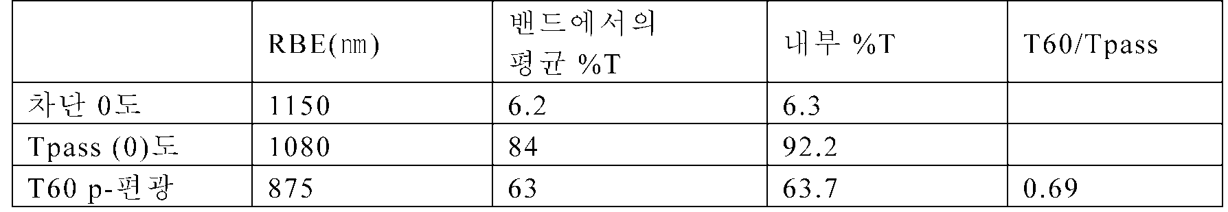
이들 값은 광학 필름 4.1의 내부 투과율 값의 계산된 값과 거의 일치한다. 도 23에 플로팅되어 있는 데이터는 5%의 내부 Tblock과, 0도 및 60도 p-편광 광에 대한 92% 및 63%의 내부 통과축 투과율을 각각 나타낸다.These values almost coincide with the calculated value of the internal transmittance value of the optical film 4.1. The data plotted in FIG. 23 shows an internal Tblock of 5% and an internal pass axis transmittance of 92% and 63% for 0-degree and 60-degree p-polarized light, respectively.
이러한 광학 필름 4.2를 하기에 추가로 설명되는 라미네이트 구조체 3.2에서 시험하였으며, 여기서 필름 4.2를 라미네이팅하여 단일형 광을 형성하였다.This optical film 4.2 was tested in a laminate structure 3.2 described further below, wherein film 4.2 was laminated to form a single light.
광학 필름 4.3 : 1-축 시준 필름(s-편광), 275개의 미세층(Optical film 4.3: 1-axis collimation film (s-polarized), 275 microlayers 모델링됨Modeled ))
n×1 = 1.82, ny1 = 1.623, n1z = 1.505 및 n2 = 1.505의 굴절률(인용된 모든 굴절률 값은 633 ㎚의 파장에 적용됨)을 갖는 2개의 중합체 재료를 사용하는 다층 스택을 높은 각도에서 s-편광된 통과축 광을 실질적으로 반사하도록 설계하였다. 이는 큰 Δny = 1.623 내지 1.505를 사용함으로써 성취된다. 4개의 주요 편광 상태, 즉 차단축과 통과축 둘 모두에 대한 s-편광 및 p-편광에 대한 반사율을, 275개의 교번하는 층들의 다층 필름에 대해 모델링하였다. 수직 입사에서 400 ㎚ 내지 950 ㎚에 걸치는 차단축 반사 밴드를 갖는 굴절률 1.2의 매체에서 0 내지 90도의 모든 각도에 대해 내부 반사율이 도 25에 플로팅되어 있다. 도면에서, 곡선(2510)은 RSblock(θ) 및 RPblock(θ)을 나타내고, 곡선(2512)은 RSpass(θ)를 나타내며, 곡선(2514)은 RPpass(θ)를 나타낸다. 선(2516)은 90도의 공기에서의 입사각에 대응하는 ULI 굴절률 1.2 매체에서의 입사각을 나타낸다. 통과축 투과율은 수직 입사에서 약 35%이다. s-편광된 통과축 광에 대한 반사율은 각도에 따라 급격히 증가하는 반면, 통과축 p-편광된 광에 대한 반사율은 각도에 따라 대략 일정하다.layer stack using two polymer materials having refractive indices of nx1 = 1.82, ny1 = 1.623, n1z = 1.505 and n2 = 1.505 (all quoted refractive index values applied to a wavelength of 633 nm) And designed to substantially reflect the polarized passing axis light. This is accomplished by using a large? Yny = 1.623 to 1.505. The reflectance for s-polarized and p-polarized light for four major polarization states, i.e., the minor axis and the pass axis, was modeled for multilayer films of 275 alternating layers. The internal reflectance is plotted in Fig. 25 for all angles from 0 to 90 degrees in a medium with a refractive index of 1.2 with a single uniaxial reflection band extending from 400 nm to 950 nm in normal incidence. In the drawing, the
광학 필름 4.4 : 1-축 시준 필름(s-편광), 275개의 Optical film 4.4: 1-axis collimation film (s-polarized), 275 미세층Fine layer (제조됨)(Manufactured)
광학 필름 4.4는 전술된 광학 필름 3.4에 대한 다른 명칭이다.Optical Film 4.4 is another name for optical film 3.4 described above.
광학 필름 4.4를 대부분이 ULI 층을 포함하는, 라미네이트 형태의 다양한 추가 디스플레이 장치 내에 배치하고 시험하였다. 이들 추가 구조체는 이제 설명될 구조체 2.1 내지 구조체 2.5로 지칭된다.The optical film 4.4 was placed and tested in a variety of additional display devices in the form of a laminate, most of which included a ULI layer. These additional structures are now referred to as structures 2.1 to 2.5 to be described.
구조체 2.1 : 패널로부터 Structure 2.1: From the Panel 이격된Spaced , 플레이트 상의 필름(, The film on the plate ( 공기갭Air gap ))
이러한 구조체에서, 반사 편광 필름을 광학 접착제로 아크릴 플레이트에 라미네이팅하고 이 조합체를 LC 디스플레이 패널과 백라이트 사이에 배치하였으며, 이때 조합체와, LC 패널과, 백라이트 사이에 공기 갭이 존재한다. LC 디스플레이 패널은 대각선 방향 크기가 101.6 ㎝(40 인치)인 삼성의 시판용 TV 세트(모델 LE-40M91B)로부터 획득하였으며, 전방 흡수 편광기 및 후방 흡수 편광기를 포함하였다. 라미네이트 구조체를 물론, 반사 편광 필름의 통과축이 디스플레이 패널의 후방 흡수 편광기의 통과축과 정렬되도록 배향시켰다. 백라이트는 대각선 방향 치수가 76.2 ㎝(30 인치)였다. 따라서, 101.6 ㎝(40 인치) TV 패널의 일부분만을 (구조체를 통해) 백라이트에 의해 조명하였다.In this structure, the reflective polarizing film is laminated to the acrylic plate with an optical adhesive and the combination is placed between the LC display panel and the backlight, where there is an air gap between the combination, the LC panel and the backlight. The LC display panel was obtained from Samsung's commercially available TV set (model LE-40M91B) with a diagonal size of 101.6 cm (40 inches) and included a front absorbing polarizer and a back absorbing polarizer. The laminated structure as well as the transverse axis of the reflective polarizing film were oriented so as to be aligned with the passing axis of the rear absorbing polarizer of the display panel. The backlight had a diagonal dimension of 76.2 cm (30 inches). Thus, only a portion of a 101.6 cm (40 inch) TV panel was illuminated (via the structure) by the backlight.
구조체 2.2 : Structure 2.2: ULIULI 를 갖지 않고서 디스플레이 패널에 In the display panel 라미네이팅된Laminated 필름 film
이러한 구조체는, 반사 편광 필름을 아크릴 플레이트가 아닌 LC 디스플레이 패널에 라미네이팅한 것을 제외하고, 구조체 2.1과 유사하였다. 비드형 이득 확산기 층을 광학 필름의 다른 주 표면에 적용하여, 도 15에 도시된 것과 유사한 구조체를 형성하였다.This structure was similar to structure 2.1, except that the reflective polarizing film was laminated to an LC display panel rather than an acrylic plate. A bead shaped diffuser layer was applied to the other major surface of the optical film to form a structure similar to that shown in Fig.
구조체 2.3 : Structure 2.3: ULIULI 를 갖고서 디스플레이 패널에 To the display panel 라미네이팅된Laminated 필름 film
이러한 구조체는, 광학적으로 두꺼운 ULI 층을 반사 편광 필름과 광학 접착제 사이에 적용하여서 도 16에 도시된 것과 유사한 구조체를 형성한 것을 제외하고, 구조체 2.2와 유사하였다.This structure was similar to structure 2.2, except that an optically thick ULI layer was applied between the reflective polarizing film and the optical adhesive to form a structure similar to that shown in FIG.
구조체 2.4 : Structure 2.4: ULIULI 및 프리즘 필름을 갖고서 디스플레이 패널에 And a prism film on the display panel 라미네이팅된Laminated 필름 film
이러한 구조체는, 프리즘이 ULI의 제2 층으로 평면화된 프리즘 BEF 필름을 라미네이션에 포함시켜서 도 17에 도시된 것과 유사한 구조체를 형성한 것을 제외하고, 구조체 2.3과 유사하였다. BEF 필름은 PET 기재 층을 포함하였으며, PET 기재 층의 복굴절은 아마 라미네이트 구조체 내에서 광의 편광 상태를 부분적으로 변화시키는 효과를 가져서, 약간 감소된 휘도 측정값에 기여한다.This structure was similar to structure 2.3, except that the prism included a prism BEF film planarized into a second layer of ULI into the lamination to form a structure similar to that shown in FIG. The BEF film comprises a PET substrate layer and the birefringence of the PET substrate layer has the effect of partially changing the polarization state of light in the flax laminate structure, contributing to a slightly reduced luminance measurement.
구조체 2.5 : Structure 2.5: ULIULI 및 체적 And volume 확산기를Spreader 갖고서 디스플레이 패널에 To the display panel 라미네이팅된Laminated 필름 film
이러한 구조체는, 비드형 확산 층을 체적 확산기 층으로 대체하여서 도 18에 도시된 것과 유사한 구조체를 형성한 것을 제외하고, 구조체 2.3과 유사하였다. 체적 확산기의 전달 계수(전달 계수 = (F-B)/(F+B), 여기서 F는 전방 반구체에서 요소에 의해 산란되는 입사 램버시안 광의 양을 나타내고, B는 후방 반구체에서 요소에 의해 산란되는 입사 램버시안 광의 양을 나타냄)는 80%였다.This structure was similar to structure 2.3, except that the beaded diffusion layer was replaced with a bulk diffuser layer to form a structure similar to that shown in Fig. The transfer coefficient of the volume diffuser (transfer coefficient = (FB) / (F + B), where F represents the amount of incident Lambertian cyan light that is scattered by the element in the forward hemisphere and B is scattered by the element in the rear hemisphere Indicating the amount of incident Lambertian cyan light) was 80%.
각각의 구조체 2.1 내지 구조체 2.5를 광학 필름 4.4(3.4)를 사용해 축방향 휘도, 최대 휘도, 콘트라스트, 및 시야각에 대해 측정하였다. 시야각은 "수평" 관찰 평면 및 "수직" 관찰 평면에서 개별적으로 측정하였다. 디스플레이 패널이 텔레비전 시청을 위해 사용되는 표준 배향으로, 즉 보통의 방의 벽에 평행하게 배치된 상태에서, "수평" 관찰 평면은 방의 바닥에 평행하게(그리고 디스플레이 패널의 평면에 수직으로) 배향되고, "수직" 관찰 평면은 수직방향으로 그러나 디스플레이 패널의 평면과 수평 관찰 평면 둘 모두에 수직으로 배향된다. 따라서, 수평 관찰 평면과 수직 관찰 평면의 교선은 디스플레이 패널에 수직인 축방향을 형성한다. 주어진 평면에서 측정한 시야각은 휘도가 최대 휘도의 50%까지 감소되는, 평면내 방향들 사이의 전각(full angle)이었다.Each of Structures 2.1 to 2.5 was measured with respect to axial luminance, maximum luminance, contrast, and viewing angle using optical film 4.4 (3.4). The viewing angles were measured separately in the "horizontal" viewing plane and the "vertical" viewing plane. The horizontal viewing plane is oriented parallel to the floor of the room (and perpendicular to the plane of the display panel), with the display panel in a standard orientation used for television viewing, i.e. parallel to the wall of a normal room, The "vertical" observation plane is oriented vertically but perpendicular to both the plane of the display panel and the horizontal viewing plane. Thus, the intersection of the horizontal observation plane and the vertical observation plane forms an axial direction perpendicular to the display panel. The viewing angle measured in a given plane was the full angle between in-plane directions, where the luminance was reduced by 50% of the maximum luminance.
측정 결과는 다음과 같다:The measurement results are as follows:

추가의 작업에서, 광학 필름 4.2를 중실형 도광체를 포함하는 디스플레이-관련 구조체 내에 배치하였다. 이러한 추가 구조체는 구조체 3.2로 지칭되며, 이는 기준 구조체 3.1과 함께 이제 설명될 것이다.In a further operation, the optical film 4.2 was placed in a display-related structure comprising a solid-state light guide. This additional structure is referred to as structure 3.2, which will now be described with reference structure 3.1.
구조체 3.1 : Structure 3.1: 중실형Solid type 도광체를The light guide 사용하는 using 에지형Edge type 백라이트, 기준 (공기 갭) Backlight, reference (air gap)
구조체 3.1 및 구조체 3.2의 실시 형태를 위한 제조에 사용된 하기의 재료가 상당히 상세하게 설명된다: 반사 편광 필름 상에의 핸드-코팅된(hand-coated) 프리즘의 제조(베르데(Verde) 중합성 수지 조성물, 및 MOF 상에의 프리즘의 제조를 포함함); 접착제(PSA); 3-층 코팅(체적 확산기 코팅 용액의 제조, 초저 헤이즈 저 굴절률 코팅 용액의 제조, 저 헤이즈 저 굴절률 코팅 용액의 제조, 코팅 절차, 및 PET 상에의 3-층 코팅의 제조를 포함함); 도광체 플레이트; 백색 후방 반사기; 및 백라이트.The following materials used in fabrication for embodiments of structures 3.1 and 3.2 are described in considerable detail: Fabrication of a hand-coated prism on a reflective polarizing film (Verde polymeric resin Compositions, and prisms on MOF); Adhesive (PSA); 3-layer coating (including preparation of a volume diffuser coating solution, preparation of ultra low haze low refractive index coating solution, preparation of low haze low refractive index coating solution, coating procedure, and preparation of 3-layer coating on PET); A light guide plate; White rear reflector; And backlight.
반사 편광 필름 상에의 핸드-코팅된 프리즘의 제조.Preparation of hand-coated prisms on reflective polarizing films.
"베르데 수지 조성물은 다음과 같았다: CN120(미국 펜실베이니아주 엑스톤 소재의 사토머(Sartomer)로부터 입수가능함)으로 판매되는 에폭시 아크릴레이트 75% (w/w), SR-339(미국 펜실베이니아주 엑스톤 소재의 사토머로부터 입수가능함)로 판매되는 2-페녹시에틸 아크릴레이트 25% (w/w), 및 다로큐르(Darocur)(등록상표) TPO로 판매되는 2,4,6트라이메틸벤조일-다이페닐-포스핀옥사이드 0.1% (pph) 및 다로큐르(등록상표) 1173으로 판매되는 2-하이드록시-2-메틸-l-페닐-프로판-1-온 0.25% (pph)(둘 모두는 스위스 소재의 시바 스페셜티 케미칼즈 인크.(Ciba Specialty Chemicals Inc.)로부터 입수가능함).The Verde resin composition was as follows: 75% (w / w) epoxy acrylate sold as CN120 (available from Sartomer, Exton, Pa.), SR-339 (Exton, 25% (w / w) of 2-phenoxyethyl acrylate sold as Sartomer, and 2,4,6-trimethylbenzoyl-dicarboxylic acid sold under the trade name Darocur TM TPO Phenyl-propan-1-one 0.25% (pph) (both available from Switzerland) sold as 0.1% (pph) phenyl-phosphine oxide and DaRocure (R) 1173 Available from Ciba Specialty Chemicals Inc.).
다층 광학 필름 상에의 프리즘의 제조. 베르데 수지 조성물을 사용해 휘도 향상 필름을 제조하였다. 비퀴티™ BEF II 90/50(미국 미네소타주 세인트 폴 소재의 쓰리엠 컴퍼니로부터 구매가능함) 상에서 발견된 프리즘 기하학적 형상 패턴과 유사한, 50 마이크로미터의 공칭 피치 간격을 갖는 90도 프리즘들의 선형 열(row)들로 이루어진 20.3 ㎝(8") × 27.9 ㎝(11") 금속 마스터를 고온 플레이트 상에 배치하고 66℃(150℉)까지 가열하였다. 약 3 그램의 따뜻한 수지를 MOF에 적용하고 미세복제 공구에 대항하여 배치하였으며, 선형 프리즘들이 MOF의 기계 방향에 대략 평행하게 되도록 배향시켰다. MOF, 중합성 베르데 수지, 및 공구를 대략 66℃(150℉)에 설정된 가열된 라미네이터를 통과시켜 균일하게 두꺼운 샘플을 생성하였다. 필름 및 코팅된 중합성 수지 샘플을 포함하는 공구를, 15.2 미터/분(50 fpm)으로, 100% 출력으로 설정된 2개의 236 W/㎝(600 W/인치) D-전구를 포함하는 미국 메릴랜드주 게이더스버그 소재의 퓨전 유브이 시스템즈, 인크.(Fusion UV Systems, Inc.)의 프로세서를 통과시켰다.Preparation of prisms on multilayer optical films. A brightness enhancement film was prepared using a Berde resin composition. Linear rows of 90 degree prisms with a nominal pitch spacing of 50 micrometers, similar to the prismatic geometric patterns found on Viquiti
접착제(PSA). 0.1% 비스아미드 가교결합제를 일본 도쿄 소재의 소켄 케미칼즈(Soken Chemicals)로부터 입수가능한 SK Dyne 2003K 습식 접착제에 부가하였으며, 이 혼합물을 종래의 슬롯 다이(slot die)를 사용해 0.051 ㎜(2 밀(mil)) 폴리에스테르 실리콘 이형 라이너(미국 미주리주 세인트 루이스 소재의 시피 필름즈(CP Films)로부터 입수가능한 T50) 상에 코팅하고 용매를 건조시켜서, 0.025 ㎜(1 밀) 두께의 접착제 코팅을 생성하였다. 제2 이형 라이너를 건조된 접착제의 표면에 라미네이팅하였다: 차별 이형(differential release)을 갖는 0.051 ㎜(2 밀) 폴리에스테르 실리콘 이형 라이너(시피 필름즈로부터 또한 입수가능한 T10).Adhesive (PSA). A 0.1% bisamide crosslinking agent was added to the SK Dyne 2003K wet adhesive available from Soken Chemicals, Tokyo, Japan, and the mixture was applied using a conventional slot die to a depth of 0.051 mm (2 mil )) Polyester silicone release liner (T50 available from CP Films, St. Louis, Mo.) and the solvent was dried to produce a 0.025 mm (1 mil) thick adhesive coating. The second release liner was laminated to the surface of the dried adhesive: a 0.051 mm (2 mil) polyester silicone release liner with differential release (T10 also available from Sheffield).
3-층 코팅.Three-layer coating.
체적 확산기 코팅 용액의 제조. 체적 확산기 코팅 용액 (A)를 제조하였다. 먼저, 144.8 g의 메탄올, 49.5 g의 포토머(photomer) 6010 (미국 뉴저지주 우드랜드 파크 소재의 사이텍 인더스트리즈(Cytec Industries)), 22.0 g의 SR833S, 및 25.3 g의 SR9003(미국 펜실베이니아주 엑스톤 소재의 사토머)을 균질 용액이 될 때까지 초음파 하에서 함께 혼합하였다. 그 후에, 96.8 g의 SX-350H(3.5 마이크로미터 폴리스티렌 비드, 일본 도쿄 소재의 소켄 케미칼 앤 엔지니어링 컴퍼니 엘티디(Soken Chemical & Engineering Co., Ltd)로부터 입수가능함)를 신속 교반 하에서 부가하였다. 이 유백색 용액을 하룻밤 동안 교반하였고, 이어서 144.8 g의 1-메톡시-2-프로판올 및 2.48 g의 다로큐르(등록상표) 4265(미국 노스캐롤라이나주 하이 포인트 소재의 시바 스페셜티 케미칼즈)를 신속 교반 하에서 상기의 용액에 부가하여 균질의 체적 확산기 용액을 형성하였다.Preparation of Volumetric Diffuser Coating Solution. A volume diffuser coating solution (A) was prepared. First, 144.8 grams of methanol, 49.5 grams of photomer 6010 (Cytec Industries, Woodland Park, NJ), 22.0 grams of SR833S, and 25.3 grams of SR9003 (Exton, Pennsylvania, USA) Were mixed together under ultrasound until a homogeneous solution was obtained. Thereafter, 96.8 g of SX-350H (3.5 micrometer polystyrene beads, available from Soken Chemical & Engineering Co., Ltd., Tokyo, Japan) was added under rapid agitation. The milky white solution was stirred overnight and then 144.8 g of 1-methoxy-2-propanol and 2.48 g of Darocur® 4265 (Ciba Specialty Chemicals, High Point, NC) Was added to the solution to form a homogeneous volume diffuser solution.
초저 헤이즈 저 굴절률 코팅 용액의 제조. 코팅 용액 "B"를 제조하였다. 응축기 및 온도계를 갖춘 2 리터의 3구 플라스크 내에서, 960 그램의 IPA-ST-up 유기실리카 긴 입자, 19.2 그램의 탈이온수, 및 350 그램의 1-메톡시-2-프로판올을 신속 교반 하에서 혼합하였다. 긴 입자는 직경이 약 9 ㎚ 내지 약 15 ㎚의 범위였고 길이가 약 40 ㎚ 내지 약 100 ㎚의 범위였다. 입자들을 15.2 중량% IPA 중에 분산시키고, 22.8 그램의 실퀘스트(Silquest) A174 실란을 플라스크에 부가하였다. 생성된 혼합물을 30분 동안 교반하였다. 혼합물을 16시간 동안 81℃에 유지하였다. 다음에, 이 용액을 실온까지 냉각되게 하였고, 40℃ 수조 하에서 회전식 증발기를 사용해 용액 중의 약 950 그램의 용매를 제거하여서, 41.7 중량% A-174-변성된 긴 실리카가 1-메톡시-2-프로판올 중에 분산된 투명한 A174-변성된 긴 실리카 용액을 생성하였다. 다음에, 200 그램의 투명한 A-174-변성된 긴 실리카 용액, 83.4 그램의 SR 444, 1.6 g의 테고 래드(TEGO Rad) 2250, 0.4 g의 이르가큐어(Irgacure) 819, 1.25 그램의 이르가큐어 184, 및 233 그램의 아이소프로필 알코올을 함께 혼합하고 교반하여서, 32.5 중량% 고형물을 갖는 균질 코팅 용액 C를 생성하였다.Preparation of ultra low haze low refractive index coating solution. Coating solution "B ". In a two liter three-necked flask equipped with a condenser and thermometer, 960 grams of IPA-ST-up organosilica long particles, 19.2 grams of deionized water, and 350 grams of 1-methoxy-2-propanol were mixed Respectively. The long particles had a diameter ranging from about 9 nm to about 15 nm and a length ranging from about 40 nm to about 100 nm. The particles were dispersed in 15.2 wt% IPA and 22.8 grams of Silquest A174 silane was added to the flask. The resulting mixture was stirred for 30 minutes. The mixture was maintained at 81 DEG C for 16 hours. The solution was then allowed to cool to room temperature and about 950 grams of the solvent in the solution was removed using a rotary evaporator under a 40 ° C water bath to give 41.7 wt% A-174-denatured long silica as 1-methoxy-2- Yielding a transparent A174-modified long silica solution dispersed in propanol. Next, 200 grams of a transparent A-174-modified long silica solution, 83.4 grams of SR 444, 1.6 grams of TEGO Rad 2250, 0.4 grams of Irgacure 819, Cure 184, and 233 grams of isopropyl alcohol were mixed together and stirred to produce a homogeneous coating solution C having 32.5 weight percent solids.
저 헤이즈 저 굴절률 코팅 용액의 제조. 코팅 용액 "C"를 제조하였다. 먼저, 360 g의 날코(Nalco) 2327 콜로이드 실리카 입자(40 중량% 고형물 및 약 20 나노미터의 평균 입자 직경) 및 300 g의 1-메톡시-2-프로판올을, 응축기 및 온도계를 갖춘 2 리터의 3구 플라스크 내에서 신속 교반 하에 함께 혼합하였다. 다음에, 22.15 g의 실퀘스트 A-174 실란을 부가하고, 이 혼합물을 10분 동안 교반하였다. 이어서 추가 400 g의 1-메톡시-2-프로판올을 부가하고, 이 혼합물을 가열 맨틀(heating mantle)을 사용해 85℃에서 6시간 동안 가열하였다. 생성된 용액을 실온까지 냉각되게 하였고, 60℃ 수조 하에서 회전식 증발기를 사용해 대부분의 물 및 1-메톡시-2프로판올 용매(약 700 g)를 제거하였다. 생성된 용액은 44 중량% A-174 변성된 20 ㎚ 실리카가 1-메톡시-2-프로판올 중에 분산된 투명한 A-174 변성된 실리카 용액이었다. 다음에, 120 g의 A-174 변성된 실리카 용액, 17.6 g의 CN2302, 35.2 g의 SR444, 1.05 g의 테고 래드 2250, 0.264 g의 이르가큐어 819, 0.81 g의 이르가큐어 184, 및 156 g의 아이소프로필 알코올을 교반에 의해 함께 혼합하여 균질 코팅 용액 C를 형성하였다.Preparation of low haze low refractive index coating solution. To prepare a coating solution "C ". First, 360 g of Nalco 2327 colloidal silica particles (40 wt.% Solids and an average particle diameter of about 20 nanometers) and 300 g of 1-methoxy-2-propanol were placed in a two liter flask equipped with a condenser and thermometer Were mixed together under rapid stirring in a three-necked flask. Next, 22.15 g of Silquest A-174 silane was added and the mixture was stirred for 10 minutes. An additional 400 g of 1-methoxy-2-propanol was then added and the mixture was heated at 85 [deg.] C for 6 hours using a heating mantle. The resulting solution was allowed to cool to room temperature and most of the water and 1-methoxy-2 propanol solvent (about 700 g) was removed using a rotary evaporator under a 60 ° C water bath. The resulting solution was a clear A-174 modified silica solution in which 44 wt% A-174 modified 20 nm silica was dispersed in 1-methoxy-2-propanol. Next, 120 g of A-174 modified silica solution, 17.6 g of CN2302, 35.2 g of SR444, 1.05 g of Tegolard 2250, 0.264 g of Irgacure 819, 0.81 g of Irgacure 184, and 156 g Of isopropyl alcohol were mixed together by stirring to form a homogeneous coating solution C.
코팅 절차. 코팅 절차 D를 개발하였다. 먼저, 코팅 용액을 20.4 ㎝(8 인치) 폭의 슬롯-유형 코팅 다이 내로 10 ㏄/분의 속도로 시린지-펌핑하였다. 슬롯 코팅 다이는 152 ㎝/분(10 피트/분)으로 이동하는 기재 상에 20.4 ㎝ 폭의 코팅을 균일하게 분배하였다. 다음에, 코팅된 기재를, UV 방사선의 통과를 허용하는 석영 윈도우(window)를 포함하는 UV LED 경화 챔버를 통과시킴으로써 코팅을 중합시켰다. UV-LED 뱅크(bank)는 160개의 UV-LED들의 직사각형 어레이, 8 다운-웨브(down-web) × 20 크로스-웨브(cross-web)(대략 10.2 ㎝ × 20.4 ㎝ 영역을 덮음)를 포함하였다. LED(미국 노스캐롤라이나주 더럼 소재의 크리, 인크.(Cree, Inc.)로부터 입수가능함)는 385 ㎚의 공칭 파장에서 작동하였고, 전형적으로는 45 볼트에서 8 암페어에서 작동되어서, 제곱센티미터당 0.212 줄(joule)의 UV-A 선량(dose)을 생성하였다. 텐마(TENMA) 72-6910 (42VIlOA) 전원 장치(미국 오하이오주 스프링보로 소재의 텐마(Tenma)로부터 입수가능함)에 의해 팬 냉각 UV-LED 어레이에 전력을 공급하였다. UV-LED를 기재로부터 대략 2.5 ㎝의 거리에 경화 챔버의 석영 윈도우 위에 위치시켰다. UV-LED 경화 챔버에 46.7 리터/분(시간당 100 세제곱피트)의 유량으로 질소의 유동을 공급하여, 경화 챔버 내에 대략 150 ppm의 산소 농도를 생성하였다. UV LED 챔버 내의 총 산소 수준을 조절하기 위해 추가 산소 유동을 공급하였다. UV-LED에 의해 중합된 후에, 코팅된 기재를 304.8 ㎝/분(10 피트/분)의 웨브 속도로 1분 동안 66℃(150 ℉)의 상태에 있는 건조 오븐으로 이송함으로써 경화된 코팅 중의 용매를 제거하였다. 다음에, H-전구로 구성된 퓨전 시스템(Fusion System) 모델 I300P(미국 메릴랜드주 게이더스버그 소재의 퓨전 유브이 시스템즈로부터 입수가능함)를 사용해 건조된 코팅을 후-경화시켰다. UV 퓨전 챔버에 질소의 유동을 공급하여, 챔버 내에 대략 50 ppm의 산소 농도를 생성하였다.Coating procedure. Coating procedure D was developed. First, the coating solution was syringe-pumped at a rate of 10 cc / min into a 20.4 cm (8 inch) wide slot-type coating die. The slot coating die uniformly dispensed a 20.4 cm wide coating on a substrate moving at 152 cm / min (10 ft / min). The coated substrate was then polymerized by passing it through a UV LED curing chamber containing a quartz window that allowed the passage of UV radiation. The UV-LED bank included a rectangular array of 160 UV-LEDs, 8 down-
PET 상에의 3-층 코팅의 제조. 먼저 코팅 용액 A를 코팅 절차 D에 따라 점착 프라이밍된(primed) 0.051 ㎜(2 밀) PET 필름(듀폰 테이진 필름즈(DuPont Teijin Films)로부터 입수가능함) 상에 코팅하였으며, 이때 UV-LED는 꺼진 상태이고, 유량은 30 ㏄/분이었다. 코팅된 기재를 66℃(150 ℉)의 상태에 있는 건조 오븐으로 이송함으로써 경화된 코팅 중의 용매를 제거하였다. 다음에, 질소 및 100% UV 출력 하에서 작동되는, H-전구로 구성된 퓨전 시스템 모델 I300P(미국 메릴랜드주 게이더스버그 소재의 퓨전 유브이 시스템즈로부터 입수가능함)를 사용해 건조된 코팅을 후-경화시켰다. 이는 PET 필름 상에 체적 확산기 코팅을 생성한다. 코팅 공정 D를 사용해 코팅 용액 C를 체적 확산기 코팅의 반대측에 코팅하였으며, 이때 UV-LED는 9 암페어에서 작동하였고, 유량은 12 ㏄/분이었으며, 산소 수준은 2000 ppm으로 조절하였다. UV-LED에 의해 중합된 후에, 질소 및 100% UV 출력 하에서 작동되는, H-전구로 구성된 퓨전 시스템 모델 I300P(미국 메릴랜드주 게이더스버그 소재의 퓨전 유브이 시스템즈로부터 입수가능함)를 사용해 경화된 코팅 중의 용매를 제거하고 최종 경화시켰다. 이는 상부 표면에서 1.4, 그리고 PET와의 계면에서 1.21의 유효 굴절률을 갖는 구배 저 굴절률 코팅을 생성한다. 코팅 용액 B를 D의 동일한 공정을 사용해 체적 확산기 코팅의 상면에 코팅하였으며, 이때 UV-LED는 9 암페어에서 작동하였고, 유량은 10 ㏄/분이었으며, 산소 수준은 1000 ppm으로 조절하였다. UV-LED에 의해 중합된 후에, 질소 및 100% UV 출력 하에서 작동되는, H-전구로 구성된 퓨전 시스템 모델 I300P(미국 메릴랜드주 게이더스버그 소재의 퓨전 유브이 시스템즈로부터 입수가능함)를 사용해 경화된 코팅 중의 용매를 제거하고 최종 경화시켰다. 이는 상부 표면에서 1.26, 그리고 체적 확산기와의 계면에서 1.20의 굴절률을 갖는 구배 저 굴절률 코팅을 생성한다.Preparation of a three-layer coating on PET. Coating Solution A was first coated on a 0.051 mm (2 mil) primed PET film (available from DuPont Teijin Films) according to coating procedure D, wherein the UV-LED was turned off , And the flow rate was 30 cc / min. The solvent in the cured coating was removed by transferring the coated substrate to a drying oven at a temperature of 66 DEG C (150 DEG F). Next, the dried coating was post-cured using a Fusion System Model I300P (available from Fusion Uveys Systems, Inc., Gaithersburg, MD) configured with an H-bulb, operated under nitrogen and 100% UV output. This creates a volumetric diffuser coating on the PET film. Coating solution D was used to coat coating solution C on the opposite side of the volume diffuser coating, where the UV-LED operated at 9 amps, the flow rate was 12 cc / min and the oxygen level was adjusted to 2000 ppm. After being polymerized by UV-LEDs, a fusion system Model I300P (available from Fusion Uveys Systems, Inc., Gaithersburg, Maryland) configured with an H-bulb, operated under nitrogen and 100% UV output, The solvent was removed and finally cured. This results in a gradient low refractive index coating with an effective refractive index of 1.4 at the top surface and 1.21 at the interface with PET. Coating solution B was coated on top of the bulk diffuser coating using the same process of D, where the UV-LED was operated at 9 amps, the flow rate was 10 cc / min and the oxygen level was adjusted to 1000 ppm. After being polymerized by UV-LEDs, a fusion system Model I300P (available from Fusion Uveys Systems, Inc., Gaithersburg, Maryland) configured with an H-bulb, operated under nitrogen and 100% UV output, The solvent was removed and finally cured. This produces a gradient low refractive index coating with a refractive index of 1.26 at the top surface and 1.20 at the interface with the volume diffuser.
도광체 플레이트(light guide plate, LGP). 코어트로닉 컴퍼니(중화민국 대만 300 신주 소재)의 모델 AUT1982T32로부터 LGP를 획득하였다. LGP는 폴리(메틸 메타크릴레이트)로 제조되며, 바닥 표면에 백색 인쇄 도트(dot)들이 있고, 두께가 6 ㎜, 폭이 385 ㎜, 그리고 길이가 306 ㎜이다.Light guide plate (LGP). We obtained LGP from the model AUT1982T32 of Coretronic Company (300 New Hsinju, Taiwan). LGP is made of poly (methyl methacrylate), with white printed dots on the bottom surface, 6 mm in thickness, 385 mm in width, and 306 mm in length.
백색 후방 반사기(white back reflector, WBR). 미국 캘리포니아주 월넛 소재의 뷰소닉 컴퍼니(Viewsonic Company)로부터 입수가능한 뷰소닉(Viewsonic) 55.9 ㎝(22 인치) 모니터(모델 # : VLED221wm)로부터 WBR을 획득하였다.White back reflector (WBR). A WBR was obtained from a Viewsonic 55.9 cm (22 inch) monitor (Model #: VLED221wm), available from Viewsonic Company, Walnut, Calif., USA.
백라이트. 55.9 ㎝(22") 뷰소닉 모니터 모델 # VLED221wm을 분해하여 백라이트를 패널로부터 분리하였다. 백라이트는 크기가 대략 473 ㎜ 폭 × 306 ㎜ 길이였다. 백라이트는 후방 벽과 정렬된 WBR 및 백라이트의 각각의 473 ㎜ 에지를 따른, 약 6 ㎜의 피치를 갖는, 78개의 LED의 열을 포함하였다. 각각의 에지 상의 63개의 LED만을 실시예에 대해 사용하였다. 구조체 3.2는 LGP에 라미네이팅된 다층 반사 편광기를 포함하며, 여기서 반사 편광기의 통과축은 385 ㎜ 길이와 정렬된다. 이어서 다층 반사 편광기의 통과축이 LED의 열에 평행하도록 편광된 LGP를 WBR의 상면에 있는 백라이트 내로 배치한다. 실시예에서 ULI와 프리즘 코팅된 MOF를 조합하기 위해 라미네이션을 사용하였다. 인타이틀먼트 구조체(entitlement construction)의 경우, 3-층 코팅이 라미네이션에 대한 필요성 없이 MOF 상에 직접 코팅될 수 있다. 모든 실시예에서, MOF는 그의 통과축이 중실형 LGP - 이곳에 광 엔진이 설치됨 - 의 긴 변에 평행하도록 배열하였다.Backlight. The backlight was approximately 473 mm wide x 306 mm long. The backlight was divided into 473 mm of WBR aligned with the rear wall and 473 mm of backlight, respectively, aligned with the rear wall, With a pitch of about 6 mm, along the edge of the LEDs. Only 63 LEDs on each edge were used for the example. [0100] Structure 3.2 includes a multilayer reflective polarizer laminated to LGP, The polarized LGP is then placed into the backlight on the top surface of the WBR so that the pass axis of the multilayer reflective polarizer is parallel to the row of LEDs. In the example, the ULI and prism coated MOF Lamination was used to combine. For entitlement construction, a three-layer coating can be applied to the MOF phase without the need for lamination. There may be directly coated on all embodiments, MOF is the axis passing through its solid LGP - were arranged parallel to the longer side of the-installed in this place the light engine to.
상기의 배경 정보를 갖고서, 공기 갭을 포함하는 기준 백라이트 구조체(구조체 3.1)를 도 26a의 개략 측면도에 도시된 바와 같이 제조하였다. 이 도면은 반사 편광 필름(2612), BEF 필름(2614), 이득 확산기(2616), 도광체 플레이트(2618)(그의 후방 표면 상에 추출 도트(2620)를 가짐), 및 백색 후방 반사기(2622)를 갖는 백라이트(2610)를 도시하고 있다. LED(2624a, 2624b)들은 도광체의 에지형 조명을 제공하였다. 개략 측면도가 도 1(a)에 도시되어 있는 백라이트를 제조하였다. 백라이트는 전술된 WBR(요소(2622)에 대한 것), LGP(요소(2618)에 대한 것), LED 램프(요소(2624a, 2624b)들), 이득 확산기(요소(2616)에 대한 것), BEF3-7T 프리즘 필름(요소(2614)에 대한 것), 및 반사 편광기(2612)에 대한 DBEF-D400을 포함하였다. 63개의 LED를 LGP의 각각의 에지 부근에 배치하고 LGP의 폭(385 ㎜)을 따라 규칙적으로 배열하였다.With the above background information, a reference backlight structure (structure 3.1) comprising an air gap was produced as shown in the schematic side view of Figure 26a. This figure shows a reflective
시야각의 함수로서의 백라이트 중심의 휘도, 축방향 휘도(니트의 단위), 휘도 반치각을 아우트로닉 코노스코프 코노스테이지 3(독일 칼스루에 소재의 아우트로닉-멜처스 게엠베하로부터 입수가능함)를 사용해 측정하였다. 측정을 행하기 전에, 도 26a에 도시되지 않은 선형 흡수 편광기를 그의 통과축이 LGP의 긴 변에 평행한 상태로 DBEF-D400의 상면에 배치하였다. 공기에서 극각의 함수로서의 휘도를 수평 평면(곡선(2632) 참조) 및 수직 평면(곡선(2630) 참조)에서 측정하였으며, 이는 도 26b에 플로팅되어 있다.The luminance of the backlight center as a function of the viewing angle, the axial luminance (in units of knit), and the luminance half-value angle are measured using the Auroconic Konoscon Kono Stage 3 (available from Autronic - Melissa GmbH, Karlsruhe, Germany) Respectively. Before the measurement, a linear absorption polarizer not shown in Fig. 26A was disposed on the upper surface of the DBEF-D400 in a state in which its passing axis was parallel to the long side of the LGP. The luminance as a polar angle function in air was measured in a horizontal plane (see curve 2632) and a vertical plane (see curve 2630), which is plotted in FIG. 26B.
구조체 3.2 : Structure 3.2: ULIULI 와 함께 with 중실형Solid type 도광체Light guide /필름/프리즘 라미네이트를 갖는 백라이트/ Backlit Film / Prism Laminate
공기 갭을 포함하지 않고, 1-축 시준 침지형 반사 편광 필름(광학 필름 4.2), 및 광학적으로 두꺼운 ULI 층을 포함하는 라미네이팅된 백라이트를 도 27a의 개략 측면도에 도시된 바와 같이 제조하였다. 도면은 다층 반사 편광기(2714)(광학 필름 4.2) 상에 형성된 BEF 프리즘(2712), 감압 접착제(pressure sensitive adhesive, PSA) 층(2716, 2726)들, 광학적으로 두꺼운 ULI 층(2718), 체적 확산기(2720), 3-층 코팅을 갖는 PET 층(2722), z-구배를 갖는 ULI 층(2724), 상부에 추출 도트(2730)를 갖는 도광체 플레이트(2728), 백색 후방 반사기(2732), 및 에지형 광원(2734a, 2734b)들을 갖는 라미네이트 백라이트 구조체(2710)를 도시하고 있다. 이들 구성요소의 상세 사항은 위에 제공되어 있다. 광원(2734a, 2734b)들의 경우, 63개의 LED를 LGP의 각각의 에지 부근에 배치하고 LGP의 폭(385 ㎜)을 따라 규칙적으로 배열하였다.A laminated backlight comprising a 1-axis collimated reflective polarizing film (optical film 4.2) and an optically thick ULI layer without an air gap was prepared as shown in the schematic side view of FIG. 27A. The figure shows a
구조체 3.2와 관련하여 설명된 것과 유사한 측정을 행하였다. 도 27b는 수평 평면(곡선(2742) 참조) 및 수직 평면(곡선(2740) 참조)에서 측정한, 공기에서의 극각의 함수로서 휘도를 도시하고 있다.Measurements similar to those described in relation to structure 3.2 were performed. Figure 27B shows the luminance as a function of the polar angle in air measured in the horizontal plane (see curve 2742) and the vertical plane (see curve 2740).
광학 필름 4.2를 사용하는 구조체 3.2는 백라이트 응용에 요구되는 몇몇 중요한 기능, 즉 (1) 광 출력 시준, (2) 편광된 출력을 증명하였다. ULI, 특히 도광체에 가까운 z-구배 ULI 층의 고유의 헤이즈로 인해, 디스플레이 균일성이 약간 변화하였다. 현재의 시스템보다 더 많은 광이 에지 가까이에서 추출되며, 이는 추출기 설계를 재-최적화함으로써 용이하게 보상될 수 있다. 이러한 이유로, 실시 형태들 사이의 공정한 비교를 행하기 위해 디스플레이 상부, 중심, 및 바닥을 포함한 디스플레이 상의 3개의 지점을 측정하였다. 결과가 하기의 표에 요약되어 있다. 실시예 2인 단일형의 편광된 중실형 도광체의 평균 휘도는 현재의 시스템의 86.5%이다. 성능은 (1) 핸드 코팅 대신에 정밀 프리즘 코팅, (2) PSA 및 PET의 층을 포함한 비-부가 가치(non-value added) 구성요소의 제거, (3) ULI에서의 헤이즈 감소, (4) 프리즘 코팅을 위한 더 높은 굴절률 수지, (5) 추가의 MOF 최적화에 의해 추가로 개선될 수 있다.Structure 3.2 using optical film 4.2 demonstrated several important functions required for backlight applications: (1) optical output collimation and (2) polarized output. Due to the inherent haze of the ULI, especially the z-gradient ULI layer close to the light guide, the display uniformity has changed slightly. More light is extracted near the edge than the current system, which can be easily compensated for by re-optimizing the extractor design. For this reason, three points on the display including the top, center, and bottom of the display were measured to make a fair comparison between the embodiments. The results are summarized in the following table. The average brightness of the single polarized solid state light guide of Example 2 is 86.5% of the current system. (1) elimination of non-value added components including layers of PSA and PET, (3) haze reduction in ULI, (4) Higher refractive index resin for prism coating, and (5) additional MOF optimization.
[표 : 구조체 3.1(DBEF를 사용함)과 구조체 3.2(광학 필름 4.2를 사용함)의 비교][Table: Comparison of structure 3.1 (using DBEF) and structure 3.2 (using optical film 4.2)]

추가 분석 및 논의Further analysis and discussion
전술된 바와 같이, 반사 편광기 성능의 몇몇 파라미터들은 LCD 백라이트, 또는 높은 각도에서의 세기(intensity)의 감소 및/또는 향상된 축상 세기를 요구하는 임의의 다른 편광된 조명 시스템에서의 유용성에 관하여 중요할 수 있다. 이들 파라미터는 위에서 논의된 %T block 및 %T00를 포함한다. 통과 상태의 s-편광 성분 및 p-편광 성분에 대한 투과율 값이 경사진 각도에서 서로 유사할 수 있는 2-축 시준 침지형 반사 편광기의 경우에, 파라미터는 또한 %TA60, %TA90, 및 %TU90을 포함할 수 있으며, 이들 각각은 s-편광 성분과 p-편광 성분의 평균값이다.As described above, some parameters of the reflective polarizer performance may be important for the LCD backlight, or for its usefulness in any other polarized illumination system requiring a reduction in intensity at high angles and / or improved axial intensity have. These parameters include% T block and% T00 discussed above. In the case of a two-axis collimated reflective polarizer where the transmittance values for the s-polarized component and the p-polarized component of the passing state can be similar to each other at an oblique angle, the parameters also include% TA60,% TA90, and% TU90 , Each of which is an average value of the s-polarized component and the p-polarized component.
이들 투과율 값은 이들이 적용될 수 있는 시스템의 요건으로 인해 소정 범위의 바람직한 값을 갖는다. 또한, 필름에 대한 이들 파라미터 중 하나를 변화시키는 것은 다른 파라미터들 중 하나 이상을 변화시킬 것이기 때문에 상반관계(trade-off)가 존재한다. 이에 대한 하나의 이유는 임의의 재료로부터 이용가능한 복굴절의 한계이다. PEN 및 PET와 같은 중합체는 반-결정질 중합체 필름에서 중합체 미결정들 및 분자 사슬들 중 일부의 배향으로 인해 복굴절을 나타낸다. 결정 및 분자 질서를 발생시키는 이러한 공정은 일반적으로 필름의 배향으로 지칭된다. 중합체 필름은 x 방향 또는 y 방향 중 어느 하나, 또는 둘 모두의 방향으로 배향될 수 있다. 임의의 방향으로의 필름의 배향은 그 방향에서뿐만 아니라, 다른 2개의 방향에서 반사율에 영향을 미칠 것이다. z 굴절률은 필름이 x 방향과 y 방향 둘 모두로 고도로 배향되는 경우 최소화될 것이다. x-굴절률은 최대값까지 증가될 수 있지만, 이는 y-굴절률을 최소값까지 감소시키는 희생이 있어야만 한다. 이들 특성은 공지되어 있지만, 전술된 5개의 파라미터를 최적화하는 것과 관련된 상반관계를 논의하기 위해 본 명세서에 재언급된다. 예를 들어, 고 굴절률 층의 y 굴절률을 증가시키기 위해 필름을 처리하는 것은 %T00를 감소시킬 것이지만, 이는 또한 x-굴절률을 감소시켜서, %T block을 증가시킬 것이다. 1차 근사에 대해, x 굴절률, y 굴절률, 및 z 굴절률의 합계는 일정하다. x 방향 또는 y 방향 중 어느 하나, 또는 둘 모두의 방향으로의 최대 배향에 의해, z 굴절률은 폴리에스테르 기반의 시스템에 대해, 그리고 마찬가지로 다른 이른바 "양의 복굴절 시스템"에 대해 최소화된다. y 방향으로의 배향의 증가를 수반하는 x-방향으로의 감소와 같은 배향의 비대칭은 z 굴절률을 대략 일정한 상태가 되게 할 수 있다.These transmittance values have a certain range of desirable values due to the requirements of the system to which they can be applied. In addition, there is a trade-off because changing one of these parameters for the film will change one or more of the other parameters. One reason for this is the limit of available birefringence from any material. Polymers such as PEN and PET exhibit birefringence due to orientation of polymer microcrystals and some of the molecular chains in the semi-crystalline polymer film. This process of generating crystals and molecular order is generally referred to as orientation of the film. The polymer film may be oriented in either the x direction or the y direction, or both directions. The orientation of the film in any direction will affect the reflectivity in the other two directions as well as in that direction. The z index of refraction will be minimized if the film is highly oriented both in the x and y directions. The x-index can be increased to a maximum value, but it must have a sacrifice that reduces the y-index to the minimum value. Although these characteristics are well known, they are recited herein to discuss the contradictions associated with optimizing the five parameters described above. For example, treating the film to increase the y index of refraction of the high refractive index layer will reduce% T00, but it will also decrease the x-index and increase the% T block. For the first order approximation, the sum of x refractive index, y refractive index, and z refractive index is constant. Due to the maximum orientation in either the x direction or the y direction, or both directions, the z index of refraction is minimized for polyester based systems and likewise for other so-called "positive birefringent systems ". The asymmetry of the orientation, such as the decrease in the x-direction with increasing orientation in the y-direction, can bring the z-index of refraction to a substantially constant state.
LCD 패널의 흡수 편광기에서의 흡수를 통해 차단축 편광을 갖는 광의 손실을 감소시키기 위해, LCD 백라이트에 대한 %T block의 값을 최소화하는 것을 원할 수 있다. 그러나, %T block이 고 굴절률 층에 대해 큰 값의 nx를 요구하기 때문에, y 굴절률은 nx가 Tblock이 너무 크게 되는 지점까지 감소할 정도로 큰 값까지 증가되어서는 안된다. 일반적으로, %T block은 바람직하게는 수직 입사에서 가시 스펙트럼에 걸쳐 15% 또는 20%의 평균값보다 작다. 10% 미만 또는 5% 미만의 %T block의 값이 더 바람직하다.It may be desirable to minimize the value of the% T block for the LCD backlight in order to reduce the loss of light with differential polarization through absorption in the absorption polarizer of the LCD panel. However, since% T block requires a large value of nx for the high refractive index layer, the y refractive index should not be increased to such a value that nx decreases to the point where Tblock becomes too large. Generally, the% T block is preferably less than the average value of 15% or 20% over the visible spectrum at normal incidence. A value of less than 10% or less than 5%% T block is more preferred.
예시적인 실시 형태에서, %T00는, 특히 재순환 시스템이 반사된 통과축 광선을 다시 필름으로 복귀시키는 데에 있어서 효율적이지 않은 경우, 통과축 광의 상당량이 최종 사용까지 투과될 정도로 충분히 높게 된다. 시스템 요건이 s-편광된 통과축 광에 대한 고 반사율을 포함하는 경우, 중간 정도의 내부 반사율이 수직 입사에서 요구될 것이다. s-편광된 광은 교번하는 미세층들의 y 굴절률에 있어서 부정합이 있는 경우에만 반사된다. 층들의 수뿐만 아니라 이러한 부정합이 또한 %T00의 값을 결정한다. s-편광된 광의 상당량을 반사하는 임의의 필름은 또한 수직 입사에서 광의 상당량을 반사할 것이다. 따라서, s-편광된 광의 강한 반사를 위해 의도되는 필름은 20% 이상 그리고 더 전형적으로는 30% 또는 심지어 50% 또는 60%의 수직 입사에서의 내부 반사를 요구할 수 있다. 백라이트 시스템이 더 효율적일수록, %T00의 허용가능한 값은 낮아질 수 있다. 따라서, 내부 투과율 %T00는 값이 40% 내지 80%만큼 높은 범위일 수 있다.In an exemplary embodiment,% T00 is high enough, especially when the recirculation system is not efficient in returning the reflected pass-axis ray back to the film, such that a significant amount of the passed-axis ray is transmitted through to the final use. If the system requirements include a high reflectivity for s-polarized pass-axis light, a moderate internal reflectance will be required at normal incidence. The s-polarized light is reflected only when there is a mismatch in the y index of refraction of the alternating microlayers. This mismatch as well as the number of layers also determines the value of% T00. Any film that reflects a significant amount of s-polarized light will also reflect a significant amount of light at normal incidence. Thus, a film intended for strong reflection of s-polarized light may require internal reflection at a normal incidence of 20% or more, and more typically 30% or even 50% or 60%. The more efficient the backlight system, the lower the acceptable value of% T00. Therefore, the internal transmittance% T00 may be in a range as high as 40% to 80%.
흥미롭게도, 큰 입사각에서 s-편광된 광 또는 p-편광된 광 중 실질적으로 하나에 대해서만 고 반사율을 제공하는 편광 반사기(이른바 1-축 시준 필름)는, 특히 p-편광 시준 필름에 대한 2-축 시준 필름과 비교해 몇몇 이점을 갖는다. 따라서, 높은 각도에서 모든 광의 대부분을 반사할 수 있는 2-축 시준 필름은 일반적으로 1-축 시준 필름보다 많은 광을 백라이트로 재순환시켜서, 광의 더 많은 흡수 손실을 야기할 것이다. 예를 들어, 도 10의 반사율 대 각도 곡선을 도 23의 것과 비교한다. 2-축 시준 필름은 s-편광된 광과 p-편광된 광 둘 모두의 상당한 부분을 반사할 것이다. 이는 상당한 값의 굴절률 차이 Δny를 필요로 한다. 이러한 굴절률 차이는 또한 주어진 수의 층들 및 대역폭에 대한 Tpass(0)를 결정하는 것이다.Interestingly, a polarizing reflector (so-called one-axis collimating film) which provides only a high reflectance for substantially one of the s-polarized light or p-polarized light at a large angle of incidence, especially 2- It has several advantages compared to the axial collimation film. Thus, a two-axis collimation film that is capable of reflecting most of all light at a high angle will generally recirculate more light backlight than the one-axis collimation film, resulting in more absorption loss of light. For example, the reflectance versus angle curve of Fig. 10 is compared with that of Fig. The two-axis collimation film will reflect a significant portion of both s-polarized light and p-polarized light. This requires a significant difference in refractive index difference < RTI ID = 0.0 > This difference in refractive index is also to determine Tpass (0) for a given number of layers and bandwidth.
따라서, s-편광된 광의 상당량을 반사하는 임의의 필름은 또한 수직 입사에서 광의 상당량을 반사할 것이다. 따라서, s-편광된 광의 강한 반사를 위해 의도되는 필름은 20% 이상 그리고 더 전형적으로는 30% 또는 심지어 50% 또는 60%의 수직 입사에서의 내부 반사를 요구할 수 있다. 도 20에 도시된 스펙트럼을 갖는 고 시준 필름 4.4는 단지 39%의 통과축 내부 투과율 및 그에 따라 약 61%의 반사율을 갖는다.Thus, any film that reflects a significant amount of s-polarized light will also reflect a significant amount of light at normal incidence. Thus, a film intended for strong reflection of s-polarized light may require internal reflection at a normal incidence of 20% or more, and more typically 30% or even 50% or 60%. The high collimation film 4.4 with the spectrum shown in Fig. 20 has a pass-axis internal transmittance of only 39% and thus a reflectance of about 61%.
p-편광 시준 필름은 굴절률 차이 Δny와 굴절률 차이 Δnz 둘 모두에 의존한다. 이러한 이유로, p-편광된 광에 대한 실질적인 반사율은 s-편광된 광에 대한 중간 정도 또는 심지어 0의 반사율만으로 성취될 수 있다. p-편광된 반사기에 대한 수직 입사에서의 반사율은 시스템의 요구사항, 예를 들어 s-편광된 광의 원하는 반사량 및 재순환 조명 시스템 또는 백라이트의 효율에 따라 단지 0% 내지 30%의 범위 내, 예를 들어 약 0, 10, 20, 또는 30%일 필요가 있다. 수직 입사에서의 저 반사율은 전반적으로 낮은 값의 반구 반사율 및 높은 반구 투과율을 제공할 것이다. 따라서 p-편광된 광에 대해 고 반사율을 제공하는 필름들은 s-편광된 광에 대해 고 반사율을 제공하는 필름들보다 전반적으로 더 투과성인 것으로 될 수 있다. 이들은 이번에는 s-편광된 광과 p-편광된 광 둘 모두에 대해 고 반사율을 제공하는 필름보다 더 투과성인 것이다.The p-polarized collimation film depends on both the refractive index difference ?ny and the refractive index difference? nz. For this reason, the actual reflectance for p-polarized light can be achieved with only moderate or even zero reflectance for s-polarized light. The reflectance at normal incidence for a p-polarized reflector is only in the range of 0% to 30%, depending on the requirements of the system, for example the desired reflectivity of the s-polarized light and the efficiency of the recycling illumination system or backlight, For example, it may be about 0, 10, 20, or 30%. The low reflectance at normal incidence will provide a generally low hemispherical reflectance and a high hemispherical transmittance. Thus, films that provide high reflectivity for p-polarized light can be made to be generally more transparent than films that provide high reflectivity for s-polarized light. These are now more transmissive than films that provide high reflectivity for both s-polarized light and p-polarized light.
전반적인 반사율 및 투과율은 일반적으로 반구의 전체 입체각에 걸쳐 반사되거나 투과된 광의 통합된 분율을 지칭하는 반구 반사율 및 투과율로 지칭된다. 이 경우에, 필름의 차단축 및 통과축에만 입사하는 광의 반사율 및 투과율에 대한 데이터를 계산하여 나타냈다. 임의의 주어진 입사 극각 θ에 대해서, 주축들 사이의 모든 방위각 φ에서의 통과축 편광된 광에 대한 반사율 및 투과율의 값은 Rs*cos2φ + Rp*sin2φ의 잘 알려져 있는 가중 공식에 의해 추정될 수 있으며, 여기서 Rs 및 Rp는 s-편광 값 및 p-편광 값을 지칭한다.The overall reflectance and transmittance are generally referred to as hemispherical reflectance and transmittance, which refers to the combined fraction of light reflected or transmitted over the entire solid angle of the hemisphere. In this case, the data on the reflectance and transmittance of light incident on only the minor axis and the passing axis of the film were calculated and shown. For any given incident polar angle θ, the reflectance and transmittance values for the pass-axis polarized light at all azimuth angles φ between the principal axes are given by the well known weighting formula of R s * cos 2 φ + R p * sin 2 φ It can be estimated by and, wherein R s and R p denotes a value of s- polarization and p- polarization value.
다른 곳에 기재된 바와 같이, 최소 수의 층으로 광대역 반사기에 대한 가장 높은 반사율을 생성하기에 가장 효율적인 스택 설계는 스택의 하나의 표면으로부터 다른 표면까지 1/4 파장 두께 값에서 연속적인 단계적 변화를 갖는 것이다. 광학 필름 1.1은 550개의 연속적으로 단계적으로 변하는 층으로 이러한 방식으로 설계된다. 그러나, 성공적인 제품을 위한 광학적 설계의 선택은 종종 재료 및 장비 비용과 같은 제조 비용에 의해 제한된다. 반사율이 도 11에 도시되어 있는 광학 필름 1.3은 각각 275개의 층으로 된, 별개로 제조된 2개의 단계적으로 변하는 스택을 라미네이팅하거나 공압출함으로써 제조되도록 설계된다. 2개의 개별적인 반사기는 서로에 대해 광을 상관적으로 반사하지 않으며, 평균적으로 2개의 반사기의 비-상관형 조합에 대한 "파일 오브 플레이트(pile of plate)" 공식을 사용해 반사율의 증가를 제공한다:As described elsewhere, the most efficient stack design to produce the highest reflectivity for a broadband reflector with a minimum number of layers is to have a continuous step change in quarter wavelength thickness values from one surface of the stack to the other . The optical film 1.1 is designed in this way with 550 consecutively varying layers. However, the choice of optical design for successful products is often limited by manufacturing costs such as material and equipment costs. The optical film 1.3, whose reflectivity is shown in FIG. 11, is designed to be manufactured by laminating or co-extruding two step-wise varying stacks, each made of 275 layers. The two individual reflectors do not reflect light relative to each other and on average provide an increase in reflectivity using a "pile of plate" formula for a non-correlated combination of two reflectors:
R = {R1+R2*(1-2*R1)}/(1-R1*R2).R = {R1 + R2 * (1-2 * R1)} / (1-R1 * R2).
필름들의 그러한 조합은, 도 10 및 도 11과 비교함으로써 알 수 있는 바와 같이, %TA90 또는 %TU90 또는 %T block에 대해서보다 %T00에 대해서 반사율을 증가시킴에 있어서 더 효과적이다.Such a combination of films is more effective in increasing the reflectance for% TA0 or% TU90 or% T blocks versus% T00, as can be seen by comparison with Figures 10 and 11. [
1-축 시준 반사 1-axis collimated reflection 편광기에Polarizer 대한 축 정렬의 선택 Selection of axis alignment for
직교축에 대한 시준을 제공하기 위해, 또는 동일한 축을 따른 광의 시준을 돕기 위해, 1-축 시준 반사 필름이 렌티큘러 미세구조화 표면과 조합되어 사용될 수 있다. 광학 필름 4.2 및 도 27a의 구조체 3.2에서의 그의 기능을 고려한다. 이 경우에 통과축은 상부 표면 상의 프리즘의 장축과 정렬된다. 통과축 광에 대한 필름의 반사율은 y-축의 평면에서 출사하는 광의 시준 효과를 생성하는 한편, 프리즘은 x-축의 평면에서 출사하는 광에 대한 시준 효과를 생성할 것이다. 이러한 방식으로, 구조체는 단일형 라미네이트로 둘 모두의 축을 따른 상당한 시준을 제공할 것이다.To provide collimation for an orthogonal axis, or to aid collimation of light along the same axis, a one-axis collimated reflective film can be used in combination with the lenticular microstructured surface. Consider its function in the optical film 4.2 and the structure 3.2 of Figure 27A. In this case, the passing axis is aligned with the long axis of the prism on the upper surface. The reflectivity of the film with respect to the pass-through axis produces a collimation effect of the light emerging from the plane of the y-axis while the prism will produce a collimation effect with respect to the light emerging from the plane of the x-axis. In this way, the structure will provide significant collimation along both axes with a single laminate.
그러나, 정렬의 선택은 그것이 사용되는 시스템에 의해 제한될 수 있다. 구조체 3.2의 필름의 통과축은 TV 패널의 흡수 편광기의 통과축과 실질적으로 평행하도록 제한된다. 전형적으로는, 프리즘 필름이 또한 이러한 방향으로 정렬된다. 그러나, 시스템 설계자가 프리즘이 흡수 편광기의 차단축과 정렬되는 것을 원하는 경우, 광학 필름 4.2가 또한 그 방향으로 정렬될 수 없다. 그러나, 시스템 설계자는 이 경우에 s-편광 시준 필름을 이용할 수 있는데, 그 이유는 s-편광된 통과축 광이 필름의 차단축의 평면에서 출사하기 때문이다. 반대로, 시스템 설계자가 반사 필름과 프리즘 필름 둘 모두에게 광을 동일한 방향으로 시준하게 하는 것을 원하는 경우, s-편광 시준 필름 및 p-편광 시준 필름의 사용은 방금 설명한 경우에 대해서 반대일 것이다. 요약하면, 시준의 축은 s-편광 반사 필름 또는 p-편광 반사 필름을 사용하는 선택에 의해 편광기 통과축에 평행하거나 통과축에 수직이도록 선택될 수 있다. 2-축 시준 필름이 어느 하나의 구조체에서 작용할 수 있지만, 이는 더 낮은 휘도를 갖는 더 낮은 효율의 시스템을 야기할 수 있다.However, the choice of sorting may be limited by the system in which it is used. The pass axis of the film of structure 3.2 is constrained to be substantially parallel to the pass axis of the absorption polarizer of the TV panel. Typically, the prism film is also aligned in this direction. However, if the system designer wants the prism to be aligned with the minor axis of the absorption polarizer, the optical film 4.2 can not also be aligned in that direction. However, the system designer can use an s-polarized collimation film in this case because the s-polarized pass-axis light exits in the plane of the minor axis of the film. Conversely, if it is desired for the system designer to collimate the light in the same direction to both the reflective and prismatic films, the use of s-polarized collimation film and p-polarized collimation film would be opposite to that just described. In short, the axis of the collimation can be selected to be parallel to the polariser passing axis or perpendicular to the passing axis by selection using an s-polarized reflective film or a p-polarized reflective film. While a two-axis collimation film can act on either structure, this can result in a lower efficiency system with lower brightness.
2-축 시준 필름이 조명기구 또는 백라이트에 고 효율 반사기를 이용하는 고 효율 시스템에 가장 적합하다. 반사 필름에 대한 95 이상의 반사율이 그러한 시스템에서 가장 유용하다. 재순환 공동에 대한 필름 내의 두꺼운 광학 층 및 얇은 광학 층의 상대 위치가 또한 시스템의 효율에 영향을 미칠 수 있다. 다량의 경사진 광이 광학 필름에 입사하는 침지형 시스템의 경우에, 가장 높은 각도에서 전파되는 광선이 맨 먼저 반사되는 경우 다층 필름에 대체로 더 적은 흡수가 존재한다. 다시 말하면, 그러한 경우에, 가장 두꺼운 층이 재순환 공동을 향하는 상태로 필름의 면을 위치설정하는 것은 더 효율적인 시스템의 결과를 가져올 수 있다.The two-axis collimation film is best suited for high efficiency systems that use high efficiency reflectors for lighting or backlighting. A reflectivity of 95 or greater for a reflective film is most useful in such a system. The relative positions of the thick optical and thin optical layers in the film for the recirculating cavity may also affect the efficiency of the system. In the case of a submerged system in which a large amount of tilted light is incident on the optical film, there is generally less absorption in the multilayer film when the light propagating at the highest angle is first reflected. In other words, in such a case, positioning the face of the film with the thickest layer facing the recirculating cavity may result in a more efficient system.
1 축 시준 필름이 또한 예를 들어 비드형 이득 확산기 필름 또는 마이크로 렌즈 어레이 복제돤 표면과 같은 2-차원 시준 미세구조체와 조합하여 사용될 수 있다.A uniaxial collimation film can also be used in combination with a two-dimensional collimated microstructure, such as a beaded diffuser film or a surface replicated on a microlens array.
아이템 1은 가시 파장을 포함한 광범위한 파장 영역에 걸쳐 각도 및 편광의 함수로서 광을 선택적으로 투과시키고 반사하도록 구성된 복수의 미세층 - 미세층은 제1 편광의 수직 입사 가시광에 대한 통과축 및 제2 편광의 수직 입사 가시광에 대한 차단축을 형성하고, 미세층은 또한 (a) 제1 편광의 제1 광을 압축된 시야 원추로 투과시키기 위해 제1 입사 평면에 경사진 각도에서 입사하는 제1 편광의 제1 광에 대한 증가된 반사율, 및 (b) 제1 편광의 제2 광을 넓은 시야 원추로 투과시키기 위해 실질적으로 증가하지 않는, 제2 입사 평면에 입사하는 제1 편광의 제2 광에 대한 경사진 각도에서의 반사율에 의해 특성화됨 -; 및 미세층에서의 크게 경사진 광의 전파를 제한하거나 그러한 크게 경사진 전파 광을 다시 미세층을 향해 방향전환시키는 방식으로 미세층에 결합된, 초저 굴절률을 갖는 광학적으로 두꺼운 저 굴절률 층을 포함하는 필름 구조체이다.Item 1 comprises a plurality of microlayer-microlayers configured to selectively transmit and reflect light as a function of angle and polarization over a wide range of wavelengths, including visible wavelengths, And the microlayers further comprise: (a) a first polarizing beam splitter which is incident at an oblique angle to the first plane of incidence to transmit the first beam of the first polarized light to the compressed viewing cone, And (b) a second light of the first polarization incident on the second plane of incidence that does not substantially increase in order to transmit the second light of the first polarization to the wide view cone. Characterized by reflectance at photo angles; And a layer comprising an optically thick, low refractive index layer having an ultra-low refractive index, bonded to the microlayers in such a manner as to limit the propagation of largely inclined light in the microlayer or to redirect such largely inclined propagation light back toward the microlayer Structure.
아이템 2는, 아이템 1에 있어서, 제1 광은 p-편광된 가시광이고, 제2 광은 s-편광된 가시광인 필름 구조체이다.Item 2 is a film structure in Item 1 in which the first light is p-polarized visible light and the second light is s-polarized visible light.
아이템 3은, 아이템 1에 있어서, 제1 광은 s-편광된 가시광이고, 제2 광은 p-편광된 가시광인 필름 구조체이다.Item 3 is a film structure in Item 1 in which the first light is s-polarized visible light and the second light is p-polarized visible light.
아이템 4는, 아이템 1에 있어서, 선형 프리즘 필름을 추가로 포함하는 필름 구조체이다.Item 4 is a film structure that further includes a linear prism film in item 1.
아이템 5는, 아이템 4에 있어서, 프리즘 필름의 각각의 프리즘은 프리즘 축을 따라 연장되고, 프리즘 축은 제1 입사 평면과 실질적으로 정렬되는 필름 구조체이다.Item 5 is a film structure in Item 4 in which each prism of the prism film extends along the prism axis and the prism axis is substantially aligned with the first incident plane.
아이템 6은, 아이템 4에 있어서, 프리즘 필름의 각각의 프리즘은 프리즘 축을 따라 연장되고, 프리즘 축은 제2 입사 평면과 실질적으로 정렬되는 필름 구조체이다.Item 6 is a film structure in Item 4 in which each prism of the prism film extends along the prism axis and the prism axis is substantially aligned with the second incident plane.
아이템 7은 가시 파장을 포함한 광범위한 파장 영역에 걸쳐 각도 및 편광의 함수로서 광을 선택적으로 투과시키고 반사하도록 구성된 복수의 미세층 - 미세층은 제1 편광의 수직 입사 가시광에 대한 통과축 및 제2 편광의 수직 입사 가시광에 대한 차단축을 형성하고, 미세층은 또한 (a) 차단축을 포함하는 제1 평면에 입사하는 제1 편광의 가시광을 압축된 시야 원추로 투과시키기 위해 제1 편광의 s-편광된 광에 대한 경사진 각도에서의 증가된 반사율, 및 (b) 통과축을 포함하는 제2 평면에 입사하는 제1 편광의 가시광을 넓은 시야 원추로 투과시키기 위해 실질적으로 증가하지 않는, 제1 편광의 p-편광된 광에 대한 경사진 각도에서의 반사율에 의해 특성화됨 -; 및 미세층에서의 크게 경사진 광의 전파를 제한하거나 그러한 크게 경사진 전파 광을 다시 미세층을 향해 방향전환시키는 방식으로 미세층에 결합된, 초저 굴절률을 갖는 광학적으로 두꺼운 저 굴절률 층을 포함하는 필름 구조체이다.Item 7 includes a plurality of microlayer-microlayers configured to selectively transmit and reflect light as a function of angle and polarization over a wide range of wavelengths, including visible wavelengths, Of the first polarized light to transmit the visible light of the first polarized light incident on the first plane including the blocking axis to the compressed viewing cone, (B) a first polarization of the first polarized light that does not substantially increase in order to transmit the visible light of the first polarized light incident on the second plane including the pass axis to the wide view cone, and Characterized by reflectance at an oblique angle to the polarized light; And a layer comprising an optically thick, low refractive index layer having an ultra-low refractive index, bonded to the microlayers in such a manner as to limit the propagation of largely inclined light in the microlayer or to redirect such largely inclined propagation light back toward the microlayer Structure.
아이템 8은 경사진 각도에서 제1 입사 평면에 입사하는 가시광에 대해 미러; 및 수직 입사에서 가시광에 대해, 그리고 경사진 각도에서 제2 입사 평면에 입사하는 가시광에 대해 반사 편광기로서 실질적으로 작동하도록 구성된 다층 광학 필름; 및 다층 광학 필름에 부착된 초저 굴절률을 갖는 광학적으로 두꺼운 저 굴절률 층을 포함하는 필름 구조체이다.Item 8 is a mirror for visible light incident on the first incidence plane at an oblique angle; And a multilayer optical film configured to substantially act as a reflective polarizer for visible light in normal incidence and for visible light incident on a second incidence plane at an oblique angle; And an optically thick low refractive index layer having an ultra-low refractive index attached to the multilayer optical film.
아이템 9는, 아이템 7 또는 아이템 8에 있어서, 광학적으로 두꺼운 저 굴절률 층으로부터 광을 수광하고/수광하거나 광학적으로 두꺼운 저 굴절률 층으로 광을 투과시키도록 배치되고, 제2 평면에 입사하는 광에 대해 압축된 시야 원추를 제공하도록 구성된 휘도 향상 프리즘 필름을 추가로 포함하는 필름 구조체이다.Item 9 is arranged to receive and / or receive light from the optically thick low refractive index layer in Item 7 or Item 8, and to transmit light to the optically thick low refractive index layer, Further comprising a brightness enhancement prism film configured to provide a compressed viewing cone.
아이템 10은, 아이템 7 또는 아이템 8에 있어서, 광학적으로 두꺼운 저 굴절률 층으로부터 광을 수광하고/수광하거나 광학적으로 두꺼운 저 굴절률 층으로 광을 투과시키도록 배치되고, 제1 평면에 실질적으로 평행한 프리즘 축을 따라 각각 연장되는 긴 프리즘들을 형성하는 구조화된 표면을 갖는 휘도 향상 필름을 추가로 포함하는 필름 구조체이다.
달리 지시되지 않는 한, 명세서 및 특허청구범위에 사용된 양, 특성의 측정값 등을 표현하는 모든 숫자는 용어 "약"에 의해 수식되는 것으로 이해되어야 한다. 따라서, 반대로 지시되지 않는 한, 명세서 및 특허청구범위에 기재된 수치 파라미터는 본 출원의 교시를 이용하는 당업자가 얻고자 하는 원하는 특성에 따라 변할 수 있는 근사치이다. 특허청구범위의 범주에 대한 균등론의 적용을 제한하려고 시도함이 없이, 각각의 수치 파라미터는 최소한 보고된 유효 숫자의 수를 고려하여 그리고 통상의 반올림 기법을 적용함으로써 해석되어야 한다. 본 발명의 넓은 범주를 기술하는 수치 범위 및 파라미터가 근사치임에도 불구하고, 임의의 수치 값들이 본 명세서에 기재된 구체적인 실시예에 기술되는 경우, 이들은 합리적으로 가능한 한 정확히 보고된다. 그러나, 임의의 수치 값은 시험 또는 측정 한계와 관련된 오차를 당연히 포함할 수 있다.Unless otherwise indicated, all numbers expressing quantities, measurements of characteristics, etc. used in the specification and claims are to be understood as modified by the term "about ". Accordingly, unless indicated to the contrary, the numerical parameters set forth in the specification and claims are approximations that may vary depending upon the desired properties sought to be obtained by those skilled in the art using the teachings of this application. Without intending to limit the application of the doctrine of equivalents to the scope of the claims, each numerical parameter should at least be construed in light of the number of reported significant digits and by applying ordinary rounding techniques. Although numerical ranges and parameters describing the broad scope of the present invention are approximations, if any numerical values are described in the specific embodiments described herein, they are reported as reasonably as possible. However, any numerical value may naturally include an error associated with the test or measurement limit.
본 발명의 다양한 변형 및 변경이 본 발명의 사상 및 범주로부터 벗어남이 없이 당업자에게 명백할 것이며, 본 발명은 본 명세서에 기술된 예시적인 실시 형태로 제한되지 않음을 이해하여야 한다. 예를 들어, 본 명세서를 읽는 사람은, 달리 지시되지 않는 한, 하나의 개시된 실시 형태의 특징이 또한 다른 모든 개시된 실시 형태에 적용될 수 있음을 생각해야 한다. 본 명세서에 언급된 모든 미국 특허, 특허 출원 공보, 및 다른 특허 문헌 및 비특허 문헌은, 그들이 전술한 개시 내용과 상반되지 않는 한, 참고로 포함됨을 또한 이해하여야 한다.It should be understood that various changes and modifications to the present invention will become apparent to those skilled in the art without departing from the spirit and scope of the invention and that the invention is not limited to the exemplary embodiments described herein. For example, one of ordinary skill in the art should be aware that, unless otherwise indicated, the features of one disclosed embodiment may also be applied to all other disclosed embodiments. It is also to be understood that all US patents, patent application publications, and other patent documents and non-patent documents referred to herein are incorporated by reference unless they conflict with the foregoing disclosure.
Claims (10)
가시 파장을 포함한 광범위한 파장 영역에 걸쳐 광의 입사각 및 편광의 함수로서 광을 선택적으로 투과시키고 반사하도록 구성된 복수의 미세층(microlayer) - 미세층은 제1 편광의 수직 입사 가시광에 대한 통과축(pass axis) 및 제2 편광의 수직 입사 가시광에 대한 차단축(block axis)을 형성하고, 미세층은 또한 (a) 제1 편광의 제1 광을 압축된 시야 원추(compressed viewing cone)로 투과시키기 위해 제1 입사 평면에 경사진 각도에서 입사하는 제1 편광의 제1 광에 대한 증가된 반사율, 및 (b) 제1 편광의 제2 광을 넓은 시야 원추(broad viewing cone)로 투과시키기 위해 실질적으로 증가하지 않는, 제2 입사 평면에 입사하는 제1 편광의 제2 광에 대한 경사진 각도에서의 반사율에 의해 특성화됨 -; 및
미세층에서의 크게 경사진 광의 전파를 제한하거나 그러한 크게 경사진 전파 광을 다시 미세층을 향해 방향전환시키는 방식으로 미세층에 결합된, 가시 파장에 걸쳐 1.1 내지 1.3 범위의 굴절률을 갖는 광학적으로 두꺼운 저 굴절률 층을 포함하는 구조체.As a film structure,
A plurality of microlayers configured to selectively transmit and reflect light as a function of the angle of incidence and polarization of light over a wide range of wavelengths, including visible wavelengths, the microlayers having pass axes for vertical incidence visible light of the first polarization ) And the second polarized light to form a block axis for normal incidence visible light, the microlayer further comprising: (a) a first polarizing beam splitter for transmitting the first light of the first polarized light to a compressed viewing cone (B) an increase in the reflectance of the second light of the first polarized light to a substantially broadening cone so as to transmit the second light of the first polarized light to the broad viewing cone. Characterized by a reflectivity at an oblique angle to the second light of the first polarized light incident on the second plane of incidence; And
An optically thick layer having an index of refraction ranging from 1.1 to 1.3 over the visible wavelength, coupled to the microlayers in such a way as to limit the propagation of the largely inclined light in the microlayers or to redirect such largely inclined propagation light back toward the microlayers A structure comprising a low refractive index layer.
가시 파장을 포함한 광범위한 파장 영역에 걸쳐 광의 입사각 및 편광의 함수로서 광을 선택적으로 투과시키고 반사하도록 구성된 복수의 미세층 - 미세층은 제1 편광의 수직 입사 가시광에 대한 통과축 및 제2 편광의 수직 입사 가시광에 대한 차단축을 형성하고, 미세층은 또한 (a) 차단축을 포함하는 제1 평면에 입사하는 제1 편광의 가시광을 압축된 시야 원추로 투과시키기 위해 제1 편광의 s-편광된 광에 대한 경사진 각도에서의 증가된 반사율, 및 (b) 통과축을 포함하는 제2 평면에 입사하는 제1 편광의 가시광을 넓은 시야 원추로 투과시키기 위해 실질적으로 증가하지 않는, 제1 편광의 p-편광된 광에 대한 경사진 각도에서의 반사율에 의해 특성화됨 -; 및
미세층에서의 크게 경사진 광의 전파를 제한하거나 그러한 크게 경사진 전파 광을 다시 미세층을 향해 방향전환시키는 방식으로 미세층에 결합된, 가시 파장에 걸쳐 1.1 내지 1.3 범위의 굴절률을 갖는 광학적으로 두꺼운 저 굴절률 층을 포함하는 필름 구조체.As a film structure,
The plurality of microlayer-microlayers configured to selectively transmit and reflect light as a function of the angle of incidence and polarization of light over a wide range of wavelengths, including visible wavelengths, and the microlayers have a pass axis for the normal incidence visible light of the first polarized light, Forming a blocking axis for incident visible light, the microlayer further comprising: (a) a polarizing beam splitter for splitting the visible light of the first polarized light incident on the first plane including the blocking axis into s-polarized light of the first polarized light (B) a first polarized p-polarized light beam that does not substantially increase in order to transmit the visible light of the first polarized light incident on the second plane including the pass axis to the wide view cone, Characterized by a reflectivity at an oblique angle to the emitted light; And
An optically thick layer having an index of refraction ranging from 1.1 to 1.3 over the visible wavelength, coupled to the microlayers in such a way as to limit the propagation of the largely inclined light in the microlayers or to redirect such largely inclined propagation light back toward the microlayers A film structure comprising a low refractive index layer.
경사진 각도에서 제1 입사 평면에 입사하는 가시광에 대해 미러, 및
수직 입사에서 가시광에 대해, 그리고 경사진 각도에서 제2 입사 평면에 입사하는 가시광에 대해 반사 편광기
로서 실질적으로 작동하도록 구성된 다층 광학 필름; 및
다층 광학 필름에 부착된, 가시 파장에 걸쳐 1.1 내지 1.3 범위의 굴절률을 갖는 광학적으로 두꺼운 저 굴절률 층을 포함하는 필름 구조체.As a film structure,
A mirror for visible light incident on the first incidence plane at an oblique angle, and
With respect to visible light in normal incidence, and with respect to visible light incident on the second incidence plane at an oblique angle,
A multi-layer optical film configured to operate substantially; And
A film structure attached to the multilayer optical film, the film structure comprising an optically thick low refractive index layer having a refractive index ranging from 1.1 to 1.3 over a visible wavelength.
광학적으로 두꺼운 저 굴절률 층으로부터 광을 수광하고/수광하거나 광학적으로 두꺼운 저 굴절률 층으로 광을 투과시키도록 배치되고, 제2 평면에 입사하는 광에 대해 압축된 시야 원추를 제공하도록 구성된 휘도 향상 프리즘 필름을 추가로 포함하는 필름 구조체.9. The method according to claim 7 or 8,
Enhancement prism film configured to receive and / or receive light from an optically thick low refractive index layer and to transmit light to an optically thick low refractive index layer and to provide a compressed view cone for light incident on the second plane, ≪ / RTI >
광학적으로 두꺼운 저 굴절률 층으로부터 광을 수광하고/수광하거나 광학적으로 두꺼운 저 굴절률 층으로 광을 투과시키도록 배치되고, 제1 평면에 실질적으로 평행한 프리즘 축을 따라 각각 연장되는 긴 프리즘들을 형성하는 구조화된 표면을 갖는 휘도 향상 필름을 추가로 포함하는 필름 구조체.9. The method according to claim 7 or 8,
Structured to form long prisms that are arranged to receive and / or receive light from optically thick, low-index layers and to transmit light into optically thick, low-index layers, each extending along a prism axis that is substantially parallel to the first plane Further comprising a brightness enhancement film having a surface.
Applications Claiming Priority (3)
| Application Number | Priority Date | Filing Date | Title |
|---|---|---|---|
| US25469209P | 2009-10-24 | 2009-10-24 | |
| US61/254,692 | 2009-10-24 | ||
| PCT/US2010/053655 WO2011050226A1 (en) | 2009-10-24 | 2010-10-22 | Immersed reflective polarizer with angular confinement in selected planes of incidence |
Publications (2)
| Publication Number | Publication Date |
|---|---|
| KR20120085844A KR20120085844A (en) | 2012-08-01 |
| KR101789839B1 true KR101789839B1 (en) | 2017-10-25 |
Family
ID=43430820
Family Applications (1)
| Application Number | Title | Priority Date | Filing Date |
|---|---|---|---|
| KR1020127013252A KR101789839B1 (en) | 2009-10-24 | 2010-10-22 | Immersed reflective polarizer with angular confinement in selected planes of incidence |
Country Status (6)
| Country | Link |
|---|---|
| US (2) | US9063293B2 (en) |
| EP (1) | EP2491442A1 (en) |
| JP (1) | JP6022937B2 (en) |
| KR (1) | KR101789839B1 (en) |
| CN (1) | CN102576114B (en) |
| WO (1) | WO2011050226A1 (en) |
Families Citing this family (34)
| Publication number | Priority date | Publication date | Assignee | Title |
|---|---|---|---|---|
| US8562770B2 (en) | 2008-05-21 | 2013-10-22 | Manufacturing Resources International, Inc. | Frame seal methods for LCD |
| US9573346B2 (en) | 2008-05-21 | 2017-02-21 | Manufacturing Resources International, Inc. | Photoinitiated optical adhesive and method for using same |
| KR101781661B1 (en) | 2009-10-24 | 2017-09-25 | 쓰리엠 이노베이티브 프로퍼티즈 컴파니 | Process for gradient nanovoided article |
| US9279918B2 (en) | 2009-10-24 | 2016-03-08 | 3M Innovative Properties Company | Gradient low index article and method |
| US9057843B2 (en) | 2009-10-24 | 2015-06-16 | 3M Innovative Properties Company | Immersed asymmetric reflector with reduced color |
| JP2013508923A (en) | 2009-10-24 | 2013-03-07 | スリーエム イノベイティブ プロパティズ カンパニー | Light source and display system incorporating the light source |
| KR101832509B1 (en) | 2009-10-24 | 2018-02-26 | 쓰리엠 이노베이티브 프로퍼티즈 컴파니 | Immersed reflective polarizer with high off-axis reflectivity |
| EP3270049A3 (en) | 2009-12-08 | 2018-04-18 | 3M Innovative Properties Co. | Optical constructions incorporating a light guide and low refractive index films |
| KR20130092971A (en) | 2010-04-14 | 2013-08-21 | 쓰리엠 이노베이티브 프로퍼티즈 컴파니 | Patterned gradient polymer film and method |
| CN102906605B (en) | 2010-05-21 | 2016-02-03 | 3M创新有限公司 | There is the partially reflective multi-layer optical film of the colour of reduction |
| WO2012116129A1 (en) | 2011-02-25 | 2012-08-30 | 3M Innovative Properties Company | Front-lit reflective display device |
| EP2769250B1 (en) | 2011-10-20 | 2021-12-01 | 3M Innovative Properties Company | Apodized broadband partial reflectors having differing optical packets |
| CN103917901B (en) | 2011-10-20 | 2018-10-16 | 3M创新有限公司 | Lighting system with slanted transmission spectrum front reflector |
| US9322967B2 (en) | 2011-10-20 | 2016-04-26 | 3M Innovative Properties Company | Apodized broadband partial reflectors |
| CN104981719B (en) * | 2013-02-08 | 2019-01-18 | 3M创新有限公司 | Integral type quantum dot optical configuration |
| BR112015019801A2 (en) | 2013-02-20 | 2017-07-18 | 3M Innovative Properties Co | polarizer stack and backlight |
| CN105358906A (en) | 2013-07-02 | 2016-02-24 | 3M创新有限公司 | Flat light guide |
| WO2015003130A1 (en) * | 2013-07-03 | 2015-01-08 | Manufacturing Resources International, Inc. | Airguide backlight assembly |
| US9322975B2 (en) * | 2013-07-05 | 2016-04-26 | Shenzhen China Star Optoelectronics Technology Co., Ltd. | Side-lighting backlight and liquid crystal display comprising the same |
| WO2015100064A1 (en) * | 2013-12-23 | 2015-07-02 | 3M Innovative Properties Company | Luminaire with semi-specular reflector |
| EP3241044B1 (en) * | 2014-12-30 | 2019-02-13 | 3M Innovative Properties Company | Optical stack including reflective polarizer and compensation film |
| KR102521292B1 (en) * | 2015-02-27 | 2023-04-12 | 쓰리엠 이노베이티브 프로퍼티즈 컴파니 | An optical film comprising a collimating reflective polarizer and a structured layer |
| US10901190B2 (en) * | 2015-06-23 | 2021-01-26 | The Charles Stark Draper Laboratory, Inc. | Hemispherical star camera |
| EP3189359A1 (en) * | 2015-09-03 | 2017-07-12 | 3M Innovative Properties Company | Optical system |
| EP3377936A4 (en) * | 2015-11-16 | 2019-06-26 | 3M Innovative Properties Company | Display laminate with single packet biaxially birefringent reflective polarizer |
| JP6590382B2 (en) * | 2016-01-18 | 2019-10-16 | 三菱電機株式会社 | Power balance device and laser processing device for laser light |
| JP6687811B2 (en) | 2016-09-13 | 2020-04-28 | スリーエム イノベイティブ プロパティズ カンパニー | Single-packet reflective polarizer with tailored thickness profile for color suppression at bevel |
| CN110178059B (en) * | 2017-01-16 | 2022-08-16 | 3M创新有限公司 | Faceted microstructured surface |
| KR102405397B1 (en) * | 2017-03-31 | 2022-06-03 | 도요보 가부시키가이샤 | multilayer laminated film |
| JP6815354B2 (en) * | 2018-06-25 | 2021-01-20 | 住友化学株式会社 | Laminate |
| FI128458B (en) | 2018-12-05 | 2020-05-29 | Teknologian Tutkimuskeskus Vtt Oy | Affinity mediated transport amplification |
| WO2020121913A1 (en) | 2018-12-12 | 2020-06-18 | 東レ株式会社 | Light source unit, display device, and film |
| CN113924513B (en) | 2019-03-26 | 2024-05-14 | 东丽株式会社 | Laminate, method for producing same, light guide plate unit, light source unit, display device, projected image display member, projected image display device, and filter for display screen |
| WO2021019404A1 (en) | 2019-07-26 | 2021-02-04 | 3M Innovative Properties Company | Porous fluid sensor |
Citations (5)
| Publication number | Priority date | Publication date | Assignee | Title |
|---|---|---|---|---|
| JP2002530713A (en) * | 1998-11-25 | 2002-09-17 | ミネソタ マイニング アンド マニュファクチャリング カンパニー | Multilayer reflector with enhanced tolerance angle and selective transmission |
| JP2004151550A (en) * | 2002-10-31 | 2004-05-27 | Seiko Epson Corp | Electro-optical device and electronic device |
| WO2008059171A2 (en) * | 2006-11-14 | 2008-05-22 | Saint-Gobain Glass France | Flat multilayer diffusing structure and manufacturing process thereof |
| WO2008144656A2 (en) * | 2007-05-20 | 2008-11-27 | 3M Innovative Properties Company | Light recycling hollow cavity type display backlight |
| JP2009532720A (en) * | 2006-03-31 | 2009-09-10 | スリーエム イノベイティブ プロパティズ カンパニー | Wide angle mirror system |
Family Cites Families (35)
| Publication number | Priority date | Publication date | Assignee | Title |
|---|---|---|---|---|
| US3610729A (en) | 1969-06-18 | 1971-10-05 | Polaroid Corp | Multilayered light polarizer |
| US4446305A (en) | 1981-03-02 | 1984-05-01 | Polaroid Corporation | Optical device including birefringent polymer |
| US5122905A (en) | 1989-06-20 | 1992-06-16 | The Dow Chemical Company | Relective polymeric body |
| US5486949A (en) | 1989-06-20 | 1996-01-23 | The Dow Chemical Company | Birefringent interference polarizer |
| US6630974B2 (en) | 1991-11-27 | 2003-10-07 | Reveo, Inc. | Super-wide-angle cholesteric liquid crystal based reflective broadband polarizing films |
| KR950704701A (en) | 1992-10-29 | 1995-11-20 | 스티븐 에스. 그레이스 | Formable reflective multilayer body |
| JP3448626B2 (en) | 1993-12-21 | 2003-09-22 | スリーエム イノベイティブ プロパティズ カンパニー | Reflective polarizer display |
| US5882774A (en) | 1993-12-21 | 1999-03-16 | Minnesota Mining And Manufacturing Company | Optical film |
| US5751385A (en) * | 1994-06-07 | 1998-05-12 | Honeywell, Inc. | Subtractive color LCD utilizing circular notch polarizers and including a triband or broadband filter tuned light source or dichroic sheet color polarizers |
| JP4034365B2 (en) * | 1995-03-09 | 2008-01-16 | 大日本印刷株式会社 | Ultrafine particle-containing antireflection film, polarizing plate and liquid crystal display device |
| US6157490A (en) | 1998-01-13 | 2000-12-05 | 3M Innovative Properties Company | Optical film with sharpened bandedge |
| US6531230B1 (en) | 1998-01-13 | 2003-03-11 | 3M Innovative Properties Company | Color shifting film |
| US6808658B2 (en) | 1998-01-13 | 2004-10-26 | 3M Innovative Properties Company | Method for making texture multilayer optical films |
| JP4137438B2 (en) * | 2000-12-18 | 2008-08-20 | 日本化薬株式会社 | Optical film, polarizing film using the same, and method for improving viewing angle of polarizing film |
| EP1377852A2 (en) * | 2001-04-10 | 2004-01-07 | Fuji Photo Film Co., Ltd. | Antireflection film, polarizing plate, and apparatus for displaying an image |
| US6952312B2 (en) * | 2002-12-31 | 2005-10-04 | 3M Innovative Properties Company | Head-up display with polarized light source and wide-angle p-polarization reflective polarizer |
| CN101180566A (en) * | 2005-04-18 | 2008-05-14 | 3M创新有限公司 | Multifunctional thick film reflective polarizer for displays |
| JP5015953B2 (en) * | 2005-12-23 | 2012-09-05 | スリーエム イノベイティブ プロパティズ カンパニー | Multilayer films containing thermoplastic silicone block copolymers |
| TWI326491B (en) | 2006-11-09 | 2010-06-21 | Chunghwa Picture Tubes Ltd | Trans-reflective liquid crystal display and manufacturing method thereof |
| US8523419B2 (en) | 2007-05-20 | 2013-09-03 | 3M Innovative Properties Company | Thin hollow backlights with beneficial design characteristics |
| CN101681053B (en) | 2007-05-20 | 2012-03-21 | 3M创新有限公司 | Recycling backlights with semi-specular components |
| US9110245B2 (en) | 2008-03-31 | 2015-08-18 | 3M Innovative Properties Company | Low layer count reflective polarizer with optimized gain |
| MY167536A (en) * | 2008-03-31 | 2018-09-05 | 3M Innovative Properties Co | Optical film |
| US9023482B2 (en) * | 2008-03-31 | 2015-05-05 | 3M Innovative Properties Company | Primer layer for multilayer optical film |
| KR101766494B1 (en) | 2009-04-15 | 2017-08-08 | 쓰리엠 이노베이티브 프로퍼티즈 컴파니 | Optical film for preventing optical coupling |
| KR101696497B1 (en) | 2009-04-15 | 2017-01-13 | 쓰리엠 이노베이티브 프로퍼티즈 컴파니 | Process and apparatus for coating with reduced defects |
| US10539722B2 (en) | 2009-04-15 | 2020-01-21 | 3M Innovative Properties Company | Optical film |
| WO2010120468A1 (en) | 2009-04-15 | 2010-10-21 | 3M Innovative Properties Company | Process and apparatus for a nanovoided article |
| TWI605276B (en) | 2009-04-15 | 2017-11-11 | 3M新設資產公司 | Optical construction and display system incorporating same |
| IN2011CN07418A (en) | 2009-04-15 | 2015-08-21 | 3M Innovative Properties Co | |
| EP2419771B1 (en) | 2009-04-15 | 2020-09-23 | 3M Innovative Properties Company | Lightguide with optical film containing voids |
| WO2011049751A1 (en) | 2009-10-23 | 2011-04-28 | 3M Innovative Properties Company | Optical constructions and method of making the same |
| KR101832509B1 (en) | 2009-10-24 | 2018-02-26 | 쓰리엠 이노베이티브 프로퍼티즈 컴파니 | Immersed reflective polarizer with high off-axis reflectivity |
| KR101781661B1 (en) | 2009-10-24 | 2017-09-25 | 쓰리엠 이노베이티브 프로퍼티즈 컴파니 | Process for gradient nanovoided article |
| US9279918B2 (en) | 2009-10-24 | 2016-03-08 | 3M Innovative Properties Company | Gradient low index article and method |
-
2010
- 2010-10-22 CN CN201080048094.XA patent/CN102576114B/en active Active
- 2010-10-22 EP EP10773479A patent/EP2491442A1/en not_active Withdrawn
- 2010-10-22 KR KR1020127013252A patent/KR101789839B1/en active IP Right Grant
- 2010-10-22 WO PCT/US2010/053655 patent/WO2011050226A1/en active Application Filing
- 2010-10-22 JP JP2012535396A patent/JP6022937B2/en active Active
- 2010-10-22 US US13/503,336 patent/US9063293B2/en active Active
-
2015
- 2015-06-01 US US14/727,220 patent/US20150260895A1/en not_active Abandoned
Patent Citations (5)
| Publication number | Priority date | Publication date | Assignee | Title |
|---|---|---|---|---|
| JP2002530713A (en) * | 1998-11-25 | 2002-09-17 | ミネソタ マイニング アンド マニュファクチャリング カンパニー | Multilayer reflector with enhanced tolerance angle and selective transmission |
| JP2004151550A (en) * | 2002-10-31 | 2004-05-27 | Seiko Epson Corp | Electro-optical device and electronic device |
| JP2009532720A (en) * | 2006-03-31 | 2009-09-10 | スリーエム イノベイティブ プロパティズ カンパニー | Wide angle mirror system |
| WO2008059171A2 (en) * | 2006-11-14 | 2008-05-22 | Saint-Gobain Glass France | Flat multilayer diffusing structure and manufacturing process thereof |
| WO2008144656A2 (en) * | 2007-05-20 | 2008-11-27 | 3M Innovative Properties Company | Light recycling hollow cavity type display backlight |
Also Published As
| Publication number | Publication date |
|---|---|
| CN102576114B (en) | 2016-10-26 |
| US20150260895A1 (en) | 2015-09-17 |
| CN102576114A (en) | 2012-07-11 |
| JP6022937B2 (en) | 2016-11-09 |
| EP2491442A1 (en) | 2012-08-29 |
| WO2011050226A1 (en) | 2011-04-28 |
| US9063293B2 (en) | 2015-06-23 |
| KR20120085844A (en) | 2012-08-01 |
| US20120275023A1 (en) | 2012-11-01 |
| JP2013508777A (en) | 2013-03-07 |
Similar Documents
| Publication | Publication Date | Title |
|---|---|---|
| KR101789839B1 (en) | Immersed reflective polarizer with angular confinement in selected planes of incidence | |
| KR101832509B1 (en) | Immersed reflective polarizer with high off-axis reflectivity | |
| US9057843B2 (en) | Immersed asymmetric reflector with reduced color | |
| US6101032A (en) | Light fixture having a multilayer polymeric film | |
| TWI557446B (en) | Optical film | |
| EP0736187B1 (en) | Optical polarizer | |
| EP2419771B1 (en) | Lightguide with optical film containing voids | |
| US6025897A (en) | Display with reflective polarizer and randomizing cavity | |
| JP4437920B2 (en) | Microstructured illumination system for supplying polarized light | |
| US7297393B2 (en) | Optical film | |
| CN111417873B (en) | Thin multilayer reflector with uniform left band edge | |
| CN117597610A (en) | Multilayer partial mirror, backlight source and display system |
Legal Events
| Date | Code | Title | Description |
|---|---|---|---|
| A201 | Request for examination | ||
| E902 | Notification of reason for refusal | ||
| E701 | Decision to grant or registration of patent right | ||
| GRNT | Written decision to grant |