KR101760392B1 - Distributed mimo radar system and method of target position estimation thereof - Google Patents
Distributed mimo radar system and method of target position estimation thereof Download PDFInfo
- Publication number
- KR101760392B1 KR101760392B1 KR1020160051777A KR20160051777A KR101760392B1 KR 101760392 B1 KR101760392 B1 KR 101760392B1 KR 1020160051777 A KR1020160051777 A KR 1020160051777A KR 20160051777 A KR20160051777 A KR 20160051777A KR 101760392 B1 KR101760392 B1 KR 101760392B1
- Authority
- KR
- South Korea
- Prior art keywords
- target
- linear approximation
- equation
- target position
- reference point
- Prior art date
Links
Images
Classifications
-
- G—PHYSICS
- G01—MEASURING; TESTING
- G01S—RADIO DIRECTION-FINDING; RADIO NAVIGATION; DETERMINING DISTANCE OR VELOCITY BY USE OF RADIO WAVES; LOCATING OR PRESENCE-DETECTING BY USE OF THE REFLECTION OR RERADIATION OF RADIO WAVES; ANALOGOUS ARRANGEMENTS USING OTHER WAVES
- G01S13/00—Systems using the reflection or reradiation of radio waves, e.g. radar systems; Analogous systems using reflection or reradiation of waves whose nature or wavelength is irrelevant or unspecified
- G01S13/006—Theoretical aspects
-
- G—PHYSICS
- G01—MEASURING; TESTING
- G01S—RADIO DIRECTION-FINDING; RADIO NAVIGATION; DETERMINING DISTANCE OR VELOCITY BY USE OF RADIO WAVES; LOCATING OR PRESENCE-DETECTING BY USE OF THE REFLECTION OR RERADIATION OF RADIO WAVES; ANALOGOUS ARRANGEMENTS USING OTHER WAVES
- G01S13/00—Systems using the reflection or reradiation of radio waves, e.g. radar systems; Analogous systems using reflection or reradiation of waves whose nature or wavelength is irrelevant or unspecified
- G01S13/02—Systems using reflection of radio waves, e.g. primary radar systems; Analogous systems
- G01S13/06—Systems determining position data of a target
-
- G—PHYSICS
- G01—MEASURING; TESTING
- G01S—RADIO DIRECTION-FINDING; RADIO NAVIGATION; DETERMINING DISTANCE OR VELOCITY BY USE OF RADIO WAVES; LOCATING OR PRESENCE-DETECTING BY USE OF THE REFLECTION OR RERADIATION OF RADIO WAVES; ANALOGOUS ARRANGEMENTS USING OTHER WAVES
- G01S7/00—Details of systems according to groups G01S13/00, G01S15/00, G01S17/00
- G01S7/02—Details of systems according to groups G01S13/00, G01S15/00, G01S17/00 of systems according to group G01S13/00
- G01S7/28—Details of pulse systems
- G01S7/285—Receivers
- G01S7/295—Means for transforming co-ordinates or for evaluating data, e.g. using computers
-
- G—PHYSICS
- G01—MEASURING; TESTING
- G01S—RADIO DIRECTION-FINDING; RADIO NAVIGATION; DETERMINING DISTANCE OR VELOCITY BY USE OF RADIO WAVES; LOCATING OR PRESENCE-DETECTING BY USE OF THE REFLECTION OR RERADIATION OF RADIO WAVES; ANALOGOUS ARRANGEMENTS USING OTHER WAVES
- G01S7/00—Details of systems according to groups G01S13/00, G01S15/00, G01S17/00
- G01S7/02—Details of systems according to groups G01S13/00, G01S15/00, G01S17/00 of systems according to group G01S13/00
- G01S7/42—Diversity systems specially adapted for radar
-
- G—PHYSICS
- G01—MEASURING; TESTING
- G01S—RADIO DIRECTION-FINDING; RADIO NAVIGATION; DETERMINING DISTANCE OR VELOCITY BY USE OF RADIO WAVES; LOCATING OR PRESENCE-DETECTING BY USE OF THE REFLECTION OR RERADIATION OF RADIO WAVES; ANALOGOUS ARRANGEMENTS USING OTHER WAVES
- G01S13/00—Systems using the reflection or reradiation of radio waves, e.g. radar systems; Analogous systems using reflection or reradiation of waves whose nature or wavelength is irrelevant or unspecified
- G01S13/02—Systems using reflection of radio waves, e.g. primary radar systems; Analogous systems
- G01S2013/0236—Special technical features
Landscapes
- Engineering & Computer Science (AREA)
- Radar, Positioning & Navigation (AREA)
- Remote Sensing (AREA)
- Computer Networks & Wireless Communication (AREA)
- Physics & Mathematics (AREA)
- General Physics & Mathematics (AREA)
- Radar Systems Or Details Thereof (AREA)
Abstract
본 발명은 도래시간차(TDoA) 정보 방정식의 비선형성 문제를 해결하여 정밀한 표적 위치를 추정할 수 있는 분산 MIMO 레이더 시스템 및 그의 표적 위치 추정 방법에 관한 것으로, 표적으로 서로 직교하는 전송 신호를 송신하는 복수의 송신기; 및 상기 복수의 송신기에서 전송되어 표적을 경유한 신호를 수신하여, 표적의 초기 기준점에서 테일러 선형 근사 추정 기법을 이용하여 표적 위치를 추정하는 복수의 수신기;로 구성되어, 상기 각 수신기는 상기 추정된 표적 위치의 선형 근사 오차 방정식을 근거로 해당 방정식의 절대값을 최소로 만드는 새로운 표적 기준점을 업데이트하여 상기 테일러 선형 근사 추정 기법에 의한 표적 위치 추정을 반복적으로 수행한다. The present invention relates to a distributed MIMO radar system capable of estimating a precise target position by solving the nonlinearity problem of the TDOA information equation and a method of estimating its target position, Transmitter; And a plurality of receivers for receiving a signal transmitted from the plurality of transmitters and passing through a target and estimating a target position using Taylor linear approximation at an initial reference point of the target, A new target reference point that minimizes the absolute value of the equation based on the linear approximation error equation of the target position is updated to repeatedly perform the target position estimation by the Taylor linear approximation estimation technique.
Description
본 발명은 분산(Distributed) MIMO 레이더 환경에서 표적 위치를 추정하는 분산 MIMO 레이더 시스템 및 그의 표적 위치 추정 방법에 관한 것이다. The present invention relates to a distributed MIMO radar system for estimating a target position in a distributed MIMO radar environment and a method for estimating a target position thereof.
MIMO(Multi-Input Multi-Output) 레이더 시스템은 다수의 송·수신기를 이용하여 기존의 위상배열 레이더(Phased Array Radar : PAR) 시스템 보다 높은 자유도 (Degree of Freedom : DoF)를 얻을 수 있고, 이를 통해 레이더 시스템의 성능 향상 가능성을 보여 최근 학계로부터 주목받고 있다. 특히 분산(Distributed) MIMO 레이더 시스템의 경우 다수의 송·수신기가 표적에 대해 분산적으로 배치되어 있기 때문에 공간 다이버시티(Diversity)를 활용한 표적 위치 추정에 적합하다.A multi-input multi-output (MIMO) radar system can obtain a higher degree of freedom (DoF) than a conventional phased array radar (PAR) system using a plurality of transmitters and receivers. It has recently attracted attention from academia, showing the possibility of improving the performance of the radar system. Particularly, in the case of a distributed MIMO radar system, since a plurality of transmitters and receivers are distributedly arranged with respect to a target, it is suitable for target position estimation using spatial diversity.
종래의 분산 MIMO 레이더 시스템의 대표적인 표적 추정 기법(방법)들은 공통적으로 각각의 수신기에서 얻어지는 도래시간차(time difference of arrival : TDoA) 정보를 이용하여 표적 위치를 추정하는 방식을 택한다. 이때 TDoA 정보가 제공하는 방정식이 비선형적 특성을 갖기 때문에 표적 위치를 추정하는데 어려움이 따른다. Typical target estimation techniques (methods) of a conventional distributed MIMO radar system commonly use a method of estimating a target position using time difference of arrival (TDoA) information obtained from each receiver. At this time, since the equation provided by the TDoA information has a nonlinear characteristic, it is difficult to estimate the target position.
이러한 TDoA 정보의 비선형성 문제를 해결하고자 개발된 기법의 일 예로는 TDoA 정보 방정식의 테일러 선형 근사를 통한 표적 위치 추정 기법(이하 테일러 선형 근사 추정 기법)이 있다. 상기 테일러 선형 근사 추정 기법(방법)의 경우에는 테일러 근사 시에 초기값을 설정해 주어야 하는데, 상기 초기값이 실제 표적과 가까우면 정밀한 표적 위치 추정 결과를 얻을 수 있지만 그렇지 않을 경우에는 이로 인한 성능 저하가 발생한다. An example of the technique developed to solve the nonlinearity problem of the TDoA information is a Taylor linear approximation estimation method using a Taylor linear approximation of the TDoA information equation. In the case of the Taylor linear approximation estimation method, an initial value should be set at the Taylor approximation. If the initial value is close to the actual target, a precise target position estimation result can be obtained. Otherwise, Occurs.
한편 TDoA 정보의 비선형성 문제를 해결하기 위한 다른 표적 위치 추정 기법으로는 각 송·수신기와 표적 사이의 전파 지연 시간이 제공된다는 가정을 통해 선형 TDoA 방정식을 구성한 후 최소자승(Least Square : LS) 추정 기법을 통해 표적의 위치를 추정하는 LS기법이 있다. 상기 LS 기법의 경우 초기값 설정 없이 위치 추정이 가능하기 때문에 테일러 근사를 이용한 위치 추정 기법의 한계를 극복한 듯 보이지만, 현실적으로 불가능한 가정을 하였기 때문에 근본적으로 TDoA 정보의 비선형성 문제를 해결했다고 보기는 어려운 실정이다. In order to solve the nonlinearity problem of TDoA information, another target position estimation technique is to construct a linear TDoA equation by assuming that a propagation delay time between each transmitter and receiver is provided, and then a Least Square (LS) estimation There is an LS technique that estimates the position of a target through a technique. Since the LS method can overcome the limitations of the Taylor approximation method because it can estimate the position without setting initial values, it is difficult to see that the nonlinearity problem of TDoA information is fundamentally solved It is true.
본 발명의 목적은 도래시간차(TDoA) 정보 방정식의 비선형성 문제를 해결하여 정밀한 표적 위치를 추정할 수 있는 분산 MIMO 레이더 시스템 및 그의 표적 위치 추정 방법을 제공하는데 있다.It is an object of the present invention to provide a distributed MIMO radar system and a method of estimating a target position thereof by solving the nonlinearity problem of the TDOA information equation to estimate a precise target position.
상기와 같은 목적을 달성하기 위하여 본 발명의 실시예에 따른 분산 MIMO 레이더 시스템은, 복수의 송신기, 표적 및 복수의 수신기가 2차원 평면에 분산 배치된 분산 MIMO 레이더 시스템에 있어서, 상기 표적으로 서로 직교하는 전송 신호를 송신하는 복수의 송신기; 및 상기 복수의 송신기에서 전송되어 표적을 경유한 신호를 수신하여, 표적의 초기 기준점에서 테일러 선형 근사 추정 기법을 이용하여 표적 위치를 추정하는 복수의 수신기;로 구성되고, 상기 각 수신기는 상기 추정된 표적 위치의 선형 근사 오차 방정식을 근거로 해당 방정식의 절대값을 최소로 만드는 새로운 표적 기준점을 업데이트하여 상기 테일러 선형 근사 추정 기법에 의한 표적 위치 추정을 기 설정된 횟수만큼 반복적으로 수행한다. In order to achieve the above object, a distributed MIMO radar system according to an embodiment of the present invention is a distributed MIMO radar system in which a plurality of transmitters, a target, and a plurality of receivers are distributedly arranged in a two-dimensional plane, A plurality of transmitters for transmitting a transmission signal; And a plurality of receivers for receiving a signal transmitted from the plurality of transmitters and passing through a target and estimating a target position using Taylor linear approximation at an initial reference point of the target, A new target reference point which minimizes the absolute value of the equation based on the linear approximation error equation of the target position is updated and the target position estimation by the Taylor linear approximation estimation technique is repeatedly performed a predetermined number of times.
본 발명의 일 실시예에서, 각 수신기는 상기 정의된 선형 근사 오차 방정식을 제곱한 수식에서 표적 기준점에 대한 편도함수를 계산하여 상기 편도함수를 제로로 만드는 새로운 표적 기준점을 도출할 수 있다. In an embodiment of the present invention, each receiver can derive a new target reference point that makes the one-way function zero by calculating a partial derivative of the formula from the defined linear approximation error equation to the target reference point.
본 발명의 일 실시예에서, 상기 추정된 표적 위치는 반복 횟수가 증가할수록 실제 표적에 더 근접하는 것을 특징으로 한다.In one embodiment of the present invention, the estimated target position is characterized by being closer to an actual target as the number of iterations increases.
상기와 같은 목적을 달성하기 위하여 본 발명의 실시예에 따른 분산 MIMO 레이더 시스템의 표적 위치 추정방법은, 복수의 송신기에서 전송되어 표적을 경유한 신호를 수신하는 단계; 표적의 초기 기준점에서 수신신호에 테일러 선형 근사 추정 기법을 적용하여 표적위치를 추정하는 단계; 상기 추정된 표적 위치의 선형 근사 오차 방정식을 정의하는 단계; 상기 정의된 선형 근사 오차 방정식의 절대값을 최소로 만드는 새로운 표적 기준점을 도출하여 업데이트하는 단계; 및 상기 업데이트된 새로운 표적 기준점에서 테일러 선형 근사 추정 기법을 이용한 표적 위치 추정을 반복적으로 수행하는 단계;를 포함한다.According to another aspect of the present invention, there is provided a method for estimating a target position of a distributed MIMO radar system, the method comprising: receiving a signal transmitted from a plurality of transmitters via a target; Estimating a target position by applying Taylor linear approximation to the received signal at an initial reference point of the target; Defining a linear approximation error equation of the estimated target position; Deriving and updating a new target reference point that minimizes the absolute value of the linear approximation error equation defined above; And repeatedly performing a target position estimation using the Taylor linear approximation estimation technique at the updated new target reference point.
본 발명의 일 실시예에서, 상기 새로운 표적 기준점을 도출하는 단계는 상기 정의된 선형 근사 오차 방정식을 제곱한 수식에서 표적 기준점에 대한 편도함수를 계산하는 단계; 및 상기 계산된 편도함수를 제로로 만드는 새로운 표적 기준점을 도출하는 단계;를 포함할 수 있다. In one embodiment of the present invention, the step of deriving the new target reference point may include calculating a partial derivative of a target reference point in an equation obtained by squaring the defined linear approximation error equation; And deriving a new target reference point that makes the calculated one-way function zero.
본 발명의 일 실시예에서, 상기 표적 위치 추정은 기 설정된 횟수만큼 반복적으로 수행되며, 상기 추정된 표적 위치는 반복 횟수가 증가할수록 실제 표적에 더 근접한다.In an embodiment of the present invention, the target position estimation is repeatedly performed a predetermined number of times, and the estimated target position is closer to the actual target as the number of repetitions increases.
본 발명의 일 실시예에서, 상기 표적위치를 추정하는 단계는 최대우 추정 기법을 이용하여 수신신호의 전파 지연시간을 추정하는 단계; 초기 기준점에서 테일러 선형 근사를 이용하여 상기 추정된 전파 지연시간에 대한 선형 근사 방정식을 도출하는 단계; 상기 도출된 전파 지연시간의 선형 근사 방정식을 모든 송·수신기에 대한 행렬식으로 도출하는 단계; 및 상기 도출된 선형 근사 방정식의 행렬식에 최소자승 추정 기법을 적용하여 표적위치를 추정하는 단계;를 포함할 수 있다.In one embodiment of the present invention, estimating the target position includes estimating a propagation delay time of a received signal using a maximum likelihood estimation technique; Deriving a linear approximation equation for the estimated propagation delay time using Taylor linear approximation at an initial reference point; Deriving a linear approximation equation of the derived propagation delay time as a determinant for all transmitters and receivers; And estimating a target position by applying a least squares estimation technique to the determinant of the derived linear approximation equation.
본 발명은 분산(Distributed) MIMO 레이더 시스템에서 새로운 표적 기준점을 업데이트한 후 반복적 연산을 통해 표적의 위치와 근접한 테일러 근사 방정식을 추적하고 이를 통하여 정밀한 표적의 위치를 제공함으로써 기존 기술들이 극복하지 못했던 TDoA 정보 방정식의 비선형성 문제를 해결할 수 있는 효과가 있다. In the distributed MIMO radar system, a new target reference point is updated, and the Taylor approximation equation close to the position of the target is tracked through repetitive calculation, thereby providing a precise target position. Thus, TDoA information The nonlinearity problem of the equation can be solved.
도 1은 본 발명의 실시예에 따른 분산 MIMO 레이더 시스템의 구성도.
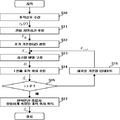
도 2는 본 발명에 분산 MIMO 레이더 시스템에서 반복 연산을 통해 표적을 추정하는 방법을 나타낸 순서도.
도 3은 본 발명에서 제안한 반복 연산을 통한 표적 추정기법과 기존의 테일러 선형 근사 추정 기법의 추정 평균 제곱근 오차(MSE) 추정 기법의 추정 결과를 비교한 도면. 1 is a configuration diagram of a distributed MIMO radar system according to an embodiment of the present invention;
FIG. 2 is a flowchart showing a method of estimating a target through repetitive calculation in a distributed MIMO radar system according to the present invention. FIG.
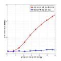
FIG. 3 is a diagram comparing the estimation results of the estimated mean square error (MSE) estimation technique of the conventional Taylor linear approximation estimation technique with the target estimation technique through the iterative calculation proposed in the present invention.
본 발명의 실시예는 여러 가지 형태로 변형될 수 있으며, 본 발명의 범위가 아래에서 서술하는 실시예로 인해 한정되어지는 것으로 해석되어서는 안된다. 여기서 사용되는 기술적이거나 과학적인 용어를 포함한 모든 용어들은 당업계에서 평균적인 지식을 가진 자에 의해 일반적으로 이해되는 것과 동일한 의미를 가지고 있다. The embodiments of the present invention can be modified into various forms and the scope of the present invention should not be interpreted as being limited by the embodiments described below. All terms including technical and scientific terms used herein have the same meaning as commonly understood by one of ordinary skill in the art.
본 발명은 분산(Distributed) MIMO 레이더 환경에서 TDoA 정보를 이용하여 표적의 위치를 추정하는 기법에 관한 것으로, 반복적 연산을 통해 표적의 위치와 근접한 테일러 근사 방정식을 추적하고 이를 통해 정밀한 표적의 위치를 제공하는 기법을 제공함으로써 도래시간차(time difference of arrival : TDoA) 정보 방정식의 비선형성 문제를 해결할 수 있는 방안을 제안한다. The present invention relates to a technique of estimating a position of a target using TDoA information in a distributed MIMO radar environment, and iteratively estimates Taylor approximation equation close to the position of the target, thereby providing a precise target position We propose a method to solve the nonlinearity problem of time difference of arrival (TDoA) information equation.
이하 첨부된 도면을 참조하여 본 발명의 실시예를 상세히 설명한다.Hereinafter, embodiments of the present invention will be described in detail with reference to the accompanying drawings.
도 1은 본 발명의 실시예에 따른 분산 MIMO 레이더 시스템의 개략적인 구성도이고, 도 2는 본 발명에 분산 MIMO 레이더 시스템에서 반복 연산을 통한 표적 추정 방법을 나타낸 순서도이다. FIG. 1 is a schematic block diagram of a distributed MIMO radar system according to an embodiment of the present invention, and FIG. 2 is a flowchart illustrating a target estimation method using an iterative operation in a distributed MIMO radar system according to the present invention.
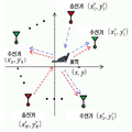
도 1을 참조하면, 본 발명에 따른 분산 MIMO 레이더 시스템은 M개의 송신기, N개의 수신기 및 표적이 2차원 평면에 임의로 분산 배치되어 있다. 이때, 상기 M개의 송신기는 ![]()
![]()
![]()
![]()
![]()
![]()
![]()
![]()
상기와 같은 분산 배치 구조에서 도 2에 도시된 바와같이, 복수의 송신기가 서로 직교하는 전송 신호 ![]()
![]()
![]()
![]()
[수학식 1][Equation 1]
![]()
![]()
여기서 ![]()
![]()
![]()
![]()
![]()
![]()
![]()
![]()
![]()
![]()
![]()
![]()
[수학식 2]&Quot; (2) "
![]()
![]()
여기서 c는 빛의 속도이다. Where c is the speed of light.
상기 수학식 1로부터 최대우 추정(Maximum Likelihood Estimation : MLE) 기법을 이용하여 전파 지연시간(![]()
![]()
![]()
![]()
![]()
![]()
![]()
![]()
![]()
![]()
[수학식 3]&Quot; (3) "
![]()
![]()
상기 수학식 3은 표적의 위치인 x와 y에 대하여 선형 방정식의 형태를 가지지 않으므로 일반적인 추정기법으로는 표적의 위치를 추정할 수 없다. 따라서 임의의 기준점 ![]()
![]()
![]()
![]()
[수학식 4]&Quot; (4) "
![]()
![]()
상기 수학식 4의 선형 근사 방적식에서 ![]()
![]()
![]()
![]()
![]()
![]()
[수학식 5]&Quot; (5) "

상기 수학식 4는 선형 방정식이므로 기존의 추정 기법을 이용하여 표적 추정이 가능하지만 상기 기준점 ![]()
![]()
따라서, 본 발명은 추정된 전파 지연시간(![]()
![]()
도 2에 도시된 바와같이, 먼저, 수신기는 기준점을 업데이트하여 반복 연산하기 위하여 초기 기준점(값)을 설정한다(S12). 일 실시예로 상기 초기 기준점(값)은 ![]()
![]()
![]()
![]()
![]()
![]()
[수학식 6]&Quot; (6) "
![]()
![]()
![]()
![]()
수학식 6에서 ![]()
![]()
![]()
![]()
![]()
![]()
![]()
![]()
![]()
![]()
[수학식 7]&Quot; (7) "

따라서, 상기 수학식 6에 도시된 선형 근사 방정식의 행렬식에 최소자승 (Least Square : LS) 추정 기법을 적용하면, 수학식 8과 같이 i번째 표적 위치의 추정 결과를 얻을 수 있다(S14).Therefore, by applying a Least Square (LS) estimation method to the determinant of the linear approximation equation shown in Equation (6), the estimation result of the i-th target position can be obtained as shown in Equation (8).
[수학식 8]&Quot; (8) "
![]()
![]()
이어서 i가 연산 반복 횟수 P보다 큰지 체크하여(S15), 작은 경우에는 다음 연산을 위한 i+1번째 기준점을 얻기 위하여 수학식 9와 같이 i번째 표적 위치의 추정 결과에 대하여 선형 근사 오차를 정의한다.Next, it is checked whether i is greater than the number of repetitions of operation P (S15). If it is small, a linear approximation error is defined with respect to the estimation result of the i-th target position as shown in equation (9) .
[수학식 9]&Quot; (9) "

상기 수학식 9와 같이 정의된 선형 근사 오차 방정식의 절대값을 최소로 만드는 ![]()
![]()
![]()
![]()
![]()
![]()
[수학식 10]&Quot; (10) "

즉, 수학식 10의 연립방정식을 동시에 만족시키는 새로운(i+1번째) 기준점 (![]()
![]()
[수학식 11]&Quot; (11) "
![]()
![]()
따라서, 본 발명은 수학식 11을 통해 얻어진 i+1번째 기준점을 이용하여 상술한 연산(S13~S14)을 수행함으로써 이전 보다 실제 표적에 더 근접하는 표적 위치의 추정 값을 얻을 수 있고, 같은 방법으로 P회의 반복 연산이 모두 수행되면 다음의 수학식 12와 같이 본 발명에서 제안된 반복 연산을 이용한 표적 위치 추정의 결과 ![]()
![]()
[수학식 12]&Quot; (12) "
![]()
![]()
도 3은 본 발명에서 제안한 반복 연산 추정기법과 기존의 테일러 선형 근사 추정 기법의 추정 평균 제곱근 오차(MSE) 비교를 나타낸 그래프이다, FIG. 3 is a graph showing a comparison of estimated mean square error (MSE) of the conventional iterative linear approximation estimation technique and the iterative operation estimation technique proposed in the present invention.
도 3에 도시된 바와같이, 반복 연산을 통해 위의 수학식 12과 같이 얻어진 표적 위치의 추정 결과와 초기 기준값에 의존하는 기존 테일러 선형 근사 추정 기법을 통해 얻어진 표적 위치의 추정 결과의 성능을 비교하기 위하여, 초기 기준값과 실제 표적간의 거리 대비 추정 결과의 거리 오차를 시뮬레이션하였다. As shown in FIG. 3, the performance of the estimation result of the target position obtained through the iterative calculation and the estimation result of the target position obtained by the conventional Taylor linear approximation estimation technique depending on the initial reference value is compared In order to simulate the distance error between the initial reference value and the actual target versus the estimated result.
도 3에서 확인할 수 있듯이 초기 기준값이 실제 표적과 멀어질수록 기존의 테일러 선형 근사 추정기법은 거리 오차가 증가하는데 반해 본 발명에서 제안된 반복 연산 추정기법은 거리 오차가 거의 증가하지 않는 모습을 확인할 수 있다.As can be seen from FIG. 3, as the initial reference value becomes farther away from the actual target, the conventional Taylor linear approximation estimation technique increases the distance error, whereas the iterative calculation estimation technique of the present invention shows that the distance error hardly increases have.
상술한 바와같이, 본 발명은 분산(Distributed) MIMO 레이더 시스템에서 초기 기준점(값)에서 테일러 선형 근사 추정 기법을 이용하여 표적 위치의 추정 결과를 도출한 후, 상기 도출된 표적 위치의 추정 결과의 선형 근사 오차를 최소화할 수 있는 새로운 기준점을 도출하여 업데이트한 후 상기 업데이트된 새로운 기준점(값)에서 테일러 선형 근사 추정 기법을 이용하여 표적 위치의 추정 결과를 도출하는 연산을 기설정된 횟수(P)만큼 반복적으로 수행한다. As described above, the present invention derives the estimation result of the target position using the Taylor linear approximation estimation technique at the initial reference point (value) in the distributed MIMO radar system, A new reference point that can minimize the approximation error is updated and updated, and an operation of deriving the estimation result of the target position using the Taylor linear approximation estimation technique at the updated new reference point (value) is repeated by a predetermined number (P) .
따라서, 본 발명은 기준점 갱신을 통한 반복적 연산을 통하여 표적의 위치와 근접한 테일러 근사 방정식을 추적하고 이를 통하여 정밀한 표적의 위치를 제공함으로써 기존 기술들이 극복하지 못했던 TDoA 정보 방정식의 비선형성 문제를 용이하게 해결할 수 있는 효과가 있다. Accordingly, the present invention easily tracks the nonlinearity problem of the TDoA information equation which has not been overcome by existing technologies by tracking the Taylor approximation equation close to the position of the target through repetitive computation by updating the reference point and providing the position of the precise target through the Taylor approximation equation There is an effect that can be.
전술한 본 발명은, 프로그램이 기록된 매체에 컴퓨터가 읽을 수 있는 코드로서 구현하는 것이 가능하다. 컴퓨터가 읽을 수 있는 매체는, 컴퓨터 시스템에 의하여 읽혀질 수 있는 데이터가 저장되는 모든 종류의 기록장치를 포함한다. 또한, 상기 컴퓨터는 제어부를 포함할 수도 있다. 따라서, 상기의 상세한 설명은 모든 면에서 제한적으로 해석되어서는 아니되고 예시적인 것으로 고려되어야 한다. 본 발명의 범위는 첨부된 청구항의 합리적 해석에 의해 결정되어야 하고, 본 발명의 등가적 범위 내에서의 모든 변경은 본 발명의 범위에 포함된다.The present invention described above can be embodied as computer-readable codes on a medium on which a program is recorded. The computer readable medium includes all kinds of recording devices in which data that can be read by a computer system is stored. In addition, the computer may include a control unit. Accordingly, the above description should not be construed in a limiting sense in all respects and should be considered illustrative. The scope of the present invention should be determined by rational interpretation of the appended claims, and all changes within the scope of equivalents of the present invention are included in the scope of the present invention.
Claims (8)
상기 표적으로 서로 직교하는 전송 신호를 송신하는 복수의 송신기; 및
상기 복수의 송신기에서 전송되어 표적을 경유한 신호를 수신하여, 표적의 초기 기준점에서 테일러 선형 근사 추정 기법을 이용하여 표적 위치를 추정하는 복수의 수신기;로 구성되어,
상기 각 수신기는
상기 추정된 표적 위치의 선형 근사 오차 방정식을 근거로 해당 방정식의 절대값을 최소로 만드는 새로운 표적 기준점을 업데이트하여 상기 테일러 선형 근사 추정 기법에 의한 표적 위치 추정을 반복적으로 수행하는 것을 특징으로 하는 분산 MIMO 레이더 시스템. A distributed MIMO radar system in which a plurality of transmitters, a target, and a plurality of receivers are distributed on a two-dimensional plane,
A plurality of transmitters for transmitting a transmission signal orthogonal to the target; And
A plurality of receivers for receiving a signal transmitted from the plurality of transmitters and passing through a target and estimating a target position using Taylor linear approximation at an initial reference point of the target,
Each receiver
And a new target reference point that minimizes the absolute value of the equation based on the linear approximate error equation of the estimated target position is updated so that the target position estimation by the Taylor linear approximation estimation technique is repeatedly performed. Radar system.
상기 정의된 선형 근사 오차 방정식을 제곱한 수식에서 표적 기준점에 대한 편도함수를 계산하여 상기 편도함수를 제로로 만드는 새로운 표적 기준점을 도출하는 것을 특징으로 하는 분산 MIMO 레이더 시스템. The receiver of claim 1, wherein each receiver
Wherein a new target reference point for deriving the one-way function to zero is calculated by calculating a one-way function for a target reference point in an equation obtained by squaring the defined linear approximation error equation.
기 설정된 횟수만큼 반복적으로 수행되는 것을 특징으로 하는 분산 MIMO 레이더 시스템. 2. The method of claim 1,
And the MIMO radar system is repeatedly performed a predetermined number of times.
반복 횟수가 증가할수록 실제 표적에 더 근접하는 것을 특징으로 하는 분산 MIMO 레이더 시스템.2. The method of claim 1, wherein the estimated target position is
And as the number of repetitions increases, it becomes closer to an actual target.
복수의 송신기에서 전송되어 표적을 경유한 신호를 수신하는 단계;
표적의 초기 기준점에서 수신신호에 테일러 선형 근사 추정 기법을 적용하여 표적위치를 추정하는 단계;
상기 추정된 표적 위치의 선형 근사 오차 방정식을 정의하는 단계;
상기 정의된 선형 근사 오차 방정식의 절대값을 최소로 만드는 새로운 표적 기준점을 도출하여 업데이트하는 단계; 및
상기 업데이트된 새로운 표적 기준점에서 테일러 선형 근사 추정 기법을 이용한 표적 위치 추정을 반복적으로 수행하는 단계;를 포함하는 것을 특징으로 하는 분산 MIMO 레이더 시스템의 표적 위치 추정방법. A method for estimating a target position in a distributed MIMO radar system in which a plurality of transmitters, a target, and a plurality of receivers are distributed on a two-dimensional plane,
Receiving signals transmitted from a plurality of transmitters via a target;
Estimating a target position by applying Taylor linear approximation to the received signal at an initial reference point of the target;
Defining a linear approximation error equation of the estimated target position;
Deriving and updating a new target reference point that minimizes the absolute value of the linear approximation error equation defined above; And
And repeatedly performing a target position estimation using the Taylor linear approximation estimation method at the updated new target reference point.
상기 정의된 선형 근사 오차 방정식을 제곱한 수식에서 표적 기준점에 대한 편도함수를 계산하는 단계; 및
상기 계산된 편도함수를 제로로 만드는 새로운 표적 기준점을 도출하는 단계;를 포함하는 것을 특징으로 하는 분산 MIMO 레이더 시스템의 표적 위치 추정방법. 6. The method of claim 5, wherein deriving the new target reference point
Calculating a partial derivative of the linear approximation error equation with respect to a target reference point in an equation obtained by squaring the linear approximation error equation; And
And deriving a new target reference point that makes the calculated one way function zero. ≪ Desc / Clms Page number 19 >
기 설정된 횟수만큼 반복적으로 수행되며,
상기 추정된 표적 위치는 반복 횟수가 증가할수록 실제 표적에 더 근접하는 것을 특징으로 하는 분산 MIMO 레이더 시스템의 표적 위치 추정방법. 6. The method of claim 5,
Is repeatedly performed a predetermined number of times,
Wherein the estimated target location is closer to an actual target as the number of iterations increases. ≪ Desc / Clms Page number 19 >
최대우 추정 기법을 이용하여 수신신호의 전파 지연시간을 추정하는 단계;
초기 기준점에서 테일러 선형 근사를 이용하여 상기 추정된 전파 지연시간에 대한 선형 근사 방정식을 도출하는 단계;
상기 도출된 전파 지연시간의 선형 근사 방정식을 모든 송·수신기에 대한 행렬식으로 도출하는 단계; 및
상기 도출된 선형 근사 방정식의 행렬식에 최소자승 추정 기법을 적용하여 표적위치를 추정하는 단계;를 포함하는 것을 특징으로 하는 분산 MIMO 레이더 시스템의 표적 위치 추정방법.6. The method of claim 5, wherein estimating the target position comprises:
Estimating a propagation delay time of a received signal using a maximum likelihood estimation technique;
Deriving a linear approximation equation for the estimated propagation delay time using Taylor linear approximation at an initial reference point;
Deriving a linear approximation equation of the derived propagation delay time as a determinant for all transmitters and receivers; And
Estimating a target position by applying a least squares estimation technique to the determinant of the derived linear approximation equation; and estimating a target position by applying a least square estimation technique to the determinant of the derived linear approximation equation.
Priority Applications (1)
| Application Number | Priority Date | Filing Date | Title |
|---|---|---|---|
| KR1020160051777A KR101760392B1 (en) | 2016-04-27 | 2016-04-27 | Distributed mimo radar system and method of target position estimation thereof |
Applications Claiming Priority (1)
| Application Number | Priority Date | Filing Date | Title |
|---|---|---|---|
| KR1020160051777A KR101760392B1 (en) | 2016-04-27 | 2016-04-27 | Distributed mimo radar system and method of target position estimation thereof |
Publications (1)
| Publication Number | Publication Date |
|---|---|
| KR101760392B1 true KR101760392B1 (en) | 2017-07-21 |
Family
ID=59462660
Family Applications (1)
| Application Number | Title | Priority Date | Filing Date |
|---|---|---|---|
| KR1020160051777A KR101760392B1 (en) | 2016-04-27 | 2016-04-27 | Distributed mimo radar system and method of target position estimation thereof |
Country Status (1)
| Country | Link |
|---|---|
| KR (1) | KR101760392B1 (en) |
Cited By (3)
| Publication number | Priority date | Publication date | Assignee | Title |
|---|---|---|---|---|
| KR20190019755A (en) * | 2017-08-18 | 2019-02-27 | 국방과학연구소 | Method, apparatus and system for target object localization using a distributed Multiple Input Multiple Output radar system |
| CN110687508A (en) * | 2019-10-12 | 2020-01-14 | 内蒙古工业大学 | Method for correcting monitoring data of micro-varying radar |
| KR102643405B1 (en) | 2023-08-31 | 2024-03-05 | 한화시스템(주) | System and method for detecting multi-target based on image processing in radar |
Citations (3)
| Publication number | Priority date | Publication date | Assignee | Title |
|---|---|---|---|---|
| JP2009186456A (en) * | 2008-02-06 | 2009-08-20 | Mitsubishi Electric Research Laboratories Inc | Method for estimating delay in toa (time of arrival) of transmit signal |
| JP4644197B2 (en) * | 2003-08-14 | 2011-03-02 | センシス コーポレーション | Target location method and apparatus using TDOA distributed antenna |
| KR101615151B1 (en) * | 2015-03-04 | 2016-04-25 | 국방과학연구소 | Method of 3-D MIMO InISAR Imaging for a Stealth Target |
-
2016
- 2016-04-27 KR KR1020160051777A patent/KR101760392B1/en active IP Right Grant
Patent Citations (3)
| Publication number | Priority date | Publication date | Assignee | Title |
|---|---|---|---|---|
| JP4644197B2 (en) * | 2003-08-14 | 2011-03-02 | センシス コーポレーション | Target location method and apparatus using TDOA distributed antenna |
| JP2009186456A (en) * | 2008-02-06 | 2009-08-20 | Mitsubishi Electric Research Laboratories Inc | Method for estimating delay in toa (time of arrival) of transmit signal |
| KR101615151B1 (en) * | 2015-03-04 | 2016-04-25 | 국방과학연구소 | Method of 3-D MIMO InISAR Imaging for a Stealth Target |
Cited By (4)
| Publication number | Priority date | Publication date | Assignee | Title |
|---|---|---|---|---|
| KR20190019755A (en) * | 2017-08-18 | 2019-02-27 | 국방과학연구소 | Method, apparatus and system for target object localization using a distributed Multiple Input Multiple Output radar system |
| KR102040178B1 (en) * | 2017-08-18 | 2019-11-04 | 국방과학연구소 | Method, apparatus and system for target object localization using a distributed Multiple Input Multiple Output radar system |
| CN110687508A (en) * | 2019-10-12 | 2020-01-14 | 内蒙古工业大学 | Method for correcting monitoring data of micro-varying radar |
| KR102643405B1 (en) | 2023-08-31 | 2024-03-05 | 한화시스템(주) | System and method for detecting multi-target based on image processing in radar |
Similar Documents
| Publication | Publication Date | Title |
|---|---|---|
| CN108717184B (en) | Error correction-based DOA and TOA combined single-station passive positioning method | |
| KR101260647B1 (en) | Wireless localization method based on an efficient multilateration algorithm over a wireless sensor network and a recording medium in which a program for the method is recorded | |
| Liang et al. | Robust MIMO radar target localization via nonconvex optimization | |
| KR101760392B1 (en) | Distributed mimo radar system and method of target position estimation thereof | |
| US11456809B2 (en) | Position estimation method for estimating position of interference signal source and position estimation system for performing the method | |
| CN108387876B (en) | External radiation source radar network double-base-distance error registration method based on CTLS | |
| JP2018084575A (en) | Arrival angle detection system and method | |
| CN108152789B (en) | Utilize the passive track-corelation data correlation and localization method of RSS information | |
| WO2016112758A1 (en) | Method and apparatus for locating terminal | |
| KR20120115895A (en) | Wireless localization method using 4 or more anchor nodes based on rssi at indoor environment and a recording medium in which a program for the method is recorded | |
| CN105471777A (en) | Visible light channel estimation method and system | |
| US20160182164A1 (en) | Signal Strength Distribution Establishing Method and Wireless Positioning System | |
| KR101988109B1 (en) | Method for estimating position of signal source using distance estimation in mimo system | |
| KR101627419B1 (en) | Method for estmating location of mobile node and apparatus thereof | |
| CN112887901A (en) | Convex optimization target positioning method based on quantitative TOA measurement | |
| KR101252531B1 (en) | Location tracking apparatus using adaptive kalman filter | |
| Xiong et al. | Data-selective least squares methods for elliptic localization with NLOS mitigation | |
| KR102248758B1 (en) | Hybrid RSS/AOA Localization using Approximated Weighted Least Square in Wireless Sensor Networks | |
| JP5583170B2 (en) | Scatterer position estimation apparatus, scatterer position estimation method, and program | |
| CN102628931B (en) | Linear relation-based time difference positioning algorithm with high precision | |
| KR101432932B1 (en) | Method and apparatus for estimating target in jammer scenario | |
| KR101689628B1 (en) | Apparatus and method for estimating passive emitter location | |
| Zamani et al. | Compressive sensing for elliptic localization in MIMO radars | |
| KR20180047194A (en) | A location of a radio wave disturbance source and the transmission power estimation apparatus | |
| CN113359095B (en) | Coherent passive MIMO radar Clarithrome boundary calculation method |
Legal Events
| Date | Code | Title | Description |
|---|---|---|---|
| E701 | Decision to grant or registration of patent right | ||
| GRNT | Written decision to grant |