KR101727095B1 - Light application apparatus for applying light to an object - Google Patents
Light application apparatus for applying light to an object Download PDFInfo
- Publication number
- KR101727095B1 KR101727095B1 KR1020127004191A KR20127004191A KR101727095B1 KR 101727095 B1 KR101727095 B1 KR 101727095B1 KR 1020127004191 A KR1020127004191 A KR 1020127004191A KR 20127004191 A KR20127004191 A KR 20127004191A KR 101727095 B1 KR101727095 B1 KR 101727095B1
- Authority
- KR
- South Korea
- Prior art keywords
- light
- sensing
- processing
- light source
- subject
- Prior art date
Links
Images


Classifications
-
- A—HUMAN NECESSITIES
- A61—MEDICAL OR VETERINARY SCIENCE; HYGIENE
- A61B—DIAGNOSIS; SURGERY; IDENTIFICATION
- A61B18/00—Surgical instruments, devices or methods for transferring non-mechanical forms of energy to or from the body
- A61B18/18—Surgical instruments, devices or methods for transferring non-mechanical forms of energy to or from the body by applying electromagnetic radiation, e.g. microwaves
- A61B18/20—Surgical instruments, devices or methods for transferring non-mechanical forms of energy to or from the body by applying electromagnetic radiation, e.g. microwaves using laser
- A61B18/203—Surgical instruments, devices or methods for transferring non-mechanical forms of energy to or from the body by applying electromagnetic radiation, e.g. microwaves using laser applying laser energy to the outside of the body
-
- A—HUMAN NECESSITIES
- A61—MEDICAL OR VETERINARY SCIENCE; HYGIENE
- A61N—ELECTROTHERAPY; MAGNETOTHERAPY; RADIATION THERAPY; ULTRASOUND THERAPY
- A61N5/00—Radiation therapy
- A61N5/06—Radiation therapy using light
- A61N5/0613—Apparatus adapted for a specific treatment
- A61N5/0616—Skin treatment other than tanning
-
- A—HUMAN NECESSITIES
- A61—MEDICAL OR VETERINARY SCIENCE; HYGIENE
- A61B—DIAGNOSIS; SURGERY; IDENTIFICATION
- A61B18/00—Surgical instruments, devices or methods for transferring non-mechanical forms of energy to or from the body
- A61B18/18—Surgical instruments, devices or methods for transferring non-mechanical forms of energy to or from the body by applying electromagnetic radiation, e.g. microwaves
- A61B18/20—Surgical instruments, devices or methods for transferring non-mechanical forms of energy to or from the body by applying electromagnetic radiation, e.g. microwaves using laser
-
- A—HUMAN NECESSITIES
- A61—MEDICAL OR VETERINARY SCIENCE; HYGIENE
- A61N—ELECTROTHERAPY; MAGNETOTHERAPY; RADIATION THERAPY; ULTRASOUND THERAPY
- A61N5/00—Radiation therapy
- A61N5/06—Radiation therapy using light
- A61N5/067—Radiation therapy using light using laser light
-
- A—HUMAN NECESSITIES
- A61—MEDICAL OR VETERINARY SCIENCE; HYGIENE
- A61B—DIAGNOSIS; SURGERY; IDENTIFICATION
- A61B17/00—Surgical instruments, devices or methods, e.g. tourniquets
- A61B2017/00017—Electrical control of surgical instruments
- A61B2017/00022—Sensing or detecting at the treatment site
- A61B2017/00057—Light
-
- A—HUMAN NECESSITIES
- A61—MEDICAL OR VETERINARY SCIENCE; HYGIENE
- A61B—DIAGNOSIS; SURGERY; IDENTIFICATION
- A61B18/00—Surgical instruments, devices or methods for transferring non-mechanical forms of energy to or from the body
- A61B2018/00315—Surgical instruments, devices or methods for transferring non-mechanical forms of energy to or from the body for treatment of particular body parts
- A61B2018/00452—Skin
- A61B2018/00476—Hair follicles
-
- A—HUMAN NECESSITIES
- A61—MEDICAL OR VETERINARY SCIENCE; HYGIENE
- A61B—DIAGNOSIS; SURGERY; IDENTIFICATION
- A61B18/00—Surgical instruments, devices or methods for transferring non-mechanical forms of energy to or from the body
- A61B2018/00636—Sensing and controlling the application of energy
-
- A—HUMAN NECESSITIES
- A61—MEDICAL OR VETERINARY SCIENCE; HYGIENE
- A61B—DIAGNOSIS; SURGERY; IDENTIFICATION
- A61B18/00—Surgical instruments, devices or methods for transferring non-mechanical forms of energy to or from the body
- A61B2018/00636—Sensing and controlling the application of energy
- A61B2018/00904—Automatic detection of target tissue
-
- A—HUMAN NECESSITIES
- A61—MEDICAL OR VETERINARY SCIENCE; HYGIENE
- A61B—DIAGNOSIS; SURGERY; IDENTIFICATION
- A61B18/00—Surgical instruments, devices or methods for transferring non-mechanical forms of energy to or from the body
- A61B18/18—Surgical instruments, devices or methods for transferring non-mechanical forms of energy to or from the body by applying electromagnetic radiation, e.g. microwaves
- A61B18/20—Surgical instruments, devices or methods for transferring non-mechanical forms of energy to or from the body by applying electromagnetic radiation, e.g. microwaves using laser
- A61B2018/2065—Multiwave; Wavelength mixing, e.g. using four or more wavelengths
-
- A—HUMAN NECESSITIES
- A61—MEDICAL OR VETERINARY SCIENCE; HYGIENE
- A61N—ELECTROTHERAPY; MAGNETOTHERAPY; RADIATION THERAPY; ULTRASOUND THERAPY
- A61N5/00—Radiation therapy
- A61N5/06—Radiation therapy using light
- A61N2005/0626—Monitoring, verifying, controlling systems and methods
-
- A—HUMAN NECESSITIES
- A61—MEDICAL OR VETERINARY SCIENCE; HYGIENE
- A61N—ELECTROTHERAPY; MAGNETOTHERAPY; RADIATION THERAPY; ULTRASOUND THERAPY
- A61N5/00—Radiation therapy
- A61N5/06—Radiation therapy using light
- A61N2005/0626—Monitoring, verifying, controlling systems and methods
- A61N2005/0629—Sequential activation of light sources
-
- A—HUMAN NECESSITIES
- A61—MEDICAL OR VETERINARY SCIENCE; HYGIENE
- A61N—ELECTROTHERAPY; MAGNETOTHERAPY; RADIATION THERAPY; ULTRASOUND THERAPY
- A61N5/00—Radiation therapy
- A61N5/06—Radiation therapy using light
- A61N2005/0635—Radiation therapy using light characterised by the body area to be irradiated
- A61N2005/0642—Irradiating part of the body at a certain distance
-
- A—HUMAN NECESSITIES
- A61—MEDICAL OR VETERINARY SCIENCE; HYGIENE
- A61N—ELECTROTHERAPY; MAGNETOTHERAPY; RADIATION THERAPY; ULTRASOUND THERAPY
- A61N5/00—Radiation therapy
- A61N5/06—Radiation therapy using light
- A61N2005/065—Light sources therefor
- A61N2005/0651—Diodes
- A61N2005/0652—Arrays of diodes
Abstract
본 발명은 피사체(3)에 광을 조사하는 광 조사 장치(1)에 관한 것이다. 광원(4)은 피사체(3)로 결합되는 처리광(2)과 감지광(5)을 발생시킨다. 광 검출기(8)는 피사체(3)를 떠난 후의 감지광(5)을 검출하고, 제어부(9)는 처리 시간 구간에서는 처리광(2)을 그리고 감지 시간 구간에서는 감지광(5)을 교대로 발생시키도록 광원(4)을 제어한다. 처리광과 감지광이 교대로 발생되므로, 처리광과 감지광의 발생은 분리되고, 즉, 처리광이 처리를 위해 최적화될 수 있고, 감지광이 감지를 위해 최적화 될 수 있다. 이것은 피사체를 감지하는 품질, 따라서, 피사체의 특성에 의해 광의 조사를 제어하는 품질을 개선시킨다.The present invention relates to a light irradiation apparatus (1) for irradiating light onto a subject (3). The light source 4 generates the processing light 2 and the sensing light 5 that are coupled to the object 3. The photodetector 8 detects the detection light 5 after leaving the subject 3 and the control unit 9 outputs the processing light 2 in the processing time interval and the detection light 5 in the detection time interval alternately And controls the light source 4 to generate the light. Since the processing light and the sensing light are alternately generated, the generation of the processing light and the sensing light can be separated, that is, the processing light can be optimized for processing, and the sensing light can be optimized for sensing. This improves the quality of detecting the subject, and thus the quality of controlling the irradiation of light by the characteristics of the subject.
Description
본 발명은 피사체에 광을 조사하는 광 조사 장치, 광 조사 방법, 및 컴퓨터 프로그램에 관한 것이다.Field of the Invention [0002] The present invention relates to a light irradiation apparatus, a light irradiation method, and a computer program for irradiating light onto a subject.
WO 2007/106339 A2에서는 피부를 치료하는 예를 들어, 피부에서 체모를 제거하기 위하여 사람의 피부에 광을 조사하는 광 조사 장치를 개시하고 있다. 실시예에 있어서, 피부를 치료하기 위하여 하나 이상의 발광 다이오드로부터의 광이 사용되며, 일부 광은 표피, 특히, 센서에 다시 반사되기 전에 진피를 통과한다. 전자 제어 시스템은 장치의 동작을 제어하기 위해 센서의 출력을 사용한다. 이것은 피부의 특성에 따라 장치의 동작을 제어할 수 있도록 한다.WO 2007/106339 A2 discloses a light irradiation apparatus for treating skin, for example, for irradiating human skin with light to remove hair from the skin. In an embodiment, light from one or more light emitting diodes is used to treat the skin, and some light passes through the dermis before it is reflected back to the epidermis, particularly the sensor. The electronic control system uses the output of the sensor to control the operation of the device. This allows the operation of the device to be controlled according to the characteristics of the skin.
본 발명의 목적은 피사체에 광을 조사하는 광 조사 장치를 제공하는 것이며, 피사체의 특성들에 따라 광의 조사의 제어가 개선될 수 있다.An object of the present invention is to provide a light irradiating device for irradiating light to a subject, and the control of the irradiation of light can be improved according to the characteristics of the object.
본 발명의 양태에서, 피사체에 광을 조사하여 체모를 제거하기 위한 광 조사 장치가 제공되며, 상기 피사체는 인간 또는 동물의 피부이며, 상기 광 조사 장치는, In an aspect of the present invention, there is provided a light irradiation apparatus for irradiating light to a subject to remove hair, the subject being a human or animal skin,
피사체를 처리하는 처리광 및 피사체를 감지하는 감지광을 생성하기 위한 광원 - 상기 광원은 처리광과 감지광을 피사체에 결합하도록 구성됨 -, A light source for generating processing light for processing the object and sensing light for sensing the object, the light source being configured to couple the processing light and the sensing light to the object,
피사체를 떠난 후의 감지광을 검출하는 광 검출기, A photodetector for detecting the detection light after leaving the subject,
상기 광원이 처리 시간 구간에서는 처리광을 그리고 감지 시간 구간에서는 감지광을 교대로 생성하도록 상기 광원을 제어하기 위한 제어부 - 상기 제어부는 검출된 감지광으로부터 감지광의 흡수를 판정하고 처리광이 판정된 흡수에 따라 발생되도록 광원을 제어하도록 구성됨 - 를 포함한다.A controller for controlling the light source such that the light source alternately generates the processing light in the processing time interval and the sensing light in the sensing time interval, the controller determines absorption of the sensing light from the detected sensing light, And to control the light source to be generated in accordance with the control signal.
처리광과 감지광이 교대로 발생되기 때문에, 처리광과 감지광의 발생은 분리되고, 즉, 처리광이 처리 목적에 최적화될 수 있고, 감지광이 감지 목적에 최적화될 수 있다. 이것은 피사체를 감지하는 품질 및 피사체의 특성에 따라 광의 조사를 제어하는 품질을 개선하도록 한다.Since the processing light and the sensing light are generated alternately, the generation of the processing light and the sensing light can be separated, that is, the processing light can be optimized for the processing purpose, and the sensing light can be optimized for the sensing purpose. This improves the quality of controlling the irradiation of light according to the quality of the object and the characteristics of the object.
광원은 바람직하게는 고체 광원, 특히, 발광 다이오드, 유기 발광 다이오드, 또는 레이저 다이오드이다.The light source is preferably a solid light source, in particular a light emitting diode, an organic light emitting diode, or a laser diode.
고체 광원은 매우 빠르게 스위칭될 수 있다. 예를 들어, 이는 감지광을 이용하여 피사체를 감지하기 위한 수 밀리세컨드(millisecond) 동안만 처리광을 이용한 피사체의 처리를 중단하도록 하는 것으로서, 즉, 피사체를 처리하는 효율을 훼손하지 않고 피사체를 감지하기 위하여 처리 절차가 중단될 수 있다.The solid state light source can be switched very quickly. For example, this is to stop the processing of the object using the processing light for only a few milliseconds for detecting the object using the detection light, that is, to detect the object without deteriorating the efficiency of processing the object The processing procedure may be interrupted.
처리광은 스펙트럼 방출 및 전력 밀도를 갖는 광이 바람직하며, 이는 더 적은 고통과 더 적은 부작용으로 효율적인 제모를 허용하기 위해 주변의 피부에는 더 적게, 모낭의 멜라닌에 주로 광이 흡수되도록 한다. 처리광은 570-1200 nm 범위의 파장 및 2-30 J/cm2 범위의 에너지 밀도를 갖는 것이 바람직하다.The processed light is preferably light having a spectrum emission and power density, which allows less light to be absorbed into the melanin of the hair follicle, mainly in the surrounding skin, to allow efficient hair removal with less pain and fewer side effects. The processed light preferably has a wavelength in the range of 570-1200 nm and an energy density in the range of 2-30 J / cm 2 .
감지광은 570-1200 nm의 파장 범위 내의 파장 및 처리광의 에너지 밀도와 상이한 에너지 밀도, 특히, 처리광의 에너지 밀도보다 더 작거나, 또는 광원에 의해 생성될 수 있는 최대 에너지 밀도와 동일한 에너지 밀도를 갖는 것이 바람직하다.The sensing light has a wavelength within a wavelength range of 570-1200 nm and an energy density different from the energy density of the processing light, in particular, an energy density equal to the maximum energy density that can be generated by the light source, .
광원은 감지광이 피사체를 진행한 후에 피사체를 떠나도록 감지광을 피사체에 결합하도록 구성된다.The light source is configured to couple the sensing light to the subject so that the sensing light leaves the subject after proceeding to the subject.
광 검출기는 포토다이오드인 것이 바람직하다.The photodetector is preferably a photodiode.
광원이 처리 시간 구간에서는 처리광을, 그리고 감지 시간 구간에서는 감지광을 반복하여 교대로 발생하도록 제어부가 구성될 수 있다. 그러나, 제어부는 감지광을 이용하여 피사체를 감지하기 위해 단 1회만 피사체의 처리를 중단하도록 구성될 수 있으며, 감지 시간 구간은 시간적으로 제1 처리 시간 구간과 제2 처리 시간 구간 사이에 위치된다.The control unit may be configured so that the light source repeatedly generates the processing light in the processing time interval and the sensing light in the sensing time interval. However, the control unit may be configured to stop the processing of the subject only once to detect the subject using the sensing light, and the sensing time interval is temporally located between the first processing time interval and the second processing time interval.
고체 광원은 매우 빠르게 스위칭될 수 있다. 예를 들어, 이는 감지광으로 피사체를 감지하기 위하여 수 밀리세컨드 동안만 처리광을 이용한 피사체의 처리를 중단시키는 것으로서, 즉, 처리 절차는 피사체를 처리하는 효율을 훼손하지 않고 피사체를 감지하기 위하여 중단될 수 있다.The solid state light source can be switched very quickly. For example, this is to stop the processing of the object using the processing light for only a few milliseconds in order to detect the object with the detection light, that is, the processing procedure is stopped to detect the object without deteriorating the efficiency of processing the object. .
광원은 수직 공진 표면 발광 레이저(vertical-cavity surface-emitting laser; VCSEL)를 포함하는 것이 바람직하다. VCSEL은 전술한 파장 범위에서 고효율을 가지며, 사람의 피부 상에 체모를 제거하기 위해 광 조사 장치의 조사를 촉진하는 공간 방출 특성을 갖는다.The light source preferably includes a vertical-cavity surface-emitting laser (VCSEL). The VCSEL has high efficiency in the above-mentioned wavelength range and has a spatial emission characteristic that promotes irradiation of the light irradiation apparatus to remove hair on human skin.
피사체의 처리는 사람의 피부 치료, 특히, 피부로부터 체모를 제거하는 것이 바람직하다.It is preferable that the treatment of the subject is to treat human skin, in particular to remove hair from the skin.
바람직하게, 광원은 발광 소자의 어레이, 특히, VCSEL들의 어레이를 포함하며, 이는 평면 배치로 제공되는 것이 바람직하다.Preferably, the light source comprises an array of luminous means, in particular an array of VCSELs, which is preferably provided in a planar arrangement.
광 검출기는 발광 소자의 어레이 옆에 배치되는 것이 바람직하다. 발광 소자들 및 광 검출기의 이러한 배치는 광 검출기와 각각의 발광 소자 사이의 거리의 변화를 증가시킨다. 예를 들어, 발광 소자들이 서브 그룹에 배치되면, 발광 소자들의 어레이 앞이나 뒤에 배치되는 광 검출기는 광 검출기와 발광 소자들의 각각의 서브 그룹과의 거리의 변화를 최대화한다. 이 서브 그룹들은 감지광을 방출하고, 이는 피사체로 결합되고, 피사체를 진행하여, 광 검출기에 의해 마침내 검출되면, 서로 다른 서브 그룹들로부터 방출되는 감지광은 서로 다른 거리로 피사체를 통과한다. 따라서, 광 검출기에 의해 검출되고 서로 다른 서브 그룹들로부터 방출되는 감지광은 피사체에 의해 상이하게 영향을 받게 되며, 이는 광원을 제어하기 위해, 특히, 광원에 의한 처리광의 발생을 제어하는 데 사용될 수 있는 정보의 다양성을 증가시키게 된다.The photodetector is preferably disposed next to the array of light emitting elements. This arrangement of light emitting elements and the photodetector increases the variation of the distance between the photodetector and each light emitting element. For example, if the light emitting elements are placed in subgroups, the photodetectors placed before or after the array of light emitting elements maximize the change in distance between the photodetector and each subgroup of light emitting elements. These subgroups emit the sensing light, which is coupled to the subject, travels the subject, and is finally detected by the photodetector, the sensing light emitted from the different subgroups passes through the subject at different distances. Thus, the sensing light detected by the photodetector and emitted from different subgroups is affected differently by the subject, which can be used to control the light source, in particular, to control the generation of processing light by the light source. Thereby increasing the diversity of information available.
광원이 발광 소자들의 어레이를 포함하는 것이 더 바람직하며, 발광 소자들의 공간 밀도는 어레이 내에서보다 어레이의 단부에서 더 크다. 발광 소자들의 어레이가 발광 소자들의 2차원 어레이라면, 어레이의 단부는 어레이의 엣지로 간주될 수 있다.It is further preferred that the light source comprises an array of light emitting elements, wherein the spatial density of the light emitting elements is greater at the end of the array than in the array. If the array of light emitting elements is a two-dimensional array of light emitting elements, the ends of the array can be regarded as the edges of the array.
일반적으로, 처리광이 향하는 피사체의 위치는 단일의 발광 소자가 아닌 수개의 이웃하는 발광 소자들에 의해 영향을 받는다. 발광 소자들의 어레이의 단부에서는, 발광 소자들이 감소된 수의 이웃들을 가지므로, 피사체를 처리하는 데에 사용중인 처리광의 강도는 발광 소자들의 단부에서 감소될 수 있는데, 이는 발광 소자들이 피사체의 각각의 위치에 영향을 덜 미치기 때문이다. 발광 소자들의 어레이의 단부에서, 발광 소자들의 밀도가 어레이 내에서보다 더 크면, 이 더 큰 공간 밀도는 발광 소자들의 어레이의 단부에서의 감소된 처리 효과를 상쇄시킬 수 있다. 특히, 발광 소자들의 어레이의 단부에 배치되는 피사체의 위치가 발광 소자들의 어레이를 기준으로 더 중심에 배치되는 피사체의 위치와 동일한 강도를 수신하도록, 발광 소자들의 어레이의 단부에서의 발광 소자들의 공간 밀도가 구성된다.In general, the position of a subject to which processing light is directed is affected by several neighboring light emitting elements rather than a single light emitting element. At the end of the array of luminous means, the luminous means have a reduced number of neighbors so that the intensity of the processing light used in processing the subject can be reduced at the end of the luminous means, This is because it has less impact on location. At the end of the array of light emitting elements, if the density of the light emitting elements is greater in the array, this larger spatial density can offset the reduced processing effect at the end of the array of light emitting elements. In particular, the spatial density of the light emitting elements at the end of the array of light emitting elements is adjusted so that the position of the object located at the end of the array of light emitting elements receives the same intensity as the position of the object being more centrally located relative to the array of light emitting elements .
광원이 길이 방향의 길이 치수 및 폭 방향의 폭 치수를 갖는 직사각형 형상의 발광 소자들의 어레이를 포함하는 것이 더 바람직하며, 길이 치수는 폭 치수보다 더 크다.It is further preferred that the light source comprises an array of rectangular light emitting elements having a length dimension in the length direction and a width dimension in the width direction, wherein the length dimension is greater than the width dimension.
이 직사각형 형상은 일차원 형상으로서 간주될 수 있다. 길이 치수는 수 센티미터의 범위인 것이 바람직하고, 폭 치수는 수 밀리미터의 범위인 것이 바람직하다. 특히, 길이 치수는 1 cm 초과 3 cm 미만인 것이 바람직하다. 폭 치수는 1 mm 초과 3mm 미만인 것이 바람직하다.This rectangular shape can be regarded as a one-dimensional shape. The length dimension is preferably in the range of a few centimeters, and the width dimension is preferably in the range of several millimeters. In particular, the length dimension is preferably greater than 1 cm and less than 3 cm. The width dimension is preferably greater than 1 mm and less than 3 mm.
피부에 미리 정해진 펄스 길이를 갖는 처리광의 펄스를 조사하는 것이 더 바람직하다. 2차원 직사각형 형상을 갖는 광원이 고정된 위치의 피부 상에 위치한다면, 펄스 길이는 광원이 이 위치상에 스위칭되는 시간 간격의 길이에 의해 결정된다. 1차원 직사각형 형상을 갖는 광원이 폭 방향의 피부를 트래킹(tracking)한다면, 펄스 길이는 트래킹 속도에 의해 분리된 이 폭 방향과 대략 동일하다.It is more preferable to irradiate the skin with a pulse of the processing light having a predetermined pulse length. If the light source having a two-dimensional rectangular shape is located on the skin at a fixed position, the pulse length is determined by the length of the time interval at which the light source is switched on this position. If the light source having a one-dimensional rectangular shape tracks the skin in the width direction, the pulse length is approximately equal to this width direction separated by the tracking speed.
광 검출기가 길이 방향으로 발광 소자들의 어레이 옆에 배치되는 것이 더 바람직하다.It is further preferred that the photodetector is arranged next to the array of light emitting elements in the longitudinal direction.
이것은 광 검출기와 각각의 발광 소자들 사이 특히, 발광 소자들의 어레이가 서브그룹들로 분리되는 경우, 광 검출기와 각각의 서브 그룹들 사이의 거리의 변화를 더 증가시킨다.This further increases the variation of the distance between the photodetector and each of the subgroups, especially when the array of luminous elements is divided into subgroups, between the photodetector and each of the light emitting elements.
이미 전술한 바와 같이, 발광 소자들의 어레이는 서브그룹으로 분리되는 것이 바람직하다. 제어부는 서로 독립적으로 서브그룹을 제어하도록 구성되는 것이 바람직하다. 예를 들어, 제어부는, 원하는 조명 프로파일을 발생시키기 위해 서로 다른 서브그룹들의 발광 소자들이 서로 다른 파장 및/또는 서로 다른 강도의 광을 방출하도록 서로 독립적으로 서브그룹을 제어하도록 구성되는 것이 바람직하다. 바람직하게는, 동일한 서브그룹의 발광 소자들은 동일한 파장 및/또는 동일한 강도를 갖는 광을 방출한다. 광 검출기는 서브그룹의 발광 소자들의 평균 위치에 대해 상이한 거리를 갖는 위치에 배치되는 것이 바람직하다. 또한, 이것은 각각의 서브그룹에 대한 광 검출기의 거리의 변화를 증가시킨다.As already mentioned above, it is preferred that the array of luminous means be divided into subgroups. Preferably, the control unit is configured to control the subgroup independently of each other. For example, the control unit is preferably configured to control the subgroup independently of each other so that the light emitting elements of different subgroups emit light of different wavelengths and / or different intensities to generate a desired illumination profile. Preferably, the light-emitting elements of the same subgroup emit light having the same wavelength and / or the same intensity. Preferably, the photodetectors are disposed at positions having different distances relative to the average position of the light emitting elements of the subgroup. This also increases the variation of the distance of the photodetector for each subgroup.
광원은 서브그룹으로 분리된 발광 소자들의 어레이를 포함하는 것이 바람직하며, 제어부는 오직 하나의 서브그룹이 감지 시간 구간에서 한 번에 감지광을 방출하도록 광원을 제어하도록 구성된다.Preferably, the light source comprises an array of light emitting elements separated into subgroups, and the control unit is configured to control the light source such that only one subgroup emits the sensing light at one time in the sensing time interval.
이것은 광 검출기에 의해 검출되고 서로 다른 서브그룹들에 의해 방출되는 감지광을 쉽게 구별하도록 한다. 해당 감지광이 광 검출기에 의해 검출되기 전에 진행되는 경로의 거리는 적어도 대략 알 수 있다. 광 검출기에 의해 검출된 감지광으로부터, 특히, 검출된 감지광의 강도로부터, 피사체의 특성은, 특히, 해당 감지광이 광 검출기에 의해 검출되기 전에 진행되는 경로에 따라 결정될 수 있다.This allows for easy identification of the sensing light detected by the photodetector and emitted by different subgroups. The distance of the traveling path before the detection light is detected by the photodetector can be known at least roughly. From the detected light detected by the photodetector, in particular, from the intensity of the detected detected light, the characteristics of the subject can be determined, in particular, according to the path traveled before the detected light is detected by the photodetector.
광 조사 장치는 주로 피사체로부터 오는 광이 검출되는 것을 보장하기 위해 광 검출기 주위에 개구(aperture)를 더 포함하는 것이 바람직하다.The light irradiating device preferably further includes an aperture around the photodetector to ensure that light from the subject is primarily detected.
이 개구는 깔때기(funnel) 형상을 갖는 것이 바람직하다.The opening preferably has a funnel shape.
광 조사 장치는 피사체를 기준으로 광원의 움직임의 속도를 측정하기 위한 속도 측정부를 포함하는 것이 더 바람직하며, 제어부는 측정된 속도에 따라 광원을 제어하도록 구성된다. 제어부는, 특히, 피사체의 상이한 부분이, 광원이 이들 부분에 걸쳐 피사체에 대해 이동되는 경우에 처리광에 의해 마찬가지로 조명되도록, 측정된 속도에 따라 광원을 제어하도록 구성된다.The light irradiating apparatus preferably further includes a speed measuring unit for measuring the speed of movement of the light source with respect to the subject, and the control unit is configured to control the light source according to the measured speed. The control unit is configured to control the light source in accordance with the measured velocity so that different portions of the object are illuminated by the processing light in the same way, particularly when the light source is moved relative to the object over these portions.
이것은 광 조사 장치가 피사체에 대해 비균일하게(inhomogenously) 이동되는 경우라도, 피사체가 균일하게 처리되는 것을 보장한다. 광 조사 장치는 바람직하게는 핸드헬드 장치이며, 이는 사람의 피부의 서로 다른 부분을 치료하기 위해, 사람에 의해 보유될 수 있으며 또한 사람의 피부에 대해 사람에 의해 이동될 수 있다.This ensures that the subject is treated uniformly even if the light irradiating device is moved inhomogenously with respect to the subject. The light irradiation device is preferably a handheld device, which can be held by a person to treat different parts of the person ' s skin, and can also be moved by a person against the skin of the person.
제어부는 처리광, 특히, 처리광의 파장 및/또는 강도가, 검출된 감지광에 따라 발생되도록 광원을 제어하도록 구성되고, 특히, 제어부는 검출된 감지광을 나타내는 광 검출기에 의해 발생된 신호의 진폭에 따라 처리광이 발생되도록 광원을 제어하도록 구성되는 것이 바람직하다.The control unit is configured to control the light source such that the wavelength and / or the intensity of the processing light, in particular, the processing light, is generated in accordance with the detected detection light, and in particular, the control unit controls the amplitude of the signal generated by the photodetector, The control unit controls the light source to generate the processing light according to the control signal.
검출된 감지광은 피사체의 특성을 나타낸다. 따라서, 처리광이 검출된 감지광에 따라 발생되도록 광원을 제어함으로써, 피사체의 처리가 피사체의 특성에 따라 수행될 수 있다.The detected light indicates the characteristic of the subject. Thus, by controlling the light source such that the processing light is generated in accordance with the detected light, processing of the object can be performed according to the characteristics of the object.
제어부는 검출된 감지광으로부터의 감지광의 흡수를 판정하고 처리광이 판정된 흡수에 따라 발생되도록 광원을 제어하도록 구성된다. 이것은 피사체의 흡수 특성에 따라 처리광을 제어하도록 한다.The control unit is configured to determine the absorption of the sensing light from the detected sensing light and to control the light source such that the processing light is generated in accordance with the determined absorption. This allows the processing light to be controlled according to the absorption characteristics of the object.
제어부는, 특히, 감지광의 흡수에 기초하여 피사체의 또 다른 특성을 판정하도록 더 구성될 수 있다. 예를 들어, 검출된 감지광에 기초하여, 특히 판정된 흡수에 기초하여 피부 타입 및/또는 피부 색상 및/또는 태닝의 정도가 판정될 수 있다. 제어부가 피사체의 판정된 특성, 특히, 감지광의 판정된 흡수 및 처리광의 특성 사이에 할당을 정의하는 룩업 테이블 또는 함수를 포함하는 것이 바람직하다. 따라서, 피사체의 특성이 판정된 후에, 처리광은 제어부에 저장된 처리광의 특성에 따라 발생될 수 있다. 피사체의 판정된 특성과 처리광의 특성 사이에 대응하는 할당은 교정(calibration) 측정법에 의해 판정되는 것이 바람직하다. 또한, 검출된 감지광에 따라 피사체의 특성을 판정하는데 있어서, 검출된 감지광 및 피사체의 특성 사이에 할당을 나타내는 룩업 테이블 또는 함수가 사용될 수 있으며, 이들 할당은 교정 측정법에 의해 판정될 수도 있다. 예를 들어, 감지광이 알려진 특성을 갖는 피사체에 조사될 수 있으며, 검출된 감지광은 대응하는 할당을 발생시키기 위해 피사체의 알려진 특성에 할당된다.The control unit may be further configured to determine another characteristic of the subject, in particular, based on absorption of the sensing light. For example, based on the detected sensed light, the type of skin and / or the color of the skin and / or the degree of taning may be determined based, in particular, on the determined absorption. It is preferable that the control section includes a look-up table or function defining an assignment between the determined characteristics of the object, in particular, the determined absorption of the sensing light and the characteristics of the processing light. Therefore, after the characteristic of the subject is determined, the processing light can be generated according to the characteristics of the processing light stored in the control section. The corresponding assignment between the determined characteristic of the object and the characteristic of the processing light is preferably determined by a calibration measurement method. Further, in the determination of the characteristics of the subject in accordance with the detected detection light, a lookup table or a function indicating the assignment between the detected light and the characteristics of the object may be used, and these assignments may be determined by calibration measurement. For example, the sensing light may be illuminated to a subject having a known characteristic, and the detected sensing light is assigned to a known characteristic of the subject to generate a corresponding assignment.
광원은 서브그룹들로 분리된 발광 소자들의 어레이를 포함하는 것이 더 바람직하며, 제어부는, 감지 시간 구간에서 제1 감지광이 제1 서브그룹으로부터 방출되고 그 후 제2 감지광이 제2 서브그룹으로부터 방출되도록 광원을 제어하도록 구성되며, 제1 감지광 및 제2 감지광은 광 검출기에 의해 검출되며, 제어부는 검출된 제1 감지광 및 검출된 제2 감지광에 따라 광원을 제어하도록 구성된다.It is further preferred that the light source comprises an array of light emitting elements separated into subgroups, wherein the control unit is configured such that in a sensing time interval, the first sensing light is emitted from the first subgroup, And the first sensing light and the second sensing light are detected by the photodetector and the control unit is configured to control the light source in accordance with the detected first sensing light and the detected second sensing light .
특히, 제어부는 처리광이 제1 감지광과 제2 감지광에 따라 발생되도록 광원을 제어하도록 구성되는 것이 바람직하다. 제어부가 광 검출기에 의해 발생된 신호의 진폭에 따라 광원을 제어하도록 구성되는 것이 더 바람직하며, 즉, 제어부가 검출된 제1 감지광을 나타내는 제1 신호의 제1 진폭 및 검출된 제2 감지광을 나타내는 제2 감지 신호의 제2 진폭에 따라 광원을 제어하도록 구성되는 것이 더 바람직하다.In particular, it is preferable that the control unit is configured to control the light source so that the processing light is generated in accordance with the first sensing light and the second sensing light. It is more preferable that the control section is configured to control the light source according to the amplitude of the signal generated by the photodetector, that is, the control section controls the first amplitude of the first signal indicating the detected first light, And to control the light source according to the second amplitude of the second sensing signal.
이들 진폭들은 피사체의 광학 특성 및 피사체, 특히, 피부로의 처리광의 침투 깊이를 나타낸다. 따라서, 검출된 제1 감지광과 검출된 제2 감지광에 따라 처리광이 발생되도록 제어부를 구성함으로써, 처리광, 특히, 강도 및 파장은 피사체로의 처리광의 각각의 침투 깊이에 적응될 수 있다.These amplitudes represent the optical characteristics of the subject and the depth of penetration of the subject, particularly the treatment light into the skin. Accordingly, by configuring the control section to generate the processing light in accordance with the detected first detection light and the detected second detection light, the processing light, in particular, the intensity and the wavelength, can be adapted to the respective penetration depths of the processing light to the object .
피사체는 인간 또는 동물의 피부인 것이 더 바람직하며, 제어부는, 검출된 제1 감지광 및 검출된 제2 감지광으로부터의 피부의 표피에서 제1 및 제2 감지광의 흡수 및 피부의 진피에서 제1 및 제2 감지광의 흡수를 판정하고, 처리광이 표피에서 판정된 흡수와 진피에서 판정된 흡수 중 적어도 하나에 따라 발생되도록 광원을 제어하도록 구성된다. 특히, 제어부는, 처리광이 표피에서 판정된 흡수에 따라 발생되도록 광원을 제어하도록 구성된다.It is more preferable that the subject is human or animal skin, and the control unit controls the absorption of the first and second sensing light from the skin of the skin from the detected first sensing light and the detected second sensing light, And the second sensing light, and to control the light source such that the processing light is generated in accordance with at least one of the absorption determined in the skin and the absorption determined in the dermis. In particular, the control unit is configured to control the light source such that the processing light is generated in accordance with the absorption determined in the skin.
광원에서 광 검출기로 가는 도중에, 감지광은 첫 번째 표피를 통과하여, 그 후 진피를 통과하고, 마지막으로 두 번째 표피를 통과한다. 표피는 피부의 최상층으로서, 일반적으로 겨우 약 0.1 mm 두께이다. 표피는 광을 흡수하고 피부 색상 및 태닝의 정도를 판정하는 멜라닌을 포함한다. 표피에서 산란하는 광은 비교적 약하고 일반적으로 피부의 이 층의 적은 두께로 인해 무시될 수 있다. 표피(epidermis) 바로 아래는 일반적으로 수 밀리미터의 두께를 갖는 진피(dermis)이다. 진피에 있어서, 광은 헤모글로빈 및 물에 의해 흡수된다. 또한, 광은 피부 표면과 평행하게 광을 분산하는 진피에서 산란되고 광 검출기에 도달한다. 광원으로부터 광 검출기로 분산하는 광은 이하 방정식에 따라 광원으로부터 광 검출기로 강도의 지수 감쇄에 의해 대략 특성화될 수 있다.On the way from the light source to the photodetector, the sensing light passes through the first epidermis, then through the dermis, and finally through the second epidermis. The epidermis is the top layer of the skin, generally only about 0.1 mm thick. The epidermis contains melanin that absorbs light and determines the degree of skin color and tanning. Light scattering from the epidermis is relatively weak and can generally be ignored due to the low thickness of this layer of skin. Just below the epidermis is a dermis, usually a few millimeters thick. In the dermis, light is absorbed by hemoglobin and water. In addition, the light is scattered in the dermis that distributes the light parallel to the skin surface and reaches the photodetector. The light dispersed from the light source to the photodetector can be roughly characterized by an exponential decay of the intensity from the light source to the photodetector in accordance with the equation below.

여기서, I0는 광원에서의 감지광의 강도이고, IS는 광 검출기에서의 감지광의 강도이며, αe는 표피의 흡수 계수를 나타내고 αd는 진피의 흡수 계수를 나타내며, χe는 표피에서 감지광에 의해 진행된 거리이고, χd는 진피에서 감지광에 의해 진행된 거리이다. 진피에서 제1 감지광에 의해 진행된 거리가 진피에서 제2 감지광에 의해 진행된 거리와 상이하다면, 검출된 제1 감지광을 나타내는 제1 신호의 제1 진폭과 검출된 제2 감지광을 나타내는 제2 신호의 제2 진폭은 표피의 흡수 계수 αe와 진피의 흡수 계수αd를 판정하도록 허용하며, 표피에서 감지광에 의해 진행된 거리 χe는 약 0.1 mm로 알려진 표피 두께의 2배이고, 진피에서 감지광에 의해 진행된 거리χd는 광원과 광 검출기 사이 거리에 의해 주어지는 것으로 가정한다. 광원이 상이한 위치에 배치되는 발광 소자의 어레이를 포함하는 경우, 거리 χd는 발광 소자들의 평균 위치와 광 검출기의 위치 사이의 거리로서 가정되는 것이 바람직하다. 광 검출기가 상이한 위치에 배치되는 수개의 광 감지 소자들을 포함하는 경우, 이들 광 감지 소자들의 평균 위치는 광원과 광 검출기 사이에 거리를 판정하는 데 사용되는 것이 바람직하다. 피부 색상/타입 및 태닝의 정도는 표피의 흡수 특성, 즉, αe로부터 판정될 수 있다.Here, I 0 is the detected intensity of light from the light source, I S is the detected light intensity at the photo detector, α e denotes the absorption coefficient of the skin α d denotes the absorption coefficient of the dermis, χ e is detected in epidermis Is the distance traveled by light, and χ d is the distance traveled by the sensing light in the dermis. If the distance traveled by the first sensing light in the dermis is different from the distance traveled by the second sensing light in the dermis, the first amplitude of the first signal representing the detected first light and the second amplitude of the
흡수 계수(αe 및 αd)는 유효 흡수 계수로 간주될 수 있는데, 이는 흡수 계수가 피사체의 흡수에 의존할 뿐만 아니라 산란에도 의존할 수 있기 때문이다.The absorption coefficients ([alpha] e and [alpha] d ) can be considered as effective absorption coefficients since the absorption coefficient can depend not only on the absorption of the object but also on scattering.
처리광이 감지광의 흡수에 따라 발생되도록 광원을 제어하기 위해, 제어부는 감지광의 판정된 흡수에 대한 처리광의 특성을 할당하는 룩업 테이블 또는 함수를 포함하는 것이 바람직하다. 예를 들어, 처리광의 강도 및/또는 파장은 제어부에 의해 판정된 흡수 계수에 할당될 수 있다. 처리광의 특성 및 감지광의 흡수 사이의 할당은 교정 측정법에 의해 미리 판정될 수 있다. 예를 들어, 인간이나 동물의 피부에 있어서, 처리광의 최적화된 특성들이 알려져 있다면, 감지광의 흡수는 피부에 대해 판정될 수 있고, 판정된 흡수는 할당을 발생하기 위해 처리광의 최적화된 특성에 할당될 수 있으며, 할당은 제어부에 저장될 수 있다.To control the light source such that the processing light is generated in response to the absorption of the sensing light, the control preferably includes a look-up table or function that assigns the characteristics of the processing light to the determined absorption of the sensing light. For example, the intensity and / or the wavelength of the processing light may be assigned to the absorption coefficient determined by the control section. The assignment between the characteristics of the processing light and the absorption of the sensing light can be determined in advance by calibration measurement. For example, in human or animal skin, if the optimized properties of the processing light are known, the absorption of the sensing light can be determined for the skin, and the determined absorption is assigned to the optimized characteristic of the processing light And the assignment can be stored in the control unit.
광 조사 장치가 제모 장치인 것이 더 바람직하다.It is more preferable that the light irradiation apparatus is a hair removal apparatus.
본 발명의 또 다른 양태에서, 피사체에 광을 조사하여 체모를 제거하기 위한 광 조사 방법이 제공되며, 상기 피사체는 인간 또는 동물의 피부이며, 상기 광 조사 방법은,In another aspect of the present invention, there is provided a light irradiation method for irradiating a subject with light to remove hair, wherein the subject is a human or animal skin,
광원에 의해 피사체를 처리하는 처리광과 피사체를 감지하는 감지광을 발생시키고, 처리광과 감지광을 피사체로 결합시키는 단계, Generating processed light for processing a subject by a light source and detection light for sensing an object, combining the processed light and the detected light into a subject,
광 검출기에 의해 피사체를 떠난 후, 감지광을 검출하는 단계, Detecting the detection light after leaving the object by the photodetector,
광원이 제어부에 의해 처리 시간 구간에서는 처리광을 그리고 감지 시간 구간에서는 감지광을 교대로 발생하도록 광원을 제어하는 단계 - 상기 제어부는 검출된 감지광으로부터 감지광의 흡수를 판정하고 처리광이 판정된 흡수에 따라 발생되도록 광원을 제어하도록 구성됨 -Controlling the light source such that the light source alternately generates the processing light in the processing time interval and the sensing light in the sensing time interval by the control unit, the controller determines absorption of the sensing light from the detected sensing light, To control the light source to be generated in accordance with the <
를 포함한다..
본 발명의 또 다른 양태에서, 피사체에 광을 조사하기 위한 컴퓨터 프로그램이 제공되며, 상기 컴퓨터 프로그램은, 상기 컴퓨터 프로그램이 광 조사 장치를 제어하는 컴퓨터를 실행하는 경우에 제1항의 광 조사 장치로 하여금 제13항의 광 조사 방법의 단계를 수행시키기 위한 프로그램 코드 수단을 포함한다.In another aspect of the present invention, there is provided a computer program for irradiating light to a subject, wherein the computer program causes the light irradiating apparatus of claim 1 to operate, when the computer program executes a computer controlling the light irradiation apparatus And program code means for performing the steps of the light irradiation method of
제1항의 광 조사 장치, 제13항의 광 조사 방법, 및 제14항의 컴퓨터 프로그램은 특히 종속항에 정의한 바와 같이, 유사 및/또는 동일한 바람직한 실시예를 갖는다는 것이 이해될 수 있을 것이다.It is to be understood that the light irradiation device of claim 1, the light irradiation method of
본 발명의 바람직한 실시예는 해당 독립항을 갖는 종속항의 임의의 조합일 수도 있다는 것이 이해될 수 있을 것이다.It will be appreciated that the preferred embodiment of the present invention may be any combination of dependent terms having corresponding independent terms.
본 발명과 그 다양한 양태들은 이하 기재된 실시예를 참조하여 명료해질 것이다.
도 1은 처리 시간 구간 동안 광 조사 장치의 실시예를 개략적인 일례로서 나타낸다.
도 2는 감지 시간 구간 동안 광 조사 장치를 개략적인 일례로서 나타낸다.
도 3은 광 조사 장치의 VCSEL들의 어레이를 개략적인 일례로서 나타낸다.
도 4는 휴대 장치로서 형성된 광 조사 장치의 외부 케이스를 개략적인 일례로서 나타낸다.
도 5는 광 조사 장치의 또 다른 실시예의 VCSEL들의 배치를 개략적인 일례로서 나타낸다.
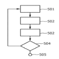
도 6은 피사체에 광을 조사하는 광 조사 방법의 실시예를 나타내는 순서도이다.The present invention and various aspects thereof will be apparent from and elucidated with reference to the embodiments described hereinafter.
Fig. 1 shows, by way of example, an embodiment of a light irradiation apparatus during a processing time period.
FIG. 2 shows a light irradiation apparatus as a schematic example during a sensing time interval.
Fig. 3 shows, as a schematic example, an array of VCSELs of the light irradiation apparatus.
Fig. 4 shows, as a schematic example, an outer case of a light irradiation device formed as a portable device.
Fig. 5 shows, as a schematic example, the arrangement of VCSELs of another embodiment of the light irradiation apparatus.
6 is a flowchart showing an embodiment of a light irradiation method for irradiating light to a subject.
도 1은 피사체에 광을 조사하는 광 조사 장치의 실시예를 개략적인 일례로서 나타낸다. 광 조사 장치(1)는 피사체(3)를 처리하기 위한 처리광(2)을 발생시키는 광원(4)을 포함한다. 본 실시예에 있어서, 피사체(3)는 사람의 피부이고, 처리광은 피부의 체모를 제거하는 데 사용된다. 광 조사 장치는 처리 시간 구간에서 처리광(2)을 그리고 감지 시간 구간에서 감지광(5)을 교대로 발생하도록 광원(4)을 제어하기 위한 제어부(9)를 더 포함한다. 도 1은 처리 시간 구간에서 광 조사 장치(1)를 나타내며, 즉, 도 1은 체모를 제거하기 위한 피부(3)에의 처리광(2)의 결합을 나타낸다.Fig. 1 schematically shows an embodiment of a light irradiation device for irradiating light to a subject. The light irradiating apparatus 1 includes a light source 4 that generates processed
도 2는 감지 시간 구간에서 광 조사 장치(1)를 개략적인 일례로서 나타낸다. 광원(4)는 감지 시간 구간에서 피사체(3)를 감지하기 위해 감지광(5)을 발생하도록 구성되며, 감지광(5)은 피사체(3)에 결합된다. 피부(3)에의 감지광(5)의 이러한 결합은 도 2에서 쇄선 화살표(7)로 나타내어 있다. 감지광은 피사체(3)를 진행하며, 이는 도 2에서 점선 화살표(5)에 의해 표시되어 있으며, 피사체(3)를 진행한 후에, 감지광(5)은 피사체(3)를 떠난다.Fig. 2 shows the light irradiation apparatus 1 as a schematic example in the detection time interval. The light source 4 is configured to generate the sensing light 5 to sense the
광 조사(1)는 피사체(3)를 떠난 감지광(5)을 검출하기 위한 광 검출기(8)를 더 포함한다.The light irradiation (1) further includes a photodetector (8) for detecting the detection light (5) leaving the object (3).
처리광(2) 및 감지광(5)이 교대로 발생되기 때문에, 처리광(2) 및 감지광(5)의 발생은 분리된다. 본 실시예에 있어서, 처리광(2)은 처리를 위해, 특히, 피부 조직에 악영향을 끼치는 것 없이, 대체로 피부(3)의 체모를 제거하는데 최적화되고, 감지광(5)은 감지를 위해 최적화된다. 특히, 처리광(2)은 스펙트럼 방출 및 전력 밀도를 가지며, 이는 더 적은 고통과 더 적은 부작용을 갖는 효율적인 제모를 하도록 주변의 피부에 더 적게, 모낭의 멜라닌에서 처리광(2)이 주로 흡수되도록 한다. 처리광(2)은 570-1200 nm의 범위의 파장 및 2-30 J/cm2의 범위의 에너지 밀도를 갖는다. 또한, 감지광(5)은 570-1200 nm의 범위의 파장을 갖는 것이 바람직하지만, 감지광(5)은 처리광(2)의 강도와 상이한 강도를 갖는 것이 바람직하다. 제어부(9)는 감지 시간 구간 동안 감지광(5)의 강도가 변경되도록 광원(4)을 제어하기 위해 구성될 수 있다.The generation of the
광 검출기(8)는 본 실시예에서 포토다이오드이다.The photodetector 8 is a photodiode in this embodiment.
제어부(9)는 광원(4)이 처리 시간 구간에서 처리광(2)을 그리고 감지 시간 구간에서 감지광(5)을 반복적이고 교대로 발생하도록 구성된다. 또한, 감지광(5)을 이용하여 피사체(3)를 감지하기 위해, 제어부(9)는 피사체(3)의 처리를 1회만 중단시키도록 구성될 수도 있으며, 감지 시간 구간이 제1 처리 시간 구간 및 제2 처리 시간 구간 사이에 시간적으로 위치된다.The control unit 9 is configured to cause the light source 4 to repeatedly and alternately generate the
본 실시예에 있어서, 광원(4)은 평면 배치에서 VCSEL들의 어레이를 포함한다. 광 검출기(8)는 VCSEL들의 어레이 옆에 배치된다. VCSEL들의 어레이는 더 상세하게 도 3에 개략적인 일례로서 도시되어 있다.In this embodiment, the light source 4 comprises an array of VCSELs in a planar arrangement. A photodetector 8 is disposed next to the array of VCSELs. The array of VCSELs is shown in greater detail in FIG. 3 as a schematic example.
도 3에서 알 수 있는 바와 같이, 광원(4)은 길이 방향(13)으로 길이 치수 및 폭 방향(14)으로 폭 치수를 갖는 직사각형 형상의 VCSEL들의 어레이(11)를 포함하며, 길이 치수는 폭 치수보다 더 크다. 이 직사각형 형상은 일차원 형상으로서 간주될 수 있다. 길이 치수는 수 센티미터의 범위인 것이 바람직하고, 폭 치수는 수 밀리미터의 범위인 것이 바람직하다. 본 실시예에 있어서, 길이 치수는 1 cm 초과 3 cm 미만이고, 폭 치수는 1 mm 초과 3 mm 미만이다. 광 검출기(8)는 길이 방향(13)으로 VCSEL들(12)의 어레이(11) 옆에 배치된다.As can be seen in Figure 3, the light source 4 comprises an array 11 of rectangular VCSELs having a length dimension in the
VCSEL들(12)의 어레이(11)는 서브 그룹들(111, 112, 113, 121, 122, 및 123)로 분리되며, 서로 다른 서브 그룹(111, 112, 113, 121, 122, 및 123)의 VCSEL들이 원하는 조명 프로파일을 발생하기 위해, 상이한 파장 및/또는 상이한 강도의 광을 방출하도록 서로 독립적으로 서브 그룹(111, 112, 113, 121, 122, 및 123)을 제어하도록 제어부(9)가 구성된다. 바람직하게는, 동일한 서브 그룹의 VCSEL(12)들은 동일한 파장 및/또는 동일한 강도를 갖는 광을 방출한다.The array 11 of VCSELs 12 is divided into
광 검출기(8)는 각각의 서브 그룹(111, 112, 113, 121, 122, 및 123)의 VCSEL들(12)의 평균 위치에 대해 서로 다른 거리를 갖는 위치에 위치된다. 제어부(9)는, 감지 시간 구간에서 서브 그룹들(111, 112, 113, 121, 122, 및 123) 중 오직 하나가 감지광(5)을 한 번에 방출하도록 광원(4)을 제어하도록 구성되는 것이 바람직하다. 이것은 광 검출기(8)에 의해 검출되고 서로 다른 서브 그룹에 의해 방출된 감지광을 쉽게 구별하도록 한다.The photodetector 8 is positioned at a different distance relative to the average position of the VCSELs 12 of each of the
도 1 및 도 2를 다시 참조하면, 광 조사 장치(1)는 피사체(3)로부터 주로 오는 광이 검출된 것을 보장하는 광 검출기(8) 주위에 개구(10)를 더 포함한다. 이러한 개구(10)는 깔대기 형상을 갖는다.1 and 2, the light irradiation apparatus 1 further includes an
광 조사 장치(1)는 피사체에 대해 광원의 이동 속도를 측정하기 위한 속도 측정부(15)를 더 포함하며, 제어부(9)는 측정된 속도에 따라 광원(4)을 제어하도록 구성된다. 특히, 광원(4)이 이 부분들에 걸쳐 피사체(3)를 기준으로 이동되는 경우, 제어부(9)는, 피사체(3)의 서로 다른 부분들이 처리광(2)에 의해 동일하게 조명받도록 측정된 속도에 따라 광원(4)을 제어하도록 구성된다. 이는 광 조사 장치(1)가 피사체(3)에 대해 비균일하게 이동되는 경우라도, 피사체(3)가 균일하게 처리되는 것을 보장한다.The light irradiating apparatus 1 further includes a
속도 측정부(15)는 광학 마우스 센서 및 타이머를 포함하는 것이 바람직하다. 광학 마우스 센서는 광원의 변위를 측정하고, 타이머는 시간을 측정한다. 이로부터, 광원의 속도가 시간에 의해 분할된 변위로서 계산된다. 광학 마우스 센서들은 발광 다이오드 또는 레이저 다이오드로부터 방출된 광을 갖는 표면을 조명하고, 표면으로부터 반사된 광을 검출한다. 예를 들어, 광학 마우스 센서들은 Avago 사, 필립스, 및 ST Microelectronics 사에서 이용할 수 있다.The
바람직하게는, 광 조사 장치(1)는 핸드헬드 장치로서 형성되는데, 이는 도 4에 개략적인 일례로서 도시되어 있다. 도 1 내지 도 3을 참조하여 전술한 소자들은, 바람직하게는, 손에 광 조사 장치(1)를 보유하는 데 사용되는 휴대부(17) 및 처리광(2)과 감지광(5)을 교대로 방출하는 광원(4)을 적어도 포함하는 광 방출부(18)를 포함하는 케이스(19) 내에 위치되는 것이 바람직하다. 핸드헬드 장치로서 형성되는 이러한 조사 장치(1)는 사람의 피부(3)의 상이한 부분들을 치료하기 위해 사람의 피부(3)에 대해 사람에 의해 보유되고 이동될 수 있다.Preferably, the light irradiation device 1 is formed as a handheld device, which is shown schematically as an example in Fig. The above-described elements with reference to Figs. 1 to 3 preferably include a carrying
도 3에서, VCSEL들(12)의 어레이(11)는 길이 방향(13)으로 3개의 라인의 VCSEL들(12)을 포함하는 것으로서 도시되어 있다. 그러나, 광 조사 장치는 VCSEL들의 라인들을 더 많이 또는 더 적게 포함할 수도 있다. 또한, 각 라인은 더 많거나 더 적은 VCSEL들을 포함할 수 있다. 도 5는 피사체에 광을 조사하기 위해 광 조사 장치의 도 1 내지 도 3을 참조하여 전술한 또 다른 소자들과 함께 사용될 수 있는 광원(304)을 개략적인 일례로서 도시하고 있다. 광원(304)은 5개의 서로 다른 서브 그룹을 정의하는 5개의 라인의 VCSEL들의 포함하는 VCSEL들(311)의 어레이를 포함한다. 또한, 이들 5개의 서브 그룹들은 제어부(9)에 의해 서로 개별적으로 처리될 수 있다. 특히, 서로 다른 서브 그룹들은 원하는 조명 프로파일을 제공하기 위해 동일한 및/또는 상이한 파장, 및/또는 동일한 및/또는 상이한 강도를 방출할 수 있다.In FIG. 3, the array 11 of VCSELs 12 is shown as including three lines of VCSELs 12 in the
층(320)은 VCSEL들이 탑재되는 서브마운트이다. 이러한 서브마운트들은, 예를 들어, 구리, 금, 은, 팔라듐, 은, 또는 기타 금속들 또는 금속성분들로 도금한, 예를 들어, 산화 알루미늄, 질화 알루미늄, 세라믹, 또는 산화 베릴륨으로 만들어진다. 대안으로서, VCSEL들은 구리 서브마운트 상에 바로 탑재될 수 있다. 층(321)은, 예를 들어, 알루미늄 또는 구리로 만들어진 히트 스프레더 및 히트 싱크로서의 역할을 한다.
도 1 내지 도 3을 다시 참조하면, 제어부(9)는 처리광(2)이 검출된 감지광(5)에 따라 발생되도록 광원(4)을 제어하도록 구성되며, 특히, 제어부는, 처리광이 검출된 감지광을 나타내는 광 검출기에 의해 발생된 신호의 진폭에 따라 발생되도록 광원을 제어하기 위해 구성된다. 검출된 감지광(5)은 피사체(3)의 특성을 나타낸다. 따라서, 처리광(2)이 검출된 감지광(5)에 따라 발생되도록 광원(4)을 제어함으로써, 피사체(3)의 처리가 피사체(3)의 특성에 따라 수행될 수 있다.1 to 3, the control unit 9 is configured to control the light source 4 so that the
본 실시예에 있어서, 제어부(9)는 처리광(2)이 피사체(3)의 판정된 특성에 따라 발생되도록 검출된 감지광(5)으로부터 피사체(3)의 특성을 판정하고 광원(4)을 제어하기 위해 구성된다. 따라서, 처리광(2)의 조사는 검출된 감지광(5)에 따라 바로 수행되거나, 또는 처리광(2)의 조사가 피사체의 특성에 따라 수행될 수 있으며, 이는 검출된 감지광(5)으로부터 판정된다.The controller 9 determines the characteristics of the subject 3 from the detected light 5 detected so that the processed
제어부(9)는 검출된 감지광(6)으로부터 감지광(5)의 흡수를 판정하고 처리광(2)이 판정된 흡수에 따라 발생되도록 광원(4)을 제어하도록 구성된다. 이는 피사체(3)의 흡수 특성들에 따라 처리광(2)을 제어하도록 한다.The control unit 9 is configured to determine the absorption of the sensing light 5 from the detected
제어부(9)는, 특히, 감지광(5)의 흡수에 기초하여 피사체(3)의 또 다른 특성을 판정하도록 또한 구성될 수 있다. 예를 들어, 피부 타입 및/또는 피부 색상 및/또는 태닝의 정도가 검출된 감지광(5)에 기초하여, 특히, 판정된 흡수에 기초하여 판정될 수 있다. 제어부(9)는 피사체(3)의 판정된 특성, 특히, 감지광(5)의 판정된 흡수와 처리광(2)의 특성들 사이에 할당을 정의하는 룩업 테이블 또는 함수를 포함하는 것이 바람직하다. 따라서, 피사체(3)의 특성이 판정된 후에, 제어부(9)에 저장된 처리광(2)의 특성들에 따라 처리광(2)이 발생될 수 있다. 피사체(3)의 판정된 특성들과 처리광(2)의 특성들 사이의 대응하는 할당은 교정 측정법에 의해 판정된다. 또한, 검출된 감지광(5)에 따라 피사체(3)의 특성을 판정하기 위해, 검출된 감지광(5)과 피사체(3)의 특성 사이의 할당을 나타내는 룩업 테이블 또는 함수가 사용될 수 있으며, 이 할당들은 교정 측정법에 의해 판정될 수도 있다. 예를 들어, 감지광(5)은 알려진 특성을 갖는 피사체(3)에 조사될 수 있으며, 검출된 감지광(5)은 대응하는 할당을 발생하기 위해 피사체(3)의 알려진 특성에 할당된다. 감지광의 흡수는 이하 방정식에 따라 판정되는 것이 바람직하다.The control unit 9 may also be configured to determine another characteristic of the subject 3 based on absorption of the sensing light 5 in particular. For example, the skin type and / or the degree of skin color and / or tanning can be determined based on the detected light 5, in particular based on the determined absorption. The control section 9 preferably includes a lookup table or function defining an assignment between the determined characteristics of the subject 3 and in particular between the determined absorption of the sensing light 5 and the characteristics of the

여기서, χg는 광원 및 광 검출기 사이의 거리를 나타내고, αg는 피사체의 흡수 계수를 나타내며, 피사체의 흡수 계수는 유효 흡수 계수로서 간주될 수 있다. 거리 χg 는, 광원에 의해 방출되는 강도 I0 및 광 검출기에 의해 검출되는 강도 Is 를 측정함으로써 흡수 계수 αg가 판정될 수 있도록 알려져 있다. 제어부(9)는 판정된 흡수 계수 αg 에 따라 처리광(2)의 발생을 제어하도록 구성될 수 있다. 광원이 상이한 위치에 배치된 발광 소자들의 어레이를 포함하는 경우, 이들 발광 소자들의 평균 위치는 광원과 광 검출기 사이의 거리를 판정하는 데 사용되고, 광 검출기가 상이한 위치에 배치된 수개의 광 감지 소자들을 포함하는 경우, 이들 광 감지 소자들의 평균 위치는 광원과 광 검출기 사이의 거리를 판정하는 데 사용된다.Here, χ g represents the distance between a light source and a light detector, α g denotes the absorption coefficient of the object, the absorption coefficient of the object can be thought of as the effective absorption coefficient. The distance χ g is known so that the absorption coefficient α g can be determined by measuring the intensity I 0 emitted by the light source and the intensity I s detected by the photodetector. The control unit 9 can be configured to control the generation of the
제어부(9)는, 감지 시간 구간에서는 제1 감지 광이 제1 서브 그룹으로부터 방출되고, 그 후 제2 감지 광이 제2 서브 그룹으로부터 방출되도록 광원(4)을 제어하도록 구성될 수 있으며, 제1 감지광 및 제2 감지광은 광 검출기(8)에 의해 검출되며, 제어부(9)는 검출된 제1 감지 신호 및 검출된 제2 감지 신호에 따라 광원(4)을 제어하도록 구성된다. 특히, 제어부(9)는 처리광(2)이 제1 감지광 및 제2 감지광에 따라 발생되도록 광원(4)를 제어하도록 구성된다.The control unit 9 may be configured to control the light source 4 such that the first sensing light is emitted from the first subgroup in the sensing time interval and then the second sensing light is emitted from the second subgroup, The first sensing light and the second sensing light are detected by the photodetector 8 and the controller 9 is configured to control the light source 4 according to the detected first sensing signal and the detected second sensing signal. In particular, the control unit 9 is configured to control the light source 4 such that the
제어부(9)는 처리광(2)이 제1 감지광 및 제2 감지광에 따라 발생되도록 광원(4)을 제어하도록 구성되는 것이 바람직하다. 제어부(9)는 광 검출기(8)에 의해 발생되는 신호의 진폭에 따라 광원(4)을 제어하도록 구성되는 것이 더 바람직하며, 즉, 제어부(9)는 검출된 제1 감지광을 나타내는 제1 신호의 제1 진폭 및 검출된 제2 감지광을 나타내는 제2 감지 신호의 제2 진폭에 따라 광원(4)을 제어하도록 구성되는 것이 더 바람직하다.The control unit 9 is preferably configured to control the light source 4 so that the
이들 진폭들은 피사체(3)의 광학 특성 및 피사체(3), 특히, 피부에의 처리광(2)의 침투 깊이를 나타낸다. 따라서, 처리광(2)이 검출된 제1 감지광 및 검출된 제2 감지광에 따라 발생되도록 제어부(9)를 구성함으로써, 처리광(2), 특히, 강도 및 파장이 피사체(3)로의 처리광(2)의 해당 침투 깊이에 부합하도록 될 수 있다.These amplitudes represent the optical characteristics of the subject 3 and the depth of penetration of the processed
피사체(3)가 인간이나 동물의 피부인 것이 더 바람직하며, 제어부(9)는 검출된 제1 감지광과 검출된 제2 감지광으로부터 피부의 표피에서의 제1 및 제2 감지광의 흡수 및 진피에서 제1 및 제2 감지광의 흡수를 판정하여 처리광(2)이 표피에서 판정된 흡수 및 진피에서 판정된 흡수 중 적어도 하나, 특히, 표피의 판정된 흡수 계수 및 진피의 판정된 흡수 계수 중 적어도 하나에 따라 발생되도록 광원(4)을 제어하도록 구성된다. 특히, 제어부(9)는 처리광(2)이 표피에서 판정된 흡수에 따라 발생되도록 광원(4)을 제어하도록 구성된다.It is more preferable that the
광원(4)에서 광 검출기(8)로 가는 도중에, 감지광은 첫 번째 표피를 통과하여, 그 다음 진피를 통과하고, 마지막에 두 번째 표피를 통과한다. 표피는 피부의 최상층으로서, 일반적으로 겨우 약 0.1 mm 두께이다. 표피는 광을 흡수하고 피부 색상 및 태닝의 정도를 판정하는 멜라닌을 함유한다. 표피에서 분산하는 광은 비교적 약하고 일반적으로 피부의 이 층의 적은 두께로 인해 무시될 수 있다. 표피 바로 아래는 일반적으로 수 밀리미터의 두께를 갖는 진피이다. 진피에 있어서, 광은 헤모글로빈과 물에 의해 흡수된다. 또한, 광은 피부의 표면과 평행하게 광을 확산시키는 진피에서 산란되어 광 검출기(8)에 도달한다. 광원(4)에서 광 검출기(8)로 분산하는 광은 방정식(1)에 따라 광원(4)으로부터 광 검출기(8)로의 강도의 지수 감쇄에 의해 대략 특성화될 수 있다.On the way from the light source 4 to the photodetector 8, the sensing light passes through the first epidermis, then through the dermis, and finally through the second epidermis. The epidermis is the top layer of the skin, generally only about 0.1 mm thick. The epidermis contains melanin that absorbs light and determines skin color and degree of tan. The light scattering from the epidermis is relatively weak and can generally be ignored due to the low thickness of this layer of skin. Just below the epidermis is the dermis, which usually has a thickness of a few millimeters. In the dermis, light is absorbed by hemoglobin and water. In addition, the light is scattered in the dermis that diffuses the light in parallel with the surface of the skin and reaches the photodetector 8. The light dispersed from the light source 4 to the photodetector 8 can be roughly characterized by an exponential decay of the intensity from the light source 4 to the photodetector 8 according to equation (1).
진피에서 제1 감지광에 의해 진행된 거리가 진피에서 제2 감지광에 의해 진행된 거리와 상이하다면, 검출된 제1 감지광을 나타내는 제1 신호의 제1 진폭 및 검출된 제2 감지광을 나타내는 제2 신호의 제2 진폭은 표피의 흡수 계수 αe와 진피의 흡수 계수αd를 판정할 수 있도록 하며, 표피에서 감지광에 의해 진행된 거리 χe는 약 0.1 mm로 알려진 표피 두께의 2배이고, 진피에서 감지광에 의해 진행된 거리χd는 광원(4)과 광 검출기(8) 사이의 거리에 의해 주어지는 것으로 가정한다. 광원(4)이 상이한 위치에 배치된 발광 소자들의 어레이(11)를 포함하는 경우, 거리 χd는 발광 소자들의 평균 위치 및 광 검출기(8)의 위치 사이의 거리로서 가정되는 것이 바람직하다. 광 검출기(8)가 상이한 위치에 배치되는 수개의 광 감지 소자들을 포함하는 경우, 이들 광 감지 소자들의 평균 위치는 광원(4)과 광 검출기(8) 사이의 거리를 판정하는 데 사용되는 것이 바람직하다. 피부 색상/타입 및 태닝의 정도는 표피의 흡수 특성, 즉, αe로부터 판정될 수 있다.If the distance traveled by the first sensing light in the dermis is different from the distance traveled by the second sensing light in the dermis, the first amplitude of the first signal representing the detected first sensing light and the second amplitude of the
흡수 계수(αe 및 αd)는 유효 흡수 계수로서 간주될 수 있다.The absorption coefficients (? E and? D ) can be regarded as effective absorption coefficients.
처리광(2)이 감지광의 흡수에 따라 발생되도록 광원(4)을 제어하기 위해, 제어부(9)는 감지광의 판정된 흡수에 대해 처리광(2)의 특성들을 할당하는 룩업 테이블 또는 함수를 포함하는 것이 바람직하다. 예를 들어, 처리광(2)의 강도 및/또는 파장은 제어부(9)에 의해 판정되는 흡수 계수에 할당될 수 있다. 처리광(2)의 특성들과 감지광의 흡수 사이의 할당들은 교정 측정법에 의해 미리 판정될 수 있다. 예를 들어, 인간 또는 동물의 피부에 있어서, 처리광(2)의 최적화된 특성이 알려진다면, 감지광의 흡수는 피부에 대해 판정될 수 있고, 판정된 흡수는 할당을 발생하기 위해 처리광(2)의 최적화된 특성에 할당될 수 있으며, 이는 제어부(9)에 저장될 수 있다.In order to control the light source 4 such that the
일 실시예에 있어서, VCSEL들의 어레이는 어레이 내에서보다 어레이의 단부에서 더 큰 VCSEL들의 공간 밀도를 포함한다. VCSEL들의 어레이가 2차원 어레이이면, 단부는 어레이의 엣지로 간주될 수 있는데, 즉, 이 경우에, VCSEL들의 공간 밀도는 어레이 내에서보다 어레이의 단부에서 더 큰 것이 바람직하다.In one embodiment, the array of VCSELs includes the spatial density of the larger VCSELs at the end of the array than in the array. If the array of VCSELs is a two-dimensional array, then the end can be regarded as the edge of the array, i.e., in this case, the spatial density of the VCSELs is preferably larger at the end of the array than in the array.
처리광(2)이 향하는 피사체(3)의 위치는 단일의 VCSEL(12)이 아닌 여러 개의 이웃하는 VCSEL들에 의해 영향을 받는다. VCSEL들의 어레이의 단부에서는, VCSEL들이 감소된 수의 이웃을 가지므로, 피사체(3)를 처리하는 데 사용되고 있는 처리광(2)의 강도가 VCSEL들의 어레이의 단부에서 감소되며, 이는 VCSEL들이 피사체(3)의 해당 위치에 영향을 덜 미치기 때문이다. VCSEL들의 어레이의 단부에서는, VCSEL들의 공간 밀도가 어레이 내에서보다 더 크다면, 이 더 큰 공간 밀도는 VCSEL들의 어레이의 단부에서 감소된 처리 효과를 상쇄시킬 수가 있다. 특히, VCSEL들의 어레이의 단부에 배치되는 피사체(3)의 위치가 VCSEL들의 어레이에 대해 보다 중심에 배치된 피사체(3)의 위치와 동일한 강도를 수신하도록, VCSEL들의 어레이의 단부에서 VCSEL들의 공간 밀도가 구성된다.The position of the
피사체에 광을 조사하는 광 조사 방법의 실시예는 도 6에 도시된 순서도를 참조하여 이하에 기재될 것이다.An embodiment of a light irradiation method for irradiating light to a subject will be described below with reference to the flowchart shown in Fig.
단계 501에서, 제어부(9)는 광원(4)이 감지 시간 구간의 감지광(5)을 발생하도록 광원(4)을 제어한다. 감지광은 피사체(3)에 결합된다.In
단계 502에서, 감지광이 피사체(3)를 진행하고 피사체(3)를 떠난 후, 감지광(5)은 광 검출기(8)에 의해 검출된다.At
단계 503에서, 제어부(9)는 광원(4)이 검출된 감지광에 따라 처리 시간 구간의 처리광(2)을 발생하도록 광원(4)을 제어한다. 처리광은 피사체를 치료하기 위해, 특히, 피부로부터 체모를 제거하기 위해 피사체(3)에 결합된다.In step 503, the control unit 9 controls the light source 4 so that the light source 4 generates the
단계 504에서, 광의 조사를 중단해야하는지 계속해야하는지의 여부가 결정된다. 예를 들어, 사용자가 광 조사 장치를 스위치 오프함으로써 광의 조사를 멈출 수 있다. 이 경우에, 광 조사 방법은 스텝 505에서 종료한다. 예를 들어, 광 조사 장치가 스위치 오프되지 않기 때문에 광 조사 방법이 계속 되어야 한다면, 광 조사 방법은 단계 501로 진행한다.In
감지 시간 구간은 처리 시간 구간보다 더 작은 것이 바람직하다. 특히, 감지 시간 구간이 수 100 마이크로세컨드의 지속 기간, 예를 들어, 10 밀리세컨드보다 더 적은, 더 바람직하게는, 1 밀리세컨드보다 적은 것을 갖는 반면에, 처리 시간 구간은 적어도 수 밀리세컨드, 예를 들어, 10 밀리세컨드보다 더 큰 지속 기간, 더 바람직하게 100 밀리세컨드보다 더 큰, 가장 바람직하게 1초보다 더 큰 것을 갖는다.The detection time interval is preferably smaller than the processing time interval. In particular, the detection time interval has a duration of several hundreds of microseconds, e.g., less than 10 milliseconds, more preferably less than 1 millisecond, while the processing time interval is at least a few milliseconds, e.g., For example, greater than 10 milliseconds, more preferably greater than 100 milliseconds, and most preferably greater than 1 second.
광 조사 장치는 광열 제모 및 피부 치료 분야에 사용되는 것이 바람직하며, VCSEL들의 어레이는 이상적인 파장 범위, 면 광원, 전력 절약, 및 신뢰성과 같은 다수의 이익을 제공한다. 또한, VCSEL들의 어레이는 광학 센서들을 일체화하는 기회를 제공하며, 이는 피부로부터 피드백을 가능하게 한다.The light irradiation device is preferably used in the field of phototherapy and skin treatment, and the array of VCSELs provides a number of benefits such as ideal wavelength range, surface light source, power saving, and reliability. In addition, the array of VCSELs provides an opportunity to integrate optical sensors, which enables feedback from the skin.
피부를 감지하기 위해 처리되는 특별한 전기적 어드레싱과 레이저 어레이와 조합하여 단일의 포토다이오드가 사용될 수 있다. 광 조사 장치 및 광 조사 방법은 피부에서 적외선의 흡수의 온라인 측정을 가능하게 하며, 이는 피부 타입 및 태닝의 정도에 안정적인 피드백을 부여한다. 이것은 충분한 자가적응 시스템을 허용한다. 따라서, 특성 판정부는 검출된 감지광에 따라 피부 타입 및/또는 태닝의 정도를 판정하도록 구성되는 것이 바람직하며, 제어부는 판정된 피부 타입 및/또는 판정된 태닝의 정도에 따라 처리광의 발생을 제어하도록 구성된다.A single photodiode can be used in combination with the laser array and special electrical addressing that is processed to detect the skin. The light irradiation apparatus and the light irradiation method enable on-line measurement of the absorption of infrared light in the skin, which gives stable feedback on the type of skin and the degree of tanning. This allows a sufficient self-adaptive system. Therefore, it is preferable that the characteristic judging section is configured to judge the type of skin and / or the degree of tanning in accordance with the detected sensed light, and the control section controls the generation of the processing light according to the judged skin type and / .
감지광은 상이한 파장을 갖는 광을 방출할 수 있다. 이것은 피부에의 파장 의존적 방사의 침투를 측정할 수 있도록 한다. 이 파장 의존적 방사의 침투는 처리광의 개별 파장이 원하는 침투 프로파일을 최적화하는 레벨로 감쇠되도록 처리광을 발생하는데 사용될 수 있다.The sensing light may emit light having a different wavelength. This allows the measurement of the penetration of wavelength-dependent radiation into the skin. The penetration of this wavelength dependent radiation can be used to generate the processing light so that the individual wavelengths of the processing light are attenuated to a level that optimizes the desired infiltration profile.
VCSEL들을 사용하는 대신에, 다른 종류의 발광 소자들이 섬광 전구 및 레이저처럼 사용될 수 있다. 본 실시예에 있어서, 처리광은 570-1200 nm 범위의 파장, 2-30 J/cm2 범위의 에너지 밀도, 및 1-600 ms 내의 펄스 지속 시간을 갖는다.Instead of using VCSELs, other types of light emitting devices can be used like flash bulbs and lasers. In this embodiment, the processing light has a wavelength in the range of 570-1200 nm, an energy density in the range of 2-30 J / cm 2 , and a pulse duration in the range of 1-600 ms.
광 조사 장치는 피부 화상 및 통증과 같은 원하지 않은 부작용을 최소화하는 반면, 특정 온도 위로 모낭을 가열하도록 구성되는 것이 바람직하다. 처리광의 이상적인 파장과 최적 조건의 양은 피부 타입과 태닝의 정도 등과 같은 개별 파라미터에 의존하고, 따라서 개별적인 설정을 필요로 한다. 이들 설정은 제어부(9)에 의해 검출된 감지광에 따라 판정된다.The light irradiation device is preferably configured to heat the hair follicle to a specific temperature while minimizing unwanted side effects such as skin burns and pain. The ideal wavelength of the processing light and the amount of optimal conditions depend on individual parameters such as the type of skin and the degree of tanning, and thus require individual settings. These settings are determined according to the detection light detected by the control unit 9. [
피사체에 광을 조사하기 위하여, 광원은 VCSEL들의 어레이와 같은 레이저들을 포함하는 것이 바람직하며, 이는 레이저는 좁은 스펙트럼 방출을 제공하고, 정확하게 전력 밀도를 제어할 수 있도록 하며, 더 적은 고통과 부작용으로 효율적인 제모를 수행하기 위해, 주위 피부의 흡수에 대해 모낭의 멜라닌에서 최대한의 흡수에 맞도록 하기 때문이다.In order to illuminate the subject, the light source preferably includes lasers, such as an array of VCSELs, which allow for narrow spectrum emission, precisely control the power density, and are effective for less pain and side effects In order to perform hair removal, the absorption of the surrounding skin is adjusted to the maximum absorption in the melanin of the hair follicle.
VCSEL들의 어레이는 수 10 W에 달하고, 여러 추가적인 이점을 제공하는 요구되는 레이저 전력을 제공하기에 비용 대비 효과적인 방식을 시현한다. 다수의 VCSEL들의 평면 배치는 폼 팩터(form factor)를 구성하도록 한다. 단일의 VCSEL은 약 100 mW의 전력을 갖는 것이 바람직하다. 따라서, VCSEL들의 어레이는 수 100개의 VCSEL들을 포함하는 것이 바람직하다. 도 4에 도시된 장치와 같이 지속적으로 움직이는 핸드헬드 장치를 갖는 제모 절차에서, 선을 따라, 특히, 다수의 선을 따라 VCSEL들을 배치하는 것이 유익할 수 있다. 또한, 다수의 VCSEL들의 이러한 평면 배치는 히트싱크를 간소화한다.The array of VCSELs reaches several tens of watts and presents a cost effective way to provide the required laser power to provide several additional benefits. The planar layout of multiple VCSELs allows for a form factor to be configured. The single VCSEL preferably has a power of about 100 mW. Thus, the array of VCSELs preferably comprises hundreds of VCSELs. In a depilation procedure with a continuously moving handheld device, such as the device shown in Fig. 4, it may be beneficial to arrange the VCSELs along the lines, especially along a plurality of lines. This planar arrangement of multiple VCSELs also simplifies the heat sink.
약간 발산하는 원뿔 내의 VCSEL들의 방출 특성은, 피부에 대하여 수 밀리미터의 거리에서 간단하게 렌즈 또는 반사기와 같은 추가적인 광학 구성 없이 이들을 사용할 수 있도록 한다. 이는 비용 대비 효과적인 평탄한 시스템을 가져온다. 또한, VCSEL들은 높은 전력 변환 효율과 낮은 비용으로 600-1100 nm의 파장 범위에서 생성될 수 있다.The emission characteristics of the VCSELs in the slightly diverging cones allow them to be used without additional optical configuration, such as a lens or reflector, at a distance of a few millimeters to the skin. This results in a cost-effective flat system. In addition, VCSELs can be generated in the wavelength range of 600-1100 nm with high power conversion efficiency and low cost.
바람직하게는 VCSEL들의 평면 배치인 VCSEL들의 어레이는, 길이 방향인 하나의 장축 및 폭 방향인 하나의 단축을 포함하는 것이 바람직하다. 피부의 지속적인 치료를 위해, 핸드헬드 장치는 단축을 따라서 이동되는 것이 바람직하다.Preferably, the array of VCSELs, which are planar arrangements of VCSELs, preferably comprise one major axis in the longitudinal direction and one minor axis in the transverse direction. For continuous treatment of the skin, the hand held device is preferably moved along the short axis.
VCSEL들은 제어부에 대해 개별 서브그룹에 전기적으로 연결되는 것이 바람직하며, 이는 전기 구동기로서 간주될 수도 있다. 예를 들어, 서브그룹들은 동일한 파장을 갖는 VCSEL들 및/또는 특정한 기하학적인 위치 주위에, 예를 들어, 어레이의 일측 또는 반대 측의 VCSEL들로 구성된다.The VCSELs are preferably electrically connected to separate subgroups for the control unit, which may be considered as an electric driver. For example, the subgroups may consist of VCSELs having the same wavelength and / or VCSELs on one side or the other side of the array, for example, around a particular geometric position.
광 검출기는 포토다이오드와 같은 전기 광학 센서인 것이 바람직하며, 이는 개별 서브그룹 내의 VCSEL들에 대하여 평균 거리가 상이한 위치에 배치된다. 하나의 서브그룹의 감지광은 피부를 침투하여, 모든 방향으로 산란되며, 피부를 통해, 예를 들어, 광 검출기 쪽으로 진행되고, 피부를 탈출하여 광 검출기에 부딪힌다. 서로 다른 서브그룹들로부터의 감지광은 광 검출기 쪽으로 피부내에서 상이한 거리로 진행해야만 한다. 따라서, 신호 강도는 피부의 광학 특성, 특히, 흡수 및 산란에 대한 정보를 포함한다.The photodetector is preferably an electro-optic sensor such as a photodiode, which is disposed at a position where the average distance is different for the VCSELs in the respective subgroup. The sense light of one subgroup penetrates the skin, is scattered in all directions, travels through the skin, for example to the photodetector, escapes the skin and strikes the photodetector. Detection light from different subgroups must travel to different distances within the skin towards the photodetector. Thus, the signal intensity includes information about the optical properties of the skin, in particular absorption and scattering.
광 검출기는, 바람직하게는, 그 옆의 윤곽이 뚜렷한 피부 영역으로부터만 감지광을 수광한다. 이는 광 검출기에 의해 검출되는 감지광이 실제로 피부를 진행하도록 보장한다. 이는 광 검출기(8) 주위의 개구(10)에 의해 실현되며, 바람직하게는 깔대기 형상을 가지며, 또한 감지 시간 구간 동안 적어도 피부와 접촉하는 것이 바람직하다.The photodetector desirably receives the detection light only from a skin area with a contoured side edge. This ensures that the sensing light detected by the photodetector actually travels through the skin. It is realized by the
바람직하게는, 감지 시간 구간 동안, 단 하나의 서브그룹이 한 번에 동작된다. 이는 광 검출기에 의해 수광되는 감지광이 어느 서브그룹으로부터 방출되는지를 알 수 있도록 한다. 광 검출기에 의해 발생되는 그 결과의 신호들은 측정시에 동작된 각각의 서브그룹과 상관하여 기록될 수 있다. 그 결과는 제어부에 저장되고, 처리 파라미터들은 이들 측정들과 관련하여 선택된다, 즉, 제어는 처리광의 설정이 검출된 감지광에 따라 저장되는 룩업 테이블을 포함하는 것이 바람직하다. 이것은 광 검출기가 각각의 감지광을 검출하는 경우, 검출된 감지광과 피사체를 처리하는 데 사용되어야 하는 처리광의 설정 사이에 할당이 저장되는 것을 의미한다. 이들 할당들은 피사체의 처리가 광 검출기에 의해 검출된 감지광에 따라 최적화되도록, 예를 들어, 교정 측정법에 의해 판정될 수 있다.Preferably, during the sensing time interval, only one subgroup is operated at a time. This makes it possible to know from which subgroup the detection light received by the photodetector is emitted. The resulting signals generated by the photodetector can be recorded in correlation with each subgroup operated at the time of measurement. The results are stored in the control unit, and the processing parameters are selected in relation to these measurements, i. E. The control preferably comprises a look-up table in which the setting of the processing light is stored according to the detected light detected. This means that, when the photodetector detects each detection light, the assignment is stored between the detected detection light and the setting of the processing light that should be used to process the object. These assignments may be determined, for example, by calibration measurements so that the processing of the subject is optimized according to the sensing light detected by the photodetector.
도 3에 도시된 VCSEL들(12)의 어레이(11)는 6개의 서브그룹들(111, 112, 113, 121, 122, 및 123)을 포함한다. 그러나, 제어부(9)는 유사하게 제어되는 이러한 몇몇 서브그룹들이 단일의 서브그룹으로서 간주되도록 구성될 수도 있다. 예를 들어, 도 3에 도시된 어레이(11)가 서브그룹들(111, 112, 및 113)로 구성되는 제1 서브그룹 및 서브그룹들(121, 122, 및 123)로 구성되는 제2 서브그룹의 2개의 서브그룹들을 포함하는 것으로서 간주될 수 있도록, 3개의 서브그룹들(111, 112, 및 113)이 유사하게 제어되고, 3개의 서브그룹들(121, 122, 및 123)이 유사하게 제어될 수 있다. 예를 들어, 감지 시간 구간 내의 제1 시간 구간 동안 제1 서브그룹이 감지광을 방출하고, 감지광이 피부를 진행하여, 광 검출기에 의해 마침내 검출되도록 제어될 수 있으며, 동일한 감지 시간 구간 내의 제2 시간 구간 동안, 제2 서브그룹이 피사체에 감지광을 방출하고, 감지광은 피사체를 통해 진행하여, 마침내 광 검출기에 의해 검출되도록 제어될 수 있다. 따라서, 이와 같이, 제1 감지광이 제1 감지 시간 구간 동안 검출되고, 제2 감지광이 제2 시간 구간 동안 검출된다.The array 11 of VCSELs 12 shown in FIG. 3 includes six
서로 다른 서브 그룹들은 상이하게 처리될 수 있도록 서로 다른 서브그룹들이 제어부(9)에 연결되는 것이 바람직하므로, 서로 다른 서브 그룹들은 상이한 파장을 갖는 감지광 및/또는 처리광을 방출할 수 있다. 바람직하게는, 전력 레벨, 즉, 처리광 및/또는 감지광의 강도는 각각의 파장의 흡수 특성에 따라 선택되며, 이는 각각의 피부 타입의 흡수 특성에 의존한다. 그러나, 특정의 원하는 조사 프로파일을 획득하기 위해 동일한 파장에서 동작할지라도, 서로 다른 서브그룹들의 VCSEL들이 상이한 전력 레벨로 설정될 수도 있다. 예를 들어, 서브그룹들(121, 123)이 동일한 파장에서 동작하더라도, 서브그룹(122)과 상이한 전력 레벨로 설정될 수 있다. 이것은, 측면에 대한 열 소실이 VCSEL들의 어레이의 중심에서보다 더 강하기 때문에 특히 유리하다.Since different subgroups are preferably connected to the control unit 9 so that different subgroups can be processed differently, different subgroups can emit the sensing light and / or the processing light with different wavelengths. Preferably, the power level, i.e., the intensity of the processed light and / or the detected light, is selected according to the absorption characteristics of the respective wavelengths, which depend on the absorption characteristics of each skin type. However, VCSELs in different subgroups may be set to different power levels, although they operate at the same wavelength to obtain a particular desired illumination profile. For example, even if
이동 방향이, 예를 들어, 속도 측정부(15)에 의해 수행된 속도 측정으로부터 알려진다면, 도 3에 도시된 3개의 라인들은 광원(4)이 피부의 한 지점을 통해 이동하는 동안에 시간에 대한 양호한 온도 램프를 획득하도록 서로 다른 전력 레벨에서 동작될 수 있다.If the direction of movement is known from the velocity measurement performed by, for example, the
검출된 감지광, 특히, 검출된 감지광에 따라 판정된 피사체의 특성은 처리광의 이하 설정들: 강도; 파장; 처리광이 반복적이고 간헐적으로 피사체에 조사되는 경우의 반복 빈도; 처리광이 펄스 방식으로 조사되는 경우의 펄스 지속 시간 중 적어도 하나를 판정하는 데 사용될 수 있다: The characteristics of the detected light, in particular the subject determined according to the detected light, are determined by the following settings: intensity; wavelength; A repetition frequency in the case where the processing light is repeatedly and intermittently irradiated to the object; Can be used to determine at least one of the pulse durations when the process light is irradiated in a pulsed manner:
전술한 실시예에서는 광원이 VCSEL들을 포함하는 것이 바람직하지만, 다른 실시예에서는 광원이 다른 발광 소자들을 포함할 수 있다. 예를 들어, 광원은 발광 다이오드, 유기 다이오드 및/또는 레이저 다이오드와 같은 고체 광원을 포함할 수 있다. 바람직한 레이저 다이오드는 VCSEL이다. 그러나, 엣지형-방출 레이저 다이오드 역시 광원의 발광 소자로서 사용될 수 있다.In the above-described embodiment, it is preferable that the light source includes VCSELs, but in other embodiments, the light source may include other light emitting elements. For example, the light source may include a solid light source such as a light emitting diode, an organic diode, and / or a laser diode. A preferred laser diode is a VCSEL. However, an edge-emitting laser diode can also be used as a light emitting element of a light source.
전술한 광 조사 장치 및 광 조사 방법은 사람의 피부의 체모를 제거하도록 구성되는 것이 바람직하지만, 광 조사 장치는 또 다른 종류의 피사체, 예를 들어, 기계 장치의 표면의 처리를 수행하는 데 사용될 수도 있다.Although it is preferable that the light irradiation apparatus and the light irradiation method described above are configured so as to remove human hair hair, the light irradiation apparatus may be used to perform processing of another kind of object, for example, a surface of a mechanical device have.
개시된 실시예에 대한 다른 변형예들은 도면, 발명의 개시, 및 첨부된 청구항을 숙독하여, 청구된 발명을 실시함으로써 당업자에 의해 이해되어 성취될 수 있다.Other variations on the disclosed embodiments can be accomplished by those skilled in the art by reading the drawings, the disclosure of the invention, and the appended claims, thereby implementing the claimed invention.
청구항에 있어서, "포함한다(comprising)"라는 용어는 다른 구성 요소나 단계를 배제하는 것이 아니며, "a" 또는 "an"의 부정관사는 복수를 배제하는 것이 아니다.In the claims, the term " comprising "does not exclude other elements or steps, and the indefinite article" a "or" an "does not exclude a plurality.
단일의 구성 단위 또는 장치는 청구항에서 인용되는 여러 항목의 기능을 실행할 수 있다. 어떤 방법들이 서로 상이한 종속항에 인용된다는 것은, 이러한 방법의 조합이 유리하게 이용될 수 없다는 것을 나타내는 것은 아니다.A single unit or device may perform the functions of the various items recited in the claims. The citation of certain methods in different dependent claims does not indicate that a combination of these methods can not be used to advantage.
검출된 감지광 또는 피사체의 판정된 특성에 의한 처리광의 설정의 판정 또는 하나 또는 여러 개의 구성 단위들 또는 장치들에 의해 수행되는 피사체의 특성의 판정과 같은 판정은 임의의 다른 수의 구성 단위들 또는 장치들에 의해 수행될 수 있다. 광 조사 방법에 따른 광 조사 장치의 판정 및/또는 제어는 컴퓨터 프로그램 및/또는 전용 하드웨어의 프로그램 코드 수단으로서 구현될 수 있다.The determination, such as the determination of the setting of the processing light by the detected light or the determined characteristic of the object, or the determination of the characteristics of the object performed by one or several constituent units or devices, may be performed using any other number of constituent units Lt; / RTI > devices. The determination and / or control of the light irradiation apparatus according to the light irradiation method can be implemented as a program code means of a computer program and / or a dedicated hardware.
컴퓨터 프로그램은 함께 또는 다른 하드웨어의 일부분으로서 광학 기록 매체 또는 고체 매체와 같은 적절한 매체 상에 저장/분배될 수 있지만, 인터넷 또는 기타 유선 또는 무선 통신 시스템을 통해서 다른 형식으로 분산되어 있을 수도 있다.The computer programs may be stored / distributed on suitable media, such as optical recording media or solid media, together or as part of different hardware, but may also be distributed in other formats via the Internet or other wired or wireless communication systems.
청구항의 임의의 참조 기호는 이들 청구항의 범주를 제한하는 것으로 해석되어서는 아니된다.Any reference signs in the claims shall not be construed as limiting the scope of these claims.
Claims (14)
상기 피사체는 인간 또는 동물의 피부이며,
상기 광 조사 장치(1)는,
피사체(3)를 처리하는 처리광(2) 및 피사체(3)를 감지하는 감지광(5)을 발생시키기 위한 광원(4),
상기 피사체(3)를 떠난 후의 상기 감지광(5)을 검출하기 위한 광 검출기(8), 및
상기 광원(4)이 처리 시간 구간에서는 처리광(2)을, 그리고 감지 시간 구간에서는 감지광(5)을 교대로 발생시키도록 상기 광원(4)을 제어하기 위한 제어부(9)
를 포함하며,
상기 광원(4)은 상기 처리광(2)과 상기 감지광(5)을 상기 피사체(3)에 결합시키도록 구성되며, 상기 광원(4)은 발광 소자들(12)의 어레이(11)를 포함하며, 상기 광원은, 처리광이 향하는 피사체의 위치가 수개의 이웃하는 발광 소자들에 의해 영향을 받도록 배치되며,
상기 제어부는, 상기 검출된 감지광으로부터 상기 피부에서의 상기 감지광의 흡수를 판정하고, 상기 처리광이 상기 판정된 흡수에 따라 발생되도록 상기 광원을 제어하도록 구성되는, 광 조사 장치.1. A light application apparatus for irradiating an object with light to remove hairs,
The subject is a human or animal skin,
The light irradiation device (1)
A light source 4 for generating the processing light 2 for processing the object 3 and the sensing light 5 for sensing the object 3,
A photodetector (8) for detecting the detection light (5) after leaving the subject (3), and
A control unit 9 for controlling the light source 4 so that the light source 4 alternately generates the processing light 2 in the processing time interval and the sensing light 5 in the sensing time interval,
/ RTI >
The light source 4 is configured to couple the processing light 2 and the sensing light 5 to the subject 3 and the light source 4 is connected to the array 11 of light emitting elements 12 Wherein the light source is arranged so that the position of the subject to which the processing light is directed is influenced by several neighboring light emitting elements,
Wherein the control unit is configured to determine the absorption of the sensing light in the skin from the detected sensing light and to control the light source such that the processing light is generated in accordance with the determined absorption.
상기 광원(4)은 수직 공진 표면 발광 레이저(vertical-cavity surface-emitting laser; VCSEL)를 포함하는 광 조사 장치.The method according to claim 1,
The light source (4) comprises a vertical-cavity surface-emitting laser (VCSEL).
상기 광원(4)은 발광 소자들의 어레이를 포함하며, 상기 발광 소자들의 공간 밀도는 상기 어레이 내에서보다 상기 어레이의 단부에서 더 큰 광 조사 장치.The method according to claim 1,
Wherein the light source (4) comprises an array of light emitting elements, wherein the spatial density of the light emitting elements is greater at the end of the array than in the array.
상기 광원(4)은 길이 방향(13)의 길이 치수 및 폭 방향(14)의 폭 치수를 갖는 직사각형 형상의 발광 소자들(12)의 어레이(11)를 포함하며, 상기 길이 치수는 상기 폭 치수보다 더 큰 광 조사 장치.The method according to claim 1,
The light source (4) comprises an array (11) of rectangular light emitting elements (12) having a length dimension in the longitudinal direction (13) and a width dimension in the width direction (14) A larger illuminating device.
상기 광 검출기(8)는 상기 길이 방향(13)으로 상기 발광 소자들(12)의 상기 어레이(11) 옆에 배치되는 광 조사 장치.5. The method of claim 4,
Wherein the photodetector (8) is arranged next to the array (11) of the light emitting elements (12) in the longitudinal direction (13).
상기 발광 소자들(12)은 서브 그룹들(111, 112, 113, 121, 122, 123)로 분리되며, 상기 제어부(9)는 한 번에 1개의 서브 그룹만이 상기 감지 시간 구간에서 감지광을 방출하도록 상기 광원(4)을 제어하도록 구성되는 광 조사 장치.The method according to claim 1,
The light emitting devices 12 are divided into subgroups 111, 112, 113, 121, 122 and 123, and the controller 9 controls the sub- To control the light source (4) to emit light.
상기 광 조사 장치(1)는 상기 피사체(3)로부터 들어오는 광이 검출되도록 보장하기 위해 상기 광 검출기 주위에 개구(10)를 더 포함하는 광 조사 장치.The method according to claim 1,
The light irradiation apparatus (1) further comprises an aperture (10) around the photodetector to ensure that light coming from the subject (3) is detected.
상기 제어부(9)는 상기 검출된 감지광(5)으로부터 감지광의 흡수를 판정하고, 상기 처리광(2)이 상기 판정된 흡수에 따라 발생되도록 상기 광원(4)을 제어하도록 구성되는 광 조사 장치.The method according to claim 1,
The control unit 9 controls the light source 4 so as to determine the absorption of the detection light from the detected detection light 5 and to cause the processing light 2 to be generated in accordance with the determined absorption. .
상기 광원(4)은, 적어도 제1 서브 그룹 및 제2 서브 그룹을 포함하는 서브 그룹(111, 112, 113, 121, 122, 123)으로 분리되는 발광 소자(12)들의 어레이(11)를 포함하며, 상기 제어부(9)는 상기 감지 시간 구간에서 제1 감지광이 제1 서브그룹으로부터 방출되고, 그 후 제2 감지광이 제2 서브그룹으로부터 방출되도록 상기 광원(4)을 제어하도록 구성되며, 상기 제1 감지광 및 상기 제2 감지광은 상기 광 검출기(8)에 의해 검출되며, 상기 제어부(9)는 검출된 상기 제1 감지광과 검출된 상기 제2 감지광에 따라 상기 광원(4)을 제어하도록 구성되는 광 조사 장치.9. The method of claim 8,
The light source 4 includes an array 11 of light emitting elements 12 separated into subgroups 111, 112, 113, 121, 122, 123 including at least a first subgroup and a second subgroup , And the controller (9) is configured to control the light source (4) such that the first sensing light is emitted from the first subgroup in the sensing time interval, and then the second sensing light is emitted from the second subgroup , The first sensing light and the second sensing light are detected by the photodetector (8), and the controller (9) detects the first sensing light and the second sensing light based on the detected first light and the second sensing light, 4). ≪ / RTI >
상기 제어부(9)는, 검출된 상기 제1 감지광 및 검출된 상기 제2 감지광으로부터 상기 피부의 표피 내의 상기 제1 감지광 및 제2 감지광의 흡수와, 상기 피부의 진피 내의 상기 제1 감지광 및 제2 감지광의 흡수를 판정하고, 상기 처리광(2)이 상기 표피 내의 판정된 흡수와 상기 진피 내의 판정된 흡수 중 적어도 하나에 따라 발생되도록 상기 광원(4)을 제어하도록 구성되는 광 조사 장치.10. The method of claim 9,
The controller 9 detects absorption of the first sensing light and the second sensing light in the skin of the skin from the detected first sensing light and the detected second sensing light, (4) so as to control the light source (4) so as to determine the absorption of the light and the second sensing light and to produce the processing light (2) according to at least one of the determined absorption in the skin and the determined absorption in the dermis Device.
상기 매체는 광학 기록 매체 또는 고체 매체이며,
상기 피사체는 인간 또는 동물의 피부이며,
상기 컴퓨터 프로그램은 제1항에 따른 광 조사 장치를 제어하는 컴퓨터에서 실행되는 경우, 상기 광 조사 장치로 하여금
광원(4)에 의해 피사체(3)를 처리하는 처리광(2) 및 피사체(3)를 감지하는 감지광(5)을 발생시키고, 상기 처리광(2)과 상기 감지광(5)을 상기 피사체(3)에 결합시키는 단계,
광 검출기(8)에 의해 상기 피사체(3)를 떠난 후의 상기 감지광(5)을 검출하는 단계, 및
상기 광원(4)이 처리 시간 구간에서는 처리광(2)을, 그리고 감지 시간 구간에서는 감지광(5)을 교대로 발생시키도록 제어부에 의해 상기 광원(4)을 제어하는 단계
를 수행시키기 위한 프로그램 코드들을 포함하며,
상기 광원(4)은 발광 소자들(12)의 어레이(11)를 포함하여, 상기 처리광이 향하는 피사체의 위치가 수개의 이웃하는 발광 소자들에 의해 영향을 받도록 하며,
상기 제어부는, 상기 검출된 감지광으로부터 상기 피부에서의 상기 감지광의 흡수를 판정하고, 상기 처리광이 상기 판정된 흡수에 따라 발생되도록 상기 광원을 제어하도록 구성되는, 매체.1. A medium for storing a computer program for irradiating a subject with light to remove hairs,
The medium is an optical recording medium or a solid medium,
The subject is a human or animal skin,
Wherein when the computer program is executed in a computer for controlling the light irradiation apparatus according to claim 1,
The processing light 2 for processing the object 3 and the detection light 5 for detecting the object 3 are generated by the light source 4 and the processing light 2 and the detection light 5 are emitted To the subject (3)
Detecting the detection light (5) after leaving the subject (3) by the photodetector (8), and
Controlling the light source 4 by the control unit such that the light source 4 alternately generates the processing light 2 in the processing time interval and the sensing light 5 in the sensing time interval
And a program code for causing the computer to perform the steps of:
The light source 4 includes an array 11 of light emitting elements 12 such that the position of the object to which the processed light is directed is influenced by several neighboring light emitting elements,
Wherein the control unit is configured to determine absorption of the sensing light in the skin from the detected sensing light and to control the light source such that the processed light is generated in accordance with the determined absorption.
Applications Claiming Priority (3)
| Application Number | Priority Date | Filing Date | Title |
|---|---|---|---|
| EP09165868.2 | 2009-07-20 | ||
| EP09165868 | 2009-07-20 | ||
| PCT/IB2010/053122 WO2011010239A1 (en) | 2009-07-20 | 2010-07-08 | Light application apparatus for applying light to an object |
Publications (2)
| Publication Number | Publication Date |
|---|---|
| KR20120049274A KR20120049274A (en) | 2012-05-16 |
| KR101727095B1 true KR101727095B1 (en) | 2017-05-02 |
Family
ID=42670308
Family Applications (1)
| Application Number | Title | Priority Date | Filing Date |
|---|---|---|---|
| KR1020127004191A KR101727095B1 (en) | 2009-07-20 | 2010-07-08 | Light application apparatus for applying light to an object |
Country Status (6)
| Country | Link |
|---|---|
| US (2) | US9375281B2 (en) |
| EP (1) | EP2456382B1 (en) |
| JP (1) | JP5715128B2 (en) |
| KR (1) | KR101727095B1 (en) |
| CN (1) | CN102470012B (en) |
| WO (1) | WO2011010239A1 (en) |
Families Citing this family (34)
| Publication number | Priority date | Publication date | Assignee | Title |
|---|---|---|---|---|
| US8048089B2 (en) | 2005-12-30 | 2011-11-01 | Edge Systems Corporation | Apparatus and methods for treating the skin |
| WO2014151104A1 (en) | 2013-03-15 | 2014-09-25 | Edge Systems Llc | Devices, systems and methods for treating the skin |
| EP2240099B1 (en) | 2008-01-04 | 2018-02-21 | Edge Systems LLC | Apparatus for treating the skin |
| WO2012020361A1 (en) * | 2010-08-11 | 2012-02-16 | Koninklijke Philips Electronics N.V. | Phototherapy method and device |
| WO2012023086A1 (en) * | 2010-08-17 | 2012-02-23 | Koninklijke Philips Electronics N.V. | Flexible light therapy device, a plaster and a bandage |
| EP2670334A1 (en) * | 2011-02-03 | 2013-12-11 | Tria Beauty, Inc. | Radiation-based dermatological devices and methods |
| US9789332B2 (en) | 2011-02-03 | 2017-10-17 | Tria Beauty, Inc. | Devices and methods for radiation-based dermatological treatments |
| US8679102B2 (en) | 2011-02-03 | 2014-03-25 | Tria Beauty, Inc. | Devices and methods for radiation-based dermatological treatments |
| US11406448B2 (en) | 2011-02-03 | 2022-08-09 | Channel Investments, Llc | Devices and methods for radiation-based dermatological treatments |
| US8685008B2 (en) | 2011-02-03 | 2014-04-01 | Tria Beauty, Inc. | Devices and methods for radiation-based dermatological treatments |
| US9308390B2 (en) | 2011-02-03 | 2016-04-12 | Tria Beauty, Inc. | Devices and methods for radiation-based dermatological treatments |
| US9173708B2 (en) * | 2011-03-30 | 2015-11-03 | Tria Beauty, Inc. | Dermatological treatment device with one or more laser diode bar |
| KR101964387B1 (en) * | 2012-03-21 | 2019-04-01 | 트리아 뷰티, 인코포레이티드 | Dermatological treatment device with one or more vertical cavity surface emitting laser(vcsel) |
| US20140135804A1 (en) | 2012-11-15 | 2014-05-15 | Ethicon Endo-Surgery, Inc. | Ultrasonic and electrosurgical devices |
| EP3065918B2 (en) | 2013-11-06 | 2021-09-29 | Koninklijke Philips N.V. | A system and a method for treating a part of a body |
| GB2583683B (en) * | 2013-12-04 | 2021-03-31 | Ipulse Ltd | Skin treatment apparatus utilising intense pulsed light (IPL) |
| EP4324414A3 (en) | 2014-12-23 | 2024-05-01 | HydraFacial LLC | Devices and methods for treating the skin using a rollerball or a wicking member |
| EP3202351B1 (en) * | 2016-02-02 | 2021-08-25 | Braun GmbH | Skin treatment device |
| EP3202359B1 (en) * | 2016-02-02 | 2021-08-25 | Braun GmbH | Skin treatment device |
| WO2017136891A1 (en) * | 2016-02-10 | 2017-08-17 | Helium 3 Resources Pty Ltd | A therapeutic method and device therefor |
| CN109310875A (en) * | 2016-06-15 | 2019-02-05 | 香港康美有限公司 | Go the device and method of hair removal |
| JP2019535427A (en) | 2016-11-22 | 2019-12-12 | ドミニオン エスセティック テクノロジーズ インコーポレイテッドDominion Aesthetic Technologies, Inc. | Aesthetic treatment system and method |
| IT201700062592A1 (en) * | 2017-06-08 | 2018-12-08 | K Laser D O O | Apparatus for scanning laser therapy. |
| ES2860276T3 (en) * | 2017-08-01 | 2021-10-04 | Braun Gmbh | Light-based hair removal device and cosmetic hair removal method |
| EP3453280A1 (en) * | 2017-09-10 | 2019-03-13 | Koninklijke Philips N.V. | Hair styling device |
| ES2825030T3 (en) * | 2018-01-31 | 2021-05-14 | Braun Gmbh | Device for the treatment of skin or hair and method of making the same |
| DE102018118912A1 (en) * | 2018-08-03 | 2020-02-06 | Osram Opto Semiconductors Gmbh | Irradiation device and method for operating an irradiation device |
| EP3932479B1 (en) * | 2019-02-25 | 2023-07-26 | Otsuka Electronics Co., Ltd. | Photodynamic therapy device |
| JP2022120378A (en) | 2021-02-05 | 2022-08-18 | パナソニックIpマネジメント株式会社 | Light irradiation type depilator |
| JP2022120373A (en) | 2021-02-05 | 2022-08-18 | パナソニックIpマネジメント株式会社 | Photoirradiation type depilation apparatus |
| JP2022120375A (en) | 2021-02-05 | 2022-08-18 | パナソニックIpマネジメント株式会社 | Light irradiation type depilator |
| JP2022120377A (en) | 2021-02-05 | 2022-08-18 | パナソニックIpマネジメント株式会社 | Photoirradiation type depilation apparatus |
| CN113100925B (en) * | 2021-04-01 | 2023-12-08 | 优秀新品(深圳)科技有限公司 | Dehairing instrument and control method thereof |
| USD1016615S1 (en) | 2021-09-10 | 2024-03-05 | Hydrafacial Llc | Container for a skin treatment device |
Citations (3)
| Publication number | Priority date | Publication date | Assignee | Title |
|---|---|---|---|---|
| JP2000245745A (en) * | 1999-02-26 | 2000-09-12 | Nidek Co Ltd | Laser treatment device |
| US20070198004A1 (en) * | 2002-05-23 | 2007-08-23 | Palomar Medical Technologies, Inc. | Photocosmetic device |
| US20090099499A1 (en) * | 2006-04-19 | 2009-04-16 | Antun Persin | Intelligent sequential illuminating device for photodynamic therapy |
Family Cites Families (14)
| Publication number | Priority date | Publication date | Assignee | Title |
|---|---|---|---|---|
| US5405368A (en) | 1992-10-20 | 1995-04-11 | Esc Inc. | Method and apparatus for therapeutic electromagnetic treatment |
| US6015404A (en) | 1996-12-02 | 2000-01-18 | Palomar Medical Technologies, Inc. | Laser dermatology with feedback control |
| US6168590B1 (en) * | 1997-08-12 | 2001-01-02 | Y-Beam Technologies, Inc. | Method for permanent hair removal |
| US6074382A (en) | 1997-08-29 | 2000-06-13 | Asah Medico A/S | Apparatus for tissue treatment |
| US6533774B1 (en) | 1999-02-26 | 2003-03-18 | Nidek Co., Ltd. | Laser depilation apparatus |
| US6190377B1 (en) * | 1999-05-05 | 2001-02-20 | James A. Kuzdrall | Method and apparatus for predictive beam energy control in laser surgery |
| GB2372096A (en) | 2000-09-27 | 2002-08-14 | Litron Optical Ltd | Apparatus for determining skin types by detecting the light emitted to and then reflected from skin |
| WO2002085229A2 (en) | 2001-04-20 | 2002-10-31 | Koninklijke Philips Electronics N.V. | Skin treating device with protection against radiation pulse overdose |
| DE10120787A1 (en) * | 2001-04-25 | 2003-01-09 | Foerderung Von Medizin Bio Und | Remission-controlled device with laser handpiece for sensor-controlled selective laser therapy of blood vessels and skin tissues has multiple-sensor system e.g. using near infrared or visible radiation |
| US20070135873A1 (en) * | 2003-05-14 | 2007-06-14 | Ann Johansson | System and method for therapy and diagnosis comprising in combination non-mechanical and mechanical distributors for distribution of radiation |
| US7736382B2 (en) * | 2005-09-09 | 2010-06-15 | Lockheed Martin Corporation | Apparatus for optical stimulation of nerves and other animal tissue |
| JP4668102B2 (en) | 2006-03-22 | 2011-04-13 | 古河電気工業株式会社 | Beauty laser equipment |
| US20080154247A1 (en) | 2006-12-20 | 2008-06-26 | Reliant Technologies, Inc. | Apparatus and method for hair removal and follicle devitalization |
| DE102008048409A1 (en) * | 2008-09-23 | 2010-03-25 | Megasun Invest Ag | Method and device for hair removal |
-
2010
- 2010-07-08 CN CN201080032994.5A patent/CN102470012B/en active Active
- 2010-07-08 WO PCT/IB2010/053122 patent/WO2011010239A1/en active Application Filing
- 2010-07-08 US US13/384,803 patent/US9375281B2/en active Active
- 2010-07-08 EP EP10740347.9A patent/EP2456382B1/en active Active
- 2010-07-08 KR KR1020127004191A patent/KR101727095B1/en active IP Right Grant
- 2010-07-08 JP JP2012521126A patent/JP5715128B2/en active Active
-
2016
- 2016-06-02 US US15/171,450 patent/US20160270851A1/en not_active Abandoned
Patent Citations (3)
| Publication number | Priority date | Publication date | Assignee | Title |
|---|---|---|---|---|
| JP2000245745A (en) * | 1999-02-26 | 2000-09-12 | Nidek Co Ltd | Laser treatment device |
| US20070198004A1 (en) * | 2002-05-23 | 2007-08-23 | Palomar Medical Technologies, Inc. | Photocosmetic device |
| US20090099499A1 (en) * | 2006-04-19 | 2009-04-16 | Antun Persin | Intelligent sequential illuminating device for photodynamic therapy |
Also Published As
| Publication number | Publication date |
|---|---|
| US9375281B2 (en) | 2016-06-28 |
| US20160270851A1 (en) | 2016-09-22 |
| JP5715128B2 (en) | 2015-05-07 |
| EP2456382B1 (en) | 2015-02-25 |
| CN102470012A (en) | 2012-05-23 |
| EP2456382A1 (en) | 2012-05-30 |
| CN102470012B (en) | 2015-03-11 |
| KR20120049274A (en) | 2012-05-16 |
| WO2011010239A1 (en) | 2011-01-27 |
| JP2012533386A (en) | 2012-12-27 |
| US20120116373A1 (en) | 2012-05-10 |
Similar Documents
| Publication | Publication Date | Title |
|---|---|---|
| KR101727095B1 (en) | Light application apparatus for applying light to an object | |
| US10485612B2 (en) | Hair removal device | |
| US10413748B2 (en) | Skin treatment device | |
| US20070264625A1 (en) | Apparatus and Method for Ablation-Related Dermatological Treatment of Selected Targets | |
| JP2004519303A (en) | Skin treatment device with protected radiation output aperture | |
| WO2006005443A2 (en) | Manipulation of hair growth | |
| CN113058164B (en) | Laser beauty equipment and control method thereof |
Legal Events
| Date | Code | Title | Description |
|---|---|---|---|
| A201 | Request for examination | ||
| E902 | Notification of reason for refusal | ||
| E902 | Notification of reason for refusal | ||
| E701 | Decision to grant or registration of patent right | ||
| GRNT | Written decision to grant |