KR101633362B1 - Humanoid robot and walking control method thereof - Google Patents
Humanoid robot and walking control method thereof Download PDFInfo
- Publication number
- KR101633362B1 KR101633362B1 KR1020100004285A KR20100004285A KR101633362B1 KR 101633362 B1 KR101633362 B1 KR 101633362B1 KR 1020100004285 A KR1020100004285 A KR 1020100004285A KR 20100004285 A KR20100004285 A KR 20100004285A KR 101633362 B1 KR101633362 B1 KR 101633362B1
- Authority
- KR
- South Korea
- Prior art keywords
- joint
- robot
- torque
- rti
- command
- Prior art date
Links
- 238000000034 method Methods 0.000 title claims abstract description 39
- 230000005484 gravity Effects 0.000 claims description 16
- 230000003247 decreasing effect Effects 0.000 claims 1
- 210000002683 foot Anatomy 0.000 description 29
- 210000001503 joint Anatomy 0.000 description 15
- 210000002414 leg Anatomy 0.000 description 13
- 230000005021 gait Effects 0.000 description 11
- 238000010586 diagram Methods 0.000 description 10
- 210000000544 articulatio talocruralis Anatomy 0.000 description 6
- 210000004247 hand Anatomy 0.000 description 3
- 210000003127 knee Anatomy 0.000 description 3
- 210000000629 knee joint Anatomy 0.000 description 3
- 230000000712 assembly Effects 0.000 description 2
- 238000000429 assembly Methods 0.000 description 2
- 210000002310 elbow joint Anatomy 0.000 description 2
- 238000000605 extraction Methods 0.000 description 2
- 230000003252 repetitive effect Effects 0.000 description 2
- 210000000323 shoulder joint Anatomy 0.000 description 2
- 210000003857 wrist joint Anatomy 0.000 description 2
- 238000013016 damping Methods 0.000 description 1
- 238000005265 energy consumption Methods 0.000 description 1
- 238000012827 research and development Methods 0.000 description 1
- 230000035939 shock Effects 0.000 description 1
Images

Classifications
-
- B—PERFORMING OPERATIONS; TRANSPORTING
- B25—HAND TOOLS; PORTABLE POWER-DRIVEN TOOLS; MANIPULATORS
- B25J—MANIPULATORS; CHAMBERS PROVIDED WITH MANIPULATION DEVICES
- B25J9/00—Programme-controlled manipulators
- B25J9/16—Programme controls
- B25J9/1628—Programme controls characterised by the control loop
- B25J9/1633—Programme controls characterised by the control loop compliant, force, torque control, e.g. combined with position control
-
- B—PERFORMING OPERATIONS; TRANSPORTING
- B62—LAND VEHICLES FOR TRAVELLING OTHERWISE THAN ON RAILS
- B62D—MOTOR VEHICLES; TRAILERS
- B62D57/00—Vehicles characterised by having other propulsion or other ground- engaging means than wheels or endless track, alone or in addition to wheels or endless track
- B62D57/02—Vehicles characterised by having other propulsion or other ground- engaging means than wheels or endless track, alone or in addition to wheels or endless track with ground-engaging propulsion means, e.g. walking members
- B62D57/032—Vehicles characterised by having other propulsion or other ground- engaging means than wheels or endless track, alone or in addition to wheels or endless track with ground-engaging propulsion means, e.g. walking members with alternately or sequentially lifted supporting base and legs; with alternately or sequentially lifted feet or skid
-
- B—PERFORMING OPERATIONS; TRANSPORTING
- B25—HAND TOOLS; PORTABLE POWER-DRIVEN TOOLS; MANIPULATORS
- B25J—MANIPULATORS; CHAMBERS PROVIDED WITH MANIPULATION DEVICES
- B25J13/00—Controls for manipulators
- B25J13/08—Controls for manipulators by means of sensing devices, e.g. viewing or touching devices
- B25J13/085—Force or torque sensors
-
- Y—GENERAL TAGGING OF NEW TECHNOLOGICAL DEVELOPMENTS; GENERAL TAGGING OF CROSS-SECTIONAL TECHNOLOGIES SPANNING OVER SEVERAL SECTIONS OF THE IPC; TECHNICAL SUBJECTS COVERED BY FORMER USPC CROSS-REFERENCE ART COLLECTIONS [XRACs] AND DIGESTS
- Y10—TECHNICAL SUBJECTS COVERED BY FORMER USPC
- Y10S—TECHNICAL SUBJECTS COVERED BY FORMER USPC CROSS-REFERENCE ART COLLECTIONS [XRACs] AND DIGESTS
- Y10S901/00—Robots
- Y10S901/01—Mobile robot
Landscapes
- Engineering & Computer Science (AREA)
- Mechanical Engineering (AREA)
- Chemical & Material Sciences (AREA)
- Combustion & Propulsion (AREA)
- Transportation (AREA)
- Robotics (AREA)
- Human Computer Interaction (AREA)
- Manipulator (AREA)
Abstract
관절 토크의 서보 제어에 기반하여 안정적인 보행을 구현하는 인간형 로봇과 그 보행 제어방법을 개시한다. 인간형 로봇은 센서의 측정값으로 관절 위치 궤적 보상값과 관절 토크 보상값을 각각 계산하고, 계산된 보상값들을 이용하여 관절 위치 궤적과 관절 토크를 보상하고, 보상된 관절 토크에 따라 관절에 설치된 모터를 구동시킬 수 있다. A humanoid robot that realizes stable walking based on servo control of joint torque and a walking control method thereof are disclosed. The humanoid robot calculates the joint position locus compensation value and the joint torque compensation value as the measured values of the sensor, compensates the joint position locus and the joint torque using the calculated compensation values, .
Description
관절에 설치된 모터의 토크를 서보 제어하여 안정적인 보행을 구현하는 인간형 로봇 및 그 보행 제어방법에 관한 것이다. The present invention relates to a humanoid robot that performs servo control of a torque of a motor installed in a joint to realize stable walking, and a gait control method thereof.
인간과 유사한 관절 체계를 가지고 인간의 작업 및 생활공간에 용이하게 적용될 수 있는 두 발로 걷는 보행 로봇의 연구 개발이 활발하게 진행되고 있다. Research and development of a two - legged walking robot that can be easily applied to a human work and living space with a human - like joint system is actively under way.
이족 로봇의 보행 제어 방법으로는 위치 기반의 Zero Moment Point(이하, ZMP라 한다) 보행 제어방법과 토크 기반의 동적 보행 제어방법 또는 Finite State Machine(이하, FSM라 한다) 보행 제어방법이 있다. The biped robot control method of the biped robot includes a position based Zero Moment Point (ZMP) walking control method, a torque based dynamic walking control method, or a finite state machine (FSM) walking control method.
ZMP 기반 보행 제어방법은 보행 방향, 보행 폭, 보행 속도 등을 미리 설정하고, 이 설정에 대응하는 양발과 몸통의 보행 패턴을 ZMP 구속조건에 의해 생성하며, 그 보행 패턴의 역기구학(Inverse Kinematics) 계산을 통해 각 다리의 관절 위치 궤적을 계산한다. 또한, 각 다리의 관절이 계산된 관절 위치 궤적을 추종하도록 하는 위치 서보 제어(position servo control)를 통해 구현된다. 보행 시 각 다리의 관절은 보행패턴으로부터 구한 관절 위치의 궤적을 정확히 추종하도록 제어한다. In the ZMP-based gait control method, the walking direction, the walking width, the walking speed, and the like are set in advance, and the walking patterns of the feet and the torso corresponding to the setting are generated by the ZMP constraint. Inverse kinematics Calculate the joint position trajectory of each leg through calculation. It is also implemented through a position servo control that allows the joints of each leg to follow the calculated joint position trajectory. The joints of each leg are controlled so as to follow the locus of the joint position obtained from the gait pattern precisely.
ZMP 기반 보행 제어방법은 역기구학으로부터 각 관절의 각도를 계산할 때 기구학적 특이점(kinematic singularity)을 피해야 하므로 보행 중 무릎을 항상 굽힌 자세를 유지해야 하기 때문에 인간과 다른 부자연스러운 보행을 할 수 있다. ZMP-based gait control method should avoid kinematic singularity when calculating the angle of each joint from the inverse kinematics, so it is necessary to keep the knee bent at all times while walking so that it can perform unnatural walking other than human.
ZMP 기반 보행 제어 방법은 ZMP를 제어하기 위해 각 관절의 정확한 위치 제어를 수행해야 하므로 높은 위치 서보 제어 게인(gain)을 필요로 한다. 그 결과 모터에서 높은 전류를 필요로 하기 때문에 에너지 비효율적이고, 관절의 강성이 커져서 주위환경에의 충돌 시 큰 충격을 줄 수 있다.The ZMP-based gait control method requires precise position control of each joint in order to control the ZMP, and thus requires a high position servo control gain. As a result, a high current is required in the motor, resulting in energy inefficiency and a large stiffness of the joint, which can give a great impact in the event of a collision with the surrounding environment.
FSM 기반 보행 제어방법은 보행 로봇의 각 동작의 상태(여기서 상태라 함은 FSM에서의 상태(state)를 의미한다)를 미리 정의해 두고, 보행 시 각 동작의 상태(state)를 참조하여 각 관절의 토크를 제어하여 적절히 보행하는 방식이다.In the FSM-based walking control method, the state of each operation of the walking robot (here, the state refers to a state in the FSM) is defined in advance, and the state of each operation is referred to, So that the operator can walk the robot properly.
FSM 기반 보행 제어방법은 보행 시 동작 상태를 바꿈으로써 로봇이 다양한 포즈를 취할 수 있으나 한정된 동작 상태에서 선정해야 하는 제약으로 인하여 임무 수행을 위한 보행 동작과 관계 없이 로봇의 균형을 잡기 위한 별도의 동작을 하게 된다. 이러한 밸런싱 동작은 로봇의 발을 구르는 스텝 모션이 대표적이며, 이러한 불필요한 동작으로 인하여 시간 지연이 발생하고 에너지가 낭비된다. The FSM-based gait control method can change the operation state at the time of walking so that the robot can take various poses. However, due to the limitation of selecting the gait in the limited operation state, a separate operation for balancing the robot regardless of the gait movement is performed . This balancing operation is typical of a step motion in which a foot of a robot is rolled. This unnecessary operation causes a time delay and wastes energy.
4족 보행 로봇에 비하여 로봇의 균형 유지가 어려운 이족 로봇과 같은 인간형 로봇에 FSM 기반 보행을 적용하기 위해서는 인간형 로봇이 주위 환경과 상호 작용하는 것을 감안할 필요가 있다. 즉 주위 환경에 따라 로봇의 동작 상태를 피드백하여 보행 동작을 제어하는 것이 요구된다.
In order to apply FSM-based walking to a humanoid robot such as a biped robot, which is difficult to maintain the balance of the robot in comparison with a quadruped walking robot, it is necessary to consider that the humanoid robot interacts with the surrounding environment. That is, it is required to control the walking operation by feeding back the operation state of the robot according to the surrounding environment.
FSM 기반 보행 제어 시 각 관절에 설치된 모터의 토크를 서보 제어하여 안정적인 보행을 구현하는 인간형 로봇 및 그 보행 제어방법을 개시한다.Disclosed is a humanoid robot and its gait control method for implementing stable walking by servo-controlling the torque of a motor installed in each joint in FSM-based gait control.
본 발명의 실시예에 따른 인간형 로봇은, 로봇 보행 시 움직일 수 있는 관절들을 포함하는 로봇 관절부; 상기 로봇의 착지 정보와 자세 정보를 측정하는 센서부; 상기 로봇의 착지 정보와 자세 정보를 이용하여 상기 각 관절의 위치 궤적을 발생하는 관절 위치 궤적 발생부; 상기 각 관절의 위치 궤적을 보상하기 위한 관절 위치 궤적 보상값을 계산하는 관절 위치 궤적 보상값 계산부; 상기 관절 위치 궤적 보상값을 이용하여 상기 각 관절의 위치 궤적을 보상하고, 보상된 각 관절의 위치 궤적에 따라 각 관절의 관절 토크를 계산하는 관절 토크 계산부; 상기 각 관절의 관절 토크를 보상하기 위한 관절 토크 보상값을 계산하는 관절 토크 보상값 계산부; 상기 관절 토크 보상값을 이용하여 상기 각 관절의 토크 명령을 보상하고, 보상된 각 관절의 토크 명령을 추종하도록 모터 전류를 계산하고, 계산된 모터 전류에 따라 상기 각 관절에 설치된 모터의 토크를 서보 제어하는 관절 토크 서보 제어부;를 포함한다.A humanoid robot according to an embodiment of the present invention includes a robot joint part including joints that can move when the robot is walking; A sensor unit for measuring landing information and attitude information of the robot; A joint position locus generating unit for generating a position locus of each joint using the landing information and attitude information of the robot; A joint position locus compensation value calculation unit for calculating a joint position locus compensation value for compensating the position locus of each joint; A joint torque calculation unit for compensating a position locus of each joint using the joint position locus compensation value and calculating a joint torque of each joint according to a position locus of each compensated joint; A joint torque compensation value calculation unit for calculating a joint torque compensation value for compensating the joint torque of each joint; A torque command of each joint is compensated by using the joint torque compensation value, a motor current is calculated so as to follow a torque command of each compensated joint, and a torque of a motor installed in each joint according to the calculated motor current, And a joint torque servo control unit for controlling the joint torque servo control unit.
상기 센서부가 로봇의 착지 상태를 측정하기 위한 다축 F/T 센서와 상기 로봇의 자세를 측정하기 위한 포즈 센서를 포함한다.The sensor unit includes a multi-axis F / T sensor for measuring the landing state of the robot and a pose sensor for measuring the posture of the robot.
상기 관절 위치 궤적 발생부가 왼발 또는 오른발이 지면에 착지할 경우 서로 스위칭하는 복수의 상태 머신과, 상기 복수의 상태 머신의 스위칭에 따라 왼발 또는 오른발의 착지 상태를 판단하여 상기 각 관절의 관절 위치 궤적 명령을 계산하는 관절 위치 궤적 계산부를 포함한다.A plurality of state machines for switching the joint position locus generation unit when the left or right foot is landed on the ground; and a control unit for determining a landing state of the left or right foot according to the switching of the plurality of state machines, And a joint position locus calculating unit for calculating a joint position locus calculating unit.
상기 관절 토크 계산부가 제1 내지 제3위치 연산기, 비례 게인 제어기, 미분 게인 제어기를 포함하여 식 1과 같이 상기 각 관절의 관절 토크 명령(![]()
![]()
![]()
![]()
![]()
![]()
![]()
![]()
![]()
![]()
![]()
![]()
상기 제1위치 연산기는 관절 위치 궤적 명령 (![]()
![]()
![]()
![]()
![]()
![]()
![]()
![]()
![]()
![]()
![]()
![]()
![]()
![]()
![]()
![]()
![]()
![]()
![]()
![]()
![]()
![]()
![]()
![]()
![]()
![]()
![]()
![]()
![]()
![]()
![]()
![]()
![]()
![]()
![]()
![]()
![]()
![]()
![]()
![]()
![]()
![]()
![]()
![]()
![]()
![]()
![]()
![]()
상기 센서부가 상기 모터에 설치된 엔코더를 더 포함하고, 상기 엔코더로 상기 현재 관절 위치 (![]()
![]()
상기 관절 토크 서보 제어부는 모터 제어기와 상기 모터의 토크를 측정하는 토크 센서를 포함하고, 상기 모터 제어기는 상기 토크 센서에 의해 측정된 관절 토크값을 피드백받아 상기 각 관절의 토크 명령을 추종하도록 상기 모터를 구동시킨다.Wherein the joint torque servo control unit includes a motor controller and a torque sensor for measuring a torque of the motor, wherein the motor controller is configured to feedback the joint torque value measured by the torque sensor to follow the torque command of each joint, .
상기 모터 제어기는 제1 내지 제3토크 연산기, 비례 게인 제어기, 적분기, 적분 게인 제어기, 미분 게인 제어기를 포함하여 식 2와 같이 모터 전류(![]()
![]()
![]()
![]()
상기 제1토크 연산기는 관절 토크 명령 (![]()
![]()
![]()
![]()
![]()
![]()
![]()
![]()
![]()
![]()
![]()
![]()
![]()
![]()
![]()
![]()
![]()
![]()
![]()
![]()
![]()
![]()
![]()
![]()
![]()
![]()
![]()
![]()
![]()
![]()
![]()
![]()
![]()
![]()
![]()
![]()
![]()
![]()
![]()
![]()
![]()
![]()
상기 센서부가 상기 로봇의 착지 상태를 측정하기 위한 다축 F/T 센서와 상기 로봇의 자세를 측정하기 위한 포즈 센서를 포함하고, 상기 관절 위치 궤적 보상값 계산부가 로봇의 발이 지면에 접촉 시 상기 다축 F/T 센서로부터 힘과 모멘트 정보를 입력받고, 상기 포즈 센서로부터 로봇의 자세 정보를 입력받아 관절 위치 궤적 보상값(![]()
![]()
![]()
![]()
![]()
![]()
![]()
![]()
여기서 ![]()
![]()
![]()
![]()
![]()
![]()
![]()
![]()
![]()
![]()
![]()
![]()
![]()
![]()
상기 관절 위치 궤적 보상값은 식 4와 같이 계산된다.The joint position locus compensation value is calculated as shown in Equation (4).
![]()
![]()
여기서, ![]()
![]()
![]()
![]()
![]()
![]()
![]()
![]()
![]()
![]()
![]()
![]()
상기 센서부가 상기 로봇의 착지 상태를 측정하기 위한 다축 F/T 센서와 상기 로봇의 자세를 측정하기 위한 포즈 센서를 포함하고, 상기 관절 토크 보상값 계산부가 로봇의 발이 지면에 접촉 시 상기 다축 F/T 센서로부터 힘과 모멘트 정보를 입력받고, 상기 포즈 센서로부터 로봇의 자세 정보를 입력받아 관절 토크 보상값(![]()
![]()
![]()
![]()
![]()
![]()
여기서 ![]()
![]()
![]()
![]()
![]()
![]()
![]()
![]()
![]()
![]()
![]()
![]()
![]()
![]()
상기 관절 토크 보상값은 식 6과 같이 계산된다.The joint torque compensation value is calculated as shown in Equation (6).
![]()
![]()
여기서 ![]()
![]()
![]()
![]()
![]()
![]()
![]()
![]()
![]()
![]()
![]()
![]()
본 발명의 실시예에 따른 인간형 로봇의 보행 제어방법은, 로봇의 보행을 위해 각 관절의 관절 위치 궤적을 계산하고; 상기 로봇에 설치된 센서로 측정한 상기 로봇의 착지 정보와 자세 정보를 이용하여 상기 각 관절의 위치 궤적을 보상하기 위한 관절 위치 궤적 보상값을 계산하고; 상기 관절 위치 궤적 보상값을 이용하여 보상한 관절 위치 궤적에 따라 상기 각 관절의 토크를 계산하고; 상기 로봇에 설치된 센서로 측정한 상기 로봇의 착지 정보와 자세 정보를 이용하여 상기 각 관절의 관절 토크를 보상하기 위한 관절 토크 보상값을 계산하고; 상기 관절 토크 보상값을 이용하여 보상한 관절 토크 명령을 추종하도록 모터 전류를 계산하고, 계산된 모터 전류에 따라 각 관절에 설치된 모터의 토크를 서보 제어하는 것;을 포함한다.A walking control method for a humanoid robot according to an embodiment of the present invention includes calculating joint position trajectories of respective joints for walking of a robot; Calculating joint position locus compensation values for compensating position locus of each joint using landing information and attitude information of the robot measured by a sensor installed in the robot; Calculating a torque of each joint according to a joint position locus compensated using the joint position locus compensation value; Calculating joint torque compensation values for compensating joint torques of the respective joints using landing information and attitude information of the robot measured by a sensor installed in the robot; Calculating a motor current so as to follow the compensated joint torque command using the joint torque compensation value, and servo-controlling the torque of the motor installed in each joint according to the calculated motor current.
상기 관절 위치 궤적을 계산하는 것은 왼발 또는 오른발이 지면에 착지한 상태를 판단하여 상기 각 관절의 관절 위치 궤적 명령을 계산하는 것을 포함한다.The calculation of the joint position trajectory includes calculating a joint position trajectory command of each joint by determining whether the left or right foot is landed on the ground.
상기 각 관절의 토크를 계산하는 것은 각 관절의 관절 위치 궤적 명령 (![]()
![]()
![]()
![]()
![]()
![]()
![]()
![]()
![]()
![]()
![]()
![]()
![]()
![]()
![]()
![]()
![]()
![]()
![]()
![]()
![]()
![]()
![]()
![]()
![]()
![]()
![]()
![]()
![]()
![]()
![]()
![]()
![]()
![]()
![]()
![]()
![]()
![]()
![]()
![]()
![]()
![]()
![]()
![]()
![]()
![]()
![]()
![]()
상기 모터 전류를 계산하는 것은 관절 토크 명령 (![]()
![]()
![]()
![]()
![]()
![]()
![]()
![]()
![]()
![]()
![]()
![]()
![]()
![]()
![]()
![]()
![]()
![]()
![]()
![]()
![]()
![]()
![]()
![]()
![]()
![]()
![]()
![]()
![]()
![]()
![]()
![]()
![]()
![]()
![]()
![]()
![]()
![]()
![]()
![]()
![]()
![]()
상기 로봇의 착지 상태를 측정하기 위한 다축 F/T 센서로부터 힘과 모멘트 정보를 입력받고, 상기 로봇의 자세를 측정하기 위한 포즈 센서로부터 로봇의 자세 정보를 입력받아 상기 관절 위치 궤적 보상값을 계산하되, 상기 관절 위치 궤적 보상값(![]()
![]()
![]()
![]()
![]()
![]()
![]()
![]()
![]()
![]()
![]()
![]()
![]()
![]()
![]()
![]()
![]()
![]()
상기 로봇의 착지 상태를 측정하기 위한 다축 F/T 센서로부터 힘과 모멘트 정보를 입력받고, 상기 로봇의 자세를 측정하기 위한 포즈 센서로부터 로봇의 자세 정보를 입력받아 상기 관절 토크 보상값을 계산하되, 상기 관절 토크 보상값(![]()
![]()
![]()
![]()
![]()
![]()
![]()
![]()
![]()
Wherein the force and moment information is received from a multiaxial F / T sensor for measuring the landing state of the robot, and the posture information of the robot is received from a pose sensor for measuring the posture of the robot to calculate the joint torque compensation value, The joint torque compensation value ( ![]()
![]()
![]()
![]()
![]()
![]()
![]()
![]()
![]()
이상과 같이 실시예에 의한 인간형 로봇 및 그 보행 제어방법은, FSM 기반 보행 제어에 의해 모터 토크를 서보 제어하므로 기존의 보행 방법보다 다음과 같은 장점을 가질 수 있다. 먼저 보행 중 각 관절의 위치를 정확하게 제어할 필요가 없으므로 낮은 서보 게인으로 보행이 가능하여 에너지 소비를 줄일 수 있다. 또한 보행 중 각 관절의 저강성을 가짐으로써 주위 환경과의 충돌 시 충격을 적게할 수 있어 안전하며, 역기구학을 풀어야 하는 기존의 보행 방법에서 실행하기 어려운 무릎 펴기 보행을 할 수 있어 인간 친화적인 보행을 구현할 수 있고 무릎을 굽히는데 필요한 에너지를 절약할 수 있다. 또한 복잡한 동역학 방정식을 풀지 않아도 되므로 6자유도의 관절을 가진 로봇에 적용할 수 있다.
As described above, the humanoid robot and the walking control method according to the embodiments have the following advantages over the existing walking method because the motor torque is controlled by the FSM-based walking control. Since it is not necessary to precisely control the position of each joint during walking, it is possible to walk with a low servo gain and reduce energy consumption. In addition, by having low rigidity of each joint during walking, it is possible to reduce the shock when colliding with the surrounding environment, and it is possible to perform the walking of the knee which is difficult to perform in the conventional walking method in which the inverse kinematics must be solved, And can save the energy required to bend the knee. Also, since it is not necessary to solve complex kinetic equations, it can be applied to a robot having a joint of 6 degrees of freedom.
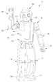
도 1은 본 발명의 일 실시예에 따른 인간형 로봇의 외관을 나타낸 도면이다.
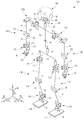
도 2는 도 1의 인간형 로봇의 관절 구조를 나타낸 도면이다.
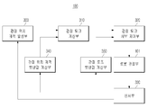
도 3은 본 발명의 일 실시예에 따른 FSM 기반 보행 시 적용하는 로봇 동작 상태 및 제어 동작을 나타낸 도면이다.
도 4는 본 발명의 일 실시예에 따른 인간형 로봇의 제어 블록도이다.
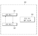
도 5는 도 4의 관절 위치 궤적 발생부의 상세 구성도이다.
도 6은 본 발명의 일 실시예에 따른 관절 위치 궤적 명령을 이용하여 계산된 관절 토크 명령에 따라 모터를 구동하는 동작을 설명하는 블록선도이다.
도 7은 도 4의 관절 토크 서보 제어부의 상세 구성도이다.
도 8은 본 발명의 일 실시예에 따른 관절 토크 명령에 따라 구동하는 모터를 서보 제어하는 동작을 설명하는 블록선도이다.
도 9는 본 발명의 일 실시예에 따른 인간형 로봇의 보행 제어방법을 나타낸 흐름도이다.1 is a view showing the appearance of a humanoid robot according to an embodiment of the present invention.
Fig. 2 is a view showing a joint structure of the humanoid robot of Fig. 1. Fig.
FIG. 3 is a diagram illustrating a robot operation state and a control operation applied when walking on an FSM basis according to an embodiment of the present invention.
4 is a control block diagram of a humanoid robot according to an embodiment of the present invention.
5 is a detailed configuration diagram of the joint position locus generating unit of FIG.
6 is a block diagram illustrating an operation of driving a motor according to an articulated torque command calculated using a joint position trajectory command according to an embodiment of the present invention.
Fig. 7 is a detailed configuration diagram of the joint torque servo control section of Fig. 4;
8 is a block diagram for explaining an operation of servo-controlling a motor driven in accordance with the joint torque command according to an embodiment of the present invention.
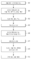
FIG. 9 is a flowchart illustrating a walking control method of a humanoid robot according to an embodiment of the present invention.
이하에서는 첨부도면을 참조하여 본 발명에 대해 상세히 설명한다.Hereinafter, the present invention will be described in detail with reference to the accompanying drawings.
도 1에 도시한 바와 같이, 인간형 로봇(100)의 상체(102) 상부에는 목(120)을 통해 머리(104)가 연결된다. 상체(102) 상부 양측에는 어깨(114L, 114R)를 통해 두 개의 팔(106L, 106R)이 연결된다. 두 개의 팔(106L, 106R) 각각의 말단에는 손(33L, 33R)이 연결된다. 상체(102)의 하부 양측에는 두 개의 다리(110L, 110R)가 연결된다. 두 개의 다리(110L, 110R) 각각의 말단에는 발(112L, 112R)이 연결된다.1, the
머리(104)와 두 개의 팔(106L, 106R), 두 개의 다리(110L, 110R), 각각 두 개씩의 손(33L, 33R)과 발(112L, 112R) 각각은 관절을 통해 일정 수준의 자유도를 갖는다. 상체(102)의 내부는 커버(116)에 의해 보호된다. 참조 부호에서 "R"과 "L"는 각각 로봇(100)의 우측(right)과 좌측(left)을 나타낸다.The
도 2는 도 1에 나타난 로봇의 관절 구조를 나타낸 도면이다. 도 2에 나타낸 바와 같이, 인간형 로봇(100)의 두 개의 다리(110L, 110R)는 각각 대퇴 링크(21)와 하퇴 링크(22), 발(112L, 112R)을 구비한다. 대퇴 링크(21)는 대퇴 관절부(210)를 통해 상체(102)에 연결된다. 대퇴 링크(21)와 하퇴 링크(22)는 무릎 관절부(220)를 통해 서로 연결되고, 하퇴 링크(22)와 발(112L, 112R)은 발목 관절부(230)를 통해 서로 연결된다.FIG. 2 is a view showing a joint structure of the robot shown in FIG. 1. FIG. 2, the two
대퇴 관절부(210)는 3 자유도를 갖는다. 구체적으로 대퇴 관절부(210)는 요유 방향(yaw, Z축 주위의 회전)의 회전 관절(211)과, 피치 방향(pitch, Y축 주위의 회전)의 회전 관절(212), 롤 방향(roll, X축 주위의 회전)의 회전 관절(213)을 갖는다. The femoral
무릎 관절부(220)는 피치 방향의 회전 관절(221)을 포함하여 1 자유도를 가진다. 발목 관절부(230)는 피치 방향의 회전 관절(231)과 롤 방향의 회전 관절(232)을 포함하여 2 자유도를 가진다. The knee joint 220 has a degree of freedom including a rotation joint 221 in the pitch direction. The ankle
두 개의 다리(110L, 110R) 각각에는 세 관절부(210, 220, 230)에 대해 6개의 회전 관절이 마련되므로, 두 개의 다리(110L, 110R) 전체에 대해서는 12개의 회전 관절이 마련된다. Since each of the two
한편 두 개의 다리(110L, 110R)에서 발(112L, 112R)과 발목 관절부(230)의 사이에는 다축 F/T센서(Multi-Axis Force and Torque Sensor)(24)가 각각 설치된다. 다축 F/T 센서(24)는 발(112L, 112R)로부터 전달되는 힘의 3방향 성분(Fx, Fy, Fz)과 모멘트의 3방향 성분(Mx, My, Mz)을 측정함으로써 발(112L, 112R)의 착지여부 및 발(112L, 112R)에 가해지는 하중을 검출할 수 있다. A multi-axis F /
머리(104)에는 주위를 촬영하는 카메라(41)와, 사용자 음성을 입력하는 마이크로폰(42)이 설치된다. The
머리(104)는 목 관절부(280)를 통해 상체(102)와 연결된다. 목 관절부(280)는 요우 방향의 회전 관절(281), 피치 방향의 회전 관절(282) 및 롤 방향의 회전 관절(283)을 포함하여 3 자유도를 가질 수 있다.The
목 관절부(280)의 각각의 회전 관절(281, 282, 283)에는 머리 회전용 모터들(미도시)이 연결된다.Hair turning motors (not shown) are connected to the respective
어깨 관절 어셈블리(250L, 250R)는 상체(102)의 양측에 장착되어 두 개의 팔(106L, 106R)을 상체(102)에 연결한다.The shoulder
두 개의 팔(106L, 106R)은 상박 링크(31), 하박 링크(32) 및 손(33)을 구비한다. 상박 링크(31)는 어깨 관절 어셈블리(250L. 250R)를 통해 상체(102)에 연결된다. 상박 링크(31)와 하박 링크(32)는 팔꿈치 관절부(260)를 통해 서로 연결되고, 하박 링크(32)와 손(33)은 손목 관절부(270)를 통해 서로 연결된다.The two
팔꿈치 관절부(260)는 피치 방향의 회전 관절(261)과, 요우 방향의 회전 관절(262)를 포함하여 2 자유도를 가지고, 손목 관절부(270)는 피치 방향의 회전 관절(271)과 롤 방향의 회전 관절(272)을 포함하여 2 자유도를 가질 수 있다.The elbow
손(33)에는 5개의 손가락(33a)이 설치된다. 각각의 손(33a)에는 모터에 의해 구동되는 다수의 관절(미도시)들이 설치될 수 있다. 손가락(33a)은 팔(106)의 움직임에 연동하여 물건을 파지하거나 특정 방향을 가리키는 것과 같은 다양한 동작을 실행한다.The
상체(102)에는 포즈 센서(pose sensor)(14)가 설치된다. 포즈 센서(14)는 연직축에 대한 상체(102)의 경사 각도와 그 각속도 등을 검출하여 자세 정보를 발생시킨다. 이 포즈 센서(14)는 상체(102) 뿐만 아니라 머리(104)에 설치해도 좋다. 또한 상체(102)를 구성하는 가슴(102a)과 허리(102b) 사이에는 가슴(102a)이 허리(102b)에 대해 회전할 수 있도록 요우 방향의 회전 관절(15)이 설치된다. A
인간형 로봇(100)에는 각 회전 관절을 구동하는 모터(405; 도 6 참조) 등과 같은 액츄에이터가 설치된다. 이 모터(405)를 적절히 제어함으로써 인간형 로봇(100)의 다양한 동작을 구현할 수 있다.The
FSM 기반 보행 제어방법은, 도 3에 예시한 바와 같이, 로봇의 동작 상태를 미리 정의된 6개(S1, S2, S3, S4, S5, S6)로 구분할 수 있다. 각각의 동작 상태는 보행 시 로봇이 취하는 포즈를 의미한다.As shown in FIG. 3, the FSM-based gait control method can divide the operation state of the robot into six predetermined (S1, S2, S3, S4, S5, S6). Each operating state means a pose taken by the robot during walking.
제1상태(flight)(S1)는 다리를 스윙하는 포즈이고, 제2상태(loading)(S2)는 발을 지면에 내려 놓는 포즈이며, 제3상태(heel contact)(S3)는 발 뒤쪽(heel)을 지면에 접촉시키는 포즈이고, 제4상태(heel and toe contact)(S4)는 발 뒤쪽(heel)과 앞쪽(toe)을 동시에 지면에 접촉시키는 포즈이며, 제5상태(toe contact)(S5)는 발 앞쪽(toe)을 접촉시키는 포즈이고, 제6상태(unloading)(S6)는 발을 지면에서 떼어 내는 포즈에 해당한다. The first state (flight) S1 is a pose swinging leg, the second state (loading) S2 is a pose that puts the foot on the ground, and the third state (heel contact) heel and toe contact S4 is a pose that simultaneously brings the heel and the toe into contact with the ground and a fifth state toe contact S5 corresponds to a pose for contacting the toe of the foot, and a sixth state (unloading) S6 corresponds to a pose for disengaging the foot from the ground.
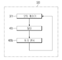
도 4는 본 발명의 일 실시예에 따른 인간형 로봇의 제어 블록도이고, 도 5는 도 4의 관절 위치 궤적 발생부의 상세 구성도이다.FIG. 4 is a control block diagram of a humanoid robot according to an embodiment of the present invention, and FIG. 5 is a detailed block diagram of the joint position locus generating unit of FIG.
도 4에 도시한 바와 같이, 인간형 로봇(100)은 관절 위치 궤적 발생부(300), 관절 토크 계산부(310), 관절 토크 서보 제어부(320), 관절부(101), 센서부(330), 관절 위치 궤적 보상값 계산부(340), 관절 토크 보상값 계산부(350)를 포함한다.4, the
로봇 관절부(101)는 로봇 보행을 위한 두 개의 다리(110L, 110R)의 대퇴 관절부(210), 무릎 관절부(220), 발목 관절부(230) 전체에 대해 12개의 회전 관절을 포함하는 것으로, 이때 두 개의 다리에 속하는 관절만으로 한정되는 것은 아니고 안정적인 보행을 위해 상체와 팔 등 인간형 로봇(100)의 모든 관절을 포함할 수 있다.The robot
센서부(330)는 상체(102)에 설치된 포즈 센서(14)와 발목 관절부(230)에 설치된 다축 F/T 센서(24)와, 로봇 관절부(101)의 각 관절에 설치된 모터(405)의 회전을 측정하는 엔코더(405b)를 포함한다. The
관절 위치 궤적 발생부(300)가 센서부(330)의 측정값을 이용하여 각 관절의 위치 궤적 명령 (![]()
![]()
도 5에서 관절 위치 궤적 발생부(300)는 상태 머신 1(301), 상태 머신 2(302), 관절 위치 궤적 계산부(303)를 포함한다.5, the joint position
상태 머신 1(301)과 상태 머신(302)는 오른발 또는 왼발이 지면에 착지할 경우 발목 관절부(230)에 설치된 F/T 센서(24)의 착지 신호에 따라 서로 스위칭을 한다. 왼발이 스윙하고 오른발이 착지 상태이면 상태 머신 2(302)에서 상태 머신 1(301)로 스위칭하고, 오른발이 스윙하고 왼발이 착지 상태이면 상태 머신 1(301)에서 상태 머신 2(302)로 스위칭한다.The
관절 위치 궤적 계산부(303)는 상태 머신 1(301)과 상태 머신2(302)의 스위칭에 따라 왼발과 오른발의 착지 상태를 판단하여 로봇 관절부(101)의 각 관절의 위치 궤적 명령 (![]()
![]()
관절 위치 궤적 명령(![]()
![]()
관절 토크 계산부(310)는 각 관절의 위치 궤적 명령 (![]()
![]()
![]()
![]()
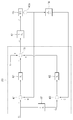
도 6은 본 발명의 일 실시예에 따른 관절 위치 궤적 명령을 이용하여 계산된 관절 토크 명령에 따라 모터를 구동하는 동작을 설명하는 블록선도이다. 6 is a block diagram illustrating an operation of driving a motor according to an articulated torque command calculated using a joint position trajectory command according to an embodiment of the present invention.
도 6에서, 제1위치 연산기(401)가 관절 위치 궤적 명령 (![]()
![]()
![]()
![]()
![]()
![]()
![]()
![]()
![]()
![]()
비례 게인 제어기(402)가 감산값 (![]()
![]()
![]()
![]()
![]()
![]()
![]()
![]()
제3위치 연산기(408)가 미분 제어기(407)에 의해 미분된 관절 위치 궤적 명령(![]()
![]()
![]()
![]()
![]()
![]()
![]()
![]()
![]()
![]()
![]()
![]()
![]()
![]()
![]()
![]()
![]()
![]()
![]()
![]()
제2위치 연산기(403)는 두 곱셈값(![]()
![]()
![]()
![]()
![]()
![]()
![]()
![]()
![]()
![]()
![]()
![]()
![]()
![]()
![]()
![]()
![]()
![]()
![]()
![]()
![]()
![]()
![]()
![]()
![]()
![]()
식 1은 비례 미분(PD) 제어기와 피드 포워드(FF) 제어기를 이용한 것이나, 이에 한정하는 것은 아니며 각 관절의 위치(![]()
![]()
![]()
![]()
관절 토크 명령(![]()
![]()
![]()
![]()
![]()
![]()
도 7에서, 관절 토크 서보 제어부(320)는 모터 제어기(321)를 포함한다. 모터 제어기(321)는 토크 센서(405b)에 의해 측정된 관절 토크값을 피드백받아 관절 토크 명령(![]()
![]()
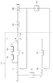
도 8은 본 발명의 일 실시예에 따른 관절 토크 명령에 따라 구동하는 모터를 서보 제어하는 동작을 설명하는 블록선도이다. 8 is a block diagram for explaining an operation of servo-controlling a motor driven in accordance with the joint torque command according to an embodiment of the present invention.
도 8에서, 제1토크 연산기(501)가 상기 각 관절의 토크 명령 (![]()
![]()
![]()
![]()
![]()
![]()
![]()
![]()
![]()
![]()
![]()
![]()
적분기(503)는 감산값 (![]()
![]()
![]()
![]()
![]()
![]()
![]()
![]()
제3토크 연산기(508)가 미분 제어기(507)에 의해 미분된 관절 토크 명령(![]()
![]()
![]()
![]()
![]()
![]()
![]()
![]()
![]()
![]()
![]()
![]()
제2토크 연산기(505)는 세 곱셈값(![]()
![]()
![]()
![]()
![]()
![]()
![]()
![]()
![]()
![]()
![]()
![]()
식 2은 비례 적분 미분(PID) 제어기와 피드 포워드(FF) 제어기를 이용한 것이나, 이에 한정하는 것은 아니며 각 관절의 위치(![]()
![]()
![]()
![]()
이와 같이 관절 토크 서보 제어부(320)에 의해 로봇 관절부(101)가 토크 서보 제어에 기반하여 보행 동작을 실행할 수 있다.In this manner, the joint
로봇의 포즈를 전환하여 보행 시 보행면의 상태, 장애물의 출현 등 주위 환경에 따라 보행 제어가 부적절하여 로봇이 균형을 잃을 수 있기 때문에, 인간형 로봇에 있어서는 주위 환경과 상호 작용하는 정보와 로봇의 자세 정보를 피드백 받아서 관절 위치 궤적 명령과 관절 토크 명령을 보상하여 보행 동작을 안정적으로 제어할 필요가 있다.The robot can lose balance due to the inadequate walking control in accordance with the surrounding environment such as the state of the walking surface and the appearance of the obstacle at the time of walking by switching the pose of the robot. Therefore, in the humanoid robot, It is necessary to stably control the walking operation by compensating the joint position trajectory command and the joint torque command by receiving the information.
도 4에서 관절 위치 궤적 보상값 계산부(340)가 센서부(330)에 의해 측정된 값을 이용하여 관절 위치 궤적 명령을 보상하기 위한 관절 위치 궤적 보상값을 생성하여 관절 토크 계산부(310)에 제공한다. 즉, 로봇의 발이 지면에 접촉 시 관절 위치 궤적 보상값 계산부(340)가 다축 F/T 센서(24)로부터 힘과 모멘트 정보를 입력받고, 포즈 센서(14)로부터 로봇의 자세 정보를 입력받아 관절 위치 궤적 보상값(![]()
![]()
그러면 관절 토크 계산부(310)는 식 3과 같은 보상된 관절 위치 궤적 명령(![]()
![]()
![]()
![]()
여기서 ![]()
![]()
![]()
![]()
![]()
![]()
![]()
![]()
![]()
![]()
![]()
![]()
![]()
![]()
![]()
![]()
식 4는 관절 위치 궤적 보상값(![]()
![]()
관절 위치 궤적 보상값(![]()
![]()
![]()
![]()
![]()
![]()
![]()
![]()
![]()
![]()
![]()
![]()
![]()
![]()
![]()
![]()
![]()
![]()
![]()
![]()
![]()
![]()
이외에 관절 위치 궤적 보상값(![]()
![]()
![]()
![]()
![]()
![]()
![]()
![]()
![]()
![]()
관절 토크 보상값 계산부(350)는 센서부(330)에 의해 측정된 값을 이용하여 관절 토크 명령을 보상하기 위한 관절 토크 보상값을 생성하여 관절 토크 서보 제어부(320)에 제공한다. 즉, 로봇의 발이 지면에 접촉 시 관절 토크 보상값 계산부(350)가 다축 F/T 센서(24)로부터 힘과 모멘트 정보를 입력받고, 포즈 센서(14)로부터 로봇의 자세 정보를 입력받아 관절 토크 보상값(![]()
![]()
그러면 관절 토크 서보 제어부(320)는 식 5와 같은 보상된 관절 토크 명령(![]()
![]()
![]()
![]()
여기서 ![]()
![]()
![]()
![]()
![]()
![]()
![]()
![]()
![]()
![]()
![]()
![]()
![]()
![]()
![]()
![]()
식 6은 관절 토크 보상값(![]()
![]()
관절 토크 보상값(![]()
![]()
![]()
![]()
![]()
![]()
![]()
![]()
![]()
![]()
![]()
![]()
![]()
![]()
![]()
![]()
![]()
![]()
![]()
![]()
![]()
![]()
이외에 관절 토크 보상값(![]()
![]()
![]()
![]()
![]()
![]()
![]()
![]()
![]()
![]()
실시예에서는 관절 위치 궤적 명령과 관절 토크 명령을 모두 보상하였으나, 관절 위치 궤적 명령과 관절 토크 명령 중 어느 하나를 보상하는 방식을 적용하여 인간형 로봇의 안정적인 보행 동작을 구현할 수도 있다.In the embodiment, both the joint position trajectory command and the joint torque command are compensated. However, a stable walking operation of the humanoid robot can be implemented by applying a method of compensating for either the joint position trajectory command or the joint torque command.
이하에서는 본 발명의 일 실시예에 따른 인간형 로봇의 보행 제어방법을 설명한다.Hereinafter, a walking control method for a humanoid robot according to an embodiment of the present invention will be described.
기본적으로 FSM에 기반하여 인간형 로봇(100)이 보행한다. 보행 동작을 실행하려면 관절 위치 궤적 계산부(303)가 센서부(300)의 측정값을 이용하여 왼발과 오른발의 착지 상태를 판단하여 로봇 관절부(101)의 각 관절의 위치 궤적 명령 (![]()
![]()
![]()
![]()
계산된 관절 위치 궤적 명령(![]()
![]()
관절 위치 궤적 보상부(340)가 다축 F/T 센서(24)로부터 힘과 모멘트 정보를 입력받고, 포즈 센서(14)로부터 로봇의 자세 정보를 입력받아 관절 위치 궤적 보상값(![]()
![]()
![]()
![]()
![]()
![]()
![]()
![]()
![]()
![]()
![]()
![]()
![]()
![]()
계산된 관절 위치 궤적 보상값(![]()
![]()
![]()
![]()
![]()
![]()
![]()
![]()
관절 토크 보상값 계산부(350)가 다축 F/T 센서(24)로부터 힘과 모멘트 정보를 입력받고, 포즈 센서(14)로부터 로봇의 자세 정보를 입력받아 관절 토크 보상값(![]()
![]()
![]()
![]()
![]()
![]()
![]()
![]()
![]()
![]()
![]()
![]()
![]()
![]()
계산된 관절 토크 보상값(![]()
![]()
![]()
![]()
![]()
![]()
![]()
![]()
모터 구동 시 관절 토크 서보 제어부(320)는 토크 센서(405b)에 의해 측정된 관절 토크값을 피드백받아 관절 토크 명령(![]()
![]()
When the motor is driven, the joint torque ![]()
![]()
300 : 관절 위치 궤적 발생부
310 : 관절 토크 계산부
320 : 관절 토크 서보 제어부
330 : 센서부
340 : 관절 위치 궤적 보상값 계산부
350 : 관절 토크 보상값 계산부300: joint position locus generator
310: joint torque calculation unit
320: Joint torque servo control unit
330:
340: Joint position locus compensation value calculation unit
350: Joint torque compensation value calculation unit
Claims (17)
상기 로봇의 착지 정보와 자세 정보를 측정하는 센서부;
상기 로봇의 착지 정보와 자세 정보를 이용하여 상기 각 관절의 위치 궤적을 발생하는 관절 위치 궤적 발생부;
상기 각 관절의 위치 궤적을 보상하기 위한 관절 위치 궤적 보상값을 계산하는 관절 위치 궤적 보상값 계산부;
상기 관절 위치 궤적 보상값을 이용하여 상기 각 관절의 위치 궤적을 보상하고, 보상된 각 관절의 위치 궤적에 따라 각 관절의 관절 토크를 계산하는 관절 토크 계산부;
상기 각 관절의 관절 토크를 보상하기 위한 관절 토크 보상값을 계산하는 관절 토크 보상값 계산부;
상기 관절 토크 보상값을 이용하여 상기 각 관절의 토크 명령을 보상하고, 보상된 각 관절의 토크 명령을 추종하도록 모터 전류를 계산하고, 계산된 모터 전류에 따라 상기 각 관절에 설치된 모터의 토크를 서보 제어하는 관절 토크 서보 제어부;를 포함하는 인간형 로봇.
A robot joint including movable joints when the robot is walking;
A sensor unit for measuring landing information and attitude information of the robot;
A joint position locus generating unit for generating a position locus of each joint using the landing information and attitude information of the robot;
A joint position locus compensation value calculation unit for calculating a joint position locus compensation value for compensating the position locus of each joint;
A joint torque calculation unit for compensating a position locus of each joint using the joint position locus compensation value and calculating a joint torque of each joint according to a position locus of each compensated joint;
A joint torque compensation value calculation unit for calculating a joint torque compensation value for compensating the joint torque of each joint;
A torque command of each joint is compensated by using the joint torque compensation value, a motor current is calculated so as to follow a torque command of each compensated joint, and a torque of a motor installed in each joint according to the calculated motor current, And a joint torque servo control unit for controlling the joint torque servo control unit.
상기 센서부가 로봇의 착지 상태를 측정하기 위한 다축 F/T 센서와 상기 로봇의 자세를 측정하기 위한 포즈 센서를 포함하는 인간형 로봇.
The method according to claim 1,
Wherein the sensor unit includes a multi-axis F / T sensor for measuring a landing state of the robot and a pose sensor for measuring the posture of the robot.
상기 관절 위치 궤적 발생부가 왼발 또는 오른발이 지면에 착지할 경우 서로 스위칭하는 복수의 상태 머신과, 상기 복수의 상태 머신의 스위칭에 따라 왼발 또는 오른발의 착지 상태를 판단하여 상기 각 관절의 관절 위치 궤적 명령을 계산하는 관절 위치 궤적 계산부를 포함하는 인간형 로봇.
The method according to claim 1,
A plurality of state machines for switching the joint position locus generation unit when the left or right foot is landed on the ground; and a control unit for determining a landing state of the left or right foot according to the switching of the plurality of state machines, And a joint position locus calculating section for calculating a joint locus locus calculating section.
상기 관절 토크 계산부가 제1 내지 제3위치 연산기, 비례 게인 제어기, 미분 게인 제어기를 포함하여 식 1과 같이 상기 각 관절의 관절 토크 명령(
상기 제1위치 연산기는 관절 위치 궤적 명령 (
상기 비례 게인 제어기는 상기 감산값 (
상기 제3위치 연산기는 미분된 관절 위치 궤적 명령(
상기 미분 게인 제어기는 상기 감산값(
상기 제2위치 연산기는 두 곱셈값(
The method according to claim 1,
The joint torque calculation unit includes first to third position calculators, a proportional gain controller, and a differential gain controller, and calculates a joint torque command
The first position calculator calculates a joint position trajectory command (
The proportional gain controller calculates the subtraction value
The third position calculator is operable to calculate a differentiated joint position trajectory command (
Wherein the differential gain controller outputs the subtraction value (
The second position calculator calculates two multiplication values (
상기 센서부가 상기 모터에 설치된 엔코더를 더 포함하고,
상기 엔코더로 상기 현재 관절 위치 (
5. The method of claim 4,
Wherein the sensor unit further comprises an encoder provided in the motor,
The current joint position (
상기 관절 토크 서보 제어부는 모터 제어기와 상기 모터의 토크를 측정하는 토크 센서를 포함하고,
상기 모터 제어기는 상기 토크 센서에 의해 측정된 관절 토크값을 피드백받아 상기 각 관절의 토크 명령을 추종하도록 상기 모터를 구동시키는 인간형 로봇.
The method according to claim 1,
Wherein the joint torque servo control section includes a motor controller and a torque sensor for measuring a torque of the motor,
Wherein the motor controller receives the joint torque value measured by the torque sensor and drives the motor so as to follow the torque command of each joint.
상기 모터 제어기는 제1 내지 제3토크 연산기, 비례 게인 제어기, 적분기, 적분 게인 제어기, 미분 게인 제어기를 포함하여 식 2와 같이 모터 전류(
상기 제1토크 연산기는 관절 토크 명령 (
상기 비례 게인 제어기가 상기 감산값 (
상기 적분기가 상기 감산값 (
상기 적분 게인 제어기가 적분한 감산값(
상기 제3토크 연산기가 미분된 관절 토크 명령(
상기 미분 게인 제어기가 상기 감산값(
상기 제2토크 연산기가 상기 곱셈값(
The method according to claim 6,
The motor controller includes a first to a third torque calculator, a proportional gain controller, an integrator, an integral gain controller, and a differential gain controller,
The first torque calculator includes a joint torque command
Wherein the proportional gain controller outputs the subtraction value
The integrator decreasing the subtraction value (
The subtraction value integrated by the integral gain controller (
Wherein the third torque calculator is operable to calculate a differentiated joint torque command
Wherein the differential gain controller outputs the subtraction value (
The second torque calculator calculates the multiplication value (
상기 센서부가 상기 로봇의 착지 상태를 측정하기 위한 다축 F/T 센서와 상기 로봇의 자세를 측정하기 위한 포즈 센서를 포함하고,
상기 관절 위치 궤적 보상값 계산부가 로봇의 발이 지면에 접촉 시 상기 다축 F/T 센서로부터 힘과 모멘트 정보를 입력받고, 상기 포즈 센서로부터 로봇의 자세 정보를 입력받아 관절 위치 궤적 보상값(
상기 관절 토크 계산부가 상기 관절 위치 궤적 보상값(
여기서
The method according to claim 1,
Wherein the sensor unit includes a multi-axis F / T sensor for measuring a landing state of the robot and a pose sensor for measuring a posture of the robot,
The joint position locus compensation value calculation unit receives force and moment information from the multi-axis F / T sensor when the foot of the robot contacts the ground, receives the position information of the robot from the pose sensor,
The joint torque calculation unit calculates the joint position locus compensation value (
here
상기 관절 위치 궤적 보상값은 식 4와 같이 계산되는 인간형 로봇.
여기서,
9. The method of claim 8,
And the joint position locus compensation value is calculated as shown in Equation (4).
here,
상기 센서부가 상기 로봇의 착지 상태를 측정하기 위한 다축 F/T 센서와 상기 로봇의 자세를 측정하기 위한 포즈 센서를 포함하고,
상기 관절 토크 보상값 계산부가 로봇의 발이 지면에 접촉 시 상기 다축 F/T 센서로부터 힘과 모멘트 정보를 입력받고, 상기 포즈 센서로부터 로봇의 자세 정보를 입력받아 관절 토크 보상값(
상기 관절 토크 서보 제어부가 식 5와 같은 보상된 관절 토크 명령(
여기서
The method according to claim 1,
Wherein the sensor unit includes a multi-axis F / T sensor for measuring a landing state of the robot and a pose sensor for measuring a posture of the robot,
The joint torque compensation value calculation unit receives the force and moment information from the multi-axis F / T sensor when the foot of the robot contacts the ground, receives the attitude information of the robot from the pose sensor,
The joint torque servo control unit calculates the compensated joint torque command (
here
상기 관절 토크 보상값은 식 6과 같이 계산되는 인간형 로봇.
여기서
11. The method of claim 10,
And the joint torque compensation value is calculated as shown in Equation (6).
here
상기 로봇에 설치된 센서로 측정한 상기 로봇의 착지 정보와 자세 정보를 이용하여 상기 각 관절의 위치 궤적을 보상하기 위한 관절 위치 궤적 보상값을 계산하고;
상기 관절 위치 궤적 보상값을 이용하여 보상한 관절 위치 궤적에 따라 상기 각 관절의 토크를 계산하고;
상기 로봇에 설치된 센서로 측정한 상기 로봇의 착지 정보와 자세 정보를 이용하여 상기 각 관절의 관절 토크를 보상하기 위한 관절 토크 보상값을 계산하고;
상기 관절 토크 보상값을 이용하여 보상한 관절 토크 명령을 추종하도록 모터 전류를 계산하고, 계산된 모터 전류에 따라 각 관절에 설치된 모터의 토크를 서보 제어하는 것;을
포함하는 인간형 로봇의 보행 제어방법.
Calculating joint locus loci of each joint for walking of the robot;
Calculating joint position locus compensation values for compensating position locus of each joint using landing information and attitude information of the robot measured by a sensor installed in the robot;
Calculating a torque of each joint according to a joint position locus compensated using the joint position locus compensation value;
Calculating joint torque compensation values for compensating joint torques of the respective joints using landing information and attitude information of the robot measured by a sensor installed in the robot;
Calculating a motor current so as to follow the compensated joint torque command using the joint torque compensation value and servo-controlling the torque of the motor installed in each joint according to the calculated motor current;
A walking control method of a humanoid robot including the robot.
상기 관절 위치 궤적을 계산하는 것은 왼발 또는 오른발이 지면에 착지한 상태를 판단하여 상기 각 관절의 관절 위치 궤적 명령을 계산하는 것을 포함하는 인간형 로봇의 보행 제어방법.
13. The method of claim 12,
Wherein calculating the joint position trajectory includes calculating a joint position trajectory command of each joint by determining whether the left or right foot is landed on the ground.
상기 각 관절의 토크를 계산하는 것은
각 관절의 관절 위치 궤적 명령 (
13. The method of claim 12,
The calculation of the torque of each joint
Joint position trajectory command of each joint (
상기 모터 전류를 계산하는 것은
관절 토크 명령 (
13. The method of claim 12,
Calculating the motor current
Joint Talk Command (
상기 로봇의 착지 상태를 측정하기 위한 다축 F/T 센서로부터 힘과 모멘트 정보를 입력받고, 상기 로봇의 자세를 측정하기 위한 포즈 센서로부터 로봇의 자세 정보를 입력받아 상기 관절 위치 궤적 보상값을 계산하되,
상기 관절 위치 궤적 보상값(
상기 보상된 관절 위치 궤적 명령(
13. The method of claim 12,
A force and moment information is received from a multi-axis F / T sensor for measuring the landing state of the robot, and the posture information of the robot is received from a pose sensor for measuring the posture of the robot to calculate the joint position locus compensation value ,
The joint position locus compensation value (
The compensated joint position trajectory command (
상기 로봇의 착지 상태를 측정하기 위한 다축 F/T 센서로부터 힘과 모멘트 정보를 입력받고, 상기 로봇의 자세를 측정하기 위한 포즈 센서로부터 로봇의 자세 정보를 입력받아 상기 관절 토크 보상값을 계산하되,
상기 관절 토크 보상값(
상기 보상된 관절 토크 명령(
Wherein the force and moment information is received from a multiaxial F / T sensor for measuring the landing state of the robot, and the posture information of the robot is received from a pose sensor for measuring the posture of the robot to calculate the joint torque compensation value,
The joint torque compensation value (
The compensated joint torque command (
Priority Applications (5)
| Application Number | Priority Date | Filing Date | Title |
|---|---|---|---|
| KR1020100004285A KR101633362B1 (en) | 2010-01-18 | 2010-01-18 | Humanoid robot and walking control method thereof |
| CN201110021731.0A CN102139714B (en) | 2010-01-18 | 2011-01-14 | Humanoid robot and walking control method thereof |
| US13/006,782 US8676381B2 (en) | 2010-01-18 | 2011-01-14 | Humanoid robot and walking control method thereof |
| JP2011007244A JP5916998B2 (en) | 2010-01-18 | 2011-01-17 | Humanoid robot and its walking control method |
| EP11151201A EP2347868B1 (en) | 2010-01-18 | 2011-01-18 | Humanoid robot and walking control method thereof |
Applications Claiming Priority (1)
| Application Number | Priority Date | Filing Date | Title |
|---|---|---|---|
| KR1020100004285A KR101633362B1 (en) | 2010-01-18 | 2010-01-18 | Humanoid robot and walking control method thereof |
Publications (2)
| Publication Number | Publication Date |
|---|---|
| KR20110084630A KR20110084630A (en) | 2011-07-26 |
| KR101633362B1 true KR101633362B1 (en) | 2016-06-28 |
Family
ID=43859720
Family Applications (1)
| Application Number | Title | Priority Date | Filing Date |
|---|---|---|---|
| KR1020100004285A KR101633362B1 (en) | 2010-01-18 | 2010-01-18 | Humanoid robot and walking control method thereof |
Country Status (5)
| Country | Link |
|---|---|
| US (1) | US8676381B2 (en) |
| EP (1) | EP2347868B1 (en) |
| JP (1) | JP5916998B2 (en) |
| KR (1) | KR101633362B1 (en) |
| CN (1) | CN102139714B (en) |
Families Citing this family (53)
| Publication number | Priority date | Publication date | Assignee | Title |
|---|---|---|---|---|
| KR20110082394A (en) * | 2010-01-11 | 2011-07-19 | 삼성전자주식회사 | Walking robot and control method thereof |
| US9119655B2 (en) * | 2012-08-03 | 2015-09-01 | Stryker Corporation | Surgical manipulator capable of controlling a surgical instrument in multiple modes |
| CN103517789B (en) * | 2011-05-12 | 2015-11-25 | 株式会社Ihi | motion prediction control device and method |
| FR2978844B1 (en) * | 2011-08-04 | 2014-03-21 | Aldebaran Robotics | ROBOT WITH ARTICULATIONS OF VARIABLE RIGIDITY AND METHOD OF CALCULATING SAID OPTIMIZED RIGIDITY |
| CN102426391B (en) * | 2011-09-05 | 2014-06-11 | 华南理工大学 | Method for determining whether there is collision during robot operation |
| KR101288149B1 (en) * | 2011-11-02 | 2013-07-18 | 명지대학교 산학협력단 | Device and method for controlling the balance of biped walking robots |
| JP6305673B2 (en) * | 2011-11-07 | 2018-04-04 | セイコーエプソン株式会社 | Robot control system, robot system and robot |
| CN103197671A (en) * | 2012-01-04 | 2013-07-10 | 中国人民解放军第二炮兵工程学院 | Humanoid robot gait planning and synthesizing method |
| KR101985790B1 (en) * | 2012-02-21 | 2019-06-04 | 삼성전자주식회사 | Walking robot and control method thereof |
| CN102658548A (en) * | 2012-05-04 | 2012-09-12 | 北京理工大学 | Waist movement planning method and device for preventing humanoid robot from tilting back and forth |
| KR101326957B1 (en) * | 2012-05-15 | 2013-11-13 | 현대자동차주식회사 | Method for controlling ankle of robot |
| US9226796B2 (en) | 2012-08-03 | 2016-01-05 | Stryker Corporation | Method for detecting a disturbance as an energy applicator of a surgical instrument traverses a cutting path |
| KR102530836B1 (en) | 2012-08-03 | 2023-05-10 | 스트리커 코포레이션 | Systems and methods for robotic surgery |
| CN103279967B (en) * | 2013-05-09 | 2016-02-24 | 四三九九网络股份有限公司 | Mobile terminal is applied the method and apparatus of reverse dynamics simulation true man action |
| JP6330287B2 (en) * | 2013-10-29 | 2018-05-30 | セイコーエプソン株式会社 | Robot, robot contact member |
| CN104260107B (en) * | 2014-09-04 | 2016-03-30 | 北京邮电大学 | The method of a kind of implementation space mechanical arm flexible joint compensation of gear clearance |
| KR102365191B1 (en) | 2014-10-20 | 2022-02-18 | 삼성전자주식회사 | Method and apparatus for recognizing user motion |
| US10576619B2 (en) * | 2014-12-26 | 2020-03-03 | Samsung Electronics Co., Ltd. | Assisting torque setting method and apparatus |
| CN104793621B (en) * | 2015-05-12 | 2017-11-14 | 北京理工大学 | A kind of Humanoid Robot Based on Walking stable control method for imitating muscle viscous-elastic behaviour |
| US9594377B1 (en) * | 2015-05-12 | 2017-03-14 | Google Inc. | Auto-height swing adjustment |
| CN104950888B (en) * | 2015-06-19 | 2017-10-24 | 武汉理工大学 | Ten seven freedom anthropomorphic robots and its control method |
| CN105446345A (en) * | 2015-07-02 | 2016-03-30 | 浙江大学 | Control system of humanoid biped robot |
| JP6332197B2 (en) * | 2015-08-11 | 2018-05-30 | トヨタ自動車株式会社 | Motor control device |
| CN105033997B (en) * | 2015-09-15 | 2017-06-13 | 北京理工大学 | A kind of anthropomorphic robot sharp work whole body planning and control method |
| CN105329333B (en) * | 2015-11-20 | 2017-09-26 | 清华大学 | The non-monocycle gait control method of biped robot's walking based on Delay Feedback |
| JP2017144512A (en) * | 2016-02-17 | 2017-08-24 | 国立大学法人 東京大学 | Zmp calculation method and device |
| WO2018030734A1 (en) * | 2016-08-09 | 2018-02-15 | 주식회사 비플렉스 | 3d simulation method and apparatus |
| CN106625665B (en) * | 2016-12-15 | 2019-03-12 | 北京卫星制造厂 | A kind of drilling milling machine device people's system of packaged type automatic addressing |
| EP3554414A1 (en) | 2016-12-16 | 2019-10-23 | MAKO Surgical Corp. | Techniques for modifying tool operation in a surgical robotic system based on comparing actual and commanded states of the tool relative to a surgical site |
| EP3424650B1 (en) | 2017-07-07 | 2022-12-21 | Siemens Aktiengesellschaft | A method and apparatus for performing control of a movement of a robot arm |
| CN109693235B (en) * | 2017-10-23 | 2020-11-20 | 中国科学院沈阳自动化研究所 | Human eye vision-imitating tracking device and control method thereof |
| CN110053039B (en) * | 2018-01-17 | 2021-10-29 | 深圳市优必选科技有限公司 | Gravity compensation method and device in robot walking and robot |
| CN108333971B (en) * | 2018-02-28 | 2020-06-12 | 清华大学 | Collaborative optimization method for structure and motion of humanoid robot |
| US11691293B2 (en) | 2018-08-31 | 2023-07-04 | Fanuc Corporation | Robot |
| CN109176596B (en) * | 2018-11-16 | 2024-04-19 | 上海岭先机器人科技股份有限公司 | Integrated joint with elastic moment compensation element |
| CN109850293A (en) * | 2018-12-12 | 2019-06-07 | 楚天科技股份有限公司 | A kind of robot film cutting apparatus and the flexible method for cutting film |
| CN111377004B (en) * | 2018-12-28 | 2021-11-16 | 深圳市优必选科技有限公司 | Biped robot gait control method and biped robot |
| CN109634100B (en) * | 2018-12-30 | 2021-11-02 | 深圳市优必选科技有限公司 | Humanoid robot walking acceleration compensation method and device and humanoid robot |
| CN110053043B (en) * | 2019-03-05 | 2021-10-26 | 华南理工大学 | Industrial robot collision detection method and device, electronic equipment and medium |
| US11745902B1 (en) * | 2019-12-11 | 2023-09-05 | Government Of The United States As Represented By The Secretary Of The Air Force | Systems, methods and apparatus for multifunctional central pattern generator |
| CN110936393B (en) * | 2019-12-23 | 2020-09-04 | 山东省产品质量检验研究院 | Basketball motion gesture learning robot |
| CN113050409B (en) * | 2019-12-28 | 2023-12-01 | 深圳市优必选科技股份有限公司 | Humanoid robot, control method thereof and computer-readable storage medium |
| CN113156926B (en) * | 2020-01-22 | 2024-05-17 | 深圳市优必选科技股份有限公司 | Method for establishing finite state machine of robot, finite state machine and robot |
| CN111358377B (en) * | 2020-04-28 | 2021-06-01 | 安徽省春谷3D打印智能装备产业技术研究院有限公司 | Sweeping robot auxiliary device capable of changing airflow direction to clean dead corners |
| CN111504682B (en) * | 2020-05-15 | 2022-05-24 | 深圳国信泰富科技有限公司 | Robot joint torque feasibility detection method and system |
| CN111558941B (en) * | 2020-07-14 | 2020-09-29 | 深圳市优必选科技股份有限公司 | Floating base dynamics feedforward control method and device and multi-legged robot |
| CN111891253B (en) * | 2020-09-02 | 2023-12-15 | 上海微电机研究所(中国电子科技集团公司第二十一研究所) | Four-foot robot |
| CN114425770A (en) * | 2020-10-29 | 2022-05-03 | 北京配天技术有限公司 | Industrial robot teaching control method, electronic equipment and storage medium |
| US11712804B2 (en) | 2021-03-29 | 2023-08-01 | Samsung Electronics Co., Ltd. | Systems and methods for adaptive robotic motion control |
| US11724390B2 (en) | 2021-03-29 | 2023-08-15 | Samsung Electronics Co., Ltd. | Systems and methods for automated preloading of actuators |
| US11731279B2 (en) | 2021-04-13 | 2023-08-22 | Samsung Electronics Co., Ltd. | Systems and methods for automated tuning of robotics systems |
| CN114227658A (en) * | 2021-12-15 | 2022-03-25 | 北京哈崎机器人科技有限公司 | Robot control method, system, terminal and medium |
| CN114516052B (en) * | 2022-03-23 | 2023-12-22 | 杭州湖西云百生科技有限公司 | Dynamics control method and system for parallel real-time high-performance multi-axis mechanical arm |
Citations (1)
| Publication number | Priority date | Publication date | Assignee | Title |
|---|---|---|---|---|
| JP2003236783A (en) | 2002-02-18 | 2003-08-26 | Japan Science & Technology Corp | Bipedal walking transfer device |
Family Cites Families (10)
| Publication number | Priority date | Publication date | Assignee | Title |
|---|---|---|---|---|
| GB0104995D0 (en) | 2001-02-28 | 2001-04-18 | Isis Innovation | Artificial morpho-functional multiped and motion controller therefor |
| JP4188607B2 (en) * | 2001-06-27 | 2008-11-26 | 本田技研工業株式会社 | Method for estimating floor reaction force of bipedal mobile body and method for estimating joint moment of bipedal mobile body |
| JP3574952B2 (en) | 2002-02-18 | 2004-10-06 | 独立行政法人 科学技術振興機構 | Bipod walking type moving device and its walking control device |
| KR100977348B1 (en) | 2002-03-15 | 2010-08-20 | 소니 주식회사 | Operation control device for leg-type mobile robot and operation control method, and robot device |
| JP4587738B2 (en) * | 2003-08-25 | 2010-11-24 | ソニー株式会社 | Robot apparatus and robot posture control method |
| US7313463B2 (en) * | 2005-03-31 | 2007-12-25 | Massachusetts Institute Of Technology | Biomimetic motion and balance controllers for use in prosthetics, orthotics and robotics |
| US7211979B2 (en) * | 2005-04-13 | 2007-05-01 | The Broad Of Trustees Of The Leland Stanford Junior University | Torque-position transformer for task control of position controlled robots |
| JP4840239B2 (en) * | 2007-04-20 | 2011-12-21 | トヨタ自動車株式会社 | Control method for legged mobile robot and legged mobile robot |
| US7986118B2 (en) * | 2007-04-23 | 2011-07-26 | Honda Motor Co., Ltd. | Open-loop torque control on joint position-controlled robots |
| CN101298260B (en) * | 2008-06-11 | 2010-06-02 | 清华大学 | Low-power consumption two-foot walking moving system and walking control method thereof |
-
2010
- 2010-01-18 KR KR1020100004285A patent/KR101633362B1/en active IP Right Grant
-
2011
- 2011-01-14 CN CN201110021731.0A patent/CN102139714B/en active Active
- 2011-01-14 US US13/006,782 patent/US8676381B2/en active Active
- 2011-01-17 JP JP2011007244A patent/JP5916998B2/en active Active
- 2011-01-18 EP EP11151201A patent/EP2347868B1/en active Active
Patent Citations (1)
| Publication number | Priority date | Publication date | Assignee | Title |
|---|---|---|---|---|
| JP2003236783A (en) | 2002-02-18 | 2003-08-26 | Japan Science & Technology Corp | Bipedal walking transfer device |
Also Published As
| Publication number | Publication date |
|---|---|
| EP2347868A1 (en) | 2011-07-27 |
| KR20110084630A (en) | 2011-07-26 |
| US8676381B2 (en) | 2014-03-18 |
| US20110178639A1 (en) | 2011-07-21 |
| CN102139714B (en) | 2014-11-05 |
| JP5916998B2 (en) | 2016-05-11 |
| CN102139714A (en) | 2011-08-03 |
| JP2011143536A (en) | 2011-07-28 |
| EP2347868B1 (en) | 2012-09-19 |
Similar Documents
| Publication | Publication Date | Title |
|---|---|---|
| KR101633362B1 (en) | Humanoid robot and walking control method thereof | |
| KR101687629B1 (en) | Humanoid robot and walking control method thereof | |
| KR101985790B1 (en) | Walking robot and control method thereof | |
| EP2347867B1 (en) | Walking control apparatus of robot and method of controlling the same | |
| KR101549817B1 (en) | robot walking control apparatus and method thereof | |
| JP5607886B2 (en) | Walking robot and control method thereof | |
| KR101687628B1 (en) | Walking control apparatus of robot and method for controlling the same | |
| KR101732901B1 (en) | Walking robot and control method thereof | |
| KR101809972B1 (en) | Walking robot and control method thereof | |
| JP4998506B2 (en) | Robot control device, robot control method, and legged robot | |
| KR101687630B1 (en) | Walking robot and method for controlling balancing the same | |
| JP2013126711A (en) | Walking robot and control method thereof | |
| KR20110082394A (en) | Walking robot and control method thereof | |
| US20080065269A1 (en) | Controller of Leg Type Moving Robot | |
| KR101766755B1 (en) | Walking robot and control method thereof | |
| KR20130049029A (en) | Walking robot and control method for thereof | |
| KR20120069333A (en) | Walking control apparatus of robot and method for controlling the same | |
| KR20120024098A (en) | Walking robot and control method thereof | |
| JPWO2007139135A1 (en) | Robot and control device | |
| KR101760883B1 (en) | Robot and control method thereof | |
| Khorram et al. | Dynamics modeling and stable gait planning of a quadruped robot in walking over uneven terrains |
Legal Events
| Date | Code | Title | Description |
|---|---|---|---|
| A201 | Request for examination | ||
| E701 | Decision to grant or registration of patent right | ||
| GRNT | Written decision to grant | ||
| FPAY | Annual fee payment |
Payment date: 20190520 Year of fee payment: 4 |