KR101630750B1 - Releasable and interchangeable connections for golf club heads and shafts - Google Patents
Releasable and interchangeable connections for golf club heads and shafts Download PDFInfo
- Publication number
- KR101630750B1 KR101630750B1 KR1020157014340A KR20157014340A KR101630750B1 KR 101630750 B1 KR101630750 B1 KR 101630750B1 KR 1020157014340 A KR1020157014340 A KR 1020157014340A KR 20157014340 A KR20157014340 A KR 20157014340A KR 101630750 B1 KR101630750 B1 KR 101630750B1
- Authority
- KR
- South Korea
- Prior art keywords
- adapter
- hosel
- club head
- shaft
- rotation
- Prior art date
Links
Images


Classifications
-
- A—HUMAN NECESSITIES
- A63—SPORTS; GAMES; AMUSEMENTS
- A63B—APPARATUS FOR PHYSICAL TRAINING, GYMNASTICS, SWIMMING, CLIMBING, OR FENCING; BALL GAMES; TRAINING EQUIPMENT
- A63B53/00—Golf clubs
- A63B53/02—Joint structures between the head and the shaft
-
- A—HUMAN NECESSITIES
- A63—SPORTS; GAMES; AMUSEMENTS
- A63B—APPARATUS FOR PHYSICAL TRAINING, GYMNASTICS, SWIMMING, CLIMBING, OR FENCING; BALL GAMES; TRAINING EQUIPMENT
- A63B53/00—Golf clubs
- A63B53/02—Joint structures between the head and the shaft
- A63B53/022—Joint structures between the head and the shaft allowing adjustable positioning of the head with respect to the shaft
- A63B53/023—Joint structures between the head and the shaft allowing adjustable positioning of the head with respect to the shaft adjustable angular orientation
-
- A—HUMAN NECESSITIES
- A63—SPORTS; GAMES; AMUSEMENTS
- A63B—APPARATUS FOR PHYSICAL TRAINING, GYMNASTICS, SWIMMING, CLIMBING, OR FENCING; BALL GAMES; TRAINING EQUIPMENT
- A63B53/00—Golf clubs
- A63B53/14—Handles
-
- A—HUMAN NECESSITIES
- A63—SPORTS; GAMES; AMUSEMENTS
- A63B—APPARATUS FOR PHYSICAL TRAINING, GYMNASTICS, SWIMMING, CLIMBING, OR FENCING; BALL GAMES; TRAINING EQUIPMENT
- A63B71/00—Games or sports accessories not covered in groups A63B1/00 - A63B69/00
- A63B71/06—Indicating or scoring devices for games or players, or for other sports activities
-
- A63B2053/023—
-
- A—HUMAN NECESSITIES
- A63—SPORTS; GAMES; AMUSEMENTS
- A63B—APPARATUS FOR PHYSICAL TRAINING, GYMNASTICS, SWIMMING, CLIMBING, OR FENCING; BALL GAMES; TRAINING EQUIPMENT
- A63B71/00—Games or sports accessories not covered in groups A63B1/00 - A63B69/00
- A63B71/06—Indicating or scoring devices for games or players, or for other sports activities
- A63B2071/0694—Visual indication, e.g. Indicia
-
- A—HUMAN NECESSITIES
- A63—SPORTS; GAMES; AMUSEMENTS
- A63B—APPARATUS FOR PHYSICAL TRAINING, GYMNASTICS, SWIMMING, CLIMBING, OR FENCING; BALL GAMES; TRAINING EQUIPMENT
- A63B53/00—Golf clubs
- A63B53/02—Joint structures between the head and the shaft
- A63B53/022—Joint structures between the head and the shaft allowing adjustable positioning of the head with respect to the shaft
- A63B53/023—Joint structures between the head and the shaft allowing adjustable positioning of the head with respect to the shaft adjustable angular orientation
- A63B53/025—Joint structures between the head and the shaft allowing adjustable positioning of the head with respect to the shaft adjustable angular orientation lie angle only, i.e. relative angular adjustment between the shaft and the club head about an axis parallel to the intended line of play when the club is in its normal address position
-
- A—HUMAN NECESSITIES
- A63—SPORTS; GAMES; AMUSEMENTS
- A63B—APPARATUS FOR PHYSICAL TRAINING, GYMNASTICS, SWIMMING, CLIMBING, OR FENCING; BALL GAMES; TRAINING EQUIPMENT
- A63B53/00—Golf clubs
- A63B53/02—Joint structures between the head and the shaft
- A63B53/022—Joint structures between the head and the shaft allowing adjustable positioning of the head with respect to the shaft
- A63B53/023—Joint structures between the head and the shaft allowing adjustable positioning of the head with respect to the shaft adjustable angular orientation
- A63B53/026—Joint structures between the head and the shaft allowing adjustable positioning of the head with respect to the shaft adjustable angular orientation loft angle only, i.e. relative angular adjustment between the shaft and the club head about a horizontal axis perpendicular to the intended line of play when the club is in its normal address position
Landscapes
- Health & Medical Sciences (AREA)
- General Health & Medical Sciences (AREA)
- Physical Education & Sports Medicine (AREA)
- Golf Clubs (AREA)
Abstract
본 발명은 골프 클럽 헤드에 관한 것으로서, 골프 클럽 헤드(102)는 클럽 헤드와 샤프트가 용이하게 교환될 수 있고 그리고/또는 클럽 헤드에 대한 샤프트 위치가 용이하게 변경될 수 있도록 샤프트(106)에 해제 가능하게 결합된다. 클럽 헤드와 샤프트를 연결하는 조립체는 샤프트 어댑터(200), 호젤 어댑터(300), 각 어댑터 상의 표시기(220, 320), 및 고정 시스템(408)을 포함한다. 골프 클럽 헤드는 호젤 링(500)을 추가로 포함할 수 있다. 고정 시스템을 해제하고 원래의 부품을 다른 부품으로 교환함으로써 클럽 헤드와 샤트프를 바꿀 수 있다. The present invention relates to a golf club head, wherein the golf club head (102) is releasably attached to the shaft (106) such that the club head and shaft can be easily exchanged and / or the shaft position relative to the club head Lt; / RTI > The assembly connecting the club head and shaft includes a shaft adapter 200, a hosel adapter 300, indicators 220 and 320 on each adapter, and a fastening system 408. The golf club head may further include a hosel ring (500). You can change the club head and shaft by releasing the retention system and replacing the original part with another.
Description
[관련출원의 상호참조][Cross reference of related application]
본 출원은 2012년 10월 31일자 미국 특허 출원 제13/665,493호의 우선권을 주장한다.
This application claims priority from U.S. Patent Application No. 13 / 665,493, filed October 31, 2012.
[기술분야][TECHNICAL FIELD]
본 발명은 일반적으로 골프 클럽 및 골프 클럽 헤드에 관한 것이다. 더 구체적으로, 본 발명의 여러 양태는 골프 클럽 헤드와 샤트프 간의 해제 가능한 연결부 및/또는 샤프트와 헤드의 교환을 쉽게 하고 그리고/또는 헤드/샤프트 위치 결정 특성을 용이하게 수정할 수 있게 하는 헤드/샤프트 위치 조정 특징부를 구비하는 골프 클럽에 관한 것이다. The present invention relates generally to golf clubs and golf club heads. More specifically, various aspects of the present invention include a head / shaft assembly that facilitates the exchange of a releasable connection between a golf club head and a shaft and / or a shaft and / or head and / The present invention relates to a golf club having a positioning feature.
골프는 폭 넓게 다양한 선수들, 즉 다른 성별 및 극적으로 다른 연령 및/또는 숙련도의 선수들이 즐기고 있다. 골프는 위와 같이 다양하게 모인 선수들이 여러 골프 이벤트, 심지어는 서로가 직접 대결하는 경기(예, 핸디캡을 적용한 점수 산정, 다른 티 박스, 여러 팀 포맷 등을 이용한 경기)에서 경기를 치를 수 있으며, 게다가 골프 놀이 또는 대결을 즐길 수 있다는 점에서 스포츠 세계에서 다소 특이한 것이다. 이러한 요인들은, 텔레비전에서 골프 프로그램(예, 골프 선수권 대회, 골프 뉴스, 골프 역사, 및/또는 그 밖의 골프 프로그램)을 접할 수 있는 기회가 증가한 것과 그리고 적어도 부분적으로는 골프 스타들이 늘어난 것과 더불어서, 근년 들어 미국과 전 세계에서 골프의 인기를 증가시켰다.Golf is enjoyed by a wide variety of athletes, ie, athletes of different gender and dramatically different ages and / or proficiency. Golf can be played at a variety of golfers in different golf events, even in games in which they face each other directly (eg, scoring with handicaps, using other tee boxes, team formats, etc.) It is somewhat unusual in the sport world in that it can enjoy golf play or confrontation. These factors have increased the chances of getting access to golf programs on the television (eg, golf championships, golf news, golf history, and / or other golf programs) and, at least in part, It has increased the popularity of golf in the US and around the world.
모든 숙련도 수준의 골퍼들은 그들의 성능을 향상시켜 골프 스코어를 낮추어서 다음 단계의 성능 "수준"에 도달하고자 한다. 모든 유형의 골프 장비 제조업자는 이러한 요구에 응답해왔고, 최근에, 당해 산업계에서는 골프 장비의 극적인 변화와 향상을 목격하고 있다. 예를 들면, 특정 스윙 속도 및/또는 다른 선수의 특징이나 선호를 보완하기 위한 공들이 설계되면서, 예컨대, 일부 공은 더 멀리 및/또는 더 직선으로 날아가도록 설계되고, 일부 공은 더 높은 또는 더 평탄한 궤적을 제공하도록 설계되고, 일부 공은 더 많은 회전, 제어, 및/또는 감(특히, 그린 주위에서)을 제공하도록 설계되고, 일부 공은 더 빠르거나 또는 더 느린 스윙 속도를 위해 설계되는 등과 같이 설계되면서, 지금은 넓은 범위의 다양한 골프공 모델을 입수할 수 있다. 골프 스코어를 낮추는 데 도움 된다고 약속하는 많은 스윙 및/또는 교습 보조 기기들도 시장에서 입수할 수 있다.Golfers of all proficiency levels want to improve their performance to lower the golf score and reach the next level of performance "level". All types of golf equipment manufacturers have responded to this demand and, in recent years, the industry is witnessing dramatic changes and improvements in golf equipment. For example, balls may be designed to supplement a particular swing speed and / or other player's features or preferences, for example, some balls may be designed to fly farther and / or more straight, Some balls are designed to provide more rotation, control, and / or sensation (especially around the green), and some balls are designed to provide a faster or slower swing speed Designed together, now you can get a wide range of different golf ball models. Many swing and / or teaching aids that promise to help lower the golf score are also available on the market.
경기하는 동안의 운동 중에 골프공에 갖다 대는 유일한 기기인 골프 클럽도 또한 최근 수 년 동안 많은 기술 연구 및 진보의 대상이 되어 왔다. 예를 들어, 시장에서는 최근 몇 년 동안 퍼터 디자인, 골프 클럽 헤드 디자인, 샤프트 및 그립에 있어서 극적인 변화와 향상을 볼 수 있었다. 추가적으로, 골프 클럽의 다양한 요소들 및/또는 특성과 골프공의 특성을 특정 사용자의 스윙 특징 또는 특성에 더 잘 맞게 하기 위한 노력에 따라 또 다른 기술적 진보(예를 들면, 클럽 맞춤 기술, 볼 발사 각도 측정 기술, 공의 회전 속도 등)도 이루어지고 있다.Golf clubs, which are the only devices to bring golf balls during a race, have also been subject to much research and advancement over the last few years. For example, the market has seen dramatic changes and improvements in putter design, golf club head design, shaft and grip in recent years. Additionally, depending on the various factors and / or characteristics of the golf club and the effort to better match the characteristics of the golf ball to the particular user ' s swing characteristics or characteristics, other technical advances (e.g., Measurement technology, ball rotation speed, etc.).
최근의 기술 진보 상황에서, 골퍼가 입수할 수 있는 골프 클럽 구성 부품들이 방대하게 다양하다. 예를 들어, 클럽 헤드는 광범위하게 다양한 제조업체에 의해 다양하게 다른 모델로 생산된다. 또한, 그 각각의 클럽 헤드 모델들은 로프트각, 라이각, 페이스각, 오프셋 특징, 중량 특성 등에 있어서의 변경들과 같은 다수의 변경들을 포함(예, 드로우 편향성 클럽 헤드, 페이드 편향성 클럽 헤드, 중립 중량 클럽 헤드 등을 포함)할 수 있다. 또한, 클럽 헤드는 다양하게 다른 샤프트, 예컨대, 각기 다른 제조업체에서 생산되고, 각기 다른 강성, 플렉스 포인트, 킥 포인트, 또는 다른 휨 특성 등을 가지며, 각기 다른 소재로 만들어지는 등의, 다양하게 다른 샤프트와 결합될 수 있다. 또한 많은 다양한 그립 변형물 및 모델도 현재 시장에서 입수할 수 있다. 그립, 샤프트, 및 클럽 헤드에 있어서의 입수 가능한 변형물들 사이에서, 골퍼가 활용할 수 있는 클럽 헤드/샤프트 조합의 수는 말 그대로 수백 개가 있다.In recent technological advances, there are a wide variety of golf club components available to golfers. For example, clubheads are produced in a variety of different models by a wide variety of manufacturers. In addition, each of their club head models includes a number of modifications such as changes in loft angle, lie angle, face angle, offset feature, weight characteristics, etc. (e.g., draw deflection club head, fade deflection club head, Heads, etc.). In addition, the club head may be manufactured from a variety of different shafts, such as those made from different manufacturers, having different stiffnesses, flex points, kick points, or other bending properties, Lt; / RTI > Many different grip modifications and models are also available on the market today. There are literally hundreds of club head / shaft combinations available to the golfer, among the available variations on the grip, shaft, and club head.
클럽 맞춤 기술자 및 골프 전문가들은 골퍼의 스윙 특성 및 요구에 맞는 골프 클럽 헤드/샤프트 조합을 가지고서 골퍼에 대한 맞춤 작업에 도움을 줄 수 있다. 그러나 전통적으로, 골프 클럽 헤드는 접합제 또는 접착제를 사용하여 샤프트에 영구 장착된다. 따라서, 골퍼가 다양한 헤드/샤프트 조합을 시험할 수 있도록 하기 위해서는, 클럽 맞춤 기술자 또는 전문가는 영구적으로 장착된 골프 클럽 헤드/샤프트 조합을 다양한 선택 폭으로 가지고 있어야 하거나(이는 상당한 양의 보관 공간과 재고 비용을 껴안게 함), 또는 맞춤 과정이 계속됨에 따라 고객을 위한 새로운 클럽을 구축해야 한다(이는 상당한 양의 시간과 재고 비용을 껴안게 함). 이러한 전통적인 옵션과 관련된 단점들은 맞춤 기간 동안 골퍼가 취할 수 있는 선택을 제한하고 그리고/또는 그러한 맞춤 기간의 길이 및 경비를 상당히 증가시키는 역할을 한다. Club fitters and golf professionals can help tailor the golfer with a golf club head / shaft combination that matches the golfer's swing characteristics and needs. Traditionally, however, the golf club head is permanently mounted to the shaft using a bonding agent or adhesive. Thus, in order for a golfer to test various head / shaft combinations, a club fit technician or specialist must have a choice of permanently mounted golf club head / shaft combinations (which can be a substantial amount of storage space and inventory ), Or as the customization process continues, you need to build a new club for your customers (which can save you a significant amount of time and inventory). Disadvantages associated with these traditional options serve to limit the choices a golfer can take during a fitting period and / or to significantly increase the length and cost of such fitting periods.
본 발명의 목적은 종래 기술의 상술된 임의의 한계점들과 그 외의 단점들을 극복하고, 지금까지는 취할 수 없었던 새로운 특징을 제공하는 것이다. It is an object of the present invention to overcome any of the above-mentioned limitations and other disadvantages of the prior art, and to provide new features that could not be obtained until now.
다음에서는 본 발명 및 본 발명의 다양한 특징들에 대한 기본적인 이해를 제공하기 위하여 본 발명의 여러 양태들의 포괄적 요약을 제시한다. 이러한 요약은 어떠한 방식으로도 본 발명의 범위를 제한하려고 의도된 것이 아니고, 다만 다음의 상세한 설명에 대한 포괄적인 개요 및 배경을 제공하는 것이다.The following presents a broad summary of the various aspects of the present invention in order to provide a basic understanding of the invention and various features of the invention. These summaries are not intended to limit the scope of the invention in any way, but merely provide a comprehensive overview and background to the following detailed description.
본 발명의 여러 양태는 샤프트 어댑터, 호젤 어댑터, 호젤 링, 및 고정 시스템을 포함하는 골프 클럽 헤드/샤프트 연결 어셈블리에 관한 것이다. 샤프트 어댑터는 제1 단부 및 대향하는 제2 단부를 갖는 대체로 원통형 형상일 수 있다. 제1 단부는 골프 클럽 샤프트를 수용하는 원통형 내부 챔버로 접근할 수 있게 하는 제2 개구를 포함할 수 있다. 원통형 구조의 외부면은 제1 회전 억제 구조체를 포함할 수 있다. 제2 단부는 고정 구조체를 포함할 수 있다. 호젤 어댑터는, 제1 회전 억제 구조체와 결합되는 제2 회전 억제 구조체를 포함하는 호젤 어댑터의 제1 단부에, 그리고 고정 부재를 수용하는 제3 개구를 포함하는 호젤 어댑터의 제2 단부에 내부 보어를 구비하는, 대체로 원통형인 형상일 수 있다. 호젤 어댑터의 외부면은 제3 회전 억제 구조체를 포함할 수 있다. 호젤 링은 대체로 원통형 형상일 수 있다. 호젤 링의 내부 보어는 제3 회전 억제 구조체와 결합되는 제4 회전 억제 구조체를 포함할 수 있다. 고정 시스템은 고정 구조체를 해제 가능하게 결합시킬 수 있다. 또한, 제1 회전 억제 구조체와 제2 회전 억제 구조체 사이의 결합은 클럽 헤드의 페이스각 또는 로프트각 중 어느 하나의 조정을 제한할 수 있다. 제3 회전 억제 구조체와 제4 회전 억제 구조체 사이의 결합은 클럽 헤드의 페이스각과 로프트각 중 다른 하나의 조정을 제한할 수 있다.Various aspects of the present invention are directed to a golf club head / shaft connection assembly including a shaft adapter, a hosel adapter, a hosel ring, and a fastening system. The shaft adapter may be of a generally cylindrical shape having a first end and an opposite second end. The first end may include a second opening that allows access to a cylindrical inner chamber that receives the golf club shaft. The outer surface of the cylindrical structure may include a first antirotational structure. The second end may comprise a stationary structure. The hosel adapter has an internal bore at a first end of the hosel adapter that includes a second antirotational structure in engagement with the first antirotational structure and at a second end of the hosel adapter that includes a third aperture to receive the anchoring member And may have a generally cylindrical shape. The outer surface of the hosel adapter may include a third anti-rotation structure. The hosel ring may be generally cylindrical in shape. The inner bore of the hosel ring may include a fourth anti-rotation structure coupled with the third anti-rotation structure. The fastening system may releasably couple the fastening structure. Also, the engagement between the first anti-rotation structure and the second anti-rotation structure may limit the adjustment of either the face angle or the loft angle of the club head. The engagement between the third anti-rotation structure and the fourth anti-rotation structure may limit the adjustment of the other of the face angle and the loft angle of the club head.
본 발명의 다른 양태는 골프 클럽 헤드, 샤프트 어댑터, 호젤 어댑터, 호젤 링, 및 고정 시스템을 포함하는 골프 클럽에 관한 것이다. 골프 클럽 헤드는 클럽 헤드에 형성된 클럽 헤드 챔버로 접근할 수 있게 하는 호젤 영역을 가질 수 있다. 클럽 헤드 챔버는 클럽 헤드를 완전히 관통해서 연장될 수 있고, 고정 멤버를 수용하는 제1 개구를 포함한다. 샤프트 어댑터는 제1 단부 및 대향하는 제2 단부를 갖는 대체로 원통형 형상일 수 있다. 제1 단부는 원통형 내부 챔버로 접근할 수 있게 하는 제2 개구를 포함할 수 있다. 상기 원통형 구조의 외부면은 제1 회전 억제 구조체를 포함할 수 있고, 이 경우에서, 제2 단부는 고정 구조체를 포함한다. 호젤 어댑터는, 제1 회전 억제 구조체와 결합되는 제2 회전 억제 구조체를 포함하는 호젤 어댑터의 제1 단부에, 그리고 고정 부재를 수용하는 제3 개구를 포함하는 호젤 어댑터의 제2 단부에 내부 보어를 구비하는, 대체로 원통형인 형상일 수 있다. 호젤 어댑터의 외부면은 제3 회전 억제 구조체를 포함할 수 있다. 호젤 링은 대체로 원통형 형상일 수 있고, 클럽 헤드 챔버 내에 위치될 수 있다. 호젤 링의 내부 보어는 제3 회전 억제 구조체와 결합되는 제4 회전 억제 구조체를 포함할 수 있다. 샤프트는 샤프트 어댑터의 원통형 내부 챔버에 결합될 수 있다. 고정 시스템은 고정 구조체를 해제 가능하게 결합시킬 수 있다. 제1 회전 억제 구조체와 제2 회전 억제 구조체 사이의 결합은 클럽 헤드의 페이스각과 로프트각 중 어느 하나의 조정을 제한할 수 있다. 제3 회전 억제 구조체와 제4 회전 억제 구조체 사이의 결합은 클럽 헤드의 페이스각과 로프트각 중 다른 하나의 조정을 제한할 수 있다.Another aspect of the invention relates to a golf club comprising a golf club head, a shaft adapter, a hosel adapter, a hosel ring, and a fastening system. The golf club head may have a hosel region that allows access to the club head chamber formed in the club head. The club head chamber may extend completely through the club head and includes a first opening to receive the locking member. The shaft adapter may be of a generally cylindrical shape having a first end and an opposite second end. The first end may include a second opening that allows access to the cylindrical inner chamber. The outer surface of the cylindrical structure may include a first antirotational structure, and in this case, the second end comprises a securing structure. The hosel adapter has an internal bore at a first end of the hosel adapter that includes a second antirotational structure in engagement with the first antirotational structure and at a second end of the hosel adapter that includes a third aperture to receive the anchoring member And may have a generally cylindrical shape. The outer surface of the hosel adapter may include a third anti-rotation structure. The hosel ring can be generally cylindrical in shape and can be positioned within the club head chamber. The inner bore of the hosel ring may include a fourth anti-rotation structure coupled with the third anti-rotation structure. The shaft may be coupled to the cylindrical inner chamber of the shaft adapter. The fastening system may releasably couple the fastening structure. The engagement between the first anti-rotation structure and the second anti-rotation structure can limit the adjustment of either the face angle or the loft angle of the club head. The engagement between the third anti-rotation structure and the fourth anti-rotation structure may limit the adjustment of the other of the face angle and the loft angle of the club head.
본 발명의 다른 양태는 샤프트 어댑터, 호젤 어댑터, 호젤 링, 및 고정 시스템을 포함하는 골프 클럽 헤드/샤프트 연결 어셈블리에 관한 것이다. 샤프트 어댑터는 제1 단부 및 대향하는 제2 단부를 갖는 대체로 원통형 형상일 수 있다. 제1 단부는 골프 클럽 샤프트를 수용하는 원통형 내부 챔버로 접근할 수 있게 하는 제2 개구를 포함할 수 있다. 원통형 구조의 외부면은 제1 회전 억제 구조체를 포함할 수 있다. 제2 단부는 고정 구조체와, 샤프트 어댑터의 제2 단부로부터 반경 방향으로 연장되는 정지 링을 포함할 수 있다. 호젤 어댑터는, 제1 회전 억제 구조체와 결합되는 제2 회전 억제 구조체를 포함하는 호젤 어댑터의 제1 단부에, 그리고 고정 부재를 수용하는 제3 개구를 포함하는 호젤 어댑터의 제2 단부에 내부 보어를 구비하는, 대체로 원통형인 형상일 수 있다. 호젤 어댑터의 외부면은 제3 회전 억제 구조체를 포함할 수 있다. 정지 링은 호젤 어탭터와 샤프트 어댑터의 지속적인 결합을 유지시킬 수 있다. 호젤 링은 대체로 원통형 형상일 수 있다. 호젤 링의 내부 보어는 제3 회전 억제 구조체와 결합되는 제4 회전 억제 구조체를 포함할 수 있다. 고정 시스템은 고정 구조체를 해제 가능하게 결합시킬 수 있다. 제1 회전 억제 구조체와 제2 회전 억제 구조체 사이의 결합은 클럽 헤드의 페이스각과 로프트각 중 어느 하나의 조정을 제한할 수 있다. 제3 회전 억제 구조체와 제4 회전 억제 구조체 사이의 결합은 클럽 헤드의 페이스각과 로프트각 중 다른 하나의 조정을 제한할 수 있다. Another aspect of the invention relates to a golf club head / shaft connection assembly including a shaft adapter, a hosel adapter, a hosel ring, and a fastening system. The shaft adapter may be of a generally cylindrical shape having a first end and an opposite second end. The first end may include a second opening that allows access to a cylindrical inner chamber that receives the golf club shaft. The outer surface of the cylindrical structure may include a first antirotational structure. The second end may include a stationary structure and a stop ring extending radially from the second end of the shaft adapter. The hosel adapter has an internal bore at a first end of the hosel adapter that includes a second antirotational structure in engagement with the first antirotational structure and at a second end of the hosel adapter that includes a third aperture to receive the anchoring member And may have a generally cylindrical shape. The outer surface of the hosel adapter may include a third anti-rotation structure. The stop ring can maintain a continuous connection between the Hosel adapter and the shaft adapter. The hosel ring may be generally cylindrical in shape. The inner bore of the hosel ring may include a fourth anti-rotation structure coupled with the third anti-rotation structure. The fastening system may releasably couple the fastening structure. The engagement between the first anti-rotation structure and the second anti-rotation structure can limit the adjustment of either the face angle or the loft angle of the club head. The engagement between the third anti-rotation structure and the fourth anti-rotation structure may limit the adjustment of the other of the face angle and the loft angle of the club head.
본 발명의 다른 양태는 골프 클럽 헤드, 샤프트 어댑터, 호젤 어댑터, 호젤 링, 및 고정 시스템을 포함하는 골프 클럽에 관한 것이다. 골프 클럽 헤드는 클럽 헤드에 형성된 클럽 헤드 챔버로 접근할 수 있게 하는 호젤 영역을 가질 수 있다. 클럽 헤드 챔버는 클럽 헤드를 완전히 관통해서 연장될 수 있고, 고정 멤버를 수용하는 제1 개구를 포함한다. 샤프트 어댑터는 제1 단부 및 대향하는 제2 단부를 갖는 대체로 원통형 형상일 수 있다. 제1 단부는 골프 클럽 샤프트를 수용하는 원통형 내부 챔버로 접근할 수 있게 하는 제2 개구를 포함할 수 있다. 원통형 구조의 외부면은 제1 회전 억제 구조체를 포함할 수 있다. 제2 단부는 고정 구조체와, 샤프트 어댑터의 제2 단부로부터 반경 방향으로 연장되는 정지 링을 포함할 수 있다. 호젤 어댑터는, 제1 회전 억제 구조체와 결합되는 제2 회전 억제 구조체를 포함하는 호젤 어댑터의 제1 단부에, 그리고 고정 부재를 수용하는 제3 개구를 포함하는 호젤 어댑터의 제2 단부에 내부 보어를 구비하는, 대체로 원통형인 형상일 수 있다. 호젤 어댑터의 외부면은 제3 회전 억제 구조체를 포함할 수 있다. 정지 링은 호젤 어탭터와 샤프트 어댑터의 지속적인 결합을 유지시킬 수 있다. 호젤 링은 대체로 원통형 형상일 수 있고, 클럽 헤드 챔버 내에 위치될 수 있다. 호젤 링의 내부 보어는 제3 회전 억제 구조체와 결합되는 제4 회전 억제 구조체를 포함할 수 있다. 샤프트는 샤프트 어댑터의 원통형 내부 챔버에 결합될 수 있다. 고정 시스템은 고정 구조체를 해제 가능하게 결합시킬 수 있다. 제1 회전 억제 구조체와 제2 회전 억제 구조체 사이의 결합은 클럽 헤드의 페이스각과 로프트각 중 어느 하나의 조정을 제한할 수 있다. 제3 회전 억제 구조체와 제4 회전 억제 구조체 사이의 결합은 클럽 헤드의 페이스각과 로프트각 중 다른 하나의 조정을 제한할 수 있다.Another aspect of the invention relates to a golf club comprising a golf club head, a shaft adapter, a hosel adapter, a hosel ring, and a fastening system. The golf club head may have a hosel region that allows access to the club head chamber formed in the club head. The club head chamber may extend completely through the club head and includes a first opening to receive the locking member. The shaft adapter may be of a generally cylindrical shape having a first end and an opposite second end. The first end may include a second opening that allows access to a cylindrical inner chamber that receives the golf club shaft. The outer surface of the cylindrical structure may include a first antirotational structure. The second end may include a stationary structure and a stop ring extending radially from the second end of the shaft adapter. The hosel adapter has an internal bore at a first end of the hosel adapter that includes a second antirotational structure in engagement with the first antirotational structure and at a second end of the hosel adapter that includes a third aperture to receive the anchoring member And may have a generally cylindrical shape. The outer surface of the hosel adapter may include a third anti-rotation structure. The stop ring can maintain a continuous connection between the Hosel adapter and the shaft adapter. The hosel ring can be generally cylindrical in shape and can be positioned within the club head chamber. The inner bore of the hosel ring may include a fourth anti-rotation structure coupled with the third anti-rotation structure. The shaft may be coupled to the cylindrical inner chamber of the shaft adapter. The fastening system may releasably couple the fastening structure. The engagement between the first anti-rotation structure and the second anti-rotation structure can limit the adjustment of either the face angle or the loft angle of the club head. The engagement between the third anti-rotation structure and the fourth anti-rotation structure may limit the adjustment of the other of the face angle and the loft angle of the club head.
발명의 또 다른 양태는, 결합된 헤드를 구비하며 헤드를 샤프트에 결합시키는 연결 기구를 포함하는 샤프트를 구비하는 골프 클럽을 포함할 수 있다. 상기 연결 기구는, 헤드의 호젤 안으로 삽입될 수 있고 호젤 내에서 제1 복수의 회전 위치들 사이에서 회전될 수 있는 외부벽을 구비하는, 호젤 어댑터를 포함할 수 있다. 호젤 어댑터는 제1 내부 경사 보어를 구비할 수 있다. 샤프트 어댑터는 말단부에서 샤프트에 결합될 수 있고, 제1 내부 경사 보어에 끼워 맞춰지도록 구성된 외부벽을 구비할 수 있다. 샤프트 어댑터는 상기 제1 내부 경사 보어 내에서 제2 복수의 회전 위치들 사이에서 회전할 수 있다. 샤프트 어댑터는 샤프트의 말단부를 수용하는 제2 내부 경사 보어를 구비할 수 있다. 제1 복수의 회전 위치는 호젤 어댑터와 헤드의 호젤 사이의 제1 스플라인 구성에 의해 제한될 수 있다. 제2 복수의 회전 위치는 호젤 어댑터와 샤프트 어댑터 사이의 제2 스플라인 구성에 의해 제한될 수 있다. Another aspect of the invention may include a golf club having a shaft including a coupling head for coupling the head to the shaft. The connecting mechanism may include a hosel adapter which can be inserted into the hosel of the head and has an outer wall rotatable within the hosel within a first plurality of rotational positions. The hosel adapter may have a first internal inclined bore. The shaft adapter may be coupled to the shaft at the distal end and may have an outer wall configured to fit in the first inner inclined bore. The shaft adapter may rotate between a second plurality of rotational positions within the first internal tilted bore. The shaft adapter may have a second internal inclined bore that receives the distal end of the shaft. The first plurality of rotational positions may be limited by a first spline configuration between the hosel adapter and the head hosel. The second plurality of rotational positions may be limited by a second spline configuration between the hosel adapter and the shaft adapter.
발명의 또 다른 양태는, 결합된 헤드를 구비하며 헤드를 샤프트에 결합시키는 연결 기구를 포함하는 샤프트를 구비하는 골프 클럽에 관한 것이다. 상기 연결 기구는 서로 반경 방향으로 포개어지는 독립적으로 회전 가능한 한 쌍의 부재를 포함할 수 있다. 상기 부재들 중 한 부재가 클럽 헤드 내측으로 끼워 맞춰지도록 구성된 외부벽을 구비하고, 다른 부재가 샤프트를 수용하는 보어를 구비할 수 있다. 상기 부재 모두가 경사 보어를 구비할 수 있고, 이에 의하면 헤드와 샤프트 간의 2 개의 각도 관련 파라미터들이 서로 독립적으로 조정될 수 있다. 제1 부재와 헤드의 회전은 제1 부재와 헤드 사이의 제1 스플라인 구성에 의해 제한될 수 있다. 제2 부재와 제1 부재의 회전은 제1 부재와 제2 부재 사이의 제2 스플라인 구성에 의해 제한될 수 있다. Another aspect of the invention relates to a golf club having a shaft having a combined head and including a coupling mechanism for coupling the head to the shaft. The connecting mechanism may comprise a pair of independently rotatable members radially superimposed on each other. One of the members having an outer wall configured to fit inside the club head and the other member having a bore that receives the shaft. All of the members can have inclined bores, whereby two angle-related parameters between the head and the shaft can be adjusted independently of each other. The rotation of the first member and the head may be limited by the first spline configuration between the first member and the head. The rotation of the second member and the first member may be limited by the second spline configuration between the first member and the second member.
발명의 또 다른 양태는, 해제 가능하게 결합되는 헤드를 구비하며 헤드를 샤프트에 결합시키는 연결 기구를 포함하는 골프 클럽에 관한 것이다. 상기 연결 기구는, 헤드의 호젤에 삽입될 수 있고 호젤 내에서 제1 복수의 회전 위치들 사이에서 회전할 수 있는 외부벽을 구비하는, 호젤 어댑터를 포함할 수 있다. 호젤 어댑터는 호젤 어댑터의 보어의 종축에 대해 경사진 제1 내부 경사 보어를 구비할 수 있다. 샤프트 어댑터는 말단부에서 샤프트에 결합될 수 있고, 당해 샤프트 어댑터의 보어의 종축에 대해 경사진 제1 내부 경사 보어 내에 끼워 맞춰지도록 구성된 외부벽을 구비할 수 있다. 샤프트 어댑터는 상기 제1 내부 경사 보어 내에서 제2 복수의 회전 위치들 사이에서 회전할 수 있다. 샤프트 어댑터는 샤프트의 말단부를 수용하는 제2 내부 경사 보어를 구비할 수 있다. 호젤 어댑터 또는 샤프트 어댑터 중 적어도 하나가 샤프트나 헤드에 해제 가능하게 연결될 수 있다. 제1 복수의 회전 위치는 헤드와 샤프트 사이의 제1 각도 관계를 변화시킬 수 있고, 제2 복수의 회전 위치는 헤드와 샤프트 사이의 제2 각도 관계를 변화시킬 수 있다. 상기 제2 각도 관계는 제1 각도 관계와 독립적이다. 제1 복수의 회전 위치는 호젤 어댑터와 헤드의 호젤 사이의 제1 스플라인 구성에 의해 제한될 수 있다. 제2 복수의 회전 위치는 호젤 어댑터와 샤프트 어댑터 사이의 제2 스플라인 구성에 의해 제한될 수 있다. Another aspect of the invention relates to a golf club having a releasably engaged head and a coupling mechanism for coupling the head to the shaft. The connection mechanism may include a hosel adapter which may be inserted into the hosel of the head and has an outer wall rotatable within a first plurality of rotational positions within the hosel. The hosel adapter may have a first internal inclined bore that is inclined relative to the longitudinal axis of the bore of the hosel adapter. The shaft adapter may be coupled to the shaft at the distal end and may have an exterior wall configured to fit within a first internal inclined bore that is angled with respect to the longitudinal axis of the bore of the shaft adapter of interest. The shaft adapter may rotate between a second plurality of rotational positions within the first internal tilted bore. The shaft adapter may have a second internal inclined bore that receives the distal end of the shaft. At least one of the hosel adapter or the shaft adapter may be releasably connected to the shaft or head. The first plurality of rotational positions may change a first angular relationship between the head and the shaft and the second plurality of rotational positions may change a second angular relationship between the head and the shaft. The second angle relationship is independent of the first angle relationship. The first plurality of rotational positions may be limited by a first spline configuration between the hosel adapter and the head hosel. The second plurality of rotational positions may be limited by a second spline configuration between the hosel adapter and the shaft adapter.
발명의 또 다른 양태는, 해제 가능하게 결합되는 헤드를 구비하며 헤드를 샤프트에 결합시키는 연결 기구를 포함하는 샤프트를 구비하는 골프 클럽에 관한 것이다. 상기 연결 기구는, 헤드의 호젤 안으로 삽입될 수 있고 호젤 내에서 헤드의 로프트각과 관련된 제1 복수의 회전 위치들 사이에서 회전할 수 있는 호젤 어댑터를 포함할 수 있다. 제1 부품이 호젤 어댑터의 보어의 종축에 대해 경사진 제1 내부 경사 보어를 구비할 수 있다. 샤프트 어댑터는 말단부에서 샤프트에 결합될 수 있고, 호젤 어댑터 안으로 삽입될 수 있으며, 호젤 어댑터 내에서 헤드의 페이스각과 관련된 제2 복수의 회전 위치들 사이에서 회전할 수 있다. 샤프트 어댑터는 샤프트의 말단부를 수용하는 제2 내부 경사 보어를 구비할 수 있다. 호젤 어댑터 또는 샤프트 어댑터 중 적어도 하나가 샤프트나 헤드에 해제 가능하게 연결될 수 있다. 제1 복수의 회전 위치는 헤드의 로프트각을 변화시킬 수 있고, 제2 복수의 회전 위치는 헤드 및 샤프트의 페이스각을 변화시킬 수 있으며, 여기서 상기 페이스각의 변화는 로프트각의 변화에 대해 독립적이다. 제1 복수의 회전 위치는 호젤 어댑터와 헤드의 호젤 사이의 제1 스플라인 구성에 의해 제한될 수 있다. 제2 복수의 회전 위치는 호젤 어댑터와 샤프트 어댑터 사이의 제2 스플라인 구성에 의해 제한될 수 있다.Another aspect of the invention relates to a golf club having a shaft including a releasably engaged head and a coupling mechanism for coupling the head to the shaft. The connecting mechanism may include a hosel adapter that is insertable into the hosel of the head and is rotatable between a first plurality of rotational positions relative to the loft angle of the head within the hosel. The first component may have a first internal inclined bore that is inclined with respect to the longitudinal axis of the bore of the hosel adapter. The shaft adapter may be coupled to the shaft at the distal end, may be inserted into the hosel adapter, and may rotate between a second plurality of rotational positions relative to the face angle of the head within the hosel adapter. The shaft adapter may have a second internal inclined bore that receives the distal end of the shaft. At least one of the hosel adapter or the shaft adapter may be releasably connected to the shaft or head. The first plurality of rotational positions may vary the head's loft angle and the second plurality of rotational positions may vary the head and shaft face angles wherein the change in face angle is independent of changes in the loft angle to be. The first plurality of rotational positions may be limited by a first spline configuration between the hosel adapter and the head hosel. The second plurality of rotational positions may be limited by a second spline configuration between the hosel adapter and the shaft adapter.
발명의 또 다른 양태는, 결합된 헤드를 구비하며 헤드를 샤프트에 결합시키는 연결 기구를 포함하는 샤프트를 구비하는 골프 클럽에 관한 것이다. 상기 연결 기구는, 헤드의 호젤 안으로 삽입될 수 있고 호젤 내에서 제1 복수의 회전 위치들 사이에서 회전할 수 있는 외부벽을 구비하는, 호젤 어댑터를 포함할 수 있다. 호젤 어댑터는 제1 내부 경사 보어를 구비할 수 있다. 샤프트 어댑터는 말단부에서 샤프트에 결합될 수 있고, 제1 내부 경사 보어에 끼워 맞춰지도록 구성된 외부벽을 구비할 수 있다. 샤프트 어댑터는 상기 제1 내부 경사 보어 내에서 제2 복수의 회전 위치들 사이에서 회전할 수 있다. 샤프트 어댑터는 샤프트의 말단부를 수용하는 제2 내부 경사 보어를 구비할 수 있다. 샤트프 어댑터는, 이 샤프트 어댑터의 제2 단부로부터 반경 방향으로 연장되며 호젤 어댑터와 샤프트 어댑터 간의 지속적인 결합을 유지하는 정지 링을 포함할 수 있다.Another aspect of the invention relates to a golf club having a shaft having a combined head and including a coupling mechanism for coupling the head to the shaft. The connecting mechanism may include a hosel adapter which can be inserted into the hosel of the head and has an outer wall rotatable within a first plurality of rotational positions within the hosel. The hosel adapter may have a first internal inclined bore. The shaft adapter may be coupled to the shaft at the distal end and may have an outer wall configured to fit in the first inner inclined bore. The shaft adapter may rotate between a second plurality of rotational positions within the first internal tilted bore. The shaft adapter may have a second internal inclined bore that receives the distal end of the shaft. The shaft adapter may include a stop ring that extends radially from the second end of the shaft adapter and maintains a continuous engagement between the hosel adapter and the shaft adapter.
발명의 또 다른 양태는, 결합된 헤드를 구비하며 헤드를 샤프트에 결합시키는 연결 기구를 포함하는 샤프트를 구비하는 골프 클럽에 관한 것이다. 상기 연결 기구는, 헤드의 호젤 안으로 삽입될 수 있고 호젤 내에서 제1 복수의 회전 위치들 사이에서 회전할 수 있는 외부벽을 구비하는, 호젤 어댑터를 포함할 수 있다. 호젤 어댑터는 제1 내부 경사 보어를 구비할 수 있다. 샤프트 어댑터는 말단부에서 샤프트에 결합될 수 있고, 제1 내부 경사 보어에 끼워 맞춰지도록 구성된 외부벽을 구비할 수 있다. 샤프트 어댑터는 상기 제1 내부 경사 보어 내에서 제2 복수의 회전 위치들 사이에서 회전할 수 있다. 샤프트 어댑터는 샤프트의 말단부를 수용하는 제2 내부 경사 보어를 구비할 수 있다. 제1 복수의 회전 위치는 호젤 어댑터와 헤드의 호젤 사이의 제1 스플라인 구성에 의해 제한될 수 있다. 제2 복수의 회전 위치는 호젤 어댑터와 샤프트 어댑터 사이의 제2 스플라인 구성에 의해 제한될 수 있다. 호젤 어댑터와 샤프트 어댑터 간의 제1 스플라인 구성 결합은 로프트각을 5개의 다른 로프트각으로 조절하는 조절 기능성을 제한할 수 있고, 여기서 상기 5개의 로프트각은 8.5도, 9.5도, 10.5도, 11.5도 및 12.5도이다. 호젤 어댑터와 헤드의 호젤 간의 제1 스플라인 구성 결합은 페이스각을 3개의 다른 페이스각으로 조절하는 조절 기능성을 제한할 수 있고, 여기서 상기 3개 다른 페이스각 구성에는 개방, 중립 및 폐쇄가 있다. Another aspect of the invention relates to a golf club having a shaft having a combined head and including a coupling mechanism for coupling the head to the shaft. The connecting mechanism may include a hosel adapter which can be inserted into the hosel of the head and has an outer wall rotatable within a first plurality of rotational positions within the hosel. The hosel adapter may have a first internal inclined bore. The shaft adapter may be coupled to the shaft at the distal end and may have an outer wall configured to fit in the first inner inclined bore. The shaft adapter may rotate between a second plurality of rotational positions within the first internal tilted bore. The shaft adapter may have a second internal inclined bore that receives the distal end of the shaft. The first plurality of rotational positions may be limited by a first spline configuration between the hosel adapter and the head hosel. The second plurality of rotational positions may be limited by a second spline configuration between the hosel adapter and the shaft adapter. The first spline configuration engagement between the hosel adapter and the shaft adapter may limit the adjustment functionality of adjusting the loft angle to five different loft angles, where the five loft angles are 8.5 degrees, 9.5 degrees, 10.5 degrees, 11.5 degrees, 12.5 degrees. The first spline configuration coupling between the hosel adapter and the hosel of the head can limit the regulating functionality of adjusting the face angle to three different face angles, where the three different face angular configurations are open, neutral and closed.
도 1은 본 발명에 따른 예시적인 골프 클럽의 사시도를 일반적으로 도시하는 도면이다.
도 2는 본 발명의 한 예에 따른 예시적인 골프 클럽 헤드/샤프트 연결 시스템의 확대도를 도시하는 도면이다.
도 3a 및 도 3b는 본 발명의 여러 예에 따라 사용될 수 있는 예시적인 샤프트 어댑터의 여러 도면을 도시하는 도면이다.
도 4는 본 발명의 여러 예에 따라 사용될 수 있는 예시적인 호젤 어댑터의 사시도이다.
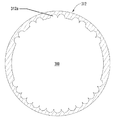
도 5는 본 발명의 여러 예에 따라 사용될 수 있는 예시적인 호젤 링의 사시도이다.
도 6a는 본 발명의 여러 예에 따른 예시적인 조립된 골프 클럽 헤드/샤프트 연결 시스템의 사시도이다.
도 6b는 본 발명의 여러 예에 따른 예시적인 조립된 골프 클럽 헤드/샤프트 연결 시스템의 절단도이다.
도 7a 및 도 7b는 본 발명의 여러 예에 따라 사용될 수 있는 또 다른 예시적인 샤프트 어댑터의 여러 도면을 도시하는 도면이다.
도 8a 및 도 8b는 본 발명의 여러 예에 따라 사용될 수 있는 또 다른 예시적인 호젤 어댑터의 여러 도면을 도시하는 도면이다.
도 9는 본 발명의 여러 예에 따라 사용될 수 있는 또 다른 예시적인 호젤 링의 사시도이다.
도 10은 본 발명의 여러 예에 따른 또 다른 예시적인 조립된 골프 클럽 헤드/샤프트 연결 시스템을 도시하는 도면이다.
도 11은 본 발명의 여러 예에 따른 또 다른 예시적인 조립된 골프 클럽 헤드/샤프트 연결 시스템을 도시하는 도면이다.
도 11b는 본 발명의 여러 예에 따른 또 다른 예시적인 조립된 골프 클럽 헤드/샤프트 연결 시스템의 절단도이다.
도 12는 발명의 여러 예에 따른 골프 클럽 헤드의 사시도이다.
도 13a 및 도 13b는 발명의 여러 예에 따른 골프 클럽 헤드/샤프트 연결 시스템 상의 또 다른 위치 표시기의 사시도 및 확대도를 도시하는 도면이다.
도 14a 및 도 14b는 발명의 여러 예에 따른 골프 클럽 헤드/샤프트 연결 시스템 상의 또 다른 위치 표시기의 사시도 및 확대도이다.
도 15는 발명의 여러 예에 따른 골프 클럽 헤드/샤프트 연결 시스템 상의 또 다른 위치 표시기의 확대도이다.
도 16은 발명의 여러 예에 따른 골프 클럽 헤드/샤프트 연결 시스템 상의 또 다른 위치 표시기의 사시도 및 확대도이다.
도 17a는 발명의 여러 예에 따른 골프 클럽 헤드/샤프트 연결 시스템의 예시적인 호젤 어댑터의 횡단면도이다.
도 17b는 발명의 여러 예에 따른 골프 클럽 헤드/샤프트 연결 시스템의 예시적인 샤프트 어댑터의 횡단면도이다.
도 18a 내지 도 18e는 도 17a의 예시적인 호젤 어댑터와 결합된 도 17b의 예시적인 샤프트 어댑터의 본 발명의 여러 예에 따른 각기 다른 회전 형태들을 횡단면도이다.
도 19a 내지 도 19e는 도 18a 내지 도 18e의 각기 다른 회전 형태와 관련된 본 발명의 여러 예에 따른 다양한 클럽 헤드 구성을 도시하는 도면이다.
도 20a는 발명의 여러 예에 따른 골프 클럽 헤드/샤프트 연결 시스템의 예시적인 호젤 어댑터의 횡단면도이다.
도 20b는 발명의 여러 예에 따른 골프 클럽 헤드/샤프트 연결 시스템의 예시적인 호젤 링의 횡단면도이다.
도 21a 내지 도 21c는 도 20b의 예시적인 호젤 링과 결합된 도 20a의 예시적인 호젤 어댑터의 본 발명의 여러 예에 따른 각기 다른 회전 형태들의 횡단면도이다.
도 22a 내지 도 22c는 도 21a 내지 도 21c의 각기 다른 회전 형태와 관련된 본 발명의 여러 예에 따른 다양한 클럽 헤드 구성을 도시하는 도면이다.
도 23은 본 발명의 여러 예에 따른 각기 다른 클럽 헤드 구성들 각각에 대한 해제 가능한 연결 및 회전 형태의 단면도를 종합적인 요약 차트로 도시하는 도면이다.
도 24a는 본 발명의 여러 예에 따른 예시적인 회전 형태를 위한 해제 가능한 연결부의 단면도이다.
도 24b는 본 발명의 여러 예에 따른 예시적인 회전 형태를 위한 클럽 헤드의 예시적인 페이스각을 도시하는 도면이다.
도 24c는 본 발명의 여러 예에 따른 예시적인 회전 형태를 위한 클럽 헤드의 예시적인 로프트각을 도시하는 도면이다.
도 25a는 본 발명의 여러 예에 따른 예시적인 회전 형태를 위한 해제 가능한 연결부의 단면도이다.
도 25b는 본 발명의 여러 예에 따른 예시적인 회전 형태를 위한 클럽 헤드의 예시적인 페이스각을 도시하는 도면이다.
도 25c는 본 발명의 여러 예에 따른 예시적인 회전 형태를 위한 클럽 헤드의 예시적인 로프트각을 도시하는 도면이다.
도 26a는 본 발명의 여러 예에 따른 예시적인 회전 형태를 위한 해제 가능한 연결부의 단면도이다.
도 26b는 본 발명의 여러 예에 따른 예시적인 회전 형태를 위한 클럽 헤드의 예시적인 페이스각을 도시하는 도면이다.
도 26c는 본 발명의 여러 예에 따른 예시적인 회전 형태를 위한 클럽 헤드의 예시적인 로프트각을 도시하는 도면이다.
도 27a는 본 발명의 여러 예에 따른 예시적인 회전 형태를 위한 해제 가능한 연결부의 단면도이다.
도 27b는 본 발명의 여러 예에 따른 예시적인 회전 형태를 위한 클럽 헤드의 예시적인 페이스각을 도시하는 도면이다.
도 27c는 본 발명의 여러 예에 따른 예시적인 회전 형태를 위한 클럽 헤드의 예시적인 로프트각을 도시하는 도면이다.
도 28a는 본 발명의 여러 예에 따른 예시적인 회전 형태를 위한 해제 가능한 연결부의 단면도이다.
도 28b는 본 발명의 여러 예에 따른 예시적인 회전 형태를 위한 클럽 헤드의 예시적인 페이스각을 도시하는 도면이다.
도 28c는 본 발명의 여러 예에 따른 예시적인 회전 형태를 위한 클럽 헤드의 예시적인 로프트각을 도시하는 도면이다.
도 29a는 본 발명의 여러 예에 따른 예시적인 회전 형태를 위한 해제 가능한 연결부의 단면도이다.
도 29b는 본 발명의 여러 예에 따른 예시적인 회전 형태를 위한 클럽 헤드의 예시적인 페이스각을 도시하는 도면이다.
도 29c는 본 발명의 여러 예에 따른 예시적인 회전 형태를 위한 클럽 헤드의 예시적인 로프트각을 도시하는 도면이다.
도 30a는 본 발명의 여러 예에 따른 예시적인 회전 형태를 위한 해제 가능한 연결부의 단면도이다.
도 30b는 본 발명의 여러 예에 따른 예시적인 회전 형태를 위한 클럽 헤드의 예시적인 페이스각을 도시하는 도면이다.
도 30c는 본 발명의 여러 예에 따른 예시적인 회전 형태를 위한 클럽 헤드의 예시적인 로프트각을 도시하는 도면이다.
도 31a는 본 발명의 여러 예에 따른 예시적인 회전 형태를 위한 해제 가능한 연결부의 단면도이다.
도 31b는 본 발명의 여러 예에 따른 예시적인 회전 형태를 위한 클럽 헤드의 예시적인 페이스각을 도시하는 도면이다.
도 31c는 본 발명의 여러 예에 따른 예시적인 회전 형태를 위한 클럽 헤드의 예시적인 로프트각을 도시하는 도면이다.
도 32a는 본 발명의 여러 예에 따른 예시적인 회전 형태를 위한 해제 가능한 연결부의 단면도이다.
도 32b는 본 발명의 여러 예에 따른 예시적인 회전 형태를 위한 클럽 헤드의 예시적인 페이스각을 도시하는 도면이다.
도 32c는 본 발명의 여러 예에 따른 예시적인 회전 형태를 위한 클럽 헤드의 예시적인 로프트각을 도시하는 도면이다.
도 33a는 본 발명의 여러 예에 따른 예시적인 회전 형태를 위한 해제 가능한 연결부의 단면도이다.
도 33b는 본 발명의 여러 예에 따른 예시적인 회전 형태를 위한 클럽 헤드의 예시적인 페이스각을 도시하는 도면이다.
도 33c는 본 발명의 여러 예에 따른 예시적인 회전 형태를 위한 클럽 헤드의 예시적인 로프트각을 도시하는 도면이다.
도 34a는 본 발명의 여러 예에 따른 예시적인 회전 형태를 위한 해제 가능한 연결부의 단면도이다.
도 34b는 본 발명의 여러 예에 따른 예시적인 회전 형태를 위한 클럽 헤드의 예시적인 페이스각을 도시하는 도면이다.
도 34c는 본 발명의 여러 예에 따른 예시적인 회전 형태를 위한 클럽 헤드의 예시적인 로프트각을 도시하는 도면이다.
도 35a는 본 발명의 여러 예에 따른 예시적인 회전 형태를 위한 해제 가능한 연결부의 단면도이다.
도 35b는 본 발명의 여러 예에 따른 예시적인 회전 형태를 위한 클럽 헤드의 예시적인 페이스각을 도시하는 도면이다.
도 35c는 본 발명의 여러 예에 따른 예시적인 회전 형태를 위한 클럽 헤드의 예시적인 로프트각을 도시하는 도면이다.
도 36a는 본 발명의 여러 예에 따른 예시적인 회전 형태를 위한 해제 가능한 연결부의 단면도이다.
도 36b는 본 발명의 여러 예에 따른 예시적인 회전 형태를 위한 클럽 헤드의 예시적인 페이스각을 도시하는 도면이다.
도 36c는 본 발명의 여러 예에 따른 예시적인 회전 형태를 위한 클럽 헤드의 예시적인 로프트각을 도시하는 도면이다.
도 37a는 본 발명의 여러 예에 따른 예시적인 회전 형태를 위한 해제 가능한 연결부의 단면도이다.
도 37b는 본 발명의 여러 예에 따른 예시적인 회전 형태를 위한 클럽 헤드의 예시적인 페이스각을 도시하는 도면이다.
도 37c는 본 발명의 여러 예에 따른 예시적인 회전 형태를 위한 클럽 헤드의 예시적인 로프트각을 도시하는 도면이다.
도 38a는 본 발명의 여러 예에 따른 예시적인 회전 형태를 위한 해제 가능한 연결부의 단면도이다.
도 38b는 본 발명의 여러 예에 따른 예시적인 회전 형태를 위한 클럽 헤드의 예시적인 페이스각을 도시하는 도면이다.
도 38c는 본 발명의 여러 예에 따른 예시적인 회전 형태를 위한 클럽 헤드의 예시적인 로프트각을 도시하는 도면이다.
도 39a 내지 도 44는 본 발명의 여러 예에 따른 해제 가능한 연결부의 추가적인 실시예를 도시하는 도면이다.
도 45는 본 발명의 여러 예에 따른 골프 클럽 샤프트 및 그립의 일부의 사시도이다. 1 is a diagram generally illustrating a perspective view of an exemplary golf club according to the present invention.
Figure 2 is an enlarged view of an exemplary golf club head / shaft connection system in accordance with an example of the present invention.
Figures 3a and 3b are views showing various views of an exemplary shaft adapter that may be used in accordance with various examples of the present invention.
Figure 4 is a perspective view of an exemplary hosel adapter that may be used in accordance with various examples of the present invention.
Figure 5 is a perspective view of an exemplary hosel ring that may be used in accordance with various examples of the present invention.
6A is a perspective view of an exemplary assembled golf club head / shaft connection system in accordance with various examples of the present invention.
6B is a cutaway view of an exemplary assembled golf club head / shaft connection system in accordance with various examples of the present invention.
Figures 7A and 7B are views showing various views of yet another exemplary shaft adapter that may be used in accordance with various examples of the present invention.
8A and 8B are views showing various views of another exemplary hosel adapter that may be used in accordance with various examples of the present invention.
9 is a perspective view of another exemplary hosel ring that may be used in accordance with various examples of the present invention.
10 is a diagram illustrating another exemplary assembled golf club head / shaft connection system in accordance with various examples of the present invention.
11 is a diagram illustrating another exemplary assembled golf club head / shaft connection system in accordance with various examples of the present invention.
11B is a cutaway view of another exemplary assembled golf club head / shaft connection system in accordance with various examples of the present invention.
Figure 12 is a perspective view of a golf club head according to various embodiments of the invention.
13A and 13B are a perspective view and an enlarged view of another position indicator on a golf club head / shaft connection system according to various examples of the invention.
14A and 14B are perspective and enlarged views of another position indicator on a golf club head / shaft connection system according to various examples of the invention.
15 is an enlarged view of another position indicator on a golf club head / shaft connection system according to various examples of the invention.
16 is a perspective view and an enlarged view of another position indicator on a golf club head / shaft connection system according to various examples of the invention.
17A is a cross-sectional view of an exemplary hosel adapter of a golf club head / shaft connection system in accordance with various embodiments of the invention.
Figure 17B is a cross-sectional view of an exemplary shaft adapter of a golf club head / shaft connection system in accordance with various embodiments of the invention.
Figs. 18A-E are cross-sectional views of different rotational configurations according to various embodiments of the present invention of the exemplary shaft adapter of Fig. 17B combined with the exemplary hosel adapter of Fig. 17A.
Figs. 19A-19E illustrate various club head configurations in accordance with various examples of the present invention associated with the different rotational configurations of Figs. 18A-18E.
20A is a cross-sectional view of an exemplary hosel adapter of a golf club head / shaft connection system in accordance with various embodiments of the invention.
20B is a cross-sectional view of an exemplary hosel ring of a golf club head / shaft connection system in accordance with various embodiments of the invention.
Figs. 21A-21C are cross-sectional views of different rotational configurations according to various examples of the present invention of the exemplary hosel adapter of Fig. 20A combined with the exemplary hosel ring of Fig.
Figures 22A-22C illustrate various club head configurations in accordance with various examples of the present invention associated with the different rotational configurations of Figures 21A-21C.
Figure 23 is a schematic summary chart of cross-sectional views of releasable connections and forms of rotation for each of the different club head configurations in accordance with various examples of the present invention.
24A is a cross-sectional view of a releasable connection for an exemplary rotation configuration in accordance with various examples of the present invention.
FIG. 24B is a diagram illustrating an exemplary face angle of a club head for an exemplary rotation form in accordance with various examples of the present invention. FIG.
24C is a diagram illustrating an exemplary loft angle of a club head for an exemplary rotation configuration in accordance with various examples of the present invention.
25A is a cross-sectional view of a releasable connection for an exemplary rotation configuration in accordance with various examples of the present invention.
FIG. 25B is a diagram illustrating exemplary face angles of a club head for an exemplary rotation configuration in accordance with various examples of the present invention. FIG.
25C is a diagram illustrating an exemplary loft angle of a club head for an exemplary rotation configuration in accordance with various examples of the present invention.
26A is a cross-sectional view of a releasable connection for an exemplary rotation configuration in accordance with various examples of the present invention.
26B is a diagram illustrating exemplary face angles of a club head for an exemplary rotation configuration in accordance with various examples of the present invention.
26C is a diagram illustrating an exemplary loft angle of a club head for an exemplary rotation configuration in accordance with various examples of the present invention.
Figure 27A is a cross-sectional view of a releasable connection for an exemplary rotation configuration in accordance with various examples of the present invention.
27B is a diagram illustrating an exemplary face angle of a club head for an exemplary rotation configuration in accordance with various examples of the present invention.
Figure 27c is a diagram illustrating an exemplary loft angle of a club head for an exemplary rotation configuration in accordance with various examples of the present invention.
28A is a cross-sectional view of a releasable connection for an exemplary rotation configuration in accordance with various examples of the present invention.
FIG. 28B is a diagram illustrating exemplary face angles of a club head for an exemplary rotation configuration in accordance with various examples of the present invention. FIG.
28C is a diagram illustrating an exemplary loft angle of a club head for an exemplary rotation configuration in accordance with various examples of the present invention.
29A is a cross-sectional view of a releasable connection for an exemplary rotation configuration in accordance with various examples of the present invention.
29B is a diagram illustrating exemplary face angles of a club head for an exemplary rotational configuration in accordance with various examples of the present invention.
29C is a diagram illustrating an exemplary loft angle of a club head for an exemplary rotation configuration in accordance with various examples of the present invention.
30A is a cross-sectional view of a releasable connection for an exemplary rotation configuration in accordance with various examples of the present invention.
30B is a diagram illustrating exemplary face angles of a club head for an exemplary rotation configuration in accordance with various examples of the present invention.
30C is a diagram illustrating an exemplary loft angle of a club head for an exemplary rotation configuration in accordance with various examples of the present invention.
31A is a cross-sectional view of a releasable connection for an exemplary rotation configuration in accordance with various examples of the present invention.
FIG. 31B is a diagram illustrating exemplary face angles of a club head for an exemplary rotation form in accordance with various examples of the present invention.
31C is a diagram illustrating an exemplary loft angle of a club head for an exemplary rotation configuration in accordance with various examples of the present invention.
32A is a cross-sectional view of a releasable connection for an exemplary rotation configuration according to various examples of the present invention.
32B is a diagram illustrating an exemplary face angle of a club head for an exemplary rotational configuration according to various examples of the present invention.
32C is a diagram illustrating an exemplary loft angle of a club head for an exemplary rotation configuration in accordance with various examples of the present invention.
33A is a cross-sectional view of a releasable connection for an exemplary rotation configuration in accordance with various examples of the present invention.
Figure 33B is a diagram illustrating an exemplary face angle of a club head for an exemplary rotation configuration in accordance with various examples of the present invention.
33C is a diagram illustrating an exemplary loft angle of a club head for an exemplary rotational configuration in accordance with various examples of the present invention.
34A is a cross-sectional view of a releasable connection for an exemplary rotation configuration according to various examples of the present invention.
Figure 34B is a diagram illustrating an exemplary face angle of a club head for an exemplary rotation configuration in accordance with various examples of the present invention.
34C is a diagram illustrating an exemplary loft angle of a club head for an exemplary rotation configuration in accordance with various examples of the present invention.
35A is a cross-sectional view of a releasable connection for an exemplary rotation configuration in accordance with various examples of the present invention.
35B is a diagram illustrating an exemplary face angle of a club head for an exemplary rotation configuration in accordance with various examples of the present invention.
35C is a diagram illustrating an exemplary loft angle of a club head for an exemplary rotation configuration in accordance with various examples of the present invention.
36A is a cross-sectional view of a releasable connection for an exemplary rotation configuration in accordance with various examples of the present invention.
FIG. 36B is a diagram illustrating an exemplary face angle of a club head for an exemplary rotational configuration in accordance with various examples of the present invention.
Figure 36c is a diagram illustrating an exemplary loft angle of a club head for an exemplary rotation configuration in accordance with various examples of the present invention.
37A is a cross-sectional view of a releasable connection for an exemplary rotation configuration in accordance with various examples of the present invention.
37B is a diagram illustrating an exemplary face angle of a club head for an exemplary rotation configuration in accordance with various examples of the present invention.
37C is a diagram illustrating an exemplary loft angle of a club head for an exemplary rotation configuration in accordance with various examples of the present invention.
38A is a cross-sectional view of a releasable connection for an exemplary rotation configuration according to various examples of the present invention.
38B is a diagram illustrating an exemplary face angle of a club head for an exemplary rotation configuration in accordance with various examples of the present invention.
Figure 38c is a diagram illustrating an exemplary loft angle of a club head for an exemplary rotation configuration in accordance with various examples of the present invention.
Figures 39A-44 illustrate further embodiments of releasable connections according to various examples of the present invention.
45 is a perspective view of a portion of a golf club shaft and grip according to various examples of the present invention.
다음과 같은 첨부된 도면을 고려하면서 아래의 상세한 설명을 참조함으로써 본 발명과 본 발명의 특정의 이점들에 대해 보다 완전하게 이해할 수 있게 될 것이다.BRIEF DESCRIPTION OF THE DRAWINGS The present invention will become more fully understood from the detailed description and the accompanying drawings, wherein: FIG.
본 명세서를 읽는 자들은 첨부된 도면이 반드시 축척에 맞게 도시된 것이 아니라는 점을 알고 있어야 한다.It is to be understood by those skilled in the art that the accompanying drawings are not necessarily drawn to scale.
본 발명에 따른 다양한 예시적 구조에 대한 다음의 설명에서는, 명세서의 일부를 형성하며 본 발명에 따른 다양한 예시적인 연결 조립체들과, 골프 클럽 헤드들과, 골프 클럽 구조들을 예시의 목적으로 도시하고 있는 첨부 도면을 참조한다. 추가적으로, 부품 및 구조의 그 밖의 다른 특정 배치가 이용될 수 있으며, 본 발명의 범위를 벗어나지 않으면서 구조적 및 기능적 변경도 가해질 수 있다는 것을 이해하여야 한다. 또한, 용어 "상부(top)", "바닥(bottom)", "정면(front)", "배면(back)", "후방(rear)", "측면(side)", "하측(underside)", "상측(overhead)" 등이 본 발명의 다양한 예시적 특징 및 요소를 설명하기 위해 명세서에서 사용될 수 있지만, 이 용어들은 예를 들어 도면에 도시된 예시적 배치 방향 및/또는 전형적인 사용 시의 배치 방향에 기초하여 본 명세서에서 편의상 사용된다. 본 명세서 내의 그 어느 것도 본 발명의 범위 내에 속하게 하기 위하여 구조의 특정된 3차원 또는 공간적 배치 방향을 요구하는 것으로 해석되어서는 안 된다.In the following description of various exemplary structures according to the present invention, there are shown various exemplary coupling assemblies, golf club heads, and golf club structures in accordance with the invention forming part of the specification for purposes of illustration Please refer to the attached drawings. In addition, it should be understood that other specific arrangements of parts and structures may be utilized, and structural and functional changes may be made without departing from the scope of the present invention. The terms "top," " bottom, "" front," " back, "" rear," " side, "&Quot;, "overhead ", and the like, may be used in the specification to describe various exemplary features and elements of the present invention, although they may be used, for example, in the exemplary deployment directions shown in the figures and / Is used herein for convenience in reference to the placement direction. Nothing in this specification should be construed as requiring a specified three-dimensional or spatial orientation of the structure to be within the scope of the present invention.
A. 본 발명의 여러 예에 따른, 골프 클럽 헤드/샤프트 연결 조립체 및 그 조립체를 포함하는 골프 클럽에 대한 일반적인 설명 A. A general description of a golf club head / shaft connecting assembly and a golf club comprising the assembly, according to various examples of the present invention.
일반적으로, 위에서 설명한 바와 같이, 본 발명의 여러 양태들은 클럽 헤드와 샤프트를 손쉽게 교환하고 그리고/또는 서로에 대해 손쉽게 재위치시킬 수 있도록 하는 해제 가능한 방식으로 골프 클럽 헤드를 샤프트에 연결하기 위한 시스템 및 방법에 관한 것이다. 본 발명의 여러 양태들에 대한 더 상세한 설명을 아래에서 한다.In general, as described above, various aspects of the present invention provide a system for connecting a golf club head to a shaft in a releasable manner that allows for easy exchange and / or easy repositioning of the club head and shaft, and ≪ / RTI > A more detailed description of various aspects of the present invention follows.
1. 본 발명에 따른 예시적인 골프 클럽 헤드/샤프트 연결 조립체 및 골프 클럽 구조 1. Exemplary golf club head / shaft connection assembly and golf club structure according to the present invention
본 발명의 한 가지 양태는 골프 클럽 헤드와 샤프트를 견고하지만 해제 가능하게 연결하기 위한 골프 클럽 헤드/샤프트 연결 조립체에 관한 것이다. 이러한 조립체는, 예를 들어, (a) 제1 단부 및 대향하는 제2 단부를 갖는 대체로 원통형 형상인 샤프트 어댑터로서, 상기 제1 단부는 골프 클럽 샤프트를 수용하는 원통형 내부 챔버로 접근할 수 있게 하는 제2 개구를 포함하고, 원통형 구조의 외부면(예, 선택적으로는 상기 제2 단부보다는 상기 제1 단부에 더 가까움)은 제1 회전 억제 구조체를 포함하고, 상기 제2 단부는 고정 구조체를 포함하는 구성으로 된, 샤프트 어댑터; (b) 대체로 원통형 형상인 호젤 어댑터로서, 당해 호젤 어댑터의 제1 단부의 내부 보어는 상기 제1 회전 억제 구조체와 결합되는 제2 회전 억제 구조체를 포함하고, 당해 호젤 어댑터의 제2 단부는 고정 부재를 수용하는 제3 개구를 포함하며, 당해 호젤 어댑터의 외부면은 제3 회전 억제 구조체를 포함하는 구성으로 된, 호젤 어댑터; (c) 대체로 원통형 형상인 호젤 링으로서, 당해 호젤 링의 내부 보어는 상기 제3 회전 억제 구조체와 결합되는 제4 회전 억제 구조체를 포함하는 구성으로 된, 호젤 링; 및 (d) 고정 구조체를 해제 가능하게 결합시키는 고정 시스템을 포함한다. 본 발명에 따른 몇몇 예시적인 구조에서, 다양하게 다른 고정 구조체들과 고정 시스템들이 본 발명에서 벗어남이 없이 사용될 수 있는데, 그와 같은 고정 구조체는 샤프트 어댑터의 제2 단부에 형성되는 나사 구멍을 포함할 것이고, 또한 그와 같은 고정 시스템은 상기 나사 구멍에 맞물리는 나사 볼트 요소를 포함할 것이다.One aspect of the invention relates to a golf club head / shaft connection assembly for rigid but releasably coupling a golf club head and shaft. (A) a generally cylindrical shaft adapter having a first end and an opposing second end, the first end being accessible to a cylindrical inner chamber housing a golf club shaft (E.g., closer to the first end than the second end) of the cylindrical structure includes a first antirotational structure and the second end comprises a fixed structure A shaft adapter; (b) a generally cylindrical shaped hosel adapter, the inner bore of the first end of the hosel adapter including a second anti-rotation structure coupled with the first anti-rotation structure, A hosel adapter having a configuration comprising an outer surface of the hosel adapter including a third anti-rotation structure; (c) a hosel ring having a generally cylindrical shape, wherein the inner bore of the hosel ring includes a fourth rotation restraining structure joined to the third rotation restraining structure; And (d) a fastening system releasably coupling the fastening structure. In some exemplary constructions according to the present invention, a variety of different anchoring structures and anchoring systems may be used without departing from the invention, such an anchoring structure including a threaded hole formed in the second end of the shaft adapter And such a fastening system would also include a threaded bolt element that engages the threaded hole.
다양한 회전 억제 구조체들 및 시스템들이 본 발명에서 벗어남이 없이 사용될 수 있다. 본 발명에 따른 몇몇 예시적인 구조에서, 회전 억제 구조체는 스플라인 및/또는 치형 부재를 포함할 수 있다.Various anti-rotation structures and systems may be used without departing from the invention. In some exemplary constructions according to the present invention, the anti-rotation structure may comprise a spline and / or a toothed member.
샤프트 어댑터의 외부면과 샤프트 어댑터의 원통형 내부 챔버는 동축으로 구성할 수 있다. 한편, 이러한 원통형 구조들은 동축일 필요는 없다(예, 원통형 구조들은 각기 다른 방향으로 연장될 수 있고, 평행하게 연장될 수 있고, 동축이 아닌 방향으로 연장될 수 있는 등등으로 구성될 수 있다). 클럽 헤드 타격면에 대한 샤프트의 여러 가지 특성, 위치, 각도 등은, 아래에서 상세하게 설명하는 바와 같이, 동축이 아닌 원통형 내부와 외부면을 제공함으로써(또는 클럽 헤드, 샤프트 등의 그 밖의 다른 특징부를 통해서) 변경될 수 있다. 원하는 경우, 샤프트 어댑터(예, 샤프트 어댑터의 제1 단부)의 외부면에, 사용 시에 사용자가 클럽 헤드에 대한 샤프트/클럽 헤드 연결 부재의 위치를 쉽게 파악할 수 있도록 하는 회전 위치 표시기가 포함될 수 있다.The outer surface of the shaft adapter and the cylindrical inner chamber of the shaft adapter may be coaxial. On the other hand, these cylindrical structures need not be coaxial (e.g., the cylindrical structures may extend in different directions, extend in parallel, extend in non-coaxial directions, etc.). The various characteristics, positions, angles, etc. of the shaft relative to the club head striking surface may be determined by providing a non-coaxial cylindrical inner and outer surfaces (or other features such as club heads, shafts, etc.) Through the Department). If desired, a rotational position indicator may be included on the outer surface of the shaft adapter (e.g., the first end of the shaft adapter) to enable the user to easily grasp the position of the shaft / club head connecting member relative to the club head in use .
또한, 호젤 어댑터의 외부면과 호젤 어댑터의 내부 보어를 동축으로 구성할 수 있다. 한편, 이러한 원통형 구조들은 동축일 필요는 없다(예, 원통형 구조들은 각기 다른 방향으로 연장될 수 있고, 평행하게 연장될 수 있고, 동축이 아니 방향으로 연장될 수 있는 등등으로 구성될 수 있다). 클럽 헤드 타격면에 대한 샤프트의 여러 가지 특성, 위치, 각도 등은, 아래에서 상세하게 설명하는 바와 같이, 동축이 아닌 내부 보어와 외부면을 제공함으로써(또는 클럽 헤드, 샤프트 등의 그 밖의 다른 특징부를 통해서) 변경될 수 있다. 원하는 경우, 호젤 어댑터(예, 호젤 어댑터의 제1 단부)의 외부면에, 사용 시에 사용자가 클럽 헤드에 대한 샤프트/클럽 헤드 연결 부재의 위치를 쉽게 파악할 수 있도록 하는 회전 위치 표시기가 포함될 수 있다.In addition, the outer surface of the hosel adapter and the inner bore of the hosel adapter can be coaxially configured. On the other hand, these cylindrical structures need not be coaxial (e.g., cylindrical structures may extend in different directions, extend in parallel, be coaxial, extend in a direction, etc.). Various features, positions, angles, etc., of the shaft relative to the club head striking surface may be achieved by providing non-coaxial internal bores and external surfaces (or other features such as club heads, shafts, etc.) Through the Department). If desired, a rotational position indicator may be included on the outer surface of the hosel adapter (e.g., the first end of the hosel adapter) to enable the user to easily grasp the position of the shaft / club head connection member relative to the club head in use .
본 발명의 양태는 또한 위에서 설명한 유형의 샤프트/클럽 헤드 연결 조립체를 사용하여 샤프트를 골프 클럽에 결합시킨 골프 클럽에도 관한 것이다. 이러한 골프 클럽은, (a) 고정 부재를 수용하는 제1 개구를 포함하는 클럽 헤드 챔버를 구비하는 골프 클럽 헤드; (b) 상기 클럽 헤드 챔버 내에 고정된, 대체로 원통형 형상인 호젤 링으로서, 당해 호젤 링의 내부 보어가 제4 회전 억제 구조체를 포함하는 구성으로 된, 호젤 링; (c) 제1 단부 및 대향하는 제2 단부를 갖는 대체로 원통형 형상인 샤프트 어댑터로서, 당해 샤프트 어댑터의 제1 단부는 골프 클럽 샤프트를 수용하는 원통형 내부 챔버를 형성하는 제2 개구를 포함하고, 당해 샤프트 어댑터의 외부면은 제1 회전 억제 구조체를 포함하고, 제2 단부는 고정 구조체를 포함하는 구성으로 된, 샤프트 어댑터; (d) 상기 골프 클럽 헤드의 클럽 헤드 챔버 안으로 연장되는, 대체로 원통형 형상인 호젤 어댑터로서, 당해 호젤 어댑터의 제1 단부는 상기 제1 회전 억제 구조체와 결합되는 제2 회전 억제 구조체를 포함하고, 당해 호젤 어댑터의 제2 단부는 고정 부재를 수용하는 제3 개구를 포함하며, 또한 당해 호젤 어댑터의 외부면은 상기 호젤 링의 제4 회전 억제 구조체와 결합되는 제3 회전 억제 구조체를 포함하는 구성으로 된, 호젤 어댑터; (e) 상기 샤프트 어댑터의 원통형 내부 챔버 안에 결합되는 샤프트; (f) 상기 골프 클럽 헤드의 클럽 헤드 챔버 안으로 연장되며, 샤프트 연결 부재를 골프 클럽 헤드에 해제 가능하게 결합시킬 수 있도록 샤프트 어댑터의 고정 구조체를 해제 가능하게 결합시키는 고정 부재; 및/또는 (g) 샤프트의 자유 단부와 결합되는 그립 부재를 포함할 수 있다. 고정 부재는 클럽 헤드의 솔(sole)에 마련된 개구를 통해 클럽 헤드의 클럽 헤드 챔버 안에 삽입될 수 있다.Aspects of the present invention also relate to golf clubs in which a shaft is coupled to a golf club using a shaft / club head connecting assembly of the type described above. The golf club includes: (a) a golf club head having a club head chamber including a first opening for receiving a holding member; (b) a hosel ring having a generally cylindrical configuration fixed within the club head chamber, the hosel ring having a configuration in which the inner bore of the hosel ring includes a fourth anti-rotation structure; (c) a generally cylindrical shaped shaft adapter having a first end and an opposing second end, the first end of the shaft adapter including a second opening defining a cylindrical inner chamber for receiving a golf club shaft, The outer surface of the shaft adapter comprising a first antirotational structure and the second end comprises a fastening structure; (d) a generally cylindrical shaped hosel adapter extending into the club head chamber of the golf club head, the first end of the hosel adapter including a second anti-rotation structure coupled with the first anti-rotation structure, Wherein the second end of the hosel adapter includes a third aperture for receiving a fixation member and the outer surface of the hosel adapter is coupled to a fourth rotation inhibition structure of the hosel ring , Hosel adapter; (e) a shaft coupled into the cylindrical inner chamber of the shaft adapter; (f) a securing member extending into the club head chamber of the golf club head and releasably engaging the securing structure of the shaft adapter to releasably engage the shaft connecting member with the golf club head; And / or (g) a grip member engaged with the free end of the shaft. The fixing member may be inserted into the club head chamber of the club head through an opening provided in the sole of the club head.
2. 본 발명에 따른 골프 클럽 헤드/샤프트 연결 조립체 및 이 조립체를 포함하는 골프 클럽을 제조 및 사용하는 예시적 방법 2. An exemplary method of making and using a golf club head / shaft connecting assembly and a golf club comprising the assembly according to the present invention
본 발명의 또 다른 양태는 본 발명의 여러 예에 따라 샤프트/클럽 헤드 연결 조립체(예, 위에서 설명한 유형의 것)를 제조하는 방법에 관한 것이다. 이러한 방법은, 예를 들어, (a) 제1 단부 및 대향하는 제2 단부를 갖는 원통형 형상인 샤프트 어댑터를 제조하고(예, 주조 또는 성형 공정을 통해서, 사출 성형을 통해서, 등등); (b) 상기 샤프트 어댑터의 제1 단부에서 골프 클럽 샤프트를 수용하는 원통형 내부 챔버를 제조하고(예, 드릴링 또는 기계 가공 공정을 통해서, 주조 또는 성형 공정을 통해서, 등등); (c) 회전 억제 구조체를, 예를 들어 상기 제2 단부보다는 상기 제1 단부에 더 가깝게 해서, 샤프트 어댑터의 외부면의 일부로서 형성하고(예, 연삭, 기계 가공, 성형, 주조 등에 의해); (d) 상기 샤프트 어댑터의 제2 단부에 고정 구조체를 형성하고(예, 주조, 성형, 드릴링, 탭핑, 또는 기계 가공 공정 등에 의해); (e) 제1 단부 및 대향하는 제2 단부를 갖는 원통형 형상인 호젤 어댑터를 제조하고(예, 주조 또는 성형 공정을 통해서, 사출 성형을 통해서, 등등); (f) 상기 제1 회전 억제 구조체와 결합되는 제2 회전 억제 구조체를 호젤 어댑터의 제1 단부의 일부로서 형성하고(예, 연삭, 기계 가공, 성형, 주조 등에 의해); (g) 대체로 원통형 형상이며 클럽 헤드 챔버 내에 고정되는 호젤 링을 제조하고; (h) 호젤 링의 내부 보어의 일부인 제4 회전 억제 구조체와 결합되는 제3 회전 억제 구조체를 호젤 어댑터의 외부면의 일부로서 형성하고(예, 연삭, 기계 가공, 성형, 주조 등에 의해); (i) 고정 구조체에 결합시키기 위한 고정 부재를 마련하는(예, 제조하는 것, 제3의 공급자로부터 공급받는 것 등등에 의해) 것을 포함한다. 원하는 경우, 고정 구조체는 샤프트 어댑터의 제2 단부에 형성되는 나사 구멍으로서 형성될 수 있고, 고정 부재는 상기 나사 구멍에 맞물릴 수 있는 나사 볼트 요소로서 형성될 수 있다. 상기 조립체는 위에서 설명한(그리고 아래에서 더 상세하게 설명하는) 것과 같은 여러 가지 구조 및/또는 구성들 중 임의의 것을 포함할 수 있다.Another aspect of the present invention is directed to a method of manufacturing a shaft / club head connecting assembly (e.g., of the type described above) in accordance with several examples of the present invention. Such a method may include, for example, (a) fabricating a shaft adapter in a cylindrical shape having a first end and an opposite second end (e.g., through a casting or molding process, through injection molding, etc.); (b) manufacturing a cylindrical inner chamber (e.g., through a drilling or machining process, through a casting or molding process, etc.) that receives a golf club shaft at a first end of the shaft adapter; (c) forming (e.g., grinding, machining, forming, casting, etc.) as part of the outer surface of the shaft adapter, with the anti-rotation structure being closer to the first end than, for example, to the second end; (d) forming (e.g., casting, forming, drilling, tapping, or machining processes, etc.) a securing structure at the second end of the shaft adapter; (e) manufacturing a hosel adapter having a cylindrical shape with a first end and an opposite second end (e.g., through a casting or molding process, through injection molding, etc.); (f) forming (e.g., grinding, machining, forming, casting, etc.) a second anti-rotation structure associated with the first anti-rotation structure as part of the first end of the hosel adapter; (g) fabricating a hosel ring generally cylindrical in shape and secured within the club head chamber; (h) forming (e.g., grinding, machining, forming, casting, etc.) a third anti-rotation structure as part of the outer surface of the hosel adapter, the third anti-rotation structure being in engagement with a fourth anti-rotation structure that is part of the inner bore of the hosel ring; (i) providing (eg, by making, receiving from a third party, etc.) a fixing member for engaging the stationary structure. If desired, the fastening structure may be formed as a threaded hole formed in the second end of the shaft adapter, and the fastening member may be formed as a threaded bolt element engageable with the threaded hole. The assembly may include any of a variety of structures and / or configurations, such as those described above (and described in greater detail below).
본 발명의 또 다른 양태는 본 발명의 여러 예에 따라 샤프트/클럽 헤드 연결 조립체를 사용하여 골프 클럽을 조립하는 방법에 관한 것이다. 이러한 방법은, (a) 고정 부재를 수용하는 제1 개구를 포함하는 클럽 헤드 챔버를 구비하는 골프 클럽 헤드를 마련하고(예, 제조하는 것, 제3의 공급자로부터 공급받는 것 등등에 의해); (b) 상기 클럽 헤드 챔버 내에 고정된, 대체로 원통형 형상인 호젤 링을 제조하고; (c) 호젤 링의 내부 보어의 일부인 제4 회전 억제 구조체와 결합되는 제3 회전 억제 구조체를 호젤 어댑터의 외부면의 일부로서 형성하고(예, 연삭, 기계 가공, 성형, 주조 등에 의해); (d) 제1 단부 및 대향하는 제2 단부를 갖는 원통형 형상인 샤프트 어댑터에 샤프트를 결합시키고(예, 해제 가능한 방식으로, 접합제 또는 접착제에 의해서, 다른 융접 기술에 의해서, 등등); (e) 제2 회전 억제 구조체를 포함하는 제1 단부를 구비하며 제3 개구를 포함하는 제2 단부를 구비하는 호젤 어댑터를 골프 클럽 헤드의 클럽 헤드 챔버 안에 배치하고, 호젤 링 상의 상기 제4 회전 억제 구조체를 회전하지 못하게 결합시키고(예, 회전 억제 구조체를 이용해서, 접합제, 접착제, 다른 융접 기술, 기계적 연결부 등에 의해서); (f) 샤프트 어댑터가 호젤 어댑터 및 골프 클럽 헤드에 대해서 회전하는 것을 방지하기 위해 호젤 어댑터에 마련된 상기 제2 회전 억제 구조체에 제1 회전 억제 구조체가 결합될 수 있도록, 샤프트 어댑터의 적어도 일부를 호젤 어댑터 안에 배치하고; (g) 클럽 헤드 챔버의 제2 단부 안에 고정 부재를 배치하고; (h) 샤프트 어댑터를 골프 클럽 헤드에 해제 가능하게 결합시키기 위해 샤프트 어댑터에 마련된 고정 구조체에 고정 부재를 해제 가능하게 결합시키는 것을 포함한다.Another aspect of the invention relates to a method of assembling a golf club using a shaft / club head connecting assembly in accordance with various examples of the present invention. The method includes (a) providing a golf club head having a club head chamber including a first opening for receiving a fastening member (e.g., by manufacturing, being supplied by a third supplier, etc.); (b) fabricating a generally cylindrical shaped hosel ring secured within the club head chamber; (c) forming (e.g., grinding, machining, forming, casting, etc.) a third anti-rotation structure as part of the outer surface of the hosel adapter, the third anti-rotation structure being in engagement with a fourth anti-rotation structure that is part of the inner bore of the hosel ring; (d) attaching the shaft to a shaft adapter having a cylindrical shape with a first end and an opposing second end (e.g., releasable manner, by a bonding agent or adhesive, by other fusing techniques, etc.); (e) a hosel adapter having a first end comprising a second rotation inhibiting structure and a second end comprising a third opening, is disposed in the club head chamber of the golf club head, and the fourth rotation (E.g., by using a rotatable restraining structure, by bonding agents, adhesives, other fusing techniques, mechanical connections, etc.); (f) at least a portion of the shaft adapter is connected to a hosel adapter, such that the first anti-rotation structure can be coupled to the second anti-rotation structure provided on the hosel adapter to prevent rotation of the shaft adapter relative to the hosel adapter and the golf club head, Placed in; (g) disposing a fixation member within the second end of the club head chamber; (h) releasably engaging the securing member to the securing structure provided on the shaft adapter to releasably engage the shaft adapter with the golf club head.
원하는 경우, 클럽 헤드의 로프트각, 라이각, 페이스각, 오프셋, 인셋(inset), 또는 그 밖의 다른 파라미터들을 변경시킬 수 있도록 하기 위해, 예컨대, 클럽 헤드에 대한 샤프트의 위치를 변경함으로써(예를 들어, 샤프트 어댑터의 챔버를 수용하는 원통형 내부 샤프트가 외부의 원통형 표면에 대해 동축이 아닐 때에는 샤프트와 샤프트 어댑터를 클럽 헤드에 대해 회전시킴으로써), 클럽 헤드의 다양한 특성들 또는 파라미터들을 변경시킬 수 있다. 이러한 방법은, (a) 샤프트 어댑터를 골프 클럽 헤드에 대해서 해제시키거나 분리시키고; (b) 클럽 헤드의 볼 타격면에 대한 샤프트의 자유 단부의 위치를 변경시킬 수 있도록 하기 위해 골프 클럽 헤드에 대한 샤프트의 위치를 변경하고(예, 이들을 서로에 대해 회전시킴으로써 변경하고); (c) 샤프트 어댑터를 상기 변경된 위치에 있는 골프 클럽 헤드에 해제 가능하게 결합시키기 위해 샤프트 어댑터의 고정 구조체에 고정 부재를 해제 가능하게 결합시키는 것을 포함한다.If desired, in order to be able to change the loft angle, lie angle, face angle, offset, inset, or other parameters of the club head, for example, by changing the position of the shaft relative to the club head , By rotating the shaft and shaft adapter relative to the club head when the cylindrical inner shaft that houses the chamber of the shaft adapter is not coaxial to the outer cylindrical surface), the various characteristics or parameters of the club head may be altered. This method comprises: (a) releasing or disengaging the shaft adapter relative to the golf club head; (b) altering the position of the shaft relative to the golf club head (e.g., by rotating them relative to each other) so as to change the position of the free end of the shaft relative to the ball striking surface of the club head; (c) releasably engaging the securing member to the securing structure of the shaft adapter to releasably engage the shaft adapter to the golf club head in the altered position.
호젤 어댑터의 위치는, 예컨대 호젤 어댑터를 클럽 헤드에 대해 회전시킴으로써, 클럽 헤드에 대해 변경시킬 수 있다. 이러한 방법은, (a) 샤프트 어댑터를 호젤 어댑터 및 골프 클럽 헤드에 대해서 해제시키거나 분리시키고; (b) 호젤 어댑터를 골프 클럽 헤드에 대해서 적어도 부분적으로 해제시키거나 분리시키고; (c) 골프 클럽 헤드에 대한 호젤 어댑터의 회전 위치 또는 그 밖의 다른 배치 방향을 변경하고; (d) 샤프트 어댑터가 호젤 어댑터 및 골프 클럽 헤드에 대해서 회전하는 것을 방지하기 위해 샤프트 어댑터에 마련된 회전 억제 구조체에 호젤 어댑터의 회전 억제 구조체가 결합될 수 있도록, 샤프트 어댑터의 적어도 일부를 호젤 어댑터 안에 배치하고; (e) 클럽 헤드 챔버의 제2 단부 안에 고정 부재를 배치하고; (f) 샤프트 어댑터를 호젤 어댑터 및 골프 클럽 헤드에 해제 가능하게 결합시키기 위해 샤프트 어댑터에 마련된 고정 구조체에 고정 부재를 해제 가능하게 결합시키는 것을 포함한다.The position of the hosel adapter can be altered relative to the club head, for example by rotating the hosel adapter against the club head. The method includes: (a) releasing or disengaging the shaft adapter relative to the hosel adapter and the golf club head; (b) at least partially releasing or disengaging the hosel adapter relative to the golf club head; (c) altering the rotational position or other orientation of the hosel adapter relative to the golf club head; (d) at least a portion of the shaft adapter is disposed within the hosel adapter so that the anti-rotation structure of the hosel adapter can be coupled to the anti-rotation structure provided on the shaft adapter to prevent rotation of the shaft adapter relative to the hosel adapter and the golf club head and; (e) disposing a securing member within the second end of the club head chamber; (f) releasably coupling the fastening member to a fastening structure provided on the shaft adapter for releasably coupling the shaft adapter to the hosel adapter and the golf club head.
이하에서는 본 발명의 여러 특정 예들에 대해 설명한다. 명세서를 읽는 자들이 이해하고 있어야 할 점은, 이들 특정 예들은 본 발명의 여러 예를 단지 예시하고자 기재된 것이므로 본 발명을 제한하는 것으로 해석되어서는 안 된다는 점이다.Various specific examples of the present invention will be described below. It is to be understood by those skilled in the art that these specific examples are set forth to illustrate but not limit the scope of the invention.
C. 본 발명의 여러 특정 예C. Various specific examples of the present invention
도 1은 본 발명의 적어도 일부 예에 따른 예시적인 골프 클럽(100)을 일반적으로 도시하고 있다. 이 클럽(100)은 클럽 헤드(102), 클럽 헤드를 샤프트(106)에 연결시키는 해제 가능한 클럽 헤드/샤프트 연결 영역(104)(아래에서 더 상세하게 설명한다), 및 샤프트(106)에 결합되는 그립 부재(108)를 포함한다. 드라이버/우드 타입 골프 클럽 헤드(102)가 도면에 도시되어 있지만, 본 발명의 여러 양태들은, 예를 들어, 페어웨이 우드 클럽 헤드(예, 13도 내지 17도 범위의 로프트각을 갖는 3번 우드, 15도 내지 19도 범위의 로프트각을 갖는 5번 우드); 아이언 타입 골프 클럽 헤드(임의의 원하는 로프트각을 갖는 것으로, 예를 들어, 0번 아이언 또는 1번 아이언에서부터 웨지까지); 우드 또는 아이언 타입 하이브리드 골프 클럽 헤드(임의의 원하는 로프트각, 예를 들어 대체로 15도 내지 25도의 로프트각을 가짐); 퍼터 헤드 등을 포함하는, 어떤 타입의 클럽 헤드에도 적용할 수 있다. 클럽 헤드들은, 당해 기술 분야에서 공지되고 그리고/또는 사용되고 있는 바와 같은 종래의 재료, 종래의 구조, 종래의 방식을 포함한, 임의의 바람직한 재료, 임의의 바람직한 구조 및/또는 임의의 바람직한 방식으로 만들어질 수 있고, 선택적으로는, 클럽 헤드/샤프트 연결 부품을 수용할 수 있도록 변경(필요한 경우, 예컨대, 구조의 크기, 형상, 봉입 등에 있어서의 변경)될 수 있는데, 그 예들에 대해서는 아래에서 더 상세하게 설명될 것이다.Figure 1 generally illustrates an
강, 흑연계 재료, 폴리머, 복합 재료, 이러한 재료의 조합 등과 같은, 당해 기술 분야에서 공지 및/또는 사용되는 종래의 재료를 포함한 임의의 바람직한 재료들도 샤프트(106)용으로 사용될 수 있다. 선택적으로, 필요하거나, 또는 바람직한 경우, 샤프트(106)는 해제 가능한 클럽 헤드/샤프트 연결 부품들을 수용하도록 변경(예를 들어, 크기, 형상 등의 변경)될 수 있다. 그립 부재(108)는 당해 기술 분야에서 공지 및 사용되는 종래의 방식을 포함한 임의의 바람직한 방식으로(예, 접합제 또는 접착제를 통해, 기계식 연결 등을 통해) 샤프트(106)와 결합될 수 있다. 고무, 폴리머 재료, 코르크, 안에 코드 또는 그 밖의 다른 섬유 요소가 함침되어 있는 고무 또는 폴리머 재료, 천 또는 직물, 테이프 등과 같은, 당해 기술 분야에서 공지 및/또는 사용된 종래의 재료를 포함한 임의의 바람직한 재료가 그립 부재(108)용으로 사용될 수 있다. 선택적으로, 원하는 경우, 그립 부재(108)는 해제 가능한 연결부(104)와 유사한 해제 가능한 연결부를 사용하여 샤프트(106)에 해제 가능하게 연결될 수 있다(이것의 예는 아래에 더 상세하게 설명된다).Any suitable materials may be used for the
이제부터는 본 발명의 여러 예에 따른 골프 클럽 헤드와 샤프트 간의 해제 가능한 연결부(104)에 대해 도 2 내지 도 12와 결부시켜 보다 더 상세하게 설명한다. 도 2는 해제 가능한 연결부(104)의 분해도이다. 도 2에 도시된 바와 같이, 골프 클럽 헤드(102)와 샤프트(106) 사이의 이러한 해제 가능한 연결부(104)는 샤프트 어댑터(200), 호젤 어댑터(300), 및 호젤 링(500)을 포함한다. 일반적으로, 호젤 링(500)은 클럽 헤드 챔버(404)를 골프 클럽 헤드(102) 내에 결합시키도록 구성되고, 호젤 어댑터(300)는 호젤 링(500) 및 골프 클럽헤드(102) 내에 결합되도록 구성되고, 샤프트 어댑터(200)는 호젤 어댑터(300) 내에 결합되도록 구성되며, 샤프트(106)는 샤프트 어댑터(200)에 결합되도록 구성된다. 이러한 예시적인 구성요소들/부품들의 결합의 세부는 아래에서 더욱 상세하게 설명될 것이다.The
위에서 주지된 있는 바와 같이, 해제 가능한 연결부(104)는 본 발명에 따른 예시적인 샤프트 어댑터(200)를 포함 할 수 있다. 도 3a 및 도 3b에 도시된 바와 같이, 이러한 예시적인 샤프트 어댑터(200)는 제1 단부(204) 및 대향하는 제2 단부(206)를 갖는 대체로 원통형인 몸체(202)를 포함한다. 제1 단부(204)는 골프 클럽 샤프트(106)의 단부를 수용하기 위한 내부 원통형 챔버(208) 쪽으로의 개구를 한정한다. 제2 단부(206)는, 아래에서 더 상세하게 설명되는 바와 같이, 샤프트 어댑터(200)를 클럽 헤드 몸체(102)에 단단히 결합시키는 데 도움이 되는 고정 구조체(예를 들어, 이 예시적인 구조에서는, 나사 구멍(210))를 포함한다. 이 예시적인 구조에서, 도 3a 및 도 3b에 도시된 바와 같이, 내부 챔버(208)는 나사 구멍(210) 쪽으로 개방되어 있지 않지만(즉, 막힌 구멍임), 본 발명에 따른 일부 구조에서, 원하는 경우, 나사 구멍(210)은 내부 챔버(208)까지 연장되어 그 내부 챔버 안쪽으로 개방될 수 있다.As noted above, the
도시된 바와 같이, 샤프트 어댑터(200)의 제1 단부(204)의 적어도 일부는 제1 회전 억제 구조체(212)를 포함한다. 다양한 회전 억제 구조체들이 본 발명으로부터 벗어남이 없이 제공될 수 있지만, 이 예시적인 구조에서, 회전 억제 구조체(212)는 샤프트 어댑터(200)의 외부면의 종축(226)을 따라서 연장하는 스플라인(212a)을 구성한다. 샤프트 어댑터(200)의 스플라인(212a)은 샤프트 어댑터(200)가 그 안으로 끼워지는 부재(예를 들어, 아래에서 더 상세히 설명되는 바와 같은 호젤 어댑터)에 대해 회전하는 것을 억제할 수 있다.At least a portion of the
다양한 회전 억제 구조체들이 본 발명을 벗어남이 없이 사용될 수 있지만, 예시된 예에서, 원통형 몸체(202)의 제1 단부(204)의 일부분은 한 세트의 스플라인(212a)을 구비할 수 있다. 도 3a 및 도 3b에 도시된 바와 같은 예에서, 샤프트 어댑터(200) 상의 회전 억제 구조체(212)는, 원통형 몸체(202) 상에 위치된 2개의 스플라인(212a1)으로 이루어진 세트(이들 2개의 스플라인(212a1)으로 이루어진 세트는 후술되는 바와 같이 회전식 표시기(220)와 정렬되어서 또는 그 아래에 위치될 수 있다)를, 원통형 몸체(202)의 반대측에 위치된 3개의 스플라인(212a2)으로 이루어진 세트와 함께 포함한다. 이러한 스플라인과 호젤 어댑터 원통형 내부 사이의 상호 작용은 다음에서 더 설명될 것이다. 스플라인의 그 밖의 구성들도 본 발명으로부터 벗어남이 없이 이용될 수 있다.In the illustrated example, a portion of the
제1 회전 억제 구조체(212)는 샤프트 어댑터(200)의 전체 종방향 길이의 임의의 원하는 부분을 따라 연장될 수 있다. 예를 들어, 제1 회전 억제 구조체(212)의 길이는 샤프트 어댑터(200)의 전체 길이의 65% 미만이 될 수 있고, 몇몇 예에서, 이는 전체 축방향 길이의 50% 미만, 35% 미만, 또는 심지어는 25% 미만이 될 수 있다. 한편, 제1 회전 억제 구조체(212)는 샤프트 어댑터(200)의 전체 종방향 길이의 임의의 원하는 부분을 따라 연장될 수 있다. 예를 들어, 회전 억제 구조체(212)는 호젤 어댑터(300)와 클럽 헤드(102)에 회전하지 않게 강하고 견고하게 결합되도록 하기에 충분한 길이여야 한다. 좀 더 구체적인 예로서, 상기 길이는 샤프트 어댑터(200)의 전체 길이의 적어도 2%가 될 수 있고, 몇몇 예에서는, 전체 축방향 길이의 적어도 5%, 적어도 10% 또는 심지어 적어도 20%가 될 수 있다. 원하는 경우, 회전 억제 구조체(212)는 샤프트 어댑터(200)의 전체 축방향 길이의 2% ~ 65%, 또는 전체 길이의 5% ~ 50% 또는 10% ~ 35%로 연장될 수 있다. 원하는 경우, 회전 억제 구조체(212)는 전체 종방향 길이 L의 전체 길이 또는 실질적인 전체 길이로 연장될 수 있다.The first
또한, 샤프트 어댑터(200)는 전체 종방향 길이 L보다 더 긴 길이의 샤프트 어댑터를 가질 수 있다. 상기 전체 길이 L은 클럽 헤드 몸체(102)와 샤프트 어댑터(200)와 호젤 어댑터(300) 사이의 연결 기구에 안정성을 추가하기 위해 더 길게 할 수 있다.In addition, the
도 3a 및 도 3b는 샤프트 어댑터(200)의 제1 단부(204)가 확장부(214)를 포함하는 것을 추가로 도시하고 있다. 도 4a 및 도 4b에서 더욱 명백해지는 바와 같이, 이 확장부(214)는 샤프트 어댑터(200)가 호젤 어댑터(300)와 클럽 헤드 몸체(102) 안으로 연장하는 것을 방지하는 정지부를 제공하며, 또한 샤프트 어댑터(200)를 호젤 어댑터(300)와 클럽 헤드 몸체(102)에 고정시키기 위한 강한 기부(base)를 마련한다. 또한, 제1 단부(204)의 외형은 샤프트(106), 호젤 어댑터(300) 및 클럽 헤드(102)와 종래의 미적인 외관 사이의 매끄러운 전이를 제공할 수 있게 테이퍼질 수 있다.Figures 3A and 3B further illustrate that the
이러한 예시적인 샤프트 어댑터(200)의 그 밖의 다른 특징에는 예를 들어 도 6b 및 도 11b에 도시된 바와 같이 샤프트(106)가 수용되는 "축외(off-axis)" 또는 각진 보어 홀 또는 내부 챔버(208)가 포함될 수 있다. 더 구체적으로, 이러한 예시된 예에서, 샤프트 어댑터(200)의 외부 원통면은 제1 축방향으로 연장되고, 보어 홀(208)의 내부 원통면은 제1 축방향과 다른 제2 축방향으로 연장하며, 이에 의해, 샤프트 어댑터 편심 각도(offset angle)가 생성된다. 이런 식으로 해서, 샤프트 어댑터(200) 외부가 호젤 어댑터(300) 및 개구들의 내부의 축방향에 대응하는 일정한 축방향을 유지하는 상태에서, 샤프트(106)는 클럽 헤드(102), 호젤 어댑터(300), 및 클럽 헤드의 볼 타격면에 대하여 상이하고 조절가능한 각도로 클럽 헤드(102)와 호젤 어댑터(300)로부터 연장된다. 이러한 주어진 예에서, 샤프트 위치 및/또는 각도는 골프 클럽 헤드(102)의 주어진 페이스각에 일치한다. 하나의 회전 위치가 중립 페이스일 수 있고, 하나의 회전 위치가 개방 페이스일 수 있으며, 하나의 회전 위치가 폐쇄 페이스일 수 있다. 다른 회전 위치들도 본 발명으로부터 벗어남이 없이 이용될 수 있다. 샤프트 위치 및/또는 페이스각은 예를 들어 샤프트 어댑터(200)를 호젤 어댑터(300) 및 클럽 헤드 호젤에 대하여 회전시킴으로써 조절될 수 있다.Other features of this
임의의 바람직한 샤프트 어댑터 편심 각도가 제1 축방향과 제2 축방향 사이에 유지될 수 있지만, 본 발명의 일부 예에 따르면, 이러한 샤프트 어댑터 편심 각도 또는 페이스각 조절은 0.25도 내지 10도일 수 있으며, 일부 예에서는 0.5도 내지 8도, 0.75도 내지 6도, 또는 심지어 1도 내지 4도일 수 있다. 본 발명의 보다 더 특정적인 예들에서, 샤프트 어댑터 편심 각도 또는 페이스각 조절은 대략 1.5도 편심 또는 2.0도 편심만큼일 수 있다.Although any preferred shaft adapter eccentric angle may be maintained between the first and second axial directions, according to some examples of the present invention, such shaft adapter eccentric angle or face angle adjustment may be between 0.25 degrees and 10 degrees, In some instances, from 0.5 degrees to 8 degrees, from 0.75 degrees to 6 degrees, or even from 1 degree to 4 degrees. In more specific examples of the invention, the shaft adapter eccentric angle or face angle adjustment may be approximately 1.5 degrees eccentric or 2.0 degrees eccentric.
또한, 샤프트 어댑터의 외부면은 사용 시에 골퍼가 클럽 헤드(102)에 대한 샤프트/클럽 연결 부재의 위치를 쉽게 파악할 수 있도록 하는 회전 위치 표시기(220)를 포함할 수 있다. 이 회전 위치 표시기(220)는 샤프트 어댑터의 제1 단부(204)에 위치될 수 있다. 상기 회전 위치 표시기(220)는 페이스각 조정 설정을 포함할 수 있다. 회전 위치 표시기(220)는 도 13a 내지 도 15에 도시된 바와 같이 개방 페이스각인 "O", 중립 페이스각인 "N", 폐쇄 페이스각인 "C"를 포함할 수 있다. 도 16에 도시된 바와 같은 다른 구성에서, 회전 위치 표시기는 좌측 페이스각인 "L", 중립 페이스각인 "N", 우측 페이스각인 "R"을 포함할 수 있다. 임의의 개수의 다른 표시 및 조절 구성도 본 발명에서 벗어남이 없이 회전 위치 표시기(220)용으로 사용될 수 있다. 그 밖의 다른 주석 또는 라벨도 본 발명에서 벗어남이 없이 회전 위치 표시기(220)용으로 사용될 수 있다. 예를 들어, "ONC" 또는 "LNR"의 전통적인 페이스각 주석을 사용하는 대신에, 페이스각을 화살표 또는 선, 직선, 곡선, 또는 각진 모양을 사용하여 시각적으로 도시할 수 있다. 그 밖의 다른 시각 표시기들도 본 발명으로부터 벗어남이 없이 이용될 수 있다.In addition, the outer surface of the shaft adapter may include a
샤프트 어댑터(200)는 본 발명으로부터 벗어남이 없이 임의의 바람직한 재료로, 임의의 바람직한 수의 독립 부품들로 만들어질 수 있다. 이러한 예시된 예에서, 전체 샤프트 어댑터(200)는 금속 또는 금속 합금, 플라스틱 등과 같은 종래의 재료를 가지고 단일의 단품 구조로 만들어진다. 본 발명에 따른 적어도 일부 예시적인 구조에서, 샤프트 어댑터(200)는 티타늄, 알루미늄, 마그네슘, 강, 또는 그 밖의 다른 금속 또는 금속 합금 재료로 만들어질 것이다. 추가적으로, 샤프트 어댑터(200)는 자체 보강 폴리프로필렌(SRP), 예를 들어 프리모스파이어 에스알피(PrimoSpireㄾ SRP)로 만들어질 수 있다. 다양한 구멍(예, 챔버(208) 및 나사가 형성된 개구(210)) 및/또는 표면 구조(예를 들어, 스플라인(212a), 확장된 부분)는, 드릴링, 탭핑, 기계 가공, 선삭 가공, 압출, 연삭, 주조, 성형 등에 의하는 것과 같은, 당해 기술 분야에서 보편적으로 알려지고 사용되는 생산 방법에 의한 것을 포함하는, 본 발명으로부터 벗어남이 없는 임의의 바람직한 방식으로, 제조될 수 있다.The
예시적인 해제 가능한 연결부(104)는 또한 호젤 어댑터(300)를 추가로 포함할 수 있다. 도 4는 본 발명에 따른 예시적인 호젤 어댑터(300)를 도시하고 있다. 도시된 바와 같이, 호젤 어댑터(300)는 대체로 원통형 형상이다. 호젤 어댑터(300)는 제1 단부(304)와, 반대편의 제2 단부(306)를 가진다. 제1 단부(304)는 샤프트 어댑터(200)를 수용하는 보어 홀(308) 쪽으로의 개구를 형성한다. 제1 단부(304)는, 이 제1 단부(304) 내에 보어 홀(308)의 내측부를 따라서, 샤프트 어댑터(200) 상의 제1 회전 억제 구조체(212)와 (예를 들면, 회전에 대하여 연동하는 방식으로) 결합하도록 구성된 제2 회전 억제 구조체(312)를 포함한다. 도 4에 도시된 바와 같이 보어 홀(308)의 내부 부분은 도 8a에 도시된 바와 같이 제2 회전 억제 구조체(312)를 포함한다.
도 4(및 도 8a)에 도시된 바와 같이, 호젤 어댑터(300)의 제1 단부(304)의 내부의 적어도 일부는 제2 회전 억제 구조체(312)를 포함한다. 다양한 회전 억제 구조체들이 본 발명으로부터 벗어남이 없이 제공될 수 있지만, 이 예시적 구조에서, 제2 회전 억제 구조체(312)는 내부 종축을 따라서 연장하는 스플라인(312a)을 구성한다. 호젤 어댑터(300)의 스플라인(312a)은 샤프트 어댑터가 끼워지는 호젤 어댑터(300)에 대한(궁극적으로 골프 클럽 헤드에 대한) 샤프트 어댑터(200)의 회전을 방지할 수 있다. 호젤 어댑터(300)의 스플라인(312a)과 샤프트 어댑터(200)의 스플라인(212a)은 호젤 어댑터(300) 내에서 샤프트 어댑터(200)가 회전하는 횟수를 제한할 수 있도록 서로 상호 작용하게 구성될 수 있다. 이에 대해서는 아래에서 더 설명될 것이다.At least a portion of the interior of the
이러한 예시적인 호젤 어댑터(300)의 그 밖의 다른 특징에는 예를 들어 도 6b 및 도 11b에 도시된 바와 같이 샤프트 어댑터(200)가 수용되는 "축외" 또는 각진 보어 홀 또는 내부 챔버(308)가 포함될 수 있다. 더 구체적으로, 이러한 예시된 예에서, 호젤 어댑터(300)의 외부 원통면은 제1 축방향으로 연장하고, 보어 홀(308)의 내부 원통면은 제1 축방향과 다른 제2 축방향으로 연장하며, 이에 의해, 호젤 어댑터 편심 각도가 생성된다. 이러한 방식으로, 호젤 어댑터(300) 외부가 클럽 헤드 챔버(404)와 호젤 링(500) 및 개구들의 내부의 축방향에 대응하는 일정한 축방향을 유지하는 상태에서, 샤프트 어댑터(200)(그리고, 이에 의해, 샤프트(106))는 클럽 헤드(102), 호젤 어댑터(300), 및 클럽 헤드의 볼 타격면에 대하여 상이하고 조절 가능한 각도로 클럽 헤드(102)로부터 멀리 연장한다. 이러한 주어진 예에서, 샤프트 위치 및/또는 각도는 주어진 로프트각에 일치한다. 로프트각을 위한 회전 위치들은 대략 7.5도에서부터 12.5도까지의 로프트각에 의해 형성될 수 있다. 위의 것보다 낮은 값에서부터 시작하여 보다 높은 값까지 이르는 로프트각으로 된 유사한 구성도 본 발명으로부터 벗어남이 없이 이용될 수 있다. 클럽 헤드 위치 및/또는 로프트각은 예를 들어 호젤 어댑터(300)를 호젤 링(500)과 클럽 헤드(102)에 대하여 회전시킴으로써 조절될 수 있다.Other features of this
임의의 바람직한 호젤 어댑터 편심 각도가 제1 축방향과 제2 축방향 사이에서 유지될 수 있지만, 본 발명의 일부 실시예에 따르면, 이러한 호젤 어댑터 편심 각도 또는 페이스각 조절은 0.25도 내지 10도, 일부 실시예에서 0.5도 내지 8도, 0.75도 내지 6도, 또는 심지어 1도 내지 4도일 수 있다. 본 발명의 보다 특정적 예들에서, 호젤 어댑터 편심 각도 또는 페이스각 조절은 대략 1도 또는 0.5도만큼의 편심으로 할 수 있다.Although any desired hosel adapter eccentric angle may be maintained between the first axial direction and the second axial direction, according to some embodiments of the present invention, such hosel adapter eccentric angle or face angle adjustment may be between 0.25 degrees and 10 degrees, In embodiments from 0.5 degrees to 8 degrees, 0.75 degrees to 6 degrees, or even 1 degree to 4 degrees. In more specific examples of the present invention, the eccentric adapter angle or face angle adjustment may be approximately 1 degree or 0.5 degree eccentric.
호젤 어댑터(300)의 제2 단부(306)는 고정 부재(408)를 수용하기 위한 제3 개구(310)를 한정한다. 일반적으로, 제3 개구(310)는, 고정 부재(408)가 샤프트 어댑터(200)에 있는 나사 구멍(210)에 결합하기 위해 제3 개구(310)를 자유롭게 통과할 수 있도록 하는 크기이다. 대안적으로, 원하는 경우, 고정 부재(408)는 제3 개구(310)에서 호젤 어댑터(300)에도 결합되게 할 수 있다(예를 들어, 제3 개구(310)는 고정 부재(408) 상에 제공된 나사에 결합되는 나사를 포함할 수 있다).The
도 4에 도시된 바와 같이, 호젤 어댑터(300)의 제2 단부(306)는 하나 이상의 노치 또는 홈(314)을 한정할 수 있다. 상기 홈(314)은 호젤 어댑터(300)의 제2 단부(306)를 보어 홀(308)의 중심으로부터 밖으로 벌어지게 한다. 예를 들어, 호젤 어댑터(300)를 클럽 헤드(102)와 클럽 헤드 챔버(404) 안으로 삽입시키는 상황에서, 호젤 어댑터(300)의 제2 단부(306)가 클럽 헤드 챔버(404)의 바닥부에 접촉할 때에, 홈(314)은 호젤 어댑터 보어 홀(308) 내에서 임의의 허용 공차를 취할 수 있게 하는 데에 도움을 준다. 홈(314)은 클럽 헤드(102)와 협력하여(예, 보어 홀(308) 내에서 벌어져서, 클럽 헤드 챔버(404) 내에서 허용 공차를 취함), 호젤 어댑터(300)를 클럽 헤드(102) 내에 안정되게 있게 한다. 노치 또는 홈(314)은 호젤 어댑터(300)의 전체 종방향 길이 L2의 임의의 원하는 부분을 따라서 호젤 어댑터(300)의 외부를 따라 축방향으로 연장될 수 있다. 일반적으로, 홈(314)은 호젤 어댑터(300)가 클럽 헤드(102) 내에 최적으로 끼워 맞춰져 안정성을 유지할 수 있도록 하는 치수로 형성된다.As shown in FIG. 4, the
호젤 어댑터(300)는 또한 골프 클럽 헤드(102)에 대하여 회전할 수 없게 할 수 있다. 도 4에 도시된 바와 같이, 호젤 어댑터(300)의 외부면(302)을 따르는 상기 제1 단부(304)의 외부는 호젤 링(500) 상의 제4 회전 억제 구조체(512)에 결합되도록(예, 회전에 대하여 연동하는 방식으로) 구성된 제3 회전 억제 구조체(322)를 포함한다. 도시된 바와 같이, 호젤 어댑터(300)의 제1 단부(304)의 적어도 일부는 호젤 어댑터의 외부면(302) 상의 제3 회전 억제 구조체(322)를 포함한다. 다양한 회전 억제 구조체들이 본 발명으로부터 벗어남이 없이 제공될 수 있지만, 이러한 예시적 구조에서, 상기 회전 억제 구조체(322)는 호젤 어댑터(300)의 외부면의 종축을 따라서 연장하는 스플라인(322a)을 구성한다. 호젤 어댑터(300)의 외부면 상의 스플라인(322a)은 호젤 어댑터가 끼워지는 부재(예를 들어, 다음에서 더 상세히 설명되는 바와 같이, 클럽 헤드 또는 호젤 링(500))에 대한 호젤 어댑터(300)의 회전을 방지할 수 있다.The
도 4에 도시된 예에서, 호젤 어댑터(300)의 외부면 상의 회전 억제 구조체(322)는, 상기 외부면(302) 상에 위치되는 한 세트의 3개의 스플라인(322a1)(한 세트의 3개의 스플라인(322a1)은 후술하는 바와 같이 회전 표시기(320)와 정렬되어서 또는 그 아래에 위치될 수 있음), 외부면(302) 주위에서 4분의 1 구역에 위치된 한 세트의 2개의 스플라인(322a2), 외부면(302) 주위에서 다른 4분의 1 구역에 또는 상기 한 세트의 3개의 스플라인(322a1)의 반대측에 위치된 한 세트의 2개의 스플라인(322a3)(도 4에 도시되지 않음), 및 외부면(302)의 주위에서 또 다른 4분의 1 구역에 또는 상기 한 세트의 2개의 스플라인(322a2)의 반대측에 위치된 마지막 한 세트의 2개의 스플라인(322a4)을 포함한다. 이러한 스플라인과 호젤 링(500) 사이의 상호 작용은 다음에서 더 설명될 것이다. 스플라인의 그 밖의 구성들도 본 발명으로부터 벗어남이 없이 사용될 수 있다.4, the
제3 회전 억제 구조체(322)는 호젤 어댑터(300)의 전체 종방향 길이의 임의의 원하는 부분을 따라 연장될 수 있다. 예를 들어, 제3 회전 억제 구조체(322)의 길이는 호젤 어댑터(300)의 전체 길이의 65% 미만이 될 수 있고, 몇몇 예에서, 이는 전체 축방향 길이의 50% 미만, 35% 미만, 또는 심지어는 25% 미만이 될 수 있다. 한편, 제3 회전 억제 구조체(322)는 호젤 어댑터(300)의 전체 종방향 길이의 임의의 원하는 부분을 따라 연장될 수 있다. 예를 들어, 회전 억제 구조체(322)는 호젤 링(500)과 클럽 헤드(102)에 회전하지 않게 강하고 견고하게 결합되도록 하기에 충분한 길이여야 한다. 좀 더 구체적인 예로서, 상기 길이는 호젤 어댑터(300)의 전체 길이의 적어도 2%가 될 수 있고, 몇몇 예에서는, 전체 축방향 길이의 적어도 5%, 적어도 10% 또는 심지어 적어도 20%가 될 수 있다. 원하는 경우, 회전 억제 구조체(322)는 호젤 어댑터(300)의 전체 축방향 길이의 2% ~ 65%, 또는 전체 길이의 5% ~ 50% 또는 10% ~ 35%로 연장될 수 있다. 원하는 경우, 회전 억제 구조체(322)는 전체 종방향 길이의 전체 길이 또는 실질적인 전체 길이로 연장될 수 있다.The third
도 4는 또한 호젤 어댑터(300)의 제1 단부(304)가 확장부(318)를 포함하는 것도 도시하고 있다. 도 2 및 도 6a에서 더욱 명백해지는 바와 같이, 확장부(318)는, 호젤 어댑터(300)가 클럽 헤드 몸체 안으로 연장하는 것을 방지하는 정지부를 제공하며, 또한 호젤 어댑터(300)를 클럽 헤드 몸체(102)에 고정시키기 위한 강한 기부(base)를 마련한다. 또한, 제1 단부(304)의 외형은 샤프트(106) 및 클럽 헤드(102)와 종래의 미적인 외관 사이의 매끄러운 전이를 제공할 수 있게 테이퍼질 수 있다.FIG. 4 also illustrates that the
또한, 호젤 어댑터(300)의 외부면은 사용 시에 사용자가 클럽 헤드(102)에 대한 호젤 어댑터(300)의 위치를 쉽게 파악할 수 있도록 하는 회전 위치 표시기(320)를 포함할 수 있다. 이 회전 위치 표시기(320)는 샤프트 어댑터의 제1 단부(304)에 위치될 수 있다. 상기 회전 위치 표시기(320)는 로프트각 조정 설정을 포함할 수 있다. 도 4에 도시된 예시적인 실시예에서는 3개의 다른 로프트각 조정이 있을 수 있다. 도 13a 내지 도 14b에 도시된 예시적인 실시예에서는 5개의 다른 로프트각 조정(즉, 8도, 9도, 10도, 11도, 12도)이 있을 수 있다. 도 16에 도시된 예시적인 실시예에서는 5개의 다른 로프트각 조정(즉, 8.5도, 9.5도, 10.5도, 11.5도, 12.5도)이 있을 수 있다. 도 15에 도시된 예시적인 실시예에서는 일곱 가지의 다른 로프트각 조정(즉, 8도, 9도, 9.5도, 10도, 10.5도, 11도, 12도)이 있을 수 있다. 임의의 개수의 다른 표시 및 조절 구성도 본 발명에서 벗어남이 없이 회전 위치 표시기(320)용으로 사용될 수 있다. 그 밖의 다른 주석 또는 라벨도 본 발명에서 벗어남이 없이 회전 위치 표시기(320)용으로 사용될 수 있다. 예를 들어, 8.5도, 9.5도 등과 같은 전통적인 로프트각을 사용하는 대신에, 로프트각을 작은 상향 화살표, 큰 상향 화살표, 작은 하향 화살표, 및 큰 하향 화살표를 사용하여 시각적으로 도시할 수 있다. 또 다른 예시적 실시예에서는, 로프트각을 꺽인 화살표로 시각적으로 도시할 수 있다. 그 밖의 다른 시각 표시기들도 본 발명으로부터 벗어남이 없이 이용될 수 있다.The outer surface of the
호젤 어댑터(300)는 본 발명으로부터 벗어남이 없이 임의의 바람직한 재료를 만들어질 수 있고, 임의의 바람직한 수의 독립 부분들로 만들어질 수 있다. 이러한 예시된 예에서, 호젤 어댑터(300) 전체는 금속 또는 금속 합금, 플라스틱 등과 같은 종래의 재료를 가지고 단일의 단품 구조로서 만들어진다. 본 발명에 따른 적어도 일부 예시적 구조에서, 호젤 어댑터(300)는 티타늄, 알루미늄, 마그네슘, 강, 또는 그 밖의 금속 또는 금속 합금 재료로 만들어질 것이다. 추가적으로, 호젤 어댑터(300)는 자체 보강 폴리프로필렌(SRP), 예를 들어 프리모스파이어 에스알피(PrimoSpireㄾ SRP)로 만들어질 수 있다. 보어 및/또는 표면 구조(예를 들어, 스플라인(312a), 스플라인(322a), 및 확장부(318))는, 드릴링, 탭핑, 기계 가공, 선삭 가공, 압출, 연삭, 주조, 성형 등에 의하는 것과 같은, 당해 기술 분야에서 보편적으로 공지되고 사용되는 생산 방법에 의한 것을 포함하는, 본 발명으로부터 벗어나지 않는 임의의 바람직한 방식으로, 제조될 수 있다. 샤프트 어댑터(200) 및 호젤 어댑터(300)와 그 밖의 다른 부품들 중 임의의 부품은 금속 또는 플라스틱, 또는 임의로 조합된 임의의 다른 적절한 재료일 수 있다. 예를 들어, 호젤 어댑터(300)는 고강도 플라스틱일 수 있는 반면, 샤프트 어댑터(200)는 금속으로 만들어진다. 그 밖의 다른 조합도 본 발명으로부터 벗어남이 없이 이용될 수 있다.The
예시적인 해제 가능한 연결부(104)는 또한 호젤 링(500)을 추가로 포함할 수 있다. 도 5는 본 발명에 따른 예시적인 호젤 링(500)을 도시하고 있다. 도시된 바와 같이, 호젤 링(500)은 대체로 원통형 형상이다. 호젤 링(500)은 호젤 어댑터(300)를 수용하는 보어 홀(508) 쪽으로의 개구를 한정한다. 보어 홀(508)의 내부 측부들을 따라서, 호젤 링(500)은 호젤 어댑터(300) 상의 제3 회전 억제 구조체(322)에 결합되도록(예를 들어, 회전에 대하여 연동하는 방식으로) 구성된 제4 회전 억제 구조체(512)를 포함한다.
호젤 링(500)은 본 발명으로부터 벗어남이 없이 다른 형상으로 할 수 있다. 예를 들어, 호젤 링(500)은 타원형일 수 있다. 또 다른 실시예는, 반으로 잘린 타원형 원, 즉 2개의 원을 연결하는 2개의 직선쪽 부분을 갖는 반으로 잘린 타원형 원인 호젤 링(500)을 포함할 수 있다. 타원형의 호젤 링(500)에 있어서, 호젤 링(500)은 이것이 회전할 때에 클럽 헤드 파라미터가 변경될 수 있도록 제1 위치와 제2 위치 사이에서 회전할 수 있고, 또한 축외(또는 축에서 벗어난) 보어를 포함할 수 있다. 타원형 호젤 링(500)은 클럽 헤드의 라이각을 하향 라이각에서부터 상향 라이각까지 독립적으로 변경시킬 수 있다. 타원형 호젤 링(500)은 본 발명으로부터 벗어남이 없이 그 밖의 다른 클럽 헤드 파라미터들을 독립적으로 변경할 수 있다.The
도 5에 도시된 바와 같이, 호젤 링(500)의 내부의 적어도 일부는 제4 회전 억제 구조체(512)를 포함한다. 다양한 회전 억제 구조체가 본 발명으로부터 벗어남이 없이 제공될 수 있지만, 이 예시적 구조에서, 제4 회전 억제 구조체(512)는 내부 종축을 따라서 연장하는 스플라인(512a)을 구성한다. 호젤 링(500)의 스플라인(512a)은 호젤 어댑터가 끼워지는 클럽 헤드(102)에 대한 호젤 어댑터(300)의 회전을 방지할 수 있다. 호젤 링(500)의 스플라인(512a)과 호젤 어댑터(300)의 외부 스플라인(322a)은 서로 상호 작용하도록 구성될 수 있고, 이에 의해, 호젤 링(500) 내에서 회전하는 호젤 어댑터(300)의 회전수가 제한된다. 이러한 상호 작용은 다음에서 더 설명될 것이다.At least a portion of the interior of the
호젤 링(500)은 또한 골프 클럽 헤드(102)에 대하여 회전할 수 없게 할 수 있다. 예시적인 실시예에서, 호젤 링(500)은 접착제, 아교, 에폭시, 접합제, 용접, 브레이징, 납땜, 또는 다른 융접 기술 등과 같은 당해 기술 분야에서 공지되고 사용되는 임의의 수단에 의해 클럽 헤드 챔버(404)에 고정될 수 있다. 도 12는 클럽 헤드 챔버(404)에서 클럽 헤드(102)에 고정되는 호젤 링(500)을 도시한다. 추가적으로, 호젤 링(500)은 클럽 헤드(102)의 일체형 부품일 수 있고, 이 경우, 호젤 링(500)은 클럽 헤드 챔버(404) 내로 성형될 수 있다.The
호젤 링(500)은 또한, 본 발명으로부터 벗어남이 없이 클럽 헤드의 구성을 추가로 더 변경하고 그리고/또는 클럽 헤드 파라미터들을 변경할 수 있도록 하기 위해 골프 클럽 헤드(102)에 대한 회전 또는 인덱싱 가능한 위치도 포함할 수 있다. 예시적인 실시예에서, 호젤 링(500)의 외부 부분은 탭 또는 별도의 스플라인을 포함할 수 있는데, 이는 그 호젤 링(500)의 탭 또는 별도의 스플라인이 클럽 헤드(102) 또는 클럽 헤드 챔버(404) 상의 정합되는 탭 또는 스플라인과 상호 협동하게 결합될 수 있도록 호젤 링(500)을 클럽 헤드(102) 내에서 인덱싱 또는 회전시킬 수 있게 하기 위한 것이다. 인덱싱 가능한 호젤 링(500)에 의하면, 탭 또는 스플라인과 같은 외부 구조는 호젤 링(500)의 특정 개수의 회전 위치들만이 클럽 헤드 챔버(404) 내에 있게 할 수 있다. 예를 들어, 클럽 헤드 챔버(404) 내에 호젤 링(500)의 회전 또는 인덱싱 가능 위치가 2개 있을 수 있다. 다른 예에서, 클럽 헤드 챔버(404) 내에 호젤 링(500)의 회전 또는 인덱싱 가능 위치가 3개 또는 4개 있을 수 있다. 본 발명을 벗어나지 않는 다른 예에서, 클럽 헤드 챔버(404) 내에 호젤 링(500)의 회전 또는 인덱싱 가능 위치가 5개 또는 그 이상이 있을 수 있다.The
위에서 설명한 바와 같이, 호젤 링(500)은 이것이 회전할 때에 클럽 헤드 파라미터가 변경될 수 있도록 축외 보어를 추가로 포함할 수 있다. 인덱싱 가능한 호젤 링(500)은 클럽 헤드의 라이각을 하향 라이각에서부터 상향 라이각까지 독립적으로 변경시킬 수 있다. 인덱싱 가능한 호젤 링(500)은 본 발명으로부터 벗어남이 없이 그 밖의 다른 클럽 헤드 파라미터들을 독립적으로 변경할 수 있다.As described above, the
호젤 링(500)은 본 발명으로부터 벗어남이 없이 임의의 바람직한 재료로 만들어질 수 있고, 임의의 바람직한 수의 독립 부품들로 만들어질 수 있다. 이러한 예시된 예에서, 호젤 링(500) 전체는 금속 또는 금속 합금, 플라스틱 등과 같은 종래의 재료를 가지고 단일의 단품 구조로서 만들어진다. 본 발명에 따른 적어도 일부 예에서, 호젤 링(500)은 티타늄, 알루미늄, 마그네슘, 강, 또는 그 밖의 다른 금속 또는 금속 합금 재료로 만들어질 것이다. 보어 및/또는 표면 구조(예를 들어, 스플라인(512a))는, 드릴링, 탭핑, 기계 가공, 선삭 가공, 압출, 연삭, 주조, 성형 등에 의하는 것과 같은, 당해 기술 분야에서 보편적으로 알려지고 사용되는 생산 방법에 의한 것을 포함하는, 본 발명으로부터 벗어남이 없는 임의의 바람직한 방식으로, 제조될 수 있다.The
도 7a 내지 도 11b는 위에서 설명한 바와 같은 해제 가능한 연결부와 유사한 또 다른 예시적인 실시예를 도시한다. 이들 도면에서는 단순성과 이해를 도모하기 위해 이전의 도면에서 사용된 것과 동일한 참조 번호가 사용되었다. 이 실시예에서, 샤프트 어댑터(200)와 호젤 어댑터(300)는 축외 보어로 도시되어 있다.7A-11B illustrate another exemplary embodiment similar to the releasable connection as described above. In these drawings, the same reference numerals as those used in the previous drawings are used for simplicity and understanding. In this embodiment, the
샤프트 어댑터(200)(그리고 부착된 샤프트(106)) 및 호젤 어댑터(300)의 회전 위치 조절은 도 2와 관련하여 보다 상세하게 설명된다. 호젤 어댑터(300)에 대한 샤프트 어댑터(200)의 회전 위치를 변경함으로써 전체 골프 클럽의 로프트각, 페이스각, 또는 라이각과 같은 하나 이상의 다양한 파라미터를 조절할 수 있다. 도 2 내지 도 12에 도시된 바와 같은 예시적인 실시예에서, 호젤 어댑터(300)에 대한 샤프트 어댑터(200)의 회전 위치를 변경함으로써 페이스각을 조절할 수 있다. 삽입 거리(inset distance), 편심 거리와 같은 클럽 헤드의 다른 파라미터들은 바이어스(bias)를 페이드(fade)시키거나, 바이어스를 드로우(draw)시키거나 하는 등의 것을 위해 조절될 수 있게 설계될 수 있다. 추가적으로, 호젤 링(500)과 클럽 헤드(102)에 대한 호젤 어댑터(300)의 회전 위치를 변경함으로써 전체 골프 클럽의 하나 이상의 다양한 파라미터들을 조절할 수 있다. 도 2 내지 도 12에 도시된 예시적인 실시예에서, 호젤 링(500)과 클럽 헤드(102)에 대한 호젤 어댑터(300)의 회전 위치를 변경함으로써 로프트각을 조절할 수 있다. 이러한 특정 실시예에서, 샤프트 어댑터(200)와 호젤 어댑터(300)는 이것들이 페이스각(샤프트 어댑터(200)) 및 로프트각(호젤 어댑터(300))을 독립적으로 조절하는 것을 가능하게 하는 독립적인 축외 보어를 가진다.The adjustment of the rotational position of the shaft adapter 200 (and the attached shaft 106) and the
사용자가 클럽 헤드의 "세팅"(예를 들어, 샤프트(106)에 대한 클럽 헤드 몸체(102) 위치 및/또는 배치 방향)을 용이하게 확인할 수 있도록, 샤프트(106), 샤프트 어댑터(200), 호젤 어댑터(300), 및/또는 클럽 헤드(102) 중 임의의 것이나 전부가 마킹 또는 표시기를 포함할 수 있다. 도 3a 및 도 3b는 샤프트 어댑터(200) 상의(예를 들어, 확장부(214) 상의) 표시기(220; 예를 들어, 제2 표시기)를 보여주고 있다. 도 4는 호젤 어댑터(300) 상의(예를 들어, 확장부(318) 상의) 표시기(320; 예를 들어, 제1 표시기)를 보여주고 있다. 다양한 표시기들의 상대 위치를 알아차림으로써, 클럽 맞춤 기술자 또는 그 밖의 사용자는 클럽 헤드 몸체(102) 및 이것의 볼 타격면에 대한 샤프트(106)의 위치를 용이하게 결정하고 알 수 있다. 원하는 경우, 표시기(예, 표시기(220 또는 320))들은 특별히 확인된 로프트각 및 페이스각과 같은 특정의 정량적 정보와 관련되고 그리고/또는 그 정량적 정보를 포함할 수 있다.
본 발명에서 벗어나지 않는 또 다른 예에서, 로프트각과 같은 제1 파라미터는 호젤 또는 호젤 어댑터(300) 상의 표시기(320)에 기초하여 설정될 수 있다. 또한, 페이스각과 같은 제2 파라미터는 샤프트 어댑터(200) 상의 표시기(220)를 호젤 또는 호젤 어댑터(300) 상의 표시기(320)에 정렬시킴으로써, 그리고 최초 설정에 기초하여, 설정될 수 있다. 이에 의해 제2 파라미터가 샤프트 어댑터(200) 상의 표시기(220)에 기초하여 설정되되, 제1 설정과 제1 파라미터가 제2 설정과 제2 파라미터의 기준을 구성하도록 설정된다. 페이스각 및 로프트각 이외의 다른 파라미터들도 본 발명을 벗어남이 없이 사용될 수 있다. 또한, 후술하는 바와 같이, 그 밖의 파라미터들과 표시기 위치들도 본 발명에서 벗어남이 없이 사용될 수 있다.In another example that does not depart from the invention, a first parameter, such as a loft angle, may be set based on the
본 발명에서 벗어나지 않는 또 다른 예에서, 페이스각과 같은 제1 파라미터는 호젤 또는 호젤 어댑터(300) 상의 표시기(320)에 기초하여 설정될 수 있다. 또한, 로프트각과 같은 제2 파라미터는 샤프트 어댑터(200) 상의 표시기(220)를 호젤 또는 호젤 어댑터(300) 상의 표시기(320)에 정렬시킴으로써, 그리고 최초 설정에 기초하여, 설정될 수 있다.In another example that does not depart from the invention, a first parameter, such as a face angle, may be set based on the
본 발명에서 벗어나지 않는 또 다른 예에서, 로프트각과 같은 제1 파라미터는 샤프트 어댑터(200) 상의 표시기(220)에 기초하여 설정될 수 있다. 또한, 페이스각과 같은 제2 파라미터는 호젤 또는 호젤 어댑터(300) 상의 표시기(320)를 호젤 또는 호젤 어댑터(300) 상의 표시기(220)에 정렬시킴으로써, 그리고 최초 설정에 기초하여, 설정될 수 있다.In another example that does not depart from the invention, a first parameter, such as a loft angle, may be set based on the
본 발명에서 벗어나지 않는 또 다른 예에서, 페이스각과 같은 제1 파라미터는 샤프트 어댑터(200) 상의 표시기(220)에 기초하여 설정될 수 있다. 또한, 페이스각과 같은 제2 파라미터는 호젤 또는 호젤 어댑터(300) 상의 표시기(320)를 호젤 또는 호젤 어댑터(300) 상의 표시기(220)에 정렬시킴으로써, 그리고 최초 설정에 기초하여, 설정될 수 있다.In another example that does not depart from the present invention, a first parameter, such as a face angle, may be set based on the
골프 클럽 조절 기능성 설계에는, 일반적으로는, 짝결합 부품들 및 협동하는 결합 표면들이 골프 클럽 헤드(102)의 특정 조절 기능성을 가능케 하는 것이 포함되었다. 그러나, 이러한 현재의 설계는 로프트각, 페이스각, 및 라이각들과 관련한 많은 가능한 조절 가능한 결합을 제공한다. 이러한 조절 기능성은 골퍼에 몇 가지 이점을 제공하지만, 골퍼에게 있어서의 많은 수의 옵션은 골퍼에게 혼동을 줄 수도 있고 번거로울 수 있다. 특정의 예시적인 실시예에서, 본 발명의 설계와 특히 다양한 회전 억제 구조체의 스플라인 구성은 골퍼에게 더욱 사용자 친화적인 제한된 세트의 조절 기능성 옵션을 제공한다. 예를 들어, 조절 기능성은 단지 3개의 다른 조절 가능한 로프트각과 3개의 조절 가능한 페이스각만으로 제한될 수 있다. 로프트각은 7.5도에서부터 12.5도까지 변할 수 있다. 페이스각은 일반적으로 중립, 개방 및 폐쇄로 지칭될 수 있다. 그러므로, 각 클럽 헤드는 총 9개의 다른 페이스각 및 로프트각 구성들과 같이 한정된 수의 회전 가능한 위치를 가지게 된다. 회전 억제 구조체의 구성은 샤프트 어댑터와 호젤 어댑터의 회전 위치를 제한하고, 골퍼를 위하여 보다 간단하고 능률화된 조절 특징부를 제공한다. 따라서, 도면들과 본 명세서 내의 설명으로부터 알 수 있는 바와 같이, 결합 표면들을 갖는 다양한 스플라인 구성들은, 특정 위치들이 바람직한 조절을 제공할 수 있도록 하는 구조로 구성됨과 동시에 조절 기능성 옵션을 특별히 제한할 수 있게 추가적인 위치들이 방지되도록(예, 각각의 스플라인이 서로 끼워질 수 없게 함) 하는 구조로 구성된다.The golf club control functionality design generally includes mating parts and cooperating mating surfaces to enable specific control functionality of the
또 다른 예시적인 옵션 세트는 4개의 다른 조절 가능한 로프트각과 3개의 다른 조절 가능한 페이스각을 사용하는 것인데, 이에 의해, 총 12개의 다른 페이스각 및 로프트각 구성을 구비한 클럽 헤드가 만들어진다. 또 다른 예시적인 옵션은 5개의 다른 조절 가능한 로프트각과 3개의 다른 조절 가능한 페이스각을 사용하는 것인데, 이에 의해, 총 15개의 다른 페이스각 및 로프트각 구성을 구비한 클럽 헤드가 만들어진다. 또 다른 예시적인 옵션은 7개의 다른 조절 가능한 로프트각과 3개의 다른 조절 가능한 페이스각을 사용하는 것인데, 이에 의해, 총 21개의 다른 페이스각 및 로프트각 구성을 구비한 클럽 헤드가 만들어진다. 조절 가능한 페이스각과 로프트각의 그 밖의 다른 구성도 본 발명으로부터 벗어남이 없이 이용될 수 있다.Another exemplary option set is to use four different adjustable loft angles and three different adjustable face angles, thereby creating a club head with a total of twelve different face angles and loft angle configurations. Another exemplary option is to use five different adjustable loft angles and three different adjustable face angles, thereby creating a club head with a total of fifteen different face angles and a loft angle configuration. Another exemplary option is to use seven different adjustable loft angles and three different adjustable face angles, thereby creating a club head with a total of twenty-one different face angles and a loft angle configuration. Adjustable face angles and other configurations of the loft angle may be utilized without departing from the invention.
도 13a 및 도 13b에 도시된 예시적인 실시예는 5개의 로프트각과 3개의 페이스각의 조절 기능성을 가능하게 하는 스플라인 구성을 도시하고 있다. 조절 가능한 로프트각은 8도, 9도, 10도, 11도, 및 12도를 포함할 수 있다. 조절 가능한 페이스각은 개방("O"), 중립("N") 및 폐쇄("C")를 포함할 수 있다. 도 16에 도시된 예시적인 실시예는 5개의 로프트각과 3개의 페이스각의 조절 기능성을 가능하게 하는 스플라인 구성을 도시한다. 이러한 스플라인 구성은 8.5도, 9.5도, 10.5도, 11.5도, 및 12.5도를 포함할 수 있는 로프트각의 조절 기능성을 가능하게 한다. 조절 가능한 페이스각은 개방 또는 좌측("L"), 중립("N"), 및 폐쇄 또는 우측("R")을 포함할 수 있다. 도 15에 도시된 예시적인 실시예는 7개의 로프트각과 3개의 페이스각의 조절 기능성을 구비한 스플라인 구성을 도시하고 있다. 이러한 스플라인 구성은 8도, 9도, 9.5도, 10도, 10.5도, 11도, 및 12도(도시되지 않음)를 포함할 수 있는 조절 가능한 로프트각을 포함한다. 조절 가능한 페이스각은 개방("O"), 중립("N") 및 폐쇄("C")를 포함할 수 있다.The exemplary embodiment shown in Figs. 13A and 13B shows a spline configuration that allows adjustment functionality of five loft angles and three face angles. The adjustable loft angle may include 8 degrees, 9 degrees, 10 degrees, 11 degrees, and 12 degrees. The adjustable face angle may include open ("O"), neutral ("N") and closed ("C"). The exemplary embodiment shown in FIG. 16 illustrates a spline configuration that allows adjustment functionality of five loft angles and three face angles. This spline configuration allows the control functionality of the loft angle to include 8.5 degrees, 9.5 degrees, 10.5 degrees, 11.5 degrees, and 12.5 degrees. The adjustable face angle may include open or left ("L"), neutral ("N"), and closed or right ("R"). The exemplary embodiment shown in Fig. 15 shows a spline configuration with controllability of seven loft angles and three face angles. This spline configuration includes an adjustable loft angle that can include 8 degrees, 9 degrees, 9.5 degrees, 10 degrees, 10.5 degrees, 11 degrees, and 12 degrees (not shown). The adjustable face angle may include open ("O"), neutral ("N") and closed ("C").
"중립" 페이스각이 기준 지점/기준 페이스각일 수 있지만 페이스 또는 클럽 헤드의 실제 "중립" 페이스각이 아닐 수 있다는 것을 이해하여야 한다. 예를 들어, "중립"은 페이스의 1도 폐쇄 페이스각을 나타낼 수 있다. 2도 페이스각 조절을 사용함으로써, "폐쇄"는 3도 폐쇄 페이스를, "개방"은 1도 개방 페이스를 가지게 된다. 다른 예에서, "중립"은 페이스의 3도 개방 페이스각을 나타낼 수 있다. 2도 페이스각 조절을 사용함으로써, "폐쇄"는 1도 개방 페이스를, "개방"은 5도 개방 페이스를 가지게 된다.It should be understood that the "neutral" face angle may be the reference point / reference face angle but not the actual "neutral" face angle of the face or club head. For example, "Neutral" may represent a 1 degree closed face angle of the face. By using the 2-degree face angle control, "closed" has a 3-degree closed face and "open" has a 1-degree open face. In another example, "Neutral" may represent the third degree open face angle of the face. By using the 2-degree face angle control, "closed" has 1 degree open face and "open" has 5 degree open face.
본 발명이 어떻게 전술한 바와 같이 샤프트 어댑터(200) 및 호젤 어댑터(300)의 회전 운동과 조절 가능한 페이스각 및 로프트각 위치들을 제공하고 제한하는지를 예시하기 위해, 이제는 도 2a 내지 도 6b에 도시된 실시예의 스플라인 구성에 대해서 설명한다. 도 2a 내지 도 6b의 실시예는 3개의 로프트각과 3개의 페이스각 조절 기능성 스플라인 구성을 나타낸다. 호젤 어댑터(300)의 내부 스플라인(312a; 예를 들어, 제2 스플라인)과 샤프트 어댑터(200)의 스플라인(212a; 예를 들어, 제1 스플라인)은 호젤 어댑터(300) 내에서 샤프트 어댑터(200)가 회전하는 횟수를 제한할 수 있도록 하기 위해 서로 맞물리게 구성될 수 있다. 추가적으로, 호젤 링(500)의 스플라인(예를 들어, 제4 스플라인)과 호젤 어댑터(300)의 외부 스플라인(322; 예를 들어, 제3 스플라인)도 또한, 호젤 링(500) 내에서 호젤 어댑터(300)가 회전하는 횟수를 제한할 수 있도록 하기 위해 서로 맞물리게 구성될 수 있다. 예를 들어, 도 4 및 도 5에 도시된 호젤 어댑터(300)의 외부 스플라인(322)과 호젤 링(500)의 스플라인 구성은 3개의 다른 회전 위치(예, 3개의 다른 로프트각)에서 회전되도록 제한될 수 있다. 또한, 마찬가지로, 도 3a 내지 도 4에 도시된 샤프트 어댑터(200) 및 호젤 어댑터(300)의 스플라인 구성은 9 개의 다른 회전 위치(예, 3개의 다른 로프트각 각각에서 3개의 다른 페이스각)로 회전되도록 제한된다. 도 17a 내지 도 18e 및 도 20a 내지 도 21c는 위에서 설명된 샤프트 어댑터(200), 호젤 어댑터(300) 및 호젤 링(500)에 있어서의 예시적인 스플라인 구성, 스플라인 결합 및 스플라인 상호 작용을 횡단면도를 도시하고 있다.To illustrate how the present invention provides and limits rotational motion and adjustable face angle and loft angle positions of the
도 17a는 예시적인 호젤 어댑터(300)의 제1 단부(304)의 횡단면도를 도시하고 있다. 호젤 어댑터(300)의 제1 단부(304)는 확장부(318)를 포함한다. 또한, 호젤 어댑터(300)의 제1 단부(304)는(그리고 호젤 어댑터(300)를 관통해서) 보어(308)를 포함한다. 호젤 어댑터(300)의 제1 단부(304)는 보어(308) 내에 위치된 내부 회전 억제 구조체(312)를 포함한다. 내부 회전 억제 구조체(312)는 호젤 어댑터(300)의 제1 단부(304)의 보어(308) 내에 위치된 내부 스플라인(312a)을 포함한다. 내부 스플라인(312a) 구성은 보어(304)의 한 단부 상의 2개의 스플라인 세트 5개 세트와, 보어(304)의 반대측 단부 상의 15개의 스플라인 한 세트를 포함한다. 내부 스플라인(312a) 구성은 각기 다른 구성을 본 발명에서 벗어남이 없이 포함할 수 있다.17A shows a cross-sectional view of a
도 17b는 예시적인 샤프트 어댑터(200)의 원통형 몸체(202)의 횡단면도를 도시하고 있다. 샤프트 어댑터(200)의 원통형 몸체(202)는 외부 회전 억제 구조체(212)를 포함한다. 외부 회전 억제 구조체(212)는 샤프트 어댑터(200)의 원통형 몸체(202)의 외부를 따라 위치된 내부 스플라인(212a)을 포함한다. 내부 스플라인(212a)은 원통형 몸체(202) 상에 위치된 한 세트의 2 개의 스플라인(212a1)과, 원통형 몸체(202) 반대측 상에 위치된 한 세트의 3 개의 스플라인(212a2)을 포함한다. 호젤 어댑터(300)의 제1 단부(304)의 이러한 스플라인들과 보어(308) 간의 상호 작용에 대해서는 아래에 더 논의될 것이다. 스플라인의 그 밖의 다른 구성들도 본 발명으로부터 벗어남이 없이 사용될 수 있다.17B shows a cross-sectional view of a
도 18a 내지 도 18e는 샤프트 어댑터(200) 상의 외부 회전 억제 구조체(212)와 호젤 어댑터(300) 상의 내부 회전 억제 구조체(312) 간의 상호 작용 및 가능한 회전 형태들을 도시한다. 도 19a 내지 도 19e는 샤프트 어댑터(200)가 호젤 어댑터(300) 내에서 회전할 때의 대응하는 클럽 헤드의 구성 및 로프트각을 도시하고 있다. 위에서 논의되었고 아래에서 논의하게 되는 바와 같이, 샤프트 어댑터(200)는 이 샤프트 어댑터(200)를 호젤 어댑터(300)의 보어(308) 안으로 미끄러지게 넣음으로써 회전해서 호젤 어댑터(300)와 결합된다. 샤프트 어댑터(200)가 호젤 어댑터(300)와 결합될 때, 이 예시적 실시예에서는, 샤프트 어댑터(200)가 호젤 어댑터(300)의 보어(308) 안에 맞물려서 끼워 맞춰지는 각기 다른 회전 형태는 단지 5개이다. 도 18a 내지 도 18e는 그 5개의 각기 다른 회전 형태를 도시하고 있고, 도 19a 내지 도 19e는 5개의 대응하는 클럽 헤드 형태 및 로프트각을 도시하고 있다.18A-18E illustrate the interaction and possible rotation forms between the outer
구체적으로, 도 18a는 호젤 어댑터(300)의 보어(308)의 제1 측면 상의 중간의 2개의 스플라인(312a)에 결합되는 샤프트 어댑터(200) 상의 2개의 스플라인(212a1)의 세트를, 호젤 어댑터(300)의 보어(308)의 제2 측면 상의 15개의 스플라인(312a) 중 중간의 3개의 스플라인(312a)에 결합되는 샤프트 어댑터(200) 상의 3개의 스플라인(212a2)의 세트와 함께 도시하고 있다. 이 구성에서, 샤프트 어댑터(200)는 호젤 어댑터(300) 내의 중간 회전 형태 및 위치에 위치해 있다. 또한, 이 구성에 있어서, 도 19a에 도시된 바와 같이, 클럽 헤드(102)는 "중립", "기준", 또는 중간 로프트각에 있을 수 있다. 이러한 예시적인 도시에 있어서, 클럽 헤드(102)는 10도의 로프트각을 가질 수 있다.18a shows a set of two splines 212a1 on a
도 18b는 호젤 어댑터(300)의 보어(308)의 제1 측면 상의 중간 스플라인들 중에서 반시계 방향으로 2개의 스플라인(312a)에 결합되는 샤프트 어댑터(200) 상의 2개의 스플라인(212a1)의 세트를, 호젤 어댑터(300)의 보어(308)의 제2 측면 상의 15개의 스플라인(312a) 중 중간 스플라인들 중에서 반시계 방향으로 3개의 스플라인에 결합되는 샤프트 어댑터(200) 상의 3개의 스플라인(212a2)의 세트와 함께 도시하고 있다. 이 구성에서, 샤프트 어댑터(200)는 호젤 어댑터(300) 내의 중간에서 반시계 방향으로 한 차례 회전하여 위치된 회전 형태 및 위치에 있다. 또한, 이 구성에 있어서, 도 19b에 도시된 바와 같이, 클럽 헤드(102)는 낮은 로프트각에 있을 수 있다. 이러한 예시적인 도시에 있어서, 클럽 헤드(102)는 9도의 로프트각을 가질 수 있다.18B shows a set of two splines 212a1 on a
도 18c는 호젤 어댑터(300)의 보어(308)의 제1 측면 상의 중간에서 반시계 방향으로 두 차례 회전하여 2개의 스플라인(312a)에 결합되는 샤프트 어댑터(200) 상의 2개의 스플라인(212a1)의 세트를, 호젤 어댑터(300)의 보어(308)의 제2 측면 상의 15개의 스플라인(312a)의 중간에서 반시계 방향으로 두 차례 회전하여 3개의 스플라인에 결합되는 샤프트 어댑터(200) 상의 3개의 스플라인(212a2)의 세트와 함께 도시하고 있다. 이 구성에서, 샤프트 어댑터(200)는 호젤 어댑터(300) 내의 중간에서 반시계 방향으로 두 차례 회전하여 위치된 회전 형태 및 위치에 있다. 또한, 이 구성에 있어서, 도 19c에 도시된 바와 같이, 클럽 헤드(102)는 제2의 낮은 로프트각에 있을 수 있다. 이러한 예시적인 도시에 있어서, 클럽 헤드(102)는 8도의 로프트각을 가질 수 있다. 스플라인(212a1 및/또는 212as)이 임의의 추가적인 회전 운동을 하게 되면 호젤 어댑터(300)의 표면에 맞닿게 되어 호젤과 관련한 추가 옵션이 방지된다는 것이 이해된다.Figure 18c shows a schematic view of two splines 212a1 on a
도 18d는 호젤 어댑터(300)의 보어(308)의 제1 측면 상의 중간 스플라인들 중에서 시계 방향으로 2개의 스플라인(312a)에 결합되는 샤프트 어댑터(200) 상의 2개의 스플라인(212a1)의 세트를, 호젤 어댑터(300)의 보어(308)의 제2 측면 상의 15개의 스플라인(312a) 중 중간 스플라인들 중에서 시계 방향으로 3개의 스플라인에 결합되는 샤프트 어댑터(200) 상의 3개의 스플라인(212a2)의 세트와 함께 도시하고 있다. 이 구성에서, 샤프트 어댑터(200)는 호젤 어댑터(300) 내의 중간에서 시계 방향으로 한 차례 회전하여 위치된 회전 형태 및 위치에 있다. 또한, 이 구성에 있어서, 도 19d에 도시된 바와 같이, 클럽 헤드(102)는 높은 로프트각에 있을 수 있다. 이러한 예시적인 도시에 있어서, 클럽 헤드(102)는 11도의 로프트각을 가질 수 있다.18d shows a set of two splines 212a1 on a
도 18e는 호젤 어댑터(300)의 보어(308)의 제1 측면 상의 중간으로부터 시계 방향으로 두 차례의 회전 위치에서 2개의 스플라인(312a)에 결합되는 샤프트 어댑터(200) 상의 2개의 스플라인(212a1)의 세트를, 호젤 어댑터(300)의 보어(308)의 제2 측면 상의 15개의 스플라인(312a)의 중간에서 시계 방향으로 두 차례의 회전 위치에서 3개의 스플라인에 결합되는 샤프트 어댑터(200) 상의 3개의 스플라인(212a2)의 세트와 함께 도시하고 있다. 이 구성에서, 샤프트 어댑터(200)는 호젤 어댑터(300) 내의 중간에서 시계 방향으로 두 차례 회전하여 위치된 회전 형태 및 위치에 있다. 또한, 이 구성에 있어서, 도 19e에 도시된 바와 같이, 클럽 헤드(102)는 제2의 높은 로프트각에 있을 수 있다. 이러한 예시적인 도시에 있어서, 클럽 헤드(102)는 12도의 로프트각을 가질 수 있다.18E shows two splines 212a1 on the
호젤 어댑터(300) 내에서의 샤프트 어댑터(200)의 회전 형태는 본 발명에서 벗어남이 없이 5개 초과 또는 미만의 각기 다른 형태를 포함할 수 있다. 예를 들어, 호젤 어댑터(300) 내에서의 샤프트 어댑터(200)의 회전 형태는 3개가 있을 수 있다. 또한, 호젤 어댑터(300) 내에서의 샤프트 어댑터(200)의 회전 형태는 4개가 있을 수 있다. 호젤 어댑터(300) 내에서의 샤프트 어댑터(200)의 회전 형태는 6개, 7개, 또는 8개와 같이 5개 초과한 것도 있을 수 있다. 또한, 호젤 어댑터(300) 내에서의 샤프트 어댑터(200)의 회전은 본 발명의 범위를 벗어남이 없이 로프트각 대신에 페이스각 또는 라이각과 같은 클럽 헤드의 다른 특성에 독립적으로 영향을 미칠 수 있다.The mode of rotation of the
도 20a는 호젤 어댑터(300)의 외부면(302)을 따르는 제1 단부(304)의 외부를 횡단면도로 도시하고 있다. 호젤 어댑터(300)의 제1 단부(304)의 외부는 호젤 어댑터(300)의 외부면(302)을 따라 위치된 외부 회전 억제 구조체(322)를 포함한다. 상기 외부 회전 억제 구조체(322)는 호젤 어댑터(300)의 외부면(302)을 따라 위치된 외부 스플라인(322a)을 포함한다. 상기 외부 스플라인(312a)은, 외부면(302) 상에 위치되는 한 세트의 3개의 스플라인(322a1), 외부면(302) 주위에서 4분의 1 구역에 위치된 한 세트의 2개의 스플라인(322a2), 외부면(302) 주위에서 다른 4분의 1 구역에 또는 상기 한 세트의 3개의 스플라인(322a1)의 반대측에 위치된 한 세트의 2개의 스플라인(322a3), 및 외부면(302)의 주위에서 또 다른 4분의 1 구역에 또는 상기 한 세트의 2개의 스플라인(322a2)의 반대측에 위치된 마지막 한 세트의 2개의 스플라인(322a4)을 포함한다. 외부 스플라인(322a) 구성은 각기 다른 구성을 본 발명에서 벗어남이 없이 포함할 수 있다.20A shows a cross-sectional view of the exterior of the
도 20b는 호젤 링(500)의 단면도를 도시하고 있다. 호젤링(500)은 내부 회전 억제 구조체(512)를 포함한다. 내부 회전 억제 구조체(512)는 호젤 링(500)의 보어(508) 내에 위치된 내부 스플라인(512a)을 포함한다. 내부 스플라인(512a)은 호젤 어댑터의 외부 스플라인(322a)에 결합하도록 구성되어 있다. 호젤 어댑터(300)의 이러한 스플라인들과 외부면(302) 간의 상호 작용에 대해서는 아래에 더 논의될 것이다. 스플라인의 그 밖의 다른 구성들도 본 발명으로부터 벗어남이 없이 사용될 수 있다.20B shows a cross-sectional view of the
도 21a 내지 도 21c는 호젤 어댑터(300) 상의 외부 회전 억제 구조체(322)와 호젤 링(500) 상의 내부 회전 억제 구조체(512) 간의 상호 작용 및 가능한 회전 형태들을 도시한다. 도 22a 내지 도 22c는 호젤 어댑터(300)가 호젤 링(500) 내에서 회전할 때의 대응하는 클럽 헤드의 구성 및 페이스각을 도시하고 있다. 위에서 논의되었고 아래에서 논의하게 되는 바와 같이, 호젤 어댑터(300)는 이 호젤 어댑터(300)를 호젤 링(500)의 보어(508) 안으로 미끄러지게 넣음으로써 회전해서 호젤 링(500)과 결합된다. 호젤 어댑터(300)가 호젤 링(500)과 결합될 때, 이 예시적 실시예에서는, 호젤 어댑터(300)가 호젤 링(500)의 보어(508) 안에 맞물려서 끼워 맞춰지는 각기 다른 회전 형태는 단지 3개이다. 도 21a 내지 도 21c는 그 3개의 각기 다른 회전 형태를 도시하고 있고, 도 22a 내지 도 22c는 3개의 대응하는 클럽 헤드 형태 및 페이스각을 도시하고 있다.21A-21C illustrate the interaction and possible rotational shapes between the outer
구체적으로, 도 21a는 호젤 링(500)의 보어(508) 내의 2개의 스플라인(512a)의 세트에 결합되는 호젤 어댑터(300) 상의 2개의 스플라인(322a2, 322a3, 322a4)의 세트를, 호젤 링(500)의 보어(508) 내의 13개의 스플라인(512a) 중 중간의 3개의 스플라인에 결합되는 호젤 어댑터(300) 상의 3개의 스플라인(322a1)의 세트와 함께 도시하고 있다. 이 구성에서, 호젤 어댑터(300)는 호젤 링(500) 내의 중간 회전 형태 및 위치에 위치해 있다. 또한, 이 구성에 있어서, 도 22a에 도시된 바와 같이, 클럽 헤드(102)는 "중립" 페이스각에 있을 수 있다.Specifically, Figure 21a illustrates a set of two splines 322a2, 322a3, 322a4 on a
구체적으로, 도 21b는 호젤 링(500)의 중립 형태에서 반시계 방향으로 한 차례 회전한 형태로 2개의 스플라인(512a)의 세트에 결합된 호젤 어댑터(300) 상의 2개의 스플라인(322a2, 322a3, 322a4)의 세트를, 호젤 링(500)의 보어(508) 내의 13개의 스플라인(512a) 중 중간의 스플라인에서 반시계 방향으로 한 차례 회전한 형태로 3개의 스플라인에 결합된 샤프트 어댑터(200) 상의 3개의 스플라인(212a2)의 세트와 함께 도시하고 있다. 이 구성에서, 호젤 어댑터(300)는 호젤 링(500) 내의 중간에서 반시계 방향으로 한 차례 회전하여 위치된 회전 형태 및 위치에 있다. 또한, 이 구성에 있어서, 도 22b에 도시된 바와 같이, 클럽 헤드(102)는 폐쇄 페이스각 또는 음의 페이스각에 있을 수 있다.Specifically, FIG. 21B shows two splines 322a2, 322a3, and 322a3 on a
도 21c는 호젤 링(500)의 중립 형태에서 시계 방향으로 한 차례 회전한 형태로 2개의 스플라인(512a)의 세트에 결합된 호젤 어댑터(300) 상의 2개의 스플라인(322a2, 322a3, 322a4)의 세트를, 호젤 링(500)의 보어(508) 내의 13개의 스플라인(512a) 중 중간의 스플라인에서 시계 방향으로 한 차례 회전한 형태로 3개의 스플라인에 결합된 샤프트 어댑터(300) 상의 3개의 스플라인(312a1)의 세트와 함께 도시하고 있다. 이 구성에서, 호젤 어댑터(300)는 호젤 링(500) 내의 중간에서 시계 방향으로 한 차례 회전하여 위치된 회전 형태 및 위치에 있다. 또한, 이 구성에 있어서, 도 22c에 도시된 바와 같이, 클럽 헤드(102)는 개방 페이스각 또는 양의 페이스각에 있을 수 있다.Figure 21c shows a set of two splines 322a2, 322a3, 322a4 on a
호젤 링(500) 내에서의 샤프트 어댑터(300)의 회전 형태는 본 발명에서 벗어남이 없이 5개 초과 또는 미만의 각기 다른 형태를 포함할 수 있다. 호젤 링(500) 내에서의 샤프트 어댑터(300)의 회전 형태는 2개, 4개, 5개, 6개, 8개 또는 그 이상이 있을 수 있다. 또한, 호젤 링(500) 내에서의 샤프트 어댑터(300)의 회전은 본 발명의 범위를 벗어남이 없이 페이스각 대신에 로프트각 또는 라이각과 같은 클럽 헤드의 다른 특성에 독립적으로 영향을 미칠 수 있다.The shape of rotation of the
샤프트 어댑터(200), 호젤 어댑터(300), 및 호젤 링(500)을 사용하는 클럽 헤드(102)에 골프 클럽 샤프트(106)를 결합시키는 한 예에 대해서 도 2 내지 도 6b와 결부시켜서 더 상세하게 설명될 것이다. 헤드/샤프트 연결 과정 동안의 일부 시간에, 샤프트(106)는 샤프트 어댑터(200)의 원통형 내부 챔버(208)에 결합된다. 여기에 도시된 예시적 구조에서, 샤프트(106)는 예를 들어 접착제 또는 접합제 본드에 의해 챔버(208)에 영구적으로 결합될 것이다. 샤프트(106)를 샤프트 어댑터(200)와 결합시키는 그 밖의 다른 방법들도 본 발명에서 벗어남이 없이 가능한데, 그 방법에는, 예를 들면, 기계적 연결(예, 나사가 형성된 구조 등과 같이 풀 수 있는 기계적 연결을 포함), 용접, 브레이징, 납땜, 또는 다른 융접 기술 등이 있다. 샤프트(106)는 일단 샤프트 어댑터(200)에 연결되면, 호젤 어댑터(300)와의 결합 및 골프 클럽 헤드(102)로의 장착을 위한 준비 상태에 놓인다. 대안적으로, 원하는 경우, 샤프트(106)는 연결 공정 중에서 나중에 샤프트 어댑터(200)에 연결시킬 수 있고, 심지어는 연결 공정의 마지막 단계에서 가급적 늦게 연결시킬 수 있다.An example of coupling the
이제부터는 예시적인 클럽 헤드 구조(102)에 대해 더 상세하게 설명하는데, 특히 해제 가능한 연결부의 분해 단면도를 제공하는 도 2와 관련지어서 설명한다. 이 예시적 구조에서, 클럽 헤드(102)는 이 클럽 헤드(102)에 형성된 클럽 헤드 챔버(404)로 접근할 수 있게 하는 호젤 영역(402)을 포함한다. 이 예시적 구조에 있어서의 클럽 헤드 챔버(404)는 클럽 헤드 몸체(102)를 완전히 관통하여 연장되어, 클럽 헤드(102)의 솔(sole) 또는 바닥에 개구(406)를 생성한다. 개구(406)는, 아래에서 더 상세하게 설명되는 바와 같이, 샤프트 어댑터(200)와 호젤 어댑터(300)를 클럽 헤드 몸체(102)에 고정시키는 데 도움이 되는 고정 시스템(408)(예를 들어, 나사 볼트 부재)을 포함한다. 고정 부재(408)는 또한 구형 와셔(408A)와 스크루 유지기(408B)를 포함할 수 있다. 구형 와셔(408A)의 세부에 대해서는 도 42b의 구형 와셔(1408A)에 대한 설명과 함께 아래에서 설명한다.The exemplary
이 예시적인 구조에서, 클럽 헤드 챔버(404)는, 아래에서 더 상세하게 설명되는 바와 같이, 샤프트 어댑터(200)와 호젤 어댑터(300)를 클럽 헤드 몸체(102) 내에 고정하기 위한 지지면을 제공하는, 내부에 보어(410a)가 형성된 장착판(410)을 포함한다. 원하는 경우, 장착판(410)은 클럽 헤드 구조의 일부로서 일체로 형성될 수 있고, 클럽 헤드 챔버(404)를 따라 임의의 위치에, 즉 개구(406)의 오른쪽 또는 그 근처를 포함한 임의의 위치에 배치될 수 있다. 추가적으로 또는 대안적으로, 원하는 경우, 플러그 부재(선택적으로는 제거 가능한 플러그 부재)가 개구(406)에 근접하게 마련될 수 있고, 볼트 부재(408)가 클럽 헤드의 솔과 동일 평면에 또는 실질적으로 동일 평면에 놓일 수 있도록 하기 위해 솔 부재가 카운터싱크 영역을 포함할 수 있다.In this exemplary configuration, the
도 2에 도시된 바와 같이, 고정 시스템은 또한 스크루 유지기(408B)를 포함할 수 있다. 스크루 유지기(408B)는 클럽 헤드 챔버(404) 내에 위치될 수 있다. 추가적으로, 스크루 유지기(408B)는 장착판(410)보다 크게 한 크기로 할 수 있다. 스크루 유지기(408B)는 나사 볼트 부재(408)를 유지시켜서, 나사 볼트 부재(408)가 클럽 헤드(102) 밖으로 낙하하지 못하게 한다.As shown in FIG. 2, the fixation system may also include a
샤프트 어댑터(200)(선택적으로는 샤프트(106)가 이미 결합되어 있는 것)를 클럽 헤드(102)에 연결하는 것에 대해서 도 2 내지 도 6b와 관련하여 더 상세하게 설명한다. 도시된 바와 같이, 호젤 어댑터(300)는 클럽 헤드 몸체(102)의 클럽 헤드 챔버(404)에 적절한 방식으로 삽입될 수 있는데, 호젤 어댑터(300)의 제3 회전 억제 구조체(322)가 클럽 헤드 챔버(404) 안에 위치된 호젤 링(500)의 제4 회전 억제 구조체(522)와 정렬되도록 해서 삽입될 수 있다. 또한, 샤프트 어댑터(200)의 원통형 몸체(202)는 호젤 어댑터(300)의 보어 홀(308)의 제1 단부(304) 안으로 적절한 방식으로 삽입될 수 있는데, 샤프트 어댑터(200)의 제1 회전 억제 구조체(212)가 호젤 어댑터(300)의 제2 회전 억제 구조체(312)와 결합되도록 해서 삽입될 수 있다. 호젤 어댑터(300)가 호젤 링(500)과, 클럽 헤드 몸체(102)의 클럽 헤드 챔버(404) 안으로 삽입됨에 따라, 호젤 어댑터(300)의 제2 단부(306)는 클럽 헤드 챔버(404)의 측면에 대해 벌어져서 호젤 어댑터(300)와 클럽 헤드 챔버(404) 사이에 임의의 허용 공차가 취해진다. 이 위치와 이 배열에서, 샤프트 어댑터(200)의 제2 단부(206)와 호젤 어댑터(300)의 제2 단부(306)가 장착판(410)에 안착된다. 추가적으로, 호젤 어댑터(300)의 확장부(318)가 호젤(402)의 상부면에 인접하게 위치되고 그리고/또는 그 상부면에 안착된다. 또한, 샤프트 어댑터(200)의 제1 단부(204)의 확장부(214)는 호젤 어댑터(300)의 제1 단부(304)의 상부면에 안착된다.The connection of the shaft adapter 200 (optionally with the
샤프트 어댑터(200)와 호젤 어댑터(300)는, 일단 삽입된 후에, 고정 부재 또는 볼트 부재(408)를 클럽 헤드(102)의 솔에 있는 개구(406)를 통해서, 그리고 호젤 어댑터(300)의 제3 개구(310)를 통해서 삽입시켜서, 그 고정 부재(408)를 샤프트 어댑터(200)에 마련된 고정 구조체(210)와 결합시킴으로써, 클럽 헤드 몸체(102)에 결합되어 고정될 수 있다. 필요하다면, 호젤 어댑터(300)가 클럽 헤드(102)와 만나는 위치에(예, 장착판(410) 및/또는 호젤 개구에) 그리고/또는 고정 부재(408)가 클럽 헤드(102)와 만나는 위치에(예, 장착판(410)에), 임의의 여분의 공간을 취할 수 있도록 하며 소음 및/또는 진동 감쇄 등을 제공하기 위한 가요성 소재(예, 와셔, 개스킷, O 링, 탄성 와셔 또는 코팅 등)가 구비될 수 있다. 여기에 도시된 연결 시스템은 예를 들어 볼트 부재(408)를 틀어 돌림으로써 쉽게 풀 수 있어서, 사용자가 소정의 골프 클럽 헤드(102)에 다른 샤프트(106)를 교체시킬 수 있게 하며, 그리고/또는 사용자가 소정의 샤프트/연결 부재 조립체에 다른 골프 클럽 헤드(102)를 교체시킬 수 있게 한다. 또한, 해제 가능한 연결 시스템은 사용자가 소정의 골프 클럽 헤드(102)에 대해 다른 샤프트 어댑터(200) 및/또는 다른 호젤 어댑터(300)로 교체할 수 있게 하고, 그리고/또는 골프 클럽 헤드(102)에 대한 샤프트 어댑터(200) 및/또는 호젤 어댑터(300)의 상대 위치를 변경할 수 있게 한다.The
원하는 경우, 볼트(408) 및 장착판 개구(410a)는, 볼트(408)가 샤프트 어댑터(200)와 호젤 어댑터(300)로부터 해제될 때에 볼트(408)가 개구(406)에서 완전히 탈락하는 것이 방지될 수 있도록 구성(예를 들어, 볼트(408)의 자유 단부에 확대된 링을 제공하여 구성)될 수 있다. 볼트(408)는 스크루드라이버, 육각렌치, 또는 그 밖의 다른 공구를 결합시키기 위한 구조를 갖는 헤드를 포함할 수 있다.The
본 발명에서 벗어나지 않는 다른 실시예에서, 도 23 내지 도 38c는 로프트각 및 페이스각 구성을 다르게 한 대응하는 상이한 클럽 헤드 구성을 구비하는 또 다른 해제 가능한 연결 조립체를 도시하고 있다. 이 도면들은 예시적인 샤프트 어댑터(200), 호젤 어댑터(300), 및 호젤 링(500)의 스플라인 상호 작용을 보이는 횡단면도를 포함한다. 도 23은 각기 다른 클럽 헤드 구성들 각각에 대한 해제 가능한 연결 및 회전 형태의 단면도를 종합적인 요약 차트로 도시하고 있다. 상기 요약 차트의 상부를 따라서는 개방, 중립, 폐쇄와 같은 클럽 헤드의 페이스각이 표시되어 있다. 상기 요약 차트의 좌측을 따라서는 8.5도, 9.5도, 10.5도, 11.5도, 및 12.5도와 같은 클럽 헤드의 로프트각이 표시되어 있다. 상이한 회전 스플라인 구성을 사용하는 해제 가능한 연결 조립체는 다양한 페이스각과 로프트각의 조합을 만들어내는 열거된 15개의 각기 다른 클럽 헤드 구성 중 임의의 구성을 달성할 수 있다.In another embodiment that does not depart from the present invention, Figures 23 to 38c illustrate another releasable connection assembly having a correspondingly different club head configuration with different loft angle and face angle configurations. These drawings include a cross-sectional view showing the spline interaction of an
도 24a 내지 도 38c는 적용 가능한 클럽 헤드 구성을 갖춘 각각의 개별적인 연결 조립체 및 회전 스플라인 구성의 상세도를 도시하고 있다. 여러 도면들이 샤프트 어댑터, 호젤, 어댑터 및 호젤 링 상의 회전 억제 구조체들의 상호 작용과 가능한 회전 형태들을 도시하고 있다. 문자 "a"가 붙은 도면은, 샤프트(106)에 결합되는 예시적인 샤프트 어댑터(200), 호젤 어댑터(300), 및 클럽 헤드(102)의 호젤 부분(402)에 삽입된 호젤 링(500)을 포함하는 해제 가능한 연결부(104)를 단면도로 도시하고 있다. 문자 "b"가 붙은 도면은 클럽 헤드(102)의 예시적인 페이스각(160)을 도시하고 있다. 문자 "c"가 붙은 도면은 클럽 헤드(102)의 예시적인 로프트각(170)을 도시하고 있다.Figures 24A-C illustrate in detail a respective splice assembly and a rotating spline configuration with an applicable club head configuration. The various drawings illustrate the interaction and possible rotation of the anti-rotation structures on the shaft adapter, the hosel, the adapter and the hosel ring. The figure with the letter "a" shows an
도 39a 내지 도 44는 위에서 설명한 바와 같은 해제 가능한 연결부와 유사한 또 다른 예시적인 실시예를 도시한다. 이들 도면에서는 단순성과 이해를 도모하기 위해 이전의 도면에서 사용된 것과 유사한 참조 번호가 사용되었다. 도 23 내지 도 38에 대해서 논의되고 도시된 스플라인 구성들은 이 예시적인 실시예와 함께 사용될 수 있다. 그 밖의 다른 스플라인 구성들도 본 발명으로부터 벗어남이 없이 이용될 수 있다. 이러한 예시적인 실시예에서, 샤프트 어댑터(1200) 및/또는 호젤 어댑터(1300)를 다양한 형태로 회전시키기 위해서 상기 샤프트 어댑터(1200)나 호젤 어댑터(1300) 그 어느 것도 클럽 헤드(1102)로부터 제거할 필요가 없다. 샤프트 어댑터(1200) 및 호젤 어댑터(1300)는 해제 가능한 연결부(1104) 내에 억류된다. 이러한 억류 특징을 달성하기 위한 예시적인 일 실시예에서, 샤프트 어댑터(1300)는 정지 링(1205)을 포함할 수 있다. 정지 링(205)은 압축 O링의 형태로 구성할 수 있다. 정지 링(205)은, 본 발명으로부터 벗어남이 없이, c-클립과 같은 그 밖의 다른 기계식 특징부로 구성할 수도 있다. 이러한 정지 링(1205)은 호젤 어댑터(1300)를 클럽 헤드(1102)로부터 제거하지 않고도 샤프트 어댑터(1200)로부터 분리시키는 것을 가능하게 하고, 이에 의해, 호젤 어댑터(1300) 및/또는 샤프트 어댑터(1200)를 클럽 헤드(1102)로부터 제거하지 않아도 회전시키는 것이 가능해진다.Figures 39A-44 illustrate another exemplary embodiment similar to the releasable connection as described above. In these drawings, reference numerals similar to those used in the previous drawings are used for simplicity and understanding. The spline configurations discussed and shown with respect to Figures 23-38 can be used with this exemplary embodiment. Other spline configurations may be used without departing from the invention. In this exemplary embodiment, none of the
도 39a 및 도 39b는 해제 가능한 연결부(1104)의 분해도를 도시한다. 도 39a에 도시된 바와 같이, 골프 클럽 헤드(1102)와 샤프트(1106) 사이의 이러한 해제 가능한 연결부(104)는 샤프트 어댑터(1200), 호젤 어댑터(1300), 및 호젤 링(500)을 포함한다. 일반적으로, 호젤 링(500)은 클럽 헤드 챔버(1404)를 골프 클럽 헤드(1102) 내에 결합시키도록 구성되고, 호젤 어댑터(1300)는 호젤 링(500) 및 골프 클럽헤드(1102) 내에 결합되도록 구성되고, 샤프트 어댑터(1200)는 호젤 어댑터(1300) 내에 결합되도록 구성되며, 샤프트(1106)는 샤프트 어댑터(1200)에 결합되도록 구성된다. 이러한 예시적인 구성요소들/부품들의 결합의 세부는 아래에서 더욱 상세하게 설명될 것이다.Figures 39A and 39B show an exploded view of the
위에서 주지된 바와 같이, 해제 가능한 연결부(1104)는 본 발명에 따른 예시적인 샤프트 어댑터(1200)를 포함 할 수 있다. 도 40a 내지 도 40d에 도시된 바와 같이, 이러한 예시적인 샤프트 어댑터(1200)는 제1 단부(1204) 및 대향하는 제2 단부(1206)를 갖는 대체로 원통형인 몸체(1202)를 포함한다. 제1 단부(1204)는 골프 클럽 샤프트(1106)의 단부를 수용하기 위한 내부 원통형 챔버(1208) 쪽으로의 개구를 한정한다. 제2 단부(1206)는, 아래에서 더 상세하게 설명되는 바와 같이, 샤프트 어댑터(1200)를 클럽 헤드 몸체(1102)에 단단히 결합시키는 데 도움이 되는 고정 구조체(예를 들어, 이 예시적인 구조에서는, 나사 구멍(1210))를 포함한다. 추가적으로, 제2 단부(1206)는 정지 링(1205)을 포함한다. 정지 링(1205)은 샤프트 어댑터(1200)의 제2 단부(1206)로부터 반경 방향으로 연장될 수 있다. 정지 링(1205)은 샤프트 어댑터(1200)와 결합된 호젤 어댑터(1300)를 정지시키고 유지할 수 있지만, 이에 의하면 호젤 어댑터(1300) 및/또는 샤프트 어댑터(1200)의 조절 및 회전은 클럽 헤드(102)로부터 제거하지 않아도 가능해진다. 정지 링(1205)은 샤프트 어댑터(1200)와 일체로 구성될 수 있는데, 다시 말하자면, 샤프트 어댑터(1200)의 제2 단부(1206)로부터 반경 방향으로 연장하는, 샤프트 어댑터(1200) 부분을 형성하거나 그리고/또는 그의 일부로서 형성될 수 있다. 추가적으로, 정지 링(1205)은 샤프트 어댑터(1200)의 제2 단부(1206) 주위에서 반경 방향으로 연장하는 채널(1207) 내로 끼워지는 별개의 압축 O링일 수 있다. 별개의 정지 링(1205)(압축 O링)의 재료는 고무 또는 금속 재료일 수 있다.As noted above, the
도시된 바와 같이, 샤프트 어댑터(1200)의 제1 단부(1204)의 적어도 일부는 제1 회전 억제 구조체(1212)를 포함한다. 다양한 회전 억제 구조체들이 본 발명으로부터 벗어남이 없이 제공될 수 있지만, 이 예시적 구조에서, 회전 억제 구조체(1212)는 샤프트 어댑터(1200)의 외부면의 종축(1226)의 일부를 따라서 연장하는 스플라인(1212a)을 구성한다. 샤프트 어댑터(1200)의 스플라인(1212a)은 샤프트 어댑터(1200)가 안으로 끼워지는 부재(예, 아래에서 더 상세히 설명되는 바와 같은 호젤 어댑터)에 대해 회전하는 것을 억제할 수 있다. 다양한 회전 억제 구조체들이 본 발명으로부터 벗어남이 없이 사용될 수 있다. 이러한 스플라인과 호젤 어댑터 원통형 내부 사이의 상호 작용은 다음에서 더 설명될 것이다. 스플라인의 그 밖의 다른 구성들도 본 발명으로부터 벗어남이 없이 사용될 수 있다.At least a portion of the
제1 회전 억제 구조체(1212)는, 호젤 어댑터(1300)가 샤프트 어댑터(1200) 상에 계속해서 억류되고 있는 동안, 제1 회전 억제 구조체(1212)로부터 분리되어 회전될 수 있도록, 샤프트 어댑터(1200)의 길이를 따라서 연장될 수 있다.The
도 40a 및 도 40b는 샤프트 어댑터(1200)의 제1 단부(1204)가 확장부(1214)를 포함하는 것을 추가로 도시하고 있다. 확장부(1214)는 샤프트 어댑터(1200)가 호젤 어댑터(1300)와 클럽 헤드 몸체(1102) 안으로 연장하는 것을 방지하는 정지부를 제공하며, 또한 샤프트 어댑터(1200)를 호젤 어댑터(1300)와 클럽 헤드 몸체(1102)에 고정시키기 위한 강한 기부(base)를 마련한다. 또한, 제1 단부(1204)의 외형은 샤프트(1106), 호젤 어댑터(1300) 및 클럽 헤드(1102)와 종래의 미적인 외관 사이의 매끄러운 전이를 제공할 수 있게 테이퍼질 수 있다.Figs. 40A and 40B further illustrate that the
이러한 예시적인 샤프트 어댑터(1200)의 그 밖의 다른 특징은 예를 들어 도 40c에 도시된 바와 같이 샤프트(1106)가 수용되는 "축외" 또는 각진 보어 홀(bore hole) 또는 내부 챔버(1208)를 포함할 수 있다. 더 구체적으로, 이러한 예시된 예에서, 샤프트 어댑터(1200)의 외부 원통면은 제1 축방향으로 연장되고, 보어 홀(1208)의 내부 원통면은 제1 축방향과 다른 제2 축방향으로 연장하며, 이에 의해, 샤프트 어댑터 편심 각도(offset angle)가 생성된다. 이런 식으로 해서, 샤프트 어댑터(1200) 외부가 호젤 어댑터(1300) 및 개구들의 내부의 축방향에 대응하는 일정한 축방향을 유지한 상태에서, 샤프트(1106)는 클럽 헤드(1102), 호젤 어댑터(1300), 및 클럽 헤드의 볼 타격면에 대하여 상이하고 조절가능한 각도로 클럽 헤드(1102)와 호젤 어댑터(1300)로부터 연장된다. 이러한 주어진 예에서, 샤프트 위치 및/또는 각도는 골프 클럽 헤드(1102)의 주어진 페이스각에 일치한다. 하나의 회전 위치가 중립 페이스일 수 있고, 하나의 회전 위치가 개방 페이스일 수 있으며, 하나의 회전 위치가 폐쇄 페이스일 수 있다. 다른 회전 위치들도 본 발명으로부터 벗어남이 없이 이용될 수 있다. 샤프트 위치 및/또는 페이스각은 예를 들어 샤프트 어댑터(1200)를 호젤 어댑터(1300) 및 클럽 헤드 호젤에 대하여 회전시킴으로써 조절될 수 있다.Other features of this
임의의 바람직한 샤프트 어댑터 편심 각도가 제1 축방향과 제2 축방향 사이에 유지될 수 있지만, 본 발명의 일부 예에 따르면, 이러한 샤프트 어댑터 편심 각도 또는 페이스각 조절은 0.25도 내지 10도일 수 있으며, 일부 예에서는 0.5도 내지 8도, 0.75도 내지 6도, 또는 심지어 1도 내지 4도일 수 있다. 본 발명의 보다 더 특정적인 예들에서, 샤프트 어댑터 편심 각도 또는 페이스각 조절은 대략 1.5도 편심 또는 2.0도 편심만큼일 수 있다.Although any preferred shaft adapter eccentric angle may be maintained between the first and second axial directions, according to some examples of the present invention, such shaft adapter eccentric angle or face angle adjustment may be between 0.25 degrees and 10 degrees, In some instances, from 0.5 degrees to 8 degrees, from 0.75 degrees to 6 degrees, or even from 1 degree to 4 degrees. In more specific examples of the invention, the shaft adapter eccentric angle or face angle adjustment may be approximately 1.5 degrees eccentric or 2.0 degrees eccentric.
예시적인 해제 가능한 연결부(1104)는 또한 호젤 어댑터(1300)를 추가로 포함할 수 있다. 도 41a 내지 도 41e는 본 발명에 따른 호젤 어댑터(1300) 예를 도시한다. 도시된 바와 같이, 호젤 어댑터(1300)는 대체로 원통형 형상이다. 호젤 어댑터(1300)는 제1 단부(1304)와, 반대편의 제2 단부(1306)를 가진다. 제1 단부(1304)는 샤프트 어댑터(1200)를 수용하는 보어 홀(1308) 쪽으로의 개구를 형성한다. 제1 단부(1304)는, 이 제1 단부(1304) 내에 보어 홀(1308)의 내측부를 따라서, 샤프트 어댑터(1200) 상의 제1 회전 억제 구조체(1212)와 (예를 들면, 회전에 대하여 연동하는 방식으로) 결합하도록 구성된 제2 회전 억제 구조체(1312)를 포함한다.
도 41c에 도시된 바와 같이, 호젤 어댑터(1300)의 제1 단부(1304)의 내부의 적어도 일부는 제2 회전 억제 구조체(1312)를 포함한다. 다양한 회전 억제 구조체들이 본 발명으로부터 벗어남이 없이 제공될 수 있지만, 이 예시적 구조에서, 제2 회전 억제 구조체(1312)는 내부 종축을 따라서 연장하는 스플라인(1312a)을 구성한다. 호젤 어댑터(1300)의 스플라인(1312a)은 샤프트 어댑터가 끼워지는 호젤 어댑터(1300)에 대한(궁극적으로 골프 클럽 헤드에 대한) 샤프트 어댑터(1200)의 회전을 방지할 수 있다. 호젤 어댑터(1300)의 스플라인(1312a)과 샤프트 어댑터(1200)의 스플라인(1212a)은 호젤 어댑터(1300) 내에서 샤프트 어댑터(1200)가 회전하는 횟수를 제한할 수 있도록 서로 상호 작용하게 구성될 수 있다. 이에 대해서는 아래에서 더 설명될 것이다.At least a portion of the interior of the
이러한 예시적인 호젤 어댑터(1300)의 그 밖의 다른 특징은 예를 들어 도 41c에 도시된 바와 같이 샤프트 어댑터(1200)가 수용되는 "축외" 또는 각진 보어 홀 또는 내부 챔버(1308)를 포함할 수 있다. 더 구체적으로, 이러한 예시된 예에서, 호젤 어댑터(1300)의 외부 원통면은 제1 축방향으로 연장하고, 보어 홀(1308)의 내부 원통면은 제1 축방향과 다른 제2 축방향으로 연장하며, 이에 의해, 호젤 어댑터 편심 각도가 생성된다. 이러한 방식으로, 호젤 어댑터(1300) 외부가 클럽 헤드 챔버(1404)와 호젤 링(500) 및 개구들의 내부의 축방향에 대응하는 일정한 축방향을 유지하는 상태에서, 샤프트 어댑터(1200)(그리고, 이에 의해, 샤프트(1106))는 클럽 헤드(1102), 호젤 어댑터(1300), 및 클럽 헤드의 볼 타격면에 대하여 상이하고 조절 가능한 각도로 클럽 헤드(1102)로부터 멀리 연장한다. 이러한 주어진 예에서, 샤프트 위치 및/또는 각도는 주어진 로프트각에 일치한다. 로프트각을 위한 회전 위치들은 대략 7.5도에서부터 12.5도까지의 로프트각에 의해 형성될 수 있다. 위의 것보다 낮은 값에서부터 시작하여 보다 높은 값까지 이르는 로프트각으로 된 유사한 구성도 본 발명으로부터 벗어남이 없이 이용될 수 있다. 클럽 헤드 위치 및/또는 로프트각은 예를 들어 호젤 어댑터(1300)를 호젤 링(500)과 클럽 헤드(1102)에 대하여 회전시킴으로써 조절될 수 있다.Other features of this
임의의 바람직한 호젤 어댑터 편심 각도가 제1 축방향과 제2 축방향 사이에서 유지될 수 있지만, 본 발명의 일부 실시예에 따르면, 이러한 호젤 어댑터 편심 각도 또는 페이스각 조절은 0.25도 내지 10도, 일부 실시예에서 0.5도 내지 8도, 0.75도 내지 6도, 또는 심지어 1도 내지 4도일 수 있다. 본 발명의 보다 특정적 예들에서, 호젤 어댑터 편심 각도 또는 페이스각 조절은 대략 1도 또는 0.5도만큼의 편심으로 할 수 있다.Although any desired hosel adapter eccentric angle may be maintained between the first axial direction and the second axial direction, according to some embodiments of the present invention, such hosel adapter eccentric angle or face angle adjustment may be between 0.25 degrees and 10 degrees, In embodiments from 0.5 degrees to 8 degrees, 0.75 degrees to 6 degrees, or even 1 degree to 4 degrees. In more specific examples of the present invention, the eccentric adapter angle or face angle adjustment may be approximately 1 degree or 0.5 degree eccentric.
호젤 어댑터(1300)의 제2 단부(1306)는 고정 부재(1408)를 수용하기 위한 제3 개구(1310)를 한정한다. 일반적으로, 제3 개구(1310)는, 고정 부재(1408)가 샤프트 어댑터(1200)에 있는 나사 구멍(1210)에 결합하기 위해 제3 개구(1310)를 자유롭게 통과할 수 있도록 하는 크기이다. 대안적으로, 원하는 경우, 고정 부재(1408)는 제3 개구(1310)에서 호젤 어댑터(1300)에도 결합되게 할 수 있다(예를 들어, 제3 개구(1310)는 고정 부재(1408) 상에 제공된 나사에 결합되는 나사를 포함할 수 있다). 고정 부재(1408)는 또한 구형 와셔(1408A)와 스크루 유지기(1408B)를 포함할 수 있다.The
도 42b에 도시된 바와 같이, 구형 와셔(1408A)는 나사 볼트 부재(1408)의 헤드에 정합되거나 맞물리는, 측부 상의 볼록면(1430)을 가질 수 있다. 추가적으로, 나사 볼트 부재(1408)의 헤드는 구형 와셔(1408A)의 볼록면(1430)과 정합되는 오목면(1432)을 가질 수 있다. 이러한 볼록면(1430)-오목면(1432) 정합은 나사 볼트 부재(1408)와 해제 가능한 연결부(1104)의 나머지에 대해 유발될 수 있는 축외 슬리브들의 회전에 의한 오정렬(misalignment)을 돕고 가능하게 한다.As shown in FIG. 42B, the
도 39a에 도시된 바와 같이, 고정 시스템은 또한 스크루 유지기(1408B)를 포함할 수 있다. 스크루 유지기는 클럽 헤드 챔버(1404) 안에 배치될 수 있다. 또한, 스크루 유지기(1408B)는 장착판(1410)보다 큰 크기로 할 수 있다. 스크루 유지기(1408B)는 나사 볼트 부재(1408)를 유지시켜서, 나사 볼트 부재(1408)가 클럽 헤드(1102) 밖으로 낙하하지 못하게 한다.As shown in Figure 39A, the fastening system may also include a
호젤 어댑터(1300)는 또한 골프 클럽 헤드(1102)에 대하여 회전할 수 없게 할 수 있다. 도 41a 및 도 41b에 도시된 바와 같이, 호젤 어댑터(1300)의 외부면(1302)을 따르는 제1 단부(1304)의 외부는 호젤 링(500) 상의 제4 회전 억제 구조체(1512)에 결합되도록(예를 들어, 회전에 대하여 연동하는 방식으로) 구성된 제3 회전 억제 구조체(1322)를 포함한다. 도시된 바와 같이, 호젤 어댑터(1300)의 제1 단부(1304)의 적어도 일부는 호젤 어댑터의 외부면(1302) 상의 제3 회전 억제 구조체(1322)를 포함한다. 다양한 회전 억제 구조체들이 본 발명으로부터 벗어남이 없이 제공될 수 있지만, 이러한 예시적 구조에서, 회전 억제 구조체(1322)는 호젤 어댑터(1300)의 외부면의 종축을 따라서 연장하는 스플라인(1322a)을 구성한다. 호젤 어댑터(1300)의 외부면 상의 스플라인(1322a)은 호젤 어댑터가 끼워지는 부재(예를 들어, 다음에서 더 상세히 설명되는 바와 같이, 클럽 헤드 또는 호젤 링(500))에 대한 호젤 어댑터(1300)의 회전을 방지할 수 있다. 제3 회전 억제 구조체(1322)는 호젤 어댑터(1300)의 전체 세로 길이를 따라서 연장할 수 있다.The
도 41a 및 도 41b는 호젤 어댑터(1300)의 제1 단부(1304)가 확장부(1318)를 포함하는 것을 추가로 도시하고 있다. 확장부(1318)는, 호젤 어댑터(1300)가 클럽 헤드 몸체 안으로 연장하는 것을 방지하는 정지부를 제공하며, 또한 호젤 어댑터(1300)를 클럽 헤드 몸체(1102)에 고정시키기 위한 강한 기부(base)를 마련한다. 또한, 제1 단부(1304)의 외형은 샤프트(1106) 및 클럽 헤드(1102)와 종래의 미적인 외관 사이의 매끄러운 전이를 제공할 수 있게 테이퍼질 수 있다.FIGS. 41A and 41B further illustrate that the
예시적인 해제 가능한 연결부(1104)는 또한 호젤 링(500)을 추가로 포함할 수 있다. 예시적인 호젤 링(500)은 도 5 및 도 9에 도시되어 있으며, 게다가 도 39a 및 도 39b에도 도시되어 있다. 도시된 바와 같이, 호젤 링(500)은 대체로 원통형 형상이다. 보어 홀(508)의 내부 측부들을 따라서, 호젤 링(500)은 호젤 어댑터(1300) 상의 제3 회전 억제 구조체(1322)에 결합되도록(예를 들어, 회전에 대하여 연동하는 방식으로) 구성된 제4 회전 억제 구조체(512)를 포함한다. 호젤 링(500)의 내부의 적어도 일부는 제4 회전 억제 구조체(512)를 포함한다. 다양한 회전 억제 구조체가 본 발명으로부터 벗어남이 없이 제공될 수 있지만, 이 예시적 구조에서, 제4 회전 억제 구조체(512)는 내부 종축을 따라서 연장하는 스플라인(512a)을 구성한다. 호젤 링(500)의 스플라인(512a)은 호젤 어댑터가 끼워지는 클럽 헤드(1102)에 대한 호젤 어댑터(1300)의 회전을 방지할 수 있다. 호젤 링(500)의 스플라인(512a)과 호젤 어댑터(1300)의 외부 스플라인(1322a)은 서로 상호 작용하도록 구성될 수 있고, 이에 의해, 호젤 링(500) 내에서 회전하는 호젤 어댑터(1300)의 회전수가 제한된다. 이러한 상호 작용은 다음에서 더 설명될 것이다.
호젤 링(500)은 또한 골프 클럽 헤드(1102)에 대하여 회전할 수 없게 할 수 있다. 예시적인 실시예에서, 호젤 링(500)은 접착제, 아교, 에폭시, 접합제, 용접, 브레이징, 납땜, 또는 다른 융접 기술 등과 같은 당해 기술 분야에서 공지되고 사용되는 임의의 수단에 의해 클럽 헤드 챔버(1404)에 고정될 수 있다.The
도 42a 내지 도 44는 함께 끼워지는 모든 구성요소들을 보이는 해제 가능한 연결부(1104)를 도시한다. 추가적으로, 도 39a, 도 39b, 도 42a, 도 43 및 도 44에 도시된 바와 같이, 해제 가능한 연결부(1104)는 샤프트 링(1107)을 또한 포함할 수 있다. 샤프트 링(1107)은 샤프트(1106)로부터 샤프트 어댑터(1200)로의 추가적인 매끄러운 전이를 제공할 수 있다.Figures 42A-44 illustrate a
또한, 도 45는 회전 위치 표시기의 또 다른 방법을 도시한다. 회전 위치 표시기(120)는 샤프트(106)의 그립(108) 상에 위치될 수 있다. 그립 회전 위치 표시기(120)는 도 45에 도시된 바와 같이 개방 페이스각인 "O", 중립 페이스각인 "N", 폐쇄 페이스각인 "C"를 표시할 수 있다. 3 개 초과한 페이스각과 다수의 로프트각 그리고/또는 이 둘의 조합 등의 또 다른 개수 증가 예도 본 발명으로부터 벗어남이 없이 사용될 수 있다.Figure 45 also shows another method of rotating position indicator. The
또한, 해제 가능한 연결 조립체는 본 발명으로부터 벗어남이 없이 임의의 원하는 방식으로 사용될 수 있다. 그러한 연결 조립체를 구비하는 클럽은 골퍼가 경기 시에 사용할 수 있게 설계될 수 있다(또한, 선택적으로, 원하는 경우, 골퍼가 샤프트와 헤드를 자유롭게 바꾸고, 그리고/또는 이들 서로 간의 위치 조절을 자유롭게 할 수 있다). 다른 예로서, 원하는 경우, 본 발명에 따른 해제 가능한 연결부를 포함하는 클럽은 클럽 맞춤용 도구로서 이용될 수 있으며, 헤드, 샤프트, 및 위치 조정의 원하는 조합이 특정 골퍼를 위해 결정되었을 때에는 클럽 제작자가 그 결정된 정보를 이용해서 최종적인 원하는 골프 클럽 제품을 전통적인(그리고 영구적인) 장착 기술(예, 접합제 또는 접착제)을 사용하여 제조할 수 있다. 클럽/샤프트 연결 조립체 부품들과 공정들에 대한 그 밖의 다른 변경들도 본 발명에서 벗어남이 없이 가능하다.Also, releasable connection assemblies can be used in any desired manner without departing from the present invention. A club having such a coupling assembly can be designed so that the golfer can use it during a competition (and optionally, if desired, the golfer can freely change the shaft and head and / have). As another example, if desired, a club comprising a releasable connection according to the present invention may be used as a club fitting tool, and when the desired combination of head, shaft, and position adjustment is determined for a particular golfer, Using the determined information, the final desired golf club product can be manufactured using conventional (and permanent) mounting techniques (e.g., adhesives or adhesives). Other modifications to the club / shaft coupling assembly components and processes are possible without departing from the invention.
결 론conclusion
이상에서의 본 발명에 대한 설명은 본 발명을 실시함에 있어 현재로서 바람직한 방식들을 포함하는 특정 예들과 관련하여 상세하게 기술되었지만, 당업자는 위에서 기술된 시스템들과 방법들의 다양한 변형 및 치환이 있다는 것을 이해하게 될 것이다. 따라서, 본 발명의 사상 및 범위는 첨부된 청구범위에 기술된 바와 같이 넓게 해석되어야 한다. While the foregoing description of the invention has been set forth in detail in connection with the specific examples including presently preferred modes of carrying out the invention, those skilled in the art will appreciate that there are numerous variations and permutations of the systems and methods described above . Accordingly, the spirit and scope of the invention should be construed broadly as described in the appended claims.
Claims (21)
골프 클럽 헤드로서, 상기 골프 클럽 헤드 내에 형성된 클럽 헤드 챔버로 접근할 수 있게 하는 호젤 영역을 가지며, 상기 클럽 헤드 챔버는 상기 골프 클럽 헤드를 완전히 관통하여 연장되고 고정 부재를 수용하기 위한 제1 개구를 포함하는 것인, 골프 클럽 헤드와,
제1 단부 및 대향하는 제2 단부를 갖는 원통형 형상의 샤프트 어댑터로서, 상기 제1 단부는 원통형 내부 챔버로 접근할 수 있게 하는 제2 개구를 포함하고, 원통형 구조체의 외부면은 제1 회전 억제 구조체를 포함하며, 상기 제2 단부는 고정 구조체를 포함하는 것인, 샤프트 어댑터와,
원통형 형상인 호젤 어댑터로서, 상기 호젤 어댑터의 제1 단부의 내부 보어는 상기 제1 회전 억제 구조체와 결합되는 제2 회전 억제 구조체를 포함하고, 상기 호젤 어댑터의 제2 단부는 고정 부재를 수용하기 위한 제3 개구를 포함하며, 상기 호젤 어댑터의 외부면은 제3 회전 억제 구조체를 포함하는 것인, 호젤 어댑터와,
상기 클럽 헤드 챔버 내에 위치되는 원통형 형상의 호젤 링으로서, 상기 호젤 링의 내부 보어는 상기 제3 회전 억제 구조체와 결합되는 제4 회전 억제 구조체를 포함하는 것인, 호젤 링과,
상기 샤프트 어댑터의 원통형 내부 챔버에 결합되는 샤프트와,
상기 고정 구조체를 해제 가능하게 결합시키기 위한 고정 시스템을 포함하고,
상기 골프 클럽 헤드의 페이스각과 로프트각 중 어느 하나의 조정은 호젤 어댑터 상의 제1 표시기에 기초하고, 상기 페이스각과 로프트각 중 다른 하나의 조정은 샤프트 어댑터 상의 제2 표시기를 상기 제1 표시기에 대해 정렬시킴으로써 설정되고, 상기 페이스각의 조정은 효과적으로 상기 로프트각의 조정과는 독립적이며, 상기 로프트각의 조정은 효과적으로 상기 페이스각의 조정과는 독립적인 것인 골프 클럽. As a golf club,
CLAIMS 1. A golf club head having a hosel region for access to a club head chamber formed in the golf club head, the club head chamber extending completely through the golf club head and having a first opening A golf club head,
A shaft adapter of a cylindrical shape having a first end and an opposing second end, the first end including a second opening allowing access to the cylindrical inner chamber, the outer surface of the cylindrical structure having a first end, Wherein the second end comprises a securing structure;
A hosel adapter in the form of a cylinder, the inner bore of the first end of the hosel adapter comprising a second anti-rotation structure engaging the first anti-rotation structure, the second end of the hosel adapter And a third opening, the outer surface of the hosel adapter comprising a third anti-rotation structure;
A cylindrical hosel ring positioned within the club head chamber, the inner bore of the hosel ring including a fourth rotation restraining structure associated with the third rotation restraining structure;
A shaft coupled to the cylindrical inner chamber of the shaft adapter,
And a securing system for releasably engaging the securing structure,
Wherein adjustment of either the face angle or the loft angle of the golf club head is based on a first indicator on the hosel adapter and the other of the face angle and the loft angle is adjusted by aligning a second indicator on the shaft adapter with respect to the first indicator Wherein the adjustment of the face angle is effectively independent of the adjustment of the loft angle and the adjustment of the loft angle is effectively independent of the adjustment of the face angle.
Applications Claiming Priority (3)
| Application Number | Priority Date | Filing Date | Title |
|---|---|---|---|
| US13/665,493 | 2012-10-31 | ||
| US13/665,493 US9050507B2 (en) | 2011-08-23 | 2012-10-31 | Releasable and interchangeable connections for golf club heads and shafts |
| PCT/US2013/067525 WO2014070904A1 (en) | 2012-10-31 | 2013-10-30 | Releasable and interchangeable connections for golf club heads and shafts |
Related Child Applications (1)
| Application Number | Title | Priority Date | Filing Date |
|---|---|---|---|
| KR1020167015261A Division KR101743410B1 (en) | 2012-10-31 | 2013-10-30 | Releasable and interchangeable connections for golf club heads and shafts |
Publications (2)
| Publication Number | Publication Date |
|---|---|
| KR20150065954A KR20150065954A (en) | 2015-06-15 |
| KR101630750B1 true KR101630750B1 (en) | 2016-06-15 |
Family
ID=49620277
Family Applications (2)
| Application Number | Title | Priority Date | Filing Date |
|---|---|---|---|
| KR1020167015261A KR101743410B1 (en) | 2012-10-31 | 2013-10-30 | Releasable and interchangeable connections for golf club heads and shafts |
| KR1020157014340A KR101630750B1 (en) | 2012-10-31 | 2013-10-30 | Releasable and interchangeable connections for golf club heads and shafts |
Family Applications Before (1)
| Application Number | Title | Priority Date | Filing Date |
|---|---|---|---|
| KR1020167015261A KR101743410B1 (en) | 2012-10-31 | 2013-10-30 | Releasable and interchangeable connections for golf club heads and shafts |
Country Status (5)
| Country | Link |
|---|---|
| EP (1) | EP2914352B1 (en) |
| JP (2) | JP5990653B2 (en) |
| KR (2) | KR101743410B1 (en) |
| CN (1) | CN104884134B (en) |
| WO (1) | WO2014070904A1 (en) |
Cited By (1)
| Publication number | Priority date | Publication date | Assignee | Title |
|---|---|---|---|---|
| KR102606982B1 (en) | 2022-12-30 | 2023-11-29 | 주식회사 파크로 | Coupling structure of club head and shaft for park golf |
Families Citing this family (4)
| Publication number | Priority date | Publication date | Assignee | Title |
|---|---|---|---|---|
| US10843059B2 (en) | 2015-12-02 | 2020-11-24 | Rm&G Products | Golf swing training device |
| KR101887138B1 (en) * | 2017-03-10 | 2018-08-09 | (주)아화골프에스앤지 | Golf club that facilitate loft angle adjustment |
| KR101851986B1 (en) * | 2017-04-14 | 2018-04-25 | 이종은 | Iron club fitting device |
| KR101978438B1 (en) * | 2018-05-02 | 2019-05-14 | (주)아화골프 | Park Golf club combined with hiking stick |
Citations (4)
| Publication number | Priority date | Publication date | Assignee | Title |
|---|---|---|---|---|
| JP2009291602A (en) | 2008-05-16 | 2009-12-17 | Taylor Made Golf Co Inc | Attachable golf club head |
| US20120071262A1 (en) | 2008-05-16 | 2012-03-22 | Taylor Made Golf Company, Inc. | Golf club |
| JP2012508595A (en) | 2008-11-12 | 2012-04-12 | ナイキ インターナショナル リミテッド | Removable connection for golf club head and shaft |
| US20120149488A1 (en) | 2010-12-08 | 2012-06-14 | Jason Swist | Golf club hosel |
Family Cites Families (101)
| Publication number | Priority date | Publication date | Assignee | Title |
|---|---|---|---|---|
| US2027452A (en) * | 1934-05-10 | 1936-01-14 | Rusing Gunnar | Golf club |
| US2067556A (en) * | 1935-10-29 | 1937-01-12 | William L Wettlaufer | Golf club |
| US2219670A (en) * | 1939-01-25 | 1940-10-29 | William L Wettlaufer | Golf club |
| US3840231A (en) * | 1973-02-02 | 1974-10-08 | D Moore | Golf club having adjustable head means |
| US5228688A (en) * | 1989-03-27 | 1993-07-20 | Davis C Michael | Constant swing golf club set |
| US5228689A (en) * | 1992-04-06 | 1993-07-20 | Donofrio Sr Frank C | Golf club with loft adjusting means |
| JP2596073Y2 (en) * | 1992-08-10 | 1999-06-07 | 横浜ゴム株式会社 | Wood golf clubs |
| US6251028B1 (en) * | 1996-08-19 | 2001-06-26 | Al Jackson | Golf club having a head with enlarged hosel and curved sole plate |
| JP3547272B2 (en) * | 1996-11-08 | 2004-07-28 | 横浜ゴム株式会社 | Golf club head having a function of adjusting loft angle and lie angle |
| ZA9810294B (en) * | 1997-12-04 | 1999-02-01 | Karsten Mfg Corp | Golf club with titanium head and plastic hosel |
| US5906549A (en) * | 1997-12-11 | 1999-05-25 | Karsten Manufacturing Corporation | Golf club with different shaft orientations and method of making same |
| JPH11333037A (en) * | 1998-03-25 | 1999-12-07 | Aniijingu Sports:Kk | Golf club and golf club set |
| US6669573B2 (en) * | 1998-05-22 | 2003-12-30 | Golfsmith Licensing, L.L.C. | Hosel construction and method of making same |
| JP2000005349A (en) * | 1998-06-19 | 2000-01-11 | Akitaka Nakayama | Golf club facilitating shaft exchange and angle adjustment |
| US6368230B1 (en) * | 2000-10-11 | 2002-04-09 | Callaway Golf Company | Golf club fitting device |
| US7186190B1 (en) * | 2002-11-08 | 2007-03-06 | Taylor Made Golf Company, Inc. | Golf club head having movable weights |
| US8622847B2 (en) * | 2008-05-16 | 2014-01-07 | Taylor Made Golf Company, Inc. | Golf club |
| US8876622B2 (en) * | 2009-12-23 | 2014-11-04 | Taylor Made Golf Company, Inc. | Golf club head |
| KR100961945B1 (en) * | 2003-03-26 | 2010-06-08 | 삼성전자주식회사 | Liquid crystal display and panel for the same |
| US6966847B2 (en) * | 2003-11-12 | 2005-11-22 | Callaway Golf Company | Golf club |
| US7771291B1 (en) * | 2007-10-12 | 2010-08-10 | Taylor Made Golf Company, Inc. | Golf club head with vertical center of gravity adjustment |
| US7210693B2 (en) * | 2004-06-16 | 2007-05-01 | Stempf Automotive Industries, Ltd | Dual axis bushing assembly and method for camber and caster adjustment |
| JP4177414B2 (en) * | 2004-08-17 | 2008-11-05 | 福寿 佐藤 | Golf club with adjustable loft and face angles |
| US7326126B2 (en) * | 2004-11-17 | 2008-02-05 | Callaway Golf Company | Iron-type golf club with interchangeable head-shaft connection |
| US7335113B2 (en) * | 2004-11-17 | 2008-02-26 | Callaway Golf Company | Golf club with interchangeable head-shaft connection |
| US20060287125A1 (en) * | 2004-11-17 | 2006-12-21 | Alan Hocknell | Golf Club with Interchangeable Head-Shaft Connection |
| US8641554B1 (en) * | 2004-11-17 | 2014-02-04 | Callaway Golf Company | Golf club with face angle adjustability |
| US20060229141A1 (en) * | 2005-04-08 | 2006-10-12 | Galloway J A | High performance low cost driver using multiple material face design |
| WO2006133943A1 (en) * | 2005-06-15 | 2006-12-21 | Academisch Medisch Centrum | Nuclear receptors agonists for treatment of atherosclerosis and/or related cardiovascular disease |
| US20070117645A1 (en) * | 2005-11-21 | 2007-05-24 | Nakashima Golf, Inc. | Golf club and kit having interchangeable heads and shafts |
| JP3124867U (en) * | 2006-06-20 | 2006-08-31 | 復盛股▲分▼有限公司 | Golf club head structure |
| US7708648B2 (en) * | 2006-06-26 | 2010-05-04 | Brunton Innovations Inc. | Golf training device |
| CN200954357Y (en) * | 2006-09-13 | 2007-10-03 | 许信一 | Angle-adjustable combined structure of golf club |
| US7438645B2 (en) * | 2006-09-22 | 2008-10-21 | Hsin I Hsu | Golf club with tilt adjustable mechanism |
| US7892105B2 (en) * | 2007-03-12 | 2011-02-22 | Callaway Golf Company | Connection assembly for a golf club |
| US8226496B2 (en) * | 2007-03-12 | 2012-07-24 | Callaway Golf Company | Connection assembly for a golf club |
| US7438647B1 (en) * | 2007-04-03 | 2008-10-21 | Callaway Golf Company | Nanocrystalline plated golf club head |
| US7674189B2 (en) * | 2007-04-12 | 2010-03-09 | Taylor Made Golf Company, Inc. | Golf club head |
| US20100261543A1 (en) * | 2007-04-13 | 2010-10-14 | Breier Joshua G | Interchangeable shaft and club head connection system |
| US8142306B2 (en) * | 2007-04-13 | 2012-03-27 | Acushnet Company | Interchangable shaft and club head connection system |
| US20080254909A1 (en) * | 2007-04-13 | 2008-10-16 | Callinan Daniel S | Two-part hosel connection system for golf clubs |
| JP4587231B2 (en) * | 2007-05-21 | 2010-11-24 | Sriスポーツ株式会社 | Golf club |
| US8632417B2 (en) * | 2007-08-28 | 2014-01-21 | Nike, Inc. | Releasable and interchangeable connections for golf club heads and shafts |
| US20090062029A1 (en) * | 2007-08-28 | 2009-03-05 | Nike, Inc. | Releasable and Interchangeable Connections for Golf Club Heads and Shafts |
| NZ561380A (en) * | 2007-09-10 | 2010-04-30 | Puku Ltd | An adjustable connector |
| US7819754B2 (en) * | 2007-09-13 | 2010-10-26 | Callaway Golf Company | Golf club with removable components |
| US8029383B2 (en) * | 2007-12-13 | 2011-10-04 | Sri Sports Limited | Golf club |
| US8727905B2 (en) * | 2007-12-18 | 2014-05-20 | Acushnet Company | Interchangeable shaft system |
| US8747248B2 (en) * | 2007-12-18 | 2014-06-10 | Acushnet Company | Interchangeable shaft system |
| US8523701B2 (en) * | 2007-12-18 | 2013-09-03 | Acushnet Company | Interchangeable shaft system |
| JP5372486B2 (en) * | 2007-12-18 | 2013-12-18 | アクシュネット カンパニー | Interchangeable shaft and club head connection system |
| US7997997B2 (en) * | 2007-12-18 | 2011-08-16 | Acushnet Company | Interchangeable shaft system |
| US7699717B2 (en) * | 2008-01-31 | 2010-04-20 | Acushnet Company | Interchangeable shaft system |
| US7789766B2 (en) * | 2008-01-31 | 2010-09-07 | Acushnet Company | Interchangeable shaft system |
| US8235835B2 (en) * | 2008-01-31 | 2012-08-07 | Acushnet Company | Interchangeable shaft system |
| TWM339332U (en) * | 2008-02-05 | 2008-09-01 | Advanced Int Multitech Co Ltd | Structure of shaft-replacing fitting of golf club(3) |
| US20100022321A1 (en) * | 2008-07-24 | 2010-01-28 | Jertson Marty R | Golf Club Heads with Loft-Based Weights and Methods to Manufacture Golf Club Heads |
| WO2010039658A2 (en) * | 2008-10-02 | 2010-04-08 | Callaway Golf Company | Golf club with interchangeable head-shaft connection, components therefor, and a method of manufacturing |
| US8012038B1 (en) * | 2008-12-11 | 2011-09-06 | Taylor Made Golf Company, Inc. | Golf club head |
| CN201684377U (en) * | 2008-12-17 | 2010-12-29 | 阿库施耐特公司 | Golf club |
| US8187115B2 (en) * | 2009-01-29 | 2012-05-29 | Acushnet Company | Set of constant face center metal woods |
| US20100197422A1 (en) * | 2009-02-05 | 2010-08-05 | Nike, Inc. | Releasable and interchangeable connections for golf club heads and shafts |
| US20100197423A1 (en) * | 2009-02-05 | 2010-08-05 | Nike, Inc. | Releasable and interchangeable connections for golf club heads and shafts |
| US20110111881A1 (en) * | 2009-02-05 | 2011-05-12 | Nike, Inc. | Releasable And Interchangeable Connections For Golf Club Heads And Shafts |
| US20140004971A1 (en) * | 2009-03-13 | 2014-01-02 | EHT Golf Design, LLC | Club Head with External Hosel |
| US8517851B2 (en) * | 2009-05-18 | 2013-08-27 | Callaway Golf Company | Wood-type golf club head with adjustable sole contour |
| US8096894B2 (en) * | 2009-07-24 | 2012-01-17 | Nike, Inc. | Releasable and interchangeable connections for golf club heads and shafts |
| US8202173B2 (en) * | 2009-08-13 | 2012-06-19 | Nike, Inc. | Angled connection for golf club heads and shafts |
| JP5555106B2 (en) * | 2009-09-16 | 2014-07-23 | アクシュネット カンパニー | Interchangeable shaft system |
| US8747247B2 (en) * | 2009-10-07 | 2014-06-10 | Taylor Made Golf Company, Inc. | Golf club shaft |
| JP4891379B2 (en) * | 2009-10-27 | 2012-03-07 | Sriスポーツ株式会社 | Golf club |
| JP5463864B2 (en) * | 2009-11-13 | 2014-04-09 | ブリヂストンスポーツ株式会社 | Golf club head and golf club |
| US8287400B2 (en) * | 2009-11-19 | 2012-10-16 | Nike, Inc. | Fairway wood-type golf clubs with high moment of inertia |
| WO2011090501A1 (en) * | 2010-01-25 | 2011-07-28 | Gentes Aaron M | Adjustable golf implement |
| JP2011156248A (en) * | 2010-02-03 | 2011-08-18 | Sri Sports Ltd | Golf club |
| US20110218049A1 (en) * | 2010-03-08 | 2011-09-08 | Hitoshi Oyama | Golf club |
| JP2011217916A (en) * | 2010-04-08 | 2011-11-04 | Bridgestone Sports Co Ltd | Golf club and method of adjusting properties thereof |
| JP5871419B2 (en) * | 2010-04-08 | 2016-03-01 | アクシュネット カンパニーAcushnet Company | Interchangeable shaft system |
| US8241142B2 (en) * | 2010-07-16 | 2012-08-14 | Callaway Golf Company | Golf club head with improved aerodynamic characteristics |
| US8574092B2 (en) * | 2010-09-30 | 2013-11-05 | Callaway Golf Company | Golf club head with articulated hosel |
| US8535173B2 (en) * | 2010-10-25 | 2013-09-17 | Acushnet Company | Golf club with improved performance |
| EP2646119A4 (en) * | 2010-12-02 | 2014-06-04 | Puku Ltd | Adjustment device |
| US8382607B2 (en) * | 2010-12-07 | 2013-02-26 | Taylor Made Golf Company, Inc | Length adjustment system for joining a golf club head to a shaft |
| US20120165111A1 (en) * | 2010-12-23 | 2012-06-28 | Cheng Michael H L | Apparatus for connecting a golf club shaft to a golf club head and golf clubs including the same |
| JP2012165864A (en) * | 2011-02-14 | 2012-09-06 | Bridgestone Sports Co Ltd | Golf club and method for adjusting characteristic of the same |
| US8696486B1 (en) * | 2011-03-10 | 2014-04-15 | Callaway Golf Company | Adjustable golf club shaft and hosel assembly |
| US20120231896A1 (en) * | 2011-03-10 | 2012-09-13 | Callaway Golf Company | Adjustable golf club shaft and hosel assembly |
| US8727899B1 (en) * | 2011-03-31 | 2014-05-20 | Callaway Golf Company | Adjustable golf club hosel assembly |
| JP5736985B2 (en) * | 2011-06-13 | 2015-06-17 | ブリヂストンスポーツ株式会社 | Manufacturing method of golf club head |
| JP5716592B2 (en) * | 2011-07-26 | 2015-05-13 | ブリヂストンスポーツ株式会社 | Golf club and method for adjusting characteristics thereof |
| JP5612641B2 (en) * | 2011-08-12 | 2014-10-22 | アクシュネット カンパニーAcushnet Company | Interchangeable shaft system |
| JP5612640B2 (en) * | 2011-08-12 | 2014-10-22 | アクシュネット カンパニーAcushnet Company | Interchangeable shaft system |
| JP2013039368A (en) * | 2011-08-12 | 2013-02-28 | Acushnet Co | Interchangeable shaft system |
| KR101664631B1 (en) * | 2011-08-23 | 2016-10-10 | 나이키 이노베이트 씨.브이. | Releasable and interchangeable connections for golf club heads and shafts |
| JP3172497U (en) * | 2011-10-07 | 2011-12-22 | 株式会社渡辺製作所 | Golf club, club shaft attachment and cover therefor |
| US20130190103A1 (en) * | 2012-01-20 | 2013-07-25 | Callaway Golf Company | Multi-piece driver with separately cast hosel |
| US8753221B1 (en) * | 2012-01-26 | 2014-06-17 | Callaway Golf Company | Adjustable golf club shaft and hosel assembly |
| JP6203200B2 (en) * | 2012-02-14 | 2017-09-27 | ナイキ イノベイト セー. フェー. | Golf club head having air gap |
| JP5893501B2 (en) * | 2012-04-27 | 2016-03-23 | ダンロップスポーツ株式会社 | Golf club |
| JP5786811B2 (en) * | 2012-07-04 | 2015-09-30 | ヤマハ株式会社 | Golf club |
| JP6010523B2 (en) * | 2012-12-20 | 2016-10-19 | アクシュネット カンパニーAcushnet Company | Interchangeable shaft system |
-
2013
- 2013-10-30 WO PCT/US2013/067525 patent/WO2014070904A1/en active Application Filing
- 2013-10-30 EP EP13792791.9A patent/EP2914352B1/en active Active
- 2013-10-30 JP JP2015540748A patent/JP5990653B2/en active Active
- 2013-10-30 KR KR1020167015261A patent/KR101743410B1/en active IP Right Grant
- 2013-10-30 KR KR1020157014340A patent/KR101630750B1/en active IP Right Grant
- 2013-10-30 CN CN201380068678.7A patent/CN104884134B/en not_active Expired - Fee Related
-
2016
- 2016-08-15 JP JP2016159056A patent/JP6243976B2/en active Active
Patent Citations (4)
| Publication number | Priority date | Publication date | Assignee | Title |
|---|---|---|---|---|
| JP2009291602A (en) | 2008-05-16 | 2009-12-17 | Taylor Made Golf Co Inc | Attachable golf club head |
| US20120071262A1 (en) | 2008-05-16 | 2012-03-22 | Taylor Made Golf Company, Inc. | Golf club |
| JP2012508595A (en) | 2008-11-12 | 2012-04-12 | ナイキ インターナショナル リミテッド | Removable connection for golf club head and shaft |
| US20120149488A1 (en) | 2010-12-08 | 2012-06-14 | Jason Swist | Golf club hosel |
Cited By (1)
| Publication number | Priority date | Publication date | Assignee | Title |
|---|---|---|---|---|
| KR102606982B1 (en) | 2022-12-30 | 2023-11-29 | 주식회사 파크로 | Coupling structure of club head and shaft for park golf |
Also Published As
| Publication number | Publication date |
|---|---|
| CN104884134B (en) | 2017-12-15 |
| CN104884134A (en) | 2015-09-02 |
| WO2014070904A1 (en) | 2014-05-08 |
| JP2016190091A (en) | 2016-11-10 |
| KR20160070168A (en) | 2016-06-17 |
| JP6243976B2 (en) | 2017-12-06 |
| KR20150065954A (en) | 2015-06-15 |
| JP5990653B2 (en) | 2016-09-14 |
| JP2015533335A (en) | 2015-11-24 |
| KR101743410B1 (en) | 2017-06-02 |
| EP2914352A1 (en) | 2015-09-09 |
| EP2914352B1 (en) | 2019-07-17 |
Similar Documents
| Publication | Publication Date | Title |
|---|---|---|
| JP6458076B2 (en) | Releasable and interchangeable connection for golf club head and shaft | |
| US10130856B2 (en) | Releasable and interchangeable connections for golf club heads and shafts | |
| JP6163581B2 (en) | Releasable and interchangeable connection for golf club head and shaft | |
| US9522308B2 (en) | Golf clubs and golf club heads including structure to selectively adjust the face and lie angle of the club head | |
| CA2696921C (en) | Releasable and interchangeable connections for golf club heads and shafts | |
| CA2692356C (en) | Releasable and interchangeable connections for golf club heads and shafts | |
| KR101630750B1 (en) | Releasable and interchangeable connections for golf club heads and shafts | |
| US20210400300A1 (en) | Affine motion estimation for affine model-based video coding |
Legal Events
| Date | Code | Title | Description |
|---|---|---|---|
| A201 | Request for examination | ||
| A302 | Request for accelerated examination | ||
| E902 | Notification of reason for refusal | ||
| E701 | Decision to grant or registration of patent right | ||
| A107 | Divisional application of patent | ||
| GRNT | Written decision to grant | ||
| FPAY | Annual fee payment |
Payment date: 20190530 Year of fee payment: 4 |