KR101359562B1 - Apparatus and method for controlled particle beam manufacturing - Google Patents
Apparatus and method for controlled particle beam manufacturing Download PDFInfo
- Publication number
- KR101359562B1 KR101359562B1 KR1020087003345A KR20087003345A KR101359562B1 KR 101359562 B1 KR101359562 B1 KR 101359562B1 KR 1020087003345 A KR1020087003345 A KR 1020087003345A KR 20087003345 A KR20087003345 A KR 20087003345A KR 101359562 B1 KR101359562 B1 KR 101359562B1
- Authority
- KR
- South Korea
- Prior art keywords
- delete delete
- workpiece
- chamber
- digital
- charged particles
- Prior art date
Links
- 239000002245 particle Substances 0.000 title claims abstract description 228
- 238000000034 method Methods 0.000 title claims description 221
- 238000004519 manufacturing process Methods 0.000 title description 23
- 238000012545 processing Methods 0.000 claims description 113
- 238000000151 deposition Methods 0.000 claims description 37
- 230000008021 deposition Effects 0.000 claims description 33
- 238000005530 etching Methods 0.000 claims description 24
- 230000033001 locomotion Effects 0.000 claims description 24
- 230000005670 electromagnetic radiation Effects 0.000 claims description 9
- 230000005684 electric field Effects 0.000 claims description 7
- 230000001133 acceleration Effects 0.000 claims description 6
- 238000004151 rapid thermal annealing Methods 0.000 claims description 6
- 230000001902 propagating effect Effects 0.000 claims description 3
- 238000012360 testing method Methods 0.000 claims description 2
- 238000003672 processing method Methods 0.000 claims 15
- 230000006835 compression Effects 0.000 claims 1
- 238000007906 compression Methods 0.000 claims 1
- 230000000644 propagated effect Effects 0.000 claims 1
- 230000008569 process Effects 0.000 description 111
- 150000002500 ions Chemical class 0.000 description 50
- 238000002513 implantation Methods 0.000 description 29
- 238000002347 injection Methods 0.000 description 28
- 239000007924 injection Substances 0.000 description 28
- 239000000463 material Substances 0.000 description 26
- 238000012937 correction Methods 0.000 description 17
- 238000000059 patterning Methods 0.000 description 17
- 239000004065 semiconductor Substances 0.000 description 17
- JBRZTFJDHDCESZ-UHFFFAOYSA-N AsGa Chemical compound [As]#[Ga] JBRZTFJDHDCESZ-UHFFFAOYSA-N 0.000 description 16
- 238000010586 diagram Methods 0.000 description 15
- 230000001965 increasing effect Effects 0.000 description 15
- 229910001218 Gallium arsenide Inorganic materials 0.000 description 14
- 230000008901 benefit Effects 0.000 description 14
- 238000009826 distribution Methods 0.000 description 14
- 239000010410 layer Substances 0.000 description 14
- 230000001976 improved effect Effects 0.000 description 13
- 230000002829 reductive effect Effects 0.000 description 12
- 238000001514 detection method Methods 0.000 description 11
- 230000000694 effects Effects 0.000 description 11
- 239000007943 implant Substances 0.000 description 11
- 230000006911 nucleation Effects 0.000 description 11
- 238000010899 nucleation Methods 0.000 description 11
- 230000003287 optical effect Effects 0.000 description 11
- 230000004075 alteration Effects 0.000 description 10
- 238000011161 development Methods 0.000 description 10
- 230000018109 developmental process Effects 0.000 description 10
- 238000005516 engineering process Methods 0.000 description 10
- 239000007789 gas Substances 0.000 description 10
- 238000005259 measurement Methods 0.000 description 10
- 238000005137 deposition process Methods 0.000 description 9
- 238000013461 design Methods 0.000 description 9
- 239000010408 film Substances 0.000 description 9
- 238000010884 ion-beam technique Methods 0.000 description 9
- 239000000758 substrate Substances 0.000 description 9
- 238000012546 transfer Methods 0.000 description 9
- XUIMIQQOPSSXEZ-UHFFFAOYSA-N Silicon Chemical compound [Si] XUIMIQQOPSSXEZ-UHFFFAOYSA-N 0.000 description 8
- 230000006870 function Effects 0.000 description 8
- 238000005468 ion implantation Methods 0.000 description 8
- 238000001459 lithography Methods 0.000 description 8
- 238000004377 microelectronic Methods 0.000 description 8
- 239000010703 silicon Substances 0.000 description 8
- 230000003044 adaptive effect Effects 0.000 description 7
- 230000008859 change Effects 0.000 description 7
- 238000006073 displacement reaction Methods 0.000 description 7
- 238000005457 optimization Methods 0.000 description 7
- 229910052710 silicon Inorganic materials 0.000 description 7
- KWYUFKZDYYNOTN-UHFFFAOYSA-M Potassium hydroxide Chemical compound [OH-].[K+] KWYUFKZDYYNOTN-UHFFFAOYSA-M 0.000 description 6
- HEMHJVSKTPXQMS-UHFFFAOYSA-M Sodium hydroxide Chemical compound [OH-].[Na+] HEMHJVSKTPXQMS-UHFFFAOYSA-M 0.000 description 6
- 230000015572 biosynthetic process Effects 0.000 description 6
- 241000894007 species Species 0.000 description 6
- 230000001360 synchronised effect Effects 0.000 description 6
- VYPSYNLAJGMNEJ-UHFFFAOYSA-N Silicium dioxide Chemical compound O=[Si]=O VYPSYNLAJGMNEJ-UHFFFAOYSA-N 0.000 description 5
- 238000000137 annealing Methods 0.000 description 5
- 238000013459 approach Methods 0.000 description 5
- 238000005229 chemical vapour deposition Methods 0.000 description 5
- 239000000460 chlorine Substances 0.000 description 5
- 238000011960 computer-aided design Methods 0.000 description 5
- 239000002019 doping agent Substances 0.000 description 5
- 230000006872 improvement Effects 0.000 description 5
- 230000010354 integration Effects 0.000 description 5
- 238000003801 milling Methods 0.000 description 5
- 230000005855 radiation Effects 0.000 description 5
- 239000000376 reactant Substances 0.000 description 5
- 239000000126 substance Substances 0.000 description 5
- 238000000231 atomic layer deposition Methods 0.000 description 4
- 230000015556 catabolic process Effects 0.000 description 4
- 238000003486 chemical etching Methods 0.000 description 4
- 238000010276 construction Methods 0.000 description 4
- 238000011065 in-situ storage Methods 0.000 description 4
- 239000012212 insulator Substances 0.000 description 4
- 229910052751 metal Inorganic materials 0.000 description 4
- 239000002184 metal Substances 0.000 description 4
- 229920002120 photoresistant polymer Polymers 0.000 description 4
- 229910021420 polycrystalline silicon Inorganic materials 0.000 description 4
- 229920005591 polysilicon Polymers 0.000 description 4
- 238000000926 separation method Methods 0.000 description 4
- 229910004298 SiO 2 Inorganic materials 0.000 description 3
- -1 alone Chemical class 0.000 description 3
- 238000004140 cleaning Methods 0.000 description 3
- 238000004891 communication Methods 0.000 description 3
- 230000000295 complement effect Effects 0.000 description 3
- 230000002596 correlated effect Effects 0.000 description 3
- 230000007547 defect Effects 0.000 description 3
- 238000010894 electron beam technology Methods 0.000 description 3
- 230000012010 growth Effects 0.000 description 3
- 238000003384 imaging method Methods 0.000 description 3
- 238000002955 isolation Methods 0.000 description 3
- 230000000670 limiting effect Effects 0.000 description 3
- 230000003278 mimic effect Effects 0.000 description 3
- 238000012986 modification Methods 0.000 description 3
- 230000004048 modification Effects 0.000 description 3
- 230000007935 neutral effect Effects 0.000 description 3
- 238000005240 physical vapour deposition Methods 0.000 description 3
- 238000001020 plasma etching Methods 0.000 description 3
- 238000002360 preparation method Methods 0.000 description 3
- 230000009467 reduction Effects 0.000 description 3
- WFKWXMTUELFFGS-UHFFFAOYSA-N tungsten Chemical compound [W] WFKWXMTUELFFGS-UHFFFAOYSA-N 0.000 description 3
- 229910052721 tungsten Inorganic materials 0.000 description 3
- 239000010937 tungsten Substances 0.000 description 3
- 229910021521 yttrium barium copper oxide Inorganic materials 0.000 description 3
- 241000226585 Antennaria plantaginifolia Species 0.000 description 2
- ZAMOUSCENKQFHK-UHFFFAOYSA-N Chlorine atom Chemical compound [Cl] ZAMOUSCENKQFHK-UHFFFAOYSA-N 0.000 description 2
- 208000022010 Lhermitte-Duclos disease Diseases 0.000 description 2
- WYTGDNHDOZPMIW-RCBQFDQVSA-N alstonine Natural products C1=CC2=C3C=CC=CC3=NC2=C2N1C[C@H]1[C@H](C)OC=C(C(=O)OC)[C@H]1C2 WYTGDNHDOZPMIW-RCBQFDQVSA-N 0.000 description 2
- QVGXLLKOCUKJST-UHFFFAOYSA-N atomic oxygen Chemical compound [O] QVGXLLKOCUKJST-UHFFFAOYSA-N 0.000 description 2
- 230000003190 augmentative effect Effects 0.000 description 2
- 230000004888 barrier function Effects 0.000 description 2
- 229910052790 beryllium Inorganic materials 0.000 description 2
- ATBAMAFKBVZNFJ-UHFFFAOYSA-N beryllium atom Chemical compound [Be] ATBAMAFKBVZNFJ-UHFFFAOYSA-N 0.000 description 2
- 238000006243 chemical reaction Methods 0.000 description 2
- 229910052801 chlorine Inorganic materials 0.000 description 2
- 239000002131 composite material Substances 0.000 description 2
- 238000011109 contamination Methods 0.000 description 2
- 238000000609 electron-beam lithography Methods 0.000 description 2
- 238000001704 evaporation Methods 0.000 description 2
- 230000008020 evaporation Effects 0.000 description 2
- 230000005669 field effect Effects 0.000 description 2
- 229910052733 gallium Inorganic materials 0.000 description 2
- 229910001385 heavy metal Inorganic materials 0.000 description 2
- 230000003116 impacting effect Effects 0.000 description 2
- 238000009434 installation Methods 0.000 description 2
- 229910001338 liquidmetal Inorganic materials 0.000 description 2
- 238000003754 machining Methods 0.000 description 2
- 238000013507 mapping Methods 0.000 description 2
- 239000011159 matrix material Substances 0.000 description 2
- 238000001465 metallisation Methods 0.000 description 2
- 230000003647 oxidation Effects 0.000 description 2
- 238000007254 oxidation reaction Methods 0.000 description 2
- 239000001301 oxygen Substances 0.000 description 2
- 229910052760 oxygen Inorganic materials 0.000 description 2
- 230000003071 parasitic effect Effects 0.000 description 2
- 238000002161 passivation Methods 0.000 description 2
- 238000000206 photolithography Methods 0.000 description 2
- 238000000623 plasma-assisted chemical vapour deposition Methods 0.000 description 2
- BASFCYQUMIYNBI-UHFFFAOYSA-N platinum Chemical compound [Pt] BASFCYQUMIYNBI-UHFFFAOYSA-N 0.000 description 2
- 230000008439 repair process Effects 0.000 description 2
- 230000035945 sensitivity Effects 0.000 description 2
- 229910021332 silicide Inorganic materials 0.000 description 2
- 239000000377 silicon dioxide Substances 0.000 description 2
- 235000012239 silicon dioxide Nutrition 0.000 description 2
- 229910052814 silicon oxide Inorganic materials 0.000 description 2
- 239000000243 solution Substances 0.000 description 2
- 238000004544 sputter deposition Methods 0.000 description 2
- 230000002123 temporal effect Effects 0.000 description 2
- 239000010409 thin film Substances 0.000 description 2
- 238000011282 treatment Methods 0.000 description 2
- 238000012935 Averaging Methods 0.000 description 1
- ZOXJGFHDIHLPTG-UHFFFAOYSA-N Boron Chemical compound [B] ZOXJGFHDIHLPTG-UHFFFAOYSA-N 0.000 description 1
- OKTJSMMVPCPJKN-UHFFFAOYSA-N Carbon Chemical compound [C] OKTJSMMVPCPJKN-UHFFFAOYSA-N 0.000 description 1
- 206010010071 Coma Diseases 0.000 description 1
- 241000293849 Cordylanthus Species 0.000 description 1
- PXGOKWXKJXAPGV-UHFFFAOYSA-N Fluorine Chemical compound FF PXGOKWXKJXAPGV-UHFFFAOYSA-N 0.000 description 1
- GYHNNYVSQQEPJS-UHFFFAOYSA-N Gallium Chemical compound [Ga] GYHNNYVSQQEPJS-UHFFFAOYSA-N 0.000 description 1
- ZOKXTWBITQBERF-UHFFFAOYSA-N Molybdenum Chemical compound [Mo] ZOKXTWBITQBERF-UHFFFAOYSA-N 0.000 description 1
- 241001025261 Neoraja caerulea Species 0.000 description 1
- IBHVDZRSWVPOTB-UHFFFAOYSA-J [C+4].[F-].[F-].[F-].[Br-] Chemical compound [C+4].[F-].[F-].[F-].[Br-] IBHVDZRSWVPOTB-UHFFFAOYSA-J 0.000 description 1
- ZMGMZTTZDGSUMD-UHFFFAOYSA-N [C].N#[N+][O-] Chemical compound [C].N#[N+][O-] ZMGMZTTZDGSUMD-UHFFFAOYSA-N 0.000 description 1
- BTGZYWWSOPEHMM-UHFFFAOYSA-N [O].[Cu].[Y].[Ba] Chemical compound [O].[Cu].[Y].[Ba] BTGZYWWSOPEHMM-UHFFFAOYSA-N 0.000 description 1
- 230000002745 absorbent Effects 0.000 description 1
- 239000002250 absorbent Substances 0.000 description 1
- 230000009471 action Effects 0.000 description 1
- 230000004913 activation Effects 0.000 description 1
- 229910045601 alloy Inorganic materials 0.000 description 1
- 239000000956 alloy Substances 0.000 description 1
- 238000005275 alloying Methods 0.000 description 1
- 229910052785 arsenic Inorganic materials 0.000 description 1
- RQNWIZPPADIBDY-UHFFFAOYSA-N arsenic atom Chemical compound [As] RQNWIZPPADIBDY-UHFFFAOYSA-N 0.000 description 1
- OEYOHULQRFXULB-UHFFFAOYSA-N arsenic trichloride Chemical compound Cl[As](Cl)Cl OEYOHULQRFXULB-UHFFFAOYSA-N 0.000 description 1
- 238000004380 ashing Methods 0.000 description 1
- 201000009310 astigmatism Diseases 0.000 description 1
- 230000002238 attenuated effect Effects 0.000 description 1
- 230000006399 behavior Effects 0.000 description 1
- 230000003542 behavioural effect Effects 0.000 description 1
- 230000033228 biological regulation Effects 0.000 description 1
- 229910052796 boron Inorganic materials 0.000 description 1
- 239000002041 carbon nanotube Substances 0.000 description 1
- 229910021393 carbon nanotube Inorganic materials 0.000 description 1
- 239000000969 carrier Substances 0.000 description 1
- 239000000919 ceramic Substances 0.000 description 1
- XOYLJNJLGBYDTH-UHFFFAOYSA-M chlorogallium Chemical compound [Ga]Cl XOYLJNJLGBYDTH-UHFFFAOYSA-M 0.000 description 1
- 239000011248 coating agent Substances 0.000 description 1
- 238000000576 coating method Methods 0.000 description 1
- 230000001143 conditioned effect Effects 0.000 description 1
- 230000003750 conditioning effect Effects 0.000 description 1
- 230000001276 controlling effect Effects 0.000 description 1
- 230000036461 convulsion Effects 0.000 description 1
- 239000010949 copper Substances 0.000 description 1
- 239000013078 crystal Substances 0.000 description 1
- 230000001186 cumulative effect Effects 0.000 description 1
- 238000005520 cutting process Methods 0.000 description 1
- 238000013434 data augmentation Methods 0.000 description 1
- 238000013480 data collection Methods 0.000 description 1
- 230000007423 decrease Effects 0.000 description 1
- 230000003111 delayed effect Effects 0.000 description 1
- 238000003745 diagnosis Methods 0.000 description 1
- 229910003460 diamond Inorganic materials 0.000 description 1
- 239000010432 diamond Substances 0.000 description 1
- 239000003989 dielectric material Substances 0.000 description 1
- 230000003467 diminishing effect Effects 0.000 description 1
- 238000003708 edge detection Methods 0.000 description 1
- 238000009713 electroplating Methods 0.000 description 1
- 230000008030 elimination Effects 0.000 description 1
- 238000003379 elimination reaction Methods 0.000 description 1
- 238000007687 exposure technique Methods 0.000 description 1
- 238000000605 extraction Methods 0.000 description 1
- 238000001914 filtration Methods 0.000 description 1
- 239000012530 fluid Substances 0.000 description 1
- 229910052731 fluorine Inorganic materials 0.000 description 1
- 239000011737 fluorine Substances 0.000 description 1
- 230000004907 flux Effects 0.000 description 1
- 239000003574 free electron Substances 0.000 description 1
- UPWPDUACHOATKO-UHFFFAOYSA-K gallium trichloride Chemical compound Cl[Ga](Cl)Cl UPWPDUACHOATKO-UHFFFAOYSA-K 0.000 description 1
- 230000007274 generation of a signal involved in cell-cell signaling Effects 0.000 description 1
- 238000009499 grossing Methods 0.000 description 1
- XLYOFNOQVPJJNP-UHFFFAOYSA-M hydroxide Chemical compound [OH-] XLYOFNOQVPJJNP-UHFFFAOYSA-M 0.000 description 1
- 230000001939 inductive effect Effects 0.000 description 1
- 230000003993 interaction Effects 0.000 description 1
- 238000005305 interferometry Methods 0.000 description 1
- 238000007737 ion beam deposition Methods 0.000 description 1
- 230000005865 ionizing radiation Effects 0.000 description 1
- 230000001788 irregular Effects 0.000 description 1
- 238000000608 laser ablation Methods 0.000 description 1
- 239000003562 lightweight material Substances 0.000 description 1
- 239000007788 liquid Substances 0.000 description 1
- 238000011068 loading method Methods 0.000 description 1
- 230000007774 longterm Effects 0.000 description 1
- 238000000691 measurement method Methods 0.000 description 1
- 230000007246 mechanism Effects 0.000 description 1
- 229910044991 metal oxide Inorganic materials 0.000 description 1
- 150000004706 metal oxides Chemical class 0.000 description 1
- 150000002739 metals Chemical class 0.000 description 1
- 230000000116 mitigating effect Effects 0.000 description 1
- 239000000203 mixture Substances 0.000 description 1
- 229910052750 molybdenum Inorganic materials 0.000 description 1
- 239000011733 molybdenum Substances 0.000 description 1
- 238000012544 monitoring process Methods 0.000 description 1
- 230000003472 neutralizing effect Effects 0.000 description 1
- 238000010606 normalization Methods 0.000 description 1
- 230000010355 oscillation Effects 0.000 description 1
- 230000001590 oxidative effect Effects 0.000 description 1
- 230000036961 partial effect Effects 0.000 description 1
- 230000000737 periodic effect Effects 0.000 description 1
- 230000010363 phase shift Effects 0.000 description 1
- 230000000704 physical effect Effects 0.000 description 1
- 238000007747 plating Methods 0.000 description 1
- 229910052697 platinum Inorganic materials 0.000 description 1
- 238000007639 printing Methods 0.000 description 1
- 238000011165 process development Methods 0.000 description 1
- 239000011241 protective layer Substances 0.000 description 1
- 238000010791 quenching Methods 0.000 description 1
- 230000000171 quenching effect Effects 0.000 description 1
- 239000012495 reaction gas Substances 0.000 description 1
- 230000006798 recombination Effects 0.000 description 1
- 238000005215 recombination Methods 0.000 description 1
- 230000002787 reinforcement Effects 0.000 description 1
- 238000011160 research Methods 0.000 description 1
- 230000002441 reversible effect Effects 0.000 description 1
- 238000005070 sampling Methods 0.000 description 1
- 229920006395 saturated elastomer Polymers 0.000 description 1
- 230000009291 secondary effect Effects 0.000 description 1
- 238000001004 secondary ion mass spectrometry Methods 0.000 description 1
- 230000011218 segmentation Effects 0.000 description 1
- LIVNPJMFVYWSIS-UHFFFAOYSA-N silicon monoxide Chemical compound [Si-]#[O+] LIVNPJMFVYWSIS-UHFFFAOYSA-N 0.000 description 1
- CBHOWTTXCQAOID-UHFFFAOYSA-L sodium ethane formaldehyde mercury(2+) molecular iodine 2-sulfidobenzoate Chemical compound [Na+].[Hg++].C[CH2-].II.C=O.[O-]C(=O)c1ccccc1[S-] CBHOWTTXCQAOID-UHFFFAOYSA-L 0.000 description 1
- 239000002904 solvent Substances 0.000 description 1
- 125000006850 spacer group Chemical group 0.000 description 1
- 238000004528 spin coating Methods 0.000 description 1
- 230000002269 spontaneous effect Effects 0.000 description 1
- 238000012066 statistical methodology Methods 0.000 description 1
- 239000002887 superconductor Substances 0.000 description 1
- 230000008093 supporting effect Effects 0.000 description 1
- 239000000725 suspension Substances 0.000 description 1
- 238000003786 synthesis reaction Methods 0.000 description 1
- 229910052715 tantalum Inorganic materials 0.000 description 1
- GUVRBAGPIYLISA-UHFFFAOYSA-N tantalum atom Chemical compound [Ta] GUVRBAGPIYLISA-UHFFFAOYSA-N 0.000 description 1
- 230000002277 temperature effect Effects 0.000 description 1
- 238000000427 thin-film deposition Methods 0.000 description 1
- 230000007704 transition Effects 0.000 description 1
- 238000003631 wet chemical etching Methods 0.000 description 1
Images


Classifications
-
- H—ELECTRICITY
- H01—ELECTRIC ELEMENTS
- H01J—ELECTRIC DISCHARGE TUBES OR DISCHARGE LAMPS
- H01J37/00—Discharge tubes with provision for introducing objects or material to be exposed to the discharge, e.g. for the purpose of examination or processing thereof
- H01J37/30—Electron-beam or ion-beam tubes for localised treatment of objects
- H01J37/305—Electron-beam or ion-beam tubes for localised treatment of objects for casting, melting, evaporating or etching
- H01J37/3053—Electron-beam or ion-beam tubes for localised treatment of objects for casting, melting, evaporating or etching for evaporating or etching
- H01J37/3056—Electron-beam or ion-beam tubes for localised treatment of objects for casting, melting, evaporating or etching for evaporating or etching for microworking, e.g. etching of gratings, trimming of electrical components
-
- H—ELECTRICITY
- H01—ELECTRIC ELEMENTS
- H01L—SEMICONDUCTOR DEVICES NOT COVERED BY CLASS H10
- H01L21/00—Processes or apparatus adapted for the manufacture or treatment of semiconductor or solid state devices or of parts thereof
- H01L21/02—Manufacture or treatment of semiconductor devices or of parts thereof
- H01L21/04—Manufacture or treatment of semiconductor devices or of parts thereof the devices having at least one potential-jump barrier or surface barrier, e.g. PN junction, depletion layer or carrier concentration layer
- H01L21/18—Manufacture or treatment of semiconductor devices or of parts thereof the devices having at least one potential-jump barrier or surface barrier, e.g. PN junction, depletion layer or carrier concentration layer the devices having semiconductor bodies comprising elements of Group IV of the Periodic System or AIIIBV compounds with or without impurities, e.g. doping materials
- H01L21/30—Treatment of semiconductor bodies using processes or apparatus not provided for in groups H01L21/20 - H01L21/26
- H01L21/302—Treatment of semiconductor bodies using processes or apparatus not provided for in groups H01L21/20 - H01L21/26 to change their surface-physical characteristics or shape, e.g. etching, polishing, cutting
- H01L21/306—Chemical or electrical treatment, e.g. electrolytic etching
- H01L21/3065—Plasma etching; Reactive-ion etching
-
- B—PERFORMING OPERATIONS; TRANSPORTING
- B82—NANOTECHNOLOGY
- B82Y—SPECIFIC USES OR APPLICATIONS OF NANOSTRUCTURES; MEASUREMENT OR ANALYSIS OF NANOSTRUCTURES; MANUFACTURE OR TREATMENT OF NANOSTRUCTURES
- B82Y10/00—Nanotechnology for information processing, storage or transmission, e.g. quantum computing or single electron logic
-
- B—PERFORMING OPERATIONS; TRANSPORTING
- B82—NANOTECHNOLOGY
- B82Y—SPECIFIC USES OR APPLICATIONS OF NANOSTRUCTURES; MEASUREMENT OR ANALYSIS OF NANOSTRUCTURES; MANUFACTURE OR TREATMENT OF NANOSTRUCTURES
- B82Y40/00—Manufacture or treatment of nanostructures
-
- H—ELECTRICITY
- H01—ELECTRIC ELEMENTS
- H01J—ELECTRIC DISCHARGE TUBES OR DISCHARGE LAMPS
- H01J37/00—Discharge tubes with provision for introducing objects or material to be exposed to the discharge, e.g. for the purpose of examination or processing thereof
- H01J37/02—Details
- H01J37/04—Arrangements of electrodes and associated parts for generating or controlling the discharge, e.g. electron-optical arrangement, ion-optical arrangement
- H01J37/045—Beam blanking or chopping, i.e. arrangements for momentarily interrupting exposure to the discharge
-
- H—ELECTRICITY
- H01—ELECTRIC ELEMENTS
- H01J—ELECTRIC DISCHARGE TUBES OR DISCHARGE LAMPS
- H01J37/00—Discharge tubes with provision for introducing objects or material to be exposed to the discharge, e.g. for the purpose of examination or processing thereof
- H01J37/30—Electron-beam or ion-beam tubes for localised treatment of objects
- H01J37/3002—Details
- H01J37/3007—Electron or ion-optical systems
-
- H—ELECTRICITY
- H01—ELECTRIC ELEMENTS
- H01J—ELECTRIC DISCHARGE TUBES OR DISCHARGE LAMPS
- H01J37/00—Discharge tubes with provision for introducing objects or material to be exposed to the discharge, e.g. for the purpose of examination or processing thereof
- H01J37/30—Electron-beam or ion-beam tubes for localised treatment of objects
- H01J37/304—Controlling tubes by information coming from the objects or from the beam, e.g. correction signals
-
- H—ELECTRICITY
- H01—ELECTRIC ELEMENTS
- H01J—ELECTRIC DISCHARGE TUBES OR DISCHARGE LAMPS
- H01J37/00—Discharge tubes with provision for introducing objects or material to be exposed to the discharge, e.g. for the purpose of examination or processing thereof
- H01J37/30—Electron-beam or ion-beam tubes for localised treatment of objects
- H01J37/317—Electron-beam or ion-beam tubes for localised treatment of objects for changing properties of the objects or for applying thin layers thereon, e.g. for ion implantation
- H01J37/3171—Electron-beam or ion-beam tubes for localised treatment of objects for changing properties of the objects or for applying thin layers thereon, e.g. for ion implantation for ion implantation
- H01J37/3172—Maskless patterned ion implantation
-
- H—ELECTRICITY
- H01—ELECTRIC ELEMENTS
- H01J—ELECTRIC DISCHARGE TUBES OR DISCHARGE LAMPS
- H01J37/00—Discharge tubes with provision for introducing objects or material to be exposed to the discharge, e.g. for the purpose of examination or processing thereof
- H01J37/30—Electron-beam or ion-beam tubes for localised treatment of objects
- H01J37/317—Electron-beam or ion-beam tubes for localised treatment of objects for changing properties of the objects or for applying thin layers thereon, e.g. for ion implantation
- H01J37/3174—Particle-beam lithography, e.g. electron beam lithography
- H01J37/3177—Multi-beam, e.g. fly's eye, comb probe
-
- H—ELECTRICITY
- H01—ELECTRIC ELEMENTS
- H01L—SEMICONDUCTOR DEVICES NOT COVERED BY CLASS H10
- H01L21/00—Processes or apparatus adapted for the manufacture or treatment of semiconductor or solid state devices or of parts thereof
- H01L21/02—Manufacture or treatment of semiconductor devices or of parts thereof
- H01L21/04—Manufacture or treatment of semiconductor devices or of parts thereof the devices having at least one potential-jump barrier or surface barrier, e.g. PN junction, depletion layer or carrier concentration layer
- H01L21/18—Manufacture or treatment of semiconductor devices or of parts thereof the devices having at least one potential-jump barrier or surface barrier, e.g. PN junction, depletion layer or carrier concentration layer the devices having semiconductor bodies comprising elements of Group IV of the Periodic System or AIIIBV compounds with or without impurities, e.g. doping materials
- H01L21/26—Bombardment with radiation
- H01L21/263—Bombardment with radiation with high-energy radiation
- H01L21/265—Bombardment with radiation with high-energy radiation producing ion implantation
- H01L21/26506—Bombardment with radiation with high-energy radiation producing ion implantation in group IV semiconductors
- H01L21/26513—Bombardment with radiation with high-energy radiation producing ion implantation in group IV semiconductors of electrically active species
-
- H—ELECTRICITY
- H01—ELECTRIC ELEMENTS
- H01L—SEMICONDUCTOR DEVICES NOT COVERED BY CLASS H10
- H01L29/00—Semiconductor devices adapted for rectifying, amplifying, oscillating or switching, or capacitors or resistors with at least one potential-jump barrier or surface barrier, e.g. PN junction depletion layer or carrier concentration layer; Details of semiconductor bodies or of electrodes thereof ; Multistep manufacturing processes therefor
- H01L29/66—Types of semiconductor device ; Multistep manufacturing processes therefor
- H01L29/66007—Multistep manufacturing processes
- H01L29/66075—Multistep manufacturing processes of devices having semiconductor bodies comprising group 14 or group 13/15 materials
- H01L29/66227—Multistep manufacturing processes of devices having semiconductor bodies comprising group 14 or group 13/15 materials the devices being controllable only by the electric current supplied or the electric potential applied, to an electrode which does not carry the current to be rectified, amplified or switched, e.g. three-terminal devices
- H01L29/66409—Unipolar field-effect transistors
- H01L29/66446—Unipolar field-effect transistors with an active layer made of a group 13/15 material, e.g. group 13/15 velocity modulation transistor [VMT], group 13/15 negative resistance FET [NERFET]
- H01L29/66462—Unipolar field-effect transistors with an active layer made of a group 13/15 material, e.g. group 13/15 velocity modulation transistor [VMT], group 13/15 negative resistance FET [NERFET] with a heterojunction interface channel or gate, e.g. HFET, HIGFET, SISFET, HJFET, HEMT
-
- H—ELECTRICITY
- H01—ELECTRIC ELEMENTS
- H01L—SEMICONDUCTOR DEVICES NOT COVERED BY CLASS H10
- H01L29/00—Semiconductor devices adapted for rectifying, amplifying, oscillating or switching, or capacitors or resistors with at least one potential-jump barrier or surface barrier, e.g. PN junction depletion layer or carrier concentration layer; Details of semiconductor bodies or of electrodes thereof ; Multistep manufacturing processes therefor
- H01L29/66—Types of semiconductor device ; Multistep manufacturing processes therefor
- H01L29/66007—Multistep manufacturing processes
- H01L29/66075—Multistep manufacturing processes of devices having semiconductor bodies comprising group 14 or group 13/15 materials
- H01L29/66227—Multistep manufacturing processes of devices having semiconductor bodies comprising group 14 or group 13/15 materials the devices being controllable only by the electric current supplied or the electric potential applied, to an electrode which does not carry the current to be rectified, amplified or switched, e.g. three-terminal devices
- H01L29/66409—Unipolar field-effect transistors
- H01L29/66477—Unipolar field-effect transistors with an insulated gate, i.e. MISFET
- H01L29/66568—Lateral single gate silicon transistors
- H01L29/66659—Lateral single gate silicon transistors with asymmetry in the channel direction, e.g. lateral high-voltage MISFETs with drain offset region, extended drain MISFETs
-
- H—ELECTRICITY
- H01—ELECTRIC ELEMENTS
- H01J—ELECTRIC DISCHARGE TUBES OR DISCHARGE LAMPS
- H01J2237/00—Discharge tubes exposing object to beam, e.g. for analysis treatment, etching, imaging
- H01J2237/04—Means for controlling the discharge
- H01J2237/043—Beam blanking
- H01J2237/0432—High speed and short duration
-
- H—ELECTRICITY
- H01—ELECTRIC ELEMENTS
- H01J—ELECTRIC DISCHARGE TUBES OR DISCHARGE LAMPS
- H01J2237/00—Discharge tubes exposing object to beam, e.g. for analysis treatment, etching, imaging
- H01J2237/04—Means for controlling the discharge
- H01J2237/047—Changing particle velocity
-
- H—ELECTRICITY
- H01—ELECTRIC ELEMENTS
- H01J—ELECTRIC DISCHARGE TUBES OR DISCHARGE LAMPS
- H01J2237/00—Discharge tubes exposing object to beam, e.g. for analysis treatment, etching, imaging
- H01J2237/30—Electron or ion beam tubes for processing objects
- H01J2237/304—Controlling tubes
- H01J2237/30472—Controlling the beam
-
- H—ELECTRICITY
- H01—ELECTRIC ELEMENTS
- H01J—ELECTRIC DISCHARGE TUBES OR DISCHARGE LAMPS
- H01J2237/00—Discharge tubes exposing object to beam, e.g. for analysis treatment, etching, imaging
- H01J2237/30—Electron or ion beam tubes for processing objects
- H01J2237/317—Processing objects on a microscale
- H01J2237/31701—Ion implantation
- H01J2237/31706—Ion implantation characterised by the area treated
- H01J2237/3171—Ion implantation characterised by the area treated patterned
- H01J2237/31713—Focused ion beam
-
- H—ELECTRICITY
- H01—ELECTRIC ELEMENTS
- H01J—ELECTRIC DISCHARGE TUBES OR DISCHARGE LAMPS
- H01J2237/00—Discharge tubes exposing object to beam, e.g. for analysis treatment, etching, imaging
- H01J2237/30—Electron or ion beam tubes for processing objects
- H01J2237/317—Processing objects on a microscale
- H01J2237/31732—Depositing thin layers on selected microareas
-
- H—ELECTRICITY
- H01—ELECTRIC ELEMENTS
- H01J—ELECTRIC DISCHARGE TUBES OR DISCHARGE LAMPS
- H01J2237/00—Discharge tubes exposing object to beam, e.g. for analysis treatment, etching, imaging
- H01J2237/30—Electron or ion beam tubes for processing objects
- H01J2237/317—Processing objects on a microscale
- H01J2237/31735—Direct-write microstructures
- H01J2237/31737—Direct-write microstructures using ions
-
- H—ELECTRICITY
- H01—ELECTRIC ELEMENTS
- H01J—ELECTRIC DISCHARGE TUBES OR DISCHARGE LAMPS
- H01J2237/00—Discharge tubes exposing object to beam, e.g. for analysis treatment, etching, imaging
- H01J2237/30—Electron or ion beam tubes for processing objects
- H01J2237/317—Processing objects on a microscale
- H01J2237/3174—Etching microareas
-
- H—ELECTRICITY
- H01—ELECTRIC ELEMENTS
- H01J—ELECTRIC DISCHARGE TUBES OR DISCHARGE LAMPS
- H01J2237/00—Discharge tubes exposing object to beam, e.g. for analysis treatment, etching, imaging
- H01J2237/30—Electron or ion beam tubes for processing objects
- H01J2237/317—Processing objects on a microscale
- H01J2237/31749—Focused ion beam
-
- H—ELECTRICITY
- H01—ELECTRIC ELEMENTS
- H01J—ELECTRIC DISCHARGE TUBES OR DISCHARGE LAMPS
- H01J2237/00—Discharge tubes exposing object to beam, e.g. for analysis treatment, etching, imaging
- H01J2237/30—Electron or ion beam tubes for processing objects
- H01J2237/317—Processing objects on a microscale
- H01J2237/3175—Lithography
- H01J2237/31761—Patterning strategy
- H01J2237/31766—Continuous moving of wafer
-
- H—ELECTRICITY
- H01—ELECTRIC ELEMENTS
- H01L—SEMICONDUCTOR DEVICES NOT COVERED BY CLASS H10
- H01L21/00—Processes or apparatus adapted for the manufacture or treatment of semiconductor or solid state devices or of parts thereof
- H01L21/70—Manufacture or treatment of devices consisting of a plurality of solid state components formed in or on a common substrate or of parts thereof; Manufacture of integrated circuit devices or of parts thereof
- H01L21/71—Manufacture of specific parts of devices defined in group H01L21/70
- H01L21/76—Making of isolation regions between components
- H01L21/762—Dielectric regions, e.g. EPIC dielectric isolation, LOCOS; Trench refilling techniques, SOI technology, use of channel stoppers
- H01L21/7624—Dielectric regions, e.g. EPIC dielectric isolation, LOCOS; Trench refilling techniques, SOI technology, use of channel stoppers using semiconductor on insulator [SOI] technology
- H01L21/76264—SOI together with lateral isolation, e.g. using local oxidation of silicon, or dielectric or polycristalline material refilled trench or air gap isolation regions, e.g. completely isolated semiconductor islands
- H01L21/76267—Vertical isolation by silicon implanted buried insulating layers, e.g. oxide layers, i.e. SIMOX techniques
-
- H—ELECTRICITY
- H01—ELECTRIC ELEMENTS
- H01L—SEMICONDUCTOR DEVICES NOT COVERED BY CLASS H10
- H01L21/00—Processes or apparatus adapted for the manufacture or treatment of semiconductor or solid state devices or of parts thereof
- H01L21/70—Manufacture or treatment of devices consisting of a plurality of solid state components formed in or on a common substrate or of parts thereof; Manufacture of integrated circuit devices or of parts thereof
- H01L21/77—Manufacture or treatment of devices consisting of a plurality of solid state components or integrated circuits formed in, or on, a common substrate
- H01L21/78—Manufacture or treatment of devices consisting of a plurality of solid state components or integrated circuits formed in, or on, a common substrate with subsequent division of the substrate into plural individual devices
- H01L21/82—Manufacture or treatment of devices consisting of a plurality of solid state components or integrated circuits formed in, or on, a common substrate with subsequent division of the substrate into plural individual devices to produce devices, e.g. integrated circuits, each consisting of a plurality of components
- H01L21/84—Manufacture or treatment of devices consisting of a plurality of solid state components or integrated circuits formed in, or on, a common substrate with subsequent division of the substrate into plural individual devices to produce devices, e.g. integrated circuits, each consisting of a plurality of components the substrate being other than a semiconductor body, e.g. being an insulating body
-
- H—ELECTRICITY
- H01—ELECTRIC ELEMENTS
- H01L—SEMICONDUCTOR DEVICES NOT COVERED BY CLASS H10
- H01L27/00—Devices consisting of a plurality of semiconductor or other solid-state components formed in or on a common substrate
- H01L27/02—Devices consisting of a plurality of semiconductor or other solid-state components formed in or on a common substrate including semiconductor components specially adapted for rectifying, oscillating, amplifying or switching and having at least one potential-jump barrier or surface barrier; including integrated passive circuit elements with at least one potential-jump barrier or surface barrier
- H01L27/04—Devices consisting of a plurality of semiconductor or other solid-state components formed in or on a common substrate including semiconductor components specially adapted for rectifying, oscillating, amplifying or switching and having at least one potential-jump barrier or surface barrier; including integrated passive circuit elements with at least one potential-jump barrier or surface barrier the substrate being a semiconductor body
- H01L27/06—Devices consisting of a plurality of semiconductor or other solid-state components formed in or on a common substrate including semiconductor components specially adapted for rectifying, oscillating, amplifying or switching and having at least one potential-jump barrier or surface barrier; including integrated passive circuit elements with at least one potential-jump barrier or surface barrier the substrate being a semiconductor body including a plurality of individual components in a non-repetitive configuration
- H01L27/0611—Devices consisting of a plurality of semiconductor or other solid-state components formed in or on a common substrate including semiconductor components specially adapted for rectifying, oscillating, amplifying or switching and having at least one potential-jump barrier or surface barrier; including integrated passive circuit elements with at least one potential-jump barrier or surface barrier the substrate being a semiconductor body including a plurality of individual components in a non-repetitive configuration integrated circuits having a two-dimensional layout of components without a common active region
- H01L27/0617—Devices consisting of a plurality of semiconductor or other solid-state components formed in or on a common substrate including semiconductor components specially adapted for rectifying, oscillating, amplifying or switching and having at least one potential-jump barrier or surface barrier; including integrated passive circuit elements with at least one potential-jump barrier or surface barrier the substrate being a semiconductor body including a plurality of individual components in a non-repetitive configuration integrated circuits having a two-dimensional layout of components without a common active region comprising components of the field-effect type
- H01L27/0629—Devices consisting of a plurality of semiconductor or other solid-state components formed in or on a common substrate including semiconductor components specially adapted for rectifying, oscillating, amplifying or switching and having at least one potential-jump barrier or surface barrier; including integrated passive circuit elements with at least one potential-jump barrier or surface barrier the substrate being a semiconductor body including a plurality of individual components in a non-repetitive configuration integrated circuits having a two-dimensional layout of components without a common active region comprising components of the field-effect type in combination with diodes, or resistors, or capacitors
-
- Y—GENERAL TAGGING OF NEW TECHNOLOGICAL DEVELOPMENTS; GENERAL TAGGING OF CROSS-SECTIONAL TECHNOLOGIES SPANNING OVER SEVERAL SECTIONS OF THE IPC; TECHNICAL SUBJECTS COVERED BY FORMER USPC CROSS-REFERENCE ART COLLECTIONS [XRACs] AND DIGESTS
- Y10—TECHNICAL SUBJECTS COVERED BY FORMER USPC
- Y10T—TECHNICAL SUBJECTS COVERED BY FORMER US CLASSIFICATION
- Y10T428/00—Stock material or miscellaneous articles
- Y10T428/24—Structurally defined web or sheet [e.g., overall dimension, etc.]
- Y10T428/24802—Discontinuous or differential coating, impregnation or bond [e.g., artwork, printing, retouched photograph, etc.]
- Y10T428/24893—Discontinuous or differential coating, impregnation or bond [e.g., artwork, printing, retouched photograph, etc.] including particulate material
Abstract
Description
관련 출원에 대한 상호 참조Cross-reference to related application
본 출원은 참조를 위해 그 전체 내용이 포함되어 있는 "Controlled Ion Beam Semiconductor Manufacturing(제어 이온 빔 반도체 제조)"라는 명칭으로 2005년 7월 8일자로 출원된 미국 가출원 제60/697,780호에 대한 우선권을 미국 특허법 35 U.S.C. §119(e)에 따라 주장하고 있다.This application claims priority to US Provisional Application No. 60 / 697,780, filed July 8, 2005, entitled "Controlled Ion Beam Semiconductor Manufacturing," which is incorporated by reference in its entirety. United States Patent Law 35 USC The claim is made under § 119 (e).
본 출원은 반도체 제조에 관한 것이다. 더욱 구체적으로, 본 출원은 직접 기록(direct write) 반도체 제조를 위한 방법 및 장치에 관한 것이다.The present application relates to semiconductor manufacturing. More specifically, the present application relates to a method and apparatus for direct write semiconductor fabrication.
대부분의 집적회로 가공 프로세스에서 포토리소그래피(photolithography)는 핵심적인 패터닝 단계가 되고 있다. 레지스트(resist), 즉, 감광성 플라스틱은 가공물 상에서 스핀(spin)되고, 베이킹(baking)되며, 통상 자외선(UV : ultraviolet) 광에 의해 레티클(reticle)을 통해 패턴으로 노광된다. 현상 및 두 번째 베이킹 후, 가공물에 대해 행해지는 각종 처리에 내성을 갖는 불활성 유기막(inert organic film)으로 그 표면이 부분적으로 도포된다. 이러한 처리는 습식 화학 에칭 또는 가스 플라즈마 에칭에 의한 재료 제거, 이온 주입(예를 들면, 넓은 빔 주입)에 의한 도핑(doping), 및 재료의 추가(예를 들면, 리프트-오프(lift-off))를 포함한다. 레지스트의 준비, 노광, 현상, 세정, 취급 및 스트립핑(stripping)은 가공 단계의 수를 10배로 증가시킬 수 있으며, 이것은 안정되고 적합한 고수율의 가공을 확립하기 위하여 고가의 장비 및 설비를 필요로 한다.Photolithography is becoming a key patterning step in most integrated circuit processing processes. The resist, ie the photosensitive plastic, is spun on the workpiece, baked, and is typically exposed in a pattern through a reticle by ultraviolet (UV) light. After development and second baking, the surface is partially applied with an inert organic film that is resistant to the various treatments performed on the workpiece. Such treatment may include material removal by wet chemical etching or gas plasma etching, doping by ion implantation (e.g., wide beam implantation), and addition of material (e.g., lift-off). ). The preparation, exposure, development, cleaning, handling and stripping of the resist can increase the number of processing steps by 10 times, which requires expensive equipment and equipment to establish stable and suitable high yield processing. do.
포토리소그래피는 레지스트의 패턴을 45 나노미터(nm) 이하로 프로세싱하기 위한 주요한 리소그래피 툴이 되고 있다. 그러나, 현재 그리고 미래의 마이크로 일렉트로닉스(microelectronics)는 45 nm 이하의 최소 피처(feature) 크기를 필요로 할 것이다. 다수의 리소그래피 기술(예를 들면, 자외선(UV), 강화된 자외선(EUV : enhanced ultraviolet) 재현, 비마스크(maskless) 재현, 레이저, 위상-시프트(phase-shift), 투영 이온(projection ion) 및 전자 빔 리소그래피(EBL : electron beam lithography))에 있어서의 진보는 이러한 치수에서의 높은 스케일(scale)의 제조를 가능하게 할 수 있지만, 파장, 오버레이 정밀도(overlay accuracy) 및/또는 비용에 대해 그 이론적 한계에 모두 근접하고 있다. 그 한계에 접근하면, 각 프로세스의 약점은 어려운 문제를 제공하며, 그 결과적인 패터닝 결함은 상당한 수율 손실로 될 수 있다.Photolithography has become a major lithography tool for processing patterns of resist up to 45 nanometers (nm). However, current and future microelectronics will require a minimum feature size of 45 nm or less. A number of lithography techniques (e.g., ultraviolet (UV), enhanced ultraviolet (EUV) reproduction, maskless reproduction, laser, phase-shift, projection ion, and Advances in electron beam lithography (EBL) may enable the manufacture of high scale in these dimensions, but their theoretical in terms of wavelength, overlay accuracy and / or cost. All are nearing their limits. Approaching that limit, the weakness of each process presents a difficult problem, and the resulting patterning defects can result in significant yield loss.
특정 실시예에서, 가공물을 대전 입자로 노광시키는 챔버는, 대전 입자들의 스트림을 생성하는 대전 입자 소스와, 축을 따라 상기 대전 입자 소스로부터 상기 대전 입자들의 스트림을 콜리메이팅 및 진행시키도록 구성된 콜리메이터와, 상기 콜리메이터의 하부에 위치하고, 축을 따라 상기 대전 입자 사이의 세로 간격을 조절함으로써 적어도 하나의 대전 입자의 그룹들을 포함하는 디지털 빔을 생성하도록 구성된 빔 디지타이저와, 상기 빔 디지타이저의 하부에 위치하고, 상기 축을 따라 세로로 배열된 일련의 편향 스테이지를 포함하여, 대전 입자의 그룹들을 편향시키는 편향기와, 상기 편향기의 하부에 위치하고, 가공물을 지지하도록 구성된 가공물 스테이지를 포함한다. 일부 실시예에서, 가공물 프로세싱 장치는 상기 챔버, 로드락 챔버, 및 증착, 에칭 및 열 조절 챔버들로부터 선택된 프로세싱 챔버를 포함한다.In a particular embodiment, the chamber exposing the workpiece with charged particles includes a charged particle source that produces a stream of charged particles, a collimator configured to collimate and advance the stream of charged particles from the charged particle source along an axis; A beam digitizer located below the collimator and configured to generate a digital beam comprising at least one group of charged particles by adjusting the longitudinal spacing between the charged particles along an axis, located below the beam digitizer, along the axis A deflector for deflecting groups of charged particles, including a series of vertically arranged deflection stages, and a work stage positioned below the deflector and configured to support the workpiece. In some embodiments, the workpiece processing apparatus includes a chamber, a load lock chamber, and a processing chamber selected from deposition, etching, and heat conditioning chambers.
특정 실시예에서, 상기 장치로부터 가공물을 제거하지 않고 초기 상태로부터 실질적으로 완료된 상태로 가공물을 프로세싱하기 위한 장치는 로드락 챔버, 노광 챔버 및 프로세싱 챔버를 포함한다.In certain embodiments, an apparatus for processing a workpiece from the initial state to a substantially completed state without removing the workpiece from the apparatus includes a load lock chamber, an exposure chamber, and a processing chamber.
특정 실시예에서, 장치에서 가공물을 프로세싱하는 방법은 노광 챔버에서 가공물의 일부분을 대전 입자에 노광시키는 단계를 포함한다. 노광하는 단계는 대전 입자들의 스트림을 형성하는 단계, 스트림을 축을 따라 콜리메이팅 및 전파하는 단계, 상기 스트림을 적어도 하나의 대전 입자를 포함하는 디지털 빔으로 디지털화하는 단계, 축을 따라 세로로 배열된 일련의 편향 스테이지를 이용하여 대전 입자의 그룹들을 편향시키는 단계, 상기 그룹들을 축소하는 단계, 및 상기 축소된 그룹들을 가공물에 진행시키는 단계를 포함한다.In certain embodiments, a method of processing a workpiece in an apparatus includes exposing a portion of the workpiece to charged particles in an exposure chamber. The exposing step may include forming a stream of charged particles, collimating and propagating the stream along an axis, digitizing the stream into a digital beam comprising at least one charged particle, a series of vertically arranged along the axis Deflecting groups of charged particles using a deflection stage, diminishing the groups, and advancing the reduced groups onto a workpiece.
특정 실시예에서, 가공물을 프로세싱하는 방법은, 노광 중에는 레지스트가 없는 가공물을 노광하는 단계, 노광 후에, 증착, 에칭 및 급속 열 어닐링 중에서 선택된 프로세싱을 가공물에 대해 수행하는 단계, 프로세싱 후에, 두 번째 노광 중에 레지스트가 없는 가공물을 두 번째로 노광하는 단계, 두 번째 노광 후에, 증착, 에칭 및 급속 열 어닐링 중에서 선택된 프로세싱을 두 번째로 가공물에 대해 수행하는 단계를 포함한다.In certain embodiments, a method of processing a workpiece includes exposing a workpiece that is free of resist during exposure, after exposure performing a process selected from deposition, etching, and rapid thermal annealing on the workpiece, after the second exposure Secondly exposing the workpiece free of resist, and after the second exposure, performing a second process on the workpiece, the processing selected from deposition, etching, and rapid thermal annealing.
특정 실시예에서, 적어도 하나의 도펀트를 가공물에 주입하는 방법은 적어도 하나의 이온 종류를 포함하는 빔을 가공물에 진행시키는 단계, 진행하는 중에, 상기 빔의 적어도 하나의 파라미터를 변경시키는 단계를 포함한다.In a particular embodiment, a method of injecting at least one dopant into a workpiece includes directing a beam comprising at least one ion species to the workpiece and, during the process, changing at least one parameter of the beam. .
특정 실시예에서, 가공물로부터 재료를 에칭하는 방법은, 대전 입자를 포함하는 빔을 제1챔버의 패턴에 의해 가공물의 표면에 진행시켜서 표면의 일부분을 화학적으로 수정하는 단계, 가공물을 제2챔버에 이송하는 단계, 화학적으로 수정된 부분과 반응하여 재료 제거하게 하는 에천트를 가공물에 인가하는 단계를 포함한다.In a particular embodiment, a method of etching a material from a workpiece comprises: directing a beam comprising charged particles to the surface of the workpiece by a pattern of the first chamber to chemically modify a portion of the surface, the workpiece to the second chamber. Transporting, applying an etchant to the workpiece to react with the chemically modified portion to remove material.
특정 실시예에서, 재료를 가공물에 증착하는 방법은, 대전 입자를 포함하는 빔을 제1챔버의 패턴에 의해 가공물의 표면에 진행시키서 표면의 일부분을 화학적으로 수정하는 단계, 가공물을 제2챔버에 이송하는 단계, 화학적으로 수정된 부분과 반응하여 재료를 증착하게 하는 반응물(reactant)을 가공물에 인가하는 단계를 포함한다.In a particular embodiment, a method of depositing a material onto a workpiece includes: chemically modifying a portion of the surface by directing a beam comprising charged particles to the surface of the workpiece by the pattern of the first chamber, and subjecting the workpiece to the second chamber. Transferring to the workpiece, the reactant reacting with the chemically modified portion to deposit the material.
본 발명과, 종래 기술에 비해 달성된 장점을 요약하기 위하여, 발명의 특정 목적 및 장점은 위에서 설명하였다. 물론, 이러한 모든 목적 또는 장점이 임의의 특수한 발명의 실시예에 따라 반드시 달성되지 않을 수도 있음을 이해해야 한다. 따라서, 예를 들면, 당업자는 본 명세서에서 교시 또는 제시된 다른 목적 및 장점을 반드시 달성하지 않고도 본 명세서에서 교시 또는 제시된 바와 같이 하나의 장점 또는 장점의 그룹을 달성 또는 최적화하는 방법으로 본 발명이 실시 또는 수행될 수도 있음을 인식할 것이다.To summarize the present invention and the advantages achieved over the prior art, certain objects and advantages of the invention have been described above. Of course, it should be understood that all such objects or advantages may not necessarily be achieved in accordance with any particular embodiment of the invention. Thus, for example, one of ordinary skill in the art will appreciate that the invention may be practiced or implemented in such a way as to achieve or optimize one advantage or group of advantages as taught or presented herein without necessarily achieving the other objects and advantages taught or presented herein. It will be appreciated that it may be performed.
이러한 모든 실시예는 본 명세서에서 개시된 발명의 범위 내에 있도록 의도한 것이다. 이러한 실시예 및 다른 실시예는 첨부한 도면을 참조한 다음의 바람직한 실시예에 대한 상세한 설명으로부터 당업자에게 명백할 것이며, 본 발명은 개시된 임의의 구체적인 실시예에 한정되지는 않는다.All such embodiments are intended to be within the scope of the invention disclosed herein. These and other embodiments will be apparent to those skilled in the art from the following detailed description of the preferred embodiments with reference to the accompanying drawings, and the invention is not limited to any specific embodiment disclosed.
도 1a는 제어 입자 빔 제조를 위한 예시적인 장치의 사시도이다.1A is a perspective view of an exemplary apparatus for producing controlled particle beams.
도 1b는 도 1a의 장치의 개략적인 평면도이다.FIG. 1B is a schematic plan view of the apparatus of FIG. 1A.
도 2는 예시적인 대전 입자 노광 챔버의 개략적인 블록도이다.2 is a schematic block diagram of an exemplary charged particle exposure chamber.
도 3a는 예시적인 대전 입자 컬럼의 개략적인 블록도이다.3A is a schematic block diagram of an exemplary charged particle column.
도 3b는 대전 입자의 번칭(bunching)을 개략적으로 예시한 도면이다.3B is a diagram schematically illustrating the bunching of charged particles.
도 3c는 예시적인 빔 번처(buncher)를 개략적으로 예시한 도면이다.3C is a diagram schematically illustrating an example beam buncher.
도 3d는 예시적인 빔 블랭커(blanker)를 개략적으로 예시한 도면이다.3D is a schematic illustration of an exemplary beam blanker.
도 4a는 시간 기간 동안의 예시적인 기록 방식을 예시한 도면이다.4A is a diagram illustrating an exemplary recording scheme for a time period.
도 4b는 예시적인 가공물 스테이지 및 제어 전자기기의 개략적인 블록도이다.4B is a schematic block diagram of an example workpiece stage and control electronics.
도 4c 및 도 4d는 예시적인 빔 측정 기술을 예시하는 개략적인 블록도이다.4C and 4D are schematic block diagrams illustrating example beam measurement techniques.
도 5는 예시적인 대전 입자의 그룹을 디지털 빔으로 예시한 도면이다.5 is a diagram illustrating a group of exemplary charged particles as a digital beam.
도 6a는 편향기의 개략적인 평면도를 도시한 도면이다.6A shows a schematic plan view of a deflector.
도 6b는 도 6a의 편향기의 우상부 4분면의 1/4 절단 사시도이다.FIG. 6B is a quarter cut perspective view of the upper right quadrant of the deflector of FIG. 6A.
도 7은 또 다른 예시적인 대전 입자 컬럼의 개략적인 블록도이다.7 is a schematic block diagram of another exemplary charged particle column.
도 8은 예시적인 기록 방식을 예시한 도면이다.8 is a diagram illustrating an exemplary recording method.
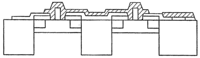
도 9a 내지 도 9c는 예시적인 디지털 빔 보조 화학 에칭 프로세스의 각종 스테이지에서의 가공물의 단면을 개략적으로 예시한 도면이다.9A-9C schematically illustrate cross-sections of a workpiece at various stages of an exemplary digital beam assisted chemical etch process.
도 10a 내지 도 10c는 예시적인 디지털 빔 보조 증착 프로세스의 각종 스테이지에서의 가공물의 단면을 개략적으로 예시한 도면이다.10A-10C schematically illustrate cross-sections of a workpiece at various stages of an exemplary digital beam assisted deposition process.
도 11a 내지 도 11c는 예시적인 디지털 빔 주입 프로세스의 각종 스테이지에서의 가공물의 단면을 개략적으로 예시한 도면이다.11A-11C schematically illustrate cross-sections of a workpiece at various stages of an exemplary digital beam injection process.
도 11e 내지 도 11i는 디지털 빔 수정 프로세스 중의 예시적인 수정을 예시한 도면이다.11E-11I illustrate exemplary modifications during the digital beam correction process.
도 12a 내지 도 12c는 제어 입자 빔으로 프로세싱된 LDD(lightly doped drain) 구조의 예시적인 개략 단면을 도시한 도면이다.12A-12C show exemplary schematic cross sections of a lightly doped drain (LDD) structure processed with a control particle beam.
도 13a 및 도 13b는 제어 입자 빔으로 프로세싱된 측방향 채널 도핑 구조의 예시적인 개략 단면 및 그 도핑 농도 프로파일을 각각 도시한 도면이다.13A and 13B show exemplary schematic cross sections and their doping concentration profiles, respectively, of a lateral channel doping structure processed with a control particle beam.
도 14a 및 도 14b는 제어 입자 빔으로 프로세싱된 이종접합(heterojunction) 절연 게이트 전계 효과 트랜지스터 구조의 예시적인 개략 단면을 도시한 도면이다.14A and 14B show exemplary schematic cross-sections of heterojunction insulated gate field effect transistor structures processed with control particle beams.
도 15는 제어 입자 빔으로 프로세싱된 시간에 대한 갈륨 비소 다이오드 구조의 예시적인 개략 단면을 도시한 도면이다.15 shows an exemplary schematic cross section of a gallium arsenide diode structure over time processed into a control particle beam.
도 16a 내지 도 16k는 제어 입자 빔으로 프로세싱된 시간에 대한 갈륨 비소 마이크로웨이브 모노리식(monolithic) 집적회로 구조의 예시적인 개략 단면을 도시한 도면이다.16A-16K illustrate exemplary schematic cross-sections of gallium arsenide microwave monolithic integrated circuit structures over time processed into control particle beams.
도 17은 제어 입자 빔으로 프로세싱된 이종접합 바이폴라(bipolar) 트랜지스터 구조의 예시적인 개략 단면을 도시한 도면이다.17 shows an exemplary schematic cross section of a heterojunction bipolar transistor structure processed with a control particle beam.
도 18은 제어 입자 빔으로 프로세싱된 시간에 대한 반도체 구조의 예시적인 개략 단면을 도시한 도면이다.18 shows an exemplary schematic cross section of a semiconductor structure over time processed into a control particle beam.
도 19a는 제어 입자 빔으로 프로세싱된 방사선 경화(radiation hardness) 구조의 예시적인 개략 평면을 도시한 도면이다.19A shows an exemplary schematic plane of a radiation hardness structure processed with a control particle beam.
도 19b는 19B-19B 라인을 따라 취한 도 19a의 방사선 경화 구조의 개략적인 단면도이다.19B is a schematic cross-sectional view of the radiation cured structure of FIG. 19A taken along
도 20은 대물 렌즈 어셈블리의 확대된 단면의 개략도를 도시한 도면이다.20 is a schematic view of an enlarged cross section of the objective lens assembly.
도 21a 내지 도 21g는 빔 기록 방식을 개략적으로 도시한 도면이다.21A to 21G are diagrams schematically showing the beam recording method.
본 명세서에서 개시된 발명의 이러한 특징 및 다른 특징, 양태, 및 장점에 대해서는, 발명을 한정하기 위한 것이 아니라 예시하기 위한 것인 바람직한 실시예의 도면을 참조하여 아래에서 설명할 것이다.These and other features, aspects, and advantages of the inventions disclosed herein will be described below with reference to the drawings of preferred embodiments, which are intended to illustrate rather than limit the invention.
특정한 바람직한 실시예 및 예들이 아래에 개시되어 있지만, 본 발명은 구체적으로 개시된 실시예 및/또는 발명의 사용 및 그 명백한 변형 및 등가물에도 확장된다는 것을 당업자가 이해할 것이다. 따라서, 본 명세서에서 개시된 발명의 범위는 아래에 설명된 구체적으로 개시된 실시예에 의해 한정되지 않아야 한다는 점을 의도한 것이다.While certain preferred embodiments and examples are set forth below, those skilled in the art will understand that the invention extends to the use of the specifically disclosed embodiments and / or inventions and their apparent variations and equivalents. Thus, it is intended that the scope of the inventions disclosed herein should not be limited by the specifically disclosed embodiments described below.
더 작은 소자 구조는 대전 입자(charged particle)의 빔으로 직접 기록하여 달성될 수도 있다. 일반적으로, 집속 이온 빔(FIB : focused ion beam) 시스템은 높은 스루풋(throughput)의 제조를 지원하기에 충분한 이온 노광을 가지지 않는다. 또한, 반도체 소자로 패터닝된 층의 효율적인 직접 기록을 방지하는 기존의 이온 광학기기/편향 전자기기 방법론을 이용하면, 비교적 낮은 속도의 편향만이 가능하다. 이와 같이, FIB는 마스크(예를 들면, 레티클) 및 반도체 리페어(repair)에 한정되었다. FIB 기술이 발전함에 따라, 레지스트를 사용하지 않고 가공물에 직접 패턴을 증착, 에칭 및 주입하는 것을 동시에 수행할 수 있는 능력을 지원하였다. 그러나, 웨이퍼 기록 소프트웨어를 거의 내지 전혀 갖지 않는 낮은 에너지 시스템의 문제, 메트롤로지(metrology) 시스템이 없는 문제와, 높은 제조 스케일의 리소그래피를 지원하기 위해 필요한 최소의 빔 전류 밀도 및 편향 속도의 문제를 포함하는 문제들이 남아 있었다. 본 명세서에서 설명된 실시예에 따른 FIB 시스템에 대한 변형 및 개선은 반도체 가공물 및 다른 매체(예를 들면, 포토마스크(photomask), 컴팩트 디스크(CD : compact disk), 디지털 비디오 디스크(DVD : digital video disk), 고해상도 DVD(high definition DVD), 블루레이(Blue-Ray) 등)의 레지스트 프로세싱 및 레지스트 없는 가공의 양자에 있어서 적당한 제조 스루풋을 달성할 수 있다.Smaller device structures may be achieved by writing directly into the beam of charged particles. In general, a focused ion beam (FIB) system does not have sufficient ion exposure to support the manufacture of high throughput. In addition, using a conventional ion optics / deflection electronics methodology that prevents efficient direct writing of the patterned layer into a semiconductor device, only relatively low speed deflections are possible. As such, the FIB is limited to a mask (eg, a reticle) and a semiconductor repair. As FIB technology has evolved, it has supported the ability to simultaneously deposit, etch and inject patterns directly into a workpiece without using resist. However, the problem of low energy systems with little or no wafer writing software, the lack of metrology systems, and the problem of the minimum beam current density and deflection speed needed to support high manufacturing scale lithography The problems involved included. Modifications and improvements to the FIB system according to the embodiments described herein include semiconductor workpieces and other media (eg, photomasks, compact disks (CDs), digital video disks (DVDs). Appropriate manufacturing throughput can be achieved in both resist processing and resist-free processing of disks, high definition DVDs, Blue-Ray and the like.
축을 따라 이동하며 그 축을 가로지르는 분포를 갖는 대전 입자의 빔에 대한 물리적 속성은 높은 속도의 디지털(또는 "펄스화된") 분포 기록 빔을 제공하도록 변형될 수 있다. 가속된 입자(본 명세서에서는 "디지털화된 빔(digitized beam)"이라 함)의 세로 경로에서 이동하는 시간 및 공간적으로 정의된 높은 밀도의 대전 입자 노드 및 낮은 밀도(또는 밀도가 없음)의 안티-노드(anti-node)의 파동(wave)을 형성하기 위해 각종 방법들이 이용될 수 있다. 예를 들어, 대전 입자의 국소화된 그룹들(또는 "플래시들" 또는 "패킷들")을 형성하기 위해 빔 번처(beam buncher)가 이용될 수 있다. 대전 입자의 이러한 그룹들은 하나 이상의 대전 입자를 포함할 수도 있다. 다음으로, 디지털 빔은 편향기로 전달되고, 편향기에서의 전압 변동은 대전 입자의 그룹들이 전파(propagation) 방향에 대한 위치를 변경하도록 한다. 전압 변화는 입자 노드에서 위상이 맞추어질 수 있음으로써, 효율적인 편향을 얻는다. 안티노드의 예리한 에지의 존재는 직접 기록에 대해 신속한 빔 블랭킹(blanking)을 효율적으로 제공한다. 디지털화된 빔을 가공물의 표면에 인가하는 것은 가공물의 표면에 대한 재료의 증착, 에칭, 및/또는 주입을 포함하는 레지스트 없는 패터닝 프로세싱, 및/또는 높은 해상도의 레지스트 노광을 가능하게 한다.The physical properties of the beam of charged particles moving along an axis and having a distribution across that axis can be modified to provide a high speed digital (or “pulsed”) distribution recording beam. Time- and spatially-defined high-density charged particle nodes and low-density (or no-density) anti-nodes traveling in the longitudinal path of accelerated particles (hereafter referred to as "digitized beams") Various methods may be used to form a wave of anti-nodes. For example, a beam buncher may be used to form localized groups of charged particles (or “flashes” or “packets”). Such groups of charged particles may comprise one or more charged particles. Next, the digital beam is delivered to the deflector, and the voltage fluctuations in the deflector cause the groups of charged particles to change their position in the direction of propagation. The voltage change can be phased at the particle node, thus obtaining an efficient deflection. The presence of the sharp edges of the antinodes efficiently provides fast beam blanking for direct writing. Applying the digitized beam to the surface of the workpiece enables resist-free patterning processing, including deposition, etching, and / or implantation of material onto the surface of the workpiece, and / or high resolution resist exposure.
도 1a는 본 명세서에서 개시된 특정 실시예에 따른 예시적인 장치(100)의 사시도이다. 도 1b는 도 1a의 장치(100)의 개략적인 평면도이다. 장치(100)는 노광 챔버(102), 로드락(load lock) 챔버(104), 이송 모듈(106) 및 복수의 프로세싱 챔버(108)를 포함한다. 예시되지는 않았지만, 장치(100)는 이후에 상세하게 설명되는 가스 매니폴드(manifold) 시스템 및 자동화된 프로세스 제어기를 포함한다는 점을 이해할 것이다.1A is a perspective view of an
로드락 챔버(104)는 예를 들면, 장치(100)에서의 프로세싱 전 및/또는 프로세싱 후에 프로세싱되지 않는 가공물(101)을 실장할 수도 있다. 특정 실시예에서는, 로드락 챔버(104)와 통신하는 이송 모듈(106)의 자동화된 재료 핸들링 시스템(AMHS : automated material handling system)(110)이 각 이송 사이에 진공으로 펌핑 다운 또는 펌핑 업 될 필요 없이 가공물(101)을 삽입 및/또는 제거할 수 있도록, 로드락 챔버(104)가 진공을 획득하도록 구성되어 있다. 특정 실시예에서는, 로드락 챔버(104)가 정면 개구 통합형 포드(FOUP : front opening unified pod)를 수용하도록 구성되어 있다.The
이송 모듈(106)은 장치(100) 내에서 가공물(101)을 이동하도록 구성되어 있다. 이송 모듈(106)은 적어도 하나의 가공물(101)을 조작하도록 구성된 AMHS(110)를 포함한다. 노광 챔버(102), 로드락 챔버(104), 이송 모듈(106) 및/또는 프로세싱 챔버(108)의 설계에 기초하여 적당한 AMHS(110)가 선택될 수 있다. 특정 실시예에서는, 가공물(101)이 동시에 (또는 병렬로) 조작될 수 있도록, AMHS(110)가 복수의 이송 아암(transport arm)을 포함한다.The
일부 실시예에서는, 이송 아암(110)에 의해 제거된 후에 노광 챔버(102) 또는 프로세싱 챔버(108)에 위치하게 되는 가공물(101)이 노광 챔버(102) 또는 프로세싱 챔버(108)에서의 프로세싱을 준비하는 배치 상태(orientation)가 되도록, 이송 모듈(106)은 가공물 예비 정렬기(prealigner)를 포함한다. 예를 들면, 예비 정렬기는 전하 결합 소자(CCD : charge-coupled device) 또는 다른 촬영 소자를 이용하여 가공물(101)의 플랫(flat), 노치(notch) 또는 다른 식별 피쳐의 위치를 정할 수도 있다. 일부 실시예에서, 예비 정렬기는 가공물(101)에 대한 정렬 피쳐의 오버레이 파라미터를 결정하도록 구성되어 있다. 오버레이 파라미터는 x 및 y 오프셋(offset), 회전 등을 포함할 수도 있다.In some embodiments, the
가공물(101)의 타입 및 크기에 따라, 다양한 진공 및 핸들링 시스템이 장치(100)에서 이용될 수 있다. 다양한 가공물을 프로세싱할 수 있는 시스템은 높은 속도의 가공물 핸들링 시스템을 이용하는 것이 바람직하다. 가공물을 진공으로 하기 위한 스루풋은 진공 시스템 외부 대신에 가공물 스테이지 상에서 진공 상태의 가공물을 정렬함으로써 증가될 수 있다. 표준적인 가공물 홀더(예를 들면, 웨이퍼 매거진(wafer magazine))는 수 분(minute) 내에 높은 진공으로 펌핑될 수 있다. 진공 상태인 가공물(101)의 정렬은 웨이퍼가 진공으로 되는 스루풋을 증가시킬 수도 있다.Depending on the type and size of the
일부 실시예에서, 이송 모듈(106)은 하나 이상의 프로세싱 서브스테이션(substation)을 포함하며, 예를 들면, 프로세싱 단계 사이에 가공물(101)을 지지하기 위한 하나 이상의 버퍼 구역(buffer zone), 입자 오염 검출기, 온도 퀀칭 스테이션(quenching station), 및/또는 메트롤로지 스테이션을 포함한다. 메트롤로지 스테이션은 다음으로 한정되지는 않지만, 에너지 분산형 분석기(EDS : energy dispersive analyzer), 파장 분산형 분석기(WDS : wavelength dispersive analyzer), 2차 이온 질량 분석기(SIMS : secondary ion mass spectrometer), 주사 전자 현미경(SEM : scanning electron microscope), 2차원 레이저 주사 촬영기, 3차원 촬영 레이저 레이더(LADAR), 열 촬영기, 밀리미터 파 촬영기, 가공물 촬영기, 및 카메라를 포함하는, 가공물의 타입에 적합한 임의의 툴로부터 선택될 수도 있다.In some embodiments, the
노광 챔버(102)는 가공물(101)을 대전 입자의 디지털 빔에 노광하도록 구성되어 있다. 도 2에 도시된 바와 같이, 노광 챔버(102)는 도 3a에 더욱 상세하게 예시된 빔 컬럼(beam column)(200)을 포함한다. 빔 컬럼(200)은 대전 입자의 스트림을 생성하기 위한 대전 입자 소스(202)를 포함한다. 시스템 및 방법은 이온을 참조하여 본 명세서의 특정 실시예에서 설명되고 있지만, 일부 시스템 및 방법은 전자 및 양전자(positron)를 포함하는 대전 입자를 이용할 수도 있음을 이해할 것이다. 대전 입자는 단독, 2중으로, 3중으로 등과 같이 대전된 이온뿐만 아니라 양(positive) 및 음(negative)으로 대전된 이온의 하나 이상의 종류를 포함할 수도 있다. 일부 실시예에서, 대전 입자 소스(202)는 복수의 이온 종류를 생성하도록 구성되어 있다. 일부 실시예에서, 대전 입자 소스(202)는 타겟(target)에서 측정된 바와 같이 10 nm 스폿(spot)에 집속되는 1000 amperes/cm2(A/cm2)의 전류를 제공하도록 구성되어 있다.The
액체 금속 이온 소스(LMIS : liquid metal ion source) 기술은 높은 전류 밀도의 대전 입자 빔의 형성을 가능하게 한다. LMIS를 생성하기 위한 예시적인 기술은 니들(needle)이 아래로 돌출되어 있는 액체 금속의 가열된 저장소이다. 금속은 모세관 작용에 의해 니들의 아래로 흐른다. 추출 전극으로부터의 전기장은 니들 첨단의 액체를 이온이 방출되는 뾰족한 돌기("테일러 콘(Taylor Cone)")로 밀어낸다. 포인트 소스(point source)는 매우 밝으며(예를 들면, 약 109 A/steradian/cm2), 적당한 광학기기에 의해 빔 직경을 2nm 정도로 작게 할 수 있다. 다양한 합금은 반도체 가공을 위해 공통적인 몇 개의 이온 종류를 제공한다.Liquid metal ion source (LMIS) technology enables the formation of high current density charged particle beams. An exemplary technique for producing LMIS is a heated reservoir of liquid metal with needles protruding down. The metal flows down the needle by capillary action. The electric field from the extraction electrode pushes the liquid at the tip of the needle into a sharp projection (“Taylor Cone”) where ions are released. The point source is very bright (e.g., about 10 9 A / steradian / cm 2 ) and the beam diameter can be as small as 2 nm by suitable optics. Various alloys provide several common ionic species for semiconductor processing.
이온의 분포 에너지를 가속 및 집속하는 것은 이온 광학 시스템의 전류 밀도 효율의 손실을 발생하는 색수차(chromatic aberration)를 도입할 수 있다. 이온 빔 에너지 분포는 빔의 FWHM(full-width-half-max)으로서 측정될 수 있고, 12% 만큼 많이 분포될 수 있다. 전류 밀도 효율을 개선시키고 장기 및 단기 안정도 문제를 해결하는 것은 LMIS 성능이 반도체 프로세싱 툴에 적합하도록 할 수 있다. 본 발명의 다양한 실시예의 하나의 양태는 대전 입자의 빔이 그룹화에 유리할 수 있는 높고 낮은 에너지 궤적의 분포로 구성되도록 실현한 것이다.Accelerating and focusing the distribution energy of ions can introduce chromatic aberrations that result in a loss of current density efficiency of the ion optical system. The ion beam energy distribution can be measured as the full-width-half-max (FWHM) of the beam and can be distributed as much as 12%. Improving current density efficiency and solving long and short term stability issues can make LMIS performance suitable for semiconductor processing tools. One aspect of various embodiments of the present invention is to realize that a beam of charged particles consists of a distribution of high and low energy trajectories that may be advantageous for grouping.
적어도 2개의 메커니즘, 즉, 이온의 형성과 관련된 효과와, 이온 형성 후의 공간 전하력(space charge force)은 에너지 분포의 확대에 기여할 수 있다. 이미터(emitter) 첨단에서의 이온의 직접 필드 이탈에 의해, 또는 이미터 첨단으로부터 약간의 거리에서 이탈된 원자의 필드 이온화에 의해 LMIS 소스로부터의 이온 방출이 형성된다. 첨단 표면에 근접하게 생성된 이온은 그 지점에서 제로 에너지 이온을 강제하는 더욱 하부(downstream)의 중립 원자와 전하를 교환할 수 있다. 이미터 영역의 전기장은 높으므로(예를 들면, 약 20 및 50 Volts/nm 사이), 이미터로부터 상이한 거리에 형성된 이온은 상이한 에너지를 가질 수 있다. 공간 전하 효과는 특히 낮은 속도에서 빔의 에너지 분포를 확대시킨다. 그러므로, 컬럼(200)은 이온의 형성 직후에 이온을 전체 에너지로 가속하도록 구성되는 것이 바람직하다. 낮은 질량의 종류를 사용하는 것은 이러한 종류의 사용이 적합할 경우에 이온 가속을 도울 수 있다.
공간 전하 효과는 더 높은 전류에 의해 악화되기도 한다. LMIS 소스에 대해서는, 에너지 분포의 폭이 2/3 전력에 대한 전류에 비례하는 것이 바람직하다. 이와 같이, 전통적인 LMIS 소스를 리소그래피에 실제적으로 적용하는 것은 전자 빔과 유사한 거동을 보여준다.At least two mechanisms, namely the effects associated with the formation of ions, and the space charge force after ion formation can contribute to the expansion of the energy distribution. Ion release from the LMIS source is formed by direct field departure of the ions at the emitter tip, or by field ionization of the atoms deviating some distance from the emitter tip. The ions generated in close proximity to the tip surface can exchange charge with the more neutral neutral atoms that force zero energy ions at that point. Since the electric field in the emitter region is high (eg, between about 20 and 50 Volts / nm), ions formed at different distances from the emitter can have different energies. The space charge effect enlarges the energy distribution of the beam, especially at low speeds. Therefore, the
Space charge effects are often exacerbated by higher currents. For LMIS sources, it is desirable for the width of the energy distribution to be proportional to the current for 2/3 power. As such, the practical application of traditional LMIS sources to lithography shows behavior similar to electron beams.
LMIS-기반 시스템으로 획득 가능한 최대의 전류 밀도에 관한 제한은 상부의 이온 광학 시스템에서의 색지움 수차(achromatic aberration)에 의해 발생하는 이온 빔의 에너지 분포로 인한 결과이다. 그러나, 전파 축을 따라 대전 입자의 시간 및 공간적으로 분해된 그룹을 생성하기 위해 대전 입자 사이의 세로 간격을 조정하도록 구성되어 있는 대전 입자 소스(202)의 하부에 위치한 빔 디지타이저(206)의 사용은 더 빨리 이동하는 입자를 효율적으로 느리게 할 수 있고 더 느리게 이동하는 입자를 빠르게 하여 디지털 빔의 각 그룹 내에서 균일한 속도와 이에 따른 균일한 에너지 분포(가속 전압)를 얻음으로써, 도 3b에 예시된 바와 같이, 대전 입자 소스 색수차의 효과를 감소시킬 수 있다.The limitation on the maximum current density achievable with LMIS-based systems is the result of the energy distribution of the ion beam caused by achromatic aberration in the upper ion optical system. However, the use of the
전자 빔의 이동과 유사하게, LMIS 테일러 콘(Taylor cone) 방출은 약 1시간 주기에 걸쳐 피겨-8(figure-8) 패턴으로 예측 불가능하게 드리프트(drift)한다. 검출되지 않는 이 드리프트는 패턴 배치 에러를 야기할 수 있다. 소스 존속 기간 및 전류 안정도는 전통적인 LMIS 소스를 이용한 스루풋 프로세싱 툴을 생성하기 위한 실제적인 응용에 대한 장벽이다. 대전 입자 소스(202)의 또 다른 개선은 안정도 및 존속 기간을 개선시킴으로써 빈번한 소스 변위를 감소시킬 수 있다. 이온 형성과 관련된 에너지 분포의 확대는 LMIS를 낮은 온도에서 동작시킴으로써 감소 또는 최소화될 수 있으며, 이에 따라, 첨단 근처에서 중립 원자 밀도를 감소시킬 수 있다. 또한, 낮은 증기압 종류를 선택함으로써, 예를 들면, 낮은 전하 교환 단면을 가지며 좁은 에너지 분포를 갖는 것으로 알려진 첨단의 표면에 형성된 2중으로 이온화된 종류를 선택하고, 작은 가상 소스의 추가적인 이점을 갖는 종류를 이용함으로써, 에너지 분포가 감소 또는 최소화될 수 있다. 다른 기술도 이용될 수 있음을 알 수 있을 것이다.Similar to the movement of the electron beam, the LMIS Taylor cone emission drifts unpredictably in a figure-8 pattern over about an hour period. This undetected drift can cause a pattern placement error. Source duration and current stability are barriers to practical applications for creating throughput processing tools using traditional LMIS sources. Another improvement of the charged
특정 실시예에서는, 동작 이전에 소스 구동 파라미터를 조절함으로써 대전 입자 소스(202)의 연장된 존속 기간이 달성될 수도 있다. 이와 같이, 자동화된 조절 루틴(routine)의 포함은 대전 입자 소스(202)의 연장된 존속 기간 및 안정도에 기여할 수 있다. 또한, 경화된 첨단을 갖는 함침된(impregnated) 전극형 니들과 같은 연속 흐름 방식은 대전 입자 소스(202)의 존속 기간을 더욱 연장할 수 있다. 개선된 존속 기간의 2차적인 효과는 방출 전류 및 위치 안정도 개선을 포함할 수 있다. 소스 방출 위치 안정도는 소스 서보모터(servomotor)에 대한 비정기적인 빔 등록 및 조정으로부터의 에러 피드백을 이용함으로써 성공적으로 보정될 수 있다. 증 가된 이온 빔 전류 밀도가 바람직하지만, 노광 챔버(102)의 컬럼(200)은 빔 전류 밀도를 증가시킬 필요가 없다.In certain embodiments, an extended duration of
다른 대전 입자 소스(202)는 본 명세서에서 설명된 실시예에서 이용될 수도 있다. 예를 들면, 이하의 것으로 한정되지 않지만, 대전 입자 소스(202)는 플라즈마 이온 소스(PIS : plasma ion source), 공간 플라즈마 이온 소스(VPIS : volume plasma ion source), 가스 필드 이온화 소스(GFIS : gas field ionization source), 탄소 나노튜브 필드 이미터, 자유 전자 레이저 및 타겟, 펄스화된 레이저 제거 이온 소스, 자기 구속 플라즈마 어노드 소스(MAP : magnetically confined plasma anode source) 및 열 필드 방출(TPE : thermal field emission) 전자 소스를 포함할 수도 있다.Other charged
대전 입자 소스(202)로부터 발산되는 대전 입자의 스트림은 콜리메이터(collimator)(204)에 의해 콜리메이트(collimate) 되어 축을 따라 진행된다. 광학 소자들의 조합을 포함하는 다양한 콜리메이터(204)는 컬럼(200)에서 사용하기에 적합하다. 예를 들면, 이하의 것으로 한정되지 않지만, 콜리메이터(204)는 둘 이상의 렌즈 또는 하나의 렌즈 및 반사형 광학기기를 포함할 수도 있다. 콜리메이터(204)는 대전 입자 빔을 성형(shape)하도록 구성된 개구(aperture)를 더 포함할 수도 있다. 특정 실시예에서, 콜리메이터는 약 5 및 30 킬로 전자 볼트(keV) 사이의 가속 전위에서 대전 입자 스트림을 진행시키도록 구성되어 있다. 특정 실시예에서, 노광 챔버(102)는 약 5 및 500 keV 사이의 가속 전위에서 대전 입자 스트림을 진행시키도록 구성되어 있다. 일부 실시예에서, 콜리메이터(204)의 전압은 예를 들면, 하부의 컬럼 출구 개구에 의해 인가되는 추가적인 전압에 더해진다.The stream of charged particles emanating from the charged
대전 입자 소스(202)가 복수의 이온 종류를 생성하도록 구성되어 있는 실시예에서는, 대전 입자 스트림을 입자 필터(예를 들면, 분광계 필터(spectrometer filter))로 필터링함으로써 특정한 프로세싱 어플리케이션에 대해 개별적인 이온 종류가 선택될 수 있다. 예를 들면, 질량 분리기는 선택된 이온 종류를 질량 분리기 개구 판으로 편향시키도록 구성될 수 있다. 질량 분리기는 콜리메이터(204) 및 빔 디지타이저(206) 사이에 배치되는 것이 바람직하다. 일부 실시예에서, 질량 분리기는 반사형 광학기기를 포함한다. 일부 실시예에서, 질량 분리기는 ExB 렌즈를 포함한다. 일부 실시예에서는, 질량 분리기가 바인 필터(Wein filter)를 포함한다.In embodiments where the charged
빔 디지타이저(206)는 전파 축을 따라 대전 입자 사이의 세로 간격을 조정함으로써 적어도 하나의 대전 입자의 개별 그룹을 포함하는 디지털 빔을 생성하도록 구성되어 있다. 특정 실시예에서, 빔 디지타이저(206)는 약 1 및 7,000,000개 사이의 대전 입자, 약 1 및 100,000개 사이의 대전 입자, 약 1 및 10,000개 사이의 대전 입자, 또는 약 1 및 50,000개 사이의 대전 입자를 포함하는 그룹을 생성하도록 구성되어 있다. 일부 실시예에서, 빔 디지타이저(206)는 대전 입자의 그룹 사이의 빔 이동의 약 10 m 미만, 빔 이동의 약 1 m 미만, 빔 이동의 약 10 cm 미만, 빔 이동의 약 10 mm 미만, 빔 이동의 약 1 mm 미만, 빔 이동의 약 500 ㎛ 미만, 빔 이동의 약 300 ㎛ 미만, 빔 이동의 약 100 ㎛ 미만, 빔 이동의 약 10 ㎛ 미만, 빔 이동의 약 100 nm 미만, 빔 이동의 약 10 nm 미만, 또는 빔 이동의 약 1 nm 미만의 대전 입자의 그룹 사이의 세로 간격 D를 생성하도록 구성되어 있다. 일부 실시예에서, 빔 디지타이저(206)는 빔 이동의 약 1 nm 및 10 m 사이, 빔 이동의 약 1 nm 및 1 m 사이, 빔 이동의 약 1 nm 및 10 cm 사이, 빔 이동의 약 1 nm 및 10 mm 사이, 빔 이동의 약 1 nm 및 1 mm 사이, 빔 이동의 약 1 nm 및 500 ㎛ 사이, 빔 이동의 약 1nm 및 300 ㎛ 사이, 빔 이동의 약 1 nm 및 100 ㎛ 사이, 빔 이동의 약 1 nm 및 10 ㎛ 사이, 빔 이동의 약 1 nm 및 100 nm 사이, 또는 빔 이동의 약 1 nm 및 10 nm 사이의 대전 입자의 그룹 사이의 세로 간격을 생성하도록 구성되어 있다. 대전 입자의 그룹 사이의 세로 간격은 실질적으로 동일, 동일하지 않거나, 주기적이거나, 고조파(harmonic) 등일 수도 있다.The
특정 실시예에서, 빔 디지타이저(206)는 빔 번처를 포함한다. 무선 주파수(RF : radio frequency) 빔 번처에서는, 대전 입자의 스트림이 교류 전위, RF 또는 다중 변조 전위 파 형태, 비트(beat) 파, 고조파, 변수 또는 그 조합이 작용하는 번처 갭(gap)을 통과한다. 속도 변조는 대전 입자가 대전 입자의 시간 및 공간적으로 분해된 개별적인 그룹을 형성하도록 대전 입자를 모두 압축한다. 특정 실시예에서, 주파수 및 번처 갭 길이는 대전 입자의 그룹의 평균 속도와 일치하도록 구성되어 있다. 각 대전 입자가 번처 갭을 통과할 때, (예를 들면, 도 3b에 도시된 바와 같이) 일부의 대전 입자(예를 들면, 평균 속도보다 낮은 속도를 갖는 대전 입자)는 가속되고, 다른 대전 입자(예를 들면, 평균 속도보다 높은 속도를 갖는 대전 입자)는 감속되도록, 인가된 전위는 각 대전 입자의 세로 속도를 변조시킨다. 번처 갭의 갭 길이, 인가된 전위의 크기 및 주파수와, 컬럼(200)을 통과하는 대전 입자의 비행 시간(TOF : time of flight)은 가공물(101) 표면에서의 디지털 빔 및 대전 입자 그룹의 최종적인 특성을 결정한다.In certain embodiments,
도 3c는 빔 번처를 관통하여 이동하는 대전 입자의 스트림을 개략적으로 도시한 것이다. 번처 갭 G에 의해 분리되어 있는 빔 번처의 전극(302, 304) 양단에는 전위가 인가될 수 있다. 그 후에 변경되지 않으면, 대전 입자가 빔 번처를 통과한 후에 얼마나 멀리 이동한 것인지에 따라 길이 L 및 분리 (간격) D가 결정되는 그룹을 대전 입자는 형성하기 시작한다. 일부 실시예에서, 빔 번처는 대전 입자를 이동 중에 그룹으로 압축하도록 구성되어 있다. 일부 실시예에서, 빔 번처는 대전 입자의 그룹을 세로로 압축하기 위한 전기장을 인가하도록 구성되어 있다. (예를 들면, 도 3c에 도시된 바와 같이) 대전 입자는 가공물(101)에 도달할 경우에 세로로 완전히 압축되는 것이 바람직하다. 번처에 의해 인가되는 에너지는 대전 입자의 스트림의 초기 에너지와, 대전 입자의 시간 및 공간적으로 분해된 그룹의 최종 에너지 사이의 차이에 의해 결정될 수 있다.3C schematically depicts a stream of charged particles moving through a beam buncher. A potential may be applied across the
특정 실시예에서, 빔 번처는 복수의 번처 전극 및 그에 따른 복수의 번처 갭을 포함한다. 디지털 빔의 특성을 변경하기 위하여, 2개의 전극 양단에 전위가 선택적으로 인가될 수 있다. 예를 들면, 1 ㎛의 번처 갭 G를 갖는 전극 양단에 전위가 인가되어 더 낮은 대전 입자 밀도를 갖는 노드를 생성할 수 있고, 3 cm의 번처 갭 G를 갖는 전극 양단에 전위가 인가되어 더 높은 대전 입자 밀도를 갖는 노드를 생성할 수 있다.In a particular embodiment, the beam buncher includes a plurality of buncher electrodes and thus a plurality of buncher gaps. In order to change the characteristics of the digital beam, a potential can be selectively applied across the two electrodes. For example, a potential may be applied across the electrode with a buncher gap G of 1 μm to produce a node with a lower charged particle density, and a potential may be applied across the electrode with a buncher gap G of 3 cm to give a higher It is possible to create nodes with charged particle density.
빔 에너지 및 번처 전류, 주파수, 및 갭 길이와 같은 빔 번처 입력 파라미터와, 분리 간격 D, 길이 L 및 밀도와 같은 빔 번처 출력 특성 사이의 관계는 잘 알려져 있다. 빔 번처는 그룹 당 대전 입자의 소정 수를 제공하도록 동작하는 것이 바람직하다. 첫째, 번처 갭, 주파수 및 빔 에너지는 전류가 조정되는 동안에 일정하게 유지될 수 있다. 둘째로, 빔 에너지 및 번처 전류는 번처 갭 및 주파수가 조정되는 동안에 일정하게 유지될 수 있다. 다른 동작 구성도 가능하다.The relationship between beam buncher input parameters such as beam energy and buncher current, frequency, and gap length and beam buncher output characteristics such as separation spacing D, length L and density are well known. The beam buncher preferably operates to provide a predetermined number of charged particles per group. First, the buncher gap, frequency and beam energy can be kept constant while the current is adjusted. Secondly, the beam energy and the buncher current can be kept constant while the buncher gap and frequency are adjusted. Other operating configurations are possible.
일부 실시예에서, 빔 번처는 전류 주파수에 의해 변조되어 자기장을 발생하는 나선형 코일을 포함한다. 코일 회전 사이의 세로 간격("갭(gap)")과, 인가 전류의 크기 및 주파수와, 컬럼(200)을 관통하는 대전 입자의 비행 시간(TOF)은 가공물(101)의 표면에서의 디지털 빔의 최종 특성을 결정한다. 특정 실시예에서, 주파수와 코일의 회전 사이의 세로 간격은 디지털 빔의 평균 속도와 일치하도록 구성되어 있다.In some embodiments, the beam buncher includes a helical coil that is modulated by the current frequency to generate a magnetic field. The longitudinal spacing ("gap") between coil turns, the magnitude and frequency of the applied current, and the flight time (TOF) of the charged particles passing through the
대전 입자를 번칭(bunching)하는 것은 전술한 바와 같이, 대전 입자 밀도를 변동시키는 빔 번처 주파수, 진폭 및 듀티 사이클을 변동시킴으로써, 대전 입자 레벨에서의 도스(dose) 변동량에 의한 기록 방식 최적화를 가능하게 한다. 그러므로, 빔 번처 파라미터는 기록 방식에 따라 조정되는 것이 바람직하다.Bunching the charged particles enables the optimization of the recording method by the amount of dose variation at the charged particle level by varying the beam buncher frequency, amplitude, and duty cycle, which vary the charged particle density, as described above. do. Therefore, the beam buncher parameter is preferably adjusted according to the recording scheme.
특정 실시예에서, 빔 디지타이저(206)는 빔 블랭커(blanker)(예를 들면, 디지털 빔을 생성하기에 충분한 속도로 동작할 수 있는 빔 블랭커)를 포함한다. 예를 들면, 이하의 것으로 한정되지 않지만, 고속 블랭커는 특정 간격의 대전 입자 빔을 흡수하도록 구성된 개구 판을 포함할 수도 있다. 개구 판의 내부 에지에 근접한 개구 판의 개구에 스트림이 통과하도록, 개구 판이 초기에 위치되어 있다. 입자의 흐름을 차단하여 시간 및 공간적으로 분해된 디지털 빔을 생성하는 개구 판에 스트림을 편향시키도록 전극이 구성되어 있다. 도 3d는 고속 블랭커를 통과하여 이동하는 대전 입자의 스트림을 개략적으로 도시한 것이다. 개구 판(316)은 대전 입자의 스트림에 근접하게 위치되어 있다. 대전 입자 스트림에 전위를 인가하여 디지털 빔의 대전 입자의 시간 및 공간적으로 분해된 그룹을 생성하도록, 전극(312, 314)이 구성되어 있다. 그 후에 변경되지 않으면, 대전 입자가 고속 블랭커를 통과한 후에 얼마나 멀리 이동한 것인지에 관계없이, 대전 입자는 길이 L 및 분리 간격 D로 계속하여 이동한다.In a particular embodiment, the
빔 디지타이저(206)의 다른 실시예도 가능하다. 일부 실시예에서, 빔 디지타이저(206)는 대전 입자 소스(202)의 온/오프 상태를 변조하도록 구성되어 있다. 일부 실시예에서, 빔 디지타이저(206)는 대전 입자의 그룹을 변위시키기 위하여 축에 세로 방향인 대전 입자 소스(202)의 위치를 변조시키도록 구성되어 있다.Other embodiments of the
일부 실시예에서, 빔 디지타이저(206)는 예를 들면, 약 1 메가헤르쯔(MHz) 및 100 기가헤르쯔(GHz) 사이, 또는 약 1 MHz 및 25 GHz 사이의 주파수를 갖는 전자기 방사선을 인가하도록 구성되어 있다. 이러한 실시예에서, 빔 디지타이저(206)는 예를 들면, 전자기 방사선의 진폭, 전자기 방사선의 주파수, 그 조합 등을 변조하도록 구성될 수 있다. 일부 실시예에서, 빔 디지타이저(206)는 대전 입자를 포함하는 플라즈마에 비트 파를 인가하도록 구성되어 있다. 일부 실시예에서, 빔 디지타이저(206)는 공간 전하(space charge)를 웨이크 필드(wake field)에 인가하도록 구성되어 있다. 이러한 실시예에서, 빔 디지타이저(206)는 공간 전하를 공진에 의해 흡수하도록 구성될 수 있다. 일부 실시예에서, 빔 디지타이저(206)는 흡수 개구를 통해 빔을 블랭크(blank)하도록 구성되어 있다. 일부 실시예에서, 빔 디지타이 저(206)는 펄스화된 입사 중립화 빔(pulsed incident neutralizing beam)을 대전 입자 소스(202)에 인가하도록 구성되어 있다. 일부 실시예에서, 빔 디지타이저(206)는 펄스화된 레이저 빔을 대전 입자 소스(202)에 인가하도록 구성되어 있다.In some embodiments, the
특정 실시예에서, 본 명세서에서 설명된 구성요소는 합성되는 것이 유리하다. 하나의 실시예에서, 컬럼(200)은 콜리메이터(204)의 하부에 위치한 빔 블랭커와, 빔 블랭커의 하부에 위치한 빔 번처를 포함한다. 빔 블랭커로부터 나와서 빔 번처를 향하는 디지털 빔은 디지털 빔에서 개별적인 그룹을 시간 및 공간적으로 더욱 분해하기 위해 이용될 수 있다. 또 다른 실시예에서, 컬럼(200)은 콜리메이터(204)의 하부에 위치한 빔 번처와, 빔 번처의 하부에 위치한 빔 블랭커를 포함한다. 다른 구성도 가능하다.In certain embodiments, the components described herein are advantageously synthesized. In one embodiment,
컬럼(200)은 빔 디지타이저(206)의 하부에 위치한 편향기(210)를 더 포함한다. 편향기(210)는 디지털 빔의 축을 따라 세로로 배치된 일련의 편향 스테이지(예를 들면, 전극 스테이지, 자기 스테이지)를 포함한다. 편향기(210)는 디지털 빔의 대전 입자의 개별적인 그룹을 편향시킨다. 본 명세서에서 사용된 바와 같이, "소수 필드 편향(minor field deflection)"이란 문구는 편향기(210)에 의한 대전 입자의 개별적인 그룹의 편향을 말한다. 일부 실시예에서, 편향기(210)는 디지털 빔의 그룹을 전파 축에 실질적으로 수직으로 편향시키도록 구성되어 있다. 특정 실시예에서, 편향기는 약 1 및 1000 사이, 또는 4개의 편향 스테이지를 포함한다. 특정 실시예에서, 편향기는 적어도 하나, 2개, 3개, 또는 4개의 편향 스테이지를 포함한 다. 일부 실시예에서, 각 편향 스테이지는 2개 또는 그 이상의 전극을 포함한다. 일부 실시예에서, 하나 또는 그 이상의 편향 스테이지는 4개의 전극을 포함한다. 편향 스테이지 및 전극의 다른 수량도 가능하다.The
특정 실시예에서, 디지털 빔의 대전 입자 그룹의 평균 또는 중간 속도는 약 1×10⁴ meters/second(m/s) 및 3×10⁸ m/s 사이이다. 일부 실시예에서, 각각의 편향 전극 스테이지에 의한 전위의 인가는 편향기를 통과하는 대전 입자 그룹의 평균 속도와 동기화되도록 구성되어 있다. 예를 들면, 편향 전극 스테이지는 대전 입자 그룹이 전반적으로 편향기를 통과하며, 특히 특수한 편향 전극 스테이지를 통과할 경우에만 전압을 인가하도록 구성될 수도 있다. 일부 실시예에서, 각각의 편향 전극 스테이지에 의한 인가 전위는 편향기를 통과하는 대전 입자 그룹의 평균 속도와 고조파에 의해 동기화되도록 구성되어 있다. 예를 들면, 편향기의 적어도 일부에서의 각 편향 전극 스테이지는 대전 입자의 특수한 그룹이 전반적으로 편향기를 통과하며, 특히 특수한 편향 전극 스테이지를 통과할 경우에만 전압을 인가하도록 구성될 수도 있다. 일부 실시예에서, 각각의 편향 전극 스테이지에 의한 전위의 인가는 편향기를 통과하는 대전 입자 그룹의 평균 속도와 임의로 동기화되도록 구성되어 있다. 본 명세서에서 사용된 바와 같이, 임의로 동기화된다는 문구(phrase)는 다음의 것으로 한정되지는 않지만, 임의의 간격을 갖는 대전 입자 그룹에 대한 편향 전극 스테이지에 의한 전압 인가의 동기화, 또는 임의의 또는 다른 간격을 갖는 대전 입자 그룹에 대한 임의의 편향 전극 스테이지에 의한 전압 인가의 동기화를 포함하는 가능한 가장 넓은 의미가 부여되어야 한다.In certain embodiments, the average or median velocity of the charged particle group of the digital beam is between about 1 × 10 4 meters / second (m / s) and 3 × 10 8 m / s. In some embodiments, the application of the potential by each deflection electrode stage is configured to be synchronized with the average velocity of the group of charged particles passing through the deflector. For example, the deflection electrode stage may be configured to apply a voltage only when a group of charged particles passes through the deflector, in particular through a special deflection electrode stage. In some embodiments, the applied potential by each deflection electrode stage is configured to be synchronized by the harmonics and the average velocity of the group of charged particles passing through the deflector. For example, each deflection electrode stage in at least a portion of the deflector may be configured to apply a voltage only when a special group of charged particles passes through the deflector, in particular through a special deflection electrode stage. In some embodiments, the application of the potential by each deflection electrode stage is configured to be randomly synchronized with the average velocity of the group of charged particles passing through the deflector. As used herein, the phrase to be arbitrarily synchronized is not limited to the following, but synchronization of voltage application by the deflecting electrode stage to a group of charged particles having any spacing, or any or other spacing. The broadest possible meaning should be given, including the synchronization of the application of voltage by any deflection electrode stage to the group of charged particles having a.
특정 실시예에서, 편향 스테이지의 전극은 디지털 빔의 각각의 대전 입자 그룹이 통과할 때 실질적으로 동일한 전압 전위를 인가한다. 각각의 대전 입자 그룹의 편향량은 순차적으로 활성화되는 전극의 수에 의존한다. 일부 실시예에서는, 각각의 대전 입자 그룹이 통과할 때 각각의 편향 전극 스테이지에 가변 전위가 인가된다. 예를 들면, 첫 번째 편향 전극 스테이지는 최소 전압을 가지며 이후의 전극은 점차 더 큰 전압을 가짐으로써, 전극이 활성화됨에 따라 선형 편향이 된다. 그 반대도 가능하며, 이 경우, 첫 번째 편향 전극 스테이지가 가장 큰 전압을 가지며, 이후의 전극은 점차 더 작은 전압을 가진다. 활성화된 편향 전극 스테이지의 수는 디지털 빔의 각각의 대전 입자 그룹의 편향량을 정의한다. 편향기에 인가되는 신호 타이밍 및 명목 전압은 개별적인 편향 전극 스테이지에 대해, 그리고 심지어 각각의 편향 전극 스테이지 내의 개별적인 전극에 대해 교정(calibration)될 수 있다. 예를 들면, 대전 입자 속도, 종류 및 질량에 있어서의 변경, 편향 스테이지 위치, 패턴 해상도, 패턴 필드 에러, 목표 편향 필드 내에서의 에러, 프로세스에 특수한 보상 및 기록 방식, 그 조합 등에 있어서의 변경으로 인해, 디지털 빔의 각각의 대전 입자 그룹의 입사(incidence)와 일치("위상 일치(phase-matching)")시키기 위하여, 필요하다면, 개별적인 편향 전극 스테이지의 인가 전압을 트리거(trigger)하는 것이 지연될 수 있다. 특정 실시예에서, 편향 전극 스테이지의 필드 경계는 전파 축의 중앙으로부터 x 또는 y 방향의 4 mm 미만의 변위, 2 mm 미만의 변위, 1 mm 미만의 변위, 또는 100 ㎛ 미만의 변위의 소수 편향 필드(minor deflection field)로서 정의된다.In a particular embodiment, the electrodes of the deflection stage apply substantially the same voltage potential as each group of charged particles in the digital beam passes through. The amount of deflection of each charged particle group depends on the number of electrodes sequentially activated. In some embodiments, a variable potential is applied to each deflection electrode stage as each group of charged particles passes. For example, the first deflection electrode stage has a minimum voltage and subsequent electrodes have a gradually higher voltage, resulting in linear deflection as the electrode is activated. The reverse is also possible, in which case the first deflection electrode stage has the largest voltage, and the subsequent electrodes have gradually smaller voltages. The number of activated deflection electrode stages defines the amount of deflection of each charged particle group of the digital beam. The signal timing and nominal voltage applied to the deflector can be calibrated for individual deflection electrode stages and even for individual electrodes in each deflection electrode stage. For example, change in charged particle velocity, type and mass, deflection stage position, pattern resolution, pattern field error, error in target deflection field, process-specific compensation and recording method, combinations thereof, and the like. Due to this, in order to match ("phase-matching") the incidence of each group of charged particles of the digital beam, triggering the applied voltage of the individual deflection electrode stages may be delayed if necessary. Can be. In a particular embodiment, the field boundary of the deflection electrode stage is a fractional deflection field of less than 4 mm, less than 2 mm, less than 1 mm, or less than 100 μm of displacement in the x or y direction from the center of the propagation axis. minor deflection field).
특정 실시예에서, 각각의 편향 전극 스테이지의 전위는 대전 입자 그룹을 의도한 궤도를 향해 부분적으로 변위시키도록 구성되어 있다. 각 그룹은 편향 전극 스테이지의 수 N의 각각에 의해 의도한 편향 거리의 1/N 번째만큼 부분적으로 편향된다. 특정 실시예에서, 첫 번째 편향 전극 스테이지 또는 임의의 하나의 편향 전극 스테이지는 하나 이상의 (예를 들면, 모든) 대전 입자 그룹을 의도한 궤도를 향해 실질적으로 완전히 변위시키도록 구성되어 있고, 다른 편향 전극 스테이지는 그룹의 편향을 미세 조정하기 위해 이용된다. 다른 조합도 가능하다.In certain embodiments, the potential of each deflection electrode stage is configured to partially displace the charged particle group towards the intended orbit. Each group is partially deflected by the 1 / Nth of the intended deflection distance by each of the number N of deflection electrode stages. In certain embodiments, the first deflection electrode stage or any one deflection electrode stage is configured to substantially completely displace one or more (eg, all) charged particle groups toward the intended trajectory, and the other deflection electrode The stage is used to fine tune the deflection of the group. Other combinations are possible.
일부 실시예에서, 예를 들면, 전술한 고조파에 의해 동기화된 편향기, 편향기의 적어도 일부는 N 세트의 편향 전극 스테이지를 포함하고, 각 세트의 편향 전극 스테이지는 N 개의 편향 전극을 포함하며, 모든 N 번째 편향 전극 스테이지는 대전 입자의 특수한 그룹을 의도한 궤도를 향해 변위시키도록 구성되어 있다. 편향기의 적어도 일부가 2 세트의 편향 전극 스테이지를 포함하면, 편향 전극 스테이지의 세트 내의 모든 다른 편향 전극 스테이지는 대전 입자의 특수한 그룹을 의도한 궤도를 향해 변위시키도록 구성될 수도 있다. 편향기의 적어도 일부가 3 세트의 편향 전극 스테이지를 포함하면, 편향 전극 스테이지의 세트 내의 모든 세 번째 편향 전극 스테이지는 대전 입자의 특수한 그룹을 의도한 궤도를 향해 변위시키도록 구성될 수도 있다. 다른 변형 및 구성도 가능하다.In some embodiments, for example, the deflector synchronized by the aforementioned harmonics, at least a portion of the deflector comprises N sets of deflection electrode stages, each set of deflection electrode stages includes N deflection electrodes, Every N-th deflection electrode stage is configured to displace a special group of charged particles towards the intended orbit. If at least a portion of the deflector comprises two sets of deflection electrode stages, all other deflection electrode stages in the set of deflection electrode stages may be configured to displace a particular group of charged particles toward the intended trajectory. If at least a portion of the deflector comprises three sets of deflection electrode stages, every third deflection electrode stage in the set of deflection electrode stages may be configured to displace a particular group of charged particles toward the intended trajectory. Other variations and configurations are possible.
도 6a는 각각의 편향 전극 스테이지 내에 적어도 하나의 전극을 포함하는 편향기(210)의 개략적인 평면도를 도시한 것이다. 대전 입자를 포함하는 디지털 빔은 편향기(602)의 중앙 개구를 통과하도록 구성되어 있다. 전극(604, 606) 및 전극(608, 610)의 세트는 대전 입자 그룹이 편향기의 세로 축 및 경로에 수직으로 편향되도록 양 또는 음으로 대전될 수도 있다. 바람직하게는, 대향하는 측의 전극, 예를 들어, 전극(604 및 606)은 반대로 대전되어 있다. 도 6b는 편향기(210)의 우상부 4분면의 1/4 절단 사시도이다. 전극(606)은 이 실시예에서 절연체(612)에 의해 분리되어 있다. 절연체 재료의 예는 SiO2, SiNx, SiOxNy, 그 조합 등을 포함한다. 복수의 편향 전극 스테이지를 포함하는 하나의 편향기가 아니라, 편향기(210)가 일련의 편향기를 포함하고, 각각은 하나 이상의 편향 전극 스테이지를 포함할 수도 있음을 이해할 것이다. 예를 들면, 편향기(210)는 3 세트의 편향기를 포함할 수도 있다. 도 6b에 예시된 바와 같이, 대전 입자 그룹은 경로를 따라 이동할 때 각각의 편향 전극 스테이지에 의해 편향된다. 다른 편향기 및 전극 구성도 가능하다.FIG. 6A shows a schematic plan view of a
특정 실시예에서, 편향기(210)는 대전 입자 그룹을 3차원 시공간("적응형 가상 디지털 스텐실(adaptable virtual digital stencil)")에 배열하도록 구성되어 있다. 특정 실시예에서, 편향기(210)는 대전 입자 그룹의 수평으로 분포된 패턴을 생성하도록 구성되어 있다. 일부 실시예에서, 편향기(210)는 패턴 또는 가상 스텐실을 축소하도록 구성된 편향기 렌즈를 더 포함한다. 편향기 렌즈는 정전기 렌즈, 전자기 렌즈, 반사형 렌즈, 반사 및 굴절 조합 렌즈, 반사 및 편향 조합 렌즈, 편향 및 굴절 조합 렌즈, 그 조합 등을 포함할 수도 있다. 도 7은 편향기(210)로부터 나오는 대전 입자 그룹이 가상 디지털 스텐실(702)에 배열되어 있고 각각의 대전 입자 그룹은 소수 필드 편향을 받는 컬럼(200)의 개략적인 블록도이다. 대물 렌즈 어셈블리(212)는 다수 필드 편향에 의해 가상 스텐실을 편향하도록 구성되어 있다. 소수 필드 편향, 다수 필드 편향 및 가공물(101) 이동의 조합은 가공물(101) 상에 대전 입자 패턴을 노광시키기 위해 이용될 수 있다.In a particular embodiment, the
특정 실시예에서, 축에 세로 방향인 디지털 빔의 대전 입자 그룹의 위상은 실질적으로 동일하거나, 단일 고조파, 다중 고조파, 랜덤(random), 그 조합 등이 되도록 구성되어 있다. 편향 스테이지 사이의 간격은 대전 입자 그룹과 동기되고 동위상(in phase)이 되도록 구성될 수도 있다. 일부 실시예에서, 편향 전극 스테이지의 세로 위치는 조정 가능하다. 일부 실시예에서, 편향기(210)는 예를 들면, 편향 전극 스테이지 사이의 간격을 조정하기 위하여 디지털 피드백 시스템을 포함한다. 전극 또는 편향 스테이지를 위치시키기 위하여 피에조(piezo) 등이 이용될 수도 있다.In certain embodiments, the phase of a group of charged particles of a digital beam longitudinally in the axis is configured to be substantially the same, or single harmonic, multiple harmonics, random, combinations thereof, and the like. The spacing between the deflection stages may be configured to be synchronized with the group of charged particles and in phase. In some embodiments, the longitudinal position of the deflection electrode stage is adjustable. In some embodiments,
일부 실시예에서, 컬럼(200)은 편향기(210) 및 가공물 스테이지(214) 사이에 배치된 대물 렌즈 어셈블리(212)를 더 포함한다. 대물 렌즈 어셈블리(212)는 렌즈, 미러, 반사형 광학기기, 반사형 광학기기 및 굴절 렌즈의 조합, 반사형 광학기기 및 편향 전극의 조합, 편향 전극 및 굴절 렌즈의 조합, 그 조합들 등을 포함할 수도 있다. 일부 실시예에서, 대물 렌즈 어셈블리(212)는 대전 입자 그룹 또는 적응형 가상 디지털 스텐실을 축소, 집속, 및/또는 편향시키도록 구성된 디트랙티브 렌즈 어셈블리(detractive lens assembly) 또는 편향기 전극 어셈블리를 포함한다. 예를 들면, 특정 실시예에서, 이하의 것으로 한정되지 않지만, 약 200 nm의 직경(또는 "스폿 크기(spot size)")을 갖는 대전 입자 그룹은 약 20 nm의 직경으로 10배 감소된다. 대물 렌즈 어셈블리(212)는 그룹 또는 스텐실을 100 배 또는 1000 배 축소하도록 구성될 수도 있다. 대물 렌즈 어셈블리(212)가 가상 디지털 스텐실을 편향시키도록 구성되어 있는 실시예에서는, 편향을 "다수 필드(major field)" 편향이라고 칭할 수도 있다. 일부 실시예에서, 대물 렌즈 어셈블리(212)의 필드 경계는 전파 축의 중앙으로부터 x 또는 y 방향의 10 mm 미만의 변위, 5 mm 미만의 변위, 1 mm 미만의 변위, 또는 100 ㎛ 미만의 변위의 다수 편향 필드로서 정의된다. 특정 실시예에서, 출구 개구는 하나의 출구 개구를 포함한다.In some embodiments,
도 2를 다시 참조하면, 노광 챔버(102)는 하부의 대물 렌즈 어셈블리(212)의 하부에 위치한 가공물 스테이지(214)를 포함한다. 가공물 스테이지(214)는 가공물(101)을 지지하도록 구성되어 있다. 바람직하게는, 가공물 스테이지(214)는 간섭계 스테이지를 포함하고, 간섭계 스테이지에서는 스테이지의 상대 위치가 광학 간섭을 이용하여 측정된다. 가공물 스테이지(214)는 오버레이 에러로 될 수 있는 가공물에서의 확대 에러를 감소시키도록 열적으로 제어될 수도 있다. 가공물 스테이지는 연속으로 이동하는 한편, 가공물(101)은 대전 입자 그룹에 노광되도록 구성되는 것이 바람직하다. 예를 들면, 가공물 스테이지(214)는 노광 중에 1초의 기간에 걸쳐 25 센티미터(centimeter)의 치수 상에서 연속으로 이동하도록 구성될 수도 있다. 또 다른 예로서, 가공물 스테이지는 노광 중에 0.5 초 당 5 나노초(nanosecond) 이상 동안 정지하지 않고 이동하도록 구성될 수도 있다. 가공물 스테이지(214)를 정지하지 않고 이동하면서 연속으로 노광하는 능력은 효율 및 스루 풋의 증가를 달성할 수 있다.Referring again to FIG. 2, the
특정 실시예에서, 가공물 스테이지(214)는 수평 평면에서 가공물 스테이지(214)의 위치를 결정하도록 구성된 간섭계를 포함한다. 스테이지의 상대적 x/y 위치는 광학 간섭을 이용하여 측정될 수 있다. 다른 방법도 가능하며, 예를 들면, 가공물 스테이지는 2차 이온 질량 분석기(SIMS), 후방산란(backscattered) 전자기기, 또는 등록 격자 아래에 배치된 패러데이 컵(faraday cup)에 의해 검출 가능한 등록 마크, 격자(grid) 또는 피쳐를 포함할 수도 있다. 등록 마크는 가공물에 대한 등록 마크의 작동 높이를 최적화하기 위하여 컬럼(200)에 평행하게 이동될 수 있는 어셈블리 내에 포함되는 것이 바람직하며, 이에 따라 컬럼 교정 및 등록 에러를 감소시킬 수 있다. 디지털 빔은 컬럼의 정렬을 검사하기 위하여 등록 마크를 향해 주기적으로 또는 임의로 진행시킬 수도 있다. 등록 마크는 가공물의 노광 전, 후, 및/또는 노광 중에 컬럼(200)을 교정하기 위해 이용될 수도 있다.In certain embodiments, the
일부 실시예에서, 챔버(102)는 가공물 스테이지(214) 및/또는 등록 마크의 높이를 측정하는 높이 제어 시스템을 더 포함한다. 높이 제어 시스템은 예를 들면, 레이저로부터 방출되어, 가공물, 가공물 스테이지(214) 및/또는 가공물과 함께 이동하는 표면에 의해 반사된 광을 수광하도록 구성된 레이저 및 복수의 검출기를 포함할 수 있다. 높이 제어 시스템은 예를 들면, 정전기 클램프, 압전 소자 등을 이용하여 스테이지의 상승을 조정함으로써 가공물 스테이지의 측정 높이에서의 변동을 보상할 수 있다. 일부 실시예에서, 높이 제어 시스템은 1 ㎛ 미만의 높이 변동을 보상하도록 구성되어 있다. 정전기 클램핑은 가공물을 가공물 스테이지(214)에 고정하고, 가공물의 적절한 열 접촉 및 평탄도를 보장하기 위해 이용될 수도 있다.In some embodiments,
완전 움직임 기록(FMW : full motion writing)은 가공물을 노광하면서 가공물 스테이지 움직임의 오버헤드 시간(overhead time)을 제거할 수 있다. FMW에서는, 편향기(210) 시스템은 실시간으로 업데이트되어 가공물 스테이지(214)의 움직임을 추적함으로써, 가공물 스테이지가 이동하는 동안에 시스템이 패턴을 기록할 수 있게 한다. 이러한 프로세스는 고속 광학 제어기(예를 들면, 레이저)를 이용하여 가공물 스테이지(214)의 위치를 추적하는 것이 바람직하다. 예를 들면, 제어기 상의 회로는 도플러 이동(Doppler-shifted) 레이저 편향 측정을 스테이지 위치 등록기에 기억될 수 있는 레이저 펄스로 변환할 수 있다. 간섭방식, 레이저 편향 측정, 또는 다른 광학 기술들이 가공물의 위치를 추적하기 위해 이용될 수 있다. 그러므로, 스테이지 재위치 및 정착 시퀀스 중에 비노광 시간을 감소 또는 제거함으로써, 리소그래피 시스템의 스루풋이 향상될 수 있다.Full motion writing (FMW) can eliminate the overhead time of workpiece stage movement while exposing the workpiece. In the FMW, the
가공물을 노광하는 동안, 각각의 편향 필드 중앙은 기회의 창(WOO : window of opportunity)에 의해 정의된다. 가공물 스테이지가 이동 중에 있고 편향 필드가 기록되지 않은 WOO 상부를 지나가는 동안, 스테이지 제어기는 편향 제어기에 지시하여 노광을 개시한다. 편향되지 않은 빔 중앙이 WOO를 통과하는 동안 가공물이 노광된다. WOO 내부에서, 편향 시스템은 필드의 외주 한계까지 편향시킬 수 있다. 이 시간 동안, 편향 시스템은 가공 스테이지의 실제 위치에 대한 가공물 스테이지 위치 등록기에 의해 업데이트된다.During exposure of the workpiece, the center of each deflection field is defined by the window of opportunity (WOO). The stage controller instructs the deflection controller to initiate exposure while the workpiece stage is moving and passing over the WOO top where the deflection field is not recorded. The workpiece is exposed while the undeflected beam center passes through WOO. Inside the WOO, the deflection system can deflect up to the outer limit of the field. During this time, the deflection system is updated by the workpiece stage position register for the actual position of the machining stage.
가공물 스테이지는 실시간 편향 보정을 가능하게 할 수 있다. WOO 크기 또는 프레임 크기를 변경함으로써, 또는 플레임 별로 패턴 데이터를 완화시킴으로써, 시스템은 연속 기록을 위해 동적으로 최적화될 수 있다. 전형적인 프레임/WOO 밀도는 도 4a에 도시되어 있다.The workpiece stage may enable real time deflection correction. By changing the WOO size or frame size, or by mitigating pattern data frame by frame, the system can be dynamically optimized for continuous writing. A typical frame / WOO density is shown in FIG. 4A.
가공물 스테이지는 예를 들면, 초당 100 센티미터에서 적당한 속도 성능을 제공하도록 구성될 수도 있다. 가공물 스테이지는 노광 중인 가공물을 약 40,000 분당 회전수(rpm : rotation per minute)에 이르기까지 회전시키도록 구성될 수도 있다. 예를 들면, 가공물 스테이지는 가능한 한 작은 관성을 가질 수 있으며, 호환성 있는 가공물 스테이지 모터 설계가 제공될 수 있다. 진공 호환 공기 베어링 레일 및 선형 모터 드라이브의 사용은 진동 소스의 적절한 디커플링(decoupling)을 제공할 수 있다. 추가적인 예로서, 가공물 스테이지 모터는 진공 시스템에 배치될 수 있고, 경량 재료가 가공물 스테이지에 사용될 수 있으며, 가공물은 스테이지 상에 정렬될 수 있음으로써, 가공물 카세트 및 카세트 클램핑 하드웨어를 제거할 수 있다. 추가적으로, 스테이지 위치의 첫 번째 3개의 파생성분(속도, 가속도 및 저크(jerk))은 전자 하드웨어에 의해 제한 및 감쇠되어 가공물 스테이지의 움직임을 적절하게 제어할 수 있다. 도 4b는 예시적인 가공물 스테이지 및 제어 전자기기의 개략도이다.The workpiece stage may be configured, for example, to provide adequate speed performance at 100 centimeters per second. The workpiece stage may be configured to rotate the workpiece under exposure up to about 40,000 rotation per minute (rpm). For example, the workpiece stage may have as little inertia as possible, and a compatible workpiece stage motor design may be provided. The use of vacuum compatible air bearing rails and linear motor drives can provide adequate decoupling of vibration sources. As a further example, the workpiece stage motor may be placed in a vacuum system, lightweight materials may be used in the workpiece stage, and the workpiece may be aligned on the stage, thereby removing the workpiece cassette and cassette clamping hardware. In addition, the first three derivatives (speed, acceleration and jerk) of the stage position can be limited and attenuated by electronic hardware to adequately control the movement of the workpiece stage. 4B is a schematic diagram of an example workpiece stage and control electronics.
노광 챔버(102)는 제어 전자기기, 예를 들면, 웨이퍼 핸들러 제어, 진공 제어, 서스펜션 제어(suspension control), 온도 제어, 압력 제어 등을 포함하는 시스템 지원 전자기기(220)와, 소스 제어 모듈, 디지타이저 제어, 편향기 제어, 렌즈 제어, 웨이퍼 높이 센서, 비디오 프로세서, 스테이지 제어, 및 동적 보정기(예를 들면, 실시간 컬럼 수차 보정)를 포함하는 컬럼 지원 전자기기(230)와 통신할 수도 있다. 컬럼 지원 전자기기(230)는 데이터 프로세스 전자기기(240), 예를 들면 워크스테이션과 통신할 수도 있다.The
본 명세서에서 설명된 시스템의 예시적인 어플리케이션은 가공물 상에서 직접 기록함으로써 본래의 장소에서 가공물 프로세싱 또는 레지스트 노광을 수행할 수 있다. 바람직하게는, 타겟 가공물에 대한 광학기기의 정밀한 등록이 달성되지만, 툴 유도 이동(TIS : tool induced shift) 및 가공물 유도 이동(WIS : workpiece induced shift) 에러는 온도 효과, 가공물 프로세싱 효과 및 광학 왜곡으로 인해 도입될 수도 있다. 예시적인 해결책은 가공물 상의 초기 패턴(예를 들면, 하나 이상의 정렬 마크)을 측정하는 것이고, 측정 데이터를 이용하여 예를 들면, 노광 파라미터를 조정함으로써 새롭게 패터닝된 이미지를 가공물에 정밀하게 배치하는 것이다.Exemplary applications of the systems described herein can perform workpiece processing or resist exposure in situ by writing directly on the workpiece. Preferably, precise registration of the optics to the target workpiece is achieved, but tool induced shift (TIS) and workpiece induced shift (WIS) errors are due to temperature effects, workpiece processing effects and optical distortions. May be introduced. An exemplary solution is to measure an initial pattern (eg, one or more alignment marks) on the workpiece, and use the measurement data to precisely place the newly patterned image on the workpiece, for example by adjusting exposure parameters.
등록 센서는 노광 스루풋의 품질에 충격을 주지 않고 다양한 등록 및 정렬 마크 패턴, 재료 및 프로파일을 자동으로 검출 및 인식할 수 있는 것이 바람직하다. 이러한 센서를 달성하기 위한 예는 다음의 것으로 한정되지는 않지만, 기존의 하드웨어를 갖는 고해상도의 고속 등록 시스템을 이용하고, (예를 들면, 다이-다이(die-to-die) 등록으로 가공물을 맵핑하여) 등록 방식의 한정 및 유연성과 온도 조절 스테이지의 포함을 결정하고, 다이-다이 등록을 위해 고속 모아레(moire)(격자(grating)) 간섭계 시스템을 도입하는 것과, 그 조합 등을 포함한다. 다른 방법도 가능하다.It is desirable that the registration sensor be able to automatically detect and recognize various registration and alignment mark patterns, materials and profiles without impacting the quality of exposure throughput. Examples for achieving such a sensor are not limited to the following, but use a high resolution, high speed registration system with existing hardware (eg, map a workpiece to die-to-die registration). To determine the limitations and flexibility of the registration scheme and the inclusion of a temperature control stage, to introduce a high speed moire (grating) interferometer system for die-die registration, combinations thereof, and the like. Other methods are possible.
고해상도의 고속 등록 시스템은 기존의 하드웨어를 채용할 수 있고, 기존의 전자 빔 등록과 유사할 수 있지만, 복수의 촬영 모드가 사용될 수 있다. 피사체(예를 들면, 등록 또는 정렬 마크)의 표면을 디지털 빔으로 주사하는 것은 2차 전자 방출, 2차 이온 방출 및 이온 스퍼터링을 생성한다. (예를 들어, 목표 전압 이상으로 바이어스를 가하여) 2차 전자 및 (예를 들어, 목표 전압 이하로 바이어스를 가하여) 2차 이온을 모두 검출하기 위해 2축 또는 원통형 마이크로채널(microchannel) 판이 이용될 수 있다. 다른 구성도 가능하다. 빔이 타겟과 충돌하는 각 지점에서 2차 이온 및 2차 전자의 신호 수율을 측정함으로써 이미지가 생성될 수 있다. 수율의 변동은 가공물의 표면 토폴로지(topology) 및 조직(composition)에 있어서의 변경을 나타낸다. 이 신호의 위치 해상도는 등록 중의 측정된 빔 스폿 크기 및 편향 픽셀 크기의 곱(product)이며, 통계적 방법론에 의해 증대된다. 스퍼터링된 이온은 수집되어 2차 이온 질량 분석(SIMS)에 의해 질량 분석되므로, 스퍼터링된 이온은 더욱 큰 마크 인식 능력을 제공한다. SIMS 등록 기술은 양호하게 개발되어 있고, 마크 검출 및 프로세스 현상 진단의 양쪽에 이용될 수 있다. 빔 스폿 크기의 공간 해상도를 갖는 원자 맵은 마크 검출을 위한 우수한 정밀도를 제공할 수 있다.The high resolution, high speed registration system may employ existing hardware and may be similar to existing electron beam registration, but multiple imaging modes may be used. Scanning the surface of a subject (eg, a registration or alignment mark) with a digital beam produces secondary electron emission, secondary ion emission and ion sputtering. Biaxial or cylindrical microchannel plates may be used to detect both secondary electrons (eg, by biasing above the target voltage) and secondary ions (eg, by biasing below the target voltage). Can be. Other configurations are possible. An image can be generated by measuring the signal yield of secondary ions and secondary electrons at each point where the beam impacts the target. Variations in yield indicate changes in the surface topology and composition of the workpiece. The position resolution of this signal is the product of the measured beam spot size and deflection pixel size during registration and is augmented by statistical methodology. Sputtered ions are collected and mass analyzed by secondary ion mass spectrometry (SIMS), so the sputtered ions provide greater mark recognition capability. The SIMS registration technique is well developed and can be used for both mark detection and process phenomenon diagnosis. Atomic maps with spatial resolution of beam spot size can provide excellent precision for mark detection.
등록을 최적화하기 위하여, 등록 또는 정렬 마크의 컴퓨터에 의해 생성된 이미지를 갖는 검출기 비디오 신호의 곱 합산(product summation)은 높은 잡음의 배경으로부터 달리 인식 불가능한 타겟 신호를 확장 또는 복구하기 위해 이용될 수 있다. 이것은 비디오 이득 및 바이어스 오프셋을 초기 신호 확장을 위해 자동으로 상호 관련시킴으로써 수행될 수 있다. 일단, 톤(tone)이 적절하게 조정되면, 신호는 등록 또는 정렬 마크의 컴퓨터에 의해 생성된(CAD) 이미지와 상호 관련되어 마크의 확장된 이미지를 제공할 수 있다. 다른 신호는 디지털 빔 마크 상호 작용으로부터 검출 가능하다. 2차 전자 및 후방산란 전자로부터의 신호와 같은 신호는 이 프로세스에 이용될 수도 있다. 또한, 2차 전자 및 후방산란 전자로부터의 신호는 차별적으로 이용되어 검출 한계(예를 들면, 신호 대 잡음 비율)를 향상시킬 수도 있다. 예를 들면, 최종 검출 신호는 SIMS 및 다른 신호 사이의 차이일 수도 있다. 등록의 속도는 등록 전자기기의 품질에 의해 제한될 수도 있지만, 현대식 전자기기(예를 들면, 디지털 신호 프로세싱(DSP : digital signal processing))을 포함하는 것은 등록 해상도에 부담을 주지 않고 크기의 명령에 의해 등록 시간을 감소시킬 수도 있다.To optimize registration, product summation of detector video signals with computer-generated images of registration or alignment marks can be used to extend or recover a target signal that is otherwise unrecognizable from a high noise background. . This can be done by automatically correlating the video gain and bias offset for initial signal extension. Once the tone is properly adjusted, the signal can be correlated with a computer-generated (CAD) image of the registration or alignment mark to provide an extended image of the mark. Other signals are detectable from digital beam mark interactions. Signals such as signals from secondary electrons and backscattered electrons may be used in this process. In addition, signals from secondary electrons and backscattered electrons may be used differentially to improve detection limits (eg, signal to noise ratio). For example, the final detection signal may be the difference between SIMS and other signals. Although the speed of registration may be limited by the quality of the registration electronics, including modern electronics (e.g., digital signal processing (DSP)) does not burden the registration resolution, It is also possible to reduce the registration time.
등록의 품질 및 속도에 있어서의 또 다른 고려 사항은 노광 이전에 가공물에 등록하기 위해 사용된 구성이다. 가공물의 미리 조절된 프로세스 내의 온도 안정도에 따라, 왜곡 및 스루풋 문제를 보상하기 위한 몇 개의 방식이 이용 가능하다. 가공물 맵핑은 일반적으로 하나의 다이(die)를 등록하며, 시스템 스루풋에 대한 감소된 또는 최소의 오버헤드를 제공하지만, 노광 중의 온도 불안정에 의해 발생되는 패턴 왜곡은 전혀 보정하지 않는다. 예를 들면, 온도 왜곡 효과를 최소하기 위하여, 다이 노광 직전에 수행된 다이-다이 등록은 일반적으로 레벨마다 다이 당 4개의 등록을 사용한다. 이러한 기술은 사형(serpentine) 모드에서 기록하는 능력을 제거하여, 메모리 부하 오버헤드 시간에 의해 시스템의 스루풋을 완전히 제한한다. 그러나, 복수의 다이에 대한 등록을 한번에 수행하는 것은 복수의 다이를 포함하는 필드 내에서 사형 모드로 기록하는 능력을 유지할 수 있으므로, 패턴 왜곡을 감소 또는 최소화시키면서 증가된 또는 최대의 스루풋을 가능하게 한다.Another consideration in the quality and speed of registration is the configuration used to register the workpiece prior to exposure. Depending on the temperature stability in the pre-conditioned process of the workpiece, several ways to compensate for distortion and throughput issues are available. Workpiece mapping generally registers one die and provides reduced or minimal overhead for system throughput, but does not compensate for any pattern distortion caused by temperature instability during exposure. For example, to minimize the effects of temperature distortion, die-die registrations performed immediately before die exposure generally use four registrations per die per level. This technique removes the ability to write in serpentine mode, completely limiting the throughput of the system by memory load overhead time. However, performing registrations for multiple dies at one time can maintain the ability to write in the sandal mode within a field containing multiple dies, thereby allowing for increased or maximum throughput while reducing or minimizing pattern distortion. .
소자 구조가 축소될수록 오버레이 정밀도는 점차 중요해지고 있다. 디지털 빔 툴에 대하여, 집적회로의 제조를 위한 하나의 가공물 상에서의 다중 레벨 패턴의 직접 노광은 정밀한 층내 등록을 포함하는 것이 바람직하다. 예시적인 가공물 정렬 기술은 3개의 피쳐, 즉 디지털 빔의 표면 충돌로부터 적절한 신호 생성, 검출된 신호를 프로세싱하기 위한 검출 알고리즘, 및 정렬 피쳐 가공 기술을 가진다.As device structure shrinks, overlay accuracy becomes increasingly important. For digital beam tools, the direct exposure of the multi-level pattern on one workpiece for the fabrication of integrated circuits preferably includes precise in-layer registration. Exemplary workpiece alignment techniques have three features: proper signal generation from surface collisions of the digital beam, detection algorithms for processing detected signals, and alignment feature processing techniques.
대전 입자의 가공물에 대한 충돌은 2차 전자, 후방산란 전자, 포톤(photon) 및 2차 이온과 같은 매체를 생성할 수 있고, 각각은 검출 효율에 있어서 일정한 이점을 가진다. 그러나, 등록 목적을 위한 특수한 매체의 선택은 대전 입자 종류, 대전 입자 에너지, 및 빔의 전류 밀도에 의존한다. 신호 검출기는 주어진 매체에 대해 최적화될 수도 있다. 예를 들면, 광전 멀티플라이어(electron-photomultiplier)는 2차 전자에 일반적으로 적합하고, 고체 다이오드는 후방산란 전자에 일반적으로 적합하며, 2차 이온 질량 검출기는 포톤 및 2차 이온에 일반적으로 적합하다.Impingement of charged particles on the workpiece can produce media such as secondary electrons, backscattered electrons, photons and secondary ions, each having a certain advantage in detection efficiency. However, the choice of a special medium for registration purposes depends on the charged particle type, charged particle energy, and current density of the beam. The signal detector may be optimized for a given medium. For example, electron-photomultipliers are generally suitable for secondary electrons, solid-state diodes are generally suitable for backscattered electrons, and secondary ion mass detectors are generally suitable for photons and secondary ions. .
디지털 신호 프로세서는 정렬 마크의 위치를 결정하기 위하여 신호 검출기로부터의 정보를 프로세싱한다. 전통적인 검출 방법은 디지털 빔에 의한 1차원 라인 주사를 포함한다. 디지털 빔이 정렬 마크를 가로지르는 편향에 의해 천이(transition) 될 때, 검출된 비디오 신호가 변조된다. 정렬 마크와 가공물의 윤곽에서의 차이로 인해 변조가 발생한다. 실제적인 정렬 마크 위치는 디지털 신호 프로세싱 모듈을 통해 변조된 신호의 왜곡을 프로세싱함으로써 결정될 수 있다. 또 다른 검출 방법은 정렬 마크의 비디오 이미지를 획득하기 위한 디지털 빔의 X/Y 주사 모드를 포함한다. 정밀한 에지 검출을 달성하기 위하여, 디지털 신호 프로세싱 알고리즘이 적용된다. 정렬 피쳐 에지의 개선된 검출은 비디오 데이터의 몇 개의 프레임을 평균화하고 계조 스케일 신호 프로세싱에 의해 정렬 마크의 실제 위치를 결정하는 2차원 촬영 방법을 통해 달성된다.The digital signal processor processes the information from the signal detector to determine the position of the alignment mark. Traditional detection methods include one-dimensional line scanning by digital beams. When the digital beam is transitioned by deflection across the alignment mark, the detected video signal is modulated. Modulation occurs due to the difference in alignment mark and contour of the workpiece. The actual alignment mark position can be determined by processing the distortion of the modulated signal through the digital signal processing module. Another detection method includes an X / Y scanning mode of the digital beam for obtaining a video image of the alignment mark. To achieve precise edge detection, digital signal processing algorithms are applied. Improved detection of alignment feature edges is achieved through a two-dimensional imaging method that averages several frames of video data and determines the actual position of the alignment mark by gradation scale signal processing.
바람직하게는, 동일하게 간격이 두어진 2차원 격자의 형태로 가공물의 전체 작업 영역 상에 정렬 마크가 형성된다. 하나의 구성 방법은 웨이퍼의 폴리실리콘 층에 형성된 정렬 마스크로 실리콘, 실리콘 이산화물(SiO2) 및 폴리 실리콘의 층으로 구성된 위로 올려진 다층 반도체 구조를 형성하는 것이다. 또 다른 구성 방법에서는, 정렬 마크가 실리콘 웨이퍼의 표면으로 에칭되고, 중금속(예를 들면, 탄탈(tantalum) 또는 텅스텐)의 층이 트렌치로 증착되는 것이다. 중금속을 포함하는 정렬 마크는 실리콘 기판에 대해 높은 레벨의 후방산란을 나타냄으로써, 낮은 에너지의 후방산란 이온 검출을 위한 윤곽 세부 사항을 제공한다. 적절한 정렬 피쳐 구성 방법의 선택은 프로세스 단계에 의해 지시된 신호 매체 및 신호 검출기에 의존한다.Preferably, alignment marks are formed on the entire working area of the workpiece in the form of equally spaced two-dimensional grids. One construction method is to form a raised multilayer semiconductor structure consisting of layers of silicon, silicon dioxide (SiO 2 ) and polysilicon with an alignment mask formed on the polysilicon layer of the wafer. In another construction method, the alignment marks are etched onto the surface of the silicon wafer, and a layer of heavy metal (eg tantalum or tungsten) is deposited into the trench. Alignment marks comprising heavy metals exhibit high levels of backscattering of the silicon substrate, thereby providing contour details for low energy backscatter ion detection. Selection of the appropriate alignment feature construction method depends on the signal medium and the signal detector dictated by the process step.
변환, 회전 및 확대 에러를 정밀하게 식별하기 위하여 최소 3개의 정렬 마크가 바람직하다. 측정된 에러는 보정을 위한 가공물 스테이지 제어 시스템에 피드백 됨으로써, 가공물 및 툴에 의해 유도된 이동 에러를 감소시킨다. 전체적인 정렬 마크의 프로세싱은 전체 에러를 제거함으로써 국소화된 정렬 마크의 더 신속하고 더 정확한 검출을 허용할 수도 있다. 정렬 프로세스는 가공물이 노광 챔버에 삽입될 때마다, 중요한 프로세스 단계 등의 사이에 가공물이 장치로부터 제거될 때마다 반복될 수 있다. 다른 기술이 사용될 수도 있다.At least three alignment marks are preferred to precisely identify translational, rotational, and magnification errors. The measured error is fed back to the workpiece stage control system for correction, thereby reducing the movement error induced by the workpiece and the tool. Processing of the entire alignment mark may allow for faster and more accurate detection of localized alignment marks by eliminating the overall error. The alignment process can be repeated every time the workpiece is inserted into the exposure chamber, every time the workpiece is removed from the device between critical process steps and the like. Other techniques may be used.
패터닝 툴은 작은 시간 기간(예를 들면, 나노초(nanosecond)) 내에 조작(예를 들면 디지털로부터 아날로그로 변환)될 수 있는 포맷으로 다량의 마이크로일렉트로닉 회로 패턴 데이터를 전달한다. 전술한 바와 같이, 데이터는 대표적으로 초대규모 집적회로(VLSI : very large scale integration) 컴퓨터 보조 설계(CAD : computer aided design)를 위한 포맷이다. 이 데이터는 예를 들면, 편향기(210)에 의한 편향, 편향기 렌즈, 대물 렌즈(212) 및/또는 가공물 스테이지(214)의 이동을 제어하기 위해 사용되며, 광학기기에서 수차(aberration)를 맞추기 위해 조정될 수 있다. 대전 입자 노광 챔버는 예를 들면, 제조 또는 설치 불완전성 및 광학기기의 물리적 제약으로 인해 불완전성(예를 들면, 수차, 편향 에러)을 가질 수도 있다. 일례로서, 시스템이 가공물 스테이지(214)에 대해 약간 회전하면서 설치될 경우, 빔 편향은 가공물 스테이지(214)의 움직임에 대해 회전하게 될 것이다. 더욱 복합된 에러도 존재할 수 있으며, 예를 들면, 빔으로 대규모 정사각형의 윤곽을 추적하기 위한 시도는 핀쿠션(pincushion) 또는 통 형상의 패턴을 생성할 수도 있다. 이러한 효과의 크기는 디지털 빔의 편향 크기에 비례하고, 이것은 편향 필드의 크기를 제한할 수 있고 시스템 기록 품질에 있어서 비선형적인 왜곡을 생성할 수 있다. 그러므로, 디지털 빔을 이용한 고해상도의 기록은 변환된 패턴 데이터를 증대시켜서, 편향 필드 왜곡, 웨이퍼 왜곡 패턴 배치 에러, 스테이지 위치 등을 보상할 수 있다.The patterning tool delivers a large amount of microelectronic circuit pattern data in a format that can be manipulated (eg, converted from digital to analog) within a small time period (eg, nanoseconds). As noted above, data is typically a format for very large scale integration (VLSI) computer aided design (CAD). This data is used, for example, to control the deflection by the
또한, 프로세싱 에러가 도입될 수도 있다. 패턴 왜곡 또는 편향 왜곡은 디지털 빔으로 가공물을 노광할 경우에 몇 개의 요인으로부터 발생할 수 있다. 예를 들면, 노광 챔버(102) 또는 가공물(101)에서의 열 변동은 확대 에러를 일으킬 수 있다. 또 다른 예로서, 가공물(101)을 가공물 스테이지(214)에 단단하게 클램핑하는 것은 회전 에러를 일으킬 수도 있고, 또는 패턴 이탈(sheering)로 귀결되는 응력(stress)을 유도할 수 있다. 또 다른 예로서, 복구 불가능한 비선형 패턴 왜곡은 급속 열 어닐링(rapid thermal annealing)과 같은 후속 프로세싱으로부터 발생할 수 있다. 또 다른 예로서, 광학기기의 제조 또는 설치는 불완전할 수도 있고(예를 들어, 가공물 스테이지에 대해 약간 회전함), 광학기기는 일정한 물리적 제약을 가질 수도 있다. 특정 프로세스에 의해 더욱 복합된 에러가 도입될 수도 있으며, 예를 들면, 다음의 것으로 한정되지는 않지만, 디지털 빔으로 대규모 정사각형을 추적하는 것은 핀쿠션 또는 통 형상 패턴으로 귀결될 수도 있다. 편향 필드의 크기를 제한하고, 시스템 기록 품질에 있어서의 비선형 왜곡을 생성할 수 있도록, 에러의 크기는 빔 편향의 크기에 비례할 수도 있다. 적응형 가상 디지털 스텐실은 임의의 주어진 지점에서 적기에 소프트코드(softcode)로 되어 있다. 이와 같이, 스텐실은 다수 필드에서 편향되면서, 소수 필드 내에서 비선형 패턴 오프셋, 이득, 회전 및 보정을 실시간으로 보정하기 위해 시간 및 공간적으로 적응 가능하다. 이러한 보정은 피쳐, 다이 내에서 수행되거나, 또는 전체 가공물에 대해 수행될 수 있다.In addition, processing errors may be introduced. Pattern distortion or deflection distortion can arise from several factors when exposing a workpiece with a digital beam. For example, thermal fluctuations in the
디지털 빔 리소그래피 시스템은 패턴 및 빔 보정을 수행하여 가공물에 대한 프로세싱 유도된 에러 및 광학 에러(예를 들면, 코마 왜곡(coma distortion), 비점수차(astigmatism), 이미지 순 왜곡, 색수차, 구면 수차, 필드 곡률 등)를 보상할 수 있는 것이 바람직하다. 이러한 보정은 기록 품질을 향상시키고 시스템 스루풋을 증대시킬 수 있다.Digital beam lithography systems perform pattern and beam correction to process induced and optical errors (e.g., coma distortion, astigmatism, image net distortion, chromatic aberration, spherical aberration, field to the workpiece). It is desirable to be able to compensate the curvature). Such correction can improve recording quality and increase system throughput.
패턴 및 편향 왜곡 문제는 데이터 조작 바이어스 전자기기(하드웨어 및 소프트웨어)를 시스템에 포함시켜서 보정될 수 있다. 예를 들면, 프로세스 제어 소프트웨어는 메트롤로지 측정을 이용하여 디지털 빔의 편향을 보정할 수 있다. 이러한 메트롤로지 측정은 가공물 노광 이전에 행해지는 것이 바람직하다. 디지털 빔의 품질은 이후의 메트롤로지로부터 향상된 또는 최적의 측정을 제공하기 위하여 초기에 최적화될 수도 있다. (예를 들어, 도 4c에 도시된 바와 같이) 일부 실시예에서는, 칼날 형상의 마이크로메쉬(micromesh) 구조의 격자가 다이오드 검출기 상부에 배치되어 있고, 이것은 디지털 빔에 의해 주사된다. 주사 위치에 대한 빔 전류의 2차 파생성분은 (예를 들어, 도 4d에 도시된 바와 같이) 고해상도의 빔 프로파일을 제공한다. 광학기기에 의한 빔 프로파일의 최적화(예를 들면, 자동화된 최적화)는 빔의 집속을 가능하게 한다.Pattern and deflection distortion problems can be corrected by including data manipulation bias electronics (hardware and software) in the system. For example, process control software can use metrology measurements to correct for deflection of the digital beam. Such metrology measurements are preferably performed prior to workpiece exposure. The quality of the digital beam may be initially optimized to provide improved or optimal measurements from subsequent metrology. In some embodiments (eg, as shown in FIG. 4C), a grating of a blade-shaped micromesh structure is disposed above the diode detector, which is scanned by a digital beam. The secondary derivative of the beam current for the scan position provides a high resolution beam profile (eg, as shown in FIG. 4D). Optimization of the beam profile by the optics (eg, automated optimization) enables the focusing of the beam.
디지털 빔이 작은 또는 최소의 편향 각도에서 최적화되기만 하면, 시스템은 가공물 스테이지(214)를 왜곡된 편향 필드의 외주 한계 내의 복수의 위치에 이동함으로써 더욱 큰 이용가능한 편향 필드 내에서 디지털 빔 프로파일을 보정할 수 있다. 다음으로, 디지털 빔은 빔 최적화를 위해 격자가 주사되는 위치로 편향된다. 편향 필드의 연장된 크기에 걸쳐 시퀀스(sequence)가 반복된다. 다음으로, 빔 최적화 데이터는 간섭계 또는 가공물 스테이지(214)의 다른 위치 감시 시스템과 상호 관련될 수 있다. 특정 실시예에서, 에러의 선형 기여분은 변수로서 기억되는 반면, 비선형 에러는 순수한 메모리로서 기억된다. 다수 필드 내의 소수 필드의 위치에 의존하는 빔 왜곡은 상호 관련될 수도 있다. 소수 필드 내에서, 편향 왜곡을 교정하기 위해 격자를 이용하는 것은 적응형 가상 디지털 스텐실의 다수 필드 편향에 의해 가공물 스테이지를 이동하지 않고 수행되어, 격자 상에서 주사를 맞출 수 있다. 그 결과, 빔 프로파일의 자동화된 최적화 또는 개선이 연장된 편향 시스템 내에서 수행됨으로써, 향상된 기록 품질 및 스루풋 성능을 가능하게 할 수 있다.As long as the digital beam is optimized at small or minimal deflection angles, the system can correct the digital beam profile within the larger available deflection field by moving the
프로세싱에 의해 발생된 온도 또는 응력 효과의 결과로 가공물(101)이 회전 또는 왜곡될 수 있으므로, 최종적인 측정은 가공물(101)의 부분(예를 들어, 개별적인 다이)을 노광하기 이전에 행해질 수 있다. 이전의 패턴 레벨을 이미 포함하고 있는 가공물(101) 상에 패턴이 기록되면, 예를 들어, 다이의 3개 또는 4개의 모서리에 등록한 다음, 각 다이 내에서 확대 또는 회전 보정을 적용함으로써, 새로운 레벨이 이전의 레벨 위에 도포되도록 조정될 수 있다. 예를 들면, 교정 소프트웨어는 노광 이전에 각 다이의 에지 상의 피쳐를 자동으로 측정하고, 그 측정을 이용하여 가공물을 정렬, 프로세싱 또는 핸들링하는 한편, 발생된 임의의 패턴 변위, 확대 또는 회전을 보정할 수도 있다.Since the
전술한 바와 같이, 집적회로(IC) 설계 데이터를 예를 들어, CAD 도식(schematics)의 형태로 제공하여 가공물 상에 패턴을 생성 및 노광시킴으로써 노광 챔버(102)가 동작될 수 있다. 장치(100)의 사용자는 기록되기를 희망하는 패턴을 임의의 특정 정렬 구성 및/또는 프로세싱 파라미터를 따라 입력한다. 소자(예를 들어, 집적회로)의 설계가 일단 진행되면, 설계의 다중 패턴 층들이 레이아웃 되어 가공물을 희망하는 대로 도포(예를 들어, 전체 가공물을 도포)될 수 있다. 사용자 인터페이스에 의한 완전한 노광 데이터 준비(EDP : exposure data preparation) 패키지가 이용되어 원래의 설계(예를 들어, CAD 또는 그래픽 데이터 시스템(GDS II)으로 되어 있음)를 노광 챔버(102)에 의해 이용 가능한 포맷(예를 들어, 노광 준비 포맷(ERF : exposure ready format))으로 변환할 수 있다. 패턴 데이터를 시스템에 로딩하기 전에, 유사한 패턴 피쳐의 압축 및 병합(merging)과 중첩하는 루틴의 감소와 같은 몇 개의 포맷 변경이 행해져서 노광 챔버의 스루풋을 증가 또는 최대화할 수 있다. 패턴 데이터가 감소된 크기 또는 최소 크기로 일단 압축되면, 필드 분할 루틴은 패턴 데이터의 다수 및 소수 편향 필드를 정의하고, 완화 루틴(smoothing routine)을 이용하여 각 데이터 프레임의 밀도를 정규화할 수 있다. 정규화는 반복적인 인접한 다중 밀도 패턴을 기록할 경우에 스테이지 저킹(jerking)을 감소시킨다. 전술한 바와 같이 등록 후에는, 등록 데이터를 이용하여 패턴이 가공물 상에 레이아웃 되어, 실제적인 가공물 패턴에 대한 의도한 빔 패턴을 교정하고, 임의의 보상을 적용하여 오버레이 정밀도를 향상시킨다.As described above, the
다양한 실시예에서는, 예를 들어, GDS II, OASIS 또는 다른 적당한 포맷의 패턴 데이터가 시스템에 입력된다. 다음으로, 입력 데이터는 서브필드로 분할되고, 이 서브필드를 "기록(written)" 또는 "비기록(non-written)"할 것인지에 대해 식별된다. 기록 서브필드의 맵핑은 래스터화(rasterization)(예를 들어, 비트맵(bitmap)으로의 변환)를 위한 데이터 경로 모듈에 송신된다. 비기록 서브필드를 노광시키지 않고 하나의 기록 서브필드로부터 인접한 비기록 서브필드로 가공물 스테이지를 이동시키고 빔을 편향시킴으로써, 스루풋 향상이 달성된다. 패턴 데이터 없이 비기록 서브필드를 프로세싱하기 위한 시간은 전혀 소비되지 않는다.In various embodiments, for example, pattern data in GDS II, OASIS, or other suitable format is input to the system. Next, the input data is divided into subfields, and it is identified whether to "write" or "non-written" this subfield. The mapping of the write subfields is sent to the data path module for rasterization (e. G. Conversion to bitmap). Throughput enhancement is achieved by moving the workpiece stage and deflecting the beam from one recording subfield to an adjacent non-recording subfield without exposing the non-recording subfield. The time for processing the unrecorded subfield without the pattern data is not consumed at all.
가공물을 대전 입자에 노광하기 위해 다양한 편향 기술이 이용될 수 있다. 래스터 주사(raster scan)는 빔이 전체 가공물 상에서 전후로 이동하는 주사 모드이며, 빔은 지정된 영역 상에서 턴온되고, 다음 지정된 영역까지 턴오프된다. 벡터 주사는 패턴이 배치되어 있는 선택된 영역만 디지털 빔이 주사하는 주사 모드이며, 선택된 영역의 주사가 완료된 후, 빔은 턴오프되고 주사되어야 할 선택된 영역으로 이동한다. 하브리드 벡터-래스터 기술은 데이터 패턴 서브필드 사이의 다수 필드 편향을 위한 벡터 방법을 활용하고, 래스터 주사 기술을 이용하여 서브필드 내에서 가우스(Gaussian) 또는 성형된 디지털 빔을 편향시킨다. 스루풋 향상은 노광을 수용하는 위치로 가공물 스테이지를 이동하는 것에 의해서만 발생할 수 있다. 벡터-래스터의 또 다른 형태는 다수 필드에서의 벡터 편향, 소수 필드 내의 패턴 피쳐 사이의 벡터 편향, 및 소수 필드 내의 피쳐의 래스터 이미지를 포함한다. 벡터-래스터 시스템의 벡터 용량은 순수한 래스터 주사 시스템에 비해 더 높은 스루풋을 제공할 수 있다. 벡터-래스터 시스템의 래스터 용량은 양호한 패턴 적합도 및 작은 정주 시간(dwell time)을 갖는 높은 전류를 허용한다.Various deflection techniques can be used to expose the workpiece to the charged particles. Raster scan is a scanning mode in which the beam moves back and forth over the entire workpiece, where the beam is turned on on the designated area and then turned off to the next designated area. Vector scanning is a scanning mode in which the digital beam scans only the selected area where the pattern is placed, and after the scanning of the selected area is completed, the beam is turned off and moves to the selected area to be scanned. The hybrid vector-raster technique utilizes a vector method for multiple field deflection between data pattern subfields, and uses a raster scanning technique to deflect a Gaussian or shaped digital beam within the subfield. Throughput enhancement can only occur by moving the workpiece stage to a position to receive the exposure. Another form of vector-raster includes vector deflection in multiple fields, vector deflection between pattern features in prime fields, and raster images of features in prime fields. The vector dose of a vector-raster system can provide higher throughput compared to a pure raster injection system. The raster capacity of the vector-raster system allows high current with good pattern fit and small dwell time.
전술한 바와 같이, 특정한 바람직한 실시예에서는, 디지털 빔의 소수 필드 편향이 편향기를 통해 달성되며, 이것은 대전 입자 그룹의 세로의 시간 및 공간적 간격이 각 그룹의 개별적인 편향을 허용하기 때문에 가능하다. 특정 실시예에서, 각 편향 전극 스테이지에 인가되는 전압은 각각의 대전 입자 그룹의 속도와 일치하 도록 타이밍이 맞추어진다.As mentioned above, in certain preferred embodiments, minor field deflection of the digital beam is achieved through the deflector, which is possible because the longitudinal temporal and spatial spacing of the charged particle groups allows for individual deflection of each group. In a particular embodiment, the voltage applied to each deflection electrode stage is timed to match the speed of each group of charged particles.
대전 입자 그룹 사이의 간격은 블랭킹을 효율적으로 제공할 수 있다. 구체적으로, 그룹 사이의 이러한 블랭킹은 연속적인 또는 거의 연속적인 대전 입자 스트림의 완전한 유동(flux)을 효율적으로 이용한다. 그룹 사이의 시간적 간격은 편향 에러 보정을 허용한다(에러 보정 신호 합은 스테이지 이탈, 편향 수차, 광학 수차 및 기록 모드 프로세스 조정을 보상할 수 있다). 스루풋 향상은 디지털 빔이 가공물을 노광하는 시간을 최대화함으로써 달성될 수 있다.The spacing between groups of charged particles can effectively provide blanking. In particular, such blanking between groups effectively utilizes the complete flux of a continuous or nearly continuous charged particle stream. Temporal spacing between groups allows deflection error correction (error correction signal sum can compensate for stage deviation, deflection aberration, optical aberration, and write mode process adjustment). Throughput enhancement can be achieved by maximizing the time that the digital beam exposes the workpiece.
특정한 바람직한 실시예에서는, 디지털 빔이 복수의 패턴 노광 방식을 수행할 수 있다. 이러한 방식은 노광 도스, 종류, 패턴 품질, 대전 입자의 그룹 당 빔 에너지, 그룹의 세트에 대한 빔 에너지, 및 적응형 가상 디지털 스텐실에 대한 빔 에너지를 수정하도록 설계될 수도 있다. 또한, 장치는 노광 도스, 종류, 패턴 품질, 대전 입자의 그룹 당 빔 에너지, 그룹의 세트에 대한 빔 에너지, 및 적응형 가상 디지털 스텐실에 대한 빔 에너지를 특수한 기록 방식 내에서 개별적으로 수정하여, 특수한 프로세스에 대한 그 특수한 기록 방식을 최적화할 수도 있다.In certain preferred embodiments, the digital beam may perform a plurality of pattern exposure schemes. This approach may be designed to modify exposure dose, type, pattern quality, beam energy per group of charged particles, beam energy for a set of groups, and beam energy for an adaptive virtual digital stencil. In addition, the device individually modifies exposure dose, type, pattern quality, beam energy per group of charged particles, beam energy for a set of groups, and beam energy for an adaptive virtual digital stencil individually within a special recording scheme, You can also optimize that special recording method for the process.
기록 방식에 관한 하나의 실시예에서는, 가공물의 전체 영역을 가로질러 빔이 래스터 방식으로 주사된다. 특정 실시예에서, (도 21a에 도시된 바와 같이) 빔의 스폿 크기는 래스터의 격자 간격보다 더 크다. 특정 실시예에서는, (도 21b에 도시된 바와 같이) 빔의 스폿 크기가 래스터의 격자 간격과 실질적으로 동일하다. 즉, 패턴은 다수 필드에서 벡터 주사되고, 소수 필드에서 벡터 주사되며, 노광되어야 할 피쳐 내의 하나의 경로에서 래스터 주사된다. 디지털 빔에 의한 피쳐 프로세싱은 픽셀 당 도스 변동을 레버리지(leverage)로 하여, 에칭, 주입 및 증착을 수행할 경우에 피쳐 에지 품질을 향상시킬 수 있다. 일부 실시예에서, 1 보다 큰 픽셀 비율에 대한 디지털 빔 스폿 크기는 대전 입자 그룹의 배치를 평균화할 수 있고 노광 프로세스 에러를 감소시킬 수 있다. 픽셀 비율에 대한 큰 디지털 빔 스폿 크기는 라인 에지 거칠기(roughness)를 개선시키며, 중첩하는 빔으로부터의 누적 도스로 인해 더 높은 도스 증착을 허용한다. 이 프로세스는 레지스트를 이용하거나 레지스트를 이용하지 않고 수행될 수도 있다.In one embodiment of the recording method, the beam is scanned in a raster manner across the entire area of the workpiece. In a particular embodiment, the spot size of the beam (as shown in FIG. 21A) is greater than the lattice spacing of the raster. In a particular embodiment, the spot size of the beam (as shown in FIG. 21B) is substantially equal to the lattice spacing of the raster. That is, the pattern is vector scanned in multiple fields, vector scanned in minority fields, and raster scanned in one path in the feature to be exposed. Feature processing with a digital beam leverages dose variation per pixel to improve feature edge quality when etching, implanting and depositing. In some embodiments, the digital beam spot size for pixel ratios greater than 1 can average the placement of charged particle groups and reduce exposure process errors. Large digital beam spot sizes for pixel ratios improve line edge roughness and allow higher dose deposition due to cumulative dose from overlapping beams. This process may be performed with or without a resist.
기록 방식에 관한 또 다른 실시예에서는, 큰 스폿 크기 및 작은 픽셀 크기 비율에 의해 로우(row) 및 컬럼(column) 노광이 교대로 수행된다. 디지털 빔으로 픽셀을 교대로 노광하는 것은 선택된 피쳐에 비해 폭이 절반인 픽셀 노광 폭을 생성함으로써, (예를 들어, 도 21c에 도시된 바와 같이) 2개의 축에서 타겟 값에 대한 피쳐 임계 치수를 증가시킨다. 즉, 패턴은 다수 필드에서 벡터 주사되고, 소수 필드에서 벡터 주사되며, 노광되어야 할 피쳐 내의 하나의 경로에서 x 및 y의 양방향으로 교대로 나타나는 픽셀에서 래스터 주사된다. 임계 치수 제어를 감수하면서 플래시(flash) 당 대전 입자의 수를 효율적으로 감소시킴으로써 스루풋이 증가된다. 픽셀 당 도스 변동 또는 여러 종류의 노광을 적용하여, 레지스트 없는 에칭, 주입 및 증착 프로세스를 수행할 경우에 소자 성능, 피쳐 에지 품질 및 스루풋을 개선시키는 능력과 같이, 디지털 빔에 대해 이러한 기록 모드를 이용하는 것은 장점이 있다. 유효 기록 격자의 정사각형에 따라 시스템 스루풋이 증가하므로, 스루풋 개선은 극적일 수 있다. 이 프로세스는 레지스트를 이용하거나, 레지스트를 이용하지 않고 수행될 수 있다.In another embodiment of the writing method, row and column exposures are alternately performed by a large spot size and a small pixel size ratio. Alternately exposing the pixels with the digital beam produces a pixel exposure width that is half the width of the selected feature, thereby reducing the feature threshold dimension for the target value in the two axes (eg, as shown in FIG. 21C). Increase. That is, the pattern is vector scanned in multiple fields, vector scanned in prime fields, and raster scanned in pixels that appear alternately in both directions of x and y in one path within the feature to be exposed. Throughput is increased by efficiently reducing the number of charged particles per flash while taking on critical dimension control. Applying this recording mode for digital beams, such as the ability to improve device performance, feature edge quality and throughput when performing resist-less etching, implantation and deposition processes by applying dose variations per pixel or different types of exposures It has an advantage. Since the system throughput increases with the square of the effective recording grid, the throughput improvement can be dramatic. This process can be performed with or without resist.
기록 방식에 관한 또 다른 실시예는 픽셀 간격 행렬(또는 "합성")을 분할하고, 기록 어드레스의 일부에 의해 x 및 y의 양방향의 다른 경로로부터의 각각의 경로 오프셋에 의해, 일련의 경로에서 삽입된 합성의 조합에 대한 노광을 오버레이(overlay) 한다. 즉, 패턴은 다수 필드에서 벡터 주사되고, 소수 필드에서 벡터 주사되며, 노광되어야 할 피쳐 내에 픽셀을 삽입하는 일련의 경로에서 래스터 주사된다. (도 21d에 도시된 바와 같이) 플래시를 평균화하고 그룹 당 대전 입자의 수를 감소시키기 위하여, 빔 크기는 픽셀 크기보다 더 큰 25-100%로 설정될 수 있다. 픽셀 크기에 비해 더 큰 빔 스폿 크기는 (예를 들어, 도 21e에 도시된 바와 같이) 시스템 에러를 평균화하여 더 높은 도스 증착을 가능하게 함으로써 라인 에지 거칠기의 감소를 돕는다. 픽셀 당 도스 변동을 적용하여, 직접 에칭, 주입 및 증착 프로세스를 수행할 경우에 피쳐 에지 품질을 향상시킴으로써, 피쳐 에지 품질을 개선하는 능력과 같이, 디지털 빔에 대해 이러한 기록 모드를 이용하는 것은 장점이 있다. 이 프로세스는 레지스트를 이용하거나 레지스트를 이용하지 않고 수행될 수도 있다. 피쳐 품질은 개선되지만, 여러 경로는 스루풋에 거의 또는 전혀 영향을 주지 않고 달성된다.Another embodiment of the recording scheme divides the pixel spacing matrix (or “composite”) and inserts in a series of paths, with each path offset from the other paths in both directions of x and y by part of the write address. Overlay exposure to a combination of the synthesized combinations. That is, the pattern is vector scanned in multiple fields, vector scanned in minority fields, and raster scanned in a series of paths that insert pixels into the feature to be exposed. In order to average the flash (as shown in FIG. 21D) and reduce the number of charged particles per group, the beam size can be set to 25-100% which is larger than the pixel size. Larger beam spot sizes relative to pixel size help reduce line edge roughness by averaging system errors (eg, as shown in FIG. 21E) to enable higher dose deposition. It is advantageous to use this recording mode for digital beams, such as the ability to improve feature edge quality by applying dose variations per pixel to improve feature edge quality when performing direct etch, implant and deposition processes. . This process may be performed with or without a resist. Feature quality is improved, but several paths are achieved with little or no impact on throughput.
기록 방식에 관한 또 다른 실시예는 소정의 입력 어드레스 크기의 셀 어레이를 갖는 샘플링 행렬을 레버리지로 하는 것이다. 각각의 경로는 하나의 경로의 빔 배치 사이의 거리에 의해 정의되는 기록 격자를 생성한다. 즉, 패턴은 다수 필드에서 벡터 주사되고, 소수 필드에서 벡터 주사되며, x 및 y 방향의 일련의 경로 오프셋에서 래스터 주사되어, 노광되어야 할 피쳐 내에 픽셀을 삽입하는 다중 오프셋 합성 피쳐 패턴을 생성한다. 모든 경로의 합성은 (도 21f에 도시된 바와 같이) 유효 노광 격자를 형성한다. 빔의 도스는 시스템의 동작 한계 내에서 자유롭게 변동될 수도 있다. 픽셀 당 도스 변동을 응용하여, 레지스트 없는 에칭, 주입 및 증착 프로세스를 수행할 경우에 피쳐 에지 품질을 향상시킴으로써, 피쳐 에지 품질을 개선하는 능력과 같이, 디지털 빔에 대해 이러한 기록 모드를 이용하는 것이 장점이 있다. 이 프로세스는 약 400 MHz 이상의 픽셀 레이트에 의해 레지스트를 이용하거나 레지스트를 이용하지 않고 수행될 수도 있다. 이에 따라, 피쳐 품질 및 스루풋 사이의 양호한 균형이 달성될 수 있다. (예를 들어, 도 21g에 도시된 바와 같이) 빔의 도스는 프로세스에 의해 정의된 시스템의 동작 한계 내에서 변동될 수도 있다. 이것은 빔 번처의 듀티 사이클(duty cycle)을 변조하는 것을 포함하는 다수의 기술에 의해 수행될 수 있다. 다중 레벨의 픽셀 세기(pixel intensity)는 0%로부터 100%의 빔 세기로 제공된다. 카티션(Cartesian) 래스터 주사 격자의 라인 사이에 에지를 위치시키기 위하여 피쳐의 에지를 따라 부분적인 세기의 픽셀이 이용된다. 도스 변조는 패턴 데이터 파일을 통해 사용자에 의해 할당될 수 있다. 픽셀 당 도스 변동을 응용하여, 레지스트 없는(resistless) 에칭, 주입 및 증착 프로세스를 수행할 경우에 피쳐 에지 품질을 향상시킴으로써, 피쳐 에지 품질을 향상시키는 능력과 같이, 디지털 빔 프로세싱을 위해 이러한 기록 모드를 이용하는 것은 장점이 있다. 이 프로세스는 레지스트를 이용하거나 레지스트를 이용하지 않고 수행될 수도 있다. 이에 따라, 피쳐 품질 및 스루풋 사이의 양호한 균형이 달성될 수 있다.Another embodiment of the write method is to leverage a sampling matrix having a cell array of a predetermined input address size. Each path produces a recording grating defined by the distance between the beam arrangements of one path. That is, the pattern is vector scanned in multiple fields, vector scanned in decimal fields, and raster scanned at a series of path offsets in the x and y directions to create a multiple offset composite feature pattern that inserts pixels into the feature to be exposed. The synthesis of all the paths forms an effective exposure grating (as shown in FIG. 21F). The dose of the beam may vary freely within the operating limits of the system. It is advantageous to use this recording mode for digital beams, such as the ability to improve feature edge quality by applying dose variations per pixel to improve feature edge quality when performing resist-free etching, implanting and deposition processes. have. This process may be performed with or without resist at a pixel rate of about 400 MHz or higher. Thus, a good balance between feature quality and throughput can be achieved. The dose of the beam (eg, as shown in FIG. 21G) may vary within the operating limits of the system defined by the process. This can be done by a number of techniques, including modulating the duty cycle of the beam buncher. Multiple levels of pixel intensity are provided from 0% to 100% beam intensity. A partial intensity pixel along the edge of the feature is used to position the edge between the lines of the Cartesian raster scan grating. The dose modulation can be assigned by the user via the pattern data file. By applying dose variations per pixel to improve feature edge quality when performing resistless etching, implantation and deposition processes, such recording modes may be used for digital beam processing, such as the ability to improve feature edge quality. There is an advantage to using. This process may be performed with or without a resist. Thus, a good balance between feature quality and throughput can be achieved.
도 8은 디지털 빔을 이용한 예시적인 벡터-래스터 기록 방식을 예시한 것이다. 가공물은 정사각형 픽셀 1 내지 44로 분할된다. 일반적으로, 빔은 사형 움직임(serpentine motion)에 의해 가공물을 가로질러 1부터 4, 그 다음, 5부터 12, 그 다음, 13부터 22 등으로 기록한다. 각 픽셀은 스트라이프(stripe)로 분할되고, 각 스트라이프는 필드로 분할되며, 필드는 서브필드로 분할된다. 일반적으로, 빔은 각 스트라이프, 필드 및 서브필드를 가로질러 이전과 마찬가지로 사형 움직임에 의해 기록한다. 각 서브필드 내에서, 빔은 기록된 피쳐가 존재할 경우에만 기록할 수 있다. 벡터 주사와 같이, 디지털 빔은 선택된 영역만 주사하지만, 빔은 턴오프되어 다른 영역으로 이동될 필요는 없으며, 대전 입자 그룹 사이의 데드 공간(dead space)이 그 목적을 위해 이용될 수 있으므로, 빔이 턴오프되는 시간은 적어도 감소된다.8 illustrates an exemplary vector-raster recording scheme using digital beams. The workpiece is divided into
소자 구조가 감소할수록, 정밀한 오버레이로 패터닝하는 것은 최소 또는 임계 치수보다 더 작은 적어도 하나의 크기 등급인 것이 바람직하다. 특히 구조가 0.25 마이크론(micron) 이하로 떨어질 경우, 가공물 프로세싱 및 핸들링은 배치 에러에 기여하는 가공물에서의 패턴 에러를 유도할 수 있다. 그러나, 직렬 패터닝 장비(예를 들면, 디지털 빔을 갖는 노광 챔버)는 등록 및 패턴 데이터 증대에 의해 이러한 에러를 보정하는 유연성을 가지고 있다. 디지털 빔에 스스로 정렬할 것을 지시하고, 편향/가공물 위치결정 교정을 수행하고, 웨이퍼 패턴 왜곡을 인식 및 보정하는 완전히 자동화된 메트롤로지 프로그램은 가장 최근 레벨의 패턴 결함을 제거할 뿐만 아니라, 다른 패턴 에러도 마찬가지로 제거할 수 있다.As device structure decreases, patterning with fine overlay is preferably at least one size class smaller than the minimum or critical dimension. Particularly when the structure falls below 0.25 microns, workpiece processing and handling can lead to pattern errors in the workpiece that contribute to placement errors. However, serial patterning equipment (e.g., exposure chambers with digital beams) has the flexibility to correct this error by registration and pattern data augmentation. A fully automated metrology program that instructs the digital beam to align itself, performs deflection / workpiece positioning calibration, and recognizes and corrects wafer pattern distortions, as well as eliminating the most recent levels of pattern defects, Errors can be eliminated as well.
전술한 바와 같이, 빔 측정 및 레이저 간섭계 시스템은 수 옹스트 롬(angstrom) 내에 이르는 정확도를 가진다. 이러한 측정을 이용하면, 시스템 교정 소프트웨어는 다수 및 소수 편향 필드의 양자에 대해 편향 이득, 선형성, 오프셋 및 회전을 수집할 수 있다. 레이저 간섭계 시스템에 대해 편향이 교정되어, 편향 필드 내에서 디지털 빔의 양호하게 거동하는 편향 움직임 및 프로파일을 제공한다. 빔 편향에 대한 디지털 빔 프로파일의 선형 및 비선형 에러는 측정 및 보정될 수도 있다. 각 다이는 노광하기 이전에 등록되므로, 패턴 소프트웨어에 대한 보정을 추가하고 그 다이를 보정된 상태로 노광함으로써, 온도 보상이 수행될 수 있고, 이것은 어닐링, 진공 방사선 드레인 및 증발, 부적당한 조절에 의해 발생되는 패턴 왜곡을 시스템이 감소 또는 제거하도록 한다.As mentioned above, the beam measurement and laser interferometer system has an accuracy that reaches within a few angstroms. Using these measurements, the system calibration software can collect deflection gains, linearity, offsets, and rotations for both large and minor deflection fields. Deflection is corrected for the laser interferometer system to provide a well-behaved deflection movement and profile of the digital beam within the deflection field. Linear and nonlinear errors of the digital beam profile for beam deflection may be measured and corrected. Since each die is registered prior to exposure, temperature compensation can be performed by adding a correction for the pattern software and exposing the die in a calibrated state, which is achieved by annealing, vacuum radiation drain and evaporation, and improper adjustment. Allows the system to reduce or eliminate the pattern distortion that is generated.
전자 데이터 준비(EDP : electronic data preparation) 소프트웨어의 유연성(flexibility)은 패턴의 변경이 프로세싱 가변성을 수용하도록 한다. 패턴 편집, 톤 반전 및 피쳐 바이어스는 장치(100)의 사용자에게 증가된 유연성을 제공한다. 또한, 피쳐 경계 정하기, 크기에 의한 도스, 및 타입(type)에 의한 도스는 작은 구조에서의 디지털 빔 보조 화학 에칭(DBACE : digital beam assisted chemical etching) 및 디지털 빔 핵생성 증착(DBND : digital beam nucleation deposition)을 향상시킬 수 있다.The flexibility of electronic data preparation (EDP) software allows changes in the pattern to accommodate processing variability. Pattern editing, tone inversion, and feature biasing provide increased flexibility for the user of
바람직하게는, 데이터 조작 바이어스 시스템은 예를 들면, 보정된 데이터를 광학기기 제어 시스템에 인가하는 패턴 데이터를 증대시킴으로써 패턴 및 편향 왜곡에 대해 보정한다. 데이터 조작 시스템은 광학기기 제어 이전에 최종 패턴 데이터 바이어스를 인가하므로, 매우 고속의 전자기기(예를 들면, 시스템에서 가장 고 속의 전자기기)를 포함할 수도 있다. 이 시스템은 패턴 데이터 보정, 편향 왜곡 보정 및 가공물 스테이지 움직임 보정을 합산하여 광학기기 제어 시스템의 전단부에 보낸다. 광학기기 제어 시스템 전단부의 디지털-아날로그 변환기는 데이터 조작기로부터의 디지털 신호를 변환한다. 일단 증폭된 다음, 이러한 아날로그 신호는 컬럼(200)을 구동한다.Preferably, the data manipulation bias system corrects for pattern and deflection distortion, for example, by augmenting pattern data applying the corrected data to the optics control system. Since the data manipulation system applies the final pattern data bias prior to optics control, it may include very high speed electronics (eg, the fastest electronics in the system). The system adds pattern data correction, deflection distortion correction and workpiece stage motion correction to the front end of the optics control system. A digital-to-analog converter at the front end of the optics control system converts the digital signal from the data manipulator. Once amplified, this analog signal drives
오버레이 정밀도는 마이크론 이하의 리소그래피를 제한할 수 있다. 예를 들면, 전통적인 리소그래피 시스템은 웨이퍼 프로세싱에 의해 발생된 비선형 패턴 왜곡을 보정할 수 없으며, 이것은 증가된 가공물 크기 및 감소된 소자 구조에 의해 악화되고 있다. 그러나, 본 명세서에서 설명된 특정한 디지털 빔 시스템은 패턴이 레티클에 고정되지 않으므로 이러한 에러를 보정하는 것이 유리할 수 있으며, 노광 중에 변경할 수 있다. 적응형 가상 디지털 스텐실은 임의의 주어진 지점에서 적기에 소프트코드로 되어 있다. 그러므로, 다수 필드에서 편향되면서, 소수 필드 내의 비선형 패턴 오프셋, 이득, 회전 및 보정에 대해 실시간으로 보정하는 것이 시간 및 공간적으로 적응 가능하다. 이러한 보정은 피쳐, 다이 내에서 수행되거나, 또는 전체 웨이퍼에 대해 수행될 수 있다.Overlay precision can limit sub-micron lithography. For example, traditional lithography systems cannot compensate for nonlinear pattern distortion caused by wafer processing, which is exacerbated by increased workpiece size and reduced device structure. However, certain digital beam systems described herein may be advantageous to correct this error since the pattern is not fixed to the reticle, and may change during exposure. The adaptive virtual digital stencil is timely softcoded at any given point. Therefore, while deflecting in many fields, it is temporally and spatially adaptive to correct in real time for nonlinear pattern offsets, gains, rotations and corrections within a few fields. Such correction may be performed within the feature, die, or for the entire wafer.
노광 챔버(102)에서 가공물(101)을 프로세싱하는 방법은 가공물(101)을 대전 입자의 디지털 빔에 노광하는 것을 포함한다. 특정 실시예에서, 가공물(101)을 노광하는 것은 대전 입자의 스트림을 형성하는 것, 축을 따라 스트림을 콜리메이트 및 전파하는 것, 스트림을 적어도 하나의 대전 입자를 포함하는 그룹(또는 패킷이나 플래시)을 포함하는 디지털 빔으로 디지털화하는 것, 축을 따라 세로로 배치된 일련의 편향 전극 스테이지를 이용하여 대전 입자 그룹을 편향시키는 것, 패턴을 축소하는 것, 대전 입자 그룹의 축소된 패턴을 가공물(101) 상에 집속하는 것을 포함한다. 노광의 도스는 약 1×10¹⁷ 대전 입자/cm2 미만인 것이 바람직하다. 전술한 바와 같이, 빔을 디지털화하는 것은 예를 들면, 빔 번칭, 고속 블랭킹, 그 조합 등을 포함할 수도 있다.The method of processing the
일부 실시예에서, 대전 입자 그룹을 편향시키는 것은 각각의 편향 전극 스테이지의 편향 전극 양단에 전압을 선택적으로 인가하는 것을 포함한다. 전압을 선택적으로 인가하는 것은 첫 번째 편향 전극 스테이지에 큰 전압을 인가하고 다른 편향 전극 스테이지에 더 작은 전압을 인가하는 것을 포함할 수도 있다. 전압을 선택적으로 인가하는 것은 첫 번째 편향 전극 스테이지에 작은 전압을 인가하고 다른 편향 전극 스테이지에 더 큰 전압을 인가하는 것을 포함할 수도 있다. 전압을 선택적으로 인가하는 것은 각각의 편향 전극 스테이지에 대략 동일한 전압을 인가하는 것을 포함할 수도 있다. 대전 입자 그룹의 축소는 약 200 nm 미만, 약 50 nm 미만, 약 10 nm 미만, 약 5 nm 미만, 또는 약 1 nm 미만의 패킷 직경을 생성하는 것이 바람직하다. 가공물 스테이지는 노광 프로세스 중에 연속으로 이동할 수도 있다. 예를 들면, 가공물 스테이지는 1초의 시간 기간에 걸쳐 약 100 cm의 치수 상에서 연속으로 이동할 수도 있다. 또 다른 예로서, 가공물 스테이지는 0.5 초당 5 나노초(nanosecond) 이상 정지하지 않고 이동할 수도 있다.In some embodiments, deflecting the group of charged particles includes selectively applying a voltage across the deflection electrode of each deflection electrode stage. Selectively applying a voltage may include applying a large voltage to the first deflection electrode stage and a smaller voltage to the other deflection electrode stage. Selectively applying a voltage may include applying a small voltage to the first deflection electrode stage and a larger voltage to another deflection electrode stage. Selectively applying a voltage may include applying approximately the same voltage to each deflection electrode stage. Reduction of the charged particle group preferably produces a packet diameter of less than about 200 nm, less than about 50 nm, less than about 10 nm, less than about 5 nm, or less than about 1 nm. The workpiece stage may move continuously during the exposure process. For example, the workpiece stage may move continuously over a dimension of about 100 cm over a one second time period. As another example, the workpiece stage may move without stopping for more than 5 nanoseconds per 0.5 second.
도 5는 복수의 대전 입자 그룹(502, 504)을 예시한 것이다. 일부 실시예에서는, 편향 중에 노광이 발생하지 않도록, 가공물의 데드 구역(dead zone)(512) 중에서 대전 입자 그룹의 편향이 발생한다. 포화된 빔 펄스의 상승 시간(509)은 블랭크 및 언블랭크(unblank) 에지로 이용될 수 있다. 일부 실시예에서, 대전 입자 그룹의 구조는 시간 상으로 전파 축에 수직인 x 및 y 가우스(Gaussian) 치수이고, 전파 축에 대한 가우스 속도이다. 일부 실시예에서, (예를 들어, 도 5에 도시된 바와 같이) 대전 입자 그룹(502, 504)은 세로의 축을 따라 사다리꼴 단면을 가진다. 도 5에는, 2개의 대전 입자 그룹(502 및 504)가 도시되어 있다. 각 디지털 빔은 밀도 분포 상승 시간(506) 및 하강 시간(508)을 가진다. 대전되지 않은 입자와 대전 입자의 피크 밀도 사이의 시간은 급속한 펄스 상승 시간(509)이다. 각 그룹(502, 504)이 대전 입자의 피크 밀도를 갖는 시간은 디지털 플래시 시간(510)이다. 대전 입자 및 대전되지 않은 입자의 최고 농도 사이의 시간은 급속한 하강 시간(511)이다. 대전 입자가 없는 시간은 데드 구역(512)(안티-노드 영역)이다. 첫 번째 그룹, 예를 들어 그룹(502)의 대전 입자의 완전한 농도의 마지막 예와, 그 다음 그룹, 예를 들어 그룹(504)의 대전 입자의 초기 농도 사이의 시간은 편향 시간(514)이다. 첫 번째 그룹, 예를 들어, 그룹(502)의 대전 입자의 첫 번째 농도와, 그 다음의 두 번째 그룹, 예를 들어, 그룹(504)의 대전 입자의 초기 농도 사이의 시간은 플래시 듀티 사이클(또는 "플래시 스폿 레이트(flash spot rate)")(516)이며, 소수 필드 내에서 피쳐 대 피쳐 편향 시간으로 이용된다. 그러나, 일부 실시예에서, 블랭킹은 복수의 듀티 사이클에 걸쳐 발생할 수 있다. 블랭커(blanker)가 사용될 수도 있다.5 illustrates a plurality of charged
도 1a 및 도 1b를 다시 참조하면, 장치(100)는 적어도 하나의 전용 프로세스 챔버(108)를 더 포함할 수도 있다. 추가적인 프로세스 챔버는 더욱 진보된 프로세싱을 위해 선택적으로 이용될 수 있다. 프로세스 챔버(108)는 임의의 다양한 가공물 프로세싱 장비를 포함할 수도 있다. 예를 들면, 다음의 것으로 한정되지 않지만, 프로세싱 챔버(108)는 에칭, 증착(예를 들면, 산화, 핵생성 등), 급속 열 어닐링(RTA : rapid thermal anneal), 그 조합 등을 포함할 수도 있다. 일부 프로세스 챔버(108)는 노광 챔버(102)에서 노광된 가공물(101)을 프로세스하도록 구성될 수도 있는 반면, 다른 프로세스 챔버(108)는 또 다른 프로세스 챔버(108)에서 프로세싱하기 이전 또는 이후, 노광 챔버(108)에서 프로세싱하기 이전 등에 가공물(101)을 프로세싱하도록 구성될 수도 있다. 특정 실시예에서, 프로세스 챔버(108)는 가공물(101)을 실질적으로 변경하지 않는다. 예를 들면, 프로세스 챔버(108)는 교정 또는 메트롤로지 툴을 포함할 수도 있다. 특정 실시예에서, 가공물(101)이 베어 기판(bare substrate)으로부터 실질적으로 완성된 제품으로 변형될 수 있도록, 장치(100)는 복수의 프로세싱 챔버(108)를 포함한다. 바람직하게는, 가공물(101)은 장치(100)로부터 제거되지 않고도 완전히 프로세싱될 수 있다. 특정 실시예에서, 기판을 프로세싱하기 시작하고 나서 실질적으로 완료된 제품이 되기까지의 기간은 1주일 미만이며, 더욱 바람직하게는 2일 미만이며, 더욱 바람직하게는 1일 미만이며, 더욱 바람직하게는 1시간 미만이다.Referring again to FIGS. 1A and 1B, the
예시적인 실시예에서는, 2개의 프로세스 챔버(108)가 핵생성 및 산화 증착을 수행하도록 되어 있고, 세 번째 프로세스 챔버(108)는 급속 열 어닐링을 수행하도록 되어 있고, 네 번째 프로세스 챔버(108)는 화학 보조 디지털 빔 에칭(CADBE : chemically-assisted digital beam etching)을 수행하도록 되어 있다. 하나의 프로세스 챔버(108)가 이러한 모든 프로세스를 수행하도록 구성될 수도 있지만, 전용으로 구성한 것은 예를 들면, 사용하는 견고한(robust) 재료가 CADBE 챔버 내에서 충돌하는 것을 회피하도록 한다.In an exemplary embodiment, two
자동화된 프로세싱 소프트웨어는 시스템 성능의 모든 양태를 감시 및 분석하고, 모든 기능적인 동작의 자동화 제어를 수행하며, 시스템에 의해 수행되는 각 프로세스를 최적화하기 위해 이용될 수 있다. 소프트웨어는 시스템의 모든 센서에 관한 데이터 수집 루틴을 수행하고, 그 결과를 시스템의 상태를 해결하는 동작 및 성능 관련 보고로 조직화할 수 있다. 소프트웨어는 실제적인 프로세스에 비해 타겟이 정해진 프로세스를 포함하는 시스템을 통해 프로세싱되는 각 가공물에 대한 프로세싱 보고를 준비할 수 있으며, 이 프로세싱 보고는 오류 분석 및 프로세스 경계를 결정하기 위해 이용될 수 있다. 프로세스 파라미터의 자동화된 제어 루프로의 피드백(예를 들어, 지식 기반 루틴)은 프로세스를 발전시키는데 있어서 높은 레버리지를 허용한다. 소프트웨어는 하나 이상의 메트롤로지 프로세스로부터 획득된 데이터를 포함하여, 예를 들면, 에칭 레이트, 증착 두께 및 오염을 감시 및 조정하기 위하여 이러한 프로세스 발전을 확대할 수 있다. 패턴 노광은 패턴 생성 시스템에 의해 제어될 수도 있지만, 소프트웨어는 프로세스 시퀀스, 각 시퀀스에 대한 프로세스 파라미터 등을 포함하는 모든 시스템 기능을 동작시킬 수 있는 것이 바람직하다. 소프트웨어는 프로세스 시퀀스에 기초하여 인터록(interlock)을 생성할 수 있고, 프로세스의 완전한 자동화 및 최적화를 제공할 수 있다. 다른 구성도 가능하다. 사용자 제어 및 조정은 특정 실시예에서도 사용된다.Automated processing software can be used to monitor and analyze all aspects of system performance, perform automated control of all functional operations, and optimize each process performed by the system. The software can perform data collection routines for all sensors in the system and organize the results into behavioral and performance reports that address the state of the system. The software can prepare a processing report for each workpiece that is processed through a system that includes a targeted process relative to the actual process, which can be used to analyze errors and determine process boundaries. Feedback of process parameters into an automated control loop (eg, knowledge based routines) allows for high leverage in advancing the process. The software can extend this process evolution to include, for example, data obtained from one or more metrology processes, for example to monitor and adjust etch rate, deposition thickness, and contamination. Although pattern exposure may be controlled by a pattern generation system, it is desirable that the software be able to operate all system functions including process sequences, process parameters for each sequence, and the like. The software can generate interlocks based on the process sequence and can provide complete automation and optimization of the process. Other configurations are possible. User control and adjustment are also used in certain embodiments.
에칭은 반도체 회로의 제조를 위한 프로세스이다. 높은 레버리지의 마이크로 일렉트로닉 집적회로는 임계 치수 및 위치 내에서 재료의 고해상도 에칭을 일반적으로 사용한다. 피쳐 깊이에 대한 정밀한 제어, 균일성, 이방성 및 재현성을 가지면서 금속, 반도체 및 유전체를 에칭하는 능력은 다수의 어플리케이션에서 바람직하다. 표준 프로세싱 기술은 레지스트 관련 패터닝 단계를 대표적으로 사용한 후에 습식 또는 건식 화학 에칭을 행하여 재료 제거를 수행한다.Etching is a process for the manufacture of semiconductor circuits. High leverage microelectronic integrated circuits typically use high resolution etching of materials within critical dimensions and locations. The ability to etch metals, semiconductors, and dielectrics with precise control over uniformity, uniformity, anisotropy, and reproducibility is desirable in many applications. Standard processing techniques typically use a resist related patterning step followed by wet or dry chemical etching to perform material removal.
레지스트 패터닝은 에칭 프로세스 프로파일, 크기, 깊이 및 균일성의 품질을 제한한다. 집속 이온 빔에 의한 노광 이후의 밀링(milling) 또는 에칭은 레지스트를 사용하지 않고도 재료를 고해상도로 제거한다. 그러나, 높은 도스 및 낮은 민감도는 장비의 속도를 낮추고, 밀링은 상업적으로 성공적이지 않다. 화학 보조 프로세스(예를 들면, 화학 보조 이온 빔 에칭(CAIBE : chemically assisted ion beam etching)) 및 반응성 이온 에칭(RIE : reactive ion etching)은 밀링을 확장하기 위해 도입되었지만, 가스가 노광 챔버 내에서 몇 개의 성분과 반응하였으므로, FIB 장비에 포함될 수 없었다. 이에 반해, 본 명세서에서 설명한 바와 같이, 레지스트 없는 프로세싱과 호환 가능한 그룹의 집중화된 대전 입자와 결합하는 낮은 도스의 절차는 품질 패턴 및 높은 스루풋을 제공한다.Resist patterning limits the quality of the etch process profile, size, depth and uniformity. Milling or etching after exposure with a focused ion beam removes the material at high resolution without using resist. However, high dose and low sensitivity slow down the machine and milling is not commercially successful. Chemical assisted processes (e.g., chemically assisted ion beam etching (CAIBE) and reactive ion etching (RIE)) were introduced to extend milling, although gas was introduced in the exposure chamber. It reacted with the dog's components and could not be included in the FIB equipment. In contrast, as described herein, a low dose procedure that combines a group of concentrated charged particles compatible with resistless processing provides a quality pattern and high throughput.
특정 실시예에서, 가공물의 에칭, 주입 및 증착은 노광 챔버(102) 내에서 수행될 수 있다. 노광에 의한 디지털 빔 및 프로세스 가스로의 다중 활성화는 모든 3개의 프로세스의 효율을 극적으로 향상시킬 수 있다. 에너지, 종류 및 전류의 측면에서 특수한 프로세스를 위해 구체적으로 설계된 디지털 빔은 프로세스 가스 분자의 일부에 충격을 주어 분해할 수 있으며, 디지털 빔 파라미터가 조정 가능하기 때문에 이와 같이 설계할 수 있다. 분해된 분자는 가공물의 표면 원자를 타격하여 새로운 원자를 가공물에 스퍼터링 또는 주입하거나, 새로운 원자를 가공물 표면에 증착한다. 일부 실시예에서, 가공물의 일부 및/또는 전부는 노광 중에 가열된다.In certain embodiments, etching, implanting and depositing the workpiece may be performed in the
에칭 기술의 새로운 패밀리(family)는 이상적으로는 레지스트 없는 프로세스를 이용한 고해상도 및 높은 스루풋의 마이크로 일렉트로닉스 제조에 적당하다. 이 새로운 프로세스 패밀리는 디지털 빔 보조 화학 에칭(DBACE : digital beam assisted chemical etching)이라고 불리며, 밀링보다 이온 노광에 대해 10 내지 100배 더 민감하다. 프로세스는 에칭될 영역에 대한 패턴의 디지털 빔 노광을 포함하는 적어도 2개의 단계를 포함한다. 가공물의 타겟 표면은 매우 낮은 도스 이온 에너지에 노광되어, 화학 물질을 위한 반응 영역을 생성한다. 다음으로, 가공물은 별도의 챔버 내의 반응 가스에 도입된다. 그 결과, 고해상도의 건식 화학 에칭 프로세스는 노광 챔버 내의 다른 가공물 상의 디지털 빔 패턴 노광에 대한 병렬 프로세스로서, 희망하는 장소 내의 재료를 능동적으로 제거한다. 일례로서, DBACE는 염소(Cl2) 및 불소(F2) 가스를 갖는 실리콘 및 실리콘 이산화물(SiO2), Cl2를 갖는 갈륨비소(GaAs), 산소(예를 들어, O2) 및 아산화질소(N2O3)를 갖는 탄소(예를 들어, 다이아몬드), 3불화 브롬 탄소(CBrF3)를 갖는 텅스텐 및 몰리브덴과, 습식 수산화물 화학 물질(예를 들어, sodium hydroxide(NaOH), potassium hydroxide(KOH))를 갖는 고온 초전도체(예를 들어, La1.85Ba0.15CuO4, YBa2Cu3O7-x (yttrium barium copper oxide, YBCO, Y123, yttrium barium cuprate), 및 통상의 금속 영역을 갖거나 갖지 않는 cuprate-perovskite ceramics와 같은 컵레이트(cuprate))에 대해 수행될 수 있다. DBACE는 성공적으로 적용되어 하부의 활성 소자 영역을 파괴시키지 않고 갈륨비소 전계 효과 트랜지스터(FET) 소자의 게이트 오목부(recess)를 에칭한다.The new family of etching techniques is ideally suited for the manufacture of high resolution and high throughput microelectronics using resistless processes. This new process family is called digital beam assisted chemical etching (DBACE) and is 10 to 100 times more sensitive to ion exposure than milling. The process includes at least two steps comprising digital beam exposure of the pattern to the area to be etched. The target surface of the workpiece is exposed to very low dose ion energy, creating a reaction zone for the chemical. Next, the workpiece is introduced into the reaction gas in a separate chamber. As a result, the high resolution dry chemical etching process is a parallel process for digital beam pattern exposure on another workpiece in the exposure chamber, which actively removes the material in the desired location. As an example, DBACE is silicon and silicon dioxide (SiO 2 ) with chlorine (Cl 2 ) and fluorine (F 2 ) gases, gallium arsenide (GaAs) with Cl 2 , oxygen (eg O 2 ) and nitrous oxide Carbon with (N 2 O 3 ) (eg diamond), tungsten and molybdenum with bromide trifluoride carbon (CBrF 3 ), and wet hydroxide chemicals (eg sodium hydroxide (NaOH), potassium hydroxide ( High temperature superconductors (KOH)) (e.g., La 1.85 Ba 0.15 CuO 4 , YBa 2 Cu 3 O 7-x (yttrium barium copper oxide, YBCO, Y123, yttrium barium cuprate), and Cuprates, such as cuprate-perovskite ceramics, that are not present. DBACE has been successfully applied to etch gate recesses in gallium arsenide field effect transistor (FET) devices without destroying the underlying active device regions.
도 9a 내지 도 9c는 예시적인 디지털 빔 보조 화학 에칭 프로세스를 개략적으로 예시한 것이다. 도 9a에서, 옥사이드 층(902)은 갈륨비소 상부에 증착되었다. 도 9b에서, 옥사이드 층(902)은 예를 들면, 화살표(904)로 표시된 갈륨 이온(Ga+)에 의해 노광 챔버(102)에서 노광된다. 다음으로, 가공물은 에천트 챔버(etchant chamber)에 이송된다. 도 9c에서, 염소(Cl2) 에칭은 노광 챔버(102)에서 노광된 옥사이드 층을 제거할 뿐만 아니라, 염화갈륨(GaCl2) 및 염화비소(AsCl2)인 하부의 갈륨 및 비소를 각각 제거한다. 그 결과는 도 9c에 도시된 바와 같이 갈륨비소의 트렌치(trench)이다. 에칭될 재료 또는 재료들에 따라 다른 이온 종류 및 에칭 종류가 선택될 수도 있음을 이해할 것이다.9A-9C schematically illustrate an example digital beam assisted chemical etch process. In FIG. 9A, an
박막의 증착은 마이크로 일렉트로닉스 가공에서의 주요 프로세스이었다. 박막을 증착하기 위하여, 증발, 물리 기상 증착(PVD : physical vapor deposition)(예를 들어, 스퍼터링 증착), 화학 기상 증착(CVD : chemical vapor deposition), 원자층 증착(ALD : atomic layer deposition), 도금(예를 들어, 전기도금), 및 코팅(예를 들어, 스핀 코팅)을 포함하는 다수의 기술이 이용되었다. 기존의 가공에서는, 이러한 기술들이 가공물의 전체 표면에 재료를 통상적으로 증착하고, 재료는 레지스트 패터닝 프로세스를 이용한 리프트오프(liftoff) 또는 밀링 프로세스에 의해 패턴으로 형성된다. 레지스트 패터닝 프로세스의 비용, 복잡도 및 물리적 제약으로 인해, 다른 비-레지스트(non-resist) 기술들이 반도체 프로세스에서는 일반적으로 선호된다. 증착 프로세스의 적용 전, 적용 중 또는 적용 후의 입자 빔에 대한 노광에 의해 레지스트 패터닝 프로세스를 회피하는 이점이 있을 수도 있는 증착 기술들은 입자 빔 및 열적으로 활성화된 증착을 포함하며, 예를 들면, 다음의 것으로 한정되지는 않지만, 디지털 빔 활성화 CVD, 디지털 빔 활성화 열적 핵생성, 디지털 빔 활성화 ALD, 및 화학-보조 디지털 빔 증착을 포함한다.Thin film deposition has been a major process in microelectronics processing. To deposit thin films, evaporation, physical vapor deposition (PVD) (eg sputter deposition), chemical vapor deposition (CVD), atomic layer deposition (ALD), plating Many techniques have been used, including (eg, electroplating), and coating (eg, spin coating). In conventional processing, these techniques typically deposit material over the entire surface of the workpiece, and the material is formed in a pattern by a liftoff or milling process using a resist patterning process. Due to the cost, complexity and physical constraints of the resist patterning process, other non-resist techniques are generally preferred in semiconductor processes. Deposition techniques that may have the advantage of avoiding the resist patterning process by exposure to the particle beam prior to, during or after application of the deposition process include particle beams and thermally activated deposition, for example, But not limited to, digital beam activated CVD, digital beam activated thermal nucleation, digital beam activated ALD, and chemically assisted digital beam deposition.
직접 패턴 증착의 2개의 예는 이온 빔 핵생성 증착(IBND : ion beam nucleation deposition) 및 화학 보조 이온 빔 증착(CAIBD : chemically assisted ion beam deposition)이다. 2개의 기술은 가공물의 표면에 원자를 분해 또는 핵생성하지만, 느린 빔 기록 기술에 의해 제한될 수 있다. CAIBD는 디지털 빔 없이 수행될 수도 있지만, 디지털 빔을 사용할 경우의 장점에 대해 CAIBD는 앞서 설명되어 있다. IBND는 유기 가스가 입자 빔에 의해 노광된 후에 가공물에 도입되는 멀티-PVD/CVD 프로세스이다. 성장은 ALD와 유사한 핵생성 (노광된) 장소로부터 발생한다. IBND는 CAIBD보다 크기 등급이 약 5 등급 작은 이온 도스를 일반적으로 사용하며, 이것은 IBND가 CAIBD보다 100,000배 이상 더 빠르게 한다.Two examples of direct pattern deposition are ion beam nucleation deposition (IBND) and chemically assisted ion beam deposition (CAIBD). Both techniques decompose or nucleate atoms on the surface of the workpiece, but can be limited by slow beam recording techniques. CAIBD may be performed without a digital beam, but the CAIBD has been described above for the advantages of using a digital beam. IBND is a multi-PVD / CVD process in which an organic gas is introduced into a workpiece after it is exposed by a particle beam. Growth occurs from nucleation (exposure) sites similar to ALD. IBNDs typically use ion doses that are about five orders of magnitude smaller than CAIBD, which makes IBND 100,000 times faster than CAIBD.
원래의 증착 프로세스는 실리콘 상보형 금속-옥사이드 반도체(CMOS : complementary metal-oxide semiconductor), 갈륨비소 및 다른 소자의 가공을 위해 희망하는 재료를 다양하게 제공한다. 그러나, 이러한 프로세스에 대해 증착 스루풋 및 막 품질이 크게 요청되고 있다. IBND 이전에, 웨이퍼 가공을 위한 합리적인 스루풋의 증착은 원래의 빔 프로세싱을 이용할 경우에 가능하지 않았다. 일례로서, 큰 이온 도스(예를 들어, 4×10¹⁶ ions/cm2)를 이용한 CAIBD를 위한 막 증착의 레이트는 빔 전류에 의해 약 100 A/cm2으로 제한될 것이며, 500 Å 두께의 층에 대해 1 평방 센티미터를 증착하는데 20년 이상 거릴 것이다. 그러나, IBND는 스루풋 및 품질 관심사를 만족시키면서 희망하는 막 두께를 생성할 수 있다. 예를 들면, 증착 재료의 2.5 Å에 의해 300 mm 직경 가공물의 이용가능한 표면의 30% 커버리지(약 200 cm2)가 되는 프로세스는 10 A/cm2의 빔 전류 밀도를 갖는 노광 챔버(102)를 이용하여 노광하는데 약 5초 걸릴 것이며, 이것은 10 cm2/s 정도로 핵생성 장소를 노광할 수 있다. 다음으로, 가공물은 증착을 위한 핵생성 챔버에 이송되는 한편, 또 다른 가공물이 노광 챔버(102)에서 노광된다.The original deposition process provides a variety of materials of interest for processing silicon complementary metal-oxide semiconductors (CMOS), gallium arsenide and other devices. However, there is a great demand for deposition throughput and film quality for this process. Prior to IBND, deposition of reasonable throughput for wafer processing was not possible when using original beam processing. As an example, the rate of film deposition for CAIBD using large ion doses (eg, 4 × 10 16 ions / cm 2 ) will be limited to about 100 A / cm 2 by the beam current, a layer of 500 kW thick It will take more than 20 years to deposit 1 square centimeter for. However, IBND can produce the desired film thickness while satisfying throughput and quality concerns. For example, a process that results in 30% coverage (approximately 200 cm 2 ) of the available surface of a 300 mm diameter workpiece by 2.5 μs of deposition material may result in
도 10a 내지 도 10c는 예시적인 디지털 빔 보조 증착 프로세스를 개략적으로 예시한 것이다. 도 10a의 프로세싱되지 않은 가공물에서 시작하면, 가공물의 일부분은 도 10b에서 화살표(1002)로 표현된 디지털 빔의 대전 입자 그룹에 의해 노광된다. 다음으로, 가공물은 증착 챔버에 이송되고, 여기서, 반응물(예를 들면, 반응 유체, 바람직하게는 반응 가스)에 노광된다. 반응물은 노광된 영역과 반응하여 재료에 핵을 생성하거나 원자에 의해 재료를 증착하며, 증착된 재료의 영역(1104)을 갖는 도 10c의 가공물이 얻어진다.10A-10C schematically illustrate an example digital beam assisted deposition process. Starting with the unprocessed workpiece of FIG. 10A, a portion of the workpiece is exposed by the charged particle group of the digital beam represented by
실리콘, 갈륨비소 및 다른 전자기기의 집적 마이크로 일렉트로닉 제조는 이온 주입을 이용하여 트랜지스터 접합 에지에서 소자 이동도 프로파일을 변경시킨다. 전통적인 주입 기술은 레지스트 증착, 패터닝, 현상 및 베이킹과, 그 후에 행해지는 이온 주입, 레지스트 제거(예를 들어, 애싱(ashing) 및/또는 스트립핑(stripping)) 및 세정을 포함한다. 소자 가공은 이러한 일련의 주입 기술을 이용함으로써, 다수의 패터닝 단계를 필요로 한다. 직렬 주입을 이용함으로써 패터닝은 감소될 수도 있지만, 높은 성능을 달성할 수 있는 경사 주입, LDD(lightly doped drain), 및 공동 주입을 포함하는 소자는 일반적으로 증가된 소자 성능과 프로세스 단순화를 교환한다. 예를 들면, 고해상도 주입의 배치 정밀도는 소자 신뢰도 및/또는 프로세스 견고함이 증가될 수도 있다. 전통적인 주입 기술과 연관된 스루풋 제한은 다수의 주입을 필요로 하는 소자에 의해 악화된다. 기존의 CMOS 프로세스를 일례로서 이용하면, 단독 주입(즉, 레지스트 증착, 패터닝, 현상 및 베이킹 이후에 이온 주입, 레지스트 제거 및 세정이 행해짐)은 약 70개의 프로세스 단계를 필요로 할 수도 있다. 그 결과, 다음 세대의 높은 레버리지의 전자기기의 비용은 실질적일 수 있다.Integrated microelectronic fabrication of silicon, gallium arsenide, and other electronics uses ion implantation to change device mobility profiles at transistor junction edges. Conventional implantation techniques include resist deposition, patterning, development and baking, and ion implantation, resist removal (eg, ashing and / or stripping) and cleaning performed thereafter. Device fabrication uses this series of implantation techniques, requiring a number of patterning steps. Although patterning may be reduced by using in-line implantation, devices including gradient implantation, lightly doped drain (LDD), and co-injection that can achieve high performance generally exchange increased device performance and process simplification. For example, the placement precision of high resolution implants may increase device reliability and / or process robustness. The throughput limitations associated with traditional implantation techniques are exacerbated by devices requiring multiple implants. Using an existing CMOS process as an example, single implantation (ie, ion implantation, resist removal, and cleaning after resist deposition, patterning, development, and baking) may require about 70 process steps. As a result, the cost of the next generation of high leverage electronics can be substantial.
이러한 주입 방식의 개발은 특히 비용이 높을 수 있다. 예를 들면, 레지스트 패터닝 단계에서 사용되는 레티클 마스크의 가공은 수 개월 및 수만 달러를 부담할 수도 있다. 프로세스 개발(예를 들면, 레티클, 레지스트 타입, 레지스트 두께 등에 적합한 레지스트 노광 조건)은 추가적인 수 개월이 걸릴 수도 있다. 일단 개발되더라도, 파일럿 가공이 수 주일 또는 수 개월 걸릴 수 있다. 레티클 설계 또는 프로세스 단계에서 테스트에 의해 결함이 발견되면, 프로세스는 시작을 종료할 필요도 있으며, 기능적인 소자가 신뢰성 있게 생성될 때까지 반복된다. 이러한 오래 걸리는 개발은 비실용적이거나, 특정한 소자(예를 들면, 제한된 수의 소자가 생산되는 전문 군용 소자)에서는 심지어 불가능하다.The development of such injection methods can be particularly expensive. For example, processing of the reticle mask used in the resist patterning step may cost months and tens of thousands of dollars. Process development (eg, resist exposure conditions suitable for reticle, resist type, resist thickness, etc.) may take additional months. Once developed, pilot machining can take weeks or months. If a defect is found by testing at the reticle design or process stage, the process also needs to terminate startup and repeat until the functional device is reliably created. This long development is impractical or even impossible with certain devices (eg, specialized military devices in which a limited number of devices are produced).
레지스트 없는 직접 기록 주입의 사용은 제조 유연성 및 신속한 개발 시간을 제공하여, 연구, 파일럿 생산 및 완전 생산 환경에서 진보된 기술(예를 들면, 단일 레벨 경사 주입, LDD 및 공동 주입)을 포함할 수 있다. 이러한 시스템은 예를 들어, 약 20 nm 이내에서 약 5 킬로 전자 볼트(keV)로부터 약 500 keV 범위의 수직 주입 프로파일을 달성할 수 있다. 이러한 시스템은 이온 빔의 종류를 선택하고 경사 에너지 또는 도스 프로파일에서 자신의 9 nm 내에 빔을 배치하는 유연성을 가질 수 있으며, 이것은 경사 주입, LDD, 및 공동 주입과 같은 진보된 주입 프로세스를 달성하기 위해 이용될 수 있다.The use of resist-free direct write injection can provide manufacturing flexibility and rapid development time, which can include advanced technologies (eg, single level gradient injection, LDD and co-injection) in research, pilot production and fully production environments. . Such a system can achieve a vertical injection profile ranging from about 5 kilo electron volts (keV) to about 500 keV, for example, within about 20 nm. Such a system may have the flexibility to select the type of ion beam and place the beam within its own 9 nm in the gradient energy or dose profile, to achieve advanced implantation processes such as gradient implantation, LDD, and co-injection. Can be used.
도 11a 내지 도 11d는 직접 기록 주입에 의해 프로세싱된 가공물의 단면을 개략적으로 도시한 것이다. 도 11a의 프로세싱되지 않은 가공물에서 시작하면, 도 11b의 화살표(1100)에 의해 표현된 디지털 빔 노광 프로파일의 첫 번째 세트가 가공물에 주입된다. 그 결과는 도핑된 재료의 영역(1102)을 갖는 도 11c의 가공물이다. 다음으로, 도 11c의 화살표(1104)에 의해 표현된 두 번째 디지털 빔 노광 프로파일에 의한 주입이 수행된다. 그 결과는 도핑된 영역(1102) 및 도핑된 영역(1106)을 갖는 도 11d의 가공물이다. 가공물은 각각의 주입 후 또는 일련의 주입 후에 어닐링되어 도펀트(dopant)를 활성화시킬 수 있다. 특정 실시예에서, 도 11d에 예시된 가공물은 예를 들면, 도 11e 내지 도 11i에 예시된 기술을 이용한 한 번의 주입이 수행될 수 있다.11A-11D schematically illustrate cross sections of workpieces processed by direct write injection. Starting with the unprocessed workpiece of FIG. 11A, the first set of digital beam exposure profiles represented by
도 11e에서, 대전 입자 그룹의 대전 입자 밀도는 화살표(1108)에 의해 예시된 바와 같이 가공물을 가로질러 주사될 경우에 변경된다. 가공물의 영역(1110)은 약하게 도핑(예를 들어, n-)되어 있는 반면, 영역(1120)은 진하게 도핑(예를 들어, n++)되어 있다. 도 11f는 도 11e와 유사한 가공물의 위치 대 도스의 로그(log)의 도면이다. 도스 프로파일은 예를 들면, 도 11e의 빔을 중첩함으로써 선형으로 될 수 있다. 도 11g에서, 빔의 에너지는 화살표(1122)에 의해 예시된 바와 같이 가공물을 가로질러 주사함에 따라 변경된다. 가공물의 영역(1124)은 얕게 도핑(예를 들어, LDD와 유사)되어 있는 반면, 영역(1134)은 깊게 도핑(예를 들어, n- 웰(well)과 유사)되어 있다. 도 11h는 도 11g와 유사한 가공물의 위치 대 주입 깊이의 도면이다. 도스 프로파일은 예를 들면, 도 11g의 빔을 중첩함으로써 선형으로 될 수 있다. 일부 실시예에서, 에너지는 약 5 및 500 keV 사이에서 변하거나, 더욱 바람직하게는 약 5 및 200 keV 사이에서 변한다. 도 11i에서, 그룹의 대전 입자 밀도 및 그룹의 에너지는 디지털 빔이 화살표(1136)에 의해 예시된 바와 같이 가공물을 가로질러 디지털 빔이 주사할 경우에 변경된다. 가공물의 영역(1138)은 약하고 얕게 도핑되어 있는 반면, 영역(1148)은 진하고 깊게 도핑되어 있다. 예시되지는 않았지만, 다른 빔 파라미터, 예를 들면, 종류도 변경될 수 있다는 것을 이해할 것이다. 특정 실시예에서, 빔은 트랜지스터, 다이, 또는 가공물을 갈로질러 변경된다. 특정 실시예에서, 빔은 가공물 상의 약 20 nm 영역 내에서 변경된다. 빔의 변경은 에칭, 증착 및 다른 프로세스를 확대할 수도 있다.In FIG. 11E, the charged particle density of the charged particle group changes when scanned across the workpiece as illustrated by
1.5 ㎛ 이하의 게이트 길이를 갖는 소자에서 수용 가능한 신뢰도 레벨을 달성하기 위한 표준적인 방법은 LDD(lightly doped drain) 프로세스의 사용을 포함하는 것이다. 이 2-단계 주입 프로세스는 채널 에지 근처의 전기장을 낮추는 소스 및 드레인 영역을 생성하며, 이것은 충돌 이온화 레이트를 낮추게 되어 게이트 옥사이드로의 마이그레이션(migration)이 가능한 핫 캐리어(hot carrier)가 적어지게 됨으로써, 장기간의 소자 신뢰도를 증대할 수 있다. 빔 주입은 소스/드레인 주입의 적당한 수평 등급 결정(grading)을 가능하게 하며, 하나의 단계에서 전체 LDD 프로세스의 완료를 허용한다. 이와 같이, 빔 주입은 2개의 포토레지스트 단계와, 측벽 스페이서 및 그와 연관된 에칭 프로세스를 필요성을 제거할 수 있고, 이것은 실리콘 기판에 대한 손상으로 인한 수율에 특히 영향을 줄 수 있다.A standard way to achieve acceptable levels of reliability in devices with gate lengths of 1.5 μm or less involves the use of a lightly doped drain (LDD) process. This two-stage implantation process creates a source and drain region that lowers the electric field near the channel edge, which lowers the collision ionization rate, resulting in fewer hot carriers that can migrate to gate oxide. Long term device reliability can be increased. Beam injection allows for proper horizontal grading of source / drain injection and allows completion of the entire LDD process in one step. As such, beam implantation can obviate the need for two photoresist steps and sidewall spacers and the etching process associated therewith, which can particularly affect the yield due to damage to the silicon substrate.
LDD 프로세스는 1 ㎛ 게이트 길이 소자의 피크 상호 컨덕턴스(transconductance)를 대략 10% 열화시킬 수 있고, 0.5 ㎛ 게이트 길이 소자를 20% 정도 열화시킬 수 있다. 그러나, 한편으로 이온 주입의 제거는 소자 성능에 있어서 상당히 개선될 수 있다. 기존의 프로세싱에서는, 이것은 소스 측을 마스크하기 위한 추가적인 패터닝 단계를 필요로 할 것이므로, 거의 수행되지 않는다. 그러나, 빔 주입은 LDD가 전기장이 높은 트랜지스터 채널의 드레인 측에만 배치되도록 하며, 이온 주입은 소스 측으로부터 생략될 수 있다. 도 12a 내지 도 12c는 하나의 디지털 빔 프로세스 단계에 의해 달성될 수 있는 가공물 내의 주입 구조의 예시적인 개략 단면을 도시한 것이다.The LDD process can degrade the peak transconductance of a 1 μm gate length device by approximately 10% and degrade the 0.5 μm gate length device by 20%. However, on the one hand, the elimination of ion implantation can be significantly improved in device performance. In existing processing, this will rarely be performed as this will require additional patterning steps to mask the source side. However, beam injection allows the LDD to be placed only on the drain side of transistor channels with high electric fields, and ion implantation can be omitted from the source side. 12A-12C show exemplary schematic cross sections of an implant structure in a workpiece that can be achieved by one digital beam processing step.
빔 주입은 소자 스케일링(scaling)을 향상시키기 위해 이용될 수도 있다. 소자 스케일링을 제어함에 있어서 제한된 요인은 소스/드레인 접합 깊이이다. 접합이 얕을수록, 단채널 효과가 적어지고, 스케일 가능성의 정도가 커진다. 그러나, 얕은 접합은 기생 소스/드레인 저항의 증가를 가져온다. 이 소스/드레인 저항의 충격은 깊은 마이크론 이하의 소자에 대해 인식 가능하다. 빔 노광의 수평 등급 결정 전위는 예를 들면, 트랜지스터 채널 근처에 매우 얕고 트랜지스터 컨택 아래에서 깊은 드레인을 제조함으로써 이 예에서 특히 유용할 수 있다. 채널 에지 근처의 얕은 접합은 단채널 효과가 감소되게 하지만, 컨택 아래의 깊은 접합은 낮은 직렬 저항을 증진시킨다. 또 다른 선택은 깊은 접합을 소스 측에 배치하고 단차가 있는 접합을 드레인 측에 배치하는 것이다. 이것은 직렬 저항을 소스 측에서 최소로 유지할 수 있고, 이 소스 측에서는 드레인 유도 장벽의 부정적 효과를 감소시키면서 드레인 측에서 낮아지는 것이 가장 중요하다.Beam injection may be used to improve device scaling. The limiting factor in controlling device scaling is the source / drain junction depth. The shallower the junction, the less the short channel effect and the greater the degree of scalability. However, shallow junctions result in an increase in parasitic source / drain resistance. The impact of this source / drain resistance is recognizable for submicron devices. The horizontal grading potential of the beam exposure can be particularly useful in this example, for example, by making a deep drain near the transistor channel and deep drain below the transistor contact. Shallow junctions near the channel edges reduce short channel effects, while deep junctions below the contacts promote low series resistance. Another option is to place deep junctions on the source side and stepped junctions on the drain side. This can keep the series resistance to a minimum at the source side, which is most important at the drain side while reducing the negative effects of the drain inductive barrier.
디지털 빔 주입에 의해 발생되는 수평 채널 도핑 변동은 높은 성능 및 높은 수율의 평면형 게이트 FET의 구성을 가능하게 한다. LDD 영역은 출력 저항 및 트랜지스터의 브레이크다운 전압을 증가시키며, 이것은 전력 용량을 증가시킨다. 도 13a에 예시된 바와 같이, 소스 및 게이트 아래(도 13a의 영역(1302))의 도핑을 증가시키는 것은 소스-게이트 저항을 감소시켜서, 채널 전류를 증가시킴으로써 FET 상호 컨덕턴스 및 이득을 향상시킬 수 있다. 도 13b의 도표에 의해 예시된 이러한 희망하는 수평 도핑 변동은 세그먼트의 주입 도스를 채널의 길이를 따라 변동시킴으로써 발생될 수 있다. 사용될 수 있는 상이한 세그먼트의 수는 디지털 빔 크기에 의해서만 제한된다.The horizontal channel doping variations caused by digital beam injection allow the construction of high performance and high yield planar gate FETs. The LDD region increases the output resistance and the breakdown voltage of the transistor, which increases the power capacity. As illustrated in FIG. 13A, increasing doping under the source and gate (
GaAs FET는 다수의 마이크로웨이브(또는 밀리미터파) 모노리식 집적회로(MIMIC)의 핵심 소자이지만, 숏키(Schottky) 다이오드와 같은 다른 소자는 고성능의 소자를 위해 동일한 가공물 상에서 빈번하게 가공된다. 그러나, 컷오프 주파수가 높은 품질의 숏키 다이오드보다 훨씬 낮으므로, FET 게이트는 이상적인 다이오드로서 사용될 수 없다. 동일한 가공물 상에서 FET 및 숏키 다이오드를 가공하는 것은 에피택셜 성장(epitaxial growth) 또는 블랭킷 주입 프로세싱의 어느 하나에 의해 달성하기가 어렵다. 도 15에 예시된 바와 같이, 가공물 상의 상이한 위치에서 개별적인 프로세싱을 수행하는 능력으로 인해, 디지털 빔 프로세싱은 동일한 가공물 상에서 FET 및 다이오드의 선택적인 이온 주입 프로세싱에 적합하게 되어 있다. 그 결과 얻어지는 소자는 실질적으로 평면형이며 이것은 수율을 향상시킨다. 본 명세서에서 설명된 모든 프로세스에 해당하는 바와 같이, 다른 프로세싱 단계는 전통적인 프로세스와 조합될 수도 있다.GaAs FETs are a key component of many microwave (or millimeter-wave) monolithic integrated circuits (MIMICs), but other devices, such as Schottky diodes, are frequently processed on the same workpiece for high performance devices. However, because the cutoff frequency is much lower than high quality Schottky diodes, the FET gate cannot be used as an ideal diode. Processing FETs and Schottky diodes on the same workpiece is difficult to achieve by either epitaxial growth or blanket implant processing. As illustrated in FIG. 15, due to the ability to perform individual processing at different locations on the workpiece, digital beam processing is adapted for selective ion implantation processing of FETs and diodes on the same workpiece. The resulting device is substantially planar, which improves yield. As corresponds to all processes described herein, other processing steps may be combined with traditional processes.
GaAs MIMIC는 블랭킷 주입 및 증착 단계와, 일괄 에칭 및 합금 단계를 이용하여 전통적으로 생성된다. 포토레지스트는 소자 및 회로 패턴을 각 레벨에서 선택적으로 마스크 및 정의하기 위해 이용된다. 이와 함께, 전통적인 방법은 12개의 마스크 레벨을 포함하는 25개 이상의 상이한 프로세스 단계를 사용한다. 첨단부(상부) 단독 프로세스는 6개의 가공물 배치(batch) 동안 완료하기 위해 일반적으로 240 시간 이상 걸린다. 다량의 오버헤드 시간 및 요구되는 접촉 노동으로 인해 프로세스는 매우 비효율적이다. GaAs MIMIC 프로세싱은 상당히 향상되고 단순화되어, 선택적인 픽셀 기반의 주입, 증착 및 에칭의 디지털 빔 프로세스를 설계함으로써, 수율을 증가시키고 비용을 낮출 수 있다. 디지털 빔 프로세싱은 GaAs MIMIC 프로세스의 단순화 및 개선에 있어서 큰 장점을 제공함으로써, 더 빠른 사이클 시간, 더 높은 회로 수율 및 더 낮은 칩 단가에 이르게 된다. 원래의 프로세싱은 수행하기 위해 거의 100 시간이 일반적으로 걸리는 12개 이상의 프로세스 단계를 제거할 수 있고, 소자 성능, 수율, 단가 하락 및 수용 가능한 기간 내의 용량 확대를 개선시키기 위한 주요한 프로세스 수정을 가능하게 한다. 예를 들면, 디지털 빔 프로세스는 9개의 단계 및 19개의 동작을 포함할 수 있어서, 웨이퍼 당 40분에 이르는 사이클 시간을 줄인다. 도 16a 내지 도 16k에 예시된 바와 같이, 예시적인 GaAs MIMIC 디지털 빔 프로세스는 선택적인 채널 및 컨택 주입과, 그 이후에 행해지는 어닐링을 포함한다. 저항성 컨택(ohmic contact)은 선으로 그려지고, 컨택 금속은 디지털 빔 증착과 그 후에 행해지는 디지털 빔 분리 주입에 의해 증착된다. 컨택은 어닐링에 의해 합금으로 된다. 박막 저항, FET 게이트, 금속 상호배선, 절연체 및 보호층은 디지털 빔에 의해 증착된다.GaAs MIMICs are traditionally produced using blanket implantation and deposition steps, as well as batch etching and alloying steps. Photoresists are used to selectively mask and define device and circuit patterns at each level. In addition, traditional methods use more than 25 different process steps, including 12 mask levels. The tip (top) alone process typically takes more than 240 hours to complete during six batches of workpieces. Due to the large amount of overhead time and the contact labor required, the process is very inefficient. GaAs MIMIC processing is significantly improved and simplified to increase the yield and lower the cost by designing a digital beam process of selective pixel-based implantation, deposition and etching. Digital beam processing offers significant advantages in simplifying and improving the GaAs MIMIC process, leading to faster cycle times, higher circuit yields, and lower chip cost. The original processing can eliminate 12 or more process steps that typically take nearly 100 hours to perform and enable major process modifications to improve device performance, yield, cost reduction and capacity expansion within an acceptable period. . For example, a digital beam process can include nine steps and nineteen operations, reducing cycle times up to 40 minutes per wafer. As illustrated in FIGS. 16A-16K, an exemplary GaAs MIMIC digital beam process includes selective channel and contact injection followed by annealing performed thereafter. Ohmic contacts are drawn with lines, and contact metal is deposited by digital beam deposition followed by digital beam isolation implantation. The contacts are alloyed by annealing. Thin film resistors, FET gates, metal interconnects, insulators and protective layers are deposited by digital beams.
다기능 MIMIC(MFIC : multifunction MIMIC)는 다수의 기능을 하나의 소자에 통합한다. 전통적으로, GaAs MFIC는 수신기 기능의 통합, 아날로그 및 디지털 기능의 결합, 송신기 및 수신기 기능의 결합으로 된 증가된 레벨에 의해 가공되었다. MFIC는 부품 수, 크기, 중량 및 어셈블리/조정 단가를 감소시킴으로 시스템 단가를 낮춘다. 다수의 유사하지 않은 기능을 통합하여 완전한 시스템을 웨이퍼 상에 형성하는 웨이퍼 스케일 통합(WSI : wafer scale integration)은 미래의 마이크로 일렉트로닉스의 다수의 세대에 적합하다. MFIC는 진보된 위상 어레이 안테나 시스템에서 일반적으로 요구되고, 이것은 복합 무선 주파수 기능을 광학 제어 및 디지털 신호 프로세싱과 통합한 것이다. 하나의 예는 시스템 레벨 집적회로(SLIC : system level integrated circuit)이다. 위상 어레이 어플리케이션을 위해 개발된 대부분의 부품은 하이브리드 어셈블리 기술을 이용하여 개별적으로 설계된다. 충분한 지원 기능이 통합되어 있지 않으므로, 시스템에 직접 삽입될 수 없다. 회로 기능의 모노리식 통합은 부품 수, 크기, 중량 및 어셈블리 단가를 감소시킨다.Multifunction MIMICs (MFICs) integrate multiple functions into a single device. Traditionally, GaAs MFICs have been processed by increased levels of integration of receiver functions, a combination of analog and digital functions, and a combination of transmitter and receiver functions. MFIC lowers system costs by reducing component count, size, weight, and assembly / adjustment costs. Wafer scale integration (WSI), which integrates many dissimilar functions to form a complete system on a wafer, is well suited for many generations of microelectronics in the future. MFICs are commonly required in advanced phased array antenna systems, which combine complex radio frequency functions with optical control and digital signal processing. One example is a system level integrated circuit (SLIC). Most components developed for phased array applications are individually designed using hybrid assembly technology. Since there is not enough support integrated, it cannot be inserted directly into the system. Monolithic integration of circuit functions reduces component count, size, weight, and assembly cost.
높은 전자 이동도 트랜지스터(HEMT : high electron mobility transistor)는 기존의 GaAs FET에 비해 크게 개선된 성능을 갖는 이종접합 FET이다. HEMT는 밀리미터파 주파수에서 동작하는 고속의 디지털 회로 및 낮은 잡음의 증폭기에서 일반적으로 사용된다. 고속의 매우 낮은 전력 디지털 회로는 동일한 가공물 상에서 가공된 상보적인 n-채널 및 p-채널 FET를 일반적으로 가지며, 이 가공은 선택적인 에피택셜 재료 성장 기술에 의해서도 어렵다. 디지털 빔 프로세싱 주입은 상보형 이종접합 절연 게이트(HIG : heterojunction insulating gate) FET를 동일한 웨이퍼 상에서 가공하기에 적합하다. 기본적인 n 및 p 채널 HIGFET 소자의 단면이 도 14a 및 도 14b에 각각 도시되어 있다. 소자는 실질적으로 평면형이며, 반절연(semi-insulating) 기판에 내장되어 있다. 실리콘을 포함하는 디지털 빔은 n-채널 소자 주입을 위해 이용될 수 있고, 베릴륨(beryllium)을 포함하는 디지털 빔은 p-채널 소자 주입을 위해 이용될 수 있다. 금속-실리사이드 게이트(예를 들면, 숏키 게이트) 및 저항성 컨택(예를 들면, AuGe, AuZn을 포함)은 디지털 빔 증착에 의해 증착될 수 있다. 이러한 시퀀스는 2개의 단계를 원래의 소자 가공 프로세스에서 가능하게 한다. 그 결과, 소자의 유일한 피쳐는 최소 단계의 프로세스를 갖는 고해상도의 이중 근접 인쇄일 것이다.High electron mobility transistors (HEMTs) are heterojunction FETs with significantly improved performance over conventional GaAs FETs. HEMT is commonly used in high speed digital circuits and low noise amplifiers operating at millimeter wave frequencies. High speed, very low power digital circuits generally have complementary n- and p-channel FETs fabricated on the same workpiece, which is also difficult by selective epitaxial material growth techniques. Digital beam processing injection is suitable for processing complementary heterojunction insulating gate (HIG) FETs on the same wafer. Cross sections of the basic n and p channel HIGFET devices are shown in FIGS. 14A and 14B, respectively. The device is substantially planar and embedded in a semi-insulating substrate. Digital beams containing silicon may be used for n-channel device implantation, and digital beams containing beryllium may be used for p-channel device implantation. Metal-silicide gates (eg, Schottky gates) and resistive contacts (eg, including AuGe, AuZn) may be deposited by digital beam deposition. This sequence enables two steps in the original device processing process. As a result, the only feature of the device will be high resolution, double proximity printing with minimal steps of processing.
이종접합 바이폴라 트랜지스터들(Heterojunction bipolar transistors: HBTs)은 일반적으로 높은 선형성을 갖는 장치들, 정확한 아날로그(precision analog), 디지털/디지털 변환기 및 마이크로웨이브 전력 어플리케이션들에 사용된다. 그러나, 전류 이득 및 발진의 최대 주파수는 기생 베이스 저항값 및 컬렉터 커패시턴스에 각각 제한된다. GaAs HBT 장치들의 성능 및 수율은 선택적인 디지털 빔 주입에 의해 향상될 수 있다. 도 17은 그러한 어플리케이션 하의 가공물의 예시적인 단면도를 나타낸다. 먼저, 컨택 금속화 전에 기판 내부로의 베릴륨(beryllium) 주입은 컨택 저항을 감소시킨다. 베이스 층은 동일한 베이스 컨택 저항에 대해 더 낮은 도핑 농도를 가질 수 있고, 이것은 p형 베이스를 통한 전자 이송(electron transportation)을 향상시킴으로써 전류 이득을 증가시킨다. 둘째로, 이미터와 베이스 전극들 사이에의 산소 또는 붕소 주입은 전자 흐름을 전기적으로 분리시키고 한정하여 측면으로 재결합하기 보다 장치를 관통하여 수직적으로 흐르도록 한다. 이것은 스트레이 커패시턴스(stray capacitance)를 감소시키고 동작 주파수를 향상시킨다. 그러한 제조 프로세서는 이득을 감소시키는 표면 재결합을 포토레지스트 프로세싱이 증가시키고 크기가 작기 때문에 표준 포토레지스트 프로세싱 기술로는 수행하기 어렵다.Heterojunction bipolar transistors (HBTs) are commonly used in devices with high linearity, precision analog, digital / digital converters and microwave power applications. However, the maximum frequency of current gain and oscillation is limited to the parasitic base resistance value and the collector capacitance, respectively. The performance and yield of GaAs HBT devices can be improved by selective digital beam injection. 17 shows an exemplary cross sectional view of a workpiece under such an application. First, beryllium implantation into the substrate prior to contact metallization reduces contact resistance. The base layer can have a lower doping concentration for the same base contact resistance, which increases the current gain by improving electron transportation through the p-type base. Second, oxygen or boron injection between emitter and base electrodes electrically separates and confines the electron flow so that it flows vertically through the device rather than recombining laterally. This reduces stray capacitance and improves operating frequency. Such fabrication processors are difficult to perform with standard photoresist processing techniques because of the increased photoresist processing and the small size of surface recombination that reduces gain.
빔 주입의 측면 도핑 능력은 또한 채널 스톱 주입(channel stop implant)의 사용을 통해 장치 확장성(device scalability)을 향상시킬 수 있다. 그러한 채널 스톱 주입은 항상 접합 커패시턴스를 감소시키고 그러한 기술의 성능을 증가시키면서 좁은 트랜지스터들의 실효 장치 폭을 감소시킨다. 통상의 주입으로써, 필드 옥사이드의 에지를 따라 도핑 농도를 재단하는 것에서의 어려움은 활성 영역으로 들어가는데 필요한 것보다 더 많은 주입을 야기할 수 있다. 빔 노광으로써, 주입은 충분한, 그러나 과도하지 않은 표면 농도를 필드 옥사이드 에지를 따라 유지하기 위해 공간적으로 제어될 수 있다.Lateral doping capability of beam implantation can also improve device scalability through the use of channel stop implants. Such channel stop injection always reduces the junction capacitance and reduces the effective device width of narrow transistors while increasing the performance of such technology. With conventional implantation, the difficulty in tailoring the doping concentration along the edge of the field oxide can result in more implantation than is needed to enter the active region. With beam exposure, implantation can be spatially controlled to maintain sufficient but not excessive surface concentration along the field oxide edge.
채널 스톱 주입을 변경하는 것은 이온화 방사(ionizing radiation)로부터 초래되는 필드 반전을 방지하기 위해 채널 스톱 또는 가아드 링 주입을 버드 비크(bird's beak)를 따라 등급 결정(grading)하는 것을 포함할 수 있다. 가아드 링 접근법은, 강화를 위해 요구되는 주입 도스가 n+/p+ 영역들에 아주 근접한 곳으로부터 브레이크다운(breakdown) 문제를 촉진시킬 정도로 충분히 높기 때문에 보통 넓은 영역 페널티를 초래한다. 가아드 링과 n+ 주입 층들 사이에 공간을 남겨두는 것은 (예를 들어, 도 19a에 도시된 바와 같이) 이러한 브레이크다운 문제를 해결할 수 있다. 비록 이러한 접근법이 효과적이지만, 특히 소자들이 마이크론 이하의 체제(submicron regime) 내로 스케이링되어감에 따라 큰 밀도 페널티를 초래할 수 있다. 디지털 빔 노광을 이용하여, 수평 도핑 경사는 필드 옥사이드가 얇음에 따라 방사에 덜 민감한 접합 에지 근처에서 이온 양을 감소시킬 수 있고, 필드 옥사이드의 더 두꺼운 부분 아래에서 이온 도스를 증가시킬 수 있다. 그러한 방식을 사용하는 것은 잠재적인 브레이크다운 문제에 기인한 레이아웃 밀도와 타협하지 않으면서 매우 우수한 방사선 경도(radiation hardness)를 달성할 수 있다. 비전도성 층 주입은 매우 조밀한 분리 접근법을 형성하는데 이용될 수 있다. 충분한 도스(예를 들어, 약 1×10¹⁵ 대전 입자/㎠ 및 1×10¹⁷ 대전 입자/㎠ 사이)의 주입은 (예를 들어, 도 19b에 도시된 바와 같이) 본질적으로 무한대의 저항률을 갖는 아모퍼스 영역들(amorphous regions)을 형성한다. 따라서 장치들은 이러한 높은 저항 영역에 의해 서로에게서 분리될 수 있다. 이러한 분리 영역의 크기는 예를 들어, 옥사이드 분리 가아드 링보다 훨씬 작은 정도로 극도로 작을 수 있을 수 있으며, 이는 매우 향상된 회로 밀도를 가져온다.Changing the channel stop implantation may include grading the channel stop or guard ring implant along the bird's beak to prevent field reversal resulting from ionizing radiation. The guard ring approach usually results in a wide area penalty because the injection dose required for reinforcement is high enough to promote the breakdown problem from very close to the n + / p + regions. Leaving a space between the guard ring and the n + injection layers can solve this breakdown problem (eg, as shown in FIG. 19A). Although this approach is effective, it can result in large density penalties, especially as devices are skewed into submicron regimes. Using digital beam exposure, the horizontal doping slope can reduce the amount of ions near the junction edge, which is less sensitive to radiation as the field oxide is thinner, and increase the ion dose below the thicker portion of the field oxide. Using such a scheme can achieve very good radiation hardness without compromising layout density due to potential breakdown problems. Non-conductive layer injection can be used to form a very dense separation approach. Injection of sufficient dose (eg, between about 1 × 10 15 charged particles /
어떤 CMOS 어플리케이션들에서, 바이폴라 트랜지스터의 사용은 매우 바람직할 수 있다. 이것은 BiCMOS 기술에 대한 광범위한 흥미를 갖도록 하였다. 이러한 어플리케이션들 중 많은 것은 높은 주파수 바이폴라 장치를 필요로 하지 않으므로, BiCMOS와 관련된 크게 증가된 프로세스 복잡도는 보증되지 않는다. 측면 바이폴라 장치는 모든 CMOS 기술에 존재하나, 일반적으로 성능은 널리 사용되기에는 너무 열악하다. 빔 노광 주입을 사용하는 것은 이러한 측면 바이폴라 트랜지스터 기술의 성능을 크게 향상시킬 수 있다. 채널(베이스) 영역에서의 수평 등급 결정(horizontal grading)은 트랜지스터 베타(transistor beta) 및 c천이 주파수(transition frequency)(Ft)를 향상시키면서, 전기장 보조 소수 캐리어 이송(electric field aided minority carrier transport)을 야기할 수 있다. LDD 프로세스는 이러한 바이폴라 장치의 이미터 효율을 파괴하며, 그래서 채널의 드레인 측에 LDD들을 선택적으로 배치하는 능력은 소스 영역들이 이미터들로서 동작하도록 하고 LDD들로서 프로세싱되지 않도록 한다.In some CMOS applications, the use of bipolar transistors may be very desirable. This has led to widespread interest in BiCMOS technology. Many of these applications do not require high frequency bipolar devices, so the greatly increased process complexity associated with BiCMOS is not guaranteed. Lateral bipolar devices exist in all CMOS technologies, but performance is generally too poor for widespread use. Using beam exposure implantation can greatly improve the performance of this side bipolar transistor technology. Horizontal grading in the channel (base) region improves electric field aided minority carrier transport while improving transistor beta and c transition frequency (Ft). Can cause. The LDD process destroys the emitter efficiency of this bipolar device, so the ability to selectively place LDDs on the drain side of the channel allows the source regions to act as emitters and not be processed as LDDs.
디지털 빔 주입이 다른 어플리케이션 및 장치에 사용될 수 있고, 본 명세서에 기술된 실시예들이 단지 예라는 것은 올바르게 인식될 것이다. 또한 에칭, 주입 및 증착을 포함한 디지털 빔 프로세스들의 조합이 다양한 반도체 소자들을 형성하는데 이용될 수 있고, 본 명세서에 기술된 실시예들이 단지 예라는 것은 올바르게 인식될 것이다. 예를 들어, 도 18은 실질적으로 완료된 반도체 소자를 만드는 프로세스 시퀀스를 설명한다. 어떤 단계들은 전통적인 방법으로 수행될 수 있고 디지털 빔 프로세싱과 결합되어 수행될 수 있거나 바람직하게는 프로세스 단계들의 각각이 디지털 빔 프로세싱을 이용하여 수행된다.It will be appreciated that digital beam injection can be used in other applications and devices, and that the embodiments described herein are merely examples. It will also be appreciated that a combination of digital beam processes, including etching, implantation and deposition, may be used to form various semiconductor devices, and the embodiments described herein are merely examples. For example, FIG. 18 illustrates a process sequence for making a substantially completed semiconductor device. Some steps may be performed in a traditional manner and may be performed in combination with digital beam processing, or preferably each of the process steps is performed using digital beam processing.
어닐링은 도펀트를 활성화시키고, 막 대 막 또는 막 대 웨이퍼 기판 인터페이스를 변경시키며, 증착된 막의 밀도를 치밀하게 하고, 성장된 막의 상태를 변경하며, 이온 주입으로부터의 손상을 복구하고, 도펀트를 이동시키며, 하나의 막으로부터 다른 막으로 또는 하나의 막으로부터 웨이퍼 기판으로 도펀트를 구동하고, 과도한 용매(예를 들어, 레지스트 증착, 유전체 상의 스핀 등)를 축출하는 것 등을 위해 재료 층 내의 원자 또는 분자에 열을 가하거나 에너지를 가하는 프로세스이다. 그와 같이 어닐링은 직접 기록 프로세스들과 결합할 때 특히 유용하다. 그러나 급속 열 어닐링 이전에 빔 노광 챔버 내에서 가공물이 노광될 필요가 없다는 것은 올바르게 인식될 것이다.Annealing activates the dopant, changes the film-to-film or film-to-wafer substrate interface, densifies the deposited film's density, changes the state of the grown film, repairs damage from ion implantation, moves the dopant, Driving dopants from one film to another or from one film to a wafer substrate, exuding excess solvent (e.g., resist deposition, spin on a dielectric, etc.) to atoms or molecules in the material layer, and the like. It is the process of applying heat or energy. As such, annealing is particularly useful when combined with direct writing processes. However, it will be correctly appreciated that the workpiece need not be exposed in the beam exposure chamber prior to rapid thermal annealing.
상기 프로세스들 및 다른 프로세스들의 결합은 베어 기판(bare substrate)(예를 들어, 단일 결정 웨이퍼, 증착된 필드 옥사이드를 갖는 가공물)으로부터 하나의 프로세싱 툴 내에서 실질적으로 완료된(예를 들어, 패시베이션(passivation) 준비가 되거나 다이 절단의 준비가 된) 가공물을 만드는데 이용될 수 있다.The combination of these processes and other processes is substantially complete (eg, passivation) within a processing tool from a bare substrate (eg, a single crystal wafer, a workpiece having deposited field oxide). Can be used to make workpieces) ready or ready for die cutting.
군수용 및 상업용 전자기기에 대한 요구는 동일한 또는 유사한 형태의 논리 셀들을 이용하는 넓은 범위의 집적회로에서 계속해서 발전을 가져올 것이다. 지난 몇년 동안, 다중 노광 기술들은 줄곧 감소하는 다음 노드 임계 구조(next node critical geometries)의 요구들을 충족시키는데 이용되어왔다. 일반적으로, 프로세싱 단계들을 증가시키는 것은 제조 수율 및 스루풋(throughput)을 감소시키고, 이것은 새로운 설계 규칙당 방편적인 비용을 증가시킨다. 비용, 해상도, 및 스루풋 문제에 동시에 접근하는 장래성 있는 제조 기술과 프로세스 수율 개선은 새로운 장치의 미래 개발을 위해 현재 존재하지 않는다. 패러다임 결합 반도체 프로세싱 및 디지털 빔 패턴 프로세싱을 제공하는 리소그래피는 따라서 산업의 미래에 대한 솔루션으로 제공될 수 있다.The demand for military and commercial electronics will continue to drive development in a wide range of integrated circuits using logic cells of the same or similar type. In the past few years, multiple exposure techniques have been used to meet the needs of ever-decreasing next node critical geometries. In general, increasing processing steps reduces manufacturing yield and throughput, which increases the cost per new design rule. Promising manufacturing techniques and process yield improvements that simultaneously approach cost, resolution, and throughput issues do not currently exist for future development of new devices. Lithography providing paradigm coupled semiconductor processing and digital beam pattern processing can thus be provided as a solution for the future of the industry.
완전히 자동화된, 높은 스루풋 클러스터 프로세싱 툴 상에서 레지스트 없는 디지털 빔 노광 보조 증착, 에칭 및 주입 프로세싱의 통합은 고성능 및/또는 고밀도 집적회로의 제조 비용을 현저하게 낮출 수 있다. 예를 들어, 부분적으로 정위치 15 nm 소스/드레인 BiCMOS 장치의 제조는 정렬 또는 금속화, 유전성 절연체 및 실리사이드 각각에 대한 텅스텐, 실리콘 옥사이드 및 플래티넘(platinum)의 자발적인 핵생성을 포함할 수 있다. 깊은 마이크론 이하의 폴리실리콘 경사 주입 소스/드레인 기술은 장치의 성능을 최대화하면서 주입 레벨의 수를 최소화하는데 이용될 수 있다. DBACE는 LOCOS 및 게이트 옥사이드의 형성에 이용될 수 있다. 주입, 게이트 및 패시베이션 레벨을 위한 폴리실리콘이 장치 상의 CVD 챔버에서 전체의 와이퍼 상에 증착될 수 있다. 필드 옥사이드는 모든 다른 프로세스 이전에 시스템의 외부에서 수행된 다른 자리 프로세스만일 수 있다.The integration of resistless digital beam exposure assisted deposition, etch and implant processing on a fully automated, high throughput cluster processing tool can significantly lower the manufacturing cost of high performance and / or high density integrated circuits. For example, fabrication of in situ 15 nm source / drain BiCMOS devices may include spontaneous nucleation of tungsten, silicon oxide and platinum for alignment or metallization, dielectric insulators and silicides, respectively. Sub-micron polysilicon gradient implant source / drain techniques can be used to minimize the number of implant levels while maximizing the performance of the device. DBACE can be used to form LOCOS and gate oxide. Polysilicon for implantation, gate and passivation levels can be deposited on the entire wiper in the CVD chamber on the device. The field oxide may only be another spot process performed outside of the system prior to all other processes.
몇 개의 다른 픽셀/디지털 빔 스폿 크기 결합이 프로세싱 툴의 해상도와 스루풋을 동시에 최대화하기 위하여 다른 가공물 레벨에서 노광을 위해 이용될 수 있다. 노광 방식이 또한 전술한 바와 같이 일정한 핵생성 증착을 보상하기 위해 이용될 수 있다. 디지털 빔 노광 지원 증착 프로세스의 민감도를 증가시키기 위하여, 몇개의 레벨들이 시스템의 스루풋을 감소시키지 않고 감소된 빔 전류 밀도로 노광될 수 있다. 완전한 제자리 프로세스를 수행하기 위하여, 툴은 하나 이상의 전용 산화(예를 들어, 플라즈마 강화 CVD(PECVD)) 및 핵생성 챔버들을 포함할 수 있다.Several different pixel / digital beam spot size combinations can be used for exposure at different workpiece levels in order to maximize the resolution and throughput of the processing tool simultaneously. Exposure schemes may also be used to compensate for the constant nucleation deposition as described above. In order to increase the sensitivity of the digital beam exposure assisted deposition process, several levels may be exposed at a reduced beam current density without reducing the throughput of the system. To perform a complete in situ process, the tool may include one or more dedicated oxidation (eg, plasma enhanced CVD (PECVD)) and nucleation chambers.
다양한 변형이 가능하다. 부품들이 더해지거나 제거되거나 다른 순서로 조합될 수 있다. 다른 부품들은 대체되어 빠질 수 있다. 배열 및 구성은 다를 수 있다. 유사하게, 프로세싱 단계들은 더해지거나 제거되거나 다른 순서로 조합될 수 있다.Various variations are possible. The parts can be added, removed or combined in a different order. Other parts can be replaced and left out. The arrangement and configuration may vary. Similarly, processing steps can be added, removed or combined in a different order.
이 기술분야의 통상의 기술자는 전술한 방법들과 설계들이 추가적인 어플리케이션들을 갖는다는 것과 관련 어플리케이션들이 특히 전술한 바에 한정되지 않는다는 것을 알 것이다. 또한 본 발명은 전술한 바와 같은 본질적인 특징들로부터 이탈하는 것 없이 다른 특정한 형태로 실시될 수 있다. 전술한 실시예들은 모든 관점에서 단지 예시적인 것으로 간주되어야 하며, 여하한 방식으로 제한적인 것으로 이해되어서는 안된다.Those skilled in the art will appreciate that the methods and designs described above have additional applications and that the related applications are not particularly limited to those described above. The invention may also be embodied in other specific forms without departing from the essential features described above. The foregoing embodiments are to be considered in all respects only as illustrative and not in any way limiting.
이 기술에 대한 어플리케이션들은 가상적으로 제한되지 않으며 내일의 마이크로전자회로 부품들의 개발을 훨씬 넘어 걸쳐있다. 예를 들어, 군수용 및 상업용 전자산업에서 레지스트 없는 프로세싱의 가능성을 설명하기 위하여 작은 수의 높은 레버리지 일렉트로닉스 어플리케이션들이 위에서 설명되었다. 다양한 다른 어플리케이션들이 가능하다. 제자리 프로세스 단계들의 대부분이 시스템 빔 전류 밀도에서 40 A/㎠로의 감소를 포함할 수 있다는 것이 이해될 것이다. 이것은 오늘날의 기술과 대응하며 이러한 업무들의 각각에 대해 위험을 크게 감소시킨다.Applications for this technology are not virtually limited and extend well beyond the development of tomorrow's microelectronic circuit components. For example, a small number of high leverage electronics applications have been described above to illustrate the possibility of resistless processing in the military and commercial electronics industries. Various other applications are possible. It will be appreciated that most of the in-situ process steps may include a reduction to 40 A /
비록 본 발명이 어떤 바람직한 실시예들 및 예시들과 관련하여 설명되었지만, 이 분야의 통상의 기술자들은 본 발명이 구체적으로 개시된 실시예들을 넘어 다른 대체적인 실시예들, 본 발명의 용도, 명백한 변경 및 그것의 균등물에까지 미친다는 것을 알 것이다. 또한 본 발명의 몇개의 변형들이 구체적으로 도시 및 개시되었지만, 본 발명의 범위 안의 다른 변형들이 본 개시를 기초로 이 기술분야의 통상의 기술자들에게 즉시 명백할 것이다. 또한 본 발명의 범위 안에서 특정 특징들 및 실시예들의 다양한 결합 및 하위 결합이 만들어질 수 있다고 생각된다. 다양한 특징들 및 개시된 실시예들의 여러 측면들이 개시된 발명의 다양한 모드를 형성하기 위하여 서로 결합되거나 대체될 수 있음을 이해해야 한다. 그러므로 여기 개시된 본 발명의 범위는 전술한 특정 실시예들에 의해 제한되어서는 안되며, 후술하는 청구범위에 의해서만 결정되어야 한다.Although the present invention has been described in connection with certain preferred embodiments and examples, those skilled in the art will recognize that the present invention goes beyond the specifically disclosed embodiments, other alternative embodiments, uses of the present invention, obvious changes, and You will know it extends to its equivalent. Also, while several variations of the invention have been shown and described in detail, other variations within the scope of the invention will be readily apparent to those skilled in the art based on the disclosure. It is also contemplated that various combinations and subcombinations of particular features and embodiments may be made within the scope of the present invention. It should be understood that various features and aspects of the disclosed embodiments can be combined or replaced with one another to form various modes of the disclosed invention. Therefore, the scope of the present invention disclosed herein should not be limited by the specific embodiments described above, but should be determined only by the following claims.
Claims (382)
Applications Claiming Priority (3)
| Application Number | Priority Date | Filing Date | Title |
|---|---|---|---|
| US69778005P | 2005-07-08 | 2005-07-08 | |
| US60/697,780 | 2005-07-08 | ||
| PCT/US2006/026725 WO2007008792A2 (en) | 2005-07-08 | 2006-07-10 | Apparatus and method for controlled particle beam manufacturing |
Publications (2)
| Publication Number | Publication Date |
|---|---|
| KR20080070619A KR20080070619A (en) | 2008-07-30 |
| KR101359562B1 true KR101359562B1 (en) | 2014-02-07 |
Family
ID=37637822
Family Applications (1)
| Application Number | Title | Priority Date | Filing Date |
|---|---|---|---|
| KR1020087003345A KR101359562B1 (en) | 2005-07-08 | 2006-07-10 | Apparatus and method for controlled particle beam manufacturing |
Country Status (8)
| Country | Link |
|---|---|
| US (10) | US7259373B2 (en) |
| EP (1) | EP2027594B1 (en) |
| JP (1) | JP2009500858A (en) |
| KR (1) | KR101359562B1 (en) |
| CN (1) | CN101248505B (en) |
| AT (1) | ATE537550T1 (en) |
| HK (1) | HK1119832A1 (en) |
| WO (1) | WO2007008792A2 (en) |
Families Citing this family (139)
| Publication number | Priority date | Publication date | Assignee | Title |
|---|---|---|---|---|
| FR2832546B1 (en) * | 2001-11-20 | 2008-04-04 | Centre Nat Rech Scient | DEVICE FOR ADJUSTING AN APPARATUS FOR GENERATING A BEAM OF CHARGED PARTICLES |
| JP4359131B2 (en) * | 2003-12-08 | 2009-11-04 | 株式会社日立ハイテクノロジーズ | Liquid metal ion gun and ion beam apparatus |
| US20050250346A1 (en) * | 2004-05-06 | 2005-11-10 | Applied Materials, Inc. | Process and apparatus for post deposition treatment of low k dielectric materials |
| US7791290B2 (en) | 2005-09-30 | 2010-09-07 | Virgin Islands Microsystems, Inc. | Ultra-small resonating charged particle beam modulator |
| US7626179B2 (en) | 2005-09-30 | 2009-12-01 | Virgin Island Microsystems, Inc. | Electron beam induced resonance |
| US7586097B2 (en) | 2006-01-05 | 2009-09-08 | Virgin Islands Microsystems, Inc. | Switching micro-resonant structures using at least one director |
| US20060251827A1 (en) * | 2005-05-09 | 2006-11-09 | Applied Materials, Inc. | Tandem uv chamber for curing dielectric materials |
| KR101359562B1 (en) * | 2005-07-08 | 2014-02-07 | 넥스젠 세미 홀딩 인코포레이티드 | Apparatus and method for controlled particle beam manufacturing |
| WO2007006134A1 (en) * | 2005-07-11 | 2007-01-18 | Simon Fraser University | Method and apparatus for venipuncture site location |
| KR100699889B1 (en) * | 2005-12-29 | 2007-03-28 | 삼성전자주식회사 | Method of manufacturing semiconductor device including ion implanting under variable conditions |
| JP4870437B2 (en) * | 2006-01-11 | 2012-02-08 | 株式会社ニューフレアテクノロジー | Method for calculating deflection aberration correction voltage and charged particle beam writing method |
| US7443358B2 (en) | 2006-02-28 | 2008-10-28 | Virgin Island Microsystems, Inc. | Integrated filter in antenna-based detector |
| JP4982554B2 (en) * | 2006-03-29 | 2012-07-25 | ドクトル・ヨハネス・ハイデンハイン・ゲゼルシヤフト・ミツト・ベシユレンクテル・ハフツング | Method for holding scale on carrier and assembly comprising carrier and scale |
| US7876793B2 (en) | 2006-04-26 | 2011-01-25 | Virgin Islands Microsystems, Inc. | Micro free electron laser (FEL) |
| US7646991B2 (en) | 2006-04-26 | 2010-01-12 | Virgin Island Microsystems, Inc. | Selectable frequency EMR emitter |
| US7656094B2 (en) | 2006-05-05 | 2010-02-02 | Virgin Islands Microsystems, Inc. | Electron accelerator for ultra-small resonant structures |
| US7718977B2 (en) | 2006-05-05 | 2010-05-18 | Virgin Island Microsystems, Inc. | Stray charged particle removal device |
| US7732786B2 (en) | 2006-05-05 | 2010-06-08 | Virgin Islands Microsystems, Inc. | Coupling energy in a plasmon wave to an electron beam |
| US7728397B2 (en) | 2006-05-05 | 2010-06-01 | Virgin Islands Microsystems, Inc. | Coupled nano-resonating energy emitting structures |
| US7741934B2 (en) | 2006-05-05 | 2010-06-22 | Virgin Islands Microsystems, Inc. | Coupling a signal through a window |
| US7723698B2 (en) | 2006-05-05 | 2010-05-25 | Virgin Islands Microsystems, Inc. | Top metal layer shield for ultra-small resonant structures |
| US8188431B2 (en) | 2006-05-05 | 2012-05-29 | Jonathan Gorrell | Integration of vacuum microelectronic device with integrated circuit |
| US7710040B2 (en) | 2006-05-05 | 2010-05-04 | Virgin Islands Microsystems, Inc. | Single layer construction for ultra small devices |
| US7986113B2 (en) | 2006-05-05 | 2011-07-26 | Virgin Islands Microsystems, Inc. | Selectable frequency light emitter |
| US7728702B2 (en) | 2006-05-05 | 2010-06-01 | Virgin Islands Microsystems, Inc. | Shielding of integrated circuit package with high-permeability magnetic material |
| US7746532B2 (en) | 2006-05-05 | 2010-06-29 | Virgin Island Microsystems, Inc. | Electro-optical switching system and method |
| US7679067B2 (en) | 2006-05-26 | 2010-03-16 | Virgin Island Microsystems, Inc. | Receiver array using shared electron beam |
| US7655934B2 (en) | 2006-06-28 | 2010-02-02 | Virgin Island Microsystems, Inc. | Data on light bulb |
| JP4948948B2 (en) * | 2006-09-15 | 2012-06-06 | 株式会社ニューフレアテクノロジー | Electron beam drawing apparatus and evaluation method for electron beam drawing apparatus |
| US7561983B2 (en) * | 2006-09-29 | 2009-07-14 | Varian Semiconductor Equipment Associates, Inc. | Technique for improving ion implantation based on ion beam angle-related information |
| US20080099696A1 (en) * | 2006-10-31 | 2008-05-01 | Applied Materials, Inc. | Shaped apertures in an ion implanter |
| WO2008140585A1 (en) | 2006-11-22 | 2008-11-20 | Nexgen Semi Holding, Inc. | Apparatus and method for conformal mask manufacturing |
| US7659513B2 (en) | 2006-12-20 | 2010-02-09 | Virgin Islands Microsystems, Inc. | Low terahertz source and detector |
| EP1956630A1 (en) * | 2007-02-06 | 2008-08-13 | ICT Integrated Circuit Testing Gesellschaft für Halbleiterprüftechnik mbH | Achromatic mass separator |
| JP5044813B2 (en) * | 2007-02-19 | 2012-10-10 | エスアイアイ・ナノテクノロジー株式会社 | Focused ion beam apparatus and charged particle optical system adjustment method |
| JP2008233035A (en) * | 2007-03-23 | 2008-10-02 | Toshiba Corp | Substrate inspection method |
| US8389203B2 (en) * | 2007-05-08 | 2013-03-05 | Esko-Graphics Imaging Gmbh | Exposing printing plates using light emitting diodes |
| US7990336B2 (en) | 2007-06-19 | 2011-08-02 | Virgin Islands Microsystems, Inc. | Microwave coupled excitation of solid state resonant arrays |
| JP5027606B2 (en) * | 2007-09-26 | 2012-09-19 | 株式会社キーエンス | Laser machining apparatus, machining data generation method, and computer program |
| US7791053B2 (en) | 2007-10-10 | 2010-09-07 | Virgin Islands Microsystems, Inc. | Depressed anode with plasmon-enabled devices such as ultra-small resonant structures |
| US8159157B1 (en) * | 2007-12-03 | 2012-04-17 | Raytheon Company | Nanotubes as linear accelerators |
| US8304750B2 (en) | 2007-12-17 | 2012-11-06 | Carl Zeiss Nts Gmbh | Scanning charged particle beams |
| GB0801663D0 (en) * | 2008-01-30 | 2008-03-05 | Krizek Jiri G F | Electromagnetic imaging analyzer |
| JP4444338B2 (en) * | 2008-01-30 | 2010-03-31 | 三菱重工業株式会社 | Radiotherapy apparatus control apparatus and radiation irradiation method |
| US8252115B2 (en) * | 2008-04-02 | 2012-08-28 | Raytheon Company | System and method for growing nanotubes with a specified isotope composition via ion implantation using a catalytic transmembrane |
| EP2288905A2 (en) * | 2008-06-02 | 2011-03-02 | Carl Zeiss NTS, LLC. | Electron detection systems and methods |
| US8779380B2 (en) * | 2008-06-05 | 2014-07-15 | Hitachi High-Technologies Corporation | Ion beam device |
| JP5147567B2 (en) * | 2008-06-27 | 2013-02-20 | 株式会社日立ハイテクノロジーズ | Transmission electron microscope apparatus having electron spectrometer, sample holder, sample stage, and spectral image acquisition method |
| US10991545B2 (en) * | 2008-06-30 | 2021-04-27 | Nexgen Semi Holding, Inc. | Method and device for spatial charged particle bunching |
| US10566169B1 (en) | 2008-06-30 | 2020-02-18 | Nexgen Semi Holding, Inc. | Method and device for spatial charged particle bunching |
| US7927986B2 (en) * | 2008-07-22 | 2011-04-19 | Varian Semiconductor Equipment Associates, Inc. | Ion implantation with heavy halogenide compounds |
| KR101052361B1 (en) | 2008-07-31 | 2011-07-27 | 한국표준과학연구원 | Spectrometer Using Heavy Energy Ion Beam Scattering |
| US8093563B2 (en) * | 2008-08-29 | 2012-01-10 | Carl Zeiss Nts, Llc | Ion beam stabilization |
| JP4873425B2 (en) * | 2008-12-18 | 2012-02-08 | エスアイアイ・ナノテクノロジー株式会社 | Focused ion beam apparatus, sample processing method using the same, and computer program for focused ion beam processing |
| US8089617B2 (en) * | 2009-01-21 | 2012-01-03 | Raytheon Company | Energy efficient laser detection and ranging system |
| EP2399270B1 (en) * | 2009-02-22 | 2013-06-12 | Mapper Lithography IP B.V. | Charged particle lithography apparatus |
| EP2226830B1 (en) * | 2009-03-06 | 2014-01-08 | FEI Company | Charged particle beam processing |
| US8900982B2 (en) * | 2009-04-08 | 2014-12-02 | Varian Semiconductor Equipment Associates, Inc. | Techniques for processing a substrate |
| US9076914B2 (en) * | 2009-04-08 | 2015-07-07 | Varian Semiconductor Equipment Associates, Inc. | Techniques for processing a substrate |
| US9006688B2 (en) * | 2009-04-08 | 2015-04-14 | Varian Semiconductor Equipment Associates, Inc. | Techniques for processing a substrate using a mask |
| CN104795303B (en) * | 2009-05-20 | 2017-12-05 | 迈普尔平版印刷Ip有限公司 | Method for pattern Processing data |
| US10705692B2 (en) | 2009-05-21 | 2020-07-07 | Sony Interactive Entertainment Inc. | Continuous and dynamic scene decomposition for user interface |
| US8409984B2 (en) * | 2009-06-10 | 2013-04-02 | Nexgen Semi Holding, Inc. | Apparatus and method for manufacturing multi-component oxide heterostructures |
| US20120213319A1 (en) * | 2009-08-14 | 2012-08-23 | The Regents Of The University Of California | Fast Pulsed Neutron Generator |
| US8314409B2 (en) * | 2009-08-28 | 2012-11-20 | Fei Company | Pattern modification schemes for improved FIB patterning |
| WO2011070156A2 (en) * | 2009-12-11 | 2011-06-16 | Robert Bosch Gmbh | Device and method for the ion beam modification of a semiconductor substrate |
| DE102009055271A1 (en) * | 2009-12-23 | 2011-06-30 | Carl Zeiss NTS GmbH, 73447 | Method for generating a representation of an object by means of a particle beam and particle beam apparatus for carrying out the method |
| US8129695B2 (en) * | 2009-12-28 | 2012-03-06 | Varian Semiconductor Equipment Associates, Inc. | System and method for controlling deflection of a charged particle beam within a graded electrostatic lens |
| US8373427B2 (en) * | 2010-02-10 | 2013-02-12 | Skyworks Solutions, Inc. | Electron radiation monitoring system to prevent gold spitting and resist cross-linking during evaporation |
| CN102985878B (en) * | 2010-02-26 | 2016-06-29 | 密克罗尼克麦达塔公司 | For the method and apparatus performing pattern alignment |
| JP2011210492A (en) * | 2010-03-29 | 2011-10-20 | Sii Nanotechnology Inc | Focused ion beam device |
| US8581217B2 (en) * | 2010-10-08 | 2013-11-12 | Advanced Ion Beam Technology, Inc. | Method for monitoring ion implantation |
| US8797283B2 (en) | 2010-11-22 | 2014-08-05 | Sony Computer Entertainment America Llc | Method and apparatus for performing user-defined macros |
| US8907903B2 (en) | 2011-01-13 | 2014-12-09 | Sony Computer Entertainment America Llc | Handing control of an object from one touch input to another touch input |
| US8283629B1 (en) * | 2011-04-15 | 2012-10-09 | Fei Company | Aberration-corrected wien ExB mass filter with removal of neutrals from the Beam |
| US8294093B1 (en) | 2011-04-15 | 2012-10-23 | Fei Company | Wide aperature wien ExB mass filter |
| US8835866B2 (en) * | 2011-05-19 | 2014-09-16 | Fei Company | Method and structure for controlling magnetic field distributions in an ExB Wien filter |
| JP5826529B2 (en) * | 2011-06-17 | 2015-12-02 | サンユー電子株式会社 | Spin rotation device |
| WO2013085929A1 (en) * | 2011-12-05 | 2013-06-13 | Lawrence Livermore National Security, Llc | Charged particle beam scanning using deformed high gradient insulator |
| CN102543635A (en) * | 2012-01-18 | 2012-07-04 | 苏州生物医学工程技术研究所 | Multi-focal fixed anode X-ray tube based on field emission cathode |
| CN106298405B (en) | 2012-01-31 | 2018-08-24 | 希尔应用医学有限公司 | The laser active magnetic field manipulation of Laser Driven Ion beam |
| WO2013119612A1 (en) | 2012-02-07 | 2013-08-15 | Board Of Trustees Of Michigan State University | Electron microscope |
| US8598552B1 (en) * | 2012-05-31 | 2013-12-03 | Cymer, Inc. | System and method to optimize extreme ultraviolet light generation |
| JP6022045B2 (en) * | 2012-05-31 | 2016-11-09 | シーメンス アクチエンゲゼルシヤフトSiemens Aktiengesellschaft | Method and apparatus for packetizing a charged particle beam |
| WO2013178282A1 (en) | 2012-06-01 | 2013-12-05 | Siemens Aktiengesellschaft | Deflection plate and deflection device for deflecting charged particles |
| JP6018811B2 (en) * | 2012-06-19 | 2016-11-02 | 株式会社ニューフレアテクノロジー | Drift correction method and drawing data creation method |
| US9245714B2 (en) | 2012-10-01 | 2016-01-26 | Kla-Tencor Corporation | System and method for compressed data transmission in a maskless lithography system |
| US9867272B2 (en) * | 2012-10-17 | 2018-01-09 | Cornell University | Generation and acceleration of charged particles using compact devices and systems |
| US8949749B2 (en) * | 2012-10-23 | 2015-02-03 | Taiwan Semiconductor Manufacturing Co., Ltd. | Layout design for electron-beam high volume manufacturing |
| KR102227473B1 (en) * | 2013-04-15 | 2021-03-15 | 삼성디스플레이 주식회사 | Thin film deposition apparatus and method for forming thin film using the same |
| US9214317B2 (en) | 2013-06-04 | 2015-12-15 | Kla-Tencor Corporation | System and method of SEM overlay metrology |
| US9158884B2 (en) * | 2013-11-04 | 2015-10-13 | Taiwan Semiconductor Manufacturing Company, Ltd. | Method and system for repairing wafer defects |
| US9837239B2 (en) | 2013-11-07 | 2017-12-05 | Gregory Hirsch | Techniques for optimizing nanotips derived from frozen taylor cones |
| EP3066680B1 (en) | 2013-11-07 | 2018-12-12 | HIRSCH, Gregory | Bright and durable field emission source derived from refractory taylor cones |
| US10002184B2 (en) * | 2013-12-08 | 2018-06-19 | Google Llc | Methods and systems for identification and correction of controlled system data |
| NL2012029C2 (en) * | 2013-12-24 | 2015-06-26 | Mapper Lithography Ip Bv | Charged particle lithography system with sensor assembly. |
| JP6252403B2 (en) * | 2014-08-22 | 2017-12-27 | 株式会社ニューフレアテクノロジー | Aperture member manufacturing method |
| KR102257901B1 (en) * | 2014-09-19 | 2021-05-31 | 삼성전자주식회사 | Semiconductor inspection system and a method of inspecing a semiconductor device using the same |
| US9449805B2 (en) * | 2014-09-23 | 2016-09-20 | Agilent Technologies Inc. | Isolation of charged particle optics from vacuum chamber deformations |
| JP6652060B2 (en) * | 2014-09-25 | 2020-02-19 | 日本電気株式会社 | State determination device and state determination method |
| CN104409104B (en) * | 2014-10-30 | 2018-02-06 | 上海华虹宏力半导体制造有限公司 | The verification method of chip-stored unit scrambler address |
| JP6548982B2 (en) * | 2014-11-28 | 2019-07-24 | 株式会社ニューフレアテクノロジー | How to create drawing data |
| US9984853B2 (en) | 2014-11-28 | 2018-05-29 | Nuflare Technology, Inc. | Method for generating writing data |
| WO2016152076A1 (en) * | 2015-03-20 | 2016-09-29 | 日本電気株式会社 | Structure condition assessing device, condition assessing system, and condition assessing method |
| US9672320B2 (en) * | 2015-06-30 | 2017-06-06 | Taiwan Semiconductor Manufacturing Company, Ltd. | Method for integrated circuit manufacturing |
| US9748113B2 (en) | 2015-07-30 | 2017-08-29 | Veeco Intruments Inc. | Method and apparatus for controlled dopant incorporation and activation in a chemical vapor deposition system |
| WO2017031382A2 (en) | 2015-08-18 | 2017-02-23 | Digitalglobe, Inc. | Movement intelligence using satellite imagery |
| US10312091B1 (en) * | 2015-10-13 | 2019-06-04 | Multibeam Corporation | Secure permanent integrated circuit personalization |
| CN106770069A (en) * | 2015-11-24 | 2017-05-31 | 以恒激光科技(北京)有限公司 | Electromagnetism accelerates enhancing plasma detecting system |
| WO2017114659A1 (en) * | 2015-12-30 | 2017-07-06 | Asml Netherlands B.V. | Method and apparatus for direct write maskless lithography |
| CN105675161A (en) * | 2016-01-19 | 2016-06-15 | 河南理工大学 | Method for measuring temperature of laser processing workpiece via thermocouple |
| CN105977785A (en) * | 2016-03-25 | 2016-09-28 | 中国科学院等离子体物理研究所 | Method for generating photon radiation source based on laser wake field and channel effect |
| DE112016006579B4 (en) * | 2016-04-13 | 2022-08-04 | Hitachi High-Tech Corporation | Charged particle beam device and sample holder |
| EP3236486A1 (en) | 2016-04-22 | 2017-10-25 | Carl Zeiss Microscopy GmbH | Method for generating a composite image of an object and particle beam device for carrying out the method |
| US10383205B2 (en) | 2016-05-04 | 2019-08-13 | Cornell University | Wafer-based charged particle accelerator, wafer components, methods, and applications |
| US20180068047A1 (en) * | 2016-09-08 | 2018-03-08 | Mapper Lithography Ip B.V. | Method and system for fabricating unique chips using a charged particle multi-beamlet lithography system |
| CN106248147A (en) * | 2016-09-20 | 2016-12-21 | 西安交通大学 | A kind of plasma spray coating Fe coatings on-line measurement device |
| US10568196B1 (en) * | 2016-11-21 | 2020-02-18 | Triad National Security, Llc | Compact, high-efficiency accelerators driven by low-voltage solid-state amplifiers |
| DE102016225797B4 (en) * | 2016-12-21 | 2020-06-18 | Robert Bosch Gmbh | Lidar sensor for detecting an object |
| US10840056B2 (en) * | 2017-02-03 | 2020-11-17 | Kla Corporation | Multi-column scanning electron microscopy system |
| US10636140B2 (en) * | 2017-05-18 | 2020-04-28 | Applied Materials Israel Ltd. | Technique for inspecting semiconductor wafers |
| US10431427B2 (en) * | 2017-05-26 | 2019-10-01 | Applied Materials, Inc. | Monopole antenna array source with phase shifted zones for semiconductor process equipment |
| US10014390B1 (en) | 2017-10-10 | 2018-07-03 | Globalfoundries Inc. | Inner spacer formation for nanosheet field-effect transistors with tall suspensions |
| JP7209462B2 (en) * | 2017-10-20 | 2023-01-20 | 株式会社ニューフレアテクノロジー | Charged particle beam writing apparatus and charged particle beam writing method |
| US10431421B2 (en) * | 2017-11-03 | 2019-10-01 | Varian Semiconductor Equipment Associates, Inc | Apparatus and techniques for beam mapping in ion beam system |
| US11437258B2 (en) | 2018-08-30 | 2022-09-06 | Taiwan Semiconductor Manufacturing Co., Ltd. | Workpiece storage system, method of storing workpiece, and method of transferring workpiece using the same |
| CN111006574B (en) * | 2019-11-15 | 2020-07-24 | 山东科技大学 | Equipment and method for measuring displacement of roadway wall part |
| TWI773020B (en) * | 2019-12-19 | 2022-08-01 | 荷蘭商Asml荷蘭公司 | Systems and methods for chromatic aberration mitigation |
| US20230019113A1 (en) * | 2019-12-20 | 2023-01-19 | Asml Netherlands B.V. | Multi-modal operations for multi-beam inspection system |
| US11817293B2 (en) * | 2020-01-10 | 2023-11-14 | The Research Foundation For The State University Of New York | Photoresist layers of semiconductor components including electric fields, system, and methods of forming same |
| US20230243766A1 (en) * | 2020-06-28 | 2023-08-03 | Cozai Ltd | Work function measurements for surface analysis |
| CN112026174B (en) * | 2020-08-28 | 2023-04-28 | 合肥众群光电科技有限公司 | Device and method for improving 3D printing precision by using DMD dynamic exposure |
| US20230293754A1 (en) * | 2020-09-01 | 2023-09-21 | Lucian Randolph | Pathogen Transfer Prevention and Mitigation Apparatuses |
| TWI798761B (en) * | 2020-10-06 | 2023-04-11 | 日商紐富來科技股份有限公司 | Multi-charged particle beam drawing device and multi-charged particle beam drawing method |
| CN112946688B (en) * | 2021-02-02 | 2024-02-02 | 松山湖材料实验室 | Novel photon counting laser radar 3D imaging method and device |
| WO2022216806A1 (en) * | 2021-04-09 | 2022-10-13 | American University Of Beirut | Mechanically reconfigurable antenna based on moire patterns and methods of use |
| WO2023014707A1 (en) * | 2021-08-02 | 2023-02-09 | The Trustees Of Princeton University | Magnetic orbital angular momentum beam acceleration |
| CN113955394B (en) * | 2021-09-03 | 2023-10-20 | 同威信达技术(江苏)股份有限公司 | Automatic close-packed device of irradiated objects on transmission chain of electron accelerator irradiation system |
| CN117113794B (en) * | 2023-10-23 | 2024-01-26 | 之江实验室 | Design method of anti-angle collimator in magnetic confinement charged particle imaging system |
Citations (1)
| Publication number | Priority date | Publication date | Assignee | Title |
|---|---|---|---|---|
| JPH09257445A (en) * | 1996-03-19 | 1997-10-03 | Toshiba Corp | Measuring method and surface shape by using focused ion beam apparatus and focused ion beam apparatus |
Family Cites Families (129)
| Publication number | Priority date | Publication date | Assignee | Title |
|---|---|---|---|---|
| US467240A (en) * | 1892-01-19 | Electric battery | ||
| US3789185A (en) | 1969-12-15 | 1974-01-29 | Ibm | Electron beam deflection control apparatus |
| FR2087652A5 (en) | 1970-05-27 | 1971-12-31 | Onera (Off Nat Aerospatiale) | |
| DE2223367C3 (en) | 1972-05-12 | 1978-11-30 | Max-Planck-Gesellschaft Zur Foerderung Der Wissenschaften E.V., 3400 Goettingen | Micro-beam probe for the quantitative detection of charged secondary particles |
| US3900737A (en) | 1974-04-18 | 1975-08-19 | Bell Telephone Labor Inc | Electron beam exposure system |
| DE2556291C3 (en) | 1975-12-13 | 1980-11-27 | Gesellschaft Fuer Strahlen- Und Umweltforschung Mbh, 8000 Muenchen | Scanning ion microscope |
| US4093891A (en) | 1976-12-10 | 1978-06-06 | Tektronix, Inc. | Traveling wave deflector for electron beams |
| CA1100237A (en) | 1977-03-23 | 1981-04-28 | Roger F.W. Pease | Multiple electron beam exposure system |
| FR2443085A1 (en) | 1978-07-24 | 1980-06-27 | Thomson Csf | ELECTRONIC BOMBARD MICROLITHOGRAPHY DEVICE |
| DE2842527C3 (en) | 1978-09-29 | 1981-12-17 | Max-Planck-Gesellschaft zur Förderung der Wissenschaften e.V., 3400 Göttingen | Electrostatic emission lens |
| US4431923A (en) | 1980-05-13 | 1984-02-14 | Hughes Aircraft Company | Alignment process using serial detection of repetitively patterned alignment marks |
| US4327292A (en) | 1980-05-13 | 1982-04-27 | Hughes Aircraft Company | Alignment process using serial detection of repetitively patterned alignment marks |
| US4494004A (en) | 1980-11-28 | 1985-01-15 | International Business Machines Corporation | Electron beam system |
| JPS57132632A (en) | 1981-02-09 | 1982-08-17 | Hitachi Ltd | Ion source |
| US4430571A (en) | 1981-04-16 | 1984-02-07 | Control Data Corporation | Method and apparatus for exposing multi-level registered patterns interchangeably between stations of a multi-station electron-beam array lithography (EBAL) system |
| US4383180A (en) | 1981-05-18 | 1983-05-10 | Varian Associates, Inc. | Particle beam accelerator |
| US4563587A (en) | 1981-05-26 | 1986-01-07 | Hughes Aircraft Company | Focused ion beam microfabrication column |
| JPS57206173A (en) | 1981-06-15 | 1982-12-17 | Nippon Telegr & Teleph Corp <Ntt> | Focusing deflecting device for charged corpuscule beam |
| JPS57208132A (en) | 1981-06-17 | 1982-12-21 | Toshiba Corp | Electron-beam exposure apparatus |
| US4445039A (en) | 1981-07-06 | 1984-04-24 | The Perkin-Elmer Corp. | High throughput/high resolution particle beam system |
| US4433384A (en) | 1981-10-05 | 1984-02-21 | Varian Associates, Inc. | Pattern data handling system for an electron beam exposure system |
| US4477729A (en) | 1982-10-01 | 1984-10-16 | International Business Machines Corporation | Continuously writing electron beam stitched pattern exposure system |
| US4498010A (en) | 1983-05-05 | 1985-02-05 | The Perkin-Elmer Corporation | Virtual addressing for E-beam lithography |
| US4556798A (en) | 1983-07-12 | 1985-12-03 | Hughes Aircraft Company | Focused ion beam column |
| JPS60243960A (en) | 1984-05-18 | 1985-12-03 | Hitachi Ltd | Ion microbeam device |
| US4556794A (en) | 1985-01-30 | 1985-12-03 | Hughes Aircraft Company | Secondary ion collection and transport system for ion microprobe |
| US4698509A (en) | 1985-02-14 | 1987-10-06 | Varian Associates, Inc. | High speed pattern generator for electron beam lithography |
| JPS61237421A (en) | 1985-04-15 | 1986-10-22 | Hitachi Ltd | Manufacture of semiconductor device |
| US4806921A (en) | 1985-10-04 | 1989-02-21 | Ateq Corporation | Rasterizer for pattern generator |
| JPS62113346A (en) * | 1985-11-13 | 1987-05-25 | Toshiba Corp | Liquid metal ion source |
| US6344116B2 (en) * | 1985-11-19 | 2002-02-05 | Raymond M. Warner, Jr. | Monocrystalline three-dimensional integrated-circuit technology |
| JPH0685309B2 (en) | 1985-12-13 | 1994-10-26 | 株式会社日立製作所 | Liquid metal ion source |
| GB2186736A (en) * | 1986-02-13 | 1987-08-19 | Marconi Co Ltd | Ion beam arrangement |
| US4687940A (en) | 1986-03-20 | 1987-08-18 | Hughes Aircraft Company | Hybrid focused-flood ion beam system and method |
| US4837447A (en) | 1986-05-06 | 1989-06-06 | Research Triangle Institute, Inc. | Rasterization system for converting polygonal pattern data into a bit-map |
| JPS62277724A (en) | 1986-05-27 | 1987-12-02 | Fujitsu Ltd | Electron beam exposure system |
| US4818872A (en) | 1987-05-11 | 1989-04-04 | Microbeam Inc. | Integrated charge neutralization and imaging system |
| US4789787A (en) | 1987-05-27 | 1988-12-06 | Microbeam Inc. | Wien filter design |
| US4818885A (en) | 1987-06-30 | 1989-04-04 | International Business Machines Corporation | Electron beam writing method and system using large range deflection in combination with a continuously moving table |
| US4816692A (en) | 1987-07-08 | 1989-03-28 | International Business Machines Corporation | Pattern splicing system and method for scanning of electron beam system |
| US4967380A (en) * | 1987-09-16 | 1990-10-30 | Varian Associates, Inc. | Dual channel signal processor using weighted integration of log-ratios and ion beam position sensor utilizing the signal processor |
| US4874460A (en) | 1987-11-16 | 1989-10-17 | Seiko Instruments Inc. | Method and apparatus for modifying patterned film |
| US4804837A (en) | 1988-01-11 | 1989-02-14 | Eaton Corporation | Ion implantation surface charge control method and apparatus |
| US4879605A (en) | 1988-02-29 | 1989-11-07 | Ateq Corporation | Rasterization system utilizing an overlay of bit-mapped low address resolution databases |
| US4885472A (en) | 1988-03-14 | 1989-12-05 | The Perkin-Elmer Corporation | Silicon grid as a reference and calibration standard in a particle beam lithography system |
| JP2753306B2 (en) | 1988-03-18 | 1998-05-20 | 株式会社日立製作所 | Ion beam processing method and focused ion beam device |
| US4893163A (en) | 1988-03-28 | 1990-01-09 | International Business Machines Corporation | Alignment mark system for electron beam/optical mixed lithography |
| US4908226A (en) | 1988-05-23 | 1990-03-13 | Hughes Aircraft Company | Selective area nucleation and growth method for metal chemical vapor deposition using focused ion beams |
| US4929839A (en) | 1988-10-11 | 1990-05-29 | Microbeam Inc. | Focused ion beam column |
| US5136171A (en) | 1990-03-02 | 1992-08-04 | Varian Associates, Inc. | Charge neutralization apparatus for ion implantation system |
| JPH071681B2 (en) | 1990-04-19 | 1995-01-11 | 株式会社日立製作所 | Charged particle beam device |
| JP2886649B2 (en) | 1990-09-27 | 1999-04-26 | 株式会社日立製作所 | Ion beam processing method and apparatus |
| GB9021629D0 (en) * | 1990-10-04 | 1990-11-21 | Superion Ltd | Apparatus for and method of producing ion beams |
| US5331172A (en) | 1991-02-11 | 1994-07-19 | Microelectronics And Computer Technology Corporation | Ionized metal cluster beam systems and methods |
| US5103101A (en) | 1991-03-04 | 1992-04-07 | Etec Systems, Inc. | Multiphase printing for E-beam lithography |
| US5155368A (en) | 1991-04-16 | 1992-10-13 | Micrion Corporation | Ion beam blanking apparatus and method |
| US5241182A (en) | 1991-06-18 | 1993-08-31 | Fei Company | Precision electrostatic lens system and method of manufacture |
| US5329130A (en) | 1991-08-06 | 1994-07-12 | Fujitsu Limited | Charged particle beam exposure method and apparatus |
| JPH05206017A (en) | 1991-08-09 | 1993-08-13 | Internatl Business Mach Corp <Ibm> | Lithographic exposure system and its method |
| KR960012334B1 (en) | 1992-03-31 | 1996-09-18 | 가부시끼가이샤 히다찌세이사꾸쇼 | Apparatus for processing a sample using a charged beam and reactive gases |
| US5393987A (en) | 1993-05-28 | 1995-02-28 | Etec Systems, Inc. | Dose modulation and pixel deflection for raster scan lithography |
| JP2875940B2 (en) | 1993-08-26 | 1999-03-31 | 株式会社日立製作所 | Electron beam device equipped with sample height measuring means |
| US5580419A (en) | 1994-03-23 | 1996-12-03 | Trw Inc. | Process of making semiconductor device using focused ion beam for resistless in situ etching, deposition, and nucleation |
| WO1996000803A1 (en) | 1994-06-28 | 1996-01-11 | Fei Company | Charged particle deposition of electrically insulating films |
| US5627786A (en) * | 1995-02-10 | 1997-05-06 | Micron Quantum Devices, Inc. | Parallel processing redundancy scheme for faster access times and lower die area |
| JP3540047B2 (en) | 1995-03-31 | 2004-07-07 | 株式会社島津製作所 | Fine pattern creation method |
| US5757015A (en) | 1995-06-08 | 1998-05-26 | Fujitsu Limited | Charged-particle-beam exposure device and charged-particle-beam exposure method |
| KR0142949B1 (en) * | 1995-06-16 | 1998-08-01 | 김광호 | Initial synchronization |
| US5844416A (en) | 1995-11-02 | 1998-12-01 | Sandia Corporation | Ion-beam apparatus and method for analyzing and controlling integrated circuits |
| JP3168903B2 (en) * | 1996-02-29 | 2001-05-21 | 日新電機株式会社 | High-frequency accelerator and method of using the same |
| US5621216A (en) | 1996-04-26 | 1997-04-15 | International Business Machines Corporation | Hardware/software implementation for multipass E-beam mask writing |
| US5834786A (en) * | 1996-07-15 | 1998-11-10 | Diamond Semiconductor Group, Inc. | High current ribbon beam ion implanter |
| US5818872A (en) * | 1996-12-31 | 1998-10-06 | Cirrus Logic, Inc. | Timing offset error extraction method and apparatus |
| US6274290B1 (en) | 1997-01-28 | 2001-08-14 | Etec Systems, Inc. | Raster scan gaussian beam writing strategy and method for pattern generation |
| US5892231A (en) | 1997-02-05 | 1999-04-06 | Lockheed Martin Energy Research Corporation | Virtual mask digital electron beam lithography |
| US5904552A (en) * | 1997-02-25 | 1999-05-18 | Motorola, Inc. | Method of resistless patterning of a substrate for implantation |
| WO1999013500A1 (en) | 1997-09-10 | 1999-03-18 | Hitachi, Ltd. | Projection ion beam machining apparatus |
| US6145438A (en) | 1998-03-20 | 2000-11-14 | Berglund; C. Neil | Method and apparatus for direct writing of semiconductor die using microcolumn array |
| US6888146B1 (en) | 1998-04-10 | 2005-05-03 | The Regents Of The University Of California | Maskless micro-ion-beam reduction lithography system |
| US6137112A (en) * | 1998-09-10 | 2000-10-24 | Eaton Corporation | Time of flight energy measurement apparatus for an ion beam implanter |
| KR100296669B1 (en) * | 1998-11-17 | 2001-10-26 | 윤종용 | Ion converter and ion conversion rate control method using the same and ion implantation equipment provided therewith |
| US6423976B1 (en) | 1999-05-28 | 2002-07-23 | Applied Materials, Inc. | Ion implanter and a method of implanting ions |
| US6924493B1 (en) | 1999-08-17 | 2005-08-02 | The Regents Of The University Of California | Ion beam lithography system |
| US6926524B2 (en) * | 1999-09-24 | 2005-08-09 | Cao Group, Inc. | Curing light |
| US6410924B1 (en) | 1999-11-16 | 2002-06-25 | Schlumberger Technologies, Inc. | Energy filtered focused ion beam column |
| JP2001185477A (en) * | 1999-12-27 | 2001-07-06 | Nikon Corp | Method and equipment for charged particle beam exposure, and semiconductor device manufacturing method |
| US6825101B1 (en) * | 2000-03-27 | 2004-11-30 | Ultratech, Inc. | Methods for annealing a substrate and article produced by such methods |
| US6414329B1 (en) | 2000-07-25 | 2002-07-02 | Axcelis Technologies, Inc. | Method and system for microwave excitation of plasma in an ion beam guide |
| US6492261B2 (en) | 2000-12-30 | 2002-12-10 | Intel Corporation | Focused ion beam metal deposition |
| US6514866B2 (en) | 2001-01-12 | 2003-02-04 | North Carolina State University | Chemically enhanced focused ion beam micro-machining of copper |
| SE0100453D0 (en) * | 2001-02-13 | 2001-02-13 | Volvo Lastvagnar Ab | Device for synchronization |
| EP1419418A4 (en) * | 2001-07-27 | 2006-11-29 | Fei Co | Electron beam processing |
| US6635890B2 (en) * | 2001-08-23 | 2003-10-21 | Axcelis Technologies, Inc. | Slit double gap buncher and method for improved ion bunching in an ion implantation system |
| US6768120B2 (en) | 2001-08-31 | 2004-07-27 | The Regents Of The University Of California | Focused electron and ion beam systems |
| US6768125B2 (en) | 2002-01-17 | 2004-07-27 | Ims Nanofabrication, Gmbh | Maskless particle-beam system for exposing a pattern on a substrate |
| US6985553B2 (en) | 2002-01-23 | 2006-01-10 | The Regents Of The University Of California | Ultra-short ion and neutron pulse production |
| JP3738734B2 (en) | 2002-02-06 | 2006-01-25 | 日新電機株式会社 | Electrostatic accelerator tube and ion implantation apparatus including the same |
| US7084407B2 (en) | 2002-02-13 | 2006-08-01 | The Regents Of The University Of California | Ion beam extractor with counterbore |
| US6760640B2 (en) | 2002-03-14 | 2004-07-06 | Photronics, Inc. | Automated manufacturing system and method for processing photomasks |
| US6664547B2 (en) * | 2002-05-01 | 2003-12-16 | Axcelis Technologies, Inc. | Ion source providing ribbon beam with controllable density profile |
| US20040051053A1 (en) | 2002-05-22 | 2004-03-18 | Barletta William A. | Universal pattern generator with multiplex addressing |
| JP2004088072A (en) | 2002-06-28 | 2004-03-18 | Sony Corp | Mask and inspecting method |
| US6818910B2 (en) * | 2002-08-23 | 2004-11-16 | Micron Technology, Inc. | Writing methodology to reduce write time, and system for performing same |
| US7005044B2 (en) * | 2002-12-31 | 2006-02-28 | Albany International Corp. | Method of fabricating a belt and a belt used to make bulk tissue and towel, and nonwoven articles and fabrics |
| US7014735B2 (en) * | 2002-12-31 | 2006-03-21 | Albany International Corp. | Method of fabricating a belt and a belt used to make bulk tissue and towel, and nonwoven articles and fabrics |
| US6998217B2 (en) | 2003-01-06 | 2006-02-14 | Applied Materials, Inc. | Critical dimension edge placement and slope enhancement with central pixel dose addition and modulated inner pixels |
| US7129502B2 (en) | 2003-03-10 | 2006-10-31 | Mapper Lithography Ip B.V. | Apparatus for generating a plurality of beamlets |
| US7485244B2 (en) * | 2003-03-31 | 2009-02-03 | Tdk Corporation | Internal electrode paste and production method of electronic device |
| US7091134B1 (en) * | 2003-06-17 | 2006-08-15 | Novellus Systems, Inc. | Deposition of integrated circuit fabrication materials using a print head |
| JP4074240B2 (en) * | 2003-09-30 | 2008-04-09 | 株式会社東芝 | Deflection distortion correction system, deflection distortion correction method, deflection distortion correction program, and semiconductor device manufacturing method |
| US7053981B2 (en) * | 2004-03-31 | 2006-05-30 | Asml Netherlands B.V. | Lithographic apparatus and device manufacturing method |
| US7288772B2 (en) | 2004-04-28 | 2007-10-30 | The Regents Of The University Of California | Diagnostic system for profiling micro-beams |
| US7404736B2 (en) * | 2004-12-30 | 2008-07-29 | Panduit Corp. | Patch panel and strain relief bar assembly |
| US20060163496A1 (en) * | 2005-01-24 | 2006-07-27 | Kazuo Hiramoto | Ion beam delivery equipment and an ion beam delivery method |
| JP4494992B2 (en) * | 2005-01-25 | 2010-06-30 | パナソニック株式会社 | Semiconductor device manufacturing method and ion implantation apparatus using the same |
| KR101359562B1 (en) * | 2005-07-08 | 2014-02-07 | 넥스젠 세미 홀딩 인코포레이티드 | Apparatus and method for controlled particle beam manufacturing |
| US7476880B2 (en) * | 2005-10-03 | 2009-01-13 | Applied Materials, Inc. | Writing a circuit design pattern with shaped particle beam flashes |
| WO2008140585A1 (en) * | 2006-11-22 | 2008-11-20 | Nexgen Semi Holding, Inc. | Apparatus and method for conformal mask manufacturing |
| JP5277496B2 (en) * | 2007-04-27 | 2013-08-28 | ギガフォトン株式会社 | Extreme ultraviolet light source device and optical element contamination prevention device of extreme ultraviolet light source device |
| US7755066B2 (en) * | 2008-03-28 | 2010-07-13 | Varian Semiconductor Equipment Associates, Inc. | Techniques for improved uniformity tuning in an ion implanter system |
| JP5246916B2 (en) * | 2008-04-16 | 2013-07-24 | ギガフォトン株式会社 | Ion recovery apparatus and method in EUV light generator |
| US7833888B2 (en) * | 2008-05-06 | 2010-11-16 | Chartered Semiconductor Manufacturing Ltd. | Integrated circuit system employing grain size enlargement |
| JP5454881B2 (en) * | 2008-08-29 | 2014-03-26 | ギガフォトン株式会社 | Extreme ultraviolet light source device and method for generating extreme ultraviolet light |
| JP2010103499A (en) * | 2008-09-29 | 2010-05-06 | Komatsu Ltd | Extreme ultraviolet light source apparatus and method for generating extreme ultraviolet light |
| JP5580032B2 (en) * | 2008-12-26 | 2014-08-27 | ギガフォトン株式会社 | Extreme ultraviolet light source device |
| US20100192973A1 (en) * | 2009-01-19 | 2010-08-05 | Yoshifumi Ueno | Extreme ultraviolet light source apparatus and cleaning method |
| JP5559562B2 (en) * | 2009-02-12 | 2014-07-23 | ギガフォトン株式会社 | Extreme ultraviolet light source device |
| US8409984B2 (en) * | 2009-06-10 | 2013-04-02 | Nexgen Semi Holding, Inc. | Apparatus and method for manufacturing multi-component oxide heterostructures |
| US8963107B2 (en) * | 2012-01-12 | 2015-02-24 | Axcelis Technologies, Inc. | Beam line design to reduce energy contamination |
-
2006
- 2006-07-10 KR KR1020087003345A patent/KR101359562B1/en active IP Right Grant
- 2006-07-10 WO PCT/US2006/026725 patent/WO2007008792A2/en active Application Filing
- 2006-07-10 AT AT06786767T patent/ATE537550T1/en active
- 2006-07-10 CN CN2006800307085A patent/CN101248505B/en not_active Expired - Fee Related
- 2006-07-10 JP JP2008520442A patent/JP2009500858A/en active Pending
- 2006-07-10 EP EP06786767A patent/EP2027594B1/en active Active
- 2006-07-10 US US11/484,015 patent/US7259373B2/en active Active
-
2007
- 2007-08-17 US US11/893,702 patent/US7507960B2/en active Active
- 2007-08-20 US US11/841,608 patent/US7488960B2/en active Active
- 2007-08-20 US US11/841,565 patent/US7659526B2/en active Active
- 2007-08-20 US US11/841,630 patent/US7495242B2/en active Active
- 2007-08-20 US US11/841,593 patent/US7501644B2/en active Active
- 2007-08-20 US US11/841,583 patent/US7495244B2/en active Active
- 2007-08-20 US US11/841,724 patent/US7495245B2/en active Active
-
2008
- 2008-11-21 HK HK08112776.7A patent/HK1119832A1/en not_active IP Right Cessation
-
2009
- 2009-12-18 US US12/642,615 patent/US20100098922A1/en not_active Abandoned
-
2012
- 2012-01-20 US US13/354,938 patent/US8658994B2/en active Active
Patent Citations (1)
| Publication number | Priority date | Publication date | Assignee | Title |
|---|---|---|---|---|
| JPH09257445A (en) * | 1996-03-19 | 1997-10-03 | Toshiba Corp | Measuring method and surface shape by using focused ion beam apparatus and focused ion beam apparatus |
Also Published As
| Publication number | Publication date |
|---|---|
| US20070278419A1 (en) | 2007-12-06 |
| US20070278428A1 (en) | 2007-12-06 |
| EP2027594B1 (en) | 2011-12-14 |
| US20070045534A1 (en) | 2007-03-01 |
| US7495244B2 (en) | 2009-02-24 |
| ATE537550T1 (en) | 2011-12-15 |
| US20120112323A1 (en) | 2012-05-10 |
| US20100098922A1 (en) | 2010-04-22 |
| KR20080070619A (en) | 2008-07-30 |
| US20070284537A1 (en) | 2007-12-13 |
| US20070278418A1 (en) | 2007-12-06 |
| US20070284538A1 (en) | 2007-12-13 |
| US20070284527A1 (en) | 2007-12-13 |
| EP2027594A2 (en) | 2009-02-25 |
| US7659526B2 (en) | 2010-02-09 |
| US20070284695A1 (en) | 2007-12-13 |
| US7501644B2 (en) | 2009-03-10 |
| US8658994B2 (en) | 2014-02-25 |
| JP2009500858A (en) | 2009-01-08 |
| CN101248505A (en) | 2008-08-20 |
| US7495245B2 (en) | 2009-02-24 |
| WO2007008792A2 (en) | 2007-01-18 |
| WO2007008792A3 (en) | 2007-06-07 |
| HK1119832A1 (en) | 2009-03-13 |
| US7259373B2 (en) | 2007-08-21 |
| US7507960B2 (en) | 2009-03-24 |
| US7495242B2 (en) | 2009-02-24 |
| US7488960B2 (en) | 2009-02-10 |
| EP2027594A4 (en) | 2010-03-17 |
| CN101248505B (en) | 2010-12-15 |
Similar Documents
| Publication | Publication Date | Title |
|---|---|---|
| KR101359562B1 (en) | Apparatus and method for controlled particle beam manufacturing | |
| US8278027B2 (en) | Apparatus and method for conformal mask manufacturing | |
| US11605522B1 (en) | Method and device for spatial charged particle bunching | |
| US11699568B2 (en) | Method and device for spatial charged particle bunching | |
| KR101130489B1 (en) | Method and System for controlling an Implanation process | |
| Brewer | The application of electron/ion beam technology to microelectronics | |
| US11626306B2 (en) | Method for analyzing a semiconductor device | |
| JP2008294389A (en) | Surface emission type electron source, and drawing device | |
| JP4365895B2 (en) | Ion beam equipment | |
| Wenzel et al. | Optima MD: Mid‐Dose, Hybrid‐Scan Ion Implanter | |
| Rao | An Intelligent E-Beam Registration Processor |
Legal Events
| Date | Code | Title | Description |
|---|---|---|---|
| A201 | Request for examination | ||
| E902 | Notification of reason for refusal | ||
| E902 | Notification of reason for refusal | ||
| E701 | Decision to grant or registration of patent right | ||
| GRNT | Written decision to grant | ||
| FPAY | Annual fee payment |
Payment date: 20170711 Year of fee payment: 4 |
|
| FPAY | Annual fee payment |
Payment date: 20190103 Year of fee payment: 6 |