KR101254846B1 - Apparatus for measuring generation power and load power for power generation system - Google Patents
Apparatus for measuring generation power and load power for power generation system Download PDFInfo
- Publication number
- KR101254846B1 KR101254846B1 KR1020090120139A KR20090120139A KR101254846B1 KR 101254846 B1 KR101254846 B1 KR 101254846B1 KR 1020090120139 A KR1020090120139 A KR 1020090120139A KR 20090120139 A KR20090120139 A KR 20090120139A KR 101254846 B1 KR101254846 B1 KR 101254846B1
- Authority
- KR
- South Korea
- Prior art keywords
- amount
- power generation
- load
- power
- current
- Prior art date
Links
Images
Classifications
-
- G—PHYSICS
- G01—MEASURING; TESTING
- G01R—MEASURING ELECTRIC VARIABLES; MEASURING MAGNETIC VARIABLES
- G01R21/00—Arrangements for measuring electric power or power factor
- G01R21/06—Arrangements for measuring electric power or power factor by measuring current and voltage
-
- G—PHYSICS
- G01—MEASURING; TESTING
- G01R—MEASURING ELECTRIC VARIABLES; MEASURING MAGNETIC VARIABLES
- G01R19/00—Arrangements for measuring currents or voltages or for indicating presence or sign thereof
- G01R19/165—Indicating that current or voltage is either above or below a predetermined value or within or outside a predetermined range of values
-
- G—PHYSICS
- G08—SIGNALLING
- G08B—SIGNALLING OR CALLING SYSTEMS; ORDER TELEGRAPHS; ALARM SYSTEMS
- G08B21/00—Alarms responsive to a single specified undesired or abnormal condition and not otherwise provided for
- G08B21/18—Status alarms
- G08B21/182—Level alarms, e.g. alarms responsive to variables exceeding a threshold
-
- H—ELECTRICITY
- H02—GENERATION; CONVERSION OR DISTRIBUTION OF ELECTRIC POWER
- H02J—CIRCUIT ARRANGEMENTS OR SYSTEMS FOR SUPPLYING OR DISTRIBUTING ELECTRIC POWER; SYSTEMS FOR STORING ELECTRIC ENERGY
- H02J13/00—Circuit arrangements for providing remote indication of network conditions, e.g. an instantaneous record of the open or closed condition of each circuitbreaker in the network; Circuit arrangements for providing remote control of switching means in a power distribution network, e.g. switching in and out of current consumers by using a pulse code signal carried by the network
- H02J13/00001—Circuit arrangements for providing remote indication of network conditions, e.g. an instantaneous record of the open or closed condition of each circuitbreaker in the network; Circuit arrangements for providing remote control of switching means in a power distribution network, e.g. switching in and out of current consumers by using a pulse code signal carried by the network characterised by the display of information or by user interaction, e.g. supervisory control and data acquisition systems [SCADA] or graphical user interfaces [GUI]
Landscapes
- Engineering & Computer Science (AREA)
- Physics & Mathematics (AREA)
- General Physics & Mathematics (AREA)
- Power Engineering (AREA)
- Human Computer Interaction (AREA)
- Business, Economics & Management (AREA)
- Emergency Management (AREA)
- Control Of Eletrric Generators (AREA)
- Supply And Distribution Of Alternating Current (AREA)
Abstract
본 발명은 발전 시스템에서의 발전량 및 부하량을 정확하게 측정하도록 하는 발전 시스템에서의 발전량 및 부하량 측정장치에 관한 것이다. The present invention relates to a power generation amount and load measurement apparatus in the power generation system to accurately measure the power generation amount and load amount in the power generation system.
본 발명은 발전장치에서 생성된 DC 전력을 전력변환장치에서 AC 전력으로 변환하여 부하로 전송하고 상기 부하에서의 전력 사용량을 계량하는 전력량계를 포함하는 발전 시스템에서의 발전량 및 부하량 측정장치에 있어서, 상기 전력변환장치 및 부하 간에 연결된 제1 전력선에서의 전류량을 측정하는 제1 전류측정부; 상기 부하 및 전력량계 간에 연결된 제2 전력선에서의 전류량을 측정하는 제2 전류측정부; 상기 제1 전류측정부에서 측정된 전류량을 이용하여 상기 발전 시스템에서의 발전량을 계산하는 발전량 계산부; 상기 제2 전류측정부에서 측정된 전류량을 이용하여 상기 부하에서의 전력 사용량에 따른 부하량을 계산하는 부하량 계산부; 및 상기 계산된 발전량 및 부하량을 각각 표시하는 표시부; 를 포함하는 발전 시스템에서의 발전량 및 부하량 측정장치를 제공한다.The present invention provides a power generation amount and load measurement device in a power generation system comprising a power meter for converting the DC power generated in the power generation device to the AC power in the power conversion device to transmit to the load and to measure the amount of power used in the load, A first current measuring unit measuring an amount of current in a first power line connected between the power converter and the load; A second current measuring unit measuring an amount of current in a second power line connected between the load and the electricity meter; A power generation calculator configured to calculate a power generation amount in the power generation system by using the current amount measured by the first current measuring unit; A load amount calculator configured to calculate a load amount according to the power consumption of the load by using the current amount measured by the second current measurer; And a display unit for displaying the calculated power generation amount and load amount, respectively. It provides a power generation and load measurement device in a power generation system including a.
발전 시스템, 발전량, 부하량, 전류측정, 전류량 Power generation system, generation amount, load amount, current measurement, current amount
Description
본 발명은 발전 시스템에 관한 것으로서, 특히 전력을 발전하는 발전 시스템에서의 발전량 및 부하량을 정확하게 측정하도록 하는 발전 시스템에서의 발전량 및 부하량 측정장치에 관한 것이다. BACKGROUND OF THE INVENTION 1. Field of the Invention The present invention relates to a power generation system, and more particularly, to an apparatus for measuring power generation and load in a power generation system for accurately measuring power generation and load in a power generation system for generating power.
일반적으로 발전 시스템은 전력을 발전시키는 시스템으로서, 발전기의 이용뿐만 아니라 태양광, 풍력 등의 신재생 에너지를 이용하여 전력을 발전시키는 시스템이 널리 이용되고 있다. 이러한 발전 시스템을 이용하여 전기 에너지를 생성하여 고객에게 제공하고 고객은 이러한 전기 에너지를 사용하면서 남는 에너지를 저장해 두거나 전력을 운용하면서 거래할 수 있다. In general, a power generation system is a system for generating electric power, and a system for generating electric power using renewable energy such as solar and wind power as well as using a generator is widely used. These power generation systems can be used to generate and provide electrical energy to customers, and customers can use this electrical energy to store energy that is left over or trade on electricity.
최근 많은 가정이나 대규모 공장 등의 수용가들이 발전 시스템을 이용하고 있고 그 이용수는 계속 증가하는 추세이다. 고객이 직접 전기 에너지를 생성하고 운영하며 매도할 수 있는 시스템이 형성되면 고객은 전기 에너지의 발전량 및 부하 단의 전기 에너지 사용량을 정확하게 파악해야 한다. Recently, many households and large factories have been using power generation systems, and the number of users is increasing. Once a system is created where customers can generate, operate, and sell their own energy, they need to know exactly how much power they generate and how much they use at the load end.
뿐만 아니라, 고객 입장에서는 발전에 따른 잉여 발전량, 남는 전력을 매도하기 위한 매도량, 자가발전 부족으로 인해 전력회사로부터 매수하는 매수량 등에 대한 파악이 정확하게 이루어져야 한다. 또한, 고객들은 이들 데이터들을 이용하여 에너지를 효율적으로 사용하고 경제적 이득도 얻을 수 있을 것이다.In addition, the customer should accurately understand the amount of surplus power generated by power generation, the amount of selling to sell the remaining power, and the amount of buying from the power company due to the lack of self-generation. Customers can also use these data to efficiently use energy and gain economic benefits.
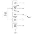
도 1은 종래의 일반적인 발전 시스템의 구성도이다.1 is a block diagram of a conventional general power generation system.
도 1을 참조하면, 종래의 발전 시스템(10)의 경우 발전장치(11)에서 발전된 DC 전력을 전력변환장치(12)에서 AC 전력으로 변환하여 고객인 다수의 부하(13)로 공급한다. 각 부하(13)에서 사용되는 부하량은 계측장치(14)에서 계측한다. 만약, 이와 같이 발전된 전력이 부족한 경우에는 외부의 전력회사로부터 전력을 공급받아 사용할 수 있다.Referring to FIG. 1, in the case of the conventional power generation system 10, DC power generated by the power generator 11 is converted into AC power by the power converter 12 and supplied to a plurality of loads 13 as customers. The load amount used in each load 13 is measured by the measuring device 14. If the generated power is insufficient, power may be supplied from an external power company.
이때, 전력변환장치(12) 및 계측장치(14)는 내부에 통신장치를 구비하고 있어 두 장치(12,14) 간에는 전력선 통신 또는 무선통신 방법을 이용하여 데이터를 송수신한다. 즉, 계측장치(14)는 내부의 통신장치를 이용하여 전력변환장치(12)와의 통신을 수행하여 전력변환장치(12)로부터 발전량 정보를 수신한 후, 그 수신된 발전량 정보 및 자신이 계측한 부하량 정보를 사용자에게 표시하도록 한다.At this time, the power converter 12 and the measurement device 14 is provided with a communication device therein to transmit and receive data between the two devices (12,14) using a power line communication or a wireless communication method. That is, the measurement device 14 receives power generation information from the power converter 12 by performing communication with the power converter 12 by using an internal communication device, and then measures the received power generation information and the self. Display load information to the user.
그런데, 이러한 종래의 발전 시스템(10)의 경우 전력변환장치(12) 및 계측장치(14) 간의 통신이상 발생시에 사용자는 발전량 및 부하량의 확인이 불가능하다는 문제점이 있다. 또한, 전력변환장치(12) 및 계측장치(14)에 모두 통신장치를 내장하여야 하기 때문에 단가가 상승하는 단점이 있다.However, in the conventional power generation system 10, when a communication error occurs between the power converter 12 and the measurement device 14, the user may not be able to identify the amount of power generated and the load. In addition, since the communication device must be built in both the power converter 12 and the measurement device 14, the unit cost increases.
나아가, 전력변환장치(12)로부터 계측장치(14)로 전달하는 발전량 정보는 DC 성분의 전력을 AC 성분의 전력으로 변환한 데이터이므로 부하(13)에 직접 공급되는 AC 성분의 정확한 발전량 정보가 아니다. 따라서, 종래의 발전 시스템(10)에서는 부하(13)에서 사용하는 정확한 부하량은 알 수 없다는 문제점이 있다. 나아가, 전력변환장치(12)의 성능저하나 다른 불량 요인으로 인해 AC 전력으로의 변환시 변환 손실이 발생할 수 있어 정확한 데이터를 수신할 수 없다는 문제점이 있다.Furthermore, since the power generation information transmitted from the power converter 12 to the measuring device 14 is data obtained by converting the power of the DC component into the power of the AC component, it is not accurate power generation information of the AC component directly supplied to the load 13. . Therefore, in the conventional power generation system 10, there is a problem that the exact load amount used in the load 13 is unknown. Further, there is a problem in that conversion loss may occur when converting to AC power due to a poor performance or other poor factors of the power converter 12, so that accurate data cannot be received.
본 발명은 상기한 종래기술의 문제점을 해결하기 위하여, 발전 시스템에서 전력변환장치와 부하 간의 전력공급선 및 부하와 측정장치 간의 전력선에서 각각 발전량 및 부하량을 정확하게 측정하도록 하는 발전 시스템에서의 발전량 및 부하량 측정장치를 제공하는데 목적이 있다.In order to solve the above problems of the prior art, the generation amount and load measurement in the power generation system to accurately measure the amount of generation and load in the power supply line between the power converter and the load and the power line between the load and the measuring device in the power generation system, respectively The purpose is to provide a device.
또한, 본 발명은 간단한 구조와 저렴한 비용으로 발전 시스템에서의 발전량 및 부하량을 측정하는 발전 시스템에서의 발전량 및 부하량 측정장치를 제공하는데 다른 목적이 있다.In addition, another object of the present invention is to provide a power generation amount and load measurement apparatus in a power generation system for measuring power generation amount and load amount in a power generation system with a simple structure and low cost.
상기 목적을 달성하기 위한 본 발명은,According to an aspect of the present invention,
발전장치에서 생성된 DC 전력을 전력변환장치에서 AC 전력으로 변환하여 부하로 전송하고 상기 부하에서의 전력 사용량을 계량하는 전력량계를 포함하는 발전 시스템에서의 발전량 및 부하량 측정장치에 있어서, 상기 전력변환장치 및 부하 간에 연결된 제1 전력선에서의 전류량을 측정하는 제1 전류측정부; 상기 부하 및 전력량계 간에 연결된 제2 전력선에서의 전류량을 측정하는 제2 전류측정부; 상기 제1 전류측정부에서 측정된 전류량을 이용하여 상기 발전 시스템에서의 발전량을 계산하는 발전량 계산부; 상기 제2 전류측정부에서 측정된 전류량을 이용하여 상기 부하에서의 전력 사용량에 따른 부하량을 계산하는 부하량 계산부; 및 상기 계산된 발전량 및 부하량을 각각 표시하는 표시부; 를 포함하는 발전 시스템에서의 발전량 및 부하량 측정장치를 제공한다.An apparatus for measuring power generation and load in a power generation system, comprising a power meter converting DC power generated by a power generator into AC power in a power converter and transferring the power to a load and metering the amount of power used by the load. And a first current measuring unit measuring an amount of current in the first power line connected between the loads. A second current measuring unit measuring an amount of current in a second power line connected between the load and the electricity meter; A power generation calculator configured to calculate a power generation amount in the power generation system by using the current amount measured by the first current measuring unit; A load amount calculator configured to calculate a load amount according to the power consumption of the load by using the current amount measured by the second current measurer; And a display unit for displaying the calculated power generation amount and load amount, respectively. It provides a power generation and load measurement device in a power generation system including a.
본 발명의 실시 예에서, 이러한 발전량 및 부하량 측정장치는,In an embodiment of the present invention, such a power generation and load measurement device,
상기 제1 및 제2 전력선에서의 전류량을 동시에 측정하는 제3 전류측정부; 상기 제3 전류측정부에서 측정된 각각의 전류량을 이용하여 상기 발전 시스템의 발전량 및 상기 부하에서의 부하량을 계산하는 전력량 계산부; 및 상기 발전량 계산부 및 부하량 계산부에서 각각 계산된 발전량 및 부하량과 상기 전력량 계산부에서 계산된 발전량 및 부하량을 비교하는 비교부; 를 더 포함할 수 있고,A third current measuring unit which simultaneously measures the amount of current in the first and second power lines; A power amount calculation unit calculating a power generation amount of the power generation system and a load amount at the load by using the respective current amounts measured by the third current measuring unit; And a comparison unit comparing the power generation amount and load amount calculated by the power generation amount calculation unit and the load amount calculation unit with the power generation amount and load amount calculated by the power amount calculating unit, respectively. May further include
상기 표시부는 상기 비교부의 비교결과에서 양자의 차이가 미리 설정된 오차범위 내에 있는 경우 상기 발전량 계산부 및 부하량 계산부에서 각각 계산된 발전량 및 부하량을 표시함이 바람직하다.Preferably, the display unit displays power generation amount and load amount respectively calculated by the power generation amount calculation unit and the load amount calculation unit when the difference between the two in the comparison result of the comparison unit is within a preset error range.
여기서, 상기 표시부는 상기 비교부에서의 비교결과 양자의 차이가 상기 오차범위를 벗어나는 경우 알람을 표시할 수 있다.The display unit may display an alarm when a difference between the comparison results of the comparison unit is outside the error range.
여기서, 상기 표시부는 상기 양자의 차이를 보정하여 상기 발전량 및 부하량을 표시할 수도 있다.Here, the display unit may display the power generation amount and the load amount by correcting the difference between the two.
본 발명의 실시 예에서, 상기 제1,2,3 전력변환장치는 각각 변류기(CT)를 포함할 수 있다.In an embodiment of the present disclosure, each of the first, second and third power converters may include a current transformer CT.
본 발명에 의하면, 발전 시스템에서 정확한 발전량 및 부하량 데이터를 획득 할 수 있다.According to the present invention, accurate power generation and load data can be obtained in a power generation system.
또한, 본 발명에 따르면, 발전 시스템에서 부가적인 통신장치 없이 발전량과 부하량을 획득할 수 있으므로 구조가 단순해지고 비용이 절감된다.In addition, according to the present invention, since the power generation amount and load amount can be obtained without additional communication apparatus in the power generation system, the structure is simplified and the cost is reduced.
나아가, 본 발명에 따르면 발전 시스템을 이용하는 경우 발전량 및 부하량 정보를 적시에 확인할 수 있으므로 에너지를 효율적으로 사용할 수 있고, 전력시장 등에서 매수시기를 적절히 판단할 수 있다.Furthermore, according to the present invention, since the power generation system and load quantity information can be checked in a timely manner, energy can be efficiently used, and the purchase time can be appropriately determined in the power market.
이하에서, 본 발명의 바람직한 실시 예가 첨부된 도면들을 참조하여 설명할 것이다. 또한, 본 발명을 설명함에 있어서 관련된 공지 기능 또는 구성에 대한 구체적인 설명이 본 발명의 요지를 불필요하게 흐릴 수 있다고 판단되는 경우에는 그 상세한 설명을 생략할 것이다.Hereinafter, preferred embodiments of the present invention will be described with reference to the accompanying drawings. In the following description, a detailed description of known functions and configurations incorporated herein will be omitted when it may make the subject matter of the present invention rather unclear.
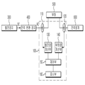
도 2는 본 발명의 일 실시 예에 따른 발전 시스템에서의 발전량 및 부하량 측정장치의 구성도이다.2 is a block diagram of a power generation and load measurement apparatus in a power generation system according to an embodiment of the present invention.
도 2를 참조하면, 본 발명의 일 실시 예에 따른 발전 시스템에서의 발전량 및 부하량 측정장치(100)는 제1 전류측정부(110), 제2 전류측정부(120), 발전량 계산부(130), 부하량 계산부(140), 제어부(150) 및 표시부(160)를 포함한다.2, the power generation amount and load amount measuring device 100 in the power generation system according to an embodiment of the present invention includes a first current measuring unit 110, a second current measuring unit 120, and a power generation calculating unit 130. ), A load calculation unit 140, a controller 150, and a display unit 160.
본 발명의 발전량 및 부하량 측정장치(100)는 발전 시스템에 적용된다. 이러한 발전 시스템은 발전장치(300)에서 생성된 DC 전력을 전력변환장치(400)에서 AC 전력으로 변환하여 적어도 하나의 부하(500)로 전송하고, 이 부하(500)에서의 전력 사용량을 계량하는 전력량계(600)를 포함한다. 이를 위하여 전력변환장치(400)에서 부하(500)로 전력선을 통해 전류를 제공함으로써 전력을 공급하며, 또한 부하(500)에서 전력량계(600) 전력선을 통해 전류를 제공함으로써 전력량계(600)가 부하단에서의 전력 사용량을 계량하도록 한다. Power generation and load measurement device 100 of the present invention is applied to the power generation system. Such a power generation system converts the DC power generated in the
제1 전류측정부(110)는 발전 시스템의 전력변환장치(400)와 부하(500) 간에 연결된 제1 전력선에서의 전류량을 측정한다. 다시 말하면, 전력변환장치(400)에서 DC 전력을 AC 전력으로 변환한 후 부하(500)로 전력을 공급하기 위해 제1 전력선을 통해 전류를 제공하는 경우, 이러한 제1 전력선에 흐르는 전류량을 측정하는 것이다. 일례로 제1 전류측정부(110)는 변류기(CT:Current Transformer)를 포함할 수 있다.The first current measuring unit 110 measures the amount of current in the first power line connected between the
제2 전류측정부(120)는 발전 시스템의 부하(500)와 전력량계(600) 간에 연결된 제2 전력선에서의 전류량을 측정한다. 다시 말하면, 부하(500)에서의 전력 사용량을 계량하기 위해 부하(500)에서 제2 전력선을 통해 전력량계(600)로 전류를 제공하는 경우, 이러한 제2 전력선에 흐르는 전류량을 측정하는 것이다. 일례로 제2 전류측정부(120)는 변류기(CT:Current Transformer)를 포함할 수 있다.The second current measuring unit 120 measures the amount of current in the second power line connected between the
발전량 계산부(130)는 제1 전류측정부(110)에서 측정된 전류량을 이용하여 발전 시스템에서 발전한 전력의 발전량을 계산한다. 일례로 발전량은 부하(500)의 양단에 걸리는 전압과 제1 전류측정부(110)에서 측정된 전류량의 곱으로 계산될 수 있다.The generation amount calculator 130 calculates the amount of power generated in the power generation system using the amount of current measured by the first current measuring unit 110. For example, the amount of power generated may be calculated as the product of the voltage across the
부하량 계산부(140)는 제2 전류측정부(120)에서 측정된 전류량을 이용하여 부하(500)에서의 전력 사용량에 따른 부하량을 계산한다. 일례로 이러한 부하량은 부하(500)의 양단에 걸리는 전압과 제2 전류측정부(120)에서 측정된 전류량의 곱으로 계산될 수 있다. 이때, 상기한 부하량은 부하단에서의 전력 사용량을 의미한다.The load calculator 140 calculates a load amount according to the power consumption of the
제어부(150)는 본 발명의 발전량 및 부하량 측정장치(100)의 전반적인 동작을 제어한다. 특히, 제어부(150)는 발전량 계산부(130) 및 부하량 계산부(140)에서 각각 계산된 발전량 및 부하량을 표시부(160)에서 표시되도록 제어한다. The controller 150 controls the overall operation of the power generation and load measurement apparatus 100 of the present invention. In particular, the controller 150 controls the display unit 160 to display the power generation amount and the load amount calculated by the power generation amount calculation unit 130 and the load amount calculation unit 140, respectively.
표시부(160)는 제어부(150)의 제어신호에 의하여 발전량 계산부(130) 및 부하량 계산부(140)에서 각각 계산된 발전량 및 부하량을 표시한다. 예컨대, 이러한 표시부(160)는 발전량 및 부하량을 사용자(고객)가 쉽게 확인할 수 있도록 시각적 또는 청각적으로 표시할 수 있다.The display unit 160 displays the power generation amount and the load amount respectively calculated by the power generation amount calculation unit 130 and the load amount calculation unit 140 according to the control signal of the controller 150. For example, the display unit 160 may display the power generation amount and the load amount visually or acoustically so that a user (customer) can easily check.
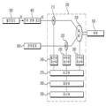
도 3은 본 발명의 다른 실시 예에 따른 발전 시스템에서의 발전량 및 부하량 측정장치의 구성도이다.3 is a block diagram of a power generation and load measurement apparatus in a power generation system according to another embodiment of the present invention.
도 3을 참조하면, 본 발명의 다른 실시 예에 따른 발전 시스템에서의 발전량 및 부하량 측정장치(200)는 제1 전류측정부(210), 제2 전류측정부(220), 제3 전류측정부(230), 발전량 계산부(240), 부하량 계산부(250), 전력량 계산부(260), 비교부(270), 제어부(280) 및 표시부(290)를 포함하여 구성된다. 본 발명의 다른 실시 예에 따른 발전량 및 부하량 측정장치(200)도 상술한 바와 같이 발전 시스템에 적용된다. Referring to FIG. 3, the power generation amount and load
제1 전류측정부(210)는 발전 시스템의 전력변환장치(400)와 부하(500) 간에 연결된 제1 전력선에서의 전류량을 측정하고, 제2 전류측정부(220)는 발전 시스템의 부하(500)와 전력량계(600) 간에 연결된 제2 전력선에서의 전류량을 측정한다. 일례로 제1 및 제2 전류측정부(210,220)는 변류기(CT)를 포함할 수 있다.The first
제3 전류측정부(230)는 상기한 제1 및 제2 전력선에서의 전류량을 동시에 측정한다. 다시 말하면, 발전 시스템의 전력변환장치(400)에서 DC 전력을 AC 전력으로 변환한 후 부하(500)로 전력을 공급하기 위해 제1 전력선을 통해 전류를 제공하는 경우와, 부하(500)에서의 전력 사용량을 계량하기 위해 부하(500)에서 제2 전력선을 통해 전력량계(600)로 전류를 제공하는 경우에, 이러한 제1 전력선 및 제2 전력선에 각각 전류량을 동시에 측정하는 것이다. 일례로, 제3 전류측정부(230)도 변류기(CT)를 포함할 수 있다.The third
발전량 계산부(240)는 제1 전류측정부(210)에서 측정된 전류량을 이용하여 발전 시스템에서 발전한 전력의 발전량을 계산하고, 부하량 계산부(250)는 제2 전류측정부(220)에서 측정된 전류량을 이용하여 부하(500)에서의 전력 사용량에 따른 부하량을 계산한다. The
전력량 계산부(260)는 제3 전류측정부(230)에서 측정된 제1 및 제2 전력선에서의 각 전류량을 이용하여 발전 시스템에서의 발전량 및 부하에서의 부하량을 동시에 계산한다. The
비교부(270)는 발전량 계산부(240) 및 부하량 계산부(250)에서 각각 계산된 발전량 및 부하량과, 전력량 계산부(260)에서 각각 계산된 발전량 및 부하량을 비 교한다. 이는 동일한 제1 및 제2 전력선에 대하여 발전량 계산부(240) 및 부하량 계산부(250)에서 각각 계산된 발전량 및 부하량과, 전력량 계산부(260)에서 각각 계산된 발전량 및 부하량을 서로 비교하기 위한 것이다. 특히, 이는 제1 및 제2 전류측정부(210,220)에서 측정한 발전량 및 부하량이 정확하게 측정되었는지를 제3 전류측정부(230)에서 측정한 발전량 및 부하량으로 확인하기 위한 것이다. The
제어부(280)는 발전량 및 부하량 측정장치(200)의 전반적인 동작을 제어 및 관리한다. 특히, 제어부(280)는 발전량 계산부(240) 및 부하량 계산부(250)에서 각각 계산된 발전량 및 부하량을 표시부(290)에서 표시되도록 제어한다. The
표시부(290)는 제어부(280)의 제어신호에 의하여 발전량 계산부(240) 및 부하량 계산부(250)에서 각각 계산된 발전량 및 부하량을 표시한다. The
특히, 이러한 표시부(290)는 비교부(270)의 비교결과에서 양자, 즉 발전량 계산부(240) 및 부하량 계산부(250)에서 각각 계산된 발전량 및 부하량과, 전력량 계산부(260)에서 각각 계산된 발전량 및 부하량 간에 차이가 미리 설정된 오차범위 내에 있는 경우 발전량 계산부(240) 및 부하량 계산부(250)에서 각각 계산된 발전량 및 부하량을 표시한다. In particular, the
또한, 이러한 표시부(290)는 비교부(270)의 비교결과에서 양자에 차이가 발생할 경우 그 차이를 보정한 후 발전량 계산부(240) 및 부하량 계산부(250)에서 각각 계산된 발전량 및 부하량을 표시할 수도 있다.In addition, the
나아가, 이러한 표시부(290)는 비교부(270)에서의 비교결과 양자의 차이가 미리 설정된 오차범위를 벗어나는 경우 알람을 표시할 수도 있다.In addition, the
이상에서 설명한 본 발명은 바람직한 실시 예들을 통하여 상세하게 설명되었지만, 본 발명은 이러한 실시 예들의 내용에 한정되는 것이 아님을 밝혀둔다. 본 발명이 속하는 기술 분야에서 통상의 지식을 가진 자라면, 비록 실시 예에 제시되지 않았지만 첨부된 청구항의 기재 범위 내에서 다양한 본 발명에 대한 모조나 개량이 가능하며, 이들 모두 본 발명의 기술적 범위에 속함은 너무나 자명하다 할 것이다. 따라서, 본 발명의 진정한 기술적 보호 범위는 첨부된 특허청구범위의 기술적 사상에 의해 정해져야 할 것이다.While the invention has been shown and described with reference to certain preferred embodiments thereof, it is to be understood that the invention is not limited to the disclosed embodiments. Those skilled in the art will appreciate that various modifications, additions and substitutions are possible, without departing from the scope of the appended claims, The genius will be so self-evident. Accordingly, the true scope of the present invention should be determined by the technical idea of the appended claims.
최근 에너지 문제가 사회적 이슈로 떠오르면서 신재생 에너지 발전 시스템에 대한 관심이 높아지고 있다. 이러한 발전 시스템은 태양광, 풍력 등 무한의 자원을 이용하기 때문에 기업뿐만 아니라 가정에서도 매우 유용하게 이용하고 있다. 또한, 이러한 발전 시스템에서 발전된 전력을 축전지에 저장해 두었다가 필요에 따라 사용량을 조절할 수 있고, 전력시장이 형성되는 경우 전력을 매도할 수 있으므로 경제적으로 이득을 얻을 수 있다. Recently, as energy issues have emerged as social issues, interest in renewable energy generation systems is increasing. These power generation systems use infinite resources such as solar and wind power, which is very useful not only for companies but also for homes. In addition, the power generated in the power generation system can be stored in the storage battery, and the amount of use can be adjusted as needed, and if the power market is formed, the power can be sold to obtain economic benefits.
이와 같이 발전된 에너지를 효율적, 경제적으로 이용하기 위해서는 발전 시스템에 생성된 전력의 발전량 및 부하에서 사용하는 전력의 부하량을 정확하게 측정하는 것이 무엇보다도 중요하다. In order to use the generated energy efficiently and economically, it is most important to accurately measure the amount of power generated in the power generation system and the load of the power used by the load.
이러한 측면에서 볼 때, 본 발명은 발전 시스템에서 부하에 전후로 연결된 전력선에서 발전량과 부하량을 측정하므로 정확한 데이터를 얻을 수 있다는 장점이 있기 때문에 가정이나 대규모 공장 등에 매우 유용하게 이용될 수 있다. In view of this, the present invention can be very useful for homes and large factories, because the present invention has the advantage of obtaining accurate data because it measures the amount of power generation and load on the power line connected to the load in the power generation system.
또한, 전력을 공급하는 전력회사나 전력을 사용하는 수요가 입장에서 정확한 발전량 및 부하량을 이용하여 요금 등을 측정하는 것이 중요하므로 전력, 송배전 등의 분야에서 매우 유용하게 이용될 수 있을 것이다.In addition, since it is important to measure the charge using the exact amount of generation and load from the power company that supplies power or demand for power, it may be very useful in fields such as power and transmission and distribution.
도 1은 종래의 일반적인 발전 시스템의 구성도이다.1 is a block diagram of a conventional general power generation system.
도 2는 본 발명의 일 실시 예에 따른 발전 시스템에서의 발전량 및 부하량 측정장치의 구성도이다.2 is a block diagram of a power generation and load measurement apparatus in a power generation system according to an embodiment of the present invention.
도 3은 본 발명의 다른 실시 예에 따른 발전 시스템에서의 발전량 및 부하량 측정장치의 구성도이다.3 is a block diagram of a power generation and load measurement apparatus in a power generation system according to another embodiment of the present invention.
* 도면의 주요 부분에 대한 부호의 설명 * Explanation of symbols on the main parts of the drawings
110,210 : 제1 전류측정부 120,220 : 제2 전류측정부110,210: first current measuring unit 120,220: second current measuring unit
130,240 : 발전량 계산부 140,250 : 부하량 계산부130,240: power generation calculator 140,250: load calculation unit
150,280 : 제어부 160,290 : 표시부150,280 control unit 160,290 display unit
230: 제3 전류측정부 260 : 전력량 계산부230: third current measurement unit 260: power amount calculation unit
300 : 발전장치 400 : 전력변환장치300: power generator 400: power converter
500 : 부하 600 : 전력량계500: load 600: power meter
Claims (6)
Priority Applications (2)
| Application Number | Priority Date | Filing Date | Title |
|---|---|---|---|
| KR1020090120139A KR101254846B1 (en) | 2009-12-04 | 2009-12-04 | Apparatus for measuring generation power and load power for power generation system |
| JP2010267941A JP5243516B2 (en) | 2009-12-04 | 2010-12-01 | Power generation amount and load amount measuring device in power generation system |
Applications Claiming Priority (1)
| Application Number | Priority Date | Filing Date | Title |
|---|---|---|---|
| KR1020090120139A KR101254846B1 (en) | 2009-12-04 | 2009-12-04 | Apparatus for measuring generation power and load power for power generation system |
Publications (2)
| Publication Number | Publication Date |
|---|---|
| KR20110063184A KR20110063184A (en) | 2011-06-10 |
| KR101254846B1 true KR101254846B1 (en) | 2013-04-15 |
Family
ID=44285074
Family Applications (1)
| Application Number | Title | Priority Date | Filing Date |
|---|---|---|---|
| KR1020090120139A KR101254846B1 (en) | 2009-12-04 | 2009-12-04 | Apparatus for measuring generation power and load power for power generation system |
Country Status (2)
| Country | Link |
|---|---|
| JP (1) | JP5243516B2 (en) |
| KR (1) | KR101254846B1 (en) |
Families Citing this family (5)
| Publication number | Priority date | Publication date | Assignee | Title |
|---|---|---|---|---|
| KR101290290B1 (en) * | 2011-11-24 | 2013-07-26 | 한국해양대학교 산학협력단 | Energy management system and method for ship |
| NO334364B1 (en) * | 2012-05-03 | 2014-02-17 | Kongsberg Maritime As | PREDICTIVE CONTROL SYSTEM. |
| KR101963445B1 (en) * | 2015-04-02 | 2019-07-31 | 엘에스산전 주식회사 | Power metering system and method, and system for load power monitoring |
| KR102032406B1 (en) * | 2017-12-29 | 2019-10-15 | 주식회사 에이치엔에스솔루션 | System and Method for Disaster Alarm and Monitoring |
| KR101945501B1 (en) * | 2018-05-23 | 2019-02-08 | 주식회사 광명전기 | Control system and method for providing electric power using solar energy generation and energy storage system |
Citations (2)
| Publication number | Priority date | Publication date | Assignee | Title |
|---|---|---|---|---|
| JPH0764658A (en) * | 1993-08-26 | 1995-03-10 | Hitachi Ltd | Power conversion system |
| JP2006351418A (en) | 2005-06-17 | 2006-12-28 | Matsushita Electric Ind Co Ltd | Power management system and its managing method |
Family Cites Families (7)
| Publication number | Priority date | Publication date | Assignee | Title |
|---|---|---|---|---|
| JP3233521B2 (en) * | 1993-11-25 | 2001-11-26 | シャープ株式会社 | Grid-connected inverse converter |
| JPH10201106A (en) * | 1997-01-07 | 1998-07-31 | Yokogawa M & C Kk | Photovoltaic power generation monitor system |
| JP2002098720A (en) * | 2000-09-26 | 2002-04-05 | Sekisui Chem Co Ltd | Power monitoring system in power supply system |
| JP2002139527A (en) * | 2000-10-31 | 2002-05-17 | Canon Inc | Photovoltaic power generating system and its control method |
| JP2002296307A (en) * | 2001-03-29 | 2002-10-09 | Sekisui Chem Co Ltd | Electric power monitoring device |
| JP2006115622A (en) * | 2004-10-15 | 2006-04-27 | Hanshin Electric Co Ltd | Working power monitoring method and working power monitoring system |
| JP2009182661A (en) * | 2008-01-30 | 2009-08-13 | Kyocera Corp | Communication display |
-
2009
- 2009-12-04 KR KR1020090120139A patent/KR101254846B1/en active IP Right Grant
-
2010
- 2010-12-01 JP JP2010267941A patent/JP5243516B2/en active Active
Patent Citations (2)
| Publication number | Priority date | Publication date | Assignee | Title |
|---|---|---|---|---|
| JPH0764658A (en) * | 1993-08-26 | 1995-03-10 | Hitachi Ltd | Power conversion system |
| JP2006351418A (en) | 2005-06-17 | 2006-12-28 | Matsushita Electric Ind Co Ltd | Power management system and its managing method |
Also Published As
| Publication number | Publication date |
|---|---|
| JP5243516B2 (en) | 2013-07-24 |
| KR20110063184A (en) | 2011-06-10 |
| JP2011120460A (en) | 2011-06-16 |
Similar Documents
| Publication | Publication Date | Title |
|---|---|---|
| JP5644774B2 (en) | Power measurement system, power measurement method, and information processing apparatus | |
| US7584066B2 (en) | Method for determining power flow in an electrical distribution system | |
| Selvam et al. | Advanced metering infrastructure for smart grid applications | |
| JP2006217742A (en) | Voltage distribution calculation device of power distribution system, inter-zone load calculation device, and its method | |
| US20130335062A1 (en) | Power Monitoring System and Method | |
| US20120239959A1 (en) | Power consumption measurement system, outlet device, control device, measuring device, and power consumption measuring method | |
| KR101254846B1 (en) | Apparatus for measuring generation power and load power for power generation system | |
| JP6209951B2 (en) | Transformer connection phase determination device, method, and program | |
| RU2635849C2 (en) | Device and method of voltage and power determination of every phase in medium voltage network | |
| JP2013044752A (en) | Phase identification system and method | |
| WO2017071614A1 (en) | Method for operating energy consumption metering system and energy consumption metering system | |
| US20170292999A1 (en) | Transformer monitoring and data analysis systems and methods | |
| KR20130070132A (en) | A sysyem for monitoring solar power generation | |
| Weniger et al. | Emerging performance issues of photovoltaic battery systems | |
| WO2017145461A1 (en) | Power transmission route state detection device, power transmission route state detection system, power transmission route state detection method, power transmission route state detection program and power conversion device | |
| JP5427007B2 (en) | Power monitoring system | |
| JP2014059245A (en) | Electric power display device | |
| KR102352938B1 (en) | Transformer load monitoring system using metering of dcu | |
| JP2015139322A (en) | power network system | |
| KR101719953B1 (en) | Apparatus for monitoring electric energy | |
| WO2008095277A1 (en) | Hybrid renewable power monitor and data logger | |
| Qin et al. | Power system reliability based on voltage weakest bus identification | |
| EP3575805B1 (en) | Dc substation and method for detecting an electrical energy flow in said substation | |
| Singh et al. | Network controlled distributed energy management system for smart cities | |
| CN112379176A (en) | Transformer loss acquisition system and method |
Legal Events
| Date | Code | Title | Description |
|---|---|---|---|
| A201 | Request for examination | ||
| E701 | Decision to grant or registration of patent right | ||
| GRNT | Written decision to grant | ||
| FPAY | Annual fee payment |
Payment date: 20170403 Year of fee payment: 5 |
|
| FPAY | Annual fee payment |
Payment date: 20180403 Year of fee payment: 6 |
|
| FPAY | Annual fee payment |
Payment date: 20190401 Year of fee payment: 7 |