KR101245296B1 - Electrically responsive device - Google Patents
Electrically responsive device Download PDFInfo
- Publication number
- KR101245296B1 KR101245296B1 KR1020077022508A KR20077022508A KR101245296B1 KR 101245296 B1 KR101245296 B1 KR 101245296B1 KR 1020077022508 A KR1020077022508 A KR 1020077022508A KR 20077022508 A KR20077022508 A KR 20077022508A KR 101245296 B1 KR101245296 B1 KR 101245296B1
- Authority
- KR
- South Korea
- Prior art keywords
- electrical response
- delete delete
- electrode material
- electrode
- substrate
- Prior art date
Links
- 239000000463 material Substances 0.000 claims abstract description 246
- 230000004044 response Effects 0.000 claims abstract description 233
- 239000007772 electrode material Substances 0.000 claims abstract description 123
- 239000000758 substrate Substances 0.000 claims abstract description 79
- 239000011263 electroactive material Substances 0.000 claims abstract description 21
- 238000000034 method Methods 0.000 claims description 50
- 239000012530 fluid Substances 0.000 claims description 36
- 239000002131 composite material Substances 0.000 claims description 20
- 239000000523 sample Substances 0.000 claims description 20
- 230000008859 change Effects 0.000 claims description 17
- 238000003556 assay Methods 0.000 claims description 10
- 238000001514 detection method Methods 0.000 claims description 10
- 230000033001 locomotion Effects 0.000 claims description 10
- 239000000126 substance Substances 0.000 claims description 10
- 239000000945 filler Substances 0.000 claims description 9
- 239000002245 particle Substances 0.000 claims description 9
- 230000002596 correlated effect Effects 0.000 claims description 7
- 239000012491 analyte Substances 0.000 claims description 6
- 239000000538 analytical sample Substances 0.000 claims description 6
- 239000012620 biological material Substances 0.000 claims description 5
- 238000004458 analytical method Methods 0.000 claims description 3
- 230000000737 periodic effect Effects 0.000 claims description 3
- 238000012806 monitoring device Methods 0.000 claims description 2
- 238000012544 monitoring process Methods 0.000 claims description 2
- 238000004519 manufacturing process Methods 0.000 abstract description 18
- 238000005530 etching Methods 0.000 abstract description 5
- 230000008021 deposition Effects 0.000 abstract description 4
- 239000012528 membrane Substances 0.000 description 46
- 239000010410 layer Substances 0.000 description 24
- 239000007788 liquid Substances 0.000 description 14
- 230000006870 function Effects 0.000 description 12
- 230000000875 corresponding effect Effects 0.000 description 10
- 239000000725 suspension Substances 0.000 description 10
- 238000012546 transfer Methods 0.000 description 10
- 238000010897 surface acoustic wave method Methods 0.000 description 8
- 108091027981 Response element Proteins 0.000 description 7
- 230000005284 excitation Effects 0.000 description 7
- 230000008569 process Effects 0.000 description 7
- 230000005540 biological transmission Effects 0.000 description 6
- 238000002474 experimental method Methods 0.000 description 6
- 238000000151 deposition Methods 0.000 description 5
- 229910052751 metal Inorganic materials 0.000 description 5
- 239000002184 metal Substances 0.000 description 5
- 238000012545 processing Methods 0.000 description 5
- XUIMIQQOPSSXEZ-UHFFFAOYSA-N Silicon Chemical compound [Si] XUIMIQQOPSSXEZ-UHFFFAOYSA-N 0.000 description 4
- 229910010293 ceramic material Inorganic materials 0.000 description 4
- PMHQVHHXPFUNSP-UHFFFAOYSA-M copper(1+);methylsulfanylmethane;bromide Chemical compound Br[Cu].CSC PMHQVHHXPFUNSP-UHFFFAOYSA-M 0.000 description 4
- 230000005574 cross-species transmission Effects 0.000 description 4
- 238000010586 diagram Methods 0.000 description 4
- LOKCTEFSRHRXRJ-UHFFFAOYSA-I dipotassium trisodium dihydrogen phosphate hydrogen phosphate dichloride Chemical compound P(=O)(O)(O)[O-].[K+].P(=O)(O)([O-])[O-].[Na+].[Na+].[Cl-].[K+].[Cl-].[Na+] LOKCTEFSRHRXRJ-UHFFFAOYSA-I 0.000 description 4
- 238000009826 distribution Methods 0.000 description 4
- 230000004048 modification Effects 0.000 description 4
- 238000012986 modification Methods 0.000 description 4
- 239000002953 phosphate buffered saline Substances 0.000 description 4
- 229910052710 silicon Inorganic materials 0.000 description 4
- 239000010703 silicon Substances 0.000 description 4
- 230000002745 absorbent Effects 0.000 description 3
- 239000002250 absorbent Substances 0.000 description 3
- 230000003321 amplification Effects 0.000 description 3
- 230000000694 effects Effects 0.000 description 3
- 239000010408 film Substances 0.000 description 3
- PCHJSUWPFVWCPO-UHFFFAOYSA-N gold Chemical compound [Au] PCHJSUWPFVWCPO-UHFFFAOYSA-N 0.000 description 3
- 239000010931 gold Substances 0.000 description 3
- 229910052737 gold Inorganic materials 0.000 description 3
- 238000003199 nucleic acid amplification method Methods 0.000 description 3
- RTAQQCXQSZGOHL-UHFFFAOYSA-N Titanium Chemical compound [Ti] RTAQQCXQSZGOHL-UHFFFAOYSA-N 0.000 description 2
- XLOMVQKBTHCTTD-UHFFFAOYSA-N Zinc monoxide Chemical compound [Zn]=O XLOMVQKBTHCTTD-UHFFFAOYSA-N 0.000 description 2
- 239000006096 absorbing agent Substances 0.000 description 2
- 239000011324 bead Substances 0.000 description 2
- 230000008901 benefit Effects 0.000 description 2
- 239000003795 chemical substances by application Substances 0.000 description 2
- 230000008878 coupling Effects 0.000 description 2
- 238000010168 coupling process Methods 0.000 description 2
- 238000005859 coupling reaction Methods 0.000 description 2
- 239000013078 crystal Substances 0.000 description 2
- 238000001312 dry etching Methods 0.000 description 2
- 238000010894 electron beam technology Methods 0.000 description 2
- 238000010884 ion-beam technique Methods 0.000 description 2
- 238000000608 laser ablation Methods 0.000 description 2
- 238000010329 laser etching Methods 0.000 description 2
- 229910052451 lead zirconate titanate Inorganic materials 0.000 description 2
- 238000003801 milling Methods 0.000 description 2
- 239000012071 phase Substances 0.000 description 2
- 238000005240 physical vapour deposition Methods 0.000 description 2
- 238000001020 plasma etching Methods 0.000 description 2
- 238000007747 plating Methods 0.000 description 2
- 238000003380 quartz crystal microbalance Methods 0.000 description 2
- 238000005546 reactive sputtering Methods 0.000 description 2
- 238000000926 separation method Methods 0.000 description 2
- VYPSYNLAJGMNEJ-UHFFFAOYSA-N silicon dioxide Inorganic materials O=[Si]=O VYPSYNLAJGMNEJ-UHFFFAOYSA-N 0.000 description 2
- 238000004544 sputter deposition Methods 0.000 description 2
- 239000010936 titanium Substances 0.000 description 2
- 229910052719 titanium Inorganic materials 0.000 description 2
- 238000001039 wet etching Methods 0.000 description 2
- 235000019687 Lamb Nutrition 0.000 description 1
- 229910052581 Si3N4 Inorganic materials 0.000 description 1
- 239000000443 aerosol Substances 0.000 description 1
- NWAIGJYBQQYSPW-UHFFFAOYSA-N azanylidyneindigane Chemical compound [In]#N NWAIGJYBQQYSPW-UHFFFAOYSA-N 0.000 description 1
- 239000000872 buffer Substances 0.000 description 1
- 230000001427 coherent effect Effects 0.000 description 1
- 230000006835 compression Effects 0.000 description 1
- 238000007906 compression Methods 0.000 description 1
- 239000004020 conductor Substances 0.000 description 1
- 238000013016 damping Methods 0.000 description 1
- 238000005137 deposition process Methods 0.000 description 1
- 238000009792 diffusion process Methods 0.000 description 1
- 238000005516 engineering process Methods 0.000 description 1
- 230000002708 enhancing effect Effects 0.000 description 1
- 238000003780 insertion Methods 0.000 description 1
- 230000037431 insertion Effects 0.000 description 1
- 239000011229 interlayer Substances 0.000 description 1
- UGKDIUIOSMUOAW-UHFFFAOYSA-N iron nickel Chemical compound [Fe].[Ni] UGKDIUIOSMUOAW-UHFFFAOYSA-N 0.000 description 1
- 230000001788 irregular Effects 0.000 description 1
- HFGPZNIAWCZYJU-UHFFFAOYSA-N lead zirconate titanate Chemical compound [O-2].[O-2].[O-2].[O-2].[O-2].[Ti+4].[Zr+4].[Pb+2] HFGPZNIAWCZYJU-UHFFFAOYSA-N 0.000 description 1
- 239000007791 liquid phase Substances 0.000 description 1
- 239000012811 non-conductive material Substances 0.000 description 1
- 239000000382 optic material Substances 0.000 description 1
- 230000003287 optical effect Effects 0.000 description 1
- 230000000704 physical effect Effects 0.000 description 1
- 230000010399 physical interaction Effects 0.000 description 1
- 238000005381 potential energy Methods 0.000 description 1
- 239000010453 quartz Substances 0.000 description 1
- 230000009467 reduction Effects 0.000 description 1
- 239000012488 sample solution Substances 0.000 description 1
- 239000004065 semiconductor Substances 0.000 description 1
- HQVNEWCFYHHQES-UHFFFAOYSA-N silicon nitride Chemical compound N12[Si]34N5[Si]62N3[Si]51N64 HQVNEWCFYHHQES-UHFFFAOYSA-N 0.000 description 1
- 229910052814 silicon oxide Inorganic materials 0.000 description 1
- 239000000243 solution Substances 0.000 description 1
- 230000000638 stimulation Effects 0.000 description 1
- 239000013077 target material Substances 0.000 description 1
- 239000010409 thin film Substances 0.000 description 1
- 239000012808 vapor phase Substances 0.000 description 1
- 239000011787 zinc oxide Substances 0.000 description 1
Images


Classifications
-
- H—ELECTRICITY
- H03—ELECTRONIC CIRCUITRY
- H03H—IMPEDANCE NETWORKS, e.g. RESONANT CIRCUITS; RESONATORS
- H03H3/00—Apparatus or processes specially adapted for the manufacture of impedance networks, resonating circuits, resonators
-
- G—PHYSICS
- G01—MEASURING; TESTING
- G01N—INVESTIGATING OR ANALYSING MATERIALS BY DETERMINING THEIR CHEMICAL OR PHYSICAL PROPERTIES
- G01N29/00—Investigating or analysing materials by the use of ultrasonic, sonic or infrasonic waves; Visualisation of the interior of objects by transmitting ultrasonic or sonic waves through the object
- G01N29/02—Analysing fluids
- G01N29/036—Analysing fluids by measuring frequency or resonance of acoustic waves
-
- H—ELECTRICITY
- H03—ELECTRONIC CIRCUITRY
- H03H—IMPEDANCE NETWORKS, e.g. RESONANT CIRCUITS; RESONATORS
- H03H3/00—Apparatus or processes specially adapted for the manufacture of impedance networks, resonating circuits, resonators
- H03H3/007—Apparatus or processes specially adapted for the manufacture of impedance networks, resonating circuits, resonators for the manufacture of electromechanical resonators or networks
- H03H3/02—Apparatus or processes specially adapted for the manufacture of impedance networks, resonating circuits, resonators for the manufacture of electromechanical resonators or networks for the manufacture of piezoelectric or electrostrictive resonators or networks
- H03H3/04—Apparatus or processes specially adapted for the manufacture of impedance networks, resonating circuits, resonators for the manufacture of electromechanical resonators or networks for the manufacture of piezoelectric or electrostrictive resonators or networks for obtaining desired frequency or temperature coefficient
-
- H—ELECTRICITY
- H03—ELECTRONIC CIRCUITRY
- H03H—IMPEDANCE NETWORKS, e.g. RESONANT CIRCUITS; RESONATORS
- H03H3/00—Apparatus or processes specially adapted for the manufacture of impedance networks, resonating circuits, resonators
- H03H3/007—Apparatus or processes specially adapted for the manufacture of impedance networks, resonating circuits, resonators for the manufacture of electromechanical resonators or networks
- H03H3/08—Apparatus or processes specially adapted for the manufacture of impedance networks, resonating circuits, resonators for the manufacture of electromechanical resonators or networks for the manufacture of resonators or networks using surface acoustic waves
- H03H3/10—Apparatus or processes specially adapted for the manufacture of impedance networks, resonating circuits, resonators for the manufacture of electromechanical resonators or networks for the manufacture of resonators or networks using surface acoustic waves for obtaining desired frequency or temperature coefficient
-
- G—PHYSICS
- G01—MEASURING; TESTING
- G01N—INVESTIGATING OR ANALYSING MATERIALS BY DETERMINING THEIR CHEMICAL OR PHYSICAL PROPERTIES
- G01N2291/00—Indexing codes associated with group G01N29/00
- G01N2291/02—Indexing codes associated with the analysed material
- G01N2291/025—Change of phase or condition
- G01N2291/0256—Adsorption, desorption, surface mass change, e.g. on biosensors
-
- G—PHYSICS
- G01—MEASURING; TESTING
- G01N—INVESTIGATING OR ANALYSING MATERIALS BY DETERMINING THEIR CHEMICAL OR PHYSICAL PROPERTIES
- G01N9/00—Investigating density or specific gravity of materials; Analysing materials by determining density or specific gravity
- G01N9/002—Investigating density or specific gravity of materials; Analysing materials by determining density or specific gravity using variation of the resonant frequency of an element vibrating in contact with the material submitted to analysis
Landscapes
- Physics & Mathematics (AREA)
- Acoustics & Sound (AREA)
- Manufacturing & Machinery (AREA)
- Engineering & Computer Science (AREA)
- Chemical & Material Sciences (AREA)
- Analytical Chemistry (AREA)
- Biochemistry (AREA)
- General Health & Medical Sciences (AREA)
- General Physics & Mathematics (AREA)
- Immunology (AREA)
- Pathology (AREA)
- Life Sciences & Earth Sciences (AREA)
- Health & Medical Sciences (AREA)
- Investigating Or Analyzing Materials By The Use Of Electric Means (AREA)
- Micromachines (AREA)
- General Electrical Machinery Utilizing Piezoelectricity, Electrostriction Or Magnetostriction (AREA)
- Surface Acoustic Wave Elements And Circuit Networks Thereof (AREA)
Abstract
전기 응답 디바이스 및 전기 응답 디바이스를 제조하는 방법은 전기 응답 재료(예컨대, 전기활성 재료)를 기판 재료의 표면의 적어도 일부분 상에 적용하는 것 및 전극 재료를 전기 응답 재료의 표면의 적어도 일부분 상에 적용하는 것을 포함한다. 전극 재료의 적어도 하나의 영역이 선택적으로 제거되어, 전기 응답 재료를 노출시킨다. 상기 전극 재료의 상기 적어도 하나의 영역에 대응하는 영역에서 상기 전기 응답 재료의 적어도 일부가 선택적으로 제거된다.The electrical response device and method of making the electrical response device include applying an electrical response material (eg, an electroactive material) onto at least a portion of the surface of the substrate material and applying an electrode material onto at least a portion of the surface of the electrical response material. It involves doing. At least one region of the electrode material is selectively removed to expose the electrical response material. At least a portion of the electrical response material is selectively removed in a region corresponding to the at least one region of the electrode material.
전기 응답 재료, 기판 재료, 표면, 공진 모드, 에칭, 증착 Electrical response material, substrate material, surface, resonance mode, etching, deposition
Description
본 발명은 일반적으로 전기 응답 디바이스 및 전기 응답 디바이스를 제조하는 방법에 관한 것이다.The present invention generally relates to an electrical response device and a method of manufacturing the electrical response device.
전기 응답 디바이스는 전기 신호에 응답하여 출력 신호를 발생하거나 입력 신호에 응답하여 전기 신호를 발생하는 디바이스이다. 입력 신호 및 출력 신호의 일반적인 타입은 전기 신호, 광학 신호, 전자기 신호, 진동 신호 및 열 신호를 포함한다. 공진 디바이스가 전기 응답 디바이스의 한가지 타입이다.An electrical response device is a device that generates an output signal in response to an electrical signal or generates an electrical signal in response to an input signal. Common types of input signals and output signals include electrical signals, optical signals, electromagnetic signals, vibration signals and thermal signals. Resonant devices are one type of electrical response device.
표면 탄성파(SAW: surface acoustic wave) 디바이스, 벌크 탄성파(BAW: bulk acoustic wave) 디바이스, FP/LW(flexural plate/lamb wave) 디바이스 및 석영 결정 미량천칭(QCM: quartz crystal microbalance) 디바이스와 같은 공진 디바이스들은 실질적으로 수정과 같은 모놀리식(monolithic) 재료로 제조되거나, 전기활성 재료(예컨대, 산화 아연, PZT(Lead Zirconate Titanate), 질화 알루미늄, 질화 인듐 및 솔-젤(Sol-Gel) 피에조 세라믹 재료와 같은 압전 재료)의 균일한 박막을 다른 미세가공가능 재료(예컨대, 실리콘, 산화 실리콘, 질화 실리콘 및 니켈 철)와 함께 포함하는 층구조 재료로 제조된다. 이들 공진 디바이스는 우선적으로 적절한 재료로 코팅되거나 적절한 환경에서 패키징될 때 예컨대, 전기 필터(예컨 대, 수동), 기상(gas phase) 검출기 및 액상(liquid phase) 센서로서 사용된다.Resonant devices such as surface acoustic wave (SAW) devices, bulk acoustic wave (BAW) devices, flexural plate / lamb wave (FP / LW) devices, and quartz crystal microbalance (QCM) devices They are substantially made of monolithic materials such as quartz, or electroactive materials such as zinc oxide, lead zirconate titanate (PZT), aluminum nitride, indium nitride and sol-gel piezo ceramic materials. And a homogeneous thin film of piezoelectric material such as, together with other micromachinable materials (eg, silicon, silicon oxide, silicon nitride and nickel iron). These resonant devices are primarily used as, for example, electrical filters (eg, passive), gas phase detectors and liquid phase sensors when coated with suitable materials or packaged in suitable environments.
전기 필터로서, 공진 디바이스는 공진 에너지를 전달하고, 디바이스의 통과 대역 밖의 신호를 필터링하는데 사용된다. 전기 필터(예컨대, SAW 디바이스 및 FBAR(film bulk acoustic resonator) 디바이스)는 일반적으로 삽입(insertion), 전송(transmission) 및 반사율(reflectance) 특성에 의해 특징지어진다. 공진 동작의 높은 전송 특성, 분리된 좁은 대역 특성 및 안정된 특성은 유선 신호 및 무선 신호를 변조 및 복조하는데 사용되는 필터의 바람직한 특성들이다. 정의되고 안정된 좁은 통과 대역 필터 특성은 주어진 대역폭 내에 보다 많은 반송파 주파수들을 팩킹하는 것을 가능하게 한다.As an electrical filter, a resonant device delivers resonant energy and is used to filter signals outside the pass band of the device. Electrical filters (eg SAW devices and film bulk acoustic resonator (FBAR) devices) are generally characterized by insertion, transmission and reflectance properties. The high transmission characteristics, separate narrow band characteristics and stable characteristics of the resonant operation are desirable characteristics of the filters used to modulate and demodulate wired and wireless signals. Defined and stable narrow passband filter characteristics make it possible to pack more carrier frequencies within a given bandwidth.
또한, 공진 디바이스들은 때때로 기상 및 액상 샘플 내의 각종 측정량(measurand)(예컨대, 화학적 또는 생물학적 측정량)의 존재 및 양을 결정하는데 사용된다. 공진 센서들은 예컨대, 에어로졸(aerosol) 내의 화학 증기 및 생물학적 물질의 존재 및 크기, 액체의 벌크 특성(예컨대, 밀도, 점도 및 음속) 및 용액 내의 분석 시료(analyte)의 농도를 결정하는데 사용될 수도 있다.In addition, resonant devices are sometimes used to determine the presence and amount of various measurands (eg chemical or biological measurands) in gaseous and liquid samples. Resonant sensors may be used, for example, to determine the presence and size of chemical vapors and biological materials in aerosols, the bulk properties of liquids (eg, density, viscosity and sound velocity) and the concentration of analytes in solution.
기상 동작에서, 공진 디바이스의 표면은 일반적으로, 공진 디바이스의 표면 위를 지나가는 특정 기상 제품과 선택적으로 상호 작용하고 그 특정 기상 제품과 바인딩(binding)되는 흡수성 재료로 코팅된다. 흡수성 재료에 바인딩되는 기상 제품은 공진 디바이스의 질량 부하(mass loading)를 증가시킨다. 질량 부하의 증가는 디바이스의 특성(예컨대, 디바이스의 강성 또는 공진)을 변화시킨다. 공진 디바이스에 의해 생성되는 전기 신호들은 디바이스의 공진의 변화를 반영한다.In vapor phase operation, the surface of the resonant device is generally coated with an absorbent material that selectively interacts with and binds to the particular vapor product passing over the surface of the resonant device. The vapor product bound to the absorbent material increases the mass loading of the resonant device. Increasing the mass load changes the properties of the device (eg, the stiffness or resonance of the device). The electrical signals generated by the resonant device reflect the change in resonance of the device.
액체 동작시, 공진 디바이스의 표면은 액체에 노출된다. 공진 디바이스의 표면은 액체와 상호 작용하고, 후속하여 액체의 공진 디바이스와의 물리적인 상호 작용에 의해 로딩된다. 일부 디바이스들에서, 공진 디바이스의 로딩은 디바이스의 표면 근처에서 액체의 코히어런트(coherent) 진동 압축 및 운동을 통해 일어난다. 공진 디바이스는 로딩이 변함에 따라 변화하는 전기 신호를 생성한다. 액체 운동이 안정되고 진동하면 검출가능 공진 응답이 생기고, 진동하는 운동은 공진 디바이스의 이동 표면의 피크 저장된 잠재 에너지보다 실질적으로 작게 소실된다. 액체 특성의 변화는 공진 디바이스에 의해 발생되는 전기 신호에 기초하여 결정된다.In liquid operation, the surface of the resonant device is exposed to liquid. The surface of the resonant device interacts with the liquid and is subsequently loaded by physical interaction of the liquid with the resonant device. In some devices, loading of the resonant device occurs through coherent vibrational compression and movement of the liquid near the surface of the device. The resonant device generates an electrical signal that changes as the loading changes. When the liquid motion is stable and vibrates, a detectable resonance response is produced, and the vibrating motion is lost substantially less than the peak stored potential energy of the moving surface of the resonant device. The change in liquid properties is determined based on the electrical signal generated by the resonant device.
일반적으로, 공진 디바이스는 다양한 동작 환경(예컨대, 진공, 기상 및 액상)에서 사용될 때 분리된 공진 모드, 좁은 통과 대역, 낮은 손실 및 안정되고 반복가능한 동작 특징을 갖는 것이 바람직하다. (예컨대, 제조 허용 오차로 인한) 디바이스에서의 변동은 분리되지 않은 공진 모드, 넓은 공진 대역, 높은 손실 및 불안정하고 반복 불가능한 동작 특징을 초래하기 쉽다.In general, it is desirable for resonant devices to have separate resonant modes, narrow pass bands, low loss and stable and repeatable operating characteristics when used in a variety of operating environments (eg, vacuum, gaseous, and liquid). Fluctuations in the device (eg, due to manufacturing tolerances) are likely to result in non-separated resonance modes, wide resonance bands, high losses and unstable and non-repeatable operating characteristics.
그러므로, 향상된 전기 응답 디바이스 및 전기 응답 디바이스를 제조하는 방법이 필요하다. Therefore, what is needed is an improved electrical response device and a method of manufacturing the electrical response device.
본 발명은 전기 응답 디바이스 및 전기 응답 디바이스를 제조하는 방법에 특징이 있다. 몇몇 실시예들에서, 본 발명은 공진 디바이스 및 공진 디바이스를 제조하는 방법에 특징이 있다. The present invention is characterized by an electrical response device and a method of manufacturing the electrical response device. In some embodiments, the invention features a resonant device and a method of manufacturing the resonant device.
본 발명은 일 양태에서 공간적으로 변화된 구조적 특성을 가진 디바이스에 특징이 있다. 디바이스의 여기 및/또는 감지 수단은 변화된 구조적 특성과 실질적으로 상관된다. 구조적 특성(예컨대, 강성 및 질량 특성)의 선택적 변화로 바람직한 공진 모드 형상이 얻어진다. 예컨대, 여기 수단을 구조 변화와 상관시킴으로써 바람직한 공진이 선택적으로 여기되어, 바람직한 통과 대역이 얻어진다. 감지 수단을 구조 변화와 상관시킴으로써 바람직한 공진의 선택적 감지가 가능하고, 또한 바람직한 통과 대역이 얻어진다.The invention is in one aspect characterized by a device having a spatially changed structural characteristic. The excitation and / or sensing means of the device are substantially correlated with the changed structural characteristics. Selective changes in structural properties (eg, stiffness and mass properties) yield desirable resonance mode shapes. For example, by correlating the excitation means with the structural change, the desired resonance is selectively excited to obtain the desired pass band. By correlating the sensing means with the structural change, selective sensing of the desired resonance is possible, and the desired passband is obtained.
일 실시예에서, 여기 및 감지 수단을 디바이스의 구조적 특성 변화와 상관시킴으로써 전기 필터(예컨대, SAW(surface acoustic wave) 디바이스 또는 박막 체적 탄성파 공진기(FBAR: film bulk acoustic resonator) 디바이스)는 구조적 수정 없이 달성되는 경우보다 바람직한 통과 대역, 좁은 대역폭 및 낮은 전송 손실을 갖게 된다. 통과 대역은 적어도 하나의 공진 모드를 포함한다.In one embodiment, an electrical filter (eg, a surface acoustic wave (SAW) device or a film bulk acoustic resonator (FBAR) device) is achieved without structural modifications by correlating excitation and sensing means with changes in the structural characteristics of the device. More desirable passband, narrow bandwidth and low transmission loss. The pass band includes at least one resonance mode.
몇몇 실시예들에서, 바람직한 강성 및 질량 변화는 실질적으로 평면인 디바이스에 대해 재료를 선택적으로 제거하거나 추가함으로써 달성된다. 상기 변화는 주기적일 수 있으며, 공간적 주기성이 디바이스의 모드 형상들 중 하나와 일치(또는 실질적으로 일치)하도록 설정된다.In some embodiments, the desired stiffness and mass change is achieved by selectively removing or adding material to the substantially planar device. The change may be periodic and the spatial periodicity is set to coincide (or substantially coincide) with one of the mode shapes of the device.
몇몇 실시예들에서, 디바이스는 변화된 구조적 특성을 가지고 제조되는 재료들의 복합물이다. 몇몇 실시예들에서, 디바이스는 실질적으로 균일한 두께를 갖고 있다. 일 예로서, 디바이스는 디바이스의 제1 재료를 제거한 다음에, 제1 재료를 제거함으로써 노출된 영역을 제1 재료와는 다른 강성을 가진 제2 재료로 채움으로써 균일한 두께로 제조될 수 있다.In some embodiments, the device is a composite of materials manufactured with changed structural properties. In some embodiments, the device has a substantially uniform thickness. As an example, the device may be manufactured to a uniform thickness by removing the first material of the device and then filling the exposed area with a second material having a different stiffness than the first material by removing the first material.
일 실시예에서, 디바이스는 본 발명의 일 실시예에 따른 전극 재료, 전기활성 재료 및 기판 재료를 포함한다. 전기활성 재료는 복합 구조적 특성을 달성하기 위해 기판 재료와 조합되며, 특성(예컨대, 강성 및/또는 질량)은 바람직한 디바이스 특성을 달성하기 위해 디바이스를 따라서 변화된다. 전극 재료를 디바이스의 상당한 영역 상의 전기활성 재료에 적용(예컨대, 증착)함으로써 바람직한 여기 및 감지 모드가 달성된다. 몇몇 실시예들에서, 본 발명의 원리를 포함하는 디바이스를 제조하기 위해 대안적인 재료들을 대신 사용한다. 예컨대, 디바이스를 제조하기 위해 정전기 또는 용량성 여기 및/또는 감지를 허용하는 재료들을 사용할 수 있다.In one embodiment, the device comprises an electrode material, an electroactive material and a substrate material according to one embodiment of the invention. The electroactive material is combined with the substrate material to achieve composite structural properties and the properties (eg, stiffness and / or mass) are varied along the device to achieve the desired device properties. By applying (eg, depositing) the electrode material to an electroactive material on a substantial area of the device, the desired excitation and sensing modes are achieved. In some embodiments, alternative materials are used instead to fabricate a device that incorporates the principles of the present invention. For example, materials that allow for electrostatic or capacitive excitation and / or sensing can be used to fabricate the device.
본 발명은, 다른 양태에서, 전기 응답(예컨대, 공진) 디바이스를 제조하는 방법에 관한 것이다. 이 방법은 전기 응답(예컨대, 전기활성 또는 전기광학) 재료를 기판 재료의 표면의 적어도 일부분 상에 적용하는 것 및 전극 재료를 상기 전기 응답 재료의 표면의 적어도 일부분 상에 적용하는 것을 포함한다. 상기 방법은 또한 상기 전극 재료의 적어도 하나의 영역을 선택적으로 제거하여 상기 전기 응답 재료를 노출시키는 것을 포함한다. 상기 방법은 또한 상기 전극 재료의 적어도 하나의 영역(즉, 전극 재료를 제거함으로써 노출된 영역)에 대응하는 영역에서 전기 응답 재료의 적어도 일부를 선택적으로 제거하는 것을 포함한다.The present invention, in another aspect, relates to a method of manufacturing an electrical response (eg, resonance) device. The method includes applying an electrical response (eg, electroactive or electrooptical) material onto at least a portion of the surface of the substrate material and applying an electrode material onto at least a portion of the surface of the electrical response material. The method also includes selectively removing at least one region of the electrode material to expose the electrical response material. The method also includes selectively removing at least a portion of the electrical response material in a region corresponding to at least one region of the electrode material (ie, the region exposed by removing the electrode material).
몇몇 실시예들에서, 전극 재료의 선택적 제거 및 전기 응답 재료의 제거는 디바이스의 대역 통과 공진 응답(예컨대, 제1 모드보다 큰 모드들)을 실질적으로 향상시킨다.In some embodiments, the selective removal of the electrode material and the removal of the electrical response material substantially enhance the band pass resonance response (eg, modes larger than the first mode) of the device.
몇몇 실시예들에서, 본 발명은 디바이스의 공진 응답 모드를 보강함으로써 디바이스의 공진 응답 모드를 수정하는 방법에 관한 것이다. 몇몇 실시예들에서, 전극 재료의 특별한 패턴이 디바이스의 공진 응답 모드를 보강하기 위해 사용된다. 몇몇 실시예들에서, 상기 전기 응답 재료의 제거는 상기 디바이스의 다른 공진 모드들과 연관된 모드 중첩 및 스필 오버(spillover)를 감소시킴으로써 상기 디바이스의 적어도 하나의 공진 응답 모드를 실질적으로 수정한다.In some embodiments, the present invention is directed to a method of modifying a device's resonance response mode by enhancing the device's resonance response mode. In some embodiments, a special pattern of electrode material is used to enhance the resonant response mode of the device. In some embodiments, the removal of the electrical response material substantially modifies at least one resonant response mode of the device by reducing mode overlap and spillover associated with other resonant modes of the device.
몇몇 실시예들에서, 방법은 또한 상기 전극 재료의 상기 적어도 하나의 영역에 대응하는 영역에서 상기 기판 재료의 적어도 일부를 선택적으로 제거하는 것을 포함할 수 있다. 상기 전극 재료의 제거 및 상기 전기 응답 재료의 제거는 에치 프로세싱(습식 에칭, 건식 에칭, 플라즈마 에칭, 레이저 에칭, 레이저 애블레이션, 이온 빔 밀링 및 전자 빔 에칭 중 하나 이상)을 포함할 수 있다.In some embodiments, the method may also include selectively removing at least a portion of the substrate material in a region corresponding to the at least one region of the electrode material. Removal of the electrode material and removal of the electrical response material may include etch processing (one or more of wet etching, dry etching, plasma etching, laser etching, laser ablation, ion beam milling and electron beam etching).
상기 전극 재료의 제거 및 상기 전기 응답 재료의 제거는 단일 제거 스텝으로 행해질 수 있다(예컨대, 재료를 제거하는 단일 에칭 스텝이 수행됨). 전극 재료의 제거는 전극에 상호 어긋난(interdigitated) 패턴을 생성하는 것을 포함할 수 있다. 상기 전기 응답 재료의 표면상에 전기 응답 재료를 적용하는 것은 상기 전기 응답 재료를 예컨대, 전기 응답 재료의 반응성 스퍼터링에 의해 상기 기판 재료의 표면에 적용하는 것을 포함할 수 있다.Removal of the electrode material and removal of the electrical response material may be done in a single removal step (eg, a single etch step of removing material is performed). Removal of the electrode material may include creating an interdigitated pattern in the electrode. Applying an electrical response material on the surface of the electrical response material may include applying the electrical response material to the surface of the substrate material by, for example, reactive sputtering of the electrical response material.
상기 전기 응답 재료의 표면상에 전극 재료를 적용하는 것은 전극 재료를 상기 전기 응답 재료의 표면에 적용하는 것을 포함할 수 있다. 몇몇 실시예들에서, 전극 재료는 물리적 기상 증착(예컨대, e-빔 증착 플레이팅 또는 스퍼터링)에 의해 적용된다. 몇몇 실시예들에서, 상기 기판 재료와 상기 전기 응답 재료 사이에 전극 재료가 또한 적용된다.Applying an electrode material on the surface of the electrically responding material may include applying an electrode material to the surface of the electrically responding material. In some embodiments, the electrode material is applied by physical vapor deposition (eg, e-beam deposition plating or sputtering). In some embodiments, an electrode material is also applied between the substrate material and the electrical response material.
몇몇 실시예들에서, 상기 전극 재료의 상기 적어도 하나의 영역에 대응하는 상기 영역에서 상기 전기 응답 재료를 선택적으로 제거하는 것은 상기 전극 재료의 상기 적어도 하나의 영역에 대응하는 상기 영역에서 모든 상기 전기 응답 재료를 제거하는 것을 포함한다. 몇몇 실시예들에서, 본 발명의 원리에 따라 여전히 변화된 강성 및/또는 질량 특성을 가지면서 실질적으로 균일한 두께를 갖는 디바이스를 생성하기 위해, 대안적인 재료가 전극 재료 및 전기 응답 재료가 제거된 영역들에 적용된다.In some embodiments, selectively removing the electrical response material in the region corresponding to the at least one region of the electrode material is all the electrical response in the region corresponding to the at least one region of the electrode material. Removing material. In some embodiments, in order to create a device having a substantially uniform thickness while still having varying stiffness and / or mass properties in accordance with the principles of the present invention, the alternative material may be a region where electrode material and electrical response material have been removed. Applies to the
몇몇 실시예들에서, 방법 또한 상기 기판 재료의 일부를 선택적으로 제거하는 것을 포함할 수 있다. 상기 기판 재료의 일부를 선택적으로 제거하는 것은 상기 전기 응답 재료가 상기 기판에 의해 지지되지 않은 적어도 하나의 영역을 갖게 하는 것일 수 있다. 몇몇 실시예들에서, 상기 지지되지 않은 전기 응답 재료는 캔틸레버 전기활성 소자이다. 전기 응답 재료는 예컨대, 전기활성 재료(예컨대, 압전 재료, 피에조 세라믹 재료, 전기 세라믹 재료 또는 단결정 전기활성 재료)를 포함할 수 있다.In some embodiments, the method may also include selectively removing a portion of the substrate material. Selectively removing a portion of the substrate material may be such that the electrically responding material has at least one area not supported by the substrate. In some embodiments, the unsupported electrical response material is a cantilever electroactive device. The electrically responding material may include, for example, an electroactive material (eg, piezoelectric material, piezo ceramic material, electro ceramic material or single crystal electroactive material).
상기 기판, 전기 응답 재료 및 전극 재료의 조합이 집적 회로 패키지에 통합될 수 있다. 상기 방법에 따라 제조된 디바이스는 필터 또는 센서(예컨대, 물리, 생물학적 또는 화학 센서)일 수 있다.The combination of substrate, electrical response material, and electrode material may be integrated into an integrated circuit package. Devices manufactured according to the method may be filters or sensors (eg, physical, biological or chemical sensors).
몇몇 실시예들에서, 충전재가 이전에 선택적으로 제거된 상기 전기 응답 재료의 영역에 적용된다. 상기 충전재는 상기 전기 응답 재료의 강성과 유사하지 않은 강성을 가질 수 있다.In some embodiments, a filler is applied to the area of the electrical response material previously selectively removed. The filler may have a stiffness that is not similar to that of the electrical response material.
본 발명은, 다른 양태에서, 전극 재료를 전기 응답 재료의 표면의 적어도 일부분 상에 적용하는 것을 포함하는, 전기 응답 디바이스(예컨대, 공진 디바이스)를 제조하는 방법에 관한 것이다. 이 방법은 또한 상기 전극 재료의 적어도 하나의 영역을 선택적으로 제거하여 상기 전기 응답 재료를 노출시키는 것을 포함한다. 상기 방법은 또한 상기 디바이스의 적어도 하나의 공진 모드를 실질적으로 수정하기 위해, 상기 전극 재료의 상기 적어도 하나의 영역에 대응하는 영역에서 상기 전기 응답 재료의 적어도 일부를 선택적으로 제거하는 것을 포함한다.The present invention relates, in another aspect, to a method of manufacturing an electrical response device (eg, a resonant device) comprising applying electrode material on at least a portion of a surface of the electrical response material. The method also includes selectively removing at least one region of the electrode material to expose the electrical response material. The method also includes selectively removing at least a portion of the electrical response material in a region corresponding to the at least one region of the electrode material to substantially modify at least one resonance mode of the device.
본 발명은, 다른 양태에서, 전기 응답 디바이스를 제조하는 방법에 관한 것이다. 이 방법은 전기 응답 재료를 기판 재료의 표면에 선택적으로 적용하는 것; 및 상기 디바이스의 적어도 하나의 공진 응답 모드를 실질적으로 수정하기 위해, 전극 재료를 상기 전기 응답 재료의 표면에 선택적으로 적용하는 것을 포함한다.The present invention, in another aspect, relates to a method of manufacturing an electrical response device. The method includes selectively applying an electrical response material to the surface of the substrate material; And selectively applying an electrode material to the surface of the electrical response material to substantially modify at least one resonance response mode of the device.
본 발명은, 다른 양태에서, 전기 응답 디바이스에 특징이 있다. 전기 응답 디바이스는 기판 재료 및 상기 기판상의 적어도 하나의 전기 응답 소자를 포함한다. 전기 응답 디바이스는 또한 상기 적어도 하나의 전기 응답 소자의 표면상의 전극 재료를 포함하고, 상기 전기 응답 소자 및 상기 전극 재료는 상기 디바이스의 적어도 하나의 공진 응답 모드를 수정하도록 구성된다.The present invention, in another aspect, is characterized by an electrical response device. The electrical response device includes a substrate material and at least one electrical response element on the substrate. The electrical response device also includes an electrode material on the surface of the at least one electrical response element, wherein the electrical response element and the electrode material are configured to modify at least one resonance response mode of the device.
본 발명은, 다른 양태에서, 기판 재료 및 상기 기판상의 적어도 하나의 전기 응답 소자를 포함하는 전기 응답 디바이스에 특징이 있다. 상기 전기 응답 디바이스는 또한 상기 적어도 하나의 전기 응답 소자의 표면상의 전극 재료를 포함하고, 상기 전기 응답 소자 및 상기 전극 재료는 상기 디바이스의 다른 공진 모드들과 연관된 모드 중첩 및 스필 오버를 감소시킴으로써 상기 디바이스의 적어도 하나의 공진 응답 모드를 수정하기 위해 상기 기판 층상에 패터닝된다.The invention is characterized in another aspect in an electrical response device comprising a substrate material and at least one electrical response element on the substrate. The electrical response device also includes an electrode material on the surface of the at least one electrical response element, wherein the electrical response element and the electrode material reduce the mode overlap and spill over associated with other resonant modes of the device. Is patterned on the substrate layer to modify at least one resonance response mode.
몇몇 실시예들에서, 상기 전기 응답 재료 및 전극 재료는 적어도 하나의 작동 소자 및 적어도 하나의 감지 소자를 생성하기 위해 패터닝된다. 몇몇 실시예들에서, 상기 전기 응답 재료 및 전극 재료는 적어도 하나의 론칭 소자 및 적어도 하나의 수신기 소자를 생성하기 위해 패터닝된다. 공진 디바이스는 상기 전기 응답 재료와 상기 기판 재료 사이에 전도성(예컨대, 금속) 재료를 포함할 수 있다In some embodiments, the electrical response material and the electrode material are patterned to produce at least one actuating element and at least one sensing element. In some embodiments, the electrical response material and electrode material are patterned to produce at least one launch element and at least one receiver element. The resonant device may comprise a conductive (eg, metal) material between the electrical response material and the substrate material.
본 발명은, 다른 양태에서, 표면을 갖고 평면을 정의하는 기판 재료를 포함하는 전기 응답 디바이스에 특징이 있다. 전기 응답 디바이스는 또한 상기 기판 재료의 표면의 적어도 일부분 상에 있고, 상기 기판 재료의 평면 내에서 두께가 변화하는 전기 응답 재료를 포함한다. 전기 응답 디바이스는 또한 상호 어긋난 패턴 내의 상기 전기 응답 재료의 표면의 부분들 상의 전극 재료를 포함한다.The present invention is characterized in another aspect in an electrical response device comprising a substrate material having a surface and defining a plane. The electrical response device also includes an electrical response material that is on at least a portion of the surface of the substrate material and varies in thickness in the plane of the substrate material. The electrical response device also includes an electrode material on portions of the surface of the electrical response material in the misaligned pattern.
몇몇 실시예들에서, 상기 전극 재료 영역들은 상기 전기 응답 재료의 보다 두꺼운 영역들 상에 위치한다. 몇몇 실시예들에서, 상기 전극 재료 영역들은 상기 전기 응답 재료의 보다 얇은 영역 상에 위치한다.In some embodiments, the electrode material regions are located on thicker regions of the electrical response material. In some embodiments, the electrode material regions are located on a thinner region of the electrical response material.
본 발명은, 다른 양태에서, 전기 응답 디바이스에 특징이 있다. 전기 응답 디바이스는 표면을 갖고 상기 기판 재료의 평면 내에서 두께가 변화하는 기판 재료를 포함한다. 전기 응답 디바이스는 또한 상기 기판 재료의 표면의 적어도 일부분 상의 전기 응답 재료를 포함한다. 전기 응답 디바이스는 또한 상호 어긋난 패턴 내의 상기 전기 응답 재료의 표면의 부분들 상의 전극 재료를 포함한다.The present invention, in another aspect, is characterized by an electrical response device. The electrical response device comprises a substrate material having a surface and varying in thickness in the plane of the substrate material. The electrical response device also includes an electrical response material on at least a portion of the surface of the substrate material. The electrical response device also includes an electrode material on portions of the surface of the electrical response material in the misaligned pattern.
본 발명은, 다른 양태에서, 전기 응답 디바이스를 제조하는 방법에 관한 것이다. 이 방법은 전기 응답 재료를 기판 재료의 표면의 적어도 일부분 상에 적용하는 것을 포함한다. 이 방법은 또한 상기 전기 응답 재료의 적어도 일부를 선택적으로 제거하는 것을 포함한다. 상기 방법은 또한 전극 재료를 상기 전기 응답 재료의 표면의 적어도 일부분 상에 적용하는 것을 포함한다.The present invention, in another aspect, relates to a method of manufacturing an electrical response device. The method includes applying an electrical response material onto at least a portion of the surface of the substrate material. The method also includes selectively removing at least a portion of the electrical response material. The method also includes applying an electrode material on at least a portion of the surface of the electrically response material.
몇몇 실시예들에서, 상기 전극 재료를 적용하는 것은 전기 응답 재료상에 상호 어긋난 전극 패턴을 생성한다. 몇몇 실시예들에서, 상기 전극 재료를 적용하는 것은 전기 응답 재료상에 환형 전극 패턴을 생성한다.In some embodiments, applying the electrode material produces a mutually misaligned electrode pattern on the electrical response material. In some embodiments, applying the electrode material creates an annular electrode pattern on the electrical response material.
본 발명은, 다른 양태에서, 전기 응답 디바이스를 제조하는 방법에 관한 것이다. 이 방법은 제1전극 재료를 기판 재료의 표면의 적어도 일부분 상에 적용하는 것 및 전기 응답 재료를 상기 제1 전극 재료의 표면의 적어도 일부분 상에 적용하는 것을 포함한다. 상기 방법은 또한 제2 전극 재료를 상기 전기 응답 재료의 표면의 적어도 일부분 상에 적용하는 것을 포함한다. 상기 방법은 또한 상기 디바이스의 적어도 하나의 공진 응답 모드를 수정하기 위해, 상기 전기 응답 재료 또는 상기 기판 재료 중 적어도 하나의 재료의 일부를 선택적으로 제거하는 것을 포함한다.The present invention, in another aspect, relates to a method of manufacturing an electrical response device. The method includes applying a first electrode material onto at least a portion of the surface of the substrate material and applying an electrical response material onto at least a portion of the surface of the first electrode material. The method also includes applying a second electrode material on at least a portion of the surface of the electrically responding material. The method also includes selectively removing a portion of at least one of the electrical response material or the substrate material to modify at least one resonance response mode of the device.
본 발명은, 다른 양태에서, 분석 시료의 검출 장치에 특징이 있다. 이 분석 시료의 검출 장치는 유체 채널을 포함한다. 분석 시료의 검출 장치는 또한, 상기 유체 채널의 적어도 하나의 표면의 적어도 일부분을 정의하는 전기 응답 디바이스를 포함한다. 분석 시료의 검출 장치는 또한, 상기 디바이스에 의해 출력되는 적어도 하나의 신호를 감시하는 감시 디바이스를 포함한다. 디바이스는 표면을 갖고 평면을 정의하는 기판 재료를 포함한다. 디바이스는 또한 상기 기판 재료의 표면의 적어도 일부분 상에 있고, 상기 기판 재료의 평면 내에서 두께가 변화하는 전기 응답 재료를 포함한다. 디바이스는 또한 상호 어긋난 패턴 내의 상기 전기 응답 재료의 표면의 부분들 상의 전극 재료를 포함한다.In another aspect, the present invention is characterized by a detection device for analytical sample. The detection device of this analytical sample includes a fluid channel. The apparatus for detecting analyte sample also includes an electrical response device that defines at least a portion of at least one surface of the fluid channel. The detection apparatus of the analysis sample also includes a monitoring device for monitoring at least one signal output by the device. The device includes a substrate material having a surface and defining a plane. The device also includes an electrical response material that is on at least a portion of the surface of the substrate material and that varies in thickness in the plane of the substrate material. The device also includes an electrode material on portions of the surface of the electrically responding material in the misaligned pattern.
본 발명은, 다른 양태에서, 분석 시료의 검출 카트리지에 특징이 있다. 카트리지는 유체 채널 및 상기 유체 채널 내에 위치되거나 상기 유체 채널의 적어도 하나의 표면의 적어도 일부분을 정의하는 전기 응답 디바이스(예컨대, 공진 디바이스)를 포함한다. 상기 전기 응답 디바이스는 표면을 갖고 평면을 정의하는 기판 재료를 포함한다. 전기 응답 디바이스는 또한, 상기 기판 재료의 표면의 적어도 일부분 상에 있고, 상기 기판 재료의 평면 내에서 두께가 변화하는 전기 응답 재료를 포함한다. 전기 응답 디바이스는 또한, 상호 어긋난 패턴 내의 상기 전기 응답 재료의 표면의 부분들 상의 전극 재료를 포함한다.In another aspect, the invention is characterized by a detection cartridge of an analytical sample. The cartridge includes a fluid channel and an electrical response device (eg, a resonant device) positioned within or defining at least a portion of at least one surface of the fluid channel. The electrical response device comprises a substrate material having a surface and defining a plane. The electrical response device also includes an electrical response material that is on at least a portion of the surface of the substrate material and varies in thickness in the plane of the substrate material. The electrical response device also includes an electrode material on portions of the surface of the electrical response material in the misaligned pattern.
본 발명은, 다른 양태에서, 분석 시료의 검출에 사용되는 키트에 특징이 있다. 키트는 유체 채널 및 분석 시료를 상기 디바이스의 표면에 구체적으로 바인딩되는 제1 구성 요소를 갖는 카트리지를 포함한다. 상기 카트리지는 또한, 상기 유체 채널 내에 위치되거나 상기 유체 채널의 적어도 하나의 표면의 적어도 일부분을 정의하는 전기 응답 디바이스(예컨대, 공진 디바이스)를 포함한다. 디바이스는 표면을 갖고 평면을 정의하는 기판 재료를 포함한다. 디바이스는 또한 상기 기판 재료의 표면의 적어도 일부분 상에 있고 상기 기판 재료의 평면 내에서 두께가 변화하는 전기 응답 재료를 포함한다. 다바이스는 또한 상호 어긋난 패턴 내의 상기 전기 응답 재료의 표면의 부분들 상의 전극 재료를 포함한다. 키트는 또한 상기 분석 시료를 구체적으로 바인딩하는 제2 구성 요소를 가진 입자들(예컨대, 자기 비드(magnetic beads))을 포함한다.In another aspect, the invention is characterized by a kit used for detection of analytical sample. The kit includes a cartridge having a first component that specifically binds a fluid channel and an assay sample to the surface of the device. The cartridge also includes an electrical response device (eg, a resonant device) located within the fluid channel or defining at least a portion of at least one surface of the fluid channel. The device includes a substrate material having a surface and defining a plane. The device also includes an electrical response material that is on at least a portion of the surface of the substrate material and whose thickness varies within the plane of the substrate material. The device also includes an electrode material on portions of the surface of the electrically responding material in the misaligned pattern. The kit also includes particles with a second component that specifically binds the assay sample (eg magnetic beads).
본 발명은, 다른 양태에서, 전기 응답 디바이스를 제조하는 방법에 관한 것이다. 상기 방법은 기판 재료의 적어도 일부분 상에 전기 응답 재료를 제공하는 것을 포함한다. 상기 방법은 또한 디바이스의 공진 모드를 분리하기 위해, 상기 전기 응답 재료 또는 상기 기판 재료 중 적어도 하나의 재료의 특성(예컨대, 구조적 특성)을 변화시키는 것을 포함한다.The present invention, in another aspect, relates to a method of manufacturing an electrical response device. The method includes providing an electrical response material on at least a portion of the substrate material. The method also includes changing a characteristic (eg, structural characteristic) of at least one of the electrical response material or the substrate material to separate the resonance mode of the device.
상기 특성을 변화시키는 것은 상기 전기 응답 재료 또는 상기 기판 재료의 일부분 상에서 강성을 변화시키는 것을 포함할 수 있다. 상기 특성을 변화시키는 것은 상기 전기 응답 재료 또는 상기 기판 재료의 일부 상에서 질량의 분포를 변화시키는 것을 포함할 수 있다. 상기 특성을 변화시키는 것은 상기 전기 응답 재료의 표면상의 전극 패턴과 실질적으로 대응하도록 상기 전기 응답 재료의 일부분을 제거하는 것을 포함할 수 있다.Changing the property can include changing the stiffness on the electrical response material or a portion of the substrate material. Changing the property can include changing the distribution of mass on the electrically responsive material or a portion of the substrate material. Changing the property may include removing a portion of the electrical response material to substantially correspond to an electrode pattern on the surface of the electrical response material.
본 발명은, 다른 양태에서, 전기 응답 디바이스에 특징이 있다. 상기 디바이스 기판 재료를 포함한다. 디바이스는 또한 상기 기판의 적어도 일부분 상의 전기 응답 재료를 포함하고, 상기 기판 재료 또는 상기 전기 응답 재료 중 적어도 하나의 재료의 특성은 상기 디바이스의 강성을 변화시킴으로써 상기 디바이스의 공진 모드를 분리하기 위해 변화된다.The present invention, in another aspect, is characterized by an electrical response device. The device substrate material. The device also includes an electrically responsive material on at least a portion of the substrate, and properties of the at least one of the substrate material or the electrically responsive material are varied to isolate the resonant mode of the device by changing the stiffness of the device. .
본 발명은, 다른 양태에서, 전기 응답 디바이스를 제조하는 방법에 관한 것이다. 이 방법은 기판 재료의 표면의 적어도 일부분 상에 전기 응답 재료를 적용하는 것을 포함한다. 이 방법은 또한, 전기 응답 재료의 표면의 적어도 일부분 상에 전극 재료를 적용하는 것을 포함한다. 상기 방법은 또한, 상기 디바이스의 적어도 하나의 공진 응답 모드를 실질적으로 수정하기 위해 상기 디바이스 상에서의 질량 분포를 변화시키기 위하여, 상기 디바이스의 표면의 적어도 일부분 상에 재료를 적용하는 것을 포함한다.The present invention, in another aspect, relates to a method of manufacturing an electrical response device. The method includes applying an electrical response material on at least a portion of the surface of the substrate material. The method also includes applying the electrode material onto at least a portion of the surface of the electrically response material. The method also includes applying a material on at least a portion of the surface of the device to change the mass distribution on the device to substantially modify the at least one resonance response mode of the device.
본 발명은 다른 양태에서, 공간적으로 변화된 구조적 특성을 가진 복합 구조를 포함하는 전기 응답 디바이스에 특징이 있다. 전기 응답 디바이스는 또한 좁고(예컨대, 주파수에 대해) 손실이 낮은(보다 뚜렷한 전달 함수 피크를 가짐) 통과 대역을 생성하기 위해 공간적으로 변화된 특성과 실질적으로 상관되는 상기 구조의 운동을 여기 및 감지하는 수단을 포함한다. 본 발명에 따른 이점은 유체 로딩에 노출된 디바이스 또는 유체 로딩에 노출되지 않은 디바이스에서 달성될 수 있다. In another aspect, the present invention is characterized in an electrical response device comprising a composite structure having spatially changed structural properties. The electrical response device may also be a means for exciting and sensing motion of the structure that is substantially correlated with the spatially changed characteristics to produce a narrow (eg, frequency) and low loss (having a more pronounced transfer function peak) passband. It includes. The advantages according to the invention can be achieved in devices exposed to fluid loading or devices not exposed to fluid loading.
몇몇 실시예들에서, 복합 구조는 전기활성 재료를 포함한다. 몇몇 실시예들에서, 공간적으로 변화된 특성은 상기 구조의 표면을 따라 주기적이다. 몇몇 실시예들에서, 상기 복합 구조는 생물 또는 화학 물질에 바인딩될 수 있다.In some embodiments, the composite structure includes an electroactive material. In some embodiments, the spatially changed property is periodic along the surface of the structure. In some embodiments, the composite structure can be bound to a biological or chemical substance.
본 발명 자체뿐만 아니라 본 발명의 상기한 목적 및 다른 목적, 특징 및 이점은 반드시 일정한 비율로 작성된 것은 아닌 첨부 도면과 함께 이하의 예시적인 설명을 읽을 때 보다 완전하게 이해될 것이다.The foregoing and other objects, features and advantages of the present invention as well as the invention itself will be more fully understood upon reading the following illustrative description in conjunction with the accompanying drawings, which are not necessarily drawn to scale.
도 1A는 전기 응답 디바이스의 개략적인 예시도. 1A is a schematic illustration of an electrical response device.
도 1B는 도 1A의 디바이스의 일부분의 개략적인 예시도.1B is a schematic illustration of a portion of the device of FIG. 1A.
도 2는 본 발명의 일 실시예에 따른 전기 응답 디바이스의 일부분의 개략적인 예시도.2 is a schematic illustration of a portion of an electrical response device in accordance with an embodiment of the present invention.
도 3은 본 발명의 일 실시예에 따른 전기 응답 디바이스를 제조하는 방법의 상이한 단계들의 개략적인 예시도.3 is a schematic illustration of different steps of a method of manufacturing an electrical response device according to an embodiment of the present invention.
도 4는 본 발명의 일 실시예에 따른 전기 응답 디바이스의 일부분의 개략적인 예시도.4 is a schematic illustration of a portion of an electrical response device in accordance with one embodiment of the present invention.
도 5는 본 발명의 일 실시예에 따른 전기 응답 디바이스의 일부분의 개략적인 예시도.5 is a schematic illustration of a portion of an electrical response device in accordance with an embodiment of the present invention.
도 6은 본 발명의 일 실시예에 따른 전극 재료의 패턴의 개략적인 예시도.6 is a schematic illustration of a pattern of electrode material according to one embodiment of the invention.
도 7은 본 발명의 일 실시예에 따른 전극 재료의 패턴의 개략적인 예시도.7 is a schematic illustration of a pattern of electrode material in accordance with one embodiment of the present invention.
도 8은 본 발명의 원리를 포함하는 공진 디바이스 및 본 발명의 원리를 포함하지 않는 공진 디바이스의 전달 함수 크기 대 주파수의 그래픽 표현.8 is a graphical representation of transfer function magnitude versus frequency of a resonant device incorporating the principles of the present invention and a resonant device not incorporating the principles of the present invention.
도 9는 본 발명의 원리를 포함하는 공진 디바이스 및 본 발명의 원리를 포함하지 않는 공진 디바이스의 전달 함수 크기 대 주파수의 그래픽 표현.9 is a graphical representation of transfer function magnitude versus frequency of a resonant device incorporating the principles of the present invention and a resonant device not incorporating the principles of the present invention.
도 1A는 전기 응답 디바이스(100)의 개략적인 예시도이다. 이 실시예에서, 전기 응답 디바이스(100)는 당해 기술 분야에서 알려진 마이크로 제조 기술을 이용하여 기판(108)(예컨대, 실리콘 웨이퍼)으로 구성된 공진 디바이스이다. 본 발명의 범위를 벗어나지 않고 대안적인 제조 방법들이 가능하다. 이 실시예에서, 캐비티(124)가 기판(108) 안으로 에칭되어, 얇은 현수 멤브레인(suspended membrane)(104)이 생성되며, 멤브레인의 길이는 (X 축을 따라) 대략 1.6 mm이고, 폭은 (Z 축을 따라) 0.3 mm이며, 두께는 (Y 축을 따라) 2 μm이다. 전체 기판(108)의 두께는 대략 500μm이며, 따라서 캐비티(124)의 깊이는 기판(108)의 두께보다 약간 작다. 전기 응답 재료(132)(예컨대, 전기활성(electroactive) 재료 또는 전기광학 재료)의 0.5 μm 층이, 도 1B의 확대도에서 디바이스(100)의 영역(120)에 도시된 바와 같이, 멤브레인(104)의 외부 표면(160)(즉, 캐비티(124)의 반대쪽 표면)상에 증착된다. 몇몇 실시예들에서는, 캐비티(124) 대신에 유체 채널(fluid channel)이 사용되며, 유체 채널은 예컨대 유체를 멤브레인(104)에 전달하거나 멤브레인(104)으로부터 멀리 유체를 보낸다.1A is a schematic illustration of the
몇몇 실시예들에서, 전기 응답 디바이스는 복합 구조를 형성하는 다양한 재료들로 제조된다. 전기 응답 디바이스는 또한 복합 구조의 작동 및 복합 구조의 운동의 감지를 가능하게 하는 작동 및 감지 구조를 포함한다. 일 실시예에서, 복합 구조는 도 2의 영역(120)을 포함하는 도 1에 도시된 현수 구조(142)이다.In some embodiments, the electrical response device is made of various materials that form a composite structure. The electrical response device also includes an actuation and sensing structure that enables actuation of the complex structure and sensing of the movement of the complex structure. In one embodiment, the composite structure is the
전기 응답 재료(132)는 예컨대, 전기활성 재료(예컨대, 압전 재료, 피에조 세라믹 재료, 전기세라믹 재료 또는 단결정 전기활성 재료)일 수 있다. 일 실시예 에서, 전기활성 재료는 AlN(질화 알루미늄)이다. 두 세트의 상호 어긋난 금속 전극 재료(140)의 형태인 전극 재료가 전기 응답 재료(132)의 외부 표면(164)상에 증착된다. 몇몇 실시예들에서, 티타늄 및/또는 금이 적합한 전극 재료이다. 일 실시예에서, 100 옹스트롬의 티타늄층이 전극 재료(140)로 사용된다. 몇몇 실시예들에서, 금속(예컨대, 금)의 박층이 전극 재료(140)의 증착 전에 전기활성 재료(132)의 외부 표면(164)상에 증착된다.The
이 실시예에서, 멤브레인(104)을 형성하는 기판(108)은 실리콘이다. 실리콘 멤브레인(104)은 전도성이며, 바람직하게는 고유 저항이 약 0.01 ohm-cm 이하이다. 멤브레인(104)은 하부 전극으로서의 기능을 한다. 필드가 한 세트의 상호 어긋난 전극 재료(140)와 멤브레인(104) 사이에 인가된다. 이 실시예에서, 전극 재료(140)와 멤브레인(104) 사이의 필드는 실질적으로 X- Y 평면 내에 있다. 그러나, 몇몇 실시예들에서 멤브레인(104)은 전도성이 아니거나, 비전도성 재료가 (X-Y 평면에서 보았을 때) 멤브레인 아래에 위치된다. 이들 실시예에서, 별도의 부가적인 전극 재료 리드(lead) 또는 층(도시되지 않음)이 제공되며, 이 리드 또는 층은 상호 어긋난 전극 재료(140)로부터 전기적으로 분리되어 있다. 상기 부가적인 전극 재료는 각 세트의 전극 재료 사이에 위치되며, 필드가 각 세트의 전극 재료와 상기 부가 재료 사이에 인가되어, 예컨대, 전기 응답 재료를 작동시킨다. 이 방식에서, 필드는 실질적으로 X-Z 평면에서 인가된다.In this embodiment, the
예컨대 포집제(capture agent)의 고정(immobilization)을 용이하게 하기 위해 금속(예컨대, 대략 500 옹스트롬의 금)의 층(136)이 멤브레인(104)의 내부 표 면(138)(즉, 캐비티(124)와 마주하는 표면) 상에 증착된다. 예컨대, 유체 샘플 내의 물질을 정량화(quantify)하는데 디바이스(100)를 사용하는 환경에서 생물학적 물질 또는 화학 물질이 상기 층(136)상의 포집제에 바인딩된다. 몇몇 실시예들에서는, 금속층(136)이 사용되지 않는다.For example, to facilitate immobilization of the capture agent, a
동작시, 기기/제어 전자 장치(128)(도 1A 참조)가 현수 멤브레인(104)에서 진동(112)을 발생시키기 위해 시변 전기 신호를 (멤브레인(104)에 대해) 한 세트의 전극 재료(140)에 인가한다. 기기/제어 전자 장치(128)는 또한 멤브레인(104)에 대한 제2 세트의 전극 재료(140)로부터 센서 신호를 수신함으로써 멤브레인(104)의 진동 특성을 감시한다.In operation, the instrument / control electronics 128 (see FIG. 1A) generates a time-varying electrical signal (relative to the membrane 104) to generate a
일 실시예에서, 유체 내에서 현수되는 생물학적 분자들의 존재를 검출하기 위해 여러 유체들이 공진 디바이스의 응용에 이용된다. 기준 공진 응답을 설정하기 위해서 기준 완충 유체가 층(136)에 노출된다. 생물학적 분자들을 함유한 샘플 용액이 디바이스(100)의 층(136)상에서 흐른다. 생물학적 분자들 중 적어도 일부가 층(136)에 바인딩되어, 디바이스(100)의 공진 특성을 변화시킨다. 얼마나 많은 생물학적 물질이 디바이스(100)의 층(136)에 바인딩되어 있는지를 결정하기 위해서, 바인딩된 생물학적 분자들을 가진 디바이스(100)의 공진이 기준 공진과 비교된다.In one embodiment, several fluids are used in the application of the resonant device to detect the presence of biological molecules suspended in the fluid. Reference buffer fluid is exposed to
일 실시예에서, 액체가 멤브레인(104)의 캐비티측(124)과 접촉하면, 디바이스(100)의 각종 특성(예컨대, 멤브레인(104)의 길이, 두께 및 강성)에 따라 플레이트 구조의 최대 응답은 약 15-25 MHz이다. 일 실시예에서, 기기/제어 전자 장 치(128)는 기준 신호를 제2 세트의 전극 재료(140)로부터의 신호와 비교하여, 신호의 상대 크기 및 위상각의 변화들을 주파수 함수로 결정한다. 기기/제어 전자 장치(128)는 예컨대, 멤브레인(104)의 층(136)에 부착된 측정 대상 분석 시료(analyte)의 존재를 검출하기 위해 이들 변화를 해석한다. 몇몇 실시예들에서, 기기/제어 전자 장치(128)는 또한 예컨대, 멤브레인(104)의 층(136) 상에서 측정 대상 분석 시료의 농도를 결정한다.In one embodiment, when the liquid contacts the
몇몇 실시예들에서, 기판(108), 전기활성 재료(132) 및 전극 재료(140)는 당해 기술 분야에서 알려진 기술을 이용하여 집적 회로 패키지에 통합되는 디바이스(100)의 부분들이다. 몇몇 실시예들에서, 디바이스(100)는 필터 디바이스(예컨대, SAW(surface acoustic wave) 디바이스 또는 FBAR(film bulk acoustic resonator) 디바이스)이다. 몇몇 실시예들에서, 디바이스(100)는 예컨대, 유체 또는 가스의 생물학적, 화학적 또는 물리적 특성을 검출 또는 측정하는데 사용되는 센서이다.In some embodiments,
그러나, 도 1A 및 도 1B의 디바이스(100)와 같은 디바이스들은 차선의 성능 특성을 가지고 있다. 상기 디바이스들은 분리되지 않은 공진 모드, 높은 손실, 넓은 공진 대역 및 불안정하고 반복 불가능한 동작 특성을 보이는 경향이 있다. 부가적으로, 이들 디바이스의 응답은 예컨대, 멤브레인(104)과 전기 응답 재료(132) 위에 또는 아래에 또는 그 사이에 위치된 캐비티(124), 멤브레인(104), 전기 응답 재료(132) 및 다른 재료들의 조합에 의해 정의된 142의 현수 구조에 의해 정의되는 구조의 경계 조건에 민감하다. 몇몇 실시예들에서, 디바이스(100)의 반 복가능한 성능을 얻기 위해 제조 동안에 X 축 및 Y 축을 따른 현수 구조(142)의 치수, 현수 구조(142)의 경계에 대한 전극 재료(140)의 정렬 및 현수 구조(142)의 경계에 인접한 영역의 컴플라이언스(compliance)를 제어하는 것이 바람직하다.However, devices such as
도 2는 종래 기술의 디바이스의 한계를 극복하는 본 발명의 원리를 포함하는 전기 응답 디바이스(예컨대, 도 1A의 디바이스(100))의 영역(120)의 개략적인 예시도이다. 디바이스의 영역(120)은 멤브레인(104) 및 멤브레인(104)의 부분들 상에 분포된 전기 응답 재료(132)(예컨대, AlN)를 갖고 있다. 이 실시예에서, 전기 응답 디바이스의 영역(120)은 또한 전기 응답 재료(132)상에 위치된 두 세트의 상호 어긋난 전극 재료(140)를 갖고 있다. 2 is a schematic illustration of an
전기 응답 디바이스의 영역(120)의 이 실시예는 전기 응답 재료를 갖지 않은 위치들(244)이 존재한다는 점에서 도 1B의 디바이스의 영역(120)과는 다르다. 위치들(244)에 전기 응답 재료가 없기 때문에, 디바이스의 구조적 특성을 바꿈으로써 디바이스의 적어도 하나의 공진 응답 모드가 실질적으로 수정된다. 이 실시예에서, 위치들(244)에 재료가 없기 때문에 디바이스의 X 축을 따라 디바이스의 강성이 변환된다. 도 2를 참조하면, 전기 응답 재료가 없는 위치들(244)은 전기 응답 디바이스의 원하는 모드 응답을 보강하며, 이에 따라 전자 장치(예컨대, 도 1A의 전자 장치(128))에 의해 전극 재료(140)에 인가되는 전기 자극과 조합될 때, 모드 분리 및 동적 증폭을 향상시킨다.This embodiment of the
모드 분리는 특별한 주파수 범위에서 전기 응답 디바이스가 나타내는 다른 공진 모드들 중에서 하나의 공진 모드의 좁은 대역의 우선적인(preferred) 응답이 다. 향상된 동적 증폭은 변환 수단과의 디바이스 모드 형상의 정렬(즉, 전기 응답 재료(132)에 대한 전극 재료(140)의 위치)을 향상시킴으로써 얻어진다. 전기 응답 재료가 없는 위치들(244)을 가진 전기 응답 디바이스는 또한 전기 응답 재료가 위치들(244)에 위치된 경우에 일어날 수 있는 재료 댐핑(material damping)의 감소로 인해 디바이스와 연관된 신호의 동적 증폭을 향상시킨다.Mode separation is the narrow band preferred response of one resonant mode among other resonant modes exhibited by the electrical response device in a particular frequency range. Improved dynamic amplification is obtained by improving the device mode shape alignment with the converting means (ie, the position of the
전기 응답 재료(132)가 없는 디바이스 위치들(244)은 다양한 방식으로 얻어진다. 일 예로서, 위치들(244)은 전기 응답 재료(132)의 선택적 제거에 의해 생성될 수 있다. 몇몇 실시예들에서, 위치들(244)은 전기 응답 재료(132)를 가지는 것이 바람직한 위치들에만 전기 응답 재료(132)를 선택적으로 적용하거나 증착함으로써 생성된다.
이 실시예(도 2 참조)에서, 위치들(244)에는 전기 응답 재료(132)가 완전히 없다. 그러나, 전기 응답 재료의 일부분만이 위치들(244)에 없는 대안적인 실시예들도 가능하다. 몇몇 실시예들에서, 위치들(244)에 남아 있는 전기 응답 재료는 예컨대, 정방형, 직사각형, 반원 형상, 또는 쐐기 형상을 가질 수 있다. 몇몇 실시예들에서, 위치들(244)에서 전기 응답 재료(132)는 불규칙적인 형상(예컨대, 거친 구조)을 갖고 있다.In this embodiment (see FIG. 2),
일 예로서, X-Y 평면에서 보았을 때 반원 형상을 생성하기 위해 등방성 에칭 공정을 이용할 수 있다. 몇몇 실시예들에서, 위치들(244)에서 전기 응답 재료(132)의 일부 또는 모두를 제거하는 에칭 공정은 또한 인접 위치들에서(예컨대, 전극 재료(140)의 위치들 아래에) 전기 응답 재료(132)의 일부를 제거한다. 본 발 명의 범위를 벗어나지 않고 몇몇 실시예들에서는, 본 발명의 원리를 포함하는 전기 응답 디바이스를 제조하는데 사용되는 하나 이상의 재료가 균일하지 않은 치수(예컨대, X-Y 평면에서 보았을 때의 두께)를 가질 수 있다. 일 예로서, X 축 및/또는 Z 축을 따라 대체로 스무스하게 변화하는 두께를 가진 전기 응답 재료 층을 생성할 수 있는 제조 기술이 있다. 이 방식에서, 디바이스(100)의 강성은 본 발명의 원리에 따라 X 축 및/또는 Z 축을 따라 변화될 수 있다.As an example, an isotropic etch process may be used to create a semi-circular shape when viewed in the X-Y plane. In some embodiments, an etching process that removes some or all of the
몇몇 실시예들에서, 전기 응답 디바이스의 하나 이상의 층들의 구조적 특성을 수정 또는 변화시키기 위해 제어가능 에치 공정을 이용한다. 몇몇 실시예들에서, 에칭되는 깊이의 균일성 및 반복가능성이 약 500 옹스트롬 내로 제어된다. 몇몇 실시예들에서는, 전기 응답 디바이스의 위치들(244)에서 약 1500 옹스트롬의 전기 응답 재료가 제거된다(예컨대, 에칭된다). 몇몇 실시예들에서, 전기 응답 디바이스를 제조하는데 이용되는 스텝들은, 전기 응답 재료를 예컨대 에칭해야 할 때까지 프로세싱 중에 전기 응답 재료를 보호하는 순서로 수행된다.In some embodiments, a controllable etch process is used to modify or change the structural characteristics of one or more layers of the electrical response device. In some embodiments, the uniformity and repeatability of the etched depth is controlled within about 500 angstroms. In some embodiments, about 1500 angstroms of electrical response material is removed (eg, etched) at
몇몇 실시예들에서는, 위치들(244)에 충전재(filler material)가 후속 적용된다. 충전재는 전기 응답 재료(132)의 강성과 유사하지 않은 강성을 가질 수 있다. 전기 응답 디바이스의 X-Z 평면에서 실질적으로 평탄하거나 평면인 표면을 생성하기 위해서 충전재(또는 다른 재료)를 적용할 수 있다.In some embodiments, a filler material is subsequently applied at
본 발명의 원리들은 본 발명의 다른 실시예들에서 달성될 수 있다. 전기 응답 디바이스의 하나 이상의 특성은 전기 응답 디바이스의 X 축, Y 축 또는 Z 축 중 하나 이상의 축을 따라 변화될 수 있다. 전기 응답 디바이스의 강성은 예컨대, 기판 재료 또는 전기 응답 재료(예컨대, 도 2의 기판 재료(108) 또는 전기 응답 재료(132))로부터 재료를 제거함으로써 변화할 수 있다. 디바이스의 강성은 기판 재료 또는 전기 응답 재료의 일정 부분들을 수정 또는 도핑함으로써 변화될 수 있다. 디바이스의 일부분에 걸친 질량의 분포도 또한 디바이스의 적어도 하나의 공진 모드를 수정하기 위해 변화될 수 있다.The principles of the invention may be achieved in other embodiments of the invention. One or more characteristics of the electrical response device may vary along one or more of the X, Y, or Z axes of the electrical response device. The stiffness of the electrical response device can change, for example, by removing the material from the substrate material or the electrical response material (eg, the
일 실시예에서, 강성 및/또는 질량의 분포는 디바이스상의 특정 패턴(예컨대, 전극 재료, 전기 응답 재료 및/또는 기판 재료)에 재료(예컨대, MEMS 프로세싱 기술과 호환되는 재료)를 추가함으로써 변화될 수 있다. 몇몇 실시예들에서, 재료가 추가되는데, 이는 예컨대, 에칭과 연관된 타이밍이 변하기 쉬운 에칭 공정보다는 증착 공정을 제어하기가 더 쉽게 때문이다.In one embodiment, the distribution of stiffness and / or mass can be changed by adding a material (eg, a material compatible with MEMS processing technology) to a particular pattern on the device (eg, electrode material, electrical response material, and / or substrate material). Can be. In some embodiments, a material is added, for example, because it is easier to control the deposition process than the etch process, for example, the timing associated with etching is variable.
몇몇 실시예들에서, 전기 응답 디바이스는 멤브레인(예컨대, 도 1A의 멤브레인(104))만을 포함한다. 멤브레인은 멤브레인의 부분(120)이 도 2에 예시된 특징을 갖도록 적응된다. 몇몇 실시예들에서, 분석 시료를 검출하기 위한 카트리지가 전기 응답 디바이스 및 유체 채널을 포함한다. 전기 응답 디바이스는 유체 채널 내에 위치하거나, 유체 채널의 표면의 적어도 일부분을 정의한다. 카트리지는 장치의 소모품일 수 있고, 제거 또는 대체될 수 있다. 몇몇 실시예들은 또한, 카트리지 또는 카트리지를 포함하는 장치를 통한 흐름을 변화시키는 유체 제어 디바이스(예컨대, 플러그, 장애물 및 배플(baffle))를 포함할 수 있다.In some embodiments, the electrical response device comprises only a membrane (eg,
본 발명의 일 실시예는 분석 시료 또는 다른 타겟 재료(예컨대, 화학 또는 생물학적 물질)의 검출에 사용되는 키트(kit)이다. 키트는 전기 응답 디바이스 및 유체 채널을 포함하는 카트리지를 포함한다. 전기 응답 디바이스는 또한 분석 시료에 바인딩될 수 있는 제1 구성 요소(예컨대, 재료, 막, 물질 또는 화학 물질)를 포함한다. 구성 요소 또는 재료는 전기 응답 디바이스의 표면(예컨대, 도 1A 및 도 2의 디바이스(100)의 멤브레인(104)의 층(136)의 표면)에 바인딩되는 물질일 수 있다. 몇몇 실시예들에서, 키트는 또한 분석 시료에 바인딩될 수 있는 제2 구성 요소를 포함하는 입자들(예컨대, 비드들(beads))을 포함한다. 입자들은, 예컨대, 카트리지 내에 위치된 캐비티 또는 채널에서 카트리지로부터 떨어져 있거나 카트리지 내에 위치될 수 있다. 다른 실시예들에서, 분석 시료를 함유하는 샘플이 카트리지 내의 입자들 또는 카트리지 외부의 입자들과 혼합된다. 분석 시료의 적어도 일부는 입자들에 바인딩된다. 다음에, 입자들은 제1 구성 요소를 가진 전기 응답 디바이스의 표면을 지나 흐른다. 다음에, 입자들에 바인딩된 분석 시료는 제2 구성 요소에 바인딩된다. 다음에, 여기서 이전에 설명한 방식에서, 존재하는 분석 시료의 존재를 검출하거나 분석 시료의 양을 정량하기 위해 전자 장치(예컨대, 도 1A의 전자 장치(128))가 예컨대 조작자에 의해 사용되거나 프로세서에 의해 자동적으로 사용된다.One embodiment of the present invention is a kit used for the detection of analytical sample or other target material (eg, chemical or biological material). The kit includes a cartridge comprising an electrical response device and a fluid channel. The electrical response device also includes a first component (eg, material, membrane, material or chemical) that can be bound to the analyte sample. The component or material may be a material that is bound to the surface of the electrical response device (eg, the surface of
몇몇 실시예들에서, 전기 응답 디바이스를 제조하기 위해 기상 선택적 흡수층이 재료들의 하나 이상의 표면상에 제공된다. 상기 흡수층은 전기 응답 디바이스에 노출된 가스에 선택적으로 바인딩되거나 접착된다. 흡수층의 구조적 특성(예컨대, 질량, 강성, 손실)은 흡수층 안으로의 가스 확산의 정도에 기초하여 변화한다. 이들 구조 변화는 디바이스의 통과 대역 특성의 변화에 기초하여 결정된다. 이 방식에서, 가스의 존재 및/또는 양은 디바이스에 제공되는 상기 가스를 함유하는 샘플에 대해 결정될 수 있다.In some embodiments, a vapor selective absorbing layer is provided on one or more surfaces of the materials to fabricate an electrical response device. The absorbent layer is selectively bound or adhered to the gas exposed to the electrical response device. Structural properties (eg, mass, stiffness, loss) of the absorber layer change based on the degree of gas diffusion into the absorber layer. These structural changes are determined based on changes in the pass band characteristics of the device. In this manner, the presence and / or amount of gas can be determined for the sample containing the gas provided to the device.
몇몇 실시예들에서, 액체가 전기 응답 디바이스의 하나 이상의 표면들에 제공된다. 전기 응답 디바이스에의 액체의 결합(예컨대, 음향 결합(acoustic coupling))은 디바이스를 로딩시키고, 로딩된 디바이스의 통과 대역을 생성한다(도 9의 곡선(912, 916)은 유체 로딩된 전기 응답 디바이스의 전달 함수 도면임). 노출된 액체 특성의 변화는 유체 로딩의 부재시 얻어지는 유사한 곡선과 비교할 때 곡선의 디바이스 통과 대역 특성의 변화로부터 결정된다.In some embodiments, liquid is provided to one or more surfaces of the electrical response device. Coupling of the liquid to the electrical response device (eg, acoustic coupling) loads the device and generates a pass band of the loaded device (
도 3은 본 발명의 일 실시예에 따라 전기 응답 디바이스(예컨대, 도 2의 디바이스 영역(120)을 구비하는 공진 디바이스)를 제조하는 방법(300)의 서로 다른 단계들을 보인 개략적인 측면 예시도이다. 방법(300)은 전기 응답 재료(132)(예컨대, 전기활성 재료)를 기판 재료(108)의 멤브레인(104)의 표면(160)의 적어도 일부분 상에 적용하는 것(스텝 304)을 포함한다. 일 실시예에서, 전기 응답 재료(132)는 전기 응답 재료(132)의 반응성 스퍼터링에 의해 멤브레인(104)의 표면(160)에 적용된다. 대안으로, 전기 응답 재료(132)를 기판 재료(108)상에 적용하기 위해서 다른 적합한 방법들을 이용할 수도 있다.3 is a schematic side view illustrating different steps of a
방법(300)은 또한 전극 재료(140)를 전기 응답 재료(132)의 표면(164)의 적어도 일부분 상에 적용하는 것(스텝 308)을 포함한다. 전극 재료(140)를 적용하기 위해서 각종 방법을 이용할 수 있다. 일 실시예에서, 물리 기상 증착(예컨대, e-빔 증착 플레이팅(plating) 또는 스퍼터링(sputtering))에 의해 전극 재료(140) 가 적용된다.The
몇몇 실시예들에서, 전극 재료(140)를 적용(스텝 308)하기 전에, 선택적인 스텝이 수행된다. 몇몇 실시예들에서, 전극 재료(140)를 적용하기 전에, 중간층이 먼저 전기 응답 재료(132)의 표면(164)에 적응된다. 일 실시예에서, 중간층은 전기 응답 재료(132)에의 전극 재료(140)의 후속되는 결합을 향상시킨다. 몇몇 실시예들에서는, 본 발명의 원리에 따라, 부가적인 재료 층들이 전극 재료(140)상에 증착되어, 하부 재료를 코팅 또는 보호하거나 구조적 특성을 변화시킨다.In some embodiments, an optional step is performed before applying the electrode material 140 (step 308). In some embodiments, before applying the
방법(300)은 또한 전극 재료(140)의 적어도 하나의 영역(320)을 선택적으로 제거하여 전기 응답 재료(132)를 노출시키는 것(스텝 312)을 포함한다. 제거 스텝(스텝 312)은 적합한 제거 공정(예컨대, 적합한 반도체 재료 제거 공정)을 포함할 수 있다. 이 실시예에서, 전극 재료(140)는 에치 프로세싱(예컨대, 습식 에칭, 건식 에칭, 플라즈마 에칭, 레이저 에칭, 레이저 애블레이션(laser ablation), 이온 빔 밀링(milling) 및 전자 빔 에칭 중 하나 이상)을 이용하여 제거한다. 전극 재료(140)의 영역들(320)을 제거함으로써, 전극 재료(140)의 복수의 위치가 전기 응답 재료(132)의 표면(164)상에 생성된다.The
방법(300)은 또한 영역(320)에서 전기 응답 재료(132)의 적어도 일부를 선택적으로 제거하여 영역들(244)을 생성하는 것(스텝 316)을 포함한다. 스텝 316은 여기서 설명되는 각종 타입의 제거 공정(예컨대, 에치 프로세싱)을 이용하여 행해질 수 있다. 이 실시예에서, 모든 전기 응답 재료는 전극 재료(140)에 대응하는 영역(320)에서 제거된다. 이 방식에서, 전기 응답 재료(132)의 영역들(244)은 X 축 및 Z 축을 따른 기하학적 구조가 전극 재료(140)의 영역들(320)과 실질적으로 동일하다.The
그러나, 몇몇 실시예들에서, 전기 응답 재료(132)의 일부분만이 영역(320)에서 제거됨으로써, 전기 응답 재료(132)의 영역들(244)이 X 축 및 Z 축을 따라 전극 재료(140)의 영역들(320)보다 기하학적 구조가 작다. 몇몇 실시예들에서, 전극 재료의 제거(스텝 308) 및 전기 응답 재료의 제거(스텝 312)는 단일 제거 스텝으로 행해진다.However, in some embodiments, only a portion of the
도 4는 본 발명의 일 실시예에 따른 전기 응답 디바이스의 영역(120)의 개략적인 예시도이다. 이 실시예에서, 디바이스의 영역(120)의 영역들(404)에서 기판(108)이 제거된다. 기판(108)의 영역들(404)은 X 축 및 Z 축을 따른 기하학적 구조가 전극 재료(140)의 영역들(320) 및 전기 응답 재료(132)의 영역들(244)과 실질적으로 동일하다. 기판(108)의 영역들(404)을 생성함으로써, 디바이스의 원하는 모드 응답이 보강된다. 다른 실시예들에서, 영역들(320, 244, 404)은 X 축 및 Z 축을 따라 서로 다른 기하학적 구조를 갖고 있다.4 is a schematic illustration of an
도 5는 본 발명의 일 실시예에 따른 전기 응답 디바이스의 멤브레인(104)의 영역(120)의 개략적인 예시도이다. 멤브레인(104)의 영역(120)은 기판(108)상에 설치된 전기 응답 재료층(132)을 갖고 있다. 전극 재료(140)는 전기 응답 재료(132) 상에 위치된다. 이 실시예에서, 도 5의 영역(120)을 구비하는 디바이스의 모드 응답은 영역들(504)에서의 기판 재료(108)의 제거에 의해 수정된다. 영역들(504)은 전극 재료(140)와 연관된 영역들(320)에서의 전극 재료(140)의 실질적으 로 동일한 기하학적 구조(X 축 및 Z 축을 따라)에 대응한다.5 is a schematic illustration of a
몇몇 실시예들에서, 전기 응답 디바이스의 모드 응답은 Y 축을 따라 전극 재료(140) 아래에 위치된 영역들에서 기판(108)에 (기판 재료가 없는) 영역을 생성함으로써 또한 수정된다. 몇몇 실시예들에서, 적어도 하나의 영역(504)은 전기 응답 재료(132) 아래에 기판 재료(108)를 구비하지 않는다. 이 방식에서, 전기 응답 재료는 이 영역에서 기판 재료(108)에 의해 지지되지 않는다. 이 방식에서, 지지되지 않은 전기 응답 재료는 캔틸레버(cantilever) 전기 응답 소자를 생성할 수 있다. 몇몇 실시예에서, 캔틸레버 전기 소자는 소자가 소자를 만곡시키거나 작동시키기 위해 작동될 수 있는 캔틸레버 전기활성 소자이다. In some embodiments, the mode response of the electrical response device is also modified by creating a region (without substrate material) in the
몇몇 실시예들에서, 충전재가 영역들(540)에 후속하여 적용된다. 충전재는 기판 재료(108)의 강성과 유사하지 않은 강성을 가질 수 있다. 이 방식에서, 전기 응답 디바이스의 특성이 또한 디바이스의 공진을 실질적으로 수정하기 위해 변화될 수 있다.In some embodiments, filler is applied subsequent to regions 540. The filler may have a stiffness that is not similar to that of the
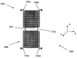
도 6은 본 발명의 일 실시예에 따른 도 2의 전극 재료(140)와 같은 전극 재료의 패턴(600)의 개략적인 예시도이다. 패턴(600)은 감지 또는 수신측(604) 및 작동 또는 론칭(launching) 측(608)을 갖고 있다. 감지 또는 수신측(604)은 디바이스(예컨대, 도 1A 및 도 1B의 디바이스(100))로부터의 출력 신호를 제공한다. 작동 또는 론칭 측(608)은 입력 신호를 디바이스에 제공하는데 사용된다. 감지 또는 수신측(604)은 예컨대, 도 2의 전극 재료(140)에 관하여 여기서 이전에 설명된 바와 유사하게 두 세트의 전극 재료 위치(140a, 140b)(전반적으로 140)를 갖고 있 다. 마찬가지로, 작동 또는 론칭 측(608)은 여기서 이전에 설명된 바와 유사하게 두 세트의 전극 재료 위치(140c, 140d)(전반적으로 140)를 갖고 있다.FIG. 6 is a schematic illustration of a
일 실시예에서의 동작시, 공진 디바이스의 멤브레인(104)에 진동을 발생하기 위해 반대 극성의 시변 전기 신호들이 작동 또는 론칭 측(608)의 전극 재료 위치(140c, 140d)에 인가된다. 멤브레인(104)의 외부 에지(612)가 또한 도 6에 도시되어 있다. 동작시, 전극 재료 위치(140c, 140d)는 전극 재료 위치(140a, 140b)와 함께, 예컨대, 공진 디바이스(예컨대, 멤브레인(104)의 표면 또는 멤브레인(104)의 위 또는 아래에 위치된 재료의 표면)와 접촉하는 유체의 영향을 측정하는데 사용된다. 몇몇 실시예들에서, 전극 재료 위치(140c, 140d)는 전극 재료 위치(140a, 140b)와 함께, 예컨대, 멤브레인(104)의 표면과 접촉하는 생물학적 물질의 영향을 측정하는데 사용된다.In operation in one embodiment, time-varying electrical signals of opposite polarities are applied to
도 7은 본 발명의 일 실시예에 따른 도 2의 전극 재료(140)와 같은 전극 재료의 패턴(700)의 개략적인 예시도이다. 패턴(700)은 감지 또는 수신측(704)과 작동 또는 론칭 측(708)을 갖고 있다. 감지 또는 수신측(704)은 두 세트의 전극 재료 위치(140a, 140b)를 갖고 있다. 마찬가지로, 작동 또는 론칭 측(708)은 두 세트의 전극 재료 위치(140c, 140d)를 갖고 있다. 본 발명에 따른 디바이스는 전극 재료와 전기 응답 재료의 조합이 하나 이상의 감지 또는 수신 소자를 생성하도록 제조될 수 있다. 유사하게, 본 발명에 따른 디바이스는 전극 재료와 전기 응답 재료의 조합이 하나 이상의 작동 또는 론칭 소자를 생성하도록 제조될 수 있다.FIG. 7 is a schematic illustration of a
일 실시예에서의 동작시, 공진 디바이스의 멤브레인(104)에 진동을 발생하 기 위해 반대 극성의 시변 전기 신호들이 전극 재료 위치(140c, 140d)에 인가된다. 멤브레인(104)의 외부 에지(712)가 또한 도 7에 도시되어 있다. 일 예로서, 동작시, 전극 재료 위치(140c, 140d)는 전극 재료 위치(140a, 140b)와 함께, 예컨대, 공진 디바이스와 접촉하는 유체의 영향을 측정하는데 사용된다.In operation in one embodiment, time-varying electrical signals of opposite polarities are applied to
이 실시예에서, 멤브레인(104)은 X-Z 평면에서 보았을 때 직사각형 형상을 갖고 있다. 본 발명의 원리를 포함하는 멤브레인(그리고 또한, 예컨대, 도 1의 현수 구조(142))의 대안적인 기하학적 구조도 가능하다. 또한, 이 실시예에서, 감지 또는 수신(704) 및 작동 또는 론칭측(708)은 함께, X-Z 평면에서 보았을 때 대체로 직사각형 형상을 갖고 있다. 본 발명의 원리를 포함하는 감지 또는 수신측(704, 708) 중 하나 또는 둘 다의 대안적인 기하학적 구조가 가능하다. 일 예로서, 멤브레인(104), 현수 구조(142) 및 전극(140)(예컨대, 감지 또는 수신측(704) 및 작동 또는 론칭측(708))은 X-Z 평면에서 보았을 때 다양한 형상을 가질 수 있다.In this embodiment, the
일 실시예에서, 멤브레인(104), 현수 구조(142), 감지 또는 수신측(704) 및 작동 또는 론칭측(708)은 모두 X-Z 평면에서 보았을 때 대체로 정방형 형상을 갖고 있다. 다른 실시예에서, 멤브레인(104) 및 현수 구조(142)는 X-Z 평면에서 보았을 때 대체로 원형 형상을 갖는다. 이 실시예에서, 전극 재료 위치(140a, 140b, 140c, 140d)는 모두 X-Z 평면에서 보았을 때 대체로 원형 형상을 갖는다. 이 실시예에서, 전극 재료 위치(140a, 140b, 140c, 140d)는 서로 대체로 동심 링을 형성하는 환형 형상(X-Z 평면에서 보았을 때)을 개별적으로 갖는다.In one embodiment, the
일 예시로서, 실험을 행하여 본 발명의 원리를 포함하는 공진 디바이스에 대해 데이터를 얻었다. 실험은 디바이스의 캐비티 및 감지 표면(예컨대, 도 1A의 디바이스(100)의 캐비티(124) 및 캐비티(124) 내의 표면)을, 예컨대, 미국 미주리주 세인트루이스에 사무소를 둔 시그마 알드리치(Sigma-Aldrich)사에서 판매하는 1x PBS(phosphate buffered saline) 유체에 노출시켜 행해졌다. 도 8은 도 1A의 디바이스(100)를 사용하여 얻어진 전달 함수 크기의 도면(800)을 나타낸다. 도면(800)의 Y 축(804)은 디바이스(100)의 출력 신호에 대한 디바이스(100)의 입력 신호의 크기이다. 도면(800)의 X 축(808)은 주파수(Hz)를 나타낸다.As an example, experiments were conducted to obtain data on resonant devices that incorporate the principles of the present invention. Experiments have shown the cavity and sensing surface of a device (eg, the
곡선(812)은 본 발명의 원리를 포함하지 않는 영역(120)(즉, 도 1B의 영역(120))을 가진 전기활성 재료 디바이스(100)의 전달 함수 크기 대 주파수이다. 곡선(816)은 본 발명의 원리를 포함하는 영역(120)(즉, 도 2의 영역(120))을 가진 전기활성 재료 디바이스(100)의 전달 함수 크기 대 주파수이다. 참고로, 곡선(812, 816)과 연관된 데이터를 얻기 위해 사용된 공진 디바이스(100)는 도 6의 패턴(600)에 대응하는 전극 재료 패턴을 갖고 있다.
곡선(812)은 전기 응답 디바이스의 각종 우세한 공진 모드에 대응하는 두 영역(820, 824)을 갖고 있다. 그러나, 곡선(816)은 공진 디바이스의 공진 모드들이 곡선(816) 상의 다른 위치에 비해 상대적으로 우세한 한 영역(828)을 갖고 있다. 이 실험에서, 곡선(816)의 영역(828)이 바람직한 통과 대역이며, 이는, 영역(828)의 좌측 및 우측으로 곡선(816)이 급감한다는 관찰에 의해 설명되는 바와 같이 영역(828)은 전기 응답 디바이스의 인접 공진 모드로부터 대체로 분리되어 있기 때문이다. 이 방식에서, 도 2의 디바이스(100)의 영역(120)의 영역들(244)을 생성하는 재료(132)의 적어도 일부의 선택적 제거는 디바이스(100)의 적어도 하나의 공진 모드를 실질적으로 수정한다. 약 16 MHz와 약 26 MHz 사이에서 일부 공진 모드와 연관된 모드 중첩 및 스필 오버(spillover)가 감소되어, 디바이스(100)의 적어도 하나의 공진 응답 모드가 곡선(816)의 영역(828)에 예시된 바와 같이 보강된다.
일 예시로서, 다른 실험을 행하여 본 발명의 원리를 포함하는 공진 디바이스에 대해 데이터를 얻었다. 실험은 디바이스의 캐비티 및 감지 표면(예컨대, 도 1A의 디바이스(100)의 캐비티(124) 및 캐비티(124)내의 표면)을, 예컨대, 미국 미주리주 세인트루이스에 사무소를 둔 시그마 알드리치(Sigma-Aldrich)사에서 판매하는 1x PBS(phosphate buffered saline) 유체에 노출시켜 행해졌다. 도 9는 도 1A의 디바이스(100)를 사용하여 얻어진 전달 함수 크기의 도면(900)을 예시한다. 도면(900)의 Y 축(904)은 디바이스(100)의 출력 신호에 대한 디바이스(100)의 입력 신호의 크기이다. 도면(900)의 X 축(908)은 주파수(Hz)이다.As one example, other experiments were conducted to obtain data for resonant devices that incorporate the principles of the present invention. Experiments have shown the cavity and sensing surface of a device (eg, the
곡선(912)은 본 발명의 원리를 포함하지 않는 영역(120)(즉, 도 1B의 영역(120))을 가진 전기활성 재료 디바이스(100)의 전달 함수 크기 대 주파수이다. 곡선(916)은 본 발명의 원리를 포함하는 영역(120)(즉, 도 2의 영역(120))을 가진 디바이스(100)의 전달 함수 크기 대 주파수이다. 참고로, 곡선(912, 916)과 연관된 데이터를 얻기 위해 사용된 공진 디바이스(100)는 도 7의 패턴(700)에 대응하는 전극 재료 패턴을 갖고 있다.
곡선(912)은 공진 디바이스의 각종 우세한 공진 모드에 대응하는 영 역(920)을 갖고 있다. 곡선(916)은 공진 디바이스의 공진 모드들 중 하나가 곡선(916) 상의 다른 위치에 비해 영역(928)에 예시된 적어도 하나의 공진 모드를 보강하기 위해 수정된 영역(928)을 갖고 있다. 이 실험에서, 곡선(916)의 영역(928)이 바람직한 통과 대역이며, 이는, 영역(928)의 좌측 및 우측으로 곡선(916)이 급감하고 영역(928)의 좌우측으로 도시된 실질적인 공진 모드가 없다는 관찰에 의해 설명되는 바와 같이 영역(828)은 전기 응답 디바이스의 인접 공진 모드로부터 대체로 분리되어 있기 때문이다. 대조적으로, 예컨대, 곡선(912)의 영역(920)은 영역(920)에 인접한 적어도 하나의 실질적인 공진 모드(940)를 갖고 있다. 이 방식에서, 곡선(912)에 대응하는 디바이스는 적어도 하나의 공진 모드(940)의 존재 때문에 덜 바람직한 통과 대역 영역(920)을 갖는다. 상기 디바이스는 본 발명의 원리를 포함하지 않고 달성되는 경우보다 바람직한 통과 대역, 주파수에 대한 좁은 대역폭 및 낮은 전송 손실을 가지며, 이는 영역(920, 940)에서의 피크와 비교되는 영역(928)에서의 보다 뚜렷한 피크에 의해 증명된다. 바람직한 통과 대역, 좁은 대역폭 및 낮은 전송 손실이 또한 유체 로딩의 부재시도 상기 디바이스에서 달성된다.
또한, 곡선(916)의 영역(928)은 영역(928)에서의 적어도 하나의 공진 모드가 곡선(912)의 상응하는 영역(920)에 비해 실질적으로 수정되었음을 나타낸다. 실질적인 수정은 도 2의 디바이스(100)의 영역(120)의 영역들(244)을 생성하는 전기활성 재료(132)의 적어도 일부의 제거로 인한 것이다. 약 16 MHz와 약 26 MHz 사이의 일부 공진 모드들과 연관된 모드 중첩 및 스필 오버가 곡선(916)의 영 역(928) 내에서 감소됨으로써, 곡선(916)의 영역(928)에서 디바이스(100)의 적어도 하나의 공진 응답 모드가 보강된다.Furthermore,
여기서 설명된 것의 변경, 수정 및 다른 구현이 본 발명의 취지 및 범위로부터 벗어나지 않고 당업자에 의해 일어날 수 있다. 따라서, 본 발명은 이전에 예시한 설명에 의해서만 정의되어서는 안 된다Changes, modifications, and other implementations of those described herein can occur by those skilled in the art without departing from the spirit and scope of the invention. Accordingly, the present invention should not be defined solely by the description exemplified previously.
본 발명에서 구조적 특성(예컨대, 강성 및 질량 특성)의 선택적 변화로 바람직한 공진 모드 형상이 얻어진다. 예컨대, 여기 수단을 구조 변화와 상관시킴으로써 바람직한 공진이 선택적으로 여기되어, 바람직한 통과 대역이 얻어진다. 감지 수단을 구조 변화와 상관시킴으로써 바람직한 공진의 선택적 감지가 가능하고, 또한 바람직한 통과 대역이 얻어진다.Selective changes in structural properties (e.g., stiffness and mass properties) in the present invention yield desirable resonance mode shapes. For example, by correlating the excitation means with the structural change, the desired resonance is selectively excited to obtain the desired pass band. By correlating the sensing means with the structural change, selective sensing of the desired resonance is possible, and the desired passband is obtained.
일 실시예에서, 여기 및 감지 수단을 디바이스의 구조적 특성 변화와 상관시킴으로써 전기 필터(예컨대, SAW 디바이스 또는 FBAR 디바이스)는 구조적 수정없이 달성되는 경우보다 바람직한 통과 대역, 좁은 대역폭 및 낮은 전송 손실을 갖게 된다.In one embodiment, by correlating the excitation and sensing means with changes in the structural characteristics of the device, the electrical filter (eg, SAW device or FBAR device) has a desirable passband, narrow bandwidth and lower transmission loss than would be achieved without structural modification. .
Claims (58)
Applications Claiming Priority (3)
| Application Number | Priority Date | Filing Date | Title |
|---|---|---|---|
| US66893305P | 2005-04-06 | 2005-04-06 | |
| US60/668,933 | 2005-04-06 | ||
| PCT/US2006/012491 WO2006107961A2 (en) | 2005-04-06 | 2006-04-05 | Electrically responsive device |
Publications (2)
| Publication Number | Publication Date |
|---|---|
| KR20080007552A KR20080007552A (en) | 2008-01-22 |
| KR101245296B1 true KR101245296B1 (en) | 2013-03-19 |
Family
ID=36717063
Family Applications (1)
| Application Number | Title | Priority Date | Filing Date |
|---|---|---|---|
| KR1020077022508A KR101245296B1 (en) | 2005-04-06 | 2006-04-05 | Electrically responsive device |
Country Status (5)
| Country | Link |
|---|---|
| US (1) | US8536037B2 (en) |
| EP (1) | EP1872474A2 (en) |
| JP (1) | JP5078873B2 (en) |
| KR (1) | KR101245296B1 (en) |
| WO (1) | WO2006107961A2 (en) |
Cited By (1)
| Publication number | Priority date | Publication date | Assignee | Title |
|---|---|---|---|---|
| US11626648B2 (en) | 2018-08-21 | 2023-04-11 | Lg Energy Solution, Ltd. | Battery module including bus bar plate |
Families Citing this family (25)
| Publication number | Priority date | Publication date | Assignee | Title |
|---|---|---|---|---|
| DE10224567B4 (en) * | 2002-06-03 | 2014-10-23 | Boehringer Ingelheim Vetmedica Gmbh | Sensor arrangement and method for operating a sensor arrangement |
| US7497133B2 (en) | 2004-05-24 | 2009-03-03 | Drexel University | All electric piezoelectric finger sensor (PEFS) for soft material stiffness measurement |
| CA2637930C (en) * | 2006-01-23 | 2016-09-06 | Drexel University | Self-exciting, self-sensing piezoelectric cantilever sensor |
| US8171795B1 (en) | 2006-01-23 | 2012-05-08 | Drexel University | Self-exciting, self-sensing piezoelectric cantilever sensor for detection of airborne analytes directly in air |
| US8286486B2 (en) * | 2006-05-10 | 2012-10-16 | Drexel University | Molecular control of surface coverage |
| US8481335B2 (en) * | 2006-11-27 | 2013-07-09 | Drexel University | Specificity and sensitivity enhancement in cantilever sensing |
| WO2008067386A2 (en) | 2006-11-28 | 2008-06-05 | Drexel University | Piezoelectric microcantilever sensors for biosensing |
| US7992431B2 (en) | 2006-11-28 | 2011-08-09 | Drexel University | Piezoelectric microcantilevers and uses in atomic force microscopy |
| WO2008109205A2 (en) | 2007-02-01 | 2008-09-12 | Drexel University | A hand-held phase-shift detector for sensor applications |
| WO2008101199A1 (en) | 2007-02-16 | 2008-08-21 | Drexel University | Enhanced sensitivity of a cantilever sensor via specific bindings |
| US8512947B2 (en) | 2007-02-16 | 2013-08-20 | Drexel University | Detection of nucleic acids using a cantilever sensor |
| FR2916271B1 (en) * | 2007-05-14 | 2009-08-28 | St Microelectronics Sa | ELECTRONIC CIRCUIT FOR MEASURING MASS OF BIOLOGICAL MATERIAL AND METHOD OF MANUFACTURE |
| WO2009035732A2 (en) * | 2007-05-30 | 2009-03-19 | Drexel University | Detection and quantification of biomarkers via a piezoelectric cantilever sensor |
| US20090120168A1 (en) * | 2007-11-08 | 2009-05-14 | Schlumberger Technology Corporation | Microfluidic downhole density and viscosity sensor |
| US8241569B2 (en) * | 2007-11-23 | 2012-08-14 | Drexel University | Lead-free piezoelectric ceramic films and a method for making thereof |
| US8236508B2 (en) * | 2008-01-29 | 2012-08-07 | Drexel University | Detecting and measuring live pathogens utilizing a mass detection device |
| WO2009126378A2 (en) | 2008-03-11 | 2009-10-15 | Drexel University | Enhanced detection sensitivity with piezoelectric microcantilever sensors |
| CN102066928B (en) * | 2008-05-16 | 2015-08-05 | 德瑞索大学 | The system and method for assessment tissue |
| IT1392736B1 (en) | 2008-12-09 | 2012-03-16 | St Microelectronics Rousset | INTEGRATED TORSIONAL MICRO-BALANCE DEVICE IN MEMS TECHNOLOGY AND ITS MANUFACTURING PROCESS |
| US8722427B2 (en) * | 2009-10-08 | 2014-05-13 | Drexel University | Determination of dissociation constants using piezoelectric microcantilevers |
| US20110086368A1 (en) * | 2009-10-08 | 2011-04-14 | Drexel University | Method for immune response detection |
| CN104596906B (en) * | 2015-01-16 | 2017-08-25 | 上海大学 | The water oxygen air penetrability measuring system of many measurement heads |
| CN104614403B (en) * | 2015-01-22 | 2017-05-24 | 江西师范大学 | Sensor, forming method of sensor, and method for defecting gas |
| JP6945357B2 (en) * | 2017-06-08 | 2021-10-06 | 東京エレクトロン株式会社 | Control device. |
| CN109450401B (en) * | 2018-09-20 | 2022-03-18 | 天津大学 | Flexible single crystal lamb wave resonator and method of forming the same |
Citations (2)
| Publication number | Priority date | Publication date | Assignee | Title |
|---|---|---|---|---|
| US4278492A (en) | 1980-01-21 | 1981-07-14 | Hewlett-Packard Company | Frequency trimming of surface acoustic wave devices |
| US20030020367A1 (en) | 2001-01-10 | 2003-01-30 | Yoshio Maeda | Surface acoustic wave device and its manufacturing method |
Family Cites Families (23)
| Publication number | Priority date | Publication date | Assignee | Title |
|---|---|---|---|---|
| US4364016A (en) * | 1980-11-03 | 1982-12-14 | Sperry Corporation | Method for post fabrication frequency trimming of surface acoustic wave devices |
| WO1989008336A1 (en) * | 1988-02-29 | 1989-09-08 | The Regents Of The University Of California | Plate-mode ultrasonic sensor |
| US5189914A (en) * | 1988-02-29 | 1993-03-02 | The Regents Of The University Of California | Plate-mode ultrasonic sensor |
| US5490034A (en) * | 1989-01-13 | 1996-02-06 | Kopin Corporation | SOI actuators and microsensors |
| JPH0325343A (en) * | 1989-06-23 | 1991-02-04 | Nec Corp | Sensor device |
| US4952832A (en) * | 1989-10-24 | 1990-08-28 | Sumitomo Electric Industries, Ltd. | Surface acoustic wave device |
| JPH0497611A (en) * | 1990-08-15 | 1992-03-30 | Clarion Co Ltd | Manufacture of surface acoustic wave element |
| JPH04199906A (en) * | 1990-11-29 | 1992-07-21 | Kokusai Electric Co Ltd | Surface acoustic wave resonator |
| US5668303A (en) * | 1992-04-30 | 1997-09-16 | Forschung E.V Fraunhofer-Gesellschaft Zur Foerderung Der Angewandten | Sensor having a membrane as part of an electromechanical resonance circuit forming receiver and transmitter converter with interdigital structures spaced apart from one another |
| US5836203A (en) * | 1996-10-21 | 1998-11-17 | Sandia Corporation | Magnetically excited flexural plate wave apparatus |
| US6091182A (en) * | 1996-11-07 | 2000-07-18 | Ngk Insulators, Ltd. | Piezoelectric/electrostrictive element |
| JP3470031B2 (en) * | 1997-12-22 | 2003-11-25 | 京セラ株式会社 | Manufacturing method of surface acoustic wave device |
| US6323580B1 (en) * | 1999-04-28 | 2001-11-27 | The Charles Stark Draper Laboratory, Inc. | Ferroic transducer |
| CA2404137C (en) * | 2000-03-20 | 2006-07-11 | The Charles Stark Draper Laboratory, Inc. | Flexural plate wave sensor and array |
| US6455980B1 (en) * | 2000-08-28 | 2002-09-24 | The Charles Stark Draper Laboratory, Inc. | Resonator with preferred oscillation mode |
| US6506620B1 (en) * | 2000-11-27 | 2003-01-14 | Microscan Systems Incorporated | Process for manufacturing micromechanical and microoptomechanical structures with backside metalization |
| US6946314B2 (en) * | 2001-01-02 | 2005-09-20 | The Charles Stark Draper Laboratory, Inc. | Method for microfabricating structures using silicon-on-insulator material |
| WO2002054475A1 (en) * | 2001-01-02 | 2002-07-11 | The Charles Stark Draper Laboratory, Inc. | Method for microfabricating structures using silicon-on-insulator material |
| US6511915B2 (en) * | 2001-03-26 | 2003-01-28 | Boston Microsystems, Inc. | Electrochemical etching process |
| US7207222B2 (en) * | 2001-08-28 | 2007-04-24 | Sensorchem International Corporation | Electromagnetic piezoelectric acoustic sensor |
| JP4281327B2 (en) * | 2002-10-28 | 2009-06-17 | 株式会社村田製作所 | Manufacturing method of surface wave device |
| JP4345328B2 (en) * | 2003-03-13 | 2009-10-14 | セイコーエプソン株式会社 | Surface acoustic wave device and manufacturing method thereof |
| US7045407B2 (en) * | 2003-12-30 | 2006-05-16 | Intel Corporation | Amorphous etch stop for the anisotropic etching of substrates |
-
2006
- 2006-04-05 JP JP2008505449A patent/JP5078873B2/en not_active Expired - Fee Related
- 2006-04-05 WO PCT/US2006/012491 patent/WO2006107961A2/en active Application Filing
- 2006-04-05 KR KR1020077022508A patent/KR101245296B1/en not_active IP Right Cessation
- 2006-04-05 EP EP06749241A patent/EP1872474A2/en not_active Withdrawn
- 2006-04-05 US US11/398,308 patent/US8536037B2/en not_active Expired - Fee Related
Patent Citations (2)
| Publication number | Priority date | Publication date | Assignee | Title |
|---|---|---|---|---|
| US4278492A (en) | 1980-01-21 | 1981-07-14 | Hewlett-Packard Company | Frequency trimming of surface acoustic wave devices |
| US20030020367A1 (en) | 2001-01-10 | 2003-01-30 | Yoshio Maeda | Surface acoustic wave device and its manufacturing method |
Cited By (1)
| Publication number | Priority date | Publication date | Assignee | Title |
|---|---|---|---|---|
| US11626648B2 (en) | 2018-08-21 | 2023-04-11 | Lg Energy Solution, Ltd. | Battery module including bus bar plate |
Also Published As
| Publication number | Publication date |
|---|---|
| US8536037B2 (en) | 2013-09-17 |
| US20060228657A1 (en) | 2006-10-12 |
| JP5078873B2 (en) | 2012-11-21 |
| WO2006107961A2 (en) | 2006-10-12 |
| EP1872474A2 (en) | 2008-01-02 |
| WO2006107961A3 (en) | 2007-04-12 |
| KR20080007552A (en) | 2008-01-22 |
| JP2008536395A (en) | 2008-09-04 |
Similar Documents
| Publication | Publication Date | Title |
|---|---|---|
| KR101245296B1 (en) | Electrically responsive device | |
| EP3377886B1 (en) | Acoustic resonator with reduced mechanical clamping of an active region for enhanced shear mode response | |
| US6851297B2 (en) | Flexural plate wave sensor and array | |
| US5668303A (en) | Sensor having a membrane as part of an electromechanical resonance circuit forming receiver and transmitter converter with interdigital structures spaced apart from one another | |
| JP5225981B2 (en) | Self-excited and self-detecting piezoelectric cantilever sensor for direct detection of airborne analytes in air | |
| US8349611B2 (en) | Resonant sensors and methods of use thereof for the determination of analytes | |
| US10352904B2 (en) | Acoustic resonator devices and methods providing patterned functionalization areas | |
| WO2000026636A1 (en) | Qcm sensor | |
| WO2007006843A1 (en) | Micromechanical sensor, sensor array and method | |
| WO2010052841A1 (en) | Detection sensor and detection sensor transducer | |
| WO2011019702A1 (en) | Mems in-plane resonators | |
| US9164051B2 (en) | Electrically responsive device | |
| US20140182361A1 (en) | Piezoresistive nems array network | |
| JP2009236607A (en) | Qcm device | |
| US11549913B2 (en) | Shear-mode chemical/physical sensor for liquid environment sensing and method for producing the same | |
| Alava et al. | Silicon-based micromembranes with piezoelectric actuation and piezoresistive detection for sensing purposes in liquid media | |
| JP2004093574A (en) | Cantilever with force azimuth sensor for atomic force microscope | |
| JP4803802B2 (en) | Mass measuring device | |
| Jupe et al. | Development of a piezoelectric flexural plate-wave (FPW) biomems-sensor for rapid point-of-care diagnostics | |
| JP2006038584A (en) | Chemical sensor and measuring instrument | |
| Mahdavi | Resonant MEMS Piezoelectric Balances and Strain-Gauges | |
| Park | Capacitive micromachined ultrasonic transducer (cmut) for chemical detection in air | |
| US9638616B2 (en) | Devices and methods for gravimetric sensing in liquid environments | |
| Guirardel et al. | On-chip self-sensing function of 4/spl times/4 matrix micromachined resonating piezoelectric membranes for mass detection applications [biosensor/chemical sensor applications] |
Legal Events
| Date | Code | Title | Description |
|---|---|---|---|
| A201 | Request for examination | ||
| E902 | Notification of reason for refusal | ||
| E701 | Decision to grant or registration of patent right | ||
| GRNT | Written decision to grant | ||
| FPAY | Annual fee payment |
Payment date: 20160912 Year of fee payment: 4 |
|
| FPAY | Annual fee payment |
Payment date: 20170912 Year of fee payment: 5 |
|
| FPAY | Annual fee payment |
Payment date: 20180910 Year of fee payment: 6 |
|
| LAPS | Lapse due to unpaid annual fee |