KR101240150B1 - Closure device, deployment apparatus, and method of deploying a closure device - Google Patents
Closure device, deployment apparatus, and method of deploying a closure device Download PDFInfo
- Publication number
- KR101240150B1 KR101240150B1 KR1020107007950A KR20107007950A KR101240150B1 KR 101240150 B1 KR101240150 B1 KR 101240150B1 KR 1020107007950 A KR1020107007950 A KR 1020107007950A KR 20107007950 A KR20107007950 A KR 20107007950A KR 101240150 B1 KR101240150 B1 KR 101240150B1
- Authority
- KR
- South Korea
- Prior art keywords
- delete delete
- distal
- plug
- wire
- closure device
- Prior art date
Links
- 238000000034 method Methods 0.000 title abstract description 34
- 229910052751 metal Inorganic materials 0.000 claims description 20
- 239000002184 metal Substances 0.000 claims description 20
- 229910000861 Mg alloy Inorganic materials 0.000 claims description 14
- 239000011777 magnesium Substances 0.000 claims description 9
- FYYHWMGAXLPEAU-UHFFFAOYSA-N Magnesium Chemical compound [Mg] FYYHWMGAXLPEAU-UHFFFAOYSA-N 0.000 claims description 6
- 229910052749 magnesium Inorganic materials 0.000 claims description 6
- 239000004033 plastic Substances 0.000 claims description 4
- 229920003023 plastic Polymers 0.000 claims description 4
- 238000006065 biodegradation reaction Methods 0.000 claims description 2
- 230000007246 mechanism Effects 0.000 abstract description 41
- 210000004204 blood vessel Anatomy 0.000 abstract description 30
- 238000007789 sealing Methods 0.000 abstract description 14
- 230000000740 bleeding effect Effects 0.000 abstract description 11
- 210000000056 organ Anatomy 0.000 abstract description 4
- 238000001574 biopsy Methods 0.000 abstract 1
- 239000012530 fluid Substances 0.000 abstract 1
- 239000000126 substance Substances 0.000 abstract 1
- 210000001519 tissue Anatomy 0.000 description 47
- 210000001367 artery Anatomy 0.000 description 14
- 239000008280 blood Substances 0.000 description 11
- 210000004369 blood Anatomy 0.000 description 11
- 230000002792 vascular Effects 0.000 description 11
- 208000032843 Hemorrhage Diseases 0.000 description 10
- 238000001356 surgical procedure Methods 0.000 description 10
- 230000008901 benefit Effects 0.000 description 9
- 230000006835 compression Effects 0.000 description 8
- 238000007906 compression Methods 0.000 description 8
- 229920000642 polymer Polymers 0.000 description 8
- 238000011282 treatment Methods 0.000 description 8
- 238000003466 welding Methods 0.000 description 8
- 230000017531 blood circulation Effects 0.000 description 7
- 238000005452 bending Methods 0.000 description 5
- 230000006870 function Effects 0.000 description 5
- 239000007943 implant Substances 0.000 description 5
- 238000004519 manufacturing process Methods 0.000 description 5
- 230000002093 peripheral effect Effects 0.000 description 5
- 239000013060 biological fluid Substances 0.000 description 4
- 238000013016 damping Methods 0.000 description 4
- 210000001105 femoral artery Anatomy 0.000 description 4
- 238000003780 insertion Methods 0.000 description 4
- 230000037431 insertion Effects 0.000 description 4
- 230000008569 process Effects 0.000 description 4
- 206010018852 Haematoma Diseases 0.000 description 3
- 230000009471 action Effects 0.000 description 3
- 238000005266 casting Methods 0.000 description 3
- 238000005056 compaction Methods 0.000 description 3
- 230000007797 corrosion Effects 0.000 description 3
- 238000005260 corrosion Methods 0.000 description 3
- 238000011161 development Methods 0.000 description 3
- 238000005242 forging Methods 0.000 description 3
- 238000010438 heat treatment Methods 0.000 description 3
- 230000023597 hemostasis Effects 0.000 description 3
- 238000010030 laminating Methods 0.000 description 3
- 238000003698 laser cutting Methods 0.000 description 3
- 238000003754 machining Methods 0.000 description 3
- 230000014759 maintenance of location Effects 0.000 description 3
- 239000003550 marker Substances 0.000 description 3
- 239000000463 material Substances 0.000 description 3
- 150000002739 metals Chemical class 0.000 description 3
- 238000000465 moulding Methods 0.000 description 3
- 206010033675 panniculitis Diseases 0.000 description 3
- 238000012545 processing Methods 0.000 description 3
- 229910052761 rare earth metal Inorganic materials 0.000 description 3
- 150000002910 rare earth metals Chemical class 0.000 description 3
- 210000004304 subcutaneous tissue Anatomy 0.000 description 3
- 230000001225 therapeutic effect Effects 0.000 description 3
- 229920001169 thermoplastic Polymers 0.000 description 3
- 239000004416 thermosoftening plastic Substances 0.000 description 3
- 206010003226 Arteriovenous fistula Diseases 0.000 description 2
- 230000015572 biosynthetic process Effects 0.000 description 2
- 230000000747 cardiac effect Effects 0.000 description 2
- 238000007887 coronary angioplasty Methods 0.000 description 2
- 230000008878 coupling Effects 0.000 description 2
- 238000010168 coupling process Methods 0.000 description 2
- 238000005859 coupling reaction Methods 0.000 description 2
- 238000002788 crimping Methods 0.000 description 2
- 238000001125 extrusion Methods 0.000 description 2
- 238000001727 in vivo Methods 0.000 description 2
- 230000002427 irreversible effect Effects 0.000 description 2
- 239000002906 medical waste Substances 0.000 description 2
- 238000012986 modification Methods 0.000 description 2
- 230000004048 modification Effects 0.000 description 2
- 210000005036 nerve Anatomy 0.000 description 2
- 229920001432 poly(L-lactide) Polymers 0.000 description 2
- 239000004633 polyglycolic acid Substances 0.000 description 2
- 229950008885 polyglycolic acid Drugs 0.000 description 2
- 238000012549 training Methods 0.000 description 2
- 229910052684 Cerium Inorganic materials 0.000 description 1
- 206010053567 Coagulopathies Diseases 0.000 description 1
- 229910052692 Dysprosium Inorganic materials 0.000 description 1
- 238000012276 Endovascular treatment Methods 0.000 description 1
- 229910052691 Erbium Inorganic materials 0.000 description 1
- 229910052693 Europium Inorganic materials 0.000 description 1
- 208000009087 False Aneurysm Diseases 0.000 description 1
- 229910052689 Holmium Inorganic materials 0.000 description 1
- JVTAAEKCZFNVCJ-REOHCLBHSA-N L-lactic acid Chemical compound C[C@H](O)C(O)=O JVTAAEKCZFNVCJ-REOHCLBHSA-N 0.000 description 1
- 229910052765 Lutetium Inorganic materials 0.000 description 1
- 229910052779 Neodymium Inorganic materials 0.000 description 1
- 206010033799 Paralysis Diseases 0.000 description 1
- 229910052777 Praseodymium Inorganic materials 0.000 description 1
- 229910052773 Promethium Inorganic materials 0.000 description 1
- 206010058360 Retroperitoneal haematoma Diseases 0.000 description 1
- 229910052772 Samarium Inorganic materials 0.000 description 1
- 229910052771 Terbium Inorganic materials 0.000 description 1
- 229910052775 Thulium Inorganic materials 0.000 description 1
- 206010048975 Vascular pseudoaneurysm Diseases 0.000 description 1
- 229910052769 Ytterbium Inorganic materials 0.000 description 1
- 230000001154 acute effect Effects 0.000 description 1
- 239000000853 adhesive Substances 0.000 description 1
- 238000004026 adhesive bonding Methods 0.000 description 1
- 230000001070 adhesive effect Effects 0.000 description 1
- 229910045601 alloy Inorganic materials 0.000 description 1
- 239000000956 alloy Substances 0.000 description 1
- 238000013459 approach Methods 0.000 description 1
- 230000000712 assembly Effects 0.000 description 1
- 238000000429 assembly Methods 0.000 description 1
- 230000036772 blood pressure Effects 0.000 description 1
- 239000000919 ceramic Substances 0.000 description 1
- GWXLDORMOJMVQZ-UHFFFAOYSA-N cerium Chemical compound [Ce] GWXLDORMOJMVQZ-UHFFFAOYSA-N 0.000 description 1
- 230000035602 clotting Effects 0.000 description 1
- 238000000576 coating method Methods 0.000 description 1
- 238000012937 correction Methods 0.000 description 1
- 238000005520 cutting process Methods 0.000 description 1
- 230000006378 damage Effects 0.000 description 1
- 230000006735 deficit Effects 0.000 description 1
- 238000006073 displacement reaction Methods 0.000 description 1
- KBQHZAAAGSGFKK-UHFFFAOYSA-N dysprosium atom Chemical compound [Dy] KBQHZAAAGSGFKK-UHFFFAOYSA-N 0.000 description 1
- 238000010894 electron beam technology Methods 0.000 description 1
- UYAHIZSMUZPPFV-UHFFFAOYSA-N erbium Chemical compound [Er] UYAHIZSMUZPPFV-UHFFFAOYSA-N 0.000 description 1
- OGPBJKLSAFTDLK-UHFFFAOYSA-N europium atom Chemical compound [Eu] OGPBJKLSAFTDLK-UHFFFAOYSA-N 0.000 description 1
- 238000000605 extraction Methods 0.000 description 1
- KJZYNXUDTRRSPN-UHFFFAOYSA-N holmium atom Chemical compound [Ho] KJZYNXUDTRRSPN-UHFFFAOYSA-N 0.000 description 1
- 230000001939 inductive effect Effects 0.000 description 1
- 229910052746 lanthanum Inorganic materials 0.000 description 1
- FZLIPJUXYLNCLC-UHFFFAOYSA-N lanthanum atom Chemical compound [La] FZLIPJUXYLNCLC-UHFFFAOYSA-N 0.000 description 1
- OHSVLFRHMCKCQY-UHFFFAOYSA-N lutetium atom Chemical compound [Lu] OHSVLFRHMCKCQY-UHFFFAOYSA-N 0.000 description 1
- 238000002844 melting Methods 0.000 description 1
- 230000008018 melting Effects 0.000 description 1
- 210000004115 mitral valve Anatomy 0.000 description 1
- 239000012768 molten material Substances 0.000 description 1
- 210000003205 muscle Anatomy 0.000 description 1
- QEFYFXOXNSNQGX-UHFFFAOYSA-N neodymium atom Chemical compound [Nd] QEFYFXOXNSNQGX-UHFFFAOYSA-N 0.000 description 1
- PUDIUYLPXJFUGB-UHFFFAOYSA-N praseodymium atom Chemical compound [Pr] PUDIUYLPXJFUGB-UHFFFAOYSA-N 0.000 description 1
- 238000003825 pressing Methods 0.000 description 1
- VQMWBBYLQSCNPO-UHFFFAOYSA-N promethium atom Chemical compound [Pm] VQMWBBYLQSCNPO-UHFFFAOYSA-N 0.000 description 1
- KZUNJOHGWZRPMI-UHFFFAOYSA-N samarium atom Chemical compound [Sm] KZUNJOHGWZRPMI-UHFFFAOYSA-N 0.000 description 1
- 229910052706 scandium Inorganic materials 0.000 description 1
- SIXSYDAISGFNSX-UHFFFAOYSA-N scandium atom Chemical compound [Sc] SIXSYDAISGFNSX-UHFFFAOYSA-N 0.000 description 1
- 230000001953 sensory effect Effects 0.000 description 1
- 239000007787 solid Substances 0.000 description 1
- 230000003068 static effect Effects 0.000 description 1
- 238000011477 surgical intervention Methods 0.000 description 1
- GZCRRIHWUXGPOV-UHFFFAOYSA-N terbium atom Chemical compound [Tb] GZCRRIHWUXGPOV-UHFFFAOYSA-N 0.000 description 1
- 238000002560 therapeutic procedure Methods 0.000 description 1
- 230000000007 visual effect Effects 0.000 description 1
- 230000003245 working effect Effects 0.000 description 1
- NAWDYIZEMPQZHO-UHFFFAOYSA-N ytterbium Chemical compound [Yb] NAWDYIZEMPQZHO-UHFFFAOYSA-N 0.000 description 1
Images


Classifications
-
- A—HUMAN NECESSITIES
- A61—MEDICAL OR VETERINARY SCIENCE; HYGIENE
- A61B—DIAGNOSIS; SURGERY; IDENTIFICATION
- A61B17/00—Surgical instruments, devices or methods, e.g. tourniquets
- A61B17/0057—Implements for plugging an opening in the wall of a hollow or tubular organ, e.g. for sealing a vessel puncture or closing a cardiac septal defect
-
- A—HUMAN NECESSITIES
- A61—MEDICAL OR VETERINARY SCIENCE; HYGIENE
- A61B—DIAGNOSIS; SURGERY; IDENTIFICATION
- A61B17/00—Surgical instruments, devices or methods, e.g. tourniquets
- A61B2017/00004—(bio)absorbable, (bio)resorbable, resorptive
-
- A—HUMAN NECESSITIES
- A61—MEDICAL OR VETERINARY SCIENCE; HYGIENE
- A61B—DIAGNOSIS; SURGERY; IDENTIFICATION
- A61B17/00—Surgical instruments, devices or methods, e.g. tourniquets
- A61B2017/00367—Details of actuation of instruments, e.g. relations between pushing buttons, or the like, and activation of the tool, working tip, or the like
-
- A—HUMAN NECESSITIES
- A61—MEDICAL OR VETERINARY SCIENCE; HYGIENE
- A61B—DIAGNOSIS; SURGERY; IDENTIFICATION
- A61B17/00—Surgical instruments, devices or methods, e.g. tourniquets
- A61B17/0057—Implements for plugging an opening in the wall of a hollow or tubular organ, e.g. for sealing a vessel puncture or closing a cardiac septal defect
- A61B2017/00575—Implements for plugging an opening in the wall of a hollow or tubular organ, e.g. for sealing a vessel puncture or closing a cardiac septal defect for closure at remote site, e.g. closing atrial septum defects
- A61B2017/00623—Introducing or retrieving devices therefor
-
- A—HUMAN NECESSITIES
- A61—MEDICAL OR VETERINARY SCIENCE; HYGIENE
- A61B—DIAGNOSIS; SURGERY; IDENTIFICATION
- A61B17/00—Surgical instruments, devices or methods, e.g. tourniquets
- A61B17/0057—Implements for plugging an opening in the wall of a hollow or tubular organ, e.g. for sealing a vessel puncture or closing a cardiac septal defect
- A61B2017/00637—Implements for plugging an opening in the wall of a hollow or tubular organ, e.g. for sealing a vessel puncture or closing a cardiac septal defect for sealing trocar wounds through abdominal wall
-
- A—HUMAN NECESSITIES
- A61—MEDICAL OR VETERINARY SCIENCE; HYGIENE
- A61B—DIAGNOSIS; SURGERY; IDENTIFICATION
- A61B17/00—Surgical instruments, devices or methods, e.g. tourniquets
- A61B17/0057—Implements for plugging an opening in the wall of a hollow or tubular organ, e.g. for sealing a vessel puncture or closing a cardiac septal defect
- A61B2017/00641—Implements for plugging an opening in the wall of a hollow or tubular organ, e.g. for sealing a vessel puncture or closing a cardiac septal defect for closing fistulae, e.g. anorectal fistulae
-
- A—HUMAN NECESSITIES
- A61—MEDICAL OR VETERINARY SCIENCE; HYGIENE
- A61B—DIAGNOSIS; SURGERY; IDENTIFICATION
- A61B17/00—Surgical instruments, devices or methods, e.g. tourniquets
- A61B17/0057—Implements for plugging an opening in the wall of a hollow or tubular organ, e.g. for sealing a vessel puncture or closing a cardiac septal defect
- A61B2017/00646—Type of implements
- A61B2017/00654—Type of implements entirely comprised between the two sides of the opening
-
- A—HUMAN NECESSITIES
- A61—MEDICAL OR VETERINARY SCIENCE; HYGIENE
- A61B—DIAGNOSIS; SURGERY; IDENTIFICATION
- A61B17/00—Surgical instruments, devices or methods, e.g. tourniquets
- A61B17/0057—Implements for plugging an opening in the wall of a hollow or tubular organ, e.g. for sealing a vessel puncture or closing a cardiac septal defect
- A61B2017/00646—Type of implements
- A61B2017/00659—Type of implements located only on one side of the opening
-
- A—HUMAN NECESSITIES
- A61—MEDICAL OR VETERINARY SCIENCE; HYGIENE
- A61B—DIAGNOSIS; SURGERY; IDENTIFICATION
- A61B17/00—Surgical instruments, devices or methods, e.g. tourniquets
- A61B17/0057—Implements for plugging an opening in the wall of a hollow or tubular organ, e.g. for sealing a vessel puncture or closing a cardiac septal defect
- A61B2017/00672—Locating means therefor, e.g. bleed back lumen
Abstract
본 발명은 조직을 통해 형성된 통로를 봉합하고 밀폐하기 위한 의료장치와 방법에 관한 것이다. 보다 구체적으로, 본 발명은 원위 또는 외측 가장자리 또는 표면, 및 근위 또는 내측 가장자리 또는 표면(즉 벽 두께)을 포함하는, 조직을 통해 형성된 통로를 봉합하고 밀폐하기 위한 장치, 및 출혈(또는 조직 또는 생체학적 유체의 흐름)을 조절하기 위해(또는 방지 또는 중지시키기 위해) 이러한 장치들을 전달하기 위한 기구 및 방법에 관한 것이다. 이 개구부들은 경피 형성 천자, 절개부, 또는 혈관, 장기, 및 이와 유사한 것과 같은, 생체 조직을 통해 형성된 그 외의 개구부들을 포함한다.The present invention relates to medical devices and methods for sealing and sealing passages formed through tissue. More specifically, the present invention provides a device for sealing and sealing a passage formed through tissue, including a distal or outer edge or surface, and a proximal or inner edge or surface (ie, wall thickness), and bleeding (or tissue or biopsy). Mechanisms and methods for delivering such devices to regulate (or prevent or stop) the flow of a chemical fluid). These openings include percutaneous punctures, incisions, or other openings formed through living tissue, such as blood vessels, organs, and the like.
Description
본 출원은, 2007년 9월 12일 출원된 미국 부분 특허출원 제 60/971618 호를 우선권으로 주장하며, 상기 문헌의 전체 내용을 참고한다. This application claims priority to US Partial Patent Application No. 60/971618, filed Sep. 12, 2007, which is incorporated by reference in its entirety.
본 발명은, 일반적으로 조직을 통과하는 통로를 봉합하고 밀폐하기 위한 의료장치 및 방법에 관한 것이다. 구체적으로, 본 발명은, 출혈 (또는, 다른 생물학적 유체 또는 조직의 유동)을 제어(또는 방지 또는 정지)하기 위하여 원위 또는 외측의 마진 또는 표면, 근위 또는 내측의 마진 또는 표면 (즉, 벽두께)를 포함하는 생물학적 조직을 통과하는 개구부를 봉합하거나 밀폐하기 위한 장치들 및, 상기 장치들을 전달하기 위한 장치 및 방법들에 관한 것이다. 상기 개구부들은, 혈관 또는 기관과 같은 생물학적 조직을 통과하는 천자(punctures) 또는 절개부(incision) 또는 다른 개구부들을 포함한다.
The present invention generally relates to medical devices and methods for sealing and sealing passages through tissue. Specifically, the present invention relates to a distal or outer margin or surface, proximal or inner margin or surface (ie, wall thickness) for controlling (or preventing or stopping) bleeding (or flow of other biological fluids or tissues). Apparatus for sealing or sealing an opening through a biological tissue comprising; and apparatus and methods for delivering the devices. The openings include punctures or incisions or other openings through biological tissues such as blood vessels or organs.
경피적 경혈관 관상동맥 확장술(percutaneous transluminal coronary angioplasty) 또는 스텐트 시술과 같은 심장 카테터 및 중재적 치료와 같은 혈관내 외과적 치료에서 동맥 및 정맥 계에 대해 접근이 요구된다. 일반적으로, 상기 혈관내 외과적 치료는, 예를 들어, 대퇴동맥과 같은 동맥인 환자의 (경피적으로) 피부속으로 중공 바늘을 삽입하고 조직을 혈관계속으로 개재(intervening)하여 수행된다. 다음에, 가이드 와이어(guide wire)가 바늘 루멘(lumen)을 통해 환자의 혈관속으로 통과할 수 있다. 상기 가이드 와이어가 제자리에 위치하면 바늘이 제거되고 가이드 와이어는 제자리에 남겨 진다. 예를 들어, 확장기와 함께 이용되거나 확장기를 이용한 후에 삽입체(introducer sheath)가 상기 가이드 와이어를 통해 혈관내부로 이동할 수 있다. 경피적 개구부를 이용하는 카테터 또는 다른 장치가, 다음에 상기 삽입체의 루멘을 통해 이동하고 상기 가이드 와이어를 통해 원하는 혈관내 위치로 이동할 수 있다. Approaches to the arterial and venous systems are required in endovascular surgery such as cardiac catheter and interventional treatment such as percutaneous transluminal coronary angioplasty or stent surgery. In general, the endovascular surgical treatment is performed by inserting a hollow needle into the skin (percutaneously) of the patient, for example, an artery such as the femoral artery, and intervening the tissue with blood vessels. The guide wire can then pass through the needle lumen into the blood vessel of the patient. When the guide wire is in place, the needle is removed and the guide wire is left in place. For example, an introducer sheath may move into the vessel through the guide wire after being used with or using the dilator. A catheter or other device using a percutaneous opening can then travel through the lumen of the insert and through the guide wire to the desired intravascular location.
혈관내 치료과정을 완료할 때, 상기 카테터, 삽입체, 가이드 와이어 및 다른 의료장치 부품들이 제거되고 혈관벽 내에 개구부(소위 천공부위 또는 동맥절개부(arteriotomy) 및 혈액이 외측으로 유동(출혈)할 수 있는 원위 조직관을 남겨 놓게 된다. 응고 및 상처의 봉합이 일어나기 전에 외부압력 (손에 의한 가압)이 경피적 절개부위에 가해질 수 있다. 그러나, 상기 과정은 많은 비용을 요구하고 시간 소모적이며 의사와 간호사에게 한 시간의 시간을 요구한다. 환자로선 불편하고 수술실, 카테터 치료실 또는 고정 영역 내에서 환자는 움직일 수 없다. 또한, 지혈작용이 일어나기 전에 출혈에 의해 혈종이 발생할 위험이 존재한다. Upon completion of the endovascular treatment, the catheter, insert, guide wire and other medical device components are removed and openings in the vessel wall (so-called perforation or arteriotomy and blood flow outwards (bleeding)). External pressure (hand pressure) can be applied to the percutaneous incision before clotting and wound closure occurs, but the procedure is costly, time consuming, and can be used by doctors and nurses. The patient is inconvenient and unable to move within the operating room, catheter treatment room or stationary area, and there is a risk of hematoma from bleeding before hemostasis occurs.
일단 출혈이 정지되면, 탄성 벤드 (압박 붕대) 또는 샌드백(sandbag)이 종종 절개부위에 놓이고 압력을 가하여 특히 혈관절개시 쉽게 발생하는 혈관내 압력에 의해 응고혈액이 제거되는 것이 방지된다. 상기 압박붕대 또는 샌드백은, 클리닉에 따라 8시간 내지 24시간 동안 상당한 시간동안 제위치에 유지되어야 한다. 상기 압박붕대가 제위치에 유지되는 동안, 환자는 침대위에 정지된 상태로 유지되어야 한다. 상기 압박붕대를 제거한 후에, 환자는 다시 이동할 수 있다. 즉, 경피적 혈관치료 후에 환자는, 긴 시간동안 종종 밤새도록 병원에 머물러야 한다. Once the bleeding stops, elastic bends (compression bandages) or sandbags are often placed on the incision and pressure to prevent removal of coagulated blood, especially by intravascular pressure that occurs easily during angiotomy. The compression bandage or sandbag should remain in place for a substantial amount of time from 8 to 24 hours, depending on the clinic. While the compression bandage is held in place, the patient must remain stationary on the bed. After removing the compression bandage, the patient can move again. That is, after percutaneous vascular treatment, patients often have to stay in hospital overnight for long periods of time.
상기 외부가압치료 (손으로 가압)는, 상기 치료술이 본질적으로 가지는 상당히 합병증들과 관련된다. 중증 출혈은, 가성동맥류(pseudo aneurysm) ( 절개부위를 통해 혈관 루멘과 혈관주위에 위치한 응고혈액 혈종(hematoma)사이에 통로가 존재하고)를 발생시킬뿐만 아니라 동정맥루(Arteriovenous fistula)( 혈관들의 동정맥계들사이의 통로) 및 후복막 혈종 ( Retroperitoneal Hematoma)이 발생할 수도 있다. 근접한 신경들이, 또한 가압되거나 직접적인 가압 또는 과도한 출혈에 의해 외상을 입히고 고통, 감각 장애 또는 심지어 상기 신경들에 의해 활성화되는 근육군들의 마비를 야기할 수 있다. 상기 합병증은 모든 치료과정 중 약 1 내지 3%로 발생한다. 종종, (필요한 경우, 동정맥 루가 봉합되고) 혈종이 완화되며 절개부위는 봉합되는 외과적 중재술이 요구된다. The external pressurization (hand pressurization) is associated with the significant complications of the therapy inherently. Severe bleeding not only produces pseudo aneurysm (a passage between the vascular lumen through the incision and the hematoma perivascular), but also the arteriovenous fistula (the arteriovenous system of blood vessels). Between them) and retroperitoneal hematoma. Adjacent nerves can also be traumatized by pressurized or direct pressurization or excessive bleeding and cause pain, sensory impairment or even paralysis of muscle groups that are activated by the nerves. The complications occur in about 1 to 3% of all treatments. Often, surgical intervention is required, where necessary, the arteriovenous fistula is closed, the hematoma is relieved and the incision is closed.
절개부위들의 마진 (변부들)을 교합 또는 근접시켜서 혈관 절개를 경피적으로 봉합하기 위해 다양한 기구와 장치들이 제안되고 이용되고 있다( 상기 기구들과 장치들은 당업자들에게 공지되고 본 발명에서 구체적으로 설명하지 않는다). 상기 기구들과 장치들은 전개기구에 의해 사용자에 의해 수행되어야 하는 봉합 장치들에 관한 것이다. 켄세이 씨 등에게 허여된 미국특허 제 5,676,689 호를 참고한다. 종래기술과 관련하여, 혈관 봉합의 효율은, 치료과정이 수행되는 동안 절개부위에 관하여 봉합 수단을 정확하게 배열하는 사용자의 능력에 의존한다. (사용자가 수행하는 다중 단계들과 장치 조정과정을 특징으로 하는) 상기 혈관 봉합 장치의 사용자에 의한 전개수단은, 상기 봉합 장치를 정확하게 배열하기 위하여 사용자가 매우 주관적인 "감(feel)" 또는 "촉각 기술(tactile technique)"을 발휘할 것을 요구한다. Various instruments and devices have been proposed and used for percutaneous closure of vascular incisions by occlusal or proximal margins (injuries) of the incisions. Do). The instruments and devices relate to closure devices that must be performed by a user by a deployment mechanism. See US Pat. No. 5,676,689 to Kensei et al. In the context of the prior art, the efficiency of vascular closure depends on the user's ability to correctly align the closure means with respect to the incision site during the course of the treatment. The means of deployment by the user of the vessel closure device (characterized by multiple steps performed by the user and the device adjustment process) is a user's highly subjective "feel" or "tactile" in order to correctly arrange the closure device. A tactile technique ".
사용자에 의해 도입되는 다수의 과정단계들과 관련되는 촉각조정의 필요성, (종래기술이 가지는) 사용상 어려움, 긴 수련과정 및 낮은 정밀도는, 심장 카테터 치료실들에서 혈관 봉합 장치의 채택을 저조하게 만들었다. 그 결과, 특허에 관한 이익( 편안함 및 개선된 치료결과) 및 의료기관에 관한 이익(향상된 결과율 및 비용감소)이 감소된다.
The necessity of tactile adjustment, the difficulty of use (prior art), the long training process and the low precision associated with multiple process steps introduced by the user have made the adoption of vascular closure devices in cardiac catheter treatment rooms poor. As a result, benefits for patents (comfort and improved treatment outcomes) and benefits for medical institutions (improved outcome rates and reduced costs) are reduced.
따라서 본 발명의 주요 목적 및 장점은, 상기 종래기술의 장치들과 비교하여 개선된 사용 편리성을 제공하는 (봉합 이식체를 전개하기 위해 이용되는) 전개 장치 또는 기구들을 제공하는 것이고, 즉 (1) 접촉에 의한 조정행위를 최소화하고, (2) 사용자에 의해 유도되는 과정단계들을 최소화하며, (3) 전개 장치들 또는 기구들을 효과적으로 이용하는 방법을 배우기 위한 사용자 훈련기간을 최소화하고, (4) 봉합 정밀도를 증가시키며, (5) 상기 전개 장치들 또는 기구들을 사용하려는 전형적인 사용자의 요구를 증가시키는 것이다. 좀더 구체적으로, 본 발명의 주요 목적 및 장점은, 자동화된 기능을 가진 전개 장치 또는 기구들을 제공하는 것이다. It is therefore a primary object and advantage of the present invention to provide deployment devices or instruments (used to deploy a suture implant) that provide improved ease of use compared to the devices of the prior art, i.e. (1 ) Minimizing contact acts by contact, (2) minimizing process steps induced by the user, (3) minimizing user training periods to learn how to effectively use deployment devices or instruments, and (4) suture Increase precision, and (5) increase the typical user's desire to use the deployment devices or instruments. More specifically, the main object and advantage of the present invention is to provide deployment devices or mechanisms with automated functionality.
본 발명의 또 다른 목적 및 장점은, 상기 1세대 전개 장치들과 비교하여 더욱 효과적이고 개선된 봉합 상태를 반복적으로 제공하는 봉합 장치를 제공하는 것이다. It is another object and advantage of the present invention to provide a closure device that repeatedly provides a more effective and improved closure state compared to the first generation deployment devices.
본 발명의 또 다른 목적 및 장점은, 나중에 동맥 접근, 즉 재부착(re-icks)을 허용하고 생체 내에서 분해되는 봉합 장치를 제공하는 것이다. Another object and advantage of the present invention is to provide a closure device that later allows arterial access, ie re-icks, and disintegrates in vivo.
본 발명의 또 다른 목적 및 장점은, 제 위치에 구속되고 혈관벽에 걸쳐서 봉합 이식체(장치)를 안정화시키는 즉, 이식체 구조체가 혈관벽을 가압하고 다음에 제위치에 고정(구속)되어 움직일 수 없도록 작동하는 봉합 장치를 제공하는 것이다. 현존하는 장치가 가지는 위험들 중 하나는, 장치들이 (둔부굴근(Hip flexor) 등) 생리학적 운동에 기인한 움직임에 저항하는 봉합구조체를 제공하지 못한다는 것이다. 따라서, 본 발명의 실시예를 따르는 구속 (안정)된 장치는, 더욱 안전하고 신속하게 환자를 이송할 수 있게 한다. Another object and advantage of the present invention is to stabilize the suture implant (device) confined in place and across the vessel wall, i.e., so that the implant structure presses the vessel wall and is then locked (in place) in place so that it cannot move. It is to provide a sealing device that works. One of the dangers of existing devices is that they do not provide a suture structure that resists movement due to physiological movement (such as hip flexors). Thus, a constrained (stable) device according to an embodiment of the present invention makes it possible to transport the patient more safely and quickly.
상기 목적들 및 장점에 의하면, 본 발명의 실시예는, 종래기술의 문제점을 극복하고 조직을 통과하는 통로를 봉합하고 밀폐하기 위한 의료장치와 방법을 제공한다. 더욱 구체적으로 설명하면, 생물학적 조직을 통과하는 개구부들을 봉합하거나 밀폐하기 위하여 원위 또는 외측 마진 또는 표면, 근위 또는 내측 마진 또는 표면 (즉, 벽두께)로 구성되는 장치들 및, 출혈 (또는 생물학적 유체 또는 조직의 유동)을 제어( 방지 또는 정지)하기 위해 상기 장치들을 전달하기 위한 장치들과 방법들이 제공된다. 상기 개구부들이, 천자(punctures) 또는 절개부(incision) 또는 혈관들 또는 조직들과 같은 생물학적 조직을 통해 형성된 다른 개구부들을 포함한다. In accordance with the above objects and advantages, embodiments of the present invention provide a medical device and method for sealing and sealing a passage through a tissue that overcomes the problems of the prior art. More specifically, devices composed of distal or outer margin or surface, proximal or inner margin or surface (ie, wall thickness) to seal or seal openings through biological tissue, and bleeding (or biological fluid or Devices and methods are provided for delivering the devices to control (prevent or stop) the flow of tissue). The openings include punctures or incisions or other openings formed through biological tissue such as blood vessels or tissues.
본 발명의 실시예에 의하면, 봉합 장치는 다양한 크기의 생물학적 조직을 통해 형성된 개구부(예를 들어, 진단 카테터 시술 또는 심장동맥성형술(coronary angioplasty) 또는 스텐트 시술과 같은 작은 경피적 천자과정에 의해 형성되는 개구부 및 승모판(mitral valve) 교정술과 같은 큰 경피적 천자과정에 의해 형성되는 개구부)를 봉합하기 위해 봉합 장치가 제공된다. According to an embodiment of the present invention, the suture device is an opening formed through biological tissue of various sizes (e.g., an opening formed by a small percutaneous puncture process such as diagnostic catheterization or coronary angioplasty or stent surgery). And an opening formed by a large percutaneous puncture process such as mitral valve correction.
본 발명의 실시예에 의하면, 생물학적 조직을 통해 형성되는 개구부를 봉합하기 위해 사전-전개(pre-deployed) 봉합 장치 전개 형상 및 위치에서 풋플레이트(flootplate), 플러그 및 와이어를 포함하는 봉합 장치가 제공된다. In accordance with an embodiment of the present invention, there is provided a closure device comprising a floatplate, a plug, and a wire in a pre-deployed closure device deployment shape and position to seal an opening formed through biological tissue. do.
본 발명의 실시예에 의하면, 생물학적 조직을 통해 형성되는 개구부를 봉합하기 위해 사후-전개(post-deployed) 봉합 장치 전개 형상 및 위치에서 풋플레이트(flootplate), 플러그 및 와이어를 포함하는 봉합 장치가 제공된다. According to an embodiment of the present invention, there is provided a closure device comprising a floatplate, a plug, and a wire in post-deployed closure device deployment shape and position to seal an opening formed through biological tissue. do.
본 발명의 실시예에 의하면, 상기 풋플레이트는 모노리식(monolithic) 구조를 포함하고 즉, 와이어의 원위부분을 구성하는 단일 구조체(와이어 형태)로서 제조된다. 상기 풋플레이트를 구성하는 와이어의 원위부분은, 루프 또는 타원구조를 가진 와이어의 원위부분을 포함한다. 상기 풋플레이트의 모노리식 구조는 소성변형되도록 작동한다. According to an embodiment of the present invention, the footplate comprises a monolithic structure, that is, is manufactured as a single structure (wire form) constituting the distal portion of the wire. The distal portion of the wire constituting the foot plate includes the distal portion of the wire having a loop or ellipse structure. The monolithic structure of the footplate operates to plastically deform.
본 발명의 실시예에 의하면, 상기 풋플레이트는, 와이어에 영구적으로 고정되고 와이어로부터 분리되는 구조체를 포함한다. 상기 풋플레이트 부분은 스탬핑가공되거나 기계가공된 플레이트 부분을 포함한다. 상기 실시예에서, 와이어의 일부분, 선호적으로 원위부분은 상기 풋플레이트에 용접될 수 있다. 상기 풋플레이트의 용접부분은 소성변형되도록 작동할 수 있다. 선택적으로, 상기 와이어의 일부분 선호적으로 원위부분은 볼소켓 조인트기구/구조에 의해 풋플레이트에 부착되거나 힌지기구에 의해 풋플레이트에 힌지로 부착된다. According to an embodiment of the present invention, the footplate includes a structure that is permanently secured to the wire and separated from the wire. The footplate portion includes a stamped or machined plate portion. In this embodiment, a portion of the wire, preferably a distal portion, can be welded to the foot plate. The welded portion of the foot plate can operate to plastically deform. Optionally, a portion of the wire, preferably the distal portion, is attached to the footplate by a ball socket joint mechanism / structure or hingedly to the footplate by a hinge mechanism.
본 발명의 실시예에 의하면, 상기 풋플레이트는 상기 볼소켓 기구에 의해 상기 와이어에 힌지로 연결되거나 와이어로부터 분리된다. According to an embodiment of the present invention, the foot plate is hinged to or disconnected from the wire by the ball socket mechanism.
본 발명의 실시예에 의하면, 상기 와이어가 볼소켓 구조에 의해 풋플레이트에 부착되고, 상기 볼이 상기 와이어와 일체로 구성되고 동축을 형성하며, 상기 볼(구)의 직경이 상기 와이어의 직경보다 크다. 또한, 상기 볼이 상기 와이어의 원위 단부와 동일위치를 가진다. 상기 볼은, 용융(와이어 용융재료를 볼 또는 구형상체로 유동시켜서 상기 볼이 냉각되고 고형화)되는 방법에 의해 와이어의 원위 단부에 형성되고, 가열원은 예를 들어, 레이저 또는 유도식 가열수단 또는 다른 가열원일 수 있다. 선택적으로, 상기 볼형상의 단부는 별도의 구형상 부품(예를 들어, 관통구멍을 가진 고형 구)일 수 있고, 상기 부품은 예를 들어, 크림핑(crimping), 회전식 스웨이징(swaging), 레이저 용접 또는 다른 허용 수단에 의해 와이어의 원위 단부에 부착될 수 있다. According to an embodiment of the present invention, the wire is attached to the foot plate by a ball socket structure, the ball is integrally formed with the wire and forms a coaxial, the diameter of the ball (sphere) is larger than the diameter of the wire Big. The ball also has the same position as the distal end of the wire. The ball is formed at the distal end of the wire by a method of melting (flowing a wire molten material into a ball or spherical body to cool and solidify the ball) and the heating source is for example a laser or inductive heating means or It may be another heating source. Optionally, the ball-shaped end may be a separate spherical part (eg, a solid sphere with through holes), which part may be, for example, crimping, rotary swaging, It may be attached to the distal end of the wire by laser welding or other acceptable means.
본 발명의 실시예에 의하면, 상기 풋플레이트 및 (볼 단부와 같이 구형상을 가진 별도의 부품을 포함한) 와이어가 생물학적으로 호환될 수 있고 생부식성을 가진 금속으로 구성된다. According to an embodiment of the present invention, the footplate and the wire (including separate parts having a spherical shape such as the ball end) are made of a metal which is biologically compatible and biocorrosive.
본 발명의 실시예에 의하면, 상기 풋플레이트 및 (구형상을 가진 별도의 볼 단부를 포함한) 와이어가 생물학적으로 호환될 수 있고 생물학적 부식성을 가진 마그네슘을 포함한 금속으로 구성된다. In accordance with an embodiment of the present invention, the footplate and the wire (including a separate ball end with a spherical shape) are made of a metal that is biologically compatible and contains magnesium that is biologically corrosive.
본 발명의 실시예에 의하면, 상기 풋플레이트 및 (구형상을 가진 별도의 볼 단부를 포함한) 와이어가 생물학적으로 호환될 수 있고 생물학적 부식성을 가진 마그네슘 합금 (예를 들어, Mg 9980A, Mg 9990A, Mg 9995A, AMlOOA, AZ63A, AZ91A, AZ91B, AZ91C, AZ92A, AZ81A, EK30A, EK41A, EZ33A, HK31A, HZ32A, KlA, ZE41A, ZH62A, ZK51A, ZK61A, AZ31B, AZ31C, AZ61A, AZ80A, HM31A, MlA, ZK21A, ZK60A, (P)ZK60B, HM21A, ZElOA, TA54A, WE54, WE43, ZW3, AZM, AZ80, AZ31, ZM21, ZK60, 등)을 포함한 금속으로 구성된다. In accordance with an embodiment of the present invention, the footplate and the wire (including the separate ball end with spherical shape) are biologically compatible and biologically corrosive magnesium alloys (eg, Mg 9980A, Mg 9990A, Mg 9995A, AMlOOA, AZ63A, AZ91A, AZ91B, AZ91C, AZ92A, AZ81A, EK30A, EK41A, EZ33A, HK31A, HZ32A, KlA, ZE41A, ZH62A, ZK51A, ZK61A, AZ31A, AZ21A, AZA, AZA ZK60A, (P) ZK60B, HM21A, ZElOA, TA54A, WE54, WE43, ZW3, AZM, AZ80, AZ31, ZM21, ZK60, etc.).
본 발명의 실시예에 의하면, 상기 풋플레이트 및 (구형상을 가진 별도의 볼 단부를 포함한) 와이어가 생물학적으로 호환될 수 있고 생물학적 부식성을 가진 마그네슘과 희토류 금속을 포함한 마그네슘 합금을 포함한 금속으로 구성된다. According to an embodiment of the present invention, the footplate and the wire (including a separate ball end with a spherical shape) are composed of a metal that is biologically compatible and includes a magnesium alloy including magnesium and rare earth metals that are biologically corrosive. .
본 발명의 실시예에 의하면, 상기 풋플레이트 및 (구형상을 가진 별도의 볼 단부를 포함한) 와이어가 생물학적으로 호환될 수 있고 생물학적 부식성을 가진 마그네슘과 적어도 한 개의 희토류 금속을 포함한 마그네슘합금을 포함한 금속으로 구성되고, 상기 희토류 금속은 스캔듐(scandium), 란타늄(lanthanum), 세륨(cerium), 프라세오디뮴(praseodymium), 네오디뮴(neodymium), 프로메튬(promethium), 사마륨(samarium), 유로피움(europium), 갈도리늄(gadolinium), 테븀(terbium), 디스프로슘(dysprosium), 홀뮴(holmium), 에르븀(erbium), 툴리움(thulium), 이터븀(ytterbium) 및 루테튬(lutetium)을 포함한 군으로부터 선택된다. According to an embodiment of the present invention, the footplate and the wire (including a separate ball end with spherical shape) are metals including a magnesium alloy including biologically corrosive magnesium and at least one rare earth metal which is biologically corrosive. The rare earth metal is composed of scandium, lanthanum, cerium, praseodymium, neodymium, promethium, samarium, europium, and the like. Galdolinium, terbium, dysprosium, holmium, erbium, thulium, ytterbium and lutetium.
본 발명의 실시예에 의하면, 풋플레이트는 생체흡수성 폴리머로 구성되고, (구형상을 가진 별도의 볼 단부를 포함한) 와이어는 상기 생물학적 호환성 및 분식성을 가진 금속을 포함한 생물학적 호환성 및 분식성을 가진 금속으로 구성된다. According to an embodiment of the present invention, the footplate consists of a bioabsorbable polymer, and the wire (including a separate ball end having a spherical shape) has a biological compatibility and corrosion resistance including the metal having the biological compatibility and corrosion resistance. It is composed of metal.
본 발명의 실시예에 의하면, 상기 풋플레이트는 (예를 들어, Poly-L-Lactic Acid (PLLA), Poly-Lactic-Co-Glycolic Acid (PLGA), and Poly-Glycolic Acid (PGA) 등의) 생체흡수성 폴리머로 구성되고, 와이어는 상기 생물학적 호환성 및 분식성을 가진 금속으로 구성된다. According to an embodiment of the present invention, the foot plate (eg, Poly-L-Lactic Acid (PLLA), Poly-Lactic-Co-Glycolic Acid (PLGA), and Poly-Glycolic Acid (PGA), etc.) It is composed of a bioabsorbable polymer, and the wire is composed of a metal having the above biological compatibility and corrosion resistance.
본 발명의 실시예에 의하면, 풋플레이트는 상기 생물학적 호환성 및 부식성을 가진 금속으로 구성되고, 상기 와이어는 상기 생물학적 호환성 및 부식성을 가진 금속들 및 생체흡수성 폴리머를 포함한 생체흡수성 폴리머로 구성될 수 있다. According to an embodiment of the present invention, the foot plate is composed of the biologically compatible and corrosive metal, the wire may be composed of a bio-absorbable polymer including the biologically compatible and corrosive metals and a bioabsorbable polymer.
풋플레이트의 실시예들은, 다수의 제조기술에 의해 제조될 수 있다. 상기 제조기술은, 몰딩, 압출, 기계가공, 스탬핑, 주조, 단조, 레이저 절단 및/또는 프로세싱, 라미네이팅, 접착에 의한 고정, 용접, 필요에 따라 이들의 효과적인 조합을 포함하지만 이에 제한되지 않는다. Embodiments of the footplate may be manufactured by a number of manufacturing techniques. Such manufacturing techniques include, but are not limited to, molding, extrusion, machining, stamping, casting, forging, laser cutting and / or processing, laminating, fixing by adhesion, welding, and effective combinations thereof as needed.
본 발명의 실시예에 의하면, 상기 와이어는 인장(tensile)특성을 가진 요소로 구성된다. According to an embodiment of the invention, the wire is composed of elements having tensile properties.
본 발명의 실시예에 의하면, 상기 와이어는 인장특성을 가진 요소로 구성되고, 상기 인장특성의 요소는 멀티 필라멘트로 구성된다. According to an embodiment of the present invention, the wire is composed of elements having tensile properties, and the elements of tensile properties are composed of multifilaments.
본 발명의 실시예에 의하면, 상기 와이어는 인장특성을 가진 요소로 구성되고, 상기 인장특성의 요소는 멀티 필라멘트로 구성되며, 상기 멀티 필라멘트는 멀티 필라멘트로 꼰 부분으로 구성된다. According to an embodiment of the present invention, the wire is composed of elements having tensile properties, the elements of tensile properties are composed of multifilaments, and the multifilaments are composed of portions braided with multifilaments.
본 발명의 실시예에 의하면, 상기 와이어는 인장특성을 가진 요소로 구성되고, 상기 인장특성의 요소는 모노 필라멘트로 구성된다. According to an embodiment of the present invention, the wire is composed of elements having tensile properties, and the elements of tensile properties are composed of monofilaments.
본 발명의 실시예에 의하면, 상기 풋플레이트와 와이어는 상기 생체흡수성 폴리머를 포함한 생체흡수성 폴리머로 구성된다. According to an embodiment of the present invention, the foot plate and the wire is composed of a bioabsorbable polymer including the bioabsorbable polymer.
본 발명의 실시예에 의하면, 상기 플러그는 상기 생체흡수성 폴리머를 포함한 생체흡수성 폴리머로 구성된다. According to an embodiment of the present invention, the plug is composed of a bioabsorbable polymer including the bioabsorbable polymer.
본 발명의 실시예에 의하면, 상기 플러그는 상기 생체흡수성 및 생분식성 금속을 포함한 생체흡수성 및 생분식성 금속으로 구성된다. According to an embodiment of the present invention, the plug is composed of bioabsorbable and bioerodible metal including the bioabsorbable and bioerodible metal.
본 발명의 실시예에 의하면, 상기 플러그는 원추형상을 가지고, 원위부분과 근위부분을 포함하며, 플러그의 원위부분의 직경은 플러그의 근위부분의 직경보다 작다. According to an embodiment of the invention, the plug has a conical shape and comprises a distal portion and a proximal portion, the diameter of the distal portion of the plug being smaller than the diameter of the proximal portion of the plug.
플러그의 실시예들이 다수의 제조기술에 의해 제조될 수 있다. 상기 제조기술은, 몰딩, 압출, 기계가공, 딥드로잉, 주조, 단조, 레이저 절단 및/또는 프로세싱, 라미네이팅, 접착에 의한 고정, 용접, 필요에 따라 이들의 효과적인 조합을 포함하지만 제한되지 않는다. Embodiments of the plug may be manufactured by a number of manufacturing techniques. The manufacturing techniques include, but are not limited to, molding, extrusion, machining, deep drawing, casting, forging, laser cutting and / or processing, laminating, fixing by gluing, welding, and effective combinations thereof as needed.
본 발명의 실시예에 의하면, 상기 봉합 장치가 생분해(biodegradable)될 수 있다. According to an embodiment of the invention, the closure device may be biodegradable.
본 발명의 실시예에 의하면, 상기 풋플레이트는 생체 내에서 상기 플러그보다 빠른 속도로 생분해되도록 제조되어, 상기 플러그가 완전히 생분해되기 전에 상기 풋플레이트기 완전히 분해된다. According to an embodiment of the invention, the footplate is made to biodegrade at a faster rate than the plug in vivo, so that the footplate group is completely decomposed before the plug is fully biodegraded.
본 발명의 실시예에 의하면, 전개 장치 또는 기구는 용이하게 이용되고 접촉에 의한 조정요구를 최소화하며 사용자에 의해 도입되는 과정단계들을 최소화하고 상기 전개 장치 또는 기구를 효과적으로 사용하는 방법을 배우기 위한 사용자의 학습시간 (짧은 학습 곡선(short learning curve))을 최소화하며 높은 정밀도를 가져서 상기 전개 장치 또는 기구를 사용하기 위한 전형적인 사용자의 요구를 증가시킨다. 좀더 구체적으로, 본 발명의 실시예에 의하면, 본 발명의 실시예를 따르는 봉합 장치를 전개하기 위한 자동화된 기능을 가진 전개 장치 또는 기구가 제공된다. In accordance with an embodiment of the present invention, the deployment device or mechanism is readily utilized and minimizes the need for coordination by contact, minimizes the process steps introduced by the user and learns how to effectively use the deployment device or mechanism. Minimizing learning time (short learning curve) and having high precision increases the typical user's need for using the deployment device or instrument. More specifically, according to an embodiment of the present invention, there is provided a deployment device or mechanism having an automated function for deploying a closure device according to an embodiment of the present invention.
본 발명의 실시예에 따라, 하우징, 하나 이상의 제 1 바이어스 또는 탄성수단(예를 들어 코일스프링, 리프 스프링, 일정력 스프링 또는 운동에너지를 저장하고 방출할 수 있는 다른 수단 또는 메커니즘), 제 1 운동가능/슬라이드가능 요소 및 제 1 방출메커니즘(예를 들어 핀 방출, 축 및 숄더 방출, 캠작용방출, 토글 방출 또는 스프링 하중하에서의 요소를 방출할 수 있는 다른 메커니즘)을 이용하는 배치요소 또는 장비가 제공된다.In accordance with an embodiment of the invention, a housing, one or more first biasing or elastic means (for example coil springs, leaf springs, constant force springs or other means or mechanism capable of storing and releasing kinetic energy), first movement Placement elements or equipment are provided that use a possible / slidable element and a first release mechanism (eg, pin release, axial and shoulder release, cam actuation release, toggle release or other mechanism capable of releasing an element under spring load). .
본 발명의 실시예에 따라, 하우징, 하나 이상의 제 2 바이어스 또는 탄성수단(예를 들어 코일스프링, 리프 스프링, 일정력 스프링 또는 운동에너지를 저장하고 방출할 수 있는 다른 수단 또는 메커니즘), 제 2 운동가능/슬라이드가능 요소 및 제 2 방출메커니즘(예를 들어 핀 방출, 축 및 숄더 방출, 캠작용방출, 토글 방출 또는 스프링 하중하에서의 요소를 방출할 수 있는 다른 메커니즘)을 이용하는 배치요소 또는 장비가 제공된다.In accordance with an embodiment of the present invention, a housing, one or more second biasing or elastic means (for example coil springs, leaf springs, constant force springs or other means or mechanisms capable of storing and releasing kinetic energy), second movements Placement elements or equipment are provided that utilize a possible / slidable element and a second release mechanism (eg, pin release, shaft and shoulder release, cam actuation release, toggle release or other mechanism capable of releasing the element under spring load). .
본 발명의 실시예에 따라, 주로 열가소성 부분으로 제조된 전개 장치 또는 장비가 제공되는데, 이는 본 발명의 실시예의 관봉합 장치가 배치된 후에 즉시 배치가능하다. 주로 열가소성 부분으로 제조된 본 발명의 실시예의 전개 장치는 생물학적 조직으로 형성된 개구부를 봉합하기 위해 (저렴한 물질을 통해)비용절감적인 수단을 제공할 수 있다.According to an embodiment of the present invention, there is provided a deployment device or equipment mainly made of thermoplastic parts, which can be deployed immediately after the tube closure device of an embodiment of the present invention is deployed. The deployment device of an embodiment of the present invention, primarily made of thermoplastic parts, can provide a cost-effective means (via cheap material) to seal the opening formed from biological tissue.
본 발명의 실시예에 따라 개구부를 봉합하는 봉합장치 및 개구부를 봉합하거나 지혈 또는 다른 생물학적 흐름 또는 조직을 멈추기 위해 봉합 장치를 개구부에 배치하기 위한 전개 장치, 생물학적 조직(혈관벽에 형성된 개구부를 포함하여 피부에 구멍이 형성된 것과 같은)을 통하여 형성된 개구부를 봉합하기 위한 시스템이 제공된다. 경피 형성 천자는 혈관 위의 피부표면에 조직을 통해 연장되는 혈관벽에 형성된 개구부에 인접한 조직관을 포함한다. 상기 봉합 장치는 상술한 바와 같이 플러그, 와이어 및 풋플레이트(footplate)를 포함한다. 전개 장치는 외부 원위 C형-튜브 및 외부 원위 C형-튜브 내에 수용된 내부 원위 C형-튜브를 포함하는 원위 C형-튜브들, 피부 플랜지 조립체(와이어의 세로축과 동축부분), 하우징 쉘, 컨트롤 하우징, 외부 근위 튜브 및 내부 근위 튜브를 포함하는 근위 튜브들, 푸시 튜브, 슬라이드 배럴 및 컷오프 레버를 포함하는 슬라이드 배럴 조립체, 복수의 측면 일정력 스프링을 포함하는 바이어스 수단, 상부 일정력 스프링과 하부 일정력 스프링을 포함하는 제 2 바이어스 수단, 닫힌 근위 단부 및 열린 원위 단부를 가지는 연장된 U자형상의 구조를 포함하는 와이어 페룰, 및 스퀴즈 레버 핸들, 상기 스퀴즈 레버 핸들의 보유부분내에 고정된 버튼 및 링크로 구성되며, 상기 버튼은 보유 부분내에서 슬라이드가능하다.According to an embodiment of the present invention, a suture device for suturing the opening and a developing device for placing the suture device in the opening to seal the opening or stop the hemostasis or other biological flow or tissue, and the biological tissue (including the opening formed in the blood vessel wall A system is provided for sealing an opening formed through such a hole). Transdermal formation punctures include tissue tubes adjacent to openings formed in the walls of blood vessels extending through the tissue to the skin surface above the blood vessels. The closure device includes a plug, a wire and a footplate as described above. The deployment device includes distal C-tubes including an outer distal C-tube and an inner distal C-tube housed within the outer distal C-tube, a skin flange assembly (coaxial to the longitudinal axis of the wire), a housing shell, controls Proximal tubes including housing, outer proximal tube and inner proximal tube, slide barrel assembly including push tube, slide barrel and cutoff lever, bias means including a plurality of side constant force springs, upper constant force springs and lower work A wire ferrule comprising a second U biasing means including a tension spring, an elongated U-shaped structure having a closed proximal end and an open distal end, and a squeeze lever handle, buttons and links fixed within the retaining portion of the squeeze lever handle. And the button is slidable within the retaining portion.
본 발명의 실시예에 따라 사전 배치된 봉합 장치 배치 형태 및 위치에서 풋플레이트는 외부 원위 C형-튜브의 원위 단부내에 있다. 상기 풋플레이트의 근위 단부는 내부 원위 C형-튜브의 원위 단부와 인접한다. 플러그는 풋플레이트에 인접하여 외부 근위튜브의 원위부분내의 와이어의 세로축을 따라 놓여지고 푸시 튜브의 원위에 인접한다. 와이어는 내부 원위 C형-튜브, 플러그 내의 축상홀, 및 푸시튜브를 통하여 풋플레이트의 근위 단부로부터 인접하여 연장되고 와이어 페룰의 근위 단힌 단부의 내부부분에 부착된다.In a pre-placed closure device arrangement form and position according to an embodiment of the present invention, the footplate is within the distal end of the outer distal C-tube. The proximal end of the footplate is adjacent to the distal end of the inner distal C-tube. The plug is placed along the longitudinal axis of the wire in the distal portion of the outer proximal tube adjacent to the footplate and adjacent to the distal of the push tube. The wire extends adjacent from the proximal end of the footplate through the inner distal C-tube, the axial hole in the plug, and the push tube and is attached to the inner portion of the proximal end of the wire ferrule.
본 발명의 실시예에 따라, 원위 C형-튜브들은 함께 동심으로 포개져서 이를 통하여 주 도관 영역을 형성한다. 주 도관 영역은 혈액표시 통로로 기능하도록 작동가능하다. 외부 원위 C형-튜브와 내부 원위 C형-튜브는 각각 서로 동심으로 정렬되고 혈액표시 통로를 통하여 혈관으로부터 근위 혈액흐름을 위한 공기 출구로 기능하도록 작동가능한 측면 홀을 포함한다. 외부 원위 C형-튜브는 외부 원위 C형-튜브의 원위 단부를 향한 인입 홀을 포함한다. 상기 인입홀은 혈액 표시 통로의 입구로 기능하고, 풋플레이트의 사전 배치된 봉합 장치 배치 부분의 근위 단부를 향해 위치하는 것이 바람직하다. 이것은 전체 풋플레이트가 혈관내에 있다는 것을 표시하도록 한다. 혈관 표시 통로를 통한 근위 혈액 흐름은 인입 홀보다 공기 출구에서 저압으로 인한 것이다.In accordance with an embodiment of the invention, the distal C-tubes are concentrically superimposed together to form a main conduit region. The main conduit area is operable to function as a blood marker passage. The outer distal C-tubes and the inner distal C-tubes each include a side hole aligned concentrically with each other and operable to function as an air outlet for proximal blood flow from the blood vessel through the bloodmark passage. The outer distal C-tube includes an inlet hole towards the distal end of the outer distal C-tube. The inlet hole serves as the inlet of the blood indication passage and is preferably located toward the proximal end of the pre-placed closure device placement portion of the foot plate. This will indicate that the entire footplate is in the vessel. Proximal blood flow through the vascular marker passage is due to low pressure at the air outlet rather than the inlet hole.
본 발명의 실시예에 따라 주 도관 영역은 플러그를 배치하기 위한 배치영역으로 기능하도록 작동가능하다. 원위 C형-튜브는 포스트 관 배치 형태 및 위치로 플러그가 통과하도록 뒤집어지지 않는 비포개진 상태를 형성하도록 국지적으로 확장되고 분리되도록 작동가능하다. 상기 플러그는 주 도관 영역의 내부 직경보다 큰 근위 직경을 포함한다.According to an embodiment of the invention the main conduit area is operable to function as a placement area for placing the plug. The distal C-tube is operable to expand and detach locally to form an unsuperposed condition that does not overturn the plug through the post tube arrangement and position. The plug includes a proximal diameter that is greater than the inner diameter of the main conduit region.
본 발명의 실시예에 따라, 원위 C형-튜브는 와이어의 세로축과 동축으로 독자적으로 슬라이드가능하게 작동가능하다.According to an embodiment of the present invention, the distal C-tube is independently slidably operable coaxially with the longitudinal axis of the wire.
본 발명의 실시예에 따라, 전개 장치는 근위 가이드 와이어 출구와 가이드 와이어의 삽입을 위한 원위 가이드 와이어 입구를 더 포함한다. 와이어 가이드의 삽입시 가이드 와이어는 혈관의 루멘으로부터 피부를 통해 형성된 구멍을 통해 원위 가이어 와이어 입구로 근위 방향으로 피부를 통해서 연장된다. 원위 가이드 와이어 입구로부터 가이드 와이어는 근위 가이드 와이어 출구로 가이드 와이어 루멘을 통해 인접하여 빠져나가고, 여기서 가이드 와이어는 가이드 와이어 루멘으로부터 인접하여 빠져나간다.According to an embodiment of the invention, the deployment device further comprises a proximal guide wire outlet and a distal guide wire inlet for insertion of the guide wire. Upon insertion of the wire guide, the guide wire extends through the skin in the proximal direction from the lumen of the vessel through the hole formed through the skin to the distal guide wire inlet. From the distal guide wire inlet, the guide wire exits adjacently through the guide wire lumen to the proximal guide wire outlet, where the guide wire exits adjacently from the guide wire lumen.
본 발명의 실시예에 따라, 피부 플랜지 조립체는 원위 단부와 근위 단부를 포함하고 컨트롤 하우징의 세로축을 따라 원위로 슬라이드되도록 작동가능하다. 근위 부분은 컨트롤 하우징의 외측부분을 따라 슬라이드되고 원위 부분은 원위 C형-튜브의 외측부분을 따라 슬라이드된다.In accordance with an embodiment of the invention, the skin flange assembly includes a distal end and a proximal end and is operable to slide distally along the longitudinal axis of the control housing. The proximal portion slides along the outer portion of the control housing and the distal portion slides along the outer portion of the distal C-tube.
본 발명의 실시예에 따라, 컨트롤 하우징은 피부 플랜지조립체에 부분적으로 수용된다.According to an embodiment of the invention, the control housing is partially received in the skin flange assembly.
본 발명의 실시예에 따라, 근위튜브는 컨트롤 하우징 내에 수용되고 와이어의 세로축을 따라 독자적으로 슬라이드되도록 작동가능하다.According to an embodiment of the present invention, the proximal tube is operable to be received within the control housing and slide independently along the longitudinal axis of the wire.
본 발명의 실시예에 따라, 슬라이드 배럴은 통상 와이어의 근위 부분이 컨트롤 하우징내의 와이어 페룰에 부착된 부분에서 원위에 있게 된다. 슬라이드 배럴 조립체는 와이어의 세로축을 따라 원위로 슬라이드되도록 작동가능하다.According to an embodiment of the invention, the slide barrel is typically distal at the portion where the proximal portion of the wire is attached to the wire ferrule in the control housing. The slide barrel assembly is operable to slide distally along the longitudinal axis of the wire.
본 발명의 실시예에 따라, 푸시 튜브는 포스트 배치된 봉합 장치 배치 형태 및 위치로 플러그를 푸시하도록 작동가능하다. 푸시 튜브는 근위 튜브내에 놓여진다. 푸시튜브내의 원위 단부는 플라그와 인접한다.(선택적으로 푸시튜브의 원위 단부는 플러그가 인접한 인서트에 인접할 수 있다.) 푸시 튜브의 근위 단부는 슬라이드 배럴 조립체를 통하여 부분적으로 뻗어있게되고 슬라이드 배럴조립체의 근위 부분으로 이격되고 컷어프 레버 아래에 있게된다. 푸시 튜브의 근위 단부는 정렬키내에 포개질 수 있다. 푸시 튜브는 와이어의 세로축을 따라 원위로 슬라이드되도록 작동가능하고 주 도관 영역을 통하여 플러그를 푸시하도록 작동가능하다.According to an embodiment of the present invention, the push tube is operable to push the plug into a post placed closure device arrangement and position. The push tube is placed in the proximal tube. The distal end in the pushtube is adjacent to the plaque (optionally the distal end of the pushtube may be adjacent to the insert adjacent the plug). The proximal end of the push tube extends partially through the slide barrel assembly and the slide barrel assembly It is spaced apart from the proximal part of and is under the cut-up lever. The proximal end of the push tube can be nested within the alignment key. The push tube is operable to slide distally along the longitudinal axis of the wire and to push the plug through the main conduit area.
본 발명의 실시예에 따라, 컷오프 레버는 슬라이드 배럴에 힌지 핀 메커니즘에 의해 회동가능하게 부착된 근위 부분을 포함한다. 상기 컷오프 레버는 그 원위 단부가 회전하는 원주방향에서 힌지 핀 메커니즘 주위를 움직이고 와이어의 세로축으로부터 이격되도록 작동가능하다.According to an embodiment of the invention, the cutoff lever includes a proximal portion rotatably attached to the slide barrel by a hinge pin mechanism. The cutoff lever is operable to move around the hinge pin mechanism in the circumferential direction of its distal end and to be spaced apart from the longitudinal axis of the wire.
본 발명의 실시예에 따라, 측면 일정력 스프링은 피부 플랜지 조립체내에 부분적으로 놓여지고 좌 측면 일정력 스프링과 우 측면 일정역 스프링을 포함한다. 좌측면 일정력 스프링과 우측면 일정력 스프링은 각각 평평한 부분과 롤 스프링 부분을 포함한다. 측면 일정력 스프링들의 롤 스프링 부분은 컨트롤 하우징의 측면 외부 원위 부분(피부 플랜지 조립체의 원위 단부내)에 놓여진다. 좌측면 일정력 스프링의 평평한 부분의 근위 단부는 피부 플랜지 조립체의 좌측내부 근위 부분내에 놓여지고, 허용가능한 부착수단(예를 들어 나사)에 의해 피부 플랜지 조립체의 내부 근위 부분내에 부착되며, 좌측면 일정력 스프링의 롤 스프링 부분에 컨트롤 하우징의 좌측 외부부분을 따라 원위로 연장된다. 우측면 일정력 스프링의 평평한 부분의 근위 단부는 피부 플랜지 조립체의 우측내부 근위 부분 내에 놓여지고, 허용가능한 부착수단(예를 들어 나사)에 의해 피부 플랜지 조립체의 내부 근위 부분내에 부착되며, 우측면 일정력 스프링의 롤 스프링 부분에 컨트롤 하우징의 우측 외부부분을 따라 원위로 연장된다.In accordance with an embodiment of the present invention, the side constant force spring is partially placed within the skin flange assembly and includes a left side constant force spring and a right side constant spring. The left side constant force spring and the right side constant force spring include a flat portion and a roll spring portion, respectively. The roll spring portion of the side constant force springs lies in the side outer distal portion of the control housing (in the distal end of the skin flange assembly). The proximal end of the flat portion of the left side constant force spring is placed in the left inner proximal portion of the skin flange assembly and is attached in the inner proximal portion of the skin flange assembly by acceptable attachment means (e.g. screws), The roll spring portion of the tuck spring extends distally along the left outer portion of the control housing. The proximal end of the flat portion of the right side constant force spring is placed in the right inner proximal portion of the skin flange assembly, and is attached in the inner proximal portion of the skin flange assembly by acceptable attachment means (e.g., a screw), and the right side constant force spring The roll spring portion of the control housing extends distal along the right outer portion of the housing.
본 발명의 실시예에 따라, 측면 일정력 스프링들은 일정한 원위력에 의해 원위방향에서 피부 플랜지 부분을 움직이도록 작동가능하다.In accordance with an embodiment of the present invention, the side constant force springs are operable to move the skin flange portion in the distal direction by a constant distal force.
본 발명의 실시예에 따라, 측면 일정력 스프링들은 피부를 통한 구멍에 바로 인접한 피부의 외부표면에 일정한 원위력을 적용하도록 작동가능하다.In accordance with an embodiment of the present invention, the lateral constant force springs are operable to apply a constant distal force to the outer surface of the skin immediately adjacent the aperture through the skin.
본 발명의 실시예에 따라, 측면 일정력 스프링들은 와이어에 일정한 인접인장력을 적용하도록 작동가능하고, 상기 인접인장력은 혈관의 내부벽에 대해 풋플레이트를 안착시킨다. 기준점은 풋플레이트가 안착되는 지점에 형성된다.In accordance with an embodiment of the present invention, the lateral constant springs are operable to apply a constant proximal tension to the wire, which adjoins the footplate against the inner wall of the vessel. The reference point is formed at the point where the foot plate rests.
본 발명의 실시예에 따라, 전개 장치는 피부 플랜지 조립체내에 컨트롤 하우징의 외부부분을 따라 부분적으로 놓여지는 회전 댐핑 시스템을 더 포함한다. 상기 회전 댐핑 시스템은 피부 플랜지 조립체상의 측면 일정력 스프링들에 의해 형성된 일정한 원위력에 완전히 저항하지는 않고 부분적으로 저항하도록 작동가능하다.According to an embodiment of the invention, the deployment device further comprises a rotational damping system which is placed partially along the outer portion of the control housing in the skin flange assembly. The rotary damping system is operable to partially resist, but not completely resist, the constant distal force formed by the lateral constant force springs on the skin flange assembly.
본 발명의 실시예에 따라, 상부 및 하부 일정력 스프링이 피부 플랜지 조립체 내에 부분적으로 개재되며, 상부 일정력 스프링과 하부 일정력 스프링은 각각 평평한 부분과 롤부분을 포함한다. 하부 일정력 스프링의 하부 평평한 스프링부분의 근위 단부는 슬라이드 배럴의 하부부분에 (예를 들어, 나사와 같은 허용가능한 부착수단에 의해) 부착되고, 하부 롤 부분에 컨트롤 하우징의 하부 외부 부분을 따라 원위로 연장된다. 하부 롤 스프링 부분은 컨트롤 하우징의 하부 원위 외부부분(피부 플랜지 조립체의 원위 부분내)에 놓여진다. 상부 일정력 스프링의 상부 평평한 스프링부분의 근위 단부는 슬라이드 배럴의 상부부분에 (예를 들어, 나사와 같은 허용가능한 부착수단에 의해) 부착되고, 상부 롤 부분에 컨트롤 하우징의 상부 외부 부분을 따라 원위로 연장된다. 상부 롤 스프링 부분은 컨트롤 하우징의 상부 원위 외부부분(피부 플랜지 조립체의 원위 부분내)에 놓여진다.According to an embodiment of the invention, the upper and lower constant springs are partially interposed in the skin flange assembly, wherein the upper constant springs and the lower constant springs each comprise a flat portion and a roll portion. The proximal end of the lower flat spring portion of the lower constant force spring is attached to the lower portion of the slide barrel (e.g., by an acceptable attachment means such as a screw) and attached to the lower roll portion along the lower outer portion of the control housing. Extends up. The lower roll spring portion rests on the lower distal outer portion of the control housing (in the distal portion of the skin flange assembly). The proximal end of the upper flat spring portion of the upper constant force spring is attached to the upper portion of the slide barrel (e.g., by an acceptable attachment means such as a screw) and attached to the upper roll portion along the upper outer portion of the control housing. Extends up. The upper roll spring portion lies in the upper distal outer portion of the control housing (in the distal portion of the skin flange assembly).
본 발명의 실시예에 따라, 상부 일정력 스프링과 하부 일정력 스프링은 일정 원위력에 의해 원위방향에서 슬라이드 배럴 조립체를 움직이도록 작동가능하다. 상기 슬라이드 배럴 조립체는 슬라이드 배럴에 상부 및 하부 일정력 스프링에 의해 적용된 일정한 원위 력에 의해 원위방향으로 푸시 튜브를 푸시하도록 작동가능하다. 상기 플러그는 피부를 통한 구멍으로 그리고 포스트 배치된 폐쇠장치 배치형태 및 위치(예를 들어 혈관의 벽에 형성된 개구부내로)로 피부를 통해 푸시된다. 포스트 관 봉합 장치 배치 위치는 혈관의 벽내에 형성된 개구부를 봉합하기 위해 풋플레이트 및 와이어와 함께 기준점을 형성함으로서 제어된다. 따라서, 원위 또는 외부 마진 또는 표면 및 근위 또는 내부 마진 또는 표면(즉, 벽 두께)을 포함하는 생물학적 조직을 통한(예를 들어 혈관벽내에 형성된) 개구부는 본 발명의 실시예의 봉합 장치에서 사용되기에 적절한 플랫폼을 제공한다.According to an embodiment of the present invention, the upper constant force spring and the lower constant force spring are operable to move the slide barrel assembly in the distal direction by a constant distal force. The slide barrel assembly is operable to push the push tube in the distal direction by a constant distal force applied by the upper and lower constant springs on the slide barrel. The plug is pushed through the skin into a hole through the skin and into a post-placed closure arrangement and location (eg into an opening formed in the wall of the vessel). Post tube closure device placement location is controlled by forming a reference point with the footplate and wire to seal the opening formed in the wall of the vessel. Thus, openings through biological tissue (eg, formed in the vessel wall), including distal or outer margin or surface and proximal or inner margin or surface (ie, wall thickness), are suitable for use in the closure device of embodiments of the present invention. Provide a platform.
본 발명의 실시예에 따라, 와이어 페룰은 근위 튜브내에 놓여지고, 컨트롤 하우징의 세로축을 따라 세로로 슬라이드되도록 작동가능하다.According to an embodiment of the invention, the wire ferrule is placed in the proximal tube and is operable to slide longitudinally along the longitudinal axis of the control housing.
본 발명의 실시예에 따라, 스퀴즈 레버핸들 조립체의 스퀴즈레버핸들이 측면 상부 후크형상 단부에 의해 피부 플랜지 조립체의 근위 단부에 탈착가능하게 부착된다. 측면 상부 후크형상 단부는 좌측상부 후크형상 단부와 우측 상부 후크형상 단부를 포함한다. 스퀴즈 레버 핸들 조립체의 링크는 상부 후크형상 부분과 하부부분을 포함한다. 상기 링크의 상부 훅 형상 부분은 슬라이드 배럴의 하부 힌지 핀 메커니즘에 탈작가능하게 부착되고, 링크의 하부부분은 힌지 핀 메커니즘에 의해 스퀴즈 레버 핸들에 부착된다. 전개 장치는 다수의 적절한 내구성물질로 형성될 수 있다. 한 실시예에서, 전개 장치는 적절한 플라스틱(열가소성수지와 같은)과 금속의 조합으로 형성된다. 변형 실시예에서 다른 적절한 플라스틱, 금속, 합금, 세라믹 또는 이들의 조합이 필요 또는 의도된 바와 같이 효과적으로 이용될 수 있다. 적절한 표면 코팅 또는 마감재가 의도하는 바에 따라 적용될 수 있다.According to an embodiment of the present invention, the squeeze lever handle of the squeeze lever handle assembly is detachably attached to the proximal end of the skin flange assembly by a side upper hook-shaped end. The side upper hook end includes an upper left hook end and a right upper hook end. The link of the squeeze lever handle assembly includes an upper hook portion and a lower portion. The upper hook shaped portion of the link is detachably attached to the lower hinge pin mechanism of the slide barrel, and the lower portion of the link is attached to the squeeze lever handle by the hinge pin mechanism. The deployment device may be formed of a number of suitable durable materials. In one embodiment, the deployment device is formed from a combination of a suitable plastic (such as thermoplastic) and metal. In other embodiments, other suitable plastics, metals, alloys, ceramics or combinations thereof may be used effectively as needed or intended. Appropriate surface coatings or finishes may be applied as intended.
전개 장치의 실시예는 다수의 제조기술을 사용하여 이루어질 수 있다. 이들은 거기에 제한되지 않고 다음을 포함한다.: 몰딩, 추출, 기계가공, 스탬핑, 캐스팅, 포징, 레이저 커팅 또는 처리, 라미네이팅, 접착고정, 웰딩, 의도 또는 필요에 따른 이들의 조합.Embodiments of the deployment device may be made using a number of manufacturing techniques. These include, but are not limited to: molding, extraction, machining, stamping, casting, forging, laser cutting or processing, laminating, adhesive fixation, welding, combinations thereof according to intention or need.
본 발명의 실시예에 따라, 봉합 장치를 자동으로 배치하기 위해 전개 장치를 작동하는 방법이 제공된다. 상기 방법은 제 1 방출 메커니즘(예를 들어 훅과 숄더 방출)의 자동작동을 일으키는 사용자 유발 제 1 스퀴징 동작을 채용하고 동시에 하나 이상의 제 1 탄성 수단이 제 1 가동/슬라이드가능 요소에 운동에너지를 가하도록 한다.In accordance with an embodiment of the present invention, a method is provided for operating a deployment device to automatically place a closure device. The method employs a user-induced first squeegeeing action that causes automatic actuation of a first release mechanism (eg hook and shoulder release) while at least one first elastic means applies kinetic energy to the first movable / slidable element. To be added.
본 발명의 실시예에 따라, 봉합 장치를 자동으로 배치하기 위해 전개 장치를 작동하는 방법이 제공된다. 상기 방법은 제 2 방출 메커니즘(예를 들어 훅과 숄더 방출)의 자동작동을 일으키는 제 2 사용자 유발 스퀴징 동작을 채용하고 동시에 하나 이상의 제 2 탄성 수단이 제 2 가동/슬라이드가능 요소에 운동에너지를 가하도록 한다.In accordance with an embodiment of the present invention, a method is provided for operating a deployment device to automatically place a closure device. The method employs a second user-induced squeegeeing action that causes automatic actuation of a second release mechanism (eg hook and shoulder release) while at least one second elastic means applies kinetic energy to the second movable / slidable element. To be added.
본 발명의 실시예에 따라, 경피 형성 천자와 같은 생물학적 조직을 통해 형성된 개구부, 또는 절개부 또는 혈관(예를 들어 대퇴부 동맥과 같은 동맥), 기관 및 이와 유사한 것과 같은 다른 개구부를 봉합 또는 봉합함으로써 출혈(또는 다른 생물학적 흐름 또는 조직의 흐름)을 제어(또는 지혈 또는 방지)하기 위한 본 발명의 실시예의 봉합 장치를 배치하는 방법이 제공된다. 예를 들어 상기 방법은 진단 또는 치료적인 내혈관 외과수술의 판정으로 수행될 수 있다.In accordance with an embodiment of the invention, bleeding is caused by suturing or suturing an opening formed through a biological tissue, such as a percutaneous puncture, or another opening such as an incision or blood vessel (for example, an artery such as a femoral artery), an organ, and the like. A method of arranging the closure device of an embodiment of the present invention for controlling (or hemostasis or preventing) (or other biological flow or tissue flow) is provided. For example, the method can be performed with a determination of diagnostic or therapeutic endovascular surgery.
본 발명의 실시예에 따라, 플러그, 플러그에 관련된 비긴장위치와 긴장위치 사이에서 소형변형가능한 부분 형태를 포함하는 강성 와이어, 상기 와이어에 부착된 풋플레이트를 포함하는 생물학적 조직을 통해 형성된 개구부를 봉합하기 위한 봉합 장치가 제공된다.In accordance with an embodiment of the present invention, a plug, a rigid wire comprising a form of a small deformable portion between a tensionless and tensioned position associated with the plug, sutures an opening formed through a biological tissue comprising a footplate attached to the wire. A closure device is provided for
하나 이상의 플러그, 와이어 및 풋플레이트가 최소한 부분적으로 생부식성 금속(biocorrodible metal)으로 형성될 수 있다. 상기 생부식성 금속은 마그네슘 또는 마그네슘합금을 포함할 수 있다. 상기 마그네슘 합금은 AZ31을 포함할 수 있다.One or more plugs, wires and footplates may be formed at least partially of biocorrodible metal. The biocorrosive metal may include magnesium or magnesium alloy. The magnesium alloy may include AZ31.
봉합 장치의 플러그는 제 1 크기를 가지는 제 1 부분과 제 1 크기보다 큰 제 2 크기를 가지는 제 2 부분을 포함할 수 있다. 상기 풋플레이트는 플러그의 제 1 부분에 윈위로 위치될 수 있고 변형가능한 부분은 플러그의 제 2 부분에 근위로 위치될 수 있다.The plug of the closure device may comprise a first portion having a first size and a second portion having a second size greater than the first size. The footplate may be positioned win- dow to the first portion of the plug and the deformable portion may be proximal to the second portion of the plug.
플러그는 원위표면과 근위표면을 포함할 수 있는데, 플러그의 원위표면영역은 플러그의 근위표면영역보다 작다. 봉합 장치의 와이어는 억제된 위치에 있을 수 있고 플러그의 근위표면과 고정연결되어 위치된 소성변형된 벤드(plastically deformed bend)를 포함한다. 상기 와이어는 세로축을 포함할 수 있고 소성변형된 벤드는 세로축으로부터 약 30-90도 각도로 구부러질 수 있다.The plug may comprise a distal surface and a proximal surface, where the distal surface area of the plug is smaller than the proximal surface area of the plug. The wire of the closure device may be in a restrained position and includes a plastically deformed bend positioned in fixed connection with the proximal surface of the plug. The wire may comprise a longitudinal axis and the plastically deformed bend may be bent at an angle of about 30-90 degrees from the longitudinal axis.
플러그는 역시 실질적으로 T자 형상, 실직적으로 원추형 또는 실질적으로 나팔형상일 수 있다. 상기 플러그는 와이어가 연장되는 통로를 포함할 수 있고 와이어를 따라 움직일 수 있다.The plug may also be substantially T-shaped, substantially conical or substantially trumpet-shaped. The plug may include a passage through which the wire extends and may move along the wire.
봉합 장치의 풋플레이트는 실질적으로 와이어의 고리형 원위 부분일 수 있다. 풋플레이트는 와이어의 원위 단부에 부착된 연장된 플레이트 부분 및 이를 통해 형성된 구멍을 포함할 수 있다. 상기 풋플레이트는 소켓을 포함하는 연장된 부분일 수 있는데, 와이어의 원위 단부가 소켓으로 포획된다. 와이어의 원위 단부는 실질적으로 구형이다. 상기 풋플레이트는 와이어의 원위 단부에 힌지형으로 부착된 세로형플레이트 부분을 포함할 수 있다.The footplate of the closure device may be substantially the annular distal portion of the wire. The footplate may include an extended plate portion attached to the distal end of the wire and a hole formed therethrough. The footplate may be an extended portion that includes a socket, wherein the distal end of the wire is captured into the socket. The distal end of the wire is substantially spherical. The footplate may include a longitudinal plate portion hingedly attached to the distal end of the wire.
봉합 장치의 와이어는 모노 필라멘트(monofilament)와 멀티 필라멘트(multifilament)로 구성된 그룹에서 선택된 인장 특성을 가진 요소일 수 있다.The wire of the closure device may be an element having tensile properties selected from the group consisting of monofilaments and multifilaments.
상기 풋플레이트와 플러그는 생분해성(biogradable)일 수 있다. 풋플레이트는 플러그의 완전한 생분해 이전에 풋플레이트가 완전히 생분해되는 것과 같이 플러그보다 큰 비율로 생분해 되도록 작동가능하거나 채용된다.The footplates and plugs may be biogradable. The footplate is operable or employed to biodegrade at a greater rate than the plug such that the footplate is fully biodegraded prior to complete biodegradation of the plug.
본 발명의 실시예에 따라, 봉합 장치 전개 장치는 다음을 포함한다.In accordance with an embodiment of the present invention, a closure device deployment device includes:
(a) 세로축을 따라 연장되는 하우징,(a) a housing extending along the longitudinal axis,
(b) 편향력을 가호도록 채용된 하나 이상의 편향수단,(b) one or more deflection means employed to cover deflection forces;
(c) 편향력이 슬라이딩 수단에 적용되도록 편향수단에 연결된 제 1 슬라이딩 수단 및,(c) first sliding means connected to the biasing means such that the biasing force is applied to the sliding means,
(d) 편향수단 방출메커니즘이 제 1 위치에 있을 때 하우징에 대해 제 1 슬라이딩 수단이 구속되도록 제 1 위치와 제 2 위치사이에서 움직일 수 있는 편향수단 방출 메커니즘. 또한 상기 편향수단 방출 메커니즘은 편향수단 방출메커니즘이 제 2 위치에 있을 때 제 1 슬라이딩 수단이 세로축방향을 따라 슬라이드가능하도록 제 1 위치와 제 2 위치사이에서 움직일 수 있다. 편향력은 제 1 슬라이딩 수단이 편향수단 방출메커니즘이 제 2 위치에 있을 때 세로축방향을 따라 슬라이드가능하도록 제 1 위치와 제 2 위치사이에서 움직일 수 있다. 봉합 장치는 연장된 평면을 따라 연장되는 풋플레이트일 수 있다.(d) A deflector release mechanism that is movable between the first and second positions such that the first sliding means is constrained relative to the housing when the deflector release mechanism is in the first position. The deflection means release mechanism may also move between the first position and the second position such that the first sliding means is slidable along the longitudinal axis when the deflection means release mechanism is in the second position. The biasing force may move between the first position and the second position such that the first sliding means is slidable along the longitudinal axis direction when the biasing means release mechanism is in the second position. The closure device may be a footplate extending along an extended plane.
전개 장치는 연장된 하우징에 상호연결된 제 1 원위 C형-튜브를 더 포함할 수 있다. 제 1 원위 C형-튜브는 세로축에 평행한 연장된 평면위치로부터 세로축에 수직한 연장된 평면 위치로 풋플레이트를 작동하도록 채용된 피벗지점을 포함할 수 있다.The deployment device may further comprise a first distal C-tube interconnected to the extended housing. The first distal C-tube may comprise a pivot point adapted to operate the footplate from an extended planar position parallel to the longitudinal axis to an extended planar position perpendicular to the longitudinal axis.
전개 장치는 하우징에 상호연결된 제 2 원위 C형-튜브를 더 포함할 수 있다. 제 1 원위 C형-튜브는 이를 통하여 주 도관을 형성하는 제 2 원위 C형-튜브내에 동심으로 수용된다. 봉합 장치는 플러그를 포함할 수 있는데, 플러그는 주 도관 영역을 통하여 움직일 수 있다. 외부 원위 C형-튜브는 거기에 부착된 연장된 가이드 와이어 루멘을 더 포함할 수 있다. 제 2 원위 C형-튜브는 인접하여 흐르는 생물학적 조직으로부터 주 도관 영역으로 생물학적 흐름을 허용하도록 작동가능하거나 채용된 인입 구멍을 포함할 수 있다.The deployment device may further comprise a second distal C-tube interconnected to the housing. The first distal C-tube is concentrically received within the second distal C-tube, which forms the main conduit. The closure device may include a plug, which may move through the main conduit area. The outer distal C-tube may further include an extended guide wire lumen attached thereto. The second distal C-tube may include an inlet aperture operable or employed to allow biological flow from adjacently flowing biological tissue to the main conduit region.
각각의 제 1 및 제 2 원위 C형-튜브는 동심으로 정렬되고 생물학적 유체의 인접흐름을 위한 공기 출구로 기능하기 위해 작동가능하고 채용되는 배출구멍을 포함할 수 있다. 각각의 내부 및 외부 원위 C형-튜브는 주 도관 영역을 통하여 플러그의 운동을 허용하기 위해 국지적으로 확장되고 서로 분리되도록 채용될 수 있다. 각각의 내부 및 외부 원위 C형-튜브는 세로축을 따라 동축으로 독자적으로 슬라이되도록 채용된다.Each of the first and second distal C-tubes may include outlet holes arranged concentrically and operable and employed to function as an air outlet for the adjacent flow of biological fluid. Each inner and outer distal C-tube may be adapted to be locally extended and separated from one another to allow movement of the plug through the main conduit region. Each inner and outer distal C-tube is employed to be independently sliced coaxially along the longitudinal axis.
하나 이상의 편향수단이 원위부분과 근위부분을 포함하는 측면 일정력 스프링을 포함할 수 있다. 제 1 슬라이드 수단은 피부 플랜지 조립체를 포함할 수 있고 측면 일정력스프링의 근위 단부는 피부 플랜지 조립체와 상호연결된다. 측면 일정력 스프링은 편향수단 방출 메커니즘이 제 2 위치에 있을 때 원위 방향에서 피부 플랜지 조립체를 교체하도록 채용될 수 있다. 피부 플랜지 조립체는 하나 이상의 원위 부분을 포함할 수 있고, 하나 이상의 피부 플랜지 조립체의 원위 부분은 편향 수단 방출지점을 포함하는 근위 단부를 더 포함하고, 상기 편향 수단 방출 지점은 하부절개 부분을 더 포함한다. 상기 편향수단 방출메커니즘은 하나 이상의 고리형 단부를 포함하는 하우징에 상호연결되는 핸들을 더 포함하고 하나 이상의 고리형 단부는 하부절개부분을 선택적으로 연결하도록 형성된다.One or more biasing means may comprise a lateral constant force spring comprising a distal portion and a proximal portion. The first slide means may comprise a skin flange assembly and the proximal end of the lateral constant spring is interconnected with the skin flange assembly. Lateral constant force springs may be employed to replace the skin flange assembly in the distal direction when the deflector release mechanism is in the second position. The skin flange assembly may comprise one or more distal portions, wherein the distal portion of the one or more skin flange assemblies further comprises a proximal end comprising a deflection means release point, wherein the deflection means release point further comprises a lower incision portion. . The deflection means release mechanism further comprises a handle interconnected to the housing including one or more annular ends and the one or more annular ends are configured to selectively connect the lower incision.
하나 이상의 편향수단은 상부 일정력 스프링과 하부 일정력 스프링으로 구성된 그룹에서 선택된 근위 단부와 원위 단부를 포함하는 일정력 스프링을 포함할 수 있다. 제 1 슬라이딩 수단은 슬라이드 배럴을 포함할 수 있는데, 일정력 스프링의 근위 단부는 슬라이드 배럴에 상호연결된다. 슬라이드 배럴은 편향수단 방출 지점을 포함하는 하부부분을 더 포함할 수 있는데, 상기 편향수단 방출지점은 힌지핀을 더 포함한다. 편향수단 방출메커니즘은 힌지핀으로부터 선택적으로 해제되도록 형성되는 고리형상 단부를 가지는 링크를 포함하는 하우징에 상호연결되는 스퀴즈 레버 핸들 조립체를 더 포함할 수 있다.The one or more biasing means may comprise a constant force spring comprising a proximal end and a distal end selected from the group consisting of an upper constant force spring and a lower constant force spring. The first sliding means may comprise a slide barrel wherein the proximal end of the constant force spring is interconnected to the slide barrel. The slide barrel may further comprise a lower portion comprising a deflection means release point, wherein the deflection means release point further comprises a hinge pin. The bias release mechanism may further comprise a squeeze lever handle assembly interconnected to the housing including a link having an annular end configured to be selectively released from the hinge pin.
본 발명의 실시예에 따라, 근위부분과 원위 단부를 가지고 세로축을 따라 연장되는 강체 소성변형가능 와이어, 연장된 평면이 세로축에 평행한 제 1 위치와 연장된 평면이 세로축에 평행하지 않은 제 2 위치사이에서 피벗가능한 와이어의 원위 단부에 위치하고 연장된 평면을 따라 연장되는 풋플레이트, 및 원위 단부에 인접한 위치로부터 제 2 위치의 풋플레이트에 인접한 위치로 와이어를 따라 움직이도록 채용된 강체 플러그를 포함하는 봉합 장치가 제공된다. 풋플레이트는 와이어와 일체형성될 수 있고, 풋플레이트와 와이어는 분리된 조각으로 구성될 수 있다.According to an embodiment of the invention, a rigid plastic deformable wire having a proximal portion and a distal end extending along a longitudinal axis, between a first position in which the extended plane is parallel to the longitudinal axis and a second position in which the extended plane is not parallel to the longitudinal axis A suturing device comprising a footplate positioned at the distal end of the pivotable wire and extending along an extended plane, and a rigid plug adapted to move along the wire from a position adjacent the distal end to a position adjacent the footplate at a second position. Is provided. The footplate may be integral with the wire and the footplate and the wire may be composed of separate pieces.
본 발명의 실시예에 따라, 플러그, 와이어 및 풋플레이트를 포함하는 생물학적 조직을 통하여 형성된 개구부를 봉합하기 위한 봉합 장치는 최소한 부분적으로 생부식성 금속으로 형성되는 것이 제공된다. 생부식성 금속은 마그네슘 또는 마그네슘 합금을 포함할 수 있다. 상기 마그네슘 합금은 AZ31을 포함할 수 있다. 플러그는 최소한 부분적으로 제 1 마그네슘 합금으로 형성될 수 있고, 풋플레이트는 최소한 부분적으로 제 2 마그네슘 합금으로 형성될 수 있다. 상기 제 1 마그네슘 합금과 제 2 마그네슘 합금은 다른 마그네슘 합금이다.In accordance with an embodiment of the present invention, a closure device for sealing an opening formed through a biological tissue comprising a plug, a wire and a footplate is provided that is formed at least partially of a biocorrosive metal. The biocorrosive metal may comprise magnesium or a magnesium alloy. The magnesium alloy may include AZ31. The plug may be formed at least partially of the first magnesium alloy and the footplate may be formed at least partially of the second magnesium alloy. The first magnesium alloy and the second magnesium alloy are different magnesium alloys.
본 발명의 실시예에 따라, 플러그, 와이어, 풋플레이트 및 와이어와 풋플레이트를 함께 연결하도록 채용된 연결 메커니즘을 포함하는 생물학적 조직을 통하여 형성된 개구부를 밀종하기 위한 봉합 장치가 제공된다. 연결메커니즘은 실질적으로 구형으로 형성된 볼 부분과 볼부분을 포획하고 수용된 소켓부분을 포함한다. 선택적으로 볼부분은 와이어에 연결될 수 있고 소켓부분은 풋플레이트에 연결될 수 있다. 풋플레이트는 제 1 및 제 2 축 주위로 와이어에 대해 회전가능할 수 있다. 풋플레이트는 두 개이상의 축주위로 와이어에 대해 회전가능할 수 있다.In accordance with an embodiment of the present invention, a closure device is provided for closing an opening formed through a biological tissue comprising a plug, a wire, a footplate, and a connection mechanism adapted to connect the wire and the footplate together. The connection mechanism includes a substantially spherical ball portion and a socket portion that traps and receives the ball portion. Optionally, the ball portion can be connected to the wire and the socket portion can be connected to the foot plate. The footplate may be rotatable relative to the wire about the first and second axes. The footplate may be rotatable about the wire about two or more axes.
본 발명의 실시예에 따라, 봉합 장치 전개 장치가 하우징에 상호연결되는 제 1 원위 C형-튜브, 하우징에 상호연결가능한 제 2 원위 C형-튜브를 포함한다. 제 1 원위 C형-튜브는 이를 통해 주 도관 영역을 형성하는 제 2 C형-튜브 내에 동심으로 수용되고 각각의 제 1 및 제 2 원위 C형-튜브는 세로축을 따라 독자적으로 동축으로 슬라이드되도록 채용된다. 상기 봉합 장치는 플러그를 포함할 수 있으며, 상기 플러그는 주 도관 영역을 통하여 움직일 수 있다.각각의 내부 및 외부 원위 C형-튜브는 주 도관 영역을 통하여 플러그의 운동을 허용하도록 서로 국지적으로 팽창되고 분리되도록 채용될 수 있다.
According to an embodiment of the invention, the closure device deployment device comprises a first distal C-tube interconnected to the housing, a second distal C-tube interconnectable to the housing. The first distal C-tube is concentrically received within the second C-tube forming the main conduit region and each of the first and second distal C-tubes is adapted to slide independently of one another along the longitudinal axis. do. The closure device may comprise a plug, the plug may move through the main conduit region. Each inner and outer distal C-tube is locally inflated with one another to allow movement of the plug through the main conduit region. May be employed to separate.
본 발명은 수반되는 도면과 함께 수반되는 보다 상세한 설명으로 보다 완전하게 이해되고 인식될 수 있으며, 도면은 다음과 같다.
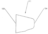
도 1a 내지 도 1p는 본 발명의 실시예에 따르는 풋플레이트(footplate)의 투시도를 도시하는 도면.
도 2a는 본 발명의 실시예에 따라, 전개 장치(deployment device)의 완전히 조립된 우측면 투시도를 도시하는 도면.
도 2b는 본 발명의 실시예에 따라, 전개 장치가 부분적으로 노출된 우측면 투시도를 도시하는 도면.
도 3a는 본 발명의 실시예에 따라, 전개 장치가 부분적으로 노출된 우측면 투시도를 도시하는 도면.
도 3b는 본 발명의 실시예에 따라, 도 3a의 전개 장치 일부분을 확대한 창(window)을 도시하는 도면.
도 4a는 본 발명의 실시예에 따라, 전개 장치 중 원위 부분의 투시도를 도시하는 도면.
도 4b는 본 발명의 실시예에 따라, 도 4a의 전개 장치의 일부분을 확대한 창을 도시하는 도면.
도 5a 내지 도 5f는 본 발명의 실시예에 따라, 플러그(plug)의 투시도를 도시하는 도면.
도 6a는 본 발명의 실시예에 따라, 부분적으로 노출된 전개 장치의 우측면을 도시하는 도면.
도 6b는 본 발명의 실시예에 따라, 도 6a의 전개 장치를 확대한 창을 도시하는 도면.
도 6c는 본 발명의 실시예에 따라, 부분적으로 노출된 전개 장치의 우측면 투시도을 도시하는 도면.
도 7a는 본 발명의 실시예에 따라, 부분적으로 노출된 전개 장치의 상단면 투시도를 도시하는 도면.
도 7b는 본 발명의 실시예에 따라, 전개 장치의 일부분을 확대한 창을 도시하는 도면.
도 7c는 본 발명의 실시예에 따라, 전개 장치의 일부분을 확대한 창을 도시하는 도면.
도 8은 본 발명의 실시예에 따라, 부분적으로 노출된 전개 장치 중 원위 단부의 투시도를 도시하는 도면.
도 9a는 본 발명의 실시예에 따라, 전개 장치 중 원위 단부의 투시도를 도시하는 도면.
도 9b는 본 발명의 실시예에 따라, 도 9a에 있어 전개 장치의 일부분을 확대한 창을 도시하는 도면.
도 9c는 본 발명의 실시예에 따라, 전개 장치 중 원위 단부의 비스듬하게 절단된 투시도(cutaway perspective view)를 도시하는 도면.
도 9d는 본 발명의 실시예에 따라, 플러그 경로를 허용하면서 원위 C형-튜브 중 일부분의 부분적인 확대(expansion)를 도시하는 투시도.
도 10a는 본 발명의 실시예에 따라, 부분적으로 노출된 전개 장치의 단면(section) 중 우측면 투시도를 도시하는 도면.
도 10b는 본 발명의 실시예에 따라, 도 10a의 전개 장치 중 일부분을 확대한 창을 도시하는 도면.
도 11은 본 발명의 실시예에 따라, 부분적으로 노출된 전개 장치 단면의 우측면 투시도를 도시하는 도면.
도 12는 본 발명의 실시예에 따라, 부분적으로 노출된 전개 장치 단면의 우측면 투시도를 도시하는 도면.
도 13은 본 발명의 실시예에 따라, 부분적으로 노출된 전개 장치 단면의 우측면 투시도를 도시하는 도면.
도 14는 본 발명의 실시예에 따라, 부분적으로 노출된 전개 장치 단면의 우측면 투시도를 도시하는 도면.
도 15a는 본 발명의 실시예에 따라, 부분적으로 노출된 전개 장치의 우측면 투시도를 도시하는 도면.
도 15b는 본 발명의 실시예에 따라, 도 15a의 전개 장치 중 일부분을 확대한 창을 도시하는 도면.
도 16은 본 발명의 실시예에 따라, 부분적으로 노출된 전개 장치 단면의 우측면 투시도를 도시하는 도면.
도 17a는 본 발명의 실시예에 따라, 부분적으로 노출된 전개 장치의 우측면 투시도를 도시하는 도면.
도 17b는 본 발명의 실시예에 따라, 부분적으로 노출된 전개 장치 중 단면의 우측면 투시도를 도시하는 도면.
도 18은 본 발명의 실시예에 따라, 부분적으로 노출된 전개 장치의 우측면 투시도를 도시하는 도면.
도 19는 본 발명의 실시예에 따라, 부분적으로 노출된 전개 장치 단면의 우측면 투시도를 도시하는 도면.
도 20은 본 발명의 실시예에 따라, 부분적으로 노출된 전개 장치 단면의 상단면 투시도를 도시하는 도면.
도 21a는 본 발명의 실시예에 따라, 부분적으로 노출된 전개 장치 단면의 우측부 횡단면을 도시하는 도면.
도 21b는 본 발명의 실시예에 따라, 부분적으로 노출된 전개 장치 단면의 상단 측부 횡단면을 도시하는 도면.
도 21c 와 도 21d는 본 발명의 실시예에 따라, 도 21a의 전개 장치 중 일부분을 확대한 창을 도시하는 도면.
도 22a는 본 발명의 실시예에 따라, 부분적으로 노출된 전개 장치 단면의 우측부 횡단면을 도시하는 도면.
도 22b는 본 발명의 실시예에 따라, 부분적으로 노출된 전개 장치 단면 중 상단 측부 횡단면을 도시하는 도면.
도 22c와 도 22d는 본 발명의 실시예에 따라, 도 22b의 전개 장치 중 일부분을 확대한 창을 도시하는 도면.
도 22e는 본 발명의 실시예에 따라, 도 22a의 전개 장치 중 일부분을 확대한 창을 도시하는 도면.
도 23a는 본 발명의 실시예에 따라, 부분적으로 노출된 전개 장치 단면의 우측부 횡단면을 도시하는 도면.
도 23b는 본 발명의 실시예에 따라, 부분적으로 노출된 전개 장치 단면의 상단 측부 횡단면을 도시하는 도면.
도 23c와 도 23d는 본 발명의 실시예에 따라, 도 23b의 전개 장치 중 일부분을 확대한 창을 도시하는 도면.
도 23e는 본 발명의 실시예에 따라, 도 23a의 전개 장치 중 일부분을 확대한 창을 도시하는 도면.
도 23e는 본 발명의 실시예에 따라, 부분적으로 노출된 전개 장치 단면의 우측부 횡단면을 도시하는 도면.
도 24a는 본 발명의 실시예에 따라, 부분적으로 노출된 전개 장치 단면의 우측부 횡단면을 도시하는 도면.
도 24b는 본 발명의 실시예에 따라, 부분적으로 노출된 전개 장치 단면의 상단 측부 횡단면을 도시하는 도면.
도 24c 내지 도 24f는 본 발명의 실시예에 따라, 도 24b의 전개 장치 중 일부분을 확대한 창을 도시하는 도면.
도 25a는 본 발명의 실시예에 따라, 부분적으로 노출된 전개 장치 단면의 우측부 횡단면을 도시하는 도면.
도 25b는 본 발명의 실시예에 따라, 부분적으로 노출된 전개 장치 단면의 상단 측부 횡단면을 도시하는 도면.
도 25c 내지 도 25d는 본 발명의 실시예에 따라, 도 25b의 전개 장치 중 일부분을 확대한 창을 도시하는 도면.
도 26a는 본 발명의 실시예에 따라, 부분적으로 노출된 전개 장치 단면의 우측부 횡단면을 도시하는 도면.
도 26b는 본 발명의 실시예에 따라, 부분적으로 노출된 전개 장치 단면의 상단 측부 횡단면을 도시하는 도면.
도 26d와 도 26f는 본 발명의 실시예에 따라, 도 26a의 전개 장치 중 일부분을 확대한 창을 도시하는 도면.
도 26g는 본 발명의 실시예에 따라, 도 26a의 전개 장치 중 일부분에 걸쳐서 확대된 수직 횡단면을 도시하는 도면.
도 26c와 도 26e는 본 발명의 실시예에 따라, 도 26b의 전개 장치 중 일부분을 확대한 창을 도시하는 도면.
도 27은 본 발명의 실시예에 따라, 부분적으로 노출된 전개 장치 단면의 좌측면 투시도를 도시하는 도면.
도 28a는 본 발명의 실시예에 따라, 부분적으로 노출된 전개 장치 단면의 좌측부 횡단면을 도시하는 도면.
도 28b는 본 발명의 실시예에 따라, 전개 장치의 하단 측면 투시도를 도시하는 도면.
도 29a는 본 발명의 실시예에 따라, 부분적으로 노출된 전개 장치 단면의 우측부 횡단면을 도시하는 도면.
도 29b는 본 발명의 실시예에 따라, 부분적으로 노출된 전개 장치 단면의 상단 측부 횡단면을 도시하는 도면.
도 29d, 도 29e 및 도 29f는 본 발명의 실시예에 따라, 도 29a의 전개 장치 일부분을 확대한 창을 도시하는 도면.
도 29c는 본 발명의 실시예에 따라, 도 29a의 전개 장치 일부분에 걸쳐서 확대된 수직 횡단면을 도시하는 도면.
도 30a는 본 발명의 실시예에 따라, 부분적으로 노출된 전개 장치 단면의 우측부 횡단면을 도시하는 도면.
도 30b 내지 도 30c는 본 발명의 실시예에 따라, 도 30a의 전개 장치 일부분을 확대한 창을 도시하는 도면.
도 31 내지 도 41은 본 발명의 실시예에 따라, 혈관을 통하여 형성된 개구부를 봉합하기 위한 봉합 장치를 배치하기 위하여 전개 장치를 사용하는 연속적인 단계를 도시하는 도면.
도 42 내지 도 43은 본 발명의 실시예에 따라, 혈관을 통하여 형성된 개구부와 봉합 관계(즉, 사후-봉합 장치(post-closure device) 전개 형상 및 위치)에 있는 봉합 장치를 도시하는 도면.The invention can be more fully understood and appreciated by the more detailed description that accompanies the accompanying drawings, in which the drawings are as follows.
1A-1P illustrate perspective views of a footplate according to an embodiment of the invention.
2A shows a fully assembled right side perspective view of a deployment device, in accordance with an embodiment of the invention.
FIG. 2B illustrates a right side perspective view of a deployment device partially exposed, in accordance with an embodiment of the invention. FIG.
3A illustrates a right side perspective view of a partially deployed deployment device, in accordance with an embodiment of the invention.
FIG. 3B illustrates an enlarged view of a portion of the deployment device of FIG. 3A, in accordance with an embodiment of the invention. FIG.
4A shows a perspective view of a distal portion of a deployment device, in accordance with an embodiment of the invention.
FIG. 4B illustrates an enlarged window of a portion of the deployment device of FIG. 4A, in accordance with an embodiment of the invention. FIG.
5A-5F illustrate a perspective view of a plug, in accordance with an embodiment of the invention.
6A illustrates the right side of a partially exposed deployment device, in accordance with an embodiment of the invention.
FIG. 6B illustrates an enlarged window of the deployment device of FIG. 6A, in accordance with an embodiment of the present invention. FIG.
FIG. 6C illustrates a right side perspective view of a partially exposed deployment device, in accordance with an embodiment of the invention. FIG.
FIG. 7A shows a top perspective view of a partially exposed deployment device, in accordance with an embodiment of the invention. FIG.
FIG. 7B illustrates an enlarged window of a portion of a deployment device, in accordance with an embodiment of the present invention. FIG.
7C illustrates an enlarged window of a portion of the deployment device, in accordance with an embodiment of the present invention.
8 illustrates a perspective view of the distal end of a partially exposed deployment device, in accordance with an embodiment of the invention.
9A illustrates a perspective view of the distal end of a deployment device, in accordance with an embodiment of the present invention.
FIG. 9B illustrates an enlarged window of a portion of the deployment device in FIG. 9A, in accordance with an embodiment of the invention. FIG.
9C illustrates an obliquely cutaway perspective view of the distal end of the deployment device, in accordance with an embodiment of the present invention.
FIG. 9D is a perspective view showing partial expansion of a portion of the distal C-tube while allowing a plug path, in accordance with an embodiment of the present invention. FIG.
10A shows a right side perspective view of a section of a partially exposed deployment device, in accordance with an embodiment of the invention.
FIG. 10B illustrates an enlarged window of a portion of the deployment device of FIG. 10A, in accordance with an embodiment of the invention. FIG.
FIG. 11 illustrates a right side perspective view of a partially exposed deployment device cross section, in accordance with an embodiment of the present invention. FIG.
12 is a right side perspective view of a partially exposed deployment device cross-section, in accordance with an embodiment of the invention.
FIG. 13 illustrates a right side perspective view of a partially exposed deployment device cross section, in accordance with an embodiment of the present invention. FIG.
FIG. 14 illustrates a right side perspective view of a partially exposed deployment device cross section, in accordance with an embodiment of the present invention. FIG.
15A illustrates a right side perspective view of a partially exposed deployment device, in accordance with an embodiment of the present invention.
FIG. 15B illustrates an enlarged window of a portion of the deployment device of FIG. 15A, in accordance with an embodiment of the invention. FIG.
FIG. 16 shows a right side perspective view of a partially exposed deployment device cross section, in accordance with an embodiment of the present invention. FIG.
FIG. 17A illustrates a right side perspective view of a partially exposed deployment device, in accordance with an embodiment of the present invention. FIG.
FIG. 17B illustrates a right side perspective view of the cross section of a partially exposed deployment device, in accordance with an embodiment of the invention. FIG.
18 shows a right side perspective view of a partially exposed deployment device, in accordance with an embodiment of the invention.
19 shows a right side perspective view of a partially exposed deployment device cross section, in accordance with an embodiment of the present invention.
20 shows a top perspective view of a partially exposed deployment device cross section, in accordance with an embodiment of the present invention.
FIG. 21A illustrates a right side cross-section of a partially exposed deployment device cross section, in accordance with an embodiment of the invention. FIG.
FIG. 21B illustrates a top side cross section of a partially exposed deployment device cross section, in accordance with an embodiment of the invention. FIG.
21C and 21D illustrate an enlarged window of a portion of the deployment device of FIG. 21A, in accordance with an embodiment of the invention.
FIG. 22A illustrates a right side cross section of a partially exposed deployment device cross section, in accordance with an embodiment of the invention. FIG.
FIG. 22B illustrates a top side cross section of a partially exposed deployment device cross section, in accordance with an embodiment of the invention. FIG.
22C and 22D show an enlarged window of a portion of the deployment device of FIG. 22B, in accordance with an embodiment of the invention.
FIG. 22E illustrates an enlarged window of a portion of the deployment device of FIG. 22A, in accordance with an embodiment of the invention. FIG.
FIG. 23A illustrates a right side cross-section of a partially exposed deployment device cross section, in accordance with an embodiment of the invention. FIG.
FIG. 23B illustrates a top side cross section of a partially exposed deployment device cross section, in accordance with an embodiment of the invention. FIG.
23C and 23D show enlarged windows of a portion of the deployment device of FIG. 23B, in accordance with an embodiment of the invention.
FIG. 23E illustrates an enlarged window of a portion of the deployment device of FIG. 23A, in accordance with an embodiment of the invention. FIG.
FIG. 23E illustrates a right side cross section of a partially exposed deployment device cross section, in accordance with an embodiment of the invention. FIG.
FIG. 24A illustrates a right side cross-section of a partially exposed deployment device cross section, in accordance with an embodiment of the invention. FIG.
24B illustrates a top side cross section of a partially exposed deployment device cross section, in accordance with an embodiment of the invention.
24C-24F illustrate an enlarged window of a portion of the deployment device of FIG. 24B, in accordance with an embodiment of the invention.
FIG. 25A illustrates a right side cross section of a partially exposed deployment device cross section, in accordance with an embodiment of the invention. FIG.
FIG. 25B illustrates a top side cross section of a partially exposed deployment device cross section, in accordance with an embodiment of the invention. FIG.
25C-25D illustrate an enlarged window of a portion of the deployment device of FIG. 25B, in accordance with an embodiment of the invention.
FIG. 26A illustrates a right side cross section of a partially exposed deployment device cross section, in accordance with an embodiment of the invention. FIG.
FIG. 26B illustrates a top side cross section of a partially exposed deployment device cross section, in accordance with an embodiment of the invention. FIG.
26D and 26F illustrate an enlarged window of a portion of the deployment device of FIG. 26A, in accordance with an embodiment of the invention.
FIG. 26G illustrates an enlarged vertical cross section over a portion of the deployment device of FIG. 26A, in accordance with an embodiment of the invention. FIG.
26C and 26E illustrate an enlarged window of a portion of the deployment device of FIG. 26B, in accordance with an embodiment of the invention.
FIG. 27 shows a left side perspective view of a partially exposed deployment device cross section, in accordance with an embodiment of the present invention. FIG.
FIG. 28A illustrates a left side cross-section of a partially exposed deployment device cross section, in accordance with an embodiment of the present invention. FIG.
28B illustrates a bottom side perspective view of the deployment device, in accordance with an embodiment of the present invention.
FIG. 29A illustrates a right side cross section of a partially exposed deployment device cross section, in accordance with an embodiment of the invention. FIG.
FIG. 29B illustrates a top side cross section of a partially exposed deployment device cross section, in accordance with an embodiment of the invention. FIG.
29D, 29E, and 29F illustrate an enlarged window portion of the deployment device of FIG. 29A, in accordance with an embodiment of the invention.
FIG. 29C illustrates an enlarged vertical cross section over a portion of the deployment device of FIG. 29A, in accordance with an embodiment of the invention. FIG.
30A shows a right side cross section of a partially exposed deployment device cross section, in accordance with an embodiment of the present invention.
30B-30C illustrate an enlarged window portion of the deployment device of FIG. 30A, in accordance with an embodiment of the invention.
31-41 illustrate successive steps of using the deployment device to place a closure device for closing an opening formed through a blood vessel, in accordance with an embodiment of the present invention.
42-43 illustrate a closure device in a closure relationship (ie, post-closure device deployment shape and position) with an opening formed through a blood vessel, in accordance with an embodiment of the present invention.
본 발명은 이제 첨부된 도면들을 예시하는 본 발명의 바람직한 실시예들의 예들에서 상세하게 설명될 것이다.The invention will now be described in detail in examples of preferred embodiments of the invention illustrating the accompanying drawings.
본 발명의 한 실시예에 따르면, 봉합 장치(100)는, 출혈(또는 그 외 생체학적 유체 또는 조직의 흐름)을 조절하기 위해(또는 방지하거나 또는 중지시키기 위해), 풋플레이트(110)(이 풋플레이트는 풋플레이트의 임의의 실시예들을 포함할 수 있으며, 이는 하기에서 기술될 것임), 플러그(111), 및 생체 조직을 통해 형성된 개구부, 가령, 경피 형성 천자(이 천자는 혈관벽을 통해 형성되는 개구부와 생체조직을 통해 형성되는 개구부와 접촉하는 조직계를 포함하며, 이는 혈관 위에 둘러싸고 있는 피부와 조직을 통해 연장됨)를 봉합 또는 밀폐하도록 사용되고 제공될 수 있는 와이어(120), 절개부(incision), 또는, 혈관, 장기 또는 이와 유사한 것들과 같은 생체 조직을 통해 형성된 그 외 다른 타입의 개구부를 포함한다. 예를 들어, 본 발명의 한 실시예의 봉합 장치(100)는 동맥절개부(arteriotomy)를 봉합하도록 사용될 수 있는데, 이 동맥절개부는 대퇴부 동맥과 같은 동맥에서 절개부이거나 또는 개구부(opening)이며 그리고 진단 또는 치료 혈관내수술 동안 의사에 의해 경피 형성 천자(percutaneeously formed puncture)(혈관 바로 위의 피부와 조직을 통하는 개방조직계(open tissue tract))와 공동으로 형성되는 동맥절개를 봉합하도록 사용될 수 있다.According to one embodiment of the present invention, the suture device 100 includes a foot plate 110 (to prevent (or prevent or stop) bleeding (or other flow of biological fluid or tissue)). The footplate may include any embodiments of the footplate, which will be described below), a
본 발명의 한 실시예에 따르면, 봉합 장치(100)는 사전-전개 봉합 장치 전개 형상 및 위치가 되거나 또는 사후-혈관(post-vascular) 봉합 장치 전개 형상 및 위치가 될 수 있다. 사전-전개 봉합 장치 전개 형상 및 위치는 봉합 장치(100)가 본 발명의 한 실시예의 전개 장치(200) 내부에 안착될 때의 형상과 위치를 포함한다(이 전개 장치(200)는 혈액이 개구부를 통해 흐르는 것을 중지시키기 위해 봉합 장치(100)가 혈관을 봉합하도록, 예를 들어 혈관벽 내의 개구부 내로 전개시키도록 사용된다). 사후-혈관 봉합 장치 전개 형상 및 위치는 봉합 장치(100)가 혈관벽 내의 개구부 내에 그리고 개구부를 통과하는 형상 및 위치를 포함한다.According to one embodiment of the invention, the suture device 100 may be a pre-deployment closure device deployment shape and position or a post-vascular closure device deployment shape and position. The pre-deployment closure device deployment shape and position includes the shape and location when the closure device 100 rests within the
봉합 장치(100), 사전-전개 및 사후-혈관 봉합 장치 전개 형상 및 위치, 전개 장치(200), 및 혈관벽 내의 개구부를 봉합하기 위해 봉합 장치(100)를 전개하는 방법은 도면들을 참조하여 밑에서 더욱 상세하게 기술된다.The method of deploying the closure device 100 to seal the closure device 100, pre-development and post-vessel closure device deployment shape and location, the
본 발명의 전반에 걸쳐 유사한 도면부호들이 유사한 부분들을 가리키는 도면들을 참조할 때, 도 1a는 본 발명의 한 실시예에 따른 풋플레이트(110)를 도시한다. 이 실시예에는 사전-전개 봉합 장치 전개 형상 및 위치에서의 풋플레이트(110)가 도시되는데, 여기서 이 풋플레이트(110)는 전개 장치(200)의 원위 단부 내에 있다(전개 장치(200)는 도시되지 않음). 풋플레이트(110)는 신장된 U자형 루프(30)를 나타내는 신장된 형상으로 굽어진 (모노리식 구조를 가진) 와이어(120)의 단일 길이의 원위부를 포함한다. 신장된 U자형 루프(30)는 개방 근위 단부(101), 닫힌 원위 단부(102), 및 한 쌍의 종방향으로 옆으로 이격되어 연장된 레그(31, 32)를 포함한다. 닫힌 원위 단부(102)와 한 쌍의 종방향으로 옆으로 이격되어 연장된 레그(31, 32)는 공통의 평면 내에서 실질적으로 공면을 형성하며(coplanar) 전개 장치(200)의 컨트롤 하우징(210)의 종축에 실질적으로 평행하게 형성된다. 신장된 U자형 루프(30)의 닫힌 원위 단부(102)는 굽어진 와이어 신장 형상의 종방향 원위 단부를 형성한다. 신장된 U자형 루프의 한 쌍의 종방향으로-연장된 옆으로 이격된 레그(31, 32)는 신장된 U자형 루프의 개방 근위 단부에 위치된 자유 근위 단부를 가진 자유레그(31), 및 연결레그(32)를 포함한다. 나선형 연결부(33)는 와이어(120)에 연결된다. 나선형 연결부(33)는 굽힘 영역(bending region)에서 영구적으로(소성적으로) 변형하도록 작동가능하다. 와이어(120)는 컨트롤 하우징(210)의 종축에 대해 축방향으로 구성된다. 와이어(120)는 풋플레이트(110)에 근접하게 위치되며 나선형 연결부(33)는 신장된 U자형 루프(30)의 개방 근위 단부(101)에서 와이어(120)와 결합레그(34)(이 결합레그(34)는 종방향으로-연장되는 옆으로 이격된 레그(31, 32)과 실질적으로 공면으로 형성됨) 사이에서 연장된다.Referring to the drawings in which like reference numerals refer to like parts throughout the invention, FIG. 1A shows a
도 1b에서, 본 발명의 한 실시예에 따른 풋플레이트(110)가 예시된다. 이 실시예는 사후-전개 봉합 장치 전개 형상 및 위치에서의 (도 1a의) 풋플레이트(110)를 도시하는데, 상기 풋플레이트(110)의 한 부분은 그 내부의 경피 천자(도시되지 않음) 밑에서 혈관(예를 들어, 동맥, 도시되지 않음)의 내측벽에 대해 안착된다(seated). 나선형 연결부(33)은 굽힘 영역을 포함하는데, 이 굽힘 영역은 영구적으로(소성적으로) 변형된다. 닫힌 원위 단부(102)와 한 쌍의 종방향으로 옆으로 이격되어 연장된 레그(31, 32)는 공통 평면에서 실질적으로 공면을 형성하며, 천자의 종축에 대해 실질적으로 수직이고 혈관의 내측벽의 평면에 대해 실질적으로 평행하게 형성된다. 와이어(120)는 나선형 연결부(33)로부터 혈관벽 내의 개구부를 통해 조직계로 근위 방향으로 연장되는데(extend proximall), 여기서 와이어(120)는 (전개 장치(200)에 의해 절단되고 굽혀지기 전에) 천자의 종축에 대해 축방향으로 구성된다.In FIG. 1B,
도 1c에서, 본 발명의 한 실시예에 따른 풋플레이트가 예시된다. 이 실시예에는 사전-전개 봉합 장치 전개 형상 및 위치에 있는 풋플레이트(110')가 도시되는데, 여기서 이 풋플레이트(110')는 전개 장치(200)(도시되지 않음)의 원위 단부 내에 있다. 풋플레이트(110')는 신장된 U자형 루프(30')를 나타내는 신장된 형상으로 굽어진 (모노리식 구조를 가진) 와이어(120)의 단일 길이의 원위부를 포함한다. 신장된 U자형 루프(30')는 닫힌 근위 단부(101'), 개방 원위 단부(102'), 및 한 쌍의 종방향으로 옆으로 이격되어 연장된 레그(31', 32')를 포함한다. 신장된 U자형 루프(30')의 닫힌 근위 단부(101')는 굽어진 와이어 신장 형상의 종방향 근위 단부를 형성한다. 신장된 U자형 루프(30')의 한 쌍의 종방향으로-연장된 옆으로 이격된 레그는 신장된 U자형 루프(30)의 개방 원위 단부(102')에 위치된 자유 원위 단부를 가진 자유레그(31'), 및 연결레그(32')를 포함한다. 아치형으로-만곡된 연결부(33'), 및 굽힘 영역을 포함하는 중앙레그(34')가 도시된다. 아치형으로-만곡된 연결부(33')는 굽어진 와이어 형상의 종방향 원위 단부를 형성하는, 개방 원위 단부(102')에서 중앙레그(34')와 연결레그(34') 사이에서 연장된다. 신장된 U자형 루프(30')와 아치형으로-만곡된 연결부(33')는 공통 평면에서 실질적으로 공면을 형성하며 전개 장치(200)의 컨트롤 하우징(210)의 종축에 대해 축방향으로 형성된다. 아치형으로-만곡된 연결부(33')는 자유레그(31')와 연결레그(32') 사이에서 연결레그(32')를 향해 중앙레그(34')로 만곡된다. 각각의 자유레그(31')와 연결레그(32')는 점용접부(spot weld, 35)에 의해 중앙레그의 원위부분에 고정된다. 상기 점용접부(35)는 전자빔 점용접부 또는 레이저 점용접부를 포함할 수 있다. 자유레그의 원위 단부는 자유레그가 중앙레그(34')에 점용접되는 지점에서 끝을 이룬다(하지만 이보다 길 수도 짧을 수도 있다). 중앙레그(34')는 닫힌 근위 단부(101') 밑에서 연장되고(하지만 이를 초과하여 연장될 수도 있음) 상기 근위 단부(101')를 향해 근위 방향으로 연장되며, 그리고 공통 평면으로부터 와이어(120)로의 각도에서 닫힌 근위 단부(101')를 초과하여 연장되는데, 여기서 와이어(120)는 풋플레이트(110')에 대해 근접하게 위치된다.In FIG. 1C, a footplate according to one embodiment of the invention is illustrated. This embodiment shows a footplate 110 'in pre-deployment closure device deployment shape and location, where the footplate 110' is in the distal end of the deployment device 200 (not shown). Footplate 110 'includes a single length distal portion of wire 120 (with monolithic structure) bent in an elongated shape representing elongated U-shaped loop 30'. The elongated U-shaped loop 30 'includes a closed proximal end 101', an open distal end 102 ', and a pair of longitudinally spaced laterally extending
도 1d에서, 본 발명의 한 실시예에 따른 풋플레이트(110')가 예시된다. 이 실시예는 사후-전개 봉합 장치 전개 형상 및 위치에서의 도 1c의 풋플레이트(110')를 도시하는데, 여기서 상기 풋플레이트(110')의 한 부분은 그 내부의 경피 천자(도시되지 않음) 밑에서 혈관(예를 들어, 동맥, 도시되지 않음)의 내측벽에 대해 안착된다. 굽힘 영역(바람직한 실시예에서 중앙레그(34') 내의 점용접부(35)의 근위 가장자리 부분)은 영구적으로(소성적으로) 변형된다. 신장된 U자형 루프(30')와 아치형으로-만곡된 연결부(33')는 공통 평면에서 실질적으로 공면을 형성하는 것을 유지하며, 천자의 종축에 대해 실질적으로 수직이고 혈관의 내측벽의 평면에 대해 실질적으로 평행하게 형성된다. 와이어(120)는 굽힘 영역으로부터 혈관벽 내의 개구부를 통해 그리고 조직계 내부로 근위 방향으로 연장되는데, 여기서 와이어(120)는 (전개 장치(200)에 의해 절단되고 굽혀지기 전에) 천자의 종축에 대해 축방향으로 구성된다.In FIG. 1D,
도 1e-1f에서, 본 발명의 한 실시예에 따른 풋플레이트(710)가 도시된다. 이 풋플레이트의 실시예들은 자유레그(731)와 점용접부(735)를 제외하고는 각각 도 1c-1d에 예시된 풋플레이트들과 유사하다. 도 1e와 도 1f에 도시된 바와 같이, 자유레그(731)는 후크식 원위 단부를 포함하며, 점용접부(735)는 오직 중앙레그(734)를 연결레그(732)에 고정시킨다. 또한, 신장된 U자형 루프(730), 근위 단부(1101)와 원위 단부(1102), 및 아치형으로-만곡된 연결부(733)도 도시된다.1E-1F,
도 1g에서, 본 발명의 한 실시예에 따른 풋플레이트(810)가 도시된다. 이 실시예에는 사전-전개 봉합 장치 전개 형상 및 위치에 있는 풋플레이트(810)가 도시되는데, 여기서 이 풋플레이트(810)는 전개 장치(200)(도시되지 않음)의 원위 단부 내에 있다. 풋플레이트(810)는 종방향으로 형성된 블록 또는 바(837)이다. 상기 바(837)는 종방향 구멍(aperture, 840), 아치형 상측표면(838), 아치형 바닥표면(도시되지 않음)(대안으로, 상측 및 바닥표면들은 실질적으로 평면으로 구성될 수 있음), 주변의 측면표면(839), 근위 단부(2101) 및 원위 단부(1202)를 포함한다. 와이어(120)는 평평한 또는 코인형(coined) 원위 단부(836)에 의해 바(837)에 연결되며(용접되는 것이 바람직함), 이 원위 단부(836)는 바(837)의 아치형 상측표면(838)의 원위 단부(2102)에 연결된다. 코인형 원위 단부(836)는 중앙부(834)로 근위 방향으로 연장되며, 이 중앙부(834)는 구멍(840)를 통해 연장되고 근위 단부(2101) 밑에서 근위 방향으로 연장된다(하지만 이를 초과하여 연장될 수도 있음).1G,
도 1h에서, 본 발명의 한 실시예에 따른 풋플레이트(810)가 예시된다. 이 실시예는 사후-전개 봉합 장치 전개 형상 및 위치에서의 도 1g의 풋플레이트(810)를 도시하는데, 여기서 상기 풋플레이트(810)의 한 부분은 그 내부의 경피 천자(도시되지 않음) 밑에서 혈관(예를 들어, 동맥, 도시되지 않음)의 내측벽에 대해 안착된다. 중앙부(834)는 굽힘 영역을 포함하는데, 이 굽힘 영역은 영구적으로(소성적으로) 변형된다. 중앙부(834)는 구멍(840)을 통해 근위 방향으로 연장된다. 와이어(120)는 중앙부(834)로부터 혈관벽 내의 개구부를 통해 조직계 내부로 근위 방향으로 연장되는데, 여기서 와이어(120)는 (전개 장치(200)에 의해 절단되고 굽혀지기 전에) 천자의 종축에 대해 동축으로 구성된다(coaxial).In FIG. 1H, a
도 1i-1j에서, 본 발명의 한 실시예에 따른 풋플레이트(1010)가 도시된다. 이 풋플레이트의 실시예들은 와이어(120)의 원위 단부(1036)를 제외하고는 각각 도 1g-1h에 예시된 풋플레이트들과 유사하다. 원위 단부(1036)는 평평하지도 또는 코인형으로 구성되지도 않는다(하지만 외이어의 나머지 부분과 같은 동일한 원형의 횡단면을 가진다). 와이어(120)는 풋플레이트(1010)의 바(1037)의 원위 단부(4102)에서 아치형 상측표면(1038)과 와이어(120)의 원위 단부 사이의 종방향 경계면(interface)을 따라 양 측면 위에 고정된다(용접되는 것이 바람직하다). 또한, 근위 단부(4101), 중앙부(1034), 구멍(1040), 및 주변의 측면표면(1039)도 도시된다.1I-1J,
도 1k에서, 본 발명의 한 실시예에 따른 풋플레이트(910)의 상부 투시도가 도시된다. 이 실시예에는 사전-전개 봉합 장치 전개 형상 및 위치에 있는 풋플레이트(910)가 도시되는데, 여기서 이 풋플레이트(910)는 전개 장치(200)(도시되지 않음)의 원위 단부 내에 있다. 풋플레이트(910)는 종방향으로 형성된 블록 또는 바(937)이다. 상기 바(837)는 실질적으로 평면인 상측표면(938), 실질적으로 평면인 바닥표면(도시되지 않음), 주변의 측면표면(939), 근위 단부(3101) 및 원위 단부(3102)를 포함한다. 와이어(120)는 볼형(ball-shaped) 단부(936)에 의해 바(937)에 연결되며, 이 볼형 단부(936)는 바(937)의 평면 상측표면(938)의 소켓(941)에 연결된다(또한 평면 바닥표면에 연결될 수도 있음). 소켓(941)은 도 1l에 도시된 바와 같이 C자 형태로 구성되어 풋플레이트(910)가 시동되게(actuation) 할 수 있다. 와이어(120)의 한 부분은 바(937)의 상측표면(938)의 아치형 함몰부(942) 내에 위치될 수 있다.In FIG. 1K, a top perspective view of a
도 1l에서, 본 발명의 한 실시예에 따른 풋플레이트(910)의 바닥 투시도가 도시된다. 이 실시예는 사후-전개 봉합 장치 전개 형상 및 위치에서의 도 1i의 풋플레이트(910)를 도시하는데, 여기서 상기 풋플레이트(910)의 한 부분은 그 내부의 경피 천자(도시되지 않음) 밑에서 혈관(예를 들어, 동맥, 도시되지 않음)의 내측벽에 대해 안착된다. 이 실시예의 풋플레이트(910) 내에는 굽힘 영역이 없다. 바(937)는 볼(936)과 소켓(941) 형상/메커니즘에 따라 회전하도록 작동가능하다. 이에 따라 근위 단부(3101)가 원위방향으로 밑으로 회전하는 회전지점이 형성되며 원위 단부(3102)는 상기 형성된 회전지점 주위로 근위방향으로 위로 회전한다(대안으로, 대안의 형상으로는, 반대방향으로 회전할 수도 있음). 도 1l은 완전히 작동 또는 회전된 위치에 있는 풋플레이트(910)를 도시한다. 와이어(120)는 볼(936)로부터 혈관벽 내의 개구부를 통해 조직계로 근위 방향으로 연장되는데, 여기서 와이어(120)는 (전개 장치(200)에 의해 절단되고 굽혀지기 전에) 천자(도시되지 않음)의 종축에 대해 축방향으로 구성된다. 실질적으로 평면인 바닥표면(943)이 도시되는데, 이 바닥표면(943)은 바(937)의 상측표면(938)의 함몰부(942)의 바닥부를 포함하는 돌출부를 추가로 포함할 수 있다.In FIG. 1L, a bottom perspective view of a
도 1m에서, 본 발명의 한 실시예에 따른 풋플레이트(1110)의 상부 투시도가 도시된다. 이 실시예에는 사전-전개 봉합 장치 전개 형상 및 위치에 있는 풋플레이트(1110)가 도시되는데, 여기서 이 풋플레이트(1110)는 전개 장치(200)(도시되지 않음)의 원위 단부 내에 있다. 풋플레이트(1110)는 종방향으로 형성된 블록 또는 바(1137)이다. 바(1137)는 y자 형태이며 상기 바(1137)는 실질적으로 평면인 상측표면(1138), 실질적으로 평면인 바닥표면(1143)(도시되지 않음), 주변의 측면표면(1139), 근위 단부(5101), 원위 단부(5102) 및 슬롯(1146)에 의해 분리된 두 개의 근위 방향으로 연장되는 실질적으로 공통평면에 형성된 레그(1144 및 1145)를 포함한다. 와이어(120)는 후크형 단부(1136)를 포함하는 힌지 메커니즘에 의해 바(1137)에 연결되며, 이 후크형 단부(1136)는 바(1137)의 실질적으로 평면인 상측표면(1138)에 부착된 반원부(1141)에 연결된다(또한 평면 바닥표면에 연결될 수도 있음).In FIG. 1M, a top perspective view of
도 1n에서, 본 발명의 한 실시예에 따른 풋플레이트(1110)의 바닥 투시도가 도시된다. 이 실시예는 사후-전개 봉합 장치 전개 형상 및 위치에서의 도 1m의 풋플레이트(1110)를 도시하는데, 여기서 상기 풋플레이트(1110)의 한 부분은 그 내부의 경피 천자(도시되지 않음) 밑에서 혈관(예를 들어, 동맥, 도시되지 않음)의 내측벽에 대해 안착된다. 이 실시예의 풋플레이트(1110) 내에는 굽힘 영역이 없다. 바(1137)는 힌지 메커니즘에 따라 회전하도록 작동가능하며, 이에 따라 근위 단부(5101)가 원위방향으로 밑으로 회전하는 회전지점이 형성되며 원위 단부(5102)는 상기 형성된 회전지점 주위로 근위방향으로 위로 회전한다(대안으로, 대안의 형상으로는, 반대방향으로 회전할 수도 있음). 도 1n은 완전히 작동 또는 회전된 위치에 있는 풋플레이트(1110)를 도시한다. 와이어(120)는 혈관벽 내의 개구부를 통해 조직계로 근위 방향으로 연장되는데, 여기서 와이어(120)는 (전개 장치(200)에 의해 절단되고 굽혀지기 전에) 천자(도시되지 않음)의 종축에 대해 축방향으로 구성된다. 또한, 실질적으로 평면인 바닥표면(1143)도 도시된다.In FIG. 1N, a bottom perspective view of
도 1o-1p에서, 본 발명의 한 실시예에 따른 풋플레이트(1210)가 도시된다. 이 풋플레이트의 실시예들은 와이어(120)의 후크형 원위 단부(1236) 및 슬롯(1246) 및 구멍(1241)를 통과하는 부속물(attachment)을 제외하고는 각각 도 1m-1n에 예시된 풋플레이트들과 유사하다. 후크형 원위 단부(1236)는 구멍(1241)을 통해 바(1237)에 부착된다. 후크형 원위 단부(1236)는 구멍(1241)을 통해 실질적으로 평면인 바닥표면(1243)으로부터 실질적으로 평면인 상측표면(1238)으로 신장되며, 그 뒤, 슬롯(1246)을 통해 걸려져서(hook) 풋플레이트(1210)를 와이어(120)에 고정시킨다. 또한, 바(1237), 원위 단부(6102)와 근위 단부(6101), 실질적으로 평면인 상측표면(1238), 실질적으로 평면인 바닥표면(1243), 주변의 측면표면(1239), 두 개의 근위 방향으로 연장하는 실질적으로 공통 평면에 형성되는 레그(1244 및 1245), 슬롯(1246), 및 와이어(120)도 도시된다.1O-1P, a
본 발명의 한 실시예에 따르면, 도면들을 참조하여 하기에서 본 발명의 한 실시예의 봉합 장치(100)를 포함하는 전개 장치(200)가 기술된다. 사용할 수 있는 풋플레이트의 예로서, 풋플레이트의 도면부호는 특별히 110'으로 표시된다. 하지만, 풋플레이트(110')를 대신하여, 위에서 언급된 풋플레이트의 도면부호들을 포함하여 임의의 풋플레이트 실시예도 사용될 수 있음을 이해해야 한다.According to one embodiment of the present invention, a
도 2a-4b에서, 본 발명의 한 실시예에 따라서, 근위 단부(10)와 원위 단부(20)를 가진, 전개 장치(200)의 우측면도가 예시된다(도 2a는 완전히 조립된 전개 장치(200)를 도시하며 도 2b, 도 3 및 도 4는 상기 전개 장치(200)의 부분적으로 노출된 도면 즉 전개 장치(200)의 그 외 다른 부분들을 보여주기 위해 생략되어 있는 부분들을 도시한다). 본 발명의 한 실시예에 따르면, 봉합을 필요로 하는 혈관 내로 전개하기 이전에, 풋플레이트(110')는 전개 장치(200)의 원위 단부(20)에 위치되며 외부 원위 C형-튜브(201) 내에 배치되는 반면, 와이어(120)의 나머지 부분은 와이어 페룰(wire ferruel, 250)에서 끝을 이루는 전개 장치(200) 내의 원위 풋플레이트(110')에 근접하게 위치된다(추후 도 7a 참조). 풋플레이트(110')는 전개 장치(200)의 컨트롤 하우징(210)의 종축에 대해 축방향에 있다. 하기와 같이, 풋플레이트(110')의 근위 단부(101)는 내부 원위 C형-튜브(202)의 원위 단부에 접한다(도 4a-4b 참조).2A-4B, a right side view of the
도 5a-f에서, 본 발명의 한 실시예에 따른 플러그(111)가 예시된다. 이 실시예들은 원뿔 형태이며 원위부(또는 원위 단부)(104) 및 근위부(또는 근위 단부)(103)을 포함하는 플러그(111)를 도시하는데, 여기서 플러그의 원위부(104)의 직경은 플러그의 근위부(103)의 직경보다 더 작다. 플러그의 최대지점에서 플러그(111)의 직경은 전개 장치의 주 도관 영역(205)의 직경보다 더 크며, 이는 하기에서 논의될 것이다. 도 5a에서, 플러그(111)의 우측면도가 도시된다. 도 5b에서, 플러그(111)의 상부 측면도가 도시된다. 도 5c에서, 뒤집어진 플러그(111)의 좌측면도가 도시된다. 도 5d에서, 루멘(105)을 포함하는 플러그(111)의 전방 측면도가 도시된다. 도 5e에서, 플러그(111)의 바닥 측면도가 도시된다. 도 5f에서, 루멘(105)을 포함하는 플러그(111)의 후방 측면도가 도시된다. 본 발명의 한 실시예에 따르면, 하나 이상의 컷아웃(cutout) 또는 공동(cavity)이 플러그의 원위 단부에 제공될 수 있으며 이에 따라 플러그(111)가 풋플레이트(110')와 와이어(120)와 함께 배열될 수 있다. 또한, 본 발명의 한 실시예에 따라서, 하나 이상의 컷아웃 또는 공동이 플러그(111)의 근위 단부에 제공될 수 있으며 푸시튜브(212)의 원위 단부 내의 인서트(112)(도 10b 참조)가 풋플레이트(110')에 대해 플러그(111)의 회전조절을 유지하게 할 수 있다. 본 발명의 실시예들에서는, 컷아웃 또는 어떠한 컷아웃도 없는 다양한 조합의 플러그(111)가 고려된다.In Figures 5A-F, a
도 6a-6c에서, 본 발명의 한 실시예에 따른 전개 장치(200)의 부분적으로 노출된 우측면도가 예시된다. 본 발명의 한 실시예에 따르면, 봉합을 필요로 하는 혈관 내로 전개하기 이전에(즉 사전-전개 봉합 장치 전개 형상 및 위치에서), 플러그(111)는 풋플레이트(110')에 근접하게 위치되고 와이어(120)의 종축을 따라 위치된다. 플러그(111)는 전개 장치(200)의 (컨트롤 하우징(210)의 내부에 있는) 외부 근위튜브(211)의 원위부 내측의, 푸시튜브(212)에 원위 방향으로 인접하게 위치된다.6A-6C, a partially exposed right side view of a
도 7a-7c에서, 본 발명의 한 실시예에 따른 전개 장치의 부분적으로 노출된 상부도면이 예시된다. 이 실시예는 전개 장치(200) 내의 와이어(120) 위치를 도시한다. 와이어(120)는 풋플레이트(110')로부터 플러그(111) 내의 종축 홀(105)(도시되지 않음)을 통해 근위방향으로 신장된다. 와이어(120)는 풋플레이트(110')로부터 내부 원위 C형-튜브(202)(도시되지 않음), 및 (푸시튜브(212) 내에 있는) 전단 튜브(sheer tube, 224)를 통해 와이어 페룰(250)의 내부 근위 단부로 신장된다. In FIGS. 7A-7C, a partially exposed top view of a deployment device according to one embodiment of the invention is illustrated. This embodiment shows the location of the
본 발명의 한 실시예에 따르면, 하기에서, 본 발명의 한 실시예의 전개 장치(200)의 사전-전개 봉합 장치 전개 형상(내정 형상)이 전반적으로 원위 단부(20)로부터 근위 단부(10)로 기술될 것이다. 적절한 도면에서, 허용가능한 체결수단(예를 들어, 나사)이 번호(226)로 표시되며 와셔(washer)는 번호(214)로 표시된다. 전개 장치(200)의 사용 방법, 및 사후-전개 봉합 장치 전개 형상 및 위치에 있는 봉합 장치(100)가 하기에서 기술될 것이다.According to one embodiment of the invention, in the following, the pre-deployment closure device deployment shape (internal shape) of the
다시 도 2a-2b에서, 이 실시예들은 외부 원위 C형-튜브(201)를 포함하는 전개 장치(200)를 도시한다. 외부 원위 C형-튜브(201)의 원위 단부는 좁다란 노즈(203) 또는 끝단부분(203)을 포함한다. 이 외부 원위 C형-튜브(201)의 노즈 부분(203)은 풋플레이트(110')(도시되지 않음)를 수용하는 전개 장치의 한 부분이다. 외부 원위 C형-튜브(201)의 나머지 부분은 내부 원위 C형-튜브(202)를 수용하며(도 8 참조), 이 내부 원위 C형-튜브(202)는 바닥 부분에 있는 종방향 개구부(204), 및 와이어(120)를 포함한다. 이 원위 C형-튜브들은 함께 동심적으로 위치되어 주 도관 영역(205)을 형성하며, 이는 하기에서 기술된다.Again in FIGS. 2A-2B, these embodiments show a
도 8, 도 9a-9c에서, 본 발명의 한 실시예에 따른 전개 장치(200)의 원위 도면(distal view)이 예시된다. 도 9b는 외부 원위 C형-튜브(201)와 내부 원위 C형-튜브(202)에 의해 형성되는 주 도관 영역(205)(도 9c 참조)으로의 유입-입구홀(406)을 도시하며, 이 유입-입구홀(406)은 혈액을 표시하는(blood marking) 통로로서 이용된다. 입구홀(406)은 외부 원위 C형-튜브(201) 원위 단부를 향하여 배열된다. 또한, 외부 원위 C형-튜브(201)와 내부 원위 C형-튜브(202)는 각각 서로 동심적으로 나란하게 정렬되는 측면홀(206)(대기 출구(atmospheric exit))을 포함한다. 측면홀(206)은 풋플레이트(110')에 대해 근위위치에 있으며 플러그(111)(도시되지 않음)에 대해 원위위치에 있다. 측면홀(206)은 혈관으로부터 흘러나와 혈액 표시 통로(205)를 통해 입구 홀(406) 내로 들어가는 근위 혈류(proximal blood flow)용 대기 출구로서 사용되도록 작동가능하다. 측면홀(206)로부터 나오는 이 근위 혈류는 전개 장치(200)의 원위부와 풋플레이트가 혈관(도시되지 않음, 하기에서 기술됨)에 유입되었음을 나타낸다. 주 도관 영역(205)은 플러그(111)를 전개하기 위한 전개 영역으로서 사용되도록 작동가능한데, 여기서 원위 C형-튜브는 국부적으로 확장되고 분리되도록 작동하여 플러그(111)가 사후-혈관 전개 형상 및 위치로 통과할 수 있도록 하는 비가역적인 비-배치 상태(un-nested condition)를 형성한다(도 9d 참조).8, 9A-9C, a distal view of a
본 발명의 한 실시예에 따르면, 도 9a 및 9b는 전개 장치(200)의 원위부를 도시한 도면이며 도 9c는 전개 장치(200)의 원위부를 도시한 절단도면인데, 여기서 (가이드 와이어 루멘(300)을 포함하여) 외부 원위 C형-튜브(201) 및 내부 원위 C형-튜브(202)의 안착 형상이 도시되고, 본 발명의 한 실시에에 따라서, 이들은 혈액 표시 통로(205), 및 와이어(120)가 안착되는 통로를 함께 형성한다. 외부 원위 C형-튜브(201)는 가이드 와이어 루멘(300)을 포함하는데(도 9c 참조), 이 가이드 와이어 루멘(300)은 근위 가이드 와이어 출구(207)(도 9a 참조) 및 가이드 와이어(도시되지 않음)를 삽입하기 위한 원위 가이드 와이어 입구(301)(도 9b 및 9c 참조)를 포함한다. 근위 가이드 와이어 출구(207)는 풋플레이트(110')에 인접하게 위치되고 플러그(111)의 사전-전개 봉합 장치 전개 위치에 원위위치에 배치된다. 원위 가이드 와이어 입구(301)는 전개 장치(200)의 최근위지점(원위 노즈 부분(203))에 위치된다.According to one embodiment of the invention, FIGS. 9A and 9B are views of the distal portion of the
본 발명의 한 실시예에 따르면, 외부 원위 C형-튜브(201)와 내부 원위 C형-튜브(202)는 서로에 상관없이 종방향으로 이동될 수 있는데, 이는 즉 원위 C형-튜브들은 와이어(120)의 종축을 따라 독립적으로 슬라이딩 이동하도록 작동가능하다(하기에서 기술되는 것과 같이, 예를 들어, 일단 동맥의 루멘 내부에 있으면, 컨트롤 하우징(210)의 종축에 대해 실질적으로 수직 위치로 풋플레이트(110')가 작동하게 할 수 있으며 이를 도와줄 수 있다).According to one embodiment of the invention, the outer distal C-
도 10a-10b에서, 본 발명의 한 실시예에 따른 전개 장치(200)의 부분적으로 노출된 우측면도가 예시된다. 이 실시예가 도시하고 있는 바에 의하면, 외부 원위 C형-튜브(201)와 내부 원위 C형-튜브(202)의 원위 단부들이 외부 근위 튜브(211) 바로 내부에서 끝을 이룬다(내부 원위 C형-튜브(202)는 리테이너 링(325)에서 끝을 이루고(도 11 참조, 밑에서 기술됨), 링 리테이너(324)에서 끝을 이루는 외부 원위 C형-튜브(201)보다 약간 더 근접하게 위치됨). 외부 근위 튜브(211)는 컨트롤 하우징(210)에 의해 둘러싸이는데, 이 컨트롤 하우징(210)은 원위부(221)와 근위부(303)(도 2b 참조)를 포함하는 피부 플랜지 조립체(222)(도시되지 않음)에 의해 부분적으로 둘러싸인다. 피부 플랜지 조립체(222)(도시되지 않음)는 와이어(120)의 종축을 따라, 그리고 원위 C형-튜브의 외측부와 컨트롤 하우징(210)의 외측부를 따라 원위 방향으로 슬라이딩 이동하도록 작동가능하다. 플러그(111)는 푸시튜브(212)의 원위 단부 및 인서트(112)에 원위 방향으로 인접하게 위치되며, 이것은 전개 장치(200)의 근위 단부(10) 주위로 근위방향에서 신장되는, (외부 근위 튜브(211) 등의 내부에 위치된) 내부 근위 튜브(213) 내부에 주로 직접적으로 배치된다(도 6a-6b 참조). 근위 튜브들은 와이어(120)의 종축을 따라 개별적으로 슬라이딩 이동하도록 작동가능하다.10A-10B, partially exposed right side views of
도 11-13에서, 본 발명의 한 실시예의 전개 장치(200)의 부분적으로 노출된 우측면도가 예시된다. 이 실시예는 푸시튜브(212)를 도시하는데, 이 푸시튜브(212)는 근위 튜브(211, 213) 내에 배치되고 원위 단부에서 링 리테이터(3250에 의해 둘러싸이고 근위 단부에서 정렬키(326)에 의해 수용된다(cradled). 푸시튜브(212)는 (용접과 같은 적절한 수단에 의해 푸시튜브(212)의 원위 단부에 고정된) 푸시 튜브 인서트(112)로부터 푸시튜브(212)에 용접되고 근위표면이 슬라이드 배럴(215)의 원위 단부에 인접한 와셔(214)를 통해 근위 방향으로 연장되며, 푸시튜브(212)의 최근위 끝단이 슬라이드 배럴의 최근위 단부에 거의 인접하도록 슬라이드 배럴(215)의 주 몸체를 통해 돌출한다. 상측부분 위의 원위 단부에서, 푸시튜브(212)는 푸시튜브(212)의 원위끝단에 약간 근접한 지점으로부터 근위방향으로 연장되는 개구부(219)를 가진다. 푸시튜브(212) 내에 전단 튜브(224)가 동심적으로 포함되는데, 이 전단 튜브(224)는 푸시튜브 인서트(112)의 각을 이룬 근위표면(350)(도 30c 참조)으로부터 (푸시튜브(212)의 최근위 단부에 약간 근접한) 최근위 단부로 다시 근위방향으로 연장된다. 전단 튜브(224)의 근위 단부는 부착된 캡(216)을 가진다. 푸시튜브(212)와 전단 튜브(224)는 와이어(120)의 종축을 따라 원위 방향으로 슬라이딩 이동하도록 작동가능하다. 푸시튜브(212)는 플러그(111)를 주 도관 영역(205)을 통해 사후-전개 봉합 장치 전개 형상 및 위치로 밀도록 작동가능하며 이는 하기에 논의될 것이다. (푸시튜브 인서트(112)와 공동으로) 전단 튜브(224)는 와이어(120)를 사후-혈관 봉합 전개 형상으로 굽히고 전단-절단(shear-off)하도록 작동가능하며, 이것은 하기에서 논의된다.11-13, a partially exposed right side view of the
도 14 내지 도 16에 따라서, 본 발명의 실시예에 따르는 전개 장치(deployment device, 200)(디폴트 위치에 도시됨)의 부분적으로 노출된 우측면도가 도시된다. 본 발명의 실시예에 따라서, 균일 좌측 횡방향력 스프링(125) 및 균일 우측 횡방향력 스프링(125)을 포함하는 복수의 균일 횡방향력 스프링을 포함하는 균일력 스프링이 제공된다. 균일 횡방향력 스프링(125)(좌측 및 우측)은 평평한 부분(flat portion, 227)과 롤 스프링 부분(roll spring portion, 228)을 각각 포함한다. 각각의 균일 횡방향력 스프링(좌측 및 우측)의 롤 스프링 부분(228)은 각각 좌측과 우측면 상에서 컨트롤 하우징(210)의 원위 부분 내에 부분적으로 배치되며, 피부 플랜지 조립체(skin flange assembly, 222)의 원위 부분(distal portion, 221)에 의해 덮여진다(도 14에 도시됨). 균일 횡방향력 스프링(125)(좌측 및 우측)의 평평한 부분(227)은 롤 스프링 부분(228)으로부터 허용가능한 체결 수단(226)에 의해 체결되는 피부 플랜지 조립체(222)의 우측 및 좌측의 내측 근위 부분(303)으로 근위 방향으로 컨트롤 하우징(210)의 외측을 따라(좌측과 우측에서) 평평하게 신장된다(도 14에 도시됨). 균일 횡방향력 스프링은 균일한 원위 력(constant distal force)에 의해 원위 방향으로 피부 플랜지 조립체(222)를 이동시킨다. 또한, 균일 횡방향력 스프링은 환자의 피부의 외측 표면으로 균일한 원위력을 가한다. 게다가, 균일 횡방향력 스프링은 와이어(120)에 대해 균일 인장근위력(constant tensile proximal force)를 가한다. 이러한 균일 인장 근위력은 혈관의 내측 벽(403)(도시되지 않음)에 대해 풋플레이트(footplate, 110')를 배치시키며, 여기서 하기에서 기술되어지는 바와 같이 풋플레이트(110')가 배치되는 지점에서 데이터가 생성된다. According to FIGS. 14-16, a partially exposed right side view of a deployment device 200 (shown in the default position) in accordance with an embodiment of the present invention is shown. According to an embodiment of the present invention, there is provided a uniform force spring comprising a plurality of uniform lateral force springs comprising a uniform left
본 발명의 실시예에 따라서, 평평한 부분(230)과 롤 스프링 부분(229)을 각각 포함하는, 상측 및 하측 균일력 스프링(135)을 포함하는 균일력 스프링이 제공된다. 상측 및 하측 균일력 스프링(135)의 롤 스프링 부분(229)은 컨트롤 하우징(210)의 원위 단부의 외측(상측 및 바닥)에 배열되며, 피부 플랜지 조립체(222)의 원위 부분(221)에 의해 덮여진다(도 14에 도시됨). 상측 및 하측 균일력 스프링(135)의 평평한 부분(230)은 각각의 롤 스프링 부분(229)(컨트롤 하우징(210)의 원위 부분 내에서)으로부터 근위 방향으로 신장되며, 컨트롤 하우징(210)(각각 상측 및 바닥에서)의 외측을 따라 평평하게 신장되고, 허용가능한 체결 수단(즉, 나사(226)와 와셔(214))에 의해 슬라이드 배럴(215)의 중간 부분(상측 및 바닥)으로 체결된다(도 16에 도시됨). 상측 및 하측 균일력 스프링(135)은 균일 원위력을 슬라이드 배럴(215)로 가함으로써 원위 방향으로 슬라이드 배럴(215)을 이동시킨다. 슬라이드 배럴(215)은 상측 및 하측 균일력 스프링(135)에 의해 슬라이드 배럴(215)로 가해진 균일 원위방향력을 가함으로써 푸시 튜브(212)를 원위방향으로 이동시키고, 여기서 플러그(111)는 경피적 천자(percutaneous puncture) 내부로 경피적으로 가압되며(도 39에 도시됨), 사후-전개식 봉합 장치의 전개 형상과 위치로 가압된다. 이러한 사후-전개식 봉합 장치의 전개 형상과 위치는 혈관 벽 내의 절개부를 봉합하기 위하여 풋플레이트(110')와 와이어(120)를 이용하여 데이터의 생성에 의해 조절된다(하기에서 기술됨). In accordance with an embodiment of the present invention, there is provided a uniform force spring comprising an upper and a lower
도 17a, 17b 및 18에 따라서, 본 발명의 실시예에 따르는 전개 장치(200)의 근위 단부(10)(부분적으로 노출된 우측 배면도 및 배면도)가 도시된다. 이러한 실시예는 전개 장치(deployment device, 200)의 스퀴즈 레버 핸들 조립체(231)를 도시한다. 스퀴즈 레버 핸들 조립체(231)는 스퀴즈 레버 핸들(squeeze lever handle, 232), 스퀴즈 레버 핸들(232)의 리테이너 플레이트(retainer plate, 234) 내에 보유된 버튼(233) 및 링크(235)를 포함한다. 버튼(233)은 리테이너 부분(234) 내에서 미끄럼 가능하다. 링크(235)는 슬라이드 배럴(215)(스퀴즈 레버 핸들(232)을 압착 시 슬라이드 배럴의 원위방향 움직임을 수행하고, 이에 대해 기계적 에너지를 전달함)의 바닥 부분(도시되지 않은 힌지 핀(256)에 의해)으로 링크의 근위 단부(도시되지 않은 C-부분(266) 또는 상향 후크-형태의 부분에 의해)에 탈착가능하게 부착된다. 링크(235)는 그 외의 다른 단부(하측 부분)에서 힌지 핀 메커니즘(236)에 의해 스퀴즈 레버 해들(232)에 부착된다. 스퀴즈 레버 핸들(232)은 횡방향 상측 후크-형태의 단부(237)에 의해 피부 플랜지 조립체(222)의 근위 부분(303)(장치의 좌측 및 우측부 상에서)에 탈착가능하게 부착된다. According to FIGS. 17A, 17B and 18, the proximal end 10 (partially exposed right rear and rear views) of the
도 19에 따라서, 본 발명의 실시예에 따르는 전개 장치(200)의 근위 부분에 개재된 부품들의 노출된 우측면도가 도시된다. 이러한 실시예는 힌지 핀 메커니즘(238)에 의해 슬라이드 배럴(215)에 힌지식으로 부착된 근위 부분을 포함하는 컷-오프 레버(cut-off lever, 218)와 슬라이드 배럴(215)을 포함하는 슬라이드 배럴 조립체를 도시한다. 컷-오프 레버(218)의 원위 부분은 와이어(120)의 종방향 축으로부터 이격되는 수직 방향으로 힌지 핀 메커니즘(238) 주위에서 힌지식으로 이동가능하다. 슬라이드 배럴(215)은 와이어(120)의 근위 단부(도시되지 않음)가 와이어 페룰(wire ferrule, 250)에 부착되고 컨트롤 하우징(210)(도시되지 않음) 내에 구속되는 위치에 대해 원위 방향으로 형성된다. 슬라이드 배럴 조립체는 와이어(120)의 종방향 축(도시되지 않음)을 따라 원위 방향으로 미끄럼 가능하다. According to FIG. 19, an exposed right side view of the components interposed in the proximal portion of the
도 20에 따라서, 본 발명의 실시에에 따르는 전개 장치(200)의 근위 부분 내에 개재된 부품들의 노출된 상면도가 도시된다. 이러한 실시예는 신장된 U-형태의 구조물을 포함하는 와이어 페룰(250)을 도시한다. 신장된 U-형태의 구조물은 폐쇄된 근위 단부(251)와 개방 원위 단부(252)를 포함한다. 와이어 페룰(250)은 내측 근위 튜브(213)(도시되지 않음) 내에 배치되고, 와이어(120)의 종방향 축(도시되지 않음)을 따라 종방향으로 미끄럼 가능하다. 릴리즈 샤프트(release shaft, 239)는 와이어 페룰(250)의 우측 근위 단부를 통해 돌출되고, 상기 릴리즈 샤프트는 슬라이드 배럴(215)의 근위 단부 주위에서 원위방향으로 연장된다. 또한 도시된 바와 같이, 근위 컨트롤 하우징 캡(proximal control housing cap, 240)는 전개 장치(200)의 최근위 단부(10)에 위치되고, 상기 근위 컨트롤 하우징 캡은 근위 컨트롤 하우징 캡(240)의 원위 내측 표면으로부터 연장된 2개의 횡방향으로 이격된 캡 핑거(우측 캡 핑거(241), 좌측 캡 핑거(242))를 가진다. According to FIG. 20, an exposed top view of the components interposed in the proximal portion of the
본 발명의 실시예에 따라서, 진찰 또는 치료용 혈관내 수술이 종료 시, 본 발명의 실시예의 봉합 장치(100)는 동맥절개부을 봉합하거나 플러깅함으로써 출혈을 조절하기 위해(방지하거나 막기 위해) 본 발명의 실시예의 전개 장치(200)에 의해 전개된다. In accordance with an embodiment of the present invention, at the end of an endovascular surgery for examination or treatment, the suture device 100 of an embodiment of the present invention is used to control (prevent or prevent) bleeding by suturing or plugging an arteriotomy. Deployment by the
본 발명의 실시예에 따라서, 혈관내 수술 이후, 바람직하게 가이드 와이어(229, 도 31a에 도시된 바와 같이)는 조작 캐뉼러가 임상의에 의해 제거된 후(대안으로 새로운 가이드 와이어(299)가 동맥절개부로 삽입될 수 있음) 동맥절개부의 부위(도면부호(401)로 도시된 혈관벽)에 배치된다. 상기 가이드 와이어(299)는 이의 노출된 부분(307)(환자 신체의 외측)으로부터 비노출 부분(306)(환자 신체의 내측)으로, 즉 환자의 피부(399)의 피부 천자(397), 조직계(tissue tract, 407), 동맥 절개부(arteriotomy, 405)를 통해 혈관(400)의 루멘(lumen, 404) 내부로 원위 방향으로 연장된다. In accordance with an embodiment of the present invention, after endovascular surgery, preferably the guide wire 229 (as shown in FIG. 31A) is removed after the manipulation cannula has been removed by the clinician (alternatively a new guide wire 299). May be inserted into the arterial section) at the site of the arterial section (vascular wall shown by reference numeral 401). The
본 발명의 실시예에 따라서, 진찰 또는 치료용 혈관내 수술 동안 임상의사에 의해 혈관(400)(즉, 혈관 벽 내의 절개부가 혈관 위의 피부 표면을 통해 그리고 피하 조직을 통해 근위 방향으로 연장되고 개봉부와 접한 조직계에 따라 경피적으로 형성되는 대퇴 동맥 절개부와 같은 동맥)(도 31a에 도시됨)의 벽(401) 내에 형성된 개봉부를 봉합하기 위한 방법이 일련의 움직임에 따라 기술된다. 이는 전개 장치(200)와 봉합 장치(100)의 조립체 내에서 수동적으로 행해지는 움직임과 사용자에 의해 수행되는 움직임/동작이다. 이러한 방법은 절개부(405)를 봉합하기 위해 혈관(400)의 벽(401) 내에 형성된 개봉부(동맥절개부)로 봉합 장치를 전개시키는 전개 장치(200)(도 2a에 도시됨)와 혈관(400)(도 43에 도시됨)의 벽(401) 내부에 형성된 개봉부(동맥절개부)를 봉합하기 위한 봉합 장치(100)를 포함하는 시스템을 제공하는 단계를 포함한다. According to an embodiment of the present invention, a blood vessel 400 (ie, an incision in the vessel wall extends proximally through the skin surface above the vessel and through subcutaneous tissue and is opened by a clinician during an examination or therapeutic endovascular surgery). A method for suturing an opening formed in the
본 명세서에 기술되고 도시된 본 발명의 방법의 실시예는 일련의 기술된 움직임/동작에 한정되지 않으며, 기술된 모든 움직임의 실시로 한정되지 않는다. 그 외의 다른 일련의 움직임 또는 모든 움직임 이외 또는 동시 수행되는 움직임이 본 발명의 실시예를 실시하기 위해 이용될 수 있다. Embodiments of the method of the present invention described and illustrated herein are not limited to a series of described movements / movements, and are not limited to the implementation of all described movements. Other series of movements or movements performed in addition to or simultaneously with all movements may be used to practice embodiments of the present invention.
도 31a 내지 도 43은 본 발명의 실시예에 따라서 혈관 폐쇄 수술, 즉 피부 천자, 조직계, 동맥절개부, 등등에 앞서 형성된 경피적으로 형성된 천자의 절개 구조(incisional architecture)와 환자의 신체에 대한 봉합 장치(상기에서 기술된 바와 같이 가이드 와이어(299)를 포함)(100)와 전개 장치(200)의 원위 부분(20)의 기능성을 도시한다. 31A-43 are suture devices for the patient's body and percutaneous incisional architecture formed prior to vascular closure surgery, ie, skin puncture, tissue system, arteriotomy, and the like, in accordance with an embodiment of the present invention. The functionality of the
도 31a에 따라서, 전개 장치(200)를 이용하기 전, 가이드 와이어(299)는 제 위치에 배치되고, 즉 가이드 와이어(299)의 비노출 부분(306)은 피부 천자(397)와 조직계(407)를 통해 환자의 피부(399)로부터 혈관(404)의 루멘 내의 위치로 연장되고, 가이드 와이어(299)의 노출된 부분(307)(비노출된 부분(306)과 접함)은 환자의 신체 외부에 배치되도록 환자의 피부로부터 근위 방향으로 연장된다. According to FIG. 31A, before using the
도 31b 및 도 32에 따라서, 전개 장치(200)에 의해 봉합 장치(100)를 전개할 때, 가이드 와이어(299)의 근위 팁(305)(상기 기술된 바와 같이 환자의 신체의 외측에서 부분적으로 그리고 환자의 신체의 내측에서 부분적으로 사전-배치 위치에 있는)은 가이드 와이어 유입부(301)(근위 방향)로 삽입된다. 추가로, 가이드 와이어(299)는 가이드 와이어(299)의 근위 단부(305)가 가이드 와이어 배출부(207)를 통과할 때까지 근위방향으로 전진한다. 가이드 와이어(299)의 근위 단부(305)가 가이드 와이어 배출부(207)를 통해 돌출되고 장치 외부에서 노출될 때, 가이드 와이어(299)는 사용자에 의해 파지되고 잡아당겨져서 환자의 신체 내에서 가이드 와이어(299)의 위치를 가변시키지 않고 가이드 와이어(299) 내에서 임의의 슬랙(slack)이 제거된다. 그 뒤, 전개 장치(200)는 전개 장치(200)의 원위 단부(20)가 피부 천자(397)를 통과하도록(환자의 피부(399)의 표면의 면에 대해 90° 미만의 각도로)가이드 와이어(299)를 가로질러 원위 방향으로 전진할 수 있으며, 이에 따라 경피적으로 형성된 천자의 길이를 통해, 즉 조직계(407)(혈관(400) 위에 놓인 피하 조직(409)을 통해 연장됨)를 통해 원위 방향으로 이동되고, 그리고 전개 장치(200)의 원위 단부(20)(원위 C형-튜브의 원위 단부와 풋플레이트(110')를 포함한)가 관내에 배열될 때까지(혈관(400)의 루멘(404) 내에서) 혈관(400)의 루멘(404) 내부로 동맥절개부(405)를 통해 이동한다. 31B and 32, when deploying the closure device 100 by the
본 발명의 실시예에 따라서, 양의 혈압으로 인해 혈관(400) 내에서 혈액은 유입 홀(406)을 통해 주 도관 영역(205)(혈액 마킹 통로로 기능을 함)으로 흐르며 그 뒤 혈액 방울이 관찰될 수 있는("혈액 마킹(blood marking)") 측면 홀(206)로 근위방향으로 흐른다(도 32에 도시됨). 근위방향 혈액 흐름의 이러한 시각적 관찰은 풋플레이트(110')가 혈관(400) 내에 배치되도록 사용자에 대한 선호되는 지시자이다. 바람직하게, 그 뒤 전개 장치(200)의 원위 단부(20)는 풋플레이트(110')가 혈관(400)의 루멘(404) 내에 완벽히 배치되고, 임상 의사가 오류가 있는 혈액 마킹을 관찰하지 못하도록 수 밀리미터 더 전진한다. 그 뒤, 가이드 와이어(299)는 사용자에 의해 완벽히 제거되고(가이드 와이어를 근위 가이드 와이어 배출부(207)를 통해 근위방향으로 잡아당김으로써), 그 뒤 적합한 의료용 폐용기 내에서 처리되고, 반면 전개 장치(200)는 사용자에 의해 제 위치에 보유된다.(도 33에 도시됨, 가이드 와이어(299)는 제거되고, 반면 전개 장치(200)의 원위 단부(20)는 혈관(400)의 루멘(404), 즉 디폴트 위치에 배열된다). In accordance with an embodiment of the present invention, due to positive blood pressure, blood flows in the
도 21a 내지 도 30c는 본 발명의 실시예에 따라서 전개 장치(200)에 의해 봉합 장치(100)의 전개에 관한 것이다. 이러한 도면들은 전개 장치(200)의 작동 및 자동식 기능성을 도시할 뿐만 아니라 전개 장치(200)의 조립체 내에서 다양한 부분의 연속된 변위(움직임)을 도시한다. 도 21a 내지 도 30c는 본 발명의 실시예에 따라서 전개 장치(200)(경피적 천자, 혈관, 등등은 도시되지 않음)의 조립체 내에서 개별 부분들의 상대적인 움직임을 보다 잘 이해할 수 있도록 단면도로서 도시된다. 상기 도면에서, 축방향 중앙선은 와이어(120)의 종방향 중앙선과 일치되는 것으로 도시된다. 또한, 이러한 도면은 장치(200)의 특정 부분(점선과 원으로 도시된)의 내측 작동을 확대한 "윈도우"를 제공한다. 내측 근위 튜브(213), 외측 근위 튜브(211), 와이어 페룰(250), 슬라이드 배럴(215), 컷-레버(218), 스퀴즈 레버 핸들(232), 링크(235), 버튼(233), 우측 및 좌측 횡방향 균일력 스프링(125)(롤 스프링 부분(228)과 평평한 부분(227)을 포함), 횡방향 상측 후크-형태의 단부(237), 상측 및 하측 균일력 스프링(135)(롤 스프링 부분(229)과 평평한 부분(230)을 포함), 외측 원위 C형-튜브(201), 내측 원위 C형-튜브(202), 풋플레이트(110')(일체의 풋플레이트 실시예로 도시됨), 플러그(111), 전단 튜브(shear tube, 224) 및 외측 원위 C형-튜브(201)의 노즈 부분(203)과 같은 전개 장치의 부분들이 도시된다. 21A-30C relate to deployment of the closure device 100 by the
상기 기술된 바와 같이, 도 33 내지 도 43은, 본 발명의 실시예에 따라서, 환자의 신체와 경피적 통로의 구조, 즉 피부 천자, 피하조직계, 동맥절개부 및 혈관에 대한 봉합 장치(100)와 전개 장치(200)의 원위 부분(20)의 개별 부분의 상대 움직임을 도시한다. As described above, FIGS. 33-43 show a closure device 100 for the structure of the patient's body and percutaneous passages, ie, skin puncture, subcutaneous tissue, arteriotomy, and blood vessels, in accordance with an embodiment of the present invention. The relative movement of the individual portions of the
도 21a 내지 도 21d에 따라서, 전개 장치(200)는 스퀴즈 레버 핸들(232)이 사용자에 의해 압착되기 전 디폴트 위치에 있는 것으로 도시된다. 상기 스퀴즈 레버 핸들(232)은 완전히 개방(비-압착)된 위치에 있다. 스퀴즈 레버 핸들(232)은 스퀴즈 레버 핸들(232)의 원위 이어(distal ear) 내에서 관통-홀(272)과 동축을 이루고 컨트롤 하우징(210)의 양 측면으로부터 연장된 원통형 특징부(271)에 의해 컨트롤 하우징(210)에 힌지식으로 부착된다. 링크(235)는 슬라이드 배럴(215)과 스퀴즈 레버 핸들(232)에 힌지식으로 부착된다. 링크(235)는 스퀴즈 레버 핸들(232)로부터 슬라이드 배럴(215)로 힘을 전하는 커플링 요소이다. 이러한 단계에서, 내측 근위 튜브(213)와 외측 근위 튜브(211)는 완전히 원위 위치에 있다. 스퀴즈 레버 핸들(232)의 횡방향 상측 후크-형태의 단부(237)는 피부 플랜지 조립체(222)의 근위 단부(222)의 후크 특징부(255)와 맞물린다. 내측 원위 C형-튜브(202)(도시되지 않음)와 외측 원위 C형-튜브(201)는 이의 완전히 원위 위치에 있다. 풋플레이트(110')(도시되지 않음)는 외측 원위 C형-튜브(201) 내에 수용된다. 풋플레이트(101')의 폐쇄된 단부는 내측 원위 C형-튜브(202)의 원위 단부에서 언더-컷 특징부9208)와 마찰 접촉한다(도 22e에 도시됨). According to FIGS. 21A-21D, the
본 발명의 실시예에 따라서, 가이드 와이어(299)가 전개 장치(200)로부터 제거된 후, 전개 장치(200)의 원위 단부(20)(풋플레이트(110')가 배치되는)는 스퀴즈 레버 핸들(232)가 압착되기 전 혈관의 루멘 내에 배치된다(도 33에 도시됨). 이러한 압착 동작(squeezing action)은 도 22a 내지 도 26g에 도시된 바와 같이 전개 장치(200)가 작동되는 방법을 보다 잘 이해하기 위한 일련의 연속된 단계에서 상세히 설명된다. 그러나, 선호되는 실시예에서, 이러한 압착 움직임/동작이 하나의 압착 움직임/동작 내에서 수행된다. According to an embodiment of the invention, after the
도 22a 내지 도 22e에 따라서, 스퀴즈 레버 핸들(232)은 슬라이드 배럴(215)이 슬라이드 배럴(215)과 스퀴즈 레버 핸들(232)로 힌지식으로 부착되는 링크(235)에 의해 근 위 방향으로 이동되도록 압착된다. 슬라이드 배럴(215)의 스퀴즈 핑커 캐치 탭(squeeze finger catch tab, 217)은 외측 근위 튜브(211)가 근위방향으로 잡아당겨지도록 외측 근위 튜브(211)의 캐치 탭(220)과 마찰 접촉한다. 외측 원위 C형-튜브(201)는 내측 원위 C형-튜브(202)에 대해 근위 방향으로 미끄러지고, 이에 따라 혈관(400)의 루멘(404) 내에서 풋플레이트(110)가 노출된다(혈관의 루멘 내에서 풋플레이트(110')의 노출을 보여주는 도 34에 도시됨).22A-22E, the squeeze lever handle 232 is moved proximally by a
도 23a 내지 도 23e에 따라서, 스퀴즈 레버 핸들(232)은 슬라이드 배럴(215)이 링크(235)(슬라이드 배럴(215)과 스퀴즈 레버 핸들(232)에 힌지식으로 부착된)에 의해 추가로 근위방향으로 이동하도록 추가로 압착된다(도 23a에 도시). 슬라이드 배럴(215)의 스퀴즈 핑거 캐치 탭(217)(외측 근위 튜브(211)의 캐치 탭(220)과 맞물림)(도 23d에 도시됨)의 근위 방향 움직임에 따라 외측 근위 튜브(211)가 추가적으로 근위 방향으로 움직인다. 외측 근위 튜브(211)가 추가로 근위 방향으로 움직임에 따라 외측 근위 튜브의 푸시 탭(223)과 와이어 페룰(250)의 원위 표면(253)이 맞물린다(도 23c에 도시). 와이어 페룰(250)의 근위방향 움직음은 와이어(120)로 가해지는 근위방향 운동과 힘(인장 하중)으로 변환된다. 이러한 힘은 혈관(400) 내에서 컨트롤 하우징(210)의 종방향 축에 대해 실질적으로 수직한 위치로 풋플레이트(110')(내측 원위 C형-튜브(202)의 원위 단부 상에 언더컷 특징부(208)에 의해 제공된 안정적인 피벗/힌지 지점을 가짐)를 이동시킨다(도 23e 및 도 35에 도시됨). 풋플레이트의 실시예는 일체식 풋플레이트 및 인장 하중으로 인해 영구적으로 변형되고(탄성 변형되며) 서로 영구적으로 고정된 두 부분 이상의 부분을 포함하는 플레이트에 관한 것이다. 힌지 및 볼-소켓 메커니즘에 관한 풋플레이트의 실시예는 탄성 변형되지 않지만 이에 가해진 인장 하중으로 인해 구동 위치 내에서 회전한다. 와이어 페룰(250)의 근위 이동 단부에서, 외측 근위 튜브(211)의 근위 스냅 핑거(243)는 컨트롤 하우징(210)의 스냅 특징부(260)과 고정된다(도 23c에 도시됨). 추가로, 와이어 페룰의 근위 스냅 핑거(254)는 와이어 페룰(250)이 이의 완전히 근위 위치에서 고정되도록 캡 핑거(242)과 맞물린다(도 23c에 도시됨). According to FIGS. 23A-23E, the squeeze lever handle 232 is further proximal by the
도 24a 내지 도 24f에 따라서, 스퀴즈 레버 핸들(232)은 슬라이드 배럴(215)이 링크(235)(슬라이드 배럴(215)과 스퀴즈 레버 핸들(232)에 힌지식으로 부착된)에 의해 근위방향으로 추가로 이동되도록 추가적으로 압착된다(도 24a에 도시됨). 슬라이드 배럴(215)이 근위방향으로 이동함에 따라 슬라이드 배럴(215)의 원위 부분에서 스퀴즈 핑거(269)의 외측 반경 부분(270)은 컨트롤 하우징(210)의 상측 부분에서 컷-아웃(261) 내의 감소된 폭 영역(273)과 마찰 접촉한다(도 24e에 도시됨). 2개의 스퀴즈 핑거(269)는 스퀴즈 핑거 캐치 탭(217)이 외측 근위 튜브(211)의 캐치 캡(220)으로부터 완벽히 분리될 때까지 함께 압착된다(내측 방향으로 탄성 변형됨)(도 24f에 도시됨). 슬라이드 배럴(215)의 근위방향 움직임에 따라 슬라이드 배럴(244)의 근위 단부는 릴리즈 샤프트(239)와 접촉한다(도 24d에 도시됨). 따라서, 릴리즈 샤프트(239)는 릴리즈 샤프트의 근위 단부(245)가 캡 핑거의 우측부(241)의 반경 특징부(246)과 마찰접촉하도록 근위방향으로 이동한다. 캡 핑거의 우측부(241)는 캡 핑거의 우측부(241)의 원위 단부가 내측 근위 튜브(213)의 근위 단부(262)로부터 분리되도록 외측 방향으로 탄성변형된다(도 24c에 도시됨). According to FIGS. 24A-24F, the squeeze lever handle 232 is proximally directed by the
도 25a 내지 도 25d에 따라서, 스퀴즈 레버 핸들(232)은 슬라이드 배럴(215)이 링크(235)(슬라이드 배럴(215)과 스퀴즈 레버 핸들(232)에 힌지식으로 부착됨)에 의해 추가로 근위 방향으로 이동되도록 추가로 압착된다(도 25a에 도시됨). 이러한 작동 단계에서, 슬라이드 배럴은 내측 근위 튜브 또는 외측 근위 튜브와 맞물리지 않는다. 게다가, 이러한 단계는 외측 근위 튜브(211)와 내측 근위 튜브(213)의 상대 움직임의 시쿼스 타이밍(sequence timing)을 단순히 오프셋 설정한다. 이러한 단계가 종결될 때, 슬라이드 배럴(215)의 근위 단부(244) 상에서 푸시 특징부(248)의 근위 표면은 내측 근위 튜브(213)의 캐치 탭(263)의 원위 표면과 마찰 접촉한다. According to FIGS. 25A-25D, the squeeze lever handle 232 is further proximal by the
도 26a 내지 도 26g에 따라서, 스퀴즈 레버 핸들(232)은 슬라이드 배럴(215)이 링크(235)(슬라이드 배럴(215)과 스퀴즈 레버 핸들(232)에 힌지식으로 부착됨)에 의해 추가로 근위방향으로 이동되도록 추가 압착된다(도 26a에 도시됨). 이러한 압착 동작이 끝날 때, 스퀴즈 레버 핸들(232)은 컨트롤 하우징(210)의 하측과 마찰 접촉하는 슬라이드 버튼(233)(스퀴즈 레버 핸들(232)에 미끄럼가능하게 부착됨)으로부터 상향 돌출된 박스-형태의 특징부(265)로 인해 추가로 압착되는 것이 방지된다(도 26d 및 도 26g에 도시됨). 이러한 압착 동작 동안, 슬라이드 배럴(215)의 근위 단부(248) 상에서 푸시 특징부의 근위 표면들은 내측 근위 튜브(213)의 완전한 그리고 최종 근위 위치로 근위 방향으로(도 26c에 도시됨) 내측 근위 튜브(내측 근위 튜브(213)의 캐치 탭(263)의 원위 표면에 의해)를 가압한다(push). 이러한 단계가 종료될 때, 내측 근위 튜브(213)의 스냅 핑거(264)는 컨트롤 하우징(210)의 캐치 특징부(259)와 고정된다(도 26e에 도시됨). 이러한 단계가 종료될 때, 스퀴즈 레버 핸들(232)의 스냅 핑거(249)는 컨트롤 하우징(210)의 외측에서 주요 언더컷 특징부(258)로 스냅고정된다(도 26g에 도시됨). 이때, 내측 원위 C형-튜브(202)는 풋플레이트(110')로부터 완전히 분리되도록 근위 방향(최대 근위 위치)으로 이동되고, 혈관(400)의 루벤(404) 내에서 풋플레이트(110')가 완벽히 노출된다(도 36에 도시됨). 또한, 이러한 압착 동작에 따라 스퀴즈 레버 핸들(232)의 횡방향 상측 후크-형태의 단부(237)(장치의 좌측 및 우측에서)는 피부 플랜지 조립체(222)의 근위 단부 상에서 후크 특징부(255)로부터 분리되고, 이에 따라 피부 플랜지 조립체(222)의 원위 부분(221)의 윈위 표면(209)이 환자 피부(299)의 외측 표면과 접촉할 때까지 원위 방향으로 이동하는 피부 플랜지 조립체(222)가 릴리즈된다(도 38에 도시됨). 횡방향 균일력 스프링(125)에 의해 발생된 윈위방향 균일력으로 인해(컨트롤 하우징(210)의 좌측 및 우측에서) 피부 플랜지 조립체(222)는 원위 방향으로 움직인다. 피부 플랜지 조립체(222)는 원위 방향으로 움직이지만 원위 부분(221)의 원위 표면(209)이 환자의 피부(399)의 외측 표면과 접촉하기에 앞서 사용자는 환자의 피부(299)의 표면의 평면에 대해 실질적으로 수직인 위치로 전개 장치(200)를 수직하게 방향설정할 수 있다(도 37에 도시됨). 전개 장치(200)가 수직하게 방향설정됨에 따라 환자의 피부(399)의 외측과 피부 플랜지 조립체(222)의 원위 부분(221)의 원위 표면(209)의 평면형 접촉면 사이에 대략 일정한 접촉력이 형성되도록 환자의 피부(399)의 외측과 원위 부분(221)의 원위 표면(209) 사이에 평면의 관계(planar relationship)가 구현된다(도 38에 도시됨). 랙 및 피니언 형상을 포함하는 회전식 댐핑 시스템(225)(도 27에 도시됨)은 원위방향 균일력에 부분적으로 대항하지만 완전히 상쇄시키지 않는 횡방향 균일력 스프링에 의해 가해진 원위방향 력에 상반되게 피부 플랜지 부분으로 힘을 가하기 위해 제공될 수 있다. 이러한 회전식 댐핑 시스템(225)은 하기 2가지의 장점을 제공하는 피부 플랜지의 대략 낮은 속도를 유지하기 위해 제공되며, 이러한 장점은 (1) 사용자가 전개 장치(200)를 수직방향으로 방향설정하고(상기에 기술됨), (2) 원위 표면(209)이 환자의 피부(399)의 외측과 접촉할 때 충격력을 최소화시키는 것을 포함한다. 피부 플랜지 조립체(222)의 원위 부분(221)의 원위 표면(209)이 환자의 피부(399)와 접촉할 때, 이는 혈관 벽(403) 내측에 대해 풋플레이트(110')를 배치시키는 와이어(120) 내에 근위방향 인장력을 발생시키며 피부(399)에 대해 원위방향 균일력을 가한다. 풋플레이트가 배치되는 지점에서 데이터가 생성된다(도 38에 도시됨). 이때, 내측 원위 C형-튜브(202)와 외측 원위 C형-튜브(201)의 원위 단부는 혈관(400)의 혈관 벽(401)의 외측 표면(402)에 인접한 위치로(외측) 근위 방향으로 이동된다. According to FIGS. 26A-26G, the squeeze lever handle 232 is further proximal by the
도 28a 및 도 28b에 따라서, 슬라이드 버튼(233)은 원위 방향으로 미끄러지고, 이에 따라 스퀴즈 레버 핸들(232)은 다음 단계에서 추가 압착을 위해 자유로워진다. 슬라이드 버튼(233)이 움직일 때(원위 방향으로 미끄러짐), 박스-형태의 특징부(265)는 컨트롤 하우징(210)의 바닥 측면에서 직사각형 형태의 개구(273)로 삽입되도록 원위 위치에 배열된다. 직사각형-형태의 개구(273) 내로 박스-형태의 특징부(265)의 삽입은 스퀴즈 레버 핸들(232)이 추가 압착되는 동안 수행되지 않는다. 28A and 28B, the
도 29a 내지 도 29f에 따라서, 스퀴즈 레버 핸들(232)은 이의 가장 완벽히 압착가능한 위치로 추가적으로 압착된다. 슬라이드 버튼(233)의 원위 움직임에 따라(상기에서 기술된 바와 같이), 박스-형태의 특징부(265)(슬라이드 버튼(233)으로부터 상향 돌출된)에 따라 최종 압착 동안 컨트롤 하우징(210)의 바닥 내에서 직사각형 형태의 개구(273)로 돌출될 수 있으며, 이에 따라 스퀴즈 레버 핸들(232)(이에 대해 슬라이드 버튼(233)이 미끄럼가능하게 부착됨)은 이의 최종 가장 완전히 압착된 위치로 보내진다(도 29a 내지 도 29d에 도시됨). 이러한 단계가 종료 시, 스퀴즈 레버 핸들(232)의 스냅 핑거(249)는 컨트롤 하우징(210)의 외측에서 제 2 언더컷 특징부(275) 내에 스냅고정된다(도 29c에 도시됨). 이러한 최종 압착 단계는 링크(235)의 근위 단부 상에서 C-특징부(266)로부터 하측 힌지 핀(256)에서의 슬라이드 배럴(215)을 분리시킨다. C-특징부(266)는 컨트롤 하우징(210)의 하측(257)(외측 표면)과 링크(235)의 중앙에 위치된 캠 특징부(267)의 캠-동작에 의해 하측 힌지 핀(256)으로부터 제거된다(도 29e에 도시됨). 슬라이드 배럴(215)로부터 링크(235)가 제거될 때, 슬라이드 배럴(215)은 상측 및 하측 균일력 스프링(135) 아래에서 원위 방향으로 이동한다(도 29a에 도시됨). 슬라이드 배럴(215)이 원위 방향으로 이동함에 따라 푸시 튜브(212), 푸시 튜브 인서트(112) 및 플러그(111)도 원위 방향으로 이동한다. 플러그(111)는 와이어(120) 위에서 이동하고, 동시에 와이어(120)와 동심을 이루며, 와이어(120) 및 풋플레이트(110')와 회전가능하게 정렬된다. 플러스\그(111)의 원위 단부(104)가 풋플레이트(110')의 근위 가장자리(113)와 인접하게 됨에 따라, 움직임이 중단된다(도 29f에 도시됨). 본 발명의 실시예에 따라서, 원위 C형-튜브는 국소적으로 팽창되고 분리되어 플러그(111)를 사후-혈관 전개 형상과 위치로 이동시키는 비가역적 비-중첩 상태(un-nested condition)가 생성되며, 플러그(111)는 주 도관 영역(205)의 내측 직경보다 큰 근위 직경을 포함한다. 원위 C형-튜브는 플러그(111)가 원위 C형-튜브의 종방향 길이를 따라 이동된 후(근위에서 원위 방향으로) 서로 분리된 상태(비-중첩)로 유지된다(도 9d에 도시됨). 슬라이드 배럴(215)의 원위 방향 움직임이 종결될 대, 컷-오프 레버(218)는 컨트롤 하우징(210)의 상측면 상에서 램프 특징부(277)와 접촉하는 원위 하측 부분으로 인하여 튀어오른다(flip up)(도 29a에 도시됨). According to FIGS. 29A-29F, the squeeze lever handle 232 is further squeezed to its most fully squeezable position. Depending on the distal movement of the slide button 233 (as described above), the
도 39에 도시된 바와 같이, 이러한 단계가 종료될 때, 플러그(111)는 동맥절개부(405)로 유입되고, 플러그(111)와 풋플레이트(110')는 서로에 대핸 최종 위치에 배열되고, 혈관 벽(401)이 제공된다(상기 기술된 바에 따라, 사후-전개 봉합 장치 전개 형상 및 위치). 사후-전개 봉합 장치 전개 위치(원위-근위 방향)는 상기 기술된 바와 같이 생성된 데이터에 의해 조절된다. As shown in FIG. 39, when this step is finished, the
도 30a 내지 도 30c에 따라서, 컷-오프 레버(218)의 원위 부분은 사용자에 의해 와이어의 종방향 축으로부터 이격되는 수직 방향으로 잡아당겨진다. 이러한 컷-오프 단계 동안, 컷-오프 레버(218)는 슬라이드 배럴(215) 상에서 제 1 신장부의 근위 가장자리에서 관통-홀(274)과 공동 위치된 힌지 핀(238) 주위에서 회전한다. 컷-오프 레버(218)의 하측에서 접촉 표면(310)은 전단 튜브(224)의 근위 단부에서 캡(240)의 최근위 표면(315)과 마찰접촉한다. 전단 튜브(224)는 컷-아웃 레버(218)의 접촉 표면(310)에 의해 제공되는 캠-동작으로 인하여 원위 방향으로 이동된다. 전단 튜브(224)가 정적(정지) 와이어(120)를 가로질러 원위 방향으로 이동됨에 따라, 전단 튜브(224)의 각을 형성하는 원위 단부(312)는 푸시 튜브 인서트(112)의 각을 형성하는 근위 표면(350)과 높은 접촉력(전단 튜브(224)로 가해진 원위 방향력에 대항하는)에 따라 배치된다. 시저-타입 전단력은 푸시 튜브 인서트(112)의 각을 형성하는 근위 표면(350)을 가로질러 전단 튜브(224)의 각을 형성하는 원위 표면(312)이 미끄러짐에 따라 플러그(111)의 근위 단부(103)의 근위 위치에서 와이어(120)로 가해진다. 와이어(120)의 최종 전단력을 초과할 때, 와이어 재료가 분리된다(fail). 동시에, 플러그(111)의 근위 단부(103)로부터 근위방향으로 돌출된 짧은 와이어 섹션은 전단 튜브(224)의 움직임 방향으로 만곡된다(도 30c 및 도 41에 도시됨). 와이어 내에 형성된 이러한 벤드는 안정적이고 확고한 최종 임플란트 구조를 제공하기 위하여 풋플레이트(110')와 플러그(111)의 상대 위치를 고정시키기에 충분하다. 전단 튜브(224)와 와이어(120)를 포함하는 컷 오프 시스템의 세부사항(사후-컷/사후-만곡 형성)이 도 40에 도시된다. 전단 튜브(224)에 의해 와이어(120)의 커팅과 만곡(사후-컷/사후-만곡 형상)이 도 30c 및 도 41에 도시된다. 그 뒤, 전개 장치(200)는 적합한 의료용 폐용기 내에서 처리되고 경피적 천자로부터 제거될 수 있다. According to FIGS. 30A-30C, the distal portion of cut-off
도 42 및 도 43에 따라서, 봉합 장치(100)의 사후-전개 장치 전개 형상과 위치가 기술된다. 이러한 형상과 위치는 상기 기술된 바와 같이 풋플레이트의 다양한 실시예를 포함할 수 있다. 그러나, 봉합 장치(100)의 사후-전개 봉합 장치 전개 형상과 위치의 논의는 풋플레이트(110')에 관해 언급되며, 이러한 형상과 위치의 실례는 몇몇의 그 외의 다른 풋플레이트 실시예에 관해 간략히 언급된다. 42 and 43, the post-deployment device deployment shape and position of the closure device 100 are described. Such shape and position may include various embodiments of the footplate as described above. However, a discussion of post-deployment closure device deployment shapes and positions of closure device 100 is referred to with respect to footplate 110 ', and examples of such shapes and locations are briefly described with respect to some other footplate embodiments. Is mentioned.
본 발명의 실시예에 따라서, 상기 기술된 바와 같이 본 발명의 실시예의 봉합 장치(100)를 전개하는 동안, 플러그(111)는 풋플레이트(110')가 사후-전개 봉합 장치 전개 형상과 위치로 혈관(400)의 내측 벽(403)에 대해 배치됨에 따라 와이어(120)의 근위 부분을 가로질러 그리고 주 도관 영역(205)을 통해 가압된다. 추가적으로, 플러그(111)는 조직계를 통해 천자 내부로 경피적으로 가압되고, 그리고 동맥절개부로 가압된다. 플러그(111)의 원위 부분(104)은 아치형으로 만곡된 연결 부분(33')과 신장된 U-형태의 루프(30')에 의해 형성된 공통 평면에서 근위 레그(34')와 접촉하고 와이어(120)의 근위 부분을 가로질러 혈관 벽을 통해 연장된다(풋플레이트(110)를 포함한 봉합 장치 실시예에서, 예를 들어 플러그(111)의 원위 부분(104)은 플러그(111)의 원위 단부(104)가 혈관 벽(403)의 내측 표면의 다소 떨어진 부분에 배열될 수 있는(혈관(400)의 루멘(404) 내에서) 풋플레이트(110)의 U-형태의 루프 부분(30) 내에 포개지도록 혈관 절개부(405)의 가장자리에서 동맥 벽의 일부분을 핀치한다(pinch)). 동맥의 내측 벽(403)에 대해 배치된 풋플레이트(110')의 일부분은 신장된 U-형태의 루프(30')를 포함한다. 풋플레이트(110')의 와이어(120)는, 와이어(120)가 플러그(111)의 근위 단부(103)에서 플러그의 축방향 홀(105)의 종방향 축으로부터 이격되는 방향으로 예각으로 만곡되는, 근위 방향으로 플러그(111) 내의 축방향 홀(105)를 통해 연장된다. 플러그(111)의 근위 부분(103)은 조직계에서 동맥의 벽(401) 외측에 배치된다. 대안으로, 전체 플러그는 동맥 벽 내에 배치될 수 있다. 일반적으로, 플러그(111)의 근위 부분(103)의 직경은 플러그(111)의 근위 부분(103)과 동맥 절개부(405) 사이의 반경방향 접촉면에서 혈관 벽 내의 개구보다 크다. 이러한 사후-전개 봉합 장치 전개 형상과 위치에서, 봉합 장치(100)의 봉합부는 동맥 절개부(405)와 플러그(111)의 반경방향 접촉면에 의해 형성된다(풋플레이트(110)를 포함하는 봉합 장치의 실시예에서, 루프형 부분으로 잡아당겨진 혈관 벽 조직(풋플레이트(110)에 의해 지지되고)으로 인해 봉합 장치(100)의 봉합부 형성에 도움이 될 수 있다). 봉합 장치(100)의 리텐션(고정) 메커니즘은 플러그(111)와 풋플레이트(110')를 혈관의 내측 벽(403)에 대해 실질적으로 평행한 형상으로 풋플레이트(110')와 공동으로 함께 고정시키기 위하여 만곡되고 절단되는(상기 기술된 바와 같이 전개 장치(200)의 컷-오프 레버(218)에 의해) 플러그(111)에 인접한 와이어(120)의 일부분을 포함한다. 이러한 리텐션 메커니즘에 따라 풋플레이트(110')는 근위 방향으로 동맥 절개부(405)를 통한 후방 이동(passage back)이 방지될 수 있다. 게다가, 리텐션 메커니즘의 도움으로 원위 방향으로 플러그(111)가 동맥 절개부(405)를 통해 완전히 통과되는 것이 방지된다(migrating). 또한, 봉합 장치(100)(최종 임플란트 구조)는 안정적이며, 즉 원위 또는 근위 방향으로 신체 내에서 이탈되는 것(dislodgement)이 방지되도록 고정된다. In accordance with an embodiment of the present invention, while deploying the closure device 100 of an embodiment of the present invention as described above, the
동일한 기초적인 사후-전개 봉합 장치 전개 형상과 위치는 상기 기술된 바와 같이 풋플레이트의 임의의 실시예에 따라 구현될 수 있다. 예를 들어, 혈관의 내측 벽에 대해 배치될 수 있는 풋플레이트의 일부분은(플러그(111)의 원위 부분(104)과 접촉하는) 예를 들어 풋플레이트(710)를 위한 신장된 U-형태의 루프(730)를 포함하며(도 1f에 도시됨), 여기서 플러그(111)의 원위 부분(104)은 와이어(120)의 원위 부분을 가로질러 혈관 벽을 통해 신장되고 아치형으로 만곡된 연결 부분(33)과 신장된 U-형태의 루프(730)에 의해 형성된 공통 평면 주위에서 원위 레그(734)에서 풋플레이트(710)와 접촉한다. 풋플레이트가 종방향 형태의 바(즉, 풋플레이트(810, 910, 1010, 1110, 1210))로 도시되는 실시예에서, 풋플레이트의 상측 또는 하측 표면은 혈관의 내측 벽에 대해 배치된다. 예를 들어, 풋플레이트(810, 1010)의 하측 아치형 표면(도 1g, 1h, 1i, 1j에 도시됨)은 혈관의 내측 벽에 대해 배치되거나 또는 풋플레이트(910, 1110)의 실질적으로 평면형의 상측 표면(938, 1139)(도 1k, 1l, 1m, 1n에 도시됨)은 혈관의 내측 벽에 대해 배치되거거나 또는 풋플레이트(1210)의 하측의 실질적으로 평면의 표면(1243)(도 1o 및 도 1p에 도시됨)은 혈관의 내측 벽에 대해 배치된다. The same basic post-deployment closure device deployment shape and location can be implemented according to any embodiment of the footplate as described above. For example, a portion of the footplate that may be disposed against the inner wall of the vessel (in contact with the
다양한 변형예, 대안의 형태 및 특정의 실시예에 따라 구현될 수 있는 본 발명은 도면에 도시되고 본 명세서에 상세히 기술된다. 그러나, 본 발명은 기술된 특정의 방법 또는 형태에 제한되지 않으며, 역으로 본 발명은 첨부된 청구항의 사상과 범위 내에 있는 모든 변형예, 균등물 및 대체물을 포함한다. The invention, which can be implemented in accordance with various modifications, alternative forms and specific embodiments, is shown in the drawings and described in detail herein. However, the invention is not limited to the specific methods or forms described, and vice versa, the invention includes all modifications, equivalents, and alternatives falling within the spirit and scope of the appended claims.
Claims (61)
(a) 근위 단부와 원위 단부를 포함하는 플러그,
(b) 상기 플러그의 상기 근위 단부와 고정연결되어 위치된 소성변형 벤드를 포함하고, 상기 플러그를 통해 상기 플러그의 원위 단부에 대한 원위 위치로부터 연장되는 강성 와이어, 및
(c) 상기 플러그의 상기 원위 단부에 대해 원위 방향으로 위치되고, 상기 와이어에 부착된 풋플레이트를 포함하는 것을 특징으로 하는 봉합 장치.A closure device for closing an opening formed through biological tissue, the closure device comprising
(a) a plug comprising a proximal end and a distal end,
(b) a rigid deformation bend fixedly located with the proximal end of the plug, the rigid wire extending through the plug from a distal position relative to the distal end of the plug, and
and (c) a foot plate positioned distal to said distal end of said plug and attached to said wire.
Applications Claiming Priority (3)
| Application Number | Priority Date | Filing Date | Title |
|---|---|---|---|
| US97161807P | 2007-09-12 | 2007-09-12 | |
| US60/971,618 | 2007-09-12 | ||
| PCT/US2008/075411 WO2009035921A2 (en) | 2007-09-12 | 2008-09-05 | Closure device, deployment apparatus, and method of deploying a closure device |
Publications (2)
| Publication Number | Publication Date |
|---|---|
| KR20100068431A KR20100068431A (en) | 2010-06-23 |
| KR101240150B1 true KR101240150B1 (en) | 2013-03-07 |
Family
ID=40432717
Family Applications (1)
| Application Number | Title | Priority Date | Filing Date |
|---|---|---|---|
| KR1020107007950A KR101240150B1 (en) | 2007-09-12 | 2008-09-05 | Closure device, deployment apparatus, and method of deploying a closure device |
Country Status (12)
| Country | Link |
|---|---|
| US (1) | US8137380B2 (en) |
| EP (2) | EP3278740B1 (en) |
| JP (1) | JP5426553B2 (en) |
| KR (1) | KR101240150B1 (en) |
| CN (1) | CN101854867B (en) |
| AU (1) | AU2008299144B2 (en) |
| CA (1) | CA2704005C (en) |
| HK (1) | HK1147930A1 (en) |
| IL (1) | IL204468A (en) |
| MX (1) | MX2010002827A (en) |
| NZ (1) | NZ584557A (en) |
| WO (1) | WO2009035921A2 (en) |
Families Citing this family (39)
| Publication number | Priority date | Publication date | Assignee | Title |
|---|---|---|---|---|
| US6863825B2 (en) * | 2003-01-29 | 2005-03-08 | Union Oil Company Of California | Process for removing arsenic from aqueous streams |
| US8066874B2 (en) | 2006-12-28 | 2011-11-29 | Molycorp Minerals, Llc | Apparatus for treating a flow of an aqueous solution containing arsenic |
| EP2166953B8 (en) | 2007-06-15 | 2018-11-07 | Vivasure Medical Limited | A closure device |
| US9456816B2 (en) | 2007-09-12 | 2016-10-04 | Transluminal Technologies, Llc | Closure device, deployment apparatus, and method of deploying a closure device |
| US8876861B2 (en) * | 2007-09-12 | 2014-11-04 | Transluminal Technologies, Inc. | Closure device, deployment apparatus, and method of deploying a closure device |
| US8252087B2 (en) | 2007-10-31 | 2012-08-28 | Molycorp Minerals, Llc | Process and apparatus for treating a gas containing a contaminant |
| US8349764B2 (en) | 2007-10-31 | 2013-01-08 | Molycorp Minerals, Llc | Composition for treating a fluid |
| US20090107925A1 (en) * | 2007-10-31 | 2009-04-30 | Chevron U.S.A. Inc. | Apparatus and process for treating an aqueous solution containing biological contaminants |
| AR074321A1 (en) * | 2008-11-11 | 2011-01-05 | Molycorp Minerals Llc | REMOVAL OF OBJECTIVE MATERIALS USING RARE LAND METALS |
| WO2011014244A1 (en) | 2009-07-28 | 2011-02-03 | St. Jude Medical Puerto Rico Llc | Vascular closure device with automatic suture cutter |
| EP2519161B1 (en) | 2009-12-30 | 2020-04-29 | Vivasure Medical Limited | Closure system |
| WO2012018454A1 (en) | 2010-08-03 | 2012-02-09 | Gore Enterprise Holdings, Inc. | Tissue plug |
| MX356254B (en) * | 2010-11-09 | 2018-05-21 | Transluminal Tech Llc | Specially designed magnesium-aluminum alloys and medical uses thereof in a hemodynamic environment. |
| AU2015227482B2 (en) * | 2010-11-09 | 2017-04-20 | Transluminal Technologies, Llc | Specially designed magnesium-aluminum alloys and medical uses thereof in a hemodynamic environment |
| US9233863B2 (en) | 2011-04-13 | 2016-01-12 | Molycorp Minerals, Llc | Rare earth removal of hydrated and hydroxyl species |
| EP2699167B1 (en) * | 2011-04-19 | 2024-05-08 | St. Jude Medical Puerto Rico LLC | Vascular locator device for locating a vessel |
| CN106333749B (en) * | 2011-05-13 | 2020-01-03 | 斯波瑞申有限公司 | Deployment catheter |
| JP2014223095A (en) | 2011-09-26 | 2014-12-04 | テルモ株式会社 | Medical device |
| US10485524B2 (en) | 2011-10-25 | 2019-11-26 | Essential Medical, Inc. | Instrument and methods for surgically closing percutaneous punctures |
| ES2963543T3 (en) | 2012-02-29 | 2024-03-27 | Vivasure Medical Ltd | Percutaneous perforation closure devices |
| US9850013B2 (en) | 2013-03-15 | 2017-12-26 | Vivasure Medical Limited | Loading devices and methods for percutaneous perforation closure systems |
| US10639019B2 (en) | 2013-03-15 | 2020-05-05 | Arrow International, Inc. | Vascular closure devices and methods of use |
| US10154835B2 (en) | 2013-05-09 | 2018-12-18 | Essential Medical, Inc. | Vascular closure device with conforming plug member |
| WO2014201105A2 (en) * | 2013-06-11 | 2014-12-18 | ProMed, Inc. | Systems and methods for improved vessel access closure |
| EP3858254B1 (en) | 2013-12-23 | 2024-04-24 | Teleflex Life Sciences LLC | Vascular closure device |
| MX370462B (en) | 2014-03-07 | 2019-12-13 | Secure Natural Resources Llc | Cerium (iv) oxide with exceptional arsenic removal properties. |
| CN106413776B (en) | 2014-04-11 | 2020-03-03 | 赫莫泰克医疗公司 | System and method for automatically terminating flow due to needle dislodgment |
| US11141142B2 (en) | 2014-12-15 | 2021-10-12 | Vivasure Medical Limited | Implantable sealable member with mesh layer |
| US10433826B2 (en) | 2014-12-15 | 2019-10-08 | Vivasure Medical Limited | Closure apparatus with flexible sealable member and flexible support member |
| US10555727B2 (en) | 2015-06-26 | 2020-02-11 | Essential Medical, Inc. | Vascular closure device with removable guide member |
| EP3389505A1 (en) | 2015-12-15 | 2018-10-24 | Vivasure Medical Limited | Arteriotomy closure apparatus with slotted shoe for advantageous pressure distribution |
| CN109414315B (en) * | 2016-04-21 | 2021-08-13 | 真复灵公司 | Systems and methods for implants and deployment devices |
| CN110267627B (en) | 2016-12-09 | 2023-07-11 | 真复灵公司 | Systems, devices, and methods for accurately deploying implants in the prostatic urethra |
| JP2020501872A (en) | 2016-12-21 | 2020-01-23 | ヘモテック メディカル インコーポレイテッド | Needle safety system |
| DE102017201434A1 (en) | 2017-01-30 | 2018-08-02 | Fresenius Medical Care Deutschland Gmbh | Kanülierautomat |
| ES2686840A1 (en) * | 2017-04-19 | 2018-10-22 | Fundación Para El Fomento De La Investigación Sanitaria Y Biomédica De La Comunitat Valenciana | DURAL SEALING SYSTEM (Machine-translation by Google Translate, not legally binding) |
| US20210045731A1 (en) * | 2018-02-01 | 2021-02-18 | Transluminal Technologies, Llc | Trans-radial closure device, deployment apparatus, and method of deploying a trans-radial closure device |
| WO2021162956A2 (en) * | 2020-02-13 | 2021-08-19 | Deinde Medical Corp. | Closure devices and methods for sealing biologic tissue membranes |
| US20220354490A1 (en) | 2021-05-10 | 2022-11-10 | Cilag Gmbh International | Absorbable surgical staple comprising at least two coatings |
Citations (1)
| Publication number | Priority date | Publication date | Assignee | Title |
|---|---|---|---|---|
| US5350399A (en) * | 1991-09-23 | 1994-09-27 | Jay Erlebacher | Percutaneous arterial puncture seal device and insertion tool therefore |
Family Cites Families (137)
| Publication number | Priority date | Publication date | Assignee | Title |
|---|---|---|---|---|
| JPS5753541Y2 (en) * | 1978-01-28 | 1982-11-19 | ||
| USRE34866E (en) | 1987-02-17 | 1995-02-21 | Kensey Nash Corporation | Device for sealing percutaneous puncture in a vessel |
| US4890612A (en) | 1987-02-17 | 1990-01-02 | Kensey Nash Corporation | Device for sealing percutaneous puncture in a vessel |
| US4744364A (en) | 1987-02-17 | 1988-05-17 | Intravascular Surgical Instruments, Inc. | Device for sealing percutaneous puncture in a vessel |
| JP2754067B2 (en) * | 1989-01-17 | 1998-05-20 | 日本ゼオン株式会社 | Medical body wall hole plugging jig |
| US6764500B1 (en) | 1989-05-29 | 2004-07-20 | Kensey Nash Corporation | Sealing device |
| NL8901350A (en) * | 1989-05-29 | 1990-12-17 | Wouter Matthijs Muijs Van De M | CLOSURE ASSEMBLY. |
| US6190400B1 (en) | 1991-10-22 | 2001-02-20 | Kensey Nash Corporation | Blood vessel sealing device and method of sealing an opening in a blood vessel |
| US20070135842A1 (en) | 1991-10-22 | 2007-06-14 | Kensey Nash Corporation | Sealing device |
| US5282827A (en) | 1991-11-08 | 1994-02-01 | Kensey Nash Corporation | Hemostatic puncture closure system and method of use |
| US5676689A (en) | 1991-11-08 | 1997-10-14 | Kensey Nash Corporation | Hemostatic puncture closure system including vessel location device and method of use |
| US5222974A (en) | 1991-11-08 | 1993-06-29 | Kensey Nash Corporation | Hemostatic puncture closure system and method of use |
| US5411520A (en) | 1991-11-08 | 1995-05-02 | Kensey Nash Corporation | Hemostatic vessel puncture closure system utilizing a plug located within the puncture tract spaced from the vessel, and method of use |
| US6056768A (en) * | 1992-01-07 | 2000-05-02 | Cates; Christopher U. | Blood vessel sealing system |
| US5342393A (en) | 1992-08-27 | 1994-08-30 | Duke University | Method and device for vascular repair |
| US5312435A (en) | 1993-05-17 | 1994-05-17 | Kensey Nash Corporation | Fail predictable, reinforced anchor for hemostatic puncture closure |
| US6017359A (en) | 1993-05-25 | 2000-01-25 | Vascular Solutions, Inc. | Vascular sealing apparatus |
| WO1994028800A1 (en) | 1993-06-04 | 1994-12-22 | Kensey Nash Corporation | Hemostatic vessel puncture closure with filament lock |
| US5391182A (en) | 1993-08-03 | 1995-02-21 | Origin Medsystems, Inc. | Apparatus and method for closing puncture wounds |
| US5531759A (en) | 1994-04-29 | 1996-07-02 | Kensey Nash Corporation | System for closing a percutaneous puncture formed by a trocar to prevent tissue at the puncture from herniating |
| US5545178A (en) | 1994-04-29 | 1996-08-13 | Kensey Nash Corporation | System for closing a percutaneous puncture formed by a trocar to prevent tissue at the puncture from herniating |
| US5641501A (en) | 1994-10-11 | 1997-06-24 | Ethicon, Inc. | Absorbable polymer blends |
| US5645566A (en) | 1995-09-15 | 1997-07-08 | Sub Q Inc. | Apparatus and method for percutaneous sealing of blood vessel punctures |
| US6162192A (en) | 1998-05-01 | 2000-12-19 | Sub Q, Inc. | System and method for facilitating hemostasis of blood vessel punctures with absorbable sponge |
| US6071300A (en) | 1995-09-15 | 2000-06-06 | Sub-Q Inc. | Apparatus and method for percutaneous sealing of blood vessel punctures |
| US6113624A (en) | 1995-10-02 | 2000-09-05 | Ethicon, Inc. | Absorbable elastomeric polymer |
| US5951588A (en) | 1996-02-29 | 1999-09-14 | Moenning; Stephen P. | Apparatus and method for protecting a port site opening in the wall of a body cavity |
| US5766220A (en) | 1996-02-29 | 1998-06-16 | Moenning; Stephen P. | Apparatus and method for protecting a port site opening in the wall of a body cavity |
| US5941898A (en) | 1996-02-29 | 1999-08-24 | Stephen P. Moenning | Apparatus and method for moving sealing members of a medical apparatus between a first orientation and a second orientation |
| US5662681A (en) | 1996-04-23 | 1997-09-02 | Kensey Nash Corporation | Self locking closure for sealing percutaneous punctures |
| US5690674A (en) | 1996-07-02 | 1997-11-25 | Cordis Corporation | Wound closure with plug |
| US6368341B1 (en) | 1996-08-06 | 2002-04-09 | St. Jude Medical Puerto Rico, B.V. | Insertion assembly and method of inserting a hemostatic closure device into an incision |
| US5782861A (en) | 1996-12-23 | 1998-07-21 | Sub Q Inc. | Percutaneous hemostasis device |
| US6464712B1 (en) | 1997-02-11 | 2002-10-15 | Biointerventional Corporation | Expansile device for use in blood vessels and tracts in the body and method |
| DE19731021A1 (en) | 1997-07-18 | 1999-01-21 | Meyer Joerg | In vivo degradable metallic implant |
| EP0955902B1 (en) * | 1997-10-31 | 2004-10-13 | St. Jude Medical Puerto Rico B.V. | Hemostatic puncture closure device |
| US6042601A (en) * | 1998-03-18 | 2000-03-28 | United States Surgical Corporation | Apparatus for vascular hole closure |
| US6610026B2 (en) | 1998-05-01 | 2003-08-26 | Sub-Q, Inc. | Method of hydrating a sponge material for delivery to a body |
| US6315753B1 (en) | 1998-05-01 | 2001-11-13 | Sub-Q, Inc. | System and method for facilitating hemostasis of blood vessel punctures with absorbable sponge |
| DE59913189D1 (en) | 1998-06-25 | 2006-05-04 | Biotronik Ag | Implantable, bioabsorbable vessel wall support, in particular coronary stent |
| US6080183A (en) | 1998-11-24 | 2000-06-27 | Embol-X, Inc. | Sutureless vessel plug and methods of use |
| AU2759500A (en) | 1999-02-10 | 2000-08-29 | Sub-Q Inc. | Device and method for facilitating hemostasis of a biopsy tract |
| US6712836B1 (en) * | 1999-05-13 | 2004-03-30 | St. Jude Medical Atg, Inc. | Apparatus and methods for closing septal defects and occluding blood flow |
| EP1196092A1 (en) * | 1999-06-18 | 2002-04-17 | Radi Medical Systems Ab | A tool, a sealing device, a system and a method for closing a wound |
| US7267679B2 (en) * | 1999-09-13 | 2007-09-11 | Rex Medical, L.P | Vascular hole closure device |
| US7662161B2 (en) * | 1999-09-13 | 2010-02-16 | Rex Medical, L.P | Vascular hole closure device |
| US7942888B2 (en) | 1999-09-13 | 2011-05-17 | Rex Medical, L.P. | Vascular hole closure device |
| US7341595B2 (en) * | 1999-09-13 | 2008-03-11 | Rex Medical, L.P | Vascular hole closure device |
| US6197042B1 (en) | 2000-01-05 | 2001-03-06 | Medical Technology Group, Inc. | Vascular sheath with puncture site closure apparatus and methods of use |
| US6391048B1 (en) | 2000-01-05 | 2002-05-21 | Integrated Vascular Systems, Inc. | Integrated vascular device with puncture site closure component and sealant and methods of use |
| US6461364B1 (en) | 2000-01-05 | 2002-10-08 | Integrated Vascular Systems, Inc. | Vascular sheath with bioabsorbable puncture site closure apparatus and methods of use |
| US6942674B2 (en) | 2000-01-05 | 2005-09-13 | Integrated Vascular Systems, Inc. | Apparatus and methods for delivering a closure device |
| US6780197B2 (en) | 2000-01-05 | 2004-08-24 | Integrated Vascular Systems, Inc. | Apparatus and methods for delivering a vascular closure device to a body lumen |
| US7842068B2 (en) | 2000-12-07 | 2010-11-30 | Integrated Vascular Systems, Inc. | Apparatus and methods for providing tactile feedback while delivering a closure device |
| WO2001056475A1 (en) | 2000-02-03 | 2001-08-09 | Tissuemed Limited | Device for the closure of a surgical puncture |
| US6786915B2 (en) | 2000-04-19 | 2004-09-07 | Radi Medical Systems Ab | Reinforced absorbable medical sealing device |
| US6540735B1 (en) | 2000-05-12 | 2003-04-01 | Sub-Q, Inc. | System and method for facilitating hemostasis of blood vessel punctures with absorbable sponge |
| US7201725B1 (en) | 2000-09-25 | 2007-04-10 | Sub-Q, Inc. | Device and method for determining a depth of an incision |
| US7001411B1 (en) | 2000-09-25 | 2006-02-21 | Dean John C | Soft tissue cleat |
| US6626918B1 (en) | 2000-10-06 | 2003-09-30 | Medical Technology Group | Apparatus and methods for positioning a vascular sheath |
| US6508828B1 (en) * | 2000-11-03 | 2003-01-21 | Radi Medical Systems Ab | Sealing device and wound closure device |
| US8690910B2 (en) | 2000-12-07 | 2014-04-08 | Integrated Vascular Systems, Inc. | Closure device and methods for making and using them |
| US7905900B2 (en) | 2003-01-30 | 2011-03-15 | Integrated Vascular Systems, Inc. | Clip applier and methods of use |
| US6623510B2 (en) | 2000-12-07 | 2003-09-23 | Integrated Vascular Systems, Inc. | Closure device and methods for making and using them |
| US6896692B2 (en) | 2000-12-14 | 2005-05-24 | Ensure Medical, Inc. | Plug with collet and apparatus and method for delivering such plugs |
| US6890343B2 (en) | 2000-12-14 | 2005-05-10 | Ensure Medical, Inc. | Plug with detachable guidewire element and methods for use |
| US8083768B2 (en) | 2000-12-14 | 2011-12-27 | Ensure Medical, Inc. | Vascular plug having composite construction |
| US6969397B2 (en) | 2000-12-14 | 2005-11-29 | Ensure Medical, Inc. | Guide wire element for positioning vascular closure devices and methods for use |
| US6846319B2 (en) | 2000-12-14 | 2005-01-25 | Core Medical, Inc. | Devices for sealing openings through tissue and apparatus and methods for delivering them |
| US6623509B2 (en) | 2000-12-14 | 2003-09-23 | Core Medical, Inc. | Apparatus and methods for sealing vascular punctures |
| US6770076B2 (en) * | 2001-02-12 | 2004-08-03 | Opus Medical, Inc. | Method and apparatus for attaching connective tissues to bone using a knotless suture anchoring device |
| US7025776B1 (en) * | 2001-04-24 | 2006-04-11 | Advanced Catheter Engineering, Inc. | Arteriotomy closure devices and techniques |
| JP4267867B2 (en) | 2001-05-03 | 2009-05-27 | ラディ・メディカル・システムズ・アクチェボラーグ | Wound occlusion element guide device |
| ES2223679T3 (en) * | 2001-05-09 | 2005-03-01 | Radi Medical Systems Ab | SHUTTER OF AN ARTERIAL PERFORATION. |
| US6863680B2 (en) | 2001-11-08 | 2005-03-08 | Sub-Q, Inc. | System and method for delivering hemostasis promoting material to a blood vessel puncture site by fluid pressure |
| US7008440B2 (en) | 2001-11-08 | 2006-03-07 | Sub-Q, Inc. | System and method for delivering hemostasis promoting material to a blood vessel puncture site by fluid pressure |
| US7029489B1 (en) | 2001-05-18 | 2006-04-18 | Sub-Q, Inc. | System and method for delivering hemostasis promoting material to a blood vessel puncture site |
| US7025748B2 (en) | 2001-11-08 | 2006-04-11 | Boston Scientific Scimed, Inc. | Sheath based blood vessel puncture locator and depth indicator |
| US7037322B1 (en) | 2001-11-08 | 2006-05-02 | Sub-Q, Inc. | System and method for delivering hemostasis promoting material to a blood vessel puncture with a staging tube |
| US6749621B2 (en) | 2002-02-21 | 2004-06-15 | Integrated Vascular Systems, Inc. | Sheath apparatus and methods for delivering a closure device |
| US20040002752A1 (en) | 2002-06-26 | 2004-01-01 | Scimed Life Systems, Inc. | Sacrificial anode stent system |
| CA2492700C (en) | 2002-07-31 | 2010-10-12 | Abbott Laboratories Vascular Enterprises, Limited | Apparatus for sealing surgical punctures |
| EP1440661B1 (en) * | 2003-01-14 | 2009-07-15 | Radi Medical Systems Ab | Closure device |
| US7850654B2 (en) | 2003-04-24 | 2010-12-14 | St. Jude Medical Puerto Rico B.V. | Device and method for positioning a closure device |
| US9289195B2 (en) * | 2003-06-04 | 2016-03-22 | Access Closure, Inc. | Auto-retraction apparatus and methods for sealing a vascular puncture |
| BRPI0411431B8 (en) | 2003-06-13 | 2021-06-22 | Gkss Forschungszentrum Geesthacht Gmbh | biodegradable stents |
| US20060052824A1 (en) | 2003-06-16 | 2006-03-09 | Ransick Mark H | Surgical implant |
| US20050192627A1 (en) | 2003-10-10 | 2005-09-01 | Whisenant Brian K. | Patent foramen ovale closure devices, delivery apparatus and related methods and systems |
| US20050085773A1 (en) | 2003-10-15 | 2005-04-21 | Forsberg Andrew T. | Method and apparatus for locating vascular punctures |
| US20050085853A1 (en) | 2003-10-15 | 2005-04-21 | Forsberg Andrew T. | Collagen delivery assembly with blood perfusion holes |
| US7361183B2 (en) | 2003-10-17 | 2008-04-22 | Ensure Medical, Inc. | Locator and delivery device and method of use |
| US8007514B2 (en) | 2003-10-17 | 2011-08-30 | St. Jude Medical Puerto Rico Llc | Automatic suture locking device |
| US7326230B2 (en) * | 2003-10-23 | 2008-02-05 | Sundaram Ravikumar | Vascular sealing device and method of use |
| US20050096696A1 (en) * | 2003-11-04 | 2005-05-05 | Forsberg Andrew T. | Arteriotomy closure device with anti-roll anchor |
| US20050096697A1 (en) | 2003-11-04 | 2005-05-05 | Forsberg Andrew T. | Vascular insertion sheath with stiffened tip |
| US8128652B2 (en) | 2003-11-13 | 2012-03-06 | St. Jude Medical Puerto Rico Llc | Method and apparatus for sealing an internal tissue puncture incorporating a block and tackle |
| US20050107820A1 (en) | 2003-11-13 | 2005-05-19 | Forsberg Andrew T. | Vascular puncture depth locator |
| US7621937B2 (en) | 2003-12-03 | 2009-11-24 | St. Jude Medical Puerto Rico LC | Vascular sealing device with high surface area sealing plug |
| US7597705B2 (en) * | 2003-12-03 | 2009-10-06 | St. Jude Medical Puerto Rico Llc | Vascular puncture seal anchor nest |
| US7648493B2 (en) | 2004-04-20 | 2010-01-19 | St. Jude Medical Puerto Rico Llc | Method and apparatus for locating vascular punctures |
| US8257389B2 (en) | 2004-05-07 | 2012-09-04 | W.L. Gore & Associates, Inc. | Catching mechanisms for tubular septal occluder |
| DE102004035904A1 (en) | 2004-07-20 | 2006-02-16 | Biotronik Vi Patent Ag | Implantable electrode |
| DE102004035905A1 (en) | 2004-07-20 | 2006-02-16 | Biotronik Vi Patent Ag | Magnesium-containing wound dressing material |
| DE102004043231A1 (en) | 2004-09-07 | 2006-03-09 | Biotronik Vi Patent Ag | Endoprosthesis made of magnesium alloy |
| DE102004043232A1 (en) | 2004-09-07 | 2006-03-09 | Biotronik Vi Patent Ag | Endoprosthesis made of magnesium alloy |
| DE102004044679A1 (en) | 2004-09-09 | 2006-03-16 | Biotronik Vi Patent Ag | Implant with low radial strength |
| US20060058844A1 (en) | 2004-09-13 | 2006-03-16 | St. Jude Medical Puerto Rico B.V. | Vascular sealing device with locking system |
| US20070055305A1 (en) | 2004-09-23 | 2007-03-08 | Guido Schnyder | Biodegradable and/or bioabsorbable member for vascular sealing |
| JP2006167078A (en) * | 2004-12-15 | 2006-06-29 | Terumo Corp | Medical implant |
| US8105352B2 (en) | 2004-12-16 | 2012-01-31 | Radi Medical Systems Ab | Medical sealing device |
| JP4366306B2 (en) | 2004-12-17 | 2009-11-18 | テルモ株式会社 | In vivo tissue closure device and in vivo tissue closure device |
| US7931671B2 (en) | 2005-03-11 | 2011-04-26 | Radi Medical Systems Ab | Medical sealing device |
| US7250057B2 (en) | 2005-04-11 | 2007-07-31 | St. Jude Medical Puerto Rico B.V. | Tissue puncture closure device with automatic torque sensing tamping system |
| US7988706B2 (en) | 2005-04-11 | 2011-08-02 | St. Jude Medical Puerto Rico Llc | Tissue puncture closure device with automatic torque sensing tamping system |
| US7713283B2 (en) | 2005-04-11 | 2010-05-11 | St. Jude Medical Puerto Rico, Llc | Tissue puncture closure device with magazine fed tamping system |
| US7618436B2 (en) | 2005-04-12 | 2009-11-17 | St. Jude Medical Puerto Rico Llc | Tissue puncture closure device with scroll gear transmission tamping system |
| US8088144B2 (en) | 2005-05-04 | 2012-01-03 | Ensure Medical, Inc. | Locator and closure device and method of use |
| US7618438B2 (en) | 2005-05-17 | 2009-11-17 | St. Jude Medical Puerto Rico Llc | Tissue puncture closure device with disengagable automatic tamping system |
| US7837705B2 (en) | 2005-05-17 | 2010-11-23 | St. Jude Medical Puerto Rico Llc | Tissue puncture closure system with retractable sheath |
| US8273094B2 (en) | 2005-05-17 | 2012-09-25 | St. Jude Medical Puerto Rico Llc | Puncture locating device |
| USD566272S1 (en) | 2005-05-19 | 2008-04-08 | Integrated Vascular Systems, Inc. | Vessel closure device |
| US7749247B2 (en) | 2005-08-04 | 2010-07-06 | St. Jude Medical Puerto Rico, Llc | Tissue puncture closure device with coiled automatic tamping system |
| US20070032824A1 (en) | 2005-08-04 | 2007-02-08 | St. Jude Medical Puerto Rico B.V. | Tissue puncture closure device with track plug |
| US20070050009A1 (en) | 2005-08-30 | 2007-03-01 | Aiden Flanagan | Bioabsorbable stent |
| US20070083232A1 (en) * | 2005-10-07 | 2007-04-12 | Innovasive, Inc. | Vascular closure device |
| US8382794B2 (en) | 2006-01-04 | 2013-02-26 | St. Jude Medical Puerto Rico Llc | Balloon insertion apparatus and method of sealing a tissue puncture |
| US7625392B2 (en) * | 2006-02-03 | 2009-12-01 | James Coleman | Wound closure devices and methods |
| US8808310B2 (en) | 2006-04-20 | 2014-08-19 | Integrated Vascular Systems, Inc. | Resettable clip applier and reset tools |
| EP2040771A2 (en) | 2006-05-16 | 2009-04-01 | Medtronic Vascular, Inc. | Bioabsorbable magnesium-reinforced polymer stents |
| US7850710B2 (en) | 2006-05-23 | 2010-12-14 | St. Jude Medical Puerto Rico Llc | Puncture closure apparatuses, sealing plugs, and related methods |
| US20070282432A1 (en) | 2006-05-31 | 2007-12-06 | Stinson Jonathan S | Implantable medical endoprostheses |
| DE102006038231A1 (en) | 2006-08-07 | 2008-02-14 | Biotronik Vi Patent Ag | Implant of a biocorrodible metallic material with a coating of an organosilicon compound |
| DE102006038242A1 (en) | 2006-08-07 | 2008-02-14 | Biotronik Vi Patent Ag | Stent with a structure made of a biocorrodible metallic material |
| DE102006042313A1 (en) | 2006-09-06 | 2008-03-27 | Biotronik Vi Patent Ag | Biocorrodible metallic implant with a coating or cavity filling made of gelatin |
| US7749248B2 (en) | 2006-09-18 | 2010-07-06 | St. Jude Medical Puerto Rico Llc | Flexible tamping device |
| US9427217B2 (en) * | 2007-02-05 | 2016-08-30 | Boston Scientific Scimed Inc. | Apparatus and method for closing an opening in a blood vessel using memory metal and collagen |
| US20090228040A1 (en) * | 2008-03-04 | 2009-09-10 | Medtronic Vascular, Inc. | Mechanism and Method for Closing an Arteriotomy |
-
2008
- 2008-09-05 KR KR1020107007950A patent/KR101240150B1/en active IP Right Grant
- 2008-09-05 EP EP17188338.2A patent/EP3278740B1/en active Active
- 2008-09-05 AU AU2008299144A patent/AU2008299144B2/en not_active Ceased
- 2008-09-05 CN CN2008801155939A patent/CN101854867B/en not_active Expired - Fee Related
- 2008-09-05 NZ NZ584557A patent/NZ584557A/en not_active IP Right Cessation
- 2008-09-05 MX MX2010002827A patent/MX2010002827A/en active IP Right Grant
- 2008-09-05 JP JP2010524933A patent/JP5426553B2/en not_active Expired - Fee Related
- 2008-09-05 WO PCT/US2008/075411 patent/WO2009035921A2/en active Application Filing
- 2008-09-05 EP EP08830171.8A patent/EP2194884A4/en not_active Withdrawn
- 2008-09-05 CA CA2704005A patent/CA2704005C/en not_active Expired - Fee Related
- 2008-09-05 US US12/204,977 patent/US8137380B2/en not_active Expired - Fee Related
-
2010
- 2010-03-14 IL IL204468A patent/IL204468A/en active IP Right Grant
-
2011
- 2011-03-07 HK HK11102227.8A patent/HK1147930A1/en not_active IP Right Cessation
Patent Citations (1)
| Publication number | Priority date | Publication date | Assignee | Title |
|---|---|---|---|---|
| US5350399A (en) * | 1991-09-23 | 1994-09-27 | Jay Erlebacher | Percutaneous arterial puncture seal device and insertion tool therefore |
Also Published As
| Publication number | Publication date |
|---|---|
| IL204468A (en) | 2013-08-29 |
| KR20100068431A (en) | 2010-06-23 |
| MX2010002827A (en) | 2010-08-31 |
| US20090069844A1 (en) | 2009-03-12 |
| CA2704005A1 (en) | 2009-03-19 |
| EP2194884A4 (en) | 2014-12-03 |
| US8137380B2 (en) | 2012-03-20 |
| JP5426553B2 (en) | 2014-02-26 |
| WO2009035921A3 (en) | 2009-04-30 |
| HK1147930A1 (en) | 2011-08-26 |
| WO2009035921A2 (en) | 2009-03-19 |
| EP3278740B1 (en) | 2019-12-18 |
| EP3278740A1 (en) | 2018-02-07 |
| AU2008299144B2 (en) | 2011-11-24 |
| CN101854867B (en) | 2013-12-04 |
| AU2008299144A1 (en) | 2009-03-19 |
| CA2704005C (en) | 2013-02-05 |
| JP2010538747A (en) | 2010-12-16 |
| EP2194884A2 (en) | 2010-06-16 |
| NZ584557A (en) | 2012-01-12 |
| CN101854867A (en) | 2010-10-06 |
Similar Documents
| Publication | Publication Date | Title |
|---|---|---|
| KR101240150B1 (en) | Closure device, deployment apparatus, and method of deploying a closure device | |
| KR101533898B1 (en) | Closure device, deployment apparatus, and method of deploying a closure device | |
| US6099552A (en) | Gastrointestinal copression clips | |
| US8449572B2 (en) | Tissue closure and tissue closing device | |
| US20160262737A1 (en) | Devices and methods useful for sealing bodily openings | |
| US20010037130A1 (en) | Gastrointestinal compression clips | |
| US20020029048A1 (en) | Endovascular fastener and grafting apparatus and method | |
| US20080086075A1 (en) | Vascular access devices and methods of use | |
| US9456816B2 (en) | Closure device, deployment apparatus, and method of deploying a closure device | |
| JP2002516584A (en) | Hemostasis promoting device for sealing a patient hole | |
| JP2023545137A (en) | Vascular closure device with improved safety and vascular hemostasis |
Legal Events
| Date | Code | Title | Description |
|---|---|---|---|
| A201 | Request for examination | ||
| E701 | Decision to grant or registration of patent right | ||
| GRNT | Written decision to grant | ||
| FPAY | Annual fee payment |
Payment date: 20160211 Year of fee payment: 4 |
|
| FPAY | Annual fee payment |
Payment date: 20170221 Year of fee payment: 5 |
|
| FPAY | Annual fee payment |
Payment date: 20180221 Year of fee payment: 6 |
|
| FPAY | Annual fee payment |
Payment date: 20190305 Year of fee payment: 7 |