KR101200865B1 - An video encoding/decoding method and apparatus - Google Patents

An video encoding/decoding method and apparatus Download PDF

Info

Publication number
KR101200865B1
KR101200865B1 KR1020060063485A KR20060063485A KR101200865B1 KR 101200865 B1 KR101200865 B1 KR 101200865B1 KR 1020060063485 A KR1020060063485 A KR 1020060063485A KR 20060063485 A KR20060063485 A KR 20060063485A KR 101200865 B1 KR101200865 B1 KR 101200865B1
Authority
KR
South Korea
Prior art keywords
color component
component image
pixel block
pixel
image
Prior art date
Application number
KR1020060063485A
Other languages
Korean (ko)
Other versions
KR20070096737A (en
Inventor
송병철
Original Assignee
삼성전자주식회사
Priority date (The priority date is an assumption and is not a legal conclusion. Google has not performed a legal analysis and makes no representation as to the accuracy of the date listed.)
Filing date
Publication date
Application filed by 삼성전자주식회사 filed Critical 삼성전자주식회사
Priority to KR1020060063485A priority Critical patent/KR101200865B1/en
Priority to PCT/KR2007/001365 priority patent/WO2007108640A2/en
Priority to EP07745603A priority patent/EP1997316A4/en
Priority to JP2009501352A priority patent/JP5143120B2/en
Priority to CN2007800064961A priority patent/CN101496406B/en
Priority to US11/727,080 priority patent/US8150178B2/en
Publication of KR20070096737A publication Critical patent/KR20070096737A/en
Priority to US13/341,100 priority patent/US8761503B2/en
Application granted granted Critical
Publication of KR101200865B1 publication Critical patent/KR101200865B1/en

Links

Images

Classifications

    • HELECTRICITY
    • H04ELECTRIC COMMUNICATION TECHNIQUE
    • H04NPICTORIAL COMMUNICATION, e.g. TELEVISION
    • H04N19/00Methods or arrangements for coding, decoding, compressing or decompressing digital video signals
    • H04N19/10Methods or arrangements for coding, decoding, compressing or decompressing digital video signals using adaptive coding
    • H04N19/169Methods or arrangements for coding, decoding, compressing or decompressing digital video signals using adaptive coding characterised by the coding unit, i.e. the structural portion or semantic portion of the video signal being the object or the subject of the adaptive coding
    • H04N19/186Methods or arrangements for coding, decoding, compressing or decompressing digital video signals using adaptive coding characterised by the coding unit, i.e. the structural portion or semantic portion of the video signal being the object or the subject of the adaptive coding the unit being a colour or a chrominance component
    • HELECTRICITY
    • H04ELECTRIC COMMUNICATION TECHNIQUE
    • H04NPICTORIAL COMMUNICATION, e.g. TELEVISION
    • H04N19/00Methods or arrangements for coding, decoding, compressing or decompressing digital video signals
    • H04N19/10Methods or arrangements for coding, decoding, compressing or decompressing digital video signals using adaptive coding
    • H04N19/169Methods or arrangements for coding, decoding, compressing or decompressing digital video signals using adaptive coding characterised by the coding unit, i.e. the structural portion or semantic portion of the video signal being the object or the subject of the adaptive coding
    • H04N19/17Methods or arrangements for coding, decoding, compressing or decompressing digital video signals using adaptive coding characterised by the coding unit, i.e. the structural portion or semantic portion of the video signal being the object or the subject of the adaptive coding the unit being an image region, e.g. an object
    • HELECTRICITY
    • H04ELECTRIC COMMUNICATION TECHNIQUE
    • H04NPICTORIAL COMMUNICATION, e.g. TELEVISION
    • H04N11/00Colour television systems
    • H04N11/04Colour television systems using pulse code modulation
    • HELECTRICITY
    • H04ELECTRIC COMMUNICATION TECHNIQUE
    • H04NPICTORIAL COMMUNICATION, e.g. TELEVISION
    • H04N19/00Methods or arrangements for coding, decoding, compressing or decompressing digital video signals
    • H04N19/10Methods or arrangements for coding, decoding, compressing or decompressing digital video signals using adaptive coding
    • H04N19/102Methods or arrangements for coding, decoding, compressing or decompressing digital video signals using adaptive coding characterised by the element, parameter or selection affected or controlled by the adaptive coding
    • H04N19/103Selection of coding mode or of prediction mode
    • H04N19/105Selection of the reference unit for prediction within a chosen coding or prediction mode, e.g. adaptive choice of position and number of pixels used for prediction
    • HELECTRICITY
    • H04ELECTRIC COMMUNICATION TECHNIQUE
    • H04NPICTORIAL COMMUNICATION, e.g. TELEVISION
    • H04N19/00Methods or arrangements for coding, decoding, compressing or decompressing digital video signals
    • H04N19/10Methods or arrangements for coding, decoding, compressing or decompressing digital video signals using adaptive coding
    • H04N19/134Methods or arrangements for coding, decoding, compressing or decompressing digital video signals using adaptive coding characterised by the element, parameter or criterion affecting or controlling the adaptive coding
    • H04N19/136Incoming video signal characteristics or properties
    • H04N19/14Coding unit complexity, e.g. amount of activity or edge presence estimation
    • HELECTRICITY
    • H04ELECTRIC COMMUNICATION TECHNIQUE
    • H04NPICTORIAL COMMUNICATION, e.g. TELEVISION
    • H04N19/00Methods or arrangements for coding, decoding, compressing or decompressing digital video signals
    • H04N19/10Methods or arrangements for coding, decoding, compressing or decompressing digital video signals using adaptive coding
    • H04N19/169Methods or arrangements for coding, decoding, compressing or decompressing digital video signals using adaptive coding characterised by the coding unit, i.e. the structural portion or semantic portion of the video signal being the object or the subject of the adaptive coding
    • H04N19/17Methods or arrangements for coding, decoding, compressing or decompressing digital video signals using adaptive coding characterised by the coding unit, i.e. the structural portion or semantic portion of the video signal being the object or the subject of the adaptive coding the unit being an image region, e.g. an object
    • H04N19/176Methods or arrangements for coding, decoding, compressing or decompressing digital video signals using adaptive coding characterised by the coding unit, i.e. the structural portion or semantic portion of the video signal being the object or the subject of the adaptive coding the unit being an image region, e.g. an object the region being a block, e.g. a macroblock
    • HELECTRICITY
    • H04ELECTRIC COMMUNICATION TECHNIQUE
    • H04NPICTORIAL COMMUNICATION, e.g. TELEVISION
    • H04N19/00Methods or arrangements for coding, decoding, compressing or decompressing digital video signals
    • H04N19/46Embedding additional information in the video signal during the compression process
    • HELECTRICITY
    • H04ELECTRIC COMMUNICATION TECHNIQUE
    • H04NPICTORIAL COMMUNICATION, e.g. TELEVISION
    • H04N19/00Methods or arrangements for coding, decoding, compressing or decompressing digital video signals
    • H04N19/50Methods or arrangements for coding, decoding, compressing or decompressing digital video signals using predictive coding
    • H04N19/503Methods or arrangements for coding, decoding, compressing or decompressing digital video signals using predictive coding involving temporal prediction
    • H04N19/51Motion estimation or motion compensation
    • HELECTRICITY
    • H04ELECTRIC COMMUNICATION TECHNIQUE
    • H04NPICTORIAL COMMUNICATION, e.g. TELEVISION
    • H04N19/00Methods or arrangements for coding, decoding, compressing or decompressing digital video signals
    • H04N19/60Methods or arrangements for coding, decoding, compressing or decompressing digital video signals using transform coding
    • H04N19/61Methods or arrangements for coding, decoding, compressing or decompressing digital video signals using transform coding in combination with predictive coding

Landscapes

  • Engineering & Computer Science (AREA)
  • Multimedia (AREA)
  • Signal Processing (AREA)
  • Compression Or Coding Systems Of Tv Signals (AREA)
  • Color Television Systems (AREA)

Abstract

복수 개의 색 성분 영상들 사이의 상관 관계(correlation)를 이용하여 복원된 하나의 색 성분 영상으로부터 다른 색 성분 영상을 예측하는 영상의 부호화 방법 및 장치, 그 복호화 방법 및 장치가 개시된다. 본 발명에 따르면 하나의 영상을 구성하는 복수 개의 색 성분 영상들 중에서 선택된 제 1 색 성분 영상의 복원 영상을 이용하여 나머지 색 성분 영상을 예측한다. 이를 통해 영상의 컬러 포맷을 변환하는 과정에서 생길 수 있는 색상 왜곡을 방지하며, 영상의 부호화 효율을 향상시킬 수 있다.

Figure R1020060063485

Disclosed are an image encoding method and apparatus for predicting another color component image from one color component image reconstructed using a correlation between a plurality of color component images, and a method and apparatus for decoding the same. According to the present invention, the remaining color component images are predicted by using the reconstructed image of the first color component image selected from the plurality of color component images constituting one image. This prevents color distortion that may occur during the process of converting the color format of the image and improves the encoding efficiency of the image.

Figure R1020060063485

Description

영상의 부호화 방법 및 장치, 복호화 방법 및 장치{An video encoding/decoding method and apparatus}An video encoding / decoding method and apparatus

도 1a 내지 1c는 각각 하나의 컬러 영상을 구성하는 R(Red) 색 성분 영상, G(Green) 색 성분 영상 및 B(Blue) 색 성분 영상의 일 예를 나타낸 도면이다.1A to 1C are diagrams illustrating an example of an R (Red) color component image, a G (Green) color component image, and a B (Blue) color component image constituting one color image.

도 2a는 도 1b 및 도 1c의 G 색 성분 영상과 B 색 성분 영상 사이의 상관 관계를 나타낸 그래프이다.FIG. 2A is a graph illustrating a correlation between the G color component image and the B color component image of FIGS. 1B and 1C.

도 2b는 도 1a 및 도 1b의 R 색 성분 영상과 G 색 성분 영상 사이의 상관 관계를 나타낸 그래프이다.FIG. 2B is a graph illustrating a correlation between the R color component image and the G color component image of FIGS. 1A and 1B.

도 3은 본 발명의 바람직한 일 실시예에 따른 영상 부호화 장치의 구성을 나타낸 블록도이다.3 is a block diagram showing the configuration of a video encoding apparatus according to an embodiment of the present invention.

도 4는 H.264 표준안에 따른 16×16 인트라 예측 모드를 나타낸 도면이다.4 illustrates a 16x16 intra prediction mode according to the H.264 standard.

도 5는 H.264 표준안에 따른 4×4 인트라 예측 모드를 나타낸 도면이다. 5 is a diagram illustrating a 4x4 intra prediction mode according to the H.264 standard.

도 6은 본 발명의 바람직한 일 실시예에 따른 영상 부호화 방법을 나타낸 플로우 차트이다.6 is a flowchart illustrating an image encoding method according to an exemplary embodiment of the present invention.

도 7a는 입력 영상에 구비된 G 색 성분 영상의 16×16 화소 블록을 나타낸 도면이다.FIG. 7A illustrates a 16 × 16 pixel block of a G color component image included in an input image.

도 7b는 입력 영상에 구비된 B 색 성분 영상의 16×16 화소 블록을 나타낸 도면이다.7B is a diagram illustrating a 16 × 16 pixel block of a B color component image included in an input image.

도 7c는 입력 영상에 구비된 R 색 성분 영상의 16×16 화소 블록을 나타낸 도면이다.7C is a diagram illustrating a 16 × 16 pixel block of an R color component image included in an input image.

도 8a는 본 발명에 따른 영상 부호화 방법 및 장치에서 8×8 화소 블록의 처리 순서를 나타낸 도면이다.8A is a diagram illustrating a processing procedure of an 8x8 pixel block in the video encoding method and apparatus according to the present invention.

도 8b는 본 발명에 따른 영상 부호화 방법 및 장치에서 4×4 화소 블록의 처리 순서를 나타낸 도면이다.8B is a diagram illustrating a processing procedure of a 4x4 pixel block in the video encoding method and apparatus according to the present invention.

도 9은 본 발명의 다른 실시예에 따른 영상 부호화 장치의 구성을 나타낸 블록도이다.9 is a block diagram illustrating a configuration of an image encoding apparatus according to another embodiment of the present invention.

도 10은 본 발명의 다른 실시예에 따른 영상 부호화 방법을 나타낸 플로우 차트이다.10 is a flowchart illustrating an image encoding method according to another embodiment of the present invention.

도 11a는 도 9의 영역 분리부에서 검출된 에지를 이용하여 G 색 성분 영상의 화소 블록을 분리하는 일 예를 나타낸 도면이다.FIG. 11A illustrates an example of separating pixel blocks of a G color component image using edges detected by the region separator of FIG. 9.

도 11b는 도 9의 영역 분리부에서 검출된 에지를 이용하여 B 색 성분 영상의 화소 블록을 분리하는 일 예를 나타낸 도면이다.FIG. 11B is a diagram illustrating an example of separating pixel blocks of a B color component image using edges detected by the region separator of FIG. 9.

도 11c는 도 9의 영역 분리부에서 검출된 에지를 이용하여 R 색 성분 영상의 화소 블록을 분리하는 일 예를 나타낸 도면이다.FIG. 11C is a diagram illustrating an example of separating pixel blocks of an R color component image using edges detected by the region separator of FIG. 9.

도 12는 본 발명의 바람직한 실시예에 따른 영상 복호화 장치의 구성을 나타낸 도면이다.12 is a diagram illustrating a configuration of an image decoding apparatus according to a preferred embodiment of the present invention.

도 13은 본 발명의 일 실시예에 따른 영상 복호화 방법을 나타낸 플로우 차 트이다.13 is a flowchart illustrating an image decoding method according to an embodiment of the present invention.

도 14는 본 발명의 다른 실시예에 따른 영상 복호화 방법을 나타낸 플로우 차트이다.14 is a flowchart illustrating an image decoding method according to another embodiment of the present invention.

본 발명은 영상의 부호화 및 복호화에 관한 것으로, 보다 상세하게는 영상을 구성하는 복수 개의 색 성분들 사이의 상관 관계(correlation)를 이용하여 어느 하나의 색 성분 영상으로부터 다른 색 성분 영상을 예측함으로써 부호화 효율을 향상시키는 영상의 부호화 방법 및 장치, 복호화 방법 및 장치에 관한 것이다.The present invention relates to encoding and decoding of an image, and more particularly, encoding by predicting another color component image from one color component image using correlation between a plurality of color components constituting the image. The present invention relates to a video encoding method and apparatus, and a decoding method and apparatus for improving efficiency.

일반적으로 영상을 취득할 때 최초 영상은 RGB 컬러 포맷 형태로 취득된다. RGB 컬러 포맷 영상을 부호화할 때에는 일반적으로 YUV(혹은 YCbCr) 등의 컬러 포맷으로 변환한다. 이 때 Y는 흑백 영상으로 휘도 성분을 갖고 U(혹은 Cb) 및 V(혹은 Cr)는 색 성분을 갖는다. RGB 영상에서는 정보가 R, G 및 B에 골고루 분포되어 있으나, YUV(혹은 YCbCr) 영상에서는 정보가 Y 성분에 몰리게 되고 U(혹은 Cb) 및 V(혹은 Cr)에는 정보의 양이 줄어든다. 따라서 압축을 할 경우 압축 효율이 높아진다는 장점이 있다. 압축 효율을 추가적으로 개선하기 위하여, 일반적으로 YUV(혹은 YCbCr) 영상의 색도성분 U(혹은 Cb) 및 V(혹은 Cr)을 1/4 크기로 샘플링(sampling)하여 구성한 YUV(혹은 YCbCr) 4:2:0 영상을 사용한다.In general, when acquiring an image, the first image is acquired in the form of an RGB color format. When encoding an RGB color format image, it is generally converted to a color format such as YUV (or YCbCr). In this case, Y is a black-and-white image and luminance component, and U (or Cb) and V (or Cr) have color components. In the RGB image, the information is distributed evenly in R, G, and B. In the YUV (or YCbCr) image, the information is concentrated in the Y component, and the amount of information is reduced in the U (or Cb) and V (or Cr). Therefore, the compression has the advantage that the compression efficiency is increased. In order to further improve the compression efficiency, a YUV (or YCbCr) 4: 2 sampled by sampling the chromatic components U (or Cb) and V (or Cr) of the YUV (or YCbCr) image in 1/4 size is generally used. : 0 Use video.

그러나, YUV(혹은 YCbCr) 4:2:0 영상에서 U(혹은 Cb) 및 V(혹은 Cr)을 1/4 크기로 샘플링하는 것은 색상 왜곡이 발생하여 고화질의 응용에는 적합하지 않다. 따라서 U(혹은 Cb) 및 V(혹은 Cr)의 샘플링 과정이 없는 YUV(혹은 YCbCr) 4:4:4 영상을 효과적으로 부호화하는 방법이 필요하다. 최근에는 RGB 영상을 YUV(혹은 YCbCr)로 변환할 때 발생하는 색상 왜곡을 제거하기 위하여 RGB 4:4:4 영상을 직접 부호화하는 레지듀얼 색 변환(Residual Color Transform:RCT)이라는 기술이 제안된 바 있다.However, sampling U (or Cb) and V (or Cr) in 1/4 sizes in a YUV (or YCbCr) 4: 2: 0 image produces color distortion and is not suitable for high quality applications. Therefore, there is a need for a method of effectively encoding a YUV (or YCbCr) 4: 4: 4 image without U (or Cb) and V (or Cr) sampling. Recently, a technique called residual color transform (RCT), which directly encodes an RGB 4: 4: 4 image, has been proposed to remove color distortion generated when converting an RGB image into YUV (or YCbCr). have.

이와 같이 YUV(혹은 YCbCr) 4:4:4 및 RGB 4:4:4 영상과 같이 색 성분 간에 같은 해상도를 갖는 영상을 바로 부호화할 경우 종래의 부호화 방법을 적용하면 부호화 효율이 떨어진다. 따라서 YUV(혹은 YCbCr) 4:4:4 영상을 부호화하거나 RGB 입력 영상을 YUV(혹은 YCbCr)로 변환하지 않고 그대로 RGB 도메인에서 부호화할 때, 영상의 통계적 특성에 맞추어 예측을 수행하여 고화질을 유지하면서도 부호화 효율을 높일 수 있는 방안이 필요하다.As described above, in case of directly encoding an image having the same resolution between color components such as YUV (or YCbCr) 4: 4: 4 and RGB 4: 4: 4 image, the coding efficiency is lowered when the conventional encoding method is applied. Therefore, when encoding YUV (or YCbCr) 4: 4: 4 image or encoding RGB input image without conversion into YUV (or YCbCr) as it is in the RGB domain, prediction is performed according to the statistical characteristics of the image to maintain high image quality. There is a need for a method for improving coding efficiency.

본 발명이 이루고자 하는 기술적 과제는 RGB 컬러 포맷 입력 영상을 다른 컬러 포맷으로 변환하지 않고 RGB 각 색 성분 사이의 상관 관계를 고려하여 RGB 중 어느 하나의 색 성분으로부터 다른 색 성분의 영상을 예측함으로써 부호화 효율을 향상시키는 영상의 부호화 방법 및 장치, 복호화 방법 및 장치를 제공하는 데에 목적이 있다.The technical problem to be achieved by the present invention is encoding efficiency by predicting the image of the other color component from any one of the RGB components in consideration of the correlation between each color component of RGB without converting the RGB color format input image to another color format An object of the present invention is to provide an encoding method and apparatus for decoding an image, and a decoding method and apparatus.

상기와 같은 기술적 과제를 해결하기 위하여 본 발명의 바람직한 일 실시예 에 따른 영상의 부호화 방법은 (a) 입력 영상에 구비된 적어도 두 가지 색 성분들의 영상들 중 제 1 색 성분 영상의 소정 크기의 화소 블록에 대한 예측 부호화를 수행하는 단계; (b) 상기 예측 부호화된 제 1 색 성분 영상의 화소 블록을 복원하는 단계; 및 (c) 상기 제 1 색 성분 영상의 복원된 주변 화소 블록의 화소값, 나머지 색 성분 영상의 복원된 주변 화소 블록의 화소값 및 상기 제 1 색 성분 영상의 복원된 화소 블록의 화소값을 이용하여 대응되는 나머지 색 성분 영상의 화소 블록을 예측하는 단계를 포함하는 것을 특징으로 한다.In order to solve the above technical problem, an image encoding method according to an embodiment of the present invention includes (a) a pixel having a predetermined size of a first color component image among images of at least two color components included in an input image; Performing predictive encoding on the block; (b) reconstructing a pixel block of the predictively coded first color component image; And (c) the pixel value of the reconstructed peripheral pixel block of the first color component image, the pixel value of the reconstructed peripheral pixel block of the remaining color component image, and the pixel value of the reconstructed pixel block of the first color component image. And predicting the pixel block of the corresponding remaining color component image.

본 발명의 다른 실시예에 따른 영상의 부호화 방법은 (a) 입력 영상에 구비된 적어도 두 가지 색 성분들의 영상들 중 제 1 색 성분 영상의 화소 블록에 대한 예측 부호화를 수행하는 단계; (b) 상기 예측 부호화된 제 1 색 성분 영상의 화소 블록을 복원하는 단계; (c) 상기 복원된 제 1 색 성분 영상의 소정 크기의 화소 블록 내에 존재하는 에지를 검출하는 단계; (d) 상기 검출된 에지를 이용하여 상기 제 1 색 성분 영상의 화소 블록 및 대응되는 나머지 색 성분 영상의 화소 블록을 분리하는 단계; 및 (e) 상기 제 1 색 성분 영상의 복원된 주변 화소 블록의 화소값, 상기 나머지 색 성분 영상의 복원된 주변 화소 블록의 화소값 및 상기 제 1 색 성분 영상의 복원된 화소 블록의 화소값을 이용하여 상기 분리된 각 영역별로 대응되는 나머지 색 성분 영상의 화소값을 예측하는 단계를 포함하는 것을 특징으로 한다.According to another aspect of the present invention, there is provided a method of encoding an image, the method comprising: (a) performing predictive encoding on a pixel block of a first color component image among images of at least two color components included in an input image; (b) reconstructing a pixel block of the predictively coded first color component image; (c) detecting an edge present in a pixel block of a predetermined size of the reconstructed first color component image; (d) separating the pixel block of the first color component image and the pixel block of the corresponding remaining color component image by using the detected edge; And (e) a pixel value of the reconstructed peripheral pixel block of the first color component image, a pixel value of the reconstructed peripheral pixel block of the remaining color component image, and a pixel value of the reconstructed pixel block of the first color component image. And predicting pixel values of the remaining color component images corresponding to each of the separated regions.

본 발명의 일 실시예에 따른 영상 부호화 장치는 입력 영상에 구비된 적어도 두 가지 색 성분들의 영상들 중 제 1 색 성분 영상의 소정 크기의 화소 블록에 대 한 예측 부호화를 수행하는 예측 부호화부; 상기 예측 부호화된 제 1 색 성분 영상의 화소 블록을 복원하는 복원부; 및 상기 제 1 색 성분 영상의 복원된 주변 화소 블록의 화소값, 나머지 색 성분 영상의 복원된 주변 화소 블록의 화소값 및 상기 제 1 색 성분 영상의 복원된 화소 블록의 화소값을 이용하여 대응되는 나머지 색 성분 영상의 화소 블록을 예측하는 상관 예측부를 포함하는 것을 특징으로 한다.An image encoding apparatus according to an embodiment of the present invention includes a predictive encoding unit for performing predictive encoding on a pixel block of a predetermined size of a first color component image among images of at least two color components included in an input image; A reconstruction unit for reconstructing the pixel block of the prediction-coded first color component image; And a pixel value of the restored peripheral pixel block of the first color component image, a pixel value of the restored peripheral pixel block of the remaining color component image, and a pixel value of the restored pixel block of the first color component image. And a correlation predictor for predicting pixel blocks of the remaining color component images.

본 발명의 다른 실시예에 따른 영상의 부호화 장치는 입력 영상에 구비된 적어도 두 가지 색 성분들의 영상들 중 제 1 색 성분 영상의 소정 크기의 화소 블록에 대한 예측 부호화를 수행하는 예측 부호화부; 상기 예측 부호화된 제 1 색 성분 영상의 화소 블록을 복원하는 복원부; 상기 복원된 제 1 색 성분 영상의 화소 블록 내에 존재하는 에지를 검출하는 에지 검출부; 상기 검출된 에지를 이용하여 상기 제 1 색 성분 영상의 화소 블록 및 대응되는 나머지 색 성분 영상의 화소 블록을 분리하는 영역 분리부; 및 상기 제 1 색 성분 영상의 복원된 주변 화소 블록의 화소값, 나머지 색 성분 영상의 복원된 주변 화소 블록의 화소값 및 상기 제 1 색 성분 영상의 복원된 화소 블록의 화소값을 이용하여 상기 분리된 각 영역별로 대응되는 나머지 색 성분 영상의 화소값을 예측하는 상관 예측부를 포함하는 것을 특징으로 한다.According to another aspect of the present invention, there is provided an apparatus for encoding an image, including: a prediction encoder configured to perform predictive encoding on a pixel block of a predetermined size of a first color component image among images of at least two color components included in an input image; A reconstruction unit for reconstructing the pixel block of the prediction-coded first color component image; An edge detector detecting an edge existing in the pixel block of the restored first color component image; An area separator configured to separate pixel blocks of the first color component image and pixel blocks of the corresponding remaining color component images using the detected edges; And separating using the pixel value of the reconstructed peripheral pixel block of the first color component image, the pixel value of the reconstructed peripheral pixel block of the remaining color component image, and the pixel value of the reconstructed pixel block of the first color component image. And a correlation predictor for predicting pixel values of the remaining color component images corresponding to the respective regions.

본 발명의 일 실시예에 따른 영상의 복호화 방법은 (a) 적어도 두 가지 색 성분들의 부호화된 영상들을 구비하는 비트스트림을 수신하는 단계; (b) 상기 수신된 영상들 중 제 1 색 성분 영상의 소정 크기의 화소 블록을 복호화하는 단계; 및 (c) 이전에 처리된 제 1 색 성분 영상의 복호화된 주변 화소 블록의 화소값, 나머 지 색 성분 영상의 복호화된 주변 화소 블록의 화소값 및 상기 제 1 색 성분 영상의 복호화된 화소 블록의 화소값을 이용하여 대응되는 나머지 색 성분 영상의 화소 블록을 복호화하는 단계를 포함하는 것을 특징으로 한다.An image decoding method according to an embodiment of the present invention includes the steps of: (a) receiving a bitstream including encoded images of at least two color components; (b) decoding a pixel block of a predetermined size of a first color component image among the received images; And (c) the pixel value of the decoded neighboring pixel block of the first color component image previously processed, the pixel value of the decoded peripheral pixel block of the remaining color component image, and the decoded pixel block of the first color component image. And decoding the pixel block of the corresponding remaining color component image using the pixel value.

본 발명의 다른 실시예에 따른 영상의 복호화 방법은 (a) 적어도 두 가지 색 성분들의 부호화된 영상들을 구비하는 비트스트림을 수신하는 단계; (b) 상기 영상들 중 제 1 색 성분 영상의 소정 크기의 화소 블록을 복호화하는 단계; (c) 상기 복호화된 제 1 색 성분 영상의 화소 블록 내에 존재하는 에지를 검출하는 단계; (d) 상기 검출된 에지를 이용하여 상기 복호화된 제 1 색 성분 영상의 화소 블록 및 대응되는 나머지 색 성분 영상의 화소 블록을 분리하는 단계; 및 (e) 상기 제 1 색 성분 영상의 복호화된 주변 화소 블록의 화소값, 나머지 색 성분 영상의 복호화된 주변 화소 블록의 화소값 및 상기 제 1 색 성분 영상의 복호화된 화소 블록의 화소값을 이용하여 상기 분리된 각 영역별로 대응되는 나머지 색 성분 영상의 화소 블록의 화소값을 예측함으로써 상기 나머지 색 성분 영상의 화소 블록을 복호화하는 단계를 포함하는 것을 특징으로 한다.According to another embodiment of the present invention, a method of decoding an image includes: (a) receiving a bitstream including encoded images of at least two color components; (b) decoding a pixel block of a predetermined size of a first color component image among the images; (c) detecting an edge present in a pixel block of the decoded first color component image; (d) separating the pixel block of the decoded first color component image and the pixel block of the corresponding remaining color component image using the detected edge; And (e) using the pixel value of the decoded peripheral pixel block of the first color component image, the pixel value of the decoded peripheral pixel block of the remaining color component image, and the pixel value of the decoded pixel block of the first color component image. And decoding the pixel block of the remaining color component image by predicting the pixel value of the pixel block of the remaining color component image corresponding to each of the separated areas.

본 발명의 일 실시예에 따른 영상 복호화 장치는 적어도 두 가지 색 성분들의 부호화된 영상들을 구비하는 비트스트림을 수신하고, 상기 영상들 중 제 1 색 성분 영상의 소정 크기의 화소 블록을 복호화하는 제 1 색 성분 복호화부; 및 이전에 처리된 제 1 색 성분 영상의 복호화된 주변 화소 블록의 화소값, 나머지 색 성분 영상의 복호화된 주변 화소 블록의 화소값 및 상기 제 1 색 성분 영상의 복호화된 화소 블록의 화소값을 이용하여 대응되는 나머지 색 성분 영상의 화소 블록을 복호화하는 상관 복호화부를 포함하는 것을 특징으로 한다.An image decoding apparatus according to an embodiment of the present invention receives a bitstream including encoded images of at least two color components, and decodes a pixel block of a predetermined size of a first color component image among the images. A color component decoder; And a pixel value of the decoded neighboring pixel block of the first color component image previously processed, a pixel value of the decoded peripheral pixel block of the remaining color component image, and a pixel value of the decoded pixel block of the first color component image. And a correlation decoder to decode pixel blocks of the corresponding remaining color component images.

본 발명의 다른 실시예에 따른 영상 복호화 장치는 적어도 두 가지 색 성분들의 부호화된 영상들을 구비하는 비트스트림을 수신하고, 상기 영상들 중 제 1 색 성분 영상의 소정 크기의 화소 블록을 인트라 예측하여 복호화된 제 1 색 성분 영상의 화소 블록을 출력하는 제 1 색 성분 복호화부; 상기 복호화된 제 1 색 성분 영상의 화소 블록 내에 존재하는 에지를 검출하는 에지 검출부; 상기 검출된 에지를 이용하여 상기 복호화된 제 1 색 성분 영상의 화소 블록 및 대응되는 나머지 색 성분 영상의 화소 블록을 분리하는 영역 분리부; 및 이전에 처리된 제 1 색 성분 영상의 복호화된 주변 화소 블록의 화소값, 나머지 색 성분 영상의 복호화된 주변 화소 블록의 화소값 및 상기 제 1 색 성분 영상의 복호화된 화소 블록의 화소값을 이용하여 상기 분리된 각 영역별로 대응되는 나머지 색 성분 영상의 화소 블록의 화소값을 예측함으로써 상기 나머지 색 성분 영상의 화소 블록을 복호화하는 상관 복호화부를 포함하는 것을 특징으로 한다.An image decoding apparatus according to another embodiment of the present invention receives a bitstream including encoded images of at least two color components, intra-predicts and decodes a pixel block of a predetermined size of a first color component image among the images. A first color component decoder configured to output a pixel block of the first color component image; An edge detector detecting an edge existing in the pixel block of the decoded first color component image; A region separator for separating the pixel block of the decoded first color component image and the pixel block of the corresponding remaining color component image using the detected edge; And a pixel value of the decoded neighboring pixel block of the first color component image previously processed, a pixel value of the decoded peripheral pixel block of the remaining color component image, and a pixel value of the decoded pixel block of the first color component image. And a correlation decoder to decode the pixel blocks of the remaining color component images by predicting pixel values of the pixel blocks of the remaining color component images corresponding to each of the separated areas.

이하, 첨부된 도면을 참조하여 본 발명의 바람직한 실시예에 대하여 상세히 설명한다.Hereinafter, preferred embodiments of the present invention will be described in detail with reference to the accompanying drawings.

도 1a 내지 1c는 각각 하나의 컬러 영상을 구성하는 R(Red) 색 성분 영상, G(Green) 색 성분 영상 및 B(Blue) 색 성분 영상의 일 예를 나타낸 도면이고, 도 2a는 도 1b 및 도 1c의 G 색 성분 영상과 B 색 성분 영상 사이의 상관 관계를 나타낸 그래프이며, 도 2b는 도 1a 및 도 1b의 R 색 성분 영상과 G 색 성분 영상 사이의 상관 관계를 나타낸 그래프이다.1A to 1C are diagrams illustrating examples of an R (Red) color component image, a G (Green) color component image, and a B (Blue) color component image constituting one color image, respectively, and FIGS. 2A are FIGS. 1C is a graph illustrating a correlation between a G color component image and a B color component image, and FIG. 2B is a graph showing a correlation between the R color component image and the G color component image of FIGS. 1A and 1B.

일반적으로 컬러 영상을 부호화할 때에 각각의 색 성분 영상별로 예측 부호화를 수행하여 각각의 색 성분 내에서 중복되는 정보를 제거한다. 도 1a 내지 도 1c를 참조하면, 하나의 컬러 영상을 구성하는 동일 위치의 RGB 색 성분 영상들의 화소값은 유사한 화소값을 갖으며, 이는 도 2a 및 2b에 도시된 상관 관계 그래프를 통해 재확인할 수 있다. In general, when encoding a color image, prediction encoding is performed for each color component image to remove overlapping information in each color component. Referring to FIGS. 1A to 1C, pixel values of RGB color component images of the same position constituting one color image have similar pixel values, which can be reconfirmed through the correlation graphs illustrated in FIGS. 2A and 2B. have.

따라서, 본 발명은 영상을 구성하는 복수 개의 색 성분 영상들 중 선택된 제 1 색 성분 영상은 H.264 표준안 등과 같은 일반적인 예측 부호화 방식에 따라 부호화한 다음, 각각의 색 성분 영상 사이의 상관 관계를 고려하여 복원된 제 1 색 성분 영상으로부터 다른 나머지 색 성분 영상을 예측하는 부호화 방법을 제공한다. 일 예로, 영상이 RGB의 세 가지 색 성분을 포함하고 있다면, 본 발명에 따른 영상 부호화 방법 및 장치는 먼저 G 색 성분 영상을 인트라 예측 또는 인터 예측을 통해 예측 부호화하고, 복원된 G 색 성분 영상으로부터 대응되는 R 색 성분 영상을 예측한 다음, 복원된 G 색 성분 영상 또는 복원된 R 색 성분 영상을 이용하여 나머지 B 색 성분 영상을 예측한다. 전술한 예에서 색 성분 영상의 부호화 순서는 상기 예에 한정되지 않고 얼마든지 변경될 수 있다. Accordingly, the present invention encodes the first color component image selected from the plurality of color component images constituting the image according to a general prediction coding scheme such as the H.264 standard, and then considers the correlation between each color component image. The present invention provides an encoding method of predicting another residual color component image from a reconstructed first color component image. For example, if an image includes three color components of RGB, the image encoding method and apparatus according to the present invention first predictively encode a G color component image through intra prediction or inter prediction, and then reconstruct the G color component image from the reconstructed G color component image. After the corresponding R color component image is predicted, the remaining B color component image is predicted using the reconstructed G color component image or the reconstructed R color component image. In the above-described example, the coding order of the color component image is not limited to the above example and may be changed as much as possible.

도 3은 본 발명의 바람직한 일 실시예에 따른 영상 부호화 장치의 구성을 나타낸 블록도이다. 이하에서는 설명의 편의를 위하여 H.264 표준안에 따른 영상 부호화 장치를 중심으로 설명하지만, 본 발명에 따른 영상 부호화 장치는 레지듀(residue) 코딩을 수행하는 다른 영상 부호화 장치에도 적용가능하다.3 is a block diagram showing the configuration of a video encoding apparatus according to an embodiment of the present invention. Hereinafter, for the convenience of description, a description will be made mainly of an image encoding apparatus according to the H.264 standard. However, the image encoding apparatus according to the present invention may be applied to other image encoding apparatuses that perform residue coding.

도 3을 참조하면, 영상 부호화 장치(300)는 움직임 추정부(302), 움직임 보 상부(304), 인트라 예측부(306), 감산부(307), 변환부(308), 양자화부(309), 재정렬부(310), 엔트로피 코딩부(311), 역양자화부(312), 역변환부(313), 상관 예측부(314), 가산부(315), 필터(316), 프레임 메모리(317) 및 제어부(318)를 구비한다. Referring to FIG. 3, the image encoding apparatus 300 may include a motion estimator 302, a motion beam upper portion 304, an intra predictor 306, a subtractor 307, a transformer 308, and a quantizer 309. ), Reordering unit 310, entropy coding unit 311, inverse quantization unit 312, inverse transform unit 313, correlation predictor 314, adder 315, filter 316, frame memory 317 ) And a control unit 318.

움직임 추정부(302) 및 움직임 보상부(304)는 제 1 색 성분 영상의 현재 화소 블록의 예측값을 이전 또는 이후의 참조 픽처에서 탐색하는 인터 예측을 수행하며, 인트라 예측부(306)는 제 1 색 성분 영상의 현재 화소 블록의 예측값을 현재 픽처로부터 예측하는 인트라 예측을 수행한다. 일 예로 H.264 표준안에 따른 16×16 인트라 예측 모드를 나타낸 도 4 및 4×4 인트라 예측 모드를 나타낸 도 5를 참조하면, 인트라 예측부(306)는 입력된 R, G, B 색 성분 영상들 중 하나의 제 1 색 성분 영상을 선택하고, 선택된 제 1 색 성분 영상을 소정 크기의 화소 블록으로 분할한다. 그리고, 인트라 예측부(306)는 분할된 제 1 색 성분 영상의 화소 블록에 대해서 그 크기에 따라 인트라 16×16 예측 모드, 인트라 4×4 예측 모드, 인트라 8×8 예측 모드(인트라 4×4 예측 모드와 유사함)로 인트라 예측을 수행한다. 제 1 색 성분 영상의 화소 블록의 예측 화소 블록의 형성을 위한 인터 예측 및 인트라 예측 방식은 상기 예에 한정되지 않고 변형된 형태의 다른 인터 예측 및 인트라 예측 방식이 적용될 수 있다.The motion estimator 302 and the motion compensator 304 perform inter prediction for searching the predicted value of the current pixel block of the first color component image in a previous or subsequent reference picture, and the intra predictor 306 performs the first prediction. Intra prediction is performed to predict a prediction value of a current pixel block of a color component image from a current picture. As an example, referring to FIG. 4 showing a 16 × 16 intra prediction mode according to the H.264 standard and FIG. 5 showing a 4 × 4 intra prediction mode, the intra prediction unit 306 may input an R, G, and B color component image. One of the first color component images is selected, and the selected first color component image is divided into pixel blocks having a predetermined size. The intra prediction unit 306 may perform intra 16 × 16 prediction mode, intra 4 × 4 prediction mode, and intra 8 × 8 prediction mode (intra 4 × 4) according to the size of the pixel block of the divided first color component image. Intra prediction). The inter prediction and intra prediction schemes for forming the prediction pixel blocks of the pixel blocks of the first color component image are not limited to the above examples, and other inter prediction and intra prediction schemes in a modified form may be applied.

감산부(307)는 입력된 제 1 색 성분 원 영상의 해당 화소 블록으로부터 인터 예측 또는 인트라 예측을 통해 예측된 예측 화소 블록을 빼서 제 1 레지듀(residue)를 생성한다. 생성된 제 1 레지듀는 변환부(308)에 의하여 주파수 영 역으로 변환되고, 양자화부(309)에서 양자화된다. 양자화된 제 1 레지듀 성분의 변환 계수들은 재정렬부(310)에서 재정렬된 다음, 엔트로피 코딩부(314)에 의하여 부호화되어 비트스트림 형태로 출력된다.The subtractor 307 generates a first residue by subtracting the predicted pixel block predicted through inter prediction or intra prediction from the corresponding pixel block of the input first color component original image. The generated first residue is converted into a frequency region by the converter 308 and quantized by the quantizer 309. The transform coefficients of the quantized first residue component are rearranged by the reordering unit 310, and then encoded by the entropy coding unit 314 and output in a bitstream form.

변환 및 양자화된 제 1 레지듀는 역양자화부(312)와 역변환부(313)를 통해 다시 역양자화 및 역변환된다. 가산부(315)는 역양자화 및 역변환된 제 1 레지듀 성분과 제 1 색 성분 영상의 예측 화소 블록을 더하여 제 1 색 성분 영상의 화소 블록을 복원한다. 이렇게 복원된 제 1 색 성분 영상은 디블록킹 필터링을 수행하는 필터(316)를 거친 후, 프레임 메모리(317)에 저장되었다가 다음 픽처에 대한 인터 예측을 수행하는데 사용된다. 또한, 복원된 제 1 색 성분 영상의 화소 블록은 다음 화소 블록의 인트라 예측을 위하여 인트라 예측부(306)로 입력되어 참조값으로 이용된다. 또한, 복원된 제 1 색 성분 영상의 화소 블록은 제 1 색 성분 영상을 제외한 나머지 색 성분 영상의 화소 블록의 예측을 위하여 상관 예측부(314)로 입력된다.The transformed and quantized first residue is inversely quantized and inversely transformed by the inverse quantizer 312 and the inverse transformer 313. The adder 315 reconstructs the pixel block of the first color component image by adding the inverse quantized and inverse transformed first residue component and the predictive pixel block of the first color component image. The reconstructed first color component image passes through a filter 316 that performs deblocking filtering, and is then stored in the frame memory 317 and used to perform inter prediction on the next picture. In addition, the pixel block of the reconstructed first color component image is input to the intra predictor 306 and used as a reference value for intra prediction of the next pixel block. In addition, the pixel block of the reconstructed first color component image is input to the correlation predictor 314 to predict the pixel block of the remaining color component image except the first color component image.

상관 예측부(314)는 컬러 영상을 구성하는 색 성분 영상들의 상관 관계를 이용하여 복원된 제 1 색 성분 영상의 소정 크기의 화소 블록으로부터 대응되는 나머지 색 성분 영상의 화소 블록을 예측한다. 전술한 도 2a 및 2b를 참조하면, 컬러 영상을 구성하는 색 성분 영상들의 화소값은 서로 상관 관계를 갖는다. 상관 예측부(314)는 이러한 제 1 색 성분 영상과 나머지 색 성분 영상 사이의 상관 관계를 소정의 함수 관계로 모델링함으로써 예측자를 생성하고, 생성된 예측자를 이용하여 제 1 색 성분 영상의 소정 크기의 화소 블록의 복원된 화소값을 매개 변수로 하여 동일한 위치의 다른 색 성분 영상의 화소값을 예측한다. 특히, 본 발명에 따른 상관 예측부(314)는 예측자의 형성시에 제 1 색 성분 영상의 복원된 주변 화소 블록의 화소값, 나머지 색 성분 영상의 복원된 주변 화소 블록의 화소값을 이용한다. 상기 모델링 과정에서 후술하기로 한다.The correlation predictor 314 predicts the pixel block of the corresponding color component image from the pixel block of the predetermined size of the first color component image reconstructed by using the correlation between the color component images constituting the color image. 2A and 2B, the pixel values of the color component images constituting the color image have correlation with each other. The correlation predicting unit 314 generates a predictor by modeling the correlation between the first color component image and the remaining color component images as a predetermined functional relationship, and uses the generated predictor to generate a predictor of a predetermined size of the first color component image. A pixel value of another color component image at the same position is predicted using the reconstructed pixel value of the pixel block as a parameter. In particular, the correlation predictor 314 according to the present invention uses the pixel values of the reconstructed neighboring pixel blocks of the first color component image and the pixel values of the reconstructed neighboring pixel blocks of the remaining color component images when the predictor is formed. It will be described later in the modeling process.

한편, 상관 예측부(314)는 RGB 컬러 입력 영상과 같이 3개 이상의 색 성분을 포함하고 있는 입력 영상을 예측 부호화할 때, 나머지 제 2 및 제 3 색 성분 영상의 화소 블록 모두를 복원된 제 1 색 성분 영상의 화소 블록을 이용하여 예측할 수도 있고, 또는 제 2 색 성분 영상의 화소 블록은 복원된 제 1 색 성분 영상의 화소 블록으로부터 예측하고 제 3 색 성분 영상의 화소 블록은 복원된 제 2 색 성분 영상의 화소 블록으로부터 예측할 수 있다. 즉, 상관 예측부(314)는 복원된 제 1 색 성분 영상의 화소 블록으로부터 나머지 색 성분 영상의 화소 블록 전부를 예측하거나, 이전에 제 1 색 성분 영상의 화소 블록으로부터 예측된 다른 색 성분 영상의 복원된 화소 블록으로부터 나머지 색 성분 영상의 화소 블록을 예측할 수 있다.Meanwhile, when the correlation predicting unit 314 predictively encodes an input image including three or more color components, such as an RGB color input image, the correlation predictor 314 reconstructs all the pixel blocks of the remaining second and third color component images. The pixel block of the color component image may be predicted or the pixel block of the second color component image is predicted from the pixel block of the reconstructed first color component image, and the pixel block of the third color component image is reconstructed second color. It can be predicted from the pixel block of the component image. That is, the correlation predictor 314 predicts all of the pixel blocks of the remaining color component images from the pixel blocks of the reconstructed first color component image, or of the other color component images previously predicted from the pixel blocks of the first color component image. The pixel block of the remaining color component image may be predicted from the reconstructed pixel block.

감산부(307)는 상관 예측부(314)에서 예측된 제 2 및 제 3 색 성분 영상의 해당 화소 블록으로부터 제 2 및 제 3 색 성분 원영상의 화소 블록을 빼서 제 2 및 제 3 레지듀를 생성한다. 제 2 및 제 3 레지듀는 전술한 제 1 레지듀와 마찬가지로 변환, 양자화 및 엔트로피 부호화 과정을 거쳐서 부호화되어 비트스트림 형태로 출력된다. The subtractor 307 subtracts the pixel blocks of the second and third color component original images from the corresponding pixel blocks of the second and third color component images predicted by the correlation predictor 314 to obtain the second and third residues. Create Like the first residue described above, the second and third residues are encoded through a transform, quantization, and entropy encoding process, and are output in a bitstream form.

또한, 변환 및 양자화된 제 2 및 제 3 레지듀는 역양자화부(312)와 역변환부(313)를 통해 다시 역양자화 및 역변환되고, 가산부(315)는 역양자화 및 역변환 된 제 2 및 제 3 레지듀 각각은 상관 예측부(314)에서 예측된 제 2 및 제 3 색 성분 영상의 해당 화소 블록과 더하여져서 제 2 및 제 3 색 성분 영상의 화소 블록이 복원된다. 이렇게 복원된 제 2 및 제 3 색 성분 영상은 디블록킹 필터링을 수행하는 필터(316)를 거친 후, 프레임 메모리(317)에 저장되었다가 다음 픽처에 대한 인터 예측을 수행하는데 사용된다. 전술한 바와 같이, 복원된 제 2 색 성분 영상의 화소 블록으로부터 제 3 색 성분 영상의 화소 블록을 예측하는 경우에는, 가산부(315)에서 복원된 제 2 색 성분 영상의 화소 블록은 다시 상관 예측부(314)로 입력된다.In addition, the transformed and quantized second and third residues are inversely quantized and inversely transformed through an inverse quantizer 312 and an inverse transformer 313, and the adder 315 is inversely quantized and inversely transformed. Each of the three residues is added to a corresponding pixel block of the second and third color component images predicted by the correlation predictor 314 to restore the pixel blocks of the second and third color component images. The reconstructed second and third color component images are passed through a filter 316 that performs deblocking filtering, and are then stored in the frame memory 317 and used to perform inter prediction on the next picture. As described above, when the pixel block of the third color component image is predicted from the pixel block of the reconstructed second color component image, the pixel block of the second color component image reconstructed by the adder 315 is correlated and predicted again. It is input to the unit 314.

제어부(318)는 영상 부호화 장치(300)의 각 구성 요소를 제어하는 한편, 현재 화소 블록의 예측 모드를 결정한다. 구체적으로 제어부(318)는 인터 예측된 영상, 인트라 예측된 영상 및 본 발명에 따라 색 성분 영상 사이의 상관 관계를 이용하여 예측된 영상의 코스트를 계산하고, 예측된 영상 중에서 가장 작은 코스트를 갖는 예측 모드를 최종적인 예측 모드로 결정한다. 제어부(318)는 본 발명에 따라 예측된 영상의 코스트가 소정의 임계값보다 큰 경우에는 본 발명에 따른 예측 부호화 방법 대신에 종래 기술에 따른 인터 예측 또는 인트라 예측을 통해 각 색 성분 영상을 부호화하도록 선택할 수 있다.The controller 318 controls each component of the image encoding apparatus 300 and determines a prediction mode of the current pixel block. In detail, the controller 318 calculates the cost of the predicted image using the correlation between the inter predicted image, the intra predicted image, and the color component image according to the present invention, and predicts the smallest cost among the predicted images. The mode is determined as the final prediction mode. When the cost of the predicted image is greater than a predetermined threshold, the controller 318 encodes each color component image through inter prediction or intra prediction according to the prior art instead of the predictive encoding method according to the present invention. You can choose.

또한, 제어부(318)는 도 2a 및 도 2b에 도시된 바와 같은 각 색 성분 영상 사이의 상관 관계를 나타내는 기준값을 계산하고, 각 색 성분 영상 사이의 기준값이 소정 임계치 이하인 경우에는 본 발명에 따른 예측 부호화 방법 대신에 종래 기술에 따른 인터 예측 또는 인트라 예측을 통해 각 색 성분 영상을 부호화하도록 선 택할 수 있다. 여기서, 기준값으로는 각 색 성분 사이의 산포도를 나타내는 분산이나 표준 편차 등이 이용될 수 있다. In addition, the controller 318 calculates a reference value indicating a correlation between each color component image as shown in FIGS. 2A and 2B, and when the reference value between each color component image is equal to or less than a predetermined threshold, prediction according to the present invention. Instead of the encoding method, each color component image may be selected through inter prediction or intra prediction according to the prior art. Here, as a reference value, dispersion or standard deviation indicating a scatter diagram between each color component may be used.

본 발명에 따른 영상 부호화 방법에 따라 부호화된 영상의 비트스트림의 헤더에는 예측 모드 정보를 삽입하여 본 발명에 따라 색 성분 영상 사이의 상관 관계를 고려하여 복호화를 수행하도록 한다.Prediction mode information is inserted into a header of a bitstream of an image encoded according to the image encoding method according to the present invention to perform decoding in consideration of the correlation between color component images according to the present invention.

도 6은 본 발명의 바람직한 일 실시예에 따른 영상 부호화 방법을 나타낸 플로우 차트이다. 이하 도 3 내지 도 4를 참조하여 본 발명에 따른 영상 부호화 장치의 동작 및 영상 부호화 방법에 대하여 설명한다.6 is a flowchart illustrating an image encoding method according to an exemplary embodiment of the present invention. Hereinafter, an operation and an image encoding method of an image encoding apparatus according to the present invention will be described with reference to FIGS. 3 to 4.

단계 410에서, 복수 개의 색 성분을 갖는 입력 영상들 중에서 선택된 제 1 색 성분 영상의 소정 크기의 화소 블록에 대한 예측 부호화를 수행한다. 전술한 바와 같이, 제 1 색 성분 영상의 화소 블록에 대한 예측 부호화는 움직임 추정부(302) 및 움직임 보상부(304)에 의한 인터 예측 또는 인트라 예측부(306)에 의한 인트라 예측을 통해 수행된다.In operation 410, prediction encoding is performed on a pixel block of a predetermined size of a first color component image selected from among input images having a plurality of color components. As described above, the prediction encoding on the pixel block of the first color component image is performed through inter prediction by the motion estimator 302 and the motion compensator 304 or intra prediction by the intra predictor 306. .

도 7a는 입력 영상에 구비된 G 색 성분 영상의 16×16 화소 블록(710), 도 7b는 입력 영상에 구비된 B 색 성분 영상의 16×16 화소 블록(720), 도 7c는 입력 영상에 구비된 R 색 성분 영상의 16×16 화소 블록(730)을 나타낸 도면이다. 여기서, gi,j, bi,j, ri,j는 각각 G, B, R 색 성분 영상의 16×16 화소 블록에서 i번째 행 및 j번째 열에 위치한 화소값을 나타낸다. 또한, 도 7a 내지 도 7c 각각에서 해칭으로 표시된 화소들은 현재 화소 블록 이전에 처리된 주변 화소 블록의 복원된 화 소들을 나타낸다.FIG. 7A illustrates a 16 × 16 pixel block 710 of a G color component image included in an input image, FIG. 7B illustrates a 16 × 16 pixel block 720 of a B color component image included in an input image, and FIG. 7C illustrates an input image. 16 x 16 pixel block 730 of the provided R color component image. Here, g i, j , b i, j , r i, j denote pixel values located in the i th row and the j th column of the 16 × 16 pixel block of the G, B, and R color component images, respectively. In addition, the pixels hatched in each of FIGS. 7A to 7C represent reconstructed pixels of the neighboring pixel block processed before the current pixel block.

만약, G 색 성분 영상, B 색 성분 영상 및 R 색 성분 영상의 순으로 부호화를 수행하는 경우, 움직임 추정부(302) 및 움직임 보상부(304)에 의한 인터 예측 또는 인트라 예측부(306)에 의한 인트라 예측을 통해 G 색 성분 영상의 16×16 화소 블록의 예측 화소 블록이 생성된다.When encoding is performed in the order of the G color component image, the B color component image, and the R color component image, the motion estimation unit 302 and the motion compensator 304 perform inter prediction or intra prediction unit 306. By intra prediction, a predicted pixel block of a 16 × 16 pixel block of the G color component image is generated.

감산부(307)는 G 색 성분 원영상의 16×16 화소 블록으로부터 G 색 성분 영상의 16×16 예측 화소 블록의 차이를 계산하여 제 1 레지듀를 생성하고, 생성된 제 1 레지듀는 변환, 양자화 및 엔트로피 부호화 과정을 거쳐 비트스트림 형태로 출력된다.The subtractor 307 calculates a difference between 16 × 16 prediction pixel blocks of the G color component images from the 16 × 16 pixel blocks of the G color component original images, and generates a first residue, and the generated first residues are converted. After the quantization and entropy encoding process, the data is output in the form of a bitstream.

단계 420에서, 제 1 레지듀에 대한 역양자화 및 역변환 과정을 수행하고, G 색 성분 영상의 16×16 예측 화소 블록과 역양자화 및 역변환된 제 1 레지듀를 더하여 G 색 성분 영상의 16×16 화소 블록을 복원한다.In step 420, an inverse quantization and inverse transform process on the first residue is performed, and the 16 × 16 prediction pixel block of the G color component image and the inverse quantized and inverse transformed first residue are added to the 16 × 16 image of the G color component image. Restore the pixel block.

단계 430에서, 상관 예측부(314)는 G 색 성분 영상의 복원된 주변 화소 블록의 화소값, 나머지 색 성분 영상의 복원된 주변 화소 블록의 화소값 및 G 색 성분 영상의 복원된 현재 화소 블록의 화소값들을 이용하여 대응되는 위치의 B 색 성분 영상의 화소 블록의 화소값들 및 R 색 성분 영상의 화소 블록의 화소값들을 예측한다. In operation 430, the correlation predictor 314 may determine the pixel value of the reconstructed neighboring pixel block of the G color component image, the pixel value of the reconstructed neighboring pixel block of the remaining color component image, and the reconstructed current pixel block of the G color component image. The pixel values are used to predict the pixel values of the pixel block of the B color component image at the corresponding position and the pixel values of the pixel block of the R color component image.

복원된 G 색 성분 영상의 16×16 화소 블록의 i번째 행, j번째 열에 위치한 화소값을

Figure 112006048571522-pat00001
, 상기
Figure 112006048571522-pat00002
에 대응되는 B 색 성분 영상의 화소 블록의 i번째 행, j번째 열에 위치한 화소의 예측값을
Figure 112006048571522-pat00003
라 할 때, B 색 성분 영상의 화소 블록은 다음의 수학식 1과 같이 G 색 성분 영상의 복원된 주변 화소 블록의 화소값(
Figure 112006048571522-pat00004
,
Figure 112006048571522-pat00005
,...,
Figure 112006048571522-pat00006
,
Figure 112006048571522-pat00007
,
Figure 112006048571522-pat00008
,...,
Figure 112006048571522-pat00009
)과 B 색 성분 영상의 복원된 주변 화소 블록의 화소값(
Figure 112006048571522-pat00010
,...,
Figure 112006048571522-pat00011
,
Figure 112006048571522-pat00012
,...,
Figure 112006048571522-pat00013
) 및 복원된 G 색 성분 영상의 현재 화소 블록의 화소값들(
Figure 112006048571522-pat00014
)을 이용하여 예측될 수 있다.Pixel values located in the i th row and the j th column of the 16 × 16 pixel block of the restored G color component image
Figure 112006048571522-pat00001
, remind
Figure 112006048571522-pat00002
Predicted values of pixels located in the i th row and the j th column of the pixel block of the B color component image corresponding to
Figure 112006048571522-pat00003
In this case, the pixel block of the B color component image may be a pixel value of the reconstructed neighboring pixel block of the G color component image as in Equation 1 below.
Figure 112006048571522-pat00004
,
Figure 112006048571522-pat00005
, ...,
Figure 112006048571522-pat00006
,
Figure 112006048571522-pat00007
,
Figure 112006048571522-pat00008
, ...,
Figure 112006048571522-pat00009
) And pixel values of the reconstructed neighboring pixel block of the B color component image (
Figure 112006048571522-pat00010
, ...,
Figure 112006048571522-pat00011
,
Figure 112006048571522-pat00012
, ...,
Figure 112006048571522-pat00013
) And pixel values of the current pixel block of the reconstructed G color component image (
Figure 112006048571522-pat00014
) Can be predicted using

Figure 112006048571522-pat00015

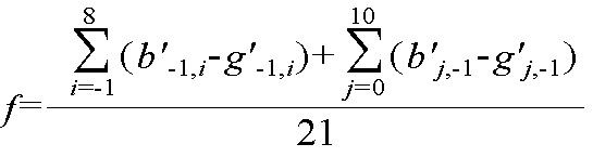
수학식 1에서 함수 f는 다양하게 정의될 수 있다. 일 실시예로서, G 색 성분 영상의 복원된 현재 화소 블록의 화소값(

Figure 112006048571522-pat00016
)과 이에 대응되는 B 색 성분 영상의 현재 화소 블록의 예측값(
Figure 112006048571522-pat00017
)을 다음의 수학식 2와 같이 1차 함수 관계로 정의할 수 있다. In Equation 1, the function f may be defined in various ways. In an embodiment, the pixel value of the restored current pixel block of the G color component image (
Figure 112006048571522-pat00016
) And the prediction value of the current pixel block of the corresponding B color component image (
Figure 112006048571522-pat00017
) Can be defined as a linear function relationship as in Equation 2 below.

Figure 112006048571522-pat00018

수학식 2에서 a는 G 색 성분 영상과 B 색 성분 사이의 상관 관계를 나타내는 소정의 가중치, b는 소정의 오프셋 값을 나타낸다. 수학식 2를 통해 얻어진 예측 화소값들은 영상의 각 화소값을 8비트로 표현하는 경우 0과 255 사이의 정수값으로 클리핑(clipping)된다. In Equation 2, a represents a predetermined weight indicating a correlation between the G color component image and the B color component, and b represents a predetermined offset value. The prediction pixel values obtained through Equation 2 are clipped to an integer value between 0 and 255 when each pixel value of the image is represented by 8 bits.

수학식 2의 a 및 b의 값은 화소의 위치 (i,j)에 따라서 변경될 수 있지만, 본 발명의 실시예에서는 소정의 블록 내에서 상수값을 갖는 경우를 고려한다. 일 예로, 상기 a 및 b의 값은 제 1 색 성분 영상의 주변 화소 블록의 복원된 화소값들을 이용하여 예측된 제 2 색 성분 영상의 주변 화소 블록의 예측 화소값들과 제 2 색 성분 영상의 주변 화소 블록의 복원된 화소값들 사이의 차이가 최소가 되도록 하는 값으로 결정된다. 즉, 제 1 색 성분 영상을 G 색 성분 영상이라고 하고, 나머지 색 성분 영상을 B 색 성분 영상이라고 할 때, 다음의 수학식 3과 같이. B 색 성분 영상의 주변 화소 블록 내의 복원된 화소값들(

Figure 112006048571522-pat00019
)과 상기 수학식 2를 통해 예측된 대응되는 B 색 성분 영상의 주변 화소 블록의 예측값들(
Figure 112006048571522-pat00020
)의 차이의 합이 최소화되는 값으로 결정될 수 있다.Although the values of a and b in Equation 2 may be changed according to the position (i, j) of the pixel, in the embodiment of the present invention, the case of having a constant value within a predetermined block is considered. For example, the values of a and b may correspond to predicted pixel values of the neighboring pixel block of the second color component image predicted by using reconstructed pixel values of the neighboring pixel block of the first color component image. The difference between the reconstructed pixel values of the neighboring pixel block is determined to be the minimum value. That is, when the first color component image is called a G color component image and the remaining color component images are called B color component images, as shown in Equation 3 below. Reconstructed pixel values in the neighboring pixel block of the B color component image
Figure 112006048571522-pat00019
And prediction values of neighboring pixel blocks of the corresponding B color component image predicted by Equation 2
Figure 112006048571522-pat00020
May be determined as a value that minimizes the sum of the differences.

Figure 112006048571522-pat00021

수학식 2에서 a 및 b를 결정하는 다른 방법으로 a의 값을 1로 결정하고, b는 다음의 수학식 4와 같이 B 색 성분 영상의 주변 화소 블록 내의 복원된 화소값들과 G 색 성분 영상의 복원된 주변 화소 블록의 화소값들의 차이의 평균으로 결정할 수 있다.As another method of determining a and b in Equation 2, the value of a is determined to be 1, and b is the reconstructed pixel values and the G color component image in the neighboring pixel block of the B color component image as shown in Equation 4 below. The average of the difference between the pixel values of the reconstructed neighboring pixel block may be determined.

Figure 112006048571522-pat00022

이와 같이 수학식 2의 상수 a 및 b의 값이 결정되면, 상관 예측부(314)는 복원된 G 색 성분 영상의 화소 블록의 각 화소값들(g'i,j)을 수학식 2에 대입하여 대응되는 B 색 성분 영상의 화소 블록의 화소값들을 예측한다.When the values of the constants a and b of Equation 2 are determined as described above, the correlation predicting unit 314 substitutes the respective pixel values g ' i, j of the pixel block of the reconstructed G color component image into Equation 2. The pixel values of the pixel block of the corresponding B color component image are predicted.

또 다른 a와 b의 값의 결정 방법으로는 통계 분야에서 많이 사용하는 선형 회귀(linear regression) 모델에 기반한 방법이 이용될 수 있다.Another method for determining the values of a and b may be a method based on a linear regression model, which is widely used in statistics.

도 8a는 본 발명에 따른 영상 부호화 방법 및 장치에서 8×8 화소 블록의 처리 순서를 나타낸 도면이고, 도 8b는 본 발명에 따른 영상 부호화 방법 및 장치에서 4×4 화소 블록의 처리 순서를 나타낸 도면이다.8A is a diagram illustrating a processing sequence of 8 × 8 pixel blocks in the image encoding method and apparatus according to the present invention, and FIG. 8B is a diagram illustrating a processing sequence of 4 × 4 pixel blocks in the video encoding method and apparatus according to the present invention. to be.

도 8a를 참조하면, B 색 성분 영상의 화소 블록을 8×8 모드로 처리하는 경우, 4개의 B 색 성분 영상의 8×8 화소 블록들은 좌에서 우, 위에서 아래 방향의 순서로 순차적으로 예측된다. B 색 성분 영상의 8×8 화소 블록의 처리는 블록 크기만 달라졌을 뿐, 전술한 B 색 성분 영상의 16×16 화소 블록의 화소값을 예측하는 과정과 유사하게 수학식 2를 통해 B 색 성분 영상의 8×8 화소 블록 내의 각 화소값들을 예측할 수 있다. 8×8 모드로 처리할 때, 수학식 2의 a 및 b는 B 색 성 분 영상의 복원된 주변 화소 블록의 화소값들과 대응되는 B 색 성분 영상의 주변 화소 블록의 예측값들의 차이의 합이 최소화되는 값으로 결정되거나, a는 1, b는 다음의 수학식 5와 같이 B 색 성분 영상의 8×8 주변 화소 블록 내의 복원된 화소값들과 G 색 성분 영상의 8×8 주변 화소 블록의 복원된 화소값들의 차이의 평균으로 결정할 수 있다.Referring to FIG. 8A, when a pixel block of a B color component image is processed in an 8 × 8 mode, 8 × 8 pixel blocks of four B color component images are sequentially predicted from left to right and top to bottom. . The processing of the 8x8 pixel block of the B color component image has only changed the block size, and similarly to the process of predicting the pixel value of the 16x16 pixel block of the B color component image, the B color component is represented by Equation 2 below. Each pixel value in an 8x8 pixel block of an image may be predicted. When processing in the 8x8 mode, a and b in Equation 2 are sums of differences of prediction values of neighboring pixel blocks of the B color component image corresponding to pixel values of the reconstructed neighboring pixel blocks of the B color component image. Or a is 1, and b is the value of the reconstructed pixel values in the 8 × 8 pixel block of the B color component image and the 8 × 8 pixel block of the G color component image as shown in Equation 5 below. The average of the difference between the reconstructed pixel values may be determined.

Figure 112006048571522-pat00023

도 8b를 참조하면, B 색 성분 영상의 화소 블록을 4×4 모드로 처리하는 경우, 16개의 B 색 성분 영상의 4×4 화소 블록들은 좌에서 우, 위에서 아래 방향의 순서로 순차적으로 예측된다. B 색 성분 영상의 각 4×4 화소 블록의 화소값들은 블록 크기만 달라졌을 뿐, 전술한 B 색 성분 영상의 16×16 화소 블록 또는 8×8 화소 블록의 화소값을 예측하는 과정과 유사하게 수학식 2를 통해 예측될 수 있다. Referring to FIG. 8B, when a pixel block of a B color component image is processed in a 4 × 4 mode, 4 × 4 pixel blocks of 16 B color component images are sequentially predicted from left to right and top to bottom. . The pixel values of each 4x4 pixel block of the B color component image are only different in block size, and similarly to the process of predicting pixel values of the 16x16 pixel block or 8x8 pixel block of the B color component image described above. It can be predicted through Equation 2.

수학식 2의 a 및 b는 B 색 성분 영상의 4×4 주변 화소 블록 내의 복원된 화소값들과 대응되는 B 색 성분 영상의 주변 화소 블록의 예측값들의 차이의 합이 최소화되는 값으로 결정되거나, a는 1로 고정되고 b는 다음의 수학식 6과 같이 B 색 성분 영상의 4×4 주변 화소 블록 내의 복원된 화소값들과 복원된 G 색 성분 영상의 4×4 주변 화소 블록의 화소값들의 차이의 평균으로 결정할 수 있다.(A) and (b) of Equation 2 are determined to be values that minimize the sum of the difference between the predicted values of the neighboring pixel blocks of the B color component image corresponding to the reconstructed pixel values in the 4x4 neighboring pixel block of the B color component image, or a is fixed to 1 and b is the value of the reconstructed pixel values in the 4x4 peripheral pixel block of the B color component image and the pixel values of the 4x4 peripheral pixel block of the reconstructed G color component image as shown in Equation 6 below. This can be determined by the average of the differences.

Figure 112006048571522-pat00024

전술한 바와 같이, 상관 예측은 각 매크로 블록(16×16)마다 16×16, 8×8, 4×4 블록 단위로 이루어질 수 있다. 한 적응적인 실시예로서, 상기 세 가지 블록 모드들 중 적합한 하나의 블록 단위로 각 매크로블록의 상관 예측이 이루어질 수 있다.As described above, correlation prediction may be performed in units of 16 × 16, 8 × 8, and 4 × 4 blocks for each macroblock 16 × 16. As an adaptive embodiment, correlation prediction of each macroblock may be performed in units of one suitable block among the three block modes.

감산부(307)는 B 색 성분 원영상의 화소 블록으로부터 상관 예측부(314)에서 복원된 G 색 성분 영상의 화소 블록의 화소값을 이용하여 예측된 예측 화소 블록의 차이를 계산하여 제 2 레지듀를 생성하고, 생성된 제 2 레지듀는 변환, 양자화 및 엔트로피 부호화 과정을 거쳐 비트스트림 형태로 출력된다.The subtractor 307 calculates the difference between the predicted pixel blocks predicted using the pixel values of the pixel blocks of the G color component image reconstructed by the correlation predictor 314 from the pixel blocks of the B color component original image, and then calculates the difference between the second blocks. The dew point is generated, and the generated second residue is transformed, quantized, and entropy encoded, and output in a bitstream form.

다음, R 색 성분 영상의 화소 블록의 화소값들은 전술한 B 색 성분 영상의 화소 블록의 화소값과 유사하게 복원된 G 색 성분 영상의 화소 블록의 화소값을 이용하여 예측될 수 있다.Next, the pixel values of the pixel block of the R color component image may be predicted using the pixel values of the pixel block of the G color component image reconstructed similarly to the pixel values of the pixel block of the B color component image.

한편, 상관 예측부(314)는 R 색 성분 영상의 화소 블록의 화소값을 예측할 때, 복원된 G 색 성분 영상의 화소 블록 대신에 이전에 처리된 B 색 성분 영상의 화소 블록의 복원된 화소값을 이용하여 예측될 수 있다. 즉, B 색 성분 원영상의 화소 블록으로부터 B 색 성분 영상의 예측 화소 블록의 차이인 제 2 레지듀를 변환 및 양자화한 값을 다시 역변환 및 역양자화하고, 역변환 및 역양자화된 제 2 레지 듀와 B 색 성분 영상의 예측 화소 블록을 더함으로써 복원된 B 색 성분의 화소 블록을 R 색 성분 영상의 화소 블록의 예측에 이용할 수 있다. Meanwhile, when the correlation predicting unit 314 predicts the pixel value of the pixel block of the R color component image, the restored pixel value of the pixel block of the B color component image previously processed instead of the pixel block of the reconstructed G color component image. Can be predicted using. That is, the inverse transform and inverse quantization of the second residue transformed from the pixel block of the B color component original image and the difference between the predicted pixel blocks of the B color component image and the inverse transform and inverse quantization are performed. By adding the prediction pixel blocks of the B color component image, the reconstructed pixel blocks of the B color component can be used to predict the pixel blocks of the R color component image.

구체적으로, 복원된 B 색 성분 영상의 화소 블록의 i번째 행, j번째 열에 위치한 화소값을

Figure 112006048571522-pat00025
, 상기
Figure 112006048571522-pat00026
에 대응되는 R 색 성분 영상의 화소 블록의 i번째 행, j번째 열에 위치한 화소의 예측값을
Figure 112006048571522-pat00027
, c는 B 색 성분 영상과 R 색 성분 사이의 상관 관계를 나타내는 소정의 가중치, d는 소정의 오프셋 값이라 할 때, 상관 예측부(314)는 B 색 성분 영상과 R 색 성분 영상 사이의 상관 관계를 다음의 수학식 7과 같이 1차 함수로 모델링하여, B 색 성분 영상의 화소값에 대응되는 R 색 성분 영상의 화소값을 예측할 수 있다.Specifically, the pixel values located in the i th row and the j th column of the pixel block of the restored B color component image are determined.
Figure 112006048571522-pat00025
, remind
Figure 112006048571522-pat00026
Predicted values of pixels located in the i th row and the j th column of the pixel block of the R color component image corresponding to
Figure 112006048571522-pat00027
, c is a predetermined weight indicating a correlation between the B color component image and the R color component, and d is a predetermined offset value, the correlation predicting unit 314 determines that the correlation between the B color component image and the R color component image The relationship may be modeled using a linear function as shown in Equation 7 to predict the pixel value of the R color component image corresponding to the pixel value of the B color component image.

Figure 112006048571522-pat00028

전술한 바와 같이, 수학식 7을 통해 얻어진 예측 화소값들은 영상의 각 화소값을 8비트로 표현하는 경우 0과 255 사이의 정수값으로 클리핑(clipping)된다. 상기 c 및 d의 값은 전술한 a 및 b의 값의 결정 과정과 유사하게, B 색 성분 영상의 복원된 주변 화소 블록의 화소값들 및 R 색 성분 영상의 복원된 주변 화소 블록의 화소값을 이용하여 결정될 수 있다.As described above, the prediction pixel values obtained through Equation 7 are clipped to an integer value between 0 and 255 when each pixel value of the image is represented by 8 bits. The values of c and d correspond to pixel values of the reconstructed peripheral pixel block of the B color component image and pixel values of the reconstructed peripheral pixel block of the R color component image, similarly to the above-described determination of the values of a and b. Can be determined using.

수학식 7의 상수 c 및 d의 값이 결정되면, 상관 예측부(314)는 복원된 B 색 성분 영상의 화소 블록의 각 화소값들(b'i,j)을 수학식 6에 대입하여 대응되는 R 색 성분 영상의 화소 블록의 화소값들을 예측한다.When the values of the constants c and d of Equation 7 are determined, the correlation predicting unit 314 substitutes the respective pixel values b ' i, j of the pixel block of the reconstructed B color component image into Equation 6 to correspond. The pixel values of the pixel block of the R color component image are predicted.

수학식 2 및 수학식 7의 a 및 b, c 및 d의 값은 생성된 비트스트림의 헤더에 예측 모드 정보로서 삽입되어 복호화단에 전송됨으로써 복호화단에서 복호화를 수행할 수 있도록 하는 것이 바람직하다. 그러나, 복호기에서도 부호기와 동일한 방법으로 각 색 성분의 복원된 주변 화소들을 이용하여 a 및 b, c 및 d의 값을 생성할 수 있기 때문에, a 및 b, c 및 d의 값을 별도로 비트스트림에 포함하지 않고, 복호기에 생성하여 사용하는 것도 가능하다.The values of a, b, c, and d in Equations 2 and 7 are preferably inserted into the header of the generated bitstream as prediction mode information and transmitted to the decoder so that the decoder can perform decoding. However, since the decoder can generate the values of a and b, c and d using the reconstructed neighboring pixels of each color component in the same way as the encoder, the values of a and b, c and d are separately added to the bitstream. It is also possible to generate and use the decoder without including it.

도 9는 본 발명의 다른 실시예에 따른 영상 부호화 장치의 구성을 나타낸 블록도이고, 도 10은 본 발명의 다른 실시예에 따른 영상 부호화 방법을 나타낸 플로우 차트이다.9 is a block diagram illustrating a configuration of an image encoding apparatus according to another embodiment of the present invention, and FIG. 10 is a flowchart illustrating an image encoding method according to another embodiment of the present invention.

본 발명의 다른 실시예에 따른 영상 부호화 장치(900)는 전술한 본 발명의 일 실시예에 따른 도 3의 영상 부호화 장치(300)과 그 구성 및 동작에 있어서 유사하나, 복원된 제 1 색 성분 영상에서 에지를 검출하는 에지 검출부(901) 및 영역 분리부(902)를 더 포함하고 있다. 이하에서는 전술한 본 발명의 일 실시예에 따른 영상 부호화 장치와 동일한 구성 요소에 대한 구체적인 설명은 생략하고, 본 발명의 일 실시예에 따른 영상 부호화 장치와 차이가 나는 부분을 중심으로 본 발명의 다른 실시예에 따른 영상 부호화 장치 및 방법에 대하여 설명한다.The image encoding apparatus 900 according to another embodiment of the present invention is similar in structure and operation to the image encoding apparatus 300 of FIG. 3 according to an embodiment of the present invention, but reconstructed a first color component. The apparatus further includes an edge detector 901 and an area separator 902 for detecting edges in an image. Hereinafter, a detailed description of the same components as the image encoding apparatus according to an embodiment of the present invention described above will be omitted, and other parts of the present invention will be mainly focused on portions that differ from the image encoding apparatus according to the embodiment of the present invention. A video encoding apparatus and a method according to an embodiment will be described.

단계 1010에서, 움직임 추정부(903) 및 움직임 보상부(904)에 의한 움직임 예측 보상 또는 인트라 예측부(905)에 의한 인트라 예측을 통해 G 색 성분 영상의 화소 블록에 대한 예측 화소 블록을 생성한다. G 색 성분 영상의 예측 화소 블록 과 G 색 성분 원영상의 화소 블록의 차이인 제 1 레지듀는 변환, 양자화 및 엔트로피 부호화 과정을 통해 부호화되어 비트스트림으로 출력된다.In operation 1010, the prediction pixel block of the pixel block of the G color component image is generated through motion prediction compensation by the motion estimator 903 and the motion compensator 904 or intra prediction by the intra predictor 905. . The first residue, which is the difference between the predicted pixel block of the G color component image and the pixel block of the G color component original image, is encoded through a transform, quantization, and entropy encoding process and output as a bitstream.

단계 1020에서, 변환 및 양자화된 제 1 레지듀에 대해 역변환 및 역양자화 과정을 수행하여 제 1 레지듀를 복원한 다음, G 색 성분 영상의 예측 화소 블록과 제 1 레지듀를 더하여 G 색 성분 영상의 화소 블록을 복원한다.In operation 1020, the first residual is reconstructed by performing an inverse transform and inverse quantization process on the transformed and quantized first residue, and then the prediction pixel block and the first residue of the G color component image are added to the G color component image. Restore the pixel block.

단계 1030에서, 에지 검출부(901)는 복원된 제 1 색 성분 영상의 소정 크기의 화소 블록 내에 존재하는 에지를 검출한다. 화소 블록 내에 존재하는 에지를 검출하는 이유는, 화소 블록 내에 에지가 존재하는 경우 에지를 중심으로 나누어진 화소 블록 내의 영역 사이에도 컬러 특성이 변화될 수 있기 때문이다. 따라서, 본 발명의 다른 실시예에 따른 영상 부호화 방법 및 장치는 화소 블록 내에 존재하는 에지를 검출하고, 검출된 에지를 중심으로 화소 블록을 분리한 다음, 분리된 영역 별로 전술한 본 발명의 일 실시예와 유사하게 복원된 제 1 색 성분 영상의 화소값으로부터 다른 나머지 색 성분 영상의 화소값을 예측한다.In operation 1030, the edge detector 901 detects an edge existing in a pixel block of a predetermined size of the reconstructed first color component image. The reason for detecting an edge existing in the pixel block is that color characteristics may change even between regions in the pixel block divided about the edge when an edge exists in the pixel block. Accordingly, an image encoding method and apparatus according to another embodiment of the present invention detect an edge existing in a pixel block, separate a pixel block based on the detected edge, and then perform the aforementioned embodiments of the present invention for each separated region. Similarly to the example, the pixel value of the other remaining color component image is predicted from the pixel value of the reconstructed first color component image.

에지 검출 방법으로는 소벨 연산자(sobel operator), 캐니 에지 검출 알고리즘(canny edge detection) 등 다양한 에지 검출 알고리즘이 적용될 수 있다. 또한, 에지 검출부(901)를 구비하지 않고, 인트라 예측부(905)에서 결정된 인트라 예측 모드의 방향을 에지 방향으로 판단할 수도 있다.As an edge detection method, various edge detection algorithms such as a sobel operator and a canny edge detection algorithm may be applied. In addition, the direction of the intra prediction mode determined by the intra predictor 905 may be determined as the edge direction without the edge detector 901.

단계 1040에서, 영역 분리부(902)는 검출된 에지를 이용하여 제 1 색 성분 영상의 화소 블록 및 대응되는 나머지 색 성분 영상의 화소 블록을 분리한다.In operation 1040, the region separator 902 separates the pixel block of the first color component image and the pixel block of the corresponding remaining color component image by using the detected edge.

도 11a는 검출된 에지를 이용하여 G 색 성분 영상의 화소 블록을 분리하는 일 예를 나타낸 도면이고, 도 11b는 검출된 에지를 이용하여 B 색 성분 영상의 화소 블록을 분리하는 일 예를 나타낸 도면이며, 도 11c는 검출된 에지를 이용하여 R 색 성분 영상의 화소 블록을 분리하는 일 예를 나타낸 도면이다. 도 11a 내지 11c를 참조하면, 에지 검출부(901)에서 복원된 G 색 성분 영상의 화소 블록 내에 하나의 에지가 존재하는 것으로 판단되면, 영역 분리부(902)는 B 색 성분 영상의 화소 블록 및 R 색 성분 영상의 화소 블록에도 동일한 에지가 존재하는 것으로 판단하고, 검출된 에지를 이용하여 각 색 성분의 화소 블록을 2개의 영역(I,II)으로 분리한다.11A is a diagram illustrating an example of separating pixel blocks of a G color component image using detected edges, and FIG. 11B is a diagram illustrating an example of separating pixel blocks of a B color component image using detected edges. 11C is a diagram illustrating an example of separating pixel blocks of an R color component image by using detected edges. 11A to 11C, if it is determined that one edge exists in the pixel block of the reconstructed G color component image by the edge detector 901, the area separator 902 may determine the pixel block and R of the B color component image. It is determined that the same edge exists in the pixel block of the color component image, and the pixel block of each color component is divided into two regions I and II using the detected edge.

단계 1050에서, 상관 예측부(913)는 복원된 G 색 성분 영상의 화소 블록을 이용하여 분리된 각 영역별로 대응되는 나머지 B 색 성분 영상 및 R 색 성분 영상의 화소 블록의 화소값을 예측한다. 즉, 상관 예측부(913)는 제 1 영역(I)에 존재하는 복원된 G 색 성분 영상의 화소값들(g'i,j)를 이용하여, 제 1 영역(I)에 대응되는 B 색 성분 영상의 화소 블록 내의 화소값 및 R 색 성분 영상의 화소 블록 내의 화소값을 예측한다. 유사하게, 상관 예측부(913)는 제 2 영역(II)에 존재하는 복원된 G 색 성분 영상의 화소값들(g'i,j)를 이용하여, 제 2 영역(II)에 대응되는 B 색 성분 영상의 화소 블록 내의 화소값 및 R 색 성분 영상의 화소 블록 내의 화소값을 예측한다.In operation 1050, the correlation predictor 913 predicts pixel values of the pixel blocks of the remaining B color component image and the R color component image corresponding to each of the divided regions using the pixel block of the reconstructed G color component image. That is, the correlation predictor 913 uses the pixel values g ' i, j of the reconstructed G color component image existing in the first region I, and the B color corresponding to the first region I. Pixel values in the pixel block of the component image and pixel values in the pixel block of the R color component image are predicted. Similarly, the correlation predictor 913 uses B corresponding to the second region II by using pixel values g'i, j of the reconstructed G color component image existing in the second region II. Pixel values in the pixel block of the color component image and pixel values in the pixel block of the R color component image are predicted.

구체적으로, 각 색 성분 영상의 화소 블록이 n개의 영역으로 분리되고, 복원된 G 색 성분 영상의 화소 블록의 k번째 영역(k=1,2,...,n) 내의 임의의 화소값을

Figure 112006048571522-pat00029
, 상기
Figure 112006048571522-pat00030
에 대응되는 B 색 성분 영상의 화소 블록의 k번째 영역의 화소의 예측값을
Figure 112006048571522-pat00031
, e는 상기 G 색 성분 영상의 k번째 영역과 B 색 성분 영상의 k번째 영역 사이의 상관 관계를 나타내는 소정의 가중치, f는 소정의 오프셋 값이라 하면, 상기 B 색 성분 영상의 화소 블록의 화소값들은 전술한 수학식 2와 유사하게 다음의 수학식 8을 통해 예측될 수 있다.Specifically, the pixel block of each color component image is divided into n regions, and any pixel value in the k-th region (k = 1, 2, ..., n) of the pixel block of the reconstructed G color component image is divided.
Figure 112006048571522-pat00029
, remind
Figure 112006048571522-pat00030
Predicts a pixel of a k-th region of a pixel block of a B-color component image corresponding to
Figure 112006048571522-pat00031
e is a predetermined weight representing a correlation between a k-th region of the G color component image and a k-th region of the B color component image, and f is a pixel of the pixel block of the B color component image. The values can be predicted through the following Equation 8 similarly to Equation 2 described above.

Figure 112006048571522-pat00032

수학식 8에서 상수 e 및 f는 제 1 색 성분 영상의 주변 화소 블록의 복원된 화소값들을 이용하여 예측된 제 2 색 성분 영상의 화소 블록의 k번째 영역에 인접한 제 2 색 성분 영상의 주변 화소 블록의 예측 화소값들과, 제 2 색 성분 영상의 화소 블록의 k번째 영역에 인접한 제 2 색 성분 영상의 주변 화소 블록의 복원된 화소값들 사이의 차이가 최소가 되도록 하는 값으로 결정될 수 있다. In Equation 8, constants e and f are peripheral pixels of the second color component image adjacent to the k-th region of the pixel block of the second color component image predicted using the reconstructed pixel values of the peripheral pixel block of the first color component image. The difference between the predicted pixel values of the block and the reconstructed pixel values of the neighboring pixel block of the second color component image adjacent to the k-th region of the pixel block of the second color component image may be determined to be the minimum value. .

간단한 예로서, e는 1이고, f는 제 2 색 성분 영상의 화소 블록의 k번째 영역에 인접한 제 2 색 성분 영상의 주변 화소 블록의 복원된 화소값들과 제 2 색 성분 영상의 화소 블록의 k번째 영역에 인접한 제 1 색 성분 영상의 주변 화소 블록의 복원된 화소값들 사이의 차이의 평균을 이용하여 결정될 수 있다. 도 11a 및 도 11b를 참조하면, 제 1 색 성분 영상을 G 색 성분 영상, 제 2 색 성분 영상을 B 색 성분 영상이라고 할 때, 1번째 영역(I)에 적용할 수학식 9의 f는 현재 화소 블 록의 1번째 영역(I)에 인접한 G 색 성분 영상의 주변 화소 블록의 화소들(1110)의 복원된 화소값 및 이에 대응되는 B 색 성분 영상의 주변 화소 블록의 화소들(1112)의 복원된 화소값을 이용하여 다음의 수학식 9와 같이 정의될 수 있다.As a simple example, e is 1 and f is the reconstructed pixel values of the peripheral pixel block of the second color component image adjacent to the kth region of the pixel block of the second color component image and the pixel block of the second color component image. The average of the difference between the reconstructed pixel values of the neighboring pixel blocks of the first color component image adjacent to the k-th region may be determined. 11A and 11B, when the first color component image is referred to as the G color component image and the second color component image is referred to as the B color component image, f in Equation 9 to be applied to the first region I is The reconstructed pixel values of the pixels 1110 of the peripheral pixel block of the G color component image adjacent to the first region I of the pixel block and the pixels 1112 of the peripheral pixel block of the B color component image corresponding thereto. Using the reconstructed pixel value, it may be defined as in Equation 9 below.

Figure 112006048571522-pat00033

유사하게, 2번째 영역(II)에 적용할 수학식 8의 f는 현재 화소 블록의 2번째 영역(II)에 인접한 G 색 성분 영상의 주변 화소 블록의 화소들(1120,1130)의 복원된 화소값 및 이에 대응되는 B 색 성분 영상의 주변 화소 블록의 화소들(1122,1132)의 복원된 화소값을 이용하여 다음의 수학식 10과 같이 정의될 수 있다.Similarly, f in Equation 8 to be applied to the second region II is a reconstructed pixel of the pixels 1120 and 1130 of the neighboring pixel block of the G color component image adjacent to the second region II of the current pixel block. A value and a restored pixel value of the pixels 1122 and 1132 of the neighboring pixel block of the B color component image may be defined as shown in Equation 10 below.

Figure 112006048571522-pat00034

전술한 각 영역별 B 색 성분 영상의 화소 블록의 화소값을 각 영역별로 예측하는 것과 유사하게 R 색 성분 영상의 화소 블록의 화소값을 각 영역별로 예측할 수 있다.Similar to predicting the pixel value of the pixel block of the B color component image for each region, the pixel value of the pixel block of the R color component image may be predicted for each region.

한편, R 색 성분 영상의 화소 블록의 화소값을 예측할 때 복원된 G 색 성분 영상의 화소 블록의 화소값을 이용하는 대신에 전술한 수학식 7과 유사하게 동일 영역 내에 존재하는 복원된 B 색 성분 영상의 화소 블록의 화소값을 이용하여 R 색 성분 영상의 화소 블록의 화소값들을 예측할 수 있다.Meanwhile, instead of using the pixel value of the pixel block of the reconstructed G color component image when predicting the pixel value of the pixel block of the R color component image, the reconstructed B color component image existing within the same region similarly to Equation 7 described above. The pixel values of the pixel block of the R color component image may be predicted using the pixel values of the pixel block of.

도 12는 본 발명의 바람직한 실시예에 따른 영상 복호화 장치의 구성을 나타낸 도면이다.12 is a diagram illustrating a configuration of an image decoding apparatus according to a preferred embodiment of the present invention.

도 12를 참조하면, 본 발명에 따른 영상 복호화 장치(1200)는 엔트로피 디코더(1210), 재정렬부(1220), 역양자화부(1230), 역변환부(1240), 인트라 예측부(1250), 움직임 보상부(1260), 상관 예측부(1270) 및 필터(1280)를 구비한다. Referring to FIG. 12, the image decoding apparatus 1200 according to the present invention includes an entropy decoder 1210, a reordering unit 1220, an inverse quantization unit 1230, an inverse transform unit 1240, an intra predictor 1250, and a motion. The compensator 1260, the correlation predictor 1270, and the filter 1280 are provided.

상기 엔트로피 디코더(1210) 및 재정렬부(1220)는 압축된 비트스트림을 수신하여 엔트로피 복호화를 수행하여 양자화된 계수를 생성한다. 상기 역양자화부(1230) 및 역변환부(1240)는 양자화된 계수에 대한 역양자화 및 역변환을 수행하여 각 색 성분 영상의 레지듀 정보, 움직임 벡터 정보 및 예측 모드 정보 등을 추출한다. 여기서, 예측 모드 정보에는 본 발명에 따라 부호화된 비트스트림인지 여부를 나타내는 소정의 신택스가 포함될 수 있다. 또한, 본 발명에 따른 영상 부호화 방법에 따라 부호화된 비트스트림인 경우 상기 예측 모드 정보에는 나머지 색 성분 영상의 화소 블록의 화소값을 예측하는 데 이용되는 예측자 정보, 즉 전술한 수학식 2의 a 및 b, 수학식 7의 c 및 d, 수학식 8의 e 및 f 값 정보가 포함될 수 있다. The entropy decoder 1210 and the reordering unit 1220 receive the compressed bitstream and perform entropy decoding to generate quantized coefficients. The inverse quantizer 1230 and the inverse transformer 1240 perform inverse quantization and inverse transformation on quantized coefficients to extract residue information, motion vector information, and prediction mode information of each color component image. Here, the prediction mode information may include a predetermined syntax indicating whether or not the bitstream is encoded according to the present invention. In the case of the bitstream encoded according to the image encoding method according to the present invention, the prediction mode information includes predictor information used to predict pixel values of the pixel blocks of the remaining color component images, that is, the a And b, c and d of Equation 7, and e and f value information of Equation 8 may be included.

움직임 보상부(1260)은 현재 화소 블록이 인터 예측된 화소 블록인 경우 움직임 보상 및 예측을 통해 예측 화소 블록을 생성한다. 인트라 예측부(1250)는 현 재 화소 블록이 인트라 예측된 화소 블록인 경우 인트라 예측을 수행하여 예측 화소 블록을 생성한다.The motion compensator 1260 generates a predicted pixel block through motion compensation and prediction when the current pixel block is an inter predicted pixel block. The intra predictor 1250 generates an prediction pixel block by performing intra prediction when the current pixel block is an intra predicted pixel block.

가산부(1275)는 제 1 색 성분 영상의 예측 화소 블록과 역변환부(1240)에서 출력되는 제 1 레지듀를 합산하여 제 1 색 성분 영상의 화소 블록을 복호화한다.The adder 1275 decodes the pixel block of the first color component image by summing the prediction pixel block of the first color component image and the first residue output from the inverse transform unit 1240.

복호화된 제 1 색 성분 영상의 화소 블록은 다시 상관 예측부(1270)로 입력된다. 상관 예측부(1270)는 복호화된 제 1 색 성분 영상의 화소 블록을 이용하여 대응되는 나머지 색 성분 영상의 화소 블록을 복호화한다.The pixel block of the decoded first color component image is input to the correlation predictor 1270 again. The correlation predictor 1270 decodes the pixel block of the corresponding remaining color component image by using the decoded pixel block of the first color component image.

구체적으로, 전술한 본 발명에 따른 도 3의 상관 예측부(314)와 동일하게 상관 예측부(1270)는 복호화된 제 1 색 성분 영상의 화소 블록의 화소값을 수학식 2에 대입하여 제 2 또는 제 3 색 성분 영상의 화소 블록의 화소값을 예측할 수 있다. 만약 제 3 색 성분 영상이 복원된 제 2 색 성분 영상을 이용하여 예측된 경우에는 전술한 수학식 7과 같이 복원된 제 2 색 성분 영상의 화소 블록의 화소값들을 이용하여 제 3 색 성분 영상의 화소 블록의 화소값을 예측할 수 있다.Specifically, similarly to the correlation predicting unit 314 of FIG. 3 according to the present invention, the correlation predicting unit 1270 substitutes the pixel value of the pixel block of the decoded first color component image into Equation 2 to generate a second value. Alternatively, the pixel value of the pixel block of the third color component image may be predicted. If the third color component image is predicted using the reconstructed second color component image, the pixel value of the pixel block of the reconstructed second color component image of the third color component image, as shown in Equation 7, is used. The pixel value of the pixel block can be predicted.

상관 예측부(1270)에서 예측된 제 2 및 제 3 색 성분 영상의 예측 화소 블록들 각각은 역변환부(1240)에서 출력되는 제 2 레지듀 및 제 3 레지듀 성분과 합산됨으로써 제 2 및 제 3 색 성분 영상의 화소 블록이 복호화된다.Each of the prediction pixel blocks of the second and third color component images predicted by the correlation predictor 1270 is summed with the second and third residue components output from the inverse transform unit 1240, so that the second and third predicted pixel blocks are combined. The pixel block of the color component image is decoded.

한편, 전술한 본 발명의 다른 실시예에 따라 화소 블록 내에 존재하는 에지를 검출하여 각 영역별로 부호화된 비트스트림을 부호화하는 경우에는, 수신된 복수 개의 색 성분들의 부호화된 영상들을 구비하는 비트스트림에서 제 1 색 성분 영상의 화소 블록 내에 존재하는 에지를 검출하는 에지 검출부(미도시) 및 검출된 에 지를 이용하여 각 색 성분 영상의 화소 블록을 분리하는 영역 분리부(미도시)를 더 포함할 수 있다. 이 경우, 도 9의 상관 예측부(913)과 동일하게 상관 예측부(1270)는 복호화된 G 색 성분 영상의 화소 블록을 이용하여 분리된 각 영역별로 대응되는 나머지 B 색 성분 영상 및 R 색 성분 영상의 화소 블록의 화소값을 예측한다. 또한, 전술한 바와 같이 나머지 색 성분 영상의 화소값을 예측하는데 이용되는 예측자의 상수값은 주변 화소 블록의 복원된 화소값을 이용하여 결정되거나, 비트스트림에 구비된 예측 모드 정보를 이용하여 결정될 수 있다.Meanwhile, according to another embodiment of the present invention, in the case where an edge existing in a pixel block is detected and an encoded bitstream is encoded for each region, the bitstream including encoded images of a plurality of received color components may be used. The apparatus may further include an edge detector (not shown) for detecting edges existing in the pixel block of the first color component image, and a region separator (not shown) for separating the pixel blocks of each color component image using the detected edges. have. In this case, similarly to the correlation predictor 913 of FIG. 9, the correlation predictor 1270 uses the remaining B color component image and the R color component corresponding to each region separated using the pixel block of the decoded G color component image. The pixel value of the pixel block of the image is predicted. In addition, as described above, the constant value of the predictor used to predict the pixel value of the remaining color component image may be determined using the reconstructed pixel value of the neighboring pixel block or may be determined using the prediction mode information included in the bitstream. have.

도 13은 본 발명의 일 실시예에 따른 영상 복호화 방법을 나타낸 플로우 차트이다.13 is a flowchart illustrating an image decoding method according to an embodiment of the present invention.

도 13을 참조하면, 단계 1310에서 적어도 두 가지 색 성분들의 부호화된 영상들을 구비하는 비트스트림을 수신한다.Referring to FIG. 13, in operation 1310, a bitstream including encoded images of at least two color components is received.

단계 1320에서, 비트스트림에 구비된 복수 개의 색 성분들의 영상들 중에서 제 1 색 성분 영상의 소정 크기의 화소 블록에 대한 예측 화소 블록을 생성하고, 단계 1330에서, 제 1 색 성분 영상의 예측 화소 블록을 제 1 레지듀와 더하여 제 1 색 성분 영상의 화소 블록을 복호화한다.In operation 1320, a prediction pixel block of a pixel block having a predetermined size of the first color component image is generated among the plurality of image components of the color stream. In operation 1330, the prediction pixel block of the first color component image is generated. Is added to the first residue to decode the pixel block of the first color component image.

단계 1340에서, 복호화된 제 1 색 성분 영상의 화소 블록과 제 1 색 성분 영상의 복호화된 주변 화소 블록 및 현재 복호화하고자 하는 나머지 색 성분 영상의 복호화된 주변 화소 블록을 이용하여 나머지 색 성분 영상의 화소 블록의 화소값을 예측함으로써 나머지 색 성분 영상의 화소 블록의 예측 화소 블록을 생성한다. 전술한 바와 같이, 나머지 색 성분 영상의 화소 블록의 예측에 이용되는 수학식 2 또 는 수학식 7과 같은 예측자를 형성하기 위해서 비트스트림에 구비된 예측 모드 정보를 이용하거나, 제 1 색 성분 영상의 복호화된 주변 화소 블록 및 현재 복호화하고자 하는 나머지 색 성분 영상의 복호화된 주변 화소 블록을 이용한다. 다음 상관 예측부(1270)는 복호화된 제 1 색 성분 영상의 화소 블록의 화소값을 이용하여 나머지 제 2 및 제 3 색 성분 영상의 화소 블록의 화소값들을 예측하거나, 복호화된 제 2 색 성분 영상을 이용하여 제 3 색 성분 영상의 화소 블록의 화소값들을 예측한다.In operation 1340, the pixel of the remaining color component image is obtained by using the decoded pixel block of the first color component image, the decoded neighbor pixel block of the first color component image, and the decoded neighbor pixel block of the remaining color component image to be decoded. The predicted pixel block of the pixel block of the remaining color component image is generated by predicting the pixel value of the block. As described above, the prediction mode information included in the bitstream is used to form a predictor such as Equation 2 or Equation 7 used to predict the pixel blocks of the remaining color component images, or the first color component image may be used. The decoded neighboring pixel block and the decoded neighboring pixel block of the remaining color component image to be decoded are used. The correlation predictor 1270 predicts pixel values of the pixel blocks of the second and third color component images using the pixel values of the pixel block of the decoded first color component image, or decodes the second color component image. The pixel values of the pixel block of the third color component image are predicted by using.

단계 1350에서, 제 2 및 제 3 색 성분 영상의 화소 블록의 예측 화소 블록 각각을 역변환된 제 2 레지듀 및 제 3 레지듀 성분과 합산하여 제 2 및 제 3 색 성분 영상의 화소 블록을 복호화한다.In operation 1350, the pixel blocks of the second and third color component images are decoded by adding the predicted pixel blocks of the pixel blocks of the second and third color component images with the inverse transformed second and third residue components. .

도 14는 본 발명의 다른 실시예에 따른 영상 복호화 방법을 나타낸 플로우 차트이다. 본 발명의 다른 실시예에 따른 영상 복호화 방법은 각 색 성분 영상의 화소 블록 내에 존재하는 에지를 중심으로 각 영역별로 분리되어 부호화된 색 성분 영상의 화소 블록을 복원하는 것을 제외하고는 전술한 본 발명의 일 실시예에 따른 영상 복호화 방법과 유사하다.14 is a flowchart illustrating an image decoding method according to another embodiment of the present invention. The image decoding method according to another embodiment of the present invention is the above-described embodiment of the present invention except that the pixel block of the color component image, which is separated and encoded for each region based on an edge existing in the pixel block of each color component image, is restored. It is similar to the image decoding method according to an embodiment of.

도 14를 참조하면, 단계 1410에서 적어도 두 가지 색 성분들의 부호화된 영상들을 구비하는 비트스트림을 수신한다.Referring to FIG. 14, in operation 1410, a bitstream including encoded images of at least two color components is received.

단계 1420에서, 복수 개의 색 성분들의 영상들 중에서 제 1 색 성분 영상의 소정 크기의 화소 블록을 복호화한다.In operation 1420, a pixel block of a predetermined size of the first color component image is decoded among the images of the plurality of color components.

단계 1430에서, 복호화된 제 1 색 성분 영상의 화소 블록 내에 존재하는 에 지를 검출한다.In operation 1430, an edge existing in the pixel block of the decoded first color component image is detected.

단계 1440에서, 검출된 에지를 이용하여 복호화된 제 1 색 성분 영상의 화소 블록 및 대응되는 나머지 색 성분 영상의 화소 블록을 분리한다.In operation 1440, the pixel block of the decoded first color component image and the pixel block of the corresponding remaining color component image are separated using the detected edge.

단계 1450에서, 복호화된 제 1 색 성분 영상의 화소 블록을 이용하여 분리된 각 영역별로 제 2 및 제 3 색 성분 영상의 화소 블록의 화소값을 예측한다.In operation 1450, the pixel values of the pixel blocks of the second and third color component images are predicted for each of the separated regions using the pixel blocks of the decoded first color component image.

각 영역별로 예측된 제 2 및 제 3 색 성분 영상의 화소값은 결합되어 제 2 및 제 3 색 성분 영상의 예측 화소 블록이 형성되며, 제 2 및 제 3 색 성분의 예측 화소 블록은 역변환된 제 2 레지듀 및 제 3 레지듀 성분과 합산되어 제 2 및 제 3 색 성분 영상의 화소 블록이 복호화된다.Pixel values of the second and third color component images predicted for each region are combined to form prediction pixel blocks of the second and third color component images, and the predicted pixel blocks of the second and third color component images are inversely transformed. The pixel blocks of the second and third color component images are decoded by adding up the second and third residue components.

본 발명은 또한 컴퓨터로 읽을 수 있는 기록매체에 컴퓨터가 읽을 수 있는 코드로서 구현하는 것이 가능하다. 컴퓨터가 읽을 수 있는 기록매체는 컴퓨터 시스템에 의하여 읽혀질 수 있는 데이터가 저장되는 모든 종류의 기록장치를 포함한다. 컴퓨터가 읽을 수 있는 기록매체의 예로는 ROM, RAM, CD-ROM, 자기 테이프, 플로피디스크, 광 데이터 저장장치 등이 있으며, 또한 캐리어 웨이브(예를 들어 인터넷을 통한 전송)의 형태로 구현되는 것도 포함한다. 또한 컴퓨터가 읽을 수 있는 기록매체는 네트워크로 연결된 컴퓨터 시스템에 분산되어, 분산방식으로 컴퓨터가 읽을 수 있는 코드가 저장되고 실행될 수 있다.The present invention can also be embodied as computer-readable codes on a computer-readable recording medium. A computer-readable recording medium includes all kinds of recording apparatuses in which data that can be read by a computer system is stored. Examples of the computer-readable recording medium include a ROM, a RAM, a CD-ROM, a magnetic tape, a floppy disk, an optical data storage device, and the like, and may be implemented in the form of a carrier wave (for example, transmission via the Internet) . The computer readable recording medium may also be distributed over a networked computer system so that computer readable code can be stored and executed in a distributed manner.

이제까지 본 발명에 대하여 그 바람직한 실시예들을 중심으로 살펴보았다. 본 발명이 속하는 기술 분야에서 통상의 지식을 가진 자는 본 발명의 본질적인 특성에서 벗어나지 않는 범위에서 변형된 형태로 구현될 수 있음을 이해할 수 있을 것이다. 그러므로 개시된 실시예들은 한정적인 관점이 아니라 설명적인 관점에서 고려되어야 한다. 본 발명의 범위는 전술한 설명이 아니라 특허청구범위에 나타나 있으며, 그와 동등한 범위 내에 있는 모든 차이점은 본 발명에 포함된 것으로 해석되어야 할 것이다. So far I looked at the center of the preferred embodiment for the present invention. Those skilled in the art will understand that the present invention may be implemented in a modified form without departing from the essential characteristics of the present invention. Therefore, the disclosed embodiments should be considered in an illustrative rather than a restrictive sense. The scope of the present invention is defined by the appended claims rather than by the foregoing description, and all differences within the scope of equivalents thereof should be construed as being included in the present invention.

전술한 본 발명에 따르면, 하나의 영상을 구성하는 복수 개의 색 성분 영상들 사이의 상관 관계를 이용하여 예측 부호화를 수행함으로써 영상의 부호화 효율을 향상시킬 수 있다.According to the present invention described above, the encoding efficiency of an image can be improved by performing predictive encoding by using a correlation between a plurality of color component images forming one image.

또한, 본 발명에 따르면, RGB 입력 영상을 YUV 도메인으로 변환하지 않고 입력 영상 그대로 RGB 도메인에서 부호화를 수행함으로써, RGB 입력 영상을 다른 컬러 포맷으로 변환하는 과정 중에 발생하는 색상의 왜곡 등을 방지하여 영상의 품질을 향상시킬 수 있다.In addition, according to the present invention, by encoding in the RGB domain as it is without converting the RGB input image to the YUV domain, by preventing the distortion of the color generated during the process of converting the RGB input image to another color format, the image Can improve the quality.

Claims (44)

영상의 부호화 방법에 있어서,A method of encoding an image, (a) 입력 영상에 구비된 적어도 두 가지 색 성분들의 영상들 중 제 1 색 성분 영상의 소정 크기의 화소 블록에 대한 예측 부호화를 수행하는 단계;(a) performing predictive encoding on a pixel block of a predetermined size of a first color component image among images of at least two color components included in the input image; (b) 상기 예측 부호화된 제 1 색 성분 영상의 화소 블록을 복원하는 단계; 및(b) reconstructing a pixel block of the predictively coded first color component image; And (c) 상기 제 1 색 성분 영상의 복원된 주변 화소 블록의 화소값, 나머지 색 성분 영상의 복원된 주변 화소 블록의 화소값 및 상기 제 1 색 성분 영상의 복원된 화소 블록의 화소값을 이용하여 대응되는 나머지 색 성분 영상의 화소 블록을 예측하는 단계를 포함하는 것을 특징으로 하는 부호화 방법.(c) using pixel values of the restored peripheral pixel block of the first color component image, pixel values of the restored peripheral pixel block of the remaining color component image, and pixel values of the restored pixel block of the first color component image. And predicting a pixel block of the corresponding remaining color component image. 제 1항에 있어서, 상기 색 성분들은The method of claim 1 wherein the color components are R(Red) 색 성분, G(Green) 색 성분 및 B(Blue) 색 성분인 것을 특징으로 하는 부호화 방법.An encoding method characterized by being an R (Red) color component, a G (Green) color component, and a B (Blue) color component. 제 1항에 있어서, 상기 (c) 단계는The method of claim 1, wherein step (c) 상기 제 1 색 성분 영상의 복원된 화소 블록의 크기를 i×j(i,j는 정수), 상기 제 1 색 성분 영상의 복원된 화소 블록의 i번째 행, j번째 열에 위치한 제 1 색 성분의 화소값을
Figure 112006048571522-pat00035
, 상기
Figure 112006048571522-pat00036
에 대응되는 제 2 색 성분 영상의 예측 화소 블록의 i번째 행, j번째 열에 위치한 예측 화소값을
Figure 112006048571522-pat00037
, a는 상기 제 1 색 성분 영상과 제 2 색 성분 영상 사이의 상관 관계를 나타내는 소정의 가중치, b는 소정의 오프셋 값이라 할 때, 다음의 수학식;
I x j (i, j is an integer) of the reconstructed pixel block of the first color component image, the i color of the first color component located in the i th row and the j th column of the reconstructed pixel block of the first color component image. Pixel value
Figure 112006048571522-pat00035
, remind
Figure 112006048571522-pat00036
Predicted pixel values located in the i th row and the j th column of the prediction pixel block of the second color component image corresponding to
Figure 112006048571522-pat00037
a is a predetermined weight indicating a correlation between the first color component image and a second color component image, and b is a predetermined offset value.
Figure 112006048571522-pat00038
을 이용하여 상기
Figure 112006048571522-pat00039
을 예측하는 것을 특징으로 하는 부호화 방법.
Using the above
Figure 112006048571522-pat00039
A coding method characterized in that for predicting.
제 3항에 있어서, 상기 a 및 b는 The method of claim 3, wherein a and b are 상기 제 1 색 성분 영상의 주변 화소 블록의 복원된 화소값들을 이용하여 예측된 제 2 색 성분 영상의 주변 화소 블록의 예측 화소값들과 상기 제 2 색 성분 영상의 주변 화소 블록의 복원된 화소값들 사이의 차이가 최소가 되도록 하는 값인 것을 특징으로 하는 부호화 방법.Predicted pixel values of the neighboring pixel block of the second color component image predicted using reconstructed pixel values of the neighboring pixel block of the first color component image and restored pixel values of the neighboring pixel block of the second color component image. And a value for minimizing the difference between them. 제 3항에 있어서,The method of claim 3, 상기 a는 1이며, 상기 b는 상기 제 2 색 성분 영상의 주변 화소 블록의 복원된 화소값들과 상기 제 1 색 성분 영상의 주변 화소 블록의 복원된 화소값들 사이의 차이의 평균인 것을 특징으로 하는 부호화 방법.A is 1, and b is an average of a difference between the reconstructed pixel values of the neighboring pixel block of the second color component image and the reconstructed pixel values of the peripheral pixel block of the first color component image. An encoding method. 제 3항에 있어서, 상기 a 및 b는The method of claim 3, wherein a and b are 선형 회귀(linear regression) 모델에 기반하여 결정되는 것을 특징으로 하는 부호화 방법.A coding method, characterized in that determined based on a linear regression model. 제 3항에 있어서, 상기 (c) 단계는The method of claim 3, wherein step (c) 상기 제 1 색 성분 영상의 복원된 화소 블록을 이용하여 상기 제 2 색 성분 영상의 화소 블록의 예측 화소 블록을 생성하고, 복원된 제 2 색 성분 영상의 화소 블록을 이용하여 제 3 색 성분 화소 블록 영상의 예측 화소 블록을 생성하는 것을 특징으로 하는 부호화 방법.A prediction pixel block of the pixel block of the second color component image is generated by using the reconstructed pixel block of the first color component image, and a third color component pixel block is used by using the pixel block of the reconstructed second color component image. An encoding method comprising generating a predictive pixel block of an image. 영상의 부호화 방법에 있어서,A method of encoding an image, (a) 입력 영상에 구비된 적어도 두 가지 색 성분들의 영상들 중 제 1 색 성분 영상의 화소 블록에 대한 예측 부호화를 수행하는 단계;(a) performing predictive encoding on a pixel block of a first color component image among images of at least two color components included in the input image; (b) 상기 예측 부호화된 제 1 색 성분 영상의 화소 블록을 복원하는 단계;(b) reconstructing a pixel block of the predictively coded first color component image; (c) 상기 복원된 제 1 색 성분 영상의 소정 크기의 화소 블록 내에 존재하는 에지를 검출하는 단계;(c) detecting an edge present in a pixel block of a predetermined size of the reconstructed first color component image; (d) 상기 검출된 에지를 이용하여 상기 제 1 색 성분 영상의 화소 블록 및 대응되는 나머지 색 성분 영상의 화소 블록을 분리하는 단계; 및(d) separating the pixel block of the first color component image and the pixel block of the corresponding remaining color component image by using the detected edge; And (e) 상기 제 1 색 성분 영상의 복원된 주변 화소 블록의 화소값, 상기 나머 지 색 성분 영상의 복원된 주변 화소 블록의 화소값 및 상기 제 1 색 성분 영상의 복원된 화소 블록의 화소값을 이용하여 상기 분리된 각 영역별로 대응되는 나머지 색 성분 영상의 화소값을 예측하는 단계를 포함하는 것을 특징으로 하는 부호화 방법.(e) pixel values of the reconstructed peripheral pixel block of the first color component image, pixel values of the reconstructed peripheral pixel block of the remaining color component image, and pixel values of the reconstructed pixel block of the first color component image. And predicting pixel values of the remaining color component images corresponding to each of the separated regions. 제 8항에 있어서, 상기 (e) 단계는The method of claim 8, wherein step (e) 상기 제 1 색 성분 영상의 화소 블록 및 대응되는 나머지 색 성분 영상의 화소 블록은 각각 n(n은 정수)개의 영역으로 분리되며, 상기 복원된 제 1 색 성분 영상의 화소 블록의 k번째 영역(k=1,2,...,n) 내의 임의의 화소값을
Figure 112006048571522-pat00040
, 상기
Figure 112006048571522-pat00041
에 대응되는 제 2 색 성분 영상의 화소 블록의 k번째 영역의 예측 화소값을
Figure 112006048571522-pat00042
, e는 상기 제 1 색 성분 영상의 k번째 영역과 제 2 색 성분 영상의 k번째 영역 사이의 상관 관계를 나타내는 소정의 가중치, f는 소정의 오프셋 값이라 할 때, 다음의 수학식;
The pixel block of the first color component image and the pixel block of the corresponding remaining color component image are each divided into n (n is an integer) regions, and the k-th region (k) of the pixel block of the restored first color component image is k. = 1, 2, ..., n)
Figure 112006048571522-pat00040
, remind
Figure 112006048571522-pat00041
Predicted pixel values of the k-th region of the pixel block of the second color component image corresponding to
Figure 112006048571522-pat00042
where e is a predetermined weight representing a correlation between a k-th region of the first color component image and a k-th region of the second color component image, and f is a predetermined offset value;
Figure 112006048571522-pat00043
을 이용하여 상기
Figure 112006048571522-pat00044
을 예측하는 것을 특징으로 하는 부호화 방법.
Using the above
Figure 112006048571522-pat00044
A coding method characterized in that for predicting.
제 9항에 있어서, 상기 e 및 f는 10. The method of claim 9, wherein e and f are 상기 제 1 색 성분 영상의 주변 화소 블록의 복원된 화소값들을 이용하여 예측된 상기 제 2 색 성분 영상의 화소 블록의 k번째 영역에 인접한 상기 제 2 색 성분 영상의 주변 화소 블록의 예측 화소값들과, 상기 제 2 색 성분 영상의 화소 블록의 k번째 영역에 인접한 상기 제 2 색 성분 영상의 주변 화소 블록의 복원된 화소값들 사이의 차이가 최소가 되도록 하는 값인 것을 특징으로 하는 부호화 방법.Predicted pixel values of the neighboring pixel block of the second color component image adjacent to a k-th region of the pixel block of the second color component image predicted using the reconstructed pixel values of the neighboring pixel block of the first color component image. And a value for minimizing a difference between reconstructed pixel values of a neighboring pixel block of the second color component image adjacent to a k-th region of the pixel block of the second color component image. 제 9항에 있어서,10. The method of claim 9, 상기 e는 1이며, 상기 f는 상기 제 2 색 성분 영상의 화소 블록의 k번째 영역에 인접한 상기 제 2 색 성분 영상의 주변 화소 블록의 복원된 화소값들과 상기 제 2 색 성분 영상의 화소 블록의 k번째 영역에 인접한 상기 제 1 색 성분 영상의 주변 화소 블록의 복원된 화소값들 사이의 차이의 평균인 것을 특징으로 하는 부호화 방법.E is 1, and f is the reconstructed pixel values of the neighboring pixel block of the second color component image adjacent to a k-th region of the pixel block of the second color component image and the pixel block of the second color component image. And an average of a difference between reconstructed pixel values of neighboring pixel blocks of the first color component image adjacent to the k-th region of. 제 9항에 있어서, 상기 e 및 f는10. The method of claim 9, wherein e and f are 선형 회귀(linear regression) 모델에 기반하여 결정되는 것을 특징으로 하는 부호화 방법.A coding method, characterized in that determined based on a linear regression model. 영상 부호화 장치에 있어서,In the video encoding apparatus, 입력 영상에 구비된 적어도 두 가지 색 성분들의 영상들 중 제 1 색 성분 영상의 소정 크기의 화소 블록에 대한 예측 부호화를 수행하는 예측 부호화부;A predictive encoding unit configured to perform predictive encoding on a pixel block of a predetermined size of a first color component image among images of at least two color components included in the input image; 상기 예측 부호화된 제 1 색 성분 영상의 화소 블록을 복원하는 복원부; 및A reconstruction unit for reconstructing the pixel block of the prediction-coded first color component image; And 상기 제 1 색 성분 영상의 복원된 주변 화소 블록의 화소값, 나머지 색 성분 영상의 복원된 주변 화소 블록의 화소값 및 상기 제 1 색 성분 영상의 복원된 화소 블록의 화소값을 이용하여 대응되는 나머지 색 성분 영상의 화소 블록을 예측하는 상관 예측부를 포함하는 것을 특징으로 하는 부호화 장치.A residual corresponding to the pixel value of the restored peripheral pixel block of the first color component image, the pixel value of the restored peripheral pixel block of the remaining color component image, and the pixel value of the restored pixel block of the first color component image. And a correlation predictor for predicting pixel blocks of the color component image. 제 13항에 있어서, 상기 색 성분들은The method of claim 13, wherein the color components are R(Red) 색 성분, G(Green) 색 성분 및 B(Blue) 색 성분인 것을 특징으로 하는 부호화 장치.An encoding device characterized by being an R (Red) color component, a G (Green) color component, and a B (Blue) color component. 제 13항에 있어서, 상기 상관 예측부는The method of claim 13, wherein the correlation predictor 상기 제 1 색 성분 영상의 복원된 화소 블록의 크기를 i×j(i,j는 정수), 상기 제 1 색 성분 영상의 복원된 화소 블록의 i번째 행, j번째 열에 위치한 제 1 색 성분의 화소값을
Figure 112006048571522-pat00045
, 상기
Figure 112006048571522-pat00046
에 대응되는 제 2 색 성분 영상의 예측 화소 블록의 i번째 행, j번째 열에 위치한 예측 화소값을
Figure 112006048571522-pat00047
, a는 상기 제 1 색 성분 영상과 제 2 색 성분 영상 사이의 상관 관계를 나타내는 소정의 가중치, b는 소정의 오프셋 값이라 할 때, 다음의 수학식;
I x j (i, j is an integer) of the reconstructed pixel block of the first color component image, the i color of the first color component located in the i th row and the j th column of the reconstructed pixel block of the first color component image. Pixel value
Figure 112006048571522-pat00045
, remind
Figure 112006048571522-pat00046
Predicted pixel values located in the i th row and the j th column of the prediction pixel block of the second color component image corresponding to
Figure 112006048571522-pat00047
a is a predetermined weight indicating a correlation between the first color component image and a second color component image, and b is a predetermined offset value.
Figure 112006048571522-pat00048
을 이용하여 상기
Figure 112006048571522-pat00049
을 예측하는 것을 특징으로 하는 부호화 장치.
Using the above
Figure 112006048571522-pat00049
The encoding apparatus, characterized in that for predicting.
제 15항에 있어서, 상기 a 및 b는 The method of claim 15, wherein a and b are 상기 제 1 색 성분 영상의 주변 화소 블록의 복원된 화소값들을 이용하여 예측된 제 2 색 성분 영상의 주변 화소 블록의 예측 화소값들과 상기 제 2 색 성분 영상의 주변 화소 블록의 복원된 화소값들 사이의 차이가 최소가 되도록 하는 값인 것을 특징으로 하는 부호화 장치.Predicted pixel values of the neighboring pixel block of the second color component image predicted using reconstructed pixel values of the neighboring pixel block of the first color component image and restored pixel values of the neighboring pixel block of the second color component image. And a value for minimizing the difference between them. 제 15항에 있어서,16. The method of claim 15, 상기 a는 1이며, 상기 b는 상기 제 2 색 성분 영상의 주변 화소 블록의 복원된 화소값들과 상기 제 1 색 성분 영상의 주변 화소 블록의 복원된 화소값들 사이의 차이의 평균인 것을 특징으로 하는 부호화 장치.A is 1, and b is an average of a difference between the reconstructed pixel values of the neighboring pixel block of the second color component image and the reconstructed pixel values of the peripheral pixel block of the first color component image. An encoding device. 제 15항에 있어서, 상기 a 및 b는The method of claim 15, wherein a and b are 선형 회귀(linear regression) 모델에 기반하여 결정되는 것을 특징으로 하는 부호화 장치.A coding apparatus, characterized in that determined based on a linear regression model. 제 13항에 있어서, 상기 상관 예측부는The method of claim 13, wherein the correlation predictor 상기 제 1 색 성분 영상의 복원된 화소 블록을 이용하여 상기 제 2 색 성분 영상의 화소 블록의 예측 화소 블록을 생성하고, 복원된 제 2 색 성분 영상의 화소 블록을 이용하여 제 3 색 성분 화소 블록 영상의 예측 화소 블록을 생성하는 것을 특징으로 하는 부호화 장치.A prediction pixel block of the pixel block of the second color component image is generated by using the reconstructed pixel block of the first color component image, and a third color component pixel block is used by using the pixel block of the reconstructed second color component image. An encoding device, characterized by generating a prediction pixel block of an image. 영상의 부호화 장치에 있어서,A video encoding apparatus comprising: 입력 영상에 구비된 적어도 두 가지 색 성분들의 영상들 중 제 1 색 성분 영상의 소정 크기의 화소 블록에 대한 예측 부호화를 수행하는 예측 부호화부; A predictive encoding unit configured to perform predictive encoding on a pixel block of a predetermined size of a first color component image among images of at least two color components included in the input image; 상기 예측 부호화된 제 1 색 성분 영상의 화소 블록을 복원하는 복원부;A reconstruction unit for reconstructing the pixel block of the prediction-coded first color component image; 상기 복원된 제 1 색 성분 영상의 화소 블록 내에 존재하는 에지를 검출하는 에지 검출부;An edge detector detecting an edge existing in the pixel block of the restored first color component image; 상기 검출된 에지를 이용하여 상기 제 1 색 성분 영상의 화소 블록 및 대응되는 나머지 색 성분 영상의 화소 블록을 분리하는 영역 분리부; 및An area separator configured to separate pixel blocks of the first color component image and pixel blocks of the corresponding remaining color component images using the detected edges; And 상기 제 1 색 성분 영상의 복원된 주변 화소 블록의 화소값, 나머지 색 성분 영상의 복원된 주변 화소 블록의 화소값 및 상기 제 1 색 성분 영상의 복원된 화소 블록의 화소값을 이용하여 상기 분리된 각 영역별로 대응되는 나머지 색 성분 영상의 화소값을 예측하는 상관 예측부를 포함하는 것을 특징으로 하는 부호화 장치.The separated value is determined by using a pixel value of the reconstructed peripheral pixel block of the first color component image, a pixel value of the reconstructed peripheral pixel block of the remaining color component image, and a pixel value of the reconstructed pixel block of the first color component image. And a correlation predictor for predicting pixel values of the remaining color component images corresponding to respective regions. 제 20항에 있어서, 상기 상관 예측부는The method of claim 20, wherein the correlation predictor 상기 제 1 색 성분 영상의 화소 블록 및 대응되는 나머지 색 성분 영상의 화소 블록은 각각 n(n은 정수)개의 영역으로 분리되며, 상기 복원된 제 1 색 성분 영 상의 화소 블록의 k번째 영역(k=1,2,...,n) 내의 임의의 화소값을
Figure 112006048571522-pat00050
, 상기
Figure 112006048571522-pat00051
에 대응되는 제 2 색 성분 영상의 화소 블록의 k번째 영역의 예측 화소값을
Figure 112006048571522-pat00052
, e는 상기 제 1 색 성분 영상의 k번째 영역과 제 2 색 성분 영상의 k번째 영역 사이의 상관 관계를 나타내는 소정의 가중치, f는 소정의 오프셋 값이라 할 때, 다음의 수학식;
The pixel block of the first color component image and the pixel block of the corresponding remaining color component image are respectively divided into n (n is an integer) regions, and the k-th region (k) of the pixel block of the restored first color component image is k. = 1, 2, ..., n)
Figure 112006048571522-pat00050
, remind
Figure 112006048571522-pat00051
Predicted pixel values of the k-th region of the pixel block of the second color component image corresponding to
Figure 112006048571522-pat00052
where e is a predetermined weight representing a correlation between a k-th region of the first color component image and a k-th region of the second color component image, and f is a predetermined offset value;
Figure 112006048571522-pat00053
을 이용하여 상기
Figure 112006048571522-pat00054
을 예측하는 것을 특징으로 하는 부호화 장치.
Using the above
Figure 112006048571522-pat00054
The encoding apparatus, characterized in that for predicting.
제 21항에 있어서, 상기 e 및 f는 The method of claim 21, wherein e and f are 상기 제 1 색 성분 영상의 주변 화소 블록의 복원된 화소값들을 이용하여 예측된 상기 제 2 색 성분 영상의 화소 블록의 k번째 영역에 인접한 상기 제 2 색 성분 영상의 주변 화소 블록의 예측 화소값들과, 상기 제 2 색 성분 영상의 화소 블록의 k번째 영역에 인접한 상기 제 2 색 성분 영상의 주변 화소 블록의 복원된 화소값들 사이의 차이가 최소가 되도록 하는 값인 것을 특징으로 하는 부호화 장치.Predicted pixel values of the neighboring pixel block of the second color component image adjacent to a k-th region of the pixel block of the second color component image predicted using the reconstructed pixel values of the neighboring pixel block of the first color component image. And a value for minimizing a difference between reconstructed pixel values of a neighboring pixel block of the second color component image adjacent to a k-th region of the pixel block of the second color component image. 제 21항에 있어서,22. The method of claim 21, 상기 e는 1이며, 상기 f는 상기 제 2 색 성분 영상의 화소 블록의 k번째 영 역에 인접한 상기 제 2 색 성분 영상의 주변 화소 블록의 복원된 화소값들과 상기 제 2 색 성분 영상의 화소 블록의 k번째 영역에 인접한 상기 제 1 색 성분 영상의 주변 화소 블록의 복원된 화소값들 사이의 차이의 평균인 것을 특징으로 하는 부호화 장치.E is 1, and f is the reconstructed pixel values of the neighboring pixel block of the second color component image adjacent to a k-th region of the pixel block of the second color component image and the pixel of the second color component image. And an average of differences between reconstructed pixel values of neighboring pixel blocks of the first color component image adjacent to the k-th region of the block. 제 22항에 있어서, 상기 e 및 f는The method of claim 22, wherein e and f are 선형 회귀(linear regression) 모델에 기반하여 결정되는 것을 특징으로 하는 부호화 장치.A coding apparatus, characterized in that determined based on a linear regression model. 영상의 복호화 방법에 있어서,A method of decoding an image, (a) 적어도 두 가지 색 성분들의 부호화된 영상들을 구비하는 비트스트림을 수신하는 단계;(a) receiving a bitstream having encoded images of at least two color components; (b) 상기 수신된 영상들 중 제 1 색 성분 영상의 소정 크기의 화소 블록을 복호화하는 단계; 및(b) decoding a pixel block of a predetermined size of a first color component image among the received images; And (c) 이전에 처리된 제 1 색 성분 영상의 복호화된 주변 화소 블록의 화소값, 나머지 색 성분 영상의 복호화된 주변 화소 블록의 화소값 및 상기 제 1 색 성분 영상의 복호화된 화소 블록의 화소값을 이용하여 대응되는 나머지 색 성분 영상의 화소 블록을 복호화하는 단계를 포함하는 것을 특징으로 하는 복호화 방법.(c) the pixel value of the decoded peripheral pixel block of the first color component image previously processed, the pixel value of the decoded peripheral pixel block of the remaining color component image, and the pixel value of the decoded pixel block of the first color component image. Decoding the pixel block of the corresponding remaining color component image using a. 제 25항에 있어서, 상기 색 성분들은The method of claim 25, wherein the color components are R(Red) 색 성분, G(Green) 색 성분 및 B(Blue) 색 성분인 것을 특징으로 하는 복호화 방법.A decoding method comprising R (Red) color component, G (Green) color component, and B (Blue) color component. 제 25항에 있어서, 상기 (c) 단계는The method of claim 25, wherein step (c) (c1) 상기 비트스트림에 구비된 상기 제 1 색 성분 영상과 제 2 색 성분 영상 사이의 상관 관계를 나타내는 소정의 가중치 a와 소정의 오프셋 값 b를 추출하는 단계;(c1) extracting a predetermined weight a and a predetermined offset value b representing a correlation between the first color component image and the second color component image included in the bitstream; (c2) 상기 제 1 색 성분 영상의 복호화된 화소 블록의 크기를 i×j(i,j는 정수), 상기 제 1 색 성분 영상의 복호화된 화소 블록의 i번째 행, j번째 열에 위치한 제 1 색 성분의 화소값을
Figure 112006048571522-pat00055
, 상기
Figure 112006048571522-pat00056
에 대응되는 제 2 색 성분 영상의 예측 화소 블록의 i번째 행, j번째 열에 위치한 예측 화소값을
Figure 112006048571522-pat00057
라 할 때, 다음의 수학식;
(c2) i x j (i, j is an integer) of the size of the decoded pixel block of the first color component image, a first located in an i th row and a j th column of the decoded pixel block of the first color component image; The pixel value of the color component
Figure 112006048571522-pat00055
, remind
Figure 112006048571522-pat00056
Predicted pixel values located in the i th row and the j th column of the prediction pixel block of the second color component image corresponding to
Figure 112006048571522-pat00057
Suppose, the following equation;
Figure 112006048571522-pat00058
을 이용하여 예측된 상기
Figure 112006048571522-pat00059
들로 구성된 제 2 색 성분 영상의 예측 화소 블록을 생성하는 단계;
The prediction predicted using
Figure 112006048571522-pat00059
Generating a predicted pixel block of the second color component image comprising:
(c3) 상기 비트스트림에 구비된 상기 제 2 색 성분 원영상의 화소 블록과 상기 제 2 색 성분 영상의 예측 화소 블록 사이의 차이인 제 2 레지듀를 복호화하는 단계; 및(c3) decoding a second residue which is a difference between a pixel block of the second color component original image and a prediction pixel block of the second color component image included in the bitstream; And (c4) 상기 복호화된 제 2 레지듀와 상기 제 2 색 성분 영상의 예측 화소 블록을 더하여 제 2 색 성분 영상의 화소 블록을 복호화하는 단계를 더 포함하는 것을 특징으로 하는 복호화 방법.and (c4) decoding the pixel block of the second color component image by adding the decoded second residue and the prediction pixel block of the second color component image.
제 27항에 있어서, 상기 a 및 b는 28. The method of claim 27, wherein a and b are 상기 제 1 색 성분 영상의 주변 화소 블록의 복호화된 화소값들을 이용하여 예측된 제 2 색 성분 영상의 주변 화소 블록의 예측 화소값들과 상기 제 2 색 성분 영상의 주변 화소 블록의 복호화된 화소값들 사이의 차이가 최소가 되도록 하는 값인 것을 특징으로 하는 복호화 방법.Predicted pixel values of the neighboring pixel block of the second color component image predicted by using decoded pixel values of the neighboring pixel block of the first color component image and decoded pixel values of the neighboring pixel block of the second color component image. And a value that minimizes the difference between them. 제 27항에 있어서,28. The method of claim 27, 상기 a는 1이며, 상기 b는 상기 제 2 색 성분 영상의 주변 화소 블록의 복호화된 화소값들과 상기 제 1 색 성분 영상의 주변 화소 블록의 복호화된 화소값들 사이의 차이의 평균인 것을 특징으로 하는 복호화 방법.A is 1, and b is an average of a difference between the decoded pixel values of the neighboring pixel block of the second color component image and the decoded pixel values of the neighboring pixel block of the first color component image. Decryption method. 제 28항에 있어서, 상기 a 및 b는29. The method of claim 28, wherein a and b are 선형 회귀(linear regression) 모델에 기반하여 결정되는 것을 특징으로 하는 복호화 방법.A decoding method characterized in that it is determined based on a linear regression model. 제 27항에 있어서, 상기 (c) 단계는The method of claim 27, wherein step (c) 상기 제 1 색 성분 영상의 복호화된 화소 블록을 이용하여 상기 제 2 색 성분 영상의 화소 블록을 복호화하고, 복호화된 제 2 색 성분 영상의 화소 블록을 이용하여 제 3 색 성분 화소 블록 영상의 화소 블록을 복호화하는 것을 특징으로 하는 복호화 방법.The pixel block of the second color component image is decoded using the decoded pixel block of the first color component image, and the pixel block of the third color component pixel block image is used using the pixel block of the decoded second color component image. Decoding method characterized in that for decoding. 영상의 복호화 방법에 있어서,A method of decoding an image, (a) 적어도 두 가지 색 성분들의 부호화된 영상들을 구비하는 비트스트림을 수신하는 단계;(a) receiving a bitstream having encoded images of at least two color components; (b) 상기 영상들 중 제 1 색 성분 영상의 소정 크기의 화소 블록을 복호화하는 단계;(b) decoding a pixel block of a predetermined size of a first color component image among the images; (c) 상기 복호화된 제 1 색 성분 영상의 화소 블록 내에 존재하는 에지를 검출하는 단계;(c) detecting an edge present in a pixel block of the decoded first color component image; (d) 상기 검출된 에지를 이용하여 상기 복호화된 제 1 색 성분 영상의 화소 블록 및 대응되는 나머지 색 성분 영상의 화소 블록을 분리하는 단계; 및(d) separating the pixel block of the decoded first color component image and the pixel block of the corresponding remaining color component image using the detected edge; And (e) 상기 제 1 색 성분 영상의 복호화된 주변 화소 블록의 화소값, 나머지 색 성분 영상의 복호화된 주변 화소 블록의 화소값 및 상기 제 1 색 성분 영상의 복호화된 화소 블록의 화소값을 이용하여 상기 분리된 각 영역별로 대응되는 나머지 색 성분 영상의 화소 블록의 화소값을 예측함으로써 상기 나머지 색 성분 영상의 화소 블록을 복호화하는 단계를 포함하는 것을 특징으로 하는 복호화 방법.(e) using pixel values of the decoded peripheral pixel block of the first color component image, pixel values of the decoded peripheral pixel block of the remaining color component image, and pixel values of the decoded pixel block of the first color component image. And decoding the pixel block of the remaining color component image by predicting a pixel value of the pixel block of the remaining color component image corresponding to each of the separated regions. 제 32항에 있어서, 상기 (e) 단계는33. The method of claim 32, wherein step (e) (e1) 상기 비트스트림에 구비된 상기 제 1 색 성분 영상과 제 2 색 성분 영상 사이의 상관 관계를 나타내는 소정의 가중치 e와 소정의 오프셋 값 f를 추출하는 단계;(e1) extracting a predetermined weight e and a predetermined offset value f representing a correlation between the first color component image and the second color component image included in the bitstream; (e2) 상기 복호화된 제 1 색 성분 영상의 화소 블록 및 대응되는 나머지 색 성분 영상의 화소 블록은 각각 n(n은 정수)개의 영역으로 분리되며, 상기 복호화된 제 1 색 성분 영상의 화소 블록의 k번째 영역(k=1,2,...,n) 내의 임의의 화소값을
Figure 112006048571522-pat00060
, 상기
Figure 112006048571522-pat00061
에 대응되는 제 2 색 성분 영상의 화소 블록의 k번째 영역의 화소의 예측값을
Figure 112006048571522-pat00062
라 할 때, 다음의 수학식;
(e2) The pixel block of the decoded first color component image and the pixel block of the corresponding remaining color component image are each divided into n (n is an integer) regions, and the pixel block of the decoded first color component image Arbitrary pixel values in the kth region (k = 1, 2, ..., n)
Figure 112006048571522-pat00060
, remind
Figure 112006048571522-pat00061
The predicted value of the pixel in the k-th region of the pixel block of the second color component image corresponding to
Figure 112006048571522-pat00062
Suppose, the following equation;
Figure 112006048571522-pat00063
을 이용하여 예측되는 상기
Figure 112006048571522-pat00064
들로 구성된 제 2 색 성분 영상의 예측 화소 블록을 생성하는 단계;
The above predicted using
Figure 112006048571522-pat00064
Generating a predicted pixel block of the second color component image comprising:
(e3) 상기 비트스트림에 구비된 상기 제 2 색 성분 원영상의 화소 블록과 상기 제 2 색 성분 영상의 예측 화소 블록 사이의 차이인 제 2 레지듀를 복호화하는 단계; 및(e3) decoding a second residue which is a difference between the pixel block of the second color component original image and the prediction pixel block of the second color component image included in the bitstream; And (e4) 상기 복호화된 제 2 레지듀와 상기 제 2 색 성분 영상의 예측 화소 블 록을 더하여 제 2 색 성분 영상의 화소 블록을 복호화하는 단계를 더 포함하는 것을 특징으로 하는 복호화 방법.and (e4) decoding the pixel block of the second color component image by adding the decoded second residue and the prediction pixel block of the second color component image.
제 33항에 있어서, 상기 e 및 f는 The method of claim 33, wherein e and f are 상기 제 1 색 성분 영상의 주변 화소 블록의 복호화된 화소값들을 이용하여 예측된 상기 제 2 색 성분 영상의 화소 블록의 k번째 영역에 인접한 상기 제 2 색 성분 영상의 주변 화소 블록의 예측 화소값들과, 상기 제 2 색 성분 영상의 화소 블록의 k번째 영역에 인접한 상기 제 2 색 성분 영상의 주변 화소 블록의 복호된 화소값들 사이의 차이가 최소가 되도록 하는 값인 것을 특징으로 하는 복호화 방법.Predictive pixel values of the neighboring pixel block of the second color component image adjacent to a k-th region of the pixel block of the second color component image predicted using the decoded pixel values of the neighboring pixel block of the first color component image. And a value for minimizing a difference between decoded pixel values of a neighboring pixel block of the second color component image adjacent to a k-th region of the pixel block of the second color component image. 제 33항에 있어서,The method of claim 33, 상기 e는 1이며, 상기 f는 상기 제 2 색 성분 영상의 화소 블록의 k번째 영역에 인접한 상기 제 2 색 성분 영상의 주변 화소 블록의 복호화된 화소값들과 상기 제 2 색 성분 영상의 화소 블록의 k번째 영역에 인접한 상기 제 1 색 성분 영상의 주변 화소 블록의 복호화된 화소값들 사이의 차이의 평균인 것을 특징으로 하는 복호화 방법.E is 1, and f is decoded pixel values of a neighboring pixel block of the second color component image adjacent to a k-th region of the pixel block of the second color component image and a pixel block of the second color component image. And an average of differences between decoded pixel values of neighboring pixel blocks of the first color component image adjacent to the k-th region of. 영상 복호화 장치에 있어서,In the video decoding apparatus, 적어도 두 가지 색 성분들의 부호화된 영상들을 구비하는 비트스트림을 수신 하고, 상기 영상들 중 제 1 색 성분 영상의 소정 크기의 화소 블록을 복호화하는 제 1 색 성분 복호화부; 및A first color component decoder configured to receive a bitstream including encoded images of at least two color components and to decode a pixel block of a predetermined size of a first color component image among the images; And 이전에 처리된 제 1 색 성분 영상의 복호화된 주변 화소 블록의 화소값, 나머지 색 성분 영상의 복호화된 주변 화소 블록의 화소값 및 상기 제 1 색 성분 영상의 복호화된 화소 블록의 화소값을 이용하여 대응되는 나머지 색 성분 영상의 화소 블록을 복호화하는 상관 복호화부를 포함하는 것을 특징으로 하는 복호화 장치.The pixel values of the decoded neighboring pixel blocks of the first color component image previously processed, the pixel values of the decoded peripheral pixel blocks of the remaining color component images, and the pixel values of the decoded pixel blocks of the first color component image are used. And a correlation decoder which decodes a pixel block of a corresponding remaining color component image. 제 36항에 있어서, 상기 상관 복호화부는37. The apparatus of claim 36, wherein the correlation decoder is 상기 제 1 색 성분 영상의 복호화된 화소 블록의 크기를 i×j(i,j는 정수), 상기 제 1 색 성분 영상의 복호화된 화소 블록의 i번째 행, j번째 열에 위치한 제 1 색 성분의 화소값을
Figure 112006048571522-pat00065
, 상기
Figure 112006048571522-pat00066
에 대응되는 제 2 색 성분 영상의 예측 화소 블록의 i번째 행, j번째 열에 위치한 예측 화소값을
Figure 112006048571522-pat00067
라 할 때, 상기 비트스트림로부터 추출된 상기 제 1 색 성분 영상과 제 2 색 성분 영상 사이의 상관 관계를 나타내는 소정의 가중치 a와 소정의 오프셋 값 b를 이용하여, 다음의 수학식;
The size of the decoded pixel block of the first color component image is i × j (i, j is an integer), the i color of the first color component located in the i th row and the j th column of the decoded pixel block of the first color component image. Pixel value
Figure 112006048571522-pat00065
, remind
Figure 112006048571522-pat00066
Predicted pixel values located in the i th row and the j th column of the prediction pixel block of the second color component image corresponding to
Figure 112006048571522-pat00067
In this case, by using a predetermined weight a and a predetermined offset value b representing a correlation between the first color component image and the second color component image extracted from the bitstream, the following equation;
Figure 112006048571522-pat00068
을 통해 상기
Figure 112006048571522-pat00069
들로 구성된 제 2 색 성분 영상의 예측 화소 블록을 생 성하는 것을 특징으로 하는 복호화 장치.
Remind through
Figure 112006048571522-pat00069
And a prediction pixel block of the second color component image.
제 37항에 있어서, 상기 a 및 b는 38. The method of claim 37, wherein a and b are 상기 제 1 색 성분 영상의 주변 화소 블록의 복호화된 화소값들을 이용하여 예측된 제 2 색 성분 영상의 주변 화소 블록의 예측 화소값들과 상기 제 2 색 성분 영상의 주변 화소 블록의 복호화된 화소값들 사이의 차이가 최소가 되도록 하는 값인 것을 특징으로 하는 복호화 장치.Predicted pixel values of the neighboring pixel block of the second color component image predicted by using decoded pixel values of the neighboring pixel block of the first color component image and decoded pixel values of the neighboring pixel block of the second color component image. And a value for minimizing the difference between them. 제 37항에 있어서,39. The method of claim 37, 상기 a는 1이며, 상기 b는 상기 제 2 색 성분 영상의 주변 화소 블록의 복호화된 화소값들과 상기 제 1 색 성분 영상의 주변 화소 블록의 복호화된 화소값들 사이의 차이의 평균인 것을 특징으로 하는 복호화 장치.A is 1, and b is an average of a difference between the decoded pixel values of the neighboring pixel block of the second color component image and the decoded pixel values of the neighboring pixel block of the first color component image. A decoding device. 제 37항에 있어서, 상기 a 및 b는38. The method of claim 37, wherein a and b are 선형 회귀(linear regression) 모델에 기반하여 결정되는 것을 특징으로 하는 복호화 장치.Decoding apparatus, characterized in that determined based on a linear regression model. 영상 복호화 장치에 있어서,In the video decoding apparatus, 적어도 두 가지 색 성분들의 부호화된 영상들을 구비하는 비트스트림을 수신하고, 상기 영상들 중 제 1 색 성분 영상의 소정 크기의 화소 블록을 인트라 예측 하여 복호화된 제 1 색 성분 영상의 화소 블록을 출력하는 제 1 색 성분 복호화부;Receiving a bitstream including encoded images of at least two color components, intra-predicting a pixel block of a predetermined size of the first color component image among the images, and outputting a pixel block of the decoded first color component image A first color component decoder; 상기 복호화된 제 1 색 성분 영상의 화소 블록 내에 존재하는 에지를 검출하는 에지 검출부;An edge detector detecting an edge existing in the pixel block of the decoded first color component image; 상기 검출된 에지를 이용하여 상기 복호화된 제 1 색 성분 영상의 화소 블록 및 대응되는 나머지 색 성분 영상의 화소 블록을 분리하는 영역 분리부; 및A region separator for separating the pixel block of the decoded first color component image and the pixel block of the corresponding remaining color component image using the detected edge; And 이전에 처리된 제 1 색 성분 영상의 복호화된 주변 화소 블록의 화소값, 나머지 색 성분 영상의 복호화된 주변 화소 블록의 화소값 및 상기 제 1 색 성분 영상의 복호화된 화소 블록의 화소값을 이용하여 상기 분리된 각 영역별로 대응되는 나머지 색 성분 영상의 화소 블록의 화소값을 예측함으로써 상기 나머지 색 성분 영상의 화소 블록을 복호화하는 상관 복호화부를 포함하는 것을 특징으로 하는 복호화 장치.The pixel values of the decoded neighboring pixel blocks of the first color component image previously processed, the pixel values of the decoded peripheral pixel blocks of the remaining color component images, and the pixel values of the decoded pixel blocks of the first color component image are used. And a correlation decoder configured to decode the pixel blocks of the remaining color component images by predicting pixel values of the pixel blocks of the remaining color component images corresponding to each of the separated regions. 제 41항에 있어서, 상기 상관 복호화부는42. The apparatus of claim 41, wherein the correlation decoder 상기 복호화된 제 1 색 성분 영상의 화소 블록 및 대응되는 나머지 색 성분 영상의 화소 블록은 각각 n(n은 정수)개의 영역으로 분리되며, 상기 복호화된 제 1 색 성분 영상의 화소 블록의 k번째 영역(k=1,2,...,n) 내의 임의의 화소값을
Figure 112006048571522-pat00070
, 상기
Figure 112006048571522-pat00071
에 대응되는 제 2 색 성분 영상의 화소 블록의 k번째 영역의 화소의 예측값을
Figure 112006048571522-pat00072
라 할 때, 상기 비트스트림에 구비된 상기 제 1 색 성분 영 상과 제 2 색 성분 영상 사이의 상관 관계를 나타내는 소정의 가중치 e와 소정의 오프셋 값 f를 이용하여 다음의 수학식;
The pixel block of the decoded first color component image and the pixel block of the corresponding remaining color component image are each divided into n (n is an integer) regions, and the k-th region of the pixel block of the decoded first color component image is respectively. any pixel value in (k = 1,2, ..., n)
Figure 112006048571522-pat00070
, remind
Figure 112006048571522-pat00071
The predicted value of the pixel in the k-th region of the pixel block of the second color component image corresponding to
Figure 112006048571522-pat00072
In this case, the following equation is obtained by using a predetermined weight e and a predetermined offset value f representing a correlation between the first color component image and the second color component image included in the bitstream;
Figure 112006048571522-pat00073
을 통해 상기
Figure 112006048571522-pat00074
들로 구성된 제 2 색 성분 영상의 예측 화소 블록을 생성하는 것을 특징으로 하는 복호화 장치.
Remind through
Figure 112006048571522-pat00074
And a prediction pixel block of the second color component image.
제 42항에 있어서, 상기 e 및 f는 43. The method of claim 42, wherein e and f are 상기 제 1 색 성분 영상의 주변 화소 블록의 복원된 화소값들을 이용하여 예측된 상기 제 2 색 성분 영상의 화소 블록의 k번째 영역에 인접한 상기 제 2 색 성분 영상의 주변 화소 블록의 예측 화소값들과, 상기 제 2 색 성분 영상의 화소 블록의 k번째 영역에 인접한 상기 제 2 색 성분 영상의 주변 화소 블록의 복원된 화소값들 사이의 차이가 최소가 되도록 하는 값인 것을 특징으로 하는 복호화 장치.Predicted pixel values of the neighboring pixel block of the second color component image adjacent to a k-th region of the pixel block of the second color component image predicted using the reconstructed pixel values of the neighboring pixel block of the first color component image. And a value for minimizing a difference between reconstructed pixel values of a neighboring pixel block of the second color component image adjacent to a k-th region of the pixel block of the second color component image. 제 42항에 있어서,43. The method of claim 42, 상기 e는 1이며, 상기 f는 상기 제 2 색 성분 영상의 화소 블록의 k번째 영역에 인접한 상기 제 2 색 성분 영상의 주변 화소 블록의 복원된 화소값들과 상기 제 2 색 성분 영상의 화소 블록의 k번째 영역에 인접한 상기 제 1 색 성분 영상의 주변 화소 블록의 복원된 화소값들 사이의 차이의 평균인 것을 특징으로 하는 복호화 장치.E is 1, and f is the reconstructed pixel values of the neighboring pixel block of the second color component image adjacent to a k-th region of the pixel block of the second color component image and the pixel block of the second color component image. And an average of a difference between reconstructed pixel values of neighboring pixel blocks of the first color component image adjacent to the k-th region of.
KR1020060063485A 2006-03-23 2006-07-06 An video encoding/decoding method and apparatus KR101200865B1 (en)

Priority Applications (7)

Application Number Priority Date Filing Date Title
KR1020060063485A KR101200865B1 (en) 2006-03-23 2006-07-06 An video encoding/decoding method and apparatus
PCT/KR2007/001365 WO2007108640A2 (en) 2006-03-23 2007-03-20 Image encoding/decoding method and apparatus
EP07745603A EP1997316A4 (en) 2006-03-23 2007-03-20 Image encoding/decoding method and apparatus
JP2009501352A JP5143120B2 (en) 2006-03-23 2007-03-20 Image encoding method and apparatus, decoding method and apparatus
CN2007800064961A CN101496406B (en) 2006-03-23 2007-03-20 Image encoding/decoding method and apparatus
US11/727,080 US8150178B2 (en) 2006-03-23 2007-03-23 Image encoding/decoding method and apparatus
US13/341,100 US8761503B2 (en) 2006-03-23 2011-12-30 Image encoding/decoding method and apparatus

Applications Claiming Priority (5)

Application Number Priority Date Filing Date Title
US78491106P 2006-03-23 2006-03-23
US60/784,911 2006-03-23
US78672206P 2006-03-29 2006-03-29
US60/786,722 2006-03-29
KR1020060063485A KR101200865B1 (en) 2006-03-23 2006-07-06 An video encoding/decoding method and apparatus

Publications (2)

Publication Number Publication Date
KR20070096737A KR20070096737A (en) 2007-10-02
KR101200865B1 true KR101200865B1 (en) 2012-11-13

Family

ID=38522842

Family Applications (1)

Application Number Title Priority Date Filing Date
KR1020060063485A KR101200865B1 (en) 2006-03-23 2006-07-06 An video encoding/decoding method and apparatus

Country Status (4)

Country Link
US (2) US8150178B2 (en)
EP (1) EP1997316A4 (en)
KR (1) KR101200865B1 (en)
WO (1) WO2007108640A2 (en)

Families Citing this family (29)

* Cited by examiner, † Cited by third party
Publication number Priority date Publication date Assignee Title
US8189934B2 (en) * 2006-03-27 2012-05-29 Panasonic Corporation Image coding apparatus and image decoding apparatus
KR101261526B1 (en) * 2006-07-04 2013-05-06 삼성전자주식회사 An video encoding/decoding method and apparatus
KR101362757B1 (en) * 2007-06-11 2014-02-14 삼성전자주식회사 Method and apparatus for image encoding and decoding using inter color compensation
US8155437B2 (en) * 2007-09-07 2012-04-10 CVISION Technologies, Inc. Perceptually lossless color compression
ATE524927T1 (en) * 2008-01-21 2011-09-15 Ericsson Telefon Ab L M IMAGE PROCESSING BASED ON PREDICTION
US20090274213A1 (en) * 2008-04-30 2009-11-05 Omnivision Technologies, Inc. Apparatus and method for computationally efficient intra prediction in a video coder
US20090274211A1 (en) * 2008-04-30 2009-11-05 Omnivision Technologies, Inc. Apparatus and method for high quality intra mode prediction in a video coder
JP2010268259A (en) * 2009-05-15 2010-11-25 Sony Corp Image processing device and method, and program
KR101633459B1 (en) * 2009-08-10 2016-06-24 삼성전자주식회사 Apparatus and method for encoding and decoding image data using correlation between colors
KR101474756B1 (en) 2009-08-13 2014-12-19 삼성전자주식회사 Method and apparatus for encoding and decoding image using large transform unit
KR101767950B1 (en) * 2009-11-24 2017-08-14 에스케이텔레콤 주식회사 Apparatus and Method for extracting correlation parameters between color planes to make prediction image in video codec, and Video Encoding/Decoding Apparatus and Method using the same
CN102104666B (en) * 2009-12-17 2014-03-26 深圳富泰宏精密工业有限公司 Application skip prediction system and method
WO2011088594A1 (en) 2010-01-25 2011-07-28 Thomson Licensing Video encoder, video decoder, method for video encoding and method for video decoding, separately for each colour plane
US20120008684A1 (en) * 2010-07-09 2012-01-12 Samsung Electronics Co., Ltd. Method and apparatus of encoding and decoding video signal
ES2773774T3 (en) 2010-10-06 2020-07-14 Ntt Docomo Inc Bipredictive image encoding device, method and program, and bipredictive image decoding device, method and program
BR122019025405B8 (en) * 2011-01-13 2023-05-02 Canon Kk IMAGE CODING APPARATUS, IMAGE CODING METHOD, IMAGE DECODING APPARATUS, IMAGE DECODING METHOD AND STORAGE MEDIA
KR20120082606A (en) * 2011-01-14 2012-07-24 삼성전자주식회사 Apparatus and method for encoding and decoding of depth image
KR101444667B1 (en) * 2011-01-15 2014-09-30 에스케이 텔레콤주식회사 Video Coding Method and Apparatus Using Bi-Direction Intra Prediction
JP2013062644A (en) * 2011-09-13 2013-04-04 Kddi Corp Image coding device and image decoding device
US8615138B2 (en) * 2011-11-03 2013-12-24 Google Inc. Image compression using sub-resolution images
PL2984837T3 (en) * 2013-04-08 2018-07-31 Ge Video Compression, Llc Inter-component prediction
EP3058730B8 (en) * 2013-10-18 2021-03-10 GE Video Compression, LLC Multi-component picture or video coding concept
US9215469B2 (en) * 2014-01-10 2015-12-15 Sony Corporation Intra-plane and inter-plane predictive method for RGB image coding
JP6416060B2 (en) * 2015-09-02 2018-10-31 株式会社東芝 Image compression apparatus, image expansion apparatus, and image transmission system
WO2017059926A1 (en) * 2015-10-09 2017-04-13 Telefonaktiebolaget Lm Ericsson (Publ) Cross component prediction in video coding
JP6593122B2 (en) * 2015-11-20 2019-10-23 富士通株式会社 Moving picture coding apparatus, moving picture coding method, and program
US10462459B2 (en) * 2016-04-14 2019-10-29 Mediatek Inc. Non-local adaptive loop filter
US20200033988A1 (en) * 2018-07-24 2020-01-30 AAC Technologies Pte. Ltd. Terminal operating method and terminal
CN116033149A (en) * 2018-08-09 2023-04-28 Oppo广东移动通信有限公司 Method and device for predicting video image component and computer storage medium

Citations (3)

* Cited by examiner, † Cited by third party
Publication number Priority date Publication date Assignee Title
US20050013370A1 (en) 2003-07-16 2005-01-20 Samsung Electronics Co., Ltd. Lossless image encoding/decoding method and apparatus using inter-color plane prediction
US20050111741A1 (en) 2003-11-26 2005-05-26 Samsung Electronics Co., Ltd. Color image residue transformation and/or inverse transformation method and apparatus, and color image encoding and/or decoding method and apparatus using the same
US20050281473A1 (en) 2003-05-16 2005-12-22 Samsung Electronics Co., Ltd. Method and apparatus for encoding/decoding image using image residue prediction

Family Cites Families (6)

* Cited by examiner, † Cited by third party
Publication number Priority date Publication date Assignee Title
US5513128A (en) 1993-09-14 1996-04-30 Comsat Corporation Multispectral data compression using inter-band prediction
US6798834B1 (en) 1996-08-15 2004-09-28 Mitsubishi Denki Kabushiki Kaisha Image coding apparatus with segment classification and segmentation-type motion prediction circuit
JPH08205172A (en) 1995-01-26 1996-08-09 Mitsubishi Electric Corp Area division type motion predicting circuit, area division type motion predicting circuit incorporated image encoding device, and area division type motion predictive image decoding device
US6154493A (en) * 1998-05-21 2000-11-28 Intel Corporation Compression of color images based on a 2-dimensional discrete wavelet transform yielding a perceptually lossless image
US7792370B2 (en) * 2005-03-18 2010-09-07 Sharp Laboratories Of America, Inc. Residual color transform for 4:2:0 RGB format
US7697783B2 (en) * 2005-07-26 2010-04-13 Sony Corporation Coding device, coding method, decoding device, decoding method, and programs of same

Patent Citations (3)

* Cited by examiner, † Cited by third party
Publication number Priority date Publication date Assignee Title
US20050281473A1 (en) 2003-05-16 2005-12-22 Samsung Electronics Co., Ltd. Method and apparatus for encoding/decoding image using image residue prediction
US20050013370A1 (en) 2003-07-16 2005-01-20 Samsung Electronics Co., Ltd. Lossless image encoding/decoding method and apparatus using inter-color plane prediction
US20050111741A1 (en) 2003-11-26 2005-05-26 Samsung Electronics Co., Ltd. Color image residue transformation and/or inverse transformation method and apparatus, and color image encoding and/or decoding method and apparatus using the same

Also Published As

Publication number Publication date
KR20070096737A (en) 2007-10-02
EP1997316A4 (en) 2011-10-05
US8761503B2 (en) 2014-06-24
WO2007108640A2 (en) 2007-09-27
US20120099787A1 (en) 2012-04-26
US8150178B2 (en) 2012-04-03
EP1997316A2 (en) 2008-12-03
WO2007108640A3 (en) 2009-04-16
US20080019597A1 (en) 2008-01-24

Similar Documents

Publication Publication Date Title
KR101200865B1 (en) An video encoding/decoding method and apparatus
KR101311402B1 (en) An video encoding/decoding method and apparatus
KR101266168B1 (en) Method and apparatus for encoding, decoding video
KR101311403B1 (en) An video encoding/decoding method and apparatus
JP7129958B2 (en) video coded data
KR101246294B1 (en) Method of and apparatus for video intraprediction encoding/decoding
KR101362757B1 (en) Method and apparatus for image encoding and decoding using inter color compensation
JP5128443B2 (en) Video encoding and decoding method and apparatus
KR100727972B1 (en) Method and apparatus for intra prediction of video
JP5143120B2 (en) Image encoding method and apparatus, decoding method and apparatus
KR101261526B1 (en) An video encoding/decoding method and apparatus
KR100750128B1 (en) Method and apparatus for intra prediction of video
KR20090097688A (en) Method and apparatus of encoding/decoding image based on intra prediction
KR20110125153A (en) Method and apparatus for filtering image and encoding/decoding of video data using thereof
KR101394209B1 (en) Method for predictive intra coding for image data
KR100738075B1 (en) Apparatus and method for encoding and decoding image
KR100647297B1 (en) Image coding method and apparatus using residue transform
KR20110058677A (en) Apparatus and method for extracting correlation parameters between color planes to make prediction image in video codec, and video encoding/decoding apparatus and method using the same

Legal Events

Date Code Title Description
A201 Request for examination
E701 Decision to grant or registration of patent right
GRNT Written decision to grant
FPAY Annual fee payment

Payment date: 20151029

Year of fee payment: 4

FPAY Annual fee payment

Payment date: 20161028

Year of fee payment: 5

FPAY Annual fee payment

Payment date: 20171030

Year of fee payment: 6

LAPS Lapse due to unpaid annual fee