KR101169075B1 - Apparatus and methods for repairing tenons on turbine buckets - Google Patents
Apparatus and methods for repairing tenons on turbine buckets Download PDFInfo
- Publication number
- KR101169075B1 KR101169075B1 KR1020050023572A KR20050023572A KR101169075B1 KR 101169075 B1 KR101169075 B1 KR 101169075B1 KR 1020050023572 A KR1020050023572 A KR 1020050023572A KR 20050023572 A KR20050023572 A KR 20050023572A KR 101169075 B1 KR101169075 B1 KR 101169075B1
- Authority
- KR
- South Korea
- Prior art keywords
- bucket
- tip
- welding
- group
- buckets
- Prior art date
Links
Images


Classifications
-
- B—PERFORMING OPERATIONS; TRANSPORTING
- B23—MACHINE TOOLS; METAL-WORKING NOT OTHERWISE PROVIDED FOR
- B23P—METAL-WORKING NOT OTHERWISE PROVIDED FOR; COMBINED OPERATIONS; UNIVERSAL MACHINE TOOLS
- B23P6/00—Restoring or reconditioning objects
-
- B—PERFORMING OPERATIONS; TRANSPORTING
- B23—MACHINE TOOLS; METAL-WORKING NOT OTHERWISE PROVIDED FOR
- B23P—METAL-WORKING NOT OTHERWISE PROVIDED FOR; COMBINED OPERATIONS; UNIVERSAL MACHINE TOOLS
- B23P6/00—Restoring or reconditioning objects
- B23P6/002—Repairing turbine components, e.g. moving or stationary blades, rotors
- B23P6/007—Repairing turbine components, e.g. moving or stationary blades, rotors using only additive methods, e.g. build-up welding
-
- B—PERFORMING OPERATIONS; TRANSPORTING
- B23—MACHINE TOOLS; METAL-WORKING NOT OTHERWISE PROVIDED FOR
- B23P—METAL-WORKING NOT OTHERWISE PROVIDED FOR; COMBINED OPERATIONS; UNIVERSAL MACHINE TOOLS
- B23P11/00—Connecting or disconnecting metal parts or objects by metal-working techniques not otherwise provided for
-
- F—MECHANICAL ENGINEERING; LIGHTING; HEATING; WEAPONS; BLASTING
- F01—MACHINES OR ENGINES IN GENERAL; ENGINE PLANTS IN GENERAL; STEAM ENGINES
- F01D—NON-POSITIVE DISPLACEMENT MACHINES OR ENGINES, e.g. STEAM TURBINES
- F01D5/00—Blades; Blade-carrying members; Heating, heat-insulating, cooling or antivibration means on the blades or the members
- F01D5/005—Repairing methods or devices
-
- F—MECHANICAL ENGINEERING; LIGHTING; HEATING; WEAPONS; BLASTING
- F01—MACHINES OR ENGINES IN GENERAL; ENGINE PLANTS IN GENERAL; STEAM ENGINES
- F01D—NON-POSITIVE DISPLACEMENT MACHINES OR ENGINES, e.g. STEAM TURBINES
- F01D5/00—Blades; Blade-carrying members; Heating, heat-insulating, cooling or antivibration means on the blades or the members
- F01D5/12—Blades
- F01D5/22—Blade-to-blade connections, e.g. for damping vibrations
- F01D5/225—Blade-to-blade connections, e.g. for damping vibrations by shrouding
-
- F—MECHANICAL ENGINEERING; LIGHTING; HEATING; WEAPONS; BLASTING
- F01—MACHINES OR ENGINES IN GENERAL; ENGINE PLANTS IN GENERAL; STEAM ENGINES
- F01D—NON-POSITIVE DISPLACEMENT MACHINES OR ENGINES, e.g. STEAM TURBINES
- F01D5/00—Blades; Blade-carrying members; Heating, heat-insulating, cooling or antivibration means on the blades or the members
- F01D5/12—Blades
- F01D5/22—Blade-to-blade connections, e.g. for damping vibrations
- F01D5/24—Blade-to-blade connections, e.g. for damping vibrations using wire or the like
-
- F—MECHANICAL ENGINEERING; LIGHTING; HEATING; WEAPONS; BLASTING
- F01—MACHINES OR ENGINES IN GENERAL; ENGINE PLANTS IN GENERAL; STEAM ENGINES
- F01D—NON-POSITIVE DISPLACEMENT MACHINES OR ENGINES, e.g. STEAM TURBINES
- F01D5/00—Blades; Blade-carrying members; Heating, heat-insulating, cooling or antivibration means on the blades or the members
- F01D5/30—Fixing blades to rotors; Blade roots ; Blade spacers
- F01D5/3053—Fixing blades to rotors; Blade roots ; Blade spacers by means of pins
Landscapes
- Engineering & Computer Science (AREA)
- Mechanical Engineering (AREA)
- General Engineering & Computer Science (AREA)
- Arc Welding In General (AREA)
- Turbine Rotor Nozzle Sealing (AREA)
Abstract
개수를 필요로 하는 버킷 선단의 장부는 연마함으로써 버킷 선단으로부터 제거된다. 버킷(30) 그룹은 유도 가열 코일(16) 및 로봇 용접 아암(42)에 각각 인접한 회전가능한 테이블 위의 적소에 클램프(22) 고정된다. 한 그룹의 버킷이 예열되는 동안에, 다른 그룹의 버킷이 용접 위치에 놓임으로써, 로봇 아암 상에 있는 용접 헤드(20)가 덧땜 용접 재료를 버킷 선단에 순차적으로 도포할 수 있게 된다. 덧땜 용접 재료를 버킷의 선단에 다중 패스 방식으로 순차 도포한 후에, 버킷은 제거되고 응력 제거되며 덧땜 용접 재료가 기계 가공되어 개수된 장부를 제공한다. 테이블로부터 버킷을 제거할 때, 테이블은 예열된 버킷을 용접 위치에 위치시키도록 회전되며 추가의 버킷들이 예열을 위해 테이블에 클램프 고정된다.

The tenon of the bucket tip which requires repair is removed from the bucket tip by grinding. The bucket 30 group is clamped 22 in place on a rotatable table adjacent to the induction heating coil 16 and the robotic welding arm 42, respectively. While one group of buckets is preheated, the other group of buckets is placed in the welding position, allowing the welding head 20 on the robot arm to sequentially apply the braze welding material to the bucket tip. After sequential application of the additive welding material to the tip of the bucket in a multipass fashion, the bucket is removed, stress relieved and the additive welding material is machined to provide a repaired tenon. When removing the bucket from the table, the table is rotated to position the preheated bucket in the weld position and additional buckets are clamped to the table for preheating.
Description
도 1은 터빈 버킷의 선단에 덧땜 용접물을 제공하기 위한 장치를 개략적으로 도시하는 도면,1 shows schematically an apparatus for providing a braze weld at the tip of a turbine bucket;
도 2는 도 1에 도시된 고정 장치에 버킷을 클램핑 고정하는 단계들을 설명하는 사시도,FIG. 2 is a perspective view illustrating the steps of clamping and fixing the bucket to the fixing device shown in FIG. 1; FIG.
도 3은 도 2와 유사한 도면으로서 고정 장치에 클램핑 고정된 버킷 선단을 도시하는 도면,FIG. 3 is a view similar to that of FIG. 2 showing a bucket tip clamped to a fastening device; FIG.
도 4는 도 1과 유사한 도면으로서 산업용 로봇의 로봇 아암에 의해 이송되는 용접 헤드에 의해 제공되는 덧땜 용접물과 유도 가열 코일의 적용을 설명하는 도면,FIG. 4 is a view similar to FIG. 1 illustrating the application of an overheated weldment and an induction heating coil provided by a welding head carried by a robot arm of an industrial robot; FIG.
도 5는 버킷 선단의 선단부에 제공된 덧땜 용접물을 도시하는 확대도,FIG. 5 is an enlarged view showing the soldering weld provided to the tip of the bucket tip; FIG.
도 6은 선단에 제공된 덧땜 용접물을 갖춘 버킷을 역전된 위치에 유지하기 위한 추가의 고정 장치를 도시하는 사시도,FIG. 6 is a perspective view showing an additional fastening device for holding the bucket with the brazing welder provided at the tip in an inverted position; FIG.
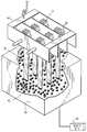
도 7은 도 6과 유사한 도면으로서 버킷 선단에 제공된 덧땜 용접물을 응력 제거를 위한 유동층 내측으로 침지시키는 상태를 도시하는 도면,FIG. 7 is a view similar to FIG. 6 showing a state of immersing the soldering weld provided at the tip of the bucket into the fluidized bed for stress relief; FIG.
도 8은 버킷의 선단에 제공된 덧땜 용접물을 도시하는 개략적인 확대도,8 is a schematic enlarged view showing the overhead weldment provided at the tip of a bucket;
도 9는 장부를 형성하도록 덧땜 용접물을 연마하기 위한 CNC 기계의 개략도,9 is a schematic diagram of a CNC machine for polishing an overlay weldment to form a tenon;
도 10은 선단 상의 마무리 가공된 장부를 도시하는 버킷 선단의 사시도.10 is a perspective view of a bucket tip showing the finished tenon on the tip.
도면의 주요부분에 대한 부호의 설명DESCRIPTION OF THE REFERENCE NUMERALS
12 : 고정 장치 14 : 테이블12: fixing device 14: table
16 : 유도 가열 코일 18 : 로봇16: induction heating coil 18: robot
20 : 용접 헤드 22 : 클램프20: welding head 22: clamp
28, 42 : 아암 43 : 용접 재료28, 42: arm 43: welding material
44 : 제어기 50 : 온도 센서(스캐너)44: controller 50: temperature sensor (scanner)
60 : 지지대 62 : 유동층60: support 62: fluidized bed
76 : 장부76: ledger
본 발명은 터빈 버킷의 선단에 있는 손상된 장부(tenons)를 보수하기 위한 장치 및 방법에 관한 것이며, 특히 제작 주기, 비용, 및 노동력을 감소시키는 반면에 품질을 개선시킬 수 있는, 부식된 장부를 보수하기 위한 장치 및 방법에 관한 것이다.FIELD OF THE INVENTION The present invention relates to an apparatus and method for repairing damaged tenons at the tip of a turbine bucket, and in particular to repairing corroded books that can improve quality while reducing production cycles, costs, and labor. An apparatus and method for
터빈 버킷, 예를 들어 스팀 터빈 버킷(steam turbine bucket)에는 통상적으로 버킷의 선단 위에 놓이는 환형 커버가 제공된다. 상기 커버는 버킷의 반응을 감쇄시키고 유연하게 하는데 사용되며, 또한 주위에 시일이 제공될 수 있는 환형 밴드를 제공한다. 상기 커버는 통상적으로 복수의 버킷 선단 위에 놓이는 아치형 세그먼트로 제공된다. 최초 제작된 버킷에서는 하나 이상의 버킷이 버킷 선단으로부터 돌출되어 있었으며 커버 내부의 대응하는 개구 내부에 수용되었었다. 장부는 커버를 버킷에 유지시키도록 핀(peen) 가공되거나 고정된다. 터빈, 특히 스팀 터빈의 사용기간이 초과되고 연장되면, 버킷 장부는 부식되어 없어지므로 장부를 보수하고 커버를 버킷 선단에 재고정함으로써 버킷/커버 조립체를 개수할 필요가 있다.Turbine buckets, for example steam turbine buckets, are typically provided with an annular cover that lies on the tip of the bucket. The cover is used to dampen and flex the reaction of the bucket and also provides an annular band that can be provided with a seal around. The cover is typically provided in an arcuate segment overlying a plurality of bucket tips. In the original bucket, one or more buckets protruded from the bucket tip and were housed inside the corresponding openings inside the cover. The tenon is pinned or secured to hold the cover in the bucket. When the service life of a turbine, in particular a steam turbine, is exceeded and extended, the bucket tenon becomes corroded and thus it is necessary to repair the tenon and refit the cover to the bucket tip to repair the bucket / cover assembly.
종래에는 버킷 장부를 보수하기 위해, 각각 작업대 위에 놓여져 있는 버킷이 터빈으로부터 제거되었었다. 그 후 부식된 장부가 넙(nub) 아래로 연마되어 떨어지거나 버킷 선단과 일직선상에 놓이게 된다. 장부의 선단은 예열 및 세정된다. 그 후 용접 재료가 다중 패드 방식으로 장부 선단에 수동으로 도포되는데, 이때 예열 양에 엄격한 주의가 요망된다. 그 후 덧땜 용접물은 응력제거되고 기계 가공되어 새로운 또는 보수된 장부를 형성하게 된다. 이와 같이 종래의 공정은 수동으로 수행되고, 지루하고, 고비용이 소요됨으로써 생산성이 매우 낮았었다.Conventionally, in order to repair bucket books, buckets each resting on a workbench have been removed from the turbine. The corroded tenon is then ground down under the nubs, or placed in line with the bucket tip. The tip of the tenon is preheated and cleaned. The welding material is then manually applied to the tenon tip in a multi-pad fashion, with strict attention to the amount of preheating. The overlay weld is then destressed and machined to form a new or repaired tenon. As such, conventional processes were performed manually, tedious and costly, resulting in very low productivity.
따라서, 본 발명은 주기적인 제작 시간, 비용 및 노동력을 감소시키고 보수 공정을 자동화함으로써 품질을 개선하기 위한 장치 및 방법을 제공하고자 하는 것이다.Accordingly, the present invention seeks to provide an apparatus and method for improving quality by reducing periodic manufacturing time, cost and labor and automating the repair process.
본 발명의 한 일면으로서, 고정 장치, 바람직하게 테이블은 버킷 그룹, 예를 들어 각각 4개의 버킷을 한 그룹으로 하는 2개의 그룹을 테이블에 클램핑 고정하기 위한 복수의 클램프를 포함한다. 상기 버킷은 테이블 상의 사전 결정된 위치에 클램프 고정된다. 한 그룹의 버킷은 용접 재료가 다른 그룹의 버킷의 선단에 로봇 이송되는 용접 헤드를 사용하여 다중 패스 방식에 의해 순차적으로 도포되는 동안에 바람직하게 유도 코일에 의해 예열된다. 용접 재료는 다음 용접 패스를 수행하기 위해 각각의 버킷 선단이 충분히 예열되었는지를 확인하기 위해 각각의 버킷 선단에 대한 온도 측정 후에 다중 패스 방식으로 도포된다. 버킷 그룹에 대한 덧땜 용접이 완료되면, 버킷은 테이블 고정 장치로부터 제거되어 다른 고정 장치에 역전된 위치로 놓이며 응력 제거를 위해 유동층 내에 놓이게 된다. 테이블 고정 장치도 로봇 아암에 의해 이송된 용접 헤드와 관련된 용접 위치로 예열된 다른 그룹의 버킷을 위치시켜 예열된 다음 그룹의 버킷 선단에 다중 패스 방식으로 용접 재료가 순차적으로 도포되도록 변위된다. 거의 동시에, 다른 그룹의 버킷은 테이블 고정 장치에 클램프 고정되어 유도 코일에 의해 예열된다. 상기 공정은 손상된 모든 장부에 응력 제거된 충분한 덧땜 용접물이 제공될 때까지 반복된다. 응력 제거 후에, 각각의 버킷 선단에 있는 덧땜 용접물은 바람직하게 CNC 기계에 의해 기계 가공되어 교환 장부를 형성하게 된다.In one aspect of the invention, the fixing device, preferably the table, comprises a plurality of clamps for clamping a bucket group, for example two groups each of four buckets as a group. The bucket is clamped in a predetermined position on the table. The buckets of one group are preferably preheated by an induction coil while the welding material is applied sequentially by a multipass method using a welding head robotically transported to the tip of the buckets of the other group. The welding material is applied in a multiple pass fashion after temperature measurements on each bucket tip to ensure that each bucket tip is sufficiently warmed up to perform the next weld pass. Once the soldering welding to the bucket group is complete, the bucket is removed from the table fixture and placed in an inverted position in the other fixture and placed in the fluidized bed for stress relief. The table fixture is also displaced to position the buckets of another group preheated to the welding position associated with the welding head transferred by the robotic arm so that the welding material is sequentially applied in a multipass fashion to the bucket ends of the groups that are preheated. At about the same time, buckets of different groups are clamped to the table fixture and preheated by the induction coil. The process is repeated until all the damaged books are provided with sufficient overt welded stress relief. After the stress relief, the overlay weld at each bucket tip is preferably machined by a CNC machine to form an exchange ledger.
버킷은 개개의 클램프에 의해 사전 결정된 위치에 처음으로 고정되지만 반드시 회전식 테이블에 고정될 필요는 없다. 예열 후, 용접 재료는 다중 패스 방식으로 예열된 버킷 선단에 로봇에 의해 순차적으로 도포될 수 있으며 계속해서 응력 제거되고 기계 가공된다. 응력 제거는 본 명세서에서 구체적으로 설명한 기술을 포함한 공지의 다양한 기술 중 임의의 한 기술에 의해 수행될 수 있다.The bucket is first fixed in a predetermined position by the individual clamps but does not necessarily need to be fixed to the rotary table. After preheating, the welding material can be applied sequentially by the robot to the bucket tip preheated in a multi-pass manner and subsequently destressed and machined. Stress relief can be performed by any one of a variety of known techniques, including those specifically described herein.
본 발명에 따른 바람직한 실시예에서, 터빈 버킷의 선단에 있는 장부를 보수하기 위한 방법이 제공되며, 상기 방법은 (a) 복수의 버킷을 고정 장치의 사전 결정된 위치에 해제 가능하게 고정하는 단계와, (b) 상기 터빈 버킷을 예열하는 단계와, (c) 제 1 용접 패스로서 상기 고정 장치에 고정된 예열된 버킷의 선단에 용접 재료를 순차적으로 도포하는 단계와, (d) 하나 이상의 추가의 용접 패스로서 상기 고정 장치에 고정된 상기 버킷의 선단에 추가의 용접 재료를 순차적으로 도포하는 단계와, (e) 상기 버킷의 응력을 제거하는 단계, 및 (f) 상기 버킷 선단에 장부를 형성하도록 도포된 용접 재료를 기계 가공하는 단계를 포함한다.In a preferred embodiment according to the invention, a method is provided for repairing a tenon at the tip of a turbine bucket, the method comprising the steps of (a) releasably securing a plurality of buckets to a predetermined position of a fixing device; (b) preheating the turbine bucket, (c) sequentially applying welding material to the tip of the preheated bucket secured to the fixture as a first welding pass, and (d) one or more additional welds Sequentially applying additional welding material to the tip of the bucket secured to the fixing device as a pass, (e) removing the stress of the bucket, and (f) applying to form a tenon at the tip of the bucket Machining the welded material.
다른 바람직한 실시예에서, 터빈 버킷의 선단에 있는 장부를 보수하는 방법이 제공되며, 상기 방법은 (a) 복수의 버킷을 사전 결정된 위치에 고정하는 단계와, (b) 상기 터빈 버킷을 예열하는 단계와, (c) 상기 버킷이 사전 결정된 위치에 고정되어 있는 동안에 제 1 용접 패스로서 상기 고정 장치에 고정된 예열된 버킷의 선단에 용접 재료를 순차적으로 도포하는 단계와, (d) 상기 버킷이 사전 결정된 위치에 고정되어 있는 동안에 하나 이상의 추가의 용접 패스로서 상기 버킷의 선단에 추가의 용접 재료를 순차적으로 도포하는 단계와, (e) 상기 버킷의 응력을 제거하는 단계, 및 (f) 상기 버킷 선단에 장부를 형성하도록 도포된 용접 재료를 기계 가공하는 단계를 포함한다.In another preferred embodiment, a method is provided for repairing a tenon at the tip of a turbine bucket, the method comprising: (a) securing a plurality of buckets to a predetermined position; and (b) preheating the turbine bucket. And (c) sequentially applying welding material to the tip of the preheated bucket fixed to the fixing device as a first welding pass while the bucket is held in a predetermined position; and (d) the bucket is pre-set. Sequentially applying additional welding material to the tip of the bucket as one or more additional welding passes while held in the determined position, (e) relieving the bucket, and (f) the bucket tip Machining the applied welding material to form a tenon.
본 발명의 또 다른 바람직한 실시예에서, 버킷 선단에 하나 이상의 장부를 형성하도록 터빈 버킷의 선단에 용접 재료를 도포하는 조립체가 제공되며, 상기 조립체는 제 1 및 제 2 그룹의 버킷을 고정 장치 상의 사전 결정된 위치에 해제 가능하게 고정하는 클램프를 갖춘 고정 장치와, 상기 버킷을 예열하는 유도 코일과, 상기 버킷의 선단에 용접 재료를 도포하는 용접 헤드를 포함하며, 상기 고정 장치는 제 1 위치와 제 2 위치 사이에서 이동할 수 있으며, 제 1 위치에 있는 고정 장치는 용접 재료가 상기 버킷의 선단에 도포될 수 있게 하는 용접 헤드에 인접되게 제 1 그룹의 버킷을 위치시키고 상기 버킷 선단을 예열하는 유도 코일에 인접되게 제 2 그룹의 버킷을 위치시키며, 제 2 위치에 있는 고정 장치는 용접 재료가 제 2 그룹의 버킷 선단에 도포될 수 있게 하는 용접 헤드에 인접되게 제 2 그룹의 버킷을 위치시킨다.In another preferred embodiment of the present invention, an assembly is provided for applying welding material to the tip of a turbine bucket to form one or more tenons at the tip of the bucket, the assembly preforming the first and second groups of buckets on the holding device. A fixing device having a clamp for releasably fixing at the determined position, an induction coil for preheating the bucket, and a welding head for applying welding material to the tip of the bucket, the fixing device having a first position and a second position. A fixing device in a first position, which can move between positions, locates the first group of buckets adjacent to the welding head allowing welding material to be applied to the tip of the bucket and to an induction coil that preheats the bucket tip. Positioning the second group of buckets adjacently, the securing device in the second position allows welding material to be applied to the bucket tip of the second group. To be close to the weld head to place the bucket in the second group.
도면, 특히 도 1을 참조하면, 보수 시간은 감소시키면서 품질을 높일 수 있는 높은 생산율로 터빈 버킷의 선단에 덧땜 용접 재료를 예열 및 도포하기 위한 조립체가 도면 부호(10)로 도시되어 있다. 도 1에 도시된 조립체는 수직 축 주위에 회전가능하게 장착되는 테이블(14)을 갖춘 고정 장치(12)를 포함한다. 상기 조립체는 또한 유도 가열 코일(16) 및 용접 헤드(20)가 장착된 로봇(18)을 포함한다.Referring to the drawings, in particular with reference to FIG. 1, there is shown an
특히, 테이블(14)은 복수의 직립형 기계식 오버-센터 클램프(22)를 포함한다. 상기 클램프는 테이블(14)에 의해 이송된 직립체(24) 상에 장착되며 스톱(26) 및 가동 아암(28)을 포함한다(도 2 및 도 3). 상기 클램프(22)는 통상적인 것이며 스톱(26)에 대해 버킷(30)의 상단부를 사전 결정된 위치에 클램프 고정하는데 사용된다. 버킷(30)은 플랫폼(32) 및 더브테일(34)을 포함하며, 상기 더브테일(34)은 테이블(14)의 상부에 놓이는 반면에 버킷(30)의 상단부는 도 3에 도시한 바와 같이 아암(28)과 스톱(26) 사이에 클램프 고정된다. 상기 클램프(22)에는 핸들(36)이 제공되는데, 상기 핸들에 의해 클램프는 도 4에 도시한 바와 같이, 버킷을 사전 결정된 위치에 클램프 고정시키도록 수동으로 위치될 수 있다.In particular, the table 14 comprises a plurality of upright mechanical over-center
도 1에 도시한 바와 같이, 클램프(22)는 테이블(14)의 대향 측면을 따라서 각각 4개의 클램프씩 2 그룹으로 배열된다. 각각의 클램프 그룹에 있는 몇몇 또는 다수의 클램프(22)[따라서, 버킷(30)]가 제공될 수 있으며 각각의 그룹의 클램프들은 테이블의 대향 측면을 따라 정렬되지는 않지만 서로에 대해 상이한 각도 방위에서 정렬될 수 있다. 테이블(14)은 클램프 그룹, 따라서 유도 가열 코일(16)에 인접한 각각의 위치에 있는 클램프 고정된 버킷 및 로봇(18), 그리고 특히 로봇(18)에 의해 이송되는 용접 헤드(20)를 위치시키도록 중심 수직축을 중심으로 피봇될 수 있다. 도시된 바람직한 실시예에서, 클램프는 테이블(14)의 대향 측면을 따라서 장착되며, 따라서 테이블(14)은 각각의 버킷 그룹을 유도 가열 코일(16)에 인접되게, 그리고 용접 위치의 용접 헤드(20)에 인접되게 위치시키기 위한 위치들 사이에서 180°회전함으로써 용접 헤드(20)가 각각의 버킷 그룹에 있는 각각의 버킷의 선단에 덧땜 용접물을 제공할 수 있게 된다. 상기 테이블(14)은 테이블을 고정 스탠션에 로킹하는 코너 핀(40)에 의해 두 개의 회전가능한 각각의 위치에 로크될 수 있다.As shown in FIG. 1, the
상기 유도 가열 코일(16)은 클램프(22)에 의해 테이블에 클램프 고정되는 버킷 그룹에 인접되게 테이블(14)의 한 측면에 놓인다. 유도 가열 코일(16)은 버킷과의 접촉 없이 버킷을 예열함으로써 버킷 선단에 인접한 에어포일의 횡단면이 실질적으로 균일하게 가열된다. 바람직하게, 상기 유도 가열 코일은 버킷 에어포일을 약 450℉로 예열한다. 로봇(18)은 조정 아암(42), 상기 아암의 선단으로 이송된 용접 헤드(20)의 운동을 제어하는 제어기(44) 및 상기 터빈 버킷의 선단에 덧땜 용접물을 제공하기 위해 불활성 가스 분위기를 제공하는 가스 컵(46)을 포함하는 통상적인 구성을 취할 수 있다. 로봇은 버킷 선단이 용접 위치에 위치될 때 버킷의 선단에 용접 재료(43)를 도포하도록 프로그램될 수 있다고 이해해야 한다. 따라서, 로봇은 테이블(14)에 클램프 고정된 버킷 선단의 다양한 위치에서 한 측면을 따라 버킷 선단에 순차적으로 용접 재료를 도포하도록 프로그램될 수 있다. 또한, 이후에 설명되는 이유로, 로봇은 적외선 센서도 갖추고 있어서 각각의 버킷 선단의 온도를 용접 이전에 확인할 수 있다. 로봇(18)은 미국 오하이오 팁 시티에 소재하는 다이헨 인코포레이티드(Daihen, Inc.)에 의해 제작되고 시판되는 상표명 OTC-Almega X 시리즈일 수 있다.The
도 6 및 도 7을 참조하면, 버킷의 디펜딩 선단(depending tip)에 덧땜 용접 재료를 역전 자세로 갖추고 있는 버킷을 지지하기 위한 추가의 고정 장치 또는 지지대(60)가 제공되어 있다. 따라서, 충분한 덧땜 용접 재료가 버킷 그룹에 도포되면, 버킷은 테이블 상의 클램프 고정된 위치로부터 수동으로 제거되어 상기 지지대(60)에 삽입된다. 도 7에서, 상기 지지대(60)는 덧땜 용접물을 가지며 유동층 내부에 침지되는 버킷 선단을 포함한다. 상기 유동층(62)은 용기를 유지하는 소형 금속 또는 세라믹 비드를 포함하며 상기 비드 주위 및 내부에서 상향으로 유동되고 용기의 상부를 통해 외측으로 유동되도록 용기(62)의 바닥으로 공급되는 가열된 공기에 의해 용기(62) 내부에서 유동화되는 형태일 수 있다. 도면 부호(64)로 개략적으로 도시한 예열된 공기의 공급은 도시하지 않은 전기로 또는 가스로에 의해 제공되어 용기(62) 내측으로 유입될 수 있다. 각각의 버킷 선단 선단에 덧땜 용접 재료를 포함하는 버킷의 선단을 용기(62) 내측으로 침지시킴으로써, 실질적으로 균일한 온도를 버킷에 가하게 되어 고온의 버킷으로부터 응력을 제거하게 된다. 일단 응력 제거가 수행되면, 도 8에 도시된 덧땜 용접물은 도 9에 개략적으로 도시된 예를 들어 CNC 기계에 의해 순차적으로 기계 가공되어 도 10에 도시된 버킷 장부(76)를 형성한다.With reference to FIGS. 6 and 7, an additional fixture or
이후, 버킷 상의 장부를 개수하는 공정에 대해 설명한다. 이해할 수 있는 바와 같이, 터빈, 특히 스팀 터빈의 규정 시간 초과 사용으로 시초에 제조된 장부가 마모되고 부식되어 없어져, 새로운 장부의 제공을 위해 버킷을 개수하고 개수된 버킷에 커버가 고정되게 할 필요가 있다. 따라서, 마모 또는 부식된 장부를 갖는 버킷은 터빈으로부터 제거되고 손상된 장부는 도시하지 않은 연마 작업에 의해 버킷 선단으로부터 제거된다. 일단 버킷 선단이 실질적으로 평탄한 형상으로 연마되면, 버킷은 개수 준비가 된 것이다.The process of repairing the books on the bucket will now be described. As can be appreciated, over timed use of turbines, in particular steam turbines, may lead to wear and corrosion of the original manufactured books, which necessitates repairing the buckets and securing the covers to the numbered buckets to provide new books. . Thus, a bucket with a worn or corroded tenon is removed from the turbine and the damaged tenon is removed from the bucket tip by a polishing operation not shown. Once the bucket tip is ground to a substantially flat shape, the bucket is ready for repair.
버킷이 테이블(14) 위에 직립 방위로 배열되며 더브테일(34)이 테이블 위에 놓여진다. 버킷 에어포일의 상단부는 클램프(22)에 의해 테이블 위의 사전 결정된 위치에 클램프 고정된다. 도시된 실시예에서, 제 1 그룹의 버킷은 테이블의 한 측면, 예를 들어 유도 가열 코일(16)에 인접한 테이블 측면을 따라 클램프 고정된다. 버킷은 로봇(18) 내측의 프로그램된 위치에 대응하는 사전 결정된 위치에 클램프 고정되어서 제 1 그룹의 예열된 버킷이 용접 헤드(20)에 인접한 용접 위치로 회전운동할 때 로봇이 예정된 용접 위치에 덧땜 용접물을 도포할 수 있게 된다. 제 1 그룹의 버킷이 유도 가열 코일(16)에 인접한 사전 결정된 위치에 클램프 고정되면, 코일(16)은 버킷을 예정 온도, 예를 들어 450℉로 예열하도록 작동된다. 예정된 온도에 도달하면, 테이블(14)은 수직축 주위에서, 예들 들어 약 180℃로 회전하여, 예열된 버킷을 용접 위치에 위치시킨다. 일단 테이블이 회전되면, 제 2 그룹의 버킷이 유도 가열 코일(16)에 인접한 측면을 따라 테이블에 클램프 고정된다. 제 1 그룹의 버킷이 용접 위치에 있고 덧땜 용접 재료가 버킷 선단에 도포되는 동안에, 제 2 그룹의 버킷은 유도 가열 코일(16)에 의해 테이블의 대향 측면을 따라 예열된다.Buckets are arranged in an upright orientation on the table 14 and dovetails 34 are placed on the table. The upper end of the bucket airfoil is clamped in a predetermined position on the table by
제 1 그룹의 버킷이 용접 위치에 있는 경우에, 로봇(18)은 덧땜 용접물을 각각의 예열된 버킷 선단에 순차적으로 도포하도록 작동된다. 특히, 로봇(18)은 가스 컵(46)을 포함하는 용접 헤드(20)를 도 5에 도시한 바와 같이 예열된 버킷 선단의 근처에 위치시키도록 작동된다. 적외선 스캐너(50)는 버킷 선단을 스캔하여 버킷 선단에 적절한 예열이 유지되어 용접 재료의 도포를 가능하게 보장한다. 상기 용접 기술은 많은 용접 기술 중에 하나일 수 있다. 예를 들어, MIG 시스템을 사용하면, 와이어는 가스 컵 상의 딤블을 통해 연속적으로 공급되며 CO2 또는 아르곤 가스 또는 이들의 혼합물이 용접물을 덮도록 분산된다. 이러한 실드 가스는 상기 가스 분위기를 몰아내어 용접 헤드를 차폐함으로써, 용접 재료가 버킷 선단에 도포될 수 있게 한다. 예정된 양의 덧땜 용접 재료를 도포하면, 로봇의 패턴 기억 제어에 의해 덧땜 용접 재료의 도포 공정이 반복되는 제 1 그룹의 버킷의 제 1 버킷 선단으로부터 제 2 버킷 선단으로 로봇 아암이 용접 헤드를 이동시키게 된다. 상기 스캔은 온도를 판독하고, 적절하다면 덧땜 용접 재료를 제 2 버킷 선단에 도포한다. 로봇은 제 1 패스로서 덧땜 용접 재료를, 테이블 위의 사전 결정된 위치 및 용접 위치에 제 1 그룹의 버킷에 있는 각각의 버킷 선단에 도포하도록 순서가 정해져 있다. 덧땜 용접 재료의 도포는 버킷에 의해 흡수될 열량을 규제하도록 제한되어 있다. 적외선 스캐너는 용접 재료를 도포하기 이전에 각각의 버킷 선단에서 온도를 모니터링한다. 모니터링된 온도가 너무 높으면, 로봇은 적절한 온도에 도달할 때까지 용접 시퀀스를 중지한다. 역으로, 선단 온도가 적절한 용접을 위해 너무 낮다면, 추가의 열이 공급될 수 있다.In the case where the first group of buckets are in the welding position, the
덧땜 용접 재료를 제 1 그룹에 있는 각각의 버킷 선단의 용접 위치에 도포하는 제 1 패스의 완료시, 로봇은 제 2 패스로서 각각의 버킷 선단을 따라 추가의 용접 재료를 제공하도록 아암을 변위시킨다. 따라서, 추가의 덧땜 용접 재료가 제 1 패스와 유사하게 각각의 버킷 선단에 순서대로 제공된다. 계속해서, 필요한 덧땜 용접 재료가 얻어질 때까지 다중 용접 패스가 수행된다.Upon completion of the first pass of application of the braze welding material to the weld position of each bucket tip in the first group, the robot displaces the arm to provide additional welding material along each bucket tip as the second pass. Thus, additional braze welding material is provided in sequence at each bucket tip, similar to the first pass. Subsequently, multiple welding passes are performed until the required brazing welding material is obtained.
시퀀스 및 고정 작업은 두 개의 기능을 제공한다는 것을 이해할 것이다. 첫째로, 각각의 용접 초기에 용접 헤드를 각각의 버킷 선단에 대해 동일한 위치에 위치시켜서 도포된 용접 재료의 일관성을 보장하게 한다. 둘째로, 용접 공정 중에 발생된 열이 전도에 의해 재료를 통해 분산 및 이동될 수 있는 적절한 시간을 보장한다. 버킷 온도의 모니터링과 함께 이러한 타이밍 및 시퀀싱은 온도의 안정적 제어를 제공하여 생산성을 증가시키게 한다.It will be appreciated that sequencing and pinning operations provide two functions. Firstly, at the beginning of each weld, the weld head is positioned at the same position relative to each bucket tip to ensure consistency of the applied weld material. Secondly, it ensures adequate time for heat generated during the welding process to be dissipated and moved through the material by conduction. This timing and sequencing, along with monitoring of bucket temperature, provides stable control of temperature to increase productivity.
일단 덧땜 용접이 제 1 그룹의 버킷에 완료되면, 버킷은 테이블(14)로부터 제거되고 지지대(60)에 거꾸로 위치된다. 제 1 그룹의 버킷을 테이블(14)로부터 제거하면, 테이블(14)은 회전하여 다음 그룹의 버킷을 테이블 반대쪽의 용접 위치에 위치시킨다. 제 2 및 그 다음 그룹의 버킷은 적절한 용접 온도로 예열되며 상기 용접 공정이 반복된다. 추가의 버킷도 이전에 예열된 그룹의 버킷이 용접될 때 추가의 버킷을 예열하도록 유도 코일(16)에 인접한 직전에 비워진 사전 결정된 위치에 위치된다.Once the soldering welding is completed on the first group of buckets, the bucket is removed from the table 14 and placed upside down on the
적절한 덧땜 용접물을 갖춘, 테이블(14)로부터 제거된 제 1 그룹의 버킷은 지지대(60)에 놓인다. 지지대(60)는 버킷을 역전된 자세로 유지하여 버킷이 응력 제거를 위한 유동층(62) 내측에 침지될 수 있게 한다. 응력 제거 후에, 예를 들어 약 20 분 후에 버킷은 유동층으로부터 제거되고 도시하지 않은 절연 블랭크로 씌워져 서서히 냉각된다. 냉각 후에, 버킷 선단 상의 덧땜 용접 재료는 예를 들어, CNC 기계에 의해 순차적으로 기계 가공되어 장부(76)를 형성한다. 기계 가공 후에, 버킷은 완전히 새로운 것으로 개수 및 복원되어 버킷 커버가 버킷 선단에 적용될 수 있게 한다.The first group of buckets removed from the table 14, with the appropriate brazing weldment, is placed on the
현재 가장 실용적이고 바람직한 실시예라고 생각되는 것과 관련하여 본원 발명을 설명하였지만, 본원 발명은 설명된 실시예에만 한정되는 것이 아니며, 반대로 본원 청구범위의 사상 및 범주 내에 포함된 다양한 변형예 및 균등한 실시예들을 포함하는 것이라고 이해해야 한다.While the present invention has been described in connection with what is presently considered to be the most practical and preferred embodiment, it is to be understood that the invention is not limited to the described embodiments, but on the contrary various modifications and equivalent implementations included within the spirit and scope of the claims herein. It should be understood to include examples.
본 발명에 따른 장치와 방법에 의해, 터빈 버킷 상의 장부를 보수하는 공정을 자동화함으로써 장부의 제작 시간, 비용 및 노동력이 감소되고 품질 및 생산성이 증가되는 효과가 있다.The apparatus and method according to the present invention have the effect of reducing the production time, cost and labor of the books and increasing the quality and productivity by automating the process of repairing the books on the turbine bucket.
Claims (11)
Applications Claiming Priority (2)
| Application Number | Priority Date | Filing Date | Title |
|---|---|---|---|
| US10/806,426 US7034262B2 (en) | 2004-03-23 | 2004-03-23 | Apparatus and methods for repairing tenons on turbine buckets |
| US10/806,426 | 2004-03-23 |
Publications (2)
| Publication Number | Publication Date |
|---|---|
| KR20060044537A KR20060044537A (en) | 2006-05-16 |
| KR101169075B1 true KR101169075B1 (en) | 2012-07-26 |
Family
ID=34887648
Family Applications (1)
| Application Number | Title | Priority Date | Filing Date |
|---|---|---|---|
| KR1020050023572A KR101169075B1 (en) | 2004-03-23 | 2005-03-22 | Apparatus and methods for repairing tenons on turbine buckets |
Country Status (5)
| Country | Link |
|---|---|
| US (2) | US7034262B2 (en) |
| EP (1) | EP1582289B1 (en) |
| JP (1) | JP4740620B2 (en) |
| KR (1) | KR101169075B1 (en) |
| CN (1) | CN1683750B (en) |
Families Citing this family (35)
| Publication number | Priority date | Publication date | Assignee | Title |
|---|---|---|---|---|
| JP2006247677A (en) * | 2005-03-09 | 2006-09-21 | Fanuc Ltd | Laser welding instruction device and method |
| US20070084051A1 (en) * | 2005-10-18 | 2007-04-19 | General Electric Company | Methods of welding turbine covers and bucket tips |
| US7918024B2 (en) * | 2006-01-20 | 2011-04-05 | General Electric Company | Methods and apparatus for manufacturing components |
| US20080058990A1 (en) * | 2006-08-31 | 2008-03-06 | General Electric Company | Robotic programming control using multiple binary input |
| JP2008238320A (en) * | 2007-03-27 | 2008-10-09 | Fanuc Ltd | Robot having working tool |
| SG155788A1 (en) * | 2008-03-18 | 2009-10-29 | Turbine Overhaul Services Pte | Methods and apparatuses for correcting twist angle in a gas turbine engine blade |
| WO2010033742A2 (en) * | 2008-09-18 | 2010-03-25 | Baker Hughes Incorporated | Method and apparatus for the automated application of hardfacing material to rolling cutters of earth-boring bits |
| US9439277B2 (en) | 2008-10-23 | 2016-09-06 | Baker Hughes Incorporated | Robotically applied hardfacing with pre-heat |
| US8450637B2 (en) | 2008-10-23 | 2013-05-28 | Baker Hughes Incorporated | Apparatus for automated application of hardfacing material to drill bits |
| US8948917B2 (en) | 2008-10-29 | 2015-02-03 | Baker Hughes Incorporated | Systems and methods for robotic welding of drill bits |
| US8355815B2 (en) * | 2009-02-12 | 2013-01-15 | Baker Hughes Incorporated | Methods, systems, and devices for manipulating cutting elements for earth-boring drill bits and tools |
| US8616852B2 (en) * | 2009-11-25 | 2013-12-31 | United Technologies Corporation | Welding repair method of an integrally bladed rotor |
| JP5524005B2 (en) | 2010-09-24 | 2014-06-18 | 三菱重工業株式会社 | Weld bead cutting device and radial pin extraction method for steam turbine |
| CZ305366B6 (en) * | 2011-03-31 | 2015-08-19 | Vlastimil Sedláček | Assembly method of turbine stator vanes, their locking by means of shroud and apparatus for making the same |
| US9043011B2 (en) * | 2012-01-04 | 2015-05-26 | General Electric Company | Robotic machining apparatus method and system for turbine buckets |
| FR2990443B1 (en) * | 2012-05-09 | 2014-05-23 | Snecma | METHOD FOR RECHARGING METALLIC PARTS FOR AIRCRAFT TURBOREACTORS, AND LOCAL PROTECTIVE TOOLS FOR IMPLEMENTING THE METHOD |
| US10415390B2 (en) | 2012-05-11 | 2019-09-17 | Siemens Energy, Inc. | Repair of directionally solidified alloys |
| PL220908B1 (en) | 2012-08-09 | 2016-01-29 | Gen Electric | Regeneration of the steam turbine blading carrier using a bonding method in the solid state |
| CN103056687B (en) * | 2012-12-28 | 2015-01-21 | 北京航空航天大学 | Benchmark repair clamp for vane |
| WO2014134041A1 (en) * | 2013-02-28 | 2014-09-04 | United Technologies Corporation | System and method low heat weld |
| ES2522921B2 (en) * | 2013-05-17 | 2015-07-30 | Loxin 2002, S.L. | Head and automatic machining procedure with vision |
| CN103480993B (en) * | 2013-09-27 | 2015-01-28 | 国家电网公司 | Welding method capable of eliminating welding stress and for reloading technological cover plate of turbine |
| CN103561496B (en) * | 2013-11-14 | 2014-12-17 | 北京航空航天大学 | Design method of complex structure electromagnetic induction heating coil |
| CN104191123B (en) * | 2014-05-25 | 2016-03-30 | 浙江正泰电器股份有限公司 | System of electromagnetic positioning clamping device and automated manufacturing system |
| CN105436247A (en) * | 2015-12-07 | 2016-03-30 | 贵州黎阳航空动力有限公司 | Gas compressor whole blade ring correction method |
| CN105364359A (en) * | 2015-12-08 | 2016-03-02 | 浙江兴益风机电器有限公司 | Automatic welding equipment for axial flow fan impeller |
| US10247002B2 (en) | 2016-02-03 | 2019-04-02 | General Electric Company | In situ gas turbine prevention of crack growth progression |
| US10544676B2 (en) | 2016-02-03 | 2020-01-28 | General Electric Company | Situ gas turbine prevention of crack growth progression |
| US10094221B2 (en) | 2016-02-03 | 2018-10-09 | General Electric Company | In situ gas turbine prevention of crack growth progression |
| US10443385B2 (en) | 2016-02-03 | 2019-10-15 | General Electric Company | In situ gas turbine prevention of crack growth progression via laser welding |
| US20170218762A1 (en) | 2016-02-03 | 2017-08-03 | General Electric Company | Situ Gas Turbine Prevention of Crack Growth Progression |
| CN106002260A (en) * | 2016-07-04 | 2016-10-12 | 苏州市国之福自动化设备有限公司 | Welding equipment capable of polishing welding lines |
| CN107717289B (en) * | 2017-11-27 | 2019-07-19 | 柳州丹顺科技有限公司 | A kind of auto parts pattern welding equipment |
| CN108838513B (en) * | 2018-06-20 | 2020-04-17 | 中国民航大学 | Laser processing positioning method |
| CN109807520B (en) * | 2019-04-07 | 2021-06-29 | 武汉市双新汽车零部件有限公司 | Automatic welding manipulator for automobile assembly |
Citations (3)
| Publication number | Priority date | Publication date | Assignee | Title |
|---|---|---|---|---|
| JPS61215402A (en) | 1985-03-20 | 1986-09-25 | Toshiba Corp | Regenerating process for tenon |
| JPH11270302A (en) | 1997-12-19 | 1999-10-05 | United Technol Corp <Utc> | Tooling assembly |
| JP2002242696A (en) | 2000-10-12 | 2002-08-28 | General Electric Co <Ge> | Repairing device and mending method for gas turbine part |
Family Cites Families (4)
| Publication number | Priority date | Publication date | Assignee | Title |
|---|---|---|---|---|
| US4542272A (en) * | 1982-09-28 | 1985-09-17 | The Cross Company | Induction heating device with electronic positioning control |
| EP0389913B1 (en) * | 1989-03-28 | 1998-06-17 | Refurbished Turbine Components Limited | Turbine blade repair |
| DE4141927C2 (en) * | 1991-12-19 | 1995-06-14 | Mtu Maintenance Gmbh | Method and device for welding workpieces |
| US6532656B1 (en) | 2001-10-10 | 2003-03-18 | General Electric Company | Gas turbine engine compressor blade restoration method |
-
2004
- 2004-03-23 US US10/806,426 patent/US7034262B2/en not_active Expired - Fee Related
-
2005
- 2005-02-25 EP EP05251139A patent/EP1582289B1/en not_active Expired - Fee Related
- 2005-03-22 KR KR1020050023572A patent/KR101169075B1/en not_active IP Right Cessation
- 2005-03-22 JP JP2005080918A patent/JP4740620B2/en not_active Expired - Fee Related
- 2005-03-23 CN CN2005100594138A patent/CN1683750B/en not_active Expired - Fee Related
-
2006
- 2006-03-28 US US11/390,235 patent/US7326873B2/en not_active Expired - Fee Related
Patent Citations (3)
| Publication number | Priority date | Publication date | Assignee | Title |
|---|---|---|---|---|
| JPS61215402A (en) | 1985-03-20 | 1986-09-25 | Toshiba Corp | Regenerating process for tenon |
| JPH11270302A (en) | 1997-12-19 | 1999-10-05 | United Technol Corp <Utc> | Tooling assembly |
| JP2002242696A (en) | 2000-10-12 | 2002-08-28 | General Electric Co <Ge> | Repairing device and mending method for gas turbine part |
Also Published As
| Publication number | Publication date |
|---|---|
| CN1683750A (en) | 2005-10-19 |
| US20060191910A1 (en) | 2006-08-31 |
| JP4740620B2 (en) | 2011-08-03 |
| KR20060044537A (en) | 2006-05-16 |
| US7034262B2 (en) | 2006-04-25 |
| JP2005273664A (en) | 2005-10-06 |
| EP1582289A1 (en) | 2005-10-05 |
| US7326873B2 (en) | 2008-02-05 |
| CN1683750B (en) | 2011-06-15 |
| US20050214124A1 (en) | 2005-09-29 |
| EP1582289B1 (en) | 2012-04-11 |
Similar Documents
| Publication | Publication Date | Title |
|---|---|---|
| KR101169075B1 (en) | Apparatus and methods for repairing tenons on turbine buckets | |
| CA1039089A (en) | Method and apparatus for producing a rotor welded together from discs | |
| TWI494178B (en) | Forming process for the hot forming of a steel sheet of a wind power installation rotor blade to be produced | |
| AU2003236395A1 (en) | Method and apparatus for incremental forming | |
| JP2005349478A (en) | Homogeneous welding method for superalloy article | |
| EP1018388B1 (en) | Welding method and apparatus therefor | |
| US20080029927A1 (en) | Method and apparatus for heat-treating an article and a fixture for use in the same | |
| US5031819A (en) | Automatic braze welding apparatus | |
| JP3850929B2 (en) | Gas turbine blade repair method, repair device therefor, and gas turbine blade | |
| EP0133050A1 (en) | Improvements in or relating to methods of repair | |
| CN214602391U (en) | Rotary disc type rotating four-station high-frequency induction brazing robot | |
| JP3718600B2 (en) | Hot plate welding method and hot plate welding device | |
| CN114260535A (en) | Selective soldering system for selective wave soldering of circuit boards comprising a clamping unit for replacing a solder nozzle | |
| JPS62282796A (en) | Welding repair method for blade root part | |
| KR101984752B1 (en) | Welding System For Turbine Blade Repair Welding, And Operating Method Therefor | |
| IL97926A (en) | Automated apparatus and process for tacking small plates on turbo jet engine blades | |
| RU2330750C2 (en) | Method of turbomachine blades repair and device for its implementation | |
| JP3605250B2 (en) | Handling jig for seam welding equipment | |
| CN212652845U (en) | Metal bellows brazing device | |
| US20060027541A1 (en) | Programmable non-contact fusion welding apparatus and method | |
| CN107498134B (en) | Welding device and control method thereof | |
| JP2010082674A (en) | Robot arc welding system and welding operation method of the same | |
| JP3662088B2 (en) | Seam welding equipment | |
| CN208408963U (en) | A kind of hydraulic turbine main shaft welder | |
| KR100315539B1 (en) | Automatic seal-welding machine for the diaphragm of turbine |
Legal Events
| Date | Code | Title | Description |
|---|---|---|---|
| A201 | Request for examination | ||
| E701 | Decision to grant or registration of patent right | ||
| GRNT | Written decision to grant | ||
| LAPS | Lapse due to unpaid annual fee |