KR101131776B1 - Gait generator of legged mobile robot - Google Patents
Gait generator of legged mobile robot Download PDFInfo
- Publication number
- KR101131776B1 KR101131776B1 KR1020077007229A KR20077007229A KR101131776B1 KR 101131776 B1 KR101131776 B1 KR 101131776B1 KR 1020077007229 A KR1020077007229 A KR 1020077007229A KR 20077007229 A KR20077007229 A KR 20077007229A KR 101131776 B1 KR101131776 B1 KR 101131776B1
- Authority
- KR
- South Korea
- Prior art keywords
- target
- robot
- gait
- trajectory
- force
- Prior art date
Links
Images
Classifications
-
- B—PERFORMING OPERATIONS; TRANSPORTING
- B25—HAND TOOLS; PORTABLE POWER-DRIVEN TOOLS; MANIPULATORS
- B25J—MANIPULATORS; CHAMBERS PROVIDED WITH MANIPULATION DEVICES
- B25J13/00—Controls for manipulators
-
- B—PERFORMING OPERATIONS; TRANSPORTING
- B62—LAND VEHICLES FOR TRAVELLING OTHERWISE THAN ON RAILS
- B62D—MOTOR VEHICLES; TRAILERS
- B62D57/00—Vehicles characterised by having other propulsion or other ground- engaging means than wheels or endless track, alone or in addition to wheels or endless track
- B62D57/02—Vehicles characterised by having other propulsion or other ground- engaging means than wheels or endless track, alone or in addition to wheels or endless track with ground-engaging propulsion means, e.g. walking members
- B62D57/032—Vehicles characterised by having other propulsion or other ground- engaging means than wheels or endless track, alone or in addition to wheels or endless track with ground-engaging propulsion means, e.g. walking members with alternately or sequentially lifted supporting base and legs; with alternately or sequentially lifted feet or skid
-
- B—PERFORMING OPERATIONS; TRANSPORTING
- B25—HAND TOOLS; PORTABLE POWER-DRIVEN TOOLS; MANIPULATORS
- B25J—MANIPULATORS; CHAMBERS PROVIDED WITH MANIPULATION DEVICES
- B25J5/00—Manipulators mounted on wheels or on carriages
-
- B—PERFORMING OPERATIONS; TRANSPORTING
- B25—HAND TOOLS; PORTABLE POWER-DRIVEN TOOLS; MANIPULATORS
- B25J—MANIPULATORS; CHAMBERS PROVIDED WITH MANIPULATION DEVICES
- B25J9/00—Programme-controlled manipulators
- B25J9/16—Programme controls
Landscapes
- Engineering & Computer Science (AREA)
- Mechanical Engineering (AREA)
- Robotics (AREA)
- Chemical & Material Sciences (AREA)
- Combustion & Propulsion (AREA)
- Transportation (AREA)
- Manipulator (AREA)
Abstract
대상물 동역학 모델상에서의 대상물(120)의 거동을 실제의 거동에 근접시키기 위한 모델 조작량(추정 외란력)을 대상물 동역학 모델에 부여하면서, 대상물 동역학 모델을 사용하여 현재 이후의 소정 기간의 대상물(120)의 목표 운동궤도와 목표 대상물 반력궤도를 구하고, 이것들을 사용하여 소정 기간의 로봇(1)의 보용을 임시생성한다. 그 보용과 대상물 목표 운동궤도를 기초로 로봇(1)과 대상물(120)과의 간섭 등의 기하학적 제약조건을 체크하고, 그것에 따라 적당하게, 대상물(120)의 이동계획이나 로봇(1)의 보용 패러미터(착지 예정위치 자세 등)를 수정하여, 로봇(1)의 보용을 생성한다. 이것에 의해, 로봇(1)의 동작 제어를 행하면서, 리얼타임으로 실제의 환경조건을 반영시키면서, 로봇(1)과 대상물 사이의 간섭 등에 관계되는 소요의 기하학적 제약조건을 만족시키는 목표 보용을 생성한다.

대상물 동역학 모델, 모델 조작량 결정 수단, 로봇?대상물 간 작용력 궤도 임시결정 수단, 대상물 운동궤도 임시결정 수단, 제약조건 판단 수단, 수정 수단
The object dynamics model is used to give the object dynamics model a model manipulation amount (estimated disturbance force) for approaching the behavior of the object 120 on the object dynamics model to the actual behavior, while the object 120 is subjected to a predetermined period of time after the present time. The target motion trajectory and the target object reaction force trajectory are obtained, and the gait of the robot 1 for a predetermined period is temporarily generated using these. Based on the gait and the target motion trajectory of the object, geometric constraints such as interference between the robot 1 and the object 120 are checked, and accordingly, the movement plan of the object 120 and the gait of the robot 1 are appropriately determined. The parameters (landing position, posture, etc.) are corrected to generate gait of the robot 1. Thereby, while performing the motion control of the robot 1, while generating the target gait that satisfies the required geometrical constraints related to the interference between the robot 1 and the object and the like while reflecting actual environmental conditions in real time. do.
Object dynamics model, model manipulated variable determining means, robot or object acting force temporal determination means, object motion trajectory temporary determination means, constraint determination means, correction means
Description
본 발명은 다리식 이동 로봇에 대상물을 이동시키는 작업을 행하게 하기 위한 목표 보용을, 그 목표 보용에 추종하도록 로봇의 동작을 제어하면서 생성하는 장치에 관한 것이다. The present invention relates to an apparatus for generating a target walk for causing a legged mobile robot to perform an operation of moving an object while controlling the robot's operation to follow the target walk.
2족이동 로봇 등의 다리식 이동 로봇에, 어떤 대상물을 밀어서 이동시키는 등의 작업을 행하게 하는 경우에는, 로봇은 그 다리체의 선단부가 접촉하는 바닥으로부터 상반력(床反力)을 받을 뿐만 아니라, 대상물로부터 반력을 받는다. 이와 같이 대상물로부터 로봇이 받는 반력을 본 명세서에서는 대상물 반력이라고 한다.When a legged mobile robot, such as a biped robot, is used to perform operations such as pushing and moving an object, the robot not only receives the counter force from the floor where the tip of the leg contacts. , Reaction from the object. In this specification, the reaction force received by the robot from the object is referred to as the object reaction force.
이와 같이, 다리식 이동 로봇에 대상물 반력이 작용하는 상태에서 로봇의 보용을 생성하거나, 동작 제어를 행하는 기술로서는, 예를 들면 본원 발명자에 의한 일본 특개평10-230485호 공보(이하, 특허문헌 1이라고 함)에 개시되는 것이 알려져 있다. 이 기술은, 로봇의 운동에 의해 발생하는 관성력과, 로봇에 작용하는 중력 및 대상물 반력과의 합력이 목표 ZMP(목표 상반력 중심점) 주위에 발생하는 모멘트의 연직성분을 제외한 성분(수평성분)이 0이 된다(목표 상반력 중심점에서 작용하는 상반력과 상기 합력이 균형을 이룸)고 하는 동역학적 평형조건을 만족시키도록, 목표 보용을 생성하고, 이 목표 보용에 추종시키도록 로봇의 동작 제어를 행하는 것이다. 또한, 이 기술에서는, 로봇에 작용하는 외력이 예기되지 않은 외력이 되어도(목표 외력과 실외력과의 편차가 어느 정도 커져도), 로봇의 중심위치가 로봇의 운동 밸런스를 유지할 수 있는 중심위치에 평형하도록 로봇의 목표 보용을 조정하도록 하고 있다. As described above, as a technique for generating gait of the robot in the state in which the object reaction force acts on the legged mobile robot or performing motion control, for example, Japanese Patent Application Laid-open No. Hei 10-230485 (hereinafter, Patent Document 1). It is known to disclose). In this technique, the component (horizontal component) of the inertia force generated by the robot's motion and the gravity component acting on the robot and the object reaction force except for the vertical component of the moment generated around the target ZMP (target reaction force center point) A target walk is created to satisfy the dynamic equilibrium condition of zero (the reaction force acting at the target center force center point and the combined force), and the motion control of the robot is followed to follow this target walk. To do. In this technique, even if the external force acting on the robot becomes an unexpected external force (even if the deviation between the target external force and the outdoor force increases to some extent), the center position of the robot is balanced to the center position where the robot's motion balance can be maintained. The robot's target walk is adjusted so that
또, 2족이동 로봇(휴머노이드 로봇)의 거동을 시뮬레이션 하는 것으로서, 일본 로봇학회지/Vol.19/No.1, pp.28~36, 2001/「가상 로봇 플랫폼」(이하, 비특허문헌 1이라고 함)에 개시되는 것이 알려져 있다. Moreover, as a simulation of the behavior of a biped robot (humanoid robot), Japanese Society of Robotics / Vol.19 / No.1, pp.28-36, 2001 / "Virtual Robot Platform" (hereinafter referred to as Non-Patent Document 1). It is known to disclose).
그런데, 대상물을 이동시키는 작업을 행하기 위한 로봇의 목표 보용을 생성하는 경우, 일반적으로, 이 대상물을 이동시키는 환경조건(바닥의 형상, 마찰력 상태 등)을 상정한 뒤에, 대상물의 이동계획(대상물을 어떤 타이밍에서 어떻게 이동시킨다고 하는 것과 같은 계획)을 기초로, 대상물 반력의 궤도(시계열 패턴)나, 대상물의 운동궤도(대상물의 이동위치 및 자세의 시계열 패턴), 로봇의 각 다리체의 선단부의 운동궤도 등을 규정하는 기본적인 보용 생성용의 패러미터가 결정된다. 그리고, 그 결정된 패러미터를 사용하여, 상기 상정한 환경조건하에서 동역학적인 제약조건(예를 들면 상기 동역학적 평형조건을 만족시키고, ZMP가 로봇의 접지면 내에 존재하는 등의 조건)을 만족시키도록 로봇의 목표 보용이 생성된다. By the way, in the case of generating a target walk of a robot for performing a task for moving an object, generally, after assuming environmental conditions (bottom shape, frictional force state, etc.) for moving the object, the movement plan of the object (object On the basis of the track of the reaction force (time series pattern), the motion trajectory of the object (time series pattern of the movement position and posture of the object), and the tip of each leg of the robot. The basic gait generation parameter that defines the motion trajectory and the like is determined. The determined parameters are then used to satisfy the dynamic constraints (e.g., to satisfy the dynamic equilibrium conditions, ZMP is present in the ground plane of the robot, etc.) under the assumed environmental conditions. The target complement of is created.
이 경우, 이동계획이나 보용 생성용의 패러미터가 부적절하면, 로봇의 상체가 대상물에 충돌하지 않고, 대상물에 걸어맞추어지게 하는 로봇의 팔체가 가동범위를 초과하지 않는, 등의 기하학적인 제약조건을 만족시키지 않는 목표 보용이 생성되어 버리는 일이 있다. In this case, if the parameters for movement planning or gait generation are inappropriate, geometric constraints such as the upper body of the robot not colliding with the object and the arm of the robot allowing the robot to engage with the object do not exceed the moving range. A target supplement may be created that you do not want to make.
그래서, 예를 들면 상기 특허문헌 1에 개시되는 기술에 상기 비특허문헌 1에 개시되는 것과 같은 기술을 적용하고, 로봇의 거동의 시뮬레이션을 행하여, 기하학적인 제약조건을 만족시키고 있는지 아닌지를 체크하면서, 목표 보용을 생성하는 것이 고려된다. So, for example, applying the same technique disclosed in the
그러나, 상기 비특허문헌 1에 개시되는 기술은, 어떤 환경조건을 상정한 뒤에, 로봇의 거동을 시뮬레이션 하는(예측하는) 것이기 때문에, 실제의 환경조건과 상정한 환경조건이 상이하면(이러한 상황은 종종 발생함), 생성된 목표 보용에서는 실제로는 상기 기하학적 제약조건이 만족시켜지지 않는다고 하는 상황이 발생하는 일이 많다. However, since the technique disclosed in the
본 발명은 이러한 배경을 감안하여 이루어진 것으로, 로봇의 동작 제어를 행하면서, 리얼타임으로 실제의 환경조건을 반영시키면서, 로봇과 대상물 사이의 간섭 등에 관계되는 소요의 기하학적 제약조건을 만족시키는 목표 보용을 생성할 수 있는 다리식 이동 로봇의 보용 생성장치를 제공하는 것을 목적으로 한다. SUMMARY OF THE INVENTION The present invention has been made in view of such a background, and aims to satisfy target geometrical constraints related to interference between a robot and an object while reflecting actual environmental conditions in real time while performing robot motion control. An object of the present invention is to provide a walk generation apparatus for a legged mobile robot.
본 발명의 다리식 이동 로봇의 보용 생성장치의 제 1 발명은, 이러한 목적을 달성하기 위해서, In order to achieve this object, the first invention of the walk generation apparatus for a legged mobile robot of the present invention
상체로부터 연장하여 설치된 복수의 다리체를 구비하는 다리식 이동 로봇에 대상물을 이동시키는 작업을 행하게 하기 위한 목표 보용을, 이 목표 보용에 추종하도록 로봇을 동작시키면서 생성하는 보용 생성장치에 있어서, In the gait generating device which produces | generates the target walk for making the operation | movement which moves an object to the legged mobile robot which has a some leg body extended extended from an upper body, operating a robot so as to follow this target walk.
대상물에 작용하는 힘과 이 대상물의 운동과의 관계를 나타내는 대상물 동역학 모델과, Object dynamics model showing the relationship between the force acting on the object and the motion of the object,
상기 목표 보용에 추종하도록 로봇을 동작시키고 있을 때의 실제의 대상물의 거동을 관측하면서, 상기 대상물 동역학 모델상에서의 대상물의 거동을 실제의 대상물의 거동에 근접시키기 위해 상기 대상물 동역학 모델에 부여할 모델 조작량을 결정하는 모델 조작량 결정 수단과, The amount of model manipulation to impart to the object dynamics model in order to approximate the behavior of the object on the object dynamics model to the behavior of the actual object while observing the actual object behavior when the robot is operated to follow the target walk. Model manipulated variable determining means for determining a value,
상기 로봇을 추종시킬 새로운 목표 보용을 생성할 때, 상기 결정된 모델 조작량을 상기 대상물 동역학 모델에 부여하면서, 적어도 상기 대상물의 이동계획과 상기 대상물 동역학 모델상에서의 대상물의 운동상태량에 기초하여 이 운동상태량을 상기 이동계획에 기초하는 대상물의 운동상태량에 추종시키도록 현재 이후의 소정 기간에서의 대상물과 로봇 사이의 작용력의 목표 궤도인 로봇?대상물 간 목표 작용력 궤도를 임시결정하는 로봇?대상물 간 작용력 궤도 임시결정 수단과, When generating a new target walk to follow the robot, the determined amount of model manipulation is given to the object dynamics model, and at least based on the movement plan of the object and the amount of motion state of the object on the object dynamics model. Temporarily determine the motion force trajectory between the robot and the object to temporarily determine a target force trajectory between the robot and the object, which is a target trajectory of the action force between the object and the robot in a predetermined period after the present so as to follow the motion state amount of the object based on the movement plan. Sudan,
상기 결정된 모델 조작량을 상기 대상물 동역학 모델에 부여하면서, 상기 임시결정된 로봇?대상물 간 목표 작용력 궤도를 이 대상물 동역학 모델에 입력하고, 이 대상물 동역학 모델에 의해, 상기 소정 기간에서의 대상물의 목표 운동궤도를 임시결정하는 대상물 운동궤도 임시결정 수단과, While the determined model manipulation amount is given to the object dynamics model, the target robot or object target force trajectory is input to the object dynamics model, and the object dynamics model is used to determine the target motion trajectory of the object in the predetermined period. A temporary movement means for temporarily determining an object movement trajectory;
적어도 상기 임시결정된 대상물의 목표 운동궤도와 상기 임시결정된 로봇?대상물 간 목표 작용력 궤도를 기초로, 로봇의 목표 보용을 생성하기 위해서 사용하는 보용 패러미터를 임시결정하고, 그 임시결정한 보용 패러미터를 사용하여 상기 소정 기간에서의 로봇의 목표 보용을 임시생성하는 로봇 보용 임시생성 수단과, Based on at least the target motion trajectory of the temporary object and the target force trajectory between the temporary robot and the object, temporarily determining a gait parameter used to generate a target gait of the robot, and using the temporary gait parameter. A robot walk temporary generation means for temporarily generating a target walk of the robot in a predetermined period;
상기 임시결정한 대상물의 목표 운동궤도와 상기 임시생성한 로봇의 목표 보용의 운동궤도를 기초로, 대상물과 로봇 중 적어도 어느 일방에 관계되는 소정의 기하학적 제약조건이 만족시켜지고 있는지 아닌지를 판단하는 제약조건 판단 수단과, Constraints for determining whether or not predetermined geometric constraints related to at least one of the object and the robot are satisfied based on the target motion trajectory of the temporarily determined object and the motion trajectory of the target walk of the temporarily generated robot. Judgment means,
상기 기하학적 제약조건이 만족시켜지고 있지 않을 때, 상기 이동계획과 상기 임시결정한 보용 패러미터와 상기 임시결정한 대상물의 목표 운동궤도 중 적어도 하나를 수정 대상으로 하여, 이 수정 대상을 상기 기하학적 제약조건이 만족시켜지도록 수정하는 수정 수단을 구비하고, When the geometric constraint is not satisfied, at least one of the movement plan, the temporarily determined gait parameter, and the target trajectory of the temporarily determined object is corrected, and the geometric constraint is satisfied. Has correction means for modifying it to lose,
상기 수정된 수정 대상을 사용하여 상기 새로운 목표 보용을 생성하도록 한 것을 특징으로 하는 것이다. The new target walk is generated by using the modified target to be modified.
이러한 제 1 발명에 의하면, 대상물 동역학 모델(이것은 순동역학(順動力學) 모델임)에 상기 모델 조작량을 주면서, 상기 로봇?대상물 간 작용력 임시결정 수단과 대상물 운동궤도 임시결정 수단에 의해 각각 로봇?대상물 간 목표 작용력 궤도와 대상물의 목표 운동궤도가 임시결정되기 때문에, 이들 로봇?대상물 간 목표 작용력 궤도와 목표 운동궤도는, 현재 이후의 소정 기간에서의 실제의 로봇?대상물 간의 작용력 궤도와 대상물의 운동궤도와의 예측 궤도로서 정확도(신뢰성)가 높은 것이 된다. 또한, 상기 모델 조작량으로서는, 실제의 대상물에 작용하는 힘 중, 로봇 이외로부터 작용하는 외란력(대상물에 바닥으로부터 작용하는 마찰력 등), 혹은 그것을 규정하는 것 등을 들 수 있다. 또, 로봇?대상물 간 목표 작용력 궤도를 임시결정할 때에 추종시키는 운동상태량으로서는, 예를 들면 대상물의 이동속도를 들 수 있다. According to this first invention, the robot and the object are temporarily determined by means of temporarily determining the force between the robot and the object, while giving the model manipulation amount to the object dynamics model (this is the net dynamics model). Since the target force trajectory between the objects and the target motion trajectory of the object are temporarily determined, the target force trajectory and the target motion trajectory between these robots and the object are the actual force trajectory between the robot and the object and the motion of the object in a predetermined period after the present. The prediction trajectory with the trajectory is a high accuracy (reliability). Moreover, as said model operation amount, the disturbance force (frictional force which acts from a floor to an object, etc.) which acts from a robot other than the force which acts on an actual object, etc. are mentioned. In addition, the movement speed of an object is mentioned as an example of the quantity of the motion state to follow when temporarily determining the target force-force trajectory between a robot and an object.
또한, 이와 같이 임시결정된 로봇?대상물 간 목표 작용력 궤도와 대상물의 목표 운동궤도를 기초로, 로봇의 보용 패러미터를 결정하고, 상기 소정 기간에서의 목표 보용을 임시생성하므로, 그 임시생성한 목표 보용도, 현재 이후의 소정 기간에서의 실제의 로봇의 예측 보용으로서 정확도(신뢰성)가 높은 것이 된다. 또한, 보용 패러미터로서는, 로봇의 각 다리체의 운동궤도를 규정하는 패러미터(예를 들면 각 다리체의 착지 예정위치, 착지 예정시각 등), 목표 ZMP 혹은 목표 상반력 중심점의 궤도를 규정하는 패러미터 등을 들 수 있다. 이 경우, 예를 들면 로봇의 각 부의 운동이 발생하는 관성력과 로봇에 작용하는 중력과 로봇?대상물 간 목표 작용력에 의해 정해지고, 대상물에서 로봇으로의 반력과의 합력이 목표 ZMP 주위에 발생하는 모멘트의 수평성분이 0이 된다 라고 하는 소정의 동역학적 평형조건이, 로봇의 동역학 모델(로봇의 운동과 로봇에 작용하는 힘과의 관계를 나타내는 모델) 상에서 만족시켜지도록 보용 패러미터를 기초로 목표 보용을 임시생성하면 된다. In addition, the gait parameters of the robot are determined based on the target force trajectory between the robot and the object and the target motion trajectory of the object, and the target gait is temporarily generated in the predetermined period. The accuracy (reliability) is high as the predictive walk of the actual robot in the predetermined period after the present. As the gait parameters, parameters for defining the motion trajectory of each leg of the robot (e.g., the landing position of each leg, the scheduled landing time, etc.), the parameter defining the trajectory of the target ZMP or the target upper force center point, etc. Can be mentioned. In this case, for example, the moment of the force generated around the target ZMP is determined by the inertia force generated by the movement of each part of the robot and the target action force between the robot and the object and the reaction force from the object to the robot. The target gait is based on the gait parameters so that a predetermined dynamic equilibrium condition, that the horizontal component of 0 becomes zero, is satisfied on the robot's dynamics model (the model representing the relationship between the robot's motion and the force acting on the robot). Temporarily created.
그리고, 상기 임시결정된 대상물의 목표 운동궤도와 상기 임시생성한 로봇의 목표 보용의 운동궤도를 기초로, 상기 소정 기간에서, 대상물과 로봇 중 적어도 어느 일방에 관계되는 소정의 기하학적 제약조건이 만족시켜지고 있는지 아닌지를 판단함으로써, 그 판단을 적정하게 행할 수 있다(신뢰성이 높은 판단을 행할 수 있음). 여기에서, 상기 기하학적 제약조건으로서는, 예를 들면 대상물과 로봇의 상체가 간섭하지 않고, 로봇의 팔체 등 대상물에 걸어맞추어지게 하는 부분의 관절이 가동범위를 초과하는 변위를 하지 않는 등, 대상물과 로봇 사이의 위치?자세관계에 의존하는 기하학적 제약조건이다. And based on the target motion trajectory of the temporarily determined object and the motion trajectory of the target walk of the temporarily generated robot, in the predetermined period, a predetermined geometric constraint relating to at least one of the object and the robot is satisfied. By judging whether or not it is possible, the judgment can be appropriately made (a highly reliable judgment can be made). Here, as the geometric constraint, for example, the object and the upper body of the robot do not interfere, and the joints of the parts to be engaged with the object, such as the arm of the robot, do not displace beyond the movable range. It is a geometric constraint that depends on the position and posture relationship.
또한, 본 발명에서는, 상기의 판단에서 상기 기하학적 제약조건이 충족시켜지지 않을 때에, 상기 이동계획과 보용 패러미터와 상기 임시결정한 대상물의 목표 운동궤도 중 적어도 일방을 수정 대상으로 하여, 상기 기하학적 제약조건이 만족시켜지도록 이 수정 대상을 수정하고, 그 수정한 수정 대상을 사용하여 새로운 목표 보용을 생성한다. 이것에 의해, 상기 기하학적 제약조건을 만족시키는 새로운 목표 보용을 생성할 수 있다. In the present invention, when the geometric constraint is not satisfied in the above determination, at least one of the movement plan, the walking parameter, and the target movement trajectory of the temporarily determined object is corrected, and the geometric constraint is Modify this modifier to be satisfied and create a new target walk using that modifier. This makes it possible to generate a new target walk that satisfies the geometric constraint.
이와 같이 제 1 발명에서는, 로봇의 동작 제어를 행하면서, 로봇의 목표 보용을 생성할 때, 대상물의 실제의 거동을 상기 모델 조작량에 의해 대상물 동역학 모델에 반영시키면서, 장래의(상기 소정 기간에서의) 로봇?대상물 간 목표 작용력 궤도와 대상물의 목표 운동궤도를 임시결정하고, 또한 이것들을 기초로, 로봇의 장래의 목표 보용을 임시결정하므로, 대상물과 로봇의 거동의 신뢰성 높은 예측을 행할 수 있다. 그리고, 그 장래의 대상물의 목표 운동궤도와 목표 보용의 운동궤도를 기초로 상기 기하학적 제약조건이 만족시켜지고 있는지 아닌지를 판단하고, 만족시켜지고 있지 않은 경우에, 이동계획과 보용 패러미터와 상기 임시결정한 대상물의 목표 운동궤도 중 적어도 어느 하나(수정 대상)를 수정한 뒤에, 그 수정 대상을 사용하여 새로운 목표 보용을 생성한다. As described above, in the first invention, when generating the target walk of the robot while controlling the motion of the robot, in the future (in the predetermined period), the actual behavior of the object is reflected in the object dynamics model by the model manipulation amount. ) Since the target force trajectory between the robot and the object and the target motion trajectory of the object are temporarily determined, and based on these, the future target retention of the robot is temporarily determined, so that reliable prediction of the behavior of the object and the robot can be performed. Then, it is judged whether or not the geometric constraint is satisfied based on the target trajectory of the future object and the trajectory of target gait, and if it is not satisfied, the movement plan, the walking parameter and the temporary decision After modifying at least one of the target motion trajectories (object to be modified) of the object, a new target walk is generated using the object to be modified.
이 때문에, 제 1 발명에 의하면, 로봇의 동작 제어를 행하면서, 리얼타임으로 실제의 환경조건을 반영시키면서, 로봇과 대상물 간의 간섭 등에 관계되는 소요의 기하학적 제약조건을 만족시키는 목표 보용을 생성할 수 있다. For this reason, according to the first invention, it is possible to generate a target walk that satisfies the required geometrical constraints related to the interference between the robot and the object while reflecting the actual environmental conditions in real time while controlling the operation of the robot. have.
또한, 이 제 1 발명에서, 수정 후의 수정 대상을 사용하여 목표 보용을 생성하는 경우, 그 수정 대상이 이동계획일 때에는, 새로운 목표 보용을 생성할 때, 예를 들면 상기 로봇?대상물 간 작용력 궤도 임시결정 수단, 대상물 운동궤도 임시결정 수단, 로봇 보용 임시생성 수단과 같은 처리를 차례차례 실행하여 보용 패러미터를 결정하고, 그 결정한 보용 패러미터를 사용하여 로봇의 새로운 목표 보용을 생성하도록 하면 된다. 또, 수정 대상이 보용 패러미터일 때에는, 그 보용 패러미터를 사용하여 로봇의 새로운 목표 보용을 생성하도록 하면 된다. 이 경우, 로봇?대상물 간 목표 작용력 궤도와 대상물의 목표 운동궤도는 상기 임시결정된 것과 동일해도 된다. 또, 수정 대상이 대상물의 목표 운동궤도일 때에는, 상기 로봇 보용 임시생성 수단과 동일한 처리를 실행하여 보용 패러미터를 결정하고, 그 결정한 보용 패러미터를 사용하여 로봇의 새로운 목표 보용을 생성하도록 해도 된다. 이 경우, 대상물의 목표 운동궤도는 수정 후의 것을 사용한다. In addition, in this first invention, when the target gait is generated using the modified target after correction, when the modified target is a movement plan, when a new target gait is generated, for example, the robot or the object has a temporary orbital force trajectory. Processing such as determination means, object motion trajectory temporary determination means, and robot walk temporary generation means may be executed in order to determine the gait parameters, and the new gait parameters for the robot may be generated using the determined gait parameters. When the correction target is a gait parameter, a new target gait for the robot may be generated using the gait parameter. In this case, the target motion force trajectory between the robot and the object and the target motion trajectory of the object may be the same as those determined above. In addition, when the correction target is the target motion trajectory of the object, the same processing as that of the robot temporary construction means may be performed to determine the gait parameters, and the new gait parameters of the robot may be generated using the determined gait parameters. In this case, the target motion trajectory of the object is used after the correction.
또한, 제 1 발명에서는, 바람직하게는, 상기 모델 조작량 결정 수단은, 실제의 대상물에 작용하는 힘 중, 상기 로봇으로부터 대상물에 작용하는 힘 이외의 외란력을 상기 모델 조작량으로서 추정하는 수단이다(제 2 발명). 이 경우에는, 상기 대상물 운동궤도 임시결정 수단에서는, 상기 추정된 외란력(모델 조작량)과, 상기 임시결정된 로봇?대상물 간 목표 작용력 궤도에 의해 정해지는 로봇으로부터 대상물에의 목표 작용력과의 합력을 상기 대상물 동역학 모델에 입력하고, 그 합력과, 이 대상물 동역학 모델의 동역학적 관계를 만족시키는 대상물의 운동궤도를 상기 대상물의 목표 운동궤도로서 결정하도록 하면 된다. Further, in the first invention, preferably, the model manipulated variable determining means is a means for estimating a disturbance force other than the force acting on the target from the robot as the model manipulated variable among the forces acting on the actual object (first 2 invention). In this case, in the target motion trajectory temporary determination means, the combined force of the estimated disturbance force (model manipulation amount) and the target action force from the robot determined by the target force trajectory between the temporarily determined robot and the object is determined. What is necessary is just to input into the object dynamics model, and to determine the motion trajectory of the object which satisfy | fills the combined force and the dynamic relationship of this object dynamics model as a target motion trajectory of the said object.
보충하면, 상기 외란력은 예를 들면 다음과 같이 추정할 수 있다. 즉, 대상물의 실제의 운동속도 또는 가속도를 추정 또는 검출하고, 그 추정값 또는 검출값으로부터 대상물에 실제로 작용하고 있는 힘을 파악한다. 또, 로봇으로부터 대상물에 실제로 작용하고 있는 힘을 추정 또는 검출하고, 그 힘의 추정값 또는 검출값을 상기 파악한 힘으로부터 뺌으로써, 상기 외란력을 추정한다. In addition, the disturbance force can be estimated as follows, for example. That is, the actual motion speed or acceleration of an object is estimated or detected, and the force actually acting on the object is grasped from the estimated value or the detected value. The disturbance force is estimated by estimating or detecting the force actually acting on the object from the robot, and subtracting the estimated value or the detected value of the force from the grasped force.
다음에, 본 발명의 다리식 이동 로봇의 보용 생성장치의 제 3 발명은 상기의 목적을 달성하기 위해서, Next, in order to achieve the above object, the third invention of the walk generation apparatus for the legged mobile robot of the present invention
상체로부터 연장하여 설치된 복수의 다리체를 구비하는 다리식 이동 로봇에 대상물을 이동시키는 작업을 행하게 하기 위한 목표 보용을, 이 목표 보용에 추종하도록 로봇을 동작시키면서 생성하는 보용 생성장치에 있어서, In the gait generating device which produces | generates the target walk for making the operation | movement which moves an object to the legged mobile robot which has a some leg body extended extended from an upper body, operating a robot so as to follow this target walk.
대상물의 운동과 이 대상물에 작용하는 힘과의 관계를 나타내는 대상물 동역학 모델과, An object dynamics model representing the relationship between the motion of the object and the force acting on the object,
상기 목표 보용에 추종하도록 로봇을 동작시키고 있을 때의 실제의 대상물의 거동을 관측하면서, 실제의 대상물에 작용하는 힘 중, 로봇으로부터 대상물에 작용하는 힘 이외의 외란력을 추정하는 외란력 추정 수단과, Disturbance force estimating means for estimating disturbance force other than the force acting on the object from the robot while observing the behavior of the actual object when the robot is operated to follow the target walk; ,
상기 로봇을 추종시킬 새로운 목표 보용을 생성할 때, 적어도 상기 대상물의 이동계획에 기초하여 현재 이후의 소정 기간에서의 대상물의 목표 운동궤도를 규정하는 목표 운동상태량을 임시결정하는 운동상태량 임시결정 수단과, An exercise state amount provisional determining means for temporarily determining a target exercise state amount for defining a target exercise trajectory of the object in a predetermined period after the present, based on at least the movement plan of the object, when generating a new target walk to follow the robot; ,
상기 임시결정된 목표 운동상태량을 상기 대상물 동역학 모델에 입력하고, 이 대상물 동역학 모델에 의해, 현재 이후의 소정 기간에서 상기 대상물에 작용시킬 힘의 목표 궤도인 대상물 작용력 목표 궤도를 임시결정하는 대상물 작용력 궤도 임시결정 수단과, Inputting the temporarily determined target motion state amount into the object dynamics model, and temporarily adjusting an object force force target trajectory for temporarily determining an object force force target trajectory, which is a target trajectory of a force to be applied to the object in a predetermined period after the present by the object dynamics model. Means for determining,
상기 임시결정된 대상물 작용력 목표 궤도와 상기 추정된 외란력을 기초로 상기 소정 기간에서의 로봇과 대상물 사이의 작용력의 목표 궤도인 로봇?대상물 간 목표 작용력 궤도를 임시결정하는 로봇?대상물 간 작용력 궤도 임시결정 수단과, Robot-object interim determination for temporarily determining a target force force trajectory between the robot and the object, which is a target trajectory of the action force between the robot and the object in the predetermined period, based on the temporarily determined target action force target trajectory and the estimated disturbance force. Sudan,
적어도 상기 임시결정된 목표 운동상태량에 의해 규정되는 대상물의 목표 운동궤도와 상기 임시결정된 로봇?대상물 간 목표 작용력 궤도를 기초로, 로봇의 목표 보용을 생성하기 위해서 사용하는 보용 패러미터를 임시결정하고, 그 임시결정한 보용 패러미터와 상기 추정된 외란력과 상기 임시결정된 로봇?대상물 간 목표 작용력을 사용하여 상기 소정 기간에서의 로봇의 목표 보용을 임시생성하는 로봇 보용 임시생성 수단과, Based on at least the target motion trajectory of the object defined by the temporarily determined target motion state amount and the target force trajectory between the temporarily determined robot and the object, a temporary parameter used to generate the target walk of the robot is temporarily determined, and the temporary is determined. Robot gait temporary generation means for temporarily generating a target gait of the robot in the predetermined period by using the determined gait parameter, the estimated disturbance force and the target force between the temporarily determined robot and the object;
상기 임시결정된 목표 운동상태량에 의해 규정되는 대상물의 목표 운동궤도와 상기 임시생성한 로봇의 목표 보용의 운동궤도를 기초로, 대상물과 로봇 중 적어도 어느 일방에 관계되는 소정의 기하학적 제약조건이 만족시켜지고 있는지 아닌지를 판단하는 제약조건 판단 수단과, Based on the target motion trajectory of the object defined by the temporarily determined target motion state amount and the motion trajectory of the target walk of the temporarily generated robot, a predetermined geometric constraint relating to at least one of the object and the robot is satisfied. Constraint determining means for determining whether or not there is,
상기 기하학적 제약조건이 만족시켜지고 있지 않을 때, 상기 이동계획과 상기 임시결정한 보용 패러미터와 상기 임시결정된 목표 운동상태량에 의해 규정되는 대상물의 목표 운동궤도 중 적어도 하나를 수정 대상으로 하여, 이 수정 대상을 상기 기하학적 제약조건이 만족시켜지도록 수정하는 수정 수단을 구비하고, When the geometric constraint is not satisfied, at least one of the target movement trajectory defined by the movement plan, the temporarily determined walking parameter, and the temporarily determined target motion state amount, is to be corrected. Modifying means for modifying such that the geometric constraints are satisfied,
상기 수정된 수정 대상을 사용하여 상기 새로운 목표 보용을 생성하도록 한 것을 특징으로 하는 것이다. The new target walk is generated by using the modified target to be modified.
이러한 제 2 발명에 의하면, 대상물의 이동계획에 기초하여 상기 운동상태량 임시결정 수단에 의해 임시결정한 대상물의 목표 운동상태량을 대상물 동역학 모델(이것은 역동역학(逆動力學) 모델임)에 입력함으로써, 상기 대상물 작용력 궤도 임시결정 수단에 의해 현재 이후의 소정 기간에 있어서의 대상물 작용력 목표 궤도를 임시결정하고, 이 대상물 작용력 목표 궤도와 상기 추정 외란력을 기초로, 상기 로봇?대상물 간 작용력 궤도 임시결정 수단에 의해 로봇?대상물 간 목표 작용력 궤도를 임시결정(구체적으로는, 예를 들면 대상물 작용력으로부터 외란력의 추정값을 뺀 것을 로봇으로부터 대상물에의 목표 작용력으로서, 로봇?대상물 간 목표 작용력 궤도를 임시결정)하므로, 그 로봇?대상물 간 목표 작용력 궤도는, 현재 이후의 소정 기간에서 실제의 대상물을 이동계획에 따라서 이동시키는 점에서, 실제의 로봇과 대상물 사이에서 발생시킬 로봇?대상물 작용력 궤도의 예측 궤도로서 정확도(신뢰성)가 높은 것이 된다. 또한, 상기 운동상태량으로서는, 예를 들면 대상물의 이동속도를 들 수 있다. 또, 상기 외란력은 상기 제 2 발명에 관해 설명한 바와 같이 추정하면 된다. According to this second invention, the target motion state amount of the object temporarily determined by the motion state amount temporary determination means based on the movement plan of the object is inputted into the object dynamics model (this is a dynamic dynamics model). Temporarily determine the object force target target trajectory in a predetermined period after the present by means of the object force trajectory temporary deciding means, and based on the object force target trajectory and the estimated disturbance force, the robot or object to temporarily determine the force force trajectory means. By temporarily determining the target force force trajectory between the robot and the object (specifically, the target force force from the robot to the object is temporarily determined by subtracting the estimated value of the disturbance force from the object force, for example). The target force trajectory between the robot and the object is actually present for a predetermined period after the present. At a point which moves along with the object in the moving plan, the robot be generated between the actual robot and the object? Is that the high degree of accuracy (reliability) as the predicted trajectory of the object action force trajectory. In addition, the movement speed of an object is mentioned as said exercise state quantity, for example. The disturbance force may be estimated as described for the second invention.
또한, 상기 임시결정된 목표 운동상태량에 의해 규정되는 대상물의 목표 운동궤도와 상기 임시결정된 로봇?대상물 간 목표 작용력 궤도를 기초로, 로봇의 보용 패러미터를 결정하고, 상기 소정 기간에서의 목표 보용을 임시생성하므로, 그 임시생성한 목표 보용도, 현재 이후의 소정 기간에서의 실제의 로봇의 예측 보용으로서 정확도(신뢰성)가 높은 것이 된다. 또한, 보용 패러미터로서는, 상기 제 1 발명과 동일한 패러미터를 들 수 있다. 이 경우, 예를 들면 제 1 발명의 경우와 같이 소정의 동역학적 평형조건이 로봇의 동역학 모델(로봇의 운동과 로봇에 작용하는 힘과의 관계를 의미하는 모델) 상에서 만족시켜지도록 보용 패러미터를 기초로 목표 보용을 임시생성하면 된다. Further, based on the target motion trajectory of the object defined by the temporarily determined target motion state amount and the target force trajectory between the temporarily determined robot and the object, the gait parameter of the robot is determined and the target gait in the predetermined period is temporarily generated. Therefore, the accuracy (reliability) of the temporary generated target gait and the predicted gait of the actual robot in the predetermined period after the present is high. Moreover, the parameter similar to the said 1st invention is mentioned as a maintenance parameter. In this case, for example, as in the case of the first invention, the predetermined parameters of the dynamics are based on the gait parameters so that the dynamic equilibrium conditions are satisfied on the robot's dynamic model (the model representing the relationship between the robot's motion and the force acting on the robot). This is done by temporarily creating a target hold.
그리고, 상기 제 1 발명과 동일하게, 상기 임시결정된 목표 대상물 운동궤도와 상기 임시생성한 로봇의 목표 보용을 기초로, 상기 소정 기간에서, 대상물과 로봇 중 적어도 어느 일방에 관계되는 소정의 기하학적 제약조건이 만족시켜지고 있는지 아닌지를 판단함으로써 그 판단을 적정하게 행할 수 있다(신뢰성이 높은 판단을 행할 수 있음). 이 기하학적 제약조건은 상기 제 1 발명에 관해 설명한 것과 동일한 조건이다. 또한, 상기의 판단에서 상기 기하학적 제약조건이 충족시켜지지 않을 때에, 상기 이동계획과 보용 패러미터와 상기 임시결정된 목표 운동상태량에 의해 규정되는 대상물의 목표 운동궤도 중 적어도 하나를 수정 대상으로 하여, 상기 기하학적 조건이 만족시켜지도록 이 수정 대상을 수정하고, 그 수정한 보용 패러미터를 사용하여 새로운 목표 보용을 생성한다. 이것에 의해, 상기 기하학적 제약조건을 만족시키는 새로운 목표 보용을 생성할 수 있다. Similarly to the first invention, a predetermined geometric constraint relating to at least one of the object and the robot in the predetermined period is based on the temporarily determined target object trajectory and the target gait of the temporarily generated robot. By judging whether this is satisfied or not, the judgment can be appropriately made (a highly reliable judgment can be made). This geometric constraint is the same condition as described with respect to the first invention. Further, when the geometric constraint is not satisfied in the above determination, at least one of the target motion trajectory of the object defined by the movement plan, the walking parameter, and the temporary target motion state amount is corrected, and the geometric This modification target is modified to satisfy the condition, and a new target walk is created using the modified walk parameter. This makes it possible to generate a new target walk that satisfies the geometric constraint.
이와 같이, 제 3 발명은, 로봇의 동작 제어를 행하면서, 로봇의 목표 보용을 생성할 때, 이동계획에 따라서 대상물을 운동시키기 위해서 요구시키는, 대상물에의 작용력(대상물에 로봇으로부터 작용시키는 힘과, 이 로봇 이외로부터 대상물에 작용하는 외란력과의 합력)으로서 대상물 동역학 모델에 의해 구해지는 대상물 작용력 목표 궤도와, 실제의 대상물에 작용하는 외란력의 추정값을 기초로 로봇?대상물 간 목표 작용력 궤도를 임시결정한다. 그리고, 이 로봇?대상물 간 목표 작용력 궤도와, 상기 대상물 동역학 모델에 입력하는 목표 운동상태량에 의해 규정되는 대상물의 목표 운동궤도를 기초로, 로봇의 장래의 목표 보용을 임시결정하므로, 대상물과 로봇의 거동의 신뢰성 높은 예측을 행할 수 있다. 또한, 그 장래의 대상물의 목표 운동궤도와 목표 보용을 기초로 상기 기하학적 제약조건이 만족시켜지고 있는지 아닌지를 판단하고, 만족시켜지고 있지 않을 경우에, 이동계획과 보용 패러미터와 상기 임시결정된 목표 운동상태량에 의해 규정되는 대상물의 목표 운동궤도 중 적어도 어느 하나(수정 대상)를 수정한 뒤, 그 수정 대상을 사용하여 새로운 목표 보용을 생성한다. As described above, the third aspect of the present invention provides the force (action force acting from the robot on the object), which is required to move the object in accordance with the movement plan when generating the target walk of the robot while controlling the motion of the robot. The target force force target trajectory obtained by the object dynamics model, and the estimated force force between the robot and the object based on the estimated value of the disturbance force acting on the actual object. Make a temporary decision. Then, the future target gait of the robot is temporarily determined based on the target motion trajectory between the robot and the object and the target motion trajectory defined by the target motion state amount input to the object dynamics model. Reliable prediction of the behavior can be performed. Further, it is judged whether or not the geometric constraint is satisfied on the basis of the target motion trajectory and target gait of the future object, and if it is not satisfied, the movement plan, the gait parameter and the temporarily determined target motion state amount. After correcting at least one of the target motion trajectories (modification target) of the object defined by, the new target walk is generated using the modification target.
이 때문에, 제 3 발명에 의해서도, 제 1 발명과 동일하게, 로봇의 동작 제어를 행하면서, 리얼타임으로 실제의 환경조건을 반영시키면서, 로봇과 대상물 사이의 간섭 등에 관계되는 소요의 기하학적 제약조건을 만족시키는 목표 보용을 생성할 수 있다. For this reason, according to the third invention, similarly to the first invention, the geometrical constraints related to the interference between the robot and the object and the like are reflected while reflecting actual environmental conditions in real time while controlling the operation of the robot. A target walk can be created that satisfies.
또한, 이 제 3 발명에서, 수정 후의 수정 대상을 사용하여 목표 보용을 생성하는 경우, 그 수정 대상이 이동계획일 때에는, 새로운 목표 보용을 생성할 때, 예를 들면 상기 운동상태량 임시결정 수단, 대상물 작용력 궤도 임시결정 수단, 로봇?대상물 간 작용력 궤도 임시결정 수단, 로봇 보용 임시생성 수단과 같은 처리를 차례차례 실행하여 보용 패러미터를 결정하고, 그 결정한 보용 패러미터를 사용하여 로봇의 목표 보용을 생성하도록 하면 된다. 또, 수정 대상이 보용 패러미터일 때에는, 그 보용 패러미터를 사용하여 로봇의 목표 보용을 생성하도록 하면 된다. 이 경우, 로봇?대상물 간 목표 작용력 궤도와 목표 운동상태량(나아가서는 대상물의 목표 운동궤도)은 상기 임시결정된 것과 동일해도 된다. 또, 수정 대상이 대상물의 목표 운동궤도일 때에는, 상기 로봇 보용 임시생성 수단과 동일한 처리를 실행하여 보용 패러미터를 결정하고, 그 결정한 보용 패러미터를 사용하여 로봇의 목표 보용을 생성하도록 하면 된다. 이 경우, 대상물의 목표 운동궤도는 수정 후의 것을 사용한다. Further, in the third invention, when the target walk is generated using the modified target after the correction, when the target to be modified is generated, when generating a new target walk, for example, the exercise state amount temporary determination means and the object. Processes such as acting force trajectory deciding means, acting force trajectory determining means between robots and objects, and creating a robot acting temporary generating means are determined in order to determine the gait parameters, and using the determined gait parameters to generate the target gait of the robot. do. When the correction target is a gait parameter, the gait parameter may be used to generate a target gait for the robot. In this case, the target action force trajectory between the robot and the object and the target motion state amount (the target motion trajectory of the object to follow) may be the same as the above-mentioned temporarily determined. When the corrected target is the target motion trajectory of the object, the same processing as that for the temporary temporary generating means for robot robot may be performed to determine the gait parameter, and the target gait of the robot may be generated using the determined gait parameter. In this case, the target motion trajectory of the object is used after the correction.
상기 제 1~제 3 발명에서는, 상기 수정 수단이 상기 보용 패러미터를 수정 대상으로 하여 수정할 때, 그 수정 대상의 보용 패러미터는 상기 로봇의 각 다리체의 착지 예정위치를 포함하는 것이 바람직하다(제 4 발명). In the first to third inventions, when the correction means corrects the gait parameter, the gait parameter of the gait parameter preferably includes a predetermined landing position of each leg of the robot (fourth). invent).
이것에 의하면, 보용 패러미터의 수정에 따르는 상기 기하학적 제약조건에의 영향의 예측을 하기 쉬우므로, 반복 보용 패러미터를 수정하지 않으면 안되는 사태를 방지할 수 있어, 수정 수단의 수정 처리가 용이하게 된다. According to this, since it is easy to predict the influence on the geometrical constraints caused by the correction of the gait parameters, it is possible to prevent the situation in which the repetitive gait parameters must be corrected, and the correction processing of the correction means becomes easy.
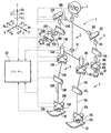
도 1은 본 발명의 실시형태에서의 다리식 이동 로봇의로서의 2족이동 로봇의 개략적인 구성을 도시하는 도면, BRIEF DESCRIPTION OF THE DRAWINGS The figure which shows schematic structure of the biped robot as the legged mobile robot in embodiment of this invention.
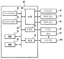
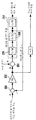
도 2는 도 1의 로봇에 구비한 제어 유닛의 구성을 도시하는 블럭도, 2 is a block diagram showing a configuration of a control unit included in the robot of FIG. 1;
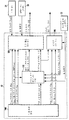
도 3은 도 2의 제어 유닛의 주요부의 기능적 구성을 도시하는 블럭도, 3 is a block diagram showing a functional configuration of a main part of the control unit of FIG. 2;
도 4는 실시형태에서의 로봇과 대상물과의 관계를 도시하는 도면, 4 is a diagram illustrating a relationship between a robot and an object in the embodiment;
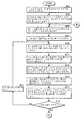
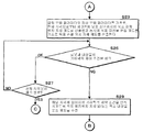
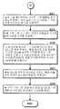
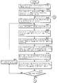
도 5는 제 1 실시형태에서의 보용 생성장치의 연산처리를 도시하는 플로우차트, 5 is a flowchart showing the arithmetic processing of the walk generating apparatus according to the first embodiment;
도 6은 제 1 실시형태에서의 보용 생성장치의 연산처리를 도시하는 플로우차트, 6 is a flowchart showing arithmetic processing of the walk generating apparatus according to the first embodiment;
도 7은 제 1 실시형태에서의 보용 생성장치의 연산처리를 도시하는 플로우차트, 7 is a flowchart showing the arithmetic processing of the walk generating apparatus according to the first embodiment;
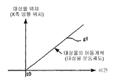
도 8은 도 5의 S02에서 결정하는 이동계획의 예를 도시하는 도면, FIG. 8 is a diagram showing an example of a movement plan determined in S02 of FIG. 5;
도 9는 도 5의 S02의 처리를 도시하는 블럭도, 9 is a block diagram showing a process of S02 in FIG. 5;
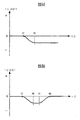
도 10(a)는 도 5의 S07에 관계되는 임시목표 ZMP 궤도의 예를 도시하는 도면, 도 10(b)는 도 5의 S17에서 결정되는 ZMP 수정량의 예를 도시하는 도면, 도 10(c)는 S17에서 수정된 목표 ZMP 궤도의 예를 도시하는 도면, FIG. 10A is a diagram showing an example of a temporary target ZMP trajectory related to S07 in FIG. 5, and FIG. 10B is a diagram showing an example of a ZMP correction amount determined at S17 in FIG. 5. c) is a diagram showing an example of a target ZMP trajectory modified in S17,
도 11은 도 5의 S11에서 결정하는 족평궤도 패러미터의 예를 도시하는 도면, FIG. 11 is a diagram showing an example of foot track parameters determined in S11 of FIG. 5;
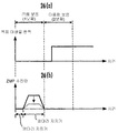
도 12(a)는 금회 보용의 대상물 상반력 모멘트 궤도의 예를 도시하는 도면, 도 12(b)은 도 5의 S11에서 결정하는 정상 보용의 대상물 반력 모멘트 궤도의 예를 도시하는 도면, 12 (a) is a diagram showing an example of the object upper reaction force moment trajectory for the current walk, and FIG. 12 (b) is a diagram showing an example of the object reaction force moment trajectory for the normal walk determined at S11 in FIG. 5;
도 13은 실시형태에서 사용하는 로봇 동역학 모델의 예를 도시하는 도면, 13 is a diagram illustrating an example of a robot dynamics model used in the embodiment;
도 14는 도 13의 로봇 동역학 모델을 사용하여 상체위치를 구하는 처리를 도시하는 블럭도, 14 is a block diagram showing a process for obtaining an upper body position using the robot dynamics model of FIG. 13;
도 15(a), (b)는 도 5의 S21의 처리를 설명하기 위한 도면, 15 (a) and 15 (b) are diagrams for explaining the processing of S21 in FIG. 5;
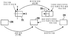
도 16은 도 6의 S29의 처리를 설명하기 위한 도면, FIG. 16 is a diagram for explaining a process of S29 of FIG. 6;
도 17은 도 7의 S35의 처리를 도시하는 블럭도, 17 is a block diagram showing the process of S35 in FIG. 7;
도 18(a), (b)는 도 5의 S01의 이동계획의 수정처리를 설명하기 위한 도면, 18 (a) and 18 (b) are diagrams for explaining the correction process of the movement plan of S01 in FIG. 5;
도 19는 도 3에 도시하는 대상물 반력 평형제어장치의 처리를 도시하는 블럭도, 19 is a block diagram showing a process of the object reaction force balance control device shown in FIG. 3;
도 20은 본 발명의 제 2 실시형태에서의 보용 생성장치의 주요부의 처리를 도시하는 플로우차트, 20 is a flowchart showing processing of main parts of the walk generating apparatus according to the second embodiment of the present invention;
도 21은 도 20의 S29'의 처리를 설명하기 위한 도면, 21 is a view for explaining a process of S29 'of FIG. 20;
도 22는 본 발명의 제 3 실시형태에서의 S03(도 5)의 처리를 도시하는 블럭도, Fig. 22 is a block diagram showing the process of S03 (Fig. 5) in the third embodiment of the present invention;
도 23은 본 발명의 제 4 실시형태에서의 S01(도 5)의 이동계획의 수정처리를 설명하기 위한 도면, Fig. 23 is a view for explaining the correction process of the movement plan of S01 (Fig. 5) in the fourth embodiment of the present invention;
도 24는 본 발명의 제 5 실시형태에서의 보용 생성장치의 주요부의 처리를 도시하는 플로우차트, 24 is a flowchart showing processing of main parts of the walk generating apparatus according to the fifth embodiment of the present invention;
도 25는 도 24의 S21'의 처리를 설명하기 위한 도면, 25 is a view for explaining a process of S21 'of FIG. 24;
도 26(a), (b)는 도 24의 S21'의 처리를 설명하기 위한 도면이다. 26 (a) and 26 (b) are diagrams for explaining the process of S21 'in FIG.
발명을 실시하기Carrying out the invention 위한 for 최량의Best 형태 shape
이하, 첨부된 도면을 참조하여 본 발명의 실시형태에 따른 다리식 이동 로봇의 보용 생성장치를 설명한다. 또한, 다리식 이동 로봇으로서는 2족이동 로봇을 예로 든다. Hereinafter, a walk generation apparatus for a legged mobile robot according to an embodiment of the present invention will be described with reference to the accompanying drawings. In addition, a biped robot is mentioned as a legged mobile robot.
도 1은 이 실시형태에 따른 다리식 이동 로봇으로서의 2족이동 로봇을 전체적으로 도시하는 개략도이다. Fig. 1 is a schematic diagram showing the biped robot as a legged mobile robot according to this embodiment as a whole.
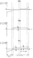
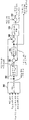
도시한 바와 같이, 2족이동 로봇(이하, 로봇이라고 함)(1)은 상체(로봇(1)의 기체)(3)로부터 하방으로 연장하여 설치된 좌우 한쌍의 다리체(다리부 링크)(2, 2)를 구비한다. 양다리체(2, 2)는 동일 구조이며, 각각 6개의 관절을 구비한다. 그 6개의 관절은 상체(3)측으로부터 차례로, 가랑이(股)(허리부)의 회선(回旋)(회전)용(상체(3)에 대한 요잉 방향의 회전용)의 관절(10R, 10L)(부호 R, L은 각각 우측 다리체, 좌측 다리체에 대응하는 것을 의미하는 부호이다. 이하 동일)과, 가랑이(허리부)의 롤링 방향(X축 주위)의 회전용의 관절(12R, 12L)과, 가랑이(허리부)의 피칭 방향(Y축 주위)의 회전용의 관절(14R, 14L)과, 무릎부의 피칭 방향의 회전용의 관절(16R, 16L)과, 발목의 피칭 방향의 회전용의 관절(18R, 18L)과, 발목의 롤링 방향의 회전용의 관절(20R, 20L)로 구성된다. As shown, a biped robot (hereinafter referred to as a robot) 1 is a pair of left and right legs (leg links) installed extending downward from the upper body (gas of the robot 1) 3. , 2). Both
각 다리체(2)의 발목의 2개의 관절 18R(L), 20R(L)의 하부에는, 각 다리체(2)의 선단부를 구성하는 족평(足平)(족부)22R(L)이 부착되어 붙어있고, 양다리체(2, 2)의 최상위에는, 각 다리체(2)의 가랑이의 3개의 관절 10R(L), 12R(L), 14R(L)을 통하여 상기 상체(3)가 부착되어 있다. 상체(3)의 내부에는, 상세를 후술하는 제어 유닛(60) 등이 격납된다. 또한, 도 1에서는 도시의 편의상, 제어 유닛(60)을 상체(3)의 외부에 기재하고 있다.
상기 구성의 각 다리체(2)에서는, 고관절(또는 허리관절)은 관절 10R(L), 12R(L), 14R(L)로 구성되고, 무릎관절은 관절 16R(L)로 구성되고, 발목관절은 관절 18R(L), 20R(L)로 구성된다. 또 고관절과 무릎관절은 대퇴 링크 24R(L)로 연결되고, 무릎관절과 발목관절은 하퇴 링크 26R(L)로 연결된다. In each
상체(3)의 상부의 양측부에는 좌우 한쌍의 팔체(팔 링크)(5, 5)가 부착됨과 동시에, 상체(3)의 상단부에는 머리부(4)가 배치된다. 양팔체(5, 5)는 동일 구조이고, 각각 7개의 관절을 구비한다. 즉, 각 팔체(5)는, 3개의 관절 30R(L), 32R(L), 34R(L)로 구성된 견관절과, 1개의 관절 36R(L)로 구성된 주관절과, 3개의 관절 38R(L), 40R(L), 42R(L)로 구성된 손목관절과, 이 손목관절에 연결된 손끝부(핸드) 44R(L)을 구비하고 있다. 또한, 머리부(4)는 본 발명의 요지와 직접적인 관련을 갖지 않기 때문에 상세한 설명을 생략한다. A pair of left and right arms (arm links) 5 and 5 are attached to both sides of the upper part of the
상기의 구성에 의해, 각 다리체(2)의 족평 22R(L)은 상체(3)에 대해 6개의 자유도가 주어져 있다. 그리고, 로봇(1)의 보행 등의 이동 중에, 양다리체(2, 2)를 합쳐서 6*2=12개(본 명세서에서 「*」는 스칼라에 대한 연산으로서는 승산을, 벡터에 대한 연산으로서는 외적을 나타냄)의 관절을 적당한 각도로 구동함으로써 양 족평(22R, 22L)의 원하는 운동을 행할 수 있다. 이것에 의해, 로봇(1)은 임의로 3차원 공간을 이동할 수 있다. 또, 각 팔체(5)는 상체(3)에 대해 7개의 자유도가 주어지고, 양팔체(5, 5)를 합쳐서 7*2=14개의 관절을 적당한 각도로 구동함으로써 후술하는 대차를 미는 등의 원하는 작업을 행할 수 있다. By the above structure, six degrees of freedom with respect to the
도 1에 도시하는 바와 같이, 각 다리체(2)의 발목관절 18R(L), 20R(L)의 하방에는 족평 22R(L)과의 사이에 공지의 6축력센서(50)가 개재되어 있다. 이 6축력센서(50)는, 각 다리체(2)의 족평 22R(L)의 착지의 유무, 및 각 다리체(2)에 작용하는 상반력(접지 하중) 등을 검출하기 위한 것이며, 이 상반력의 병진력의 3방향 성분(Fx, Fy, Fz) 및 모멘트의 3방향 성분(Mx, My, Mz)의 검출신호를 제어 유 닛(60)에 출력한다. 이 6축력센서(50)와 동일한 6축력센서(52)가, 각 팔체(5)의 손끝부(핸드) 44R(L)과 손목 관절 38R(L), 40R(L), 42R(L)과의 사이에 개재되고, 손끝부 44R(L)에 작용하는 외력의 병진력의 3방향 성분 및 모멘트의 3방향 성분의 검출신호가 이 6축력센서(52)로부터 제어 유닛(60)에 출력된다. 또, 상체(3)에는, Z축(연직방향(중력방향))에 대한 상체(3)의 경사각 및 그 각속도, 및 Z축 주위의 상체(3)의 회전각(요잉각) 및 그 각속도를 검출하기 위한 자세 센서(54)가 구비되고, 그 검출신호가 이 자세 센서(54)로부터 제어 유닛(60)에 출력된다. 이 자세 센서(54)는, 도시를 생략하는 3축방향의 가속도 센서 및 3축방향의 자이로 센서를 구비하고, 이들 센서의 검출신호가 상체(3)의 자세각(경사각 및 요잉각) 및 그 각속도를 검출하기 위해서 사용됨과 동시에, 로봇(1)의 자기 위치 자세를 추정하기 위해서 사용된다. 또, 상세구조의 도시는 생략하지만, 로봇(1)의 각 관절에는, 그것을 구동하기 위한 전동 모터(64)(도 2 참조)와, 그 전동 모터(64)의 회전량(각 관절의 회전각)을 검출하기 위한 인코더(로터리 인코더)(65)(도 2 참조)가 설치되고, 이 인코더(65)의 검출신호가 이 인코더(65)로부터 제어 유닛(60)에 출력된다. As shown in FIG. 1, the well-known 6-
또한, 도시는 생략하지만, 각 족평 22R(L)과 6축력센서(50) 사이에는, 스프링 등의 탄성체가 개재되고, 또한 족평 22R(L)의 밑바닥면에는, 고무 등의 탄성체가 붙여져 있다. 이들 탄성체는, 컴플라이언스 기구를 구성하는 것으로, 각 다리체(2)가 상반력을 받았을 때에 탄성변형하게 되어 있다. Although not shown, an elastic body such as a spring is interposed between each foot flat 22R (L) and the six-
도 2는 제어 유닛(60)의 구성을 도시하는 블럭도이다. 이 제어 유닛(60)은 마이크로컴퓨터에 의해 구성되어 있고, CPU로 이루어지는 제 1 연산장치(90) 및 제 2 연산장치(92), A/D변환기(80), 카운터(86), D/A변환기(96), RAM(84), ROM(94), 및 이것들 사이의 데이터 수수를 행하는 버스 라인(82)을 구비하고 있다. 이 제어 유닛(60)에서는, 각 다리체(2)의 6축력센서(50), 각 팔체(5)의 6축력센서(52), 자세 센서(54)(가속도 센서 및 레이트 자이로 센서) 등의 출력신호는 A/D변환기(80)에서 디지털값으로 변환된 후, 버스 라인(82)을 통하여 RAM(84)에 보내진다. 또 로봇(1)의 각 관절의 인코더(65)(로터리 인코더)의 출력은 카운터(86)를 통하여 RAM(84)에 입력된다. 2 is a block diagram showing the configuration of the
상기 제 1 연산장치(90)는 후술과 같이 목표 보용을 생성함과 동시에, 관절 각변위 지령(각 관절의 변위각 혹은 각 전동 모터(64)의 회전각의 지령값)을 산출하고, RAM(84)에 송출한다. 또, 제 2 연산장치(92)는 RAM(84)으로부터 관절 각변위 지령과, 상기 인코더(65)의 출력신호에 기초하여 검출된 관절각의 실측값을 읽어 내고, 각 관절의 구동에 필요한 조작량을 산출하여 D/A변환기(96)와 서보 앰프(64a)를 통하여 각 관절을 구동하는 전동 모터(64)에 출력한다. As described later, the
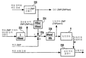
도 3은, 본 명세서의 실시형태에 따른 다리식 이동 로봇의 제어장치의 기능적 구성을 전체적으로 도시하는 블럭도이다. 이 도 3 중의 파선으로 둘러싼 부분이 제어 유닛(60)이 실행하는 처리기능(주로 제 1 연산장치(90) 및 제 2 연산장치(92)의 기능)에 의해 구성되는 것이다. 또한, 이하의 설명에서는, 다리체(2) 및 팔체(5)의 좌우를 특별히 구별할 필요가 없을 때는, 상기 부호 R, L을 생략한다. 3 is a block diagram generally showing a functional configuration of a control device of a legged mobile robot according to an embodiment of the present specification. The part enclosed by the broken line in this FIG. 3 is comprised by the processing function (mainly the function of the 1st
이하 설명하면 제어 유닛(60)의 기능적 구성은, 보용 생성장치(100), 대상물 반력 평형 제어장치(102), 다리 메인 제어장치(104) 및 팔 메인 제어장치(106)로 구성되어 있다. 이 명세서의 실시형태에서는, 보용 생성장치(100)의 처리를 제외하고, 대상물 반력 평형 제어장치(102), 다리 메인 제어장치(104) 및 팔 메인 제어장치(106)의 처리는, 본원 출원인이 앞서 일본 특개평10-230485호 공보(상기 특허문헌 1)에서 제안한 것과 동일하다. 따라서, 이하의 본 실시형태의 설명에서는, 보용 생성장치(100)를 중심으로 설명하고, 대상물 반력 평형 제어장치(102), 다리 메인 제어장치(104) 및 팔 메인 제어장치(106)의 설명은 개략적인 설명에 그친다. In the following description, the functional configuration of the
보용 생성장치(100)는 로봇(1)의 목표 보용을 자유롭고 또한 리얼타임으로 생성하여 출력하는 것으로, 본원 발명의 보용 생성장치에 상당하는 것이다. 이 보용 생성장치(100)가 출력하는 목표 보용은 목표 상체위치 자세궤도(상체(3)의 목표 위치 궤도 및 목표 자세궤도), 목표 족평위치 자세궤도(각 족평(22)의 목표 위치 궤도 및 목표 자세궤도), 목표 손끝위치 자세궤도(각 팔체(5)의 손끝부(44)의 목표 위치 궤도 및 목표 자세궤도), 목표 전체 상반력 중심점 궤도(전체 상반력 중심점의 목표 위치의 궤도), 목표 전체 상반력 궤도, 및 목표 대상물 반력 궤도로 구성된다. 또한, 다리체(2)나 팔체(5) 이외에 상체(3)에 대해 가동인 부위를 구비하는 경우에는, 그 가동 부위의 목표 위치 자세궤도가 목표 보용에 더해진다. 이하의 설명에서는, 오해를 일으킬 우려가 없는 경우에는, 종종 「목표」를 생략한다. The
여기에서, 보용 생성장치(100)가 생성하는 목표 보용에 관계되는 용어의 의미 및 정의에 대해 설명해 둔다. 보용에서의 「궤도」는 시간적 변화의 패턴(시계열 패턴)을 의미한다. Here, the meanings and definitions of terms related to the target walks generated by the
족평위치, 상체위치 등, 로봇(1)의 각 부위의 「위치」는 그 부위에 고정적 으로 설정된 어떤 대표점의 위치를 의미한다. 예를 들면, 본 실시형태에서는, 각 족평(22)의 대표점은, 그 족평(22)을 구비하는 다리체(2)의 발목관절의 중심으로부터, 이 족평(22)의 밑바닥면에 연장시킨 수선이 이 밑바닥면과 교차하는 점으로, 그 대표점의 위치가 족평위치이다. 또, 「자세」는 공간적인 방향을 의미한다. 구체적으로는, 예를 들면 상체자세는 Z축(연직축)에 대한 롤링 방향(X축 주위)의 상체(3)의 경사각과 피칭 방향(Y축 주위)의 상체(3)의 경사각과 요잉 방향(Z축 주위)의 상체(3)의 회전각(요잉각)으로 표시되고, 족평자세는 각 족평(22)에 고정적으로 설정된 2축의 공간적인 방위각으로 표시된다. The "position" of each part of the
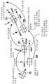
또한, 보용 중의 상반력 및 대상물 반력에 관계되는 구성요소 이외의 구성요소, 즉 족평위치 자세, 상체위치 자세 등, 로봇(1)의 운동에 관계되는 보용을 총칭적으로 「운동」이라고 한다. 또, 운동의 궤도는, 일정(시간적으로 변화되지 않음) 또는 거의 일정한 것이어도 된다. 예를 들면 로봇(1)이 그 양 족평(22, 22)을 착지시킨 상태로 유지하여, 이동하지 않는 상태에서는, 족평위치 자세궤도는 일정하게 된다. In addition, walks related to the movement of the
보용 중의 대상물 반력은, 로봇(1)에게 어떤 대상물을 이동시킬 때에 이 대상물에 로봇(1)으로부터 작용시키는 힘의 반력(대상물로부터 로봇(1)에 작용하는 힘)을 의미한다. 따라서, 목표 대상물 반력 궤도는 본 발명에서의 로봇대상물 간 목표 작용력의 궤도에 상당한다. 본 명세서의 실시형태에서는, 예를 들면 도 4에 도시하는 바와 같이, 로봇(1)이 어떤 대상물(120)(도시한 예에서는 대차)의 소정의 위치에 양팔체(5, 5)의 손끝부(44R, 44L) 걸어맞추어지게 한 상태에서 보행 동작을 행하면서 이 대상물(120)을 미는 작업을 행하는 경우를 예로 들어 설명한다. 이 대상물(120)로부터 로봇(1)이 받는 힘이 대상물 반력이다. 대상물 반력은, 일반적으로, 병진력 성분과 모멘트 성분으로 구성된다. 단, 본 명세서의 본 실시형태에서는, 대상물 반력은 로봇(1)에 대상물(120)로부터 작용하는 병진력을 의미하는 것으로 하고, 그 병진력에 의해 로봇(1)에 작용하는, 어떤 점 주위의 모멘트를 대상물 반력 모멘트라고 한다. 보충하면, 대상물 반력은 로봇(1)으로부터 대상물(120)에의 작용력을 대상물 반력 대신 사용해도 된다. The object reaction force during walking means the reaction force (force acting on the
또한, 본 명세서에서는, 대상물(120)의 운동에 관하여, 대상물(120)의 위치는 로봇(1)의 족평위치 등과 동일하게, 대상물(120)에 고정적으로 설정된 대표점의 위치를 의미한다. 또, 대상물(120)의 자세는 로봇(1)의 족평(22)의 자세 등과 동일하게, 대상물(120)의 공간적인 방향을 의미한다. 그리고, 대상물(120)의 위치 및 자세를 총칭적으로 대상물 운동이라고 하기도 한다. In addition, in the present specification, with respect to the movement of the object 120, the position of the object 120 means the position of the representative point fixedly set to the object 120, such as the foot position of the robot (1). In addition, the posture of the object 120 means the spatial direction of the object 120, in the same manner as the posture of the foot flat 22 of the
또, 각 족평(22)이 작용하는 상반력(병진력 및 모멘트로 이루어지는 상반력)을 「각 족평 상반력」이라고 부르고, 로봇(1)의 모든(2개) 족평(22R, 22L)에 대한 「각 족평 상반력」의 합력을 「전체 상반력」이라고 한다. 단, 이하의 설명에서는, 각 족평 상반력은 거의 언급하지 않으므로, 특별히 예고하지 않는 한, 「상반력」은 「전체 상반력」과 동의로서 취급한다. In addition, the normal reaction force (the normal force consisting of a translation force and a moment) which each foot flat 22 acts is called "each foot flat reaction force", and is referred to the all (two)
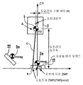
목표 상반력은, 일반적으로는, 작용점과 그 점에 작용하는 병진력 및 모멘트에 의해 표현된다. 작용점은 어디에 두어도 좋으므로, 동일한 목표 상반력에서도 무수한 표현을 생각할 수 있지만, 특히 목표 상반력 중심점(전체 상반력의 중심점 의 목표 위치)을 작용점으로 하여 목표 상반력을 표현하면, 목표 상반력의 모멘트 성분은 연직성분(연직축(Z축) 주위의 모멘트)을 제외하고 0이 된다. 바꾸어 말하면, 목표 상반력 중심점 주위의 목표 상반력의 모멘트의 수평성분(수평축(X축 및 Y축) 주위의 모멘트)은 0이 된다. 그래서, 본 명세서의 본 실시형태에서는, 목표 상반력 중심점을 목표 전체 상반력의 작용점으로 하여, 보용 생성장치(100)에서 생성하는 것으로 했다. 또한, 목표 상반력 중심점은, 목표 전체 상반력의 작용점으로서의 의미를 갖는 것이기 때문에, 본질적으로는 목표 전체 상반력의 1개의 구성요소라고 할 수 있다. 단, 본 실시형태에서는, 목표 상반력 중의 목표 상반력 중심점이 본 발명과 밀접하게 관련되는 것이므로, 도 3에서는, 목표 전체 상반력 중의 작용점인 목표 상반력 중심점을 목표 전체 상반력과는 별도로 기재하는 것으로 했다. The target reaction force is generally expressed by the point of action and the translational force and moment acting on the point. Since the working point may be placed anywhere, numerous expressions can be conceived even at the same target reaction force. However, when the target reaction force is expressed using the target reaction force center point (the target position of the center point of the overall reaction force), the moment of the target reaction force The component is zero except for the vertical component (the moment around the vertical axis (Z axis)). In other words, the horizontal component (the moment around the horizontal axis (X-axis and Y-axis)) of the moment of the target phase reaction force around the target normal force center point becomes zero. Therefore, in this embodiment of this specification, it is assumed that the
또, 본 명세서에서는, ZMP(zero moment point)는 로봇의 운동에 의해 발생하는 관성력과 이 로봇에 작용하는 중력과 대상물 반력과의 합력(또는 그 합력과 균형을 이루는 상반력)이 그 점 주위에 작용하는 모멘트가, 연직성분을 제외하고 0이 되는 점의 의미로 사용한다. 동역학적 평형조건을 만족하는 보용에서는, 로봇의 목표 운동궤도와 중력과 목표 대상물 반력으로부터 산출되는 ZMP와 목표 상반력 중심점은 일치한다. 본 명세서에서는, 대부분의 경우, 목표 상반력 중심점 대신에, 목표 ZMP라고 한다. In addition, in this specification, ZMP (zero moment point) is the inertia force generated by the movement of a robot, and the force (or normal reaction force which balances with that force) of gravity and object reaction force acting on this robot. The acting moment is used to mean that the point becomes zero except for the vertical component. In gait that satisfies the dynamic equilibrium conditions, the ZMP calculated from the robot's target trajectory and gravity and the target object reaction force coincide with the target center of reaction force. In this specification, in most cases, the target ZMP is referred to as the target ZMP instead of the target reaction force center point.
또, 본 명세서에서는, 목표 보용은 소정 기간분의 목표 운동과 목표 상반력(목표 ZMP를 포함함)과 목표 대상물 반력과의 세트를 의미하는 것으로 한다. 특 히, 본 실시형태에서는, 목표 보용(간단히 보용이라고 칭한 경우를 포함함)은, 예고하지 않는 한, 로봇(1)의 1보의 기간분의 목표 운동과 목표 상반력(목표 ZMP를 포함함)과 목표 대상물 반력과의 세트를 의미하는 것으로 한다. 이 경우, 목표 보용의 「1보」는, 로봇(1)의 한쪽 다리체(2)가 착지하고나서, 다른 한쪽 다리체(2)가 착지할 때까지의 의미로 사용한다. 또한, 일련의 보용은 몇개의 보용(소정 기간분의 보용)이 연결된 것으로 한다. 또, 이후의 설명에서는, 1보의 기간분의 목표 보용을 단위 보용이라고 하는 경우가 있다. 또, 로봇(1)이 이동하지 않는 상태(양 족평(22, 22)의 접지를 유지하는 상태)에서의 1보의 기간은 어떤 소정의 기간(로봇(1)이 이동하는 경우의 1보의 기간에 상당하는 기간)을 의미한다. In addition, in this specification, a target maintenance shall mean the set of the target exercise for a predetermined period, and a target reaction force (including target ZMP), and a target object reaction force. In particular, in the present embodiment, the target gait (including the case of simply called gait) includes the target motion and the target reaction force (target ZMP) for the period of 1 step of the
또, 보용에 있어서의 양다리 지지기란, 로봇(1)이 그 자중을 양다리체(2, 2)로 지지하는 기간(양다리체(2, 2)가 지지다리가 되는 기간), 한쪽다리 지지기란 어느 한쪽 다리체(2)로 로봇(1)의 자중을 지지하는 기간(한쪽만의 다리체(2)가 지지다리가 되는 기간)을 말한다. 본 실시형태에서의 목표 보용(단위 보용)은, 달리 말하면, 양다리 지지기의 개시 시로부터 다음 한쪽다리 지지기의 종료 시까지의 기간분의 목표 보용이다. 로봇(1)의 자중을 지지하는 다리체(2)를 지지다리라고 부른다. 양다리 지지기에서는, 양다리체(2, 2)가 지지다리가 되고, 한쪽다리 지지기에서는 1개의 다리체(2)가 지지다리가 된다. 또, 한쪽다리 지지기에서 로봇(1)의 자중을 지지하지 않는 측의 다리체(2)(지지다리가 아닌 다리체(2))를 미착지다리라고 부른다. 또한, 이후의 설명에서는, 특별히 예고하지 않는 한, 목표 보용에서의 지지다리는, 양다리 지지기의 개시 시에 착지하는 다리체(2)(이 양다리 지지기에 계속되는 한쪽다리 지지기에서 지지다리가 되는 다리체(2))를 의미하는 것으로 한다. 또, 지지다리측의 다리체(2)의 족평(22), 미착지다리측의 다리체(2)의 족평(22)을 각각 지지다리 족평(22), 미착지다리 족평(22)이라고 한다. 또, 로봇(1)이 이동하지 않은 상태(양족평(22,22)의 접지를 유지하는 상태)이어도, 일방의 다리체(2)가 지지다리, 타방의 다리체(2)가 미착지 다리인 것으로 한다. In addition, with both-leg support in gait, the period in which the
또, 보용 생성장치(100)에 의해 새롭게 생성하려고 하고 있는 목표 보용(단위보용), 또는 생성하고 있는 목표 보용(단위 보용)을 금회 보용이라고 부르고, 이 금회 보용의 1보전의 목표 보용을 전회 보용, 금회 보용의 다음 1보의 목표 보용을 다음회 보용, 더욱 그 다음 1보의 목표 보용을 다음다음회 보용 등으로 부른다. In addition, the target gait (unit gait) that is about to be newly generated by the
또한, 목표 보용은 글로벌 좌표계로서의 지지다리 좌표계로 기술된다. 본 실시형태에서는, 지지다리 좌표계는, 지지다리 족평(22)을 수평자세(보다 일반적으로는 바닥면에 평행한 자세)로 하고 이 지지다리 족평(22)의 밑바닥면의 거의 전체면을 바닥면에 접촉(밀착)시킨 상태에서, 이 지지다리의 발목관절(18, 20)의 중심으로부터 바닥면에 연장시킨 수선이 이 바닥면과 교차하는 점(이 점은, 본 명세서의 실시형태의 예에서는 지지다리 족평(22)의 밑바닥면의 거의 전체면을 바닥면에 접촉시킨 상태에서는, 이 족평(22)의 대표점과 일치함)을 원점으로 하고, 그 원점을 지나는 수평면을 XY평면으로 하는 글로벌 좌표계(바닥에 고정된 좌표계)이다. 이 경우, X축 방향, Y축 방향은 각각 지지다리 족평(22)의 전후 방향, 좌우측 방향이다. 이후의 설명에서는, X축, Y축, Z축은, 특별히 예고하지 않는 한, 이 지지다리 좌표계의 3축을 의미하는 것으로 한다. 또한, 지지다리 좌표계의 원점은, 반드 시 지지다리 족평(22)의 밑바닥면의 거의 전체면을 바닥면에 접촉시킨 상태에서의 이 족평(22)의 대표점에 일치할 필요는 없고, 이 대표점과 상이한 바닥면상의 점에 설정되어도 된다. The target gait is also described in the support leg coordinate system as a global coordinate system. In the present embodiment, the support leg coordinate system has the support leg foot flat 22 in a horizontal posture (more generally, a posture parallel to the floor surface), and almost the entire bottom surface of the support leg foot flat 22 is the bottom face. In the state in which it is in contact with (contact with) the point where the waterline extending from the center of the ankle joints 18 and 20 of this support leg to the bottom surface intersects the bottom surface. In the state where almost the entire bottom surface of the support leg foot flat 22 is in contact with the bottom surface, the origin is set as the origin and the horizontal plane passing through the origin is the XY plane. Coordinate system (coordinate fixed to the floor). In this case, the X-axis direction and the Y-axis direction are the front-back direction and the left-right direction of the support leg foot flat 22, respectively. In the following description, the X-axis, Y-axis, and Z-axis mean three axes of this support leg coordinate system, unless otherwise noted. In addition, the origin of the support leg coordinate system does not necessarily need to coincide with the representative point of the foot flat 22 in a state where almost the entire bottom surface of the support leg foot flat 22 is in contact with the bottom surface. You may be set to the point on the bottom surface different from a point.
이상에서 설명한 사항은, 이하에 설명하는 제 1 실시형태에 한하지 않고, 본 명세서에서 설명하는 각 실시형태에서 공통의 사항이다. The matters described above are not limited to the first embodiment described below, but are common to each embodiment described herein.
[제 1 실시형태][First embodiment]
이하에 본 발명의 제 1 실시형태에 따른 보용 생성장치(100)의 상세를 설명한다. 도 5~도 7은 보용 생성장치(100)의 처리를 나타내는 플로우차트이다. 또한, 이 제 1 실시형태는, 본 발명의 제 1 발명, 제 2 발명, 및 제 4 발명의 실시형태이다. 보용 생성장치(100)는 그 연산처리기능에 의해, 본 발명의 제 1 발명에서의 모델 조작량 결정 수단, 로봇?대상물 간 작용력 궤도 임시결정 수단, 대상물 운동궤도 임시결정 수단, 로봇 보용 임시생성 수단, 제약조건 판단 수단, 수정 수단을 구성하고 있다. The details of the
보용 생성장치(100)는 도 5~도 7의 플로우차트에 나타내는 처리를 소정의 연산처리 주기로 차례차례 실행한다. The
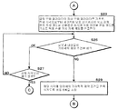
우선, S01에서, 대상물(120)의 이동계획이 결정된다. 여기에서 결정되는 이동계획은 적어도 현재 시각으로부터 장래의 소정 기간분(로봇(1)의 복수보분)의 대상물(120)의 이동계획을 포함하고 있다. 이 이동계획은, 기본적으로는 대상물(120)의 이동 요구(대상물(120)을 어떤 타이밍으로 어떻게 움직일 것인가라고 하는 설계적인 요구)에 따라 결정되고, 이 대상물(120)의 위치 자세궤도(위치 및 자 세의 시계열), 또는, 그 궤도를 규정하는 패러미터 혹은 함수식 등으로 구성된다. 예를 들면 대상물(120)의 이동 요구가, 어떤 시각 t0로부터 X축 방향으로 일정 속도로 대상물(120)을 이동시킨다고 하는 요구인 경우에는, 이동계획은 도 8의 그래프 g1으로 나타내는 바와 같이 결정된다. 그래프 g1은, 이동계획에서의 대상물 위치(X축방향 위치)의 경시 변화를 나타내고 있다. 이 경우, 예를 들면 현재 시각 이후의 각 시각(어떤 일정한 시간간격마다의 시각)에서의 대상물(120)의 위치의 시계열을 이동계획으로서 결정해도 되지만, 시각 t0와 그래프 g1의 기울기(대상물(120)의 이동속도)를 이동계획을 규정하는 요소(패러미터)로서 결정하거나, 또는 그래프 g1의 함수식을 이동계획을 규정하는 요소(패러미터)로서 결정해도 된다. 또한, 이동요구는 보용 생성장치(100)에 외부로부터 적당하게 주어지거나, 또는, 미리 제어 유닛(60)의 도시하지 않은 기억수단에 기억 유지된다. First, in S01, the movement plan of the object 120 is determined. The movement plan determined here includes a movement plan of the target object 120 for a predetermined period (multiple complementary portions of the robot 1) at least from the current time. This movement plan is basically determined according to the movement request of the object 120 (design demanding how to move the object 120 at what timing) and the position attitude track of the object 120 (position and Time series), or a parameter or function that defines its trajectory. For example, when the movement request of the object 120 is a request to move the object 120 at a constant speed in the X-axis direction from a certain time t0, the movement plan is determined as shown by the graph g1 of FIG. . The graph g1 has shown the time-dependent change of the object position (X-axis direction position) in a movement plan. In this case, for example, the time series of the position of the object 120 at each time after the current time (time at any given time interval) may be determined as the movement plan, but the time t0 and the slope of the graph g1 (object 120 ) May be determined as an element (parameter) that defines the movement plan, or the function expression of graph g1 may be determined as an element (parameter) that defines the movement plan. Further, the movement request is appropriately given to the
보충하면, S01에서 결정하는 이동계획은, 반드시 이동요구대로 결정되는 것은 아니고, 필요에 따라 적당하게 수정되지만, 이것에 대해서는 후술한다. Supplementally, the movement plan determined in S01 is not necessarily determined as the movement request, but is appropriately modified as necessary, but this will be described later.
다음에 S03으로 진행하고, 상기한 바와 같이 S01에서 결정된 이동계획을 기초로, 대상물 동역학 모델을 사용하여 목표 대상물 운동궤도(목표 대상물 위치 자세궤도)와, 목표 대상물 반력 궤도가 임시결정된다. Next, the process proceeds to S03, and based on the movement plan determined in S01, the target object motion trajectory (target object position attitude track) and the target object reaction force trajectory are temporarily determined using the object dynamics model.
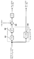
여기에서, 이 S03의 처리와, 이 처리에서 사용하는 대상물 동역학 모델을 도 9의 블럭도를 참조하여 설명한다. 도 9는, S03에서 목표 대상물 운동궤도 중의 목표 대상물 위치 궤도와, 목표 대상물 반력 궤도를 구하는 연산처리를 나타내는 블럭도이다. 이 블럭도 중의 파선으로 둘러싼 부분이 대상물(120)에 작용하는 힘과 대상물(120)의 운동과의 관계를 나타내는 대상물 동역학 모델로 되어 있다. 또한, 본 실시형태에서는, 이해의 편의상, 대상물(120)을 거의 수평한 바닥 상에서 이동시키는 경우를 예로 들어서 설명한다. Here, the processing of S03 and the object dynamics model used in this processing will be described with reference to the block diagram of FIG. FIG. 9 is a block diagram showing arithmetic processing for determining a target object position trajectory and a target object reaction force trajectory in the target object motion trajectory in S03. The part enclosed by the broken line in this block diagram becomes the object dynamics model which shows the relationship between the force which acts on the object 120, and the motion of the object 120. FIG. In addition, in this embodiment, the case where the object 120 is moved on a substantially horizontal bottom is demonstrated as an example for convenience of understanding.
도 9에 도시하는 대상물 동역학 모델은, 본 발명의 제 1 발명에서의 대상물 동력학 모델에 상당하고 있고, 대상물(120)에 작용시키는 힘(보다 상세하게는 수평방향의 병진력)을 입력으로 하고, 대상물(120)의 위치를 출력하는 동력학 모델(순동력학 모델)이다. 보다 상세하게는, 이 대상물 동역학 모델은 대상물(120)에 작용시키는 수평방향의 병진력의 입력값(후술의 가산부(204)에서 구해지는 값)에, 대상물(120)의 질량(M)의 역수 1/M을 승산부(206)에서 승산함으로써 대상물(120)의 운동가속도를 구하고, 이것을 적분기(208, 210)로 차례로 적분(2중 적분)함으로써 대상물(120)의 위치(대상물 동역학 모델 상에서의 위치)를 출력하는 것으로 되어 있다. 즉, 본 실시형태에서는, 도 9에 도시하는 대상물 동역학 모델은, 대상물(120)에 작용하는 병진력이 대상물(120)의 가속도와 질량의 적과 동일하다고 하는 운동방정식을 기초로 구성되어 있다. 또한, 적분기(208)의 출력은 대상물 동역학 모델 상에서의 대상물(120)의 이동속도를 의미하고 있고, 이하, 이것을 대상물 모델 속도라고 한다.The object dynamics model shown in FIG. 9 corresponds to the object dynamics model in the first invention of the present invention, and inputs a force (more specifically, a translational force in the horizontal direction) applied to the object 120. It is a kinetic model (pure dynamics model) that outputs the position of the object 120. In more detail, this object dynamics model is based on the input of the horizontal translation force acting on the object 120 (the value obtained by the
이러한 대상물 동역학 모델을 사용하는 S03의 연산처리를 도 9를 참조하여 구체적으로 설명한다. 우선, 상기 S01에서 결정된 이동계획에 기초하는 대상물(120)의 순시순시의(각 시각의) 목표 속도인 목표 대상물 속도와, 적분기(208)에서 먼저 구해진 대상물 모델 속도가 감산부(200)에 입력되고, 그것들의 편차(=목표 대상물 속도-대상물 모델 속도)가 구해진다. 여기에서, 목표 대상물 속도는, 이동계획에 있어서의 대상물(120)의 위치 궤도의 1차미분값으로서 얻어지는 값, 또는 이동계획의 구성요소이다. 또한, 상기 도 8에 도시한 이동계획의 예에서는, 그래프 g1의 기울기를 그대로 목표 대상물 속도로 하면 되고, 이 경우에는, 목표 대상물 속도는 계속적으로 일정값으로 된다. 그리고, 현재 시각으로부터 장래의 소정 기간분(로봇(1)의 복수보분)의 목표 대상물 속도의 시계열이 감산부(200)에 차례로 입력된다. 또, 감산부(200)에 입력되는 대상물 모델 속도는, 새롭게 입력하는 목표 대상물 속도의 하나 전의 목표 대상물 속도를 감산부(200)에 입력했을 때에 적분기(208)로부터 출력된 값이다. The calculation process of S03 using this object dynamics model will be described in detail with reference to FIG. First, the target object speed, which is the target speed of the instantaneous instantaneous (at each time) of the object 120 based on the movement plan determined in step S01, and the object model speed obtained first in the
이어서, 상기 편차에 소정의 게인(Kv)을 승산부(202)에서 승산함으로써, 대상물(120)에 로봇(1)으로부터 작용시킬 병진력의 요구값이 구해진다. 즉, 본 실시형태에서는, 이 병진력의 요구값은, 목표 대상물 속도와 대상물 모델 속도와의 편차가 0에 수렴하도록(대상물 모델 속도가 목표 대상물 속도에 추종하도록), 피드백제어칙에 의해 결정된다. 그 피드백제어칙으로서는, 이 예에서는 비례제어칙이 사용된다. 그리고, 구해진 병진력의 요구값의 부호를 반전시킨 것의 시계열이 목표 대상물 반력 궤도로서 출력된다. Subsequently, by multiplying the deviation by a predetermined gain Kv in the
또, 구해진 병진력의 요구값과, 실제의 대상물(120)에 로봇(1) 이외로부터 작용하는 외란력(바닥으로부터 대상물(120)에 작용하는 마찰력 등)의 추정값인 추정 외란력이 가산부(204)에 입력되고, 이 병진력의 요구값과 추정 외란력과의 합이, 상기 대상물 동역학 모델에 대한 병진력의 입력값으로서 가산부(204)에 의해 구해진다. 여기에서, 추정 외란력은 본 발명의 제 1 발명에서의 모델 조작량에 상당하고, 보용 생성장치(100)의 연산처리 주기마다 후술의 S35의 처리에서 구해지는 것이다. 가산부(120)에 입력하는 추정 외란력으로서는, 보용 생성장치(100)의 전회의 연산처리 주기에서 구해진 값(전회값)이 사용된다. 그리고, 이와 같이 구한 병진력의 입력값을 대상물 동역학 모델에 입력함으로써, 상기한 바와 같이 대상물(120)의 위치가 구해지고, 이 구한 위치의 시계열이 적분기(210)에서 목표 대상물 위치 궤도로서 출력된다. In addition, the estimated disturbance force which is the estimated value of the calculated translational force and the disturbance force (such as frictional force acting on the object 120 from the bottom) acting on the actual object 120 from the
또한, 대상물 동역학 모델의 적분기(208)의 출력의 초기값은, 보용 생성장치(100)의 전회의 연산처리 주기에서 S03의 처리를 실행하고 구한 대상물 모델 속도의 시계열 중의, 전회의 연산처리 주기에 대응하는 시각(전회의 연산처리 주기에서의 현재 시각)에서의 값에 설정된다. 또, 적분기(210)의 출력의 초기값은, 보용 생성장치(100)의 전회의 연산처리 주기에서 S03의 처리를 실행하여 구한 목표 대상물 위치의 시계열 중의, 전회의 연산처리 주기에 대응하는 시각(전회의 연산처리 주기에서의 현재 시각)에서의 값에 설정된다. In addition, the initial value of the output of the
또, 목표 대상물 운동궤도 중의 목표 대상물 자세궤도는, 예를 들면 목표 대상물 속도의 방향에 거의 일치하도록 결정된다. In addition, the target object attitude trajectory in the target object movement trajectory is determined so as to substantially match the direction of the target object velocity, for example.
보충하면, 이동계획 및 추정 외란력이 일정하게 유지되고 있는 한, 목표 대상물 운동궤도나 목표 대상물 반력 궤도는 일정하게 되므로, S03의 처리는, 반드시 보용 생성장치(100)의 연산처리 주기마다 행할 필요는 없다. 따라서, 예를 들면 S03의 처리는, 로봇(1)의 1보마다 또는 보용 생성장치(100)의 연산처리 주기의 복 수 주기마다 행하거나, S01에서 이동계획을 변경한 경우나, 추정 외란력이 비교적 크게 변화된 경우에 행하는 것으로 해도 된다. Supplementally, as long as the movement plan and the estimated disturbance force are kept constant, the target object motion trajectory and the target object reaction force trajectory are constant, so the process of S03 must be performed at every calculation processing cycle of the
이상에서 설명한 S03의 처리에 의해, 현재 시각으로부터 장래의 소정 기간분의 목표 대상물 운동궤도와 목표 대상물 반력 궤도가 임시결정된다. By the processing of S03 described above, the target object motion trajectory and the target object reaction force trajectory for a predetermined period from the present time are temporarily determined.
또한, 이 S03의 처리는, 본 발명의 제 1 발명에서의 로봇?대상물간 작용력 궤도 임시결정 수단 및 대산물 운동궤도 임시결정 수단에 상당하고 있다. 보다 상세하게는, 감산부(200) 및 승산부(202)에 의해, 이동계획에 기초하는 목표 대상물 속도(목표 운동상태량)에 대상물 동역학 모델 상에서의 대상물의 이동속도인 대상물 모델 속도를 추종시키도록 대상물(120)에 로봇(1)으로부터 작용시킬 병진력의 요구값을 구하고, 또, 이 요구값으로부터 목표 대상물 반력 궤도를 구하는(이 요구값의 부호를 반전시키는) 처리가 로봇?대상물 간 작용력 궤도 임시결정 수단의 처리에 상당하고 있다. 또, 가산부(204)와 대상물 동역학 모델의 승산부(206), 적분기(208, 210)의 처리가 대상물 운동 임시결정 수단의 처리에 상당하고 있다. The processing of S03 corresponds to the robot-object interworking force trajectory determination means and the product movement trajectory temporary determination means in the first aspect of the present invention. More specifically, the
이어서, S05로 진행하고, 상기한 바와 같이 임시결정된 목표 대상물 운동궤도를 기초로, 로봇(1)의 미착지다리 족평(22)의 착지 예정위치 자세 및 착지 예정시각이 임시결정된다. 여기에서 임시결정 하는 착지 예정위치 자세 및 착지 예정시각은, 현재, 작성하고자 하고 있는 목표 보용인 금회 보용에서의 미착지다리 족평(22)의 착지 예정위치 자세 및 착지 예정시각을 포함하는, 로봇(1)의 복수보분(적어도 2보분)의 미착지다리 족평(22)의 착지 예정위치 자세 및 착지 예정시각이다. 즉, 임시결정 하는 착지 예정위치 자세 및 착지 예정시각은, 적어도 금회 보 용의 미착지다리 족평(22)의 착지 예정위치 자세 및 착지 예정시각과, 다음회 보용의 미착지다리 족평(22)의 착지 예정위치 자세 및 착지 예정시각을 포함한다. 이 경우, 미착지다리 족평(22)의 착지 예정위치 자세 및 착지 예정시각은, S03에서 결정된 목표 대상물 운동궤도에 대해, 착지 예정시각에서의 미착지다리 족평(22)의 착지위치 자세가 그 시각에서의 대상물 위치 자세와 소정의 상대적 위치 자세 관계가 되도록 결정된다. Subsequently, the procedure proceeds to S05 and based on the target object motion trajectory temporarily determined as described above, the landing scheduled position posture and the landing scheduled time of the
단, 미착지다리 족평(22)의 착지 예정위치 자세 및 착지 예정시각은, 반드시 목표 대상물 위치 자세에 추종하는 형태로 결정할 필요는 없다. 예를 들면, 로봇(1)의 이동을 행하지 않는 상태(양족평(22, 22)의 접지를 유지하는 상태)에서, 대상물(120)을 밀어서 이동시키고, 그 이동개시 후는, 팔체(5, 5)의 손끝부(44)를 대상물(120)로부터 떼는 경우에는, 각 보용에서의 미착지다리 족평(22)의 착지 예정위치 자세는 경시적으로 일정하게 유지되게 된다. 즉, 일반적으로는, 미착지다리 족평(22)의 착지 예정위치 자세 및 착지 예정시각은, 목표 대상물 운동궤도뿐만 아니라, 로봇(1)의 어떠한 운동에 의해, 대상물(120)을 옮길 것인가라고 하는 설계적인 요구에 따라 결정된다. However, it is not necessary to determine the landing scheduled position posture and the landing scheduled time of the non-arrival leg foot flat 22 in the form that follows the target object position posture. For example, in a state where the
또한, 미착지다리 족평(22)의 착지예정 위치 자세는, 보다 상세하게는, 미착지다리 족평(22)의 발뒤꿈치를 착지하고나서, 이 미착지다리 족평(22)을 바닥에 접촉시킨 채, 미끄러지지 않도록 피칭 방향으로 회전시켜서 이 미착지다리 족평(22)의 밑바닥면의 거의 전체면을 바닥면에 접촉시킨 상태에서의 이 미착지다리 족평(22)의 위치 자세이다. 따라서, 본 실시형태에서는, 미착지다리 족평(22R 또는 22L)의 착지 예정위치 자세는, 그 착지 시부터 다음 미착지다리 족평(22L 또는 22R)의 착지까지의 단위 보용에 있어서의 지지다리 좌표계의 위치 자세를 규정하는 것이 되고, 미착지다리 족평(22)의 착지 예정위치 자세를 결정함으로써, 그것에 대응하여, 상기한 지지다리 좌표계의 설정수법에 따라 각 단위보용에서의 지지다리 좌표계의 위치 자세가 결정되게 된다. 구체적으로는, 각 단위보용에서의 지지다리 좌표계는, 이 단위보용의 하나 전의 단위 보용의 미착지다리 족평(22)을 그 착지예정 위치 자세에 일치시킨 상태에서, 이 족평(22)을 갖는 다리체(2)의 발목관절의 중심으로부터 바닥면에 연장시킨 수선이 이 바닥면과 교차하는 점을 원점으로 하는 좌표계가 된다. In addition, the estimated landing position of the non-established foot flat 22 is more specifically, after landing the heel of the non-established leg flat 22, with the non-established leg flat 22 being in contact with the floor. It is a positional posture of this
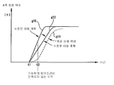
이어서, S07로 진행하고, 금회 보용의 목표 ZMP 궤도를 규정하는 ZMP 궤도 패러미터가 임시결정된다. 여기에서 임시결정되는 ZMP 궤도 패러미터는, 그것에 의해 규정되는 금회 보용의 목표 ZMP(이하, 임시목표 ZMP라고 함)가, S05에서 임시결정된 착지 예정위치 자세 및 착지 예정시각에 의해 정해지는, 금회 보용에서의 지지다리 족평(22)의 접지면(양다리 지지기에서는, 양족평(22)의 접지면을 포함하는, 소위 지지다각형)의 거의 중앙 부근에 존재하고, 또한, 급격한 변화를 하지 않도록 결정된다. 즉, 금회 보용의 임시목표 ZMP가, 로봇(1)의 접지면 내(또는 지지다각형 내)의, 로봇(1)의 안정여유가 가능한 한 높아지는 위치에 존재하고, 또한, 급격한 변화를 하지 않도록 ZMP 궤도 패러미터가 결정된다. 이러한 지침으로 결정되는 임시목표 ZMP는, 예를 들면 도 10(a)에서 나타내는 바와 같은 패턴의 것이 된다. 또한, 도 10(a)는 임시목표 ZMP의 X축 방향 위치의 패턴을 나타내고 있다. 이 예의 경우에는, 임시목표 ZMP 패턴(궤도)의 꺽임점의 위치 및 시각이 ZMP 궤도 패러미터로서 임시결정 된다. Subsequently, the procedure proceeds to S07, in which a ZMP trajectory parameter defining a target ZMP trajectory for this walk is temporarily determined. The ZMP orbital parameter to be temporarily determined herein is the current ZBO target defined by it, in which the target ZMP (hereinafter referred to as the temporary target ZMP) is determined by the landing plan position posture and the scheduled landing time temporarily determined in S05. It exists in the vicinity of the center of the ground plane of the support leg foot flat 22 (so-called support polygons which include the ground plane of the
이어서, S09로 진행하고, 현재 임시결정 되어 있는 목표 대상물 운동궤도와 목표 대상물 반력 궤도를 기초로, 현재 임시결정 되어 있는 ZMP 궤도 패러미터에 의해 정해지는 임시목표 ZMP 주위의 대상물 반력 모멘트 궤도(대상물 반력 모멘트의 순시값의 시계열)이 산출된다. 보다 구체적으로는, 우선, 목표 대상물 운동궤도를 기초로, 로봇(1)의 양팔체(5, 5)의 손끝부(44R, 44L)를 걸어맞추어지게 할 대상물(120)의 부위의 운동궤도(위치 자세궤도)가 결정된다. 이 부위의 위치 자세는, 대상물(120)의 위치 자세에 대해 소정의 위치 자세 관계를 갖는 것으로 된다. 그리고, 그 부위의 운동궤도(위치 자세궤도)에 일치하도록, 로봇(1)의 손끝위치 자세궤도(이것은 로봇(1)에 대한 대상물 반력의 작용점의 궤도를 규정함)가 구해진다. 이어서, 이 구한 손끝위치 자세궤도와 목표 대상물 반력 궤도와 임시목표 ZMP 궤도로부터 각 시각(어떤 일정한 시간간격마다의 시각)의 임시목표 ZMP 주위의 대상물 반력 모멘트가 산출된다. 그리고, 그 산출된 대상물 반력 모멘트의 시계열이 대상물 반력 모멘트 궤도로서 얻어진다. 또한, 대상물(120)로부터 떨어진 개소로부터 로봇(1)을 대상물(120)의 가까이에 이동시키고, 그 후, 손끝부(44R, 44L)를 대상물(120)에 걸어맞추어지게 하여 이 대상물(120)을 미는 작업을 개시하는 경우에는, 대상물(120)을 손끝부(44R, 44L)를 걸어맞추어지게 하는 시각(이 시각은 적당하게 결정됨)까지의 대상물 반력 궤도, 나아가서는, 대상물 반력 모멘트 궤도는 0으로 된다. Subsequently, the process proceeds to S09, and based on the target object motion trajectory and the target object reaction trajectory currently temporarily determined, the object reaction force moment track around the temporary target ZMP determined by the ZMP orbital parameter that is currently temporarily determined (object reaction force moment) The time series of the instantaneous value of is calculated). More specifically, first, the motion trajectory of the portion of the object 120 to which the
이어서, S11로 진행하고, 금회 보용에 이어지는 주기적 보용으로서의 정상 선회 보용의 보용 패러미터가 결정된다. 이보용 패러미터는, 정상 선회 보용에서의 족평위치 자세궤도를 규정하는 족평 궤도 패러미터, 목표 ZMP 궤도를 규정하는 ZMP 궤도 패러미터, 목표 대상물 반력 모멘트 궤도를 규정하는 대상물 반력 궤도 패러미터를 포함한다. Subsequently, the procedure proceeds to S11 where the gait parameters of the normal turning gait as the periodic gait following the current gait are determined. The beam parameter includes a foot track parameter defining a foot position posture in a normal swing walk, a ZMP track parameter defining a target ZMP track, and an object reaction track parameter defining a target object reaction moment trajectory.
이들 보용 패러미터를 구체적으로 설명하기 전에, 정상 선회 보용의 개요를 설명해 둔다. 또한, 이후의 설명에서는, 보용의 「초기」, 「종단」은 각각 보용의 개시 시각, 종료 시각 혹은 그것들의 시각에 있어서의 순시 보용을 의미한다. Before describing these walking parameters concretely, the outline | summary of a normal turning gait is explained. In addition, in the following description, "initial" and "end" of gait mean instantaneous gait at the start time, end time, or those times of gait, respectively.
정상 선회 보용은, 그 보용을 반복했을 때에 보용의 경계(본 실시형태에서는 1보 마다의 보용의 경계)에서 로봇(1)의 운동상태(족평위치 자세, 상체위치 자세 등의 상태)에 불연속이 생기지 않는 주기적 보용을 의미한다. In normal swing gait, when the gait is repeated, discontinuity is caused in the motion state (state of foot position, upper body position, etc.) of the
주기적 보용인 정상 선회 보용은, 본 실시형태에서는, 로봇(1)의 2보분의 보용, 즉 금회 보용에 이어지는 제 1 선회 보용과 이 제 1 선회 보용에 계속되는 제 2 선회 보용으로 이루어지는 보용을 이 정상 선회 보용의 1주기분의 보용으로 하고, 그 1주기분의 보용을 반복하는 보용이다. 또한, 여기에서 「선회」란 용어를 사용한 것은, 선회율을 0으로 할 때는 직진을 의미하므로, 직진도 광의의 의미에서 선회에 포함시킬 수 있기 때문이다. 이후, 정상 선회 보용을 정상 보용으로 약칭하는 경우도 있다. In the present embodiment, the normal turning gait, which is a periodic walk, includes two steps of gait of the
정상 보용에 대해 보충하면, 로봇(1)으로서의 2족이동 로봇에서는, 정상 보용의 1주기분은, 적어도 2보분의 보용(연속하는 2개의 단위 보용)으로 구성된다. 또한, 3보 이상의 보용을 1주기분의 보용으로 하는 복잡한 정상 보용을 설정하는 것도 가능하다. 단, 정상 보용은, 후술과 같이, 금회 보용의 종단에서의 발산 성분(상세한 것은 후술함)을 결정하기 위해서만 사용된다. 이 때문에, 3보 이상의 보용을 1주기로 하는 정상 보용을 사용하는 것은, 보용 생성의 처리가 번잡하게 됨에도 불구하고, 효과는 적다. 그래서, 본 실시형태에서의 정상 보용의 1주기분의 보용을 2보분의 보용(제 1 및 제 2 선회 보용)에 의해 구성하도록 하고 있다. 이하의 정상 보용의 설명에서는, 설명의 편의상, 2보분의 보용으로 이루어지는 정상 보용을 1보의 보용으로 간주한다. 정상 보용은, 보용 생성장치(100)에서 금회 보용의 종단에 있어서의 발산 성분을 결정하기 위해서 잠정적으로(보용 생성장치(100)의 연산처리 상에서) 상정되는 가상 보용이며, 보용 생성장치(100)로부터 그대로 출력되는 것은 아니다. In addition to the normal gait, in the bipedal mobile robot as the
또한, 「발산」이란, 2족이동 로봇(1)의 상체(3)의 수평위치가 양족평(22, 22)의 위치로부터 멀리 떨어진 위치로 벗어나버리는 것을 의미한다. 발산 성분의 값이란, 2족이동 로봇(1)의 상체(3)의 수평위치가 양족평(22, 22)의 위치(보다 구체적으로는, 지지다리 족평(22)의 접지면에 설정된 지지다리 좌표계의 원점)로부터 멀리 떨어져 가는 상태를 의미하는 수치이다. In addition, "divergence" means that the horizontal position of the
본 실시형태에서는, 목표 보용이, 상기 발산을 발생하는 않고, 계속적으로 생성되도록, 발산 성분을 지표로 하여 보용을 생성한다. 즉, 금회 보용의 뒤에 이어지는 정상 보용의 초기 발산성분을 결정하고나서, 금회 보용의 종단 발산성분을 정상 보용의 초기 발산성분에 일치시키(보다 일반적으로는, 금회 보용의 상체위치 자세를 정상 보용의 상체위치 자세에 수렴시키)도록, 금회 보용을 생성한다(금회 보용을 규정하는 보용 패러미터를 결정함). 그리고, 정상 보용의 초기 발산성분은, S11에서 결정한 보용 패러미터를 기초로, 이 정상 보용의 초기(제 1 선회 보용의 초기)와 종단(제 2 선회 보용의 종단)에서 로봇(1)의 운동상태가 일치한다고 하는 정상 보용의 조건(이하, 이것을 정상 보용의 경계조건이라고 함)을 로봇(1)의 동역학 모델 상에서 만족시키도록 결정된다. 이러한 보용 생성의 기본적인 지침은 본 출원인이 앞서 제안한 PCT 국제공개공보 WO/02/40224 A1의 것과 동일하다. 따라서, 이하의 정상 보용에 관한 설명에서는, PCT 국제공개공보 WO/02/40224 A1의 기재사항과 상이한 기술사항을 주체로 설명하고, 동일한 기술사항에 대해서는 상세한 설명을 생략하기로 한다. In the present embodiment, the gait is generated using the divergence component as an index so that the target gait is continuously generated without generating the divergence. That is, after determining the initial divergence component of the normal gait following the current gait, the terminal divergence component of the current gait is matched with the initial divergence component of the normal gait (more generally, the upper body position posture of the current gait is used for normal gait). In order to converge to the upper body position posture, the current gait is generated (to determine the gait parameters defining the current gait). The initial divergence component of the normal gait is based on the gait parameters determined in S11, and the motion state of the
S11의 설명으로 되돌아와, 정상 보용의 보용 패러미터 중의 족평 궤도 패러미터는, 제 1 선회 보용 및 제 2 선회 보용의 초기 및 종단의 각각에 있어서의 지지다리 족평(22) 및 미착지다리 족평(22)의 각각의 위치 자세, 각 선회 보용의 보용주기 등으로 구성되고, 금회 보용, 제 1 선회 보용, 제 2 선회 보용의 순으로, 족평위치 자세궤도가 이어지도록 결정된다. 이하에 구체적인 설정방법을 도 11을 참조하여 설명한다. Returning to the description of S11, the foot track parameters in the walk parameter for the normal walk are supported by the
제 1 선회 보용 초기 미착지다리 족평위치 자세는, 다음회 보용의 지지다리 좌표계로부터 본 금회 보용 종단 지지다리 족평위치 자세로 한다. 이 금회 보용 종단 지지다리 족평위치 자세는, 금회 보용 초기의 지지다리 족평(22)을 바닥에 접촉시킨 채, 미끄러지지 않도록 이 지지다리 족평(22)을 그 밑바닥면의 거의 전체면 이 바닥에 접촉할 때까지 피칭 방향으로 회전시켰을 때의 이 지지다리 족평(22)의 위치 자세(이것은 전회 보용의 미착지다리 족평(22)의 착지 예정위치 자세와 일치함)이다. 또한, 다음회 보용 지지다리 좌표계의 위치 자세는, 도 11에 도시하는 바와 같이, 금회 보용의 미착지다리 족평(22)의 착지 예정위치 자세에 대응하여 결정된다. The first unstable leg foot position posture for the first pivot gait is assumed to be the current foot end support leg foot position posture as seen from the support leg coordinate system of the next walk. This foothold end support leg foot position posture is that this support leg foot flat 22 is brought into contact with the floor so that the support leg foot flat 22 does not slip while keeping the support leg foot flat 22 at the beginning of the current foot support. The positional posture of this
제 1 선회 보용 초기 지지다리 족평위치 자세는, 다음회 보용 지지다리 좌표계로부터 본 금회 보용 종단 미착지다리 족평위치 자세로 한다. 이 금회 보용 종단 미착지다리 족평위치 자세는, 금회 보용의 미착지다리 족평(22)의 착지 예정위치 자세(또는 이것에 대응하여 정해지는 다음회 보용 지지다리 좌표계)에 대응한 위치 자세로 결정된다. 구체적으로는, 금회 보용의 미착지다리 족평(22)을 금회 보용 종단 미착지다리 족평위치 자세로부터 바닥에 접촉시킨 채, 미끄러지지 않도록 피칭 방향으로 소정 각도, 회전시켰을 때의 위치 자세가 금회 보용의 미착지다리 족평(22)의 착지 예정위치 자세가 되도록 금회 보용 종단 미착지다리 족평위치 자세가 결정된다.The first pivot gait initial support leg foot position posture is assumed to be the end post-legged foot flat position posture this time as seen from the next gait support leg coordinate system. This current gait terminal non-arrival foot flat position posture is determined by the position posture corresponding to the landing predetermined position posture (or the next gait support leg coordinate system determined corresponding to this) of the non-arrival foot flat 22 of the current walk. . Specifically, the positional posture when the
제 1 선회 보용 종단 미착지다리 족평위치 자세는, 다음회 보용 지지다리 좌표계로부터 본 다음회 보용 종단 미착지다리 족평위치 자세로 한다. 이 다음회 보용 종단 미착지다리 족평위치 자세는, 금회 보용 종단 미착지다리 족평위치 자세의 결정수법과 동일하게, 다음회 보용의 미착지다리 족평(22)의 착지 예정위치 자세(또는 이것에 대응하여 정해지는 다음다음회 보용 지지다리 좌표계)에 대응한 위치 자세로 결정된다. The 1st turning gait terminal non-arrival leg foot position posture is made into the next next gait terminal non-arrival leg foot position posture seen from the next gait support leg coordinate system. This next gait end non-established leg foot position posture is the landing scheduled position posture (or corresponding to this) of the next non-established leg foot flat 22 for the next gait, similarly to the determination method of the end step non-established leg foot posture position. Is determined by the position posture corresponding to the next next gait support leg coordinate system).
제 1 선회 보용 종단 지지다리 족평위치 자세는, 다음회 보용 지지다리 좌표계에 위치 자세를 일치시킨 지지다리 족평(22)을 바닥에 접촉시킨 채, 미끄러지지 않도록 이 지지다리 족평(22)을 그 밑바닥면의 거의 전체면이 밑바닥에 접촉할 때까지 피칭 방향으로 회전시켰을 때의 이 지지다리 족평(22)의 위치 자세(이 위치 자세는, 금회 보용의 미착지다리 족평(22)의 착지 예정위치 자세에 일치함)로 한다. As for the 1st turning gait terminal support leg foot position posture, this support leg foot flat 22 is made so that it may not slip, making the support leg foot flat 22 which matched the position posture to the next walking support leg coordinate system contacting the floor, and its bottom surface. Positional posture of this
제 2 선회 보용 초기 미착지다리 족평위치 자세는, 다음다음회 보용 지지다리 좌표계로부터 본 제 1 선회 보용 종단 지지다리 족평위치 자세로 한다. 제 2 선회 보용 초기 지지다리 족평위치 자세는, 다음다음회 보용 지지다리 좌표계로부터 본 제 1 선회 보용 종단 미착지다리 족평위치 자세로 한다. The second swing gait initial non-arrival leg foot position posture is assumed to be the first pivot foot end support leg foot position posture seen from the next next walk support leg coordinate system. The 2nd turning gait initial support leg foot position posture shall be made into the 1st turning gait terminal non-arrival leg foot position posture seen from the next next walking support leg coordinate system.
제 2 선회 보용 종단 미착지다리 족평위치 자세는, 그것을 다음다음회 보용 지지다리 좌표계로부터 본 위치 자세가, 금회 보용 지지다리 좌표계로부터 본 금회 보용 종단 미착지다리 족평위치 자세에 일치하도록 결정된다. 제 2 선회 보용 종단 지지다리 족평위치 자세는, 그것을 다음다음회 보용 지지다리 좌표계로부터 본 위치 자세가, 금회 보용 지지다리 좌표계로부터 본 금회 보용 종단 지지다리 족평위치 자세에 일치하도록 결정된다. The position of the second pivotal gait ending non-foot limb foot position is determined so that the position posture seen from the next next gait supporting leg coordinate system corresponds to the current gait terminal unfixed limb foot position posture seen from the current gait supporting leg coordinate system. The second swing gait terminal support leg foot position posture is determined so that the position posture seen from the next next gait support leg coordinate system coincides with the current gait end support leg foot position posture seen from the current gait support leg coordinate system.
제 1 선회 보용 및 제 2 선회 보용의 보용주기는, 다음회 보용주기(이것은 금회 보용의 미착지다리 족평(22)의 착지 예정시각과 다음회 보용의 미착지다리 족평(22)의 착지 예정시각과의 차임)와 동일하게 설정된다. 이들 제 1 선회 보용 및 제 2 선회 보용의 보용주기는, 서로 동일하게 하는 것은 반드시 필요하지는 않지 만, 어느 주기도, 적어도 다음회 보용주기에 따라 결정하는 것이 바람직하다. 또한, 금회 보용, 제 1 선회 보용 및 제 2 선회 보용의 상기 이외의 운동 패러미터(양다리 지지기 시간 등의 시간 패러미터를 포함함)는, 상기 결정된 패러미터에 따라, 보용의 조건(액추에이터의 속도가 허용 범위에 들어 있는지, 가동각을 초과하고 있지 않은지, 바닥 등과 간섭하고 있지 않은지 등)을 만족하도록 적당하게 결정한다. The gait cycle of the first turning gait and the second turning gait is the next walking gait cycle (this is the scheduled landing time of the
정상 보용의 보용 패러미터 중의 ZMP 궤도 패러미터는, 상기 S07에서 목표 ZMP 궤도 패러미터를 임시결정 했을 경우와 동일하게, 이 ZMP 궤도 패러미터에 의해 규정되는 ZMP 궤도가 로봇(1)의 안정여유가 높아지고, 또한, 급격한 변화를 하지 않도록 결정된다. In the ZMP orbital parameters in the general gait parameters, the ZMP orbit defined by this ZMP orbital parameter increases the stability margin of the
또, 정상 보용의 대상물 반력 모멘트 궤도 패러미터는, 주기성의 조건을 만족하도록 결정된다. 예를 들면, 금회 보용, 다음회 보용 및 다음다음회 보용에 대응하는 대상물 반력 모멘트 궤도가 도 12(a)에 도시하는 바와 같이 되어 있는 것으로 한다. 여기에서, 금회 보용의 대상물 반력 모멘트 궤도는 S09에서 구해진 궤도이다. 다음회 보용의 대상물 반력 모멘트 궤도는, S03에서 구한 다음회 보용의 대상물 반력 궤도 및 목표 대상물 운동궤도와, 정상 선회 보용의 ZMP 궤도 패러미터에 의해 규정되는 ZMP 궤도를 기초로 S09와 동일하게 산출되는 궤도이다. 다음다음회 보용의 대상물 반력 모멘트 궤도는, S03에서 구한 다음다음회 보용의 대상물 반력 궤도 및 목표 대상물 운동궤도와, 정상 선회 보용의 ZMP 궤도 패러미터에 의해 규정되는 ZMP 궤도를 기초로 S09와 동일하게 산출되는 궤도이다. In addition, the object reaction force moment orbital parameter for normal gait is determined so as to satisfy the condition of periodicity. For example, it is assumed that the object reaction force moment trajectory corresponding to the current gait, the next gait, and the next next gait is as shown in Fig. 12A. Here, the object reaction force moment trajectory of the current walk is a trajectory obtained in S09. The object reaction force moment trajectory of the next walk is calculated in the same manner as S09 based on the object reaction reaction track of the next walk and the target object motion trajectory obtained in S03 and the ZMP track defined by the ZMP track parameter of the normal turning walk. to be. The object reaction moment moment trajectory of the next next walk is calculated in the same manner as S09 based on the ZMP track defined by the ZMP track parameter of the next turn, and the target reaction motion trajectory and target object motion trajectory of the next next walk. It is an orbit.
이때, 정상 선회 보용의 대상물 반력 모멘트 궤도는, 예를 들면 도 12(b)에서 도시하는 궤도가 되도록, 정상 선회 보용의 대상물 반력 모멘트 궤도 패러미터가 결정된다. 이 예에서는, 정상 선회 보용의 제 1 선회 보용의 초기부터 종단까지의 대상물 반력 모멘트 궤도는 금회 보용의 대상물 반력 모멘트 궤도에 연속하고, 다음회 보용의 대상물 반력 모멘트 궤도와 일치하도록 결정되어 있다. 또, 정상 선회 보용의 제 2 선회 보용의 대상물 반력 모멘트 궤도는, 제 1 선회 보용의 대상물 반력 모멘트 궤도에 연속함과 동시에, 제 2 선회 보용의 초기부터 종단의 직전의 어떤 시각 tx까지는, 다음다음회 보용의 대상물 반력 모멘트 궤도와 일치하고, 시각 tx부터 종단까지는, 시각 tx의 값으로부터, 제 1 선회 보용의 초기(정상 선회 보용의 초기)의 값과 동일한 값까지 연속적으로 변화되도록 결정되어 있다. 시각 tx는 예를 들면 정상 선회 보용의 ZMP 궤도의 꺽임점의 시각에 대응한다. At this time, the object reaction force moment track parameter of the normal swing walk is determined so that the object reaction force moment track of the normal swing walk is, for example, the track shown in Fig. 12B. In this example, the object reaction force moment track from the beginning to the end of the first swing walk for normal swing walk is continuous to the object reaction force moment track for the current walk, and is determined to coincide with the object reaction force moment track for the next walk. In addition, the object reaction force moment trajectory of the 2nd turning gait of the normal turning gait continues to the object reaction force moment orbit of the 1st turning gait, and from the beginning of the 2nd turning gait to some time tx immediately before the end, the next It is determined to coincide with the object reaction force moment trajectory for circular gait, and continuously vary from the time tx to the end from the value of the time tx to the same value as the initial value of the first rotating gait (initial rotational gait). The time tx corresponds, for example, to the time of the break point of the ZMP track for steady turning.
또한, 다음회 보용의 초기의 대상물 반력 모멘트의 값과, 다음다음회 보용의 종단의 대상물 반력 모멘트의 값과의 차가 그다지 크지 않을 때에는, 반드시, 정상 선회 보용의 초기의 대상물 반력 모멘트와 종단의 대상물 반력 모멘트의 값을 동일하게 하지 않아도 된다. In addition, when the difference between the value of the initial reaction force moment of the next gait and the value of the reaction force moment of the end of the next next gait is not too large, the initial object reaction force moment of the normal turning gait and the end object The reaction moments do not have to be the same value.
이어서, S13으로 진행하고, 정상 선회 보용의 초기 발산성분이 결정된다. 이 경우, 정상 선회 보용은 주기적 보용이기 때문에, 로봇(1)의 미리 정한 동역학 모델 상에서, 제 1 선회 보용의 운동의 초기 상태(초기 발산성분을 포함함)와 제 2 선회 보용의 운동의 종단상태(종단 발산성분을 포함함)가 일치하도록 정상 선회 보용의 초기 발산성분이 결정된다. Subsequently, the procedure proceeds to S13 where the initial divergence component of the normal turning gait is determined. In this case, since the normal turning gait is periodic walking, the initial state of the motion of the first turning gait (including the initial divergence component) and the termination state of the motion of the second turning gait on the predetermined dynamic model of the
이 S13의 처리를 상세하게 설명하기 전에, 먼저, 이 S13에서의 처리에 사용하는 로봇(1)의 동역학 모델과, 이 동역학 모델을 사용하여 목표 상체위치를 결정하기 위한 동역학 연산을 설명한다. 이 동역학 모델은, S13의 처리에 사용되는 이외에, 후술의 S37까지의 처리에서 금회 보용을 결정하기 위해서 사용되고, 로봇(1)의 동역학적 거동(로봇(1)에 작용하는 힘과 운동과의 관계)을 단순화 하여(근사적으로) 표현한 동역학 모델이다. 이하, 이 동역학 모델을 로봇 단순화 모델이라고 한다. 또한, 이 로봇 단순화 모델의 기본 구조는, PCT 국제공개공보 WO/02/40224 A1과 동일하지만, 대상물 반력 모멘트가 가미되어 있는 점에서 동 출원의 것과 상위하다. Before explaining this process of S13 in detail, first, the dynamics model of the
도 13은 로봇 단순화 모델의 구조를 도시하고 있다. 도시한 바와 같이, 이 로봇 단순화 모델은, 3질점(質點) 모델이며, 다리체(2)의 동역학과 상체(3)의 동역학이 서로 비간섭으로 구성됨과 동시에, 로봇(1)의 전체의 동역학은 그것들의 선형결합으로 표시된다. Fig. 13 shows the structure of the robot simplified model. As shown, this robot simplified model is a three-quadrant model, wherein the dynamics of the
이 로봇 단순화 모델은 도립진자(A)와 2개의 다리 질점(2m, 2m)(지지다리 질점 및 미착지다리 질점)으로 구성된다. 각 다리 질점(2m)은 각 다리체(2)에 대응하는 질점이다. 이 각 다리 질점(2m)은, 각각에 대응하는 다리체(2)의 족평(22)에 임의로 고정적으로 설정된 로컬 좌표계에서의 고정점으로, 그 위치는, 각 족평위치 자세에 대응하여 일의적으로 정해지는 것으로 되어 있다. 예를 들면, 각 족평 질점(2m)은 그 족평(22)의 밑바닥면의 대표점으로부터 발목관절의 중심을 향하여 소정의 거리만큼 이 발목관절측으로 벗어난 점에 설정된다. This robot simplified model consists of an inverted pendulum (A) and two leg points (2m, 2m) (support leg point and unattached leg point). Each
도립진자(A)는, 수평으로 이동하는 자유 지지점(a)과, 하나의 질점(b)과, 지지점(a)과 질점(b)을 연결하는 질량이 없는 가변 길이의 링크(c)로 구성된다. 이 경우, 링크(c)가 기울어도 링크(c)가 신축하여, 지지점(a)으로부터 본 질점(b)의 높이(h)가 일정값으로 유지되는 것으로 한다. Inverted pendulum (A) is composed of a free support point (a) moving horizontally, one point (b) and a variable length link (c) without mass connecting the point (a) and the point (b) do. In this case, it is assumed that even when the link c is inclined, the link c is stretched and the height h of the quality point b viewed from the support point a is maintained at a constant value.
이 도립진자(A)의 질점(b)(이하, 단지 도립진자 질점(b)이라고 함)은, 로봇(1)의 상체(3)의 질점에 상당하는 것으로, 이후, 도립진자 질점(b)을 상체 질점(b)이라고도 한다. 도립진자 질점(b)의 위치를 이후, 생략하여 도립진자 위치라고 한다. 또한, 상체 질점(b)의 질량은 상체(3)의 질량과 팔체(5, 5) 및 머리부(4)의 질량을 포함하고 있다. The quality point b of the inverted pendulum A (hereinafter, simply referred to as the inverted pendulum quality point b) corresponds to the quality point of the
로봇(1)의 상체(3)의 수평위치는 도립진자 질점(b)의 수평위치로부터 기하학적으로 결정된다. 구체적으로는, 예를 들면, 상체(3)의 대표점의 수평위치(지지다리 좌표계에서 본 XY 좌표), 즉 상체위치의 수평성분이 도립진자 질점(b)의 수평위치에 일치하는 것으로 된다. 바꾸어 말하면, 도 13에 도시하는 바와 같이, 상체(3)의 대표점과 도립진자 질점(b)은 동일 연직선 상에 있는 것으로 된다. The horizontal position of the
또한, 도립진자(A)의 ZMP는, 자유 지지점(a)의 위치에 있으므로(지지점(a)의 주위에는 모멘트가 발생하지 않음), 이후, 도립진자(A)의 지지점(a)의 위치를 도립진자 ZMP라고 부르고, ZMPpend라고 기술한다. In addition, since the ZMP of the inverted pendulum A is at the position of the free support point a (the moment does not occur around the support point a), the position of the support point a of the inverted pendulum A is Called inverted pendulum ZMP and described as ZMPpend.
이러한 로봇 단순화 모델을 수식표현 하기 위해서, 이 모델에 관한 변수 및 패러미터를 이하와 같이 정의한다. In order to mathematically express such a robot simplification model, variables and parameters related to this model are defined as follows.
msup: 지지다리 질점(2m)의 질량, mswg: 미착지다리 질점(2m)의 질량, mb: 도립진자 질점(b)의 질량, mtotal: 로봇(1)의 전체 질량(=msup+mswg+mb), mfeet: 양다리체(2, 2)의 총질량(=msup+mswg), xsup: 지지다리 질점(2m)의 위치, xswg: 미착지다리 질점(2m)의 위치, xb: 도립진자 위치(상체 질점(b)의 위치), h: 도립진자 높이(도립진자(A)의 지지점(a)으로부터 도립진자 질점(b)까지의 높이) msup: mass of support leg mass (2m), mswg: mass of non-established leg mass (2m), mb: mass of inverted pendulum mass (b), mtotal: total mass of robot (1) (= msup + mswg + mb ), mfeet: gross mass (= msup + mswg) of both limbs (2, 2), xsup: position of support leg material point (2 m), xswg: position of undelivered leg material point (2 m), xb: inverted pendulum position ( Position of the upper body material point (b), h: inverted pendulum height (height from the support point (a) of the inverted pendulum (A) to the inverted pendulum (B))
이후, 예고하지 않는 한, xb, xsup, xswg는 3차원 벡터(XYZ 좌표 벡터)로 표시한다. 또, X를 임의의 변수로 했을 때, dX/dt는 X의 1차미분을 나타내고, d2X/dt2 는 X의 2차미분을 나타낸다. g는 중력가속도 정수를 나타낸다. G는 그 X성분, Y성분, Z성분이 각각 0, 0, -g인 중력가속도 벡터로 한다. After that, unless otherwise noted, xb, xsup, and xswg are expressed as three-dimensional vectors (XYZ coordinate vectors). When X is an arbitrary variable, dX / dt represents the first derivative of X, and d2X / dt2 represents the second derivative of X. g represents a gravitational acceleration constant. G is a gravitational acceleration vector whose X, Y and Z components are 0, 0 and -g, respectively.
도 13의 로봇 단순화 모델에서, 양다리 질점(2m, 2m)의 총 관성력(양다리 질점(2m, 2m)의 운동에 의한 관성력과 중력과의 합력)이 어떤 작용점 P 주위에 작용하는 모멘트를 점 P 주위의 다리 총 관성력 모멘트라고 정의하고, 그 작용점 P의 좌표(위치)를 xp라고 한다. In the robot simplified model of FIG. 13, the moment in which the total inertia force (the inertia force due to the movement of the both feet material point (2m, 2m) and gravity due to the movement of the feet material point (2m, 2m)) acts around a certain operating point P. It is defined as the total moment of inertia of the bridge, and the coordinate (position) of the working point P is called xp.
하기의 식01은 점 P 주위의 다리 총 관성력 모멘트의 동역학적 정의식이다.Equation 01 below is a dynamic definition of the total moment of inertia of the bridge around point P.
점 P 주위의 다리 총 관성력 모멘트Leg total inertia moment around point P
=msup(xsup-xp)*G-msup(xsup-xp)*d2xsup/dt2= msup (xsup-xp) * G-msup (xsup-xp) * d2xsup / dt2
+mswg(xswg-xp)*G-mswg(xswg-xp)*d2xswg/dt2 ……식01+ mswg (xswg-xp) * G-mswg (xswg-xp) * d2xswg / dt2... … Expression 01
다리 ZMP를 ZMPfeet로 기술하고, 식02로 정의한다. 단, 다리 ZMP의 높이(ZMPfeet의 Z성분)는 상기 점 P의 높이와 동일한 것으로 한다. 이 다리 ZMP는 양다리체(2, 2)의 운동에 의해 발생하는 관성력과 중력과의 합력에 의사적으로 대응시킨 값이다. The leg ZMP is described as ZMPfeet, and is defined by Equation 02. However, the height of the leg ZMP (Z component of ZMPfeet) is the same as the height of the point P. The leg ZMP is a value that is made to correspond to the joint force between the inertia force and gravity caused by the movement of both
점 P주위의 다리 총 관성력 모멘트=mfeet*(ZMPfeet-xp)*G ……식02 Total moment of inertia of leg around point P = mfeet * (ZMPfeet-xp) * G. … Formula 02
또한, 상기 작용점 P는 로봇 단순화 모델의 근사정밀도가 높아지도록 설정된다. 예를 들면, 금회 보용과 관계되는 작용점 P는, 전회 보용의 지지다리 좌표계의 원점으로부터, 금회 보용의 지지다리 좌표계의 원점에, 양다리 지지기 사이에 직선적으로 등속 이동하고, 이 양다리 지지기에 계속되는 한쪽다리 지지기에서는 금회 보용 지지다리 좌표계의 원점에 유지되도록 설정된다. 이것은, 정상 선회 보용의 제 1 선회 보용, 제 2 선회 보용에 관계되는 작용점 P에 대해서도 동일하다.In addition, the action point P is set so that the approximate precision of the robot simplified model is increased. For example, the point of action P related to the current gait is linearly and uniformly moved between the supporters of both legs from the origin of the support leg coordinate system of the previous gait, and is continuously continued at the same time. In the leg support, it is set so as to be maintained at the origin of the coordinate support system for the current foot support. The same applies to the operation point P related to the first turning gait and the second turning gait for the normal turning gait.
또, 목표 ZMP 주위의 대상물 반력 모멘트를 로봇(1)의 전체 질량(mtotal)으로 나눈 것을, 대상물 반력 ZMP로 정의하고, 이것을 ZMPobj로 기술한다. 즉, ZMPobj를 다음 식03으로 정의한다. The object reaction force moment around the target ZMP divided by the total mass (mtotal) of the
ZMPobj=목표 ZMP 주위의 대상물 반력 모멘트/mtotal ……식03ZMPobj = Object reaction force moment around target ZMP. … Formula 03
이 때, 목표 ZMP와 다리 ZMP(ZMPfeet)와 도립진자 ZMP(ZMPpend)가 대상물 반력 ZMP와의 사이에는, 근사적으로 다음 식04의 선형관계가 성립된다. At this time, the linear relationship of the following expression (04) is established between the target ZMP, the leg ZMP (ZMPfeet), and the inverted pendulum ZMP (ZMPpend) with the object reaction force ZMP.
ZMPpend=mtotal/mb*목표 ZMP-mfeet/mb*ZMPfeet-mtotal/mb*ZMPobj ……식04 ZMPpend = mtotal / mb * target ZMP-mfeet / mb * ZMPfeet-mtotal / mb * ZMPobj. … Formula 04
또한, 식04는, 사지탈 플레인(XZ 평면) 상에서의 관계식이며, 래터럴 플레인(YZ 평면) 상에서는, 식03의 우변 제 3 항의 부호가 「-」로부터 「+」로 반전한다. Equation 04 is a relational expression on the quadrilateral plane (XZ plane), and on the lateral plane (YZ plane), the sign of the right third term in Equation 03 is inverted from "-" to "+".
또, 도립진자(A)의 거동을 의미하는 미분방정식은 다음 식05로 표시된다. The differential equation representing the behavior of the inverted pendulum A is represented by the following equation (05).
d2xb/dt2의 수평성분=g/h*(xb의 수평성분-ZMPpend의 수평성분) ……식05horizontal component of d2xb / dt2 = g / h * (horizontal component of xb-horizontal component of ZMPpend). … Formula 05
이상의 식01~05가 도 13의 로봇 단순화 모델의 동역학을 기술하는 식이다.Expressions 01 to 05 described above describe equations of the robot simplified model of FIG. 13.
이러한 로봇 단순화 모델을 사용함으로써 다음과 같은 동역학적 연산에 의해, 목표 족평위치 자세와 목표 ZMP 주위의 대상물 반력 모멘트와 목표 ZMP와 목표 상체자세로부터 목표 상체위치를 결정할 수 있다. By using such a robot simplification model, the target upper body position can be determined from the target foot position posture, the object reaction moment around the target ZMP and the target ZMP and the target upper body posture by the following dynamic calculations.
그 동역학 연산을 도 14의 블럭도를 참조하여 설명해 둔다. 도 14는 이 동역학 연산을 나타내는 블럭도이다. 목표 양 족평위치 자세(지지다리 족평(22) 및 미착지다리 족평(22)의 목표 위치 자세)의 궤도와, 상기한 바와 같이 설정되는 작용점 P로부터, 다리 ZMP 산출기(220)에 의해, 상기 식01 및 02를 사용하여 다리 ZMP(ZMPfeet)가 산출된다. The dynamics operation is described with reference to the block diagram of FIG. Fig. 14 is a block diagram illustrating this dynamic calculation. From the trajectory of the target both-foot flat position posture (the target position posture of the support leg flat 22 and the non-supported leg flat 22) and the operating point P set as described above, the
또, 목표 ZMP 주위의 대상물 반력 모멘트에, 승산부(222)에서 1/mtotal을 승산함으로써, 대상물 반력 ZMP(ZMPobj)가 산출된다. 그리고, 산출한 ZMPfeet에 승산부(224)에서 mfeet/mtotal을 승산한 것과 ZMPobj를 감산부(226)에서 목표 ZMP로부터 감산하고, 또한 그 감산 결과에 승산부(228)에서 mtotal/mb를 승산함으로써, 상기 식04의 우변의 연산이 행해진다. 이것에 의해 도립진자 ZMP(ZMPpend)가 산출된다. 또한, 상기의 연산처리에 의해 구해지는 ZMPpend는, 사지탈 플레인 상의 것으로, 래터럴 플레인 상의 ZMPpend를 산출하는 경우에는, 승산부(222)의 연산결과의 부호를 반전시킨 것을 감산부(226)에 입력하면 된다. In addition, the object reaction force ZMP (ZMPobj) is calculated by multiplying the object reaction force moment around the target ZMP by 1 / mtotal in the
이렇게 하여 산출된 ZMPpend를 도립진자(A)에 입력함으로써 상기 식05에 기초하여 도립진자 수평위치 xb가 산출된다. 또한, 이 도립진자 수평위치 xb와 목표 상체자세를 기초로, 상체위치 결정기(230)에 의해 목표 상체위치가 결정된다. 이 경우, 상체위치 결정기(230)는 도립진자 수평위치 xb를 목표 상체 수평위치로 한다. 또, 목표 상체 연직위치는, 예를 들면 본 출원인이 앞서 일본 특개평10-86080호 공보에서 제안한 상체높이 결정수법에 의해, 목표 상체자세 등을 기초로 결정된다. 또한 본 실시형태에서는 로봇(1)의 목표 상체자세는 예를 들면 연직자세롤 된다. By inputting the calculated ZMPpend into the inverted pendulum A, the inverted pendulum horizontal position xb is calculated based on Equation 05 above. Further, the target upper body position is determined by the
도 5의 설명으로 되돌아와, 이하에, S13의 처리를 상세하게 설명한다. Returning to the description of FIG. 5, the processing of S13 will be described in detail below.
S13의 처리에서는, 상기한 로봇 단순화 모델을 기초로, 정상 보용의 초기 발산성분을 결정한다. 보용에서의 발산 성분을 q로 놓고, 상기 도립진자(A)의 질점(b)의 수평속도(또는 상체 수평속도)를 vb로 놓으면, q는 본 실시형태에서는 다음 식06에 의해 정의된다. In the process of S13, the initial divergence component of the normal gait is determined based on the robot simplified model described above. If the divergence component in the walk is set to q, and the horizontal speed (or upper body horizontal speed) of the material point b of the inverted pendulum A is set to vb, q is defined by the following expression 06 in this embodiment.
q=xb+vb/ω0 ……식06 q = xb + vb /
단, ω0는 도립진자(A)의 고유주파수, 즉, g/h의 평방근이다. However,
또한, 이와 같이 정의되는 발산 성분의 기술적 의미에 대해서는, PCT 국제공개공보 WO/02/40224 A1에 상세하게 설명되어 있으므로, 여기에서의 설명은 생략한다.In addition, since the technical meaning of the divergent component defined in this way is described in detail in PCT International Publication WO / 02/40224 A1, the description here is abbreviate | omitted.
이와 같이 발산 성분 q를 정의했을 때, 도립진자(A)의 운동방정식(상기 식05)을 이산화하여, q에 관해서 풀고, 거기에 상기 식04를 적용하면, 다음 식07이 얻어진다. 또한, 목표 ZMP를 ZMPtotal로 기술한다. In this way, when the divergent component q is defined, the equation of motion of the inverted pendulum A (Equation 05) is discretized, q is solved, and Equation 04 is applied thereto. In addition, the target ZMP is described as ZMPtotal.
q[k]=exp(ω0kΔt)*q[0] q [k] = exp (ω0kΔt) * q [0]
+exp(ω0kΔt)*(exp(-ω0Δt)-1)*Σ(exp(-iω0Δ t)*mtotal/mb*ZMPtotal[i])+ exp (ω0kΔt) * (exp (-ω0Δt) -1) * Σ (exp (-iω0Δ t) * mtotal / mb * ZMPtotal [i])
-exp(ω0kΔt)*(exp(-ω0Δt)-1)*Σ(exp(-iω0Δt)*mfbet/mb*ZMPfeet[i]) -exp (ω0kΔt) * (exp (-ω0Δt) -1) * Σ (exp (-iω0Δt) * mfbet / mb * ZMPfeet [i])
-exp(ω0kΔt)*(exp(-ω0Δt)-1)*Σ(exp(-iω0Δt)*mtotal/mb*ZMPobj[i]) -exp (ω0kΔt) * (exp (-ω0Δt) -1) * Σ (exp (-iω0Δt) * mtotal / mb * ZMPobj [i])
……식07 … … Formula 07
단, exp()는 자연대수의 밑 e의 지수함수를 의미한다. 또, Δt는 이산계의 일정한 시간간격, k는 스텝수(kΔt가 시각을 의미함)이다. 또, 식07의 Σ()는 i=0부터 i=k-1까지의 누적 가산연산을 의미하고 있다. Where exp () is the exponential function of the base e of the natural logarithm. Δt is a constant time interval of the discrete system, k is the number of steps (kΔt means time). Σ () in Equation 07 means cumulative addition operation from i = 0 to i = k-1.
또한, 식07은 사지탈 플레인상에서의 발산 성분 q를 기술하는 식으로, 래터럴 플레인 상에서의 발산성분 q를 기술하는 식은, 식07의 우변의 제 4 항의 전체의 부호를 「-」부터 「+」로 반전시킨 식이 된다. Equation 07 describes the divergent component q on the sagittal plane, and the formula describing the divergent component q on the lateral plane is the same as that in the right side of Eq. Is the inverted equation.
여기에서, 정상 선회 보용의 초기(제 1 선회 보용의 초기)에서의 발산 성분(이하, 초기 발산성분이라고 함)과 종단(제 2 선회 보용의 종단)에서의 발산 성분(이하, 종단 발산성분이라고 함)에 착목하고, q[0](시각 0에서의 발산 성분)를 초기 발산성분, q[k](시각 kΔt에서의 발산 성분)를 종단 발산성분으로 한다. Herein, the divergence component (hereinafter referred to as initial divergence component) and the divergence component (hereinafter referred to as an initial divergence component) at the beginning of the normal turning gait (first stage of the first turning gait) are referred to as a terminal divergence component. The initial divergence component and q [k] (the divergence component at the time kΔt) are used as the terminal divergence component.
이때, 식07의 우변 제 1 항은 초기 발산성분에 의해 발생하는 종단 발산성분을 나타낸다. 우변 제 2 항은 목표 ZMP 패턴에 의해 발생하는 종단 발산성분을 나타낸다. 우변 제 3 항은, 양다리체(2, 2)의 운동(양다리 질점(2m, 2m)의 운동)에 의해 발생하는 종단 발산성분을 나타낸다. 우변 제 4 항은, 대상물 반력 모멘트 패턴에 의해 발생하는 종단 발산성분을 나타낸다. 이후, 우변 제 2 항을 Wzmptotal, 우변 제 3 항을 Wfeet, 우변 제 4 항을 Wobj로 기술한다. 즉, Wzmptotal, Wfeet, Wobj를 다음 식08a, 08b, 08c로 정의한다. At this time, the
WzmptotalWzmptotal
=exp(ω0kΔt)*(exp(-ω0Δt)-1)*Σ(exp(-iω0Δt)*mtotal/mb*ZMPtotal[i]) ……식08a = exp (ω0kΔt) * (exp (-ω0Δt) -1) * Σ (exp (-iω0Δt) * mtotal / mb * ZMPtotal [i]). … Formula 08a
WfeetWfeet
=-exp(ω0kΔt)*(exp(-ω0Δt)-1)*Σ(exp(-iω0Δt)*mfeet/mb*ZMPfeet[i]) ……식08b = -exp (ω0kΔt) * (exp (-ω0Δt) -1) * Σ (exp (-iω0Δt) * mfeet / mb * ZMPfeet [i]). … Formula 08b
WobjWobj
=-exp(ω0kΔt)*(exp(-ω0Δt)-1)*Σ(exp(-iω0Δt)*mtotal/mb*ZMPobj[i]) ……식08c = -exp (? 0k? t) * (exp (-? 0? t) -1) *? (exp (-i? 0? t) * mtotal / mb * ZMPobj [i]). … Formula 08c
또한, 식08c는 사지탈 플레인상에서의 Wobj를 정의하는 식으로, 래터럴 플레인 상에서의 Wobj는 식08c의 우변의 부호를 반전시킨 것이 된다. Equation 08c defines Wobj on the sagittal plane, and Wobj on the lateral plane is the inverted sign of the right side of Equation 08c.
이들 Wzmptotal, Wfeet, Wobj를 사용하여 상기 07을 다시쓰면, 다음 식09가 된다. Rewriting 07 above using these Wzmptotal, Wfeet, and Wobj yields the following equation (09).
q[k]=exp(ω0kΔt)*q[0]+Wzmptotal+Wfeet+Wobj ……식09q [k] = exp (ω0kΔt) * q [0] + Wzmptotal + Wfeet + Wobj... … Expression 09
본 실시형태에서는, 정상 선회 보용의 경계조건을 만족하는 초기 발산성분은, 금회 보용에 이어지는 정상 선회 보용의 지지다리 좌표계(도 11의 다음회 보용 지지다리 좌표계(X'Y' 좌표계))에서 본 초기 발산성분이 이 정상 선회 보용의 다음 보용의 지지다리 좌표계(도 11의 다음다음다음회 보용 지지다리 좌표계(X'''Y''' 좌표계))로부터 본 정상 선회 보용(금회 보용에 이어지는 정상 선회 보용)의 종단 발산성분에 일치하도록, 상기 식08a, 08b, 08c, 09에 기초하여 해석적으로 구해진다. In the present embodiment, the initial divergence component that satisfies the boundary condition of the normal turning gait is seen in the support leg coordinate system (the next gait supporting leg coordinate system (X'Y 'coordinate system in FIG. 11)) of the normal turning gait following the current walking. The normal divergence gait (normal following the current gait) as the initial divergence component is seen from the next leg gait support system of the next gait of the normal turning gait (the next next gait supporting leg coordinate system of FIG. 11 (X '' 'Y' '' coordinate system)). It is analytically calculated based on the above expressions 08a, 08b, 08c, and 09 so as to coincide with the terminal divergence component of the turning aid.
여기에서, 정상 선회 보용의 다음 보용의 지지다리 좌표계(도 11의 다음다음다음회 보용 지지다리 좌표계(X'''Y''' 좌표계))로부터 본 이 정상 선회 보용의 종단 발산성분을 q'[k]로 두면, 정상 선회 보용의 경계조건을 만족하기 위해서는, 다음 식10이 성립하지 않으면 안된다. Here, q 'is the longitudinal divergence component of the normal turning gait viewed from the support leg coordinate system of the next walking gait of the normal turning gait (X' '' Y '' 'coordinate system of FIG. 11). If [k] is set, the following
q[0]=q'[k] …식10 q [0] = q '[k]...
또, 정상 선회 보용의 다음 보용의 지지다리 좌표계(도 11의 다음다음다음회 보용 지지다리 좌표계(X'''Y''' 좌표계))에서 기술되는 값을, 이 정상 선회 보용의 지지다리 좌표계(도 11의 다음회 보용 지지다리 좌표계(X'Y' 좌표계))에서 기술되는 값으로 좌표변환 하기 위한 회전행렬을 M, 좌표 원점의 평행이동 벡터를 B로 두면, 다음 식11이 얻어진다. In addition, the value described in the support leg coordinate system of the next gait for normal turning gait (the next next gait supporting leg coordinate system (X '' 'Y' '' coordinate system of FIG. 11)) is the support leg coordinate system of this normal turning gait. If the rotation matrix for coordinate transformation to the value described in (Next step support leg coordinate system (X'Y 'coordinate system) in Fig. 11) is M and the parallel movement vector of the coordinate origin is B, the following equation 11 is obtained.
q[k]=Mq'[k]+B ……식11 q [k] = Mq '[k] + B... … Equation 11
따라서, 이들 식10, 11로부터 다음 식12가 얻어진다. Therefore, the following
q[k]=Mq[0]+B ……식12 q [k] = Mq [0] + B... …
이 식12는, 정상 보용의 경계조건을 만족하기 위해서, 초기 발산성분 q[0]와 종단 발산성분 q[k]가 만족시켜야 할 조건이다.
그리고, 이 식12와 상기 식08a~08c 및 09로부터, 다음 식13이 얻어진다. And from following
q[0]=inv(M-exp(ω0kΔt)I)(Wzmptotal+Wfeet+Wobj-B) ……식13 q [0] = inv (M-exp (ω0kΔt) I) (Wzmptotal + Wfeet + Wobj-B)... … Equation 13
또한, 식13에서, inv()는 괄호 내의 행렬의 역행열이며, I는 단위행렬이다.In Eq. 13, inv () is the inverse of the matrix in parentheses, and I is the unit matrix.
본 실시형태에서는, 이 식13에 기초하여 정상 선회 보용의 경계조건을 만족하는 초기 발산성분 q[0]를 결정한다. In the present embodiment, the initial divergence component q [0] that satisfies the boundary condition of the normal turning gait is determined based on this equation (13).
구체적으로는, 상기 S11에서 결정한 정상 선회 보용의 ZMP 궤도 패러미터를 기초로, 정상 선회 보용의 각 시각 iΔt(i=0,1,……,k-1)에서의 목표 ZMP의 순시값인 ZMPtotal[i](i=0,1,……,k-1)을 구하고, 이것을 사용하여 상기 식08a의 우변의 연산을 행함으로써 Wzmptotal을 산출한다. 또한, Wzmptotal의 산출은, PCT 국제공개공보 WO/02/40224 A1에 설명되어 있는 바와 같이, 목표 ZMP 궤도가 꺾인선 궤도인 것을 이용한 알고리즘에 의해 산출하도록 해도 된다. Specifically, ZMPtotal [which is the instantaneous value of the target ZMP at each time iΔt (i = 0, 1, ..., k-1) of the normal turning gait based on the ZMP orbital parameter of the normal turning gait determined in S11. i] (i = 0, 1, ..., k-1) is calculated and Wzmptotal is calculated by performing the calculation on the right side of the above expression 08a using this. In addition, the calculation of Wzmptotal may be calculated by an algorithm using the target ZMP trajectory being a broken line trajectory, as described in PCT International Publication WO / 02/40224 A1.
또, 상기 S11에서 결정한 정상 선회 보용의 족평 궤도 패러미터를 기초로, 정상 선회 보용의 각 시각 iΔt(i=0,1,……,k-1)에서의 각 족평위치 자세의 순시값을 구하고, 그것을, 상기 식01, 02를 이산계로 표현한 식에 적용함으로써 ZMPfeet[i]를 구한다. 또한, 족평위치 자세는, 예를 들면 본 출원인이 일본 특허 제3233450호에서 제안한 유한시간 정정 필터를 사용하여 각 족평(22)마다 산출된다. 이 경우, 산출되는 족평위치 자세의 궤도는, 정상 선회 보용의 제 1 선회 보용 및 제 2 선회 보용의 각각에 있어서의 미착지다리 족평(22)이 한쪽다리 지지기의 개시 시각으로부터 상승하고, 이 미착지다리 족평(22)의 착지 예정위치를 향하여 이동하고, 이 미착지다리 족평(22)의 착지 예정시각에서 이 미착지다리 족평(22)이 그 발뒤꿈치로 착지 예정위치에 대응하는 위치에 착지하는 궤도이다. 그리고, 상기와 같이 구한 ZMPfeetl[i]를 사용하여 상기 식08b의 우변의 연산을 행함으로써 Wfeet를 산출한다. 보충하면, 미착지다리 족평(22)의 착지 예정위치 자세 가, 1개 전의 보용에 있어서의 지지다리 족평(22)의 착지위치 자세와 동일한 경우에는, 족평위치 자세궤도는 일정한 착지 위치 자세로 유지되는 궤도로 된다. 단, 미착지다리 족평(22)을 일단 상승시키고, 그 후에 원래의 착지 위치 자세로 되돌리는 족평위치 자세궤도를 생성하도록 해도 된다. The instantaneous value of each foot position posture at each time iΔt (i = 0, 1, ..., k-1) of the normal turning gait is determined based on the foot orbit parameter of the normal turning gait determined in S11. ZMPfeet [i] is obtained by applying the equations 01 and 02 to the equation represented by the discrete system. The foot position position is calculated for each
또한, 상기 S11에서 결정한 정상 선회 보용의 대상물 반력 모멘트 궤도 패러미터를 기초로, 정상 선회 보용의 각 시각 iΔt(i=0,1,……,k-1)에 있어서의, 목표 ZMP 주위의 대상물 반력 모멘트를 구함과 동시에, 그것을 mtotal로 나눔으로써, ZMPobj[i]를 구하고, 그 구한 ZMPobj[i]를 사용하여 상기 식08c의 우변의 연산을 행함으로써 Wobj를 산출한다. The object reaction force around the target ZMP at each time iΔt (i = 0, 1, ..., k-1) of the normal turning gait based on the object reaction moment moment orbital parameter of the normal turning gait determined in S11. By finding the moment and dividing it by mtotal, ZMPobj [i] is obtained, and Wobj is calculated by performing the calculation on the right side of Expression 08c using the obtained ZMPobj [i].
또한, Wzmptotal, Wfeet, Wobj의 산출에서 사용하는 일정한 시간간격 Δt는, 보용 생성장치(100)의 연산처리 주기와 동일한 것이 바람직하지만, 그것보다도 긴 시간으로 설정하여, 연산처리 시간을 단축하도록 해도 된다. The constant time interval Δt used in the calculation of Wzmptotal, Wfeet, and Wobj is preferably the same as the calculation processing period of the
그리고, 상기한 바와 같이, 구한 Wzmptotal, Wfeet, Wobj로부터, 상기 식12의 우변의 연산을 행함으로써, 정상 선회 보용의 경계조건을 만족하는 초기 발산성분 q[0]가 산출된다. As described above, from the obtained Wzmptotal, Wfeet, and Wobj, the calculation of the right side of the expression (12) yields an initial divergence component q [0] that satisfies the boundary condition of the normal turning gait.
이상이, 본 실시형태에서의 S13의 처리의 상세이다. The above is the detail of the process of S13 in this embodiment.
또한, 본 실시형태에서는, 초기 발산성분 q[0]를 해석적으로 구하도록 했지만, 예를 들면 PCT 국제공개공보 WO/02/40224 A1의 제 2 실시형태에서 설명되어 있는 바와 같이, 탐색적인 수법에 의해, 금회 보용에 이어지는 정상 선회 보용의 다음 보용의 지지다리 좌표계로부터 본 이 정상 선회 보용의 종단 발산성분에 거의 일치하는 이 정상 선회 보용의 초기 발산성분을 결정하도록 해도 된다. In addition, in this embodiment, although the initial divergence component q [0] was analytically calculated | required, the exploratory method is demonstrated, for example, as demonstrated in 2nd Embodiment of PCT International Publication WO / 02/40224 A1. By this, the initial divergence component of the normal turning gait may be determined to substantially match the terminal divergence component of the normal turning gait viewed from the support leg coordinate system of the next gait following the normal turning gait.
도 5의 플로우차트의 설명으로 되돌아와, 상기한 바와 같이 S13의 처리를 실행한 후, S15로 진행하고, 금회 보용의 보용 패러미터가 임시결정 된다. 이 보용 패러미터는 금회 보용에서의 족평위치 자세궤도를 규정하는 족평 궤도 패러미터, 목표 ZMP 궤도를 규정하는 ZMP 궤도 패러미터, 목표 대상물 반력 모멘트 궤도를 규정하는 대상물 반력 궤도 패러미터를 포함한다. Returning to the description of the flowchart of FIG. 5, after performing the process of S13 as mentioned above, it progresses to S15 and the gait parameter for this walk is temporarily determined. This gait parameter includes a foot raceway parameter that defines the foot position attitude track in this walk, a ZMP track parameter that defines the target ZMP track, and an object reaction track parameter that defines the target object reaction moment trajectory.
금회 보용의 보용 패러미터 중의 족평 궤도 패러미터는, 금회 보용의 초기 및 종단의 각각에 있어서의 지지다리 족평(22) 및 미착지다리 족평(22)의 각각의 위치 자세, 금회 보용의 보용주기 등으로부터 구성된다. 이 경우, 금회 보용 초기 미착지다리 족평위치 자세는, 금회 보용 지지다리 좌표계로부터 본, 전회 보용 종단에 있어서의 금회 보용의 미착지다리 족평위치 자세(전회 보용의 지지다리 족평위치 자세)로 한다. 금회 보용 초기 지지다리 족평위치 자세는, 금회 보용 지지다리 좌표계로부터 본, 전회 보용 종단에서의 금회 보용의 지지다리 족평위치 자세(전회 보용의 미착지다리 족평위치 자세)로 한다. 금회 보용 종단 미착지다리 족평위치 자세는, 금회 보용의 미착지다리 족평(22)의 착지 예정위치 자세에 대응시켜서 결정된다. 구체적으로는, 금회 보용의 미착지다리 족평(22)을 금회 보용 종단 미착지다리 족평위치 자세로부터 바닥에 접촉시킨 채, 미끄러지지 않도록 피칭 방향으로 소정 각도, 회전시켰을 때의 위치 자세가 금회 보용의 착지 예정위치 자세가 되도록 금회 보용 종단 미착지다리 족평위치 자세가 결정된다. 금회 보용 종단 지지다리 족평위치 자세는, 금회 보용 지지다리 좌표계에 위치 자세를 일치시킨 지지다리 족평(22)을 바닥에 접촉시킨 채, 미끄러지지 않도록 이 지지다리 족평(22)을 그 밑바닥면의 거의 전체면이 바닥에 접촉할 때까지 피칭 방향으로 회전시켰을 때의 이 지지다리 족평(22)의 위치 자세(이 위치 자세는 전회 보용의 미착지다리 족평(22)의 착지 예정위치 자세에 일치함)로 한다. The foot track orbital parameters in the walk parameter of the current walk are constituted from the positional positions of the
또한, 본 실시형태에서는, 금회 보용 종단에서의 지지다리 족평(22)은 바닥면에 거의 평행한 자세로 되지만, 반드시 이렇게 할 필요는 없다. 예를 들면, 보용 종단에서, 지지다리 족평(22)의 발뒤꿈치측이 바닥면으로부터 떨어지도록 해도 된다. In addition, in this embodiment, although the support leg foot flat 22 in this time gait end becomes a posture substantially parallel to a floor surface, it does not necessarily need to do this. For example, at the end of the walk, the heel side of the support leg foot flat 22 may be separated from the bottom surface.
금회 보용의 보용 패러미터 중의 ZMP 궤도 패러미터는, S07에서 임시결정된 ZMP 궤도 패러미터와 동일하게 설정된다. 따라서, 이 ZMP 궤도 패러미터에 의해 규정되는 목표 ZMP 궤도는, 예를 들면 상기 도 10(a)에 도시한 바와 같은 패턴의 것이다. The ZMP track parameter in the walk parameter of this walk is set similarly to the ZMP track parameter temporarily determined in S07. Therefore, the target ZMP trajectory defined by this ZMP trajectory parameter is, for example, of the pattern as shown in Fig. 10A.
또, 금회 보용의 보용 패러미터 중의 대상물 반력 모멘트 궤도 패러미터는, 그것에 의해 규정되는 대상물 반력 모멘트 궤도가, 상기 S09에서 산출한 대상물 반력 모멘트 궤도 중의 금회 보용에 대응하는 궤도에 일치하도록 결정된다. The object reaction force moment trajectory parameter in the current walk gait parameter is determined so that the object reaction force moment trajectory defined by it coincides with the trajectory corresponding to the current gait in the object reaction force moment trajectory calculated in S09.
이어서, S17로 진행하고, 정상 선회 보용에 금회 보용이 수렴되도록, S15에서 임시결정한 보용 패러미터 중의 ZMP 궤도 패러미터를 수정한다. 보다 상세하게는, 정상 선회 보용의 초기 발산성분에 금회 보용의 종단 발산성분이 거의 일치하도록 ZMP 궤도 패러미터가 수정된다. Subsequently, the procedure proceeds to S17 and the ZMP orbital parameters in the gait parameters temporarily determined in S15 are corrected so that the current gait converges to the normal turning gait. More specifically, the ZMP orbital parameters are modified such that the initial divergence component of the normal turning gait closely matches the terminal divergence component of the current gait.
본 실시형태에서는, 정상 선회 보용의 초기 발산성분에 금회 보용의 종단 발 산성분을 거의 일치시키도록 하기 위해서, 상기 임시목표 ZMP에 도 10(b)에 도시하는 바와 같은 ZMP 수정량을 더함으로써, 이 임시목표 ZMP를 수정하고, 그것에 의해, 도 10(c)에 도시하는 바와 같은 목표 ZMP를 얻는다. In the present embodiment, the ZMP correction amount as shown in Fig. 10 (b) is added to the temporary target ZMP in order to make the initial divergence component of the normal turning gait approximately match the terminal divergence component of the current gait. This temporary target ZMP is corrected to thereby obtain a target ZMP as shown in Fig. 10C.
이 경우, 임시목표 ZMP의 수정처리의 기본적 지침은, PCT 국제공개공보 WO/02/40224 A1과 동일하지만, 대상물 반력 모멘트가 고려되는 점에서 동 출원의 것과 상위하다. 이하에 그 서로 상위한 점을 중심으로 S17의 처리를 구체적으로 설명한다. 또한, 이 처리에서 사용하는 변수, 기호 중, 정상 보용의 초기 발산성분을 결정하는 처리(S13)에 관해서 설명한 것과 동일한 의미를 갖는 변수에 대해서는, 정상 보용에 관해 앞에서 정의한 것과 동일한 변수, 기호를 사용하여 S17의 처리를 설명한다. 또, 이하의 설명에서는, 이해의 편의상, ZMP의 X축방향 성분의 수정에 관해 설명을 행한다. In this case, the basic guideline for the correction processing of the temporary target ZMP is the same as that of PCT International Publication WO / 02/40224 A1, but differs from that of the application in that the object reaction force moment is considered. The process of S17 is demonstrated concretely centering on the point which mutually differs below. In addition, among the variables and symbols used in this process, the variables having the same meaning as those described for the process of determining the initial divergence component of the normal walk (S13), use the same variables and symbols as defined above for the normal walk. The processing of S17 will be described. In addition, in the following description, correction of the X-axis direction component of ZMP is demonstrated for convenience of understanding.
본 실시형태에서는, ZMP 수정량은 도 10(b)에 도시하는 바와 같이 사다리꼴 형상으로 되고, 그 높이를 a로 놓는다. 또한, 사다리꼴의 꺽임점의 시각은, 도시한 바와 같이, 임시목표 ZMP 궤도의 꺽임점의 시각에 맞춰서 설정된다. 본 실시형태에서는, ZMP 수정량은 금회 보용의 한쪽다리 지지기에서 발생시킨다. 또, 상기 S13에서 결정한 초기 발산성분을 금회 보용 지지다리 좌표계로부터 본 값에 좌표변환 한 것을 q"으로 놓는다. 즉, 금회 보용 지지다리 좌표계로 본 정상 선회 보용의 초기 발산성분을 q"으로 놓는다. 또한 임시목표 ZMP 궤도에 의해 발생하는 금회 보용의 종단 발산성분을 Wzmptmp, a=1일 경우의 ZMP 수정량 패턴에 의해 발생하는 금회 보용의 종단 발산성분을 Wtrim으로 놓는다. In the present embodiment, the ZMP correction amount is trapezoidal as shown in Fig. 10B, and the height is set to a. In addition, as shown in the figure, the time of the trapezoidal bending point is set in accordance with the time of the bending point of the temporary target ZMP track. In this embodiment, the ZMP correction amount is generated by the one leg support of the current retention. Further, the initial divergent component determined in S13 is converted to q " from the current gait support leg coordinate system by q ". That is, the initial divergent component of the normal turning gait viewed by the current gait support leg coordinate system is set to q ". In addition, the end divergence component of the current walk generated by the temporary target ZMP trajectory is set to Wtrim as the terminal divergence component of the current walk generated by the ZMP correction amount pattern when Wzmptmp, a = 1.
이때, 수정 후의 목표 ZMP 궤도에 의해 발생하는 종단 발산성분을 Wzmptotal로 놓으면, 근사적으로 다음 식14가 얻어진다. At this time, if the terminal divergence component generated by the target ZMP trajectory after correction is set to Wzmptotal, the following equation 14 is obtained.
Wzmptotal=Wzmptmp+a*Wtrim …… 식14 Wzmptotal = Wzmptmp + a * Wtrim... … Formula 14
따라서, 목표 ZMP를 수정한 후의 금회 보용의 종단 발산성분 q"은 정상 보용에 관하여 설명한 상기 식09와 동일한 다음 식15에 의해 표시된다. Therefore, the terminal divergence component q "of the current gait after correcting the target ZMP is represented by the following
q"=exp(ω0kΔt)*q[0]+Wzmptmp+a*Wtrim+Wfeet+Wobj ……식15 q "= exp (ω0kΔt) * q [0] + Wzmptmp + a * Wtrim + Wfeet + Wobj ……
또한, 식15에서, kΔt는 금회 보용의 종단시각, q[0]는 금회 보용의 초기 발산성분, Wfeet는 금회 보용의 양다리체(2, 2)의 운동에 의해 발생하는 종단 발산성분, Wobj는 금회 보용의 대상물 반력 모멘트 궤도에 의해 발생하는 종단 발산성분이다. In
이 식15로부터, ZMP 수정량의 사다리꼴 높이 a를 결정하기 위한 다음 식16이 얻어진다. From this
a=(q"-exp(ω0kΔt)*q[0]-Wzmptmp-Wfeet-Wobj)/Wtrim ……식16a = (q "-exp (ω0kΔt) * q [0] -Wzmptmp-Wfeet-Wobj) / Wtrim...
그래서, 본 실시형태에서는, 식16에 의해, ZMP 수정량의 사다리꼴 높이 a를 구한다. 이 경우, 초기 발산성분 q[0]는 금회 보용 초기의 도립진자 위치(또는 상체위치)와 그 변화속도로부터, 상기 식06에 의해 산출된다. 또, Wzmptmp는 S15에서 임시결정된 ZMP 궤도 패러미터에 의해 규정되는 임시목표 ZMP 궤도로부터, 정상 선회 보용에 관계되는 Wzmptotal을 구한 경우와 동일하게 구해진다. Wtrim은 사다리꼴 높이 a를 1로 하여 정해지는 ZMP 수정량 패턴으로부터, 정상 선회 보용에 관계되는 Wzmptotal을 구한 경우와 동일하게 구해진다. Wfeet는, S15에서 임시결정 된 족평 궤도 패러미터로부터, 정상 선회 보용에 관계되는 Wfeet를 구한 경우와 동일하게 상기 식08b에 기초하여 구해진다. Wobj는 S15에서 임시결정된 대상물 반력 모멘트 궤도 패러미터로부터, 정상 선회 보용에 관계되는 Wobj를 구한 경우와 동일하게 상기 식08c에 기초하여 구해진다. So, in this embodiment, trapezoid height a of ZMP correction amount is calculated | required by Formula (16). In this case, the initial divergence component q [0] is calculated by the above expression 06 from the inverted pendulum position (or the upper body position) and the change rate thereof at the initial stage of gait maintenance. In addition, Wzmptmp is calculated | required similarly to the case where Wzmptotal concerning normal turning gait is calculated | required from the temporary target ZMP track | orbit prescribed by the ZMP track | orbit parameter determined temporarily at S15. Wtrim is calculated | required similarly to the case where Wzmptotal concerning normal turning gait is calculated | required from the ZMP correction amount pattern determined by trapezoid height a as 1. Wfeet is calculated | required based on said Formula 08b similarly to the case where Wfeet concerning normal turning gait is calculated | required from the foot track | orbit parameter which was temporarily determined in S15. Wobj is obtained based on Equation 08c in the same manner as in the case where Wobj relating to the normal turning gait is obtained from the object reaction force moment track parameter temporarily determined in S15.
S17에서는, 이렇게 하여 구한 사다리꼴 높이 a에 의해 정해지는 ZMP 수정량을 임시목표 ZMP 궤도에 더함으로써 ZMP 궤도 패러미터가 수정된다. In S17, the ZMP track parameter is corrected by adding the ZMP correction amount determined by the trapezoidal height a thus obtained to the temporary target ZMP track.
또한, 본 실시형태에서는, ZMP 수정량을 해석적으로 구하도록 했지만, 탐색적으로 구하도록 해도 된다. 이 경우에는, 사다리꼴 높이 a의 값을 적당한 값으로 설정한 ZMP 수정량에 의해 임시목표 ZMP를 수정하여 이루어지는 목표 ZMP 궤도를 사용하여, 금회 보용을 임시로 작성하고, 그 임시작성한 금회 보용의 종단 발산성분과 정상 보용의 초기 발산성분과의 차 등에 따라, 그 차가 작아지도록 사다리꼴 높이 a의 값을 수정한다고 하는 처리를 반복한다. 그리고, 최종적으로 임시작성한 금회 보용의 종단 발산성분을 정상 보용의 초기 발산성분이 거의 일치할 때의 사다리꼴 높이 a의 값에 의해 ZMP 수정량을 결정하면 된다. In addition, in this embodiment, although ZMP correction amount was analytically calculated | required, you may obtain it exploratoryly. In this case, the gait is temporarily created by using the target ZMP trajectory formed by modifying the temporary target ZMP by the ZMP correction amount that sets the value of the trapezoidal height a to an appropriate value, and the end divergence of the temporarily created current gait is created. The process of modifying the value of the trapezoidal height a is repeated so that the difference becomes smaller according to the difference between the component and the initial divergence component of the normal gait. Then, the final amount of ZMP correction can be determined by the value of the trapezoidal height a when the final divergence component of the current gait is temporarily matched with the initial divergence component of the normal gait.
S17의 처리 후, S19로 진행하고 수정 후의 ZMP 궤도 패러미터에 의해 정해지는 목표 ZMP가 적정한지 아닌지가 판단된다. 구체적으로는, 수정 후의 목표 ZMP가, 금회 보용의 지지다리 족평(22)의 접지면으로부터 일탈하거나, 접지면의 경계부근에 치우치거나 하고 있지 않은 경우, 즉, 로봇(1)의 안정여유를 확보할 수 있는 경우에는, 목표 ZMP가 적정한 것으로 판단되고, 그렇지 않을 경우에는, 목표 ZMP가 부적정하다고 판단된다. After the process of S17, it progresses to S19 and it is determined whether the target ZMP determined by the ZMP track | orbit parameter after correction is appropriate. Specifically, when the target ZMP after the correction has not deviated from the ground plane of the support leg foot flat 22 for the current walk or is biased near the boundary of the ground plane, that is, the stability margin of the
S19의 판단 결과가 NO일 경우에는, S21로 진행하고, 금회 보용 패러미터 중의 ZMP 궤도 패러미터 이외의 패러미터에 관계되는 요소, 예를 들면 대상물 반력 모멘트 궤도 패러미터에 관계되는 목표 대상물 반력 궤도를 수정한다. 이 경우, 목표 대상물 반력 궤도는, 그 수정 후에 S09~S17의 처리를 재차 실행했을 때에, ZMP 수정량이 가능한 한 작아지도록(적어도 목표 대상물 반력 궤도의 수정 전에 구한 ZMP 수정량보다도 작아지도록) 수정된다. When the determination result of S19 is NO, it progresses to S21 and correct | amends the target object reaction force track | orbit which concerns on elements other than ZMP track | orbit parameters in the current support parameter, for example, object reaction force moment track | orbit parameter. In this case, the target object reaction force trajectory is corrected so that the amount of ZMP correction is as small as possible (at least smaller than the ZMP correction amount determined before the correction of the target object reaction force trajectory) when the processing of S09 to S17 is executed again after the correction.
이 목표 대상물 반력 궤도의 수정예를 이하에 설명한다. 예를 들면 도 15(a)의 그래프 g2로 도시하는 바와 같이 이동계획에 기초하는 목표 대상물 운동궤도(위치 궤도)가 시각 t1으로부터 X축 방향에서 대상물(120)의 감속을 행하여, 시각 t3에서 정지시키는 궤도인 것으로 한다. 또한, 도 15(a)의 그래프 g3는 목표 대상물 운동궤도에 대응하여 결정되는 목표 상체위치 궤도의 예이다. 이때, 시각 t1에서의 대상물(120)의 감속가속도가 비교적 클 경우에는, 그 시각 t1 이후의, 어떤 현재 시각 t2에서의 금회 보용에 관계되는 ZMP 수정량이 X축의 정방향으로 과대하게 되어, 지지다리 족평(22)의 접지면을 일탈하는 경우가 있다(이 경우, S19의 판단 결과가 NO로 됨). 그리고, 가령, 그대로 목표 보용을 계속해서 생성한 경우에는, 도시한 바와 같이 로봇(1)의 상체(3)가 어떤 시각 t4에서 대상물(120)에 충돌하는 것과 같은 목표 보용이 생성되어버린다. A modification of this target object reaction force trajectory is described below. For example, as shown by the graph g2 of FIG. 15A, the target object motion trajectory (position trajectory) based on the movement plan decelerates the object 120 in the X-axis direction from the time t1, and stops at the time t3. It is assumed to be orbit. In addition, the graph g3 of FIG. 15A is an example of the target upper body position trajectory determined in correspondence with the target object motion trajectory. At this time, when the deceleration acceleration of the object 120 at the time t1 is relatively large, the ZMP correction amount related to the current gait at a certain current time t2 after the time t1 becomes excessive in the positive direction of the X axis, thereby supporting the support legs. There may be a deviation from the ground plane of (22) (in this case, the determination result of S19 becomes NO). For example, when the target gait is continuously generated as it is, the target gait is generated such that the
그래서, 이러한 경우에는, 목표 대상물 반력을, 상기한 바와 같이 S03에서 임시결정된 목표 대상물 반력 궤도에 대해, 도 15(b)에 도시하는 바와 같이, 현재 시각 t2 이후의 어떤 기간 ΔT1 내에서, X축의 부방향으로 증가시키도록 이 목표 대상물 반력 궤도를 수정한다. 바꾸어 말하면, 로봇(1)으로부터 대상물(120)에 가하는 작용력(목표 대상물 반력의 부호를 반전시킨 힘)을 X축의 정방향으로 증가시키도록 목표 대상물 반력을 수정한다. 이 경우, 목표 대상물 반력을 증가시키는 기간 ΔT1 또는 그 증가분 ΔF1의 크기는, 수정 후의 목표 대상물 반력을 기초로 상기 S09~S17의 처리에 의해 결정되는 ZMP 수정량이 가능한 한 작아져서, S19의 판단 결과가 YES가 되도록 결정된다. 이러한 ΔT1 또는 ΔF1은 해석적 또는 탐색적으로 구하는 것이 가능하다. Thus, in this case, the target object reaction force is, for the target object reaction force trajectory temporarily determined in S03 as described above, as shown in Fig. 15B, within a certain period ΔT1 after the current time t2, Modify this target object reaction force trajectory to increase in negative direction. In other words, the target object reaction force is corrected so as to increase the action force (the force inverting the sign of the target object reaction force) applied from the
이와 같이 목표 대상물 반력 궤도를 수정함으로써, 로봇(1)이 적극적으로 대상물(120)을 미는 것과 같은 상체(3)의 운동이 행해지도록 금회 보용 패러미터 중의 대상물 반력 모멘트 궤도 패러미터가 S15에서 결정되게 된다. 그 결과, 이 금회 보용 패러미터를 기초로 생성되는 목표 보용이 안정여유를 확보하면서, 대상물(120)에 로봇(1)의 상체(3)가 충돌하지 않는 보용이 된다. By modifying the target object reaction force trajectory in this manner, the object reaction force moment track parameter in the current assist parameter is determined in S15 so that the
S21의 처리를 행한 후, S09~S17의 처리가 상기한 바와 같이 재차 실행된다. 이때, S17의 다음 S19의 판단 결과는 YES가 되고, 이 경우에는, 다음에 도 6의 S23으로 진행된다. After performing the process of S21, the process of S09-S17 is performed again as mentioned above. At this time, the determination result of the next S19 of S17 becomes YES, and in this case, it progresses to S23 of FIG.
S23에서는, 현재의 금회 보용 패러미터와 정상 보용 패러미터를 기초로, 현재 시각으로부터 정상 보용의 제 2 선회 보용 종단까지의(금회 보용의 1보를 포함하여 3보째까지의) 목표 상체위치 자세궤도를 산출함과 동시에, 목표 대상물 운동궤도를 기초로 목표 손끝위치 자세궤도를 산출한다. 즉, S23에서는 금회 보용을 포함하여 3보의 기간에서의 목표 보용이 임시 생성된다. In S23, the target upper body position posture is calculated from the current time to the end of the second turning gait of the normal gait (up to the third beam including the first gait of the current gait) based on the present current gait and normal gait parameters. At the same time, the target finger position posture is calculated based on the target object's motion trajectory. That is, in S23, the target gait in the period of three steps including the current gait is temporarily generated.
이 경우, 금회 보용, 정상 선회 보용의 제 1 선회 보용, 제 2 선회 보용의 순으로, 각 보용의 보용 패러미터를 기초로, 상기 도 14의 블럭도를 참조하여 설명한 바와 같이, 목표 상체위치 자세궤도를 산출한다. 보다 구체적으로는, 각 보용의 족평궤도 패러미터를 기초로, 목표 양족평위치 자세궤도가 산출됨과 동시에, ZMP 궤도 패러미터 및 대상물 반력 모멘트 궤도 패러미터를 기초로, 각각 목표 ZMP 궤도, 대상물 반력 모멘트 궤도가 산출된다. 또한, 목표 양족평위치 자세궤도의 산출 처리는, 상기 S13의 처리 중에서, ZMPfeet[i]를 산출하는 처리에 관하여 설명한 경우와 동일하게, 본 출원인이 특허 제3233450호에 제안한 유한시간 정정필터를사용하여 각 족평(22)마다 산출된다. 그리고, 이들 목표 양족평위치 자세궤도, 목표 ZMP 궤도, 및 대상물 반력 모멘트 궤도를 도 14의 블럭도의 산출처리에 사용함으로써, 목표 상체위치 자세가 결정된다. 또한, 본 실시형태에서는, 목표 상태 자세는 연직자세로 된다. 이와 같이, 목표 상체위치 자세를 산출함으로써, 로봇 단순화 모델 상에서, 로봇(1)의 운동이 발생하는 관성력과, 로봇(1)에 작용하는 목표 대상물 반력과 중력의 합력이 목표 ZMP 주위의 발생하는 모멘트의 수평성분이 0이 된다는 동역학적 평형조건을 만족시키도록 로봇(1)의 목표 운동 중 목표 상체위치 자세궤도가 산출된다. In this case, as described above with reference to the block diagram of FIG. 14, the target upper body position attitude trajectory is based on the gait parameters of each gait in the order of the current gait, the first turning gait for the normal turning gait, and the second turning gait. To calculate. More specifically, the target bilateral position attitude trajectory is calculated on the basis of the foot flat trajectory parameters of each walk, and the target ZMP trajectory and the target reaction force moment trajectory are respectively calculated based on the ZMP orbital parameter and the object reaction moment moment orbital parameters. do. The calculation process of the target bilateral position attitude trajectory uses the finite time correction filter proposed by the present applicant in Patent No. 3233450, as in the case described with respect to the processing for calculating ZMPfeet [i] in the processing in S13. Is calculated for each foot flat 22. The target upper body position attitude is determined by using these target bipedal position attitude tracks, target ZMP trajectories, and object reaction force moment trajectories in the calculation process of the block diagram of FIG. In addition, in this embodiment, the target state attitude becomes a vertical posture. In this way, by calculating the target upper body position posture, the moment of inertia force generated by the motion of the
또한, 목표 손끝위치 자세궤도는, 금회 보용, 정상 선회 보용의 제 1 선회 보용, 제 2 선회 보용의 순으로, S09에서 구한 경우와 동일하게, 목표 대상물 운동궤도를 기초로 산출한다. 또한, 정상 선회보용의 제 1 선회 보용, 제 2 선회 보용에 대응하는 목표 대상물 운동궤도는, S03에서 임시결정된 목표 대상물 운동궤도 중의 다음회 보용, 다음다음회 보용에 대응하는 목표 대상물 운동궤도이다. The target finger position posture is calculated on the basis of the target object motion trajectory in the same manner as in the case of S09, in the order of the current gait, the first turning gait for the normal turning gait, and the second turning gait. In addition, the target object motion trajectory corresponding to the 1st turning gait and the 2nd turning gait for the normal turning gait is the target object movement trajectory corresponding to the next gait and the next next gait in the target object motion trajectory temporarily determined in S03. .
이상 설명한 S05~S23의 처리는, 본 발명의 제 1 발명에서의 로봇 보용 생성 수단의 처리에 상당하고 있다. 이 경우, S05~S23의 처리에 의해 최종적으로 얻어지는 금회 보용 패러미터, 정상 보용 패러미터가 제 1 발명에서의 로봇 보용 생성 수단의 처리가 임시 결정하는 보용 패러미터에 상당한다. The process of S05-S23 demonstrated above is corresponded to the process of the robot walk generation means in 1st invention of this invention. In this case, the current gait parameters and the normal gait parameters finally obtained by the processing of S05 to S23 correspond to the gait parameters temporarily determined by the processing of the robot gait generating means in the first invention.
이어서, S25로 진행하고, 로봇(1)과 대상물(120)의 기하학적 제약조건을 체크한다. 여기에서, 이 기하학적 제약조건은, 대상물(120)과 로봇(1)과의 간섭(상체(3)가 대상물(120)에 닿는 등)의 유무, 및, 각 팔체(3)의 관절의 회전각이 기구적인 제한 내에 들어가 있는지 등의 조건이다. 목표 상체위치 자세와 목표 대상물 운동궤도로부터 로봇(1)의 상체(3)와 대상물(120)의 간섭의 유무를 판단할 수 있다. 또, 목표 상체위치 자세와 목표 손끝위치 자세로부터, 각 팔체(3)의 관절의 회전각을 결정할 수 있으므로, 그 회전각이 기구적인 제한 내에 들어가 있는지 아닌지를 알 수 있다. Subsequently, the procedure proceeds to S25 where the geometric constraints of the
S25의 판단 처리는, 현재 시각으로부터 제 2 선회 보용의 종단까지, 소정의 일정한 시간 간격의 목표 상체자세 등의 순시값에 대해 차례차례 행해진다. 즉, 각 순시값에 대해, S25의 판단 결과가 OK일 경우에는, S27에서, 현재 시각부터 제 2 선회 보용의 종단까지의 전체 시각분의 체크가 완료했는지 아닌지를 판단한다. 그리고, 이 S27의 판단 결과가 NO일 경우에는, S25의 판단 처리를 반복한다. The determination process of S25 is performed sequentially about instantaneous values, such as a target upper body posture of a predetermined fixed time interval, from a present time to the end of a 2nd turning walk. That is, when the determination result of S25 is OK with respect to each instantaneous value, it is determined in S27 whether the check of the whole time from the present time until the end of a 2nd turning gait is completed. When the determination result of S27 is NO, the determination process of S25 is repeated.
S25의 판단 결과가 NG일 경우에는, S29로 진행하고, NG로 된 해당 시각에 있어서의 기하학적 제약조건을 만족시키도록 착지 예정위치 자세와 목표 대상물 운동 궤도 중 적어도 어느 하나를 수정한다. 그 수정예를 도 16을 참조하여 설명한다.If the determination result of S25 is NG, it progresses to S29 and correct | amends at least any one of a landing plan position posture and a target object motion trajectory so that the geometrical constraint in the said time of NG may be satisfied. The modification is demonstrated with reference to FIG.
동 도면을 참조하여, 현재 시각 t1에서의 이동계획에 기초하는 X축방향의 목표 대상물 운동궤도(위치 궤도)가 도면 중의 그래프 g4로 도시하는 궤도(이하, 원(元)궤도라고 함)인 것으로 하고, 장래의 어떤 시각 t2에서 목표 상체위치와 목표 대상물 위치가 너무 가까워, 상체(3)와 대상물(120)의 간섭이 발생하여, S25의 판단 결과가 NG가 되는 것으로 한다. 이때, 그 간섭이 발생하는 시각 t2의 목표 대상물 위치를, X축의 정방향, 즉, 로봇(1)으로부터 멀어지는 방향으로 도면 중의 파선 화살표로 나타내는 바와 같이 비켜놓음과 동시에, 시각 t2의 전후에 걸치는 기간 ΔT2에서의 목표 대상물 운동궤도(위치 궤도)를 그래프 g5로 도시하는 수정 궤도로 변경한다. 이 수정 궤도 g5는 로봇(1)의 거동의 급변을 피하기 위해서, 그 기간 ΔT2의 양단에서 원궤도 g4에 원활하게 이어지도록 결정된다. 또, 시각 t2에서의 비켜놓은 양 ΔX는, 그것에 의하여, 로봇(1)의 상체(3)와 대상물(120)과의 간섭이 없어지도록(S25의 판단 결과가 OK가 되도록) 결정된다. Referring to the figure, the motion trajectory (position trajectory) of the target object in the X-axis direction based on the movement plan at the current time t1 is the trajectory (hereinafter referred to as circle orbit) shown by the graph g4 in the figure. It is assumed that the target upper body position and the target object position are too close at a certain time t2 in the future, so that interference between the
또한, 상기의 예에서는, 목표 대상물 운동궤도를 수정하는 경우를 예롤 들어서 설명했지만, 목표 대상물 운동궤도를 수정하는 대신, S25의 판단 결과가 NG가 되는 해당 시각을 포함하는 보용에서의 미착지다리 족평(22)의 착지 예정위치 자세를 수정하도록 해도 된다. 예를 들면, 도 16의 경우와 같이 시각 t2에서 간섭이 발생하는 경우에는, 그 시각 t2를 포함하는 보용에서의 착지 예정위치 자세를 대상물(120)로부터 X축방향에서 멀어지는 위치 자세로 수정하면 된다. 또는, 목표 대상물 운동궤도와 착지 예정위치 자세와의 양자를 수정하도록 해도 된다. In addition, in the above example, the case of correcting the target object movement trajectory has been explained by way of example, but instead of correcting the target object movement trajectory, the non-arrival limb foot balance in walking including the corresponding time when the determination result of S25 becomes NG. The landing scheduled position posture of (22) may be corrected. For example, when the interference occurs at time t2 as in the case of FIG. 16, the landing predetermined position posture at walk including the time t2 may be corrected to a position posture away from the object 120 in the X-axis direction. . Alternatively, both of the target object motion trajectory and the landing predetermined position posture may be corrected.
S29의 수정처리가 종료하면, S05로 되돌아오고, 이 S05로부터의 처리가 전술한 바와 같이 실행된다. 이것에 의해, 상기 기하학적 제약조건이 만족시켜지지 않는 경우에, 목표 대상물 운동궤도 또는 착지 예정위치 자세가 수정되고, 나아가서는, 금회 보용 패러미터 중의 족평 궤도 패러미터가 수정되게 된다. 이 경우, 목표 대상물 운동궤도를 수정했을 때에는, S05의 처리에 의해, 결과적으로, 족평 궤도 패러미터(미착지다리 족평(22)의 착지 예정위치 자세 및 착지 예정시각)도 수정되게 된다. 또한, S29에서 목표 대상물 운동궤도를 수정하지 않고, 미착지다리 족평(22)의 착지 예정위치를 수정한 경우에는, S05의 처리를 생략하여 S07로부터의 처리를 실행하면 된다. When the correction process of S29 ends, it returns to S05 and the process from this S05 is performed as mentioned above. As a result, when the geometrical constraints are not satisfied, the target object's motion trajectory or landing predetermined position posture is corrected, and further, the foot track orbital parameter in the current assist parameter is corrected. In this case, when the target object motion trajectory is corrected, the processing of S05 also corrects the foot track parameters (the landing scheduled position posture and the landing scheduled time of the undeveloped leg foot 22) as a result. In addition, in the case where the landing scheduled position of the non-established leg foot flat 22 is corrected without correcting the target object motion trajectory in S29, the process from S07 may be omitted by omitting the process of S05.
보충하면, 이상 설명한 S25~S29의 처리는 본 발명의 제 1 발명에서의 수정 수단에 상당한다. In addition, the process of S25-S29 demonstrated above is corresponded to the correction means in 1st invention of this invention.
한편, S27의 판단 결과가 YES가 되면, 도 7의 S31로 진행된다. 이 S31에서는, 금회 보용 패러미터를 기초로, 목표 ZMP를 만족하도록, 손끝위치 자세 순시값을 제외한, 현재 시각의 금회 보용 순시값을 산출한다. On the other hand, when the determination result of S27 becomes YES, it progresses to S31 of FIG. In this S31, on the basis of the current gait parameter, the current instantaneous gait value of the current time is calculated except for the finger position posture instantaneous value so as to satisfy the target ZMP.
이 산출 처리는, 다음과 같이 행해진다. 즉, 금회 보용 패러미터 중의 족평 궤도 패러미터를 기초로, 목표 족평위치 자세의 순시값이 산출된다. 이 산출 처리는, 상기 S13의 처리 중에서, ZMPfeet[i]를 산출하는 처리에 관해서 설명한 경우와 마찬가지로, 본 출원인이 일본 특허 제3233450호에서 제안한 유한시간 정정 필터를 사용하여 각 족평(22) 마다 산출된다. 또한, 정상 보용에 관해서 설명한 경우와 동일하게, 금회 보용의 미착지다리 족평(22)의 착지 예정위치 자세가, 전회 보용의 지지다리 족평(22)의 착지 위치 자세와 동일한 경우에는, 금회 보용의 각 목표 족평위치 자세의 순시값은 금회 보용 초기의 상태로 유지된다. 단, 금회 보용의 미착지다리 족평(22)을 일단 상승시켜, 원래의 착지 위치 자세로 되돌리도록 금회 보용의 미착지다리 족평(22)의 족평위치 자세궤도의 순시값을 생성하도록 해도 된다.This calculation process is performed as follows. That is, the instantaneous value of the target foot position position attitude is computed based on the foot track | orbit parameter in this time gait parameter. This calculation processing is calculated for each
또, 금회 보용 패러미터 중의, ZMP 궤도 패러미터를 기초로, 목표 ZMP의 순시값이 산출됨과 동시에, 대상물 반력 모멘트 궤도 패러미터를 기초로, 목표 대상물 반력 모멘트의 순시값이 산출된다. In addition, the instantaneous value of the target ZMP is calculated based on the ZMP orbital parameter in the current auxiliary parameter, and the instantaneous value of the target object reaction force moment is calculated based on the object reaction force moment orbital parameter.
또한, 상기 산출된 목표 족평위치 자세의 순시값과, 목표 ZMP의 순시값과, 목표 대사물 반력 모멘트의 순시값으로부터, 상기 도 14의 동역학 연산에 의해, 목표 상체위치 자세의 순시값이 산출된다. 또한, 본 실시형태에서는, 목표 상체자세는, 예를 들면 연직자세로 된다. 단, 목표 상체자세를 연직자세로 유지할 필요는 없고, 변화시키도록 해도 된다. 목표 상체자세를 변화시키는 경우에는, 로봇 단순화 모델은, 상체(3)의 자세변화에 수반되는 로봇(3)의 각운동량 변화를 고려한 동역학 모델로 하는 것이 바람직하고, 예를 들면 본원 출원인이 PCT 국제공개공보 WO/03/057422 A1에서 제안한 동 공보의 도 10에 도시하는 바와 같은 동역학 모델을 사용하면 된다. The instantaneous value of the target upper body position posture is calculated from the calculated instantaneous value of the target foot position posture, the instantaneous value of the target ZMP, and the instantaneous value of the target metabolite reaction moment by the dynamic calculation of FIG. 14. . In addition, in this embodiment, a target upper body posture becomes a vertical posture, for example. However, it is not necessary to maintain the target upper body posture in the vertical posture, but may change it. In the case where the target upper body posture is changed, the robot simplified model is preferably a dynamic model in consideration of the change in the angular momentum of the
이상의 S31의 처리에 의해 로봇(1)의 목표 보용의 운동 중의, 목표 족평위치 자세 및 목표 상체위치 자세의 순시값이 결정된다. 본 실시형태의 로봇(1)에서는, 각 다리체(2)는 6자유도를 가지므로, 목표 상체위치 자세와 목표 족평위치 자세가 결정되면, 각 다리체(2)의 각 관절의 회전각은 일의적으로 정해진다. 보충하면, 본 실시형태에서는, S31에서 구해지는 목표 상체위치 자세는 후술하는 S39의 처리에 의해 더욱 보정된다. By the above process of S31, the instantaneous value of the target foot position position and the target upper body position attitude | movement during the movement of the target walk of the
이어서, S33으로 진행하고, 최종 수정 목표 손끝위치의 전회값(전회의 연산처리 주기에서의 값)을 기초로, 전회의 연산처리 주기(보용 생성장치(100)의 연산처리 주기)에서의 대상물(120)의 실제의 위치(이동위치)인 실대상물 위치를 추정한다. 여기에서, 최종 수정 목표 손끝위치는, 후술하는 팔 메인 제어장치(106)에서 구해지는 것으로, 로봇(1)의 실제의 손끝위치의 지령값에 상당하는 것이다. 그래서, 예를 들면 최종 수정 목표 손끝위치의 전회값을 로봇(1)의 실제의 손끝위치의 전회값으로 하고, 이것과 소정의 상대위치 관계를 갖는 위치를 실대상물 위치로서 추정한다. 또한, 대상물(120)에 자이로 센서나 가속도 센서를 탑재해 두고, 그것들의 검출값으로부터 실대상물 위치를 추정하도록 하는 것도 가능하다. Subsequently, the procedure proceeds to S33 and based on the previous value (the value in the previous calculation processing period) of the last corrected target finger position, the object in the previous calculation processing period (the calculation processing period of the auxiliary generating device 100) ( The actual object position which is an actual position (moving position) of 120 is estimated. Here, the last corrected target fingertip position is obtained by the arm
이어서, S35로 진행하고, 상기와 바와 같이 추정한 실대상물 위치와, 목표 대상물 위치와의 편차(이하, 대상물 위치 편차라고 함)와, 현재의 목표 대상물 운동궤도를 기초로, 대상물 동역학 모델을 사용하여 목표 대상물 운동의 순시값(금회값)과, 추정 외란력의 순시값(금회값)과, 목표 대상물 반력의 순시값(금회값)이 산출된다. 또한, 대상물 위치 편차를 규정하는 실대상물 위치와 목표 대상물 위치 중의 목표 대상물 위치는 전회의 연산처리 주기에서 구한 값(전회값)이 사용된다.Subsequently, the process proceeds to S35, and an object dynamics model is used based on the actual object position estimated as described above, the deviation between the target object position (hereinafter referred to as object position deviation), and the current target object motion trajectory. The instantaneous value (current time value) of the target object movement, the instantaneous value (current time value) of the estimated disturbance force, and the instantaneous value (current time value) of the target object reaction force are calculated. In addition, the value (last value) calculated | required from the previous calculation process period is used for the real object position which defines the object position deviation, and the target object position in the target object position.
여기에서, 이 S35의 처리에서 사용하는 대상물 동역학 모델과 S35의 처리를 도 17의 블럭도를 참조하여 설명한다. 도 17은, S03에서 목표 대상물 운동 중의 목표 대상물 위치와 목표 대상물 반력과 추정 외란력을 구하는 연산처리를 나타내 는 블럭도이며, 도면 중의 참조부호 238을 붙인 부분이 대상물(120)에 작용하는 힘과 대상물(120)의 운동과의 관계를 나타내는 대상물 동역학 모델이 되어 있다. 이 대상물 동역학 모델은, 상기 도 9에 도시한 것과 일부의 구조가 상위하므로, 이하의 설명에서는, 도 17 중의 대상물 동역학 모델을 도 9의 대상물 동역학 모델과 구별하기 위해서, 대상물 동역학 모델(2)이라고 한다. Here, the object dynamics model used in the processing of S35 and the processing of S35 will be described with reference to the block diagram of FIG. Fig. 17 is a block diagram showing the arithmetic processing for calculating the target object position, target object reaction force and estimated disturbance force during the target object movement in S03, wherein the portion indicated by
이 대상물 동역학 모델(2)의 기본 구조는, 도 9의 대상물 동역학 모델과 동일하고, 대상물(120)에 작용하는 힘(보다 상세하게는 수평방향의 병진력)을 입력으로 하고, 그 입력값(후술의 승산부(242)에서 구해지는 값)에, 대상물(120)의 질량(M)의 역수 1/M을 승산부(244)에서 승산함으로써 대상물(120)의 운동가속도를 구하고, 이것을 적분기(246, 250)로 차례로 적분하는(2중적분 하는) 것으로 되어 있다. 단, 대상물 동역학 모델(2)에서는, 도 9의 대상물 동역학 모델과 달리, 적분기(250)에는, 적분기(246)의 출력(운동가속도의 적분값)과 더불어, 모델 속도 조작량이 추가적으로 입력되게 되어 있다. 이 모델 속도 조작량은, 모델 속도 조작량 결정부(252)에 의해, 실대상물 위치와 목표 대상물 위치와의 편차를 0에 근접시키도록 피드백제어칙에 의해 결정되는 속도 조작량으로, 본 실시형태에서는 다음 식17에 의해 결정된다. The basic structure of the
모델 속도 조작량=Kel*대상물 위치 편차+∫(Ke2*대상물 위치 편차)dtModel Speed MV = Kel * Object Position Deviation + ∫ (Ke2 * Object Position Deviation) dt
……식17 … … Formula 17
즉, 모델 속도 조작량은 대상물 위치 편차로부터 PI 제어칙(비례적분 제어칙)에 의해 결정된다. 또한, 식17의 Ke1, Ke2는 소정의 게인이다. 도 17의 모델 속도 조작량 결정부(252)는 식17의 우변의 연산을 행하는 연산처리부이다. 즉, 모델 속도 조작량 결정부(252)는 실대상물 위치(현재의 연산처리 주기에서의 S33에서 구한 금회값)와 목표 대상물 위치(전회의 연산처리 주기에서의 S35에서 구한 전회값)로부터, 그것들의 차인 대상물 위치 편차를 감산부(254)에서 구한다. 그리고, 구한 대상물 위치 편차에 승산부(256)에서 게인 Ke1을 승산한 것(비례항)과, 이 대상물 위치 편차에 승산부(258)에서 게인 Ke2를 승산한 것을 더욱 적분기(260)로 적분한 것(적분항)을, 가산부(262)에서 가산함으로써, 모델 속도 조작량을 산출한다. 또한, 산출된 모델 속도 조작량은 대상물 동역학 모델(2)의 적분기(250)의 입력측에 구비한 가산부(248)에서, 적분기(246)의 출력에 가산된 후, 적분기(250)에 입력된다. 보충하면, 도 17의 블럭도에서는, 모델 속도 조작량을 산출한 후에, 이것을 대상물 동역학 모델(2)에 추가적으로 입력하게 되어 있는데, 모델 속도 조작량 결정부(252)의 적분기(260)를 생략하고, 상기 승산부(258)의 출력을 추가적으로 적분기(246)에 입력하면서, 이때의 적분기(246)의 출력과, 승산부(256)의 출력의 합을 적분기(250)에 입력하게 해도 된다. 이렇게 해도, 대상물 동역학 모델(2)의 출력(적분기(250)의 출력)은 도 17의 것과 동일하게 된다. That is, the model speed manipulated variable is determined by the PI control rule (proportional integral control rule) from the object position deviation. In addition, Ke1 and Ke2 of Formula 17 are predetermined gains. The model speed manipulated
이러한 대상물 동역학 모델(2)에서는, 가산부(248)의 출력을 적분기(250)에서 적분한 것이 목표 대상물 위치의 순시값으로서 얻어진다. 또, 가산부(248)의 출력이, 이 대상물 동역학 모델(2) 상에서의 대상물(120)의 이동속도인 대상물 모델 속도가 된다. In this
대상물 동역학 모델(2)의 입력인, 대상물(120)에의 작용력(병진력)의 요구값 은, 현재의 목표 대상물 운동궤도(S27의 판단 결과가 YES로 되었을 때의 목표 대상물 운동궤도)에 기초하는 목표 대상물 속도와, 대상물 모델 속도로부터 감산부(240)에서 구해지는 그것들의 편차(목표 대상물 속도-대상물 모델 속도)에 승산부(242)에서 소정의 게인(Kv)를 승산함으로써 구해진다. 즉, 대상물 동역학 모델(2)에 입력하는 병진력의 요구값은, 도 9의 것과 마찬가지로, 대상물 목표 속도와 대상물 모델 속도의 편차가 0에 수렴하도록, 피드백제어칙(이 예에서는 비례제어칙)에 의해 결정된다. 단, 이 경우의 대상물 모델 속도는, 상기한 바와 같이 가산부(248)의 출력이기 때문에, 도 9의 것과 달리, 모델 속도 조작량이 가미된 것이다. 또, 목표 대상물 속도는 현재의 목표 대상물 운동궤도 중의 위치 궤도의 1차미분값으로서 얻어진다. The required value of the action force (translational force) to the object 120, which is the input of the
그리고, 상기와 같이 구해진 병진력의 요구값의 부호를 반전시킨 것이 목표 대상물 반력의 순시값으로서 구해진다. 또, 이 병진력의 요구값이 대상물 동역학 모델(2)의 승산부(244)에 입력됨과 동시에, 상기 모델 속도 조작량이 가산부(248)에 입력되고, 이것에 의해, 이 대상물 동역학 모델(2)의 적분기(250)로부터 목표 대상물 위치의 순시값이 출력된다. 바꿔말하면, 대상물 동역학 모델(2) 상에서의 대상물(120)의 운동상태량으로서의 대상물 모델 속도를, 목표 대상물 위치와 실대상물 위치와의 편차를 0에 근접시키기 위한 모델 속도 조작량으로 수정하면서, 대상물 동역학 모델(2)의 동역학 연산에 의해 목표 대상물 위치가 차례차례 결정된다. The inverted sign of the required value of the translational force obtained as described above is obtained as the instantaneous value of the target object reaction force. In addition, the required value of the translational force is input to the
또, 도 17중의 참조부호 264를 붙인 부분은, 추정 외란력을 구하는 처리를 행하는 추정 외란력 결정부이다. 이 추정 외란력 결정부(264)에는, 대상물 모델 속도와, 상기 병진력의 요구값이 입력된다. 대상물 모델 속도는, M?s/(Tc?s+1)이라고 하는 형태의 전달함수로 표시되는 변환부(266)에 입력되고, 이 변환부(266)에 의해, 대상물(120)에 작용하고 있는 병진력의 추정값이 산출된다. 이 전환부(266)의 전달함수 중의 M은 대상물(120)의 질량, Tc는 Tc는 소정의 시정수이다. 따라서, 변환부(266)는 대상물 모델 속도의 적분값(1차미분값)에 대상물(120)의 질량을 승산한 것(이것은 대상물(120)에 작용하는 모든 힘의 합력의 순시값에 상당함)에, 시정수 Tc를 갖는 필터링 처리를 행한 것을 대상물(120)에 작용하고 있는 병진력의 추정값으로서 구한다. 바꾸어말하면, 변환부(266)에 의해 산출되는 추정값은 대상물 동역학 모델(2) 상에서의 대상물(120)의 운동가속도(대상물 모델 속도의 미분값)를 발생시키는 병진력에, 시정수 Tc의 1차 지연을 동반하며 추종하는 것이다. 또한, 이 병진력의 추정값으로부터 상기 승산부(242)의 출력인 병진력의 요구값을 감산부(268)에서 뺌으로써, 추정 외란력의 순시값이 산출된다. 여기에서 구해진 추정 외란력의 순시값은 상기한 바와 같이 S02의 연산처리(도 9를 참조)에서 사용된다. The part indicated by
보충하면, 상기 추정 외란력 결정부(264)는 본 발명의 제 1 발명에서의 모델 조작량 결정수단에 상당하고, 이것에 의해 구해지는 추정 외란력이 본 발명의 제 1 발명에서의 모델 조작량에 상당한다. Supplementally, the estimated disturbance
또한, 목표 대상물 운동 중의 목표 대상물 자세의 순시값은, 예를 들면 목표 대상물 속도의 방향에 거의 일치하도록 결정된다. In addition, the instantaneous value of the target object attitude | position during target object movement is determined so that it may correspond substantially to the direction of a target object speed, for example.
이상이, S35의 연산처리이다. 이 S35의 연산처리에서 구해지는 추정 외란력은, 실제의 대상물(120)에 작용하는 힘 중, 로봇(1) 이외로부터 작용하는 실제의 이 외란력을 리얼타임으로 추정한 것이므로, 이 추정 외란력을 상기 S02의 연산처리에서 사용(도 9의 대상물 동역학 모델에 입력)함으로써, 상기 도 9의 대상물 동역학 모델 상에서의 대상물(120)의 거동(운동상태)를 실제의 대상물(120)의 거동(운동상태)에 가까운 것으로 할 수 있다. The above is the calculation process of S35. Since the estimated disturbance force obtained by the arithmetic processing of S35 is a real time estimation of this disturbance force acting from outside the
이어서 S37로 진행하고, S35에서 구한 목표 대상물 운동의 순시값을 기초로, 목표 손끝위치 자세의 순시값(금회값)을 결정한다. 목표 손끝위치 자세의 순시값은 S09에서 목표 손끝위치 자세궤도를 구한 경우와 동일하게 구해진다. Subsequently, the process proceeds to S37, and based on the instantaneous value of the target object motion obtained in S35, the instantaneous value (current value) of the target finger position posture is determined. The instantaneous value of the target finger position posture is obtained in the same manner as in the case of obtaining the target finger position posture in S09.
이상의 S37까지의 처리에 의해 구해지는 목표 보용의 순시값 중, 목표 상체위치 자세는, 상기 로봇 단순화 모델을 사용하여, 이 로봇 단순화 모델 상에서 목표 ZMP를 만족하도록(로봇(1)의 운동에 의한 관성력과 중력과 대상물 반력 모멘트의 합력이 목표 ZMP 주위에 발생하는 모멘트의 수평성분이 0이 되도록) 구해지고 있다. 따라서, S37까지의 처리에 의해 구해지는 목표 보용은 목표 ZMP 주위의 상반력 모멘트 수평성분이 로봇 단순화 모델상에서 0이 되는 보용이다. Of the instantaneous values of the target gait determined by the above processing up to S37, the target upper body position posture uses the robot simplified model to satisfy the target ZMP on the robot simplified model (inertial force due to the movement of the robot 1). And the force of gravity and the object reaction force moment are calculated so that the horizontal component of the moment generated around the target ZMP is zero. Therefore, the target gait determined by the processing up to S37 is gait where the horizontal reaction moment horizontal component around the target ZMP becomes zero on the robot simplified model.
여기에서, 로봇 단순화 모델은, 보용 생성장치(100)의 연산 부하를 효과적으로 경감할 수 있는 점에서의 이점은 크지만, 동역학적 정밀도는 반드시 고정밀도라고는 할 수 없다. 그래서, 본 실시형태에서는, 또한, 동역학적 정밀도가 높은 로봇 동역학 모델(이하, 이것을 풀 모델이라고 함)을 사용하여, 목표 보용 중의 일부의 구성요소(구체적으로는, 목표 상체위치 자세 순시값과 목표 ZMP 주위의 상반력 모멘트 순시값)를 보정한다. 이 보정 처리를 풀 모델 보정이라고 부르고, 이 풀 모델 보정이 S37의 처리의 다음에 S39에서 실행된다. The robot simplification model has a great advantage in that the computational load of the
이 풀 모델 보정은, 예를 들면 본원 출원인이 앞서 제안한 일본 특개2002-326173호 공보에서 설명한 것과 완전히 동일하게 행해진다. 따라서, 본 명세서에서의 설명은 생략한다. 또한, 풀 모델 보정은, 예를 들면, 본원 출원인에 의한 PCT 국제공개공보 WO 03/057427 A1에서 설명한 것과 동일하게 행하도록 해도 된다.This full model correction is performed, for example, in exactly the same manner as described in Japanese Patent Application Laid-Open No. 2002-326173 proposed by the present applicant. Therefore, description in this specification is abbreviate | omitted. In addition, full model correction may be performed similarly to what was demonstrated, for example by PCT International Publication WO 03/057427 A1 by this applicant.
이 S39의 풀 모델 보정에 의해, 목표 상체위치 자세와, 목표 ZMP 주위의 상반력 모멘트가 보정되고, 이것에 의해, 최종적으로 보용 생성장치(100)가 출력하는 목표 보용의 모든 구성요소의 순시값이 얻어진다. 또한, 풀 모델 보정은 생략해도 된다. The full model correction of S39 corrects the target upper body position attitude and the moment of reaction force around the target ZMP, whereby the instantaneous values of all components of the target gait output by the
이상에서 설명한 S01~S39까지의 처리가 보용 생성장치(100)의 연산처리 주기 마다 실행되는 처리이다. The processes from S01 to S39 described above are executed at every calculation processing cycle of the
다음에, 설명을 뒤로 미룬, S01에서의 이동계획의 수정처리에 대해 설명한다. Next, the correction process of the movement plan in S01 will be described, which will be described later.
로봇(1)이 대상물(120)을 밀면서 이동하고 있을 때에, 현재의 이동계획(상기 이동요구대로의 이동계획 등)에서 상정하지 않은 단차(바닥의 볼록부)가 있거나, 대상물(120)에 로봇(1) 이외로부터 예상치 못한 외력이 작용한 경우에는, 이동계획에 기초하는 목표 대상물 운동궤도와 실제의 대상물 운동궤도(이하, 실대상물 운동궤도라고 함)와의 벗어남이 커진다. 한편, 보용 생성장치(100)는 목표 대상물 운동궤도를 기초로 보용 패러미터 등을 결정하고, 보용을 생성하므로, 목표 대상물 운동궤도와 실대상물 운동궤도의 벗어남이 과대하게 되면, 로봇(1)의 계속적 안정성을 확보할 수 있는 보용을 생성하는 것이 곤란하게 된다. 그래서, 본 실시형태에서의 S01에서는, 그 벗어남이 어느 정도 커진 경우(또는 커질 것으로 예측되는 경우)에는, S01에서 결정하는 이동계획을 리얼타임으로 수정한다. When the
이하, 이 처리의 구체적인 예를 도 18(a),(b)를 참조하여 설명한다. 예를 들면 현재의(수정 전의) 이동계획이 대상물(120)을 일정 속도로 X축의 정방향으로 이동시킨다고 하는 계획인 것으로 한다. 이때, 이 수정 전의 이동계획(이하, 수정 전 이동계획이라고 함)을 기초로, 상기한 바와 같이 S35에서 산출되는 목표 대상물 운동궤도(순시값의 시계열) 중의 목표 대상물 위치 궤도는, 거의, 도 18(a)의 그래프 g6로 나타내는 바와 같은 궤도가 된다. 여기에서, 시각 t1에서, 실제의 대상물(120)이 수정 전 이동계획에서 예상치 못한 바닥의 단차(볼록부)에 걸려, 대상물(120)이 멈추어버린 것으로 한다. 이때, 실대상물 위치의 궤도(S33에서 추정되는 실대상물 위치의 시계열)는 도 18(a)의 그래프 g7으로 나타내는 바와 같은 궤도가 된다. 이 경우, 시각 t1 이후, 수정 전 이동계획에 기초하는 목표 대상물 위치와, 실대상물 위치와의 편차가 시간의 경과에 따라 커져 간다. Hereinafter, specific examples of this processing will be described with reference to FIGS. 18A and 18B. For example, it is assumed that the current (before modification) movement plan moves the object 120 in the forward direction of the X axis at a constant speed. At this time, the target object position trajectory in the target object motion trajectory (time series of instantaneous values) calculated in S35 as described above is almost based on the movement plan before correction (hereinafter, referred to as a movement plan before correction). It becomes orbit as shown by the graph g6 of (a). Here, at time t1, it is assumed that the actual object 120 is caught by a step (convex portion) of the bottom which is unexpected in the movement plan before correction, and the object 120 is stopped. At this time, the trajectory of the actual object position (time series of the actual object position estimated in S33) is an orbit as shown by graph g7 of FIG. In this case, after time t1, the deviation between the target object position and the actual object position based on the movement plan before correction increases with time.
여기에서, S01에서는, 예를 들면 전회의 연산처리 주기의 S35에서 구한 대상물 위치 편차(실대상물 위치와 목표 대상물 위치와의 차), 즉, 도 17의 감산부(254)에서 구한 대상물 위치 편차의 크기(절대값)을 소정값과 비교하도록 하고 있다. 그리고, 그 대상물 위치 편차의 크기가 소정값보다도 커졌을 때(도 18(a)의 시각 t2)에는, 도 18(a)의 그래프 g8로 나타내는 바와 같이, 대상물 위치 편차의 증가를 억제하도록 수정 전 이동계획을 수정한다. 수정한 이동계획을 이하, 수정 후 이동계획이라고 한다. 도 18(a)의 예에서는, 수정 후 이동계획은, 시각 t2 이후, 대상물(120)의 이동속도를 거의 0이 될 때까지 서서히 감속하는 것과 같은 이동계획이 된다. 또한, 수정 후 이동계획은, 그것에 의해 규정되는 목표 대상물 운동이 수정 전 이동계획에 대해 급격한 변화를 일으키지 않고 원활하게 연속되도록 결정하는 것이 바람직하다.Here, in S01, for example, the object position deviation (difference between the real object position and the target object position) obtained in S35 of the previous arithmetic processing cycle, that is, the object position deviation determined by the subtraction unit 254 in FIG. 17. The magnitude (absolute value) is compared with a predetermined value. And when the magnitude | size of the object position deviation becomes larger than predetermined value (time t2 of FIG. 18 (a)), as shown by the graph g8 of FIG. 18 (a), it moves before correction so that the increase of object position deviation may be suppressed. Revise your plan. The revised movement plan is hereinafter referred to as the movement plan after correction. In the example of FIG. 18A, the post-correction movement plan is a movement plan such as gradually decelerating the movement speed of the object 120 to almost zero after time t2. Further, the post-correction movement plan is preferably determined so that the target object motion defined by it is smoothly continuous without causing a sudden change to the pre-correction movement plan.
이와 같이 이동계획을 수정함으로써, 목표 대상물 반력이 과잉으로 커지거나 하지 않고, 로봇(1)의 계속적인 안정성을 확보할 수 있는 보용을 생성할 수 있다.By modifying the movement plan in this manner, it is possible to generate walks that can ensure the continuous stability of the
또한, 본 실시형태에서의 S01의 처리에서는, 상기한 바와 같이 이동계획을 수정한 후, 실대상물 위치의, 상기 수정 후 이동계획에 대응하는 목표 대상물 위치 궤도에의 추종성이 좋아지고, 목표 대상물 운동궤도와 실대상물 운동궤도와의 벗어남이 어느 정도 작아지면, 수정 후 이동계획을 수정 전 이동계획에 근접시키도록 이동계획을 수정한다. 이 수정 후의 이동계획을 이하, 재수정 후 이동계획이라고 한다. In addition, in the process of S01 in the present embodiment, after the movement plan is corrected as described above, the followability to the target object position trajectory corresponding to the post-correction movement plan of the actual object position is improved, and the target object movement is improved. If the deviation from the trajectory and the real object motion trajectory is somewhat small, the movement plan is modified to bring the post-correction movement plan closer to the pre-correction movement plan. The movement plan after this correction is called a movement plan after remodification below.
도 18(a)에 도시한 바와 같이 수정 후 이동계획을 결정한 경우를 예로 들어서 설명하면, 대상물(120)이 단차를 타고 넘으면(도 18(b)의 시각 t3), 실대상물 위치 궤도는, 도 18(b)의 그래프 g7으로 나타내는 바와 같이 수정 후 이동계획에 기초하는 목표 대상물 위치 궤도 g8에 근접해 간다. Referring to the case where the movement plan after the correction is determined as shown in FIG. 18 (a) as an example, when the object 120 crosses the step (time t3 in FIG. 18 (b)), the actual object position trajectory is shown in FIG. As shown by the graph g7 of 18 (b), it approaches the target object position trajectory g8 based on the movement plan after correction.
이때, S01에서는, 대상물 위치 편차가 소정값보다도 작아지면(도 18(b)의 시각 t4), 도 18(b)의 그래프 g9으로 나타내는 바와 같이, 대상물(120)의 이동속도가 당초의 수정 전 이동계획에 기초하는 대상물(120)의 이동속도에 근접하도록, 수정 후 이동계획을 재수정하고, 재수정 후 이동계획을 결정한다. 도 18(b)의 예에서는, 재수정 후 이동계획은, 시각 t4 이후, 대상물(120)의 이동속도가 당초의 수정 전 이동계획에 기초하는 이동속도에 거의 일치할 때까지, 이 이동속도를 서서히 증가시키는 것과 같은 이동계획이 된다. 또한, 재수정 후 이동계획은, 그것에 의해 규정되는 목표 대상물 운동이 수정 후 이동계획에 대해 급감의 변화를 일으키지 않고 원활하게 연속되도록 결정하는 것이 바람직하다. At this time, in S01, when the object positional deviation becomes smaller than the predetermined value (time t4 in FIG. 18 (b)), as shown by the graph g9 in FIG. 18 (b), the moving speed of the object 120 is before the initial correction. In order to approach the moving speed of the object 120 based on the movement plan, the movement plan is corrected after the correction, and the movement plan is determined after the modification. In the example of FIG. 18 (b), the movement plan after recorrection gradually moves the movement speed until after the time t4 until the movement speed of the target object 120 substantially matches the movement speed based on the movement plan before the correction. It is the same movement plan as increase. In addition, it is preferable that the movement plan after re-correction is determined so that the target object motion defined by it is smoothly continued without causing a sudden change in the movement plan after the correction.
상기의 예에서는, 재수정 후 이동계획에 기초하는 대상물(120)의 이동속도를 수정 전 이동계획에 기초하는 이동속도에 근접하도록 했지만, 재수정 후 이동계획에 기초하는 목표 대상물 위치 궤도를 수정 전 이동계획에 기초하는 대상물 위치 궤도에 근접하도록 하는 것도 가능하다. In the above example, the movement speed of the object 120 based on the movement plan after the recorrection is made to be close to the movement speed based on the movement plan before the modification, but the movement plan of the target object position based on the movement plan after the recorrection is corrected. It is also possible to bring it closer to the object position trajectory based on.
이상이, 본 실시형태에서의 보용 생성장치(100)의 처리의 상세이다. The above is the details of the process of the
다음에 제어 유닛(60)의 보용 생성장치(100) 이외의 처리를 이하에 설명한다. 또한, 이 처리는, 앞서 기술한 바와 같이, 일본 특개평10-230485호 공보의 제 1 실시예에서 제안한 것과 동일하므로, 개략적인 설명에 그친다. Next, processes other than the
보용 생성장치(100)에서 생성된 목표 보용 중, 목표 상체위치 자세궤도와, 목표 ZMP 궤도와, 목표 대상물 반력 궤도가 대상물 반력 평형 제어장치(102)에 입력된다. 대상물 반력 평형 제어장치(102)는, 목표 대상물 반력과 실제의 로봇(1)이 대상물(120)로부터 받는 반력인 실대상물 반력과의 편차를 해소하도록(0에 근접시키도록), 목표 ZMP 주위의 목표 상반력 모멘트를 수정하기 위한 대상물 반력 평 형 제어용 보상 전체 상반력을 산출함과 동시에, 목표 운동 중의 목표 상체위치 자세를 수정하여 이루어지는 수정 목표 상체위치 자세를 구하는 것이다. 이 대상물 반력 평형 제어장치(102)의 처리에 대해서는 후술한다. Of the target gait generated by the
또, 목표 보용중의 목표 족평위치 자세궤도, 목표 ZMP 궤도 및 목표 전체 상반력 궤도는 다리 메인 제어장치(104)에 입력된다. 또한, 다리 메인 제어장치(104)에는, 대상물 반력 평형 제어장치(102)로부터 수정 목표 상체위치 자세와 대상물 반력 평형 제어용 보상 전체 상반력이 입력된다. 다리 메인 제어장치(104)는, 컴플라이언스 제어처리에 의해, 목표 보용의 운동(팔체(5, 5)의 운동을 제외함)과 상반력에 추종시키도록 다리체(2, 2)의 관절 액추에이터(전동 모터)를 제어한다. 보다 구체적으로는, 자세 센서(54)의 검출값(실제 상체자세)을 수정 목표 상체자세로 복원시키기 위해서, 목표 ZMP에 발생시킬 복원 전체 상반력을 산출하고, 목표 ZMP에 작용하는 실제 전체 상반력 모멘트 성분(이것은 다리체(2, 2)의 6축력센서(50)의 검출값으로부터 구해짐)이, 이 복원 전체 상반력과 목표 전체 상반력과 대상물 반력 평형 제어용 보상 전체 상반력의 합력의 모멘트 성분에 일치하도록, 목표 족평위치 자세를 수정한다. 수정된 목표 족평위치 자세를 수정 목표 평형위치 자세라고 한다. 그리고, 다리 메인 제어장치(104)는, 이 수정 목표 족평위치 자세와 수정 목표 상체위치 자세로 결정되는 양다리체(2, 2)의 목표 관절변위에 실제 관절변위가 추종하도록 양다리체(2, 2)의 관절 액추에이터를 제어한다(각 다리체(2)의 모터 구동 지령을 각 관절 액추에이터에 출력함). The target foot position posture, the target ZMP trajectory, and the target overall reaction force trajectory during the target walk are input to the leg
또, 목표 보용 중의 목표 손끝위치 자세궤도와 목표 대상물 반력 궤도는, 팔 메인 제어장치(106)에 입력된다. 또한, 팔 메인 제어장치(106)에는, 대상물 반력 평형 제어장치(102)로부터 수정 목표 상체위치 자세가 입력된다. 팔 메인 제어장치(106)는, 컴플라이언스 제어처리에 의해, 목표 손끝위치 자세궤도와 목표 대상물 반력 궤도에 추종시키도록 팔체(5, 5)의 관절 액추에이터(전동 모터)를 제어한다. 보다 구체적으로는, 6축력센서(52)의 검출값(실대상물 반력)과 목표 대상물 반력과의 차에 따라 목표 손끝위치 자세를 수정한다. 수정된 목표 손끝위치 자세를 최종 수정 목표 손끝위치 자세라고 한다. 그리고 팔 메인 제어장치(106)는, 이 최종 수정 목표 손끝위치 자세와 수정 목표 상체위치 자세로부터 결정되는 양팔체(5, 5)의 목표 관절변위에 실제 관절변위가 추종하도록 양팔체(5, 5)의 관절 액추에이터를 제어한다(각 팔체(5)의 모터 구동 지령을 각 관절 액추에이터에 출력함). The target finger position posture and the target object reaction force track during the target gait are input to the arm
대상물 반력 평형 제어장치(102)의 처리를 보다 구체적으로 이하에 설명한다. 도 19는, 대상물 반력 평형 제어장치(102)의 처리를 기능적으로 도시하는 블럭도이다. The processing of the object reaction
대상물 반력 평형 제어장치(102)에서는, 먼저, 목표 대상물 반력에 의한 목표 ZMP 주위의 목표 대상물 반력 모멘트와 실대상물 반력에 의한 목표 ZMP 주위의 실대상물 반력 모멘트와의 편차인 대상물 반력 모멘트 편차가 모멘트 편차 산출부(270)에 의해 산출된다. 이 경우, 목표 대상물 반력 모멘트는, 보용 생성장치(100)로부터 출력된 목표 대상물 반력 및 목표 ZMP와, 팔 메인 제어장치(106)에서 구해진 최종 수정 목표 손끝위치 자세(보다 상세하게는 전회의 제어처리 주기에서의 값)로부터 산출된다. 또, 실대상물 반력 모멘트는, 6축력센서(52)의 검출값 (실대상물 반력)과, 목표 ZMP와, 최종 수정 목표 손끝위치 자세(보다 상세하게는 전회의 제어처리 주기에서의 값)로부터 산출된다. In the object reaction
이 대상물 반력 모멘트 편차에 따라, 중심위치 섭동(攝動)량 산출부(272)에 의해, 로봇(1)의 전체 중심위치의 목표 섭동량인 목표 중심위치 섭동량이 산출된다. 목표 중심위치 섭동량은, 대상물 반력 모멘트 편차를, 로봇(1)에 작용하는 중력에 의해 장기적으로 해소하기 위한 로봇(1)의 전체중심의 섭동량으로서의 의미를 갖고, 예를 들면 대상물 반력 모멘트에 비례한 값으로 결정된다. 이어서, 후술하는 섭동 동역학 모델에서 산출되는, 이 섭동 동역학 모델 상에서의 로봇(1)의 전체중심의 섭동량인 전체중심위치 모델 섭동량과, 상기 목표 중심위치 섭동량과의 편차가 감산부(274)에 의해 산출되고, 이 편차로부터 피드백제어칙(276), 예를 들면 PD제어칙에 의해, 이 편차를 0에 수렴시키기 위한, 목표 ZMP 주위의 모멘트 조작량인 대상물 반력 평형 제어용 보상 전체 상반력 모멘트가 산출된다. 또한, 이 대상물 반력 평형 제어용 보상 전체 상반력 모멘트와 상기 대상물 반력 모멘트 편차와의 합이 가산부(278)에 의해 산출된다. 그리고, 이 가산부(278)의 출력이 로봇(1)의 전체중심의 섭동과, 목표 ZMP 주위의 모멘트의 섭동과의 관계, 및, 전체 중심의 섭동과 상체위치 자세의 섭동과의 관계를 나타내는 섭동 동역학 모델(280)에 입력되고, 이 섭동 동역학 모델에서, 상체위치 자세 섭동량이 산출된다. In accordance with this object reaction force moment variation, the center position perturbation amount calculation unit 272 calculates the target center position perturbation amount which is the target perturbation amount of the entire center positions of the
이 경우, 섭동 동역학 모델은, 로봇(1)의 전체중심의 섭동과, 목표 ZMP 주위의 모멘트의 섭동과의 관계(동역학적 관계)를 다음 식18에 의해 기술하는 모델이다. In this case, the perturbation dynamics model is a model that describes the relationship (dynamic relationship) between perturbation of the entire center of the
mtotal*hG*d2ΔxG/dt2=ΔxG*mtotal*g+ΔMx ……식18 mtotal * hG * d2ΔxG / dt2 = ΔxG * mtotal * g + ΔMx... … Formula 18
여기에서, hG는, 목표 ZMP로부터 전체중심까지의 높이, ΔxG는 전체중심의 수평방향 섭동량, ΔMx는 목표 ZMP 주위의 모멘트 수평성분이다. 그밖의 변수는 상기 로봇 단순화 모델에 관해 정의한 것과 같다. 또한, 식18은, 사지탈 플레인 상에서의 식이며, 래터럴 플레인 상에서의 관계식은, 식18의 우변의 제 2 항의 부호를 반전시키면 된다. Here, hG is the height from the target ZMP to the center of gravity, ΔxG is the horizontal perturbation amount of the center of gravity, and ΔMx is the moment horizontal component around the target ZMP. Other variables are as defined for the robot simplification model. In addition, Formula 18 is a formula on a sagittal plane, and the relational expression on a lateral plane should just invert the code of
이 식18은, 로봇(1)의 전체 질량(mtotal)의 질점을 갖고, 또, 그 질점의 지지점인 목표 ZMP 주위에 발생하는 모멘트 수평성분이 ΔMx가 되는 도립진자의 동역학적 거동을 나타내는 식이다. Equation 18 is a formula for indicating the dynamic behavior of an inverted pendulum having a quality point of the total mass of the
또, 로봇(1)의 전체중심위치의 섭동량(ΔxG)과 상체위치의 섭동량(이하, 이것을 Δxb라고 기술함)과의 관계는, 다음 식19에 의해 표시된다. The relationship between the perturbation amount ΔxG of the entire center position of the
Δxb=k*ΔxG ……식19 Δxb = k * ΔxG... … Formula 19
여기에서, k는 어떤 비례정수이다. 따라서, Δxb는 ΔxG에 비례하는 것으로 된다. 섭동운동에 대해서는, 식19는 근사적으로 성립한다고 생각해도 된다. Where k is some proportional integer. Therefore, Δxb becomes proportional to ΔxG. Regarding the perturbation movement, Equation 19 may be approximated.
따라서, 섭동동역학 모델(280)에서는, 식18의 우변의 ΔMx로서, 가산부(278)의 출력을 사용함으로써 전체중심의 섭동량(ΔxG)이 산출되고, 또한, 이 ΔxG로부터 식19에 의해, 상체위치 섭동량이 구해진다. 또한, 본 실시형태에서는, 수정 목표 상체위치 자세 중의 수정 목표 상체자세는 목표 상체자세에 일치시키는 것으로 하고, 상체자세의 섭동량은 0으로 한다. Therefore, in the
대상물 반력 평형 제어장치(102)에서는, 이렇게 하여 섭동 동역학 모델(280) 로부터 출력되는 상체위치 섭동량을 목표 상체위치 자세(보용 생성장치(100)의 출력)에 가산부(282)에서 가산함으로써, 수정 목표 상체위치 자세를 산출한다. In the object reaction
이상이 대상물 반력 평형 제어장치(102)의 구체적인 연산처리이다. The above is the specific calculation process of the object reaction force
이상에서 설명한 제 1 실시형태의 작동, 특히 보용 생성장치(100)의 처리에 의해, 대상물 반력을 고려하면서, 금회 보용이 정상 보용에 수렴하도록 금회 보용이 생성된다. 이 때문에, 로봇(1)의 계속적인 안정성을 확보하면서, 로봇(1)에 의해 대상물(120)을 미는 등의 작업을 원활하게 행할 수 있다. By the operation of the first embodiment described above, in particular by the processing of the
또, S03에서는, 대상물(120)의 실제의 거동(본 실시형태에서는 실대상물 위치의 거동)을 관측하면서 상기 도 17의 블럭도에서 요구한 추정 외란력을 도 9의 대상물 동역학 모델에 반영시키고, 현재 시각으로부터 소정 기간분(복수보분)의 목표 대상물 운동궤도와 목표 대상물 반력궤도가 임시결정된다. 그리고, 이 임시결정한 목표 대상물 운동궤도와 목표 대상물 반력궤도를 기초로, 금회 보용 및 정상 선회 보용의 보용 패러미터를 결정하고, 현재 시각 이후의 장래의 로봇의 목표 보용이 S23에서 임시생성된다. 또한, 이 임시생성된 목표 보용의 운동궤도와 목표 대상물 운동궤도를 기초로, S25에서 기하학적 제약조건을 만족시키고 있는지 아닌지가 판단되고, 이 조건이 만족시켜지지 않는 경우에는, S29에서 로봇(1)의 미착지 다리 족평(22)의 착지 예정위치 자세나 목표 대상물 운동궤도가 수정되고, 나아가서는, 보용 패러미터 중 족평궤도 패러미터가 기하학적 제약조건을 만족시키도록 수정된다. 그리고, 최종적으로 그 수정된 보용 패러미터를 사용하여 금회 보용의 순시값이 보용 생성장치(100)의 연산처리 주기마다 리얼타임으로 차례차례 생성된 다. 이 때문에, 로봇(1)의 동작 제어를 행하면서, 리얼타임으로 실제의 환경조건을 반영시키면서, 상기 기하학적 제약조건을 만족시키는 목표 보용을 생성할 수 있고, 나아가서는, 대상물(120)과 로봇(1)과의 간섭 등을 일으키지 않아, 로봇(1)에 의한 대상물(120)의 이동을 원활하게 행할 수 있다. In S03, the estimated disturbance force required in the block diagram of FIG. 17 is reflected in the object dynamics model of FIG. 9 while observing the actual behavior of the object 120 (in this embodiment, the behavior of the actual object position). From the current time, the target object motion trajectory and the target object reaction force trajectory for a predetermined period (multiple complementary periods) are temporarily determined. Based on the temporarily determined target object motion trajectory and target object reaction force trajectory, the gait parameters of the current gait and the normal turning gait are determined, and the target gait of a future robot after the current time is temporarily generated in S23. Further, on the basis of the motion trajectory and the target object trajectory of the temporarily generated target walk, it is determined whether or not the geometrical constraint is satisfied in S25, and if this condition is not satisfied, the
[제 2 실시형태] Second Embodiment
다음에, 본 발명의 제 2 실시형태를 도 20 및 도 21을 참조하여 설명한다. 또한, 이 제 2 실시형태의 설명에서는, 제 1 실시형태와 동일구성 부분 또는 동일기능 부분에 대해서는 제 1 실시형태와 동일한 참조부호를 사용하고, 설명을 생략한다. 또, 이 제 2 실시형태는, 제 1 발명, 제 2 발명 및 제 4 발명의 실시형태이다. Next, a second embodiment of the present invention will be described with reference to FIGS. 20 and 21. In addition, in description of this 2nd Embodiment, the same code | symbol as 1st Embodiment is used about the same structural part or same functional part as 1st Embodiment, and description is abbreviate | omitted. Moreover, this 2nd Embodiment is embodiment of 1st invention, 2nd invention, and 4th invention.
상기 제 1 실시형태에서는, 상기 STEP25(도 6을 참조)의 판단 결과가 NG일 때, S29에서 착지 예정위치 자세와 목표 대상물 운동궤도 중 적어도 어느 한쪽을 수정하도록 했다. 본 실시형태에서는, 이것 대신에, 도 20의 플로우차트에 나타내는 바와 같이, STEP25의 판단 결과가 NG였을 때에, S29'에서, 당해 시각에서의 기하학적 제약조건을 만족시키도록 이동계획을 수정하도록 했다. 그리고, S29'의 처리의 뒤에는, 상기 도 5의 S03으로부터의 처리를 행하도록 했다. 이것 이외는, 상기 제 1 실시형태와 동일하다. In the first embodiment, when the determination result of the STEP 25 (refer to FIG. 6) is NG, at least one of the landing scheduled position posture and the target object motion trajectory is corrected in S29. In this embodiment, instead of this, as shown in the flowchart of FIG. 20, when the determination result of STEP25 was NG, in S29 ', the movement plan was corrected so that the geometrical constraint at this time may be satisfied. After the process of S29 ', the process from S03 of FIG. 5 is performed. Other than this, it is the same as that of the said 1st Embodiment.
S29'에서의 이동계획의 수정예를 도 21을 참조하여 설명한다. 동 도면을 참조하여, 현재 시각 t1에서의 이동계획에 기초하는 X축방향의 목표 대상물 운동궤도(위치궤도)가 도면 중의 그래프 g10으로 나타내는 궤도(이하, 수정 전 이동계획 이라고 함), 즉, 대상물(120)의 이동속도가 현재 시각 이후, 급격하게 커지는 궤도인 것으로 한다. 이 경우, 현재 시각 이후의 로봇(1)의 목표 상체위치의 궤도가 예를 들면 도면 중의 그래프 g11로 나타내는 바와 같은 궤도로 산출되고, 장래의 어떤 시각 t2에서 목표 상체위치가 목표 대상물위치로부터 지나치게 떨어져서, 팔체(5, 5)가 지나치게 펴지는 상태가 되어, S25의 판단 결과가 NG로 되는 경우가 있다. 수정 전 이동계획에 기초하는 대상물(120)의 이동속도가 급격하게 변화되면, 이러한 상황이 발생하는 경우가 있다. 이 때, 대상물(120)의 수정 전 이동계획을 그래프 g12로 나타내는 바와 같은 궤도로 되는 이동계획(이하, 수정 후 이동계획이라고 함)으로 수정한다. 즉, 이 수정 후 이동계획에 기초하는 대상물(120)의 이동속도가 수정 전 이동계획에 기초하는 이동속도보다도 늦어지도록 수정한다. 이렇게 함으로써, 목표 상체위치가 목표 대상물위치에 보다 근접하는 목표 보용을 생성할 수 있게 된다. A modification of the movement plan in S29 'will be described with reference to FIG. Referring to the figure, the trajectory (position trajectory) of the target object motion trajectory (position trajectory) in the X-axis direction based on the movement plan at the current time t1 (hereinafter referred to as the movement plan before correction), that is, the object It is assumed that the moving speed of 120 is an orbit that rapidly increases after the current time. In this case, the trajectory of the target upper body position of the
또한, 상기 제 1 실시형태에서 설명한 도 16의 경우와 같이, 장래의 어떤 시각에서 로봇(1)의 상체(3)와 대상물(120)과의 간섭이 발생하는 목표 보용이 S23에서 생성된 경우에도, S29'에서, 이동계획을 수정하도록 해도 된다. 이 경우에는, 도 16의 원래 궤도에 대응하는 이동계획을 도 16의 수정궤도를 갖는 이동계획으로 수정하면 된다. In addition, as in the case of FIG. 16 described in the first embodiment, even when a target walk in which interference between the
이러한 제 2 실시형태에서도, 제 1 실시형태와 동일한 효과를 얻을 수 있다. 보충하면, 제 2 실시형태에서는, S29'에서의 이동계획의 수정 후, S03으로부터의 처리를 실행하므로, 결과적으로, 목표 대상물 운동궤도, 목표 대상물 반력궤도, 보 용 패러미터의 족평궤도 패러미터(미착지 다리 족평(22)의 착지 예정위치 자세 및 착지 예정시각)도 수정되게 된다. Also in this 2nd Embodiment, the effect similar to 1st Embodiment can be acquired. Supplementally, in the second embodiment, since the process from S03 is executed after the movement plan in S29 'is corrected, as a result, the target object motion trajectory, the target object reaction force trajectory, and the foot flat trajectory parameter of the maintenance parameter (unsettled) Landing position position and landing scheduled time of the leg foot flat 22) is also modified.
[제 3 실시형태] [Third Embodiment]
다음에, 본 발명의 제 3 실시형태를 도 22를 참조하여 설명한다. 또한, 이 제 3 실시형태의 설명에서는, 제 1 실시형태와 동일구성 부분 혹은 동일기능 부분에 대해서는 제 1 실시형태와 동일한 참조부호를 사용하고, 설명을 생략한다. 또, 본 실시형태는 본 발명의 제 3 발명 및 제 4 발명의 실시형태이다. Next, a third embodiment of the present invention will be described with reference to FIG. In addition, in the description of this third embodiment, the same reference numerals as those in the first embodiment are used for the same constituent parts or the same functional parts as the first embodiment, and the description is omitted. Moreover, this embodiment is embodiment of 3rd invention and 4th invention of this invention.
상기 제 1 실시형태에서는, S03(도 5를 참조)의 연산처리에서 사용하는 대상물 동역학 모델로서, 도 9에 제시한 순동역학 모델을 사용했다. 본 실시형태는, 이것 대신에, 역동역학 모델을 사용하는 것으로, S03의 연산처리만이 제 1 실시형태와 상위하는 것이다. In the first embodiment, the forward dynamics model shown in FIG. 9 was used as the object dynamics model to be used in the calculation processing of S03 (see FIG. 5). This embodiment uses an inverse dynamics model instead of this, and only the arithmetic processing of S03 differs from the first embodiment.
도 22는, 본 실시형태에서의 S03의 연산처리를 나타내는 블럭도이며, 이 블럭도 중의 파선으로 둘러싼 부분이 제 2 발명에서의 대상물 동역학 모델에 상당하는 것으로 되어 있다. 이 대상물 동역학 모델에서는, 대상물(120)의 이동계획에 기초하는 대상물(120)의 목표 운동상태량으로서의 목표 대상물 이동속도를 입력으로 하고, 대상물(120)에 작용하는 힘(병진력)과 대상물(120)의 위치를 출력하는 동역학 모델이다. 보다 상세하게는, 이 대상물 동역학 모델은, 목표 대상물 이동속도(입력값)을 미분기(300)에서 미분(1차미분)함으로써, 대상물(120)의 운동가속도를 구하고, 또한, 이 운동가속도에 대상물(120)의 질량(M)을 승산부(302)에서 승산함으로써, 대상물(120)에 작용하는 힘(병진력)의 요구값을 출력하는 것으로 되어 있다. 여기에서, 대상물 동역학 모델로부터 출력되는 병진력의 요구값은, 대상물(120)의 작용하는 모든 병진력(대상물(120)의 이동방향의 병진력)의 합력의 요구값이다. 또한, 대상물 동역학 모델은, 목표 대상물 이동속도를 적분기(304)에서 적분함으로써, 대상물(120)의 위치의 목표값인 목표 대상물위치를 출력하는 것으로 되어 있다. Fig. 22 is a block diagram showing the arithmetic processing of S03 in the present embodiment, and the portion surrounded by the broken line in the block diagram corresponds to the object dynamics model in the second invention. In this object dynamics model, the target object moving speed as the target exercise state amount of the object 120 based on the movement plan of the object 120 is input, and the force (translational force) acting on the object 120 and the object 120 are input. This is a dynamic model that prints the position of). More specifically, this object dynamics model obtains the motion acceleration of the object 120 by differentiating (first derivative) the target object moving speed (input value) from the
또한, 목표 대상물 속도는, 제 1 실시형태와 동일하게, 보용 생성장치(100)에서, 이동계획에서의 대상물(120)의 위치궤도의 1차미분값으로서 산출되거나, 또는, 이동계획의 구성요소로서의 이동속도가 그대로, 목표 대상물 속도로서 결정된다. In addition, the target object velocity is calculated as the first derivative of the position trajectory of the object 120 in the movement plan in the
이러한 대상물 동역학 모델을 사용하는 S03의 연산처리를 도 22를 참조하여 구체적으로 설명하면 우선, 상기 도 5의 S01에서 결정된 이동계획에 기초하는 대상물(120)의 순시순시의(각 시각의) 목표 대상물 속도가 대상물 동역학 모델에 입력되고, 상기한 바와 같이, 대상물(120)에 작용하는 병진력의 요구값과, 목표 대상물위치가 시계열적으로 산출된다. Referring to Fig. 22, the calculation processing of S03 using such an object dynamics model will be described in detail. First, the target object in the instantaneous instantaneous (at each time) of the object 120 based on the movement plan determined in S01 of Fig. 5 above. The velocity is input to the object dynamics model, and as described above, the required value of the translational force acting on the object 120 and the target object position are calculated in time series.
이어서, 상기 병진력의 요구값으로부터, 보용 생성장치(100)의 전회의 연산처리 주기에서 상기 S35(도 7참조)에서 구해진 추정 외란력을 감산부(306)에서 감산함으로써, 로봇(1)으로부터 대상물(120)에 작용시킬 힘(병진력)의 목표값이 구해진다. 그리고, 이 목표값의 부호를 반전시킨 것의 시계열이 목표 대상물 반력 궤도로서 구해진다. Subsequently, the
또한, 대상물 동역학 모델의 적분기(304)의 출력의 초기값은, 보용 생성장 치(100)의 전회의 연산처리 주기에서 S03의 처리를 실행하여 구한 목표 대상물위치의 시계열 중, 전회의 연산처리 주기에 대응하는 시각(전회의 연산처리 주기에서의 현재 시각)에서의 값으로 설정된다. 또, 목표 대상물 운동궤도 중 목표 대상물 자세궤도는, 예를 들면 목표 대상물 속도의 방향에 거의 일치하도록 결정된다. In addition, the initial value of the output of the
이상 설명한 S03의 처리에 의해, 현재 시각으로부터 장래의 소정 기간분의 목표 대상물 운동궤도와 목표 대상물 반력궤도가 임시결정된다. 이 S03의 처리 이외는 상기 제 1 실시형태와 동일하다. By the processing of S03 described above, the target object motion trajectory and the target object reaction force trajectory for the predetermined period from the present time are temporarily determined. Except for this process of S03, it is the same as that of the said 1st Embodiment.
또한, 이 S03의 처리는, 본 발명의 제 2 발명에서의 목표 운동상태량 임시결정 수단, 대상물 작용력 궤도 임시결정 수단, 및 목표 작용력 궤도 임시결정 수단에 상당하고 있다. 보다 상세하게는, 이동계획에 기초하여 목표 대상물 속도를 결정하는 처리가 목표 운동상태량 임시결정 수단에 상당하고 있고, 대상물 동역학 모델의 미분기(300) 및 승산부(302)의 처리가 대상물 작용력 임시결정 수단의 처리에 상당하고 있다. 이 경우, 승산부(302)의 출력이 대상물 작용력 목표 궤도에 상당한다. 또, 감산부(306)의 처리가 로봇?대상물 간 작용력 궤도 임시결정 수단의 처리에 상당하고 있다. The processing of S03 corresponds to the target motion state temporary determination means, the target action force trajectory determination means, and the target action force trajectory determination means in the second invention of the present invention. More specifically, the process of determining the target object speed based on the movement plan corresponds to the target exercise state amount temporary determining means, and the processing of the
이상에서 설명한 제 3 실시형태의 작동, 특히 보용 생성장치(100)의 처리에 의해, 제 1 실시형태와 마찬가지로, 로봇(1)의 계속적인 안정성을 확보하면서, 로봇(1)에 의해 대상물(120)을 미는 등의 작업을 원활하게 행할 수 있다. By the operation of the third embodiment described above, in particular the processing of the
또 S03에서는, 대상물(120)의 이동계획에 기초하는 목표 대상물 속도를 기초로 목표 대상물 운동궤도를 임시결정하는 한편, 대상물(120)의 실제의 거동(본 실 시형태에서는 실제로 대상물위치의 거동)을 관측하면서 상기 도 17의 블럭도에서 구한 추정 외란력을 도 22의 블럭도의 처리에서 반영시켜, 현재 시각으로부터 소정 기간분(복수보분)의 목표 대상물 반력궤도가 임시결정된다. 그리고, 상기 제 1 실시형태 와 동일하게, 이들 임시결정한 목표 대상물 운동궤도와 목표 대상물 반력궤도를 기초로, 금회 보용 및 정상 선회 보용의 보용 패러미터를 결정하고, 현재 시각 이후의 장래의 로봇의 목표 보용이 S23에서 임시생성 된다. 또한, 이 임시생성된 목표 보용의 운동궤도와 목표 대상물 운동궤도를 기초로, S25에서 기하학적 제약조건을 만족시키고 있는지 아닌지가 판단되고, 이 조건이 만족시켜지지 않는 경우에는, S29에서 로봇(1)의 미착지 다리 족평(22)의 착지 예정위치 자세나 목표 대상물 운동궤도가 수정되고, 나아가서는, 보용 패러미터 중 족평궤도 패러미터가 기하학적 제약조건을 만족시키도록 수정된다. 그리고, 최종적으로 그 수정된 보용 패러미터를 사용하여 금회 보용의 순시값이 보용 생성장치(100)의 연산처리 주기마다 리얼타임으로 차례차례 생성된다. 이 때문에, 제 1 실시형태와 동일하게, 로봇(1)의 동작 제어를 행하면서, 리얼타임으로 실제의 환경조건을 반영시키면서, 상기 기하학적 제약조건을 만족시키는 목표 보용을 생성할 수 있고, 나아가서는, 대상물(120)과 로봇(1)과의 간섭 등을 일으키지 않고, 로봇(1)에 의한 대상물(120)의 이동을 원활하게 행할 수 있다. In S03, the target object motion trajectory is temporarily determined based on the target object velocity based on the movement plan of the object 120, while the actual behavior of the object 120 (actually, the position of the object position in this embodiment). 17, the estimated disturbance force obtained from the block diagram of FIG. 17 is reflected in the processing of the block diagram of FIG. 22, and the target object reaction force trajectory for a predetermined period (multiple complementary periods) is temporarily determined from the current time. As in the first embodiment, the gait parameters of the current gait and the normal turning gait are determined based on the temporarily determined target object motion trajectory and the target object reaction trajectory, and the target beam of the robot after the current time is determined. Is temporarily created in S23. Further, on the basis of the motion trajectory and the target object trajectory of the temporarily generated target walk, it is determined whether or not the geometrical constraint is satisfied in S25, and if this condition is not satisfied, the
또한, 본 실시형태에서도, 제 2 실시형태와 동일하게, 도 6의 S29의 처리에서 이동계획을 수정하도록 해도 된다. In addition, also in this embodiment, you may make it change a movement plan by the process of S29 of FIG. 6 similarly to 2nd Embodiment.
[제 4 실시형태] [Fourth Embodiment]
다음에 본 발명의 제 4 실시형태를 도 23을 참조하여 설명한다. 또한, 이 제 4 실시형태의 설명에서는, 제 1 실시형태와 동일구성 부분 또는 동일기능 부분에 대해서는 제 1 실시형태와 동일한 참조부호를 사용하고, 설명을 생략한다. Next, a fourth embodiment of the present invention will be described with reference to FIG. In addition, in description of this 4th Embodiment, the same code | symbol as 1st Embodiment is used about the same structural part or the same functional part as 1st Embodiment, and description is abbreviate | omitted.
제 4 실시형태는, 도 5의 S01에서, 이동계획을 수정하는 처리만이 제 1 실시형태와 상위하는 것이다. 이하 설명하면, 실대상물 운동궤도와, 이동계획에 기초하는 목표 대상물 운동궤도와의 벗어남이 커지는 상황은, 실제의 대상물(120)에 작용하는 힘 중, 로봇(1)으로부터 작용하는 힘 이외의 외란력이 비교적 크게 변화된 경우에 발생한다. In 4th Embodiment, in S01 of FIG. 5, only the process which correct | amends a movement plan differs from 1st Embodiment. In the following description, the situation where the deviation between the actual object motion trajectory and the target object motion trajectory based on the movement plan becomes large is disturbance other than the force acting from the
그래서, 제 4 실시형태에서는, 제 1 실시형태에서 설명한 바와 같이 대상물위치 편차에 따라 이동계획을 수정하는 대신에, 예를 들면 상기 추정 외란력의 변화에 따라 이동계획을 수정한다. 이것 이외는, 제 1 실시형태와 동일하다. Thus, in the fourth embodiment, as described in the first embodiment, instead of correcting the movement plan according to the object position deviation, for example, the movement plan is corrected according to the change of the estimated disturbance force. Other than this, it is the same as that of 1st Embodiment.
이하, 구체예를 설명하면, 예를 들면 상기 도 18(a)에 도시한 예의 경우에는, 상기 S35에서 산출되는 추정 외란력(X축방향 성분)은, 도 23(a)에 도시하는 바와 같이, 대상물(120)이 단차에 걸리는 시각 t1 이후에 부 방향으로 급격하게 커진다. 그래서, 제 4 실시형태에서는, 이 추정 외란력이 소정값 이상 변화되었을 때(도 23(a)의 시각 t5)에, 도 18(a)에 관해 제 1 실시형태에서 설명한 바와 같이, 수정 전 이동계획을 수정하여, 수정 후 이동계획을 결정한다. A specific example will be described below. For example, in the case of the example shown in Fig. 18A, the estimated disturbance force (X-axis component) calculated in S35 is as shown in Fig. 23A. After the time t1 when the object 120 is stepped on, the object 120 rapidly increases in the negative direction. Therefore, in the fourth embodiment, when the estimated disturbance force changes by a predetermined value or more (time t5 in FIG. 23 (a)), as described in the first embodiment with respect to FIG. 18 (a), movement before correction Revise your plan to determine your travel plan.
또한, 도 18(b)에 도시한 예의 경우에는, 상기 S35에서 산출되는 추정 외란력(X축방향 성분)은, 도 23(b)에 도시하는 바와 같이, 대상물(120)이 단차를 타고 넘는 시각 t3 이후에, 시각 t1 이전의 원래의 값과 거의 동일한 값으로 되돌아간 다. 그래서, 이 추정 외란력이 소정값 이상 변화된 후에, 원래의 값에 거의 가까운 값으로 되돌아왔을 때(도 23(b)의 시각 t6)에, 도 18(b)에 관해 제 1 실시형태에서 설명한 바와 같이, 수정 후 이동계획을 수정하고, 재수정 후 이동계획을 결정한다. In addition, in the case of the example shown to FIG. 18 (b), the estimated disturbance force (X-axis component) computed by said S35 is larger than the target 120 as shown in FIG. 23 (b). After time t3, the signal returns to the same value as the original value before time t1. Therefore, when the estimated disturbance force is changed by a predetermined value or more, when it returns to a value almost close to the original value (time t6 in FIG. 23 (b)), as described in the first embodiment with respect to FIG. 18 (b). Likewise, after the modification, the movement plan is revised, and after the revision, the movement plan is determined.
이상에서 설명한 이외의 처리는 상기 제 1 실시형태와 동일하다. Processing other than the above-described process is the same as that of the said 1st Embodiment.
이러한 제 4 실시형태에서도, 제 1 실시형태와 동일한 작용효과가 얻어진다.Also in such 4th embodiment, the effect similar to 1st embodiment is acquired.
보충하면, 제 4 실시형태에서는, 추정 외란력의 변화에 따라 이동계획을 수정하도록 했지만, 양팔체(5, 5)의 6축력 센서(52)의 검출값으로부터 파악되는 실대상물 반력과, S35에서 결정되는 목표 대상물 반력과의 편차가 소정값보다도 커졌을 때 이동계획을 수정하도록 해도 된다. 또, S03에서는, 제 3 실시형태에서 설명한 바와 같이, 상기 도 22의 대상물 동역학 모델을 사용하여 목표 대상물위치 궤도 및 목표 대상물 반력궤도를 구하도록 해도 된다. 또, S29에서는, 제 2 실시형태에서 설명한 바와 같이, 이동계획을 수정하도록 해도 된다. In addition, in the fourth embodiment, the movement plan is corrected according to the change in the estimated disturbance force, but the actual object reaction force grasped from the detected value of the six-
[제 5 실시형태] [Fifth Embodiment]
다음에 본 발명의 제 5 실시형태를 도 24~도 26을 참조하여 설명한다. 또한, 이 제 5 실시형태의 설명에서는, 제 1 실시형태와 동일구성 부분 또는 동일기능 부분에 대해서는 제 1 실시형태와 동일한 참조부호를 사용하고, 설명을 생략한다. Next, a fifth embodiment of the present invention will be described with reference to FIGS. 24 to 26. In addition, in the description of this fifth embodiment, the same reference numerals as those in the first embodiment are used for the same constituent parts or the same functional parts as the first embodiment, and the description is omitted.
도 24는 제 5 실시형태에서의 보용 생성장치(100)의 처리 중, 제 1 실시형태에 따른 도 5의 처리에 대응하는 부분의 처리를 나타내는 플로우차트이다. 동 도 25에 도시하는 바와 같이, 제 5 실시형태에서는, S19의 판단 결과가 NO일 경우의 처리만이 제 1 실시형태와 상위하다. FIG. 24 is a flowchart showing processing of parts corresponding to the processing of FIG. 5 according to the first embodiment among the processing of the
즉, 제 1 실시형태에서는, S19의 판단 결과가 NO일 때에, 목표 대상물 반력궤도를 수정하도록 했지만, 제 5 실시형태에서는, 이것 대신에, S21'에서, 미착지 다리 족평(22)의 착지 예정위치 자세 또는 착지 예정시각을 수정한다. 이것은 금회 보용 패러미터 중 족평궤도 패러미터를 수정하는 것을 의미한다. 이 경우, 착지 예정위치 자세 또는 착지 예정시각은, 그 수정 후에 S07~S17의 처리를 재차 실행했을 때에, ZMP 수정량이 가능한 한 작아지도록(적어도 착지 예정위치 자세 또는 착지 예정시각의 수정 전에서 구한 ZMP 수정량보다도 작아지도록) 수정된다. 그리고, 그 수정 후에, S07로부터의 처리를 재차 실행한다. 이것 이외는, 제 1 실시형태와 동일하다. That is, in the first embodiment, the target object reaction force trajectory is corrected when the determination result of S19 is NO. In the fifth embodiment, instead of this, the landing target of the non-arrival leg foot flat 22 is scheduled in S21 '. Correct position posture or scheduled landing time. This means modifying the foot track parameters among the current parameters. In this case, the landing scheduled position posture or landing scheduled time is such that when the processing of S07 to S17 is executed again after the modification, the ZMP correction amount is made as small as possible (at least ZMP obtained before the correction of the landing planned position posture or the scheduled landing time). To be smaller than the correction amount). After the correction, the process from S07 is executed again. Other than this, it is the same as that of 1st Embodiment.
S21'에서의 구체적인 수정예를 이하에 설명한다. 예를 들면 지금 현재, 금회 보용의 미착지 다리 족평(22)의 착지 예정위치 자세와 다음회 보용의 미착지 다리 족평(22)의 착지 예정위치 자세가 도 25의 실선으로 나타낸 바와 같이 결정되어 있다고 한다. 또한, 도시의 예에서는, 로봇(1)을 거의 일정한 보폭으로, 금회 보용 지지다리 좌표계의 X축방향으로 직진 보행 시키는 것으로 되어 있다. The specific modification in S21 'is demonstrated below. For example, at present, the landing scheduled position posture of the
그리고, 금회 보용까지는 로봇(1)이 대상물(120)에 근접하고, 다음회 보용의 도중부터, 로봇(1)이 대상물(120)을 X축의 정방향으로 미는 작업을 개시하는 것으로 한다. 이 경우, 도 26(a)에 도시하는 바와 같이, 목표 대상물 반력궤도는, 예를 들면 다음회 보용의 도중부터 상승하는 스텝 형상의 궤도가 된다. The
이 때, 도 25의 실선으로 나타내는 바와 같은 착지 예정위치 자세를 유지한 채, S17까지의 처리를 실행하면, S17의 처리에서 결정되는 ZMP 수정량(X축방향 성분)은, 예를 들면 도 26(b)에 실선으로 나타내는 바와 같이, 비교적 큰 것이 되어, S19의 판단 결과가 NO로 되는 경우가 있다. At this time, if the processing to S17 is executed while maintaining the landing predetermined position attitude as indicated by the solid line in FIG. 25, the ZMP correction amount (X-axis component) determined in the processing of S17 is, for example, FIG. 26. As shown by a solid line in (b), it becomes relatively large and the judgment result of S19 may become NO.
이 경우에, S21'의 처리에서는, 예를 들면 다음회 보용의 미착지 다리 족평(22)의 착지 예정위치 자세를 도 25의 파선으로 나타내는 바와 같이, 금회 보용의 지지다리 족평(22L)에 X축방향에서 근접하도록 수정한다. 즉, 다음회 보용의 보폭을 보다 작게 하도록 미착지 다리 족평(22L)의 착지 예정위치 자세를 수정한다. 이와 같이 다음회 보용의 착지 예정위치 자세를 수정한 후에, S05로부터의 처리를 다시 실행하면, S17에서 결정되는 ZMP 수정량이 도 26(b)에 파선으로 나타내는 바와 같이 작아진다. 그 결과, S19의 판단 결과가 YES가 된다. 보충하면, 다음회 보용의 미착지 다리 족평(22L)의 착지 예정위치 자세를 도 25와 같이 수정했을 때, 상기한 정상 보용의 족평궤도 패러미터의 결정수법에 의해, 정상 보용의 제 2 선회 보용의 종단 미착지 다리 족평위치도, 제 2 선회 보용의 초기 미착지 다리 족평위치(금회 보용의 미착지 다리 족평(22R)의 착지 예정위치)에 근접하게 된다.In this case, in the process of S21 ', for example, as shown by the broken line of FIG. 25, the landing position of the
또한, 상기의 예에서는, 다음회 보용의 미착지 다리 족평(22L)의 착지 예정위치 자세를 수정하도록 했지만, 금회 보용의 미착지 다리 족평(22R)의 착지 예정위치 자세를 수정하는 여유가 있을 경우에는, 그것을 수정하도록 해도 된다. 또는, 금회 보용 및 다음회 보용의 양자의 착지 예정위치 자세를 수정하도록 해도 된다. In the above example, the landing scheduled position posture of the unscheduled leg foot flat 22L for the next walk is to be corrected. However, when there is room to correct the landing planned position posture of the
또, 상기의 예에서는, 착지 예정위치 자세를 수정하도록 했지만, 금회 보용과 다음회 보용과의 적어도 어느 한쪽의 미착지 다리 족평(22)의 착지 예정시각을 수정하도록 해도 된다. 도 23에 도시한 상황에서는, 예를 들면 다음회 보용의 착지 예정시각을 늦추도록 하면 된다. In the above example, the landing scheduled position posture is to be corrected, but the landing scheduled time of at least one of the unscheduled
이상이 본 발명의 제 5 실시형태이다. 이러한 제 5 실시형태에서도, 제 1 실시형태와 동일한 작용효과를 얻을 수 있다. 또한, 제 5 실시형태에서는, S19의 판단 결과가 NO일 경우에 미착지 다리 족평(22)의 착지 예정위치 자세 또는 착지 예정시각을 수정하도록 했지만, 그것과 더불어, 제 1 실시형태와 같이, 목표 대상물 반력궤도를 수정하도록 해도 된다. 또, S01에서는, 제 4 실시형태에서 설명한 바와 같이, 추정 외란력에 따라 이동계획을 추정하도록 해도 된다. 또, S03에서는, 제 3 실시형태에서 설명한 바와 같이, 상기 도 22의 대상물 동역학 모델을 사용하여 목표 대상물위치 궤도 및 목표 대상물 반력궤도를 구하도록 해도 된다. 또, S29에서는, 제 2 실시형태에서 설명한 바와 같이, 이동계획을 수정하도록 해도 된다. The above is the fifth embodiment of the present invention. Also in such 5th embodiment, the effect similar to 1st embodiment can be acquired. In addition, in 5th Embodiment, when the determination result of S19 is NO, it is made to correct the landing plan position posture or landing scheduled time of the non-arrival leg foot flat 22, In addition, similarly to 1st Embodiment, the target The object reaction force orbit may be corrected. In S01, as described in the fourth embodiment, the movement plan may be estimated according to the estimated disturbance force. In S03, as described in the third embodiment, the target object position trajectory and the target object reaction force trajectory may be obtained using the object dynamics model shown in FIG. 22. In S29, as described in the second embodiment, the movement plan may be corrected.
또한, 이상에서 설명한 제 1~제 3 실시형태에서는, 로봇(1)에 의해 대상물(120)을 밀어서 이동시키는 경우를 예로 들어서 설명했지만, 대상물(120)을 끌어서 이동시키는 경우나, 대상물(120)을 들어 올려서 이동시키는 경우 등에도 본 발명을 적용할 수 있다. In the first to third embodiments described above, the case where the object 120 is pushed and moved by the
또, 상기 각 실시형태에서는, 금회 보용 패러미터를 결정할 때에, 주기적인 보용인 정상 보용의 보용 패러미터를 결정한 뒤에, 이 정상 보용에 금회 보용을 수 렴시키도록(정상 보용의 초기 발산성분에 금회 보용의 종단 발산성분을 일치시키도록) 금회 보용 패러미터를 결정하도록 했지만, 본 발명에서는, 그것을 필수로 하는 것은 아니다. 본 발명은, 기본적으로는, 최종적으로 결정된 로봇?대상물 간 목표 작용력(상기 각 실시형태에서는 목표 대상물 반력)과 대상물의 목표 이동위치(상기 각 실시형태에서는 목표 대상물 운동궤도)를 만족할 수 있도록 로봇의 동작을 제어할 수 있는 것이면, 상기 각 실시형태에서 설명한 수법과는 상이한 수법으로 로봇의 동작을 제어하게 해도 된다. In each of the above embodiments, when determining the current gait parameter, after determining the gait parameter of the normal gait that is periodic gait, the current gait is converged to the normal gait (the current gait of the current gait to the initial divergence component of the normal gait). The current complementary parameter is determined at this time so as to match the terminal divergence component, but in the present invention, it is not essential. Basically, the present invention provides a robot which can finally determine a target action force between the robot and the object (target object reaction force in each of the above embodiments) and a target movement position (target object motion trajectory in each of the above embodiments) of the object. As long as the operation can be controlled, the operation of the robot may be controlled by a method different from the method described in the above embodiments.
이상과 같이, 본 발명은 2족이동 로봇 등의 로봇에 대상물을 이동시키는 작업을 행하게 하는 보용을 생성하는 경우에, 로봇과 대상물 사이의 간섭 등에 관한 기하학적 제약조건을 만족시키는 목표 보용을 생성할 수 있는 것으로서 유용하다. As described above, the present invention can generate a target walk that satisfies geometrical constraints on the interference between the robot and the object when generating a walk that causes the robot, such as a biped robot, to move the object. It is useful as there is.
Claims (4)
Applications Claiming Priority (3)
| Application Number | Priority Date | Filing Date | Title |
|---|---|---|---|
| JP2004300911 | 2004-10-15 | ||
| JPJP-P-2004-00300911 | 2004-10-15 | ||
| PCT/JP2005/013842 WO2006040868A1 (en) | 2004-10-15 | 2005-07-28 | Gait generator of legged mobile robot |
Publications (2)
| Publication Number | Publication Date |
|---|---|
| KR20070064334A KR20070064334A (en) | 2007-06-20 |
| KR101131776B1 true KR101131776B1 (en) | 2012-04-06 |
Family
ID=36148170
Family Applications (1)
| Application Number | Title | Priority Date | Filing Date |
|---|---|---|---|
| KR1020077007229A KR101131776B1 (en) | 2004-10-15 | 2005-07-28 | Gait generator of legged mobile robot |
Country Status (6)
| Country | Link |
|---|---|
| US (1) | US7734377B2 (en) |
| EP (1) | EP1825967B1 (en) |
| JP (1) | JP4808626B2 (en) |
| KR (1) | KR101131776B1 (en) |
| DE (1) | DE602005021689D1 (en) |
| WO (1) | WO2006040868A1 (en) |
Families Citing this family (24)
| Publication number | Priority date | Publication date | Assignee | Title |
|---|---|---|---|---|
| JP4641252B2 (en) * | 2005-12-12 | 2011-03-02 | 本田技研工業株式会社 | Gait generator for legged mobile robot |
| JP4560658B2 (en) * | 2007-12-10 | 2010-10-13 | 本田技研工業株式会社 | Control device for legged mobile robot |
| JP4899165B2 (en) * | 2007-12-10 | 2012-03-21 | 本田技研工業株式会社 | Control device for legged mobile robot |
| KR101464124B1 (en) * | 2008-06-04 | 2014-11-20 | 삼성전자주식회사 | Robot and method for controlling walking of the same |
| KR101665543B1 (en) * | 2009-08-12 | 2016-10-13 | 삼성전자 주식회사 | Tabilization apparatus for humanoid robot and method thereof |
| JP5232124B2 (en) * | 2009-10-28 | 2013-07-10 | 本田技研工業株式会社 | Control device for legged mobile robot |
| JP5483997B2 (en) * | 2009-10-28 | 2014-05-07 | 本田技研工業株式会社 | Control device for legged mobile robot |
| KR101667032B1 (en) * | 2009-10-30 | 2016-10-17 | 삼성전자 주식회사 | Path planning apparatus of robot and method thereof |
| US9367795B2 (en) * | 2010-02-25 | 2016-06-14 | Honda Motor Co., Ltd. | Momentum-based balance controller for humanoid robots on non-level and non-stationary ground |
| WO2012129250A2 (en) | 2011-03-21 | 2012-09-27 | Honda Motor Co., Ltd. | Humanoid robot push recovery on level and non-level ground |
| US9387588B1 (en) * | 2014-08-25 | 2016-07-12 | Google Inc. | Handling gait disturbances with asynchronous timing |
| US10081098B1 (en) | 2014-08-25 | 2018-09-25 | Boston Dynamics, Inc. | Generalized coordinate surrogates for integrated estimation and control |
| US9618937B1 (en) | 2014-08-25 | 2017-04-11 | Google Inc. | Slip detection using robotic limbs |
| US9446518B1 (en) | 2014-11-11 | 2016-09-20 | Google Inc. | Leg collision avoidance in a robotic device |
| US9499218B1 (en) | 2014-12-30 | 2016-11-22 | Google Inc. | Mechanically-timed footsteps for a robotic device |
| US10589810B2 (en) | 2015-04-02 | 2020-03-17 | Osaka University | Legged mechanism, walking robot, method for controlling posture, and recording medium |
| US9594377B1 (en) * | 2015-05-12 | 2017-03-14 | Google Inc. | Auto-height swing adjustment |
| US9586316B1 (en) | 2015-09-15 | 2017-03-07 | Google Inc. | Determination of robotic step path |
| US9778132B1 (en) * | 2015-12-16 | 2017-10-03 | X Development Llc | Methods and systems for force sensor calibration |
| US9789919B1 (en) | 2016-03-22 | 2017-10-17 | Google Inc. | Mitigating sensor noise in legged robots |
| US10351189B2 (en) | 2016-12-13 | 2019-07-16 | Boston Dynamics, Inc. | Whole body manipulation on a legged robot using dynamic balance |
| CN110193830B (en) * | 2019-05-24 | 2022-10-11 | 上海大学 | Ankle joint gait prediction method based on RBF neural network |
| CN110187637B (en) * | 2019-06-03 | 2021-12-10 | 重庆大学 | Robot system control method under uncertain control direction and expected track |
| CN114253260B (en) * | 2021-12-08 | 2023-08-18 | 深圳市优必选科技股份有限公司 | Robot gait planning method and device, motion planning equipment and storage medium |
Citations (3)
| Publication number | Priority date | Publication date | Assignee | Title |
|---|---|---|---|---|
| JPH10230485A (en) | 1996-12-19 | 1998-09-02 | Honda Motor Co Ltd | Posture control device for leg type mobile robot |
| JP2002040224A (en) | 2000-07-26 | 2002-02-06 | Sharp Corp | Method for forming resist pattern and method for manufacturing color filter |
| JP2004209614A (en) | 2003-01-08 | 2004-07-29 | National Institute Of Advanced Industrial & Technology | Legged robot and its control method |
Family Cites Families (12)
| Publication number | Priority date | Publication date | Assignee | Title |
|---|---|---|---|---|
| JP3233450B2 (en) | 1992-05-22 | 2001-11-26 | 本田技研工業株式会社 | Specified time arrival function generator |
| JP3663034B2 (en) | 1996-07-25 | 2005-06-22 | 本田技研工業株式会社 | Gait generator for legged mobile robot |
| DE69734835T2 (en) * | 1996-12-19 | 2006-07-20 | Honda Giken Kogyo K.K. | POSITIVE CONTROLLER ON A ROBOT MOVING ON LEGS |
| DE69943148D1 (en) * | 1998-04-20 | 2011-03-03 | Honda Motor Co Ltd | CONTROL UNIT FOR A LEG ROBOT |
| JP4213310B2 (en) * | 1999-08-30 | 2009-01-21 | 本田技研工業株式会社 | Biped legged mobile robot |
| JP3615702B2 (en) * | 1999-11-25 | 2005-02-02 | ソニー株式会社 | Motion control device and motion control method for legged mobile robot, and legged mobile robot |
| AU2002224042A1 (en) | 2000-11-17 | 2002-05-27 | Honda Giken Kogyo Kabushiki Kaisha | Gait pattern generating device for legged mobile robot |
| JP3726032B2 (en) | 2001-04-27 | 2005-12-14 | 本田技研工業株式会社 | Target motion generator for legged mobile robot |
| DE60234790D1 (en) | 2001-12-28 | 2010-01-28 | Honda Motor Co Ltd | GEARING DEVICE FOR MOVING ROBOTS WITH LEGS |
| DE60237999D1 (en) | 2001-12-28 | 2010-11-25 | Honda Motor Co Ltd | DEVICE FOR CONTROLLING THE GEAR FOR MOBILE ROBOT WITH LEGS |
| JP2005115654A (en) * | 2003-10-08 | 2005-04-28 | Sony Corp | Information processor and information processing method, program storage medium, and program |
| JP4485279B2 (en) * | 2004-08-02 | 2010-06-16 | 本田技研工業株式会社 | Gait generation device and control device for legged mobile robot |
-
2005
- 2005-07-28 US US11/576,656 patent/US7734377B2/en not_active Expired - Fee Related
- 2005-07-28 JP JP2006540839A patent/JP4808626B2/en not_active Expired - Fee Related
- 2005-07-28 EP EP05767089A patent/EP1825967B1/en not_active Expired - Fee Related
- 2005-07-28 DE DE602005021689T patent/DE602005021689D1/en active Active
- 2005-07-28 WO PCT/JP2005/013842 patent/WO2006040868A1/en active Application Filing
- 2005-07-28 KR KR1020077007229A patent/KR101131776B1/en active IP Right Grant
Patent Citations (3)
| Publication number | Priority date | Publication date | Assignee | Title |
|---|---|---|---|---|
| JPH10230485A (en) | 1996-12-19 | 1998-09-02 | Honda Motor Co Ltd | Posture control device for leg type mobile robot |
| JP2002040224A (en) | 2000-07-26 | 2002-02-06 | Sharp Corp | Method for forming resist pattern and method for manufacturing color filter |
| JP2004209614A (en) | 2003-01-08 | 2004-07-29 | National Institute Of Advanced Industrial & Technology | Legged robot and its control method |
Also Published As
| Publication number | Publication date |
|---|---|
| JPWO2006040868A1 (en) | 2008-05-15 |
| KR20070064334A (en) | 2007-06-20 |
| EP1825967B1 (en) | 2010-06-02 |
| DE602005021689D1 (en) | 2010-07-15 |
| US7734377B2 (en) | 2010-06-08 |
| EP1825967A1 (en) | 2007-08-29 |
| US20080133055A1 (en) | 2008-06-05 |
| JP4808626B2 (en) | 2011-11-02 |
| WO2006040868A1 (en) | 2006-04-20 |
| WO2006040868A8 (en) | 2007-03-22 |
| EP1825967A4 (en) | 2008-05-07 |
Similar Documents
| Publication | Publication Date | Title |
|---|---|---|
| KR101131776B1 (en) | Gait generator of legged mobile robot | |
| KR101209097B1 (en) | Gait pattern generating device and controller of legged mobile robot | |
| KR101131775B1 (en) | Controller of leg type moving robot | |
| KR101011660B1 (en) | Gait creation device of leg-type mobile robot | |
| KR101214434B1 (en) | Gait generating device of legged mobile robot | |
| KR101140812B1 (en) | Gait generating device for moving robot | |
| JPWO2002040224A1 (en) | Gait generator for legged mobile robot | |
| JP3726097B2 (en) | Posture control device for legged mobile robot |
Legal Events
| Date | Code | Title | Description |
|---|---|---|---|
| A201 | Request for examination | ||
| E701 | Decision to grant or registration of patent right | ||
| GRNT | Written decision to grant | ||
| FPAY | Annual fee payment |
Payment date: 20150224 Year of fee payment: 4 |
|
| FPAY | Annual fee payment |
Payment date: 20160219 Year of fee payment: 5 |
|
| FPAY | Annual fee payment |
Payment date: 20170221 Year of fee payment: 6 |
|
| FPAY | Annual fee payment |
Payment date: 20180302 Year of fee payment: 7 |
|
| FPAY | Annual fee payment |
Payment date: 20190306 Year of fee payment: 8 |