KR101128817B1 - Method for transmitting sounding reference signal in wireless communication system and apparatus therefor - Google Patents
Method for transmitting sounding reference signal in wireless communication system and apparatus therefor Download PDFInfo
- Publication number
- KR101128817B1 KR101128817B1 KR1020100045447A KR20100045447A KR101128817B1 KR 101128817 B1 KR101128817 B1 KR 101128817B1 KR 1020100045447 A KR1020100045447 A KR 1020100045447A KR 20100045447 A KR20100045447 A KR 20100045447A KR 101128817 B1 KR101128817 B1 KR 101128817B1
- Authority
- KR
- South Korea
- Prior art keywords
- reference signal
- sounding reference
- base station
- transmitting
- subframe
- Prior art date
Links
Images


Classifications
-
- H—ELECTRICITY
- H04—ELECTRIC COMMUNICATION TECHNIQUE
- H04W—WIRELESS COMMUNICATION NETWORKS
- H04W4/00—Services specially adapted for wireless communication networks; Facilities therefor
-
- H—ELECTRICITY
- H04—ELECTRIC COMMUNICATION TECHNIQUE
- H04L—TRANSMISSION OF DIGITAL INFORMATION, e.g. TELEGRAPHIC COMMUNICATION
- H04L5/00—Arrangements affording multiple use of the transmission path
- H04L5/003—Arrangements for allocating sub-channels of the transmission path
- H04L5/0048—Allocation of pilot signals, i.e. of signals known to the receiver
-
- H—ELECTRICITY
- H04—ELECTRIC COMMUNICATION TECHNIQUE
- H04L—TRANSMISSION OF DIGITAL INFORMATION, e.g. TELEGRAPHIC COMMUNICATION
- H04L5/00—Arrangements affording multiple use of the transmission path
- H04L5/0001—Arrangements for dividing the transmission path
- H04L5/0003—Two-dimensional division
- H04L5/0005—Time-frequency
- H04L5/0007—Time-frequency the frequencies being orthogonal, e.g. OFDM(A), DMT
-
- H—ELECTRICITY
- H04—ELECTRIC COMMUNICATION TECHNIQUE
- H04L—TRANSMISSION OF DIGITAL INFORMATION, e.g. TELEGRAPHIC COMMUNICATION
- H04L5/00—Arrangements affording multiple use of the transmission path
- H04L5/003—Arrangements for allocating sub-channels of the transmission path
- H04L5/0053—Allocation of signaling, i.e. of overhead other than pilot signals
-
- H—ELECTRICITY
- H04—ELECTRIC COMMUNICATION TECHNIQUE
- H04W—WIRELESS COMMUNICATION NETWORKS
- H04W88/00—Devices specially adapted for wireless communication networks, e.g. terminals, base stations or access point devices
- H04W88/08—Access point devices
-
- H—ELECTRICITY
- H04—ELECTRIC COMMUNICATION TECHNIQUE
- H04J—MULTIPLEX COMMUNICATION
- H04J11/00—Orthogonal multiplex systems, e.g. using WALSH codes
-
- H—ELECTRICITY
- H04—ELECTRIC COMMUNICATION TECHNIQUE
- H04W—WIRELESS COMMUNICATION NETWORKS
- H04W72/00—Local resource management
- H04W72/12—Wireless traffic scheduling
- H04W72/1263—Mapping of traffic onto schedule, e.g. scheduled allocation or multiplexing of flows
- H04W72/1268—Mapping of traffic onto schedule, e.g. scheduled allocation or multiplexing of flows of uplink data flows
Abstract
본 발명에서는 무선 통신 시스템에서 단말이 사운딩 참조 신호들을 기지국으로 송신하는 방법이 개시된다. 구체적으로, 주기적 사운딩 참조 신호를 기지국으로 전송하는 단계, 상기 기지국으로부터 추가적 사운딩 참조 신호의 전송 지시를 수신하는 단계, 상기 주기적 사운딩 참조 신호와 상기 추가적 사운딩 참조 신호를 주파수 축 또는 시간 축으로 다중화하는 단계, 및 상기 다중화된 주기적 사운딩 참조 신호와 추가적 사운딩 참조 신호를 상기 기지국으로 전송하는 단계를 포함하며, 상기 다중화하는 단계는 상기 주기적 사운딩 참조 신호와 상기 추가적 사운딩 참조 신호를 주파수 축으로 혹은 시간 축으로 다중화하는 것을 특징으로 한다.The present invention discloses a method of transmitting sounding reference signals to a base station by a terminal in a wireless communication system. Specifically, transmitting a periodic sounding reference signal to a base station, receiving an indication of the transmission of an additional sounding reference signal from the base station, the periodic sounding reference signal and the additional sounding reference signal in the frequency axis or time axis Multiplexing, and transmitting the multiplexed periodic sounding reference signal and the additional sounding reference signal to the base station, wherein the multiplexing comprises combining the periodic sounding reference signal and the additional sounding reference signal. It is characterized by multiplexing on the frequency axis or on the time axis.
Description
본 발명은 무선 통신 시스템에 관한 것이다. 보다 구체적으로, 무선 통신 시스템에서 단말이 사운딩 참조 신호들을 기지국으로 송신하는 방법 및 이를 위한 장치에 관한 것이다.The present invention relates to a wireless communication system. More specifically, the present invention relates to a method for transmitting sounding reference signals to a base station by a terminal in a wireless communication system and an apparatus therefor.
본 발명이 적용될 수 있는 이동통신 시스템의 일례로서 3GPP LTE (3rd Generation Partnership Project Long Term Evolution; 이하 "LTE"라 함) 통신 시스템에 대해 개략적으로 설명한다.As an example of a mobile communication system to which the present invention may be applied, a 3GPP LTE (3rd Generation Partnership Project Long Term Evolution (LTE)) communication system will be described in brief.
도 1은 이동통신 시스템의 일례로서 E-UMTS 망구조를 개략적으로 도시한 도면이다. E-UMTS(Evolved Universal Mobile Telecommunications System) 시스템은 기존 UMTS(Universal Mobile Telecommunications System)에서 진화한 시스템으로서, 현재 3GPP에서 기초적인 표준화 작업을 진행하고 있다. 일반적으로 E-UMTS는 LTE(Long Term Evolution) 시스템이라고 할 수도 있다. UMTS 및 E-UMTS의 기술 규격(technical specification)의 상세한 내용은 각각 "3rd Generation Partnership Project; Technical Specification Group Radio Access Network"의 Release 7과 Release 8을 참조할 수 있다.1 is a diagram schematically illustrating an E-UMTS network structure as an example of a mobile communication system. The Evolved Universal Mobile Telecommunications System (E-UMTS) system evolved from the existing Universal Mobile Telecommunications System (UMTS), and is currently undergoing basic standardization work in 3GPP. In general, E-UMTS may be referred to as an LTE (Long Term Evolution) system. For details of the technical specifications of UMTS and E-UMTS, refer to
도 1을 참조하면, E-UMTS는 단말(User Equipment; UE)(120)과 기지국(eNode B; eNB)(110a 및 110b), 네트워크(E-UTRAN)의 종단에 위치하여 외부 네트워크와 연결되는 접속 게이트웨이(Access Gateway; AG)를 포함한다. 기지국은 브로드캐스트 서비스, 멀티캐스트 서비스 및/또는 유니캐스트 서비스를 위해 다중 데이터 스트림을 동시에 전송할 수 있다.1, an E-UMTS is located at the end of a user equipment (UE) 120, an eNode B (eNode B) 110a and 110b, and a network (E-UTRAN) And an access gateway (AG). The base station may transmit multiple data streams simultaneously for broadcast service, multicast service and / or unicast service.
한 기지국에는 하나 이상의 셀이 존재한다. 셀은 1.25, 2.5, 5, 10, 15, 20Mhz 등의 대역폭 중 하나로 설정돼 여러 단말에게 하향 또는 상향 전송 서비스를 제공한다. 서로 다른 셀은 서로 다른 대역폭을 제공하도록 설정될 수 있다. 기지국은 다수의 단말에 대한 데이터 송수신을 제어한다. 하향 링크(Downlink; DL) 데이터에 대해 기지국은 하향 링크 스케줄링 정보를 전송하여 해당 단말에게 데이터가 전송될 시간/주파수 영역, 부호화, 데이터 크기, 하이브리드 자동 재전송 요청(Hybrid Automatic Repeat and reQuest; HARQ) 관련 정보 등을 알려준다. 또한, 상향 링크(Uplink; UL) 데이터에 대해 기지국은 상향 링크 스케줄링 정보를 해당 단말에게 전송하여 해당 단말이 사용할 수 있는 시간/주파수 영역, 부호화, 데이터 크기, 하이브리드 자동 재전송 요청 관련 정보 등을 알려준다. 기지국간에는 사용자 트래픽 또는 제어 트래픽 전송을 위한 인터페이스가 사용될 수 있다. 핵심망(Core Network; CN)은 AG와 단말의 사용자 등록 등을 위한 네트워크 노드 등으로 구성될 수 있다. AG는 복수의 셀들로 구성되는 TA(Tracking Area) 단위로 단말의 이동성을 관리한다.One or more cells exist in one base station. The cell is set to one of the bandwidths of 1.25, 2.5, 5, 10, 15, 20Mhz and the like to provide downlink or uplink transmission service to a plurality of UEs. Different cells may be configured to provide different bandwidths. The base station controls data transmission and reception for a plurality of terminals. For downlink (DL) data, the base station transmits downlink scheduling information, which is related to time / frequency domain, encoding, data size, and hybrid automatic repeat and reQuest (HARQ) request for data to be transmitted to the corresponding UE. Give information and more. In addition, the base station transmits uplink scheduling information to the terminal for uplink (UL) data and informs the user equipment of time / frequency domain, encoding, data size, and hybrid automatic retransmission request information. An interface for transmitting user traffic or control traffic may be used between base stations. The Core Network (CN) can be composed of an AG and a network node for user registration of the UE. The AG manages the mobility of the UE in units of a tracking area (TA) composed of a plurality of cells.
무선 통신 기술은 WCDMA를 기반으로 LTE까지 개발되어 왔지만, 사용자와 사업자의 요구와 기대는 지속적으로 증가하고 있다. 또한, 다른 무선 접속 기술이 계속 개발되고 있으므로 향후 경쟁력을 가지기 위해서는 새로운 기술 진화가 요구된다. 비트당 비용 감소, 서비스 가용성 증대, 융통성 있는 주파수 밴드의 사용, 단순구조와 개방형 인터페이스, 단말의 적절한 파워 소모 등이 요구된다.Wireless communication technologies have been developed to LTE based on WCDMA, but the demands and expectations of users and operators are continuously increasing. In addition, as other radio access technologies continue to be developed, new technological evolution is required to be competitive in the future. Reduced cost per bit, increased service availability, the use of flexible frequency bands, simple structure and open interface, and adequate power consumption of the terminal are required.
최근 3GPP는 LTE에 대한 후속 기술에 대한 표준화 작업을 진행하고 있다. 본 명세서에서는 상기 기술을 "LTE-Advanced" 또는 "LTE-A"라고 지칭한다. LTE 시스템과 LTE-A 시스템의 주요 차이점 중 하나는 시스템 대역폭의 차이다. LTE-A 시스템은 최대 100 MHz의 광대역을 지원할 것을 목표로 하고 있으며, 이를 위해 복수의 주파수 블록을 사용하여 광대역을 달성하는 반송파 집성(carrier aggregation 또는 bandwidth aggregation) 기술을 사용하도록 하고 있다. 반송파 집성은 보다 넓은 주파수 대역을 사용하기 위하여 복수의 주파수 블록을 하나의 커다란 논리 주파수 대역으로 사용하도록 한다. 각 주파수 블록의 대역폭은 LTE 시스템에서 사용되는 시스템 블록의 대역폭에 기초하여 정의될 수 있다. 각각의 주파수 블록은 컴포넌트 반송파를 이용하여 전송된다.Recently, 3GPP has been working on standardization of follow-up technology for LTE. In the present specification, the above technique is referred to as "LTE-Advanced" or "LTE-A". One of the major differences between LTE and LTE-A systems is the difference in system bandwidth. The LTE-A system aims to support a broadband of up to 100 MHz, and for this purpose, a carrier aggregation or bandwidth aggregation technique for achieving broadband using a plurality of frequency blocks is intended. Carrier aggregation allows a plurality of frequency blocks to be used as one large logical frequency band in order to use a wider frequency band. The bandwidth of each frequency block may be defined based on the bandwidth of the system block used in the LTE system. Each frequency block is transmitted using a component carrier.
본 발명의 목적은 무선 통신 시스템에서 단말이 기지국으로 사운딩 참조 신호들을 송신하는 방법 및 이를 위한 장치를 제공하는 것이다.An object of the present invention is to provide a method for transmitting sounding reference signals to a base station by a terminal in a wireless communication system and an apparatus therefor.
본 발명에서 이루고자 하는 기술적 과제들은 이상에서 언급한 기술적 과제들로 제한되지 않으며, 언급하지 않은 또 다른 기술적 과제들은 아래의 기재로부터 본 발명이 속하는 기술분야에서 통상의 지식을 가진 자에게 명확하게 이해될 수 있을 것이다.Technical problems to be achieved in the present invention are not limited to the above-mentioned technical problems, and other technical problems not mentioned above will be clearly understood by those skilled in the art from the following description. Could be.
본 발명의 일 양상인 무선 통신 시스템에서 단말이 사운딩 참조 신호들을 전송하는 방법은 주기적 사운딩 참조 신호를 기지국으로 전송하는 단계; 상기 기지국으로부터 추가적 사운딩 참조 신호의 전송 지시를 수신하는 단계; 상기 주기적 사운딩 참조 신호와 상기 추가적 사운딩 참조 신호를 주파수 축 또는 시간 축으로 다중화하는 단계; 및 상기 다중화된 주기적 사운딩 참조 신호와 추가적 사운딩 참조 신호를 상기 기지국으로 전송하는 단계를 포함하는 것을 특징으로 한다. 여기서 상기 추가적 사운딩 참조 신호는 서브프레임의 마지막 심볼을 통하여 상기 기지국으로 전송된다.In a wireless communication system which is an aspect of the present invention, a method for transmitting sounding reference signals by a terminal includes: transmitting a periodic sounding reference signal to a base station; Receiving an indication of transmission of an additional sounding reference signal from the base station; Multiplexing the periodic sounding reference signal and the additional sounding reference signal on a frequency axis or a time axis; And transmitting the multiplexed periodic sounding reference signal and the additional sounding reference signal to the base station. Here, the additional sounding reference signal is transmitted to the base station through the last symbol of the subframe.
또한, 상기 다중화하는 단계는 상기 주기적 사운딩 참조 신호의 전송 콤 파라미터와 상기 추가적 사운딩 참조 신호의 전송 콤 파라미터를 서로 다르게 설정하는 단계를 포함할 수 있다.In addition, the multiplexing may include differently setting a transmission comb parameter of the periodic sounding reference signal and a transmission comb parameter of the additional sounding reference signal.
혹은 상기 다중화하는 단계는 상기 추가적 사운딩 참조 신호가 전송되는 서브프레임을 상기 주기적 사운딩 참조 신호가 전송되는 서브프레임을 기반으로 소정의 서브프레임 오프셋 값을 적용하는 단계를 포함할 수 있다. 여기서 상기 소정의 서브프레임 오프셋 값을 상기 기지국으로부터 수신하는 단계를 더 포함할 수 있으며, 상기 소정의 서브프레임 오프셋 값은 상기 주기적 사운딩 참조 신호의 전송 주기보다 작은 것을 특징으로 한다.Alternatively, the multiplexing may include applying a predetermined subframe offset value based on the subframe in which the additional sounding reference signal is transmitted based on the subframe in which the periodic sounding reference signal is transmitted. The method may further include receiving the predetermined subframe offset value from the base station, wherein the predetermined subframe offset value is smaller than a transmission period of the periodic sounding reference signal.
본 발명의 다른 양상인 무선 통신 시스템에서 단말이 사운딩 참조 신호들을 전송하는 방법은 주기적 사운딩 참조 신호를 상기 기지국으로 전송하는 단계; 기지국으로부터 추가적 사운딩 참조 신호의 전송 지시를 수신하는 단계; 및 상기 주기적 사운딩 참조 신호와 상기 추가적 사운딩 참조 신호를 동일 심볼을 통하여 전송할 경우, 상기 주기적 사운딩 참조 신호와 상기 추가적 사운딩 참조 신호 중 하나를 드랍핑(dropping)하는 단계를 포함하는 것을 특징으로 한다.In another aspect of the present invention, a method for transmitting sounding reference signals by a terminal in a wireless communication system includes: transmitting a periodic sounding reference signal to the base station; Receiving an indication of transmission of an additional sounding reference signal from the base station; And when the periodic sounding reference signal and the additional sounding reference signal are transmitted through the same symbol, dropping one of the periodic sounding reference signal and the additional sounding reference signal. It is done.
한편, 본 발명의 또 다른 양상인 무선 통신 시스템에서의 단말 장치는 주기적 사운딩 참조 신호와 추가적 사운딩 참조 신호를 기지국으로 전송하는 송신 모듈; 상기 기지국으로부터 추가적 사운딩 참조 신호의 전송 지시를 수신하는 수신 모듈; 및 상기 주기적 사운딩 참조 신호와 상기 추가적 사운딩 참조 신호를 주파수 축 또는 시간 축으로 다중화하는 프로세서를 포함하는 것을 특징으로 한다. 여기서 상기 프로세서는 상기 추가적 사운딩 참조 신호를 전송하기 위한 시간 자원으로 서브프레임의 마지막 심볼을 할당한다.On the other hand, in another aspect of the present invention, a terminal device in a wireless communication system includes a transmitting module for transmitting a periodic sounding reference signal and an additional sounding reference signal to a base station; A receiving module for receiving an indication of a transmission of an additional sounding reference signal from the base station; And a processor for multiplexing the periodic sounding reference signal and the additional sounding reference signal on a frequency axis or a time axis. Here, the processor allocates a last symbol of a subframe as a time resource for transmitting the additional sounding reference signal.
또한, 상기 프로세서가 상기 주기적 사운딩 참조 신호의 전송 콤 파라미터와 상기 추가적 사운딩 참조 신호의 전송 콤 파라미터를 서로 다르게 설정할 수 있다.The processor may set different transmission comb parameters of the periodic sounding reference signal and different transmission comb parameters of the additional sounding reference signal.
혹은 상기 프로세서가 상기 추가적 사운딩 참조 신호가 전송되는 서브프레임을 상기 주기적 사운딩 참조 신호가 전송되는 서브프레임을 기반으로 소정의 서브프레임 오프셋 값을 적용할 수 있다. 여기서 상기 수신 모듈은 상기 기지국으로부터 상기 소정의 서브프레임 오프셋 값을 수신할 수 있으며, 상기 소정의 서브프레임 오프셋 값은 상기 주기적 사운딩 참조 신호의 전송 주기보다 작은 것을 특징으로 한다.Alternatively, the processor may apply a predetermined subframe offset value based on the subframe in which the additional sounding reference signal is transmitted, based on the subframe in which the periodic sounding reference signal is transmitted. The receiving module may receive the predetermined subframe offset value from the base station, and the predetermined subframe offset value is smaller than a transmission period of the periodic sounding reference signal.
한편, 본 발명의 또 다른 양상인 무선 통신 시스템에서의 단말 장치는 주기적 사운딩 참조 신호와 추가적 사운딩 참조 신호를 기지국으로 전송하는 송신 모듈; 기지국으로부터 상기 추가적 사운딩 참조 신호의 전송 지시를 수신하는 수신 모듈; 및 상기 주기적 사운딩 참조 신호와 상기 추가적 사운딩 참조 신호에 동일한 심볼이 할당되는 경우, 상기 주기적 사운딩 참조 신호와 상기 추가적 사운딩 참조 신호 중 하나를 드랍핑(dropping)하는 프로세서를 포함하는 것을 특징으로 한다.On the other hand, in another aspect of the present invention, a terminal device in a wireless communication system includes a transmitting module for transmitting a periodic sounding reference signal and an additional sounding reference signal to a base station; A receiving module for receiving an indication of transmission of the additional sounding reference signal from a base station; And a processor for dropping one of the periodic sounding reference signal and the additional sounding reference signal when the same symbol is allocated to the periodic sounding reference signal and the additional sounding reference signal. It is done.
본 발명의 실시예들에 따르면 무선 통신 시스템에서 단말이 효과적으로 사운딩 참조 신호를 송신할 수 있다.According to embodiments of the present invention, the terminal may effectively transmit a sounding reference signal in a wireless communication system.
본 발명에서 얻을 수 있는 효과는 이상에서 언급한 효과들로 제한되지 않으며, 언급하지 않은 또 다른 효과들은 아래의 기재로부터 본 발명이 속하는 기술분야에서 통상의 지식을 가진 자에게 명확하게 이해될 수 있을 것이다.The effects obtainable in the present invention are not limited to the above-mentioned effects, and other effects not mentioned above may be clearly understood by those skilled in the art from the following description. will be.
도 1은 이동통신 시스템의 일례로서 E-UMTS 망구조를 개략적으로 도시한 도면,
도 2는 3GPP 무선 접속망 규격을 기반으로 한 단말과 E-UTRAN 사이의 무선 인터페이스 프로토콜(Radio Interface Protocol)의 제어평면(Control Plane) 및 사용자평면(User Plane) 구조를 나타내는 도면,
도 3은 3GPP 시스템에 이용되는 물리 채널들 및 이들을 이용한 일반적인 신호 전송 방법을 설명하기 위한 도면,
도 4는 LTE 시스템에서 사용되는 무선 프레임의 구조를 예시하는 도면,
도 5은 LTE 시스템에서 사용되는 상향 링크 서브프레임의 구조를 도시하는 도면,
도 6은 본 발명의 실시예에 따른 주기적 사운딩 참조 신호와 추가적 사운딩 참조 신호의 다중화 방법의 예시도,
도 7은 본 발명의 다른 실시예에 따른 주기적 사운딩 참조 신호와 추가적 사운딩 참조 신호의 다중화 방법의 예시도,
도 8은 본 발명의 일 실시예에 따른 통신 송수신기의 블록 구성도를 예시한다.1 is a diagram schematically illustrating an E-UMTS network structure as an example of a mobile communication system;
FIG. 2 is a diagram illustrating a control plane and a user plane structure of a radio interface protocol between a terminal and an E-UTRAN based on a 3GPP radio access network standard; FIG.
FIG. 3 is a diagram for explaining physical channels used in a 3GPP system and a general signal transmission method using the same; FIG.
4 is a diagram illustrating a structure of a radio frame used in an LTE system;
5 is a diagram illustrating a structure of an uplink subframe used in an LTE system;
6 is an exemplary diagram of a multiplexing method of a periodic sounding reference signal and an additional sounding reference signal according to an embodiment of the present invention;
7 is an exemplary diagram of a multiplexing method of a periodic sounding reference signal and an additional sounding reference signal according to another embodiment of the present invention;
8 illustrates a block diagram of a communication transceiver according to an embodiment of the present invention.
이하에서 첨부된 도면을 참조하여 설명된 본 발명의 실시예들에 의해 본 발명의 구성, 작용 및 다른 특징들이 용이하게 이해될 수 있을 것이다. 이하에서 설명되는 실시예들은 본 발명의 기술적 특징들이 3GPP 시스템에 적용된 예들이다.Hereinafter, the structure, operation and other features of the present invention will be readily understood by the embodiments of the present invention described with reference to the accompanying drawings. The embodiments described below are examples in which technical features of the present invention are applied to a 3GPP system.
이하, 시스템 대역이 단일 주파수 블록을 사용하는 시스템을 레거시 시스템(legacy system) 또는 협대역 시스템(narrowband system)으로 지칭한다. 이와 대응하여, 시스템 대역이 복수의 주파수 블록을 포함하고, 적어도 하나 이상의 주파수 블록을 레거시 시스템의 시스템 블록으로 사용하는 시스템을 진화된 시스템(evolved system) 또는 광대역 시스템(wideband system)이라고 지칭한다. 레거시 시스템 블록으로 사용되는 주파수 블록은 레거시 시스템의 시스템 블록과 동일한 크기를 갖는다. 반면, 나머지 주파수 블록들의 크기는 특별히 제한되지는 않는다. 그러나, 시스템 단순화를 위하여, 상기 나머지 주파수 블록들의 크기도 레거시 시스템의 시스템 블록 크기에 기초하여 결정될 수 있다. 일 예로, 3GPP LTE 시스템과 3GPP LTE-A 시스템은 레거시 시스템과 진화된 시스템의 관계에 있다.Hereinafter, a system in which the system band uses a single frequency block is referred to as a legacy system or a narrowband system. Correspondingly, a system in which a system band includes a plurality of frequency blocks and uses at least one or more frequency blocks as a system block of a legacy system is referred to as an evolved system or a wideband system. The frequency block used as the legacy system block has the same size as the system block of the legacy system. On the other hand, the size of the remaining frequency blocks is not particularly limited. However, for system simplification, the size of the remaining frequency blocks may also be determined based on the system block size of the legacy system. For example, the 3GPP LTE system and the 3GPP LTE-A system are in a relationship between a legacy system and an evolved system.
상기 정의에 기초하여, 본 명세서에서 3GPP LTE 시스템을 LTE 시스템 또는 레거시 시스템으로 지칭한다. 또한, LTE 시스템을 지원하는 단말을 LTE 단말 또는 레거시 단말로 지칭한다. 이와 대응하여, 3GPP LTE-A 시스템을 LTE-A 시스템 또는 진화된 시스템으로 지칭한다. 또한, LTE-A 시스템을 지원하는 단말을 LTE-A 단말 또는 진화된 단말로 지칭한다.Based on the above definition, the 3GPP LTE system is referred to herein as an LTE system or a legacy system. In addition, the terminal supporting the LTE system is referred to as an LTE terminal or a legacy terminal. Correspondingly, the 3GPP LTE-A system is referred to as LTE-A system or evolved system. In addition, a terminal supporting the LTE-A system is referred to as an LTE-A terminal or an evolved terminal.
편의상, 본 명세서는 LTE 시스템 및 LTE-A 시스템을 사용하여 본 발명의 실시예를 설명하지만, 이는 예시로서 본 발명의 실시예는 상기 정의에 해당되는 어떤 통신 시스템에도 적용될 수 있다. 또한, 본 명세서는 FDD 방식을 기준으로 본 발명의 실시예에 대해 설명하지만, 이는 예시로서 본 발명의 실시예는 H-FDD 방식 또는 TDD 방식에도 용이하게 변형되어 적용될 수 있다.For convenience, the present specification describes an embodiment of the present invention using an LTE system and an LTE-A system, but this is an example and the embodiment of the present invention can be applied to any communication system corresponding to the above definition. In addition, although the present invention is described with reference to the FDD scheme, the embodiments of the present invention can be easily modified to the H-FDD scheme or the TDD scheme.
도 2는 3GPP 무선 접속망 규격을 기반으로 한 단말과 E-UTRAN 사이의 무선 인터페이스 프로토콜(Radio Interface Protocol)의 제어평면(Control Plane) 및 사용자평면(User Plane) 구조를 나타내는 도면이다. 제어평면은 단말(User Equipment; UE)과 네트워크가 호를 관리하기 위해서 이용하는 제어 메시지들이 전송되는 통로를 의미한다. 사용자평면은 애플리케이션 계층에서 생성된 데이터, 예를 들어, 음성 데이터 또는 인터넷 패킷 데이터 등이 전송되는 통로를 의미한다.2 is a diagram showing a control plane and a user plane structure of a radio interface protocol between a UE and an E-UTRAN based on the 3GPP radio access network standard. The control plane refers to a path through which control messages used by a UE and a network are transferred. The user plane means a path through which data generated in the application layer, for example, voice data or Internet packet data, is transmitted.
제1계층인 물리계층은 물리채널(Physical Channel)을 이용하여 상위 계층에게 정보 전송 서비스(Information Transfer Service)를 제공한다. 물리계층은 상위에 있는 매체접속제어(Medium Access Control) 계층과는 전송채널(Transport Channel)을 통해 연결되어 있다. 상기 전송채널을 통해 매체접속제어 계층과 물리계층 사이에 데이터가 이동한다. 송신측과 수신측의 물리계층 사이는 물리채널을 통해 데이터가 이동한다. 상기 물리채널은 시간과 주파수를 무선 자원으로 활용한다. 구체적으로, 물리채널은 하향 링크에서 OFDMA(Orthogonal Frequency Division Multiple Access) 방식으로 변조되고, 상향 링크에서 SC-FDMA(Single Carrier Frequency Division Multiple Access) 방식으로 변조된다.The physical layer as the first layer provides an information transfer service to an upper layer using a physical channel. The physical layer is connected to a medium access control layer (upper layer) through a transport channel. Data moves between the MAC layer and the physical layer over the transport channel. Data is transferred between the transmitting side and the receiving side physical layer through the physical channel. The physical channel utilizes time and frequency as radio resources. Specifically, the physical channel is modulated in the Orthogonal Frequency Division Multiple Access (OFDMA) scheme in the downlink, and modulated in the Single Carrier Frequency Division Multiple Access (SC-FDMA) scheme in the uplink.
제2계층의 매체접속제어(Medium Access Control; MAC) 계층은 논리채널(Logical Channel)을 통해 상위계층인 무선링크제어(Radio Link Control; RLC) 계층에 서비스를 제공한다. 제2계층의 RLC 계층은 신뢰성 있는 데이터 전송을 지원한다. RLC 계층의 기능은 MAC 내부의 기능 블록으로 구현될 수도 있다.제2계층의 PDCP(Packet Data Convergence Protocol) 계층은 대역폭이 좁은 무선 인터페이스에서 IPv4나 IPv6와 같은 IP 패킷을 효율적으로 전송하기 위해 불필요한 제어정보를 줄여주는 헤더 압축(Header Compression) 기능을 수행한다.The Medium Access Control (MAC) layer of the second layer provides a service to a radio link control (RLC) layer, which is an upper layer, through a logical channel. The RLC layer of the second layer supports reliable data transmission. The function of the RLC layer may be implemented as a functional block inside the MAC. The PDCP (Packet Data Convergence Protocol) layer of the second layer provides unnecessary control for efficiently transmitting IP packets such as IPv4 or IPv6 over a narrow bandwidth air interface. It performs header compression function that reduces information.
제3계층의 최하부에 위치한 무선 자원제어(Radio Resource Control; RRC) 계층은 제어평면에서만 정의된다. RRC 계층은 무선베어러(Radio Bearer)들의 설정(Configuration), 재설정(Re-configuration) 및 해제(Release)와 관련되어 논리채널, 전송채널 및 물리채널들의 제어를 담당한다. 무선 베어러는 단말과 네트워크 간의 데이터 전달을 위해 제2계층에 의해 제공되는 서비스를 의미한다. 이를 위해, 단말과 네트워크의 RRC 계층은 서로 RRC 메시지를 교환한다. 단말과 네트워크의 RRC 계층 사이에 RRC 연결(RRC Connected)이 있을 경우, 단말은 RRC 연결 상태(Connected Mode)에 있게 되고, 그렇지 못할 경우 RRC 휴지 상태(Idle Mode)에 있게 된다. RRC 계층의 상위에 있는 NAS(Non-Access Stratum) 계층은 세션 관리(Session Management)와 이동성 관리(Mobility Management) 등의 기능을 수행한다.The Radio Resource Control (RRC) layer located at the bottom of the third layer is defined only in the control plane. The RRC layer is responsible for controlling logical channels, transport channels, and physical channels in connection with configuration, reconfiguration, and release of radio bearers. The radio bearer refers to a service provided by the second layer for data transmission between the terminal and the network. To this end, the terminal and the RRC layer of the network exchange RRC messages with each other. If there is an RRC connection (RRC Connected) between the UE and the RRC layer of the network, the UE is in the RRC Connected Mode, otherwise it is in the RRC Idle Mode. The Non-Access Stratum (NAS) layer at the top of the RRC layer performs functions such as session management and mobility management.
기지국(eNB)을 구성하는 하나의 셀은 1.25, 2.5, 5, 10, 15, 20Mhz 등의 대역폭 중 하나로 설정되어 여러 단말에게 하향 또는 상향 전송 서비스를 제공한다. 서로 다른 셀은 서로 다른 대역폭을 제공하도록 설정될 수 있다.One cell constituting the base station eNB is set to one of the bandwidths of 1.25, 2.5, 5, 10, 15, 20Mhz and the like to provide a downlink or uplink transmission service to a plurality of terminals. Different cells may be configured to provide different bandwidths.
네트워크에서 단말로 데이터를 전송하는 하향 전송채널은 시스템 정보를 전송하는 BCH(Broadcast Channel), 페이징 메시지를 전송하는 PCH(Paging Channel), 사용자 트래픽이나 제어 메시지를 전송하는 하향 SCH(Shared Channel) 등이 있다. 하향 멀티캐스트 또는 방송 서비스의 트래픽 또는 제어 메시지의 경우 하향 SCH를 통해 전송될 수도 있고, 또는 별도의 하향 MCH(Multicast Channel)을 통해 전송될 수도 있다. 한편, 단말에서 네트워크로 데이터를 전송하는 상향 전송채널로는 초기 제어 메시지를 전송하는 RACH(Random Access Channel), 사용자 트래픽이나 제어 메시지를 전송하는 상향 SCH(Shared Channel)가 있다. 전송채널의 상위에 있으며, 전송채널에 매핑되는 논리채널(Logical Channel)로는 BCCH(Broadcast Control Channel), PCCH(Paging Control Channel), CCCH(Common Control Channel), MCCH(Multicast Control Channel), MTCH(Multicast Traffic Channel) 등이 있다.A downlink transmission channel for transmitting data from a network to a terminal includes a BCH (Broadcast Channel) for transmitting system information, a PCH (Paging Channel) for transmitting a paging message, a downlink SCH (Shared Channel) for transmitting user traffic or control messages, have. In case of a traffic or control message of a downlink multicast or broadcast service, it may be transmitted through a downlink SCH, or may be transmitted via a separate downlink multicast channel (MCH). Meanwhile, the uplink transmission channel for transmitting data from the UE to the network includes a random access channel (RACH) for transmitting an initial control message and an uplink SCH (shared channel) for transmitting user traffic or control messages. It is located above the transport channel, and the logical channel mapped to the transport channel is a broadcast control channel (BCCH), a paging control channel (PCCH), a common control channel (CCCH), a multicast control channel (MCCH), and an MTCH (multicast). Traffic Channel).
도 3은 3GPP 시스템에 이용되는 물리 채널들 및 이들을 이용한 일반적인 신호 전송 방법을 설명하기 위한 도면이다.FIG. 3 is a diagram for describing physical channels used in a 3GPP system and a general signal transmission method using the same.
단말은 전원이 켜지거나 새로이 셀에 진입한 경우 기지국과 동기를 맞추는 등의 초기 셀 탐색(Initial cell search) 작업을 수행한다(S301). 이를 위해, 단말은 기지국으로부터 주 동기 채널(Primary Synchronization Channel; P-SCH) 및 부 동기 채널(Secondary Synchronization Channel; S-SCH)을 수신하여 기지국과 동기를 맞추고, 셀 ID 등의 정보를 획득할 수 있다. 그 후, 단말은 기지국으로부터 물리 방송 채널(Physical Broadcast Channel)를 수신하여 셀 내 방송 정보를 획득할 수 있다. 한편, 단말은 초기 셀 탐색 단계에서 하향 링크 참조 신호(Downlink Reference Signal; DL RS)를 수신하여 하향 링크 채널 상태를 확인할 수 있다.When the terminal is turned on or newly enters a cell, the terminal performs an initial cell search operation such as synchronizing with the base station (S301). To this end, the terminal may receive a Primary Synchronization Channel (P-SCH) and a Secondary Synchronization Channel (S-SCH) from the base station to synchronize with the base station and obtain information such as a cell ID. have. Then, the terminal can receive the physical broadcast channel from the base station and acquire the in-cell broadcast information. Meanwhile, the terminal may receive a downlink reference signal (DL RS) in an initial cell search step to check the downlink channel state.
초기 셀 탐색을 마친 단말은 물리 하향 링크 제어 채널(Physical Downlink Control Channel; PDCCH) 및 상기 PDCCH에 실린 정보에 따라 물리 하향 링크 공유 채널(Physical Downlink Control Channel; PDSCH)을 수신함으로써 좀더 구체적인 시스템 정보를 획득할 수 있다(S302).After completing the initial cell search, the UE acquires more specific system information by receiving a physical downlink control channel (PDSCH) according to a physical downlink control channel (PDCCH) and information on the PDCCH. It may be (S302).
한편, 기지국에 최초로 접속하거나 신호 전송을 위한 무선 자원이 없는 경우 단말은 기지국에 대해 임의 접속 과정(Random Access Procedure; RACH)을 수행할 수 있다(단계 S303 내지 단계 S306). 이를 위해, 단말은 물리 임의 접속 채널(Physical Random Access Channel; PRACH)을 통해 특정 시퀀스를 프리앰블로 전송하고(S303 및 S305), PDCCH 및 대응하는 PDSCH를 통해 프리앰블에 대한 응답 메시지를 수신할 수 있다(S304 및 S306). 경쟁 기반 RACH의 경우, 추가적으로 충돌 해결 절차(Contention Resolution Procedure)를 수행할 수 있다.On the other hand, if the base station is initially connected or there is no radio resource for signal transmission, the mobile station can perform a random access procedure (RACH) on the base station (steps S303 to S306). To do this, the UE transmits a specific sequence through a Physical Random Access Channel (PRACH) (S303 and S305), and receives a response message for the preamble on the PDCCH and the corresponding PDSCH S304 and S306). In case of the contention-based RACH, a contention resolution procedure can be additionally performed.
상술한 바와 같은 절차를 수행한 단말은 이후 일반적인 상/하향 링크 신호 전송 절차로서 PDCCH/PDSCH 수신(S307) 및 물리 상향 링크 공유 채널(Physical Uplink Shared Channel; PUSCH)/물리 상향 링크 제어 채널(Physical Uplink Control Channel; PUCCH) 전송(S308)을 수행할 수 있다. 단말이 상향 링크를 통해 기지국에 전송하는 또는 단말이 기지국으로부터 수신하는 제어 정보는 하향 링크/상향 링크 ACK/NACK 신호, CQI(Channel Quality Indicator), PMI(Precoding Matrix Index), RI(Rank Indicator) 등을 포함한다. 3GPP LTE 시스템의 경우, 단말은 상술한 CQI/PMI/RI 등의 제어 정보를 PUSCH 및/또는 PUCCH를 통해 전송할 수 있다.After performing the procedure as described above, the UE performs a PDCCH / PDSCH reception (S307) and a physical uplink shared channel (PUSCH) / physical uplink control channel (Physical Uplink) as a general uplink / downlink signal transmission procedure. Control Channel (PUCCH) transmission (S308) may be performed. The control information transmitted by the terminal to the base station through the uplink or received by the terminal from the base station includes a downlink / uplink ACK / NACK signal, a channel quality indicator (CQI), a precoding matrix index (PMI), a rank indicator (RI), and the like. It includes. In the 3GPP LTE system, the terminal may transmit the above-described control information such as CQI / PMI / RI through the PUSCH and / or PUCCH.
도 4는 LTE 시스템에서 사용되는 무선 프레임의 구조를 예시하는 도면이다.4 is a diagram illustrating a structure of a radio frame used in an LTE system.
도 4를 참조하면, 무선 프레임(radio frame)은 10ms(327200?Ts)의 길이를 가지며 10개의 균등한 크기의 서브프레임(subframe)으로 구성되어 있다. 각각의 서브프레임은 1ms의 길이를 가지며 2개의 슬롯(slot)으로 구성되어 있다. 각각의 슬롯은 0.5ms(15360? Ts)의 길이를 가진다. 여기에서, Ts 는 샘플링 시간을 나타내고, Ts=1/(15kHz×2048)=3.2552x10-8(약 33ns)로 표시된다. 슬롯은 시간 영역에서 복수의 OFDM 심볼 혹은 SC-FDMA 심볼을 포함하고, 주파수 영역에서 복수의 자원블록(Resource Block)을 포함한다. LTE 시스템에서 하나의 자원블록은 12개의 부반송파×7(6)개의 OFDM 심볼 혹은 SC-FDMA 심볼을 포함한다. 데이터가 전송되는 단위시간인 TTI(Transmission Time Interval)는 하나 이상의 서브프레임 단위로 정해질 수 있다. 상술한 무선 프레임의 구조는 예시에 불과하고, 무선 프레임에 포함되는 서브프레임의 수 또는 서브프레임에 포함되는 슬롯의 수, 슬롯에 포함되는 OFDM 심볼 혹은 SC-FDMA 심볼의 수는 다양하게 변경될 수 있다.Referring to FIG. 4, a radio frame has a length of 10 ms (327200? T s ) and consists of 10 equally sized subframes. Each subframe has a length of 1 ms and consists of two slots. Each slot has a length of 0.5 ms (15360? T s ). Here, T s represents a sampling time and is represented by Ts = 1 / (15 kHz x 2048) = 3.2552 x 10 -8 (about 33 ns). The slot includes a plurality of OFDM symbols or SC-FDMA symbols in the time domain and a plurality of resource blocks in the frequency domain. In an LTE system, one resource block includes 12 subcarriers x 7 (6) OFDM symbols or SC-FDMA symbols. Transmission time interval (TTI), which is a unit time for transmitting data, may be determined in units of one or more subframes. The structure of the above-described radio frame is only an example, and the number of subframes included in the radio frame or the number of slots included in the subframe, the number of OFDM symbols or SC-FDMA symbols included in the slot may be variously changed. have.
도 5는 LTE 시스템에서 사용되는 상향 링크 서브프레임의 구조를 도시하는 도면이다.5 is a diagram illustrating a structure of an uplink subframe used in an LTE system.
도 5를 참조하면, LTE 상향링크 전송의 기본 단위인 1ms 길이의 서브프레임(500)은 두 개의 0.5ms 슬롯(501)으로 구성된다. 일반(Normal) 순환 전치(Cyclic Prefix, CP)의 길이를 가정할 때, 각 슬롯은 7개의 심볼(502)로 구성되며 하나의 심볼은 하나의 SC-FDMA 심볼에 대응된다. 자원 블록(Resource Block)(503)은 주파수 영역에서 12개의 부반송파, 그리고 시간영역에서 한 슬롯에 해당되는 자원 할당 단위이다. LTE의 상향 링크 서브프레임의 구조는 크게 데이터 영역(504)과 제어 영역(505)으로 구분된다. 여기서 데이터 영역은 각 단말로 전송되는 음성, 패킷 등의 데이터를 송신함에 있어 사용되는 일련의 통신 자원을 의미하며 서브프레임 내에서 제어 영역을 제외한 나머지 자원에 해당된다. 제어 영역은 각 단말로부터의 하향 링크 채널 품질보고, 하향 링크 신호에 대한 수신 ACK/NACK, 상향링크 스케줄링 요청 등을 송신함에 있어 사용되는 일련의 통신 자원을 의미한다.Referring to FIG. 5, a
도 5에 보인 예와 같이 한 서브프레임 내에서 사운딩 참조 신호가 전송될 수 있는 영역(506)은 하나의 서브프레임에서 시간 축 상에서 가장 마지막에 위치하는 SC-FDMA 심볼이 있는 구간이며, 주파수 상으로는 데이터 전송 대역을 통하여 전송된다. 동일한 서브프레임의 마지막 SC-FDMA로 전송되는 여러 단말의 사운딩 참조 신호들은 주파수 위치에 따라 구분이 가능하다.As shown in the example shown in FIG. 5, an area 506 in which a sounding reference signal can be transmitted in one subframe is an interval in which a SC-FDMA symbol is located last on the time axis in one subframe. It is transmitted through the data transmission band. Sounding reference signals of various terminals transmitted in the last SC-FDMA of the same subframe may be distinguished according to frequency positions.
또한 사운딩 참조 신호는 CAZAC(Constant Amplitude Zero Auto Correlation) 시퀀스로 구성되며, 여러 단말로부터 전송된 사운딩 참조 신호들은 아래 수학식 1에 따른 서로 다른 순환 천이(cyclic shift) 값( α )을 갖는 CAZAC 시퀀스![]()
![]()

여기서 ![]()
![]()
![]()
![]()
하나의 CAZAC 시퀀스로부터 순환 천이를 통하여 발생된 CAZAC 시퀀스들은 각자 자신과 다른 순환 천이 값을 갖는 시퀀스들과 영의 상관 값(zero-correlation)을 갖는 특성이 있다. 이러한 특성을 이용하여 동일한 주파수 영역의 사운딩 참조 신호들은 CAZAC 시퀀스 순환 천이 값에 따라 구분될 수 있다. 각 단말의 사운딩 참조 신호는 기지국에서 설정하는 파라미터에 따라 주파수 상에 할당된다. 단말은 상향링크 데이터 전송 대역폭 전체로 사운딩 참조 신호를 전송할 수 있도록 사운딩 참조 신호의 주파수 도약을 수행한다.CAZAC sequences generated through a cyclic shift from one CAZAC sequence have a characteristic of having zero-correlation with sequences having a cyclic shift value different from itself. Using these characteristics, sounding reference signals in the same frequency domain may be distinguished according to CAZAC sequence cyclic shift values. The sounding reference signal of each terminal is allocated on the frequency according to the parameter set in the base station. The terminal performs frequency hopping of the sounding reference signal to transmit the sounding reference signal over the entire uplink data transmission bandwidth.
이하에서는 LTE 시스템에서 사운딩 참조 신호를 송신하기 위한 물리 자원을 맵핑하는 구체적인 방법에 관하여 살펴본다.Hereinafter, a specific method of mapping a physical resource for transmitting a sounding reference signal in an LTE system will be described.
사운딩 참조 신호 시퀀스 r SRS(n)는 우선 단말의 송신 전력 P SRS 를 만족하기 위하여 진폭 스케일링 인자 β SRS 가 곱해진 후, 인덱스가 (k,l) 인 자원 요소(Resource Element; RE)에 r SRS(0)부터 아래 수학식 2에 의하여 맵핑된다.The sounding reference signal sequence r SRS ( n ) is a transmission power P SRS of the terminal. After the amplitude scaling factor β SRS is multiplied to satisfy, r SRS (0) is mapped to a resource element (RE) having an index of ( k, l ) by

여기서 k 0 는 사운딩 참조 신호의 주파수 영역 시작 지점을 지칭하며, 아래 수학식 3과 같이 정의된다.Here, k 0 refers to a frequency domain starting point of the sounding reference signal and is defined as

단, n b 는 주파수 위치 인덱스를 지시한다. 또한, 일반적인 상향링크 서브프레임을 위한 k'0 는 아래 수학식 4와 같이 정의되며, 상향링크 파일럿 타임 슬롯(UpPTS)를 위한 k'0 는 아래 수학식 5와 같이 정의된다. N b Indicates a frequency position index. In addition, the average "is 0 is defined as shown in Equation (4) below, k for the uplink pilot time slot (UpPTS), k for the uplink subframe 0 is defined as shown in


수학식 4 및 수학식 5에서 k TC 는 상위 계층을 통하여 단말로 시그널링되는 전송 콤(transmissionComb) 파라미터로서, 0 또는 1의 값을 갖는다. 또한, n hf 는 제 1 하프프레임(half frame)의 상향링크 파일럿 타임 슬롯에서는 0이고, 제 2 하프프레임의 상향링크 파일럿 타임 슬롯에서는 0이다. ![]()
![]()

수학식 6에서 m SRS, b 는 아래 표 1 내지 표 4에 나타낸 바와 같이 상향 링크 대역폭 ![]()
![]()
mSRS, b 을 획득하기 위하여 0 내지 7의 정수 값인 셀 특정 파라미터 C SRS 와 0 내지 3의 정수 값인 단말 특정 파라미터 B SRS 가 필요하다. 이러한 C SRS 와 B SRS 의 값은 상위 계층에 의하여 주어진다.m SRS, b In order to obtain the cell specific parameter C SRS which is an integer value of 0 to 7 and the terminal specific parameter B SRS which is an integer value of 0 to 3 are required. These C SRS and B SRS values are given by higher layers.


상술한 바와 같이 상향링크 데이터 전송 대역폭 전체로 사운딩 참조 신호를 전송할 수 있도록 단말은 사운딩 참조 신호의 주파수 도약(frequency hopping)을 수행할 수 있으며, 이러한 주파수 도약은 상위 계층으로부터 주어진 0 내지 3의 값을 갖는 파라미터 b hop 에 의하여 설정된다.As described above, the terminal may perform frequency hopping of the sounding reference signal to transmit the sounding reference signal over the entire uplink data transmission bandwidth, and the frequency hopping may be performed by the 0 to 3 given from the higher layer. Parameter b hop with value Is set by.
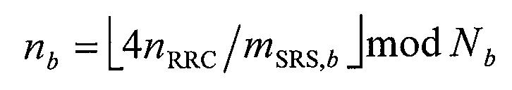
사운딩 참조 신호의 주파수 도약이 비활성화된 경우, 즉 b hop ≥ B SRS 인 경우, 주파수 위치 인덱스 n b 는 아래 수학식 7와 같이 일정한 값을 갖는다. 여기서 n RRC 는 상위 계층에서 주어지는 파라미터이다.If the frequency hopping of the sounding reference signal is disabled, that is, b hop ≥ B SRS If is, the frequency position index n b Has a constant value as shown in
한편, 사운딩 참조 신호의 주파수 도약이 활성화된 경우, 즉 bhop<BSRS 인 경우, 주파수 위치 인덱스 nb 는 아래 수학식 8 및 수학식 9에 의하여 정의된다.On the other hand, when the frequency hopping of the sounding reference signal is activated, that is, when b hop <B SRS , the frequency position index n b is defined by


여기서 n SRS 는 사운딩 참조 신호를 송신한 횟수를 계산하는 파라미터이며 아래 수학식 10에 의한다.Here n n SRS is a parameter that calculates the number of times the sounding reference signal is transmitted by

수학식 10에서 T SRS 는 사운딩 참조 신호의 주기이며, T offset 은 사운딩 참조 신호의 서브프레임 오프셋을 지칭한다. 또한, n s 는 슬롯 번호, n f 는 프레임 번호를 지칭한다.In
단말 특정한 사운딩 참조 신호의 주기 T SRS 와 서브프레임 오프셋 T offset 를 설정하기 위한 단말 특정 사운딩 참조 신호 설정 인덱스( I SRS )는 FDD와 TDD에 따라 각각 아래 표 5와 표 6와 같이 나타낸다. 특히 표 5는 FDD인 경우, 표 6은 TDD인 경우를 나타낸다.Period T SRS and Subframe Offset T offset of UE-specific Sounding Reference Signal UE-specific sounding reference signal configuration index ( I SRS) ) Are shown in Tables 5 and 6, respectively, according to FDD and TDD. In particular, Table 5 shows the case of FDD, and Table 6 shows the case of TDD.


위에서 설명한 기존 LTE 시스템의 사운딩 참조 신호는 주기적 사운딩 참조 신호를 의미한다. 한편, LTE-A 시스템에서는 이벤트 발생 조건부 사운딩 참조 신호인 추가적 사운딩 참조 신호가 정의될 수 있다. 즉, 상향링크 MIMO 전송을 위하여 기지국이 사운딩 참조 신호 전송을 요청한 경우 또는 다른 이유에 의하여 기지국이 상향링크 채널 상태 정보를 요청한 경우 등에는 LTE-A 시스템에서 정의하는 추가적 사운딩 참조 신호가 상기 주기적 사운딩 참조 신호와 별개로 전송될 필요가 있다.The sounding reference signal of the conventional LTE system described above means a periodic sounding reference signal. Meanwhile, in the LTE-A system, an additional sounding reference signal that is an event occurrence conditional sounding reference signal may be defined. That is, when the base station requests sounding reference signal transmission for uplink MIMO transmission or when the base station requests uplink channel state information for another reason, the additional sounding reference signal defined by the LTE-A system is periodically transmitted. It needs to be transmitted separately from the sounding reference signal.
한편, 추가적 사운딩 참조 신호의 전송을 위하여 기존 사운딩 참조 신호를 전송하기 위한 자원을 재사용하는 것을 고려할 수 있으며, 이 경우, 하나의 서브프레임의 마지막 심볼을 통하여 상기 주기적 사운딩 참조 신호와 상기 추가적 사운딩 참조 신호가 동시에 할당될 수 있으므로, 이를 효과적으로 다중화하는 방법이 요구된다. 이하에서는, 주기적 사운딩 참조 신호와 추가적 사운딩 참조 신호의 다중화 방법에 관하여 구체적으로 살펴본다.On the other hand, it may be considered to reuse the resources for transmitting the existing sounding reference signal for the transmission of the additional sounding reference signal, in this case, the periodic sounding reference signal and the additional through the last symbol of one subframe Since sounding reference signals can be assigned at the same time, a method of effectively multiplexing them is required. Hereinafter, a multiplexing method of the periodic sounding reference signal and the additional sounding reference signal will be described in detail.
1) 주기적 사운딩 참조 신호와 추가적 사운딩 참조 신호의 다중화 방법의 첫번째 방안으로서, 서로 다른 반복 인자(Repetition Factor)을 사용하여 다중화하는 방안을 제안한다. 보다 구체적으로, LTE 시스템에서 정의된 주기적 사운딩 참조 신호는 반복 인자 값으로 2 를 사용한다. 즉, 전송 콤 파라미터가 0 인 경우 홀수 인덱스(혹은 짝수 인덱스)를 갖는 부반송파를 통하여 해당 단말 특정 사운딩 대역폭으로 주기적 사운딩 참조 신호를 전송하고, 전송 콤 파라미터가 1 인 경우 짝수 인덱스(혹은 홀수 인덱스)를 갖는 부반송파를 통하여 주기적 사운딩 참조 신호를 전송하는 것으로 정의되어 있다.1) As a first method of a multiplexing method of a periodic sounding reference signal and an additional sounding reference signal, a method of multiplexing using different repetition factors is proposed. More specifically, the periodic sounding reference signal defined in the LTE system uses 2 as the repetition factor value. That is, when the transmission comb parameter is 0, a periodic sounding reference signal is transmitted through a subcarrier having an odd index (or even index) at a corresponding UE-specific sounding bandwidth, and when the transmission comb parameter is 1, an even index (or odd index) Is defined as transmitting a periodic sounding reference signal through a subcarrier with
이와 같은 경우라면, 하나의 심볼을 통하여 주기적 사운딩 참조 신호와 추가적 사운딩 참조 신호를 동시에 전송하여야 한다면, 양 신호에 서로 다른 전송 콤 파라미터를 설정하여 동시에 전송 가능하도록 할 수 있다.In this case, if the periodic sounding reference signal and the additional sounding reference signal must be transmitted at the same time through one symbol, different transmission comb parameters can be set to both signals so that they can be transmitted simultaneously.
도 6 은 본 발명의 실시예에 따른 주기적 사운딩 참조 신호와 추가적 사운딩 참조 신호의 다중화 방법의 예시도이다. 다만, 도 6 에서는 설명의 편의를 위하여 주기적 사운딩 참조 신호의 대역폭과 추가적 사운딩 참조 신호의 대역폭은 전체 사운딩 대역의 절반인 것으로 가정한다.6 is an exemplary diagram of a multiplexing method of a periodic sounding reference signal and an additional sounding reference signal according to an embodiment of the present invention. However, in FIG. 6, for convenience of explanation, it is assumed that the bandwidth of the periodic sounding reference signal and the bandwidth of the additional sounding reference signal are half of the total sounding band.
도 6 을 참조하면, 주기적 사운딩 참조 신호에 전송 콤 파라미터 0 을 설정하여 홀수 인덱스를 갖는 부반송파를 통하여 해당 단말 특정 사운딩 대역폭으로 주기적 사운딩 참조 신호를 전송하고, 추가적 사운딩 참조 신호에 전송 콤 파라미터가 1 을 설정하여 짝수 인덱스를 갖는 부반송파를 통하여 추가적 사운딩 참조 신호를 전송하는 것을 알 수 있다.Referring to FIG. 6, a
2) 주기적 사운딩 참조 신호와 추가적 사운딩 참조 신호의 다중화 방법의 두번째 방안으로서, 주기적 사운딩 참조 신호와 추가적 사운딩 참조 신호가 서로 다른 시간적 자원을 통하여 전송되도록, 상기 추가적 사운딩 참조 신호가 전송되는 서브프레임의 설정을 상기 주기적 사운딩 참조 신호가 전송되도록 설정된 서브프레임을 기준으로 오프셋 값으로 설정하여 다중화하는 방안을 고려할 수 있다. 즉, 주기적 사운딩 참조 신호와 추가적 사운딩 참조 신호를 시분할 다중화 방식으로 자원을 할당하여 전송하는 방식이라고 할 수 있다. 이러한 서브프레임 오프셋 값은 반 정적으로 RRC 계층을 통하여 시그널링될 수 있고, 혹은 동적으로 L1/L2 제어 시그널링을 통하여 지시될 수 있다.2) As a second method of the multiplexing method of the periodic sounding reference signal and the additional sounding reference signal, the additional sounding reference signal is transmitted such that the periodic sounding reference signal and the additional sounding reference signal are transmitted through different temporal resources. Multiplexing may be considered by setting a subframe to be an offset value based on a subframe in which the periodic sounding reference signal is transmitted. That is, it may be said that a method of allocating and transmitting resources of the periodic sounding reference signal and the additional sounding reference signal by time division multiplexing. This subframe offset value may be semi-statically signaled through the RRC layer, or may be dynamically indicated through the L1 / L2 control signaling.
이를 보다 구체적으로 설명하면, 주기적 사운딩 참조 신호의 주기가 1ms 인 경우를 제외하고 해당 서브프레임에서는 주기적 사운딩 참조 신호 또는 추가적 사운딩 참조 신호 중 하나의 전송 시점에서 서브프레임 오프셋 값이 적용하여 전송 지연시킨다. 예를 들어, 주기적 사운딩 참조 신호의 주기가 2ms(혹은 2 서브프레임)인 경우, 상기 서브프레임 오프셋 값은 1ms(혹은 1 서브프레임)으로 설정할 수 있다. 또한, 주기적 사운딩 참조 신호의 주기가 5ms(혹은 5 서브프레임)인 경우, 상기 서브프레임 오프셋 값은 1, 2, 3, 4ms(혹은 1, 2, 3, 4 서브프레임) 중 하나로 설정할 수 있다. 마찬가지로, 주기적 사운딩 참조 신호의 주기가 10ms(혹은 10 서브프레임)인 경우, 상기 서브프레임 오프셋 값은 1, 2, 3, 4,…, 9ms(혹은 1, 2, 3, 4,…, 9서브프레임) 중 하나로 설정할 수 있다.In more detail, except for a case in which the periodic sounding reference signal has a period of 1 ms, the subframe offset value is applied at the time of transmission of one of the periodic sounding reference signal or the additional sounding reference signal. Delay. For example, when the period of the periodic sounding reference signal is 2 ms (or 2 subframes), the subframe offset value may be set to 1 ms (or 1 subframe). In addition, when the period of the periodic sounding reference signal is 5ms (or 5 subframes), the subframe offset value may be set to one of 1, 2, 3, 4ms (or 1, 2, 3, 4 subframes). . Similarly, when the period of the periodic sounding reference signal is 10 ms (or 10 subframes), the subframe offset values are 1, 2, 3, 4,... , 9ms (or 1, 2, 3, 4, ..., 9 subframes).
도 7 은 본 발명의 다른 실시예에 따른 주기적 사운딩 참조 신호와 추가적 사운딩 참조 신호의 다중화 방법의 예시도이다.7 is an exemplary diagram of a multiplexing method of a periodic sounding reference signal and an additional sounding reference signal according to another embodiment of the present invention.
도 7 을 참조하면, 주기가 2 서브프레임 주기적 사운딩 참조 신호가 송신되는 중에 서브프레임 인덱스 2(700), 서브프레임 인덱스 5(705) 및 서브프레임 인덱스 9(710)에서 단말이 추가적 사운딩 참조 신호를 기지국으로 전송하도록 기지국이 지시하였다고 가정한다. 이와 같은 경우, 본 발명의 다른 실시예에서는 서브프레임 오프셋 값으로 1 서브프레임을 설정하여 시분할 다중화 방식으로 전송할 수 있다. 즉, 서브프레임 인덱스 2(700)에서는 주기적 사운딩 참조 신호를 위한 자원이 할당되지 않으므로 추가적 사운딩 참조 신호를 위한 별도의 서프프레임 오프셋이 불필요하지만, 서브프레임 인덱스 5(705) 및 서브프레임 인덱스 9(710)에서는 서브프레임 오프셋 값으로 1 서브프레임을 설정하여 서브프레임 인덱스 6 및 서브프레임 인덱스 10에서 상기 추가적 사운딩 참조 신호를 전송할 수 있다.Referring to FIG. 7, the UE additionally refers to additional sounding at
3) 마지막으로, 주기적 사운딩 참조 신호와 추가적 사운딩 참조 신호가 동일한 심볼을 통하여 전송되도록 설정된 경우, 단일 반송파 특성을 유지하기 위하여 해당 서브프레임의 해당 심볼에서 두 신호 중 하나의 사운딩 참조 신호의 드랍핑(dropping)하는 방안을 고려할 수 있다.3) Finally, when the periodic sounding reference signal and the additional sounding reference signal are set to be transmitted through the same symbol, in order to maintain a single carrier characteristic, the sounding reference signal of one of the two signals in the corresponding symbol of the corresponding subframe is maintained. A dropping scheme may be considered.
보다 구체적으로, 추가적 사운딩 참조 신호는 1 회성 전송일 수 있고, 또한 상향링크 MIMO 전송을 지원하기 위하여 복수의 안테나에 대한 전송일 수 있다. 따라서, 이러한 경우라면, 추가적 사운딩 참조 신호의 우선 순위가 주기적 사운딩 참조 신호보다 크다고 볼 수 있으므로, 해당 서브프레임에서의 주기적 사운딩 참조 신호를 드랍핑한다.More specifically, the additional sounding reference signal may be a one-time transmission and may also be a transmission for a plurality of antennas to support uplink MIMO transmission. Therefore, in this case, since the priority of the additional sounding reference signal is greater than the periodic sounding reference signal, the periodic sounding reference signal in the corresponding subframe is dropped.
그러나, 상기 주기적 사운딩 참조 신호가 전 대역 사운딩인 경우에는 상기 주기적 사운딩 참조 신호를 전송하고 상기 추가적 사운딩 참조 신호를 드랍핑하는 것이 바람직하다. 다만, 이러한 경우 스케쥴러가 추가적 사운딩 참조 신호의 전송 여부에 관한 지시를 동적으로 시그널링한다는 가정이 요구될 수 있다. 따라서, 단말 동작의 입장에서 추가적인 비주기적 사운딩 참조신호와 주기적 사운딩 참조 신호가 동시에 하나의 서브 프레임과 동일한 심볼에서 구성되는 경우, 비주기적 사운딩 참조 신호를 드랍핑하는 동작을 단말에게 적용할 수 있다.However, when the periodic sounding reference signal is full band sounding, it is preferable to transmit the periodic sounding reference signal and drop the additional sounding reference signal. In this case, however, it may be required to assume that the scheduler dynamically signals an indication as to whether to transmit an additional sounding reference signal. Accordingly, when the additional aperiodic sounding reference signal and the periodic sounding reference signal are configured in the same symbol as one subframe at the same time, the operation of dropping the aperiodic sounding reference signal may be applied to the terminal. Can be.
도 8 은 본 발명의 일 실시예에 따른 통신 송수신기의 블록 구성도를 예시한다. 송수신기는 기지국 또는 단말의 일부일 수 있다.8 illustrates a block diagram of a communication transceiver according to an embodiment of the present invention. The transceiver may be part of a base station or a terminal.
도 8을 참조하면, 송수신기(800)는 프로세서(810), 메모리(820), RF 모듈(830), 디스플레이 모듈(840) 및 사용자 인터페이스 모듈(850)을 포함한다.Referring to FIG. 8, the
송수신기(800)는 설명의 편의를 위해 도시된 것으로서 일부 모듈은 생략될 수 있다. 또한, 송수신기(800)는 필요한 모듈을 더 포함할 수 있다. 또한, 송수신기(800)에서 일부 모듈은 보다 세분화된 모듈로 구분될 수 있다. 프로세서(810)는 도면을 참조하여 예시한 본 발명의 실시예에 따른 동작을 수행하도록 구성된다.The
구체적으로, 송수신기(800)가 기지국의 일부인 경우에 프로세서(810)는 제어 신호를 생성하여 복수의 주파수 블록 내에 설정된 제어 채널로 맵핑하는 기능을 수행할 수 있다. 또한, 송수신기(800)가 단말의 일부인 경우에 프로세서(810)는 복수의 주파수 블록으로부터 수신된 신호로부터 자신에게 지시된 제어 채널을 확인하고 그로부터 제어 신호를 추출할 수 있다.In detail, when the
그 후, 프로세서(810)는 제어 신호에 기초하여 필요한 동작을 수행할 수 있다. 프로세서(810)의 자세한 동작은 도 1 내지 도 7에 기재된 내용을 참조할 수 있다.Thereafter, the
메모리(820)는 프로세서(810)에 연결되며 오퍼레이팅 시스템, 어플리케이션, 프로그램 코드, 데이터 등을 저장한다. RF 모듈(830)은 프로세서(810)에 연결되며 기저대역 신호를 무선 신호를 변환하거나 무선신호를 기저대역 신호로 변환하는 기능을 수행한다. 이를 위해, RF 모듈(830)은 아날로그 변환, 증폭, 필터링 및 주파수 상향 변환 또는 이들의 역과정을 수행한다. 디스플레이 모듈(840)은 프로세서(810)에 연결되며 다양한 정보를 디스플레이한다. 디스플레이 모듈(840)은 이로 제한되는 것은 아니지만 LCD(Liquid Crystal Display), LED(Light Emitting Diode), OLED(Organic Light Emitting Diode)와 같은 잘 알려진 요소를 사용할 수 있다. 사용자 인터페이스 모듈(850)은 프로세서(810)와 연결되며 키패드, 터치 스크린 등과 같은 잘 알려진 사용자 인터페이스의 조합으로 구성될 수 있다.The
이상에서 설명된 실시예들은 본 발명의 구성요소들과 특징들이 소정 형태로 결합된 것들이다. 각 구성요소 또는 특징은 별도의 명시적 언급이 없는 한 선택적인 것으로 고려되어야 한다. 각 구성요소 또는 특징은 다른 구성요소나 특징과 결합되지 않은 형태로 실시될 수 있다. 또한, 일부 구성요소들 및/또는 특징들을 결합하여 본 발명의 실시예를 구성하는 것도 가능하다. 본 발명의 실시예들에서 설명되는 동작들의 순서는 변경될 수 있다. 어느 실시예의 일부 구성이나 특징은 다른 실시예에 포함될 수 있고, 또는 다른 실시예의 대응하는 구성 또는 특징과 교체될 수 있다. 특허청구범위에서 명시적인 인용 관계가 있지 않은 청구항들을 결합하여 실시예를 구성하거나 출원 후의 보정에 의해 새로운 청구항으로 포함시킬 수 있음은 자명하다.The embodiments described above are the components and features of the present invention are combined in a predetermined form. Each component or feature is to be considered optional unless stated otherwise. Each component or feature may be implemented in a form that is not combined with other components or features. It is also possible to combine some of the components and / or features to form an embodiment of the invention. The order of the operations described in the embodiments of the present invention may be changed. Some configurations or features of certain embodiments may be included in other embodiments, or may be replaced with corresponding configurations or features of other embodiments. It is obvious that the claims may be combined to form an embodiment by combining claims that do not have an explicit citation relationship in the claims or as new claims by post-application correction.
본 문서에서 본 발명의 실시예들은 주로 단말과 기지국 간의 데이터 송수신 관계를 중심으로 설명되었다. 본 문서에서 기지국에 의해 수행된다고 설명된 특정 동작은 경우에 따라서는 그 상위 노드(upper node)에 의해 수행될 수 있다. 즉, 기지국을 포함하는 복수의 네트워크 노드들(network nodes)로 이루어지는 네트워크에서 단말과의 통신을 위해 수행되는 다양한 동작들은 기지국 또는 기지국 이외의 다른 네트워크 노드들에 의해 수행될 수 있음은 자명하다. 기지국은 고정국(fixed station), Node B, eNode B(eNB), 억세스 포인트(access point) 등의 용어에 의해 대체될 수 있다. 또한, 단말은 UE(User Equipment), MS(Mobile Station), MSS(Mobile Subscriber Station) 등의 용어로 대체될 수 있다.In this document, the embodiments of the present invention have been mainly described with reference to the data transmission / reception relationship between the terminal and the base station. The specific operation described herein as being performed by the base station may be performed by its upper node, in some cases. That is, it is apparent that various operations performed for communication with a terminal in a network including a plurality of network nodes including a base station can be performed by a network node other than the base station or the base station. A base station may be replaced by terms such as a fixed station, a Node B, an eNode B (eNB), an access point, and the like. In addition, the terminal may be replaced with terms such as a user equipment (UE), a mobile station (MS), a mobile subscriber station (MSS), and the like.
본 발명에 따른 실시예는 다양한 수단, 예를 들어, 하드웨어, 펌웨어(firmware), 소프트웨어 또는 그것들의 결합 등에 의해 구현될 수 있다. 하드웨어에 의한 구현의 경우, 본 발명의 일 실시예는 하나 또는 그 이상의 ASICs(application specific integrated circuits), DSPs(digital signal processors), DSPDs(digital signal processing devices), PLDs(programmable logic devices), FPGAs(field programmable gate arrays), 프로세서, 콘트롤러, 마이크로 콘트롤러, 마이크로 프로세서 등에 의해 구현될 수 있다.Embodiments according to the present invention may be implemented by various means, for example, hardware, firmware, software, or a combination thereof. In the case of a hardware implementation, an embodiment of the present invention may include one or more application specific integrated circuits (ASICs), digital signal processors (DSPs), digital signal processing devices (DSPDs), programmable logic devices (PLDs), FPGAs ( field programmable gate arrays), processors, controllers, microcontrollers, microprocessors, and the like.
펌웨어나 소프트웨어에 의한 구현의 경우, 본 발명의 일 실시예는 이상에서 설명된 기능 또는 동작들을 수행하는 모듈, 절차, 함수 등의 형태로 구현될 수 있다. 소프트웨어 코드는 메모리 유닛에 저장되어 프로세서에 의해 구동될 수 있다. 상기 메모리 유닛은 상기 프로세서 내부 또는 외부에 위치하여, 이미 공지된 다양한 수단에 의해 상기 프로세서와 데이터를 주고 받을 수 있다.In the case of implementation by firmware or software, an embodiment of the present invention may be implemented in the form of a module, procedure, function, etc. that performs the functions or operations described above. The software code may be stored in a memory unit and driven by a processor. The memory unit may be located inside or outside the processor, and may exchange data with the processor by various known means.
본 발명은 본 발명의 특징을 벗어나지 않는 범위에서 다른 특정한 형태로 구체화될 수 있음은 당업자에게 자명하다. 따라서, 상기의 상세한 설명은 모든 면에서 제한적으로 해석되어서는 아니되고 예시적인 것으로 고려되어야 한다. 본 발명의 범위는 첨부된 청구항의 합리적 해석에 의해 결정되어야 하고, 본 발명의 등가적 범위 내에서의 모든 변경은 본 발명의 범위에 포함된다.It will be apparent to those skilled in the art that the present invention may be embodied in other specific forms without departing from the spirit of the invention. Accordingly, the above detailed description should not be construed as limiting in all aspects and should be considered as illustrative. The scope of the invention should be determined by reasonable interpretation of the appended claims, and all changes within the equivalent scope of the invention are included in the scope of the invention.
본 발명은 무선 통신 시스템에 적용될 수 있다. 보다 구체적으로, 본 발명은 주파수 집성이 적용된 무선 통신 시스템에서 사운딩 참조 신호를 송신하는 방법 및 장치에 적용될 수 있다.The present invention can be applied to a wireless communication system. More specifically, the present invention can be applied to a method and apparatus for transmitting a sounding reference signal in a wireless communication system to which frequency aggregation is applied.
Claims (14)
상위 계층에 의하여, 상기 사운딩 참조 신호를 위한 적어도 하나의 파라미터를 설정하는 단계; 및
상기 적어도 하나의 파라미터에 기반하여, 상기 상위 계층에 의하여 트리거링되는 제 1 사운딩 참조 신호 및 하향링크 제어 정보에 의하여 트리거링되는 제 2 사운딩 참조 신호 중 적어도 하나를 기지국으로 송신하는 단계를 포함하고,
상기 제 1 사운딩 참조 신호의 전송과 상기 제 2 사운딩 참조 신호의 전송이 동일한 서브프레임에서 발생하는 경우, 상기 제 2 사운딩 참조 신호만 상기 기지국으로 송신하는 것을 특징으로 하는,
사운딩 참조 신호 송신 방법.A method for transmitting a sounding reference signal by a terminal in a wireless communication system,
Setting, by an upper layer, at least one parameter for the sounding reference signal; And
Transmitting at least one of a first sounding reference signal triggered by the higher layer and a second sounding reference signal triggered by downlink control information to the base station based on the at least one parameter,
When the transmission of the first sounding reference signal and the transmission of the second sounding reference signal occur in the same subframe, only the second sounding reference signal is transmitted to the base station.
Method of transmitting a sounding reference signal.
상기 제 1 사운딩 참조 신호와 상기 제 2 사운딩 참조 신호는 서브프레임의 마지막 심볼 상에서 송신되는 것을 특징으로 하는,
사운딩 참조 신호 송신 방법.The method of claim 1,
Wherein the first sounding reference signal and the second sounding reference signal are transmitted on a last symbol of a subframe,
Method of transmitting a sounding reference signal.
상기 하향링크 제어 정보는,
하향링크 물리 제어 채널을 통하여 상기 기지국으로부터 수신되는 것을 특징으로 하는,
사운딩 참조 신호 송신 방법.The method of claim 1,
The downlink control information,
Characterized in that received from the base station via a downlink physical control channel,
Method of transmitting a sounding reference signal.
상기 제 1 사운딩 참조 신호는,
상기 기지국으로 주기적으로 송신되는 것을 특징으로 하는,
사운딩 참조 신호 송신 방법.The method of claim 1,
The first sounding reference signal is,
Characterized in that periodically transmitted to the base station,
Method of transmitting a sounding reference signal.
상기 제 1 사운딩 참조 신호는,
상기 기지국으로 비주기적으로 송신되는 것을 특징으로 하는,
사운딩 참조 신호 송신 방법.The method of claim 1,
The first sounding reference signal is,
Characterized in that it is transmitted aperiodically to the base station,
Method of transmitting a sounding reference signal.
상위 계층 시그널링에 의하여, 사운딩 참조 신호를 위한 적어도 하나의 파라미터를 설정하기 위한 프로세서; 및
상기 적어도 하나의 파라미터에 기반하여, 상기 상위 계층 시그널링에 의하여 트리거링되는 제 1 사운딩 참조 신호 및 하향링크 제어 정보에 의하여 트리거링되는 제 2 사운딩 참조 신호 중 적어도 하나를 기지국으로 송신하기 위한 프로세서를 포함하고,
상기 제 1 사운딩 참조 신호의 전송과 상기 제 2 사운딩 참조 신호의 전송이 동일한 서브프레임에서 발생하는 경우, 상기 제 2 사운딩 참조 신호만 상기 기지국으로 송신하는 것을 특징으로 하는,
단말 장치.A terminal device in a wireless communication system,
A processor for setting at least one parameter for a sounding reference signal by higher layer signaling; And
A processor for transmitting to the base station at least one of a first sounding reference signal triggered by the higher layer signaling and a second sounding reference signal triggered by downlink control information based on the at least one parameter. and,
When the transmission of the first sounding reference signal and the transmission of the second sounding reference signal occur in the same subframe, only the second sounding reference signal is transmitted to the base station.
Terminal device.
상기 제 1 사운딩 참조 신호와 상기 제 2 사운딩 참조 신호는 서브프레임의 마지막 심볼 상에서 송신되는 것을 특징으로 하는,
단말 장치.The method according to claim 6,
Wherein the first sounding reference signal and the second sounding reference signal are transmitted on a last symbol of a subframe,
Terminal device.
상기 기지국으로부터 상기 하향링크 제어 정보를 하향링크 물리 제어 채널을 통하여 수신하기 위한 수신 모듈을 더 포함하는 것을 특징으로 하는,
단말 장치.The method according to claim 6,
And a receiving module for receiving the downlink control information from the base station through a downlink physical control channel.
Terminal device.
상기 제 1 사운딩 참조 신호는,
상기 기지국으로 주기적으로 송신되는 것을 특징으로 하는,
단말 장치.The method according to claim 6,
The first sounding reference signal is,
Characterized in that periodically transmitted to the base station,
Terminal device.
상기 제 1 사운딩 참조 신호는,
상기 기지국으로 비주기적으로 송신되는 것을 특징으로 하는,
단말 장치.The method according to claim 6,
The first sounding reference signal is,
Characterized in that it is transmitted aperiodically to the base station,
Terminal device.
Priority Applications (7)
| Application Number | Priority Date | Filing Date | Title |
|---|---|---|---|
| KR1020100045447A KR101128817B1 (en) | 2009-05-15 | 2010-05-14 | Method for transmitting sounding reference signal in wireless communication system and apparatus therefor |
| US13/320,514 US8351347B2 (en) | 2009-05-15 | 2010-05-17 | Method and apparatus for transmitting sounding reference signal in radio communication system |
| CN201080030365.9A CN102484877B (en) | 2009-05-15 | 2010-05-17 | Method and apparatus for transmitting sounding reference signal in radio communication system |
| PCT/KR2010/003104 WO2010131934A2 (en) | 2009-05-15 | 2010-05-17 | Method and apparatus for transmitting sounding reference signal in radio communication system |
| JP2012510759A JP5709848B2 (en) | 2009-05-15 | 2010-05-17 | Sounding reference signal transmission method and apparatus for wireless communication system |
| EP10775136.4A EP2432292B1 (en) | 2009-05-15 | 2010-05-17 | Method and apparatus for transmitting sounding reference signal in radio communication system |
| US13/693,886 US8923154B2 (en) | 2009-05-15 | 2012-12-04 | Method and apparatus for transmitting sounding reference signal in radio communication system |
Applications Claiming Priority (5)
| Application Number | Priority Date | Filing Date | Title |
|---|---|---|---|
| US17881809P | 2009-05-15 | 2009-05-15 | |
| US61/178,818 | 2009-05-15 | ||
| US30508010P | 2010-02-16 | 2010-02-16 | |
| US61/305,080 | 2010-02-16 | ||
| KR1020100045447A KR101128817B1 (en) | 2009-05-15 | 2010-05-14 | Method for transmitting sounding reference signal in wireless communication system and apparatus therefor |
Publications (2)
| Publication Number | Publication Date |
|---|---|
| KR20100123655A KR20100123655A (en) | 2010-11-24 |
| KR101128817B1 true KR101128817B1 (en) | 2012-03-23 |
Family
ID=43085482
Family Applications (1)
| Application Number | Title | Priority Date | Filing Date |
|---|---|---|---|
| KR1020100045447A KR101128817B1 (en) | 2009-05-15 | 2010-05-14 | Method for transmitting sounding reference signal in wireless communication system and apparatus therefor |
Country Status (6)
| Country | Link |
|---|---|
| US (2) | US8351347B2 (en) |
| EP (1) | EP2432292B1 (en) |
| JP (1) | JP5709848B2 (en) |
| KR (1) | KR101128817B1 (en) |
| CN (1) | CN102484877B (en) |
| WO (1) | WO2010131934A2 (en) |
Cited By (1)
| Publication number | Priority date | Publication date | Assignee | Title |
|---|---|---|---|---|
| WO2014014219A1 (en) * | 2012-07-19 | 2014-01-23 | 주식회사 케이티 | Method and apparatus for controlling transmission of aperiodic sounding reference signal in mobile communication network |
Families Citing this family (52)
| Publication number | Priority date | Publication date | Assignee | Title |
|---|---|---|---|---|
| KR101294815B1 (en) | 2009-05-15 | 2013-08-08 | 엘지전자 주식회사 | Method for transmitting sounding reference signal in wireless communication system and apparatus therefor |
| EP2482590B1 (en) | 2009-09-21 | 2017-11-08 | LG Electronics Inc. | Method for transmitting a sounding reference signal in a wireless communication system, and apparatus for same |
| JP5868322B2 (en) | 2009-09-21 | 2016-02-24 | エルジー エレクトロニクス インコーポレイティド | Method and apparatus for transferring sounding reference signal in wireless communication system |
| EP2497297B1 (en) * | 2009-11-02 | 2021-10-13 | HMD Global Oy | Scheme for multi-cell ul sounding transmission |
| EP2522190B1 (en) * | 2010-01-08 | 2018-02-07 | Sharp Kabushiki Kaisha | Mobile communication method and system for sounding reference signal transmission, and base station, user equipment and integrated circuit therein |
| WO2011090259A2 (en) * | 2010-01-19 | 2011-07-28 | 엘지전자 주식회사 | Method for transmitting sounding reference signal in wireless communication system and apparatus for same |
| JP5538930B2 (en) | 2010-02-04 | 2014-07-02 | シャープ株式会社 | Mobile station apparatus, base station apparatus, radio communication system, and radio communication method |
| US8848520B2 (en) * | 2010-02-10 | 2014-09-30 | Qualcomm Incorporated | Aperiodic sounding reference signal transmission method and apparatus |
| WO2011135858A1 (en) | 2010-04-30 | 2011-11-03 | パナソニック株式会社 | Wireless communication device and method for controlling transmission power |
| BR112012031319A2 (en) * | 2010-06-28 | 2016-10-25 | Ericsson Telefon Ab L M | "Methods and arrangements for reducing supplemental signaling information in a wireless communication system using carrier aggregation" |
| CN103155472B (en) * | 2010-08-13 | 2015-11-25 | 黑莓有限公司 | For resource allocation methods and the signaling of aperiodicity channel detection |
| CN102469609B (en) * | 2010-11-16 | 2016-03-09 | 华为技术有限公司 | The sending method of measuring reference signals and configuration indicating method and equipment |
| CN102076026B (en) * | 2011-01-06 | 2013-06-05 | 大唐移动通信设备有限公司 | Sounding reference signal transmitting method, device and terminal |
| US8395985B2 (en) | 2011-07-25 | 2013-03-12 | Ofinno Technologies, Llc | Time alignment in multicarrier OFDM network |
| CN103782532B (en) * | 2011-09-07 | 2016-12-14 | Lg电子株式会社 | In a wireless communication system upward signal is sent the method to base station and the device of use the method from subscriber equipment |
| CN104170506B (en) | 2011-10-08 | 2018-07-31 | 华为技术有限公司 | Sounding reference signal transmission enhancement |
| US9237537B2 (en) | 2012-01-25 | 2016-01-12 | Ofinno Technologies, Llc | Random access process in a multicarrier base station and wireless device |
| US8897248B2 (en) | 2012-01-25 | 2014-11-25 | Ofinno Technologies, Llc | Multicarrier signal transmission in wireless communications |
| US8995405B2 (en) | 2012-01-25 | 2015-03-31 | Ofinno Technologies, Llc | Pathloss reference configuration in a wireless device and base station |
| US9084270B2 (en) | 2012-04-01 | 2015-07-14 | Ofinno Technologies, Llc | Radio access for a wireless device and base station |
| US11943813B2 (en) | 2012-04-01 | 2024-03-26 | Comcast Cable Communications, Llc | Cell grouping for wireless communications |
| US9215678B2 (en) | 2012-04-01 | 2015-12-15 | Ofinno Technologies, Llc | Timing advance timer configuration in a wireless device and a base station |
| US8964593B2 (en) | 2012-04-16 | 2015-02-24 | Ofinno Technologies, Llc | Wireless device transmission power |
| US11252679B2 (en) | 2012-04-16 | 2022-02-15 | Comcast Cable Communications, Llc | Signal transmission power adjustment in a wireless device |
| US8989128B2 (en) | 2012-04-20 | 2015-03-24 | Ofinno Technologies, Llc | Cell timing in a wireless device and base station |
| US9210664B2 (en) | 2012-04-17 | 2015-12-08 | Ofinno Technologies. LLC | Preamble transmission in a wireless device |
| US11825419B2 (en) | 2012-04-16 | 2023-11-21 | Comcast Cable Communications, Llc | Cell timing in a wireless device and base station |
| US8995381B2 (en) | 2012-04-16 | 2015-03-31 | Ofinno Technologies, Llc | Power control in a wireless device |
| US11582704B2 (en) | 2012-04-16 | 2023-02-14 | Comcast Cable Communications, Llc | Signal transmission power adjustment in a wireless device |
| US9179425B2 (en) | 2012-04-17 | 2015-11-03 | Ofinno Technologies, Llc | Transmit power control in multicarrier communications |
| US9084228B2 (en) | 2012-06-20 | 2015-07-14 | Ofinno Technologies, Llc | Automobile communication device |
| US11622372B2 (en) | 2012-06-18 | 2023-04-04 | Comcast Cable Communications, Llc | Communication device |
| US9179457B2 (en) | 2012-06-20 | 2015-11-03 | Ofinno Technologies, Llc | Carrier configuration in wireless networks |
| US9107206B2 (en) | 2012-06-18 | 2015-08-11 | Ofinne Technologies, LLC | Carrier grouping in multicarrier wireless networks |
| US9113387B2 (en) | 2012-06-20 | 2015-08-18 | Ofinno Technologies, Llc | Handover signalling in wireless networks |
| US9210619B2 (en) | 2012-06-20 | 2015-12-08 | Ofinno Technologies, Llc | Signalling mechanisms for wireless device handover |
| US8971298B2 (en) | 2012-06-18 | 2015-03-03 | Ofinno Technologies, Llc | Wireless device connection to an application server |
| US11882560B2 (en) | 2012-06-18 | 2024-01-23 | Comcast Cable Communications, Llc | Carrier grouping in multicarrier wireless networks |
| KR101407094B1 (en) | 2012-10-31 | 2014-06-16 | 엘지전자 주식회사 | Method and apparatus for transmitting uplink signal |
| WO2017006877A1 (en) * | 2015-07-03 | 2017-01-12 | シャープ株式会社 | Terminal device, base station device, communication method and integrated circuit |
| JP6785764B2 (en) * | 2015-07-03 | 2020-11-18 | シャープ株式会社 | Terminal device and communication method |
| US10411774B2 (en) | 2015-07-03 | 2019-09-10 | Sharp Kabushiki Kaisha | Terminal device, base station device, communication method, and integrated circuit using physical downlink shared channel transmission for efficient communication |
| US20200204971A1 (en) * | 2017-07-03 | 2020-06-25 | Ntt Docomo, Inc. | User apparatus and transmission method |
| KR102494268B1 (en) * | 2017-09-29 | 2023-02-02 | 삼성전자 주식회사 | Method and apparatus for transmitting a reference signal in a wireless communications system |
| WO2019066625A1 (en) | 2017-09-29 | 2019-04-04 | Samsung Electronics Co., Ltd. | A method and apparatus for transmitting reference signal in wireless communication system |
| KR102410474B1 (en) | 2017-11-17 | 2022-06-20 | 삼성전자주식회사 | Method and apparatus for transmission and reception of reference signal in wirelss communication system |
| KR102587077B1 (en) * | 2017-12-28 | 2023-10-10 | 삼성전자 주식회사 | Method and apparatus for reference signal configuration for non-linear precoding |
| CN110034841B (en) * | 2018-01-11 | 2021-01-12 | 华为技术有限公司 | Information transmission method and device and computer readable storage medium |
| CN111837351A (en) * | 2018-05-11 | 2020-10-27 | 株式会社Ntt都科摩 | Method for transmitting signals, corresponding user terminal and base station |
| US20200106646A1 (en) * | 2018-09-28 | 2020-04-02 | Qualcomm Incorporated | Aperiodic sounding reference signal (a-srs) configuration |
| WO2021090239A1 (en) * | 2019-11-08 | 2021-05-14 | Nokia Technologies Oy | Triggering of sounding reference signal transmission |
| US20220321312A1 (en) * | 2021-04-06 | 2022-10-06 | Mediatek Inc. | Partial Sounding Method for Sounding Reference Signal in Mobile Communications |
Citations (1)
| Publication number | Priority date | Publication date | Assignee | Title |
|---|---|---|---|---|
| US20090323664A1 (en) | 2008-06-25 | 2009-12-31 | Samsung Electronics., Ltd. | Method for transmitting a sounding reference signal in a lte tdd system |
Family Cites Families (13)
| Publication number | Priority date | Publication date | Assignee | Title |
|---|---|---|---|---|
| KR20080073028A (en) * | 2007-02-05 | 2008-08-08 | 삼성전자주식회사 | Apparatus and method for allcating resource to relay station in realy wireless communication system |
| CN102573086A (en) | 2007-03-01 | 2012-07-11 | 株式会社Ntt都科摩 | Image processing apparatus, image processing method, and program |
| JP5100745B2 (en) | 2007-03-01 | 2012-12-19 | 株式会社エヌ・ティ・ティ・ドコモ | Base station apparatus and communication control method |
| US8055301B2 (en) * | 2007-08-06 | 2011-11-08 | Mitsubishi Electric Research Laboratories, Inc. | Wireless networks incorporating implicit antenna selection based on received sounding reference signals |
| US8798183B2 (en) * | 2007-08-13 | 2014-08-05 | Qualcomm Incorporated | Feedback and rate adaptation for MIMO transmission in a time division duplexed (TDD) communication system |
| KR100943880B1 (en) | 2007-09-14 | 2010-02-24 | 주식회사 카서 | Method and system for near field communication based on zone |
| JP2009089064A (en) * | 2007-09-28 | 2009-04-23 | Toshiba Corp | Wireless transmitter and wireless receiver |
| US8483186B2 (en) * | 2007-12-10 | 2013-07-09 | Mitsubishi Electric Research Laboratories, Inc. | Method and system for generating antenna selection signals in wireless networks |
| US8331297B2 (en) * | 2007-12-10 | 2012-12-11 | Mitsubishi Electric Research Laboratories, Inc. | Method and system for generating antenna selection signals in wireless networks |
| JP5115186B2 (en) * | 2007-12-27 | 2013-01-09 | 富士通株式会社 | Control method in wireless communication system |
| EP2166694A3 (en) * | 2008-09-18 | 2012-01-04 | Samsung Electronics Co., Ltd. | Transmission of sounding reference signals in TDD communication systems |
| CN101404794B (en) * | 2008-09-24 | 2012-11-28 | 中兴通讯股份有限公司 | Transmission pretreating method for measurement reference signal, parameter transmitting and receiving method |
| US8654666B2 (en) * | 2008-11-03 | 2014-02-18 | Lg Electronics Inc. | Communication method and apparatus in multi-carrier system |
-
2010
- 2010-05-14 KR KR1020100045447A patent/KR101128817B1/en active IP Right Grant
- 2010-05-17 US US13/320,514 patent/US8351347B2/en active Active
- 2010-05-17 WO PCT/KR2010/003104 patent/WO2010131934A2/en active Application Filing
- 2010-05-17 CN CN201080030365.9A patent/CN102484877B/en active Active
- 2010-05-17 EP EP10775136.4A patent/EP2432292B1/en active Active
- 2010-05-17 JP JP2012510759A patent/JP5709848B2/en active Active
-
2012
- 2012-12-04 US US13/693,886 patent/US8923154B2/en active Active
Patent Citations (1)
| Publication number | Priority date | Publication date | Assignee | Title |
|---|---|---|---|---|
| US20090323664A1 (en) | 2008-06-25 | 2009-12-31 | Samsung Electronics., Ltd. | Method for transmitting a sounding reference signal in a lte tdd system |
Cited By (1)
| Publication number | Priority date | Publication date | Assignee | Title |
|---|---|---|---|---|
| WO2014014219A1 (en) * | 2012-07-19 | 2014-01-23 | 주식회사 케이티 | Method and apparatus for controlling transmission of aperiodic sounding reference signal in mobile communication network |
Also Published As
| Publication number | Publication date |
|---|---|
| EP2432292B1 (en) | 2019-07-10 |
| US20130094448A1 (en) | 2013-04-18 |
| EP2432292A2 (en) | 2012-03-21 |
| WO2010131934A2 (en) | 2010-11-18 |
| JP5709848B2 (en) | 2015-04-30 |
| WO2010131934A3 (en) | 2011-02-24 |
| JP2012527153A (en) | 2012-11-01 |
| US8351347B2 (en) | 2013-01-08 |
| CN102484877B (en) | 2014-08-06 |
| US20120076037A1 (en) | 2012-03-29 |
| EP2432292A4 (en) | 2013-03-06 |
| US8923154B2 (en) | 2014-12-30 |
| CN102484877A (en) | 2012-05-30 |
| KR20100123655A (en) | 2010-11-24 |
Similar Documents
| Publication | Publication Date | Title |
|---|---|---|
| KR101128817B1 (en) | Method for transmitting sounding reference signal in wireless communication system and apparatus therefor | |
| KR101294815B1 (en) | Method for transmitting sounding reference signal in wireless communication system and apparatus therefor | |
| KR101319903B1 (en) | Method for transmitting a sounding reference signal in a wireless communication system, and apparatus for same | |
| KR101306745B1 (en) | Method for transmitting a sounding reference signal in a wireless communication system, and apparatus for same | |
| KR101709499B1 (en) | Method for transmitting sounding reference signal in wireless communication system and apparatus therefor | |
| KR101435856B1 (en) | Method for transmitting an uplink signal in a wireless communication system, and apparatus for same | |
| KR101741397B1 (en) | Method for transmitting sounding reference signal in wireless communication system and apparatus therefor | |
| JP5739016B2 (en) | Sounding reference signal transmission method and apparatus therefor in multi-antenna wireless communication system | |
| KR102011821B1 (en) | Method for enabling terminal to transmit ack/nack response in wireless communication system and apparatus therefor | |
| KR101641971B1 (en) | Method for transmitting sounding reference signal in wireless communication system and apparatus therefor | |
| KR102032848B1 (en) | Method of operating an harq buffer for a dynamic sub-frame change and an apparatus for same | |
| KR102243665B1 (en) | Carrier setting and control method for direct communication between terminals in wireless communication system and apparatus therefor | |
| WO2011071291A2 (en) | Method for transmitting a sounding reference signal in an uplink comp communication system, and apparatus for same | |
| KR102052375B1 (en) | Method for setting an mtc terminal search area in a wireless communication system and an apparatus for same | |
| WO2011090259A2 (en) | Method for transmitting sounding reference signal in wireless communication system and apparatus for same | |
| WO2015190795A1 (en) | Method for controlling timing advance for direct communication between terminals in wireless communication system, and apparatus therefor | |
| KR20120129610A (en) | Method for transceiving downlink signal in wireless communication system and apparatus therefor |
Legal Events
| Date | Code | Title | Description |
|---|---|---|---|
| A201 | Request for examination | ||
| E701 | Decision to grant or registration of patent right | ||
| GRNT | Written decision to grant | ||
| FPAY | Annual fee payment |
Payment date: 20150224 Year of fee payment: 4 |
|
| FPAY | Annual fee payment |
Payment date: 20160224 Year of fee payment: 5 |
|
| FPAY | Annual fee payment |
Payment date: 20170214 Year of fee payment: 6 |
|
| FPAY | Annual fee payment |
Payment date: 20190214 Year of fee payment: 8 |