KR101026469B1 - Carrier frequency synchronization apparatus and method in ofdm system - Google Patents
Carrier frequency synchronization apparatus and method in ofdm system Download PDFInfo
- Publication number
- KR101026469B1 KR101026469B1 KR1020050115153A KR20050115153A KR101026469B1 KR 101026469 B1 KR101026469 B1 KR 101026469B1 KR 1020050115153 A KR1020050115153 A KR 1020050115153A KR 20050115153 A KR20050115153 A KR 20050115153A KR 101026469 B1 KR101026469 B1 KR 101026469B1
- Authority
- KR
- South Korea
- Prior art keywords
- frequency offset
- metric
- symbol
- carrier frequency
- fft
- Prior art date
Links
Images


Classifications
-
- H—ELECTRICITY
- H04—ELECTRIC COMMUNICATION TECHNIQUE
- H04L—TRANSMISSION OF DIGITAL INFORMATION, e.g. TELEGRAPHIC COMMUNICATION
- H04L27/00—Modulated-carrier systems
- H04L27/26—Systems using multi-frequency codes
- H04L27/2601—Multicarrier modulation systems
- H04L27/2647—Arrangements specific to the receiver only
- H04L27/2655—Synchronisation arrangements
- H04L27/2657—Carrier synchronisation
-
- H—ELECTRICITY
- H04—ELECTRIC COMMUNICATION TECHNIQUE
- H04J—MULTIPLEX COMMUNICATION
- H04J13/00—Code division multiplex systems
- H04J13/0007—Code type
- H04J13/0022—PN, e.g. Kronecker
-
- H—ELECTRICITY
- H04—ELECTRIC COMMUNICATION TECHNIQUE
- H04L—TRANSMISSION OF DIGITAL INFORMATION, e.g. TELEGRAPHIC COMMUNICATION
- H04L27/00—Modulated-carrier systems
- H04L27/26—Systems using multi-frequency codes
- H04L27/2601—Multicarrier modulation systems
- H04L27/2647—Arrangements specific to the receiver only
- H04L27/2649—Demodulators
- H04L27/265—Fourier transform demodulators, e.g. fast Fourier transform [FFT] or discrete Fourier transform [DFT] demodulators
-
- H—ELECTRICITY
- H04—ELECTRIC COMMUNICATION TECHNIQUE
- H04L—TRANSMISSION OF DIGITAL INFORMATION, e.g. TELEGRAPHIC COMMUNICATION
- H04L27/00—Modulated-carrier systems
- H04L27/26—Systems using multi-frequency codes
- H04L27/2601—Multicarrier modulation systems
- H04L27/2647—Arrangements specific to the receiver only
- H04L27/2655—Synchronisation arrangements
- H04L27/2657—Carrier synchronisation
- H04L27/2659—Coarse or integer frequency offset determination and synchronisation
-
- H—ELECTRICITY
- H04—ELECTRIC COMMUNICATION TECHNIQUE
- H04L—TRANSMISSION OF DIGITAL INFORMATION, e.g. TELEGRAPHIC COMMUNICATION
- H04L27/00—Modulated-carrier systems
- H04L27/26—Systems using multi-frequency codes
- H04L27/2601—Multicarrier modulation systems
- H04L27/2647—Arrangements specific to the receiver only
- H04L27/2655—Synchronisation arrangements
- H04L27/2668—Details of algorithms
- H04L27/2669—Details of algorithms characterised by the domain of operation
- H04L27/2672—Frequency domain
-
- H—ELECTRICITY
- H04—ELECTRIC COMMUNICATION TECHNIQUE
- H04L—TRANSMISSION OF DIGITAL INFORMATION, e.g. TELEGRAPHIC COMMUNICATION
- H04L27/00—Modulated-carrier systems
- H04L27/26—Systems using multi-frequency codes
- H04L27/2601—Multicarrier modulation systems
- H04L27/2647—Arrangements specific to the receiver only
- H04L27/2655—Synchronisation arrangements
- H04L27/2668—Details of algorithms
- H04L27/2673—Details of algorithms characterised by synchronisation parameters
- H04L27/2675—Pilot or known symbols
-
- H—ELECTRICITY
- H04—ELECTRIC COMMUNICATION TECHNIQUE
- H04L—TRANSMISSION OF DIGITAL INFORMATION, e.g. TELEGRAPHIC COMMUNICATION
- H04L27/00—Modulated-carrier systems
- H04L27/26—Systems using multi-frequency codes
- H04L27/2601—Multicarrier modulation systems
- H04L27/2647—Arrangements specific to the receiver only
- H04L27/2655—Synchronisation arrangements
- H04L27/2668—Details of algorithms
- H04L27/2681—Details of algorithms characterised by constraints
- H04L27/2684—Complexity
-
- H—ELECTRICITY
- H04—ELECTRIC COMMUNICATION TECHNIQUE
- H04L—TRANSMISSION OF DIGITAL INFORMATION, e.g. TELEGRAPHIC COMMUNICATION
- H04L27/00—Modulated-carrier systems
- H04L27/26—Systems using multi-frequency codes
- H04L27/2601—Multicarrier modulation systems
- H04L27/2647—Arrangements specific to the receiver only
- H04L27/2655—Synchronisation arrangements
- H04L27/2668—Details of algorithms
- H04L27/2681—Details of algorithms characterised by constraints
- H04L27/2688—Resistance to perturbation, e.g. noise, interference or fading
Landscapes
- Engineering & Computer Science (AREA)
- Computer Networks & Wireless Communication (AREA)
- Signal Processing (AREA)
- Physics & Mathematics (AREA)
- Discrete Mathematics (AREA)
- General Physics & Mathematics (AREA)
- Mathematical Physics (AREA)
- Synchronisation In Digital Transmission Systems (AREA)
Abstract
본 발명은 직교 주파수 분할 다중(OFDM: Orthogonal Frequency Division Multiplexing) 시스템에서 반송파 주파수 동기 장치에 있어서, 프레임 내의 사전 약속 심볼(PRS: Phase Reference Symbol) 위치에서의 각 OFDM 심볼을 고속푸리에변환(FFT: Fast Fourier Transform)하고, 각 FFT 심볼에 수신단에서 발생시킨 사전 약속 시퀀스(Phase Reference Sequence)를 곱한 값을 제1 누적한 후, 인접한 FFT 심볼간의 곱을 통해 차등 심볼을 획득하고, 상기 획득한 차등 심볼로부터 실수를 추출하여 제2 누적하고, 상기 제2 누적된 값을 사용하여 결정된 적어도 하나의 주파수 오프셋에 대한 메트릭을 출력하는 주파수 오프셋 추정기와, 상기 적어도 하나의 주파수 오프셋에 대한 메트릭 중 최대값을 갖는 주파수 오프셋에 대한 메트릭을 검출하고, 상기 검출된 주파수 오프셋에 대한 메트릭에 상응하는 주파수 오프셋 추정치를 반송파 주파수 오프셋 추정치로 선택하여 출력하는 최대값 인덱스 발생기를 포함한다.

OFDM, 반송파 주파수, 타이밍 오프셋
The present invention provides a fast frequency Fourier transform (FFT) for each OFDM symbol at a position of a PRS (Phase Reference Symbol) in a frame in an orthogonal frequency division multiplexing (OFDM) system. Fourier Transform), and first accumulate a value obtained by multiplying each FFT symbol by a Phase Reference Sequence generated by a receiver, and then obtain a differential symbol through a product between adjacent FFT symbols, and obtain a real number from the obtained differential symbol. Extracts a second cumulative value, outputs a metric for at least one frequency offset determined using the second accumulated value, and a frequency offset having a maximum value among the metrics for the at least one frequency offset; Detect a metric for, and frequency corresponding to the metric for the detected frequency offset And a maximum value index generator for selecting and outputting an offset estimate as a carrier frequency offset estimate.
OFDM, carrier frequency, timing offset
Description
도 1은 일반적인 OFDM 시스템에서 송신 및 수신을 위한 물리계층의 블록 구성을 도시한 도면, 1 is a block diagram of a physical layer for transmission and reception in a typical OFDM system,
도 2는 DAB 시스템에서 사용되는 사전 약속 심볼인 PRS(Phase Reference Symbol)의 자기 상관 특성을 시퀀스의 오프셋에 대하여 도시한 도면,FIG. 2 is a diagram illustrating autocorrelation characteristics of a phase reference symbol (PRS), which is a predefined symbol used in a DAB system, with respect to an offset of a sequence; FIG.
도 3a 및 도 3b는 일반적인 사전 약속 심볼을 이용하는 초기 반송파 주파수 동기화 방법을 설명하기 위한 도면,3A and 3B are diagrams for explaining an initial carrier frequency synchronization method using a general advance promise symbol;
도 4a 및 4b는 OFDM 시스템에서의 초기 반송파 주파수 오프셋 추정 장치에서 디지털 영역에서 보정하는 경우와 아날로그 영역에서 보정하는 경우를 설명하기 위한 도면, 4A and 4B are diagrams for describing a case of correcting in a digital domain and a case of correcting in an analog domain in an initial carrier frequency offset estimation apparatus in an OFDM system;
도 5는 DAB 시스템의 프레임 구조를 도시한 도면,5 illustrates a frame structure of a DAB system;
도 6a 및 6b는 본 발명의 실시 예에 따른 OFDM 시스템에서 초기 반송파 주파수 동기 장치를 설명하기 위한 도면,6A and 6B illustrate an initial carrier frequency synchronization device in an OFDM system according to an embodiment of the present invention;
도 7은 본 발명의 실시 예에 따른 OFDM 시스템에서 초기 반송파 주파수 동기 방법을 설명하기 위한 도면,7 is a view for explaining an initial carrier frequency synchronization method in an OFDM system according to an embodiment of the present invention;
도 8은 본 발명의 다른 실시 예에 따른 OFDM 시스템에서 초기 반송파 주파수 동기 방법을 설명하기 위한 흐름도,8 is a flowchart illustrating a method of initial carrier frequency synchronization in an OFDM system according to another embodiment of the present invention;
도 9는 본 발명과 종래 기술의 성능 비교도.9 is a performance comparison of the present invention and the prior art.
본 발명은 직교주파수다중 방식의 무선통신 시스템에 관한 것으로, 특히 직교주파수다중 방식의 무선통신 시스템에서 초기 반송파 주파수 오프셋을 보정하는 장치 및 방법에 관한 것이다.The present invention relates to a wireless communication system of orthogonal frequency multiplexing, and more particularly, to an apparatus and method for correcting an initial carrier frequency offset in a wireless communication system of orthogonal frequency multiplexing.
일반적으로, 무선 통신 시스템의 대표적인 시스템으로 셀룰라 통신 방식을 이용하는 이동통신 시스템이 대표적이다. 이러한 이동통신 시스템은 다수의 사용자들과 동시에 통신하기 위해서 다중 접속 방식을 사용하고 있다. 상기 다중 접속 방식은 시분할 다중 접속(TDMA: Time Division Multiple Access) 방식과, 코드 분할 다중 접속(CDMA: Code Division Multiple Access), 주파수 분할 다중 접속(FDMA: Frequency Division Multiple Access) 방식이 대표적으로 사용되고 있다. 이 중에서, 상기 코드 분할 다중 접속 방식의 시스템은 기술의 비약적인 발전에 따라 음성 통신을 주로 제공하는 시스템에서 고속의 패킷 데이터를 전송할 수 있는 형태로 발전하고 있다.In general, a mobile communication system using a cellular communication system is a representative system of a wireless communication system. Such mobile communication systems use a multiple access scheme to simultaneously communicate with multiple users. As the multiple access scheme, time division multiple access (TDMA), code division multiple access (CDMA) and frequency division multiple access (FDMA) schemes are typically used. . Among them, the code division multiple access system has been developed in a form capable of transmitting high-speed packet data in a system mainly providing voice communication according to the rapid development of technology.
그러나, 최근에 상기 코드 분할 다중 접속 방식에서 자원인 코드의 사용 한계를 극복하기 위해서 직교주파수분할다중접속(Orthogonal Frequency Division Multiple Access, 이하 'OFDMA'라 칭함) 방식이 대두되고 있다.Recently, orthogonal frequency division multiple access (hereinafter referred to as 'OFDMA') has emerged in order to overcome the limitation of the use of a resource code in the code division multiple access scheme.
상기 OFDMA 방식은 직교주파수분할다중(OFDM: Orthogonal Frequency Division Multiplexing) 전송 방식을 근간으로 하여 구성되는데, 여기서 OFDM 시스템은 멀티-캐리어(Multi-Carrier)를 사용하여 데이터를 전송하는 방식으로서, 직렬로 입력되는 심볼(Symbol)열을 병렬 변환하여 이들 각각을 상호 직교성을 갖는 다수의 서브 캐리어(sub-carrier)들, 즉 다수의 서브 캐리어 채널(sub-carrier channel)들로 변조하여 전송하는 멀티캐리어 변조(MCM : Multi Carrier Modulation) 방식의 일종이다.The OFDMA scheme is configured based on an Orthogonal Frequency Division Multiplexing (OFDM) transmission scheme. The OFDM system is a scheme for transmitting data using a multi-carrier, which is input in serial. The multicarrier modulation is performed by converting a symbol sequence in parallel and modulating each of them into a plurality of sub-carriers, that is, a plurality of sub-carrier channels. MCM: Multi Carrier Modulation).
삭제delete
상기 OFDM 방식은 디지털 오디오 방송(Digital Audio Broadcasting : DAB)과 디지털 텔레비젼, 무선 근거리 통신망(WLAN : Wireless Local Area Network) 그리고 무선 비동기 전송 모드(WATM : Wireless Asynchronous Transfer Mode) 등의 디지털 전송 기술에 광범위하게 적용되어지고 있다. 즉, 하드웨어적인 복잡도(Complexity)로 인하여 널리 사용되지 못하다가 최근 고속 푸리에 변환(FFT : Fast Fourier Transform, 이하 "FFT"라 칭하기로 한다)과 역 고속 푸리에 변환(IFFT: Inverse Fast Fourier Transform, 이하 "IFFT"라 칭하기로 한다)을 포함한 각종 디지털 신호 처리 기술이 발전함으로써 실현 가능해 졌다. 상기 OFDM 방식은 종래의 주파수 분할 다중(FDM : Frequency Division Multiplexing) 방식과 비슷하나 무엇보다도 다수개의 서브 캐리어들간의 직교성(Orthogonality)을 유지하여 전송함으로써 고속 데이터 전송시 최적의 전송 효율을 얻을 수 있는 특징을 가진다. 또한, OFDM 방식은 주파수 사용 효율이 좋고 다중 경로 페이딩(multi-path fading)에 강한 특성이 있어 고속 데이터 전송시 최적의 전송 효율을 얻을 수 있다는 특징을 가진다. 뿐만 아니라 주파수 스펙트럼을 중첩하여 사용하므로 주파수 사용이 효율적이고, 주파수 선택적 페이딩(frequency selective fading)에 강하고, 다중경로 페이딩에 강하며, 보호구간을 이용하여 심볼간 간섭(Inter Symbol Interference, ISI) 영향을 줄일 수 있고, 하드웨어적으로 등화기 구조를 간단하게 설계하는 것이 가능하며, 임펄스(impulse)성 잡음에 강하다는 장점을 가지고 있어서 통신시스템 구조에 적극 활용되고 있는 추세에 있다.The OFDM scheme is widely used in digital transmission technologies such as digital audio broadcasting (DAB), digital television, wireless local area network (WLAN), and wireless asynchronous transfer mode (WATM). Is being applied. In other words, due to hardware complexity, it is not widely used, but recently, the Fast Fourier Transform (FFT) and the Inverse Fast Fourier Transform (IFFT) are referred to as "FFT". The development of various digital signal processing technologies, including IFFT " The OFDM scheme is similar to the conventional Frequency Division Multiplexing (FDM) scheme, but most of all, an optimal transmission efficiency can be obtained during high-speed data transmission by maintaining orthogonality among a plurality of subcarriers. Has In addition, the OFDM method has a characteristic of good frequency usage efficiency and strong characteristics of multi-path fading, thereby obtaining an optimum transmission efficiency in high-speed data transmission. In addition, because the frequency spectrum is superimposed, frequency use is efficient, strong for frequency selective fading, multipath fading, and inter-symbol interference (ISI) effects by using guard intervals. It is possible to reduce the design, and to simply design the equalizer structure in terms of hardware, and has the advantage of being resistant to impulsive noise, which is being actively used in the communication system structure.
도 1은 일반적인 OFDM 시스템에서 송신 및 수신을 위한 물리계층의 블록 구성을 도시한 도면이다. 1 is a block diagram of a physical layer for transmission and reception in a typical OFDM system.
송신하고자 하는 입력 비트 스트림(101)은 부호기(102)로 입력된다. 상기 부호기(120)는 상기 입력 비트 스트림(101)을 미리 결정된 방식에 따라 부호화 한 후 직/병렬 변환기(103)로 출력한다. 상기 직/병렬 변환기(103)는 부호화된 직렬 비트 스트림을 병렬 비트 스트림으로 변환하여 출력한다. 상기 직/병렬 변환기(103)에서 직렬 비트 스트림을 병렬 비트 스트림으로 변환하는 것은 고속 역 퓨리에 변환을 수행하기 위함이다. 따라서 상기 직/병렬 변환기(103)에서 출력된 병렬의 비트 스트림은 고속 역 퓨리에 변환기(104)로 입력된다. 이때, 병렬 스트림은 N개의 심볼들이라 가정한다. 이와 같이 상기 고속 역퓨리에 변환기(104)에서 N개의 심볼들을 수신하는 것으로 가정한 이유는 상기 고속 역 퓨리에 변환기(104)가 입력 비트 스트림들을 N개의 단위로 역 퓨리에 변환을 수행하기 때문이다.The
따라서 상기 고속 역 퓨리에 변환기(104)는 병렬로 수신된 N 개의 심볼들을 수신하여 전송할 심볼들을 고속 역 퓨리에 변환함으로써 주파수 영역의 심볼들을 시간 영역의 심볼들로 변환한다. 이와 같이 시간 영역으로 변환된 심볼들은 병/직렬 변환기(105)로 입력된다. 상기 병/직렬 변환기(105)는 병렬로 입력되는 N개의 시간 영역 심볼들을 직렬의 즉, 순차적인 N개의 비트 스트림으로 변환하여 출력한다. 이와 같이 상기 순차적으로 출력된 N개의 비트 스트림을 이하에서 "OFDM 심볼"이라 칭한다.Accordingly, the fast inverse Fourier transformer 104 converts the symbols in the frequency domain into symbols in the time domain by receiving N symbols received in parallel and transforming the symbols to be transmitted by the fast inverse Fourier transform. The symbols converted into the time domain are input to the parallel /
상기 OFDM 심볼은 CP 추가기(Cyclic Prefix Adder)(106)로 입력된다. 상기 CP 추가기(106)는 입력된 OFDM 심볼 중 마지막 비트로부터 역으로 소정 개수만큼의 비트들을 복사하고, 이를 OFDM 심볼의 최초 비트 앞에 삽입한다. 이와 같이 순환 전치 심볼을 부가하는 이유는, 다중경로 채널의 영향을 제거하기 위함이다. 상기 CP가 부가된 OFDM 심볼은 디지털-아날로그 변환기(107)로 입력된다. 그러면 상기 디지털-아날로그 변환기(107)는 입력된 디지털 심볼들을 아날로그 심볼들로 변환하여 수신기로 전송한다.The OFDM symbol is input to a
상기와 같이 전송되는 아날로그 심볼들은 다중 경로를 가지는 소정의 채널 (110)을 거쳐 수신기로 입력된다. 그러면 계속해서 수신기의 구성 및 동작에 대하여 살펴보기로 한다.The analog symbols transmitted as described above are input to the receiver via a
수신기의 아날로그-디지털 변환기(121)는 송신단에서 IFFT(104)를 통해 시간 영역으로 변환되어 전송된 아날로그 형태의 수신 신호를 디지털 신호로 변환한다. 이와 같이 아날로그-디지털 변환기(121)에서 디지털 신호로 변환된 신호들은 CP 제거기(122)로 입력된다. 상기 CP 제거기(122)는 다중경로의 영향으로 오염된 시클릭 프리픽스 즉, 순환 전치 심볼들을 제거한다. 상기 CP 제거기(122)에서 CP들이 제거된 신호는 직렬의 신호이다. 따라서 CP들이 제거된 신호는 고속 퓨리에 변환을 위해 직/병렬 변환기(123)로 입력된다. 상기 직/병렬 변환기(123)는 직렬로 입력된 심볼들을 N개 단위로 병렬 변환하여 출력한다.The analog-to-
상기한 바와 같이 직렬로 입력된 심볼들을 N개의 단위로 병렬 변환하여 출력하는 것은 송신측에서 N개 단위로 역고속퓨리에 변환이 이루어졌기 때문이다. 따라서 상기 고속 퓨리에 변환기(124)는 N개 단위의 병렬 데이터를 수신하고, 그 신호들을 퓨리에 변환한다. 즉, 퓨리에 변환기(124)에서 시간 영역의 심볼들을 주파수 영역의 심볼들로 변환한다. 주파수 영역으로 변환된 심볼들은 등화기(Equalizer)(125)로 입력된다. 상기 등화기(125)는 주파수 영역으로 변환되어 입력된 심볼들에서 전송되어 온 채널의 영향을 상쇄하여 출력한다. 상기 등화기(125)에서 출력된 심볼들은 병/직렬 변환기(126)로 입력된다. 상기 병/직렬 변환기(126)는 병렬의 입력 심볼들을 다시 직렬의 심볼들로 변환하여 출력한다. 따라서 상기 병/직렬 변환기(126)에서 직렬로 변환되는 심볼들의 단위는 N개의 심볼들이 된다. 이와 같이 N개의 단위로 직렬 변환된 심볼들은 최종적으로 복호기(127)로 입력되어 복호된다. 상기 복호기(127)는 입력된 심볼들을 복호하여 출력 비트 스트림(128)을 출력한다.As described above, the serially inputted symbols are output in parallel in N units because the inverse fast Fourier transformation is performed in N units on the transmitting side. Accordingly, the fast Fourier
상기와 같은 OFDM 시스템은 단일 반송파 변조 방식(single carrier modulation scheme)에 비해 전송 대역을 효율적으로 사용할 수 있어 광대역 전송 방식에 많이 적용되고 있다.The OFDM system has been widely applied to a wideband transmission method because the OFDM system can efficiently use a transmission band compared to a single carrier modulation scheme.
수신 특성에 있어서 OFDM 시스템은 단일 반송파 전송 방식에 비해 주파수 선택적 다중 경로 페이딩 채널(frequency selective multipath fading channel)에 강한 특성을 보인다. 이것은 수신기의 입력 신호 특성이 복수 개의 부반송파가 차지하는 대역에 있어서는 주파수 선택적 채널이 되지만 각각의 부반송파 대역에 있어서는 주파수 비선택적 채널(frequency nonselective channel)이 되므로 간단한 채널 등화 과정을 거쳐서 쉽게 채널 보상이 가능하기 때문이다. 특히, 각각의 OFDM 심볼 앞에는 그 OFDM 심볼의 후반부를 복사하여 전송하는 CP가 존재함으로써 이전 심볼로부터의 간섭 성분(intersymbol interference, ISI)을 제거할 수 있다. 따라서, 이와 같은 다중 경로 페이딩 채널에 강한 특성은 OFDM 전송 방식을 광대역 고속 통신에 적합한 전송 방식이 되도록 한다. In reception characteristics, an OFDM system exhibits stronger characteristics than a frequency selective multipath fading channel compared to a single carrier transmission scheme. This is because the input signal characteristics of the receiver become a frequency selective channel in a band occupied by a plurality of subcarriers, but in each subcarrier band, it becomes a frequency nonselective channel so that channel compensation can be easily performed through a simple channel equalization process. to be. In particular, a CP for copying and transmitting the second half of the OFDM symbol in front of each OFDM symbol can remove the intersymbol interference (ISI) from the previous symbol. Therefore, such a strong characteristic of the multipath fading channel makes the OFDM transmission scheme suitable for wideband high speed communication.
디지털 방송용 표준안에서는 높은 수신 품질과 고속의 송수신을 보장할 수 있는 전송 기법으로 OFDM 전송 방식이 각광받아 왔다. 유럽형 무선 라디오 방송을 위한 DAB(Digital Audio Broadcasting) 및 지상파 HDTV(High Density Television) 표준안인 DVB-T(Terrestrial Digital Video Broadcasting) 등이 OFDM 전송 방식을 사용하는 방송용 표준안의 일례에 해당된다. 최근에는 방송 및 통신의 융합 흐름에 발맞추어 휴대 이동 방송 시스템의 개발이 전세계적으로 진행되고 있다. 특히, 대용량의 멀티미디어 정보를 이동 채널 환경하에서 전송하는 것이 주 목적이며, 유럽에서는 DVB-T를 발전시킨 DVB-H를 유럽 휴대 이동 방송 표준으로 제정하였고 국내에서는 DAB를 발전시켜 지상파 DMB(digital multimedia broadcasting) 방송 표준으로 제정되었다. 뿐만 아니라 유럽의 DVB-H도 국내 지상파 DMB의 복수 표준으로 공인되었으며 이외에도 미국 퀄컴(Qualcommm) 사가 제안하는 MediaFLO 또한 OFDM 전송 방식에 기반을 두고 있다.
이와 같은 OFDM 전송 방식에 의해 송신단에서 변조되어 전송되는 신호를 수신단에서 수신받아 기저대역 신호(baseband signal)로 변환할 때, 송신단과 수신단간의 동조기 특성 차이로 인해 발생되는 송신 주파수와 수신 주파수간에 동기가 맞지 않은 경우가 발생되는데, 이때 상술한 주파수 차이를 주파수 오프셋이라고 한다.
이러한 주파수 오프셋은 신호 크기의 감소와 인접 채널간의 간섭을 야기시켜 시스템의 성능을 저하시키게되므로, 주파수 오프셋의 보정은 OFDM 시스템의 성능을 결정하는 중요한 문제가 된다.In the digital broadcasting standard, OFDM transmission has been in the spotlight as a transmission technique that can guarantee high reception quality and high speed transmission and reception. DAB (Digital Audio Broadcasting) for terrestrial wireless radio broadcasting and Terrestrial Digital Video Broadcasting (DVB-T), which is a standard for terrestrial High Density Television (HDTV), are examples of broadcast standards that use OFDM transmission. Recently, in line with the convergence of broadcasting and communication, the development of a mobile mobile broadcasting system is in progress worldwide. In particular, the main purpose is to transmit a large amount of multimedia information in a mobile channel environment. In Europe, DVB-H, which developed DVB-T, was established as a European mobile mobile broadcasting standard. In Korea, DAB was developed to develop terrestrial digital multimedia broadcasting. Was established as a broadcast standard. In addition, DVB-H in Europe has been recognized as a multiple standard of domestic terrestrial DMB, and MediaFLO proposed by Qualcommm in the US is also based on OFDM transmission method.
When receiving a signal modulated and transmitted at the transmitter by the OFDM transmitter in the receiver and converting the signal to a baseband signal, synchronization between the transmission frequency and the reception frequency generated due to the difference in the tuning characteristics between the transmitter and the receiver is generated. Inconsistency occurs, wherein the above-described frequency difference is referred to as frequency offset.
Since this frequency offset causes a decrease in signal size and interference between adjacent channels, the performance of the system is degraded. Therefore, the correction of the frequency offset is an important problem in determining the performance of the OFDM system.
따라서 OFDM 방식에서의 주파수 오프셋을 보정하기 위해 여러 가지 알고리즘이 제안되고 있는데, 이 중에서 OFDM 시스템의 동기화 알고리즘은 크게 반송파 주파수 동기 알고리즘 및 심볼 타이밍 동기 알고리즘으로 구분된다. 이 가운데 반송파 주파수 동기 알고리즘은 송수신기간 반송파 주파수 오프셋을 보정하는 기능을 수행하는데 상기 반송파 주파수 오프셋은 주로 송수신기간 오실레이터(oscillator) 주파수의 차이 및 도플러 주파수 오프셋에 의해 발생된다. 수신단으로 입력되는 신호의 반송파 주파수 오프셋은 부반송파 간격보다 클 수 있으며, 이와 같이 부반송파 간격의 정수배에 해당되는 반송파 주파수 오프셋을 보정하는 과정을 '초기 반송파 주파수 동기'로 정의하고 부반송파 간격의 소수배에 해당되는 반송파 주파수 오프셋을 보정하는 과정을 '미세 반송파 주파수 동기'로 정의한다.
반면에, 부반송파의 정수배에 해당되는 반송파 주파수 오프셋은 전송된 OFDM 신호를 주파수 영역에서 부반송파 단위의 정수배 만큼 이동시키므로 FFT 출력 시퀀스를 그 정수배 만큼 이동시키는 역할을 하게 된다. 반면, 부반송파의 소수배에 해당되는 오프셋은 FFT 출력 상호간에 간섭을 일으켜 심각한 BER(bit error rate) 성능 저하를 일으키게 된다. 일반적으로 OFDM 시스템에서는 단일 반송파 전송 시스템에 비해 반송파 주파수 오프셋으로 인한 성능 저하량이 상대적으로 큰 것으로 알려져 있다.Therefore, various algorithms have been proposed to correct the frequency offset in the OFDM scheme. Among them, the synchronization algorithm of the OFDM system is classified into a carrier frequency synchronization algorithm and a symbol timing synchronization algorithm. Among them, a carrier frequency synchronization algorithm performs a function of correcting a carrier frequency offset during a transmission and reception period. The carrier frequency offset is mainly generated by a difference between an oscillator frequency and a Doppler frequency offset. The carrier frequency offset of the signal input to the receiver may be greater than the subcarrier spacing, and thus the process of correcting the carrier frequency offset corresponding to the integer multiple of the subcarrier spacing is defined as 'initial carrier frequency sync' and corresponds to the fractional multiple of the subcarrier spacing. The process of correcting the carrier frequency offset is defined as 'fine carrier frequency synchronization'.
On the other hand, a carrier frequency offset corresponding to an integer multiple of a subcarrier moves the transmitted OFDM signal by an integer multiple of a subcarrier unit in the frequency domain, thereby moving the FFT output sequence by that integer multiple. On the other hand, an offset corresponding to a minor multiple of the subcarrier causes interference between the FFT outputs, causing severe bit error rate (BER) performance degradation. In general, OFDM systems are known to have a relatively large performance degradation due to carrier frequency offset compared to a single carrier transmission system.
OFDM 시스템을 위한 기존의 초기 반송파 주파수 동기 알고리즘은 블라인드(blind) 검출 방식과 사전 약속 심볼을 사용하는 방식으로 구분될 수 있다. 상기 블라인드 검출 방식의 일례로는 보호 대역(guard band)을 사용하여 신호 대역의 이동량을 추정하는 방식을 사용하는 알고리즘이 있으나 다중 경로 페이딩 채널 환경하에서는 큰 성능 열화를 보이므로 실질적으로 구현하기는 어려운 측면이 있다. 이에 반해서 사전 약속 심볼을 사용하는 방식은 정해진 심볼을 데이터 심볼과 별도로 전송하므로 데이터 전송율을 감소시키는 단점을 가지고 있지만 동기화 및 채널 추정 성능이 향상되므로 대부분의 OFDM 시스템에서 실질적으로 적용되어 사용되고 있다.The existing initial carrier frequency synchronization algorithm for an OFDM system can be divided into a blind detection method and a method using a pre-defined symbol. An example of the blind detection method is an algorithm that uses a method of estimating the amount of shift of a signal band using a guard band, but it is difficult to realize due to the large performance degradation in a multipath fading channel environment. There is this. On the other hand, the method of using the pre-defined symbol has a disadvantage of reducing the data rate since the predetermined symbol is transmitted separately from the data symbol, but since the synchronization and channel estimation performance is improved, it is practically applied and used in most OFDM systems.
수신단의 동기화 및 채널 추정을 위하여 전송되는 사전 약속 심볼은 일반적으로 PN 시퀀스와 같이 자기 상관 특성을 이용할 수 있는 시퀀스로 이루어져 있다. 도 2는 DAB 시스템에서 사용되는 사전 약속 심볼인 PRS(Phase Reference Symbol)의 자기 상관 특성을 시퀀스의 오프셋에 대하여 도시한 것이다. 일반적인 PN 시퀀스에 대하여 그 시퀀스의 오프셋이 0 인 경우는 최대 자기 상관 값을 가지며 그 외의 경우는 그 크기가 매우 작은 값을 가지도록 되어 있다. 그러나 도 2의 PRS 심볼의 경우 상당히 큰 사이드 피크(side peak)가 함께 발생하는 것을 볼 수 있다. 그럼에도 불구하고 그 외의 오프셋에 대하여서는 매우 작은 자기 상관 값을 나타낸다.The pre-promised symbol transmitted for synchronization and channel estimation of the receiver generally consists of a sequence that can use autocorrelation characteristics, such as a PN sequence. FIG. 2 illustrates autocorrelation characteristics of a phase reference symbol (PRS), which is a predefined symbol used in a DAB system, with respect to an offset of a sequence. When the offset of the sequence is 0 for a general PN sequence, the maximum autocorrelation value is obtained. Otherwise, the size is very small. However, in the case of the PRS symbol of FIG. 2, it can be seen that a very large side peak occurs together. Nevertheless, it shows very small autocorrelation values for other offsets.
이러한 사전 약속 심볼을 이용하는 초기 반송파 주파수 동기화 알고리즘으로는 Nogami와 Taura가 제안한 알고리즘이 가장 널리 알려져 있다. Nogami가 제안한 알고리즘은 도 3a 및 도 3b에 도시하였다.Nogami and Taura's proposed algorithms are the most widely known initial carrier frequency synchronization algorithms. The algorithm proposed by Nogami is shown in Figs. 3a and 3b.
먼저, PN 검출기(320)는 사전 약속 심볼 동안 ![]()
![]()
상기 Zn은 하기 <수학식 1>과 같이 나타낸다.Zn is represented by

상기 수학식 1에서, Y[k]는 PRS 위치에서의 OFDM 심볼에 대한 k번째 FFT 출력 결과, p[k-fn]은 반송파 주파수 오프셋 추정치 fn에 대한 수신기의 로컬 PRS(local PRS), fn은 정수배의 반송파 주파수 오프셋 추정치, X*는 x의 공액 복소수(complex conjugate)이다.
In
상기 최대값 인덱스 발생기(350)는 자기 상관 값이 가장 큰 값을 가질 때의 주파수 편이(frequency deviation) 값을 초기 반송파 주파수 오프셋으로 추정한다.The
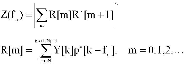
그러나, 도 3a에 도시된 바와 같이, Nogami가 제안한 알고리즘은 심볼 타이밍 오프셋에 대단히 민감하므로 도 3b와 같이 자기 상관 길이를 감소시키고 비동기 결합 길이를 증가시키는 방식을 사용함으로써 심볼 타이밍 오프셋에 대한 민감도를 감소시킬 수 있는 방안을 추가적으로 제안하였다. However, as shown in Fig. 3A, the algorithm proposed by Nogami is extremely sensitive to the symbol timing offset, thus reducing the sensitivity to the symbol timing offset by using a method of reducing the autocorrelation length and increasing the asynchronous coupling length as shown in Fig. 3B. In addition, we have proposed an alternative method.
도 3b를 살펴보면, PN 검출기(320)는 사전 약속 심볼 동안 주파수 영역에서 PN 시퀀스의 자기 상관 값을 검출한다. 상기 PN 검출기(320)에서 PN 시퀀스의 자기 상관 값을 검출한 후, 크기 발생기(330)에서 절대값의 제곱형태로 연산한 후, 제2 누적기(340)에서 누적된 다음에 최대값 인덱스 발생기(350)로 입력된다. Referring to FIG. 3B, the
상기 Zn은 하기 <수학식 2>와 같이 나타낸다.Zn is represented by Equation 2 below.

상기 수학식 2에서, Y[k]는 PRS 위치에서의 OFDM 심볼에 대한 k번째 FFT 출력 결과, p[k-fn]은 반송파 주파수 오프셋 추정치 fn에 대한 수신기의 로컬 PRS(local PRS), fn은 정수배의 반송파 주파수 오프셋 추정치, X*는 x의 공액 복소수(complex conjugate)이다.
In Equation 2, Y [k] is the k-th FFT output result of the OFDM symbol at the PRS position, p [kf n ] is the local PRS of the receiver for the carrier frequency offset estimate f n , f n Is an integer multiple of carrier frequency offset estimate, and X * is a complex conjugate of x.
그러면, 최대값 인덱스 발생기(350)는 자기 상관 값이 가장 큰 값을 가질 때의 주파수 편이 값을 초기 반송파 주파수 오프셋으로 추정한다. Then, the
반면, Taura가 제안한 알고리즘은 주파수 영역에서 PN 시퀀스를 보정하고 이를 다시 IFFT를 통해 시간 영역의 시퀀스로 변환을 시킨 뒤, 그 크기의 최대값을 최대로 하는 주파수 이동량을 초기 반송파 주파수 오프셋으로 추정하는 방식이다. 이 방식은 심볼 타이밍 오프셋에는 상당히 강한 특성을 보이나 매 주파수 오프셋 추정치에 대하여 IFFT를 수행해야 하므로 대단히 큰 하드웨어 복잡도를 요구하게 된다.Taura's algorithm, on the other hand, corrects the PN sequence in the frequency domain, converts it back to a time-domain sequence through IFFT, and estimates the frequency shift that maximizes the maximum value as the initial carrier frequency offset. to be. This method is very strong for symbol timing offsets, but requires very large hardware complexity because IFFT must be performed for every frequency offset estimate.
OFDM 수신기에서의 기존 초기 반송파 주파수 동기 기술 중 Nogami가 제안한 방식은 수신단 FFT 타이밍 오프셋이 큰 경우 자기 상관 특성이 저하되어 적용하기 어려운 문제점을 가지고 있다. 즉, FFT 타이밍 오프셋은 주파수 영역에서 선형적인 위상 회전(linear phase rotation)을 야기시키게 되며 이로 인하여 자기 상관을 취할 수 있는 부반송파수에 제약이 가해지게 되어 자기 상관 길이(correlation length)가 감소하게 된다. 자기 상관 길이가 감소하게 되는 만큼 자기 상관 값은 작아지게 되며 잡음 성분에 의해 쉽게 왜곡되어 비록 비동기 결합(noncoherent combining)을 수행하더라도 검출 성능이 열화되게 된다. 따라서, FFT 타이밍을 찾아내더라도 그 오프셋 값이 큰 경우라면 Nogami의 알고리즘은 초기 반송파 주파수 동기 검출 성능이 상당히 열화됨을 알 수 있다.
한편, 다중 경로 채널 환경하에서는 수신단 FFT 타이밍 오프셋이 작고 이전 심볼로부터의 간섭 성분이 없더라도, 타이밍 오프셋이 작은 다중 경로 성분들만이 큰 자기 상관 값을 제공하고 타이밍 오프셋이 상대적으로 큰 다중 경로 성분들은 작은 자기 상관 값을 제공한다. 따라서, 채널 지연 확산이 큰 다중 경로 채널 환경 및 단일주파수망에서는 Nogami의 알고리즘은 성능 열화량이 더욱 커지게 된다.Nogami's proposed scheme among existing early carrier frequency synchronization techniques in OFDM receivers has a problem that it is difficult to apply the autocorrelation characteristics when the receiver FFT timing offset is large. That is, the FFT timing offset causes linear phase rotation in the frequency domain, thereby limiting the number of subcarriers that can take autocorrelation, thereby reducing the correlation length. As the autocorrelation length decreases, the autocorrelation value decreases and is easily distorted by the noise component, resulting in deterioration of detection performance even if noncoherent combining is performed. Therefore, even if the FFT timing is found, if the offset value is large, the algorithm of Nogami shows that the initial carrier frequency synchronization detection performance is considerably degraded.
On the other hand, in a multipath channel environment, even if the receiver FFT timing offset is small and there is no interference component from the previous symbol, only the multipath components having a small timing offset provide a large autocorrelation value and the multipath components having a relatively large timing offset are small magnetic. Provide a correlation value. Therefore, in a multipath channel environment and a single frequency network with a large channel delay spread, Nogami's algorithm becomes more degraded in performance.
OFDM 수신기에서의 기존 초기 반송파 주파수 동기 기술 중 Taura가 제안한 방식은 수신단 FFT 타이밍 오프셋이 큰 경우에도 사전 약속 심볼을 검출할 수 있지만, 시간 영역에서의 처리를 위해서 하드웨어 복잡도가 대단히 높은 역 고속 푸리에 변환을 사용해야 하는 단점을 가지고 있다. 특히, 하나의 주파수 추정값에 대하여 역 고속 푸리에 변환 과정을 수행해야 하므로 주파수 오프셋이 큰 경우는 더욱 더 사용하기 어렵다. 또한, 시간 영역으로의 변환 이후 최대 크기값을 가지는 다중 경로 성분만을 사용하므로 다중 경로 수가 증가하고 또 비슷한 크기를 가지는 경우 성능이 상당히 열화되는 단점을 가지게 된다.Taura's proposed early carrier frequency synchronization technique in OFDM receivers can detect the pre-defined symbols even when the receiver FFT timing offset is large. It has a downside to use. In particular, since an inverse fast Fourier transform process should be performed on one frequency estimate, it is more difficult to use a large frequency offset. In addition, since only the multipath component having the maximum size value is used after the conversion to the time domain, the number of multipaths increases and the performance is considerably degraded when the number of multipaths is similar.
따라서 본 발명의 목적은 OFDM 시스템에서 수신단 FFT 타이밍 오프셋이 큰 환경에서의 자기 상관 특성의 열화를 개선하여 초기 반송파 주파수 오프셋 검출 성능을 향상시키는 반송파 주파수 동기 장치 및 방법을 제공함에 있다. Accordingly, an object of the present invention is to provide a carrier frequency synchronization apparatus and method for improving the initial carrier frequency offset detection performance by improving the deterioration of autocorrelation characteristics in an environment having a large reception FFT timing offset in an OFDM system.
본 발명의 다른 목적은 OFDM 시스템에서 채널 지연 확산이 큰 다중 경로 채널 환경 및 단일주파수망(SFN) 환경하에서도 모든 다중 경로 성분을 충분히 이용하여 자기 상관 특성을 얻을 수 있는 반송파 주파수 동기 장치 및 방법을 제공함에 있다.Another object of the present invention is to provide an apparatus and method for a carrier frequency synchronization capable of obtaining autocorrelation characteristics by fully utilizing all multipath components even in a multipath channel environment and a single frequency network (SFN) environment with a large channel delay spread in an OFDM system. In providing.
본 발명의 또 다른 목적은 주파수 영역에서만 신호 처리를 수행함으로써 기존 방식에서 높은 하드웨어 복잡도를 요구하였던 것과 달리 구현시 하드웨어 복잡도를 현저히 낮출 수 있는 반송파 주파수 동기 장치 및 방법을 제공함에 있다.Another object of the present invention is to provide a carrier frequency synchronization apparatus and method that can significantly reduce hardware complexity in implementation, unlike the conventional method, which requires high hardware complexity by performing signal processing only in the frequency domain.
본 발명의 또 다른 목적은 OFDM 시스템에서 간단한 하드웨어 구조를 사용하면서도 심볼 타이밍 오프셋 및 다중 경로 채널 환경에 강한 특성을 가지는 반송파 주파수 동기 장치 및 방법을 제공함에 있다.
상기한 바와 같은 목적을 달성하기 위한 장치는; 직교 주파수 분할 다중(OFDM: Orthogonal Frequency Division Multiplexing) 시스템에서 반송파 주파수 동기 장치에 있어서, 프레임 내의 사전 약속 심볼(PRS: Phase Reference Symbol) 위치에서의 각 OFDM 심볼을 고속푸리에변환(FFT: Fast Fourier Transform)하고, 각 FFT 심볼에 수신단에서 발생시킨 사전 약속 시퀀스(Phase Reference Sequence)를 곱한 값을 제1 누적한 후, 인접한 FFT 심볼간의 곱을 통해 차등 심볼을 획득하고, 상기 획득한 차등 심볼로부터 실수를 추출하여 제2 누적하고, 상기 제2 누적된 값을 사용하여 결정된 적어도 하나의 주파수 오프셋에 대한 메트릭을 출력하는 주파수 오프셋 추정기와, 상기 적어도 하나의 주파수 오프셋에 대한 메트릭 중 최대값을 갖는 주파수 오프셋에 대한 메트릭을 검출하고, 상기 검출된 주파수 오프셋에 대한 메트릭에 상응하는 주파수 오프셋 추정치를 반송파 주파수 오프셋 추정치로 선택하여 출력하는 최대값 인덱스 발생기를 포함한다.
상기한 바와 같은 목적을 달성하기 위한 장치는; 직교 주파수 분할 다중(OFDM: Orthogonal Frequency Division Multiplexing) 시스템에서 반송파 주파수 동기 장치에 있어서, 프레임 내의 사전 약속 심볼(PRS: Phase Reference Symbol) 위치에서의 각 OFDM 심볼을 고속푸리에변환(FFT: Fast Fourier Transform)하고, 각 FFT 심볼에 수신단에서 발생시킨 사전 약속 시퀀스(Phase Reference Sequence)를 곱한 값을 제1 누적한 후, 인접한 FFT 심볼간의 곱을 통해 차등 심볼을 획득하고, 상기 획득한 차등 심볼로부터 실수를 추출하여 제2 누적하고, 상기 제2 누적된 값을 사용하여 상기 적어도 하나의 주파수 오프셋에 대한 메트릭을 출력하는 주파수 오프셋 추정기와, 상기 적어도 하나의 주파수 오프셋에 대한 메트릭의 값이 임계값을 초과하는지 여부를 검사하고, 상기 임계값을 초과하는 값을 갖는 주파수 오프셋에 대한 메트릭을 검출하고, 상기 검출된 주파수 오프셋에 대한 매트릭에 상응하는 주파수 오프셋 추정치를 반송파 주파수 오프셋 추정치로 선택하여 출력하는 임계값 비교기를 포함한다.
상기한 바와 같은 목적을 달성하기 위한 방법은; 직교 주파수 분할 다중(OFDM: Orthogonal Frequency Division Multiplexing) 시스템에서 반송파 주파수 동기 방법에 있어서, 프레임 내의 사전 약속 심볼(PRS: Phase Reference Symbol) 위치에서의 각 OFDM 심볼을 고속푸리에변환(FFT: Fast Fourier Transform)하고, 각 FFT 심볼에 수신단에서 발생시킨 사전 약속 시퀀스(Phase Reference Sequence)를 곱한 값을 제1 누적하는 과정과, 인접한 FFT 심볼간의 곱을 통해 차등 심볼을 획득하고, 상기 획득한 차등 심볼로부터 실수를 추출하여 제2 누적하고, 상기 제2 누적된 값을 사용하여 적어도 하나의 주파수 오프셋에 대한 메트릭을 출력하는 과정과,상기 적어도 하나의 주파수 오프셋에 대한 메트릭 중 최대값을 갖는 주파수 오프셋에 대한 메트릭을 검출하고, 상기 검출된 주파수 오프셋에 대한 메트릭에 대응하는 주파수 오프셋 추정치를 반송파 주파수 오프셋 추정치로 선택하여 출력하는 과정을 포함한다.
상기한 바와 같은 목적을 달성하기 위한 방법은; 직교 주파수 분할 다중(OFDM: Orthogonal Frequency Division Multiplexing) 시스템에서 반송파 주파수 동기 방법에 있어서, 프레임 내의 사전 약속 심볼(PRS: Phase Reference Symbol) 위치에서의 OFDM 심볼을 고속푸리에변환(FFT: Fast Fourier Transform)하고, 각 FFT 심볼에 수신단에서 발생시킨 사전 약속 시퀀스(Phase Reference Sequence)를 곱한 값을 제1 누적하는 과정과, 인접한 FFT 심볼간의 곱을 통해 차등 심볼을 획득하고, 상기 획득한 차등 심볼로부터 실수를 추출하여 제2 누적하고, 상기 제2 누적된 값을 사용하여 상기 적어도 하나의 주파수 오프셋에 대한 메트릭을 출력하는 과정과, 상기 적어도 하나의 주파수 오프셋에 대한 메트릭의 값이 임계값을 초과하는지 여부를 검사하고, 상기 임계값을 초과하는 값을 갖는 주파수 오프셋에 대한 메트릭을 검출하고, 상기 검출된 주파수 오프셋에 대한 메트릭에 상응하는 주파수 오프셋 추정치를 반송파 주파수 오프셋 추정치로 선택하여 출력하는 과정을 포함한다.It is another object of the present invention to provide a carrier frequency synchronization apparatus and method having a strong characteristic in symbol timing offset and multipath channel environment while using a simple hardware structure in an OFDM system.
Apparatus for achieving the above object; In a carrier frequency synchronizer in an orthogonal frequency division multiplexing (OFDM) system, a Fast Fourier Transform (FFT) of each OFDM symbol at a position of a phase reference symbol (PRS) in a frame After accumulating a first value obtained by multiplying each FFT symbol by a phase reference sequence generated by a receiver, a differential symbol is obtained by multiplying adjacent FFT symbols, and a real number is extracted from the obtained differential symbol. A frequency offset estimator for outputting a metric for at least one frequency offset determined using the second accumulated value, the second accumulated value, and a metric for a frequency offset having a maximum value among the metrics for the at least one frequency offset Is detected and a frequency offset estimate corresponding to the metric for the detected frequency offset is obtained. Selected value to the carrier frequency offset estimate and a maximum value of an index generator for outputting.
Apparatus for achieving the above object; In a carrier frequency synchronizer in an orthogonal frequency division multiplexing (OFDM) system, a Fast Fourier Transform (FFT) of each OFDM symbol at a position of a phase reference symbol (PRS) in a frame After accumulating a first value obtained by multiplying each FFT symbol by a phase reference sequence generated by a receiver, a differential symbol is obtained by multiplying adjacent FFT symbols, and a real number is extracted from the obtained differential symbol. A second offset and a frequency offset estimator for outputting a metric for the at least one frequency offset using the second accumulated value and whether the value of the metric for the at least one frequency offset exceeds a threshold Examine and detect a metric for a frequency offset having a value above the threshold, and detecting the Selecting the frequency offset estimate that corresponds to the metric for the frequency offset in the carrier frequency offset estimate and a threshold comparator for outputting.
The method for achieving the object as described above; In a carrier frequency synchronization method in an orthogonal frequency division multiplexing (OFDM) system, a fast Fourier transform (FFT) of each OFDM symbol at a position of a phase reference symbol (PRS) in a frame The first symbol is obtained by multiplying each FFT symbol by a product of a phase reference sequence generated at the receiving end, obtaining a differential symbol by multiplying adjacent FFT symbols, and extracting a real number from the obtained differential symbol. And accumulating a second cumulative value and outputting a metric for at least one frequency offset using the second accumulated value, and detecting a metric for a frequency offset having a maximum value among the metrics for the at least one frequency offset. And a frequency offset estimate corresponding to the metric for the detected frequency offset. Selecting and outputting the number offset estimate.
The method for achieving the object as described above; In a carrier frequency synchronization method in an orthogonal frequency division multiplexing (OFDM) system, a fast Fourier transform (FFT) is performed on an OFDM symbol at a position of a phase reference symbol (PRS) in a frame. The process of first accumulating a value obtained by multiplying each FFT symbol by a phase reference sequence generated by a receiver, obtaining a differential symbol through a product of adjacent FFT symbols, and extracting a real number from the obtained differential symbol Outputting a metric for the at least one frequency offset using a second accumulated value, and using the second accumulated value, checking whether a value of the metric for the at least one frequency offset exceeds a threshold; Detect a metric for a frequency offset with a value above the threshold, and detect the detected frequency error. Selecting the frequency offset estimate that corresponds to the metric for a set of a carrier frequency offset estimate comprises the step of outputting.
상기한 바와 같은 목적을 달성하기 위한 방법은; 직교 주파수 분할 다중(OFDM: Orthogonal Frequency Division Multiplexing) 시스템에서 반송파 주파수 동기 방법에 있어서, 프레임 내의 사전 약속 심볼(PRS: Phase Reference Symbol) 위치에서의 각 OFDM 심볼을 고속푸리에변환(FFT: Fast Fourier Transform)하고, 각 FFT 심볼에 수신단에서 발생시킨 사전 약속 시퀀스(Phase Reference Sequence)를 곱한 값을 제1 누적한 후, 인접한 FFT 심볼간의 곱을 통해 차등 심볼을 획득하고, 상기 획득한 차등 심볼로부터 실수를 추출하여 제2 누적하고, 상기 제2 누적된 값을 사용하여 적어도 하나의 주파수 오프셋에 대한 메트릭을 출력하는 과정과, 상기 적어도 하나의 주파수 오프셋에 대한 메트릭을 사용하여 마지막 주파수 인덱스를 판단하는 과정과, 상기 마지막 주파수 인덱스를 판단한 경우, 각 주파수 인덱스에 따라 저장된 주파수 오프셋에 대한 메트릭들 중 최대값을 갖는 주파수 오프셋에 대한 메트릭을 검출하고, 상기 검출된 주파수 오프셋에 대한 메트릭에 상응하는 주파수 인덱스를 반송파 주파수 오프셋 추정치로 선택하여 출력하는 과정을 포함한다.
상기한 바와 같은 목적을 달성하기 위한 방법은; 직교 주파수 분할 다중(OFDM: Orthogonal Frequency Division Multiplexing) 시스템에서, 반송파 주파수 동기 방법에 있어서, 프레임 내의 사전 약속 심볼(PRS: Phase Reference Symbol) 위치에서의 각 OFDM 심볼을 고속푸리에변환(FFT: Fast Fourier Transform)하고, 각 FFT 심볼에 수신단에서 발생시킨 사전 약속 시퀀스(Phase Reference Sequence)를 곱한 값에 대해 제1누적 절차를 수행하는 과정과, 인접한 FFT 심볼간의 곱을 통해 차등 심볼을 획득하는 과정과, 상기 획득한 차등 심볼로부터 실수를 추출하여 누적하는 제2누적 절차를 수행하는 과정과, 상기 제2누적 절차 수행 결과에 따라 적어도 하나의 주파수 오프셋에 대한 메트릭의 값을 출력하는 과정을 포함한다.The method for achieving the object as described above; In a carrier frequency synchronization method in an orthogonal frequency division multiplexing (OFDM) system, a fast Fourier transform (FFT) of each OFDM symbol at a position of a phase reference symbol (PRS) in a frame After accumulating a first value obtained by multiplying each FFT symbol by a phase reference sequence generated by a receiver, a differential symbol is obtained by multiplying adjacent FFT symbols, and a real number is extracted from the obtained differential symbol. Outputting a metric for at least one frequency offset using a second accumulated value and the second accumulated value, determining a final frequency index using the metric for the at least one frequency offset, and If you have determined the last frequency index, the metric for the stored frequency offset according to each frequency index. Detecting a metric for a frequency offset having a maximum value among the Ricks, and selecting and outputting a frequency index corresponding to the metric for the detected frequency offset as a carrier frequency offset estimate.
The method for achieving the object as described above; In an Orthogonal Frequency Division Multiplexing (OFDM) system, in a carrier frequency synchronization method, a Fast Fourier Transform (FFT) of each OFDM symbol at a position of a Phase Reference Symbol (PRS) in a frame Performing a first cumulative procedure on a value obtained by multiplying each FFT symbol by a phase reference sequence generated at a receiving end, obtaining a differential symbol by multiplying adjacent FFT symbols, and obtaining Performing a second cumulative procedure of extracting and accumulating a real number from one differential symbol; and outputting a metric value for at least one frequency offset according to a result of performing the second cumulative procedure.
삭제delete
삭제delete
삭제delete
하기에서 본 발명을 설명함에 있어 관련된 공지 기능 또는 구성에 대한 구체적인 설명이 본 발명의 요지를 불필요하게 흐릴 수 있다고 판단되는 경우에는 그 상세한 설명을 생략할 것이다. 그리고 후술되는 용어들은 본 발명에서의 기능을 고려하여 정의된 용어들로서 이는 사용자, 운용자의 의도 또는 관례 등에 따라 달라질 수 있다. 그러므로 그 정의는 본 명세서 전반에 걸친 내용을 토대로 내려져야 할 것이다.In the following description of the present invention, detailed descriptions of well-known functions or configurations will be omitted if it is determined that the detailed description of the present invention may unnecessarily obscure the subject matter of the present invention. The following terms are defined in consideration of the functions of the present invention, and may be changed according to the intentions or customs of the user, the operator, and the like. Therefore, the definition should be based on the contents throughout this specification.
OFDM 시스템에서의 초기 반송파 주파수 오프셋 추정기는 도 4a와 같이 디지털 영역에서 보정하는 경우와 도 4b에서와 같이 아날로그 영역에서 보정하는 경우로 구분될 수 있다. An initial carrier frequency offset estimator in an OFDM system may be classified into a case of correcting in the digital domain as shown in FIG. 4A and a case of correcting in the analog domain as shown in FIG. 4B.
도 4a를 살펴보면, RF 수신부(420)는 안테나(410)를 통해 수신된 OFDM 신호를 기저대역 신호로 전환하여 ADC(430)로 출력한다. 상기 ADC(430)은 송신단에서 IFFT를 통해 시간 영역으로 변환되어 전송된 아날로그 형태의 신호를 디지털 신호로 변환하여 주파수 오프셋 보정기(440)로 출력한다. 상기 주파수 오프셋 보정기(440)는 송신단과 수신단간의 동조기 특성 차이로 인해 발생되는 수신 데이터의 주파수 오프셋을 후술되는 주파수 오프셋 추정기(460)에 의해서 출력된 주파수 오프셋 추정값에 따라 보정한다. FFT(450)는 수신된 시간 영역의 수신 데이터를 주파수 영역으로 변환한다. 주파수 오프셋 추정기(460)는 대부분 상기 FFT(450)에 의하여 주파수 영역으로 전환된 신호를 사용하여 주파수 오프셋을 추정하고, 추정된 주파수 오프셋 값은 주파수 오프셋 보정기(440)에 의해서 보상된다.Referring to FIG. 4A, the
반면에, 도 4b의 경우, 주파수 오프셋 추정기(460)는 아날로그 영역을 보정하기 위해서 FFT(450)에 의하여 주파수 영역으로 전환된 신호를 사용하여 주파수 오프셋을 추정하고, 추정된 주파수 오프셋 값은 아날로그 신호 변환기(470)를 통해 아날로그 신호로 변환하여 RF 수신부(420)로 전달된다. 상기 RF 수신부(420)에서는 오실레이터(oscillator)의 주파수 조절과 믹서(Mixer)(도면에 기재되지 않음)에서 반송파 주파수 오프셋 보정을 수행한다. On the other hand, in FIG. 4B, the frequency offset
본 발명에서는 초기 반송파 주파수 동기화를 위하여 사전 약속 심볼을 전송하는 OFDM 시스템을 가정한다. 사전 약속 심볼을 전송하는 OFDM 시스템의 일례로서는 유럽형 디지털 오디오 방송 규격안인 DAB 또는 유럽형 디지털 비디오 방송 규격안인 DVB-T 및 DVB-H 등을 들 수 있다. DAB 시스템에서는 PRS(Phase Reference Symbol)라는 사전 약속 심볼을 전송하며 DVB-T 또는 DVB-H에서는 파일럿 캐리어(pilot carrier)에 PRBS(Pseudo-Random Binary Sequence)라는 사전 약속 심볼을 전송한다. 언급한 OFDM 기반의 시스템에서는 모두 주파수 영역에서 자기 상관 특성이 우수한 시퀀스를 모든 부반송파 또는 파일럿 캐리어에 전송함을 특징으로 한다. 하기부터는 DAB 시스템을 가정하여 본 발명의 구성을 설명하기로 하지만, 본 발명이 자기 상관 특성을 이용할 수 있는 사전 약속 심볼이 전송되는 OFDM 시스템에 일반적으로 적용 가능함을 상기해야 한다.In the present invention, it is assumed that the OFDM system that transmits the advance symbol for the initial carrier frequency synchronization. An example of an OFDM system for transmitting an advanced symbol is DAB, which is a European digital audio broadcasting standard, or DVB-T, DVB-H, which is a European digital video broadcasting standard. A DAB system transmits an advanced symbol called PRS (Phase Reference Symbol) and a DVB-T or DVB-H transmits a PBS (Pseudo-Random Binary Sequence) to a pilot carrier. In the OFDM-based system mentioned above, all sequences having excellent autocorrelation in the frequency domain are transmitted to all subcarriers or pilot carriers. Hereinafter, a configuration of the present invention will be described on the assumption of a DAB system, but it should be recalled that the present invention is generally applicable to an OFDM system in which a predetermined symbol that can use autocorrelation characteristics is transmitted.
도 5는 DAB 시스템의 프레임 구조를 도시한 것으로, 심볼 및 반송파 동기화 과정을 위하여 프레임에는 NULL 심볼(510) 및 PRS(phase reference symbol)(520)가 포함되어 전송된다. 동기화 심볼 이후에는 제어 신호를 전송하는 FIC(Fast Information Channel)(530a-530c)가 전송되고 그 뒤로 데이터 채널인 MSC(Main Service Channel)가 전송된다. DAB 시스템에 있어서는 사용되는 사전 약속 심볼은 PRS(520)로서 주파수 영역의 모든 부반송파에 일련의 약속된 시퀀스를 전송한다. 그 시퀀스의 자기 상관(autocorrelation) 특성은 도 2에서 도시한 바와 같이 시퀀스의 위상차가 0인 경우 큰 자기 상관 값을 가지며, 시퀀스의 위상차가 0이 아닌 경우는 작은 자기 상관 값을 가지게 된다.FIG. 5 illustrates a frame structure of a DAB system. A
DAB 시스템에 있어서의 동기화 과정은 먼저 NULL 심볼(510)을 검출함으로써 프레임 동기화를 수행하며 이 과정으로부터 대략적인 OFDM 심볼의 위치도 함께 검출한다. NULL 심볼(510) 이후에 전송되는 PRS(520)는 상기 언급한 바와 같이 사전 약속된 심볼로 초기 반송파 주파수 동기화 및 심볼 타이밍 동기화 등에 사용될 수 있다. 본 발명에서의 초기 반송파 주파수 동기화는 도 2에서 도시한 것과 같이 우수한 PRS의 자기 상관 특성을 이용하며, PRS에 전송되는 약속된 시퀀스의 위상차가 주파수 오프셋에 비례하는 성질을 사용한다. 즉, 자기 상관값이 최대가 되는 시퀀스의 위상차 값을 부반송파 간격의 정수배에 해당되는 주파수 오프셋으로 추정하게 되는 것이다.The synchronization process in the DAB system performs frame synchronization by first detecting the
도 6a는 본 발명의 실시 예에 따른 OFDM 시스템에서 초기 반송파 주파수 동기 장치를 도시한 도면이다.
OFDM 시스템에서 초기 반송파 주파수 동기 장치는 저장부(도면에 기재하지 않음), PN 검출기(610), 제 1 누적기(620), 차등 심볼 검출기(630), 실수 검출기40), 제 2 누적기(650), 최대값 인덱스 발생기(660) 및 임계값 비교기(670)를 포함한다. 수신 신호에 대한 FFT 처리 과정에서 발생될 수 있는 타이밍 오프셋은 FFT 출력 신호 값을 선형적으로 회전시키게 된다. 그러므로 자기 상관을 취할 경우 자기 상관값의 크기는 심볼 타이밍 오프셋에 비례하여 감소하게 된다. 이와 같은 자기 상관 값의 감소는 곧 주파수 오프셋 검출 성능의 저하로 나타나게 된다. 본 발명에서는 가까운 부반송파들 사이에서는 심볼 타이밍 오프셋으로 인하여 발생되는 위상 회전 정도는 매우 작다는 점을 이용하여 차등 심볼을 이용하는 방식을 제공한다.6A illustrates an initial carrier frequency synchronization device in an OFDM system according to an embodiment of the present invention.
In an OFDM system, an initial carrier frequency synchronization device includes a storage unit (not shown), a
본 발명의 실시 예에 따른 OFDM 시스템에서 초기 반송파 주파수 동기 장치를 설명하면, 상기 저장부는 사전 약속 심볼 위치에서의 OFDM 심볼을 수신하여 FFT한 결과를 저장한다. 상기 PN 검출기(610)는 프레임 내의 PRS 위치에서의 FFT 출력 신호를 입력으로 하여 수신단에서 발생시킨 PRS에 의해 곱해지는 PRS decover를 통해 데이터 변조되는 특성을 제거한다. 상기 제 1 누적기(620)는 상기 PN 검출기(610)의 출력을 입력받아 누적한 후, 차등 심볼 검출기(630)로 출력한다. 상기 차등 심볼 검출기(630)는 인접한 심볼간의 곱을 통해 차등 심볼을 얻어낸다. 제 1 누적기(620)에서는 누적 구간이 증가할수록 차등 심볼 검출기(630)의 입력 신호의 신호 품질을 향상시켜 더욱 낮은 신호대잡음비 환경하에서도 검출 성능을 향상시킨다. 그러나 심볼 타이밍 오프셋이 있는 경우 누적 구간이 증가할수록 성능 감소가 발생하므로 적절한 최적의 누적 구간을 찾는 것이 중요하다. 그러므로 제 1 누적기(620)는 경우에 따라서 필요하지 않을 수도 있음을 유의하여야 한다. 특히, 본 발명에서 사용하는 누적 길이는 기존 방식에 비해 상당히 작게 설정함으로써 심볼 타이밍 오프셋에 의한 성능 감소 효과를 줄일 수 있다. 이와 같이 차등 검출된 심볼은 그 값이 복소수일지라도 실수부가 허수부에 비해 상당히 큰 값을 가지며 또한 실수부가 대부분 양의 값을 가지게 된다. 따라서, 실수 검출부(640)는 차등 심볼의 실수부만을 추출하고 제 2 누적기(650)를 통해서 누적함으로써 잡음에 대한 성능 향상 효과를 얻을 수 있다. 따라서, 주파수 오프셋에 대한 메트릭 Z(fn)은 하기 <수학식 3> 과 같이 표현된다.In an OFDM system according to an embodiment of the present invention, an initial carrier frequency synchronization apparatus is described. The storage unit stores an FFT by receiving an OFDM symbol at a predetermined symbol position. The

상기 수학식 3에서, Y[k]는 PRS 위치에서의 OFDM 심볼에 대한 k번째 FFT 출력 결과, p[k-fn]은 반송파 주파수 오프셋 추정치 fn에 대한 수신기의 로컬 PRS(local PRS), fn은 정수배의 반송파 주파수 오프셋 추정치, X*는 x의 공액 복소수이다.In Equation 3, Y [k] is the k-th FFT output result of the OFDM symbol at the PRS position, p [kf n ] is the local PRS of the receiver for the carrier frequency offset estimate f n , f n Is an integer multiple of carrier frequency offset estimate, and X * is a conjugate complex number of x.
한편, 제 1 누적기(620)의 누적 길이에 비해 심볼 타이밍 오프셋이 큰 경우 차등 심볼의 실수부가 허수부에 비해서 그 크기가 크지 않게 되므로, 이 때는 도 6b와 같이 크기 발생기(645)가 차등 심볼의 크기 성분을 제 2 누적기(650)로 입력한다. 따라서, 주파수 오프셋에 대한 메트릭 Z(fn)은 하기 <수학식 4> 과 같이 표현된다.On the other hand, when the symbol timing offset is larger than the cumulative length of the
여기서 p는 0보다 큰 정수값을 가지고, Y[k]는 PRS 위치에서의 OFDM 심볼에 대한 k번째 FFT 출력 결과, p[k-fn]은 반송파 주파수 오프셋 추정치 fn에 대한 수신기의 로컬 PRS(local PRS), fn은 정수배의 반송파 주파수 오프셋 추정치, X*는 x의 공액 복소수이다.Where p has an integer value greater than 0, Y [k] is the k-th FFT output for the OFDM symbol at the PRS location, and p [kf n ] is the receiver's local PRS (local) for the carrier frequency offset estimate f n . PRS), f n is an integer multiple of carrier frequency offset estimate, and X * is a conjugate complex number of x.
상기 <수학식 3> 및 <수학식 4>는 각각의 정수배의 반송파 주파수 오프셋 추정치 fn에 대한 메트릭(metric)을 의미하며, 최종적으로 최대값 인덱스 발생기(660)는 모든 주파수 오프셋 추정치에 대해서 상기 기술한 단계에 의해 얻어낸 메트릭 값들을 서로 비교하여 그 값이 최대가 되는 경우의 주파수 오프셋 추정치를 반송파 주파수 오프셋 값으로 선택한다. 따라서, 최대값 인덱스 발생기(660)의 출력은 하기 <수학식 5>과 같이 표현될 수 있다.Equations 3 and 4 denote metrics for each carrier frequency offset estimate fn of an integer multiple, and finally, the maximum

한편, 상기 <수학식> 5의 최대값 인덱스 검출기의 대안으로 임계값 비교기 (670)을 사용할 수 있는데, 상기 임계값 비교기(670)에서는 각각의 반송파 주파수 오프셋 추정치 fn에 대하여 <수학식 3> 또는 <수학식 4>를 통해 얻은 메트릭 값이 특정 임계값을 초과하는지를 검사하고, 만약 임계값을 초과하는 반송파 주파수 오프셋 추정치가 있으면 그 값을 정수배의 반송파 주파수 오프셋 값으로 결정한다.Alternatively, the
본 발명의 실시 예에 따른 직교주파수다중 방식의 무선통신 시스템에서 반송파 주파수 동기 방법은 도 7을 참조하여 설명하기로 한다. 도 7은 상기 <수학식 5>에서 제시한 바와 같이 최대값을 선택하는 주파수 오프셋 검출 방식을 적용한 흐름도이다. In the orthogonal frequency multiplex wireless communication system according to an exemplary embodiment of the present invention, a carrier frequency synchronization method will be described with reference to FIG. 7. 7 is a flowchart applying a frequency offset detection method of selecting the maximum value as shown in Equation (5).
상기 저장부는 701 단계에서 사전 약속 심볼 위치에서의 OFDM 심볼을 수신하여 FFT한 결과를 저장한다. 이후, 주파수 오프셋 추정기(460)는 703 단계에서 저장되어 있거나 또는 발생기에 의해 사전 약속 시퀀스를 주파수 인덱스에 따라 발생한다.In
상기 주파수 오프셋 추정기(460)는 705 단계에서 도 6a 및 도 6b에 의한 초기 주파수 추정용 메트릭인 Zn을 계산한다. 이후, 상기 최대값 인덱스 발생기(660)는 707 단계에서 상기 Zn을 통해서 검사하고자 하는 인덱스 범위의 끝인가를 판단한다. 만약, 인덱스의 끝이 아닌 경우 709 단계에서 상기 주파수 오프셋 추정기(460)는 주파수 인덱스를 추정 주파수 범위 내에서 변경한다. The frequency offset
그러나 검사하고자 하는 인덱스의 끝인 경우 상기 최대값 인덱스 발생기(660)는 711 단계에서 주파수 인덱스에 따라 저장된 Zn 값들 중 최대값을 가지는 주파수 인덱스를 초기 반송파 주파수 오프셋 값으로 결정하여 출력한다.However, at the end of the index to be examined, the
이후, 주파수 오프셋 보정기(440)는 713 단계에서 상기 주파수 오프셋 추정기(460)에 의하여 추정된 주파수 오프셋을 보정한다.In
본 발명의 다른 실시 예에 따른 직교주파수다중 방식의 무선통신 시스템에서 반송파 주파수 동기 방법은 도 8을 참조하여 설명하기로 한다. 도 8은 임계값 비교에 근거하는 주파수 오프셋 검출 방식을 적용한 흐름도이다. In the orthogonal frequency multiplex wireless communication system according to another embodiment of the present invention, a carrier frequency synchronization method will be described with reference to FIG. 8. 8 is a flowchart applying a frequency offset detection method based on a threshold comparison.
상기 저장부는 801 단계에서 사전 약속 심볼 위치에서의 OFDM 심볼을 수신하여 FFT한 결과를 저장한다. 이후, 상기 주파수 오프셋 추정기(340)는 803 단계에서 저장되어 있거나 또는 발생기에 의해 사전 약속 시퀀스를 주파수 인덱스에 따라 발생한다.In
상기 주파수 오프셋 추정기(460)는 805 단계에서 도 6a 및 도 6b에 의한 초기 주파수 추정용 메트릭인 Zn을 계산한다. 이후, 상기 임계값 비교기(670)는 807 단계에서 상기 Zn이 임계값 보다 큰 가를 판단한다. 만약, Zn이 임계값 보다 작거나 같은 경우 809 단계에서 상기 임계값 비교기(670)는 주파수 인덱스를 추정 주파수 범위 내에서 변경한다.The frequency offset
그러나 Zn이 임계값 보다 큰 경우 상기 임계값 비교기(670)는 811 단계에서 주파수 인덱스의 값을 초기 반송파 주파수 오프셋 값으로 결정하여 출력한다.However, if Zn is greater than the threshold, the
이후, 주파수 오프셋 보정기(440)는 813 단계에서 상기 주파수 오프셋 추정기(460)에 의하여 추정된 주파수 오프셋을 보정한다. In
도 9는 본 발명의 성능을 제시한 것으로, 반송파 주파수 오프셋이 잘못 검출될 확률을 심볼 타이밍 오프셋에 대하여 도시한 것이다. 또한, 성능 비교를 위하여 본 발명에서 제시한 방식과 기존의 방식을 상호간에 비교하여 도시하였다. 도 9에서 확인할 수 있는 바와 같이, 본 발명의 초기 반송파 주파수 동기 방식이 기존 방식에 비해 수신단 FFT 타이밍 오프셋 큰 환경에서도 자기 상관 특성의 열화를 개선하여 초기 반송파 주파수 오프셋 검출 성능을 크게 향상시키는 효과를 얻을 수 있음을 확인할 수 있다. 9 illustrates the performance of the present invention and illustrates the probability of a carrier frequency offset being incorrectly detected with respect to the symbol timing offset. Also, for performance comparison, the schemes presented in the present invention are compared with the conventional schemes. As can be seen in FIG. 9, the initial carrier frequency synchronization method of the present invention improves the initial carrier frequency offset detection performance by improving the deterioration of the autocorrelation characteristics even in an environment where the receiver FFT timing offset is larger than the conventional method. It can be confirmed that.
삭제delete
삭제delete
삭제delete
삭제delete
이상에서 상세히 설명한 바와 같이 동작하는 본 발명에 있어서, 개시되는 발명 중 대표적인 것에 의하여 얻어지는 효과를 간단히 설명하면 다음과 같다.In the present invention that operates as described in detail above, the effects obtained by the representative ones of the disclosed inventions will be briefly described as follows.
본 발명은, 초기 반송파 주파수 동기 방식이 기존 방식에 비해 수신단 FFT 타이밍 오프셋 큰 환경에서도 자기 상관 특성의 열화를 개선하여 초기 반송파 주파수 오프셋 검출 성능을 크게 향상시키는 효과가 있다. The present invention has an effect of greatly improving the initial carrier frequency offset detection performance by improving the deterioration of the autocorrelation characteristics even in an environment where the initial carrier frequency synchronization scheme has a larger receiving end FFT timing offset than the conventional scheme.
또한 본 발명은, 차등 심볼 검출 구조를 사용하므로 채널 지연 확산이 큰 다중 경로 채널 환경에서도 모든 다중 경로 성분을 기존 방식에 비해서 충분히 이용하는 자기 상관 특성을 얻을 수 있으므로 초기 반송파 주파수 오프셋 검출 성능을 향상시키는 효과가 있다. In addition, since the present invention uses a differential symbol detection structure, even in a multipath channel environment having a large channel delay spread, an autocorrelation property that fully utilizes all multipath components as compared to the conventional method can be obtained, thereby improving initial carrier frequency offset detection performance. There is.
또한 본 발명은 주파수 영역에서만 신호 처리를 수행함으로써 기존 방식에서 높은 하드웨어 복잡도를 요구하였던 것과 달리 구현시 하드웨어 복잡도를 현저히 낮추는 효과를 있다. In addition, the present invention has the effect of significantly lowering the hardware complexity at the time of implementation, unlike the conventional method, which requires high hardware complexity by performing signal processing only in the frequency domain.
마지막으로 기존에는 FFT 타이밍 오프셋이 충분히 작도록 프레임 또는 타이밍 동기화를 수행하였으나 본 발명을 통해서 대략적인 프레임/타이밍 동기화가 가능해지도록 하는 효과가 있다.Lastly, although frame or timing synchronization is performed so that the FFT timing offset is sufficiently small, the present invention has an effect of enabling an approximate frame / timing synchronization.
Claims (43)


Priority Applications (6)
| Application Number | Priority Date | Filing Date | Title |
|---|---|---|---|
| KR1020050115153A KR101026469B1 (en) | 2005-11-29 | 2005-11-29 | Carrier frequency synchronization apparatus and method in ofdm system |
| US11/605,484 US7693039B2 (en) | 2005-11-29 | 2006-11-29 | Apparatus and method for carrier frequency synchronization in an OFDM system |
| EP06024722.8A EP1791314B1 (en) | 2005-11-29 | 2006-11-29 | Apparatus and method for carrier frequency synchronization in an OFDM system |
| CN2006800519680A CN101336522B (en) | 2005-11-29 | 2006-11-29 | Apparatus and method for carrier frequency synchronization in an OFDM system |
| PCT/KR2006/005103 WO2007064151A1 (en) | 2005-11-29 | 2006-11-29 | Apparatus and method for carrier frequency synchronization in an ofdm system |
| JP2008543198A JP4638944B2 (en) | 2005-11-29 | 2006-11-29 | Carrier frequency synchronization apparatus and method in orthogonal frequency division multiplexing system |
Applications Claiming Priority (1)
| Application Number | Priority Date | Filing Date | Title |
|---|---|---|---|
| KR1020050115153A KR101026469B1 (en) | 2005-11-29 | 2005-11-29 | Carrier frequency synchronization apparatus and method in ofdm system |
Publications (2)
| Publication Number | Publication Date |
|---|---|
| KR20070056480A KR20070056480A (en) | 2007-06-04 |
| KR101026469B1 true KR101026469B1 (en) | 2011-04-01 |
Family
ID=37889657
Family Applications (1)
| Application Number | Title | Priority Date | Filing Date |
|---|---|---|---|
| KR1020050115153A KR101026469B1 (en) | 2005-11-29 | 2005-11-29 | Carrier frequency synchronization apparatus and method in ofdm system |
Country Status (6)
| Country | Link |
|---|---|
| US (1) | US7693039B2 (en) |
| EP (1) | EP1791314B1 (en) |
| JP (1) | JP4638944B2 (en) |
| KR (1) | KR101026469B1 (en) |
| CN (1) | CN101336522B (en) |
| WO (1) | WO2007064151A1 (en) |
Families Citing this family (42)
| Publication number | Priority date | Publication date | Assignee | Title |
|---|---|---|---|---|
| US7529179B1 (en) * | 2005-02-11 | 2009-05-05 | Marvell International Ltd. | Joint maximum likelihood estimation of integer carrier frequency offset and channel in OFDM systems |
| US8457178B2 (en) * | 2007-03-26 | 2013-06-04 | Qualcomm Incorporated | Frequency offset estimator |
| US7817736B2 (en) * | 2007-06-29 | 2010-10-19 | Texas Instruments Incorporated | Correcting for carrier frequency offset in multi-carrier communication systems |
| US7801020B2 (en) * | 2007-08-29 | 2010-09-21 | Intel Corporation | Mobile channel estimation algorithm for DVB-H COFDM demodulator |
| US8045628B2 (en) * | 2007-10-18 | 2011-10-25 | Nokia Corporation | Digital video broadcast service discovery |
| US7961816B2 (en) * | 2007-11-28 | 2011-06-14 | Industrial Technology Research Institute | Device for and method of signal synchronization in a communication system |
| EP2099187B1 (en) * | 2008-03-07 | 2011-05-25 | Sony Corporation | Wireless system using a new type of preamble for a burst frame |
| US7944999B2 (en) | 2008-04-04 | 2011-05-17 | Newport Media, Inc. | Robust fine frequency and time estimation in mobile multimedia multicast system receivers |
| CN101267423B (en) * | 2008-05-09 | 2011-07-20 | 哈尔滨工业大学 | Method for estimating clock frequency deviation based on fraction Fourier domain in ultra-broadband system |
| US8040790B2 (en) * | 2008-08-29 | 2011-10-18 | Indian Institute Of Technology | Low complexity bandwidth efficient carrier frequency offset estimation technique for OFDMA uplink transmissions |
| US9057606B2 (en) | 2009-09-10 | 2015-06-16 | Nextnav, Llc | Wide area positioning system |
| CN102204396B (en) | 2008-09-10 | 2014-08-06 | 科姆拉布斯公司 | Wide area positioning system |
| US9035829B2 (en) | 2008-09-10 | 2015-05-19 | Nextnav, Llc | Wide area positioning systems and methods |
| US9119165B2 (en) | 2009-09-10 | 2015-08-25 | Nextnav, Llc | Coding in a wide area positioning system (WAPS) |
| CN102334320A (en) * | 2009-04-27 | 2012-01-25 | 华为技术有限公司 | Positioning reference signals |
| CN101616360B (en) | 2009-07-24 | 2012-05-09 | 中兴通讯股份有限公司 | Method and system for sending positioning reference signal |
| US8289374B2 (en) * | 2009-08-25 | 2012-10-16 | Disney Enterprises, Inc. | Method and system for encoding and transmitting high definition 3-D multimedia content |
| TWI423628B (en) * | 2009-09-02 | 2014-01-11 | Univ Nat Taiwan | Receivers and methods of carrier frequency offset detection |
| KR20110027626A (en) * | 2009-09-09 | 2011-03-16 | 주식회사 팬택 | Method for transmission and receiving signal in communication system |
| US9291712B2 (en) | 2009-09-10 | 2016-03-22 | Nextnav, Llc | Cell organization and transmission schemes in a wide area positioning system (WAPS) |
| US9372266B2 (en) | 2009-09-10 | 2016-06-21 | Nextnav, Llc | Cell organization and transmission schemes in a wide area positioning system (WAPS) |
| TWI403135B (en) * | 2009-10-22 | 2013-07-21 | Univ Nat Taiwan | Transmitter, receiver and method for detecting and compensating the carrier frequency offset |
| US8559567B1 (en) * | 2010-02-05 | 2013-10-15 | Marvell International Ltd. | Channel estimation using reduced-complexity cascaded one-dimensional filtering |
| US8848844B2 (en) * | 2010-09-17 | 2014-09-30 | Telefonaktiebolaget L M Ericsson (Publ) | Receiver node and a method therein for compensating frequency offset |
| US8611471B2 (en) | 2011-03-31 | 2013-12-17 | Saankhya Labs Pvt. Ltd. | Method and system for reliable CFO and STO estimation in the presence of tuner induced impairment |
| US9176217B2 (en) | 2011-08-02 | 2015-11-03 | Nextnav, Llc | Cell organization and transmission schemes in a wide area positioning system (WAPS) |
| CN104583802A (en) | 2012-06-05 | 2015-04-29 | 耐克斯特纳威公司 | Systems and methods for location positioning of user device |
| US9286490B2 (en) | 2013-09-10 | 2016-03-15 | Nextnav, Llc | Systems and methods for providing conditional access to transmitted information |
| US9390279B2 (en) | 2012-09-11 | 2016-07-12 | Nextnav, Llc | Systems and methods for providing conditional access to transmitted information |
| KR101637940B1 (en) * | 2015-02-25 | 2016-07-11 | (주)에프씨아이 | Method for Synchronizing OFDM Sysbols |
| CN105004913A (en) * | 2015-07-21 | 2015-10-28 | 黎文安 | Real-time tracking method for alternating current sampling frequency of electric power system |
| CN106375257B (en) * | 2016-08-29 | 2019-03-29 | 电子科技大学 | A kind of multistage frequency deviation estimating method based on FFT |
| CN107483078B (en) * | 2017-07-26 | 2019-08-09 | 北京遥测技术研究所 | A kind of ship VDES system ASM system reception frequency offset estimation implementation method |
| US10218549B1 (en) | 2018-01-24 | 2019-02-26 | National Instruments Corporation | Wireless radio receiver that performs adaptive phase tracking |
| US10218548B1 (en) * | 2018-01-24 | 2019-02-26 | National Instruments Corporation | Wireless radio receiver that performs adaptive phase tracking |
| CN110474860B (en) * | 2018-05-11 | 2021-06-04 | 维沃移动通信有限公司 | OFDM baseband signal generation method and device |
| EP3591919A1 (en) * | 2018-07-05 | 2020-01-08 | Nxp B.V. | Signal communication with decoding window |
| CN110708265B (en) * | 2018-07-09 | 2022-07-12 | 上海数字电视国家工程研究中心有限公司 | Frequency offset estimation system and method |
| US11757535B2 (en) * | 2020-06-23 | 2023-09-12 | Infinera Corporation | Data synchronization in optical networks and devices |
| KR102376492B1 (en) | 2020-08-05 | 2022-03-21 | 아스텔 주식회사 | Fast Fourier transform device and method using real valued as input |
| CN113992255B (en) * | 2021-12-27 | 2022-04-19 | 南京典格通信科技有限公司 | Antenna calibration method and device based on system frame number |
| CN115174336B (en) * | 2022-07-20 | 2023-10-31 | 成都中科微信息技术研究院有限公司 | Frequency offset estimation method, medium and device of DVB-RCS2 system |
Citations (2)
| Publication number | Priority date | Publication date | Assignee | Title |
|---|---|---|---|---|
| EP1195961A2 (en) | 2000-09-29 | 2002-04-10 | Samsung Electronics Co., Ltd. | Frequency offset correction in multicarrier receivers |
| KR20050075869A (en) * | 2004-01-16 | 2005-07-25 | 삼성전자주식회사 | Coarse frequency synchronization method and apparatus in ofdm system |
Family Cites Families (7)
| Publication number | Priority date | Publication date | Assignee | Title |
|---|---|---|---|---|
| KR100263372B1 (en) * | 1997-11-29 | 2000-08-01 | 전주범 | Coarse frequency acquistion method and thereof appratus for orthogonal frequency division multiplexing systems |
| JP3019072B2 (en) * | 1998-08-24 | 2000-03-13 | 松下電器産業株式会社 | Frequency error estimating apparatus, receiving apparatus using the same, relay apparatus, and wireless communication system |
| KR100335443B1 (en) * | 1999-06-15 | 2002-05-04 | 윤종용 | Symbol timing and frequency synchronizing device for OFDM signals and method thereof |
| JP2001313628A (en) * | 2000-04-28 | 2001-11-09 | Sony Corp | Ofdm receiver and ofm reception method |
| KR100418975B1 (en) * | 2001-06-12 | 2004-02-14 | 전자부품연구원 | A synchronization apparatus and method of coarse frequency offset in digital audio broadcasting system |
| KR100510861B1 (en) * | 2003-01-18 | 2005-08-31 | 디지피아(주) | Training signal determining method in OFDM system and apparatus and method for receiving OFDM signal using the training signal |
| US7746760B2 (en) * | 2004-01-08 | 2010-06-29 | Qualcomm Incorporated | Frequency error estimation and frame synchronization in an OFDM system |
-
2005
- 2005-11-29 KR KR1020050115153A patent/KR101026469B1/en not_active IP Right Cessation
-
2006
- 2006-11-29 WO PCT/KR2006/005103 patent/WO2007064151A1/en active Application Filing
- 2006-11-29 US US11/605,484 patent/US7693039B2/en active Active
- 2006-11-29 CN CN2006800519680A patent/CN101336522B/en not_active Expired - Fee Related
- 2006-11-29 JP JP2008543198A patent/JP4638944B2/en not_active Expired - Fee Related
- 2006-11-29 EP EP06024722.8A patent/EP1791314B1/en active Active
Patent Citations (3)
| Publication number | Priority date | Publication date | Assignee | Title |
|---|---|---|---|---|
| EP1195961A2 (en) | 2000-09-29 | 2002-04-10 | Samsung Electronics Co., Ltd. | Frequency offset correction in multicarrier receivers |
| KR100376803B1 (en) | 2000-09-29 | 2003-03-19 | 삼성전자주식회사 | Apparatus for compensating frequency offset and method thereof in orthogonal frequency division multiplexing system |
| KR20050075869A (en) * | 2004-01-16 | 2005-07-25 | 삼성전자주식회사 | Coarse frequency synchronization method and apparatus in ofdm system |
Non-Patent Citations (1)
| Title |
|---|
| Chorng-Ren Sheu et al.,"Joint symbol, frame, and carrier synchronization for Eureka 147 DAB system",1997 IEEE 6th International conference. |
Also Published As
| Publication number | Publication date |
|---|---|
| EP1791314B1 (en) | 2019-07-10 |
| EP1791314A2 (en) | 2007-05-30 |
| KR20070056480A (en) | 2007-06-04 |
| CN101336522B (en) | 2013-03-20 |
| WO2007064151A1 (en) | 2007-06-07 |
| JP4638944B2 (en) | 2011-02-23 |
| US7693039B2 (en) | 2010-04-06 |
| US20070133391A1 (en) | 2007-06-14 |
| CN101336522A (en) | 2008-12-31 |
| EP1791314A3 (en) | 2012-10-03 |
| JP2009517964A (en) | 2009-04-30 |
Similar Documents
| Publication | Publication Date | Title |
|---|---|---|
| KR101026469B1 (en) | Carrier frequency synchronization apparatus and method in ofdm system | |
| US11394592B2 (en) | Transmitter and method of transmitting and receiver and method of detecting OFDM signals | |
| US11456829B2 (en) | Transmitter and method of transmitting, receiver and method of receiving | |
| US10666483B2 (en) | Transmitter and method of transmitting | |
| KR100981542B1 (en) | Apparatus and method for recovering frequency in orthogonal frequency division multiplexing system | |
| KR100630196B1 (en) | Apparatus and method for acquiring synchronization in a mobile communication system using an orthogonal frequency division multiplexing scheme | |
| US7539125B2 (en) | Method and circuit for frequency offset estimation in frequency domain in the orthogonal frequency division multiplexing baseband receiver for IEEE 802.11A/G wireless LAN standard | |
| JP5477480B2 (en) | Method and apparatus for accurate time synchronization in a wireless communication system | |
| KR20070068821A (en) | Apparatus and method for estimating coarse carrier frequency offset in ofdm receiver | |
| EP1195961A2 (en) | Frequency offset correction in multicarrier receivers | |
| EP1193934A2 (en) | Frequency offset correction in multicarrier receivers | |
| WO2014155065A1 (en) | Transmitter and method of transmitting payload data, receiver and method of receiving payload data in an ofdm system | |
| KR100321937B1 (en) | Frequency offset correcting system in orthogonal frequency division multiplex | |
| KR20050003663A (en) | Apparatus of symbol timing recovery for OFDM receivers and method thereof | |
| Zheng | Frame head mode detection and symbol detection scheme for digital terrestrial multimedia broadcasting systems | |
| WO2009104006A2 (en) | Frame timing and carrier frequency recovery for frequency selective signals | |
| KR20070060928A (en) | Time and frequency offset estimation with antenna diversity in ofdm communication system | |
| KR100774197B1 (en) | apparatus for demodulating broadcast signal | |
| KR101223048B1 (en) | A method for demodulation of symbol of orthogonal frequency division multiplexing and demodulating apparatus thereof | |
| Zheng | Robust frame synchronization scheme for the Chinese TDS-OFDM-based DTTB systems | |
| KR20100002244A (en) | Digital broadcasting signal receiver using repeated pn sequences and method thereof |
Legal Events
| Date | Code | Title | Description |
|---|---|---|---|
| A201 | Request for examination | ||
| E902 | Notification of reason for refusal | ||
| E701 | Decision to grant or registration of patent right | ||
| GRNT | Written decision to grant | ||
| FPAY | Annual fee payment |
Payment date: 20140227 Year of fee payment: 4 |
|
| FPAY | Annual fee payment |
Payment date: 20150226 Year of fee payment: 5 |
|
| FPAY | Annual fee payment |
Payment date: 20160226 Year of fee payment: 6 |
|
| FPAY | Annual fee payment |
Payment date: 20170224 Year of fee payment: 7 |
|
| FPAY | Annual fee payment |
Payment date: 20180227 Year of fee payment: 8 |
|
| LAPS | Lapse due to unpaid annual fee |