KR100957014B1 - Controlling System of Wiper, Washer and Method thereof - Google Patents
Controlling System of Wiper, Washer and Method thereof Download PDFInfo
- Publication number
- KR100957014B1 KR100957014B1 KR1020070122540A KR20070122540A KR100957014B1 KR 100957014 B1 KR100957014 B1 KR 100957014B1 KR 1020070122540 A KR1020070122540 A KR 1020070122540A KR 20070122540 A KR20070122540 A KR 20070122540A KR 100957014 B1 KR100957014 B1 KR 100957014B1
- Authority
- KR
- South Korea
- Prior art keywords
- wiper
- signal
- washer
- intelligent
- relay
- Prior art date
Links
- 238000000034 method Methods 0.000 title claims description 17
- 238000001514 detection method Methods 0.000 claims description 6
- 239000003595 mist Substances 0.000 description 6
- 238000010586 diagram Methods 0.000 description 4
- 230000007613 environmental effect Effects 0.000 description 3
- 239000012530 fluid Substances 0.000 description 3
- 230000002159 abnormal effect Effects 0.000 description 1
- 238000006243 chemical reaction Methods 0.000 description 1
- 230000000694 effects Effects 0.000 description 1
- 239000011521 glass Substances 0.000 description 1
- 239000007788 liquid Substances 0.000 description 1
- 230000007257 malfunction Effects 0.000 description 1
Images


Classifications
-
- B—PERFORMING OPERATIONS; TRANSPORTING
- B60—VEHICLES IN GENERAL
- B60S—SERVICING, CLEANING, REPAIRING, SUPPORTING, LIFTING, OR MANOEUVRING OF VEHICLES, NOT OTHERWISE PROVIDED FOR
- B60S1/00—Cleaning of vehicles
- B60S1/02—Cleaning windscreens, windows or optical devices
- B60S1/04—Wipers or the like, e.g. scrapers
- B60S1/06—Wipers or the like, e.g. scrapers characterised by the drive
- B60S1/08—Wipers or the like, e.g. scrapers characterised by the drive electrically driven
- B60S1/0814—Wipers or the like, e.g. scrapers characterised by the drive electrically driven using several drive motors; motor synchronisation circuits
-
- B—PERFORMING OPERATIONS; TRANSPORTING
- B60—VEHICLES IN GENERAL
- B60S—SERVICING, CLEANING, REPAIRING, SUPPORTING, LIFTING, OR MANOEUVRING OF VEHICLES, NOT OTHERWISE PROVIDED FOR
- B60S1/00—Cleaning of vehicles
- B60S1/02—Cleaning windscreens, windows or optical devices
- B60S1/46—Cleaning windscreens, windows or optical devices using liquid; Windscreen washers
- B60S1/48—Liquid supply therefor
- B60S1/481—Liquid supply therefor the operation of at least part of the liquid supply being controlled by electric means
- B60S1/485—Liquid supply therefor the operation of at least part of the liquid supply being controlled by electric means including control systems responsive to external conditions, e.g. by detection of moisture, dirt or the like
-
- Y—GENERAL TAGGING OF NEW TECHNOLOGICAL DEVELOPMENTS; GENERAL TAGGING OF CROSS-SECTIONAL TECHNOLOGIES SPANNING OVER SEVERAL SECTIONS OF THE IPC; TECHNICAL SUBJECTS COVERED BY FORMER USPC CROSS-REFERENCE ART COLLECTIONS [XRACs] AND DIGESTS
- Y10—TECHNICAL SUBJECTS COVERED BY FORMER USPC
- Y10S—TECHNICAL SUBJECTS COVERED BY FORMER USPC CROSS-REFERENCE ART COLLECTIONS [XRACs] AND DIGESTS
- Y10S318/00—Electricity: motive power systems
- Y10S318/02—Windshield wiper controls
Landscapes
- Engineering & Computer Science (AREA)
- Mechanical Engineering (AREA)
- Automation & Control Theory (AREA)
- Water Supply & Treatment (AREA)
- Lock And Its Accessories (AREA)
Abstract
본 발명에 따른 와이퍼와 와셔 제어시스템은, 록버튼과 언록버튼을 구비한 무선키와, 상기 무선키의 록/언록 신호를 입력으로 하여 PWM 신호로 변환하고, 상기 록/언록 신호로 지능형 작동모드 진입 신호인지를 판별하여 지능형 작동모드 진입 신호를 나타내는 PWM 신호를 지능형 다기능스위치 모듈에 입력하는 전자제어유닛과, 내부에 와이퍼 관련 멀티펑션 스위치인 스위치부를 구비하고 상기 스위치부에 온도센서를 내장하여 상기 PWM 신호가 입력되는 경우에, 지능형 작동모드로 진입하여 온도 및 차량 조건에 따라 와이퍼 릴레이와 와셔 릴레이의 출력을 ON/OFF하는 지능형 다기능스위치 모듈과, 상기 지능형 다기능스위치 모듈에 연결되어 상기 지능형 다기능스위치 모듈의 제어신호 출력에 의해 구동하는 와이퍼 및 와셔 릴레이와, 상기 와이퍼 및 와셔 릴레이에 연결되어 작동하는 와이퍼 모터 및 와셔 모터로 이루어지는 출력수단을 포함하여 구성된다.
와이퍼 제어, 차량 조건, 온도, PWM
The wiper and washer control system according to the present invention comprises a wireless key having a lock button and an unlock button, and converts the lock / unlock signal of the wireless key into a PWM signal and converts the signal into an intelligent operation mode using the lock / unlock signal. An electronic control unit which determines whether the signal is an entrance signal and inputs a PWM signal indicating an intelligent operation mode entry signal to the intelligent multifunction switch module, and a switch unit that is a wiper-related multifunction switch therein, and incorporates a temperature sensor into the switch unit. When the PWM signal is input, the intelligent multi-function switch module connected to the intelligent multi-function switch module and enters the intelligent operation mode to turn on / off the outputs of the wiper relay and the washer relay in accordance with the temperature and vehicle conditions. Wiper and washer relay driven by the control signal output of the module, the wiper and the Is connected to the relay is configured to include an output means comprising a wiper motor and a washer motor to operate.
Wiper Control, Vehicle Condition, Temperature, PWM
Description
본 발명은 와이퍼와 와셔 제어시스템 및 그 방법에 관한 것으로서, 더욱 상세하게는 자동차에 사용되는 와이퍼/와셔 관련 스위치와 제어기를 다기능스위치 모듈을 이용하여 무선으로 제어하므로 운전자 및 승객의 불편을 해소할 수 있는 장치 및 그 방법에 관한 것이다.The present invention relates to a wiper and washer control system and a method thereof, and more particularly, the wiper / washer-related switches and controllers used in automobiles can be wirelessly controlled by using a multi-function switch module, thereby eliminating inconvenience to drivers and passengers. The present invention relates to an apparatus and a method thereof.
자동차에는 운전자의 시야를 확보하기 위해서 윈드실드 글라스를 닦는 와이퍼가 구비되며. 이러한 와이퍼는 운전자가 핸들에 장착되어 있는 와이퍼 스위치를 조작함에 따라 동작하도록 되어 있다.The car is equipped with a wiper for wiping the windshield glass to ensure the driver's vision. This wiper is adapted to operate as the driver operates the wiper switch mounted on the steering wheel.
상기 와이퍼 스위치의 레버는 소정각도씩 상하방향으로 움직여서 미스트(MIST) - 정지(OFF) - 간헐(INT) - 저속(LO) - 고속(HI)의 모드를 선택하는데, 상기 미스트모드는 와이퍼를 1회 동작시키는 것으로 운전자의 미스트모드 조작 후에 자동으로 정지모드로 복귀하도록 되어 있다.The lever of the wiper switch moves up and down by a predetermined angle to select a mode of mist (MIST)-stop (OFF)-intermittent (INT)-low speed (LO)-high speed (HI). By operating it once, it automatically returns to the stop mode after the driver operates the mist mode.
상기 정지모드에서는 와이퍼가 작동하지 않고, 간헐모드에서는 와이퍼가 타이머를 통해 선택된 간격을 두고 작동되며, 저속모드에서는 와이퍼가 저속으로 작 동되고, 고속모드에서는 와이퍼가 고속으로 작동되도록 되어 있다.In the stop mode, the wiper does not operate. In the intermittent mode, the wiper is operated at a selected interval by a timer. In the low speed mode, the wiper operates at a low speed, and in the high speed mode, the wiper is operated at high speed.
도 1은 종래 와이퍼와 와셔 제어시스템의 블록도이다.1 is a block diagram of a conventional wiper and washer control system.
도시된 바와 같이 입력수단으로 멀티펑션 스위치(Multi-Function Switch)인 와이퍼 스위치(10)가 구비된다.As shown, a
상기 와이퍼 스위치(10)는 IG2 전원에 연결되며, 고속모드 스위치(11), 저속모드 스위치(12), 와셔 스위치(13), 간헐모드 스위치(14), 와이퍼 동작 간격을 조절하는 간헐볼륨 스위치(15) 및 미스트모드 스위치(16)로 구성된다.The
상기 와이퍼 스위치(10) 중 고속모드 스위치(11), 저속모드 스위치(12), 미스트모드 스위치(16)는 와이퍼 모터(30)에 연결되고, 간헐모드 스위치(14), 간헐볼륨 스위치(15)는 전자제어유닛(20)에 연결되며, 와셔 스위치(13)는 와이퍼 모터(40)와 전자제어유닛(20)에 각각 연결된다.The high
상기 와이퍼 모터(30)와 와이퍼 모터 릴레이(32)는 IG2 전원에 연결되며, 와이퍼 모터 릴레이(32)는 전자제어유닛(20)과 와이퍼 모터(30) 및 와이퍼 스위치(10)에 연결된다.The
상기한 와이퍼 제어시스템에서 와이퍼 스위치(10)의 내부 스위치를 조작하면, 직접 또는 전자제어유닛(20)을 통해 릴레이(32)가 구동되어 와이퍼 모터(30)가 작동한다.When the internal switch of the
그리고 와이퍼 스위치(10) 내부의 와셔 스위치(13)를 조작하면 와셔 모터(40)와 와이퍼 모터(30)가 작동하여 와셔액이 분출되면서 와이퍼가 작동한다.When the washer switch 13 inside the
즉 종래의 시스템은 운전자가 멀티펑션 와이퍼 스위치(10) 조작을 하면 와이퍼 관련 부하가 동작을 하거나 또는 일부 기능의 경우는 전자제어유닛(20)을 통해서 단순 와이퍼 모터(30) 타이밍 제어를 한다.That is, in the conventional system, when the driver manipulates the
그런데 상기한 종래의 제어시스템은 와이퍼를 작동하는 중에 시동키를 OFF하면 와이퍼 모터(30)에 전원 공급이 차단되므로 와이퍼가 중간에 동작을 멈추게 되고, 와이퍼 모터(30)를 와이퍼 스위치(10)로 단순 구동하기 때문에 그 기능이 제한적이며, 와셔 모터(40) 등은 직접 구동하므로 노이즈가 발생하는 문제점이 있었다.However, in the conventional control system, when the ignition key is turned off while the wiper is operating, the power supply to the
또한, 입력수단(10)과 전자제어유닛(20)과, 출력 측이 서로 분리된 형태를 이루어 원가가 상승하고, 와셔의 경우는 추운 겨울 오작동시에 와셔액이 얼어버리며, 배선 측면에서 전원 공급과 스위칭을 동시에 하는 구조이므로 와이어 선경이 두꺼울 수밖에 없다.In addition, the input means 10 and the
본 발명은 상술한 문제점을 해결하기 위하여 안출된 것으로서, 자동차에 탑재되는 와이퍼 관련 멀티펑션 스위치와 제어기능을 통합한 지능형 다기능스위치 모듈을 이용하여 와이퍼와 와셔를 차량 조건과 주위 환경에 따라 적절하게 제어함으로써, 운전자 및 승객의 불편함을 해소하고 무선으로 원격제어가 가능하여 매우 편리한 와이퍼와 와셔 제어시스템 및 그 방법을 제공하는데 그 목적이 있다.SUMMARY OF THE INVENTION The present invention has been made to solve the above-mentioned problems, and the wiper and washer are properly controlled according to the vehicle conditions and the surrounding environment by using an intelligent multifunction switch module integrating a wiper-related multifunction switch and a control function mounted on an automobile. Accordingly, the object of the present invention is to provide a very convenient wiper and washer control system and method by eliminating the inconvenience of the driver and the passenger and enabling wireless remote control.
상술한 목적을 달성하기 위한 본 발명에 따른 와이퍼와 와셔 제어시스템은, 록버튼과 언록버튼을 구비한 무선키와, 상기 무선키의 록/언록 신호를 입력으로 하여 PWM 신호로 변환하고, 상기 록/언록 신호로 지능형 작동모드 진입 신호인지를 판별하여 지능형 작동모드 진입 신호를 나타내는 PWM 신호를 지능형 다기능스위치 모듈에 입력하는 전자제어유닛과, 내부에 와이퍼 관련 멀티펑션 스위치인 스위치부를 구비하고 상기 스위치부에 온도센서를 내장하여 상기 PWM 신호가 입력되는 경우에, 지능형 작동모드로 진입하여 온도 및 차량 조건에 따라 와이퍼 릴레이와 와셔 릴레이의 출력을 ON/OFF하는 지능형 다기능스위치 모듈과, 상기 지능형 다기능스위치 모듈에 연결되어 상기 지능형 다기능스위치 모듈의 제어신호 출력에 의해 구동하는 와이퍼 및 와셔 릴레이와, 상기 와이퍼 및 와셔 릴레이에 연결되어 작동하는 와이퍼 모터 및 와셔 모터로 이루어지는 출력수단을 포함하여 구성된다.A wiper and washer control system according to the present invention for achieving the above object, converts into a PWM signal by inputting a wireless key having a lock button and an unlock button, the lock / unlock signal of the wireless key as an input, the lock And an electronic control unit for inputting a PWM signal indicating an intelligent operation mode entry signal to the intelligent multifunction switch module by determining whether the signal is an intelligent operation mode entry signal by using a / unlock signal, and a switch unit that is a wiper-related multifunction switch therein. When the PWM signal is built in the built-in temperature sensor, the intelligent multi-function switch module to enter the intelligent operation mode to turn ON / OFF the output of the wiper relay and washer relay in accordance with the temperature and vehicle conditions, and the intelligent multi-function switch module Wiper and washer connected to and driven by the control signal output of the intelligent multifunction switch module It comprises a relay and an output means consisting of a wiper motor and a washer motor connected to and operated in connection with the wiper and washer relay.
또한 본 발명에 따른 와이퍼와 와이퍼 제어방법은, 전자제어유닛에서 무선키 에서 입력되는 RKE 무선신호가 지능형 작동모드 진입 신호인지 판별하고, 지능형 작동모드 진입 신호인 경우에 지능형 작동모드 진입 신호를 나타내는 PWM 신호로 변환하여 출력하는 단계와, 지능형 다기능스위치 모듈에서 상기 전자제어유닛으로부터 상기 PWM 신호가 입력하는지 판별하는 단계와, 상기 지능형 다기능스위치 모듈에서 PWM 신호가 입력되는 경우에 지능형 작동모드로 진입하여 무선키의 록/언록 입력 상태, 도어의 록/언록 및 개폐 상태, 온도 및 와이퍼 모터의 정위치 정지 여부에 따라 PWM 신호를 구분하는 단계와, 상기 지능형 다기능스위치 모듈에서 구분된 PWM 신호에 따라 와이퍼 릴레이와 와셔 릴레이의 출력을 ON/OFF하는 단계로 이루어지는 것을 특징으로 한다.In addition, the wiper and the wiper control method according to the present invention, the electronic control unit determines whether the RKE radio signal input from the wireless key is the intelligent operation mode entry signal, and in the case of the intelligent operation mode entry signal PWM indicating the intelligent operation mode entry signal Converting the signal into an output signal, determining whether the PWM signal is input from the electronic control unit in the intelligent multifunction switch module, and entering the intelligent operation mode when the PWM signal is input from the intelligent multifunction switch module Classifying the PWM signal according to the lock / unlock input state of the key, the lock / unlock and open / close state of the door, the temperature and whether the wiper motor stops correctly, and the wiper relay according to the PWM signal separated by the intelligent multifunction switch module. It characterized in that the step of turning on / off the output of the washer relay. .
상술한 과제 해결 수단에 의하면, 와이퍼를 작동하는 중에 시동키를 OFF하더라도 와이퍼 모터에 전원이 공급되어 와이퍼가 중간에 동작이 정지하는 것을 방지할 수 있고, 와이퍼를 주위 환경조건에 따라 다양하게 제어할 수 있으며, 와셔 등을 간접 구동하므로 노이즈가 발생하지 않는다.According to the above-mentioned problem solving means, even if the ignition key is turned off while the wiper is in operation, power is supplied to the wiper motor to prevent the wiper from stopping in the middle, and the wiper can be controlled in various ways according to the ambient environmental conditions. Indirect drive of the washer and the like does not generate noise.
또한, RKE 무선신호 입력과 각종 조건에 관한 정보를 PWM 신호로 변환하여 와이퍼와 와셔를 제어하므로 관련 신호 전달을 위한 배선을 최소화할 수 있다.In addition, since the wiper and the washer are controlled by converting the RKE radio signal input and information on various conditions into a PWM signal, the wiring for transmitting the related signal can be minimized.
이하 본 발명의 실시예에 대하여 첨부된 도면을 참고로 그 구성 및 작용을 설명하기로 한다.Hereinafter, the configuration and operation of the present invention will be described with reference to the accompanying drawings.
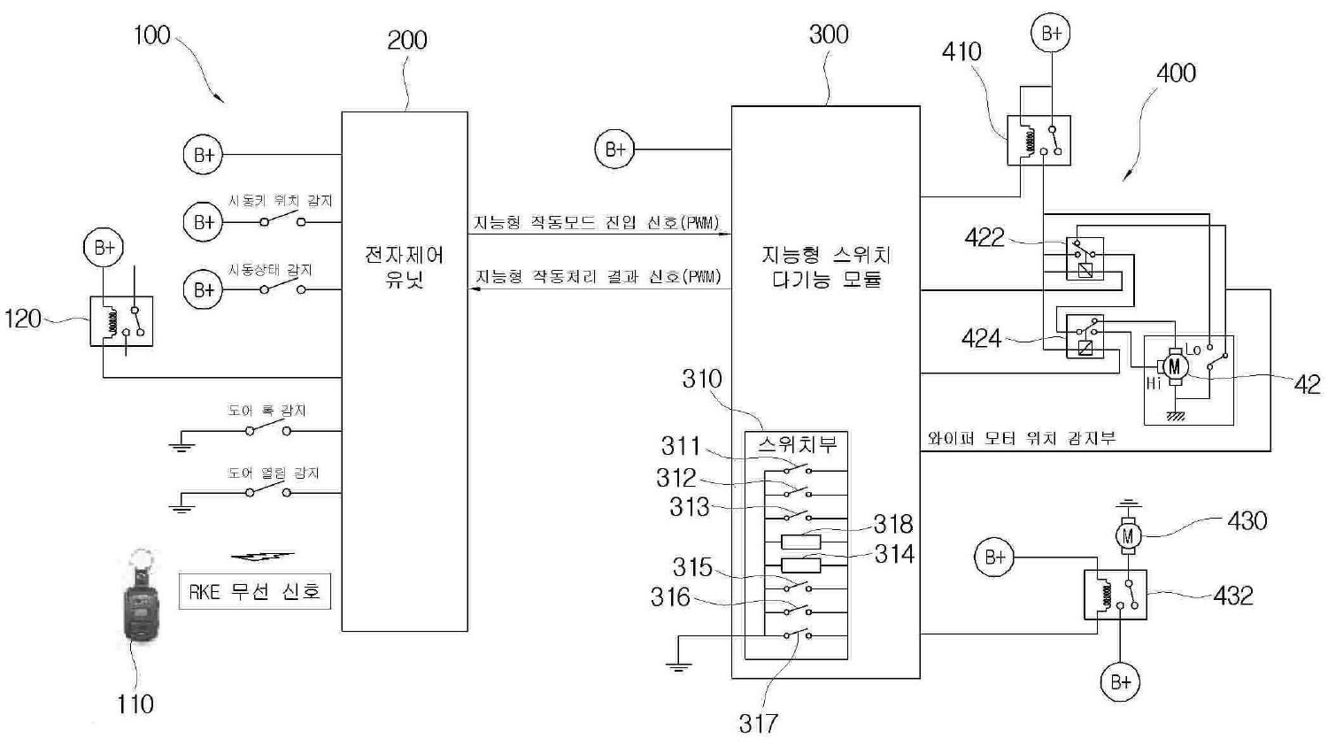
도 2는 본 발명에 따른 와이퍼와 와셔 제어시스템의 블록도이다.2 is a block diagram of a wiper and washer control system according to the present invention.
도시된 바와 같이 입력수단(100), 전자제어유닛(200), 지능형 다기능스위치 모듈(300), 출력수단(400)을 포함하여 구성된다.As shown, it comprises an input means 100,
상기 전자제어유닛(200)에 신호를 입력하는 입력수단(100)으로는 RKE 무선신호를 입력하는 무선키(110)와, 유선으로 비상등 신호를 입력하는 비상등 릴레이(120)로 이루어지고, 또한 상기 전자제어유닛(200)은 시동키 위치 감지신호, 시동 상태 감지신호, 도어 록/언록 감지신호, 도어 개폐 감지신호를 입력받는다.The input means 100 for inputting a signal to the
상기 전자제어유닛(200)은 무선키(110)로 RKE 무선신호가 입력되는 경우나 상기한 여러가지 감지신호가 입력되는 경우에 이를 PWM(펄스폭 변조: Pulse Width Modulation) 신호로 변환하여 지능형 다기능스위치 모듈(300)에 입력하고, 상기 지능형 다기능스위치 모듈(300)은 PWM 신호로 와이퍼와 와셔를 제어한 후 그 처리 결과를 전자제어유닛(200)에 PWM 신호로 송신한다.The
특히, 상기 전자제어유닛(200)은 무선키(100)로 RKE 무선신호가 입력되는 경우에 와이퍼와 와셔를 온도나 차량 조건에 따라 다르게 제어하는 지능형 작동모드 진입 신호인지 아닌지를 판별하여 PWM 신호로 변환한 후, 이를 지능형 다기능스위치 모듈(300)에 입력한다.In particular, when the RKE radio signal is input to the
상기 전자제어유닛은 BCM과 같은 차량에 기존에 구비되어 있는 유닛을 활용하여 와이어를 감소키는 효과가 발생한다.The electronic control unit has an effect of reducing the wire by utilizing a unit that is provided in the vehicle, such as BCM.
상기 지능형 다기능스위치 모듈(300)은 전원 릴레이(410)를 통해 배터리에 연결되어 IG2 OFF 시에도 상기 지능형 다기능스위치 모듈(300)에서 출력수단(400)에 대한 제어가 가능하다.The intelligent
상기 지능형 다기능스위치 모듈(300) 고속모드 스위치(311), 저속모드 스위치(312), 간헐모드 스위치(313), 와이퍼 동작 간격을 조절하는 간헐볼륨 스위치(314), 미스트모드 스위치(315), 와셔 스위치(316), 오프 스위치(317), 온도센서(318)로 구성되는 스위치부(310)를 구비한다.The intelligent
상기 온도센서(318)는 원격의 시동키(110)에 의해 지능형 작동모드로 작동하는 경우에 온도에 따라 와셔와 와이퍼를 제어할 수 있도록 온도를 측정한다.The
특히, 도 3에 나타낸 바와 같이, 온도센서(318)에 의한 입력값(온도)은 히스테리시스를 적용하여 제1 소정온도(예를 들어 1℃) 이하시와 제2 소정온도(예를 들어 4℃) 이상시로 구분하여 제어한다.In particular, as shown in FIG. 3, the input value (temperature) by the
또한, 상기 와이퍼 모터(420) 위치 감지 신호가 와이퍼 작동 중 IG2 OFF시 자동 정위치 제어가 가능토록 상기 지능형 다기능스위치 모듈(300)에 입력으로 연결되어 와이퍼 모터의 정위치 정지 여부를 감지함으로써 지능형 작동모드로 작동하는 경우에 차량 조건 중 와이퍼 모터(420)의 정위치 정지 여부에 따라 와셔와 와이퍼를 제어할 수 있도록 한다.In addition, the wiper motor 420 position detection signal is connected to the intelligent
출력수단(400)은 상기 지능형 다기능스위치 모듈(300)의 제어에 의해 작동하는 부하로, 와이퍼 모터(420), 와셔 모터(430) 등을 포함하여 구성되며, 릴레이에 연결되어 릴레이의 구동에 의해 작동한다.Output means 400 is a load operated by the control of the intelligent
즉, 상기 와이퍼 모터(420)는 지능형 다기능스위치 모듈(300)의 제어에 의해 구동되는 고속 릴레이(424), 저속 릴레이(422)에 각각 연결되며, 상기 와셔 모터(430)는 지능형 다기능스위치 모듈(300)의 제어에 의해 구동되는 와셔 릴레 이(432)에 연결된다.That is, the wiper motor 420 is connected to the
상기한 시스템의 구성에서 지능형 다기능스위 모듈(300)의 스위치부(310)를 구성하는 내부 스위치가 조작되어 ON 신호가 입력되는 경우에 상기 지능형 다기능스위치 모듈(300)은 해당 내부 스위치의 ON 신호 입력에 따라 출력 측의 릴레이(422,432,434)를 구동하여 출력부하인 모터(420,430)를 작동하게 된다.In the configuration of the system, when the internal switch constituting the
이때 온도센서(318)의 온도와 와이퍼 모터(420)의 정위치 정지 여부는 와이퍼나 와셔의 작동 제어에 영향을 미치지 않는다.At this time, the temperature of the
상기 무선키(110)에 구비된 버튼을 눌러 지능형 작동모드 조건 신호가 무선으로 입력되는 경우에 전자제어유닛(200)은 지능형 작동모드 진입 신호를 PWM 신호로 변환하여 지능형 다기능스위치 모듈(300)에 입력하고 상기 지능형 다기능스위치모듈(300)은 지능형 작동모드로 진입하여 주위 온도나 차량 조건에 따라 와이퍼 모터(420)나 와셔 모터(430)를 작동한다.When the intelligent operation mode condition signal is wirelessly input by pressing a button provided on the
도 4는 지능형 작동모드에서 환경조건에 따른 램프 및 와셔 모터 제어표이고, 도 5는 도 2에 나타낸 제어시스템의 작동제어 순서도이다.4 is a lamp and washer motor control table according to environmental conditions in an intelligent operation mode, and FIG. 5 is an operation control flowchart of the control system shown in FIG. 2.
도시된 바와 같이, 운전자가 무선키(110)에 구비된 버튼을 눌러 전자제어유닛(200)에 RKE 무선신호가 입력하면 상기 전자제어유닛(200)은 RKE 무선신호를 PWM 신호로 변환하여 지능형 작동모드 진입 신호인지 판별하고, 지능형 다기능스위치 모듈(300)은 전자제어유닛(200)으로부터 지능형 작동모드 진입 신호가 입력하는지 감시한다(S502).As shown, when the driver presses a button provided on the
상기 PWM 신호에는 도어의 록/언록 신호와 개폐 신호가 포함된다.The PWM signal includes a lock / unlock signal and an open / close signal of the door.
운전자는 예를 들어 무선키(110)에 구비된 Lock 버튼을 길게 1회 이상 누르거나 Unlock 버튼을 2초 이내에 3회 이상 연속해서 눌러 지능형 작동모드로 진입하도록 명령할 수 있고, 이와 같은 경우에 전자제어유닛(200)은 지능형 작동모드 진입 신호로 판별하여 PWM 신호에 도어의 록/언록 신호와 개폐 신호를 포함시켜 지능형 다기능스위치 모듈(300)에 입력한다.The driver may, for example, press and hold the Lock button provided on the
상기 지능형 다기능스위치 모듈(300)은 지능형 작동모드로 진입하여 차량 조건(시동키의 록/언록 신호, 도어의 록/언록 및 개폐 신호, 와이퍼 모터의 정위치 정지 여부)와 온도센서(318)에서 감지한 온도에 따라 PWM 신호를 구분한다(S504).The intelligent
상기 지능형 다기능스위치 모듈은 구분된 PWM 신호에 따라 와이퍼 릴레이(422,424)와 와셔 릴레이(432)의 출력을 ON/OFF한다(S512,S514,S516,S518).The intelligent multifunction switch module turns on / off the outputs of the wiper relays 422 and 424 and the washer relays 432 according to the divided PWM signals (S512, S514, S516 and S518).
예를 들어 S512단계에서 언록 신호가 2초내 3회 이상 입력되고 온도가 제1 소정온도(1℃) 이하인 경우에 도어 신호에 무관하게 제1 PWM 조건에 해당하는 것으로 판단해서, 와이퍼 릴레이(422,424)의 출력은 ON하고 와셔 릴레이(432)의 출력은 OFF하여 와이퍼는 3회전 작동하고 와셔액은 분출하지 않는다.For example, when the unlock signal is input three or more times within 2 seconds in step S512 and the temperature is less than or equal to the first predetermined temperature (1 ° C), the wiper relays 422 and 424 are determined to correspond to the first PWM condition regardless of the door signal. The output of the washer is turned on and the output of the
S514단계에서 상기 언록 신호가 2초내 3회 이상 입력되고 온도가 제2 소정온도(4℃) 이상인 경우에 도어 상태에 무관하게 제2 PWM 조건에 해당하는 것으로 판단해서, 와이퍼 릴레이(422,424)와 와셔 릴레이(432)의 출력을 모두 ON하여, 와셔액을 분출하면서 와이퍼를 3회전 작동한다.In step S514, when the unlock signal is input three or more times within 2 seconds and the temperature is higher than or equal to the second predetermined temperature (4 ° C.), it is determined that it corresponds to the second PWM condition regardless of the door state, and the wiper relays 422 and 424 are washers. All the outputs of the
상기 록 신호가 1회 이상 입력되고 도어가 록/닫힘 상태이며 와이퍼 모터(420)가 정위치에 있는 것으로 감지된 경우에 제3 PWM 조건에 해당하는 것으로 판단해서, 와이퍼 릴레이(422,424)의 출력를 OFF하여 와이퍼를 작동하지 않는다.When the lock signal is input one or more times and the door is locked / closed and the wiper motor 420 is detected to be in the correct position, the lock signal is determined to correspond to the third PWM condition and the output of the wiper relays 422 and 424 is turned off. Do not operate the wiper.
상기 록 신호가 1회 이상 입력되고 도어가 록/닫힘 상태이며 와이퍼 모터(420)가 정위치를 이탈한 것으로 감지된 경우에 제4 PWM 조건에 해당하는 것으로 판단해서, 와이퍼 릴레이(422,424)의 출력을 ON하여 와이퍼를 작동함으로서 정위치에 정지하게 한다.When the lock signal is input one or more times and the door is in the locked / closed state and the wiper motor 420 is detected to be out of position, it is determined that the fourth PWM condition corresponds to the output of the wiper relays 422 and 424. ON to operate the wiper to stop in place.
상기 전자제어유닛(200)과 지능형 다기능스위치(300) 모듈 간의 입력/출력 신호는 PWM 방식 외에 CAN, LIN 등의 다양한 통신 방식을 이용할 수 있음은 물론이다.The input / output signals between the
도 1은 종래 와이퍼 제어시스템의 블록도,1 is a block diagram of a conventional wiper control system,
도 2는 본 발명에 따른 와이퍼 제어시스템의 블록도,2 is a block diagram of a wiper control system according to the present invention;
도 3은 도 2에 나타낸 온도센서에 의한 입력값의 히스테리시스 적용을 나타낸 그래프,3 is a graph showing hysteresis application of an input value by the temperature sensor shown in FIG.
도 4는 지능형 작동모드에서 환경조건에 따른 램프 및 와셔 모터 제어표,4 is a lamp and washer motor control table according to environmental conditions in intelligent operation mode,
도 5는 도 2에 나타낸 제어시스템의 작동제어 순서도.5 is an operation control flowchart of the control system shown in FIG.
<도면의 주요부분에 대한 부호의 설명><Description of the symbols for the main parts of the drawings>
110: 무선키 200: 전자제어유닛110: wireless key 200: electronic control unit
300: 지능형 다기능스위치 모듈300: intelligent multifunction switch module
310: 스위치부 318: 온도센서310: switch unit 318: temperature sensor
410: 전원 릴레이 420: 와이퍼 모터410: power relay 420: wiper motor
424,434: 와이퍼 릴레이 430: 와셔 모터424,434: wiper relay 430: washer motor
432: 와셔 릴레이432: washer relay
Claims (11)
Priority Applications (1)
| Application Number | Priority Date | Filing Date | Title |
|---|---|---|---|
| KR1020070122540A KR100957014B1 (en) | 2007-11-29 | 2007-11-29 | Controlling System of Wiper, Washer and Method thereof |
Applications Claiming Priority (1)
| Application Number | Priority Date | Filing Date | Title |
|---|---|---|---|
| KR1020070122540A KR100957014B1 (en) | 2007-11-29 | 2007-11-29 | Controlling System of Wiper, Washer and Method thereof |
Publications (2)
| Publication Number | Publication Date |
|---|---|
| KR20090055747A KR20090055747A (en) | 2009-06-03 |
| KR100957014B1 true KR100957014B1 (en) | 2010-05-13 |
Family
ID=40987245
Family Applications (1)
| Application Number | Title | Priority Date | Filing Date |
|---|---|---|---|
| KR1020070122540A KR100957014B1 (en) | 2007-11-29 | 2007-11-29 | Controlling System of Wiper, Washer and Method thereof |
Country Status (1)
| Country | Link |
|---|---|
| KR (1) | KR100957014B1 (en) |
Families Citing this family (2)
| Publication number | Priority date | Publication date | Assignee | Title |
|---|---|---|---|---|
| CN107612295B (en) * | 2017-10-16 | 2019-04-19 | 淮北市平祥感应炉有限公司 | A kind of button power controller |
| CN108045345B (en) * | 2017-12-01 | 2020-11-13 | 中车株洲电力机车有限公司 | Rail vehicle washing system and control method |
Citations (2)
| Publication number | Priority date | Publication date | Assignee | Title |
|---|---|---|---|---|
| JP2001158330A (en) * | 1999-11-30 | 2001-06-12 | Yazaki Corp | Wiper deicer |
| KR100764496B1 (en) * | 2006-09-28 | 2007-10-09 | 현대자동차주식회사 | Intelligent wiper system and control method thereof |
-
2007
- 2007-11-29 KR KR1020070122540A patent/KR100957014B1/en not_active IP Right Cessation
Patent Citations (2)
| Publication number | Priority date | Publication date | Assignee | Title |
|---|---|---|---|---|
| JP2001158330A (en) * | 1999-11-30 | 2001-06-12 | Yazaki Corp | Wiper deicer |
| KR100764496B1 (en) * | 2006-09-28 | 2007-10-09 | 현대자동차주식회사 | Intelligent wiper system and control method thereof |
Also Published As
| Publication number | Publication date |
|---|---|
| KR20090055747A (en) | 2009-06-03 |
Similar Documents
| Publication | Publication Date | Title |
|---|---|---|
| US8843270B2 (en) | Wiper motor control system for vehicle | |
| CA2502885A1 (en) | System for remotely starting the engine of a vehicle that has a manual transmission | |
| KR20090103526A (en) | Device and method for wiper position control | |
| KR100801426B1 (en) | Control system of intelligent wiper for cars | |
| CN110040061A (en) | Vehicle light control method and system | |
| KR100957014B1 (en) | Controlling System of Wiper, Washer and Method thereof | |
| CN108974013B (en) | Man-machine permission switching method based on grip strength of steering wheel | |
| JP4985076B2 (en) | Rainfall detection device and information providing system including rainfall detection device | |
| JPH1170857A (en) | Wiper control method | |
| US20150151714A1 (en) | Vehicle control system with suppression of wiper noise | |
| KR100756705B1 (en) | An wiper positioning method for a vehicle | |
| KR100804500B1 (en) | Wiper control device | |
| KR100896904B1 (en) | The supplementation of button starting system in the cranking state | |
| KR20130053354A (en) | Auto-windows | |
| CN105416185A (en) | Pedal system for wirelessly transmitting and receiving automobile electric pedal door opening and closing signals | |
| JP2815367B2 (en) | Automotive door window opening and closing control device | |
| KR100517864B1 (en) | Remote controle system with vehicle diagnostic function | |
| WO2017138519A1 (en) | Automatic wiper device and automatic wiper system | |
| CN211956171U (en) | Automobile body domain controller development device | |
| KR20090090607A (en) | Apparatus and method for controlling wiper and washer | |
| WO2005080151A1 (en) | A control and safety device for vehicles | |
| JP2005001452A (en) | Vehicular power control device | |
| KR100877968B1 (en) | Intelligent multi-function system of car | |
| KR100962234B1 (en) | Multi-Function Switch for Car | |
| KR200291071Y1 (en) | Device of auto closing of the sun roof for car |
Legal Events
| Date | Code | Title | Description |
|---|---|---|---|
| A201 | Request for examination | ||
| E902 | Notification of reason for refusal | ||
| E701 | Decision to grant or registration of patent right | ||
| GRNT | Written decision to grant | ||
| FPAY | Annual fee payment |
Payment date: 20130430 Year of fee payment: 4 |
|
| FPAY | Annual fee payment |
Payment date: 20140430 Year of fee payment: 5 |
|
| FPAY | Annual fee payment |
Payment date: 20150430 Year of fee payment: 6 |
|
| FPAY | Annual fee payment |
Payment date: 20170919 Year of fee payment: 8 |
|
| LAPS | Lapse due to unpaid annual fee |