KR100835759B1 - Image projector, inclination angle detection method, and projection image correction method - Google Patents
Image projector, inclination angle detection method, and projection image correction method Download PDFInfo
- Publication number
- KR100835759B1 KR100835759B1 KR1020067000923A KR20067000923A KR100835759B1 KR 100835759 B1 KR100835759 B1 KR 100835759B1 KR 1020067000923 A KR1020067000923 A KR 1020067000923A KR 20067000923 A KR20067000923 A KR 20067000923A KR 100835759 B1 KR100835759 B1 KR 100835759B1
- Authority
- KR
- South Korea
- Prior art keywords
- screen
- angle
- measuring
- inclination angle
- optical axis
- Prior art date
Links
Images
Classifications
-
- G—PHYSICS
- G03—PHOTOGRAPHY; CINEMATOGRAPHY; ANALOGOUS TECHNIQUES USING WAVES OTHER THAN OPTICAL WAVES; ELECTROGRAPHY; HOLOGRAPHY
- G03B—APPARATUS OR ARRANGEMENTS FOR TAKING PHOTOGRAPHS OR FOR PROJECTING OR VIEWING THEM; APPARATUS OR ARRANGEMENTS EMPLOYING ANALOGOUS TECHNIQUES USING WAVES OTHER THAN OPTICAL WAVES; ACCESSORIES THEREFOR
- G03B21/00—Projectors or projection-type viewers; Accessories therefor
-
- H—ELECTRICITY
- H04—ELECTRIC COMMUNICATION TECHNIQUE
- H04N—PICTORIAL COMMUNICATION, e.g. TELEVISION
- H04N9/00—Details of colour television systems
- H04N9/12—Picture reproducers
- H04N9/31—Projection devices for colour picture display, e.g. using electronic spatial light modulators [ESLM]
- H04N9/3179—Video signal processing therefor
- H04N9/3185—Geometric adjustment, e.g. keystone or convergence
-
- G—PHYSICS
- G03—PHOTOGRAPHY; CINEMATOGRAPHY; ANALOGOUS TECHNIQUES USING WAVES OTHER THAN OPTICAL WAVES; ELECTROGRAPHY; HOLOGRAPHY
- G03B—APPARATUS OR ARRANGEMENTS FOR TAKING PHOTOGRAPHS OR FOR PROJECTING OR VIEWING THEM; APPARATUS OR ARRANGEMENTS EMPLOYING ANALOGOUS TECHNIQUES USING WAVES OTHER THAN OPTICAL WAVES; ACCESSORIES THEREFOR
- G03B21/00—Projectors or projection-type viewers; Accessories therefor
- G03B21/14—Details
-
- G—PHYSICS
- G03—PHOTOGRAPHY; CINEMATOGRAPHY; ANALOGOUS TECHNIQUES USING WAVES OTHER THAN OPTICAL WAVES; ELECTROGRAPHY; HOLOGRAPHY
- G03B—APPARATUS OR ARRANGEMENTS FOR TAKING PHOTOGRAPHS OR FOR PROJECTING OR VIEWING THEM; APPARATUS OR ARRANGEMENTS EMPLOYING ANALOGOUS TECHNIQUES USING WAVES OTHER THAN OPTICAL WAVES; ACCESSORIES THEREFOR
- G03B21/00—Projectors or projection-type viewers; Accessories therefor
- G03B21/54—Accessories
- G03B21/56—Projection screens
-
- H—ELECTRICITY
- H04—ELECTRIC COMMUNICATION TECHNIQUE
- H04N—PICTORIAL COMMUNICATION, e.g. TELEVISION
- H04N5/00—Details of television systems
- H04N5/74—Projection arrangements for image reproduction, e.g. using eidophor
Abstract
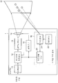
본 발명이 적용되는 프로젝터에서, 거리센서(21)는 프로젝터(1)와 복수의 스크린(31) 위의 점들 사이의 거리들을 측정한다. 각도산출유닛(23)은 거리센서(21)에 의한 측정 결과를 나타내는 복수의 거리 데이터에 기초하여 스크린 표면을 나타내는 공식을 얻고, 투사광의 광축에 대한 스크린(31)의 경사각들(θH 및 θV )을 얻는다. 각도산출유닛(23)은 얻어진 경사각들(θH 및 θV )을 사다리형 정정유닛(12)으로 공급한다. 사다리형 정정유닛(12)은 공급된 경사각들(θH 및 θV )을 이용하여 사다리형 정정을 수행한다.

프로젝터, 스크린, 투사 이미지, 정정, 경사각, 거리센서
In the projector to which the present invention is applied, the distance sensor 21 measures the distances between the projector 1 and the points on the plurality of screens 31. The angle calculation unit 23 obtains a formula representing the screen surface based on the plurality of distance data representing the measurement result by the distance sensor 21, and inclination angles θ H and θ of the screen 31 with respect to the optical axis of the projection light. V ) The angle calculation unit 23 supplies the obtained inclination angles θ H and θ V to the ladder correction unit 12. The ladder correction unit 12 performs ladder correction using the supplied inclination angles θ H and θ V.
Projector, screen, projected image, correction, tilt angle, distance sensor
Description
본 발명은 프로젝터 장치, 프로젝터의 경사각 획득방법, 및 투사 이미지 정정방법에 관한 것이다.The present invention relates to a projector device, a tilt angle acquisition method of a projector, and a projection image correction method.
프로젝터는 스크린 위에 이미지를 표시하기 위한 장치이다. 프로젝터는 스크린을 향하여 빛을 투사하고 스크린 위에 이미지를 표시한다.Projectors are devices for displaying images on the screen. The projector projects light towards the screen and displays the image on the screen.
프로젝터가 지표면에 대해 경사되지 않고 스크린이 지표면에 수직으로 위치되면, 이미지는 스크린 위에 왜곡되지 않고 표시된다.If the projector is not tilted with respect to the ground and the screen is positioned perpendicular to the ground, the image is displayed without distortion on the screen.
그러나, 지표면에 대해 프로젝터가 경사되면, 스크린 위의 이미지가 왜곡된다. 이를 방지하기 위하여 소정의 종래 프로젝터들은 내부에 가속센서를 구비한다. 가속센서는 지표면에 대한 프로젝터의 경사각을 검출한다. 프로젝터는 검출된 경사각에 기초하여 사다리형(trapezoidal) 정정을 수행한다. 그러한 프로젝터는 예컨대, 미심사의 일본 특허출원 공개 제 2001-339671호 3면 및 도 1에 개시된다.However, if the projector is tilted with respect to the ground surface, the image on the screen is distorted. To prevent this, some conventional projectors have an acceleration sensor therein. The acceleration sensor detects the tilt angle of the projector with respect to the ground surface. The projector performs trapezoidal correction based on the detected tilt angle. Such a projector is disclosed, for example, in Japanese Unexamined Patent Application Publication No. 2001-339671 on
그러나, 실제로, 이 스크린은 지표면에 수직일 필요는 없다.In practice, however, the screen need not be perpendicular to the earth's surface.
그러므로, 사다리형 정정의 정정량을 결정하기 위하여 지표면에 대한 프로젝 터의 경사각 및 스크린에 수직인 축에 대한 프로젝터의 경사각이 필요하다. 이들 경사각들이 측정될 수 있으면, 사다리형 정정이 수행될 수 있다. Therefore, in order to determine the correction amount of the ladder correction, the inclination angle of the projector with respect to the ground surface and the inclination angle of the projector with respect to the axis perpendicular to the screen are required. If these inclination angles can be measured, ladder correction can be performed.
종래의 프로젝터들은 이와 같이 외형을 정정하기 위하여 이미지의 왜곡된 외형을 정정한다.Conventional projectors thus correct the distorted appearance of the image to correct the appearance.
그러나, 종래의 프로젝터들은 다음의 문제들을 가진다.However, conventional projectors have the following problems.
우선, 상기 설명된 바와 같이, 이미지의 사다리형 정정을 위해 필요한 경사각들은 지표면에 대한 프로젝터의 경사각이며, 스크린에 수직인 축에 대한 프로젝터의 경사각이다. 그러므로, 지표면에 대한 프로젝터의 경사각이 검출되어도 스크린에 대한 프로젝터의 경사각이 정확하게 측정될 수 없거나 측정된 결과가 프로젝터에 제공될 수 없으면, 사다리형 정정은 정확하게 수행될 수 없다. First, as explained above, the inclination angles necessary for the ladder correction of the image are the inclination angles of the projector with respect to the ground surface, and the inclination angle of the projector with respect to the axis perpendicular to the screen. Therefore, even if the inclination angle of the projector with respect to the ground surface is detected, if the inclination angle of the projector with respect to the screen cannot be measured accurately or the measured result cannot be provided to the projector, ladder-type correction cannot be performed correctly.
둘째, 가속센서를 구비한 종래의 프로젝터들은 지표면에 평행한 방향에서의 프로젝터에 대한 스크린의 경사각을 무시한다. 실제로, 수평방향으로 프로젝터에 대한 스크린의 경사각이 존재할 수 있다. 가속센서는 투사된 빛의 광축에 대한 스크린의 경사각을 검출할 수 없다. 그러므로, 종래의 가속센서를 구비한 프로젝터들은 수평방향에서 프로젝터에 대한 스크린의 경사각에 기초하여 사다리형 정정을 수행할 수 없다.Second, conventional projectors with acceleration sensors ignore the tilt angle of the screen relative to the projector in a direction parallel to the ground surface. In practice, there may be an inclination angle of the screen with respect to the projector in the horizontal direction. The acceleration sensor cannot detect the tilt angle of the screen with respect to the optical axis of the projected light. Therefore, the projectors with the conventional acceleration sensor cannot perform the ladder type correction based on the inclination angle of the screen with respect to the projector in the horizontal direction.
상기 기재한 문서의 상세한 설명이 여기 포함된다. The detailed description of the documents set forth above is included herein.
본 발명의 목적은 스크린 위에 표시되는 투사 이미지를 정확하게 정정할 수 있는 프로젝터 장치, 프로젝터의 경사각 획득 방법, 이미지 왜곡의 정정방법을 제공하는 것이다.SUMMARY OF THE INVENTION An object of the present invention is to provide a projector device capable of accurately correcting a projected image displayed on a screen, a method of obtaining a tilt angle of a projector, and a method of correcting image distortion.
본 발명의 바람직한 실시예들중 하나는, 프로젝터 장치로서, 스크린(31) 위의 복수의 측정점들과 그 자체 사이의 거리들을 측정하고 측정 결과들을 나타내는 복수의 거리 데이터를 출력하는 거리센서(21);One of the preferred embodiments of the present invention is a projector device, which measures a distance between a plurality of measuring points on the
거리센서(21)로부터 출력된 복수의 거리 데이터를 이용하여 투사광이 그 위에 투사되는 스크린(31)과 프로젝터 장치(1)로부터 투사된 투사광의 광축 사이의 위치 관계를 나타내는 스크린 공식을 획득하고, 얻어진 스크린 공식을 이용하여 스크린(31) 표면에 대한 광축의 경사각을 획득하는 각도산출유닛(23);Using a plurality of distance data output from the
각도산출유닛(23)에 의하여 얻어진 스크린(31) 표면에 대한 광축의 경사각을 이용하여 스크린(31) 표면에 표시되는 투사 이미지의 왜곡을 정정하는 정정유닛(12); 및A
정정유닛(12)에 의하여 정정된 투사 이미지를 투사광으로 변환하고 투사 이미지를 스크린(31) 표면 위에 투사하는 광변조유닛(13)을 구비하여 이루어지는 프로젝터 장치이다.And a
본 발명의 바람직한 실시예들중 다른 하나는, 프로젝터 장치로서, 서로 교차하는 스크린(31) 위의 복수의 측정선들 각각 위에 위치되는 복수의 측정점들과 그 자체들 각각 사이의 거리들을 측정하고, 측정 결과들을 나타내는 복수의 거리 데이터를 각각 출력하는 복수의 거리센서들(21A, 21B);Another one of the preferred embodiments of the present invention is a projector device, which measures the distance between each of a plurality of measuring points and each of them which is located above each of the plurality of measuring lines on the
복수의 거리센서들(21A, 21B)에서 각각 출력된 복수의 거리 데이터를 이용하여 프로젝터 장치(1)로부터 투사된 투사광의 광축에 수직인 표면에 대한 복수의 측정선들의 경사각들을 획득하고, 얻어진 복수의 경사각들을 이용하여 스크린(31)의 표면에 대한 광축의 경사각을 획득하는 각도산출유닛(23);Using the plurality of distance data output from the plurality of
각도산출유닛(23)에 의하여 얻어진 스크린(31) 표면에 대한 광축의 경사각을 이용하여 스크린(31)의 표면에 표시될 투사 이미지의 왜곡을 정정하는 정정유닛(12); 및 A
정정유닛(12)에 의하여 정정된 투사 이미지를 투사광으로 변환하고 투사 이미지를 스크린(31) 표면 위에 투사하는 광변조유닛(13)을 구비하여 이루어지는 프로젝터 장치이다.And a
본 발명의 바람직한 실시예들의 또 다른 하나는, 스크린(31)의 표면에 대한 프로젝터 장치(1)의 경사각을 획득하기 위한 경사각 획득방법으로서, Another one of the preferred embodiments of the present invention is a method of obtaining an inclination angle for obtaining an inclination angle of the
스크린(31) 위의 복수의 측정점들 및 프로젝터 장치(1) 사이의 거리들을 측정하는 측정 단계;A measuring step of measuring distances between the plurality of measuring points on the
측정 단계의 측정결과를 나타내는 복수의 거리 데이터를 이용하여 투사광이 그 위에 투사되는 스크린(31)의 표면과 프로젝터 장치(1)로부터 투사된 투사광의 광축 사이의 위치 관계를 나타내는 스크린 공식을 얻는 스크린 공식 획득단계; 및A screen which obtains a screen formula indicating the positional relationship between the surface of the
얻어진 스크린 공식을 이용하여 광축에 대한 스크린(31) 표면의 경사각을 획득하는 경사각 획득 단계를 구비하여 이루어지는 경사각 획득방법이다. And an inclination angle obtaining step of obtaining an inclination angle of the surface of the
본 발명의 바람직한 실시예들의 또 다른 하나는, 스크린(31)의 표면에 대한 프로젝터 장치(1)의 경사각을 획득하기 위한 경사각 획득방법으로서:Another one of the preferred embodiments of the present invention is a method of obtaining an inclination angle for obtaining an inclination angle of the
서로 교차하는 스크린(31) 위의 복수의 측정선들 각각 위에 위치된 복수의 측정점들 및 프로젝터 장치(1) 사이의 거리들을 측정하는 측정단계;A measuring step of measuring distances between the plurality of measuring points and the
복수의 측정선들 각각과 프로젝터 장치(1)의 광축에 수직인 가상 스크린 표면 사이에 형성되는 각도를 획득하는 각도획득단계; 및An angle obtaining step of obtaining an angle formed between each of the plurality of measurement lines and a virtual screen surface perpendicular to the optical axis of the
각도획득단계에서 얻어진 각각의 각도를 스크린(31) 표면에 대한 프로젝터 장치(1)의 광축의 경사각으로서 해석하는 해석단계를 구비하여 이루어지는 경사각 획득방법이다.An inclination angle acquisition method comprising an analysis step of analyzing each angle obtained in the angle acquisition step as an inclination angle of the optical axis of the
본 발명의 바람직한 실시예들의 또 다른 하나는, 투사 이미지의 왜곡을 정정하기 위한 투사 이미지 정정방법으로서:Another one of the preferred embodiments of the present invention is a projection image correction method for correcting distortion of a projection image:
정해진 기준점과 스크린(31) 위의 복수의 측정점들 사이의 거리들을 측정하는 측정 단계;A measuring step of measuring distances between a predetermined reference point and a plurality of measuring points on the
측정단계의 측정 결과를 나타내는 복수의 거리 데이터를 사용하여 스크린(31) 위에 투사되는 투사광의 광축과 스크린(31) 사이의 위치 관계를 나타내는 스크린 공식을 얻는 스크린 공식 획득단계; A screen formula acquiring step of obtaining a screen formula indicating a positional relationship between the optical axis of the projection light projected onto the
얻어진 스크린 공식을 사용하여 스크린(31)의 표면에 대한 광축의 경사각을 얻는 경사각 획득단계; 및An inclination angle obtaining step of obtaining an inclination angle of the optical axis with respect to the surface of the
경사각 획득단계에서 얻어진 스크린(31) 표면에 대한 광축의 경사각을 사용하여 스크린(31) 표면 위에 표시될 투사 이미지의 왜곡을 정정하는 정정단계를 구비하여 이루어지는 투사 이미지 정정방법이다.And a correction step of correcting the distortion of the projection image to be displayed on the
본 발명의 바람직한 실시예들의 또 다른 하나는, 투사 이미지의 왜곡을 정정하기 위한 투사 이미지 정정방법으로서: Another one of the preferred embodiments of the present invention is a projection image correction method for correcting distortion of a projection image:
서로 교차하는 스크린(31) 위의 복수의 측정선들 각각 위에 위치된 복수의 측정점들 및 프로젝터 장치(1) 사이의 거리들을 측정하는 측정 단계;A measuring step of measuring distances between the plurality of measuring points and the
복수의 측정선들 각각과 프로젝터 장치(1)의 광축에 수직인 가상 스크린 표면 사이에 형성되는 각도를 획득하는 각도획득단계; An angle obtaining step of obtaining an angle formed between each of the plurality of measurement lines and a virtual screen surface perpendicular to the optical axis of the
각도획득단계에서 얻어진 각각의 각도를 스크린(31) 표면에 대한 프로젝터 장치(1)의 광축의 경사각으로서 해석하는 각도해석단계; 및An angle analysis step of analyzing each angle obtained in the angle obtaining step as an inclination angle of the optical axis of the
각도해석단계에서 해석에 의하여 얻어지는 스크린(31) 표면에 대한 프로젝터(1)의 광축의 경사각들을 사용하여 스크린(31) 표면 위에 표시될 투사 이미지의 왜곡을 정정하는 정정단계를 구비하여 이루어지는 투사 이미지 정정방법이다.Projection image correction comprising a correction step of correcting the distortion of the projection image to be displayed on the
본 발명이 적용되는 프로젝터는 스크린에 촛점이 일치된 투사 이미지의 정정을 정확하게 수행할 수 있다.The projector to which the present invention is applied can accurately perform correction of a projected image whose focus is matched on a screen.
본 발명의 상기 목적들, 다른 목적들 및 이점들은 이하의 상세한 설명 및 첨부 도면들의 이해를 통해 더욱 명확해질 것이며, 여기에서:These and other objects and advantages of the present invention will become more apparent from the following detailed description and understanding of the accompanying drawings, in which:
도 1은 본 발명의 제 1 실시예에 따른 프로젝터의 구조를 도시하는 블럭도이며;1 is a block diagram showing the structure of a projector according to a first embodiment of the present invention;
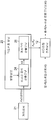
도 2는 도 1에 도시된 각도 산출유닛의 구조를 도시하는 블럭도이며;FIG. 2 is a block diagram showing the structure of the angle calculating unit shown in FIG. 1;
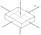
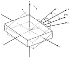
도 3은 프로젝터의 좌표계를 도시하는 도면이며;3 is a diagram illustrating a coordinate system of a projector;
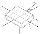
도 4는 도 3의 좌표계의 x축 둘레로 프로젝터가 회전하는 상태를 도시하는 도면이며;4 is a view showing a state in which the projector rotates around the x-axis of the coordinate system of FIG. 3;
도 5는 도 3의 좌표계의 x축 둘레로 프로젝터가 회전한 후에 y축 둘레로 회전하는 상태를 도시하는 도면이며;FIG. 5 is a diagram illustrating a state in which the projector rotates around the y axis after the projector rotates around the x axis of the coordinate system of FIG. 3;
도 6은 광축에 대한 스크린의 경사각을 획득하기 위한 방법을 설명하기 위한 도면이며;6 is a diagram for explaining a method for obtaining an inclination angle of a screen with respect to an optical axis;
도 7은 스크린 위의 이미지와 도 6에 도시된 경사각 사이의 위치 관계를 설명하기 위한 도면이며;FIG. 7 is a diagram for explaining the positional relationship between the image on the screen and the inclination angle shown in FIG. 6;
도 8은 스크린 위에 설정된 좌표계를 도시하는 도면이며;8 is a diagram showing a coordinate system set on a screen;
도 9는 도 8에 도시된 좌표계의 y축 둘레로 스크린이 회전하는 상태를 도시하는 도면이며;FIG. 9 is a view showing a state in which the screen is rotated around the y axis of the coordinate system shown in FIG. 8; FIG.
도 10은 도 8에 도시된 좌표계의 y축 둘레로 스크린이 회전한 후에 x축 둘레로 회전하는 상태를 도시하는 도면이며;FIG. 10 is a diagram showing a state in which the screen rotates around the y axis after the screen is rotated around the y axis of the coordinate system shown in FIG. 8;
도 11은 거리 데이터에 기초하여 측정된 지점의 좌표를 획득하는 방법을 설명하는 도면이며;11 is a diagram for explaining a method of obtaining coordinates of a measured point based on distance data;
도 12A 내지 12C는 도 1에 도시된 사다리형 정정유닛과 광변조 유닛의 작동을 도시하는 도면들이며;12A to 12C are views showing the operation of the ladder correction unit and the light modulation unit shown in FIG. 1;
도 13은 본 발명의 제 2 실시예에 따른 프로젝터에 포함된 거리센서들의 배치를 도시하는 도면으로서, 특히 프로젝터의 전면(좌측 도면), 프로젝터의 측면(우측 도면)을 도시하며;Fig. 13 is a diagram showing the arrangement of distance sensors included in the projector according to the second embodiment of the present invention, in particular showing the front side (left side view) of the projector and the side side (right side view) of the projector;
도 14는 제 2 실시예에 따른 프로젝터를 구성하는 각도 산출유닛의 구조를 도시하는 블럭도이며;14 is a block diagram showing the structure of an angle calculating unit constituting the projector according to the second embodiment;
도 15는 하나의 거리센서에 의해 측정된 거리를 표시하는 2개의 거리 데이터에 기초하여 각도를 산출하기 위한 도 14에 도시된 각도 산출유닛에 의하여 수행되는 산출 방법을 설명하는 도면이다.FIG. 15 is a view for explaining a calculation method performed by the angle calculating unit shown in FIG. 14 for calculating an angle based on two distance data indicating a distance measured by one distance sensor.
본 발명의 실시예들에 따른 프로젝터들이 도면을 참조하여 설명될 것이다.Projectors in accordance with embodiments of the present invention will be described with reference to the drawings.
(제 1 실시예)(First embodiment)
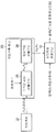
제 1 실시예에 따른 프로젝터(1)는 스케일러(scaler)(11), 사다리형 정정유닛(12), 광변조 유닛(13), 투사렌즈(14), 광학기구(15), 및 스크린 각도센서(16)를 구비한다. The
스케일러(11)는 이미지 신호의 해상도를 조정한다.The scaler 11 adjusts the resolution of the image signal.
사다리형 정정유닛(12)은 스케일러(11)에 의하여 정정된 해상도를 가지는 이미지 신호에 대해 사다리형 정정을 수행한다. The
사다리형 정정유닛(12)은 스크린 각도센서(16)로부터 공급된 스크린(31) 표면의 경사각들(θV 및 θH)에 기초하여 스크린(31) 위에 투사된 정정 전의 투사 이미지 내의 정정 후의 투사 이미지의 위치와 형상을 설정한다. 이어서, 사다리형 정정유닛(12)은 일시적으로 연속해서 이미지 신호를 돌출 변형시켜 사다리형 변형을 수행한다. 경사각(θV)은 투사광의 광축에 대해 수직 방향으로 스크린(31)의 경사를 표시한다. 경사각(θH)은 광축에 대해 수평 방향으로 스크린(31)의 경사각을 표시한다. The
사다리형 정정유닛(12)은 투사 이미지를 정정하기 위한 정정량으로 경사각들(θV 및 θH)을 해석하기 위한 해석표에 따라 투사 이미지를 정정하기 위한 정정량을 획득한다. 이어서, 사다리형 정정유닛(12)은 정정된 후에 이미지 신호를 출력한다. 해석표를 사용하는 경우, 사다리형 정정유닛(12)은 사전 생성된 해석표를 저장하기 위한 메모리를 가진다. 대신에, 사다리형 정정유닛(12)은 경사각들(θV 및 θH)이 공급될 때마다, 스크린 평면을 나타내는 공식을 사용하여 사다리형 정정을 수행하도록 구성될 수 있다. 해석표를 생성하기 위하여, (1)정정 전의 사각형 형상이 경사각들(θV 및 θH)과 확대 배율에 기초하여 얻어지며; (2) 정정 후에 획득된 사각형은 정정되기 전의 사각형 내에 규정되며, 정정 후에 얻어진 사각형의 좌표가 얻어지며; (3) 정정 전의 사각형의 좌표는 좌표들의 역변환에 의하여 정정 후에 얻어진 사각형의 좌표들에 기초하여 얻어지며, 이로써 변환 방식이 결정되며; (4) 역변환에 의하여 얻어진 좌표들로부터 회로 파라미터가 유도된다(이 파라미터는 사전에 유도되며 해석표로서 메모리에 저장된다). 해석표가 사용되지 않으면, 필요한 바와 같은 (1) 내지 (4)의 과정들을 수행함으로써 동일한 정정 동작이 실현된다.The
광변조 유닛(13)은 사다리형 정정유닛(12)으로부터 출력된 정정 후의 이미지 신호를 투사광으로 변환한다. 예컨대, 투과형 또는 반사형 액정 패널 또는 디지털 마이크로미러 장치(DMD)가 광변조 유닛(13)으로 사용된다.The
투사 렌즈(14)는 정정 후 이미지 신호로부터 광변조 유닛(13)에 의하여 광으로 변환된 이미지를 스크린(31) 위에 표시한다. The
광학기구(15)는 스크린 각도센서(16)에 의하여 검출된 경사각들(θV 및 θH)에 기초하여 투사 렌즈(14)의 초점 등을 조정한다. 프로젝터(1)가 확대 기구를 구비한 경우, 광학 기구(15)는 또한 확대 제어를 수행하며, 사다리형 정정유닛(12)에 확대 배율에 대한 정보를 제공한다. 프로젝터(1)의 확대 배율은 투사거리 및 투사 이미지의 크기의 비율을 상수로 곱하여 얻어진 값이다(확대 배율은 투사 이미지의 폭/투사 거리 = 2 × tan(시야각의 반)에 비례).The
확대 배율이 변화될 수 있는 확대 가변 범위는 넓으며, 확대 배율에 기초한 사다리형 정정용 정정량의 변화는 무시할 수 없게 크다. 그러므로 사다리형 정정유닛(12)은 광학기구(15)로부터 공급된 확대 배율을 사용하여 사다리형 정정을 수행한다.The magnification variable range in which the magnification can be changed is wide, and the change of the ladder-type correction correction amount based on the magnification is not negligible. Therefore, the
그러나, 프로젝터(1)가 확대 기구를 구비하지 않는 경우 또는 프로젝터(1)가 확대 기구를 구비하나 확대 가변 범위가 좁은 경우, 사다리형 정정유닛(12)은 확대 배율을 상수로 간주하여 사다리형 정정을 수행한다. However, when the
스크린 각도센서(16)는 프로젝터(1)에 의하여 투사된 광의 광축에 대한 스크린(31)의 표면의 경사각(θV 및 θH)을 검출한다. 스크린 각도센서(16)는 거리센서(21), 제어유닛(22), 및 각도 산출유닛(23)을 구비한다.The
거리센서(21)는 프로젝터(1)와 스크린(31) 위의 복수의 측정 지점들 사이의 거리들을 측정한다. 거리센서(21)는 측정 결과들을 표시하는 거리 데이터를 출력한다. 거리센서(21)가 프로젝터(1)와 스크린(31) 위의 적어도 3개의 측정 지점들 사 이의 거리들을 측정할 수 있으면 족하다. 거리센서(21)는 능동형 또는 수동형일 수 있다.The
제어유닛(22)은 프로젝터(1)와 복수의 스크린(31) 위의 지점들 사이의 거리를 측정하도록 제어한다. 거리를 측정하기 위하여 제어유닛(22)은 스크린(31) 위에 적외선 광 스팟(능동형의 경우) 또는 정해진 이미지 패턴(수동형)을 투사한다. The
각도 산출유닛(23)은 거리센서(21)에 의하여 측정된 프로젝터(1)와 스크린(31) 상의 복수의 측정 지점들 사이의 거리를 표시하는 거리 데이터에 기초하여 스크린(31) 상에 경사각(θV 및 θH)을 산출한다. 각도 산출유닛(23)은 예컨대, 디지탈 신호 프로세서(DSP) 또는 컴퓨터로 구성된다. 도 2에 도시된 바와 같이, 각도 산출유닛(23)은 스크린 공식 산출유닛(24), 경사각 산출유닛(25)을 포함한다.The
스크린 공식 산출유닛(24)은 복수의 측정 지점들에 대한 거리 데이터에 기초하여 스크린(31)의 스크린 평면을 표시하는 공식을 유도한다. 경사각 산출유닛(25)은 스크린 공식 산출유닛(24)을 통해 유도된 스크린 평면을 나타내는 공식을 사용하여 스크린(31)의 경사각들(θV 및 θH)을 산출한다. The screen
여기에서, 좌표계의 원점이 프로젝터(1)의 중심에 설정된 경우 및 좌표계의 원점이 스크린(31)의 표면에 설정된 경우 각각에서 경사각들(θV 및 θH)에 대해 설명한다. 좌표계는 x, y, z축으로 이루어진 3차원 직교 좌표계이다.Here, the inclination angles θ V and θ H will be described in each case when the origin of the coordinate system is set at the center of the
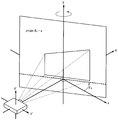
우선, 좌표계의 원점이 도 3에 도시된 바와 같이 프로젝터(1)의 중심에 설정된 경우를 설명한다. 스크린(31)이 z축에 수직이고 x축, y축에 평행이면, 스크린은 z=d인 위치에 존재한다. 도 3 내지 도 7은 투사렌즈(14)의 입사 동공의 위치가 좌표계의 원점에 일치하도록 도시된다.First, the case where the origin of the coordinate system is set at the center of the
스크린(31)이 경사되지 않고 프로젝터(1)가 경사된 경우를 고려한다. 이러한 경우, 스크린(31)은 z=d인 위치에 존재하는 것으로 상정한다.Consider the case where the
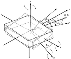
이 때, 주의를 기울여야 하는 것은 프로젝터(1)의 경사 순서이다. 프로젝터(1)가 경사되는 경우, 우선 프로젝터(1)는 도 4에 도시된 바와 같이, 회전축으로서 x축 둘레에 경사각(θV1) 만큼 경사진다. 이어서, 프로젝터(1)는 도 5에 도시된 바와 같이, 회전축으로서 y축 둘레에 경사각(θH1) 만큼 경사된다. 도 5의 z'축은 z축을 회전축으로서의 y축 둘레로 경사각(θH1) 만큼 경사시켜 도달되는 것이다. 프로젝터(1)로부터의 투사광의 광축은 z > 0 인 범위에서 z'축 위에 존재한다.At this time, attention should be paid to the tilting order of the
도 4 및 도 5에 도시된 경사각(θV1)은 프로젝터(1)가 x축 둘레로 회전되는 경우, 프로젝터(1)로부터 투사된 광의 광축과 z축 사이에 형성된 각도이다. 도 5에 도시된 경사각(θH1)은 프로젝터(1)가 더욱 y축 둘레로 회전된 경우 프로젝터(1)로부터 투사된 광의 광축의 z-x 평면에 사상된 z축과 z'축 사이에 형성된 각도이다.The inclination angle θ V1 shown in FIGS. 4 and 5 is an angle formed between the optical axis and the z axis of the light projected from the
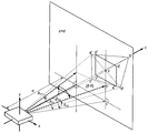
회전 순서가 역전되면, 즉 도 6 및 도 7에 도시된 바와 같이, 프로젝터(1)가 회전축으로서 y축 둘레에 경사각(θH2) 만큼 경사지고 이어서 회전축으로서 x' 축 둘레에 경사각(θV2) 만큼 경사지면, 경사각들(θH1및θH2)의 값과 경사각(θV1및θV2)의 값은 각각 같다.When the rotation order is reversed, i.e. as shown in Figs. 6 and 7, the
그러나, 프로젝터(1)가 회전축으로서 y축 둘레에 우선 회전되면, 프로젝터(1)가 다음에 그 둘레로 회전되는 회전축은 경사각(θH2) 만큼 회전축으로서 y축 둘레에 x축을 경사시켜 도달되는 x'축이다.However, when the
도 6 및 도 7에 있어서, 회전 순서가 역전되어도 회전축이 잘못되지 않으면 동일한 상태가 나타나는 것으로 알려져 있다. 6 and 7, even when the rotation order is reversed, it is known that the same state appears when the rotation axis is not wrong.
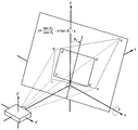
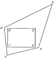
도 7에서, "d"는 프로젝터(1)의 중심과 스크린(31) 사이의 거리를 나타낸다. 스크린(31) 위의 두 사각형은 프로젝터(1)가 회전 후의 투사 이미지들이다. 사각형(a'b'c'd')은 사다리형 정정유닛(12)이 사다리형 정정을 수행하지 않은 경우의 투사 이미지를 나타낸다. 사각형(p'q'r's')은 사다리형 정정유닛(12)이 사다리형 정정을 수행한 후의 투사 이미지를 나타낸다.In FIG. 7, "d" represents the distance between the center of the
도 7에 도시된 바와 같이, 사다리형 정정유닛(12)이 사다리형 정정을 수행하는 것에 의하여 사각형(a'b'c'd')은 사각형(p'q'r's')으로 변환된다.As shown in FIG. 7, the rectangle a'b'c'd 'is converted into a rectangle p'q'r's' by the
점("t")은 프로젝터(1)가 우선 경사각(θH2) 만큼 y축 둘레로 회전된 경우 프로젝터(1)의 광축과 스크린(31)의 임시 교차점을 나타낸다. 점("u")은 프로젝터(1)가 먼저 x축 둘레로 경사각(θV1) 만큼 회전한 후에 경사각(θH1) 만큼 y축 둘레로 회전한 경우의 프로젝터(1)의 광축과 스크린(31)의 실제 교차점을 나타낸다. 점("v")은 사각형(a'b'c'd')의 두 대각선들의 교차점을 나타낸다.The point "t" represents the temporary intersection of the optical axis of the
도 7에 도시된 바와 같이, 점("u")이 임시 교차점인 점("t")의 바로 위에 위치되면, 점("v")은 점("u") 바로 위에 위치된다. 그러므로, 경사각들이 (θV2 및 θ H2)에 의하여 표시되면 설명은 더욱 이해하기 용이하게 될 것이다. As shown in FIG. 7, when the point "u" is located directly above the point "t" which is a temporary intersection, the point "v" is located directly above the point "u". Therefore, the description will be easier to understand if the inclination angles are represented by (θ V2 and θ H2 ).
다음에, 프로젝터(1)가 아니고 스크린(31)이 경사되는 경우를 설명한다. Next, the case where the
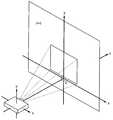
도 8은 스크린(31)이 경사되기 전의 상태를 도시한다. 이해를 용이하게 하기 위하여, 좌표계는 도 8에 도시된 바와 같이 설정된다. 특히, 좌표계의 원점이 스크린(31) 위의 점(O)으로 설정된다. 이해가 쉽도록 점(O)은 프로젝터(1)로부터 투사된 광의 광축과 스크린(31)의 교차점으로 상정된다.8 shows the state before the
이러한 경우, 스크린 평면을 나타내는 공식은 Z = 0 이다.In this case, the formula representing the screen plane is Z = 0.
스크린(31)이 도 9에 도시된 바와 같이, 경사각(θH) 만큼 y축 둘레로 회전되면, 스크린(31)의 평면은 다음 식(15)에 의하여 표시된다.As the
![]()
![]()
스크린(31)이 더욱 도 10에 도시된 바와 같이 경사각(θV) 만큼 x축 둘레로 회전되면, 식(15)은 다음 식(16)으로 변경된다.When the

문제되는 것은 회전 순서이다. 도 3 내지 도 5에 도시된 바와 같은 프로젝터(1)의 회전 순서에 역의 회전 순서로 하는 것이 필요하다. 즉, 도 9 및 도 10에 도 시된 바와 같이, 스크린(31)은 우선 경사각(θH) 만큼 y축 둘레로 회전되고 이어서 경사각(θV) 만큼 x축 둘레로 회전된다. The problem is the rotation order. It is necessary to reverse the rotation order of the
이로써, 식(16)의 경사각들(θH 및 θV)은 도 6 및 도 7에 도시된 경사각들(θH1 및 θV1)과 일치한다. 즉, 좌표계의 원점이 프로젝터(1)의 중심에 설정되고 프로젝터(1)가 경사된 경우와 좌표계의 원점이 스크린(31)의 표면에 설정되고 스크린(31)이 경사된 양자의 경우에서, 프로젝터(1)의 경사각(θH1 및 θV1) 및 스크린(31)의 경사각(θH 및 θV)은 각각 서로 일치한다.Thus, the inclination angles θ H and θ V of equation (16) coincide with the inclination angles θ H1 and θ V1 shown in FIGS. 6 and 7. That is, in the case where the origin of the coordinate system is set at the center of the
다음, 프로젝터(1)와 스크린(31) 위의 측정 지점 사이의 거리를 나타내는 거리 데이터에 기초한 경사각들(θH 및 θV)의 산출 방법이 설명된다. Next, a method of calculating the inclination angles θ H and θ V based on the distance data representing the distance between the
스크린(31)의 평면은 다음 식(17)에 의하여 표시된다. 여기 사용되는 좌표계는 원점이 프로젝터(1)의 중심이고 x, y, z축으로 구성되는 3차원 직교 좌표계이다.The plane of the
![]()
![]()
(a, b, c는 상수)(a, b, c are constants)
사전 설정된 방향에 대한 방향 정보가 존재하면, 복수의 거리 데이터, 스크린(31) 위의 측정 지점에 대한 3차원 좌표들(x, y, z)이 얻어질 수 있다. 3세트의 방향 정보와 거리 데이터들이 존재하면, 3세트의 3차원 좌표들{(x1, y1, z1), (x2, y2, z2), (x3, y3, z3)}이 얻어질 수 있다.If there is direction information for the preset direction, a plurality of distance data, three-dimensional coordinates (x, y, z) for the measuring point on the
이러한 경우, 식(17)에 기초하여 3차 연립 방정식들이 구축된다. 식(17)의 계수들(a b, c)은 이들 연립 방정식들을 풀어 얻어질 수 있다. 계수("c")가 z축의 평행 운동을 나타내므로 "c"를 찾을 필요는 없다. In this case, cubic system equations are constructed based on equation (17). The coefficients a b and c of equation (17) can be obtained by solving these simultaneous equations. It is not necessary to find "c" because the coefficient "c" represents the parallel movement of the z axis.
식(16)과 식(17)을 비교함으로써 계수들("a", "b")은 다음 식(18)으로 나타내진다.By comparing equations (16) and (17), the coefficients "a" and "b" are represented by the following equation (18).

![]()
![]()
식(18)에 따라 경사각들(θV 및 θH )은 다음 식(19)으로 나타내진다.According to equation (18), the inclination angles θ V and θ H are represented by the following equation (19).
![]()
![]()
![]()
![]()
식(19)을 사용하여 경사각들(θH 및 θV)이 얻어질 수 있다.Using equation (19) the inclination angles θ H and θ V can be obtained.
다음, 복수의 거리 데이터들에 기초하여 경사각들(θH 및 θV)을 얻는 구체 적인 방법이 설명된다.Next, a specific method of obtaining the inclination angles θ H and θ V based on the plurality of distance data is described.
복수의 거리 데이터들에 기초하여 경사각들(θH 및 θV)을 획득하기 위해서, (1) 거리 데이터를 사용하여 측정 지점의 좌표들이 얻어지고, (2) 측정 지점들의 좌표들에 기초하여 스크린 평면을 나타내는 식이 얻어지며, (3) 스크린 평면을 나타내는 식에 기초하여 경사각들(θH 및 θV)이 얻어진다. 이러한 과정들이 순서대로 설명된다.In order to obtain the inclination angles θ H and θ V based on the plurality of distance data, (1) the coordinates of the measuring point are obtained using the distance data, and (2) the screen based on the coordinates of the measuring points. An equation representing the plane is obtained, and (3) inclination angles θ H and θ V are obtained based on the equation representing the screen plane. These processes are described in order.
(1)거리 데이터를 사용하여 측정 지점들의 좌표들의 획득(1) the acquisition of the coordinates of the measuring points using distance data
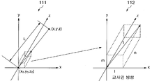
거리센서(21)의 이미 설정된 광투사 지점의 좌표가 도 11의 "111"로 표시된 바와 같이, (x0, y0, z0)로 표시되며, 거리센서(21)가 광을 투사하는 방향의 방향 코사인을 도 11의 "112"에 의해 나타낸 바와 같이 "l", "m", "n"으로 표시한다. 이 경우, 측정점의 좌표들(x, y, z)은 다음 식(20)으로 나타내진다. 도 11의 "L"은 프로젝터(1)와 거리 데이터에 기초하여 얻어진 측정점 사이의 거리를 나타낸다. 광 투사 지점은 능동형 거리센서의 광 방출점을 의미한다.Coordinates of already set light projection points of the
y = y0 + L × m,y = y0 + L × m,
z = z0 + L × nz = z0 + L × n
(2)측정된 점들의 좌표들을 사용하여 광이 그 위에 투사되는 스크린(31)의 스크린 평면을 나타내는 식을 얻는다(2) Using the coordinates of the measured points, we obtain an equation representing the screen plane of the
3개의 측정점들이 있으면, 세 점들의 3차원 좌표들은 각각 (x1, y1, z1), (x2, y2, z2), (x3, y3, z3)이다. 이 경우, 식(17)에 따라 스크린 평면을 나타내는 다음의 연립 방정식인 식(21)이 형성된다.If there are three measurement points, the three-dimensional coordinates of the three points are (x1, y1, z1), (x2, y2, z2), (x3, y3, z3), respectively. In this case, equation (21) is formed according to equation (17) which is the following simultaneous equations representing the screen plane.

이 연립방정식(21)을 풀면, 계수들(a, b, c)은 다음 식(22)으로 나타내진다.Solving this system of


3개 이상의 측정점들이 존재하면, 스크린 평면의 개략적인 해상도가 최소-사각(least-square) 방법에 의하여 얻어질 수 있다.If there are three or more measurement points, the coarse resolution of the screen plane can be obtained by means of the least-square method.
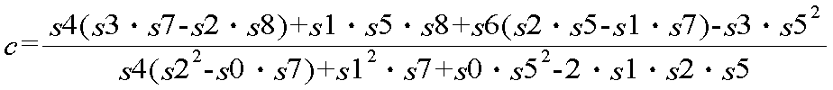
이 경우, 측정점의 좌표들이 (xi, yi, zi)라고 하면, s0, ... , s8이 식(23)에 의해 얻어진다.In this case, if the coordinates of the measuring points are (xi, yi, zi), s0, ..., s8 are obtained by equation (23).

3개 이상의 측정점들이 있는 경우, 스크린 평면은 식(23)으로부터 얻은 s0, ... , s8을 사용하여 다음의 식(24)으로 나타내진다.If there are three or more measurement points, the screen plane is represented by the following equation (24) using s0, ..., s8 obtained from equation (23).

식(24)을 계수들(a, b, c)에 대해 풀면, 이들 계수들은 다음 식(25)으로 나타내진다.Solving equation (24) with respect to coefficients (a, b, c), these coefficients are represented by the following equation (25).


3개의 측정점들이 있으면, 식(24)를 푸는 것이 연립방정식(21)을 푸는 것과 같다.If there are three measuring points, solving equation (24) is equivalent to solving the system of equations (21).
(3)경사각들(θH 및 θV)을 획득(3) Obtain the inclination angles θ H and θ V
경사각들(θH 및 θV)은 상기 식(19)을 통해 얻어진다. Tilt angles θ H and θ V are obtained through equation (19) above.
상기 설명한 바와 같이, 경사각들(θH 및 θV)은 식(19 내지 25)을 사용하여 복수의 거리 데이터들에 기초하여 얻어질 수 있다. As described above, the inclination angles θ H and θ V can be obtained based on a plurality of distance data using equations (19-25).
스크린 식의 산출유닛(24)은 식(20 내지 25)에 따라 계수들("a", "b")을 산출하고, 산출된 계수들("a", "b")을 경사각 산출유닛(25)에 공급한다. The screen
경사각 산출유닛(25)은 식(19)에 따라 공급된 계수들("a", "b")을 사용하여 경사각들(θH 및 θV)을 산출한다. 각도 산출유닛(23)은 경사각 산출유닛(25)에 의하여 산출된 경사각들(θH 및 θV)을 사다리형 정정유닛(12)에 공급한다.The inclination
각도산출유닛(23)은 식(19 내지 25)에 따라 경사각들(θH 및 θV)을 미리 산출하도록 구성될 수 있다. 이러한 경우, 경사각 산출유닛(25)은 메모리를 구비하고, 복수의 거리 데이터들을 경사각들(θH 및 θV)에 결합시키기 위한 식(19 내지 25)에 따른 미리 생성된 해석표를 메모리에 저장한다. The
다음에, 제 1 실시예에 따른 프로젝터(1)의 작동이 설명된다.Next, the operation of the
제어유닛(22)의 제어 하에서, 스크린 각도센서(16)의 거리센서(21)는 프로젝터(1)와 스크린(31) 위의 복수 지점들 사이의 거리를 측정한다. 거리센서(21)는 거리 측정 결과를 나타내는 거리 데이터를 각도 산출유닛(23)에 공급한다. Under the control of the
상기 설명한 바와 같이, 각도 산출유닛(23)의 스크린의 식 산출유닛(24)은 식들(20 내지 25)에 따라 계수들(a, b)을 산출한다. 경사각 산출유닛(25)은 식(19)와 산출된 계수들(a, b)을 사용하여 스크린(31)의 경사각들(θH 및 θV)을 산출한다.As described above, the
각도 산출유닛(23)은 경사각 산출유닛(25)에 의하여 산출된 경사각들(θV 및 θH)을 사다리형 정정유닛(12)에 공급한다. The
사다리형 정정유닛(12)에 경사각들(θV 및 θH)이 공급되면, 스케일러(11)는 이미지 신호의 해상도를 조정하며, 사다리형 정정유닛(12)에 조정된 이미지 신호를 공급한다.When the inclination angles θ V and θ H are supplied to the
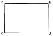
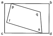
이미지를 도 12A에 도시된 사각형(abcd)으로 상정한다. 이러한 경우, 사다리형 정정유닛(12)은 스크린 각도센서(16)로부터 공급된 경사각들(θH 및 θV)에 기초하여 이 사각형(abcd)에 대해 사다리형 정정을 수행한다. The image is assumed to be an abcd shown in FIG. 12A. In this case, the
사다리형 정정유닛(12)은 공급된 경사각들(θH 및 θV) 및 스크린의 평면을 나타내는 식을 사용하여 산출된 경사각들(θH 및 θV)을 투사 이미지용 정정량과 결합시키는 해석표를 사용함으로써 투사 이미지용의 정정량을 획득한다.Ladder-
그러나, 상기 설명한 바와 같이, 사다리형 정정유닛(12)은 해석표를 사용함이 없이 경사각들(θH 및 θV)이 공급될 때마다 사다리형 정정을 수행할 수 있다. However, as described above, the
사다리형 정정유닛(12)은 스크린(31) 위에 투사된 이미지를 사용하여 얻어진 정정량에 기초하여 정정 결과로서 얻어지는 투사 이미지의 위치 및 형상을 결정한다. 이어서, 사다리형 정정유닛(12)은 이미지 신호를 임시로 연속해서 돌출 변형시킴으로써 사다리형 정정을 수행한다.The
사다리형 정정유닛(12)에 의하여 수행된 사다리형 정정의 결과로서, 도 12A 및 도 12C에 도시된 사각형(abcd)은 도 12C에 도시된 사각형(pqrs)으로 정정된다.As a result of the ladder correction performed by the
광변조유닛(13)은 사다리형 정정유닛(12)에 의한 정정 후에 얻어지며 도 12C의 사각형(pqrs)을 나타내는 이미지 신호를 투사광으로 변환시킨다. 광변조유닛(13)에 의하여 전환되어 얻어진 투사광은 경사각(θH 및 θV) 만큼 경사진 스크린(31) 위에 투사된다. 따라서, 사다리형 정정 후의 투사 이미지, 즉 도 12B에 도시된 사각형(p'q'r's')이 스크린(31) 위에 투사된다. 도 12B에 도시된 정정 전의 사각형(a'b'c'd')은 사다리형 정정유닛(12)이 사다리형 정정을 수행하지 않는 경우의 투사 이미지이다. The
프로젝터(1)가 확대 기구를 가지면, 광학기구(15)는 확대 제어를 수행하며 확대 배율에 대한 정보를 사다리형 정정유닛(12)으로 공급한다. 이러한 경우, 사다 리형 정정유닛(12)은 경사각들(θH 및 θV) 및 확대 배율에 기초하여 사다리형 정정을 수행한다.When the
프로젝터(1)가 투사렌즈(14)를 통하여 스크린(31) 위에 도 12C에 도시된 사각형(pqrs)을 투사하면, 도 12B에 도시된 사각형(p'q'r's')이 스크린(31) 위에 표시된다.When the
상기 설명한 바와 같이, 제 1 실시예에 따르면, 프로젝터(1)와 스크린(31) 위의 복수의 측정점들 사이의 거리들은 거리센서(21)를 사용하여 측정된다. 스크린 평면을 나타내는 식이 이어서 측정된 거리들에 기초하여 유도되며 경사각들(θH 및 θV)이 얻어진다.As described above, according to the first embodiment, the distances between the
따라서, 가속센서의 사용없이 경사각들(θH 및 θV)이 얻어질 수 있다. 즉, 지표면에 대해 스크린의 경사각을 산출함이 없이 사다리형 정정을 수행할 수 있다. 또한, 스크린(31)이 광축에 대해 수평 방향으로 경사진 경우 및 스크린(31)이 수평 방향 및 수직 방향으로 경사진 경우에 사다리형 정정을 정확하게 수행할 수 있다.Thus, the inclination angles θ H and θ V can be obtained without the use of an acceleration sensor. That is, the ladder correction can be performed without calculating the inclination angle of the screen with respect to the ground surface. Further, ladder correction can be accurately performed when the
(제 2 실시예)(Second embodiment)
제 2 실시예에 따른 프로젝터는 프로젝터와 스크린 위의 수평 방향으로 배치된 복수의 측정점들 사이의 거리 및 프로젝터와 스크린 위에서 수직 방향으로 배치된 복수의 측정점들 사이의 거리를 측정하기 위한 두개의 거리센서들을 구비하고, 이들 센서들을 이용하여 경사각들을 획득한다.The projector according to the second embodiment includes two distance sensors for measuring the distance between the projector and the plurality of measuring points arranged in the horizontal direction on the screen and the distance between the projector and the plurality of measuring points arranged in the vertical direction on the screen. And tilt angles are obtained using these sensors.
제 2 실시예에 따른 프로젝터(1)의 구조가 도 1에 도시된다.The structure of the
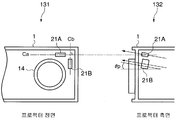
제 2 실시예에 따른 프로젝터(1)는 거리센서들로서, 거리센서(21A)와 거리센서(21B)를 구비하는데, 이들은 도 13에서는 (131, 132)로 표시된다. The
거리센서들(21A, 21B)은 모두 복수 방향으로 거리를 측정할 수 있는 다중 측정 기능을 가진 위상차 센서들로서 예컨대, AF 모듈로서 구성된다.The
거리센서들(21A, 21B)은 도 13의 부호(131)로서 나타낸 바와 같이, 각각의 중심선(Ca, Cb)이 수직으로 교차하도록 투사렌즈 근처에 배치된다. 거리센서들(21A, 21B)은 프로젝터(1)와 각각의 중심선(Ca, Cb)에 대응하는 스크린 위의 측정선들 위에 배치된 복수의 측정점들 사이의 거리들을 측정한다.The
도 13에서 부호(132)로 표시한 바와 같이, 프로젝터(1)의 투삭광의 광축에 대해 거리센서들(21A, 21B)의 상승 각도는 θP로 상정된다. 상승각도(θP )는 양의 값 또는 음의 값을 가지며, 0일 수 있다. As indicated by
제 2 실시예에 따른 각도산출유닛(23)은 도 14에 도시된 바와 같이, 경사각 산출유닛(25) 및 각도 해석유닛(26)을 구비한다.As shown in FIG. 14, the
제 2 실시예에 따른 경사각 산출유닛(25)은 거리센서들(21A, 21B)에 의하여 수행된 측정 결과를 나타내는 거리에 기초하여 경사각들(θA 및 θB)을 산출한다. 경사각들(θA 및 θB)은 각각 중심선들(Ca, Cb)에 대한 스크린(31)의 경사각이다. The inclination
프로젝터(1)와 중심선들(Ca, Cb)에 대응하는 측정선들 위에 배치된 복수의 측정점들 사이의 거리들이 측정될 수 있으면, 스크린(31)의 수평 방향 및 수직 방향의 경사각들이 얻어질 수 있다. If the distances between the
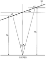
경사각들의 획득 원리가 도 15와 관련하여 이제 설명된다.The principle of obtaining the tilt angles is now described with reference to FIG. 15.
프로젝터(1)로부터 방출된 투사광의 광축에 대한 스크린(31)의 경사각(θS)는 다음 식(26)에 의하여 표시된다.The inclination angle θ S of the

(DR은 프로젝터(1)와 측정선 위의 측정점(P1) 사이의 거리, DL은 프로젝터(1)와 측정선 위의 측정점(P2) 사이의 거리, θW는 프로젝터(1)로부터의 투사광의 광축과 측정점(P1)과 프로젝터(1)의 연결선 사이에 형성된 각도이며, 프로젝터(1)와 측정점(P2)을 연결하는 선과 광축 사이에 형성되는 각도이다)(D R is the distance between the
거리센서(21A)의 측정 결과로부터 얻어진 경사각(θS)이 θA이고, 거리센서(21b)의 측정 결과로부터 얻어진 경사각(θS)이 θB라고 상정된다. 거리센서들(21A, 21B)은 중심선들(Ca, Cb)이 수직으로 교차하도록 배치되므로 거리센서들(21A, 21B)의 측정선들은 수직으로 교차한다. 따라서, 경사각들(θA 및 θB)에 기초하여 다음 식(27)에 따라 경사각들(θV 및 θH)이 산출될 수 있다.It is assumed that the inclination angle θ S obtained from the measurement result of the
![]()
![]()
![]()
![]()
경사각 산출유닛(25)은 식(26)에 따라 경사각들(θA 및 θB)을 산출하며, 각도 해석유닛(26)은 식(27)에 따라 경사각들(θV 및 θH)을 산출한다.The inclination
각도 해석유닛(26)은 경사각 산출유닛(25)에 의하여 산출된 경사각들(θA 및 θB)을 각각 식(27)에 따라 경사각들(θV 및 θH)로 해석한다. 이로써, 각도 해석유닛(26)은 경사각들(θV 및 θH)을 얻는다.The
각도 산출유닛(23)은 각도 해석유닛(26)에 의하여 산출된 경사각들(θV 및 θH)을 사다리형 정정유닛(12)에 공급한다.The
다음에는 제 2 실시예에 따른 프로젝터(1)의 작동이 설명된다.Next, the operation of the
제어유닛(22)은 프로젝터(1)와 수평 방향으로 배치된 복수의 측정점들 사이의 거리들을 측정하기 위한 거리센서(21A)를 제어한다.The
또한, 제어유닛(22)은 프로젝터(1)와 수직 방향으로 배치된 복수의 측정점들 사이의 거리들을 측정하기 위한 거리센서(21B)를 제어한다. In addition, the
거리센서들(21A, 21B)은 프로젝터(1)와 각각의 측정점들 사이의 측정된 거리를 나타내는 거리 데이터를 각도산출유닛(23)에 공급한다.The
각도산출유닛(23)의 경사각 산출유닛(25)은 거리센서들(21A, 21B)에서 공급된 거리 데이터에 기초하여 식(26)을 사용하여 경사각들(θA 및 θB)을 산출한다.The inclination
각도해석유닛(26)은 식(27)에 따라 경사각들(θA 및 θB)을 경사각들(θV 및 θH)로 해석한다.The
각도산출유닛(23)은 각도해석유닛(26)에 의하여 산출된 경사각들(θV 및 θH)을 사다리형 정정유닛(12)에 공급한다.The
사다리형 정정유닛(12)은 각도산출유닛(23)에서 공급된 경사각들(θV 및 θH)에 기초하여 투사 이미지의 왜곡을 정정한다.The
상기 설명한 바와 같이, 제 2 실시예에 따르면, 2개의 거리센서들(21A, 21B)은 프로젝터(1)와 스크린(31) 위에서 수직으로 교차하는 측정선들 위에 배치된 복수의 측정점들 사이의 거리들을 측정한다. 각도산출유닛(23)은 복수의 거리 데이터들에 기초하여 경사각들(θV 및 θH)을 산출한다.As described above, according to the second embodiment, the two
그러므로, 복수 방향에서의 거리를 각각 측정할 수 있는 2개의 거리센서들(21A, 21B)을 구비함으로써 수평 방향 및 수직 방향의 경사각들(θV 및 θH)을 산출할 수 있으며, 센서들의 숫자를 감소시켜 프로젝터를 축소할 수 있다. 또한, 저가로 프로젝터(1)를 제조할 수 있다. 또한, 거리센서들(21A, 21B)을 사용함으로써, 거리 측정 패턴이 투사렌즈들(14)을 통하여 투사될 수 있으며, 측정 정밀도를 향상시킬 수 있다. Therefore, the inclination angles θ V and θ H in the horizontal and vertical directions can be calculated by providing two
본 발명을 구현하기 위하여 상기 설명한 제 1, 2 실시예들 외에 여러 실시예들이 고려될 수 있다.Various embodiments may be considered in order to implement the present invention in addition to the first and second embodiments described above.
예컨대, 상기 설명한 제 1, 2 실시예들에서, 프로젝터(1)는 거리센서들(21A, 21B) 외에 가속센서를 구비할 수 있다. 프로젝터(1)는 거리센서들(21A, 21B)에 의하여 거리가 정확하게 측정될 수 없으면, 수직 방향의 경사각(θV)에 기초하여 가속센서를 사용하여 사다리형 정정을 수행하도록 구성될 수 있다.For example, in the first and second embodiments described above, the
또한, 상기 설명한 실시예들에서, 프로젝터(1)의 중심에 원점을 설정하거나 스크린(31)의 평면 위에 설정한 3차원 직교 좌표계를 사용하여 설명이 이루어졌다. 그러나, 프로젝터(1)와 스크린(31)이 3차원 직교 좌표계에 의하여 규정되는 공간에 존재하는 한, 원점이 설정되는 위치에 무관하게 경사각들(θV 및 θH)이 얻어질 수 있다. 또한, 3차원 직교 좌표계를 사용함이 없이, 예컨대, 극좌표계를 사용하여 유사하게 경사각들(θV 및 θH)이 얻어질 수 있다.In addition, in the above-described embodiments, the explanation has been made using a three-dimensional rectangular coordinate system set at the center of the
본 발명의 광범위한 사상과 범위를 벗어남이 없이 본 발명에 대해 여러 실시예들과 변화들이 이루어질 수 있다. 상기 설명한 실시예들은 본 발명을 설명하기 위함이며, 본 발명의 범위를 제한하기 위한 것이 아니다. 본 발명의 범위는 실시예들에 의해서 보다 첨부의 청구범위들에 의하여 표현된다. 본 발명의 청구항들의 균등물의 의미 내에서 그리고 청구항들 내에서 이루어진 여러 변형들은 본 발명의 범위 내에 속하는 것으로 간주된다.Various embodiments and changes may be made to the present invention without departing from the broad spirit and scope of the invention. The above described embodiments are intended to illustrate the present invention and are not intended to limit the scope of the present invention. The scope of the invention is represented by the appended claims rather by the embodiments. Various modifications made within the meaning of the equivalents of the claims of the invention and within the claims are considered to be within the scope of the invention.
따라서, 본 발명에 따르면, 스크린 위에 표시되는 투사 이미지를 정확하게 정정할 수 있다.Thus, according to the present invention, the projection image displayed on the screen can be corrected accurately.
Claims (10)


Applications Claiming Priority (2)
| Application Number | Priority Date | Filing Date | Title |
|---|---|---|---|
| JP2003275004A JP4155890B2 (en) | 2003-07-15 | 2003-07-15 | Projector, projector tilt angle acquisition method, and projection image correction method |
| JPJP-P-2003-00275004 | 2003-07-15 |
Publications (2)
| Publication Number | Publication Date |
|---|---|
| KR20060031685A KR20060031685A (en) | 2006-04-12 |
| KR100835759B1 true KR100835759B1 (en) | 2008-06-05 |
Family
ID=34056108
Family Applications (1)
| Application Number | Title | Priority Date | Filing Date |
|---|---|---|---|
| KR1020067000923A KR100835759B1 (en) | 2003-07-15 | 2004-07-13 | Image projector, inclination angle detection method, and projection image correction method |
Country Status (7)
| Country | Link |
|---|---|
| US (1) | US7131732B2 (en) |
| EP (1) | EP1645119A2 (en) |
| JP (1) | JP4155890B2 (en) |
| KR (1) | KR100835759B1 (en) |
| CN (1) | CN1823523B (en) |
| TW (1) | TWI278714B (en) |
| WO (1) | WO2005006073A2 (en) |
Cited By (1)
| Publication number | Priority date | Publication date | Assignee | Title |
|---|---|---|---|---|
| KR101230463B1 (en) | 2010-01-07 | 2013-02-06 | 세이코 엡슨 가부시키가이샤 | Projector and method of controlling the same |
Families Citing this family (70)
| Publication number | Priority date | Publication date | Assignee | Title |
|---|---|---|---|---|
| JP2005006228A (en) * | 2003-06-13 | 2005-01-06 | Casio Comput Co Ltd | Projector |
| JP4155890B2 (en) | 2003-07-15 | 2008-09-24 | カシオ計算機株式会社 | Projector, projector tilt angle acquisition method, and projection image correction method |
| JP3969363B2 (en) * | 2003-07-30 | 2007-09-05 | カシオ計算機株式会社 | Projector and projection image correction method for projector |
| TWI244336B (en) * | 2003-08-08 | 2005-11-21 | Casio Computer Co Ltd | Projector and compensation method for image projected |
| US7137707B2 (en) * | 2004-07-01 | 2006-11-21 | Mitsubishi Electric Research Laboratories, Inc | Projector-camera system with laser pointers |
| US7262816B2 (en) * | 2004-10-22 | 2007-08-28 | Fakespace Labs, Inc. | Rear projection imaging system with image warping distortion correction system and associated method |
| JP2006242833A (en) * | 2005-03-04 | 2006-09-14 | Nidec Copal Corp | Device for detecting optical angle |
| CN101923277B (en) | 2005-04-28 | 2012-07-18 | 株式会社日立制作所 | Projection type image display device |
| JP4454543B2 (en) * | 2005-06-23 | 2010-04-21 | Necディスプレイソリューションズ株式会社 | Projector with distortion correction means |
| JP2007067495A (en) * | 2005-08-29 | 2007-03-15 | Toshiba Corp | Projector |
| US7706573B1 (en) * | 2005-09-19 | 2010-04-27 | Motamedi Manouchehr E | Remote distance-measurement between any two arbitrary points using laser assisted optics |
| US20070182936A1 (en) * | 2006-02-08 | 2007-08-09 | Canon Kabushiki Kaisha | Projection display apparatus |
| JP2007311904A (en) * | 2006-05-16 | 2007-11-29 | Victor Co Of Japan Ltd | Drive recorder, video image correction method thereof, drive recorder, and system thereof |
| JP4872525B2 (en) * | 2006-08-14 | 2012-02-08 | カシオ計算機株式会社 | Projector, projector distance measurement method, projector projection plane tilt acquisition method, and program |
| JP4851972B2 (en) * | 2007-03-20 | 2012-01-11 | 富士通株式会社 | Relative position calculation device, relative position adjustment device, relative position adjustment method, and relative position adjustment program |
| JP4785078B2 (en) * | 2007-03-26 | 2011-10-05 | カシオ計算機株式会社 | projector |
| JP4692531B2 (en) | 2007-09-13 | 2011-06-01 | カシオ計算機株式会社 | Projector and optical distance measuring method. |
| JP4600488B2 (en) * | 2008-02-20 | 2010-12-15 | カシオ計算機株式会社 | Projection apparatus and distance measuring method. |
| TWI408489B (en) * | 2008-03-14 | 2013-09-11 | Compal Communications Inc | Projection system and projection method |
| JP5193681B2 (en) * | 2008-05-23 | 2013-05-08 | 三洋電機株式会社 | Portable projector device |
| TWI409519B (en) * | 2008-06-06 | 2013-09-21 | Hon Hai Prec Ind Co Ltd | Inclination angle measurement method for lens module |
| JP5256899B2 (en) * | 2008-07-18 | 2013-08-07 | セイコーエプソン株式会社 | Image correction apparatus, image correction method, projector and projection system |
| JP2011059337A (en) * | 2009-09-09 | 2011-03-24 | Fujifilm Corp | Image pickup apparatus |
| US9030379B2 (en) | 2009-09-11 | 2015-05-12 | Lenovo (Beijing) Co., Ltd. | Display control method for portable terminal and portable terminal |
| JP5353596B2 (en) * | 2009-09-18 | 2013-11-27 | セイコーエプソン株式会社 | Projection display device and keystone correction method |
| JP5409263B2 (en) | 2009-10-28 | 2014-02-05 | 京セラ株式会社 | Mobile electronic device and mobile phone |
| AT509929B1 (en) | 2010-05-21 | 2014-01-15 | Isiqiri Interface Tech Gmbh | PROJECTION DEVICE, AND A METHOD FOR OPERATING THIS PROJECTION DEVICE |
| TW201200953A (en) * | 2010-06-18 | 2012-01-01 | Hon Hai Prec Ind Co Ltd | Projector and adjusting apparatus thereof |
| US8534844B2 (en) * | 2011-01-10 | 2013-09-17 | Lenovo (Singapore) Pte. Ltd. | Dynamic keystone correction |
| JP5730114B2 (en) * | 2011-04-25 | 2015-06-03 | 富士機械製造株式会社 | Component rotation angle detection device, image processing component data creation device, component rotation angle detection method, and image processing component data creation method |
| JP5891714B2 (en) * | 2011-11-02 | 2016-03-23 | 株式会社リコー | Projector and trapezoidal distortion correction method |
| EP2805305B1 (en) | 2012-01-20 | 2017-04-05 | Sick IVP AB | Impact time from image sensing |
| UA77414U (en) * | 2012-08-17 | 2013-02-11 | Александр Григорьевич Беренок | Method for automatic correction of videoprojections by means of inverse transformation |
| JP6201359B2 (en) * | 2013-03-22 | 2017-09-27 | カシオ計算機株式会社 | Projection system, projection method, and projection program |
| CN104349095B (en) * | 2013-08-09 | 2017-08-29 | 联想(北京)有限公司 | A kind of image adjusting method, device and electronic equipment |
| CN103499312B (en) * | 2013-10-22 | 2016-02-24 | 姚雳 | A kind of plane parallelism measurement device |
| CN103974048B (en) * | 2014-04-28 | 2016-05-04 | 京东方科技集团股份有限公司 | The method of control wearable device projection and device, wearable device |
| CN104683724B (en) * | 2015-03-03 | 2019-01-18 | 苏州佳世达光电有限公司 | Projection arrangement and its bearing calibration |
| JP6454573B2 (en) * | 2015-03-17 | 2019-01-16 | 大成建設株式会社 | Measuring method and level difference calculating apparatus using total station |
| CN106331666B (en) * | 2015-07-03 | 2020-02-07 | 中兴通讯股份有限公司 | Projection terminal trapezoidal correction method and device and projection terminal |
| CN106559628A (en) * | 2015-09-28 | 2017-04-05 | 中兴通讯股份有限公司 | A kind of method of projection, device and terminal |
| CN106612422B (en) * | 2015-12-31 | 2018-08-28 | 北京一数科技有限公司 | A kind of projection correction's method and device |
| CN105847773A (en) * | 2016-03-29 | 2016-08-10 | 乐视控股(北京)有限公司 | Method and device used for correcting projected image distortion of projector |
| CN107454372B (en) * | 2016-06-01 | 2021-05-14 | 中兴通讯股份有限公司 | Image correction method and device and projector |
| CN106101676B (en) * | 2016-07-27 | 2019-07-09 | 深圳市Tcl高新技术开发有限公司 | A kind of determination method and system of short focus projector installation site |
| CN106797456B (en) * | 2016-12-30 | 2019-02-01 | 深圳前海达闼云端智能科技有限公司 | Projected picture correcting method, means for correcting and robot |
| CN107147888B (en) * | 2017-05-16 | 2020-06-02 | 深圳市火乐科技发展有限公司 | Method and device for automatically correcting distortion by utilizing graphics processing chip |
| CN107422590B (en) * | 2017-09-12 | 2020-09-08 | 中广热点云科技有限公司 | Household projection system capable of automatically adjusting size of projection surface |
| CN108111828B (en) * | 2017-12-12 | 2019-12-17 | 成都极米科技股份有限公司 | Projection equipment correction method and device and projection equipment |
| GB2570325B (en) * | 2018-01-21 | 2022-04-13 | Arxine Ltd | Immersive display device |
| CN109269444A (en) * | 2018-09-19 | 2019-01-25 | 贵州航天电子科技有限公司 | A kind of servo mechanism angle calibration measurement method |
| CN110262176B (en) * | 2019-06-27 | 2021-06-08 | 成都菲斯特科技有限公司 | Projection screen installation system and installation method |
| CN110381302B (en) * | 2019-08-22 | 2021-10-15 | 歌尔科技有限公司 | Projection pattern correction method, device and system for projection system |
| CN110809141A (en) * | 2019-09-29 | 2020-02-18 | 深圳市火乐科技发展有限公司 | Trapezoidal correction method and device, projector and storage medium |
| KR20210123059A (en) * | 2020-04-02 | 2021-10-13 | 삼성전자주식회사 | Image projecting apparatus and controlling method thereof |
| CN111625151B (en) * | 2020-06-02 | 2023-07-21 | 吕嘉昳 | Method and system for accurately identifying contact point position in deformation projection based on touch method |
| CN111800620A (en) * | 2020-08-18 | 2020-10-20 | 深圳市慧视智图科技有限公司 | Noninductive trapezoidal correction module of projector and calculation method thereof |
| CN114173099A (en) * | 2020-09-11 | 2022-03-11 | 中强光电股份有限公司 | Projection system and projection method |
| TWI755991B (en) * | 2020-12-23 | 2022-02-21 | 陳景昭 | Automatic keystone correction method for projector system |
| TWI768672B (en) | 2021-01-22 | 2022-06-21 | 偉詮電子股份有限公司 | Projector focusing method and projector focusing system |
| US11822225B2 (en) | 2021-03-08 | 2023-11-21 | Samsung Electronics Co., Ltd. | Electronic apparatus and control method thereof |
| WO2022191404A1 (en) * | 2021-03-08 | 2022-09-15 | 삼성전자주식회사 | Electronic device and control method thereof |
| CN115086622A (en) * | 2021-03-12 | 2022-09-20 | 中强光电股份有限公司 | Projector and correction method thereof |
| CN113518212A (en) * | 2021-04-13 | 2021-10-19 | 安徽优品智能科技有限公司 | Trapezoidal correction method and device for projection picture, projection equipment and storage medium |
| CN114812382B (en) * | 2021-04-14 | 2023-11-28 | 成都极米科技股份有限公司 | Multi-point measuring method and device for projection surface, storage medium and projection equipment |
| KR20230105622A (en) * | 2022-01-04 | 2023-07-11 | 삼성전자주식회사 | An electronic apparatus and method for controlling thereof |
| CN114518080A (en) * | 2022-02-17 | 2022-05-20 | 上海复诺视觉智能科技有限公司 | Device and method for correcting perpendicularity between test equipment and screen to be tested |
| CN114745529A (en) * | 2022-03-30 | 2022-07-12 | 深圳市橙子数字科技有限公司 | Projector single TOF trapezoidal correction method and projector |
| CN117255184B (en) * | 2023-11-17 | 2024-03-08 | 深圳市橙子数字科技有限公司 | Correction method for side projection blur of projector |
| CN117570853B (en) * | 2024-01-16 | 2024-04-09 | 深圳新智联软件有限公司 | Method, device, equipment and storage medium for calculating four-point coordinates in projection interface |
Citations (2)
| Publication number | Priority date | Publication date | Assignee | Title |
|---|---|---|---|---|
| JPH089309A (en) * | 1994-06-23 | 1996-01-12 | Canon Inc | Display method and its device |
| JP2002108322A (en) * | 2000-09-27 | 2002-04-10 | Shadow Entertainment Inc | Projection system and projecting method |
Family Cites Families (30)
| Publication number | Priority date | Publication date | Assignee | Title |
|---|---|---|---|---|
| JPH04181935A (en) | 1990-11-16 | 1992-06-29 | Canon Inc | Optical device having automatic focus detecting means |
| JPH04355740A (en) | 1991-06-03 | 1992-12-09 | Hitachi Ltd | Projector |
| EP0611125B1 (en) * | 1993-02-12 | 2000-11-22 | Sony Corporation | Electronic zoom control and image stabilization |
| JPH09197249A (en) | 1996-01-17 | 1997-07-31 | Nikon Corp | Liquid crystal projector |
| US6230070B1 (en) | 1997-07-23 | 2001-05-08 | Fuji Seiki Co., Ltd. | Work position adjusting apparatus and adjusting method |
| US6741279B1 (en) | 1998-07-21 | 2004-05-25 | Hewlett-Packard Development Company, L.P. | System and method for capturing document orientation information with a digital camera |
| CN1210944C (en) | 1998-10-02 | 2005-07-13 | 旺宏电子股份有限公司 | Method and device for preventing keystone distortion |
| TW399163B (en) | 1999-11-19 | 2000-07-21 | Acer Peripherals Inc | Rear projector with adjustable image size and its method |
| JP2001186538A (en) * | 1999-12-27 | 2001-07-06 | Toshiba Corp | Video projector |
| JP2001230991A (en) | 2000-02-15 | 2001-08-24 | Seiko Epson Corp | Projector and image processor used therefor |
| JP2001311619A (en) | 2000-05-01 | 2001-11-09 | Asahi Optical Co Ltd | Apparatus and method for measuring distance |
| JP2001339671A (en) | 2000-05-29 | 2001-12-07 | Matsushita Electric Ind Co Ltd | Projector device |
| JP4961628B2 (en) * | 2000-08-11 | 2012-06-27 | 日本電気株式会社 | Projected image correction system and method |
| US6520647B2 (en) | 2000-08-17 | 2003-02-18 | Mitsubishi Electric Research Laboratories Inc. | Automatic keystone correction for projectors with arbitrary orientation |
| TW480362B (en) | 2000-09-14 | 2002-03-21 | Delta Electronics Inc | Automatic calibration method and device of the projector display |
| WO2002101443A2 (en) | 2001-06-12 | 2002-12-19 | Silicon Optix Inc. | System and method for correcting keystone distortion |
| JP2003029201A (en) * | 2001-07-11 | 2003-01-29 | Canon Inc | Picture projecting device and picture correcting method |
| JP2003153135A (en) | 2001-11-16 | 2003-05-23 | Sanyo Electric Co Ltd | Projection display device |
| DE60327289D1 (en) * | 2002-07-23 | 2009-06-04 | Nec Display Solutions Ltd | Image projector with image feedback control |
| EP1391778A1 (en) | 2002-08-08 | 2004-02-25 | Seiko Precision Inc. | Apparatus for detecting the inclination angle of a projection screen and projector comprising the same |
| JP2004093275A (en) * | 2002-08-30 | 2004-03-25 | Seiko Precision Inc | Angle detection device and projector having the same |
| EP1426732A1 (en) * | 2002-11-29 | 2004-06-09 | Seiko Precision Inc. | Angle detection apparatus, projector including the same, and angle detection method |
| JP4508553B2 (en) | 2003-06-02 | 2010-07-21 | カシオ計算機株式会社 | Captured image projection device and captured image correction method |
| JP2005006228A (en) * | 2003-06-13 | 2005-01-06 | Casio Comput Co Ltd | Projector |
| JP4155890B2 (en) | 2003-07-15 | 2008-09-24 | カシオ計算機株式会社 | Projector, projector tilt angle acquisition method, and projection image correction method |
| JP3969363B2 (en) | 2003-07-30 | 2007-09-05 | カシオ計算機株式会社 | Projector and projection image correction method for projector |
| JP3827662B2 (en) | 2003-09-10 | 2006-09-27 | Necビューテクノロジー株式会社 | Projection display |
| JP3770609B2 (en) | 2003-10-14 | 2006-04-26 | Necビューテクノロジー株式会社 | Projector and distortion correction method |
| JP2005192188A (en) | 2003-12-03 | 2005-07-14 | Seiko Epson Corp | Projector |
| JP2005227661A (en) | 2004-02-16 | 2005-08-25 | Nec Viewtechnology Ltd | Projector and method of correcting distortion |
-
2003
- 2003-07-15 JP JP2003275004A patent/JP4155890B2/en not_active Expired - Fee Related
-
2004
- 2004-07-12 US US10/890,567 patent/US7131732B2/en active Active
- 2004-07-13 CN CN2004800202934A patent/CN1823523B/en not_active Expired - Fee Related
- 2004-07-13 EP EP04747731A patent/EP1645119A2/en not_active Ceased
- 2004-07-13 KR KR1020067000923A patent/KR100835759B1/en active IP Right Grant
- 2004-07-13 WO PCT/JP2004/010267 patent/WO2005006073A2/en active Application Filing
- 2004-07-14 TW TW093120932A patent/TWI278714B/en not_active IP Right Cessation
Patent Citations (2)
| Publication number | Priority date | Publication date | Assignee | Title |
|---|---|---|---|---|
| JPH089309A (en) * | 1994-06-23 | 1996-01-12 | Canon Inc | Display method and its device |
| JP2002108322A (en) * | 2000-09-27 | 2002-04-10 | Shadow Entertainment Inc | Projection system and projecting method |
Cited By (1)
| Publication number | Priority date | Publication date | Assignee | Title |
|---|---|---|---|---|
| KR101230463B1 (en) | 2010-01-07 | 2013-02-06 | 세이코 엡슨 가부시키가이샤 | Projector and method of controlling the same |
Also Published As
| Publication number | Publication date |
|---|---|
| WO2005006073A3 (en) | 2005-06-02 |
| TW200517761A (en) | 2005-06-01 |
| JP2005039558A (en) | 2005-02-10 |
| JP4155890B2 (en) | 2008-09-24 |
| KR20060031685A (en) | 2006-04-12 |
| CN1823523B (en) | 2010-12-08 |
| US20050012907A1 (en) | 2005-01-20 |
| TWI278714B (en) | 2007-04-11 |
| CN1823523A (en) | 2006-08-23 |
| US7131732B2 (en) | 2006-11-07 |
| WO2005006073A2 (en) | 2005-01-20 |
| EP1645119A2 (en) | 2006-04-12 |
Similar Documents
| Publication | Publication Date | Title |
|---|---|---|
| KR100835759B1 (en) | Image projector, inclination angle detection method, and projection image correction method | |
| US7454054B2 (en) | Three-dimensional shape input device | |
| US6416186B1 (en) | Projection display unit | |
| JP5257616B2 (en) | Projector, program, information storage medium, and trapezoidal distortion correction method | |
| JP4435145B2 (en) | Method and apparatus for providing panoramic image by calibrating geometric information | |
| JP4356050B2 (en) | Surveyor and electronic storage medium | |
| CN102025951B (en) | Projection display device and keystone correction method | |
| JP4961628B2 (en) | Projected image correction system and method | |
| US20080129894A1 (en) | Geometric calibration apparatus for correcting image distortions on curved screen, and calibration control system and method using the same | |
| US20090138233A1 (en) | Surveying Instrument and Method of Providing Survey Data of a Target Region Using a Surveying Instrument | |
| US20140081570A1 (en) | Graphics-aided remote position measurement with handheld geodesic device | |
| US10877155B2 (en) | Survey data processing device, survey data processing method, and survey data processing program | |
| JP2004163292A (en) | Survey system and electronic storage medium | |
| US8633983B2 (en) | Feature detection apparatus and method for measuring object distances | |
| JP2010122273A (en) | Method of measuring zoom ratio of projection optical system, method of correcting projection image using the method, and projector executing the correction method | |
| KR102093622B1 (en) | Method and apparatus for real-time correction of projector image using depth camera | |
| US20190285404A1 (en) | Noncontact three-dimensional measurement system | |
| CN114286068A (en) | Focusing method, focusing device, storage medium and projection equipment | |
| KR20010009721A (en) | Non-contact type 3D scarmer 3 dimensional | |
| JP5561503B2 (en) | Projector, program, information storage medium, and trapezoidal distortion correction method | |
| CN110141800A (en) | A kind of accelerator light carpenters square equipment, scaling method and optical moment ruler generation method | |
| US10403002B2 (en) | Method and system for transforming between physical images and virtual images | |
| JP2002296673A (en) | Image projection device | |
| JP2023546037A (en) | image recording device | |
| CN116033131B (en) | Image correction method, device, electronic equipment and readable storage medium |
Legal Events
| Date | Code | Title | Description |
|---|---|---|---|
| A201 | Request for examination | ||
| E902 | Notification of reason for refusal | ||
| E902 | Notification of reason for refusal | ||
| E701 | Decision to grant or registration of patent right | ||
| GRNT | Written decision to grant | ||
| FPAY | Annual fee payment |
Payment date: 20130503 Year of fee payment: 6 |
|
| FPAY | Annual fee payment |
Payment date: 20140507 Year of fee payment: 7 |
|
| FPAY | Annual fee payment |
Payment date: 20150526 Year of fee payment: 8 |
|
| FPAY | Annual fee payment |
Payment date: 20160427 Year of fee payment: 9 |
|
| FPAY | Annual fee payment |
Payment date: 20170504 Year of fee payment: 10 |
|
| FPAY | Annual fee payment |
Payment date: 20180517 Year of fee payment: 11 |
|
| FPAY | Annual fee payment |
Payment date: 20190515 Year of fee payment: 12 |