KR100739511B1 - Apparatus and method for transmitting/receiving pilot signal in a communication system using orthogonal frequency division multiplexing scheme - Google Patents
Apparatus and method for transmitting/receiving pilot signal in a communication system using orthogonal frequency division multiplexing scheme Download PDFInfo
- Publication number
- KR100739511B1 KR100739511B1 KR1020040067648A KR20040067648A KR100739511B1 KR 100739511 B1 KR100739511 B1 KR 100739511B1 KR 1020040067648 A KR1020040067648 A KR 1020040067648A KR 20040067648 A KR20040067648 A KR 20040067648A KR 100739511 B1 KR100739511 B1 KR 100739511B1
- Authority
- KR
- South Korea
- Prior art keywords
- reference signal
- transmitting
- sector
- cell
- identifier
- Prior art date
Links
Images


Classifications
-
- H—ELECTRICITY
- H04—ELECTRIC COMMUNICATION TECHNIQUE
- H04L—TRANSMISSION OF DIGITAL INFORMATION, e.g. TELEGRAPHIC COMMUNICATION
- H04L27/00—Modulated-carrier systems
- H04L27/26—Systems using multi-frequency codes
- H04L27/2601—Multicarrier modulation systems
- H04L27/2602—Signal structure
- H04L27/261—Details of reference signals
- H04L27/2613—Structure of the reference signals
-
- H—ELECTRICITY
- H04—ELECTRIC COMMUNICATION TECHNIQUE
- H04L—TRANSMISSION OF DIGITAL INFORMATION, e.g. TELEGRAPHIC COMMUNICATION
- H04L5/00—Arrangements affording multiple use of the transmission path
- H04L5/003—Arrangements for allocating sub-channels of the transmission path
- H04L5/0048—Allocation of pilot signals, i.e. of signals known to the receiver
-
- H—ELECTRICITY
- H04—ELECTRIC COMMUNICATION TECHNIQUE
- H04J—MULTIPLEX COMMUNICATION
- H04J11/00—Orthogonal multiplex systems, e.g. using WALSH codes
- H04J11/0069—Cell search, i.e. determining cell identity [cell-ID]
-
- H—ELECTRICITY
- H04—ELECTRIC COMMUNICATION TECHNIQUE
- H04L—TRANSMISSION OF DIGITAL INFORMATION, e.g. TELEGRAPHIC COMMUNICATION
- H04L1/00—Arrangements for detecting or preventing errors in the information received
- H04L1/004—Arrangements for detecting or preventing errors in the information received by using forward error control
- H04L1/0056—Systems characterized by the type of code used
- H04L1/0057—Block codes
-
- H—ELECTRICITY
- H04—ELECTRIC COMMUNICATION TECHNIQUE
- H04L—TRANSMISSION OF DIGITAL INFORMATION, e.g. TELEGRAPHIC COMMUNICATION
- H04L1/00—Arrangements for detecting or preventing errors in the information received
- H04L1/004—Arrangements for detecting or preventing errors in the information received by using forward error control
- H04L1/0056—Systems characterized by the type of code used
- H04L1/0071—Use of interleaving
-
- H—ELECTRICITY
- H04—ELECTRIC COMMUNICATION TECHNIQUE
- H04L—TRANSMISSION OF DIGITAL INFORMATION, e.g. TELEGRAPHIC COMMUNICATION
- H04L1/00—Arrangements for detecting or preventing errors in the information received
- H04L1/004—Arrangements for detecting or preventing errors in the information received by using forward error control
- H04L1/0072—Error control for data other than payload data, e.g. control data
-
- H—ELECTRICITY
- H04—ELECTRIC COMMUNICATION TECHNIQUE
- H04L—TRANSMISSION OF DIGITAL INFORMATION, e.g. TELEGRAPHIC COMMUNICATION
- H04L27/00—Modulated-carrier systems
- H04L27/26—Systems using multi-frequency codes
- H04L27/2601—Multicarrier modulation systems
- H04L27/2614—Peak power aspects
- H04L27/262—Reduction thereof by selection of pilot symbols
-
- H—ELECTRICITY
- H04—ELECTRIC COMMUNICATION TECHNIQUE
- H04L—TRANSMISSION OF DIGITAL INFORMATION, e.g. TELEGRAPHIC COMMUNICATION
- H04L5/00—Arrangements affording multiple use of the transmission path
- H04L5/0001—Arrangements for dividing the transmission path
- H04L5/0026—Division using four or more dimensions
-
- H—ELECTRICITY
- H04—ELECTRIC COMMUNICATION TECHNIQUE
- H04J—MULTIPLEX COMMUNICATION
- H04J13/00—Code division multiplex systems
- H04J13/0007—Code type
- H04J13/004—Orthogonal
- H04J13/0048—Walsh
-
- H—ELECTRICITY
- H04—ELECTRIC COMMUNICATION TECHNIQUE
- H04L—TRANSMISSION OF DIGITAL INFORMATION, e.g. TELEGRAPHIC COMMUNICATION
- H04L27/00—Modulated-carrier systems
- H04L27/0008—Modulated-carrier systems arrangements for allowing a transmitter or receiver to use more than one type of modulation
-
- H—ELECTRICITY
- H04—ELECTRIC COMMUNICATION TECHNIQUE
- H04L—TRANSMISSION OF DIGITAL INFORMATION, e.g. TELEGRAPHIC COMMUNICATION
- H04L27/00—Modulated-carrier systems
- H04L27/18—Phase-modulated carrier systems, i.e. using phase-shift keying
- H04L27/20—Modulator circuits; Transmitter circuits
-
- H—ELECTRICITY
- H04—ELECTRIC COMMUNICATION TECHNIQUE
- H04L—TRANSMISSION OF DIGITAL INFORMATION, e.g. TELEGRAPHIC COMMUNICATION
- H04L27/00—Modulated-carrier systems
- H04L27/26—Systems using multi-frequency codes
- H04L27/2601—Multicarrier modulation systems
- H04L27/2602—Signal structure
- H04L27/261—Details of reference signals
- H04L27/2613—Structure of the reference signals
- H04L27/26132—Structure of the reference signals using repetition
-
- H—ELECTRICITY
- H04—ELECTRIC COMMUNICATION TECHNIQUE
- H04L—TRANSMISSION OF DIGITAL INFORMATION, e.g. TELEGRAPHIC COMMUNICATION
- H04L27/00—Modulated-carrier systems
- H04L27/32—Carrier systems characterised by combinations of two or more of the types covered by groups H04L27/02, H04L27/10, H04L27/18 or H04L27/26
- H04L27/34—Amplitude- and phase-modulated carrier systems, e.g. quadrature-amplitude modulated carrier systems
- H04L27/36—Modulator circuits; Transmitter circuits
- H04L27/362—Modulation using more than one carrier, e.g. with quadrature carriers, separately amplitude modulated
Landscapes
- Engineering & Computer Science (AREA)
- Signal Processing (AREA)
- Computer Networks & Wireless Communication (AREA)
- Databases & Information Systems (AREA)
- Mobile Radio Communication Systems (AREA)
Abstract
각각이 1개 이상의 섹터와 1개 이상의 송신 안테나를 가지는 다수의 셀들을 구비하는 통신 시스템에서, 상기 다수의 셀들 각각은 셀 식별자들 각각으로 구분되며, 상기 다수의 섹터들 각각은 섹터 식별자들 각각으로 구분되며, 상기 셀 식별자 및 섹터 식별자가 입력되면 상기 셀 식별자 및 섹터 식별자에 상응하게 블록 코드 및 왈쉬 코드를 사용하여 제1파트 시퀀스를 생성하고, 미리 설정되어 있는 시퀀스들중 상기 셀 식별자 및 섹터 식별자에 상응하게 제2파트 시퀀스를 선택하고, 상기 제1파트 시퀀스와 상기 제2파트 시퀀스를 사용하여 주파수 영역의 기준 신호로 생성한 후, 상기 주파수 영역의 기준 신호를 역고속 푸리에 변환하여 시간 영역의 기준 신호로 변환한 후, 미리 설정되어 있는 기준 신호 송신 구간에서 상기 시간 영역의 기준 신호를 송신한다.In a communication system having a plurality of cells each having one or more sectors and one or more transmit antennas, each of the plurality of cells is divided into cell identifiers, and each of the plurality of sectors is each of sector identifiers. When the cell identifier and the sector identifier are input, a first part sequence is generated using a block code and a Walsh code corresponding to the cell identifier and the sector identifier, and the cell identifier and the sector identifier among the preset sequences. Selects a second part sequence corresponding to the second part sequence, generates the reference signal in the frequency domain using the first part sequence and the second part sequence, and inversely performs a fast Fourier transform on the reference signal in the frequency domain. After converting into a reference signal, the reference signal of the time domain is transmitted in a preset reference signal transmission interval. The.
파일럿 심벌, PAPR 시퀀스, 셀 ID, 섹터 ID, 블록 부호, 왈쉬 부호Pilot symbol, PAPR sequence, cell ID, sector ID, block code, Walsh code
Description
도 1은 통상적인 OFDM 통신 시스템에서 파일럿 패턴으로 생성 가능한 모든 기울기들을 개략적으로 도시한 도면1 is a view schematically showing all slopes that can be generated in a pilot pattern in a conventional OFDM communication system
도 2는 본 발명의 실시예에 따른 OFDM 통신 시스템의 파일럿 발생기 내부 구조를 도시한 도면2 illustrates an internal structure of a pilot generator of an OFDM communication system according to an embodiment of the present invention.
도 3은 본 발명의 실시예에 따른 OFDM 통신 시스템의 송신기 내부 구조를 도시한 도면3 is a diagram illustrating an internal structure of a transmitter of an OFDM communication system according to an embodiment of the present invention.
도 4는 본 발명의 실시예에 따른 OFDM 통신 시스템의 수신기 내부 구조를 도시한 도면4 is a diagram illustrating an internal structure of a receiver of an OFDM communication system according to an embodiment of the present invention.
도 5는 도 4의 셀 ID/섹터 ID 검출기(419) 내부 구조를 도시한 도면FIG. 5 shows the internal structure of the cell ID /
도 6은 본 발명의 실시예에 따른 OFDM 통신 시스템에서 송신기 동작 과정을 도시한 순서도6 is a flowchart illustrating a transmitter operation process in an OFDM communication system according to an embodiment of the present invention.
도 7은 본 발명의 실시예에 따른 OFDM 통신 시스템에서 수신기 동작 과정을 도시한 순서도7 is a flowchart illustrating a receiver operation process in an OFDM communication system according to an embodiment of the present invention.
도 8은 본 발명의 실시예에 따른 OFDM 통신 시스템에서 IFFT 수행시 서브 캐리어들과 파일럿 심벌과의 매핑 관계를 개략적으로 도시한 도면8 is a diagram schematically illustrating a mapping relationship between subcarriers and pilot symbols when performing an IFFT in an OFDM communication system according to an embodiment of the present invention.
도 9는 본 발명의 실시예에 따른 OFDM 통신 시스템의 시간 영역에서의 파일럿 심벌 구조를 도시한 도면9 illustrates a pilot symbol structure in a time domain of an OFDM communication system according to an embodiment of the present invention.
도 10은 본 발명의 실시예에 따른 OFDM 통신 시스템의 주파수 영역에서의 파일럿 심벌 구조를 도시한 도면
10 illustrates a pilot symbol structure in a frequency domain of an OFDM communication system according to an embodiment of the present invention.
본 발명은 직교 주파수 분할 다중 방식을 사용하는 통신 시스템에 관한 것으로서, 특히 기지국과, 섹터를 구분하기 위한 파일럿 신호 송수신 장치 및 방법에 관한 것이다.The present invention relates to a communication system using orthogonal frequency division multiplexing, and more particularly, to an apparatus and a method for transmitting and receiving pilot signals for distinguishing a base station and a sector.
차세대 통신 시스템인 4세대(4th Generation; 이하 '4G'라 칭하기로 한다) 통신 시스템에서는 고속의 전송 속도를 가지는 다양한 서비스 품질(Quality of Service; 이하 'QoS' 칭하기로 한다)을 가지는 서비스들을 사용자들에게 제공하기 위한 활발한 연구가 진행되고 있다. 특히, 현재 4G 통신 시스템에서는 무선 근거리 통신 네트워크(Local Area Network; 이하 'LAN'이라 칭하기로 한다) 시스템 및 무선 도시 지역 네트워크(Metropolitan Area Network; 이하 'MAN'이라 칭하기로 한 다) 시스템과 같은 광대역 무선 접속(BWA: Broadband Wireless Access) 통신 시스템에 이동성(mobility)과 QoS를 보장하는 형태로 고속 서비스를 지원하도록 하는 연구가 활발하게 진행되고 있다.In the 4th Generation (hereinafter, referred to as '4G') communication system, users of services having various quality of service (hereinafter referred to as 'QoS') having a high transmission rate are used by users. Active research is underway to provide it. In particular, in 4G communication systems, broadband, such as a wireless local area network (hereinafter referred to as "LAN") system and a wireless metropolitan area network (hereinafter referred to as "MAN") system, are widely used. Researches are being actively conducted to support high-speed services in a form of guaranteeing mobility and QoS in a wireless access (BWA) communication system.
그래서, 상기 4G 통신 시스템에서는 유·무선 채널에서 고속데이터 전송에 유용한 방식으로 직교 주파수 분할 다중(OFDM: Orthogonal Frequency Division Multiplexing, 이하 'OFDM'이라 칭하기로 한다) 방식을 활발하게 연구하고 있으며, 상기 OFDM 방식은 멀티-캐리어(multi-carrier)를 사용하여 데이터를 전송하는 방식으로서, 직렬로 입력되는 심벌(symbol)열을 병렬로 변환하여 이들 각각을 상호 직교성을 갖는 다수의 서브 캐리어(sub-carrier)들로 변조하여 전송하는 멀티캐리어 변조(MCM : Multi Carrier Modulation) 방식의 일종이다. Therefore, the 4G communication system is actively studying orthogonal frequency division multiplexing (OFDM) scheme as a method useful for high-speed data transmission in wired and wireless channels. The method uses a multi-carrier to transmit data. A plurality of sub-carriers each having orthogonality to each other by converting serially input symbol strings in parallel. It is a kind of multi-carrier modulation (MCM) that modulates and transmits data.
상기 4G 통신 시스템이 고속, 고품질의 무선 멀티미디어 서비스를 제공하기 위해서는 광대역의 스펙트럼(spectrum) 자원이 필요하다. 하지만, 광대역 스펙트럼 자원을 사용할 경우에는 다중 경로 전파(multipath propagation)에 따른 무선 전송로 상에서의 페이딩(fading) 영향이 심각해지며, 전송 대역 내에서도 주파수 선택적 페이딩(frequency selective fading)에 따른 영향이 발생한다. 따라서, 고속의 무선 멀티미디어 서비스를 위해서는 부호 분할 다중 접속(CDMA: Code 야vision Multiple Access, 이하 'CDMA'라 칭하기로 한다) 방식에 비해 주파수 선택적 페이딩에 강인한 OFDM 방식이 더 큰 이득을 가지므로 상기 4G 통신 시스템에 적극 활용되고 있는 추세에 있다.Broadband spectrum resources are required for the 4G communication system to provide high speed, high quality wireless multimedia services. However, when the broadband spectrum resource is used, fading effects on the radio transmission path due to multipath propagation become serious and frequency selective fading also occurs within the transmission band. Therefore, the OFDM scheme, which is robust against frequency selective fading, has greater gain than the code division multiple access (CDMA) scheme for high-speed wireless multimedia services. There is a trend of being actively used in communication systems.
그러면 여기서, 상기 OFDM 방식을 사용하는 통신 시스템(이하 'OFDM 통신 시 스템'이라 칭하기로 한다)의 송신기와 수신기의 동작을 간략하게 살펴보면 다음과 같다.Here, the operation of the transmitter and the receiver of the communication system using the OFDM scheme (hereinafter referred to as 'OFDM communication system') will be briefly described as follows.
상기 OFDM 통신 시스템의 송신기에서 입력 데이터는 스크램블러(scrambler), 인코더(encoder), 인터리버(interleaver)를 통해서 서브 캐리어들로 변조된다. 이때, 상기 송신기는 다양한 가변 데이터 전송율(data rate)을 제공하는데, 상기 데이터 전송율에 따라서 각기 다른 부호화율(coding rate)과, 인터리빙 크기(interleaving size) 및 변조 방식을 갖게 된다. 통상적으로 상기 인코더는 1/2, 3/4 등의 부호화율을 사용하고, 버스트 에러(burst error)를 방지하기 위한 인터리버의 크기는 OFDM 심벌당 부호화된 비트 수(NCBPS: Number of Coded Bits per Symbol)에 따라 결정된다. 또한, 상기 변조 방식은 데이터 전송율에 따라 QPSK(Quadrature Phase Shift Keying) 방식과, 8PSK(Phase Shift Keying) 방식과, 16QAM(Quadrature Amplitude Modulation) 방식과, 64QAM 방식 등이 사용될 수 있다. In the transmitter of the OFDM communication system, input data is modulated into subcarriers through a scrambler, an encoder, and an interleaver. In this case, the transmitter provides various variable data rates, which have different coding rates, interleaving sizes, and modulation schemes according to the data rates. Typically, the encoder uses coding rates such as 1/2, 3/4, etc., and the size of the interleaver to prevent burst errors is represented by the number of coded bits per symbol (NCBPS). Is determined by). In addition, the modulation scheme may be a Quadrature Phase Shift Keying (QPSK) scheme, a Phase Shift Keying (8PSK) scheme, a Quadrature Amplitude Modulation (16QAM) scheme, a 64QAM scheme, or the like, depending on the data rate.
한편, 상기한 구성들에 의해 소정 개수의 서브 캐리어 신호들로 변조된 신호는 소정 개수의 파일럿(pilot) 서브 캐리어신호들과 가산되고, 이는 역 고속 푸리에 변환(IFFT: Inverse Fast Fourier Transform, 이하 'IFFT'라 칭하기로 한다)기에서 IFFT를 수행하여 하나의 OFDM 심벌로 생성된다. 상기 OFDM 심벌에 다중 경로(multi-path) 채널 환경에서의 심벌간 간섭(ISI: Inter Symbol Interference)을 제거하기 위한 보호 대역(GB: guard band), 즉 보호 구간(guard interval) 신호가 삽입되고, 상기 보호 구간 신호가 삽입된 OFDM 심벌은 심벌 파형 생성기를 통해 최종 적으로 무선 주파수(RF: Radio Frequency) 처리기로 입력되고, 상기 무선 주파수 처리기는 입력된 신호를 무선 주파수 처리하여 에어(air)상으로 전송한다.On the other hand, the signal modulated into a predetermined number of subcarrier signals by the above-described configuration is added with a predetermined number of pilot subcarrier signals, which is an Inverse Fast Fourier Transform (IFFT). IFFT 'is performed as an IFFT) to generate one OFDM symbol. A guard band (GB), i.e., a guard interval signal, for removing inter symbol interference (ISI) in a multi-path channel environment is inserted into the OFDM symbol, The OFDM symbol into which the guard interval signal is inserted is finally input to a radio frequency (RF) processor through a symbol waveform generator, and the radio frequency processor performs radio frequency processing on the input signal to air. send.
여기서, 상기 보호 구간은 OFDM 심벌을 송신할 때 이전 OFDM 심벌 시간에 송신한 OFDM 심벌과 현재 OFDM 심벌 시간에 송신할 현재 OFDM 심벌간에 심벌간 간섭을 제거하기 위해서 삽입된다. 또한, 상기 보호 구간은 시간 영역(time domain)의 OFDM 심벌의 마지막 일정 샘플(sample)들을 복사하여 유효 OFDM 심벌에 삽입하는 형태의 'cyclic prefix' 방식이나 혹은 시간 영역의 OFDM 심벌의 처음 일정 샘플들을 복사하여 유효 OFDM 심벌에 삽입하는 'cyclic postfix' 방식으로 삽입된다.Here, the guard interval is inserted to remove intersymbol interference between the OFDM symbol transmitted at the previous OFDM symbol time and the current OFDM symbol to be transmitted at the current OFDM symbol time when transmitting the OFDM symbol. In addition, the guard interval is a 'cyclic prefix' scheme in which the last constant samples of the OFDM symbols in the time domain are copied and inserted into a valid OFDM symbol, or the first constant samples of the OFDM symbols in the time domain. It is inserted in a 'cyclic postfix' manner in which it is copied and inserted into a valid OFDM symbol.
상기에서 설명한 바와 같은 송신기에 대응하는 OFDM 통신 시스템의 수신기에서는 상기 송신기에서 수행한 과정에 대한 역 과정을 수행하며, 또한 동기화 과정이 추가적으로 수행된다. 먼저, 수신된 OFDM 심벌에 대해서 미리 설정되어 있는 트레이닝 심벌(training symbol)을 이용하여 주파수 오프셋(frequency offset) 및 심벌 오프셋을(symbol offset) 추정하는 과정이 선행되어야 한다. 그 뒤에 보호 구간을 제거한 데이터 심벌이 고속 푸리에 변환(FFT: Fast Fourier Transform, 이하 'FFT'라 칭하기로 한다)기를 통해 소정 개수의 파일럿 서브 캐리어 신호들이 가산된 소정 개수의 서브 캐리어 신호들로 복원된다. The receiver of the OFDM communication system corresponding to the transmitter as described above performs an inverse process to the process performed by the transmitter, and further performs a synchronization process. First, a process of estimating a frequency offset and a symbol offset using a training symbol preset for a received OFDM symbol should be preceded. Subsequently, the data symbol from which the guard interval is removed is restored to a predetermined number of subcarrier signals to which a predetermined number of pilot subcarrier signals are added through a Fast Fourier Transform (FFT). .
또한, 실제 무선 채널상에서의 경로 지연 현상을 극복하기 위해 등화기는 수신된 채널 신호에 대한 채널 상태를 추정하여 수신된 채널 신호로부터 실제 무선 채널상에서의 신호 왜곡을 제거한다. 상기 등화기를 통과하여 채널 추정된 데이터는 비트열(bit stream)로 변환되어 디인터리버(de-interleaver)를 통과한 다음, 에 러 정정을 위한 디코더(decoder)와 디스크램블러(de-scrambler)를 거쳐서 최종 데이터로 출력된다.Also, in order to overcome the path delay phenomenon on the actual radio channel, the equalizer estimates the channel state of the received channel signal to remove the signal distortion on the actual radio channel from the received channel signal. The channel estimated data through the equalizer is converted into a bit stream, passed through a de-interleaver, and then passed through a decoder and a descrambler for error correction. The final data is output.
한편, 상기에서 설명한 바와 같이 OFDM 통신 시스템에서 송신기, 즉 기지국(BS: Base Station)은 수신기, 즉 단말기로 파일럿 서브 캐리어 신호들을 송신한다. 상기 기지국은 데이터 서브 캐리어 신호들을 송신함과 동시에 상기 파일럿 서브 캐리어 신호들을 동시에 송신한다. 여기서, 상기 파일럿 서브 캐리어 신호들을 송신하는 이유는 동기 획득(synchronization acquisition)과 채널 추정(channel estimation) 및 기지국 구분을 위해서이다. 상기 파일럿 서브 캐리어 신호들은 일종의 트레이닝 시퀀스(training sequence)로서 동작하여 송신기와 수신기간 채널 추정을 수행할 수 있도록 하고, 또한 상기 파일럿 서브 캐리어 신호들을 이용하여 단말기가 단말기 자신이 속한 기지국을 구분할 수 있도록 한다. 상기 파일럿 서브 캐리어 신호들이 송신되는 위치는 송신기와 수신기간에 미리 규약되어 있다. 결과적으로, 상기 파일럿 서브 캐리어 신호들은 일종의 기준 신호(reference signal)로서 동작하게 된다. Meanwhile, as described above, in an OFDM communication system, a transmitter, that is, a base station (BS), transmits pilot subcarrier signals to a receiver, that is, a terminal. The base station transmits the data subcarrier signals simultaneously with the pilot subcarrier signals. The reason for transmitting the pilot subcarrier signals is for synchronization acquisition, channel estimation, and base station division. The pilot subcarrier signals operate as a training sequence to perform channel estimation between the transmitter and the receiver, and also allow the terminal to identify the base station to which the terminal belongs by using the pilot subcarrier signals. . The position at which the pilot subcarrier signals are transmitted is pre-defined between the transmitter and the receiver. As a result, the pilot subcarrier signals operate as a kind of reference signal.
그러면 여기서, 상기 파일럿 서브 캐리어 신호들을 사용하여 단말기가 단말기 자신이 속한 기지국을 구분하는 동작에 대해서 설명하기로 한다. Next, an operation of identifying a base station to which a terminal belongs by using the pilot subcarrier signals will be described.
먼저, 기지국은 상기 파일럿 서브 캐리어 신호들이 특정한 패턴, 즉 파일럿 패턴(pilot pattern)을 가지면서도 상기 데이터 서브 캐리어 신호들에 비해서 비교적 높은 송신 전력(transmit power)으로 셀 반경(cell boundary)까지 도달할 수 있도록 송신한다. 여기서, 상기 기지국이 상기 파일럿 서브 캐리어 신호들을 특정한 파일럿 패턴을 가지면서도 비교적 높은 송신 전력으로 셀 반경까지 도달할 수 있도록 송신하는 이유는 다음과 같다. First, a base station may reach a cell boundary with a relatively high transmit power compared to the data subcarrier signals while the pilot subcarrier signals have a specific pattern, that is, a pilot pattern. Send it. Here, the base station transmits the pilot subcarrier signals to reach a cell radius with a relatively high transmission power while having a specific pilot pattern as follows.
먼저, 상기 단말기는 셀에 진입하였을 때 상기 단말기 자신이 현재 속해 있는 기지국에 대한 어떤 정보도 가지고 있지 않다. 상기 단말기가 단말기 자신이 속해있는 기지국을 검출하기 위해서는 상기 파일럿 서브 캐리어 신호들을 이용해야만 하고, 그래서 상기 기지국은 상기 파일럿 서브 캐리어 신호들을 비교적 높은 송신 전력으로 송신하면서도, 특정한 파일럿 패턴을 가지도록 송신함으로써 상기 단말기가 단말기 자신이 속해있는 기지국을 검출할 수 있도록 한다.First, when the terminal enters the cell, the terminal does not have any information about the base station to which the terminal currently belongs. The terminal must use the pilot subcarrier signals to detect the base station to which the terminal belongs, so that the base station transmits the pilot subcarrier signals at a relatively high transmit power while having a specific pilot pattern. Allow the terminal to detect the base station to which the terminal belongs.
한편, 상기 파일럿 패턴은 기지국에서 송신하는 파일럿 서브 캐리어 신호들이 생성하는 패턴을 의미한다. 즉, 상기 파일럿 패턴은 상기 파일럿 서브 캐리어 신호들의 기울기(slope)와 상기 파일럿 서브 캐리어 신호들이 송신되기 시작하는 시작점(start point)에 의해 결정된다. 그래서, 상기 OFDM 통신 시스템은 상기 OFDM 통신 시스템을 구성하는 기지국들 각각을 구분하도록 하기 위해 상기 기지국들 각각이 상이한 파일럿 패턴을 가지도록 설계해야만 한다. 또한, 상기 파일럿 패턴은 코히어런스 대역폭(coherence bandwidth)과 코히어런스 시간(coherence time)을 고려해서 생성된다. 그러면 여기서 상기 코히어런스 대역폭과 코히어런스 시간에 대해서 설명하기로 한다.Meanwhile, the pilot pattern refers to a pattern generated by pilot subcarrier signals transmitted from a base station. That is, the pilot pattern is determined by a slope of the pilot subcarrier signals and a start point at which the pilot subcarrier signals begin to be transmitted. Thus, the OFDM communication system must be designed such that each of the base stations has a different pilot pattern to distinguish each of the base stations constituting the OFDM communication system. In addition, the pilot pattern is generated in consideration of a coherence bandwidth and a coherence time. Next, the coherence bandwidth and the coherence time will be described.
상기 코히어런스 대역폭은 주파수 영역(frequency domain)에서 채널(channel)이 변하지 않는다고(flat) 가정할 수 있는 최대 대역폭을 나타낸다. 상기 코히어런스 시간은 시간 영역(time domain)에서 채널이 변하지 않는다고 가정할 수 있는 최대 시간을 나타낸다. 이렇게 상기 코히어런스 대역폭과 코히어런스 시간내에서는 채널이 변하지 않는다고 가정할 수 있기 때문에, 상기 코히어런스 대역폭과 코히어런스 시간 동안에 한 개의 파일럿 서브 캐리어 신호만을 송신해도 동기 획득과 채널 추정 및 기지국 구분 등이 가능하게 된다. The coherence bandwidth represents the maximum bandwidth that can be assumed to be flat in the frequency domain. The coherence time represents the maximum time that can be assumed that the channel does not change in the time domain. Since it can be assumed that the channel does not change within the coherence bandwidth and the coherence time, even if only one pilot subcarrier signal is transmitted during the coherence bandwidth and the coherence time, synchronization acquisition and channel estimation and base station Division etc. becomes possible.
이렇게, 파일럿 서브 캐리어 신호를 한 개만 송신하기 때문에 데이터 서브 캐리어 신호들의 송신을 최대화할 수 있어 시스템 전체 성능을 향상시키게 된다. 결과적으로 파일럿 서브 캐리어 신호를 송신하는 최대 주파수 간격은 코히어런스 대역폭이고, 상기 파일럿 서브 캐리어 신호를 송신하는 최대 시간 간격, 즉 최대 OFDM 심벌 시간 간격은 코히어런스 시간이다.Thus, since only one pilot subcarrier signal is transmitted, transmission of data subcarrier signals can be maximized, thereby improving system overall performance. As a result, the maximum frequency interval for transmitting the pilot subcarrier signal is a coherence bandwidth, and the maximum time interval for transmitting the pilot subcarrier signal, that is, the maximum OFDM symbol time interval, is the coherence time.
한편, 상기 OFDM 통신 시스템을 구성하는 기지국들의 수는 상기 OFDM 통신 시스템의 크기에 따라 가변적이나, 일반적으로 상기 OFDM 통신 시스템의 크기가 커질수록 증가하게 된다. 그러므로 상기 기지국들 각각을 구분하기 위해서는 서로 다른 기울기와 시작점을 가지는 파일럿 패턴들이 상기 기지국들 수만큼 존재해야만 한다. 그러나, 상기 OFDM 통신 시스템에서 시간-주파수 영역(time-frequency domain)에서 파일럿 서브 캐리어 신호를 송신하려면 상기에서 설명한 바와 같이 코히어런스 대역폭과 코히어런스 시간을 고려해야만 하고, 상기 코히어런스 대역폭과 코히어런스 시간을 고려할 경우 상기 서로 다른 기울기와 시작점을 가지는 파일럿 패턴들은 제한적으로 생성된다. 상기 코히어런스 대역폭과 코히어런스 시간을 고려하지 않고 파일럿 패턴을 생성할 경우 서로 다른 기지국을 나타내는 파일럿 패턴들내의 파일럿 서브 캐리어 신호들이 혼재하게 되고, 이 경우 파일럿 패턴을 사용하 여 기지국을 구분하는 것은 불가능하다. The number of base stations constituting the OFDM communication system varies depending on the size of the OFDM communication system, but generally increases as the size of the OFDM communication system increases. Therefore, in order to distinguish each of the base stations, pilot patterns having different slopes and starting points must exist as many as the base stations. However, in order to transmit a pilot subcarrier signal in a time-frequency domain in the OFDM communication system, a coherence bandwidth and a coherence time must be considered as described above, and the coherence bandwidth and In consideration of the coherence time, pilot patterns having different slopes and starting points are generated in a limited manner. When the pilot pattern is generated without considering the coherence bandwidth and the coherence time, pilot subcarrier signals in pilot patterns representing different base stations are mixed, and in this case, the pilot patterns are used to distinguish the base stations. It is impossible.
그러면 여기서 도 1을 참조하여 통상적인 OFDM 통신 시스템에서 1개의 파일럿 서브 채널을 사용할 경우 파일럿 패턴에 따른 파일럿 서브 캐리어들이 송신되는 위치에 대해서 설명하기로 한다.Next, with reference to FIG. 1, when a pilot subchannel is used in a typical OFDM communication system, a position in which pilot subcarriers are transmitted according to a pilot pattern will be described.
상기 도 1은 통상적인 OFDM 통신 시스템에서 1개의 파일럿 서브 채널을 사용할 경우 파일럿 패턴에 따른 파일럿 서브 캐리어들이 송신되는 위치를 개략적으로 도시한 도면이다.FIG. 1 is a diagram schematically showing locations where pilot subcarriers are transmitted according to a pilot pattern when using one pilot subchannel in a conventional OFDM communication system.
상기 도 1을 참조하면, 파일럿 패턴으로 생성 가능한 기울기들과 그 수는, 즉 파일럿 서브 캐리어 신호 송신에 따른 기울기들과 그 수는 코히어런스 대역폭(100)과 코히어런스 시간(110)에 따라 제한된다. 상기 도 1에서 상기 코히어런스 대역폭(110)이 6이고, 코히어런스 시간(110)이 1일 때, 파일럿 패턴의 기울기가 정수라고 가정하면, 상기 조건에서 발생 가능한 파일럿 패턴의 기울기는 s=0(101)부터 s=5(106)까지 6개가 된다. 즉, 상기 조건에서 발생 가능한 파일럿 패턴의 기울기는 0부터 5까지 정수중의 어느 한 정수값이 된다. Referring to FIG. 1, the slopes and the number of slopes that can be generated in the pilot pattern, that is, the slopes and the number according to the pilot subcarrier signal transmission are determined according to the coherence bandwidth 100 and the coherence time 110. Limited. In FIG. 1, when the coherence bandwidth 110 is 6 and the coherence time 110 is 1, assuming that the slope of the pilot pattern is an integer, the slope of the pilot pattern that may occur under the above condition is s = There are six numbers from 0 (101) to s = 5 (106). That is, the slope of the pilot pattern that can be generated under the above condition is any integer value from 0 to 5.
이렇게, 발생 가능한 파일럿 패턴의 기울기가 6개라는 것은 상기 조건을 만족하는 OFDM 통신 시스템에서 상기 파일럿 패턴을 사용하여 구분할 수 있는 기지국들의 수가 6개라는 것을 의미한다. 그리고, 상기 도 1에 도시되어 있는 사선 처리된 원(107)은 코히어런스 대역폭(100)만큼 이격되어 있는 파일럿 서브 캐리어 신호를 나타낸 것이다. 결과적으로, 상기 파일럿 패턴의 기울기는 상기 코히어런스 대역폭(100)으로 제한된다.
In this way, the six possible slopes of the pilot pattern means that the number of base stations that can be distinguished using the pilot pattern in the OFDM communication system satisfying the condition is six. In addition, the diagonally processed
결국, 상기에서 설명한 바와 같이 OFDM 통신 시스템에서 상기 OFDM 통신 시스템을 구성하는 기지국들을 구분하기 위해 사용되는 파일럿 패턴은 코히어런스 대역폭과 코히어런스 시간에 제한되어 발생되므로 그 생성 가능한 패턴수에 제한이 발생한다. 그래서, 상기 OFDM 통신 시스템을 구성하는 기지국들의 개수가 증가할 경우 생성 가능한 패턴수의 제한으로 인해 구분할 수 있는 기지국들 개수에 제한이 발생한다는 문제점이 있다.
As described above, the pilot pattern used to distinguish the base stations constituting the OFDM communication system in the OFDM communication system is generated by being limited to the coherence bandwidth and the coherence time. Occurs. Thus, when the number of base stations constituting the OFDM communication system increases, there is a problem in that a limit occurs in the number of distinguishable base stations due to a limitation in the number of patterns that can be generated.
따라서, 본 발명의 목적은 OFDM 통신 시스템에서 기지국 및 섹터 구분을 위한 파일럿 신호를 송수신하는 장치 및 방법을 제공함에 있다. Accordingly, an object of the present invention is to provide an apparatus and method for transmitting and receiving pilot signals for base station and sector classification in an OFDM communication system.
본 발명의 다른 목적은 OFDM 통신 시스템에서 상호 간섭을 최소화시키는 파일럿 신호를 송수신하는 장치 및 방법을 제공함에 있다.Another object of the present invention is to provide an apparatus and method for transmitting and receiving pilot signals to minimize mutual interference in an OFDM communication system.
본 발명의 또 다른 목적은 OFDM 통신 시스템에서 가변 길이를 가지는 파일럿 신호를 송수신하는 장치 및 방법을 제공함에 있다.Another object of the present invention is to provide an apparatus and method for transmitting and receiving pilot signals having a variable length in an OFDM communication system.
본 발명의 또 다른 목적은 OFDM 통신 시스템에서 블록 부호를 사용하여 파일럿 신호를 송수신하는 장치 및 방법을 제공함에 있다.Another object of the present invention is to provide an apparatus and method for transmitting and receiving pilot signals using block codes in an OFDM communication system.
본 발명의 또 다른 목적은 OFDM 통신 시스템에서 기지국 구분을 위한 파일럿 신호를 1개 이상의 안테나를 통해 송수신하는 장치 및 방법을 제공함에 있다. Another object of the present invention is to provide an apparatus and method for transmitting and receiving pilot signals for identifying a base station through one or more antennas in an OFDM communication system.
상기한 목적들을 달성하기 위한 본 발명의 방법은; 각각이 1개 이상의 섹터와 1개 이상의 송신 안테나를 가지는 다수의 셀들을 구비하는 통신 시스템에서, 상기 셀과 섹터를 구분하기 위한 기준 신호를 1개 이상의 송신 안테나를 통해 송신하는 방법에 있어서, 상기 다수의 셀들 각각은 셀 식별자들 각각으로 구분되며, 상기 다수의 섹터들 각각은 섹터 식별자들 각각으로 구분되며, 상기 셀 식별자 및 섹터 식별자가 입력되면, 상기 셀 식별자를 사용하여 생성된 블록 코드와 상기 섹터 식별자를 사용하여 생성된 왈쉬 코드를 사용하여 제1파트 시퀀스를 생성하는 과정과, 상기 제1파트 시퀀스와 미리 결정되어 있는 제2파트 시퀀스를 사용하여 주파수 영역의 기준 신호로 생성하는 과정과, 상기 주파수 영역의 기준 신호를 역고속 푸리에 변환하여 시간 영역의 기준 신호로 변환한 후, 미리 설정되어 있는 기준 신호 송신 구간에서 상기 시간 영역의 기준 신호를 송신하는 과정을 포함하며, 상기 제2파트 시퀀스는 상기 셀 식별자 및 섹터 식별자에 따라 미리 결정되어 있는 시퀀스임을 특징으로 하는 셀과 섹터를 구분하기 위한 기준 신호를 1개 이상의 송신 안테나를 통해 송신한다.The method of the present invention for achieving the above objects; In a communication system having a plurality of cells each having one or more sectors and one or more transmission antennas, the method for transmitting a reference signal for distinguishing the cells and sectors through one or more transmission antennas, Each of the cells of is divided into cell identifiers, and each of the plurality of sectors is divided into sector identifiers, respectively. When the cell identifier and the sector identifier are input, a block code generated by using the cell identifier and the sector Generating a first part sequence using a Walsh code generated using an identifier, and predetermined with the first part sequence Generating a reference signal in the frequency domain by using a second part sequence, converting the reference signal in the frequency domain into a reference signal in the time domain by performing inverse fast Fourier transform, and then transmitting the reference signal in a preset reference signal transmission interval. And transmitting a reference signal for distinguishing cells and sectors, wherein the second part sequence is a sequence determined according to the cell identifier and the sector identifier. Transmit via antenna
상기한 목적들을 달성하기 위한 본 발명의 다른 방법은; 각각이 1개 이상의 섹터와 1개 이상의 송신 안테나를 가지는 다수의 셀들을 구비하며, 전체 주파수 대역이 N개의 서브 캐리어 대역들로 분할되는 통신 시스템에서, 상기 셀과 섹터를 구분하기 위한 기준 신호를 1개 이상의 송신 안테나를 통해 송신하는 방법에 있어서, 상기 다수의 셀들 각각은 셀 식별자들 각각으로 구분되며, 상기 셀 식별자가 입력되면 상기 셀 식별자를 사용하여 블록 코드를 생성하는 과정과, 상기 다수의 섹터들 각각의 섹터 식별자들 각각으로 구분되며, 상기 섹터 식별자가 입력되면 미리 설정되어 있는 왈쉬 코드들중 상기 섹터 식별자를 사용하여 왈쉬 코드를 선택하고, 상기 선택한 왈쉬 코드를 미리 설정되어 있는 횟수만큼 반복하는 과정과, 상기 블록 코드를 미리 설정되어 있는 인터리빙 방식으로 인터리빙하고, 상기 인터리빙된 블록 코드와 상기 반복된 왈쉬 코드를 배타적 논리합하여 제1파트 시퀀스를 생성하는 과정과, 상기 제1파트 시퀀스와 미리 결정되어 있는 제2파트 시퀀스를 사용하여 주파수 영역의 기준 신호로 생성하는 과정과, 상기 주파수 영역의 기준 신호를 역고속 푸리에 변환하여 시간 영역의 기준 신호로 변환한 후, 미리 설정되어 있는 기준 신호 송신 구간에서 상기 시간 영역의 기준 신호를 송신하는 과정을 포함하며, 상기 제2파트 시퀀스는 상기 셀 식별자 및 섹터 식별자에 따라 미리 결정되어 있는 시퀀스임을 특징으로 하는 셀과 섹터를 구분하기 위한 기준 신호를 1개 이상의 송신 안테나를 통해 송신한다.
상기한 목적들을 달성하기 위한 본 발명의 또 다른 방법은; 적어도 1개의 송신 안테나를 가지는 다중 입력 다중 출력 통신 시스템에서, 기지국 구분을 위한 파일럿 심벌을 생성하는 방법에 있어서, 셀 구분 특성이 우수한 제1파트 시퀀스를 생성하는 과정과, 상기 파일럿 심벌의 피크대 평균 전력비를 저감시키는 제2파트 시퀀스를 생성하는 과정과, 상기 파일럿 심벌이 상기 제1파트 시퀀스와 제2파트 시퀀스를 포함하도록 생성하는 과정을 포함하는 기지국 구분을 위한 파일럿 심벌을 생성한다.Another method of the present invention for achieving the above objects is; In a communication system having a plurality of cells each having one or more sectors and one or more transmission antennas, wherein the entire frequency band is divided into N subcarrier bands, a reference signal for distinguishing the cells and sectors is 1 A method of transmitting through at least one transmitting antenna, each of the plurality of cells is divided into cell identifiers, and when the cell identifier is input, generating a block code using the cell identifier and the plurality of sectors. When the sector identifier is input, the Walsh code is selected using the sector identifier among the preset Walsh codes, and the selected Walsh code is repeated a predetermined number of times. Interleaving the block code using a predetermined interleaving scheme, and Generating a first part sequence by performing an exclusive OR of the repeated block code and the repeated Walsh code, and generating a reference signal in a frequency domain using the first part sequence and a second part sequence predetermined; And converting the reference signal in the frequency domain into an inverse fast Fourier transform into a reference signal in the time domain, and then transmitting the reference signal in the time domain in a preset reference signal transmission interval. The sequence transmits a reference signal for distinguishing a cell and a sector through at least one transmitting antenna, wherein the sequence is a sequence predetermined according to the cell identifier and the sector identifier.
Another method of the present invention for achieving the above objects is; In a multi-input multiple output communication system having at least one transmit antenna, a method of generating a pilot symbol for distinguishing a base station, the method comprising: generating a first part sequence having excellent cell discrimination characteristics; Generating a pilot symbol for identifying a base station, including generating a second part sequence for reducing a power ratio and generating the pilot symbol to include the first part sequence and a second part sequence.
상기한 목적들을 달성하기 위한 본 발명의 장치는; 각각이 1개 이상의 섹터와 1개 이상의 송신 안테나를 가지는 다수의 셀들을 구비하며, 전체 주파수 대역이 N개의 서브 캐리어 대역들로 분할되는 통신 시스템에서, 상기 셀과 섹터를 구분하기 위한 기준 신호를 1개 이상의 송신 안테나를 통해 송신하는 장치에 있어서, 상기 다수의 셀들 각각은 셀 식별자들 각각으로 구분되며, 상기 다수의 섹터들 각각은 섹터 식별자들 각각으로 구분되며, 상기 셀 식별자 및 섹터 식별자가 입력되면, 상기 셀 식별자를 사용하여 생성된 블록 코드와 상기 섹터 식별자를 사용하여 생성된 왈쉬 코드를 사용하여 제1파트 시퀀스를 생성하고, 상기 제1 파트 시퀀스와, 미리 결정되어 있는 제2파트 시퀀스를 사용하여 주파수 영역의 기준 신호로 생성하는 기준 신호 생성기와, 상기 주파수 영역의 기준 신호를 역고속 푸리에 변환하여 시간 영역의 기준 신호로 변환한 후, 미리 설정되어 있는 기준 신호 송신 구간에서 상기 시간 영역의 기준 신호를 송신하는 송신기를 포함하며, 상기 제2파트 시퀀스는 상기 셀 식별자 및 섹터 식별자에 따라 미리 결정되어 있는 시퀀스임을 특징으로 하는 셀과 섹터를 구분하기 위한 기준 신호를 1개 이상의 송신 안테나를 통해 송신한다.The apparatus of the present invention for achieving the above objects; In a communication system having a plurality of cells each having one or more sectors and one or more transmission antennas, wherein the entire frequency band is divided into N subcarrier bands, a reference signal for distinguishing the cells and sectors is 1 In the apparatus for transmitting through more than one transmit antenna, each of the plurality of cells are divided into cell identifiers, each of the plurality of sectors are divided into sector identifiers, respectively, If the cell identifier and sector identifier is input Generating a first part sequence using a block code generated using the cell identifier and a Walsh code generated using the sector identifier, using the first part sequence and a predetermined second part sequence A reference signal generator for generating a reference signal in the frequency domain and an inverse fast Fourier transform of the reference signal in the frequency domain And a transmitter for transmitting the reference signal in the time domain in a preset reference signal transmission interval, after converting the signal into a reference signal in the time domain, wherein the second part sequence is previously determined according to the cell identifier and the sector identifier. A reference signal for distinguishing a cell and a sector, which is a sequence, is transmitted through at least one transmitting antenna.
상기한 목적들을 달성하기 위한 본 발명의 다른 장치는; 각각이 1개 이상의 섹터와 1개 이상의 송신 안테나를 가지는 다수의 셀들을 구비하며, 전체 주파수 대역이 N개의 서브 캐리어 대역들로 분할되는 통신 시스템에서, 상기 셀과 섹터를 구분하기 위한 기준 신호를 1개 이상의 송신 안테나를 통해 송신하는 장치에 있어서, 상기 다수의 셀들 각각은 셀 식별자들 각각으로 구분되며, 상기 셀 식별자가 입력되면, 상기 셀 식별자를 사용하여 블록 코드를 생성하는 블록 코드 인코더와, 상기 다수의 섹터들 각각의 섹터 식별자들 각각으로 구분되며, 상기 섹터 식별자가 입력되면 미리 설정되어 있는 왈쉬 코드들중 상기 섹터 식별자를 사영하여 왈쉬 코드를 선택하고, 상기 선택한 왈쉬 코드를 미리 설정되어 있는 횟수만큼 반복하는 왈쉬 코드 반복기와, 상기 블록 코드를 미리 설정되어 있는 인터리빙 방식으로 인터리빙하는 인터리버와, 상기 인터리빙된 블록 코드와 상기 반복된 왈쉬 코드를 배타적 논리합하여 제1파트 시퀀스를 생성하는 가산기와, 상기 제1파트 시퀀스와 미리 결정되어 있는 제2파트 시퀀스를 사용하여 주파수 영역의 기준 신호로 생성하는 결합기와, 상기 주파수 영역의 기준 신호를 역고속 푸리에 변환하여 시간 영역의 기준 신호로 변환한 후, 미리 설정되어 있는 기준 신호 송신 구간에서 상기 시간 영역의 기준 신호를 송신하는 송신기를 포함하며, 상기 제2파트 시퀀스는 상기 셀 식별자 및 섹터 식별자에 따라 미리 결정되어 있는 시퀀스임을 특징으로 하는 셀과 섹터를 구분하기 위한 기준 신호를 1개 이상의 송신 안테나를 통해 송신 한다.Another apparatus of the present invention for achieving the above objects; In a communication system having a plurality of cells each having one or more sectors and one or more transmission antennas, wherein the entire frequency band is divided into N subcarrier bands, a reference signal for distinguishing the cells and sectors is 1 In the apparatus for transmitting through at least one transmitting antenna, Each of the plurality of cells are divided into cell identifiers, If the cell identifier is input, Block code encoder for generating a block code using the cell identifier, The sector identifier of each of the plurality of sectors is divided into sectors, and when the sector identifier is input, a Walsh code is selected by projecting the sector identifier among preset Walsh codes, and the number of times the selected Walsh code is preset. A Walsh code repeater that repeats as many times as possible, and the block code in a predetermined interleaving manner. A frequency domain using an interleaver for releasing, an adder for exclusively ORing the interleaved block code and the repeated Walsh code, and a first part sequence, and a first part sequence and a second part sequence predetermined A combiner for generating a reference signal of the transmitter, and a transmitter for converting the reference signal in the frequency domain to inverse fast Fourier transform into a reference signal in the time domain and then transmitting the reference signal in the time domain in a preset reference signal transmission interval. The second part sequence transmits a reference signal for distinguishing a cell and a sector through at least one transmitting antenna, wherein the second part sequence is a sequence determined according to the cell identifier and the sector identifier.
삭제delete
이하, 본 발명에 따른 첨부한 도면을 참조하여 상세히 설명한다. 하기의 설명에서는 본 발명에 따른 동작을 이해하는데 필요한 부분만이 설명되며 그 이외 부분의 설명은 본 발명의 요지를 흩트리지 않도록 생략될 것이라는 것을 유의하여야 한다. Hereinafter, with reference to the accompanying drawings in accordance with the present invention will be described in detail. It should be noted that in the following description, only parts necessary for understanding the operation according to the present invention will be described, and descriptions of other parts will be omitted so as not to distract from the gist of the present invention.
본 발명은 직교 주파수 분할 다중 방식(OFDM: Orthogonal Frequency Division Multiplexing, 이하 'OFDM'이라 칭하기로 한다) 방식을 사용하는 통신 시스템(이하 'OFDM 통신 시스템'이라 칭하기로 한다)에서 기지국(BS: Base Station)과, 섹터(sector) 구분을 위한 파일럿(pilot) 신호를 1개 이상의 안테나를 통해 송수신하는 방안을 제안한다. 특히, 본 발명은 상기 기지국과, 섹터 구분을 수행하면서도, 상호 간섭(interference)을 최소화할 수 있는 파일럿 신호를 송수신하는 방안을 제안한다.The present invention relates to a base station (BS) in a communication system (hereinafter referred to as an 'OFDM communication system') using an orthogonal frequency division multiplexing (OFDM) method. And a pilot signal for sector division through one or more antennas. In particular, the present invention proposes a method of transmitting and receiving pilot signals to and from the base station and to minimize the interference while performing sector division.
도 2는 본 발명의 실시예에 따른 OFDM 통신 시스템의 파일럿 발생기 내부 구조를 도시한 도면이다.2 is a diagram illustrating the internal structure of a pilot generator of an OFDM communication system according to an embodiment of the present invention.
상기 도 2를 참조하면, 상기 파일럿 발생기(pilot generator)는 블록 코드 인코더(blcok code encoder)(201)와, 인터리버(interleaver)(203)와, 왈시 코드 반복기(walsh code repeater)(205)와, 가산기(207)와, 결합기(combiner)(209)로 구성된다.Referring to FIG. 2, the pilot generator includes a
먼저, 셀(cell) 식별자(ID: Identifier, 이하 'ID'라 칭하기로 한다)는 셀, 즉 기지국(BS: Base Station)을 구분하기 위한 ID로서, 상기 셀 ID는 상기 블록 코드 인코더(201)로 입력된다. 상기 블록 코드 인코더(201)는 상기 셀 ID가 입력됨에 따라 이미 저장하고 있는 생성 행렬(generator matrix)로부터 상기 셀 ID에 대응하는 코드워드(codeword), 즉 블록 코드를 생성한 후 상기 인터리버(203)로 출력한다. 여기서, 상기 생성 행렬은 상기 셀 ID에 상응하게 생성되는 블록 코드들 각각이 상호간에 명확하게 구분될 수 있도록 생성된다. First, a cell identifier (ID) (hereinafter, referred to as 'ID') is an ID for identifying a cell, that is, a base station (BS), and the cell ID is the
상기 인터리버(203)는 상기 블록 코드 인코더(201)에서 출력하는 신호를 입력하여 미리 설정되어 있는 인터리빙 방식으로 인터리빙한 후 상기 가산기(207)로 출력한다. 여기서, 상기 인터리버(203)가 상기 블록 코드 인코더(201)에서 출력한 신호를 인터리빙하는 이유는 상기 블록 코드 인코더(201)에서 생성하는, 특정 셀 ID에 상응하게 생성하는 블록 코드가 특정 패턴의 숫자열이 자주 반복되는 특징을 가질 경우 피크대 평균 전력비(PAPR: Peak to Average Power Ratio, 이하 'PAPR'이라 칭하기로 한다)가 높게 나타나기 때문이다. 즉, 상기 인터리버(203)는 상기 블록 코드 인코더(201)에서 생성하는 모든 블록 코드들을 인터리빙함으로써 상기 OFDM 통신 시스템의 파일럿 신호의 PAPR 특성이 향상되도록 제어하는 것이다. The
한편, 섹터(sector) ID는 섹터를 구분하기 위한 ID로서, 상기 섹터 ID는 상기 왈시 코드 반복기(205)로 입력된다. 상기 왈시 코드 반복기(205)는 상기 섹터 ID가 입력되면 상기 섹터 ID에 대응하는 왈쉬 코드를 미리 설정한 횟수 반복하여 상기 가산기(207)로 출력한다. On the other hand, a sector ID is an ID for identifying a sector, and the sector ID is input to the
본 발명의 실시예에서는 상기 OFDM 통신 시스템의 파일럿 신호, 일 예로 파일럿 심벌(pilot symbol) 길이가 NP이고, 상기 블록 코드 인코더(201)에서 생성하는 블록 코드의 길이가 NG이고, 상기 왈쉬 코드의 길이를 NW라고 가정하기로 한다. 이 경우, 상기 왈쉬 코드 반복기(205)는 상기 섹터 ID에 상응하는 왈쉬 코드를 ![]()
![]()
상기 가산기(207)는 상기 인터리버(203)에서 출력하는 신호와 상기 왈쉬 코드 반복기(205)에서 출력하는 신호를 배타적 논리합(XOR: exclusive OR) 연산하여 상기 결합기(209)로 출력한다. The
한편, PAPR 저감 시퀀스는 상기 OFDM 통신 시스템에서 파일럿 심벌의 PAPR을 저감시키는 시퀀스로서, 상기 PAPR 저감 시퀀스의 길이는 NR이다. 여기서, 상기 PAPR 저감 시퀀스는 상기 셀 ID 및 섹터 ID에 상응하게 미리 결정되어 있으며, 상기 PAPR 저감 시퀀스에 대해서는 하기에서 구체적으로 설명할 것이므로 그 상세한 설명을 생략하기로 한다. 상기 길이 NR의 PAPR 저감 시퀀스는 상기 결합기(209)로 입력되고, 상기 결합기(209)는 상기 가산기(207)에서 출력하는 신호와 상기 PAPR 시퀀스를 해당 서브 캐리어에 할당하여 파일럿 심벌로 생성한 후 출력한다. 여기서, 상기 결합기(209)에서 출력하는 파일럿 심벌의 길이는 ![]()
![]()
상기 도 2에서는 본 발명의 실시예에 따른 OFDM 통신 시스템의 파일럿 발생기 내부 구조에 대해서 설명하였으며, 다음으로 도 3을 참조하여 본 발명의 실시예에 따른 OFDM 통신 시스템의 송신기 내부 구조에 대해서 설명하기로 한다.2 illustrates the internal structure of a pilot generator of an OFDM communication system according to an embodiment of the present invention. Next, an internal structure of a transmitter of the OFDM communication system according to an embodiment of the present invention will be described with reference to FIG. do.
상기 도 3은 본 발명의 실시예에 따른 OFDM 통신 시스템의 송신기 내부 구조를 도시한 도면이다.3 is a diagram illustrating an internal structure of a transmitter of an OFDM communication system according to an embodiment of the present invention.
상기 도 3을 참조하면, 상기 송신기는 변조기(modulator)(301)와, 파일럿 발생기(303)와, 변조기(305)와, 선택기(307)와, 직렬/병렬 변환기(serial to parallel converter)(309)와, 역고속 푸리에 변환(IFFT: Inverse Fast Fourier Transform, 이하 'IFFT'라 칭하기로 한다)기(311)와, 병렬/직렬 변환기(parallel to serial converter)(313)와, 보호 구간 삽입기(guard interval inserter)(315)와, 디지털/아날로그 변환기(digital to analog converter)(317)와, 무선 주파수(RF: Radio Frequency, 이하 'RF'라 칭하기로 한다) 처리기(processor)(319)로 구 성된다.Referring to FIG. 3, the transmitter includes a
먼저, 전송하고자 하는 데이터, 즉 정보 데이터 비트들(information data bits)이 발생하면, 상기 정보 데이터 비트는 상기 변조기(301)로 입력된다. 상기 변조기(301)는 상기 입력되는 정보 데이터 비트들을 미리 설정되어 있는 변조 방식으로 변조하여 변조 심벌로 생성한 후 상기 선택기(307)로 출력한다. 여기서, 상기 변조 방식으로는 QPSK(Quadrature Phase Shift Keying) 방식 혹은 16QAM(Quadrature Amplitude Modulation) 방식 등이 사용될 수 있다. First, when data to be transmitted, that is, information data bits, the information data bits are input to the
또한, 파일럿 심벌을 전송하고자 하면, 상기 파일럿 심벌을 전송하고자 하는 셀 섹터의 셀 ID와, 섹터 ID 및 상기 셀 ID와 섹터 ID에 대응하여 미리 설정되어 있는 PAPR 저감 시퀀스가 상기 파일럿 발생기(303)로 입력된다. 상기 파일럿 발생기(303)는 상기 입력되는 셀 ID와, 섹터 ID 및 PAPR 저감 시퀀스를 파일럿 심벌로 생성한 후 상기 변조기(305)로 출력한다. 여기서, 상기 파일럿 발생기(303)의 내부 구조는 상기 도 2에서 설명한 바와 같다. 상기 변조기(305)는 상기 파일럿 발생기(303)에서 출력하는 신호를 입력하여 미리 설정되어 있는 변조 방식으로 변조하여 변조 심벌로 생성한 후 상기 선택기(307)로 출력한다. 여기서, 상기 변조 방식으로는 BPSK(Binary Phase Shift Keying) 방식 등이 사용될 수 있다. In addition, when a pilot symbol is to be transmitted, a cell ID of a cell sector, a sector ID, and a PAPR reduction sequence preset in correspondence with the cell ID and sector ID are transmitted to the
상기 선택기(307)는 상기 송신기가 현재 데이터 심벌(data symbol)을 송신해야하는 데이터 심벌 송신 구간일 경우에는 상기 변조기(301)에서 출력하는 신호를 상기 직렬/병렬 변환기(309)로 출력되도록 제어하고, 상기 송신기가 현재 파일럿 심벌을 송신해야하는 파일럿 심벌 송신 구간일 경우에는 상기 변조기(305)에서 출 력하는 신호를 상기 직렬/병렬 변환기(309)로 출력되도록 제어한다. 상기 직렬/병렬 변환기(309)는 상기 선택기(307)에서 출력하는 직렬 변조 심벌들을 입력하여 병렬 변환한 후 상기 IFFT기(311)로 출력한다. 상기 IFFT기(311)는 상기 직렬/병렬 변환기(309)에서 출력하는 신호를 입력하여 N-포인트(N-point) IFFT를 수행한 후 상기 병렬/직렬 변환기(313)로 출력한다. The
상기 병렬/직렬 변환기(313)는 상기 IFFT기(311)에서 출력한 신호를 입력하여 직렬 변환한 후 상기 보호 구간 삽입기(315)로 출력한다. 상기 보호 구간 삽입기(315)는 상기 병렬/직렬 변환기(313)에서 출력한 신호를 입력하여 보호 구간, 즉 보호 대역(GB: guard band) 신호를 삽입한 후 상기 디지털/아날로그 변환기(317)로 출력한다. 여기서, 상기 보호 구간은 상기 OFDM 통신시스템에서 OFDM 심벌을 송신할 때 이전 OFDM 심벌 시간에 송신한 OFDM 심벌과 현재 OFDM 심벌 시간에 송신할 현재 OFDM 심벌간에 간섭(interference)을 간섭을 제거하기 위해서 삽입된다. 또한, 상기 보호 구간은 시간 영역의 OFDM 심벌의 마지막 일정 샘플(sample)들을 복사하여 유효 OFDM 심벌에 삽입하는 형태의 'Cyclic Prefix' 방식이나 혹은 시간 영역의 OFDM 심벌의 처음 일정 샘플들을 복사하여 유효 OFDM 심벌에 삽입하는 'Cyclic Postfix' 방식 중 어느 한 방식을 사용하여 삽입된다. 상기 보호 구간 삽입기(315)에서 출력하는 신호가 결과적으로 1개의 OFDM 심벌이 되는 것이다. The parallel /
상기 디지털/아날로그 변환기(317)는 상기 보호 구간 삽입기(315)에서 출력한 신호를 입력하여 아날로그 변환한 후 상기 무선 주파수 처리기(319)로 출력한다. 여기서, 상기 RF 처리기(319)는 필터(filter)와 전처리기(front end unit) 등의 구성들을 포함하며, 상기 디지털/아날로그 변환기(317)에서 출력한 신호를 RF 처리한 후 안테나(antenna)를 통해 송신한다. The digital-to-
상기 도 3에서는 본 발명의 실시예에 따른 OFDM 통신 시스템의 송신기 내부 구조에 대해서 설명하였으며, 다음으로 도 4를 참조하여 본 발명의 실시예에 따른 OFDM 통신 시스템의 수신기 내부 구조에 대해서 설명하기로 한다.3 illustrates the internal structure of a transmitter of an OFDM communication system according to an embodiment of the present invention. Next, the internal structure of a receiver of an OFDM communication system according to an embodiment of the present invention will be described with reference to FIG. .
상기 도 4는 본 발명의 실시예에 따른 OFDM 통신 시스템의 수신기 내부 구조를 도시한 도면이다.4 is a diagram illustrating an internal structure of a receiver of an OFDM communication system according to an embodiment of the present invention.
상기 도 4를 참조하면, 상기 수신기는 RF 처리기(401)와, 아날로그/디지털 변환기(analog/digital converter)(403)와, 보호 구간 제거기(guard interval remover)(405)와, 직렬/병렬 변환기(407)와, 고속 푸리에 변환(FFT: Fast Fourier Transform, 이하 'FFT'라 칭하기로 한다)기(409)와, 병렬/직렬 변환기(411)와, 선택기(413)와, 복조기(de-modulator)들(415,417)과, 셀 ID/섹터 ID 검출기(419)로 구성된다.Referring to FIG. 4, the receiver includes an
먼저, 상기 OFDM 통신 시스템의 송신기에서 송신한 신호는 다중 경로 채널(multipath channel)을 겪고 잡음(noise) 성분이 가산된 형태로 상기 수신기의 안테나를 통해 수신된다. 상기 안테나를 통해 수신된 신호는 상기 RF 처리기(401)로 입력되고, 상기 RF 처리기(401)는 상기 안테나를 통해 수신된 신호를 중간 주파수(IF: Intermediate Frequency) 대역으로 다운 컨버팅(down converting)한 후 상기 아날로그/디지털 변환기(403)로 출력한다. 상기 아날로그/디지털 변환기(403)는 상 기 RF 처리기(401)에서 출력한 아날로그 신호를 디지털 변환한 후 상기 보호 구간 제거기(405)로 출력한다.First, a signal transmitted from a transmitter of the OFDM communication system is received through an antenna of the receiver in the form of a multipath channel and a noise component added thereto. The signal received through the antenna is input to the
상기 보호 구간 제거기(405)는 상기 아날로그/디지털 변환기(403)에서 출력한 신호를 입력하여 보호 구간 신호를 제거한 후 상기 직렬/병렬 변환기(407)로 출력한다. 상기 직렬/병렬 변환기(407)는 상기 보호 구간 제거기(405)에서 출력한 직렬 신호를 입력하여 병렬 변환한 후 상기 FFT기(409)로 출력한다. 상기 FFT기(409)는 상기 직렬/병렬 변환기(407)에서 출력한 신호를 N-포인트 FFT를 수행한 후 상기 병렬/직렬 변환기(411)로 출력한다. The
상기 병렬/직렬 변환기(411)는 상기 FFT기(409)에서 출력한 병렬 신호를 입력하여 직렬 변환한 후 상기 선택기(413)로 출력한다. 상기 선택기(413)는 상기 수신기가 현재 데이터 심벌을 수신해야하는 데이터 심벌 수신 구간일 경우에는 상기 FFT기(409)에서 출력하는 신호를 상기 복조기(415)로 출력되도록 제어하고, 상기 수신기가 현재 파일럿 심벌을 수신해야하는 파일럿 심벌 수신 구간일 경우에는 상기 FFT기(409)에서 출력하는 신호를 상기 복조기(417)로 출력되도록 제어한다. 상기 복조기(415)는 상기 FFT기(409)에서 출력하는 신호를 상기 송신기에서 적용한 변조 방식에 상응하게 복조하여 데이터, 즉 정보 데이터 비트들로 복원하여 출력한다. The parallel /
한편, 상기 복조기(417)는 상기 FFT기(409)에서 출력하는 신호를 상기 송신기에서 적용한 변조 방식에 상응하게 복조하여 파일럿으로 복원한 후 상기 셀 ID/섹터 ID 검출기(419)로 출력한다. 상기 셀 ID/섹터 ID 검출기(419)는 상기 복조기 (417)에서 출력하는 파일럿 신호를 입력하여 상기 파일럿 신호에 해당하는 셀 ID 및 섹터 ID 검출한다. 여기서, 상기 파일럿 신호는 셀 ID 및 섹터 ID에 상응하게 생성되는 신호로서, 상기 송신기와 수신기간에 상호 규약되어 있다. On the other hand, the
상기 도 4에서는 본 발명의 실시예에 따른 OFDM 통신 시스템의 수신기 내부 구조에 대해서 설명하였으며, 다음으로 도 5를 참조하여 도 4의 셀 ID/섹터 ID 검출기(419) 내부 구조에 대해서 설명하기로 한다.In FIG. 4, the internal structure of the receiver of the OFDM communication system according to the embodiment of the present invention has been described. Next, the internal structure of the cell ID /
상기 도 5는 도 4의 셀 ID/섹터 ID 검출기(419) 내부 구조를 도시한 도면이다.5 is a diagram illustrating an internal structure of the cell ID /
상기 도 5를 참조하면, 상기 셀 ID/섹터 ID 검출기(419)는 파일럿 추출기(501)와, 왈쉬 코드 반복기(503)와, 가산기(505)와, 디인터리버(de-interleaver) (507)와, 상관기(correlator)(509)와, 비교 선택기(511)로 구성된다.Referring to FIG. 5, the cell ID /
먼저, 상기 도 4의 복조기(417)에서 출력하는 신호는 상기 파일럿 추출기(501)로 입력되고, 상기 파일럿 추출기(501)는 상기 복조기(417)에서 출력한 신호를 입력하여 PAPR 저감 시퀀스를 제거하여 NG개의 심벌을 추출한 후 가산기(505)에 출력한다. 또한, 상기 왈쉬 코드 반복기(503)는 상기 수신기가 구별 가능한 모든 섹터 ID들에 해당하는 왈쉬 코드들을 반복하여 출력하며, 상기 모든 섹터 ID들에 해당하는 왈쉬 코드들중 순차적으로 한 왈쉬 코드를 선택한 후 반복하여 가산기(505)로 출력한다. First, the signal output from the
가산기(505)는 상기 파일럿 추출기(501)에서 출력하는 신호와 상기 왈쉬 코 드 반복기(503)에서 출력하는 신호를 배타적 논리합한 후 디인터리버(507)로 출력한다. 상기 디인터리버(507)는 상기 가산기(505)에서 출력한 신호를 상기 송신기의 파일럿 발생기 내부의 인터리버, 즉 상기 도 2의 인터리버(203)에서 적용한 인터리 방식에 상응하는 디인터리빙 방식을 사용하여 디인터리빙한 후 상기 상관기(509)로 출력한다. 상기 상관기(509)는 상기 디인터리버(507)에서 출력한 신호를 입력하여 상기 수신기가 구별 가능한 모든 셀 ID에 대응하는 블록 코드들 각각과, 모든 섹터 ID에 대응하는 왈쉬 코드들에 대해 상관을 수행한 후, 상기 비교 선택기(511)로 출력한다.The
상기 비교 선택기(511)는 상기 상관기(509)에서 출력한 신호를 입력하고, 상기 상관기(509)에서 출력한 상기 모든 셀 ID에 대응하는 블록 코드들과, 모든 섹터 ID에 대응하는 왈쉬 코드들에 대해 상관값들중 최대값을 가지는 상관값을 선택하고, 상기 선택한 최대 상관값에 해당하는 셀 ID 및 섹터 ID를 출력한다. The
상기 도 5에서는 도 4의 셀 ID/섹터 ID 검출기(419) 내부 구조에 대해서 설명하였으며, 다음으로 도 6을 참조하여 본 발명의 실시예에 따른 OFDM 통신 시스템에서 송신기 동작 과정에 대해서 설명하기로 한다.In FIG. 5, the internal structure of the cell ID /
상기 도 6은 본 발명의 실시예에 따른 OFDM 통신 시스템에서 송신기 동작 과정을 도시한 순서도이다.6 is a flowchart illustrating a transmitter operation process in an OFDM communication system according to an embodiment of the present invention.
상기 도 6에서는 상기 송신기의 파일럿 신호 송신 동작만을 위주로 하여 설명하기로 하며, 데이터 신호 송신 동작에 대해서는 본 발명과 직접적인 연관이 없으므로 그 상세한 설명을 생략하기로 한다. 상기 도 6을 참조하면, 먼저 611단계에 서 상기 송신기는 해당 송신기의 셀 ID와, 섹터 ID 및 PAPR 저감 시퀀스를 사용하여 파일럿 심벌을 생성한 후 613단계로 진행한다. 상기 파일럿 심벌을 생성하는 동작은 상기 도 2에서 설명한 바와 동일하므로 여기서는 그 상세한 설명을 생략하기로 한다. 상기 613단계에서 상기 송신기는 생성한 파일럿 심벌을 미리 설정되어 있는 변조 방식, 일 예로 BPSK 방식과 같은 변조 방식으로 변조하여 변조 심벌로 생성한 후 615단계로 진행한다.In FIG. 6, only the pilot signal transmission operation of the transmitter will be described. The data signal transmission operation is not directly related to the present invention, and thus a detailed description thereof will be omitted. Referring to FIG. 6, in
상기 615단계에서 상기 송신기는 상기 변조 심벌 변환된 파일럿 심벌을 파일럿 심벌 구간에서 송신한 후 종료한다. 물론, 상기 도 6에 별도로 도시하지는 않았지만 상기 파일럿 심벌을 송신함에 있어서 주파수 오프셋(frequency offset)을 고려할 수도 있다. 즉, 상기 파일럿 심벌이 시작하는 위치를 셀 및 섹터마다 상이하게 할 수도 있으며, 다수개의 송신 안테나를 사용하는 시스템에서 주파수 오프셋을 송신 안테나마다 다르게 하여 다수개의 송신 안테나를 통해 파일럿 심벌을 송신할 수 있다.In
상기 도 6에서는 본 발명의 실시예에 따른 OFDM 통신 시스템에서 송신기 동작 과정에 대해서 설명하였으며, 다음으로 도 7을 참조하여 본 발명의 실시예에 따른 OFDM 통신 시스템에서 수신기 동작 과정에 대해서 설명하기로 한다.In FIG. 6, a transmitter operation process in an OFDM communication system according to an embodiment of the present invention has been described. Next, a receiver operation process in an OFDM communication system according to an embodiment of the present invention will be described with reference to FIG. 7. .
상기 도 7은 본 발명의 실시예에 따른 OFDM 통신 시스템에서 수신기 동작 과정을 도시한 순서도이다.7 is a flowchart illustrating a receiver operation process in an OFDM communication system according to an embodiment of the present invention.
상기 도 7에서는 상기 수신기의 파일럿 신호 수신 동작만을 위주로 하여 설명하기로 하며, 데이터 신호 수신 동작에 대해서는 본 발명과 직접적인 연관이 없 으므로 그 상세한 설명을 생략하기로 한다. 상기 도 7을 참조하면, 먼저 711단계에서 상기 수신기는 파일럿 심벌 구간에서 파일럿 심벌을 수신한 후 713단계로 진행한다. 여기서, 상기 도 7에 별도로 도시하지는 않았으나 상기 도 6에서 설명한 바와 같이 송신기에서 주파수 오프셋을 고려하여 파일럿 심벌을 송신하였을 경우에는 상기 수신기는 상기 주파수 오프셋에 상응하게 위치를 결정한 후 상기 파일럿 심벌을 수신하게 되는 것이다. 상기 713단계에서 상기 수신기는 상기 파일럿 심벌을 상기 수신기에 대응하는 송신기에서 적용한 변조 방식에 상응하게 복조한 후 715단계로 진행한다. 상기 715단계에서 상기 수신기는 상기 복조된 파일럿 심벌을 상기 수신기에서 구별 가능한 모든 셀 ID에 대응하는 블록 코드들과, 모든 섹터 ID에 대응하는 왈쉬 코드들에 대해 상관을 수행한 후, 그중 최대 상관값을 가지는 셀 ID 및 섹터 ID를 상기 송신기의 셀 ID 및 섹터 ID로 검출한 후 종료한다.In FIG. 7, only the pilot signal reception operation of the receiver will be described, and a detailed description thereof will be omitted since the data signal reception operation is not directly related to the present invention. Referring to FIG. 7, first, in step 711, the receiver receives a pilot symbol in a pilot symbol period and then proceeds to step 713. Although not illustrated separately in FIG. 7, when the transmitter transmits a pilot symbol in consideration of the frequency offset as described in FIG. 6, the receiver determines the position according to the frequency offset and then receives the pilot symbol. Will be. In step 713, the receiver demodulates the pilot symbols according to the modulation scheme applied by the transmitter corresponding to the receiver, and then proceeds to step 715. In step 715, the receiver correlates the demodulated pilot symbols with block codes corresponding to all cell IDs distinguishable from the receiver and Walsh codes corresponding to all sector IDs, and thereafter, a maximum correlation value among them. The cell ID and the sector ID having are detected as the cell ID and the sector ID of the transmitter and then terminate.
상기 도 7에서는 본 발명의 실시예에 따른 OFDM 통신 시스템에서 수신기 동작 과정에 대해서 설명하였으며, 다음으로 도 8을 참조하여 본 발명의 실시예에 따른 OFDM 통신 시스템에서 IFFT 수행시 서브 캐리어들과 파일럿 심벌과의 매핑 관계에 대해서 설명하기로 한다.In FIG. 7, a receiver operation process in an OFDM communication system according to an embodiment of the present invention has been described. Next, subcarriers and pilot symbols are performed when performing IFFT in an OFDM communication system according to an embodiment of the present invention. The mapping relationship with will be described.
상기 도 8은 본 발명의 실시예에 따른 OFDM 통신 시스템에서 IFFT 수행시 서브 캐리어들과 파일럿 심벌과의 매핑 관계를 개략적으로 도시한 도면이다. 8 is a diagram illustrating a mapping relationship between subcarriers and pilot symbols when performing an IFFT in an OFDM communication system according to an embodiment of the present invention.
상기 도 8에서는 상기 OFDM 통신 시스템에서 사용하는 전체 서브 캐리어들의 개수가 128개이고, 상기 128개의 서브 캐리어들중 실제 사용되는 서브 캐리어들의 개수가 108개일 경우, 즉 -54번 서브 캐리어 내지 -1번 서브 캐리어까지의 54개의 서브 캐리어들과, 1번 서브 캐리어 내지 54번 서브 캐리어까지의 54개의 서브 캐리어들, 즉 총 108개의 서브캐리어들이 사용될 경우를 가정하기로 한다. 상기 도 8에서 IFFT기 입력단의 번호들, 즉 k는 상기 OFDM 통신 시스템의 서브 캐리어들의 인덱스(index)를 나타낸다. 또한, 0번 서브 캐리어는 DC 성분을 나타내기 때문에 상기 0번 서브 캐리어에는 널(null) 데이터가 삽입된다. In FIG. 8, when the total number of subcarriers used in the OFDM communication system is 128 and the number of subcarriers actually used among the 128 subcarriers is 108, that is, subcarriers -54 to -1 Assume that 54 subcarriers up to a carrier and 54 subcarriers from
또한, 상기 실제 사용되는 108개의 서브 캐리어들과, 상기 O번 서브 캐리어를 제외한 서브 캐리어들, 즉 -55번 서브 캐리어 내지 -64번 서브 캐리어까지의 서브 캐리어들과, 55번 서브 캐리어 내지 63번 서브 캐리어까지의 서브 캐리어들에도 역시 널 데이터가 삽입된다. Further, the 108 subcarriers actually used, subcarriers other than the subcarrier O, that is, subcarriers from sub-55 subcarriers to sub-64 subcarriers,
여기서, -55번 서브 캐리어 내지 -64번 서브 캐리어까지의 서브 캐리어들과, 55번 서브 캐리어 내지 63번 서브 캐리어까지의 서브 캐리어들에 널 데이터가 삽입되는 이유는 상기 -55번 서브 캐리어 내지 -64번 서브 캐리어까지의 서브 캐리어들과, 55번 서브 캐리어 내지 63번 서브 캐리어까지의 서브 캐리어들이 시간 영역의 보호 구간 영역, 즉 주파수 영역에서의 인접 주파수 대역을 사용하는 다른 시스템과의 간섭을 방지하기 위한 보호 대역(guard band)에 해당하기 때문이다. Here, the reason why null data is inserted into subcarriers from subcarriers -55 to -64 and subcarriers from
그래서, 주파수 영역의 파일럿 심벌이 IFFT기에 입력되면, 상기 IFFT기는 입력되는 주파수 영역의 파일럿 심벌을 해당 서브 캐리어들에 매핑시켜 IFFT를 수행하여 시간 영역의 파일럿 심벌로 출력한다. Thus, when a pilot symbol in the frequency domain is input to the IFFT device, the IFFT device maps the pilot symbols in the frequency domain to the corresponding subcarriers to perform IFFT and outputs the pilot symbols in the time domain.
상기 도 8에서는 본 발명의 실시예에 따른 OFDM 통신 시스템에서 IFFT 수행시 서브 캐리어들과 파일럿 심벌과의 매핑 관계에 대해서 설명하였으며, 다음으로 도 9를 참조하여 본 발명의 실시예에 따른 OFDM 통신 시스템의 시간 영역에서 파일럿 심벌 구조를 설명하기로 한다. 8 illustrates a mapping relationship between subcarriers and pilot symbols when performing an IFFT in an OFDM communication system according to an embodiment of the present invention. Next, an OFDM communication system according to an embodiment of the present invention will be described with reference to FIG. The pilot symbol structure in the time domain is described.
상기 도 9는 본 발명의 실시예에 따른 OFDM 통신 시스템의 시간 영역에서 파일럿 심벌 구조를 도시한 도면이다.9 illustrates a pilot symbol structure in a time domain of an OFDM communication system according to an embodiment of the present invention.
상기 도 9를 참조하면, 상기 파일럿 심벌은 pc 길이의, 즉 ![]()
![]()
![]()
![]()
상기 도 9에서는 본 발명의 실시예에 따른 OFDM 통신 시스템의 시간 영역에서 파일럿 심벌 구조에 대해서 설명하였으며, 다음으로 도 10을 참조하여 본 발명의 실시예에 따른 OFDM 통신 시스템의 주파수 영역에서의 파일럿 심벌 구조에 대해서 설명하기로 한다.9 illustrates a pilot symbol structure in a time domain of an OFDM communication system according to an embodiment of the present invention. Next, with reference to FIG. 10, a pilot symbol in a frequency domain of an OFDM communication system according to an embodiment of the present invention. The structure will be described.
상기 도 10은 본 발명의 실시예에 따른 OFDM 통신 시스템의 주파수 영역에서의 파일럿 심벌 구조를 도시한 도면이다.10 is a diagram illustrating a pilot symbol structure in a frequency domain of an OFDM communication system according to an embodiment of the present invention.
상기 도 10을 참조하면, 먼저 보호 대역(1001,1007)을 제외한 서브 캐리어 구간은 크게 상관(Correlation) 구간(1003)과, PAPR 구간(1005)으로 분류된다. 상기 상관 구간(1003)은 상관값이 큰 시퀀스, 즉 블록 코드와 왈쉬 코드들을 조합하여 생성한 시퀀스로 구성되며, 상기 PAPR 구간(1005)은 상기 상관 구간(1003)을 구성하는 시퀀스들 각각에 대한 PAPR 저감 시퀀스로 구성된다. 상기 도 10에 도시되어 있는 바와 같이 상기 파일럿 심벌은 제1파트 시퀀스, 즉 상관 구간(1003)에 대응되는 시퀀스와, 제2파트 시퀀스, 즉 PAPR 구간(1005)에 대응되는 시퀀스로 구성된다. 여기서, 상기 상관 구간(1003)에 삽입되는 시퀀스, 즉 상기 도 2의 가산기(207)에서 출력되는 시퀀스를 '상관 시퀀스'라고 칭하기로 한다. 상기 도 5에서 설명한 상관값 계산은 상기 상관 구간(1003)에 대해서만 이루어지는 것이다.Referring to FIG. 10, first, subcarrier intervals other than
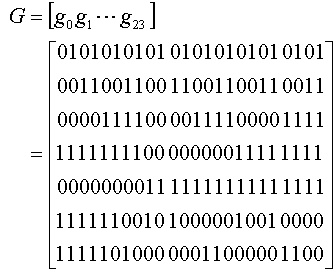
상기 도 10에서 C는 길이 48인 블록 코드를 나타내고, ![]()
![]()
![]()
![]()
![]()
![]()
한편, 상기 파일럿 심벌은 하기 수학식 1과 같은 주파수 영역 시퀀스에 의해 생성된다.
Meanwhile, the pilot symbol is generated by a frequency domain sequence as shown in

상기 수학식 1에서 IDcell은 셀 ID를 나타내며, s는 섹터 ID를 나타내며, k는 서브 캐리어 인덱스를 나타내며, Nused는 상기 OFDM 통신 시스템에서 실제 사용되는 서브 캐리어들의 개수, 즉 DC 성분과 보호 구간 성분을 제외한 서브 캐리어들의 개수를 나타낸다. 또한, 본 발명의 실시예에서는 모든 기지국과 섹터의 파일럿 심벌이 동일한 주파수 오프셋을 사용한다고 가정하기로 한다. 상기 수학식 1에 나타낸 바와 같은 주파수 영역의 시퀀스 ![]()
![]()
또한, 상기 수학식 1에서 ![]()
![]()
![]()
![]()

상기 수학식 2에서 ![]()
![]()
![]()
![]()
![]()
![]()

상기 수학식 3에서 ![]()
![]()
![]()
![]()
![]()
![]()
![]()
![]()
![]()
![]()
![]()
![]()
![]()
![]()

한편, 상기 수학식 4에서 ![]()
![]()
![]()
![]()
![]()
![]()
![]()
![]()

즉, 상기 인터리빙 방식 ![]()
![]()
또한, 상기 수학식 2에서 시퀀스 ![]()
![]()

한편, 상기에서 설명한 바와 같은 파일럿 신호 송수신 방안은 다중 입력 다중 출력(MIMO: Multiple Input Multiple Output) 방식을 사용하고, 섹터의 구분이 필요없는 OFDM 통신 시스템에도 적용 가능하다. 여기서, 상기 섹터의 구분이 필요없기 때문에 상기에서 설명한 파일럿 신호 송수신 방안과는 상이하게 상기 섹터 식별자에 상응하여 상이하게 발생하던 왈쉬 코드를 미리 설정된 왈쉬 코드, 일 예로 all 1 왈쉬 코드로 동일하게 사용한다.여기서, 상기 all 1 왈쉬 코드라 함은 해당 왈쉬 코드를 구성하는 엘리먼트들이 모두 1인 왈쉬 코드를 나타낸다.Meanwhile, the above-described pilot signal transmission / reception scheme uses a multiple input multiple output (MIMO) scheme and is applicable to an OFDM communication system that does not require sector division. In this case, since the division of the sector is not necessary, the Walsh code generated differently from the pilot signal transmission / reception scheme described above corresponding to the sector identifier is used as the pre-set Walsh code, for example, all 1 Walsh code. Here, the all 1 Walsh code refers to a Walsh code in which all elements constituting the Walsh code are 1.
또한, 상기 OFDM 통신 시스템의 송신기, 일 예로 기지국이 Nt개의 송신 안테 나(Tx.ANT)들을 사용할 경우 상기 Nt개의 송신 안테나들 각각을 통해 송신되는 파일럿 심벌들은 하기 수학식 5와 같이 나타낼 수 있다.In addition, when a transmitter of the OFDM communication system, for example, a base station uses N t transmit antennas (Tx.ANT), pilot symbols transmitted through each of the N t transmit antennas may be represented by


상기 수학식 5에서, n은 송신 안테나 ID를 나타내며, k는 서브 캐리어 인덱스를 나타낸다. 또한, 상기 수학식 5에서 ![]()
![]()

상기 수학식 6에서, 시퀀스 R(r)과 T(k)는 상기 송신 안테나들의 개수 Nt와 상기 OFDM 통신 시스템에서 사용하는 IFFT/FFT 연산의 포인트 수 NFFT에 따라 상이하게 정의되며, 따라서 상기 ![]()
![]()
여기서, 상기 송신 안테나들의 개수 Nt와 상기 OFDM 통신 시스템에서 사용하는 IFFT/FFT 연산의 포인트 수 NFFT에 따른 R(r)과, T(k) 및 ![]()
![]()
첫 번째로, 상기 송신 안테나들의 개수가 4개이고, 상기 OFDM 통신 시스템에서 사용하는 IFFT/FFT 연산의 포인트 수가 128일 경우(Nt = 4, NFFT = 128) 상기 R(r)은 하기 수학식 7에 나타낸 바와 같다.First, when the number of transmit antennas is four and the number of points of the IFFT / FFT operation used in the OFDM communication system is 128 (N t = 4, N FFT = 128), the R (r) is As shown in 7.

상기 수학식 7과 같을 경우 블록 코드 생성 행렬 G는 하기 수학식 8과 같이 나타낼 수 있다.
In the case of
상기 수학식 7과 같을 경우 인터리빙 방식은 하기 표 3에 나타낸 바와 같다.In the case of
![]()
![]()
상기 수학식 6의 ![]()
![]()
![]()
![]()


한편 본 발명의 상세한 설명에서는 구체적인 실시예에 관해 설명하였으나, 본 발명의 범위에서 벗어나지 않는 한도내에서 여러 가지 변형이 가능함은 물론이다. 그러므로 본 발명의 범위는 설명된 실시예에 국한되어 정해져서는 안되며 후술하는 특허청구의 범위뿐만 아니라 이 특허청구의 범위와 균등한 것들에 의해 정해져야 한다.
Meanwhile, in the detailed description of the present invention, specific embodiments have been described, but various modifications are possible without departing from the scope of the present invention. Therefore, the scope of the present invention should not be limited to the described embodiments, but should be defined not only by the scope of the following claims, but also by the equivalents of the claims.
상술한 바와 같은 본 발명은, OFDM 통신 시스템에서 블록 코드와 왈쉬 코드를 사용하여 셀 ID 및 섹터 ID를 구분할 수 있도록 하는 파일럿 심벌을 제공함으로써 상기 OFDM 통신 시스템에서 구분 가능한 셀 ID 및 섹터 ID의 개수를 증가시킬 수 있다는 이점을 가진다. 또한, 상기 블록 코드와 왈쉬 코드 뿐만 아니라 PAPR 저감 시퀀스를 사용하여 파일럿 심벌을 생성함으로써 파일럿 심벌의 PAPR 특성을 향상시킨다는 이점을 가진다. 또한, 본 발명은 다중 입력 다중 출력 방식을 사용하고, 섹터의 구분이 필요없는 OFDM 통신 시스템에서 블록 코드와 왈쉬 코드를 사용하여 송신 안테나들 및 셀 ID를 구분할 수 있도록 하는 파일럿 신호 송수신 방안을 제공함으로써 구분 가능한 셀 ID 및 송신 안테나들의 개수를 증가시킨다는 이점을 가진다.As described above, the present invention provides a pilot symbol for distinguishing a cell ID and a sector ID using a block code and a Walsh code in an OFDM communication system, thereby determining the number of distinguishable cell ID and sector ID in the OFDM communication system. It has the advantage of increasing. In addition, by generating a pilot symbol using the block code and the Walsh code as well as the PAPR reduction sequence, the PAPR characteristic of the pilot symbol is improved. In addition, the present invention provides a pilot signal transmission / reception scheme using a multi-input multiple output scheme and distinguishing transmission antennas and cell IDs using block codes and Walsh codes in an OFDM communication system that does not require sector division. There is an advantage in that the number of distinguishable cell IDs and the number of transmit antennas is increased.
Claims (37)


Priority Applications (9)
| Application Number | Priority Date | Filing Date | Title |
|---|---|---|---|
| KR1020040067648A KR100739511B1 (en) | 2004-06-25 | 2004-08-26 | Apparatus and method for transmitting/receiving pilot signal in a communication system using orthogonal frequency division multiplexing scheme |
| US11/165,719 US7586836B2 (en) | 2004-06-25 | 2005-06-24 | Apparatus and method for transmitting/receiving pilot signals in a communication system using an orthogonal frequency division multiplexing scheme |
| CA2563944A CA2563944C (en) | 2004-06-25 | 2005-06-25 | Apparatus and method for transmitting/receiving pilot signals in a communication system using an orthogonal frequency division multiplexing scheme |
| JP2007513079A JP4515501B2 (en) | 2004-06-25 | 2005-06-25 | Apparatus and method for transmitting and receiving pilot signal in communication system using orthogonal frequency division multiple system |
| AU2005257641A AU2005257641B2 (en) | 2004-06-25 | 2005-06-25 | Apparatus and method for transmitting/receiving pilot signals in a communication system using an orthogonal frequency division multiplexing scheme |
| RU2006145908/09A RU2346394C2 (en) | 2004-06-25 | 2005-06-25 | Device and method for control signals transmitting/receiving in orthogonal frequency division communication system |
| CN2005800210117A CN1973467B (en) | 2004-06-25 | 2005-06-25 | Apparatus and method for transmitting/receiving pilot signals in a communication system using an orthogonal frequency division multiplexing scheme |
| PCT/KR2005/001995 WO2006001672A1 (en) | 2004-06-25 | 2005-06-25 | Apparatus and method for transmitting/receiving pilot signals in a communication system using an orthogonal frequency division multiplexing scheme |
| EP05013841.1A EP1610514B1 (en) | 2004-06-25 | 2005-06-27 | Method and apparatus for generating a pilot signal for cell identification in an OFDM system |
Applications Claiming Priority (3)
| Application Number | Priority Date | Filing Date | Title |
|---|---|---|---|
| KR20040048249 | 2004-06-25 | ||
| KR1020040048249 | 2004-06-25 | ||
| KR1020040067648A KR100739511B1 (en) | 2004-06-25 | 2004-08-26 | Apparatus and method for transmitting/receiving pilot signal in a communication system using orthogonal frequency division multiplexing scheme |
Publications (2)
| Publication Number | Publication Date |
|---|---|
| KR20050123022A KR20050123022A (en) | 2005-12-29 |
| KR100739511B1 true KR100739511B1 (en) | 2007-07-13 |
Family
ID=34980054
Family Applications (1)
| Application Number | Title | Priority Date | Filing Date |
|---|---|---|---|
| KR1020040067648A KR100739511B1 (en) | 2004-06-25 | 2004-08-26 | Apparatus and method for transmitting/receiving pilot signal in a communication system using orthogonal frequency division multiplexing scheme |
Country Status (9)
| Country | Link |
|---|---|
| US (1) | US7586836B2 (en) |
| EP (1) | EP1610514B1 (en) |
| JP (1) | JP4515501B2 (en) |
| KR (1) | KR100739511B1 (en) |
| CN (1) | CN1973467B (en) |
| AU (1) | AU2005257641B2 (en) |
| CA (1) | CA2563944C (en) |
| RU (1) | RU2346394C2 (en) |
| WO (1) | WO2006001672A1 (en) |
Families Citing this family (51)
| Publication number | Priority date | Publication date | Assignee | Title |
|---|---|---|---|---|
| US7583586B2 (en) * | 2004-07-02 | 2009-09-01 | Samsung Electronics Co., Ltd | Apparatus and method for transmitting/receiving pilot signal in communication system using OFDM scheme |
| KR100781313B1 (en) * | 2005-06-16 | 2007-12-03 | 엘지전자 주식회사 | Method for transmitting/receiving a OFDM signal and mobile communication terminal using the same |
| US7706328B2 (en) | 2006-01-04 | 2010-04-27 | Qualcomm Incorporated | Methods and apparatus for position location in a wireless network |
| JP4869778B2 (en) * | 2006-01-18 | 2012-02-08 | 株式会社エヌ・ティ・ティ・ドコモ | Transmitting apparatus, receiving apparatus, and communication method |
| US8130857B2 (en) | 2006-01-20 | 2012-03-06 | Qualcomm Incorporated | Method and apparatus for pilot multiplexing in a wireless communication system |
| US8483036B2 (en) * | 2006-02-24 | 2013-07-09 | Lg Electronics Inc. | Method of searching code sequence in mobile communication system |
| WO2007121682A1 (en) * | 2006-04-24 | 2007-11-01 | Shanghai Jiao Tong University | Cell recognition method and apparatus for ofdma cellular system |
| JP4736934B2 (en) * | 2006-04-28 | 2011-07-27 | 日本電気株式会社 | Wireless communication system, pilot sequence allocating apparatus, and pilot sequence allocating method used therefor |
| CN101568167A (en) * | 2006-06-16 | 2009-10-28 | 夏普株式会社 | Mobile station, synchronization detection method, sector identification method and mobile communication system |
| EP2063542B1 (en) * | 2006-06-16 | 2013-06-12 | Sharp Kabushiki Kaisha | Data creation device, data creation method, base station, mobile station, synchronization detection method, sector identification method, information detection method, and mobile communication system |
| JP4952088B2 (en) * | 2006-06-23 | 2012-06-13 | ソニー株式会社 | TRANSMISSION DEVICE, TRANSMISSION METHOD, RECEPTION DEVICE, RECEPTION METHOD, AND TRANSMISSION SYSTEM |
| JP4930006B2 (en) * | 2006-11-22 | 2012-05-09 | 日本電気株式会社 | Mobile communication apparatus, mobile communication system, and power consumption reduction method used therefor |
| US7949926B2 (en) * | 2006-11-30 | 2011-05-24 | Motorola Mobility, Inc. | Method and apparatus for encoding and decoding data |
| US20090028100A1 (en) * | 2007-07-25 | 2009-01-29 | Qualcomm Incorporated | Methods and apparatus for transmitter identification in a wireless network |
| CN101394382B (en) * | 2007-09-19 | 2013-01-16 | 中兴通讯股份有限公司 | Method for reducing pilot sequence collision based on wideband single carrier system |
| CN101911534B (en) | 2007-11-07 | 2014-07-30 | 蔚蓝公司 | Advanced technology frame structure with backward compatibility |
| CN101170393B (en) * | 2007-12-04 | 2011-07-20 | 腾讯科技(深圳)有限公司 | Data transmission method, data transmission device |
| US8165064B2 (en) * | 2008-01-28 | 2012-04-24 | Qualcomm Incorporated | Enhancements to the positioning pilot channel |
| CN101227232B (en) * | 2008-02-01 | 2010-06-09 | 中兴通讯股份有限公司 | Method and apparatus for mapping of downlink pilot frequency initial position |
| CN104158617A (en) | 2008-03-10 | 2014-11-19 | 蔚蓝公司 | Efficient and consistent wireless downlink channel configuration |
| US8412271B2 (en) * | 2008-03-28 | 2013-04-02 | Marvell World Trade Ltd. | Boosted, dedicated reference signal |
| CN102017432B (en) * | 2008-04-23 | 2014-03-12 | 夏普株式会社 | Communication system, transmitter, receiver, and communication method |
| US20090274099A1 (en) * | 2008-05-02 | 2009-11-05 | Qualcomm Incorporated | Methods and apparatus for communicating transmitter information in a communication network |
| CN101304397A (en) * | 2008-06-10 | 2008-11-12 | 上海瀚讯无线技术有限公司 | Pilot frequency design method and transmitting/receiving device for idem frequency interference suppression of OFDM system |
| US8472309B2 (en) | 2008-08-20 | 2013-06-25 | Qualcomm Incorporated | Using CDMA to send uplink signals in WLANs |
| CN101772148B (en) * | 2009-01-05 | 2015-05-20 | 中兴通讯股份有限公司 | Auxiliary synchronizing channel configuring method and device, and subcarrier mapping method and device |
| KR101593702B1 (en) * | 2009-03-22 | 2016-02-15 | 엘지전자 주식회사 | Method and apparatus for reference signal in wireless communication system |
| US8385443B2 (en) * | 2009-07-17 | 2013-02-26 | Qualcomm Incorporated | Constructing very high throughput long training field sequences |
| US8917784B2 (en) | 2009-07-17 | 2014-12-23 | Qualcomm Incorporated | Method and apparatus for constructing very high throughput long training field sequences |
| KR101653007B1 (en) * | 2009-08-25 | 2016-09-01 | 한국전자통신연구원 | Frame generation/tansmission method and apparatus for wireless communication, synchronization estimation method for wireless communication |
| CN102026219B (en) * | 2009-09-22 | 2013-06-12 | 中兴通讯股份有限公司 | Method and corresponding device for generating and transmitting wireless channel measurement reference signal |
| WO2011046277A1 (en) * | 2009-10-12 | 2011-04-21 | Lg Electronics Inc. | Method for allocating preamble sequence subblock for supporting irregular system bandwidth in wireless communication system and an apparatus therefor |
| KR101771257B1 (en) * | 2010-12-03 | 2017-08-25 | 엘지전자 주식회사 | Method and apparatus for cooperative transmisstion in multi node system |
| CN102255857B (en) * | 2011-08-22 | 2013-07-24 | 宁波大学 | Multimedia broadcast single-frequency network anti-fading mobile signal framing modulation method |
| CN102255860B (en) * | 2011-08-22 | 2013-09-25 | 宁波大学 | Anti-interference digital mobile broadcasting signal transmission method |
| CN102255856B (en) * | 2011-08-22 | 2013-07-03 | 宁波大学 | Method for transmitting radio digital broadcasting signal |
| CN102255863B (en) * | 2011-08-22 | 2013-07-24 | 宁波大学 | Anti-noise digital mobile broadcast signal transmitting method |
| CN102255854B (en) * | 2011-08-22 | 2013-07-03 | 宁波大学 | Anti-interference method for transmitting wireless digital broadcast signal |
| CN102255699B (en) * | 2011-08-22 | 2013-06-26 | 宁波大学 | Method for framing and modulating anti-fading wireless multimedia broadcast signals |
| CN102238131B (en) * | 2011-08-22 | 2013-06-12 | 宁波大学 | Anti-interference radio signal framing modulation method for multimedia broadcast single-frequency network |
| US9419830B2 (en) | 2012-03-28 | 2016-08-16 | Intel Corporation | Device, system and method of communicating a wireless communication orthogonal-frequency-division-multiplexing signal |
| JP5942561B2 (en) * | 2012-04-18 | 2016-06-29 | アイコム株式会社 | COMMUNICATION DEVICE AND COMMUNICATION METHOD |
| US9649165B2 (en) * | 2012-07-16 | 2017-05-16 | Cardiac Innovation, Llc | Medical device identifier |
| WO2015168628A1 (en) * | 2014-05-02 | 2015-11-05 | Huawei Technologies Co., Ltd. | System and method for grassmannian signaling in a broadband network |
| WO2017070175A1 (en) * | 2015-10-23 | 2017-04-27 | The Hillman Group, Inc. | Wall mounted storage system and related components and methods |
| CN107689855B (en) * | 2016-08-05 | 2022-07-29 | 大唐移动通信设备有限公司 | Signal transmitting and receiving method and equipment |
| CN107920356A (en) * | 2016-10-08 | 2018-04-17 | 中兴通讯股份有限公司 | Interference source cell positioning method and device and corresponding base station |
| CN109587659B (en) | 2017-09-29 | 2022-05-27 | 中兴通讯股份有限公司 | Signal sending method and system |
| US11233685B2 (en) * | 2018-01-12 | 2022-01-25 | Qualcomm Incorporated | Orthogonal cover code (OCC) sequences design for uplink transmissions |
| WO2020226386A1 (en) * | 2019-05-03 | 2020-11-12 | 엘지전자 주식회사 | Method for transmitting sidelink signal in wireless communication system |
| CN114362839B (en) * | 2021-12-07 | 2024-05-03 | 芯象半导体科技(北京)有限公司 | Signal detection method and device based on HPLC dual-mode wireless system and electronic equipment |
Citations (7)
| Publication number | Priority date | Publication date | Assignee | Title |
|---|---|---|---|---|
| WO1997013339A1 (en) * | 1995-10-04 | 1997-04-10 | Philips Electronics N.V. | Dab receiver, apparatus and method for a format conversion of a dab data sequence |
| WO1998000952A1 (en) * | 1996-07-02 | 1998-01-08 | Sony Corporation | Information transmitter and information transmitting method |
| KR20000042359A (en) * | 1998-12-24 | 2000-07-15 | 강상훈 | Transmitter for reverse directional link in communication system |
| JP2001197025A (en) * | 2000-01-17 | 2001-07-19 | Matsushita Electric Ind Co Ltd | Method and system for digital broadcast transmission and reception |
| KR20020034977A (en) * | 2000-11-03 | 2002-05-09 | 루센트 테크놀러지스 인크 | Apparatus and method for use in the multicast of traffic data in wireless multiple access communications systems |
| US6567374B1 (en) | 1998-02-18 | 2003-05-20 | Sony International (Europe) Gmbh | Data and pilot mapping in an OFDM system |
| US6611551B1 (en) | 1999-01-21 | 2003-08-26 | Cisco Technology, Inc. | OFDM channel identification |
Family Cites Families (26)
| Publication number | Priority date | Publication date | Assignee | Title |
|---|---|---|---|---|
| US5757767A (en) * | 1995-04-18 | 1998-05-26 | Qualcomm Incorporated | Method and apparatus for joint transmission of multiple data signals in spread spectrum communication systems |
| US5577025A (en) * | 1995-06-30 | 1996-11-19 | Qualcomm Incorporated | Signal acquisition in a multi-user communication system using multiple walsh channels |
| DE19635813A1 (en) * | 1996-09-04 | 1998-03-05 | Johannes Prof Dr Ing Huber | Process for reducing the peak value factor in digital transmission processes |
| JP3576787B2 (en) * | 1998-01-22 | 2004-10-13 | 株式会社東芝 | OFDM signal transmitting / receiving method, OFDM signal transmitting / receiving apparatus, OFDM signal transmitting method, and OFDM signal transmitting apparatus |
| US6711120B1 (en) * | 1999-03-11 | 2004-03-23 | Flarion Technologies, Inc. | Orthogonal frequency division multiplexing based spread spectrum multiple access |
| JP4313925B2 (en) * | 2000-03-17 | 2009-08-12 | 富士通株式会社 | Multi-carrier direct spread transmitter / receiver system, multi-carrier direct spread transmitter / receiver, multi-carrier direct spread transmitter and multi-carrier direct spread receiver |
| US6928084B2 (en) * | 2000-03-28 | 2005-08-09 | At & T Corp. | OFDM communication system and method having a reduced peak-to-average power ratio |
| DE60102117T2 (en) * | 2000-08-02 | 2004-09-09 | Lucent Technologies Inc. | Method of reducing the peak to medium power ratio in a wireless communication system |
| RU2186465C2 (en) | 2000-08-14 | 2002-07-27 | Гармонов Александр Васильевич | Method for organizing radio interface and base station of cellular communication system |
| RU2208911C2 (en) | 2001-05-14 | 2003-07-20 | Гармонов Александр Васильевич | Method of diversified signal transmission and device for its realization |
| JP2003087218A (en) * | 2001-06-29 | 2003-03-20 | Matsushita Electric Ind Co Ltd | Multicarrier sending device, multicarrier receiving device and method for multicarrier radio communication |
| JP2003032220A (en) * | 2001-07-17 | 2003-01-31 | Matsushita Electric Ind Co Ltd | Transmitter, receiver, and radio communication method |
| CN100566222C (en) * | 2001-09-28 | 2009-12-02 | 富士通株式会社 | Channel estimating apparatus and method |
| US7548506B2 (en) * | 2001-10-17 | 2009-06-16 | Nortel Networks Limited | System access and synchronization methods for MIMO OFDM communications systems and physical layer packet and preamble design |
| US20030081538A1 (en) * | 2001-10-18 | 2003-05-01 | Walton Jay R. | Multiple-access hybrid OFDM-CDMA system |
| US6854082B1 (en) * | 2001-11-27 | 2005-02-08 | Lsi Logic Corporation | Unequal error protection Reed-Muller code generator and decoder |
| JP3694479B2 (en) * | 2001-12-07 | 2005-09-14 | 松下電器産業株式会社 | Multi-carrier transceiver apparatus, multi-carrier wireless communication method, and multi-carrier wireless communication program |
| JP3860762B2 (en) * | 2002-02-14 | 2006-12-20 | 株式会社エヌ・ティ・ティ・ドコモ | Mobile communication system, channel synchronization establishment method, and mobile station |
| WO2004021616A1 (en) * | 2002-08-28 | 2004-03-11 | Fujitsu Limited | Transmission/reception apparatus and transmission/reception method |
| JP4291669B2 (en) * | 2002-11-01 | 2009-07-08 | パナソニック株式会社 | Multi-carrier communication apparatus and multi-carrier communication method |
| KR100479864B1 (en) * | 2002-11-26 | 2005-03-31 | 학교법인 중앙대학교 | Method and apparatus embodying and synchronizing downlink signal in mobile communication system and method for searching cell using the same |
| KR100905572B1 (en) * | 2002-12-03 | 2009-07-02 | 삼성전자주식회사 | Apparatus and method for generating preamble sequence in a communication system using orthogonal frequency division multiplexing scheme |
| US7280467B2 (en) * | 2003-01-07 | 2007-10-09 | Qualcomm Incorporated | Pilot transmission schemes for wireless multi-carrier communication systems |
| RU2333606C2 (en) | 2004-03-05 | 2008-09-10 | Самсунг Электроникс Ко., Лтд. | Device and method of transmitting/receiving pilot signal in communication system, using ofdm scheme |
| US7567639B2 (en) * | 2004-04-28 | 2009-07-28 | Samsung Electronics Co., Ltd | Method and apparatus for generating preamble sequence for adaptive antenna system in orthogonal frequency division multiple access communication system |
| US7660362B2 (en) * | 2004-06-18 | 2010-02-09 | Broadcom Corporation | Wireless local area network system using space-time block coding (STBC) having backward compatibility with prior standards |
-
2004
- 2004-08-26 KR KR1020040067648A patent/KR100739511B1/en not_active IP Right Cessation
-
2005
- 2005-06-24 US US11/165,719 patent/US7586836B2/en active Active
- 2005-06-25 CA CA2563944A patent/CA2563944C/en active Active
- 2005-06-25 JP JP2007513079A patent/JP4515501B2/en not_active Expired - Fee Related
- 2005-06-25 RU RU2006145908/09A patent/RU2346394C2/en active
- 2005-06-25 CN CN2005800210117A patent/CN1973467B/en active Active
- 2005-06-25 AU AU2005257641A patent/AU2005257641B2/en not_active Ceased
- 2005-06-25 WO PCT/KR2005/001995 patent/WO2006001672A1/en active Application Filing
- 2005-06-27 EP EP05013841.1A patent/EP1610514B1/en not_active Expired - Fee Related
Patent Citations (7)
| Publication number | Priority date | Publication date | Assignee | Title |
|---|---|---|---|---|
| WO1997013339A1 (en) * | 1995-10-04 | 1997-04-10 | Philips Electronics N.V. | Dab receiver, apparatus and method for a format conversion of a dab data sequence |
| WO1998000952A1 (en) * | 1996-07-02 | 1998-01-08 | Sony Corporation | Information transmitter and information transmitting method |
| US6567374B1 (en) | 1998-02-18 | 2003-05-20 | Sony International (Europe) Gmbh | Data and pilot mapping in an OFDM system |
| KR20000042359A (en) * | 1998-12-24 | 2000-07-15 | 강상훈 | Transmitter for reverse directional link in communication system |
| US6611551B1 (en) | 1999-01-21 | 2003-08-26 | Cisco Technology, Inc. | OFDM channel identification |
| JP2001197025A (en) * | 2000-01-17 | 2001-07-19 | Matsushita Electric Ind Co Ltd | Method and system for digital broadcast transmission and reception |
| KR20020034977A (en) * | 2000-11-03 | 2002-05-09 | 루센트 테크놀러지스 인크 | Apparatus and method for use in the multicast of traffic data in wireless multiple access communications systems |
Non-Patent Citations (2)
| Title |
|---|
| 한국공개특허공보 10-2000-0042359 |
| 한국공개특허공보 특2002-0034977 |
Also Published As
| Publication number | Publication date |
|---|---|
| WO2006001672A1 (en) | 2006-01-05 |
| CN1973467B (en) | 2012-01-18 |
| US20060018251A1 (en) | 2006-01-26 |
| AU2005257641B2 (en) | 2009-02-05 |
| US7586836B2 (en) | 2009-09-08 |
| JP4515501B2 (en) | 2010-08-04 |
| CA2563944C (en) | 2012-07-31 |
| CN1973467A (en) | 2007-05-30 |
| EP1610514B1 (en) | 2020-01-08 |
| EP1610514A1 (en) | 2005-12-28 |
| AU2005257641A1 (en) | 2006-01-05 |
| RU2346394C2 (en) | 2009-02-10 |
| KR20050123022A (en) | 2005-12-29 |
| JP2007536875A (en) | 2007-12-13 |
| CA2563944A1 (en) | 2006-01-05 |
| RU2006145908A (en) | 2008-06-27 |
Similar Documents
| Publication | Publication Date | Title |
|---|---|---|
| KR100739511B1 (en) | Apparatus and method for transmitting/receiving pilot signal in a communication system using orthogonal frequency division multiplexing scheme | |
| JP4417414B2 (en) | Pilot signal transmitting / receiving apparatus and method in communication system using orthogonal frequency division multiplexing | |
| KR100957415B1 (en) | Apparatus for transmitting/receiving a pilot signal for distinguish a base station in a communication using orthogonal frequency division multiplexing scheme and method thereof | |
| KR100933115B1 (en) | Apparatus and method for reducing peak to average power ratio in a orthogonal frequency division multiplexing communication system | |
| US7269782B2 (en) | Orthogonal frequency division multiplexing/modulation communication system for improving ability of data transmission and method thereof | |
| US7583586B2 (en) | Apparatus and method for transmitting/receiving pilot signal in communication system using OFDM scheme | |
| KR100688118B1 (en) | Apparatus and method for reducing peak to average power ratio in orthogonal frequency division multiplexing communication system | |
| US20040257979A1 (en) | Apparatus and method for tranmitting and receiving a pilot pattern for identification of a base station in an OFDM communication system | |
| US20040257981A1 (en) | Apparatus and method for transmitting and receiving pilot patterns for identifying base stations in an OFDM communication system | |
| KR101051322B1 (en) | Apparatus and method for transmitting and receiving pilot signals in a communication system using orthogonal frequency division multiplexing | |
| KR100918736B1 (en) | Apparatus and method for transmitting/receiving pilot signal in a communication system | |
| KR20050082968A (en) | Apparatus and method for transmitting/receiving channel quality information in a communication system using orthogonal frequency division multiplexing scheme | |
| KR20050119592A (en) | Apparatus and method for channel estimation in a mobile communication system using an frequency hopping - orthogonal frequency division multipl access scheme |
Legal Events
| Date | Code | Title | Description |
|---|---|---|---|
| A201 | Request for examination | ||
| E902 | Notification of reason for refusal | ||
| E701 | Decision to grant or registration of patent right | ||
| GRNT | Written decision to grant | ||
| FPAY | Annual fee payment |
Payment date: 20130627 Year of fee payment: 7 |
|
| FPAY | Annual fee payment |
Payment date: 20140627 Year of fee payment: 8 |
|
| FPAY | Annual fee payment |
Payment date: 20150629 Year of fee payment: 9 |
|
| LAPS | Lapse due to unpaid annual fee |