KR100605860B1 - Apparatus and method for transmitting in wireless telecommunication system using 4 transmit antennas - Google Patents
Apparatus and method for transmitting in wireless telecommunication system using 4 transmit antennas Download PDFInfo
- Publication number
- KR100605860B1 KR100605860B1 KR1020030001454A KR20030001454A KR100605860B1 KR 100605860 B1 KR100605860 B1 KR 100605860B1 KR 1020030001454 A KR1020030001454 A KR 1020030001454A KR 20030001454 A KR20030001454 A KR 20030001454A KR 100605860 B1 KR100605860 B1 KR 100605860B1
- Authority
- KR
- South Korea
- Prior art keywords
- symbols
- transmitting
- phase
- coding matrix
- transmitted
- Prior art date
Links
Images


Classifications
-
- H—ELECTRICITY
- H04—ELECTRIC COMMUNICATION TECHNIQUE
- H04B—TRANSMISSION
- H04B7/00—Radio transmission systems, i.e. using radiation field
- H04B7/02—Diversity systems; Multi-antenna system, i.e. transmission or reception using multiple antennas
-
- H—ELECTRICITY
- H04—ELECTRIC COMMUNICATION TECHNIQUE
- H04L—TRANSMISSION OF DIGITAL INFORMATION, e.g. TELEGRAPHIC COMMUNICATION
- H04L1/00—Arrangements for detecting or preventing errors in the information received
- H04L1/02—Arrangements for detecting or preventing errors in the information received by diversity reception
- H04L1/06—Arrangements for detecting or preventing errors in the information received by diversity reception using space diversity
- H04L1/0618—Space-time coding
- H04L1/0637—Properties of the code
- H04L1/0662—Limited orthogonality systems
Abstract
본 발명은 무선통신 시스템에서 페이딩에 의한 열화에 대응하기 위해 송신 안테나 다이버시티를 사용하는 장치에 관한 것으로서, 4개의 송신 안테나들을 통해 전송되는 4개의 심볼들 중 적어도 2개를 소정의 위상값만큼 위상 회전시킨다. 본 발명의 일 실시예에 따른 부호화기는 입력되는 4개의 심볼들이 각 안테나와 각 시간구간에서 한번씩만 전송되도록 각각 4개의 심볼들을 포함하는 4개의 조합들로 구성하고 상기 조합들을 4개의 시간구간들 동안 4개의 송신 안테나들로 전달하며, 여기서 상기 입력되는 4개의 심볼들 중 선택된 적어도 2개의 심볼들을 상기 송신 안테나들로 전송하기 이전에 각각 소정의 위상값들만큼 회전시킨다. 이러한 본 발명은 최대의 다이버시티 차수를 얻으며 송신 지연시간을 감소시켜 고속 페이딩에 대항한다.The present invention relates to an apparatus using transmit antenna diversity to counteract fading degradation in a wireless communication system, wherein at least two of four symbols transmitted through four transmit antennas are phased by a predetermined phase value. Rotate The encoder according to an embodiment of the present invention comprises four combinations each of which includes four symbols such that four input symbols are transmitted only once in each antenna and each time period, and the combinations are used for four time periods. And transmits to four transmit antennas, wherein at least two selected ones of the four input symbols are rotated by predetermined phase values before being transmitted to the transmit antennas. This invention achieves maximum diversity order and reduces transmission delay time to counter fast fading.
TRANSMIT DIVERSITY, 4 ANTENNAS, SPACE TIME BLOCK CODE, MAXIMUM LIKELIHOOD DECODERTRANSMIT DIVERSITY, 4 ANTENNAS, SPACE TIME BLOCK CODE, MAXIMUM LIKELIHOOD DECODER
Description
도 1은 종래 기술에 따른 공간-시간 블럭부호를 사용하는 송신기의 구성을 나타낸 블럭도.1 is a block diagram showing a configuration of a transmitter using a space-time block code according to the prior art.
도 2는 상기 도 1의 송신기로부터 송신된 신호를 수신하는 수신기의 구성을 나타낸 블럭 구성도.2 is a block diagram showing the configuration of a receiver for receiving a signal transmitted from the transmitter of FIG.
도 3은 본 발명의 일 실시예에 따른 공간-시간 블럭부호를 사용하는 송신기의 구성을 나타낸 블럭도.3 is a block diagram showing a configuration of a transmitter using a space-time block code according to an embodiment of the present invention.
도 4는 상기 도 3의 송신기로부터 송신된 신호를 수신하는 수신기의 구성을 나타낸 블럭도.4 is a block diagram showing a configuration of a receiver for receiving a signal transmitted from the transmitter of FIG.
도 5는 본 발명의 일 실시예에서 QPSK의 사용시 2개의 위상값들에 대한 최소 부호화 이득의 변화를 나타낸 시뮬레이션 결과.5 is a simulation result showing a change in the minimum coding gain for two phase values when using QPSK in one embodiment of the present invention.
도 6은 45도만큼 위상 회전된 QPSK 성상도.6 is a QPSK constellation phase rotated by 45 degrees.
도 7은 본 발명의 일 실시예에 따른 블럭 부호화 기술을 종래의 다른 기술들과 신호대 잡음비(SNR)에 대한 비트 오류율(BER)의 관점에서 비교한 도면.7 is a block coding technique according to an embodiment of the present invention compared with other conventional techniques in terms of bit error rate (BER) for signal-to-noise ratio (SNR).
본 발명은 무선통신 시스템에 관한 것으로서, 특히 페이딩(Fading) 열화(Degradation)에 대응하기 위해 4개의 송신 안테나들을 이용한 송신 안테나 다이버시티를 사용하는 송신 장치 및 방법에 관한 것이다.BACKGROUND OF THE INVENTION 1. Field of the Invention The present invention relates to wireless communication systems, and more particularly, to a transmission apparatus and a method using transmission antenna diversity using four transmission antennas to counter fading degradation.
무선통신 시스템에서 다중경로 페이딩을 완화시키기 위한 효과적인 기술 중의 하나는 시간과 주파수 다이버시티(time and frequency diversity)이다. 안테나 다이버시티를 위한 알려진 기술 중의 Vahid Tarokh 등에 의해 제안된 공간-시간 블럭부호(Space time block code)는 S.M. Alamouti가 제안한 송신 안테나 다이버시티 기술을 2개 이상의 안테나들을 사용할 수 있도록 확장한 것이다. Tarokh에 의한 제안은 "Space time block coding from orthogonal design," IEEE Trans. on Info., Theory, Vol. 45, pp. 1456-1467, July 1999에 공개되어 있으며, Alamouti에 의한 제안은 "A simple transmitter diversity scheme for wireless communications," IEEE Journal on Selected Area in Communications, Vol. 16, pp. 1451-1458, Oct. 1998에 공개되어 있다.One effective technique for mitigating multipath fading in wireless communication systems is time and frequency diversity. The space time block code proposed by Vahid Tarokh et al. Among known techniques for antenna diversity is S.M. Alamouti's proposed transmit antenna diversity technology extends to more than two antennas. The proposal by Tarokh is "Space time block coding from orthogonal design," IEEE Trans. on Info., Theory, Vol. 45, pp. 1456-1467, July 1999, and a proposal by Alamouti for example "A simple transmitter diversity scheme for wireless communications," IEEE Journal on Selected Area in Communications, Vol. 16, pp. 1451-1458, Oct. Published in 1998.
도 1은 종래 기술에 따른 공간-시간 블럭부호를 사용하는 송신기의 구성을 나타낸 블럭도이다. 이는 Tarokh에 의해 제안된 것으로서, 도시한 바와 같이 직/병렬 변환기(Serial to Parallel Converter: S/P Converter)(110)와 부호화기(Encoder)(120)로 구성되어 있다. 여기서는 4개의 송신 안테나들(130,132,134,136)을 사용하는 구조를 도시하였다.1 is a block diagram showing the configuration of a transmitter using a space-time block code according to the prior art. As proposed by Tarokh, it is composed of a serial to parallel converter (S / P converter) 110 and an
상기 도 1을 참조하면, 상기 직/병렬 변환기(110)는 입력되는 심볼들을 4개씩 묶어 상기 부호화기(120)로 제공한다. 상기 부호화기(120)는 상기 4개의 심볼들을 가지고 8개의 조합들을 구성하여 8개의 시간구간들 동안 각 심볼 열들을 상기 4개의 송신 안테나들(130,132,134,136)로 전달한다. 상기 8개의 조합들은 하기의 <수학식 1>와 같은 8x4의 부호화 행렬로 나타낼 수 있다.Referring to FIG. 1, the serial /

여기서 G4는 4개의 송신 안테나들로 전송되는 심볼들의 부호화 행렬을 나타내고, s1,s2,s3,s4는 전송하고자 하는 4개의 입력 심볼들을 나타낸다.Here, G 4 represents an encoding matrix of symbols transmitted through four transmit antennas, and s 1 , s 2 , s 3 , and s 4 represent four input symbols to be transmitted.
상기와 같이 상기 부호화기(120)는 입력되는 4개의 심볼들에 반전(negative)과 공액(conjugate)을 적용하여 8개의 시간구간동안 4개의 안테나들(130,132,134,136)로 출력한다. 여기서 각각의 안테나들로 출력되는 심볼 열들은 상호간에 직교성을 가지게 된다.As described above, the
보다 구체적으로 설명하면, 제1 시간구간에서는 첫 번째 열의 4개의 심볼들 s1,s2,s3,s4가 상기 4개의 안테나들(130,132,134,136)로 각각 전달되며, 마찬가지로 마지막 시간구간에서는 마지막 열의 4개의 심볼들 -s4 *,-s3 *,s2 *,s1 *가 상기 4개의 안테나들(130,132,134,136)로 각각 전달된다. 즉, 상기 부호화기(120)는 m번째 안테나로 상기 부호화 행렬의 m번째 열의 심볼들을 순서대로 전달한다. More specifically, in the first time interval, four symbols s 1 , s 2 , s 3 , and s 4 in the first column are transmitted to the four
도 2는 상기 도 1의 송신기로부터 송신된 신호를 수신하는 수신기의 구성을 나타낸 블럭도로서, 도시한 바와 같이 복수의 수신 안테나들(140,145)과 채널 추정기(Channel Estimator)(150)와 다중채널 심볼 배열기(Multiple Channel Symbol Arranger)(160)와 검출기(Detector)(170)로 구성된다.FIG. 2 is a block diagram illustrating a configuration of a receiver for receiving a signal transmitted from the transmitter of FIG. 1, and as illustrated, a plurality of receiving
상기 도 2를 참조하면, 상기 채널 추정기(150)는 송신 안테나들(130 내지 136)로부터 수신 안테나들(140 내지 145)로의 채널 이득들을 나타내는 채널 계수들(channel coefficients)을 추정하며, 상기 다중채널 심볼 배열기(160)는 상기 수신 안테나들(140,142)에 의해 수신된 심볼들을 수집하여 상기 검출기(170)로 제공한다. 그러면 상기 검출기(170)는 상기 수신 심볼들에 상기 채널 계수들을 곱하여 구한 추정(hypotheses) 심볼들을 가지고 가능한 모든 심볼들에 대한 결정 통계량(decision statistic)을 계산한 뒤 임계값 검출(threshold detection)에 의해 원하는 심볼들을 검출한다.Referring to FIG. 2, the
Alamouti의 공간-시간 블럭부호 기술은 2개의 송신 안테나들을 통해 복소 심볼들(complex symbols)을 전송하더라도 전송율(rate)을 손실하지 않고 송신 안테나들의 개수와 동일한, 즉 최대의 다이버시티 차수(diversity order)를 얻는다. 이를 확장하여 Tarokh에 의해 제안된 상기 도 1과 도 2의 장치들은 상호간에 직교적인(orthogonal) 열들을 가지는 행렬 형태의 공간-시간 블럭부호를 사용하여 최대 다이버시티 차수를 얻는다. 그러나 상기 장치들은 4개의 복소 심볼들을 8개의 시간구간(time interval) 동안 전송하기 때문에 1/2의 전송율이 손실된다. 또한 한 블럭(4개의 심볼들)을 완전히 전송하는데 8개의 시간구간이 소요되기 때문에 고속 페이딩의 경우 블럭 내에서 채널환경의 변화에 의해 수신 성능이 나빠진다.Alamouti's space-time block coding technology transmits complex symbols through two transmit antennas, but does not lose the rate but equals the number of transmit antennas, i.e. the maximum diversity order. Get Extending this, the devices of Figs. 1 and 2 proposed by Tarokh obtain a maximum diversity order using matrix-like space-time block codes with orthogonal columns. However, since the devices transmit four complex symbols for eight time intervals, a half rate is lost. In addition, since it takes eight time intervals to completely transmit one block (four symbols), in case of fast fading, reception performance is deteriorated due to a change in channel environment within the block.
이상과 같이 4개의 송신 안테나들을 사용하여 복소 심볼들을 전송하는 경우, N개의 심볼들을 송신하기 위해 2N개의 시간구간이 걸리므로 전송율의 손실이 발생하여 지연시간(latency)이 길어지고 전송율이 저하되었다는 문제점이 있었다.As described above, in case of transmitting complex symbols using four transmission antennas, since 2N time intervals are required to transmit N symbols, a loss of transmission rate occurs, resulting in a long delay and a low transmission rate. There was this.
따라서 상기한 바와 같이 동작되는 종래 기술의 문제점을 해결하기 위하여 창안된 본 발명은 4개의 송신 안테나들을 사용하는 무선통신 시스템에서 전송율의 손실없이 최대의 다이버시티 차수와 최대의 전송율을 얻는 송신 장치 및 방법을 제공한다.Accordingly, the present invention, which is designed to solve the problems of the prior art operating as described above, is a transmission apparatus and method for obtaining a maximum diversity order and a maximum transmission rate without loss of transmission rate in a wireless communication system using four transmission antennas. To provide.
또한 본 발명은 4개의 송신 안테나들을 사용하는 무선통신 시스템에서 전송율의 손실 없이 전송 지연시간을 최소화하는 송신 장치 및 방법을 제공한다.
전술한 목적을 달성하기 위해 본 발명에서는, 복소 심볼들을 전송하는 무선통신 시스템에서, 4개의 송신 안테나들과, 전송하고자 하는 4개의 심볼들을 입력으로 하고, 상기 4개의 심볼들 중 두 개의 심볼들을 상기 두 개의 심볼들 각각에 대해 미리 결정된 위상 값들로 승산하여 위상 회전된 심볼들을 출력하는 위상 회전기 및 각 시간 구간에서 상기 위상 회전된 두 개의 심볼들이 포함된 4개의 심볼들이 상기 4개의 송신 안테나들을 통해 전송되도록 하는 4x4 부호화 행렬들 중 하나를 선택하고, 상기 선택된 4x4 부호화 행렬을 구성하는 원소들 중 일부 원소들에 대해 반전 또는 공액 또는 반전과 공액을 취하여 새로운 4x4 부호화 행렬을 생성하며, 각 시간 구간에서 상기 생성한 4x4 부호화 행렬을 구성하는 행들을 순차적으로 선택한 후 상기 선택된 열의 복소 심볼들을 상기 송신 안테나들로 전달하는 부호화기를 포함하는 송신장치를 제안한다.The present invention also provides a transmission apparatus and method for minimizing transmission delay time without loss of transmission rate in a wireless communication system using four transmission antennas.
In order to achieve the above object, in the present invention, in a wireless communication system for transmitting complex symbols, four transmission antennas and four symbols to be transmitted are input, and two symbols among the four symbols are inputted. A phase rotator multiplying predetermined phase values for each of the two symbols to output phase rotated symbols, and four symbols including the two phase rotated symbols in each time interval are transmitted through the four transmit antennas. Select one of the 4x4 coding matrices, and inverse or conjugate or inverse and conjugate with respect to some of the elements constituting the selected 4x4 coding matrix to generate a new 4x4 coding matrix; After sequentially selecting the rows constituting the generated 4x4 coding matrix, the selected columns It offers a transmission device including an encoder for transmitting the symbols to the transmit antennas.
전술한 목적을 달성하기 위해 본 발명에서는, 4개의 송신 안테나들을 통해 복소 심볼들을 전송하는 무선통신 시스템에서, 전송하고자 하는 4개의 심볼들을 입력으로 하고, 상기 4개의 심볼들 중 두 개의 심볼들을 상기 두 개의 심볼들 각각에 대해 미리 결정된 위상 값들로 승산하여 위상 회전된 심볼들을 출력하는 과정과, 각 시간 구간에서 상기 위상 회전된 두 개의 심볼들이 포함된 4개의 심볼들이 상기 4개의 송신 안테나들을 통해 전송되도록 하는 4x4 부호화 행렬들 중 하나를 선택하는 과정과, 상기 선택된 4x4 부호화 행렬을 구성하는 원소들 중 일부 원소들에 대해 반전 또는 공액 또는 반전과 공액을 취하여 새로운 4x4 부호화 행렬을 생성하는 과정 및 각 시간 구간에서 상기 생성한 4x4 부호화 행렬을 구성하는 행들을 순차적으로 선택한 후 상기 선택된 열의 복소 심볼들을 상기 송신 안테나들로 전달하는 과정을 포함하는 송신방법을 제안한다.In order to achieve the above object, in the present invention, in a wireless communication system for transmitting complex symbols through four transmit antennas, four symbols to be transmitted are input, and two of the four symbols are the two symbols. Outputting phase rotated symbols by multiplying predetermined phase values for each of the plurality of symbols, and transmitting four symbols including the two phase rotated symbols in each time interval to be transmitted through the four transmit antennas. Selecting one of the 4x4 coding matrices, generating a new 4x4 coding matrix by inverting or conjugating or inverting and conjugating some of the elements constituting the selected 4x4 coding matrix and each time interval Sequentially selects rows constituting the generated 4x4 coding matrix from The complex symbols of the column, we propose a transmission method comprising the step of forwarding to the transmission antennas.
삭제delete
삭제delete
삭제delete
삭제delete
삭제delete
삭제delete
삭제delete
삭제delete
하기에서 본 발명을 설명함에 있어 관련된 공지 기능 또는 구성에 대한 구체 적인 설명이 본 발명의 요지를 불필요하게 흐릴 수 있다고 판단되는 경우에는 그 상세한 설명을 생략할 것이다. 그리고 후술되는 용어들은 본 발명에서의 기능을 고려하여 정의된 용어들로서 이는 사용자, 운용자의 의도 또는 관례 등에 따라 달라질 수 있다. 그러므로 그 정의는 본 명세서 전반에 걸친 내용을 토대로 내려져야 할 것이다.In the following description of the present invention, detailed descriptions of well-known functions or configurations will be omitted when it is determined that the detailed description may unnecessarily obscure the subject matter of the present invention. Terms to be described later are terms defined in consideration of functions in the present invention, and may be changed according to intentions or customs of users or operators. Therefore, the definition should be made based on the contents throughout the specification.
후술되는 본 발명에서는 최대 다이버시티 차수와 최대 전송율을 얻기 위해 전송 복소 심볼들(complex symbols)의 일부를 위상 회전(rotate)시키고 디코딩 설계를 간단하게 하기 위해 부분적인 직교 구조를 도입한다. 하기에서는 전송 복소 심볼들 중 선택된 2개의 송신 심볼들을 위상 회전시키는 구성 및 동작에 대해 설명할 것이지만 본 발명의 기능을 달성하기 위해서는 2개 이상 임의 개수의 송신 심볼들을 회전시키는 것이 가능함은 물론이다.The present invention described below introduces a partial orthogonal structure to phase rotate some of the complex symbols and to simplify the decoding design to obtain the maximum diversity order and maximum rate. In the following description, a configuration and operation of phase-rotating two selected transmission symbols among transmission complex symbols will be described. However, it is a matter of course that two or more arbitrary numbers of transmission symbols can be rotated in order to achieve the function of the present invention.
본 발명에서는 4개의 입력 심볼들을 4개의 송신 안테나들을 통해 4개의 시간구간 동안 전송하는데, 이를 부호화 행렬로 표현하면 하기의 <수학식 2>와 같다.In the present invention, four input symbols are transmitted for four time periods through four transmit antennas, which are represented by

알려진 바와 같이 최대 우도 (ML; Maximum Likelihood) 디코딩을 사용하는 수신기에서는 송신 안테나로부터 수신 안테나로의 채널 이득을 사용하여 가능한 모든 심볼에 대하여 수신 신호와의 메트릭 값을 구하고, 상기 구해진 메트릭 값을 최소로 하는 심볼을 검출하는 방식을 사용한다.As is known, a receiver using Maximum Likelihood (ML) decoding uses the channel gain from a transmitting antenna to a receiving antenna to obtain a metric value with the received signal for all possible symbols, and to minimize the metric value obtained. A method of detecting a symbol is used.
그러면 상기 <수학식 2>와 같은 심볼들을 수신하는 수신기에서 i번째 송신 안테나로부터 한 수신 안테나로의 채널 이득을 hi라 표현할 때, 임의의 시간구간 t에서 생성된 심볼 조합(symbol combination) ct에 대응하는 메트릭 값은 하기의 <수학식 3>과 같이 표현된다.Then, in a receiver receiving symbols as shown in

여기서 rt는 t번째 시간구간에서 수신된 신호를 나타내며 ct는 t번째 시간구간에서 생성된 심볼 조합이다. 상기 <수학식 3>에 상기 <수학식 2>의 부호화 행렬을 적용하면 수신기는 가능한 모든 심볼 조합들에 대하여 하기의 <수학식 4>를 최소화하는 심볼 조합을 결정한다.Where r t represents a signal received in the t th time interval and c t is a symbol combination generated in the t th time interval. When the coding matrix of
![]()
![]()
여기서 r1,r2,r3,r4는 수신기에서 4개의 시간구간들 동안 각각 수신된 신호들이며, h1,h2,h3,h4는 4개의 송신 안테나들로부터 수신 안테나로의 채널 이득들을 나타내는 채널 계수들이다.Where r 1 , r 2 , r 3 , r 4 are the signals received at the receiver for four time periods, respectively, and h 1 , h 2 , h 3 , h 4 are the channels from the four transmit antennas to the receive antenna Channel coefficients representing the gains.
수신기의 ML 검출 설계를 간략화하기 위해서는 상기 <수학식 4>에서 가능한 많은 크로스오버 항(crossover term)을 제거하여 송신 안테나들을 통해 전송되는 심볼 시퀀스들, 즉 열들이 상호간에 직교하도록 하여야 한다. 이를 위하여 크로스오버 항들만을 하기의 <수학식 5>에 나열하였다.In order to simplify the ML detection design of the receiver, it is necessary to remove as many crossover terms as possible in

4x4 부호화 행렬을 이용하여 4개의 심볼들을 전송하는 경우 ML 디코딩시에 나타나는 모든 크로스오버 항들을 제거할 수 없음은 Tarokh에 의해 알려진 바와 같다. 그러나 상기 <수학식 5>에서 4개의 항들을 제거하여 ML 디코딩 설계를 간략화하는 것은 가능하다.When transmitting 4 symbols using a 4x4 coding matrix, it is known by Tarokh that all crossover terms appearing in ML decoding cannot be removed. However, it is possible to simplify the ML decoding design by eliminating four terms in
한편 최대의 다이버시티 차수를 얻기 위해서는 전송되는 4개의 심볼들이 각 안테나와 각 시간구간에서 단 한번씩만 전송되어야 하는데, 이러한 조건을 만족시키는 4x4 부호화 행렬들은 하기의 <수학식 6>에 나타낸 4가지이다. 다른 부호화 행렬들은 하기의 4가지 행렬들의 열 또는 행들을 상호간에 치환함으로써 구성할 수 있다.On the other hand, in order to obtain the maximum diversity order, four symbols to be transmitted must be transmitted only once in each antenna and each time interval. The 4x4 coding matrices satisfying this condition are four types shown in

상기 <수학식 6>에 나타낸 행렬들 중 ML 디코딩 설계의 복잡도를 감소시킬 수 있는 것은 첫 번째 행렬뿐이다. 이는 ML 디코딩 설계의 복잡도를 줄이기 위해서는 부호화 행렬들을 구성하는 2x2 부분행렬들(cosets)이 Alamouti에 의해 제안된 행렬의 형태로 변환될 수 있어야 하기 때문이다.Of the matrices shown in
상기 <수학식 6>의 첫 번째 행렬에 대하여 상기 <수학식 5>에 나타낸 바와 같은 4개의 크로스오버 항들을 제거할 수 있도록 반전과 공액을 적용하여 다시 구성한 부호화 행렬의 일 예를 하기의 <수학식 7>에 나타내었다.An example of the encoding matrix reconstructed by applying inversion and conjugate to remove the four crossover terms as shown in

여기서 x1,x2,x3,x4는 전송하고자 하는 심볼들 s1,s 2,s3,s4에 반전과 공액을 적용하여 임의로 배열한 것이다. Here, x 1 , x 2 , x 3 and x 4 are arbitrarily arranged by applying inversion and conjugation to the symbols s 1 , s 2 , s 3 and s 4 to be transmitted.
상기의 <수학식 7>과 같은 부호화 행렬을 사용하면 수신기의 ML 디코더는 하기의 <수학식 8>을 최소화하는 심볼들을 검출하여야 한다.Using the coding matrix as shown in Equation 7, the ML decoder of the receiver should detect symbols that minimize
![]()
![]()
상기 <수학식 8>을 다시 배열하면 상기 <수학식 8>을 최소화하는 것은 하기의 <수학식 9>와 <수학식 10>을 각각 최소화하는 것과 동일하다. 이는 하기 <수학식 9>의 메트릭과 <수학식 10>의 메트릭이 서로 독립적이기 때문이다.When the
![]()
![]()
![]()
![]()
여기서 Min (a,b)(y(a,b))이라 함은 y(a,b)를 최소화하는 a,b를 결정한다는 의미이며, 상기 R1,R3,R13,R2,R4,R24는 하기의 <수학식 11>과 같이 정의되는 것이다.Here, Min (a, b) (y (a, b)) means to determine a, b that minimizes y (a, b), wherein R 1 , R 3 , R 13 , R 2 , R 4 , R 24 is defined as in Equation 11 below.
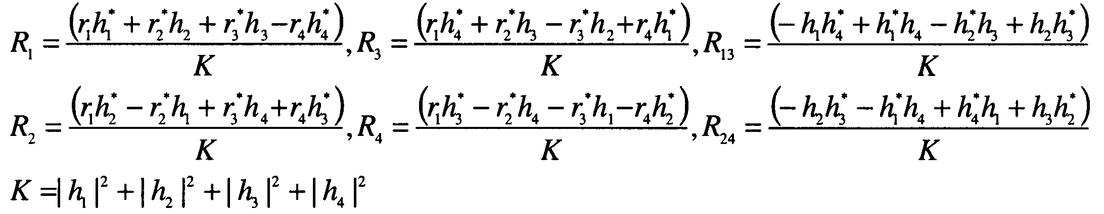
상기의 <수학식 9> 및 <수학식 10>를 이용하면, 수신기에서 상기 <수학식 9>에 따라 x1과 x3의 쌍(pair)을 디코딩하는 부분과 상기 <수학식 10>에 따라 x
2와 x4의 쌍을 디코딩하는 부분을 분리(de-couple)하여, 수신기 구조를 보다 간략화할 수 있다.Using
한편, 입력되는 심볼들이 BPSK(Binary Phase Shift Keying)에 의하여 생성된 경우, 즉 실수 심볼(real symbol)인 경우, 상기와 같이 구성되는 부호화 행렬은 항상 최대의 다이버시티 차수를 가진다. 그러나 복소 성상도(complex constellation)를 이용하는 3차 이상의 심볼매핑 방식, 즉 QPSK(Quadrature Phase Shift Keying), 8PSK(8ary PSK), 16PSK(16ary PSK)를 사용하는 경우에는 전송되는 심볼들이 복소 형태가 되기 때문에 다이버시티 차수가 감소된다. 그러므로 본 발명에서는 4개의 심볼들 중 서로 다른 메트릭 값을 결정하는 2개의 심볼들을 각각 소정 위상값만큼 위상 회전시켜 최대의 다이버시티 차수 4를 얻는다. 그러면 4개의 안테나들을 통해 전송되는 심볼들은 하기의 <수학식 12>과 같은 행렬로 표현된다.On the other hand, when the input symbols are generated by Binary Phase Shift Keying (BPSK), that is, real symbols, the coding matrix constructed as described above always has the maximum diversity order. However, in the case of using the third or more symbol mapping method using complex constellation, that is, quadrature phase shift keying (QPSK), 8 PSK (8ary PSK), and 16PSK (16ary PSK), the transmitted symbols become complex. This reduces the diversity order. Therefore, in the present invention, the

여기에서는 상기 입력 심볼들 s1,s2,s3,s4 중 s1,s
4를 각각 Θ1,Θ4만큼씩 위상 회전하는 부호화 행렬을 도시하였다. 다른 경우 서로 다른 메트릭에 관련되는 심볼 쌍인 s1,s2 또는 s3,s4 또는 s2,s3을 회전시킬 수 있다. 여기서 2개의 심볼들을 각각 회전시키는 위상값들이 서로 다르거나 또는 서로 동일하더라도 다이버시티 차수는 항상 최대로 유지된다.Here is shown the input symbols s 1, s 2, s 3 ,
본 발명에 따라 최대의 다이버시티 차수와 최소의 지연시간을 가지면서, ML 디코딩 설계를 간략화 하는 다른 부호화 행렬들의 일부를 하기의 <수학식 13>에 도시하였다.In accordance with the present invention, some of the other coding matrices that simplify the ML decoding design with maximum diversity order and minimum delay time are shown in Equation 13 below.

여기서 x1,x2,x3,x4는 전송하고자 하는 심볼들 s1,s 2,s3,s4 전체 또는 일부에 반전과 공액을 적용하고 위상 회전시켜 임의로 배열한 것이다.Here, x 1 , x 2 , x 3 , x 4 are randomly arranged by applying inversion and conjugation to all or some of the symbols s 1 , s 2 , s 3 , and s 4 to be transmitted and rotating the phase.
본 발명의 변형된 실시예에서 전송하고자 하는 모든 심볼들은 서로 다른 위상 값만큼 회전될 수 있다. 이러한 점을 고려하면 부호화 행렬은 하기의 <수학식 14>와 같이 일반화된다.In a modified embodiment of the present invention, all symbols to be transmitted may be rotated by different phase values. Considering this point, the coding matrix is generalized as shown in

본 발명의 다른 변형된 실시예에서 부호화 행렬에 임의의 단위 행렬(unitary matrix) U를 곱하여 사용한다. 이러한 경우 수신기에서는 하기의 <수학식 15>에 나타낸 바와 같이, 수신 심볼들에 UH를 곱하여 검출한다.In another modified embodiment of the present invention, the coding matrix is multiplied by an arbitrary unitary matrix U and used. In this case, the receiver detects by multiplying the received symbols by U H , as shown in

이상에서 설명한 바와 같은 부호화 행렬들을 이용하는 송신기와 수신기를 도 3과 도 4에 나타내었다.3 and 4 illustrate a transmitter and a receiver using the coding matrices as described above.
상기 도 3은 본 발명의 일 실시예에 따른 송신기의 구성을 나타낸 블럭도로서, 도시한 바와 같이 직/병렬 변환기(Serial to Parallel Converter)(210)와 위 상 회전기들(Phase Rotators)(220,225)과 부호화기(Encoder)(230)와 4개의 송신 안테나들(240,242,244)로 구성된다.3 is a block diagram showing a configuration of a transmitter according to an embodiment of the present invention, as shown, a serial to
상기 도 3을 참조하면, 상기 직/병렬 변환기(210)는 입력되는 4개의 심볼들 s1,s2,s3,s4를 하나의 블럭으로 묶어 상기 부호화기(230)로 제공한다. 이때 하나의 블럭 중 선택된 2개의 심볼들 s1,s4는 상기 부호화기(230)로 입력되기 전에 상기 위상 회전기들(220,225)에 의해 각각 소정 위상값들 Θ1,Θ4만큼씩 회전된다. 여기서 상기 2개의 심볼들은 수신기에서 서로 다른 메트릭에 관련되도록 선택된다. 상기 부호화기(230)는 상기 위상 회전된 2개의 심볼들을 포함하는 한 블럭의 심볼들을 가지고 각각 4개의 심볼들을 포함하는 4개의 조합들을 구성하여 4개의 시간구간들 동안 상기 4개의 송신 안테나들(240 내지 246)로 전달한다.Referring to FIG. 3, the serial /
여기서 상기 부호화기(230)는 최대의 다이버시티 차수를 얻기 위하여, 상기 입력되는 4개의 복소 심볼들이 각 안테나와 각 시간구간에서 한번씩만 전송되도록 상기 조합들을 구성한다. 또한 상기 부호화기(230)는 각각의 안테나로 전달되는 심볼 시퀀스들의 적어도 일부가 상호간에 직교하도록(orthogonally) 상기 입력 심볼들에 반전(negative)과 공액(conjugate)을 적용하여 상기 조합들을 구성한다. 여기서 상기 입력 심볼들 중 선택된 2개의 심볼들을 위상 회전시키는 것은 상기 입력 심볼들이 복소 심볼인 경우에도 최대의 다이버시티 차수를 얻기 위함이다.In order to obtain the maximum diversity order, the
상기 4개의 안테나들로 전송되는 4개의 조합들을 4x4 행렬로 표현하면, M번째 안테나로는 부호화 행렬의 M번째 열의 심볼들이 순서대로 전달된다. 즉 n번째 시간구간에서 n번째 행의 심볼들이 동시에 4개의 송신 안테나들로 전달된다.When four combinations transmitted to the four antennas are expressed in a 4x4 matrix, the symbols of the Mth column of the coding matrix are sequentially transmitted to the Mth antenna. That is, the symbols of the nth row are transmitted to four transmit antennas at the same time in the nth time interval.
일 예로서 입력되는 4개의 심볼들 s1,s2,s3,s4 중 s1,s4를 각각 Θ1,Θ4만큼 위상 회전하는 경우, 상기 부호화기(230)의 출력은 앞서 언급한 <수학식 12>와 같은 4x4의 부호화 행렬로 나타낼 수 있다. 상기 <수학식 12>에 나타낸 부호화 행렬이 사용되는 경우 제1 시간구간에서는 첫 번째 열의 4개의 심볼들 ![]()
![]()
![]()
![]()
![]()
![]()
![]()
![]()
상기 도 4는 상기 도 3의 송신기로부터 송신된 신호를 수신하는 수신기의 구성을 나타낸 블럭도로서, 여기서 본 발명에 따른 수신기는 독립적으로 동작하는 2개의 ML(Maximum Likelihood) 디코더들(Decoders)(340,345)을 포함하여 구성된다.FIG. 4 is a block diagram showing a configuration of a receiver for receiving a signal transmitted from the transmitter of FIG. 3, wherein the receiver according to the present invention operates two Maximum Likelihood (ML)
상기 도 4를 참조하면, 채널 추정기(Channel Estimator)(320)는 3개의 송신 안테나들(240 내지 246)로부터 수신 안테나들(310, 315)로의 채널 계수들(channel coefficients), 즉 채널 이득들 h1,h2,h3,h4를 추정하며, 심볼 배열기(Symbol Arranger)(330)는 상기 수신 안테나들(310,315) 각각을 통해 4개의 시간구간들 동안 수신되는 신호들 r1,r2,r3,r4를 수집한다.Referring to FIG. 4, the
만일 수신 안테나가 1개라면 상기 심볼 배열기(330)는 4개의 시간구간들 동안의 수신 신호들 r1,r2,r3,r4를 수집한다. 이는 송신기에 의해 한 블럭의 심볼들이 4개의 시간구간들 동안 전송되었기 때문이다. 만일 2개 이상의 수신 안테나들이 사용되는 경우 상기 심볼 배열기(330)는 수신 신호들을 모아 행렬 형태로 구성한다. 여기서 하나의 행에는 하나의 수신 안테나를 통해 수신되는 신호들을 배치하고 하나의 열에는 하나의 시간구간에 수신되는 신호들을 배치한다. 여기에서는 복수개의 수신 안테나들(310,315)을 사용하는 구조를 도시하였으나 아래에서는 설명의 편의를 위하여 하나의 수신 안테나를 사용하는 경우에 대해서 설명할 것이다.If there is only one receiving antenna, the
송신기로부터 전송된 4개의 심볼들 s1,s2,s3,s4를 복원하고자 하는 경우, 상기 디코더들(340,345) 중 제1 디코더(340)는 상기 채널 이득들 및 상기 수신 신호들에 따라 s1과 s3을 검출하며 제2 디코더(345)는 마찬가지 방식으로 s2와 s4를 검출한다. 그러면 상기 디코더들(340,345)에 의해 상기 4개의 심볼들이 동시에 검출된다. 여기서 검출된 심볼들은 원래의 심볼들과 구별하기 위하여 s'으로 표기하였다.In order to recover four symbols s 1 , s 2 , s 3 , and s 4 transmitted from a transmitter, a
이하 앞서 언급한 <수학식 12>의 부호화 행렬을 이용하는 경우, 상기 제1 디코더(340)의 동작에 대해 설명하면, 상기 제1 디코더(340)에서 심볼 발생기(Symbol Generator)(350)는 모든 가능한 s1과 s3의 부조합들(Sub-combinations)을 생성하며, 위상 회전기(Phase Rotator)(360)는 상기 빌생된 심볼들 중 하나인 s1을 송신기에 의해 사용된 것과 동일한 위상값 Θ1만큼 회전시켜 ![]()
![]()
메트릭 계산기(Metric Calculator)(370)는 상기 추정된 채널 이득들 h1,h2,h3,h4와 상기 수신 신호들 r1,r2,r
3,r4를 가지고, 위상 회전된 하나의 심볼을 포함하는 가능한 모든 심볼 부조합들에 대해 <수학식 9>를 계산하여 메트릭 값들(Metric values)을 구한다. 그러면 검출기(380)는 상기 메트릭 값들을 이용하여 최소의 메트릭 값을 가지도록 하는 s1', s3'을 검출한다.A metric calculator 370 has a phase rotated one with the estimated channel gains h 1 , h 2 , h 3 , h 4 and the received signals r 1 , r 2 , r 3 , r 4 . For all possible symbol subcombinations including the symbol of, Equation 9 is calculated to obtain metric values. The
이상과 같은 동작은 상기 제2 디코더(345)에서도 동일하게 이루어진다. 이와 같이 상기 제1 디코더(340)에서는 s1'과 s3'을 검출하고 상기 제2 디코더(345)에서는 s2'와 s4'를 검출하면, 병렬/직렬 변환기(Parallel to Serial Converter)(390)는 상기 검출된 심볼들을 순서대로 나열하여 심볼 조합 s1',s2',s3',s4
'를 출력한다.The above operation is similarly performed in the
상기 도 3 및 도 4와 같이 구성되는 송신기와 수신기에서 심볼들을 위상 회전시키기 위하여 사용되는 위상값은 오류 행렬들(error matrices)의 최소 부호화 이득(minimum coding gain)에 따라 결정되어야 한다. 여기서 오류 행렬이란 수신기에서 잘못 검출된 심볼들과 원래 송신된 심볼들간의 차이를 행렬 형태로 배열한 것이며 최소 부호화 이득은 오류 행렬의 모든 고유값들(eigen values)의 곱을 의미한다.The phase value used to phase rotate the symbols in the transmitter and the receiver configured as shown in FIGS. 3 and 4 should be determined according to the minimum coding gain of the error matrices. In this case, the error matrix is a matrix arrangement of the difference between the symbols incorrectly detected at the receiver and the originally transmitted symbols, and the minimum coding gain is a product of all eigen values of the error matrix.
도 5는 본 발명에서 QPSK의 사용시 2개의 위상값들에 대한 최소 부호화 이득의 변화를 나타낸 시뮬레이션 결과이다. 여기서는 2개의 위상값들이 동일하다고 가정하였으며, 가로 축은 위상값을 나타내고 세로 축은 오류 행렬의 최소 부호화 이 득을 나타낸다. 위상값이 90도의 배수가 되면 최소 부호화 이득은 0이 된다. 이는 QPSK 성상도를 90도만큼 회전시키면 원래의 성상도가 되기 때문이다.5 is a simulation result showing a change in the minimum coding gain for two phase values when using QPSK in the present invention. Here, it is assumed that the two phase values are the same, the horizontal axis represents the phase value and the vertical axis represents the minimum coding gain of the error matrix. If the phase value is a multiple of 90 degrees, the minimum coding gain is zero. This is because rotating the QPSK constellation by 90 degrees results in the original constellation.
상기 도 5에 도시된 결과에 따르면 위상값이 45도 주위에 있을 때 최소 부호화 이득이 평탄하게(flat) 됨을 알 수 있다. 따라서 본 발명에서 바람직한 위상값은 45도이다. 도 6에 일 예로서 45도만큼 위상 회전된 QPSK 성상도를 나타내었다. 도시한 바와 같이 위상 회전된 심볼들은 실수축 또는 허수축 상에 위치하게 된다. 본 발명의 제1 실시예에 따른 바람직한 위상 회전의 범위를 예시하면, QPSK가 사용되는 경우 45도를 중심으로 하여 대략 21도 내지 69도이며, 8PSK(8-ary Phase Shift Keying)가 사용되는 경우에는 대략 21도 내지 24도이고, 16PSK(16-ary PSK)가 사용되는 경우에는 대략 11.25도이다. 그러나 본 발명은 이러한 수치 한정에 의하여 제한되는 것이 아니며 바람직한 위상 회전의 범위는 시스템의 특성 등에 따라 설정되어야 한다.According to the result shown in FIG. 5, it can be seen that the minimum coding gain is flat when the phase value is around 45 degrees. Therefore, the preferred phase value in the present invention is 45 degrees. As an example, FIG. 6 shows the QPSK constellation rotated by 45 degrees. As shown, the phase rotated symbols are located on the real axis or the imaginary axis. Illustrating the preferred range of phase rotation according to the first embodiment of the present invention, when QPSK is used, it is approximately 21 degrees to 69 degrees around 45 degrees, and 8-ary phase shift keying (8PSK) is used. Is approximately 21 degrees to 24 degrees, and approximately 11.25 degrees when 16-PSK (16-ary PSK) is used. However, the present invention is not limited by this numerical limitation and the preferred range of phase rotation should be set according to the characteristics of the system and the like.
도 7은 본 발명에 따른 블럭 부호화 기술을 종래의 다른 기술들과 신호대 잡음비(Signal to Noise Ratio: SNR)에 대한 비트 오류율(Bit Error Rate: BER)의 관점에서 비교한 그래프이다. 여기서 410은 부호화하지 않은 심볼들을 전송하는 경우이고 420은 Tarokh에 의해 열들간에 직교인 8x4 부호화 행렬을 사용하는 경우이고, 430은 Alamouti에 의해 2개의 안테나를 사용하는 경우의 효율이고, 440은 최적화된 위상값 45도를 사용하는 4x4 부호화 행렬을 사용하는 경우이고, 450은 최적화되지 않은 위상값 5도를 사용하는 4x4 부호화 행렬을 사용하는 경우이고, 460은 3개의 송신 안테나들에 대해 4x3 행렬을 사용하는 경우의 효율을 나타낸 것이다. 도시한 바와 같이 본 발명에 따라 최적화된 위상값을 사용하는 블럭 부호는 동일한 신호대 잡음비의 환경에서 보다 낮은 비트 오류율을 가짐을 알 수 있다.FIG. 7 is a graph comparing a block coding technique according to the present invention in terms of a bit error rate (BER) with respect to a signal to noise ratio (SNR). Where 410 is the case of transmitting uncoded symbols, 420 is the case of using 8x4 coding matrix orthogonal between columns by Tarokh, 430 is the efficiency of using 2 antennas by Alamouti, and 440 is optimization In the case of using a 4x4 coding matrix using a phase value of 45 degrees, 450 is a case using a 4x4 coding matrix using an unoptimized phase value of 5 degrees, and 460 denotes a 4x3 matrix for three transmitting antennas. The efficiency at the time of use is shown. As shown, it can be seen that a block code using an optimized phase value according to the present invention has a lower bit error rate in the environment of the same signal-to-noise ratio.
한편 본 발명의 상세한 설명에서는 구체적인 실시예에 관해 설명하였으나, 본 발명의 범위에서 벗어나지 않는 한도 내에서 여러 가지 변형이 가능함은 물론이다. 그러므로 본 발명의 범위는 설명된 실시예에 국한되지 않으며, 후술되는 특허청구의 범위뿐만 아니라 이 특허청구의 범위와 균등한 것들에 의해 정해져야 한다. Meanwhile, in the detailed description of the present invention, specific embodiments have been described, but various modifications are possible without departing from the scope of the present invention. Therefore, the scope of the present invention should not be limited to the described embodiments, but should be defined not only by the scope of the following claims, but also by those equivalent to the scope of the claims.
이상에서 상세히 설명한 바와 같이 동작하는 본 발명에 있어서, 개시되는 발명중 대표적인 것에 의하여 얻어지는 효과를 간단히 설명하면 다음과 같다.In the present invention operating as described in detail above, the effects obtained by the representative ones of the disclosed inventions will be briefly described as follows.
본 발명은 복소 성상도를 사용하는 경우에도 전송율의 손실 없이 최대의 다이버시티 차수를 얻을 수 있으며, 송신 지연시간을 감소시켜 고속 페이딩에 강하다. 또한 부호화 행렬의 열들이 상호간에 직교하도록 하여 디코딩 설계를 간단히 한다.According to the present invention, even when using a complex constellation, the maximum diversity order can be obtained without loss of transmission rate, and the transmission delay time is reduced, which is strong in fast fading. It also simplifies the decoding design by allowing the columns of the coding matrix to be orthogonal to each other.
Claims (21)


Priority Applications (5)
| Application Number | Priority Date | Filing Date | Title |
|---|---|---|---|
| KR1020030001454A KR100605860B1 (en) | 2003-01-09 | 2003-01-09 | Apparatus and method for transmitting in wireless telecommunication system using 4 transmit antennas |
| US10/692,894 US7298797B2 (en) | 2003-01-09 | 2003-10-24 | Transmitter and receiver provided in wireless communication system using four transmitting antennas |
| CNB2003101195827A CN100375417C (en) | 2003-01-09 | 2003-12-04 | Transmitter and receiver in radio communication system using four transmitting antennas |
| EP03078902A EP1437851B1 (en) | 2003-01-09 | 2003-12-08 | Space-time coding using four antennas |
| JP2004004578A JP4064354B2 (en) | 2003-01-09 | 2004-01-09 | Transmitting and receiving apparatus for wireless communication system using four transmitting antennas |
Applications Claiming Priority (1)
| Application Number | Priority Date | Filing Date | Title |
|---|---|---|---|
| KR1020030001454A KR100605860B1 (en) | 2003-01-09 | 2003-01-09 | Apparatus and method for transmitting in wireless telecommunication system using 4 transmit antennas |
Publications (2)
| Publication Number | Publication Date |
|---|---|
| KR20040064154A KR20040064154A (en) | 2004-07-16 |
| KR100605860B1 true KR100605860B1 (en) | 2006-07-31 |
Family
ID=32501494
Family Applications (1)
| Application Number | Title | Priority Date | Filing Date |
|---|---|---|---|
| KR1020030001454A KR100605860B1 (en) | 2003-01-09 | 2003-01-09 | Apparatus and method for transmitting in wireless telecommunication system using 4 transmit antennas |
Country Status (5)
| Country | Link |
|---|---|
| US (1) | US7298797B2 (en) |
| EP (1) | EP1437851B1 (en) |
| JP (1) | JP4064354B2 (en) |
| KR (1) | KR100605860B1 (en) |
| CN (1) | CN100375417C (en) |
Cited By (1)
| Publication number | Priority date | Publication date | Assignee | Title |
|---|---|---|---|---|
| KR101585675B1 (en) | 2014-07-29 | 2016-01-15 | 한국철도기술연구원 | Maximum likelihood detecting receiver using iterative algorithm for transmit diversity mode and maximum likelihood detecting method thereof |
Families Citing this family (15)
| Publication number | Priority date | Publication date | Assignee | Title |
|---|---|---|---|---|
| KR100640349B1 (en) * | 2003-01-02 | 2006-10-30 | 삼성전자주식회사 | Transmitting and receiving apparatus for wireless telecommunication system having 3 transmit antennas |
| CN100373809C (en) * | 2004-07-26 | 2008-03-05 | 电子科技大学 | Method for constructing time-space group code in wireless communication |
| KR100719840B1 (en) * | 2004-11-04 | 2007-05-18 | 삼성전자주식회사 | Apparatus and method of time space frequency block coding |
| KR100720872B1 (en) * | 2004-11-04 | 2007-05-22 | 삼성전자주식회사 | Transmitting and receiving apparatus and method employing apparatus and method of space time block code for increasing performance |
| KR100639407B1 (en) * | 2005-03-05 | 2006-10-30 | 재단법인서울대학교산학협력재단 | A method for encoding a message using diagonally weighted space-time trellis code depending on bit feedback |
| EA014591B1 (en) | 2005-09-01 | 2010-12-30 | Шарп Кабусики Кайся | Transmission control method in wireless communication system |
| EP1944893B1 (en) | 2005-10-31 | 2020-01-01 | Sharp Kabushiki Kaisha | Radio transmitter, radio communication system, and radio transmission method |
| EA012497B1 (en) * | 2005-10-31 | 2009-10-30 | Шарп Кабусики Кайся | Terminal apparatus, base station apparatus and communication system |
| EP2439861B1 (en) * | 2005-12-20 | 2013-10-02 | Huawei Technologies Co., Ltd. | Transmitter apparatus for communications system using multiple antennas |
| JP4658146B2 (en) * | 2005-12-26 | 2011-03-23 | シャープ株式会社 | Wireless transmitter and wireless transmission method |
| KR101003433B1 (en) * | 2006-02-01 | 2010-12-23 | 엘지전자 주식회사 | A method of transmitting data using superpostion modulation in a wireless communication system |
| US8644407B2 (en) * | 2008-06-23 | 2014-02-04 | Blackberry Limited | Apparatus, and associated method of phase-offset modulation, for space-time coded wireless communication systems |
| CN105763288B (en) * | 2014-12-16 | 2019-08-30 | 电信科学技术研究院 | Configuration and determining method, equipment based on the multi-user coding mode of coding superposition |
| CN109541700A (en) * | 2018-10-25 | 2019-03-29 | 深圳市华讯方舟太赫兹科技有限公司 | Safety check instrument system, millimeter wave transceiving module and its millimeter-wave signal generate component |
| CN113038097B (en) * | 2021-02-08 | 2022-07-26 | 北京航空航天大学 | Projection method, device and storage medium |
Family Cites Families (14)
| Publication number | Priority date | Publication date | Assignee | Title |
|---|---|---|---|---|
| JPH08111651A (en) * | 1994-10-11 | 1996-04-30 | Miyoshi Denshi Kk | High sensitivity transmitter-receiver |
| CN1292175A (en) * | 1998-03-03 | 2001-04-18 | 美国电报电话公司 | Decoding of space-time coded signals for wireless communication |
| EP1033004A1 (en) * | 1998-09-18 | 2000-09-06 | Hughes Electronics Corporation | Method and constructions for space-time codes for psk constellations for spatial diversity in multiple-element antenna systems |
| US6317411B1 (en) * | 1999-02-22 | 2001-11-13 | Motorola, Inc. | Method and system for transmitting and receiving signals transmitted from an antenna array with transmit diversity techniques |
| KR100526499B1 (en) * | 2000-08-22 | 2005-11-08 | 삼성전자주식회사 | Apparatus for transmit diversity for more than two antennas and method thereof |
| US7006579B2 (en) * | 2000-09-29 | 2006-02-28 | Nokia Corporation | ISI-robust slot formats for non-orthogonal-based space-time block codes |
| KR100614410B1 (en) * | 2000-12-01 | 2006-08-18 | 주식회사 케이티 | The Apparatus and Method for Detecting the Signals of Space-Time Coding based Transmit Diversity |
| BR0208208A (en) * | 2001-03-28 | 2006-12-12 | Nokia Corp | A method and apparatus for encoding phase jump and special time signals for transmission by a plurality of antennas |
| JP4387791B2 (en) * | 2001-05-25 | 2009-12-24 | リージェンツ オブ ザ ユニバーシティ オブ ミネソタ | Space-time coded transmission method in a wireless communication network |
| KR100763378B1 (en) * | 2001-07-27 | 2007-10-05 | 엘지전자 주식회사 | Method for transmitting/receiving using plurality of antennas, system for the same |
| WO2003023996A1 (en) * | 2001-09-12 | 2003-03-20 | Infineon Technologies Ag | Cdma wireless systems |
| US7184488B2 (en) * | 2002-03-15 | 2007-02-27 | Lucent Technologies Inc. | Quasi-orthogonal space-time codes |
| US8218609B2 (en) * | 2002-10-25 | 2012-07-10 | Qualcomm Incorporated | Closed-loop rate control for a multi-channel communication system |
| KR100557085B1 (en) * | 2003-01-09 | 2006-03-03 | 삼성전자주식회사 | Receiving apparatus for wireless telecommunication system using at least 3 transmit antennas |
-
2003
- 2003-01-09 KR KR1020030001454A patent/KR100605860B1/en not_active IP Right Cessation
- 2003-10-24 US US10/692,894 patent/US7298797B2/en active Active
- 2003-12-04 CN CNB2003101195827A patent/CN100375417C/en not_active Expired - Lifetime
- 2003-12-08 EP EP03078902A patent/EP1437851B1/en not_active Expired - Fee Related
-
2004
- 2004-01-09 JP JP2004004578A patent/JP4064354B2/en not_active Expired - Lifetime
Cited By (1)
| Publication number | Priority date | Publication date | Assignee | Title |
|---|---|---|---|---|
| KR101585675B1 (en) | 2014-07-29 | 2016-01-15 | 한국철도기술연구원 | Maximum likelihood detecting receiver using iterative algorithm for transmit diversity mode and maximum likelihood detecting method thereof |
Also Published As
| Publication number | Publication date |
|---|---|
| US20040137951A1 (en) | 2004-07-15 |
| JP4064354B2 (en) | 2008-03-19 |
| CN1518264A (en) | 2004-08-04 |
| US7298797B2 (en) | 2007-11-20 |
| EP1437851B1 (en) | 2013-02-20 |
| KR20040064154A (en) | 2004-07-16 |
| CN100375417C (en) | 2008-03-12 |
| EP1437851A2 (en) | 2004-07-14 |
| EP1437851A3 (en) | 2010-12-22 |
| JP2004222281A (en) | 2004-08-05 |
Similar Documents
| Publication | Publication Date | Title |
|---|---|---|
| KR100640349B1 (en) | Transmitting and receiving apparatus for wireless telecommunication system having 3 transmit antennas | |
| KR100630108B1 (en) | Transmitting and receiving apparatus for supporting transmission antenna diversity using space-time block code | |
| US7483476B2 (en) | Method and system for utilizing space-time and space-frequency codes for multi-input multi-output frequency selective fading channels | |
| US7643569B2 (en) | Space-time trellis code for orthogonal frequency division multiplexing (OFDM) | |
| KR100605860B1 (en) | Apparatus and method for transmitting in wireless telecommunication system using 4 transmit antennas | |
| JP2007166668A (en) | Transmitting and receiving apparatus for supporting transmit antenna diversity using space-time block code | |
| EP2113147B1 (en) | Scaled and rotated alamouti coding | |
| KR100671231B1 (en) | APPARATUS AND METHOD OF SPACE TIME BLOCK CODE FOR even TX ANTENNAS WITH FULL RATE AND FULL DIVERSITY | |
| KR101159262B1 (en) | Method for the multi-antennae emission of a signal by unitary space-time codes, receiving method, and corresponding signal | |
| KR100557085B1 (en) | Receiving apparatus for wireless telecommunication system using at least 3 transmit antennas | |
| KR100780364B1 (en) | Apparatus and method of space time block code for increasing performance | |
| JP2008511245A (en) | Apparatus and method for space-time block coding with maximum diversity and maximum transmission rate using two transmission antennas | |
| Ren et al. | Block-orthogonal space-time codes with decoding complexity reduction | |
| Nisirat et al. | Performance Improvement of Space-Time Block Coding Using Flexible Feedback Bits Over Rician Channels | |
| Sethi | Analysis of Different Space Time Block Codes with Linear Receiver for Various Modulation Technique | |
| Bin et al. | MIMO-OFDM detection based on Monte Carlo probabilistic data association |
Legal Events
| Date | Code | Title | Description |
|---|---|---|---|
| A201 | Request for examination | ||
| E902 | Notification of reason for refusal | ||
| E90F | Notification of reason for final refusal | ||
| E701 | Decision to grant or registration of patent right | ||
| GRNT | Written decision to grant | ||
| FPAY | Annual fee payment |
Payment date: 20130627 Year of fee payment: 8 |
|
| FPAY | Annual fee payment |
Payment date: 20140627 Year of fee payment: 9 |
|
| FPAY | Annual fee payment |
Payment date: 20150629 Year of fee payment: 10 |
|
| LAPS | Lapse due to unpaid annual fee |