KR100561094B1 - Loudspeaker device and method for driving the same, and audio signal transmitter/receiver - Google Patents
Loudspeaker device and method for driving the same, and audio signal transmitter/receiver Download PDFInfo
- Publication number
- KR100561094B1 KR100561094B1 KR1019997008033A KR19997008033A KR100561094B1 KR 100561094 B1 KR100561094 B1 KR 100561094B1 KR 1019997008033 A KR1019997008033 A KR 1019997008033A KR 19997008033 A KR19997008033 A KR 19997008033A KR 100561094 B1 KR100561094 B1 KR 100561094B1
- Authority
- KR
- South Korea
- Prior art keywords
- signal
- frequency
- audio signal
- output
- ultrasonic wave
- Prior art date
Links
- 230000005236 sound signal Effects 0.000 title claims abstract description 122
- 238000000034 method Methods 0.000 title claims description 55
- 238000007781 pre-processing Methods 0.000 claims description 30
- 241001442234 Cosa Species 0.000 claims description 5
- 230000006870 function Effects 0.000 description 23
- 238000010586 diagram Methods 0.000 description 11
- 230000005540 biological transmission Effects 0.000 description 4
- 230000000694 effects Effects 0.000 description 3
- 238000003384 imaging method Methods 0.000 description 3
- 235000013527 bean curd Nutrition 0.000 description 2
- 238000004891 communication Methods 0.000 description 2
- 238000001514 detection method Methods 0.000 description 2
- 210000005069 ears Anatomy 0.000 description 2
- 238000005286 illumination Methods 0.000 description 2
- 230000028327 secretion Effects 0.000 description 2
- XLYOFNOQVPJJNP-UHFFFAOYSA-N water Substances O XLYOFNOQVPJJNP-UHFFFAOYSA-N 0.000 description 2
- NAWXUBYGYWOOIX-SFHVURJKSA-N (2s)-2-[[4-[2-(2,4-diaminoquinazolin-6-yl)ethyl]benzoyl]amino]-4-methylidenepentanedioic acid Chemical compound C1=CC2=NC(N)=NC(N)=C2C=C1CCC1=CC=C(C(=O)N[C@@H](CC(=C)C(O)=O)C(O)=O)C=C1 NAWXUBYGYWOOIX-SFHVURJKSA-N 0.000 description 1
- 240000007594 Oryza sativa Species 0.000 description 1
- 235000007164 Oryza sativa Nutrition 0.000 description 1
- 239000000969 carrier Substances 0.000 description 1
- 230000002349 favourable effect Effects 0.000 description 1
- 238000009413 insulation Methods 0.000 description 1
- 239000004973 liquid crystal related substance Substances 0.000 description 1
- 239000000463 material Substances 0.000 description 1
- 230000003287 optical effect Effects 0.000 description 1
- 230000010287 polarization Effects 0.000 description 1
- 235000009566 rice Nutrition 0.000 description 1
- 229910052709 silver Inorganic materials 0.000 description 1
- 239000004332 silver Substances 0.000 description 1
Images


Classifications
-
- H—ELECTRICITY
- H04—ELECTRIC COMMUNICATION TECHNIQUE
- H04R—LOUDSPEAKERS, MICROPHONES, GRAMOPHONE PICK-UPS OR LIKE ACOUSTIC ELECTROMECHANICAL TRANSDUCERS; DEAF-AID SETS; PUBLIC ADDRESS SYSTEMS
- H04R1/00—Details of transducers, loudspeakers or microphones
- H04R1/20—Arrangements for obtaining desired frequency or directional characteristics
- H04R1/32—Arrangements for obtaining desired frequency or directional characteristics for obtaining desired directional characteristic only
- H04R1/40—Arrangements for obtaining desired frequency or directional characteristics for obtaining desired directional characteristic only by combining a number of identical transducers
- H04R1/403—Arrangements for obtaining desired frequency or directional characteristics for obtaining desired directional characteristic only by combining a number of identical transducers loud-speakers
-
- H—ELECTRICITY
- H04—ELECTRIC COMMUNICATION TECHNIQUE
- H04R—LOUDSPEAKERS, MICROPHONES, GRAMOPHONE PICK-UPS OR LIKE ACOUSTIC ELECTROMECHANICAL TRANSDUCERS; DEAF-AID SETS; PUBLIC ADDRESS SYSTEMS
- H04R3/00—Circuits for transducers, loudspeakers or microphones
-
- H—ELECTRICITY
- H04—ELECTRIC COMMUNICATION TECHNIQUE
- H04R—LOUDSPEAKERS, MICROPHONES, GRAMOPHONE PICK-UPS OR LIKE ACOUSTIC ELECTROMECHANICAL TRANSDUCERS; DEAF-AID SETS; PUBLIC ADDRESS SYSTEMS
- H04R3/00—Circuits for transducers, loudspeakers or microphones
- H04R3/12—Circuits for transducers, loudspeakers or microphones for distributing signals to two or more loudspeakers
-
- H—ELECTRICITY
- H04—ELECTRIC COMMUNICATION TECHNIQUE
- H04R—LOUDSPEAKERS, MICROPHONES, GRAMOPHONE PICK-UPS OR LIKE ACOUSTIC ELECTROMECHANICAL TRANSDUCERS; DEAF-AID SETS; PUBLIC ADDRESS SYSTEMS
- H04R2205/00—Details of stereophonic arrangements covered by H04R5/00 but not provided for in any of its subgroups
- H04R2205/022—Plurality of transducers corresponding to a plurality of sound channels in each earpiece of headphones or in a single enclosure
-
- H—ELECTRICITY
- H04—ELECTRIC COMMUNICATION TECHNIQUE
- H04R—LOUDSPEAKERS, MICROPHONES, GRAMOPHONE PICK-UPS OR LIKE ACOUSTIC ELECTROMECHANICAL TRANSDUCERS; DEAF-AID SETS; PUBLIC ADDRESS SYSTEMS
- H04R2217/00—Details of magnetostrictive, piezoelectric, or electrostrictive transducers covered by H04R15/00 or H04R17/00 but not provided for in any of their subgroups
- H04R2217/03—Parametric transducers where sound is generated or captured by the acoustic demodulation of amplitude modulated ultrasonic waves
-
- H—ELECTRICITY
- H04—ELECTRIC COMMUNICATION TECHNIQUE
- H04R—LOUDSPEAKERS, MICROPHONES, GRAMOPHONE PICK-UPS OR LIKE ACOUSTIC ELECTROMECHANICAL TRANSDUCERS; DEAF-AID SETS; PUBLIC ADDRESS SYSTEMS
- H04R2499/00—Aspects covered by H04R or H04S not otherwise provided for in their subgroups
- H04R2499/10—General applications
- H04R2499/15—Transducers incorporated in visual displaying devices, e.g. televisions, computer displays, laptops
Abstract
음원에서 출력되는 오디오신호를 변조기에 의해 가청대역보다 높은 주파수대역의 신호로 변조하고, 이 변조기에 의해 주파수변조된 신호에 의해 초음파발생소자를 구동한다. 변조기는 음원에서 출력되는 오디오신호를 제 1주파수로 변조한 신호와 제 1주파수와는 다른 제 2주파수로 변조한 신호로 변환한다. 이와 같이 변조된 신호에 의해 초음파발생소자가 구동됨으로써, 초음파발생소자에서 방사되는 제 1주파수의 초음파와 제 2주파수의 초음파의 차에 상당하는 주파수성분이 가청음으로서 청취된다.The audio signal output from the sound source is modulated by a modulator into a signal having a frequency band higher than that of an audible band, and the ultrasonic generator is driven by the signal modulated by the modulator. The modulator converts an audio signal output from a sound source into a signal modulated with a first frequency and a signal modulated with a second frequency different from the first frequency. As the ultrasonic wave generator is driven by the modulated signal as described above, a frequency component corresponding to the difference between the ultrasonic wave at the first frequency and the ultrasonic wave at the second frequency emitted from the ultrasonic wave generator is heard as an audible sound.
초음파발생소자에서 초음파가 발생되므로, 초지향성이 실현된다.Since ultrasonic waves are generated in the ultrasonic wave generating element, superdirectionality is realized.
Description
본 발명은, 초음파발생소자를 이용하여 오디오신호의 재생을 행하는 스피커장치 및 그 구동방법과 초음파발생소자를 이용한 오디오신호 송수신장치에 관한 것이다.The present invention relates to a speaker device for reproducing an audio signal using an ultrasonic wave generating element, a driving method thereof, and an audio signal transmitting and receiving apparatus using the ultrasonic wave generating element.
종래, 스피커장치로서는 진동판을 진동시키고, 이 진동판에서 공기중에 방출되는 음을 청취하도록 구성된 것이 널리 이용되고 있다. 이런 종류의 스피커장치는, 20Hz∼20KHz 정도의 가청대역의 오디오신호에 의해 진동판을 진동시키고, 이 진동판에서 직접 공기중에 음파를 방출하도록 구성되어 있다.Background Art Conventionally, a speaker device configured to vibrate a diaphragm and to listen to sound emitted in the air from the diaphragm has been widely used. This type of speaker device is configured to vibrate a diaphragm by an audio signal in an audible band of about 20 Hz to 20 KHz, and emit sound waves directly into the air from the diaphragm.
그런데, 진동판을 가청대역의 오디오신호로 구동하도록 한 스피커장치는, 진동판을 중심으로 하여 공기중에 넓혀짐을 가지고 음이 방출된다. 이런 종류의 스피커장치는, 넓은 공간에 음을 방출하는 경우에 사용하여 유용하다.By the way, the speaker device which drives the diaphragm with an audio signal of an audible band spreads in air centering on a diaphragm, and sound is emitted. This kind of speaker device is useful when used to emit sound in a large space.
그러나, 이런 종류의 스피커장치에 있어서는, 특정의 청취자에게만 향해서 음을 방출할 수 없다.However, in this kind of speaker device, sound cannot be emitted only to a specific listener.
또, 재생음을 개인에게만 청취가능하게 하기 위해, 두부(頭部)나 귀밥에 장착하는 헤드폰이나 이어폰이 사용되고 있다. 이런 종류의 헤드폰이나 이어폰도 진동판을 가청대역의 오디오신호에 의해 구동하는 것이며, 진동판을 중심으로 하여 공기중에 넓혀짐을 가지고 음이 방출된다. 헤드폰이나 이어폰은, 비화성을 확보하기 위해 스피커유닛을 밀폐한 상태에서 두부나 귀밥에 장착할 필요가 있다.Moreover, in order to be able to listen to a reproduction sound only to an individual, the headphone and earphone attached to tofu or ear rice are used. Headphones and earphones of this type also drive the diaphragm by an audio signal of an audible band, and sound is emitted with the diaphragm widening in the air. Headphones and earphones need to be mounted on tofu or ear buds with the speaker unit sealed to ensure incombustibility.
본 발명의 목적은, 신규한 구동방식을 이용하여 초지향성을 가지고 음의 방출을 가능하게 하는 스피커장치 및 그 구동방법을 제공하는데 있다.SUMMARY OF THE INVENTION An object of the present invention is to provide a speaker device and a method of driving the same, which are capable of emitting sound with superdirectionality by using a novel driving method.
본 발명의 다른 목적은, 비화기능을 가지고 음의 방출을 행할 수 있는 스피커장치 및 그 구동방법을 제공하는데 있다.Another object of the present invention is to provide a speaker device capable of emitting sound with a sparking function and a driving method thereof.
본 발명의 또한 다른 목적은, 동시에 복수의 위치에서 다른 음을 청취하는 것을 가능하게 하는 스피커장치 및 그 구동방법을 제공하는데 있다.It is still another object of the present invention to provide a speaker device and a driving method thereof, which make it possible to simultaneously listen to different sounds in a plurality of positions.
본 발명의 또한 다른 목적은, 자재스런 위치에 음상정위를 설정할 수 있는 스피커장치 및 그 구동방법을 제공하는데 있다.It is still another object of the present invention to provide a speaker device and a driving method thereof capable of setting sound phase in a material position.
본 발명의 또한 다른 목적은, 비화기능의 향상을 도모하여 오디오신호의 송수신을 행할 수 있는 오디오신호 송수신장치를 제공하는데 있다.It is still another object of the present invention to provide an audio signal transmitting and receiving device capable of transmitting and receiving audio signals by improving the secretion function.
이와 같은 목적을 달성하기 위해, 본 발명에 관계되는 스피커장치는 오디오신호를 적어도 가청 주파수대역보다도 높은 주파수대역의 신호로 주파수변조하는 변조기와, 이 변조기로부터의 출력신호에 의해 구동되는 적어도 하나의 초음파발생소자를 갖추어서 이룬다.In order to achieve the above object, the speaker device according to the present invention comprises a modulator for frequency modulating an audio signal into a signal having a frequency band higher than at least an audible frequency band, and at least one ultrasonic wave driven by an output signal from the modulator. It is achieved by having a generating element.
변조기는, 오디오신호를 제 1주파수에 의거하여 주파수변조된 제 1신호와, 상기 오디오신호를 제 1주파수와는 다른 주파수의 제 2주파수에 의거하여 주파수변 조된 제 2신호로 변조한다.The modulator modulates the audio signal into a first signal frequency modulated based on a first frequency and a second signal frequency modulated based on a second frequency of a frequency different from the first frequency.
또, 본 발명에 관계되는 스피커장치는, 복수의 초음파발생소자를 갖추고, 이들 복수의 초음파발생소자중의 일부의 초음파소자에는 제 1신호가 공급되는 동시에, 남은 초음파발생소자에는 제 2신호가 공급된다.Further, the speaker device according to the present invention includes a plurality of ultrasonic wave generating elements, wherein a first signal is supplied to some of the ultrasonic wave elements among the plurality of ultrasonic wave generating elements, and a second signal is supplied to the remaining ultrasonic wave generating elements. do.
또한, 본 발명에 관계되는 스피커장치는, 또한 오디오신호를 미분하는 미분처리부를 갖추고 있다. 여기서 변조기는, 제 1 및 제 2변조부를 갖추고, 제 1 및 제 2변조부의 어느 한편의 변조부에는 미분처리부로부터의 출력신호가 공급되는 동시에, 타편의 변조부에는 미분처리부로부터의 출력신호의 극성을 반전시킨 신호가 공급된다.In addition, the speaker device according to the present invention further includes a differential processing unit for differentiating an audio signal. Here, the modulator has a first and a second modulator, wherein one of the first and second modulators is supplied with an output signal from the differential processor, while the other modulator has a polarity of the output signal from the differential processor. The signal inverted is supplied.
그리고 또, 본 발명에 관계되는 스피커장치는, 또한 제 1 및 제 2변조부중의 어느 한편의 변조부에 미분처리부로부터의 출력신호의 직류레벨을 시프트시킨 신호를 공급하는 제 1회로부와, 타편의 변조부에 미분처리부로부터의 출력신호의 극성을 반전시키고, 또한 직류레벨을 시프트시킨 신호를 공급하는 제 2회로부를 갖추고 있다.The speaker device according to the present invention further includes a first circuit section for supplying a signal to which a DC level of the output signal from the differential processing section is shifted to one of the first and second modulators; The modulation section includes a second circuit section for supplying a signal inverting the polarity of the output signal from the differential processing section and shifting the DC level.
그리고 또, 본 발명에 관계되는 스피커장치는, 또한 오디오신호에 전처리를 실시하는 전처리회로를 갖추고있다. 여기서 변조기는, 또한 제 1변조부로부터의 출력신호를 반송파로서 전처리회로로부터의 출력신호를 진폭변조하는 제 1진폭변조부와 상기 제 2변조부로부터의 출력신호를 반송파로서 전처리회로로부터의 출력신호를 진폭변조하는 제 2진폭변조부를 갖추고있다.In addition, the speaker device according to the present invention further includes a preprocessing circuit for preprocessing the audio signal. The modulator further includes an output signal from the pre-processing circuit as a carrier and a first amplitude modulator for amplitude-modulating the output signal from the first processing unit as the carrier wave and the output signal from the second modulator as the carrier wave. And a second amplitude modulator for amplitude modulation.
본 발명에 관계되는 스피커장치는, 또한 변조기와 초음파발생소자와의 사이 에 배치되는 보정필터를 갖추고있다. 이 보정필터는, 변조기에서 출력되는 출력신호중 초음파발생소자의 공진주파수 성분을 억압한다.The speaker device according to the present invention further comprises a correction filter arranged between the modulator and the ultrasonic wave generating element. This correction filter suppresses the resonant frequency component of the ultrasonic wave generating element among the output signals output from the modulator.
또, 본 발명에 관계되는 스피커장치는 제 1 및 제 2변조부를 갖추고, 제 1 및 제 2변조부의 어느 한편의 변조부에는 오디오신호가 공급되는 동시에, 타편의 변조에는 오디오신호를 반전시킨 신호가 공급되고, 오디오신호를 적어도 가청주파수대역보다도 높은 주파수의 신호로 주파수변조하는 변조기와, 이 변조기로부터의 출력신호에 의해 구동되는 초음파발생부를 갖춘다. 초음파발생부는, 제 1변조부로부터의 출력신호에 의거하여 구동되는 복수의 초음파발생소자로 이루는 제 1발생부와, 제 2변조부로부터의 출력신호에 의거하여 구동되는 복수의 초음파발생소자로 이루는 제 2발생부를 가지고 있다.The speaker device according to the present invention has a first and a second modulator, and an audio signal is supplied to either of the modulators of the first and second modulators, and a signal obtained by inverting the audio signal is provided to the other side of the modulator. And a modulator for frequency modulating the audio signal into a signal having a frequency higher than at least an audible frequency band, and an ultrasonic wave generator driven by the output signal from the modulator. The ultrasonic generator comprises a first generator comprising a plurality of ultrasonic generators driven based on an output signal from the first modulator, and a plurality of ultrasonic generators driven based on the output signal from the second modulator. It has a 2nd generation part.
또, 본 발명에 관계되는 오디오신호 송수신장치는, 오디오신호를 미분한 신호로 반송파를 주파수변조하는 변조기와, 이 변조기로부터의 출력신호에 의거하여 구동되는 초음파발생부와, 이 초음파발생부에서 출력되는 음파를 검출하는 마이크로폰으로부터의 출력신호에 역코사인 개시처리를 실시하는 연산부를 갖추고 있다.In addition, the audio signal transmitting and receiving apparatus according to the present invention includes a modulator for frequency-modulating a carrier wave with a differential signal of an audio signal, an ultrasonic generator driven on the basis of an output signal from the modulator, and an output from the ultrasonic generator. And an arithmetic unit for performing inverse cosine start processing on the output signal from the microphone for detecting the sound wave.
이 오디오신호 송수신장치를 구성하는 마이크로폰은, 초음파발생부에서 출력되는 가청주파수대역의 음파를 검출한다.The microphone constituting the audio signal transmitting and receiving device detects sound waves in the audible frequency band output from the ultrasonic wave generator.
또한, 본 발명에 관계되는 초음파발생소자를 가지는 스피커장치의 구동방법은, 입력된 오디오신호를 적어도 가청주파수대역보다도 높은 주파수대역의 신호로 주파수변조하고, 이어서 주파수변조된 신호에 의해 초음파발생소자를 구동한다.In addition, the driving method of the speaker device having the ultrasonic wave generating element according to the present invention is to frequency modulate the input audio signal into a signal of a frequency band at least higher than the audible frequency band, and then the ultrasonic wave generating element is changed by the frequency modulated signal. Drive.
이 구동방법에 있어서는, 오디오신호를 제 1주파수에 의거하여 주파수변조된 제 1신호와, 오디오신호를 제 1주파수와는 다른 제 2주파수에 의거하여 주파수변조된 제 2신호로 변조한다.In this driving method, the audio signal is modulated into a first signal frequency-modulated based on the first frequency, and the audio signal into a second signal frequency-modulated based on a second frequency different from the first frequency.
본 발명의 또 다른 목적은, 본 발명에 의해 얻어지는 구체적인 이점은, 이하에 설명되는 실시예의 설명에서 한층 명백히 될 것이다.It is still another object of the present invention, the specific advantages obtained by the present invention will become more apparent from the description of the embodiments described below.
도 1은 본 발명에 관계되는 스피커장치의 기본적인 구성을 나타내는 회로도이다.1 is a circuit diagram showing a basic configuration of a speaker device according to the present invention.
도 2는 본 발명에 관계되는 스피커장치의 회로도이다.2 is a circuit diagram of a speaker device according to the present invention.
도 3은 본 발명에 관계되는 스피커장치를 구성하는 초음파발생기의 배열의 일예를 나타내는 평면도이다.3 is a plan view showing an example of the arrangement of the ultrasonic generators constituting the speaker device according to the present invention.
도 4는 본 발명에 관계되는 스피커장치를 구성하는 초음파발생기의 배열의 다른 예를 나타내는 평면도이다.4 is a plan view showing another example of the arrangement of the ultrasonic generators constituting the speaker device related to the present invention.
도 5는 도 4에 나타내는 스피커장치의 지향특성을 나타내는 특성도이다.FIG. 5 is a characteristic diagram showing the directing characteristics of the speaker device shown in FIG. 4. FIG.
도 6은 본 발명에 관계되는 스피커장치의 다른 예를 나타내는 회로도이다.6 is a circuit diagram showing another example of the speaker device according to the present invention.
도 7은 본 발명에 관계되는 스피커장치의 또 다른 예를 나타내는 회로도이다.7 is a circuit diagram showing still another example of the speaker device according to the present invention.
도 8은 본 발명에 관계되는 스피커장치를 이용한 오디오신호 송신장치를 나타내는 회로도이다.8 is a circuit diagram showing an audio signal transmission apparatus using the speaker apparatus according to the present invention.
도 9는 전처리회로를 구성하는 DSP의 기능을 나타내는 블록도이다.9 is a block diagram showing the functions of the DSP constituting the preprocessing circuit.
도 10은 전처리회로를 구성하는 DSP의 기능을 나타내는 블록도이다.Fig. 10 is a block diagram showing the function of the DSP constituting the preprocessing circuit.
도 11은 전처리회로를 구성하는 DSP의 기능을 나타내는 블록도이다.Fig. 11 is a block diagram showing the functions of the DSP constituting the preprocessing circuit.
도 12는 보정필터를 구비하는 스피커장치의 회로구성을 나타내는 블록도이다.12 is a block diagram showing a circuit configuration of a speaker device including a correction filter.
도 13은 보정필터를 구비하는 스피커장치의 회로구성을 나타내는 블록도이다.Fig. 13 is a block diagram showing the circuit configuration of a speaker device including a correction filter.
도 14는 오디오대역에서의 스피커특성의 보정원리를 설명하기 위한 도면이다.14 is a view for explaining the principle of correction of the speaker characteristics in the audio band.
도 15는 본 발명에 관계되는 스피커장치를 자동차내의 룸미러에 부착하고, 핸드프리방식의 통신장치의 음성입출력장치를 구성한 예를 나타내는 사시도이다.Fig. 15 is a perspective view showing an example in which a speaker device according to the present invention is attached to a room mirror in an automobile and constitutes a voice input / output device of a hand-free communication device.
도 16은 본 발명에 관계되는 스피커장치를 회의시스템에 적용한 예를 나타내는 사시도이다.Fig. 16 is a perspective view showing an example in which the speaker device according to the present invention is applied to a conference system.
도 17은 본 발명에 관계되는 스피커장치를 텔레비전형 전화장치에 적용한 예를 나타내는 사시도이다.Fig. 17 is a perspective view showing an example in which the speaker device according to the present invention is applied to a television-type telephone apparatus.
도 18은 본 발명에 관계되는 스피커장치를 탈것에 짜넣어지는 음향장치에 적용한 예를 나타내는 사시도이다.18 is a perspective view showing an example in which the speaker device according to the present invention is applied to an acoustic device incorporated in a vehicle.
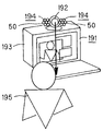
도 19는 본 발명에 관계되는 스피커장치를 투사형의 비디오 프로젝터에 적용한 예를 나타내는 사시도이다.19 is a perspective view showing an example in which the speaker device according to the present invention is applied to a projection type video projector.
도 20은 본 발명에 관계되는 스피커장치를 영상음향장치에 적용한 예를 나타내는 사시도이다.20 is a perspective view showing an example in which the speaker apparatus according to the present invention is applied to a video sound apparatus.
도 21은 본 발명에 관계되는 스피커장치를 오버헤드 프로젝터에 적용한 예를 나타내는 사시도이다.21 is a perspective view illustrating an example in which the speaker device according to the present invention is applied to an overhead projector.
도 22는 본 발명에 관계되는 스피커장치를 다언어의 정보가 기록된 정보기록매체를 재생하는 재생기에 적용한 예를 나타내는 사시도이다.Fig. 22 is a perspective view showing an example in which the speaker device according to the present invention is applied to a player for reproducing an information recording medium on which multilingual information is recorded.
도 23은 본 발명에 관계되는 스피커장치를 2화면형의 텔레비전 수상기에 적용한 예를 나타내는 사시도이다.Fig. 23 is a perspective view showing an example in which the speaker device according to the present invention is applied to a two-screen television receiver.
도 24는 본 발명에 관계되는 스피커장치를 텔레비전 수상기에 적용한 예를 나타내는 사시도이다.24 is a perspective view showing an example in which the speaker device according to the present invention is applied to a television receiver.
도 25는 본 발명에 관계되는 스피커장치를 미술관이나 박물관의 전시실에 적용한 예를 나타내는 사시도이다.25 is a perspective view illustrating an example in which the speaker device according to the present invention is applied to an exhibition hall of an art gallery or a museum.
도 26은 본 발명에 관계되는 스피커장치의 다른 구성예를 나타내는 사시도이다.Fig. 26 is a perspective view showing another configuration example of the speaker device according to the present invention.
도 27은 본 발명에 관계되는 스피커장치에 추미기능을 부여하여 텔레비전 수상기에 설치한 예를 나타내는 사시도이다.Fig. 27 is a perspective view showing an example in which the speaker device according to the present invention is provided with a homing function and installed on a television receiver.
도 28은 본 발명에 관계되는 스피커장치에 추미기능을 부여하여 텔레비전 수상기에 설치한 다른 예를 나타내는 사시도이다.Fig. 28 is a perspective view showing another example in which the speaker device according to the present invention is provided with a homing function and installed on a television receiver.
이하, 본 발명에 관계되는 스피커장치 및 이 스피커장치의 구동방법과 이 스피커장치를 이용한 오디오신호 송신장치를 설명한다.Hereinafter, a speaker device according to the present invention, a driving method of the speaker device, and an audio signal transmission device using the speaker device will be described.
본 발명에 관계되는 스피커장치의 기본적인 구성을 도 1을 참조하여 설명한 다.The basic configuration of the speaker device according to the present invention will be described with reference to FIG.
이 스피커장치는, 도 1에 나타내는 바와 같이 일정주파수의 반송파를 출력하는 반송파발진기(1)와, 오디오신호를 출력하는 오디오신호원(2)과, 반송파발진기(1)로부터의 반송파를 오디오신호원(2)으로부터의 오디오신호로 주파수변조하는 주파수변조기(3)와, 주파수변조기(3)에서 출력되는 주파수변조된 반송파(이하, 주파수변조신호라고 한다)로 구동되는 초음파발생기(5)를 갖춘다.As shown in Fig. 1, the speaker apparatus includes a
반송파발진기(1)는, 일정주파수의 반송파, 예를 들면 40KHz의 반송파를 주파수변조기(3)에 공급한다. 오디오신호원(2)은, 예를 들면 광디스크 플레이어나 테이프레코더 등으로 이루고, 오디오신호를 변조신호로서 주파수변조기(3)에 공급한다. 주파수변조기(3)는, 오디오신호원(2)으로부터의 변조신호로 반송파발진기(1)에서 입력되는 반송파를 주파수변조한다. 이 주파수변조신호는 증폭기(4)를 거쳐서 초음파발생기(5)에 입력된다. 초음파발생기(5)는, 예를 들면 적어도 1개의 초음파발생소자로 이루고, 상당히 높은 지향성(이하, 초지향성이라고 한다)을 가지며, 증폭기(4)에서 증폭된 주파수변조신호에 의거한 초음파를 초음파발생기(5)에 향한 초지향성을 가지고 방출한다. 그리고 이용자는, 초음파발생기(5)가 향해지면, 오디오신호원(2)으로부터의 오디오신호에 대응한 음을 들을 수 있다. 또 이용자는, 예를 들면 초음파발생기(5)가 벽으로 향해지면, 마치 벽에서 음이 나오는 것같이 느낄 수 있다.The
여기서, 오디오신호원(2)으로부터의 오디오신호로 주파수변조된 주파수변조신호에 의거하여 초음파를 방출하면, 원래의 오디오신호에 대응한 음이 들리는 기 본적인 원리에 대하여 간단히 설명한다.Here, a brief description will be given of the basic principle that the sound corresponding to the original audio signal is heard when ultrasonic waves are emitted based on the frequency modulated signal frequency modulated by the audio signal from the
수학식 1에 나타내는 바와 같이, 계통에 우수 다음의 비선형성이 존재하고, 그 계통에 수학식 2에 나타내는 바와 같은 2개의 주파수(W1/2π, W2/2π)성분을 포함하는 신호를 입력하면, 수학식 3에 나타내는 바와 같이, 혼변조왜곡의 일종인 차주파수왜곡이 생긴다. As shown in
여기서, x는 계통의 입력신호이며, y는 계통의 출력신호이다.Here, x is an input signal of the system, and y is an output signal of the system.
상기 수학식 1에 수학식 2를 입력하면, 다음에 나타내는 수학식 3이 얻어진다.When equation (2) is input to equation (1), equation (3) shown below is obtained.

여기서, 제 1항은 기본파성분이며, 제 2항은 직류성분이며, 제 3항은 제 2고주파성분이며, 제 4항은 차주파수성분이며, 제 5항은 화주파수성분이다. 제 4항의 차주파수성분이 차주파수왜곡이며, 계통의 출력에는 주파수의 차((w1-w2)에 상당하는 주파수성분(차음)이 나타난다. 구체적으로는, 예를 들면 2대의 반송파발진기에서 출력되는 40KHz와 41KHz의 정현파신호를 혼합하여 초음파발생기를 구동하면, 그 차주파수왜곡에 상당하는 1KHz의 차음이 들린다.The first term is a fundamental frequency component, the second term is a direct current component, the third term is a second high frequency component, the fourth term is a differential frequency component, and the term term is a frequency component. The difference frequency component of
그런데, 널리 알려져 있는 바와 같이, 주파수변조에서는 주파수변조신호로 반송파를 중심으로 하여 무수의 측대파가 포함된다. 따라서, 공기가 초음파에 대하여 상술한 바와 같은 우수 다음의 비선형성을 가지면, 원래의 오디오신호가 재생되어, 이용자가 그것에 대응한 음을 들을 수 있다.However, as is widely known, in frequency modulation, a number of sidebands are included around a carrier wave as a frequency modulation signal. Thus, if the air has the following nonlinearity of rainwater as described above with respect to the ultrasonic waves, the original audio signal is reproduced and the user can hear the sound corresponding thereto.
다음에, 상술한 바와 같은 기본적인 구성을 갖추는 본 발명에 관계되는 스피커장치의 구체적인 구성을 도 2를 참조하면서 설명한다.Next, a specific configuration of the speaker device according to the present invention having the above-described basic configuration will be described with reference to FIG.
또한, 도 1에 나타내는 스피커장치를 구성하는 회로와 같은 기능을 가지는 회로에는 같은 부호를 붙이고, 그들의 상세한 설명은 생략한다.In addition, the circuit which has the same function as the circuit which comprises the speaker apparatus shown in FIG. 1 is attached | subjected with the same code | symbol, and their detailed description is abbreviate | omitted.
이 스피커장치는, 도 2에 나타내는 바와 같이, 일정주파수의 반송파를 각각 출력하는 제 1 및 제 2반송파발진기(1a, 1b)와, 오디오신호를 출력하는 오디오신호원(2)과, 제 1 및 제 2반송파발진기(1a, 1b)로부터의 반송파를 각각 음원(1)으로부터의 오디오신호와 반전된 오디오신호로 각각 주파수변조하는 제 1 및 제 2주파수변조기(3a, 3b)와, 제 1 및 제 2주파수변조기(3a, 3b)에서 출력되는 주파수변조신호로 각각 구동되는 제 1 및 제 2초음파발생기(5a, 5b)를 갖춘다.As shown in Fig. 2, the speaker device includes first and
제 1 및 제 2반송파발진기(1a, 1b)는, 각각 예를 들면 40KHz의 반송파를 제 1 및 제 2주파수변조기(3a, 3b)에 공급한다. 오디오신호원(2)은, 오디오신호를 변조신호로서 제 1증폭기(12a)를 거쳐서 주파수변조기(3a)에 공급하는 동시에, 반전회로(11)에 공급한다. 반전회로(11)는 오디오신호원(2)으로부터의 오디오신호의 진폭을 반전시키고, 제 2증폭기(12b)를 거쳐서 제 2주파수변조기(3b)에 공급한다. 제 1 및 제 2주파수변조기(3a, 3b)는, 제 1 및 제 2증폭기(3a, 3b)에서 증폭된 변조신호로 제 1 및 제 2반송파발진기(1a, 1b)에서 입력되는 반송파를 각각 주파수변조한다. 얻어지는 주파수변조신호는, 예를 들면 컷오프주파수가 20KHz의 제 1 및 제 2하이패스필터(13a, 13b)에 입력되고, 거기서 20KHz 이하의 성분이 제거되고, 제 1 및 제 2증폭기(4a, 4b)를 거쳐서 제 1 및 제 2초음파발생기(5a, 5b)에 입력된다. 제 1 및 제 2초음파발생기(5a, 5b)는, 예를 들면 적어도 1개의 초음파발생소자로 이루고, 제 1 및 제 2증폭기(4a, 4b)에서 각각 증폭된 주파수변조신호에 의해 구동됨으로써, 주파수변조신호에 의거한 초음파를 제 1 및 제 2초음파발생기(5a, 5b)를 향한 방향으로 초지향성을 가지고 방출한다. The first and
여기서, 제 1 및 제 2초음파발생기(5a, 5b)의 구체적인 구조에 대하여 설명한다.Here, the specific structures of the first and second
제 1 및 제 2초음파발생기(5a, 5b)는 각각 복수, 예를 들면 37개씩의 초음파발생소자인 압전소자(50)로 구성되고, 예를 들면 도 3에 나타내는 바와 같이, 지지기판(51)상에 제 1초음파발생기(5a)의 압전소자(50)를 내주측에 링형으로 설치하고, 이들 제 1초음파발생기(5a)의 압전소자(50)를 둘러싸는 것같이 링형으로 제 2초음파발생기(5b)의 압전소자(50)를 설치한다. 이때, 내주측에 링형으로 설치되는 제 1초음파발생기(5a)의 압전소자(50)군과 외주측에 링형으로 설치되는 제 2초 음파발생기(5b)의 압전소자(50)군은, 동축을 이루도록 설치된다.The first and second
이용자는, 이와 같이 구성되고 초지향성을 가지는 제 1 및 제 2초음파발생기(5a, 5b)가 향해지면, 오디오신호원(2)으로부터의 오디오신호에 대응한 음을 들을 수 있다. 그런데 이 스피커장치에서는, 오디오신호와 극성이 반전된 오디오신호로 각각 주파수변조한 2개의 주파수변조신호로 제 1 및 제 2초음파발생기(5a, 5b)를 구동하고 있는데서, 즉 차동적으로 초음파를 방출하고 있는데서, 이용자는 도 1에 나타내는 스피커장치보다도 큰 음을 들을 수 있다. 또한 복수의 압전소자(50)군을 이용함으로써, 음압레벨을 올일 수 있다.The user can hear the sound corresponding to the audio signal from the
또한, 상술의 스피커장치에서는, 각각 2군의 압전소자(50)를 이용하고 있으나, 주파수변조신호를 혼합기를 사용하여 혼합한 후, 이 혼합된 신호로 1군의 압전소자(50)를 구동하도록 하여도 좋다.In addition, in the above speaker apparatus, although two groups of
이 경우, 원통형을 이루는 압전소자(50)를 복수, 예를 들면 73개를 사용하여 이들의 압전소자(50)를 예를 들면 도 4에 나타내는 바와 같이, 서로 밀접하도록 집중하여 설치한다. 이 복수의 압전소자(50)를 집중하여 배열한 구성의 초음파발생기(5)를 이용한 스피커장치에서는, 스피커장치에서 0.5m 떨어진 위치에서의 지향특성은, 예를 들면 도 5중의 A에 나타내는 바와 같은 특성을 나타내고, 1m 떨어진 위치에서의 지향특성은 도 5중의 B에 나타내는 바와 같은 특성을 나타내고, 2m 떨어진 위치에서의 지향특성은 도 5중의 C에 나타내는 바와 같은 특성을 나타내고, 스피커장치의 정면방향으로 극히 높은 지향성을 가진다.In this case, a plurality of
또한 도 4에 나타내는 초음파발생기(5)는, 복수의 초음파발생소자(압전소자(50))를 몇개의 그룹으로 하여 조합하고, 각 그룹의 초음파발생소자마다 주파수변조신호를 입력하여 구동하도록 하여도 좋다. 이 경우, 복수의 초음파발생소자를 2개의 그룹으로 조합함으로써, 상술한 도 2에 나타내는 스피커장치의 초음파발생기(5a, 5b)로서 이용할 수 있다.In addition, the
다음에, 본 발명을 적용한 스피커장치의 다른 구체예를 도 6을 참조하면서 설명한다. 또한 상술한 도 2에 나타내는 스피커장치를 구성하는 회로와 같은 기능을 가지는 회로에는 같은 부호를 붙이고, 그들의 상세한 설명은 생략한다.Next, another specific example of the speaker device to which the present invention is applied will be described with reference to FIG. In addition, the same code | symbol is attached | subjected to the circuit which has the same function as the circuit which comprises the speaker device shown in FIG. 2 mentioned above, and their detailed description is abbreviate | omitted.
이 스피커장치는 도 6에 나타내는 바와 같이, 일정주파수의 반송파를 각각 출력하는 제 1 및 제 2반송파발진기(1a, 1b)와, 오디오신호를 출력하는 오디오신호원(2)과, 오디오신호원(2)에서 출력되는 오디오신호를 미분하는 미분기(22)와, 미분기(22)에서 출력되는 미분신호에 오프셋전압을 가하는 증폭기(23a)와, 미분기(22)에서 출력되는 미분신호의 극성을 반전하는 동시에, 오프셋전압을 가하는 반전증폭기(23b)와, 제 1 및 제 2반송파발진기(1a, 1b)로부터의 반송파를 각각 증폭기(23a)로부터의 미분신호로 주파수변조하는 제 1 및 제 2주파수변조기(3a, 3b)와, 이들 제 1 및 제 2주파수변조기(3a, 3b)에서 출력되는 주파수변조신호를 혼합하는 혼합기(24)와, 혼합기(24)로부터의 혼합된 주파수변조신호의 소정의 주파수성분을 억압하는 보정필터(26)와, 이 보정필터(26)에서 출력되는 주파수변조신호로 구동되는 초음파발생기(5)를 갖춘다.As shown in Fig. 6, the speaker apparatus includes first and
제 1 및 제 2반송파발진기(1a, 1b)는, 각각 예를 들면 40KHz의 반송파를 제 1 및 제 2주파수변조기(3a, 3b)에 공급한다. 오디오신호원(2)은 오디오신호를 증폭기(21)를 거쳐서 미분기(22)에 공급한다. 미분기(22)는 증폭기(21)에서 증폭된 오디오신호를 미분하고, 얻어지는 미분신호를 증폭기(23a)와 반전증폭기(23b)에 공급한다. 증폭기(23a)는 미분기(22)로부터의 미분신호의 직류레벨을 시프트하기 위해 오프셋전압을 가하고, 변조신호로써 제 1주파수변조기(3a)에 공급한다. 한편, 반전증폭기(23b)는 미분기(22)로부터의 미분신호의 극성을 반전하는 동시에, 직류레벨을 시프트하기 위해 오프셋전압을 가하고, 변조신호로써 제 2주파수변조기(3b)에 공급한다. 제 1 및 제 2주파수변조기(3a, 3b)는, 증폭기(23a) 및 반전증폭기(23b)에서 직류레벨이 시프트된 변조신호로 제 1 및 제 2반송파발진기(1a, 1b)에서 입력되는 반송파를 각각 주파수변조한다. 얻어지는 주파수변조신호는 혼합기(24)에 입력된다. 혼합기(24)는 이들 2개의 주파수변조신호를 혼합하여, 예를 들면 컷오프주파수가 20KHz의 하이패스필터(25)에 공급한다. 하이패스필터(25)는, 혼합기(24)에서 출력되는 혼합신호의 20KHz 이하의 성분을 제거하여, 보정필터(26)에 공급한다.The first and
그런데, 초음파발생기(5)는 예를 들면 40KHz 근변에 기계적인 공진의 주파수를 가지며, 그 주파수특성이 평탄하지는 않다. 그래서 보정필터(26)는, 하이패스필터(25)로부터의 주파수변조신호의 소정의 주파수성분, 즉 40KHz 부근의 성분을 억압하고, 공진주파수성분이 억압된 주파수변조신호를 증폭기(27)를 거쳐서 초음파발생기(5)에 공급한다. 초음파발생기(5)는 예를 들면 1개의 초음파발생소자로 이루고, 증폭기(27)에서 증폭된 주파수변조신호에 의해 구동됨으로써, 주파수변조신호에 의거한 초음파를 초음파발생기(5)를 향한 방향으로 초지향성을 가지고 방출 한다.By the way, the
여기서, 이 스피커장치에서 음이 들리는 원리를 간단히 설명한다.Here, the principle of sound being heard in this speaker device will be explained briefly.
2개의 주파수변조신호를 혼합한 신호 0(t)는, 이하에 나타내는 수학식 4에서 표시된다.The signal 0 (t) obtained by mixing two frequency modulated signals is expressed by the following equation (4).

이 신호 0(t)의 2차 왜곡은, 이하에 나타내는 수학식 5에서 표시된다.The secondary distortion of this signal 0 (t) is expressed by the following equation (5).

이 수학식 5의 제 1항 내지 제 3항은, 직류, 2ωc, ωc’, (ωc + ωc’)를 중심으로 한 측대파이다. 제 4항은, (ωc - ωc’)를 중심으로 한 측대파이며, 이 측대파는 가청대역에 존재하고, 즉 인간이 듣는 것이 신호이다. 따라서, 이 제 4항이 원래의 오디오신호 s(t)와 같을 때에, 즉 다음에 나타내는 수학식 6이 성립할 때에, 오디오신호를 들을 수 있다.
단, │s(t)│![]()
![]()
수학식 6을 간단히 하기 위해, 이 이후 s(t)를 AcBc로 정규한 것을 새로이 s(t)로 한다.In order to simplify the equation (6), s (t) is then normalized to A c B c as a new s (t).
이 수학식 6을 h(t)에 대하여 풀으면, 다음에 나타내는 수학식 7이 얻어진다.this When equation (6) is solved for h (t), equation (7) shown below is obtained.
이 수학식 7에 따라서 얻어진 신호 h(t)로 반송파를 주파수변조하면 좋고, 즉 오디오신호원(2)으로부터의 오디오신호를 역코사인함수를 처리한 후, 직류오프셋을 부여하고, 얻어진 신호를 미분하고, 이 미분신호로 반송파를 주파수변조함으로써, 원래의 오디오신호에 대응한 음을 들을 수 있다.The carrier wave may be frequency-modulated by the signal h (t) obtained according to the equation (7), that is, after processing the inverse cosine function of the audio signal from the
그런데, 수학식 7중의 cos-1s(t)는, s(t)가 충분히 작을 때에는, 급수전개에 의해 π/2-s(t)와 근사할 수 있고, 신호 h(t)는, 다음에 나타내는 수학식 8에서 나타낼 수 있다.By the way, when s (t) is sufficiently small, cos -1 s (t) in the equation (7) can be approximated with π / 2-s (t) by water supply expansion, and the signal h (t) is Equation 8 shown in Fig.
그리고, 이 스피커장치에서는, 수학식 8에 대응하는 신호처리를 미분기(22), 증폭기(23a), 반전증폭기(23b)로 행하고 있다.In this speaker apparatus, signal processing corresponding to the expression (8) is performed by the
다음에, 본 발명을 적용한 스피커장치의 또 다른 구체예를 도 7을 참조하면서 설명한다.Next, another specific example of the speaker device to which the present invention is applied will be described with reference to FIG.
이 스피커장치는, 도 7에 나타내는 바와 같이 상술한 도 6에 나타내는 스피커장치의 반송파발진기(1a, 1b)를 1개로 하는 동시에, 주파수변조기(3a, 3b)의 후단에 진폭변조기(28a, 28b)를 그 전단에 전처리회로(30)를 추가한 것이다. 그래서 도 6에 나타내는 스피커장치를 구성하는 회로와 같은 기능을 가지는 회로에는 같은 부호를 붙이고, 그들의 상세한 설명은 생략한다.As shown in Fig. 7, the speaker device has one
이들의 추가한 진폭변조기(28a, 28b)는, 전처리회로(30)에서 후술하는 신호처리가 실시된 오디오신호를 변조신호로 하고, 주파수변조기(3a, 3b)로부터의 주파수변조신호를 반송파로 하고, 이들의 반송파를 변조신호로 진폭변조하고, 얻어지는 진폭변조신호를 혼합기(24)에 공급한다.The added amplitude modulators 28a and 28b use the audio signal subjected to the signal processing described later in the
여기서, 이 스피커장치에서 음이 들리는 원리를 간단히 설명한다. Here, the principle of sound being heard in this speaker device will be explained briefly.
상술한 수학식 4에, Ac = Bc = Ac
’/2, △ω
c = ωc - ωc
’= 0, △θc =θc - θc’= 0, k’= 0인 조건을 가하면, 상술한 수학식 4에서는, 이하에 나타내는 수학식 9로 변형할 수 있다.In

그런데, η(t)를 변조신호로 하는 진폭변조는, 이하에 나타내는 수학식 10으로 표시된다. By the way, the amplitude modulation which uses (eta) (t) as a modulation signal is represented by following formula (10).
수학식 10에 있어서, 수학식 11이 성립할 때에 수학식 9와 같은 신호가 얻어진다.In Equation 10, when

따라서, 이 스피커장치에서는 전처리회로(30)는, 예를 들면 디지털시그널 프로세서(DSP)와, DSP를 동작시키는 인스트럭션이나 데이터를 기억한 메모리로 이루며, 이 DSP는 예를 들면 도 9에 나타내는 바와 같이, 오디오신호의 역코사인치를 구하는 역코사인 함수연산부(31)와, 역코사인 함수연산부(31)의 출력을 1/2배 하는 승산부(32)와, 승산부(32)의 출력코사인치를 구하는 코사인 함수연산부(33)를 갖추고, 수학식 11에 대응한 신호처리를 실행한다. 즉, 역코사인 함수연산부(31)는 오디오신호원(2)으로부터의 오디오신호에 역코사인 함수처리를 실시하고, 승산부(32)는 얻어지는 결과를 1/2배하고, 코사인 함수연산부(33)는 승산부(32)의 출력코사인치를 구한다.
Therefore, in this speaker device, the
그런데, 수학식 11의 제 2항은, 다음에 나타내는 수학식 12에 나타내는 바와 같이 변형할 수 있다.By the way, the second term of the formula (11) can be modified as shown in the following formula (12).
따라서, 전처리회로(30)는 예를 들면 도 10에 나타내는 바와 같이, 오디오신호에 직류오프셋을 부여하는 직류오프셋 부가부(34)와, 직류오프셋 부가부(34)의 출력을 1/2배하는 승산부(35)와, 승산부(35)의 출력의 제곱근을 구하는 제곱근연산부(36)로 구성할 수 있다. 이와 같이 전처리회로(30)를 구성함으로써, DSP에서는 코사인함수 및 역코사인함수를 구하는 연산처리를 할 필요가 없고, 하나의 제곱근을 연산하는 처리를 행하면 좋고, 그 처리시간 및 메모리용량을 적게 할 수 있다. 또, 이들의 연산처리를 하드웨어로 행하는 경우에는, 회로규모를 작게 할 수 있다.Therefore, the
또, 1/2배하는 연산은, 변조출력의 진폭을 변화시키는 작용밖에 없으므로 생략할 수 있고, 즉 전처리회로(30)는 예를 들면 도 11에 나타내는 바와 같이, 오디오신호에 직류오프셋을 부여하는 직류오프셋 부가부(34)와, 직류오프셋 부가부(34)의 출력의 제곱근을 구하는 제곱근연산부(36)로 구성할 수 있다. 이와 같이 전처리회로(30)를 구성함으로써, DSP에서는 코사인함수 및 역코사인함수를 구하는 연산처리를 할 필요가 없고, 하나의 제곱근을 연산하는 처리를 행하면 좋고, 그 처리시간 및 메모리용량을 적게 할 수 있다. 또, 이들의 연산처리를 하드웨어로 행하는 경우에는, 회로규모를 작게 할 수 있다.In addition, since the operation of doubling is only an effect of changing the amplitude of the modulation output, it can be omitted. That is, the
또, 그런데 상술한 구체적인 스피커장치에서는, 반송파를 오디오신호로 주파 수변조하여 얻어지는 주파수변조신호로 초음파발생기(5)를 구동하도록 하고 있으나, 초음파발생기(5)는 상술한 바와 같이, 예를 들면 복수의 압전소자로 이룬다. 그래서 각 압전소자의 전단에 보정필터(26)를 각각 설치하고, 초음파발생기 전체로서 소망의 주파수특성 및 지향성이 얻어지도록 하여도 좋다. 또한, 도 1 및 도 2에 나타내는 증폭기(4), 도 6 및 도 7에 나타내는 증폭기(27)를 포함하여, 소망의 주파수특성 및 지향성이 얻어지도록 하여도 좋다. 또 더욱이는, 이 소망의 주파수특성이 얻어지도록 하는 보정처리를 오디오신호의 단계에서 행하도록 하여도 좋다.Incidentally, in the above-described specific speaker device, the
또한, 상술한 스피커장치를 2대 설치하고, 각 스피커장치에 각각의 오디오신호를 입력하는 동시에, 각 스피커장치의 압전소자의 전단에 주파수특성 및 위상특성이 다른 필터를 설치하도록 하여도 좋다. 이 경우, 예를 들면 같은 위치에서 서로 다른 지향성을 가지고 음을 낼 수 있고, 청취자의 위치에 의해 들리는 음을 다르게 할 수 있다.In addition, two speaker devices described above may be provided, and respective audio signals may be input to each speaker device, and a filter having different frequency characteristics and phase characteristics may be provided at the front end of the piezoelectric element of each speaker device. In this case, for example, sounds can be made with different directivities at the same position, and the sounds heard by the position of the listener can be made different.
본 발명에 관계되는 스피커장치는, 극히 높은 지향성을 가지므로 특성의 위치로 향해서 오디오정보의 제공을 행할 수 있다.Since the speaker device according to the present invention has extremely high directivity, it is possible to provide audio information toward a characteristic position.
그래서, 오디오신호의 전송용접속선 등을 사용하지 않고, 비화기능을 갖춘 오디오신호 송신장치를 구성할 수 있다.Thus, an audio signal transmission apparatus having a secretion function can be configured without using an audio signal transmission connection line or the like.
이 오디오신호 송신장치는, 예를 들면 도 8에 나타내는 바와 같이, 오디오신호를 출력하는 오디오신호원(41)과, 오디오신호를 미분하여 얻어지는 신호로 반송파를 주파수변조하는 프리프로세서(42)로부터의 주파수변조신호에 의해 구동되는 초음파발생기(44)와, 가청대역의 마이크로폰(45)과, 마이크로폰(45)으로부터의 신호에 역코사인 함수처리를 실시하는 포스트프로세서(46)를 갖춘다.For example, as shown in FIG. 8, the audio signal transmitting apparatus includes an
프리프로세서(42)는, 예를 들면 상술한 도 6에 나타내는 스피커장치를 구성하고 있는 증폭기(21) 내지 보정필터(26)로 이루고, 반송파를 오디오신호로 주파수변조하여 얻어지는 주파수변조신호로, 증폭기(43)를 거쳐서 초음파발생기(44)를 구동한다. 따라서, 초음파발생기(44)에서 방출되는 음파중에서 차주파수왜곡에 의해 인간이 들을 수 있는 음은, 상술한 수학식 5의 제 4항, 즉 이하에 나타내는 수학식 13으로 표시된다.The
마이크로폰(45)은 가청대역의 은을 검출하는 것이므로, 이 수학식 13으로 표시되는 신호 y(t)를 출력한다. 포스트프로세서(46)는 수학식 14에 대응한 신호처리를 행하고, 원래의 오디오신호 h(t)를 복원한다.Since the
그리고 이용자는, 예를 들면 헤드폰을 사용하여 포스트프로세서(46)에서 출력되는 신호를 재생하면, 원래의 오디오신호에 대응한 음을 들을 수 있다. 그런데 초음파발생기(44)와 마이크로폰(45)사이에 있는 제 3자는, 왜곡이 커서 음의 내용을 이해할 수 없다. 또, 초음파발생기(44)가 향해져 있지 않은, 즉 지향성의 범위외의 제 3자도 음을 들을 수 없다. 따라서 이 오디오신호의 내용을 제 3자에게 방수되지 않는다.Then, when the user reproduces the signal output from the
여기서, 상술한 소망의 주파수특성을 얻기 위한 보정처리의 구체적인 예에 대하여 설명한다.Here, a specific example of the correction process for obtaining the desired frequency characteristic described above will be described.
예를 들면 도 7에 나타내는 스피커장치에서는, 오디오신호로 주파수변조한 후, 그 신호를 전처리회로(30)의 출력으로 진폭변조하고 있는 것에서, 변조도를 같은 크기로 하면 주파수변조기(3a, 3b)의 출력(이하, 단순히 변조기출력이라고 한다) h(t)은, 이하에 나타내는 수학식 15로 표시할 수 있고, 진폭변조기(28a, 28b)의 출력 g(t)은 수학식 16으로 표시할 수 있다. For example, in the speaker device shown in Fig. 7, the frequency modulation is performed by an audio signal, and the signal is amplitude-modulated at the output of the
또한, 수학식 15에 있어서 변조도를 같으게 하면, 변조도의 합계는 0이 되는 것에서 여현함수 중의 주파수변조항은 없어지고, 수학식 16 전체로서는 진폭변조만이 된다.When the modulation degrees in Equation 15 are the same, the sum of the modulation degrees becomes zero, so that the frequency modulation term in the cosine function is eliminated, and only the amplitude modulation in Equation 16 is obtained.
전처리회로(30)의 출력인 h(t)의 푸리에변환을 이하에 나타내는 수학식 17에 나타내는 바와 같이 H(ω)로 하면, 수학식 16에서 표시되는 변조출력 g(t)은, H(ω)를 이용하여 이하에 나타내는 수학식 18과 같이 된다.
If the Fourier transform of h (t) that is the output of the
![]()
![]()
또한, 신호 g(t)의 제곱승 왜곡 g2(t)과 그 푸리에변환은, 이하에 나타내는 수학식 19, 수학식 20에서 표시된다.The squared distortion g 2 (t) of the signal g (t) and its Fourier transform are expressed by the following equations (19) and (20).

여기서, 이하에 나타내는 수학식 21, 수학식 22에 나타내는 바와 같이, H(ωHere, as shown in the following equations (21) and (22), H (ω)
가 각주파수 ωs로 대역제한되고, 주로 오디오대역에 분포하는 것으로 하고, 변조의 중심주파수는, ωs의 2배 이상의 초음파대역이라고 하면,Is limited to the angular frequency ω s and distributed mainly in the audio band, and the center frequency of the modulation is an ultrasonic band twice or more than ω s .
수학식 20의 4개의 항에 대하여, For four terms of Equation 20,
수학식 23이 되는 조건은, 이하와 같이 된다.The condition of the expression (23) is as follows.
H(k + ωc)H(ω-k +ωc)H (k + ω c ) H (ω-k + ω c )
-2ωc - 2ωS
![]()
![]()
![]()
![]()
H(k - ωc)H(ω-k -ωc)H (k-ω c ) H (ω-k -ω c )
+2ωc - 2ωS
![]()
![]()
![]()
![]()
H(k + ωc)H(ω-k -ωc) -2ωS
![]()
![]()
![]()
![]()
H(k - ωc)H(ω-k +ωc) -2ωS
![]()
![]()
![]()
![]()
그리고, 여기서 다루는 대상은, 제곱왜곡의 오디오대역성분(차주파수)이기 때문에, 수학식 20에 있어서 초음파대역(± 2ωc -2ωS
![]()
![]()
![]()
![]()
![]()
![]()
![]()
![]()

진폭변조기(28a, 28b)의 출력 g(t)가, 그 대로의 특성으로 초음파발생기(5)에서 방출되고, 공기중에서 발생한 그 제곱왜곡의 차주파수성분에 의거한 오디오신호와 일치하는 것이 이상적이나, 실제에는 초음파발생기(5)나 그 전단의 증폭기(27)의 특성에 의해, 신호 g(t)에 대응한 음이 발생되지 않는다. 여기서 신호 g(t)의 특성을 변화시키는 특성을 스피커특성 a(t)으로 한다.Ideally, the output g (t) of the amplitude modulators 28a, 28b is emitted from the
스피커출력, 즉 초음파발생기(5)의 출력 x(t)는, 이하에 나타내는 수학식 25 및 수학식 26에 나타내는 바와 같이, 신호 g(t)와 스피커특성 a(t)의 콘벌루션으로 표시된다.The speaker output, i.e., the output x (t) of the
또한, 수학식 25에 있어서, *는 콘벌루션연산을 나타낸다. In equation (25), * represents a convolution operation.
수학식 26의 스피커출력 x(ω)에 있어서 스피커특성 a(t)의 영향을 없애는 데는, 적어도 변조기출력 G(ω)이 분포하는 대역에 있어서, 스피커특성 a(t)과는 역의 특성을 가지는 필터를 스피커의 전단에 부가하면 좋다. 구체적으로는, 예를 들면 도 12에 나타내는 바와 같이 진폭변조기(28)의 출력에, 초음파발생기(5)의 특성과는 역의 특성을 가지는 보정필터(126)를 삽입하고, 초음파발생기(5)에 대하여 이하에 나타내는 수학식 27에서 나타내는 신호를 입력한다. In order to eliminate the influence of the speaker characteristic a (t) in the speaker output x (ω) of
또 여기서, 소망의 주파수특성이 얻어지도록 하는 보정처리를 오디오신호의 단계에서 행하는 구체예에 대하여 설명한다.Here, a specific example of performing a correction process at the stage of an audio signal so that a desired frequency characteristic is obtained will be described.
상기 수학식 20에 나타낸 G2(ω)의 전개와 동일하게, │ω│![]()
![]()

수학식 28의 전개의 흐름을 간단히 기술하면, 「신호 H(k)로 ωc를 중심으로 변조한 효과를 스피커특성 A(k)의 식으로 이동시킨」것이 된다. 수학식 29에 있어서의 스피커특성 A(k-ωc), A(k+ωc)이 변조효과를 가지는 스피커특성에 상당한다.Briefly describing the flow of the equation (28), "the effect of modulating the signal H (k) centered on ω c is shifted to the expression of the speaker characteristic A (k)". The speaker characteristics A (k−ω c ) and A (k + ω c ) in
이 스피커특성은, 도 14c에 나타내는 바와같이, 변조각주파수 ±ωc에 피크가 있는 평탄하지 않은 파워특성을 가진다. 더구나 그 특성은, 피크의 양단에서 다른 커브를 가진다. 도 14c에 나타내는 특성은, 일반적인 초음파압전소자의 특성을 간단히 모의한 것이나, 파워를 데시벨표시한 경우, 근사적으로는 직선적인 경사를 가진다.This speaker characteristic, as shown in Fig. 14C, is applied to the modulation angular frequency ± ω c . It has uneven power characteristics with peaks. Moreover, the characteristics have different curves at both ends of the peak. The characteristic shown in FIG. 14C is a simplicity of simulating the characteristics of a general ultrasonic piezoelectric element, but when the power is expressed in decibels, it has an approximately linear inclination.
이와 같은 비대칭적인 스피커특성을 오디오대역, 즉 예를 들면 도 13에 나타내는 바와 같이, 전처리회로(30)의 출력에 있어서 보정하기 위해서는, 도 14d에 나타내는 바와 같이, 동시에 2종류의 특성을 보정할 필요가 있다. 이것을 간단히 실현하는 데는,
In order to correct such asymmetrical speaker characteristics in the audio band, that is, for example, as shown in FIG. 13, at the output of the
· 변조각주파수(반송파의 주파수)의 양측에서 대조적인 파워커브를 가지는 압전소자를 선택한다.Select piezoelectric elements with contrasting power curves on both sides of the modulation angular frequency (carrier frequency).
· 변조처리 또는 그 후에, 대칭성을 확보하는 보정을 행한다.Modulation processing or after that, correction is performed to ensure symmetry.
등의 방법이 고려된다.And the like are considered.
변조처리 또는 그 후단에서의 대칭성을 확보하는 보정은, 다음에 나타내는 수학식 30을 충족하는 것이며, 이하에 나타내는 수학식 31이 성립한다.The correction for securing the symmetry in the modulation process or the subsequent stage satisfies

그리고, 스피커출력의 제곱왜곡을 나타내는 상술의 수학식 29는, 수학식 32로 변형할 수 있고, 스피커특성 A(k)을 진폭변조기(28)의 입력신호 H(k)와 모아서 처리할 수 있다.The above equation (29) representing the squared distortion of the speaker output can be transformed into equation (32), and the speaker characteristic A (k) can be combined with the input signal H (k) of the

이것에 의해, 오디오대역에 분포하도록 변환된 스피커특성 A(k+ωc)의 │k│![]()
![]()
다음에, 상술한 본 발명에 관계되는 스피커장치가 적용되는 몇개의 예를 들어서 설명한다.Next, some examples to which the speaker device according to the present invention described above is applied will be described.
도 15는, 자동차내에 부착된 룸미러(60)에 본 발명에 관계되는 스피커장치의 복수의 압전소자(50)를 조합한 초음파발생기(61)를 부착한 것이다. 이때 초음파발생기(61)는, 복수의 압전소자(50)를 룸미러(60)의 아래측 가장자리에 따라서 2열로 배열한 것이다.15 shows an
자동차의 룸미러(60)는, 일반적으로 운전자(62)의 방향으로 향해져 있으므로, 초음파발생기(61)를 운전자(62)에게 향해서 놓을 수 있고, 초음파발생기(61)에서 방출되는 초음파를 운전자(62)에게 집중시켜서, 운전자(62)에게만 음의 청취를 행하게 할 수 있다. 따라서, 필요한 오디오정보를 운전자(62)에게만 청취시키는 스피커장치로 할 수 있다.Since the
또, 초음파발생기(61)에서 방출되는 초음파는 지향성이 높으므로, 룸미러(60)의 일부에 마이크로폰(63)을 설치함으로써, 핸드프리방식의 통신장치의 음성입출력장치를 구성할 수 있다. 이때 초음파발생기(61)에서 방출되는 초음파 는 지향성이 극히 높으므로, 초음파발생기(61)의 근방에 마이크로폰(63)을 배치하여도, 초음파발생기(61)에서 방출되는 초음파음이 마이크로폰(63)에 입력되지 않고 하울링을 발생시키는 일이 없다. 또, 초음파발생기(61)에서 방출되는 초음파는 운전자(62)에게 집중되므로, 오디오정보를 동승자(64)에게 청취되는 것을 방지할 수 있고, 적어도 수신측의 오디오정보의 비화성을 화보할 수 있다.In addition, since the ultrasonic waves emitted from the
또, 초음파발생기(61)를 구성하는 각 압전소자(50)를 예를 들면 복수의 조를 구성하도록 조합시키는 동시에, 각 조를 구성하는 압전소자(50)의 전단에 필터를 설치하고, 각 조의 압전소자(50)의 주파수특성 및 위상특성을 다르게 함으로써, 각 조의 압전소자(50)에서 방출되는 초음파의 파면을 특정방향으로 맞출 수 있고, 운전자(62)와 동승자(64)에게 각각 다른 음성이나 악음을 청취시킬 수 있다.In addition, the
또, 도 16은 본 발명에 관계되는 스피커장치를 회의시스템에 적용한 예를 나타낸다. 이 회의시스템은, 회의용테이블(71) 상에 복수의 압전소자(50)를 조합한 초음파발생기(72)와 마이크로폰(73)을 1조로 하여 일정간격을 두고 복수를 짜아서 배치한 것이다. 이와 같이 복수의 초음파발생기(72)를 배치함으로써, 각 초음파발생기(72)에서 방출되는 오디오정보를 각 초음파발생기(72)에 대향하는 수청자(74)에게 집중시킬 수 있고, 각 수청자(74)에게 각각 다른 정보, 예를 들면 수청자의 모국어가 다른 경우, 각각 다른 언어의 정보를 서로 인석하는 수청자(74)에게 제공할 수 있다.Fig. 16 shows an example in which the speaker device according to the present invention is applied to the conference system. In this conference system, a plurality of
또한 도 17은, 본 발명에 관계되는 스피커장치를 텔레비전형 전화장치에 적용한 예를 나타낸다. 이 텔레비전형 전화장치는, 수상기(81)의 상부에 복수의 압전소자(50)를 조합한 초음파발생기(82)와 마이크로폰(83)을 배치한 것이다. 초음파발생기(82)에서 방출되는 초음파는 지향성이 극히 높으므로, 초음파발생기(82)를 사용자(84)에게 향하고, 이 초음파발생기(82)의 근방에 마이크로폰(83)을 배치하여도, 초음파발생기(82)에서 방출되는 초음파음이 마이크로폰(83)에 입력되지 않고, 하울링을 발생시키는 일이 없고, 핸드프리방식의 음성입출력장치를 구성할 수 있다.17 shows an example in which the speaker device according to the present invention is applied to a television-type telephone apparatus. This television-type telephone apparatus is provided with an
그리고 또, 도 18은 본 발명에 관계되는 스피커장치를 비행기나 버스 등의 탈것에 짜넣어지는 음향장치에 적용한 예를 나타낸다. 이 음향장치를 구성하는 스피커장치의 복수의 압전소자(50)를 조합한 초음파발생기(91)는, 각 좌석(92)에 앉는 수청자(93)로 향하도록 배치되어 있다. 이와 같이 초음파발생기(91)를 배치함으로써, 비화형의 헤드폰 등을 사용하지 않고 소망의 수청자(93)에게만 오디오정보를 제공할 수 있다.18 shows an example in which the speaker device according to the present invention is applied to an acoustic device incorporated in a vehicle such as an airplane or a bus. The
다음에, 도 19는 본 발명에 관계되는 스피커장치를 투사형의 비디오프로젝터에 적용한 예를 나타낸다. 이 비디오프로젝터는 프로젝터 본체(101)내에, 복수의 압전소자(50)를 조합한 복수조의 초음파발생기(102)를 배치한 것이다. 이때 프로젝터 본체(101)내에 배치된 각 초음파발생기(102)는, 비디오프로젝터의 투사면이 되는 스크린면(103)이나 기타의 벽면으로 향해서 초음파를 방출하면, 이들 초음파발생기(102)에서 방출된 초음파가 반사하는 개소에 가청음의 음상을 정위시킬 수 있다.Next, Fig. 19 shows an example in which the speaker device according to the present invention is applied to a projection type video projector. In this video projector, a plurality of sets of
그래서, 각 초음파발생기(102)에서 멀티채널음원의 우채널용, 좌채널용, 중 앙채널용, 서라운드용의 우채널용, 서라운드용의 좌채널용의 각 오디오신호에 따른 초음파를 방출하도록 함으로써, 시청자(104)에게 멀티채널음원의 재생음향을 제공할 수 있다.Thus, the
그리고 다음에, 도 20은 본 발명에 관계되는 스피커장치를 액정표시장치나 플라즈마디스플레이 등의 박형의 영상표시장치(110)를 이용한 영상음향장치에 적용한 예를 나타낸다. 이 영상음향장치를 구성하는 스피커장치는, 조명구(111)를 갖추고 천정에서 매어달은 조명기기(112)의 조명반사판(113)에 복수의 압전소자(50)를 조합한 초음파발생기(114)를 부착한 것이다. 초음파발생기(114)를 구성하는 각 압전소자(50)는 일정한 방향을 향해서 조명반사판(113)에 부착되어 있다. 이때, 초음파발생기(114)를 구성하는 각 압전소자(50)를 예를 들면 복수의 조를 구성하도록 조합하는 동시에, 각 조를 구성하는 압전소자(50)의 전단에 필터를 설치하고, 각 조의 압전소자(50)의 주파수특성 및 위상특성을 다르게 함으로써, 각 조의 압전소자(50)의 지향성을 정면 이외의 방향으로 향하도록 하고 있다.Next, Fig. 20 shows an example in which the speaker device according to the present invention is applied to a video sound device using a thin
이와 같이, 각 압전소자(50)에서 방출되는 초음파의 지향방향을 변경함으로써, 복수의 압전소자(50)를 조합한 초음파발생기(114)에서 멀티채널음원의 우채널용, 좌채널용, 중앙채널용, 서라운드용의 우채널용, 서라운드용의 좌채널용의 각 오디오신호에 따른 초음파를 방출하도록 함으로써, 시청자(115)에게 멀티채널음원의 재생음향을 제공할 수 있다.In this way, by changing the direction of the ultrasonic wave emitted from each
그리고 도 21은, 본 발명에 관계되는 스피커장치를 오버헤드프로젝터의 지표장치(121)에 적용한 예를 나타낸다. 이 지표장치(121)는 레이저광(122)을 출사 하고, 레이저광(122)에 의해 표시면(123)의 소정위치를 지표하는 것이며, 이 지표장치(121)의 레이저광의 출사면측에 복수의 압전소자(50)를 조합한 초음파발생기(124)를 배치한 것이다. 이와 같이, 지표장치(121)에 초음파발생기(124)를 짜넣으므로써, 설명자(125)가 레이저광(122)으로 지표하는 위치(122a)에 초음파를 방출하여 지표위치에서 반사시키는 것으로 지표위치(122a)에 음상을 정위시킬 수 있고, 레이저광의 지표에 음을 조합하여 효과적인 정보제공을 행할 수 있다.21 shows an example in which the speaker device according to the present invention is applied to the
다음에 도 22는, 본 발명에 관계되는 스피커장치를 다언어의 정보가 기록된 정보기록매체를 재생하는 재생기(131)에 적용한 것이다. 이 재생기(131)는, 수상부(132)를 갖춘 기기본체(133)의 상연에 따라서 복수의 압전소자(50)를 조합한 초음파발생기(134)를 배치한 것이다. 이 초음파발생기(134)는, 복수의 압전소자(50)를 2조의 초음파발생기(134a, 134b)로서 구성하고, 각 초음파발생기(134a, 134b)를 다른 예를 들면 각 언어에 따른 오디오신호에 의해 변조된 변조신호에 의해 구동함으로써, 복수의 시청자(135)에게 소망의 언어의 음성을 각각 독립하여 청취시킬 수 있다.Next, FIG. 22 shows that the speaker device according to the present invention is applied to a
또한 도 23은, 본 발명에 관계되는 스피커장치를 2화면형의 텔레비전수상기(141)에 적용한 것이다. 이 텔레비전수상기(141)는, 수상기 본체(142)의 상연에 따라서 복수의 압전소자(50)를 조합한 초음파발생기(144)를 배치한 것이다. 이 초음파발생기(144)를 구성하는 복수의 압전소자(50)를 각 수상화면(141a, 141b)에 대응하여 2조의 초음파발생기군(144a, 144b)으로서 조합한다. 그리고, 각 초음파발생기군(144a, 144b)에서 각 수상화면(141a, 141b)에 대응하는 오디오신호에 의해 변조된 변조신호에 의해 구동함으로써, 각 수상화면(141a, 141b)에 표시되는 영상에 대응하는 음성을 각 시청자(145)에게 상호 영향을 주지않고 제공할 수 있다.23 shows that the speaker device according to the present invention is applied to a two-
그리고 또, 도 24는, 본 발명에 관계되는 스피커장치를 텔레비전수상기(151)에 적용한 것이다. 이 텔레비전수상기(151)는, 수상기 본체(152)의 상연에 따라서 복수의 압전소자(50)를 조합한 초음파발생기(154)를 배치한 것이다. 여기서 초음파발생기(154)의 각 압전소자(50)의 지향성을 청취자(155)의 좌우의 귀에 각각 향하도록 하고, 바이너럴로 수록한 오디오신호를 상술한 바와 같이 주파수변조한 변조신호에 의해 각 압전소자(50)를 구동함으로써 헤드폰을 사용하지 않고 입체음향의 청취가 가능하게 된다.24 shows that the speaker device according to the present invention is applied to the
상술한 도 22 및 도 23에 나타내는 재생기(131) 또는 텔레비전수상기(141)에 적용한 스피커장치에 있어서도, 동일하게 각 압전소자(50)의 지향성을 청취자의 좌우의 귀에 각각 향하도록 하고, 바이너럴로 수록한 오디오신호를 상술한 바와 같이 주파수변조한 변조신호에 의해 각 압전소자(50)를 구동함으로써 헤드폰을 사용하지 않고 입체음향의 청취가 가능하게 된다.Also in the speaker device applied to the
그리고 도 25는, 본 발명에 관계되는 스피커장치를 미술관이나 박물관의 전시실에 적용한 것이다. 전시물(161)이 전시되는 위치의 천정에 복수의 압전소자(50)를 조합한 초음파발생기(162)를 배치하고 있다. 이때, 초음파발생기(162)의 지향성을 전시물의 전면으로 향함으로써, 당해 전시물(161)을 감상하는 감상자(163)만이 재생음을 청취할 수 있고, 기타의 장소를 정숙하게 하고, 전시실의 음향환경을 양호하게 할 수 있다.25 shows the speaker device according to the present invention applied to an exhibition room of an art gallery or a museum. The
다음에, 도 26에 나타내는 스피커장치는, 복수의 압전소자(50)를 조합한 초음파발생기(171)로부터의 초음파를 이간한 위치에 배치한 진동판(172, 173)으로 향해서 방출하고, 이들 진동판(172, 173)으로 초음파를 반사시킴으로써 가청대역의 재생음향을 얻도록 한 것이다. 각 진동판(172, 173)은, 틀체(172a, 173b)에 필름 등을 일정한 장력을 주고 편 것이다.Next, the speaker device shown in FIG. 26 emits the ultrasonic waves from the
이와 같이 구성함으로써, 진동판(172, 173)측에 전원이나 구동부를 설치할 필요가 없어지고, 설치장소의 선택을 넓힐 수 있다.By configuring in this way, it is unnecessary to install a power supply or a drive part in the
이 진동판(172, 173)에 의장을 실시함으로써, 실내의 창호 등으로서 이용하는 것이 가능하게 된다.By designing the
또한 도 27은, 본 발명에 관계되는 스피커장치를 텔레비전수상기(181)에 적용하고, 시청자(182)를 추미하여 시청자(182)의 위치에 맞춰서 지향성을 가변하도록 한 것이다. 이 텔레비전수상기(181)는, 수상기 본체(183)의 상연에 따라서 복수의 압전소자(50)를 조합한 초음파발생기(184)를 배치하고, 다시 초음파발생기(184)의 상연에 따라서 시청자(182)의 위치를 검출하는 위치검출수단(185)을 배치한 것이다. 위치검출수단(185)의 검출출력에 따라서 초음파발생기(184)의 지향성을 가변함으로써, 시청자(182)의 위치에 맞춰서 초음파를 방출하도록 한 것이다. 이때 복수의 압전소자(50)는, 수상기 본체(183)의 상연에 따라서 2열로 배치되어 있다.27 shows that the speaker device according to the present invention is applied to the
그리고 또, 도 28은 본 발명에 관계되는 스피커장치를 텔레비전수상기(191)에 적용한 다른 예를 나타내는 것이며, 회동 혹은 이동하는 수단을 가지며, 화상처리에 의해 특정의 것을 인식하고, 그 특정의 것에 추종하도록 한 촬상추미기구(192)를 수상기 본체(193)의 상면에 설치하고, 이 촬상추미기구(192)의 일부에 복수의 압전소자(50)를 조합한 초음파발생기(194)를 부착한 것이다.28 shows another example in which the speaker device according to the present invention is applied to the
또한, 초음파발생기(194)를 구성하는 복수의 압전소자(50)는, 촬상추미기구(192)의 양측에 1조씩 배치된다.In addition, the plurality of
이와 같이, 특정의 것에 추종하도록 한 촬상추미기구(192)와 일체로 회동 혹은 이동하도록 초음파발생기(194)를 부착함으로써, 시청자(195)에만 오디오정보를 제공하는 것이 가능하게 된다.In this way, by attaching the
본 발명에 관계되는 스피커장치는, 음원에서 출력되는 오디오신호를 변조수단에 의해 적어도 가청대역보다 높은 주파수대역의 신호로 주파수변조하고, 변조수단으로부터의 주파수변조된 신호에 의해 초음파발생소자를 구동하고, 이 초음파발생소자로부터의 초음파를 공간 혹은 진동면에 반사시켜서 가청음을 얻도록 하고 있으므로, 극히 높은 지향성이 얻어지고, 음상정위를 소망하는 위치에 자재로 설정할 수 있다.A speaker device according to the present invention is characterized by frequency modulating an audio signal output from a sound source into a signal of at least a frequency band higher than an audible band by modulating means, and driving an ultrasonic wave generating element by a frequency modulated signal from the modulating means. Since the ultrasonic wave from the ultrasonic wave generating element is reflected to a space or a vibrating surface to obtain an audible sound, extremely high directivity is obtained, and the sound image can be set to a desired position.
이 스피커장치를 이용한 오디오신호 송수신장치는, 극히 높은 지향성이 얻어지므로, 양호한 비화특성을 가지고 오디오신호의 송수신을 행할 수 있다. Since the audio signal transmitting and receiving device using this speaker device has extremely high directivity, it is possible to transmit and receive audio signals with good sparking characteristics.
Claims (37)
Applications Claiming Priority (5)
| Application Number | Priority Date | Filing Date | Title |
|---|---|---|---|
| JP98-003483 | 1998-01-09 | ||
| JP348398 | 1998-01-09 | ||
| JP98-340706 | 1998-11-30 | ||
| JP34070698A JP4221792B2 (en) | 1998-01-09 | 1998-11-30 | Speaker device and audio signal transmitting device |
| PCT/JP1998/006008 WO1999035881A1 (en) | 1998-01-09 | 1998-12-28 | Loudspeaker device and method for driving the same, and audio signal transmitter/receiver |
Publications (2)
| Publication Number | Publication Date |
|---|---|
| KR20000075951A KR20000075951A (en) | 2000-12-26 |
| KR100561094B1 true KR100561094B1 (en) | 2006-03-15 |
Family
ID=26337066
Family Applications (1)
| Application Number | Title | Priority Date | Filing Date |
|---|---|---|---|
| KR1019997008033A KR100561094B1 (en) | 1998-01-09 | 1998-12-28 | Loudspeaker device and method for driving the same, and audio signal transmitter/receiver |
Country Status (4)
| Country | Link |
|---|---|
| US (1) | US6807281B1 (en) |
| JP (1) | JP4221792B2 (en) |
| KR (1) | KR100561094B1 (en) |
| WO (1) | WO1999035881A1 (en) |
Cited By (2)
| Publication number | Priority date | Publication date | Assignee | Title |
|---|---|---|---|---|
| KR101439315B1 (en) | 2012-12-31 | 2014-09-11 | 김지웅 | System and Method for Personal Position Directed Speaker |
| KR102184933B1 (en) * | 2019-10-08 | 2020-12-01 | 한국과학기술원 | Speaker driver for acoustic communication |
Families Citing this family (75)
| Publication number | Priority date | Publication date | Assignee | Title |
|---|---|---|---|---|
| JP2000050387A (en) | 1998-07-16 | 2000-02-18 | Massachusetts Inst Of Technol <Mit> | Parameteric audio system |
| US7391872B2 (en) * | 1999-04-27 | 2008-06-24 | Frank Joseph Pompei | Parametric audio system |
| US7577260B1 (en) | 1999-09-29 | 2009-08-18 | Cambridge Mechatronics Limited | Method and apparatus to direct sound |
| US20040150746A1 (en) * | 2000-05-15 | 2004-08-05 | Mitsubishi Denki Kabushiki Kaisha | Program selecting apparatus |
| IL136463A0 (en) * | 2000-05-30 | 2001-06-14 | Ronen Ingbir | A system that transfers information |
| CN100539737C (en) * | 2001-03-27 | 2009-09-09 | 1...有限公司 | Produce the method and apparatus of sound field |
| DE10117528B4 (en) * | 2001-04-07 | 2004-04-01 | Daimlerchrysler Ag | Ultrasonic based parametric multi-way speaker system |
| DE10117529B4 (en) * | 2001-04-07 | 2005-04-28 | Daimler Chrysler Ag | Ultrasonic based parametric speaker system |
| JP2003023689A (en) * | 2001-07-09 | 2003-01-24 | Sony Corp | Variable directivity ultrasonic wave speaker system |
| JP4138287B2 (en) * | 2001-10-09 | 2008-08-27 | シャープ株式会社 | Superdirective sound apparatus and program |
| JP3581343B2 (en) * | 2001-11-09 | 2004-10-27 | 日本電信電話株式会社 | Sound reproduction method and sound reproduction device |
| JP3668179B2 (en) * | 2001-11-14 | 2005-07-06 | 日本電信電話株式会社 | Sound reproduction method, sound reproduction device, and ultrasonic generation program |
| GB0203895D0 (en) * | 2002-02-19 | 2002-04-03 | 1 Ltd | Compact surround-sound system |
| US20040114770A1 (en) * | 2002-10-30 | 2004-06-17 | Pompei Frank Joseph | Directed acoustic sound system |
| GB0301093D0 (en) * | 2003-01-17 | 2003-02-19 | 1 Ltd | Set-up method for array-type sound systems |
| US8849185B2 (en) | 2003-04-15 | 2014-09-30 | Ipventure, Inc. | Hybrid audio delivery system and method therefor |
| JP2005012765A (en) * | 2003-05-26 | 2005-01-13 | Yamaha Corp | Speaker device |
| GB0321676D0 (en) * | 2003-09-16 | 2003-10-15 | 1 Ltd | Digital loudspeaker |
| US20070211574A1 (en) * | 2003-10-08 | 2007-09-13 | Croft James J Iii | Parametric Loudspeaker System And Method For Enabling Isolated Listening To Audio Material |
| JP4371268B2 (en) | 2003-12-18 | 2009-11-25 | シチズンホールディングス株式会社 | Directional speaker driving method and directional speaker |
| WO2005064985A1 (en) * | 2003-12-31 | 2005-07-14 | Miwagi Inc. | Apparatus and methods for directional audio radiation |
| WO2005076661A1 (en) * | 2004-02-10 | 2005-08-18 | Mitsubishi Denki Engineering Kabushiki Kaisha | Mobile body with superdirectivity speaker |
| JP4438444B2 (en) | 2004-02-19 | 2010-03-24 | セイコーエプソン株式会社 | Projector equipped with ultrasonic speaker and method for displaying sound reproduction range in projector |
| JP4214961B2 (en) | 2004-06-28 | 2009-01-28 | セイコーエプソン株式会社 | Superdirective sound system and projector |
| GB0415626D0 (en) * | 2004-07-13 | 2004-08-18 | 1 Ltd | Directional microphone |
| GB2431314B (en) * | 2004-08-10 | 2008-12-24 | 1 Ltd | Non-planar transducer arrays |
| US7210785B2 (en) | 2004-08-11 | 2007-05-01 | Seiko Epson Corporation | Projector |
| JP2008512020A (en) * | 2004-08-31 | 2008-04-17 | コーニンクレッカ フィリップス エレクトロニクス エヌ ヴィ | Audio / visual equipment using ultrasound |
| KR100689876B1 (en) | 2004-12-20 | 2007-03-09 | 삼성전자주식회사 | Sound reproducing system by transfering and reproducing acoustc signal with ultrasonic |
| DE102005024643B4 (en) * | 2005-05-25 | 2013-09-05 | Krohne S.A. | sampling |
| GB0514361D0 (en) * | 2005-07-12 | 2005-08-17 | 1 Ltd | Compact surround sound effects system |
| WO2007007446A1 (en) * | 2005-07-14 | 2007-01-18 | Yamaha Corporation | Array speaker system and array microphone system |
| JP4618028B2 (en) * | 2005-07-14 | 2011-01-26 | ヤマハ株式会社 | Array speaker system |
| US9386385B2 (en) * | 2005-09-27 | 2016-07-05 | Ronald Quan | Method and apparatus to evaluate audio equipment via filter banks for dynamic distortions and or differential phase and frequency modulation effects |
| US8270641B1 (en) * | 2005-10-25 | 2012-09-18 | Pixelworks, Inc. | Multiple audio signal presentation system and method |
| JP4867565B2 (en) * | 2005-11-29 | 2012-02-01 | セイコーエプソン株式会社 | Capacitive load drive circuit and ultrasonic speaker |
| SG134188A1 (en) * | 2006-01-11 | 2007-08-29 | Sony Corp | Display unit with sound generation system |
| US20070165866A1 (en) * | 2006-01-13 | 2007-07-19 | Motorola, Inc. | Method and apparatus to facilitate conveying audio content |
| JP4783921B2 (en) * | 2006-03-13 | 2011-09-28 | 三菱電機エンジニアリング株式会社 | Super directional speaker |
| JP4976034B2 (en) * | 2006-03-29 | 2012-07-18 | 富士通テン株式会社 | Security equipment |
| CN102684699B (en) | 2006-05-21 | 2015-03-18 | 株式会社特瑞君思半导体 | Data conversion apparatus for sound representation |
| EP1901089B1 (en) * | 2006-09-15 | 2017-07-12 | VLSI Solution Oy | Object tracker |
| JP4396739B2 (en) | 2007-07-25 | 2010-01-13 | ソニー株式会社 | Information transmission method, information transmission system, information receiving apparatus, and information transmitting apparatus |
| JP5552620B2 (en) | 2008-06-16 | 2014-07-16 | 株式会社 Trigence Semiconductor | A car equipped with a digital speaker driving device and a centralized control device |
| JPWO2010109614A1 (en) * | 2009-03-25 | 2012-09-20 | パイオニア株式会社 | Audio signal processing apparatus and audio signal processing method |
| KR20100119342A (en) * | 2009-04-30 | 2010-11-09 | 삼성전자주식회사 | Display appratus and control method of the same |
| RU2525109C2 (en) * | 2009-06-05 | 2014-08-10 | Конинклейке Филипс Электроникс Н.В. | Surround sound system and method therefor |
| CN104901693B (en) | 2009-12-09 | 2018-07-10 | 株式会社特瑞君思半导体 | Selection device |
| EP3035707A1 (en) | 2009-12-16 | 2016-06-22 | Trigence Semiconductor, Inc. | Acoustic playback system |
| US9247338B2 (en) | 2010-12-28 | 2016-01-26 | Nec Corporation | Electroacoustic transducer |
| JP5621678B2 (en) * | 2011-03-24 | 2014-11-12 | ヤマハ株式会社 | Acoustic system |
| JP2013013042A (en) * | 2011-06-02 | 2013-01-17 | Denso Corp | Three-dimensional sound apparatus |
| JP2013034122A (en) * | 2011-08-02 | 2013-02-14 | Denso Corp | Stereoscopic acoustic apparatus for vehicle |
| JP5163796B1 (en) * | 2011-09-22 | 2013-03-13 | パナソニック株式会社 | Sound playback device |
| CN104604256B (en) * | 2012-08-31 | 2017-09-15 | 杜比实验室特许公司 | The reflected sound of object-based audio is rendered |
| JP2014143615A (en) * | 2013-01-24 | 2014-08-07 | Denso Corp | On-vehicle handsfree device |
| WO2014127126A1 (en) * | 2013-02-14 | 2014-08-21 | New York University | Handphone |
| US9886941B2 (en) | 2013-03-15 | 2018-02-06 | Elwha Llc | Portable electronic device directed audio targeted user system and method |
| US10575093B2 (en) * | 2013-03-15 | 2020-02-25 | Elwha Llc | Portable electronic device directed audio emitter arrangement system and method |
| US20140269214A1 (en) | 2013-03-15 | 2014-09-18 | Elwha LLC, a limited liability company of the State of Delaware | Portable electronic device directed audio targeted multi-user system and method |
| US10291983B2 (en) | 2013-03-15 | 2019-05-14 | Elwha Llc | Portable electronic device directed audio system and method |
| US10181314B2 (en) | 2013-03-15 | 2019-01-15 | Elwha Llc | Portable electronic device directed audio targeted multiple user system and method |
| US9554225B2 (en) * | 2013-09-30 | 2017-01-24 | Covidien Lp | Devices and methods for audible indicators emanating from selected locations |
| KR101471084B1 (en) * | 2013-11-06 | 2014-12-23 | 박도영 | Neck wear type ultrasound speakers substitute for earphone |
| US9509261B2 (en) * | 2013-12-02 | 2016-11-29 | Crestron Electronics Inc. | Reduced crosstalk and matched output power audio amplifier |
| US9779593B2 (en) | 2014-08-15 | 2017-10-03 | Elwha Llc | Systems and methods for positioning a user of a hands-free intercommunication system |
| US20160118036A1 (en) | 2014-10-23 | 2016-04-28 | Elwha Llc | Systems and methods for positioning a user of a hands-free intercommunication system |
| US9565284B2 (en) | 2014-04-16 | 2017-02-07 | Elwha Llc | Systems and methods for automatically connecting a user of a hands-free intercommunication system |
| US9131068B2 (en) | 2014-02-06 | 2015-09-08 | Elwha Llc | Systems and methods for automatically connecting a user of a hands-free intercommunication system |
| CN106303898A (en) * | 2015-06-29 | 2017-01-04 | 联想(北京)有限公司 | A kind of information processing method and electronic equipment |
| JP2019146084A (en) * | 2018-02-22 | 2019-08-29 | 株式会社デンソーテン | Speaker device and audio output method |
| CN109120975A (en) * | 2018-09-29 | 2019-01-01 | 努比亚技术有限公司 | Video broadcasting method, terminal and computer readable storage medium |
| US10681488B1 (en) | 2019-03-03 | 2020-06-09 | xMEMS Labs, Inc. | Sound producing apparatus and sound producing system |
| US10623882B1 (en) * | 2019-04-03 | 2020-04-14 | xMEMS Labs, Inc. | Sounding system and sounding method |
| CN113573217B (en) * | 2020-04-29 | 2024-03-05 | 维沃移动通信有限公司 | Speaker and electronic equipment |
Citations (2)
| Publication number | Priority date | Publication date | Assignee | Title |
|---|---|---|---|---|
| JPS58119293A (en) * | 1982-01-08 | 1983-07-15 | Nippon Columbia Co Ltd | Electroacoustic transducer |
| JPH08149592A (en) * | 1994-11-16 | 1996-06-07 | Sanyo Electric Co Ltd | Parametric speaker controller |
Family Cites Families (4)
| Publication number | Priority date | Publication date | Assignee | Title |
|---|---|---|---|---|
| JPS6075199A (en) * | 1983-09-30 | 1985-04-27 | Ricoh Co Ltd | Electroacoustic transducer |
| JPS60150399A (en) * | 1984-01-18 | 1985-08-08 | Matsushita Electric Ind Co Ltd | Parametric array speaker |
| JPH02253799A (en) * | 1989-03-28 | 1990-10-12 | Matsushita Electric Works Ltd | Acoustic device |
| US5159703A (en) * | 1989-12-28 | 1992-10-27 | Lowery Oliver M | Silent subliminal presentation system |
-
1998
- 1998-11-30 JP JP34070698A patent/JP4221792B2/en not_active Expired - Fee Related
- 1998-12-28 WO PCT/JP1998/006008 patent/WO1999035881A1/en active IP Right Grant
- 1998-12-28 US US09/380,816 patent/US6807281B1/en not_active Expired - Fee Related
- 1998-12-28 KR KR1019997008033A patent/KR100561094B1/en not_active IP Right Cessation
Patent Citations (2)
| Publication number | Priority date | Publication date | Assignee | Title |
|---|---|---|---|---|
| JPS58119293A (en) * | 1982-01-08 | 1983-07-15 | Nippon Columbia Co Ltd | Electroacoustic transducer |
| JPH08149592A (en) * | 1994-11-16 | 1996-06-07 | Sanyo Electric Co Ltd | Parametric speaker controller |
Cited By (2)
| Publication number | Priority date | Publication date | Assignee | Title |
|---|---|---|---|---|
| KR101439315B1 (en) | 2012-12-31 | 2014-09-11 | 김지웅 | System and Method for Personal Position Directed Speaker |
| KR102184933B1 (en) * | 2019-10-08 | 2020-12-01 | 한국과학기술원 | Speaker driver for acoustic communication |
Also Published As
| Publication number | Publication date |
|---|---|
| JP4221792B2 (en) | 2009-02-12 |
| WO1999035881A1 (en) | 1999-07-15 |
| US6807281B1 (en) | 2004-10-19 |
| KR20000075951A (en) | 2000-12-26 |
| JPH11262084A (en) | 1999-09-24 |
Similar Documents
| Publication | Publication Date | Title |
|---|---|---|
| KR100561094B1 (en) | Loudspeaker device and method for driving the same, and audio signal transmitter/receiver | |
| US8130973B2 (en) | Superdirectional acoustic system and projector | |
| US7146011B2 (en) | Steering of directional sound beams | |
| US7873174B2 (en) | Method of controlling output of ultrasonic speaker, ultrasonic speaker system, and display device | |
| US8199931B1 (en) | Parametric loudspeaker with improved phase characteristics | |
| RU2569914C2 (en) | Driving parametric loudspeakers | |
| US20050195985A1 (en) | Focused parametric array | |
| US6108427A (en) | Method and apparatus for eliminating audio feedback | |
| JP2008244964A (en) | Electrostatic type ultrasonic transducer, electrostatic type transducer, ultrasonic speaker, speaker arrangement, audio signal playback method using electrostatic type ultrasonic transducer, directional acoustic system, and display device | |
| JP2008042869A (en) | Electrostatic ultrasonic transducer, ultrasonic speaker, sound signal reproducing method, ultra-directional acoustic system, and display device | |
| JPH11164384A (en) | Super directional speaker and speaker drive method | |
| JP2007184900A5 (en) | ||
| JP2008154142A (en) | Electrostatic ultrasonic transducer, ultrasonic speaker employing it, audio signal reproducing method, ultra-directional acoustic system and display apparatus | |
| JP2008118248A (en) | D-class amplifier drive method, d-class amplifier drive circuit, electrostatic transducer, ultrasonic speaker, display device, and directional acoustic system | |
| US20030039370A1 (en) | Method and apparatus for eliminating audio feedback | |
| JPH11145915A (en) | Directional ultrasonic loud-speaker device | |
| JP2008118247A (en) | Electrostatic type ultrasonic transducer and ultrasonic speaker using the same, method of reproducing sound signal, super-directivity sound system, and display device | |
| JP2688051B2 (en) | Broadcast space limiting device | |
| JPH08149592A (en) | Parametric speaker controller | |
| US6466674B1 (en) | Method and apparatus for eliminating audio feedback | |
| JP2005331571A (en) | Electronic silencing system and silencing method | |
| JP3668187B2 (en) | Sound reproduction method and sound reproduction apparatus | |
| JP2008199341A (en) | Electrostatic transducer, ultrasonic speaker, speaker device, audio signal reproducing method by electrostatic transducer, directional sound system, and display device | |
| JPH04207400A (en) | Method and device for generating audible band sound based upon ultrasonic synthesis | |
| JP3581343B2 (en) | Sound reproduction method and sound reproduction device |
Legal Events
| Date | Code | Title | Description |
|---|---|---|---|
| A201 | Request for examination | ||
| E902 | Notification of reason for refusal | ||
| E701 | Decision to grant or registration of patent right | ||
| GRNT | Written decision to grant | ||
| FPAY | Annual fee payment |
Payment date: 20130304 Year of fee payment: 8 |
|
| FPAY | Annual fee payment |
Payment date: 20140228 Year of fee payment: 9 |
|
| LAPS | Lapse due to unpaid annual fee |