KR100224552B1 - Brake control system preventing locking for an automobile - Google Patents
Brake control system preventing locking for an automobile Download PDFInfo
- Publication number
- KR100224552B1 KR100224552B1 KR1019970008761A KR19970008761A KR100224552B1 KR 100224552 B1 KR100224552 B1 KR 100224552B1 KR 1019970008761 A KR1019970008761 A KR 1019970008761A KR 19970008761 A KR19970008761 A KR 19970008761A KR 100224552 B1 KR100224552 B1 KR 100224552B1
- Authority
- KR
- South Korea
- Prior art keywords
- storage tank
- brake fluid
- brake
- wheel
- amount
- Prior art date
Links
Images


Classifications
-
- B—PERFORMING OPERATIONS; TRANSPORTING
- B60—VEHICLES IN GENERAL
- B60T—VEHICLE BRAKE CONTROL SYSTEMS OR PARTS THEREOF; BRAKE CONTROL SYSTEMS OR PARTS THEREOF, IN GENERAL; ARRANGEMENT OF BRAKING ELEMENTS ON VEHICLES IN GENERAL; PORTABLE DEVICES FOR PREVENTING UNWANTED MOVEMENT OF VEHICLES; VEHICLE MODIFICATIONS TO FACILITATE COOLING OF BRAKES
- B60T8/00—Arrangements for adjusting wheel-braking force to meet varying vehicular or ground-surface conditions, e.g. limiting or varying distribution of braking force
- B60T8/32—Arrangements for adjusting wheel-braking force to meet varying vehicular or ground-surface conditions, e.g. limiting or varying distribution of braking force responsive to a speed condition, e.g. acceleration or deceleration
- B60T8/88—Arrangements for adjusting wheel-braking force to meet varying vehicular or ground-surface conditions, e.g. limiting or varying distribution of braking force responsive to a speed condition, e.g. acceleration or deceleration with failure responsive means, i.e. means for detecting and indicating faulty operation of the speed responsive control means
- B60T8/885—Arrangements for adjusting wheel-braking force to meet varying vehicular or ground-surface conditions, e.g. limiting or varying distribution of braking force responsive to a speed condition, e.g. acceleration or deceleration with failure responsive means, i.e. means for detecting and indicating faulty operation of the speed responsive control means using electrical circuitry
-
- B—PERFORMING OPERATIONS; TRANSPORTING
- B60—VEHICLES IN GENERAL
- B60T—VEHICLE BRAKE CONTROL SYSTEMS OR PARTS THEREOF; BRAKE CONTROL SYSTEMS OR PARTS THEREOF, IN GENERAL; ARRANGEMENT OF BRAKING ELEMENTS ON VEHICLES IN GENERAL; PORTABLE DEVICES FOR PREVENTING UNWANTED MOVEMENT OF VEHICLES; VEHICLE MODIFICATIONS TO FACILITATE COOLING OF BRAKES
- B60T8/00—Arrangements for adjusting wheel-braking force to meet varying vehicular or ground-surface conditions, e.g. limiting or varying distribution of braking force
- B60T8/32—Arrangements for adjusting wheel-braking force to meet varying vehicular or ground-surface conditions, e.g. limiting or varying distribution of braking force responsive to a speed condition, e.g. acceleration or deceleration
- B60T8/34—Arrangements for adjusting wheel-braking force to meet varying vehicular or ground-surface conditions, e.g. limiting or varying distribution of braking force responsive to a speed condition, e.g. acceleration or deceleration having a fluid pressure regulator responsive to a speed condition
- B60T8/40—Arrangements for adjusting wheel-braking force to meet varying vehicular or ground-surface conditions, e.g. limiting or varying distribution of braking force responsive to a speed condition, e.g. acceleration or deceleration having a fluid pressure regulator responsive to a speed condition comprising an additional fluid circuit including fluid pressurising means for modifying the pressure of the braking fluid, e.g. including wheel driven pumps for detecting a speed condition, or pumps which are controlled by means independent of the braking system
- B60T8/4036—Pump units characterised by their failure-responsive means
-
- B—PERFORMING OPERATIONS; TRANSPORTING
- B60—VEHICLES IN GENERAL
- B60T—VEHICLE BRAKE CONTROL SYSTEMS OR PARTS THEREOF; BRAKE CONTROL SYSTEMS OR PARTS THEREOF, IN GENERAL; ARRANGEMENT OF BRAKING ELEMENTS ON VEHICLES IN GENERAL; PORTABLE DEVICES FOR PREVENTING UNWANTED MOVEMENT OF VEHICLES; VEHICLE MODIFICATIONS TO FACILITATE COOLING OF BRAKES
- B60T8/00—Arrangements for adjusting wheel-braking force to meet varying vehicular or ground-surface conditions, e.g. limiting or varying distribution of braking force
- B60T8/32—Arrangements for adjusting wheel-braking force to meet varying vehicular or ground-surface conditions, e.g. limiting or varying distribution of braking force responsive to a speed condition, e.g. acceleration or deceleration
- B60T8/34—Arrangements for adjusting wheel-braking force to meet varying vehicular or ground-surface conditions, e.g. limiting or varying distribution of braking force responsive to a speed condition, e.g. acceleration or deceleration having a fluid pressure regulator responsive to a speed condition
- B60T8/42—Arrangements for adjusting wheel-braking force to meet varying vehicular or ground-surface conditions, e.g. limiting or varying distribution of braking force responsive to a speed condition, e.g. acceleration or deceleration having a fluid pressure regulator responsive to a speed condition having expanding chambers for controlling pressure, i.e. closed systems
- B60T8/4275—Pump-back systems
-
- B—PERFORMING OPERATIONS; TRANSPORTING
- B60—VEHICLES IN GENERAL
- B60T—VEHICLE BRAKE CONTROL SYSTEMS OR PARTS THEREOF; BRAKE CONTROL SYSTEMS OR PARTS THEREOF, IN GENERAL; ARRANGEMENT OF BRAKING ELEMENTS ON VEHICLES IN GENERAL; PORTABLE DEVICES FOR PREVENTING UNWANTED MOVEMENT OF VEHICLES; VEHICLE MODIFICATIONS TO FACILITATE COOLING OF BRAKES
- B60T8/00—Arrangements for adjusting wheel-braking force to meet varying vehicular or ground-surface conditions, e.g. limiting or varying distribution of braking force
- B60T8/32—Arrangements for adjusting wheel-braking force to meet varying vehicular or ground-surface conditions, e.g. limiting or varying distribution of braking force responsive to a speed condition, e.g. acceleration or deceleration
- B60T8/88—Arrangements for adjusting wheel-braking force to meet varying vehicular or ground-surface conditions, e.g. limiting or varying distribution of braking force responsive to a speed condition, e.g. acceleration or deceleration with failure responsive means, i.e. means for detecting and indicating faulty operation of the speed responsive control means
- B60T8/92—Arrangements for adjusting wheel-braking force to meet varying vehicular or ground-surface conditions, e.g. limiting or varying distribution of braking force responsive to a speed condition, e.g. acceleration or deceleration with failure responsive means, i.e. means for detecting and indicating faulty operation of the speed responsive control means automatically taking corrective action
- B60T8/94—Arrangements for adjusting wheel-braking force to meet varying vehicular or ground-surface conditions, e.g. limiting or varying distribution of braking force responsive to a speed condition, e.g. acceleration or deceleration with failure responsive means, i.e. means for detecting and indicating faulty operation of the speed responsive control means automatically taking corrective action on a fluid pressure regulator
Abstract
자동차용 로크 방지 브레이크 제어 시스템은, 제동 동작을 제공하도록 된 차륜 브레이크 실린더와, 상기 차륜 브레이크 실린더에의 브레이크 유체의 급배를 하도록 차륜 브레이크 실린더에 유체 연결되도록 되어 있고 차륜 브레이크 실린더로 부터 복귀 라인을 거쳐 배출된 브레이크 유체를 임시 저장하는 적어도 하나의 저장 탱크와 전기 모터에 의해 구동되고 저장 탱크 내의 브레이크 유체를 주 브레이크 유체 라인을 향해 배출하도록 된 복귀 펌프를 구비하는 유압 작동 유니트와, 차륜 속도를 검출하도록 된 센서와, 상기 센서로부터의 신호에 응답하여 유압 작동 유니트의 스키드 제어를 실행하는 제어기와, 상기 전기 모터 고장시에 진단을 수행하는 진단 시스템과, 상기 진단 시스템이 상기 전기 모터 고장임을 판별할 때 상기 저장 탱크에 저장된 브레이크 유체의 양을 감시하는 감시 장치를 포함한다. 제어기는 브레이크 유체의 양이 총 용량에 도달할 때 유압 작동 유니트의 스키드 제어를 종료한다.The vehicle anti-lock brake control system is adapted to be fluidly connected to a wheel brake cylinder adapted to provide a braking action, and to a wheel brake cylinder for supplying brake fluid to the wheel brake cylinder and via a return line from the wheel brake cylinder. A hydraulic actuating unit having at least one storage tank for temporarily storing the discharged brake fluid and a return pump driven by the electric motor and adapted to discharge the brake fluid in the storage tank toward the main brake fluid line, and to detect wheel speed. And a controller for performing skid control of the hydraulic actuating unit in response to the signal from the sensor, a diagnostic system for performing a diagnosis in the event of the electric motor failure, and determining that the diagnostic system is the electric motor failure. Stored in the storage tank A monitoring device for monitoring the amount of brake fluid. The controller ends skid control of the hydraulic actuating unit when the amount of brake fluid reaches the total capacity.
Description
제1도는 본 발명의 로크 방지 브레이크 제어 시스템(ABS라 약칭함)의 일 실시예를 도시하는 시스템 선도.1 is a system diagram showing one embodiment of an anti-lock brake control system (abbreviated as ABS) of the present invention.
제2도는 제1도에 도시된 ABS에 적용 가능한 유압 작동기를 도시하는 유압 시스템 선도.FIG. 2 is a hydraulic system diagram showing a hydraulic actuator applicable to the ABS shown in FIG.
제3도는 제1도에 도시된 ABS에 적용 가능한 제어 회로를 도시하는 블럭 선도.3 is a block diagram showing a control circuit applicable to the ABS shown in FIG.
제4도는 제3도에 도시된 제어 회로에 적용 가능한 전압 검출 회로를 도시하는 블럭 선도.4 is a block diagram showing a voltage detection circuit applicable to the control circuit shown in FIG.
제5도는 제3도에 도시된 제어 회로에 채택된 마이크로컴퓨터에 의해 수행되는 서브 루틴(제어 절차)의 일례를 도시하는 플로우차트.FIG. 5 is a flowchart showing an example of a subroutine (control procedure) performed by a microcomputer adopted in the control circuit shown in FIG.
제6도는 ABS의 제어 맵(map).6 is a control map of ABS.
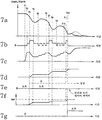
제7a 내지 7g도는 (제5도에 도시된 플로우챠트에 관련된) ABS의 작동을 도시하는 플로우차트.7A-7G are flowcharts illustrating the operation of ABS (relative to the flowchart shown in FIG. 5).
제8도는 제1도에 도시된 ABS용으로 사용 가능한 다른 유압 작동기를 도시하는 개략 유압 시스템 선도.8 is a schematic hydraulic system diagram showing another hydraulic actuator usable for the ABS shown in FIG.
제9도는 제3도에 도시된 제어 회로에 채택된 마이크로컴퓨터에 의해 수행되는 서브 루틴(제어 절차)의 다른 예를 도시하는 플로우차트.FIG. 9 is a flowchart showing another example of a subroutine (control procedure) performed by a microcomputer adopted in the control circuit shown in FIG.
제10a 내지 10g도는 (제9도에 도시된 플로우차트에 관련된) ABS의 작동을 도시하는 플로우차트.10A-10G are flowcharts illustrating the operation of ABS (relative to the flowchart shown in FIG. 9).
* 도면의 주요부분에 대한 부호의 설명* Explanation of symbols for main parts of the drawings
1FL, 1FR, 1RL, 1RR : 차륜 2 : 엔진1FL, 1FR, 1RL, 1RR: Wheel 2: Engine
3 : 변속기3: transmission
6FL, 6FR, 6RL, 6RR : 차륜 브레이크 실린더6FL, 6FR, 6RL, 6RR: Wheel Brake Cylinder
7FL, 7FR, 7RL, 7RR : 차륜 속도 센서7FL, 7FR, 7RL, 7RR: Wheel Speed Sensor
8 : 브레이크 페달 9 : 마스터 실린더8: brake pedal 9: master cylinder
10F, 10R : 유압 작동기 12FL, 12FR : 솔레노이드 밸브10F, 10R: Hydraulic Actuator 12FL, 12FR: Solenoid Valve
15 : 모터 17F, 17R : 저장 탱크15:
21 : 제어기 31 : 작동기 릴레이21 controller 31 actuator relay
[발명의 목적][Purpose of invention]
[발명이 속하는 기술분야 및 그 분야의 종래기술][Technical field to which the invention belongs and the prior art in that field]
본 발명은 제동시에 차륜 로크를 방지하여서 스키딩(skidding)을 방지하는 로크 방지 브레이크 시스템(anti-lock brake system; ABS)에 관한 것으로, 특히 시스템 내에 채택된 복귀 펌프(return pump)를 회전시키도록 된 전기 모터의 고장시에 자체 진단(self-diagnosis)을 할 수 있는 로크 방지 브레이크 제어 시스템에 관한 것이다.FIELD OF THE INVENTION The present invention relates to an anti-lock brake system (ABS) that prevents skidding by preventing wheel lock during braking, and in particular is intended to rotate a return pump employed in the system. An anti-lock brake control system capable of self-diagnosis in case of failure of an electric motor.
근년에, 스키딩을 방지하여 최대 유효 제동력을 제공하도록 설계 된 다양한 로크 방지 브레이크 제어 시스템이 제안되고 개발되었다. 로크 방지 브레이크 시스템을 갖는 최근 모델의 자동차에서, 로크 방지 브레이크 시스템의 유압 작동기 내에 유동 가능하게 배치된 소위 ABS 펌프라 종종 불리는 복귀 펌프의 전기 모터의 와이어 커넥터가 느슨해지는 것과 같은 모터 와이어 고장시 자체 진단을 수행하도록, 로크 방지 브레이크 시스템 내에 자체 진단 시스템이 종종 합체된다. 공지된 바와 같이, 통상의 로크 방지 브레이크 시스템은 저장 탱크 및 복귀 펌프를 사용한다. 복귀 펌프는 스키드(skid) 제어를 위해 선택된 어떠한 차륜에 대한 차륜 브레이크 실린더 내의 유압을 감소시키도록 되어 있다. 저장 탱크는, 차륜 브레이크 실린더 내의 압력 감소의 결과로서 실린더로부터 배출된 브레이크 유체를 임시적으로 축적하도록, 복귀 펌프의 유입 포트와 차륜 브레이크 실린더 모두에 연결된 브레이크 라인 내에 유동 가능하게 배치된다. ABS에 포함된 복귀 펌프는 통상적으로 전기 모터에 의해 구동된다. 모터 구동식 복귀 펌프의 모터 와이어 커넥터가 분리되거나 모터 와이어 자체가 ABS의 작동 중에 소손된 경우에, 스키드 방지 제어가 갑자기(0.1 초 미만의 짧은 순간 동안에) 중단된다. 따라서, 복귀 펌프에 관련된 모터가 비정상인 때에 자체 진단을 수행하는 것이 필요하다. 복귀 펌프의 모터의 비정상에 대한 자체 진단을 수행하는 자체 진단 시스템을 갖는 종래의 로크 방지 브레이크 시스템에서, 로크 방지 브레이크 시스템은 자체 진단 시스템이 ABS 작동 중에 ABS 펌프의 전기 모터의 비정상임을 결정한 즉시, 시스템 작동을 중단시키고 브레이크의 통상 작용(normal application)을 허용하도록 설계된다. 알 수 있는 바와 같이, 시스템이 ABS 펌프의 모터가 스키드 제어 중에 고장이 있음을 결정하자마자 브레이크의 통상 작용이 재개된다면, 만족스러운 로크 방지 제어 작용이 제공될 수 없고, 따라서 스키드 제어로부터 통상 제동 상태로의 급격한 전이로 인해, 스키딩 저구동력 차륜(skidding less-traction wheel)의 스키드가 만족스럽게 수렴(convergence)될 수 없다.In recent years, various antilock brake control systems have been proposed and developed that are designed to prevent skidding to provide maximum effective braking force. In recent models of automobiles with an anti-lock brake system, self-diagnosis in the event of a motor wire failure, such as loosening of the wire connector of the electric motor of a return pump, often called ABS pump, which is flowably disposed within the hydraulic actuator of the anti-lock brake system. Self-diagnosis system is often incorporated into the lock prevention brake system to accomplish this. As is known, conventional lock prevention brake systems use storage tanks and return pumps. The return pump is adapted to reduce the hydraulic pressure in the wheel brake cylinder for any wheel selected for skid control. The storage tank is movably disposed in a brake line connected to both the inlet port of the return pump and the wheel brake cylinder to temporarily accumulate brake fluid discharged from the cylinder as a result of the pressure reduction in the wheel brake cylinder. The return pump included in the ABS is typically driven by an electric motor. When the motor wire connector of the motor driven return pump is disconnected or the motor wire itself is burned out during the operation of ABS, the skid protection control is abruptly interrupted (for a short moment of less than 0.1 second). Therefore, it is necessary to perform self-diagnosis when the motor related to the return pump is abnormal. In a conventional anti-lock brake system having a self-diagnosis system for performing self-diagnosis on the abnormality of the motor of the return pump, the anti-lock brake system immediately determines that the self-diagnosis system is abnormal of the electric motor of the ABS pump during ABS operation. It is designed to interrupt operation and allow normal application of the brakes. As can be seen, if the normal operation of the brake is resumed as soon as the system determines that the motor of the ABS pump has failed during skid control, a satisfactory lock prevention control action cannot be provided and therefore from the skid control to the normal braking state. Due to the sharp transition of, skids of skidding less-traction wheels cannot be converged satisfactorily.
[발명 이 이루고자하는기술적과제][Technical task to be achieved by the invention]
따라서, 본 발명의 목적은 전술한 종래 기술의 결점을 방지하는 자동차용 로크 방지 브레이크 제어 시스템을 제공하기 위한 것이다.It is therefore an object of the present invention to provide an anti-lock brake control system for a vehicle which avoids the above-mentioned drawbacks of the prior art.
본 발명의 다른 목적은, 로크 방지 브레이크 제어 시스템 내에 채택된 복귀펌프(또는 ABS 펌프)의 전기 모터의 모터 고장시에도(예컨대, 느슨해진 모터 와이어 커넥터, 소손된 모터 와이어, 파손된 모터 코일, 단락된 모터 회로 등) 적당한 스키드 제어를 제공하는, 자체 진단 시스템을 갖는 자동차용 로크 방지 브레이크 제어 시스템을 제공하기 위한 것이다.Another object of the present invention is to provide a motor failure of an electric motor of a return pump (or ABS pump) employed in a lock prevention brake control system (e.g., loose motor wire connector, burnt out motor wire, broken motor coil, short circuit). Motor circuit, etc.) to provide a lock prevention brake control system for a vehicle having a self-diagnosis system.
[발명의 구성 및작용][Configuration and Action of the Invention]
본 발명의 상기 및 다른 목적을 성취하기 위하여, 자동차용 로크 방지 브레이크 제어 시스템은 관련 차륜에서 스키드가 개시될 때 스키드 제어에 따라 제어 가능한 관련 차륜에서의 제동 동작을 제공하도록 어느 하나의 차륜에 관련된 차륜 브레이크 실린더와, 복귀 라인을 거쳐 차륜 브레이크 실린더로부터 배출된 브레이크 유체를 임시 저장하도록 제공된 적어도 하나의 저장 탱크와, 전기 모터에 의해 구동되고 저장 탱크 내에 저장된 브레이크 유체를 주 브레이크 유체 라인 쪽으로 배출하도록 제공된 복귀 펌프를 구비하고 차륜 브레이크 실린더에의 브레이크 유체의 급배를 위해 차륜 브레이크 실린더에 유체 연결되도록 되어 있는 유압 작동 유니트와, 차륜의 차륜 속도를 검출하고 차륜 속도를 표시하는 신호를 발생하도록 제공된 차륜 속도 센서와, 차륜 속도 센서로부터의 신호에 응답하여 유압 작동 유니트의 스키드 제어를 실행하는 제어기와, 전기 모터의 고장 진단을 행하는 진단 시스템과, 진단 시스템이 전기 모터 고장을 판별할 때 저장 탱크에 저장된 브레이크 유체의 양을 감시하는 감시 장치를 포함하며, 제어기는 감시 장치에 의해 감시된 브레이크 유체의 양이 소정치에 도달하면 유압 작동 유니트의 스키드 제어를 종료한다. 양호하게는, 유압 작동 유니트는 전륜 브레이크 실린더에 유체 연결되고 제1 복귀 라인을 거쳐서 전륜 브레이크 실린더로부터 배출된 브레이크 유체를 임시 저장하는 제1 저장 탱크를 구비한 제1 유압 작동기와, 전기 모터에 의해 구동되고, 제1 저장 탱크 내에 저장된 브레이크 유체를 제1 주 브레이크 유체 라인으로 배출하도록 된 공통 복귀 펌프와, 후륜 브레이크 실린더에 유체 연결되고 후륜 브레이크 실린더로부터 제1 복귀 라인 및 공통 복귀 펌프와는 분리된 제2 복귀 라인을 거쳐 배출된 브레이크 유체를 임시 저장하고 제2 저장 탱크에 저장된 브레이크 유체를 제1 주 브레이크 유체 라인과는 분리된 제2 주 브레이크 유체 라인을 향해 배출하도록 된 제2 저장탱크를 포함할 수 있으며, 감시 장치는 제1 저장 탱크에 저장된 브레이크 유체의 양과 진단 시스템이 전기 모터가 고장임을 판별할 때 개별 데이타로서 제2 저장 탱크에 저장된 브레이크 유체의 양을 감시하도록 되어 있고, 제어기는 제1 저장 탱크 내에 저장된 브레이크 유체의 양이 제1 소정치에 도달할 때 제1 유압 작동기의 스키드 제어를 종료하고, 제2 저장 탱크 내에 저장된 브레이크 유체의 양이 제2 소정치에 도달할 때 제2 유압 작동기의 스키드 제어를 종료한다.In order to achieve the above and other objects of the present invention, an anti-lock brake control system for a vehicle is provided for a wheel associated with one of the wheels to provide a braking action in the associated wheel which is controllable according to the skid control when the skid is started on the associated wheel. A brake cylinder, at least one storage tank provided for temporarily storing brake fluid discharged from the wheel brake cylinder via the return line, and a return provided to discharge the brake fluid driven by the electric motor and stored in the storage tank toward the main brake fluid line A wheel speed sensor provided with a pump and adapted to be fluidly connected to the wheel brake cylinder for supplying brake fluid to the wheel brake cylinder, and a wheel speed sensor provided to detect a wheel speed of the wheel and generate a signal indicating the wheel speed A controller for performing skid control of the hydraulic actuating unit in response to a signal from the wheel speed sensor, a diagnostic system for diagnosing the failure of the electric motor, and a brake fluid stored in the storage tank when the diagnostic system determines the electric motor failure. And a monitoring device for monitoring the amount, wherein the controller terminates the skid control of the hydraulically actuated unit when the amount of brake fluid monitored by the monitoring device reaches a predetermined value. Preferably, the hydraulic actuating unit comprises a first hydraulic actuator having a first storage tank fluidly connected to the front wheel brake cylinder and via the first return line for temporarily storing brake fluid discharged from the front wheel brake cylinder, by means of an electric motor; A common return pump driven to discharge the brake fluid stored in the first storage tank to the first main brake fluid line, and fluidly connected to the rear brake cylinder and separated from the first return line and the common return pump from the rear brake cylinder. And a second storage tank configured to temporarily store brake fluid discharged through the second return line and to discharge the brake fluid stored in the second storage tank toward a second main brake fluid line separated from the first main brake fluid line. Monitoring device may be used to monitor the amount and volume of brake fluid stored in the first storage tank. The system is arranged to monitor the amount of brake fluid stored in the second storage tank as individual data when determining that the electric motor has failed, and the controller is configured when the amount of brake fluid stored in the first storage tank reaches a first predetermined value. End skid control of the first hydraulic actuator and end skid control of the second hydraulic actuator when the amount of brake fluid stored in the second storage tank reaches the second predetermined value.
감시 장치는 제1 유압 작동기의 스키드 제어 중에 압력 감소 모드의 시간 간격의 적분치를 계수하여 제1 저장 탱크에 저장된 브레이크 유체의 양을 평가하고, 진단 시스템이 전기 모터가 고장임을 판별할 때 제2 유압 작동기의 스키드 제어 중에 압력 감소 모드의 시간 간격의 적분치를 계수함으로써 제2 저장 탱크 내에 저장된 브레이크 유체의 양을 평가하도록 구성될 수 있다. 다르게는, 감시 장치는 제1 저장 탱크에 유입하는 브레이크 유체의 체적 유량과 제2 저장 탱크로 유입하는 브레이크 유체의 체적 유량을 측정하고, 진단 시스템이 전기 모터가 고장임을 판별할때 제1 및 제2 저장 탱크에서 측정한 체적 유량을 개별적으로 적분함으로써 제1 저장 탱크에 저장된 브레이크 유체의 양과 제2 저장 탱크에 저장된 브레이크 유체의 양을 평가하도록 구성될 수 있다. 양호하게는, 감시 장치는 진단 시스템이 전기 모터가 고장임을 판별할 때 제1 및 제2 저장 탱크 각각에 저장된 브레이크 유체의 양을 직접 검출하도록 구성될 수 있다.The monitoring device evaluates the amount of brake fluid stored in the first storage tank by counting the integral of the time intervals in the pressure reduction mode during skid control of the first hydraulic actuator, and when the diagnostic system determines that the electric motor has failed, the second hydraulic pressure It may be configured to evaluate the amount of brake fluid stored in the second storage tank by counting the integral of the time intervals of the pressure reduction mode during skid control of the actuator. Alternatively, the monitoring device measures the volume flow rate of the brake fluid entering the first storage tank and the volume flow rate of the brake fluid entering the second storage tank, and when the diagnostic system determines that the electric motor has failed, The volumetric flow rate measured in the two storage tanks may be individually integrated to evaluate the amount of brake fluid stored in the first storage tank and the amount of brake fluid stored in the second storage tank. Preferably, the monitoring device may be configured to directly detect the amount of brake fluid stored in each of the first and second storage tanks when the diagnostic system determines that the electric motor has failed.
본 발명의 다른 태양에 따르면, 자동차용 로크 방지 브레이크 제어 시스템은 관련 차륜에서 스키드가 개시될 때 스키드 제어에 따라 제어 가능한 관련 차륜에서의 제동 동작을 제공하도록 어느 하나의 차륜에 관련된 다수의 차륜 브레이크 실린더와, 전륜 브레이크 실린더에의 브레이크 유체의 급배를 하도록 탠덤 마스터 실린더의 제1 섹션에 관련된, 전륜 브레이크 실린더에 유체 연결되도록 되어 있으며, 전륜 브레이크 실린더로부터 제1 복귀 라인 및 전기 모터에 의해 구동되는 공통 복귀펌프를 거쳐 배출된 브레이크 유체를 임시 저장하고 제1 저장 탱크에 저장된 브레이크 유체를 제1 주 브레이크 유체 라인을 향해 배출하도록 된 제1 저장 탱크를 구비한 제1 유압 작동기와, 후륜 브레이크 실린더에의 브레이크 유체의 급배를 하도록 탠덤 마스터 실린더의 제2 섹션에 관련된 후륜 브레이크 실린더에 유체 연결되도록 되어 있으며, 후륜 브레이크 실린더로부터 제2 복귀 라인 및 공통 복귀 펌프를 거쳐 배출된 브레이크 유체를 임시 저장하고 제2 저장 탱크에 저장된 브레이크 유체를 제1 주 브레이크 유체 라인과는 별도의 제2 주 브레이크 유체 라인을 향해 배출하도록 된 제2 저장 탱크를 구비한 제2 유압 작동기와, 차륜의 차륜 속도를 검출하고 차륜 속도를 표시하는 신호를 발생시키도록 제공된 차륜 속도 센서와, 차륜 속도 센서로부터의 신호에 응답하여 제1 및 제2 유압 작동기의 스키드 제어를 실행하는 제어기와, 전기 모터의 고장시에 진단을 하기 위한 진단 시스템과, 진단 시스템이 전기 모터가 고장임을 판별할 때 제1 저장 탱크에 저장된 브레이크 유체의 양과 제2 저장 탱크에 저장된 브레이크 유체의 양을 개별적으로 감시하는 감시 장치를 포함하며, 제어기는 제1 저장 탱크에 저장된 브레이크 유체의 양이 제1 소정치에 도달할때 제1 유압 작동기의 스키드 제어를 종료하고 제2 저장 탱크에 저장된 브레이크 유체의 양이 제2 소정치에 도달할 때 제2 유압 작동기의 스키드 제어를 종료한다. 이러한 경우에, 양호하게는, 감시 장치는 제1 유압 작동기의 스키드 제어 중에 압력 감소 모드의 시간 간격의 적분치를 계수하여 제1 저장 탱크에 저장된 브레이크 유체의 양을 평가하고, 진단 시스템이 전기 모터가 고장임을 판별할 때 제2 유압 작동기의 스키드 제어 중에 압력 감소 모드의 시간 간격의 적분치를 졔수함으로써 제2 저장 탱크 내에 저장된 브레이크 유체의 양을 평가하도록 구성될 수 있다. 다르게는, 감시 장치는 제1 저장 탱크에 유입하는 브레이크 유체의 체적 유량과 제2 저장탱크로 유입하는 브레이크 유체의 체적 유량을 측정하고, 진단 시스템이 전기 모터가 고장임을 판별할 때 제1 및 제2 저장 탱크에서 측정한 체적 유량을 개별적으로 적분함으로써 제1 저장 탱크에 저장된 브레이크 유체의 양과 제2 저장 탱크에 저장된 브레이크 유체의 양을 평가하도록 구성될 수 있다. 다른 것에 있어서, 감시 장치는 진단 시스템이 전기 모터가 고장임을 판별할 때 제1 및 제2 저장 탱크 각각에 저장된 브레이크 유체의 양을 직접 검출하도록 구성될 수 있다.According to another aspect of the present invention, an anti-lock brake control system for a vehicle includes a plurality of wheel brake cylinders associated with one of the wheels to provide a braking action on the associated wheels that are controllable in accordance with the skid control when the skid is started on the associated wheels. And a common return driven by the first return line and the electric motor from the front wheel brake cylinder, the fluid return being connected to the front wheel brake cylinder, which is related to the first section of the tandem master cylinder, to supply the brake fluid to the front wheel brake cylinder. A first hydraulic actuator having a first storage tank configured to temporarily store brake fluid discharged through the pump and to discharge the brake fluid stored in the first storage tank toward the first main brake fluid line, and brake to the rear brake cylinder Tandem Master Seal to Drain Fluid The brake fluid discharged from the rear brake cylinder via the second return line and the common return pump, and temporarily storing the brake fluid stored in the second storage tank. A second hydraulic actuator having a second storage tank adapted to discharge toward a second main brake fluid line separate from the main brake fluid line and provided to detect a wheel speed of the wheel and generate a signal indicative of the wheel speed A wheel speed sensor, a controller that performs skid control of the first and second hydraulic actuators in response to a signal from the wheel speed sensor, a diagnostic system for diagnosing a failure in the failure of the electric motor, and the diagnostic system includes: The amount of brake fluid stored in the first storage tank and the bray stored in the second storage tank when determining the fault A monitoring device for individually monitoring the amount of fluid, wherein the controller terminates skid control of the first hydraulic actuator when the amount of brake fluid stored in the first storage tank reaches a first predetermined value and returns to the second storage tank. The skid control of the second hydraulic actuator is terminated when the amount of stored brake fluid reaches the second predetermined value. In such a case, preferably, the monitoring device estimates the amount of brake fluid stored in the first storage tank by counting the integral of the time intervals of the pressure reduction mode during the skid control of the first hydraulic actuator, and the diagnostic system is configured to It may be configured to evaluate the amount of brake fluid stored in the second storage tank by taking the integral of the time interval of the pressure reduction mode during skid control of the second hydraulic actuator when determining that there is a failure. Alternatively, the monitoring device measures the volume flow rate of the brake fluid entering the first storage tank and the volume flow rate of the brake fluid flowing into the second storage tank, and when the diagnostic system determines that the electric motor has failed, The volumetric flow rate measured in the two storage tanks may be individually integrated to evaluate the amount of brake fluid stored in the first storage tank and the amount of brake fluid stored in the second storage tank. In another, the monitoring device may be configured to directly detect the amount of brake fluid stored in each of the first and second storage tanks when the diagnostic system determines that the electric motor has failed.
본 발명의 또 다른 태양에 따르면, 모터 고장 진단 시스템과 조합되며, 전기 모터와 구동 연결된 공통 복귀 펌프와, 제1 복귀 라인을 거쳐 연결되고 전륜에 관련된 제1 저장 탱크와, 제1 복귀 라인과는 별개의 제2 복귀 라인에 연결되고 후륜에 관련된 제2 저장 탱크를 구비한 로크 방지 브레이크 제어 시스템을 구비한 자동차의 스키드 제어 방법에 있어서, 차량에 탑재된 전후륜의 차륜 속도를 검출하고 상기 차륜 속도를 표시하는 차륜 속도 신호를 발생하는 단계와, 상기 각 차륜 속도의 슬립율과 상기 차륜 속도 신호에 응답한 상기 차륜 각각의 유도치를 연산하는 단계와, 상기 슬립율을 소정 목표 슬립율과 비교하여 제1 비교치를 생성하는 단계와, 상기 유도치를 소정 가속 한계치와 소정 감속 한계치와 비교하여 제2 비교치를 생성하는 단계와, 상기 제1 및 제2 비교치에 응답하여 상기 차륜 속도의 각각의 스키드 제어를 수행하는 단계와, 상기 제1 저장 탱크에 저장된 브레이크 유체의 양이 상기 제1 저장 탱크의 총 용량에 달하였는지를 판별하는 단계와, 상기 제1 저장 탱크에 저장된 브레이크 유체의 양이 상기 제1 저장 탱크의 총 용량에 도달하는 필요 조건과 상기 제2 저장 탱크에 저장된 브레이크 유체의 양이 상기 제2 저장 탱크의 총 용량에 도달하는 필요 조건 중 어느 하나를 만족할 때 상기 전륜의 스키드 제어와 상기 후륜의 스키드 제어를 동시에 종료하는 단계를 포함한다.According to yet another aspect of the present invention, a common return pump, coupled to a motor failure diagnosis system, connected to an electric motor, a first storage tank connected via a first return line and associated with a front wheel, and a first return line A skid control method of an automobile having a lock preventing brake control system having a second storage tank associated with a rear wheel and connected to a separate second return line, the method comprising: detecting the wheel speed of the front and rear wheels mounted on the vehicle and Generating a wheel speed signal indicating a; calculating a slip rate of each wheel speed and an induction value of each wheel in response to the wheel speed signal; and comparing the slip rate with a predetermined target slip rate. Generating a first comparison value, comparing the induction value with a predetermined acceleration limit value and a predetermined deceleration limit value to generate a second comparison value; Performing respective skid control of the wheel speed in response to the first and second comparison values, determining whether the amount of brake fluid stored in the first storage tank has reached the total capacity of the first storage tank; The requirement that the amount of brake fluid stored in the first storage tank reach the total capacity of the first storage tank and that the amount of brake fluid stored in the second storage tank reach the total capacity of the second storage tank And ending skid control of the front wheel and skid control of the rear wheel simultaneously when any one of the necessary conditions is satisfied.
본 발명의 또 다른 태양에 따르면, 모터 고장 진단 시스템과 조합되며, 전기 모터와 구동 연결된 공통 복귀 펌프와, 제1 복궈 라인을 거쳐 연결되고 전륜에 관련된 제1 저장 탱크와, 제1 복귀 라인과는 별개의 제2 복귀 라인에 연결되고 후륜에 관련된 제2 저장 탱크를 구비한 로크 방지 브레이크 제어 시스템을 구비한 자동차의 스키드 제어 방법에 있어서, 차량에 탑재된 전후륜의 차륜 속도를 검출하고 상기 차륜 속도를 표시하는 차륜 속도 신호를 발생하는 단가와, 상기 각 차륜 속도의 슬립율과 상기 차륜 속도 신호에 응답한 상기 차륜 각각의 유도치를 연산하는 단계와, 상기 슬립율을 소정 목표 슬립율과 비교하여 제1 비교치를 생성하는 단계와, 상기 유도치를 소정 가속 한계치와 소정 감속 한계치와 비교하여 제2 비교치를 생성하는 단계와, 상기 제1 및 제2 비교치에 응답하여 상기 차륜 속도의 각각의 스키드 제어를 수행하는 단계와, 상기 제1 저장 탱크에 저장된 브레이크 유체의 양이 상기 제1 저장 탱크의 총 용량에 달하였는지를 판별하는 단계와, 상기 제1 저장 탱크에 저장된 브레이크 유체의 양이 상기 제1 저장 탱크의 총 용량에 도달하는 필요 조건과는 관계없이 상기 제2 저장 탱크에 저장된 브레이크 유체의 양이 상기 제2 저장 탱크의 총 용량에 도달하는 필요 조건을 만족할 때 상기 전륜의 스키드 제어와 상기 후륜의 스키드 제어를 동시에 종료하는 단계를 포함한다.According to yet another aspect of the present invention, a common return pump, coupled to a motor failure diagnosis system, driven in connection with an electric motor, a first storage tank connected via a first return line and associated with a front wheel, and a first return line A skid control method of an automobile having a lock preventing brake control system having a second storage tank associated with a rear wheel and connected to a separate second return line, the method comprising: detecting the wheel speed of the front and rear wheels mounted on the vehicle and Calculating a unit price for generating a wheel speed signal indicating a value, a slip rate of each wheel speed, and an induction value of each wheel in response to the wheel speed signal, and comparing the slip rate with a predetermined target slip rate; Generating a first comparison value, comparing the induction value with a predetermined acceleration limit value and a predetermined deceleration limit value to generate a second comparison value; Performing respective skid control of the wheel speed in response to the first and second comparison values, determining whether the amount of brake fluid stored in the first storage tank has reached the total capacity of the first storage tank; And the amount of brake fluid stored in the second storage tank is the total capacity of the second storage tank regardless of the requirement that the amount of brake fluid stored in the first storage tank reaches the total capacity of the first storage tank. And ending skid control of the front wheel and skid control of the rear wheel at the same time when the necessary condition of reaching is reached.
제1도를 참조하면, 종동륜인 좌우측 전륜(1FL, 1FR) 및 구동륜인 좌우측 후륜(1RL, 1RR)을 갖는 후륜 구동 차량의 경우에서의, 본 발명의 자동차용 로크 방지 브레이크 제어 시스템이 예시되어 있다. 엔진(2)의 출력은 변속기(3), 프로펠러 샤프트(4) 및 차동 장치(5)를 통해 후방 액슬 샤프트를 거쳐 후륜(1RL, 1RR)으로 전달된다. 유압 제동 작용을 위하여, 4개의 차륜 브레이크 실린더(6FL 내지 6RR)가 각각의 차륜(1FL 내지 1RR)에 설치된다. 좌우 전륜 속도 센서(7FL, 7FR)는 좌우 전륜 속도 표시 신호(VFL, VFR)를 사인파의 교류(AC) 형태로 발생시키도록 각각의 전륜(1FL, 1FR)에 위치된다. 차륜의 회전 속도가 높을수록 AC의 주파수도 높아진다. 동일한 방식으로, 좌우 후륜 속도 센서(7RL, 7RR)는 좌우 후륜 속도 표시 신호(VRL, VRR)를 교류(또는 사인파 신호) 형태로 발생시키도록 각각의 후륜(1RL, 1RR)에 위치된다. 초기 모델의 후륜 구동 차량은 통상적으로 제1도에서 알 수 있는 이중 브레이크 시스템(dual-brake system)을 사용한다. 이중 브레이크 시스템은 (도시되지 않은) 2개의 피스톤이 탠덤(tandem) 내에 설치된 마스터 실린더(9)를 갖는다. 종래 방식으로, 이중 브레이크 시스템에서, 2개의 별도의 유압 섹션이 독립적으로 기능한다. 탠덤 마스터 실린더(9)의 제1 유압 챔버(예컨대, 전방 섹션) 내의 마스터 실린더 압력은 전륜측 유압 작동기(10F)(전륜 브레이크 실린더용 유압 작동 유니트)를 통해 2개의 전륜 브레이크 실린더(6FL, 6FR)로 공급되는 반면에, 탠덤 마스터 실린더(9)의 제2 유압 챔버(예컨대, 후방 섹션) 내의 마스터 실린더 압력은 후륜측 유압작동기(10R)(후륜 브레이크 실린더용 유압 작동 유니트)를 통해 2개의 후륜 브레이크 실린더(6RL, 6RR)로 공급된다. 마스터 실린더 압력은 브레이크 페달(8)의 누름(또는 밟음) 크기에 응답하여 증가한다. 제2도에서 명백히 알 수 있는 바와 같이, 전륜측 유압 작동기(10F)는 (브레이크 유체 공급 라인으로서 주로 역할하는) 주 브레이크 유체 라인(11F)을 통해 마스터 실린더(9)의 전방 섹션에 유동 가능하게 연결된다. 통상적인 3포트 3위치 전자기 솔레노이드 밸브(12FL)가 좌측 전륜 브레이크 실린더(6FL)와 전방 브레이크 라인(11F) 사이에 유동 가능하게 배치된다. 동일한 방식으로, 솔레노이드 밸브(12FR)가 관련 우측 전륜 브레이크 실린더(6FR)와 전방 브레이크 라인(11F) 사이에 유동 가능하게 배치된다. 각각의 3포트 3위치 전자기 솔레노이드 밸브에 관해서는, 도면 부호 12i, 12s, 12r은 각각 유입 포트, 공급 포트 및 복귀 포트를 나타낸다. 유입 포트(12i)는 전방 브레이크 라인(11F)에 연결되고, 공급 포트(12s)는 관련 차륜 브레이크 실린더에 연결되며, 복귀 포트(12r)는 도면 부호 13FL 또는 13FR로 나타낸 고정형 오리피스를 통해 복귀 라인(14r)에 연결되고 나서 [복귀 라인(14r)에 마련된] 유입 첵 밸브(14F)를 거쳐 복귀 펌프 조립체(16)의 제1펌프 섹션(16F)의 흡입 포트에 연결된다. 전륜측 저장 탱크(17F)는 각각의 고정형오리피스(13FL, 13FR)의 하류측 및 유입 첵 밸브(14F)의 상류측에서 복귀 라인(14r)에 연결된다. 제2제2도에서 알 수 있는 바와 같이, 저장 탱크(17F)는 적어도 복귀 스프링(17a), 피스톤(17b) 및 원통형 하우징(17c)으로 구성된다. 저장 탱크(17F)의 피스톤(17b)은 복귀 스프링(17a)에 의해 최초 위치(스프링 편의 위치)를 향해 편의된다. 저장 탱크(17F)는 마스터 실린더 압력이 소정 압력 레벨로 강하될 때 스프링(17a)의 편의력에 의해 저장 탱크 내의 브레이크 유체를 복귀 라인(14r)의 일부, 첵 밸브(14c) 및 바이패스 라인(14b)을 통해 브레이크 라인(11F)으로 공급하도록 설계된다. 즉, 저장 탱크(17F)는 브레이크 페달(8)이 전혀 눌러지지 않고 브레이크가 완전히 해제될 때 저장 탱크(17F) 내에 임시 저장되어 보급되는 브레이크 유체가 브레이크 라인(11F)을 향해 저장 탱크(17F) 외부로 완전히 배출되도록 설계된다. 각각의 솔레노이드 밸브(12FL, 12FR)는 후술되는 로크 방지 브레이크 제어기(21)에 전자적으로 접속된다. 각각의 3포트 3위치 솔레노이드 밸브는 전자기 솔레노이드(SL)를 가지며, 제어기(21)에 의해 인가되는 솔레노이드 구동 전류[또는 여자 전류(exciting current)]의 크기에 응답하여 작동된다. 유입 포트(12i)와 공급 포트(12s) 사이에는 유체 연통이 이루어지며, 복귀 포트(12r)는 솔레노이드(SL)에 인가되는 여자 전류(Ii)(i = FL, FR, RL, RR)가 0의 전류치(zero current value)를 나타낼 때 공급 포트(12s)와의 연통이 차단된다. 이러한 것은 솔레노이드 밸브는 0의 전류 신호가 있을때 압력 증가 위치에서 유지된다는 것을 의미한다. 솔레노이드에 인가된 여자 전류가 소정의 중간 전류치일 때, 3개의 포트(12i, 12s, 12r)는 서로로부터 모두 차단된다. 이는 소정의 중간 전류 레벨의 여자 전류가 인가되는 경우에 솔레노이드 밸브가 압력 유지 위치에서 유지된다는 것을 의미한다. 솔레노이드에 인가된 여자 전류가 소정의 높은 전류치일 때, 공급 포트(12s)와 복귀 포트(12r) 사이의 유체 연통이 이루어지고 유입 포트(12i)는 차단된다. 이는 소정의 높은 전류치의 여자 전류가 인가되는 경우에 솔레노이드 밸브가 압력 감소 위치에서 유지된다는 것을 의미한다. 제1펌프 섹션(16f)은 복귀 라인(14r) 내의 브레이크 유체를 유출 첵 밸브(18F) 및 댐퍼(19F)를 통해 전방 브레이크 라인(11F)으로 복귀시키는 역할을 한다. 댐퍼(19F)는 복귀 펌프로부터 토출된 브레이크 유체의 토출 압력의 변동을 완화 또는 감쇠시키는 감쇠 챔버를 갖는다. 설정 압력 스프링을 갖는 일방 첵 밸브(20FL)는 바이패스 라인 내에 유동 가능하게 배치되며, 바이패스 라인은 유입 포트(12i) 및 공급 포트 (12s)에 연결되도록 하는 방식으로 관련 솔레노이드 밸브(12FL)와 평행하게 배열된다. 마찬가지로, 설정 압력 스프링을 갖는 일방 첵 밸브(20FR)는 관련 솔레노이드 밸브(12FR)와 평행하게 배열된 바이패스 라인 내에 유동 가능하게 배치된다. 각각의 첵 밸브(20FL 또는 20FR)는 공급 포트 내의 유체 압력이 설정 압력 스프링에 의해 결정된 소정 압력 레벨을 초과할 때 공급 포트(12s)로부터 유입 포트(12i)로 유체가 유동하도록 한다. 후륜측 유압 작동기(10R)의 구성은 전술된 전륜측 유압 작동기(10F)의 구성과 유사하다. 또한, 제2도에서 알 수 있는 바와 같이, [전륜측 유압 작동기(10F)를 갖는] 좌측 유압 회로 및 [후륜측 유압 작동기(10R)]를 갖는] 우측 유압 회로는 서로 대칭이다. 따라서, 후륜측 작동기(10R)의 구성은 자동적으로 설명되는 것으로 여겨지므로 작동기(10R)의 상세한 설명은 생략하기로 한다. 전륜측 유압 작동기(10F)와 후륜측 유압 작동기(10R)를 비교할 때, 도면 부호 12RL 및 12RR은 후방 좌측 3포트 3위치 솔레노이드 밸브 및 후방 우측 3포트 3위치 솔레노이드 밸브를 나타내고, 도면 부호 13RL 및 13RR은 고정형 오리피스를 나타내며, 도면 부호 14R 및 18R은 유입 첵 밸브 및 유출 첵 밸브를 나타내고, 도면 부호 16R은 복귀 펌프 조립체(16)의 제2 펌프 섹션을 나타내며, 도면 부호 17R은 후륜측 저장 탱크를 나타내고, 도면 부호 19R은 감쇠 챔버를 갖는 댐퍼를 나타내며, 도면 부호 20RL 및20RR은 설정 압력 스프링을 갖는 일방 첵 밸브를 각각 나타낸다. 전술된 복귀 펌프 조립체(16)는 제1 펌프 섹션(16F) 및 제2 펌프 섹션(16R) 모두를 구동하기 위한 전기 모터(15)를 포함한다. 도시된 실시예에서, 플런저 펌프가 사용되지만, 다른 종류의 유압 펌프가 ABS의 복귀 펌프로서 사용될 수 있다. 제1도로 돌아가면, 브레이크 램프 스위치(또는 정지 램프 스위치)(8a)가 브레이크 페달(8) 부근에 또한 마련된다. 종래의 방식으로, 브레이크 램프 스위치(8a)는 브레이크 페달의 누름에 응답하여 작동된다. 브레이크가 해제된 때 브레이크 램프 스위치(8a)의 전기 접점이 개방된 상태로 남아 있어 스위치(8a)로부터의 신호는 낮은 신호 레벨(절환된 오프 신호)에서 유지된다. 브레이크 페달이 눌러짐에 따라, 스위치(8a)로부터의 신호는 높은 신호 레벨(절환된 온 스위치)에서 유지된다. 제어기(21)는 브레이크 램프 스위치(8a)로부터 신호를 수신하고, 4개의 차륜 속도 센서(7FL 내지 7RR)로부터 차륜 속도 표시 AC 전압 신호(VFL, VFR, VRL, VRR)를 수신한다.Referring to FIG. 1, the lock prevention brake control system for an automobile of the present invention is illustrated in the case of a rear wheel drive vehicle having left and right front wheels 1FL and 1FR as driven wheels and left and right rear wheels 1RL and 1RR as drive wheels. have. The output of the
이제, 제3도를 참조하면, 제어기(21)는 파형 정형 회로(또는 파형 정형기)(22), 마이크로컴퓨터(23), 솔레노이드 밸브(12FL 내지 12RR)의 각각의 솔레노이드(SL)와 관련된 4개의 솔레노이드 구동 회로(26FL 내지 26RR), 모터 릴레이 감시 회로(또는 모터 전압 검출 회로)(27) 및 경고 표시기(32)를 포함한다. 마이크로컴퓨터(23)는 입력 인터페이스 회로(또는 입력 인터페이스)(23a), 프로세서(23b), 메모리(23c) 및 출력 인터페이스 회로(또는 출력 인터페이스)(23d)로 구성된다. 제3도에서 알 수 있는 바와 같이, 프로세서(23b) 및 메모리(23c)는 정보의 자동 전송 및 수신을 위하여 서로 상호 연결된다. 파형 정형 회로(22)는, 차륜 속도 센서(7FL 내지 7RR)로부터 수신된 AC 전압 신호(VFL, VFR, VRL, VRR)를 배증시키고 배증된 전압 신호를 파형 정형시킴으로써 전압 신호를 직사각형 신호로 변환시키도록, 4개의 차륜 속도 센서(7FL 내지 7 RR)와 입력 인터페이스 회로(23a) 사이에 연결된다. 파형 정형 회로(22)는 아날로그 대 디지탈 변환(간단하게는, A/C 변환)을 수행한다. 입력 인터페이스 회로(23a)는 파형 정형 회로(22)로부터의 4개의 직사각형 신호, 브레이크 램프 스위치(8a)로부터의 신호, 모터 릴레이 감시 회로(27)로부터의 [모터(15)에 인가된 단자 전압에 대응하는] 전압 신호(VM)를 수신한다. 2개의 유압 작동기(10F, 10R)를 위한 전기 모터(15)의 비정상 여부에 대하여 진단하도록 그리고 이후에 상세히 설명되는 제5도에 도시된 하나의 서브 루틴을 수행하거나 제9도에 도시된 다른 서브 루틴을 실행하도록 프로세서(23b)가 마련된다. 예컨대, 프로세서(23b)는 입력 인터페이스 회로(23a)로 입력된 4개의 직사각형 신호를 기초로 하여 좌측 전륜 속도(VWFL), 우측 전륜 속도(VWFR), 좌측 후륜 속도(VWRL) 및 우측 후륜 속도(VWRR)를 연산하며, 또한, 각각의 차륜의 슬립율(SFL, SFR, SRL, SRR)을 구하고 4개의 슬립율(SFL내지 SRR)을 예컨대 15 %인 목표 슬립율(So)과 비교하여 스키드 제어를 위해 선택된 적어도 하나의 차륜(정확하게는, 차륜 브레이크 실린더)에 대한 로크 방지 브레이크 제어를 수행하도록 4개의 연산된 차륜 속도(VWFL, VWFR, VWRL, VWRR)를 기초로 하여 소위 의사 차속(pseudo vehicle speed, VC)을 연산 또는 결정한다, 프로세서(23b)에 의해 실행된 산술 처리(서브 루틴)의 결과를 임시 저장하도록 그리고 필요한 경우에 프로세서(23b)에 임시 저장된 데이타를 전송하도록 메모리(23c)가 마련된다. 출력 인터페이스 회로(23d)는 여러 제어 신호[SD, SM, SA, DSi(i = FL, FR, RL, RR), HSi(i = FL, FR, RL, RR)]를 출력하기 위하여, 프로세서(23b)에 의해 실행된 산술 처리의 결과에 응답한다. 제1 npn 트랜지스터(24)의 베이스(base)는 모터 릴레이(28)가 온으로 된 상태에서 모터(15)에 통전시키기 위하여 모터 릴레이 구동 신호(또는 모터 제어 신호)(SM)를 수신하도록 출력 인터페이스 회로(23d)에 접속된다. 제2 npn 트랜지스터(25)의 베이스는 스키드 제어를 받는 차륜과 관련된 솔레노이드 밸브의 솔레노이드(SL)에 작동기 릴레이가 온으로 된 상태에서 통전시키기 위하여 작동기 릴레이 구동 신호(또는 작동기 제어 신호)(SA)를 수신하도록 출력 인터페이스 회로(23d)에 접속된다. 전방 좌측 솔레노이드 구동 회로(26FL)는 출력 인터페이스 회로(23d)로부터 좌측 전륜 압력 감소 표시 신호(DSFL) 및 좌측 전륜 압력 유지 표시 신호(HSFL)를 수신하여, 2개의 신호(DSFL, HSFL)의 신호 값 각각이 높은 신호 레벨 또는 낮은 신호 레벨에 있는지의 여부에 따라 여자 전류(IFL)를 발생시키도록 한다. 전방 우측 솔레노이드 구동 회로(26FR)는 출력 인터페이스 회로(23d)로부터 우측 전륜 압력 감소 표시 신호(DSFR) 및 우측 전륜 압력 유지 표시 신호(HSFR)를 수신하여, 신호(DSFR, HSFR)의 신호 값 모두에 따라 여자 전류(IFR)를 발생시키도록 한다. 후방 좌측 솔레노이드 구동 회로(26RL)는 출력 인터페이스 회로(23d)로부터 좌측 후륜 압력 감소 표시 신호(DSRL) 및 좌측 후륜 압력 유지 표시 신호(HSRL)를 수신하여, 신호(DSRL, HSRL)의 신호 값 모두에 따라 여자 전류(IRL)를 발생시키도록 한다. 후방 우측 솔레노이드 구동 회로(26RR)는 출력 인터페이스 회로(23d)로부터 우측 후륜 압력 감소 표시 신호(DSRR) 및 우측 후륜 압력 유지 표시 신호(HSRR)를 수신하여, 신호(DSRR, HSRR)의 신호 값 모두에 따라 여자 전류(IRR)를 발생시키도록 한다. 모터 릴레이 감시 회로(전압 검출 회로)(27)는 모터의 단자 전압(VM)을 감시 또는 검출하도록, 모터(15)의 양극 단자와 모터 릴레이(28)의 하나의 전기 접점을 상호 접속하는 전기선에 연결된다. 모터 릴레이(28)의 다른 전기 접점은 자동차 배터리의 양극 단자에 연결된다. 모터 릴레이의 여자 코일(28a)의 일단부는 npn 트랜지스터(24)의 콜렉터(collector)에 연결되고 여자 코일(28a)의 타단부는 점화 스위치(29)를 통해 배터리 양극 단자에 연결된다. 제1 트랜지스터(24)의 에미터(emitter)는 접지된다. 모터 릴레이 구동 신호(SM)가 낮은 신호 레벨에서 유지될 때, 여자 코일(28a)에는 트랜지스터(24)가 오프로 된 상태에서 통전되지 않아서, 모터 릴레이(28)는 오프 상태로 남게 된다. 반대로, 신호(SM)가 높은 신호 레벨로 이동된 때, 여자 코일(28a)에는 트랜지스터(24)가 온으로 된 상태에서 통전되어서 모터 릴레이(28)는 온상태로 된다. 모터 릴레이(28) 및 작동기 릴레이(31) 각각은 통상 상태에서 폐쇄되어 있는 종류의 릴레이(normally-closed type relay)이다. 릴레이(28)의 아마츄어(armature, 28b)가 트랜지스터(24)가 온으로 됨에 따라 작동될 때, 릴레이(28)의 2개의 릴레이 접점은 릴레이 아마츄어(28b)에 의해 폐쇄되어서 배터리 전압이 온 상태가 된 릴레이(28)를 통해 모터의 입력 단자로 인가된다. 모터(15)에 인가된 이러한 단자 전압은 전술된 릴레이 감시 회로(27)에 의해 검출된다. 한편, 각각의 솔레노이드 밸브(12FL 내지 12RR)의 하나의 솔레노이드 단자는 관련 솔레노이드 구동 회로에 접속되는 반면에, 다른 솔레노이드 단자는 솔레노이드의 작동을 위하여 작동기 릴레이(31)의 하나의 릴레이 접점에 접속된다. 릴레이(31)의 다른 릴레이 접점은 배터리 양극 단자에 접속된다. 작동기 릴레이(31)의 여자 코일(31a)의 일단부는 제2 npn 트랜지스터(25)의 콜렉터에 접속되는 반면에, 여자 코일(31a)의 타단부는 점화 스위치(29)를 통해 자동차 배터리(30)의 양극 단자에 접속된다. 트랜지스터(25)의 에미터는 예컨대 차체를 통해 접지된다. 작동기 릴레이 구동 신호(SA)가 낮은 신호 레벨에서 유지될 때, 트랜지스터(25)가 오프로 된 상태에서 여자 코일(31a)은 여자되지 않아서 작동기 릴레이(31)는 절환된 오프 상태로 남게 된다. 역으로, 신호(SA)가 낮은 신호 레벨로부터 높은 신호 레벨로 변화된 때, 여자 코일(31a)은 여자되어서, 온 상태로 된 트랜지스터(25)의 결과로서 릴레이 아마츄어(31b)가 작동된다.Referring now to FIG. 3, the
솔레노이드 구동 회로(26FL, 26FR, 26RL, 26RR) 각각은 다음과 같이 작동한다.Each of the solenoid drive circuits 26FL, 26FR, 26RL, 26RR operates as follows.
입력 인터페이스 회로(23d)로부터 솔레노이드 구동 회로[26i, (i= FL, FR, RL, RR)]로 입력된 압력 감소 표시 신호[DSi(i = FL, FR, RL, RR)] 및 압력 유지 표시 신호[HSi(i = FL, FR, RL, RR)] 모두가 낮은 신호 레벨일 때, 솔레노이드 밸브[12i, (i = FL, FR, RL, RR)]를 가로질러 전류가 흐르지 않아서 솔레노이드(SL)에는 통전되지 않으며, 결국 (작동 중인) 솔레노이드 밸브(12i)와 관련된 차륜 브레이크 실린더는 압력 증가 모드로 작동한다. 솔레노이드 구동 회로(26i)에 인가된 2개의 신호 중 압력 유지 표시 신호(HSi)만이 높은 레벨일 때, 소정의 중간 전류치의 여자 전류(Ii)가 솔레노이드 밸브(12i)의 솔레노이드(SL)에 인가되며, 결국 (압력 유지 위치에서 유지된) 솔레노이드 밸브(12i)와 관련된 차륜 브레이크 실린더는 압력 유지 모드에서 작동한다. 솔레노이드 구동 회로(26i)에 인가된 2개의 신호 중 압력 감소 표시 신호(DSi)만이 높은 레벨일 때, 소정의 높은 전류치의 여자 전류가 솔레노이드 밸브(12i)의 솔레노이드(SL)에 인가되며, 결국 (압력 감소 위치에서 유지된) 솔레노이드 밸브(12i)와 관련된 차륜 브레이크 실린더는 압력 감소 모드에서 작동한다.Pressure reduction indication signal DS i (i = FL, FR, RL, RR) input from solenoid drive circuit 26i, (i = FL, FR, RL, RR) from
이제, 제4도를 참조하면, 전압 검출 회로(모터 릴레이 감시 회로)(27)의 일례가 도시되어 있다. 제4도에 도시된 전압 검출 회로(27)는 다이오드(27a), 3개의 저항기 (R1, R2, R3) 및 쉬미트 트리거 회로(Schmitt trigger circuit, 27b)를 포함한다. 다이오드(27a)의 양극은 모터 릴레이(28)의 릴레이 접점과 모터(15)를 상호 접속하는 접속선에 접속되는 반면에, 다이오드(27b)의 음극은 저항기(R1)를 통해 배터리(30)의 양극 단자(Vcc)에 접속되고, 전압 분할기로서 역할하는 저항기 세트(R2 및 R3)를 통해 접지된다. 2개의 저항기(R2, R3) 사이의 접점은 쉬미트 트리거 회로(27b)의 입력 단자에 접속된다. 쉬미트 트리거 회로(27b)는 인가된 전압이 설정 전압 레벨 이하일 때 낮은 전압 레벨의 전압 신호(VM)를 출력하고, 인가된 전압이 설정 전압 레벨 이상일 때 높은 전압 레벨의 전압 신호(VM)를 출력한다. 쉬미트 트리거 회로(27b)로부터의 전압 신호(VM)는 입력 인터페이스 회로(23a)로 전송된다. 실제로, 쉬미트 트리거 회로(27b)는 릴레이(28)가 온으로 된 상태에서 전기 모터(15)가 정상 작동할 때 높은 전압 레벨의 전압 신호(VM)를 발생시키는 기능을 한다. 즉, 모터(15)의 모터 코일의 저항은 모터 코일의 파손 등의 모터 이상이 없는 경우에 매우 작은 값이며, 따라서 전류가 양극 단자(Vcc)로부터 저항기(R1) 및 다이오드(27a)를 통해 모터 코일을 가로질러 흘러, 모터를 정상적으로 구동하도록 한다. 따라서, 모터가 정상적으로 작동한다면, 각각의 저항기(R2, R3)에 인가된 전압은 거의 0이 되는데, 그 이유는 저항기 세트(전압 분할기)(R2 및 R3)를 향해 흐른 전류가 거의 0이 되기 때문이다. 그러므로, 모터(15)가 어떠한 모터 고장도 없이 정상적으로 작동할 때, 쉬미트 트리거 회로(27b)의 입력 단자에 인가되는 전압은 설정 전압 레벨보다 높은 배터리 전압(Vcc)과 거의 동일하다. 이러한 경우에, 쉬미트 트리거 회로(27b)로부터의 전압 신호(VM)의 레벨은 높다. 반대로, 파손된 모터 코일, 느슨해진 모터 와이어 커넥터, 모터 와이어 소손, 모터 와이어 단락 등과 같이 모터 고장이 있는 경우에, 배터리 양극 단자(또는 전원)로부터의 전류 흐름은 2개의 저항기(R2, R3)를 향해 흐르지만 모터(15)로는 흐르지 않는다. 이러한 경우에, 전류는 양극 단자(Vcc)로부터 저항기(R2, R3)를 통해 접지로 흐르며, 결국 쉬미트 회로(27b)의 입력 단자에 인가된 전압은 2개의 저항기(R2, R3)에 의해 분할된다. 따라서, 쉬미트 회로의 입력 단자에 인가된 전압은 설정 전압 레벨과 비교하여 상당히 낮게 된다. 이러한 경우에, 쉬미트 회로(27b)로부터의 전압 신호(VM)는 낮은 레벨로 유지된다. 게다가, 출력 인터페이스 회로(23d)는 경고 신호(SD)는 경고 표시기(32)로 발생시킨다. 통상 상태에서 경고 신호(SD)는 낮은 채로 유지된다. 출력 인터페이스 회로(23d)는, 모터가 전기 모터(15)의 (느슨해진 모터 와이어 커넥터, 파단된 모터 와이어, 소손된 모터 코일, 단락된 모터 회로 등과 같은) 고장을 일으켰음을 제어기가 후술되는 제5도의 산술 처리의 결과를 기초로 하여 결정한다면, 높은 신호 레벨의 경고 신호(SD)를 발생시킨다. 자동차의 계기판 상에 설치되고 경고 표시기 램프를 포함하는 경고 표시 회로 또는 장치(32)는 논리치 1과 같은 높은 신호 레벨의 경고 신호(SD)에 응답하여 작동되어, 예컨대 경고 표시기 램프를 점멸시키도록 한다. 또한, 경고 표시 회로(32)는 운전자 또는 차량 점유자에게 전기 모터(15)가 고장임을 경고하도록 예컨대 3분의 소정 시간 동안 주기적으로 부저음을 발하는 경고 부저(buzzer)를 포함한다. 제어기(21)에 합체된 마이크로컴퓨터(23)의 프로세서(23b)에 의해 실행되는 산술 처리를 제5도에 도시된 플로우차트에 따라 이하에서 상세히 설명하기로 한다.Referring now to FIG. 4, an example of a voltage detection circuit (motor relay monitoring circuit) 27 is shown. The
제5도에 도시된 산술 처리 또는 서브 루틴은 예컨대 10 msec의 매 소정 간격마다 트리거되는 시간 트리거식 인터럽트 루틴으로서 실행된다.The arithmetic processing or subroutine shown in FIG. 5 is executed as a time triggered interrupt routine that is triggered at every predetermined interval of, for example, 10 msec.
단계 S1에서, 4개의 차륜 속도(VWFL, VWFR, VWRL, VWRR) 데이타가 타이어 외경의 공칭값과 센서(7FL 내지 7RR)로부터의 차륜 속도 표시 신호(VFL, VFR, VRL, VRR)를 기초로 하여 연산된다. 단계 S2에서, 소위 의사 차속(Vc)이 단계 S1에서 연산된 4개의 차륜 속도(VWFL, VWFR, VWRL, VWRR) 데이타 중 최고 차륜 속도(VWH)를 기초로 추정된다. 종종 셀렉트-하이 차륜 속도(select-HIGH wheel speed)라 하는 최고 차륜 속도(VWH)는 의사 차속(Vc)으로서 직접 사용될 수 있다. 다르게는, 셀렉트-하이 차륜 속도(VWH)는 소정의 필터링 프로세스를 통해 추가 처리될 수 있고, 소정의 필터링 프로세스를 통해 처리된 차륜 속도는 각각의 슬립율[Si(i = FL, FR, FLL, RR)]의 계산을 위하여 차속(Vc)으로서 사용될 수 있다. 더욱이, 의사 차속(Vc)은 자동차에 가해지는 종방향 가속도의 적분값을 셀렉트-하이 차륜 속도(VWH)에 더함으로써 연산될 수 있다. 이러한 경우에, 시스템은 차체에 장착된 종방향 가속도 센서를 추가로 요구할 수 있다. 단계 S3에서, 4개의 가감속 지시 데이타(V'WFL, V'WFR, V'WRL, V'WRR)가 각각의 연산된 차륜 속도(VWFL, VWFR, VWRL, VWRR) 데이타를 미분함으로써 연산된다. 가감속 표시 데이타의 부호가 양(+)의 부호이면, 상기 데이타는 양의 가속도(간단하게는, 가속)를 나타낸다. 가감속 표시 데이타의 부호가 음(-)의 부호이면, 상기 데이타는 음의 가속도(간단하게는, 감속)를 나타낸다. 단계 S4에서, 4개의 슬립율 표시 데이타[Si(i = FL, FR, RL, RR)]가 (단계 S2를 통해 결정된) 의사 차속(Vc) 및 각각의 차륜 속도[VWi(i = FL, FR, RL, RR)]를 기초로 하여 이하의 수학식 1로부터 연산된다.In step S1, four wheel speeds (V WFL , V WFR , V WRL , V WRR ) data are nominal values of the tire outer diameter and wheel speed indication signals V FL , V FR , V RL from the sensors 7FL to 7RR. , V RR ). In step S2, the so-called pseudo vehicle speed Vc is estimated based on the highest wheel speed V WH among the four wheel speeds V WFL , V WFR , V WRL , V WRR calculated in step S1. The highest wheel speed V WH , often called select-HIGH wheel speed, can be used directly as the pseudo vehicle speed V c. Alternatively, the select-high wheel speed V WH may be further processed through a predetermined filtering process, and the wheel speed processed through the predetermined filtering process may have a respective slip rate [S i (i = FL, FR, FLL, RR)] can be used as the vehicle speed Vc. Furthermore, the pseudo vehicle speed Vc can be calculated by adding the integral value of the longitudinal acceleration applied to the vehicle to the select-high wheel speed V WH . In such a case, the system may further require a longitudinal acceleration sensor mounted on the vehicle body. In step S3, four acceleration / deceleration instruction data (V ' WFL , V' WFR , V ' WRL , V' WRR ) differentiate each calculated wheel speed (V WFL , V WFR , V WRL , V WRR ) data. By calculating. If the sign of the acceleration / deceleration display data is a positive sign, the data represents a positive acceleration (or simply acceleration). If the sign of the acceleration / deceleration display data is a negative sign, the data indicates a negative acceleration (simply deceleration). In step S4, four slip rate indication data [S i (i = FL, FR, RL, RR)] are added to the pseudo vehicle speed Vc (determined via step S2) and the respective wheel speeds V Wi (i = FL , FR, RL, RR)] is calculated from
[수학식 1][Equation 1]
Si= {(VC - VWi)/Vc} × 100S i = {(VC-V Wi ) / Vc} × 100
단계 S4 이후에 단계 S5로 이행하며, 단계 S5에서 로크 방지 브레이크 제어 (간단히, 스키드 제어)는 각각의 슬립율 표시 데이타(Si)를 (예컨대 15 %인 이상적 슬립율에 대응하는) 소정 목표 슬립율(So)과 비교한 결과와, 각각의 가감속 표시 데이타(V'Wi)를 가속에 대한 소정 한계치(β) 및 감속에 대한 소정 한계치(α)와 비교한 결과를 기초로 하여 실행된다. 한계치(β)는 이하에서 가속 한계치라 하고, 한계치(α)는 이하에서 감속 한계치라 하기로 한다. 실제로, 단계 S5에서 실행되는 스키드 제어는 제6도에 도시된 제어 맵(control map)을 기초로 한다. 브레이크 페달이 전혀 눌러지지 않고 브레이크가 해제되고, 로크 방지 브레이크 제어 시스템이 작동 상태 또는 비작동 상태에 있는지의 여부를 나타내는 플랙(flag, FS)이 0으로 리셋된 때, 어떠한 여자 전류도 각각의 솔레노이드(SL)를 가로질러 흐르지 않는다. 따라서, 시스템은 브레이크가 통상적으로 작용하도록 한다. 제어기는 브레이크 램프 스위치(8a)로부터의 신호 레벨을 기초로 하여 브레이크가 해제(비제동시) 또는 작용(제동시)되는지의 여부를 결정한다. 바꿔 말하면, ABS가 비작동 상태에 있어서 플랙(FS)이 0인 때, 각각의 차륜 브레이크 실린더는 소위 급속 압력 증가 모드로 작동된다. 플랙(FS)은 이하에서 스키드 제어 상태 표시 플랙이라 하기로 한다. 브레이크 작용되고 4개의 차륜 중 어느 하나의 슬립율 데이타(Si)가 예컨대 15 %인 소정의 목표 슬립율(So)을 초과할 때, 스키드 제어를 위해 선택된 차륜 브레이크 실린더의 차륜 실린더 압력은 압력 감소 모드에 따라 조절된다. 이와 동시에, 스키드 제어 상태 표시 플랙(FS)은 1로 설정되고, 높은 신호 레벨의 모터 구동 플랙(SM)이 트랜지스터(24)로 출력된다. 스키드 제어를 위해 선택된 차륜 브레이크 실린더에 대한 압력 감소 작용으로 인해, 가감속 표시 데이타(V'Wi)는 소정의 가속 한계치(β)를 초과하고, 제어 모드는 압력 감소 모드로부터 저압 유지 모드로 이동된다. 이 결과, 스키드 제어를 받는 차륜의 슬립율 표시 데이타(Si)가 목표 슬립율(So) 미만으로 되고 가감속 표시 데이타(V'Wi)가 소정의 가속도 한계치(β) 미만으로 된다면, 슬립율(Si)을 목표 슬립율(So)을 향해 재조절하도록 소위 중간 압력 증가 모드가 시작된다. 이후에, 가감속 표시 데이타(V'Wi)가 소정의 감속 한계치(α) 미만이 된다면, 고압 유지 모드가 개시된다. 고압 유지 모드에서의 스키드 제어 동안에, 슬립율 표시 데이타(Si)가 소정의 목표 슬립율(So)을 다시 초과할 때, 압력 감소 모드가 다시 시작된다. 제6도에 도시된 스키드 제어 맵에서, a 지점은 제동 작용의 개시 지점에 대응하고, b 지점은 급속 압력 증가 모드로부터 고압 유지 모드로의 이동 지점에 대응하며, c 지점은 고압 유지 모드로부터 압력 감소 모드로의 이동 지점에 대응한다. 한편, d 지점은 압력 감소 모드로부터 저압 유지 모드로의 이동 지점에 대응하고, e 지점은 저압 유지 모드로부터 중간 압력 증가 모드로의 이동 지점에 대응한다. 이러한 방식으로, 슬립율(Si)은 목표 슬립율(So)로 수렴될 수 있고, 가감속 표시 데이타(V'Wi)는 중간 압력 증가 모드, 고압 유지 모드, 압력 감소 모드 및 저압 유지 모드의 반복에 의해 가속 한계치(β)보다 작고 감속 한계치(α)보다 큰 값을 향해 조절될 수 있다. 이후에, 소정의 스키드 제어 종료 조건[예컨대, 브레이크 페달(8)이 해제되는 조건 또는 브레이크 램프 스위치(8a)로부터 신호 레벨이 낮은 레벨로 이동되는 조건]이 충족될 때, 스키드 제어 상태 표시 플랙(FS)은 다시 0으로 리셋되어서 시스템은 브레이크가 통상적으로 작용되도록 한다. 제5도에서, 플랙(FD)은 압력 감소 모드 표시 플랙을 나타낸다. 예컨대, 좌측 전륜 브레이크 실린더(6FL)가 압력 감소 모드로 제어될 때, 좌측 전륜(1FL)과 관련된 압력 삼소 모드 표시 플랙(FDFL)은1로 설정된다. 압력 감소 모드로부터 다른 제어 모드로 이동될 때, 압력 감소 모드 표시 플랙(FDFL)은 리셋된다. 각각의 차륜(1FL, 1FR, 1RL, 1RR)과 관련된 압력 감소 모드 표시 플랙(FDFL, FDFR, FDRL, FDRR)은 이하에서 총체적으로 언급하는 부호 FDi로 나타내기로 한다. 마찬가지로, 스키드 제어 표시 플랙(FSFL)은 좌측 전륜(1FL)의 스키드 제어의 개시와 상호 연관된다. 각각의 차륜(1FL, 1FR, 1RL, 1RR)과 관련된 스키드 제어 표시 플랙(FSFL, FSFR, FSRL, FSRR)은 이하에서 총체적으로 언급하는 부호 FSi로 나타내기로 한다. 전술된 솔레노이드 구동 회로[26i(i = FL, FR, RL, RR)는 압력 유지 표시 신호(HSi)의 신호 레벨 및 압력 감소 표시 신호 (DSi)의 신호 레벨을 다음과 같이 실제로 조절 또는 조정 또는 제어한다.And proceeds to step S5 after step S4, the lock prevents the brake control in step S5 (simply, a skid control) is a predetermined target slip (corresponding to the ideal slip ratio e. G. 15%) for each of the slip ratio of display data (S i) is carried out by the result of comparing the ratio (So) results, each of the acceleration and deceleration display data (V 'Wi) a predetermined threshold value for a to the acceleration (β) and the deceleration predetermined threshold value (α) for comparison with a base. The limit value β is hereinafter referred to as the acceleration limit value, and the limit value α is hereinafter referred to as the deceleration limit value. In fact, the skid control executed in step S5 is based on the control map shown in FIG. When the brake pedal is not pressed at all and the brake is released and the flag (FS) indicating whether the anti-lock brake control system is in the operating state or the inactive state is reset to zero, no excitation current is applied to each solenoid. It does not flow across SL. Thus, the system allows the brake to operate normally. The controller determines whether the brake is released (non-braking) or actuated (braking) based on the signal level from the brake ramp switch 8a. In other words, when the flag FS is zero when the ABS is in an inoperative state, each wheel brake cylinder is operated in a so-called rapid pressure increase mode. The flag FS will hereinafter be referred to as a skid control state display flag. Brake operation is any one of a slip ratio of the data of the four wheels (S i) is for example 15% of the predetermined time exceeds the target slip ratio (So), the wheel cylinder pressure of the wheel brake cylinders selected for the skid control is reduced pressure Adjusted according to the mode. At the same time, the skid control state display flag FS is set to 1, and the motor drive flag S M of a high signal level is output to the
중간 압력 증가 모드에서의 스키드 제어 동안에, 압력 감소 표시 신호(DSi)는 논리치 0으로 유지되고, 압력 유지 표시 신호(HSi)는 논리치 0과 1 사이에서 주기적으로 교번된다. 2개의 상이한 논리치 0과 1의 교번은 솔레노이드 구동회로(26i)가 소정의 중간 전류치의 여자 전류(Ii)를 간헐적으로 출력하도록 한다. 알수 있는 바와 같이, 솔레노이드 구동 회로로부터의 여자 전류의 간헐적 출력은 솔레노이드 밸브(12i)가 압력 증가 위치와 압력 유지 위치 사이에서 교번하게 한다. 이러한 것은 차륜 브레이크 실린더[6i(i = FL, FR, RL, RR] 내의 브레이크 유체 압력의 단계적 증가를 초래한다. 압력 유지 모드에서의 스키드 제어 동안에, 압력 감소표시 신호(DSi)는 논리치 0으로 유지되고, 압력 유지 표시 신호(HSi)는 논리치 1로 유지된다. 이러한 경우에, 솔레노이드 구동 회로(26i)는 소정의 중간 전류치의 여자 전류(Ii)를 연속 출력하여서, 솔레노이드 밸브(12i)를 압력 유지 위치에서 유지함으로써 차륜 브레이크 실린더 내의 브레이크 유체 압력이 거의 일정하게 유지된다.During the skid control in the intermediate pressure increase mode, the pressure decrease indication signal DS i is kept at
압력 감소 모드에서의 스키드 제어 동안에, 압력 감소 표시 신호(DSi)는 논리치 1로 유지되고, 압력 유지 표시 신호(HSi)는 논리치 0으로 유지된다. 이러한 경우에, 솔레노이드 구동 회로(26i)는 소정의 높은 전류치의 여자 전류(Ii)를 연속 출력하여서, 솔레노이드 밸브(12i)를 압력 감소 위치에서 유지함으로써 브레이크 유체가 저장 탱크(17F 및/또는 17R)를 향해 유동하는 상태로 차륜 브레이크 실린더 내의 브레이크 유체 압력이 점차적으로 감소된다. 제5도에 도시된 플로우차트로 돌아가면, 단계 S6에서, 스키드 제어 상태 표시 플랙(FS)(FSi)이 1로 설정되었는지의 여부를 결정하기 위한 시험이 이루어진다. 단계 S6에 대한 응답이 부정적(아니오)일 때, 즉 FS = 0의 경우에, 시간 트리거식 서브 루틴은 종료한다. 역으로, 단계 S6에 대한 응답이 긍정적(예)일 때, 즉 FS = 1의 경우에, 전기 모터(15)가 비정상 조건 또는 정상 조건 하에 있는지의 여부를 결정하는 시험이 이루어지는 단계 S7이 이행된다. 단계 S7의 시험은 전압 검출 유니트(27)로부터의 전압 신호(VM)의 값을 기초로 한다. 앞서 논의된 바와 같이, 전압 신호(VM)가 높은 전압 레벨이라면, 단계 S7은 모터 코일이 파손되지 않았고 연결된 모터 와이어가 느슨해지지 않았으며, 따라서 모터가 정상 작동한다고 결정한다. 그러므로, 단계 S7에 대한 응답이 긍정적이라면, 전류 인터럽트 루틴은 종료한다. 반대로, 전압 신호(VM)가 낮은 레벨일 때, 단계S7은 모터 코일이 파손되었거나 모터 와이어 커넥터가 느슨해져서 모터가 비정상 조건 하에 있다고 결정한다. 단계 S7에 대한 응답이 부정적일 때, 즉 모터에 고장이 있을 때, 압력 감소 모드 표시 플랙(FD)(FDi)이 설정되었는지의 여부를 결정하는 시험이 이루어지는 단계 S8이 이행된다. 플랙(FD)이 리셋(0)되는 경우에, 인터럽트 루틴은 종료한다. 플랙(FD)이 설정(1)된 경우에, 압력 감소 타이머의 계수치[counted value, ti(i = FL, FR, RL, RR)]가 1만큼 증분되고 타이머의 계수치(ti)가 새롭게 증분된 계수치로 갱신되는 단계 S9가 이행된다. 이후에, 좌측 전륜 압력 감소 타이머의 계수치(tFL)를 우측 전륜 압력 감소 타이머의 계수치(tFR)에 더함으로써 전륜측 압력 감소 타이머의 계수치(tF)가 연산되고, 좌측 후륜 압력 감소 타이머의 계수치(tRL)를 우측 후륜 압력 감소 타이머의 계수치(tRR)에 더함으로써 후륜측 압력 감소 타이머의 계수치(tR)가 연산되는 단계 S10이 이행된다. 전륜측 압력 감소 타이머의 계수치(tF)는 전륜 브레이크 실린더(16FL, 16FR)에 대하여 시스템이 압력 감소 모드에 있는 시간 간격(또는 시간 주기)의 적분치로 여겨지는데, 그 이유는 저장 탱크(17F)에 임시 저장된 브레이크 유체의 양이 타이머의 계수치(tF)에 비례하여 증가하기 때문이다. 마찬가지로, 후륜측 압력 감소 타이머의 계수치(tR)는 후륜 브레이크 실린더(16RL, 16RR)에 대하여 시스템이 압력 감소 모드에 있는 시간 간격의 적분치로 여겨진다. 처리 과정은 단계 S10으로부터, 전륜측 압력 감소 타이머의 계수치(tF)가 2개의 전륜 브레이크 실린더(6FL, 6FR)로부터 배출된 브레이크 유체를 저장하는 저장 탱크(17F)의 용량과 상호 연관된 설정 시간(tAF)에 도달하는지의 여부를 결정하는 시험이 이루어지는 단계 S11로 이행한다. 계수치(tF)가 설정 시간(tAF)에 아직 도달되지 않은 때, 즉 tFtAF인 경우에, 제어기는 저장 탱크(17F)에 브레이크 유체를 더 저장할 수 있다고 결정하고, 이때 처리 과정은 단계 S11로부터 S15로 이행한다. 단계 S15에서, 후륜측 압력 감소 타이머의 계수치(tR)가 2개의 후륜 브레이크 실린더(6RL, 6RR)로부터 배출된 브레이크 유체를 저장하는 저장 탱크(17R)의 용량과 상호 연관된 설정 시간(tAR)에 도달하는지의 여부를 결정하는 시험이 이루어진다. 단계 S15에 대한 응답이 부정적일 때, 즉 tRtAR인 경우에, 인터럽트 루틴은 종료한다. 역으로, 단계 S15에 대한 응답이 긍정적이라면, 즉 tR= tAR인 경우에, 4개의 압력 감소 표시 신호[DSi(i = FL, FR, RL, RR)] 및 4개의 압력 유지 표시 신호[HSi(i = FL, FR, RL, RR)]가 모두 논리치 0으로 설정되는 단계 S12로 진입한다. 결국, 솔레노이드 밸브는 모두 압력 증가 위치로 설정된다. 이와 동시에, 플랙(FS)은 리셋된다. 이후에, 모터 제어 신호(SM) 및 작동기 제어 신호(SA)가 모두 낮은 신호 레벨로 이동되는 단계 S13으로 진입한다. 단계 S13의 결과로서, 모터 릴레이(28) 및 작동기 릴레이(31) 모두는 트랜지스터(24, 25)가 오프로 된 상태에서 오프로 절환된다. 따라서, 전기 모터(15) 및 솔레노이드 밸브(12FL 내지 12RR)의 솔레노이드(SL)에는 모두 통전되지 않는다. 단계 S14에서, 마이크로컴퓨터(23)는 논리치 1의 경고 신호(SD)를 경고 표시 회로(32)로 출력하고, 그 결과 경고 표시기 램프가 점멸되거나 경고 부저가 알람 소리를 낼 수 있다. 이러한 방식으로, 일련의 스키드제어 과정이 종료된다.During the skid control in the pressure reduction mode, the pressure reduction indication signal DS i is maintained at
제7a 내지 7g도를 참조하면, 제5도의 서브 루틴을 수행함으로써 얻어진 모의결과가 도시되어 있다. 제7a 내지 7g도에 도시된 시뮬레이션 결과는 스키드 제어가 후륜에서가 아니라 전륜에서 먼저 시작된다는 가정을 기초로 하는데, 그 이유는 예시된 자동차가 후륜 구동 자동차이고, 따라서 제동 작동 중에 종동륜인 전륜이 구동륜인 후륜에서보다 먼저 스키드되는 경향이 있으며, 자동차의 구동 안정성 및 제어성의 관점으로부터 자동차 브레이크는 전륜이 후륜보다 먼저 스키딩 시점에 도달하여 전방 단부 스키드가 먼저 발생하도록 설계되는 것이 보통이기 때문이다. 설명을 보다 쉽게 하고 간단히 하기 위하여, 본 시뮬레이션은 좌우 전륜(1FL, 1FR)이 서로 동기되어 가속 및 감속되고 시간 t1까지 브레이크가 해제된 상태로 자동차가 등속으로 이동한다는 가정에 대해서 이루어졌다. 게다가, 시뮬레이션 주기 동안 내내 모터에 고장이 있는 것으로, 예컨대 모터 와이어 커넥터가 분리되었거나 모터 코일이 파손된 것으로 가정한다. 이러한 조건 하에서, 시간 t1전에 실행되는 제5도의 인터럽트 루틴의 단계 S5를 통해, 스키드 제어 상태 표시 플랙(FS)은 0으로 리셋되어 유지되고 압력 감소 표시 신호[DSi(i = FL, FR, RL, RR)] 및 압력 유지 표시 신호 [HSi(i = FL, FR, RL, RR)]는 모두 논리치 0으로 설정된다. 전륜측 유압 작동기(10F) 내에 포함된 솔레노이드 밸브(12FL, 12FR) 및 후륜측 유압 작동기(10R) 내에 포함된 솔레노이드 밸브(12RL, 12RR)는 모두 압력 증가 위치에서 유지된다. 따라서, 마스터 실린더(9) 및 각각의 차륜 브레이크 실린더(6FL 내지 6RR) 사이의 유체 연통이 이루어진다. 그러나, 브레이크는 시간 t1까지 해제되어 있으므로, 마스터 실린더 압력은 거의 0이며, 시간 t1까지 비제동 조건이 계속된다. 시간 t1에서 등속 직선 구동 조건으로부터 제동 조건으로 이동될 때, 마스터 실린더 압력은 브레이크 페달(8)의 누름에 의해 급격히 상승한다. 제7c도에서 알 수 있는 바와 같이, 솔레노이드 밸브(12i)는 압력 증가 위치에서 유지되므로, 전륜과 관련된 차륜 브레이크 실린더의 브레이크 유체 압력은 시간 t1로부터 급격히 상승한다. 제7a도에서 알 수 있는 바와 같이, 좌측 전륜 속도(VWFL) 및 우측 전륜 속도(VWFR)는 각각의 전륜 브레이크 실린더(6FL, 6FR) 내의 브레이크 유체 압력의 급격한 상승으로 인해 시간 t1로부터 감소하기 시작한다. 좌우측 전륜 가감속 표시 데이타(V'WFL, V'WFR)가 제6도의 이동 지점 b로 나타낸 바와 같이 시간 t2에서 소정 감속 한계치(α)보다 작게 된 것을 가정하기로 한다. 제5도에 도시된 단계 S5의 스키드 제어에 따르면, 제어기는 통상의 제동을 금지하고, 각각의 전륜(1FL, 1FR)에 대한 브레이크 유체 제어 모드를 압력 증가 모드로부터 고압 유지 모드로 절환한다. 구체적으로는, 마이크로프로세서(23)의 출력 인터페이스 회로(23d)는 각각이 논리치 1을 갖는 2개의 얍력 유지 표시 신호(HSFL, HSFR)를 솔레노이드 구동 회로(26FL, 26FR)에 대해 발생시키며, 이때 압력감소 표시 신호(DSFL, DSFR)는 여전히 (논리치 0으로) 낮게 유지된다. 제7b도에서 알 수 있는 바와 같이, 소정의 중간 전류치를 각각 갖는 여자 전류(IFL, IFR)는 전륜측 솔레노이드 밸브(12FL, 12FR)의 솔레노이드(SL)를 가로질러 흘러, 솔레노이드를 압력 유지 위치로 이동시키도록 한다. 따라서, 제7c도에서 알 수 있는 바와 같이, 전륜 브레이크 실린더 압력은 시간 t2로부터 잠시 동안 비교적 고압 레벨에서 유지된다. 각각의 슬립율 표시 데이타(SFL, SFR)가 제6도의 이동 지점 c로 나타낸 바와 같이 시간 t3에서의 목표 슬립율(So)을 초과한다고 가정하기로 한다. 제어기(21)는, 압력 감소 표시 신호(DSFL, DSFR)를 논리치 1로 절환하고 압력 유지 표시 신호(HSFL, HSFR)를 논리치 0으로 절환함으로써, 제어 모드를 압력 유지 모드로부터 압력 감소 모드로 절환한다. 따라서, 제7b도에 도시된 바와 같이, 각각이 소정의 높은 전류치를 갖는 여자 전류(IFL, IFR)는 솔레노이드 밸브(12FL, 12FR)의 솔레노이드를 가로질러 흐르며, 그 결과 솔레노이드 밸브(12FL, 12FR)는 압력 감소 위치로 이동된다. 결과적으로, 전륜 브레이크 실린더(6FL, 6FR)는 복귀 라인(14r)을 통해 저장 탱크(17F)와 연통된다. 차륜 브레이크 실린더(6FL, 6FR) 내의 브레이크 유체는 복귀 스프링(17a)의 편의력으로 인하여 복귀 라인(14r)을 통해 저장 탱크(17F) 내로 적당하게 유동한다. 전술된 바와 같이, 압력 감소 모드가 선택된 때, 스키드 제어 상태 표시 플랙(FS) 및 압력 감소 모드 표시 플랙(FD) 모두는 1로 설정된다. 동시에, 높은 신호 레벨의 모터 제어 신호(SM)는 출력 인터페이스 회로(23d)로부터 트랜지스터(24)로 출력된다. 트랜지스터(24)가 온 상태로 되어서 모터 릴레이(28)가 온 상태로 절환된다. 복귀 펌프의 전기 모터(15)는 모터 릴레이(28)가 온 상태로 절환됨에도 불구하고 느슨해진 모터 와이어 커넥터 등의 모터 고장으로 인해 구동되지 않는다는 것을 알아야 한다. 단계 S5에서 실행된 스키드 제어 후에, 제5도에 도시된 인터럽트 루틴의 절차는 설정된 플랙(FS) 때문에 단계 S6을 통해 단계 S7로 진행한다. 이전에 논의된 바와 같이, 전압 검출회로(27)외 출력 단자로부터의 전압 신호(VM)가 제7e도에서 실선(전압이 0인 선)으로 나타낸 바와 같이 시뮬레이션의 처음부터 끝까지 (논리치 0처럼) 낮게 유지된 것으로 가정하면, 예컨대 분리된 모터 와이어 커넥터로 인해 모터가 비정상 또는 고장이므로, 절차는 단계 S7로부터 단계 S8로 진행한다. 제7e도에서, 파선은 모터가 정상적으로 작동할 때 검출될 수 있는 (논리치 1처럼) 높은 신호 레벨의 전압 신호(VM)를 나타낸다. 다음으로, 압력 감소 모드 표시 플랙(FD)이 1로 설정되었으므로, 절차는 단계 S9로 진행한다. 단계 S9에서, 전륜 브레이크 실린더(6FL, 6FR)와 관련된 압력 감소 타이머의 계수치(tFL, tFR)는 1만큼 증분된다. 그리고 나서, 단계 S10은 전륜측 압력 감소 타이머의 계수치(tF)를 좌우측 전륜 압력 감소 타이머의 2개의 계수치(tFL, tFR)의 합으로서 연산하기 시작한다. 이 결과, 압력 감소 모드에서의 스키드 제어 동안에, 제7f도에서의 t3과 t4사이의 시간 주기로부터 알 수 있듯이, 타이머의 계수치(tF)는 직선으로 증가한다. 실제로, 모터(15)는 분리된 모터 와이어 커넥터 등의 모터 고장으로 인해 구동되지 않으므로, 저장 탱크(17F) 내의 브레이크 유체는 복귀 펌프(16)의 유입구를 향해 배출되지 않는다. 따라서, [전륜 브레이크 실린더로부터 배출되어, 2개의 솔레노이드 밸브(12FL, 12FR)의 복귀 포트(12r)를 통해 복귀 라인(14r)으로 향하는] 브레이크 유체는 피스톤(17b)을 스프링(17a)의 편의력에 대항하여 내측으로 이동시키고 저장 탱크(17F) 내에 임시 저장된다. 이에 의해, 저장 탱크(17F) 내의 브레이크 유체의 양은 압력 감소 모드에서의 스키드 제어 동안에 점차적으로 증가한다(제7d도의 시간 t3과 t4사이의 시간 주기를 참조). 전륜 속도(VWFL, VWFR)는 전륜 브레이크 실린더(6FL, 6FR)에 대한 압력 감소 작용으로 인해 시간 t4직전에 다시 증가하기 시작한다고 가정한다. 또한, 전륜 가감속 표시 신호(V'WFL, V'WFR)는 제6도에서의 이동 지점 d로 나타낸 바와 같이 시간 댜에서 소정의 가속 한계치(β)를 초과한다고 가정한다, 상기 가정에서, 제어기는 제5도의 단계 S5의 스키드 제어 루틴을 통해 압력 감소 모드로부터 저압 유지 모드로 절환한다. 결국, 전륜 브레이크 실린더와 관련된 솔레노이드 밸브(12FL, 12FR)는 압력 감소 위치로부터 압력 유지 위치로 이동된다. 압력 유지 모드가 제어기에 의해 선택되자마자, 압력 감소 모드 표시 플랙(FDFL, FDFR)은 0으로 리셋되고 나서, 제5도의 인터럽트 루틴은 단계 S8 이후에 종료한다. 따라서, 압력 유지 모드의 시간 주기(t4와 t5사이) 동안, 전륜측 압력 감소 타이머의 계수치(tF)는 증분되지 않고 이전 값으로 유지된다. 또한, 솔레노이드 밸브(12FL, 12FR)는 압력 유지 모드에서의 압력 유지 위치에서 유지되고, 전륜 브레이크 실린더(6FL, 6FR)와 복귀 라인(14r)[또는 저장 탱크(17F)] 사이의 유체 연통을 막는 역할을 한다. 따라서, 저장 탱크(17F) 내에 저장된 브레이크 유체의 양은 제7d도에서 알 수 있는 바와 같이 이전의 양으로 유지된다(시간 t4와 t5 사이의 시간 주기 참조). 이러한 저압 유지 모드로 인해, 전륜 브레이크 실린더(16FL, 16FD)의 브레이크 유체 압력은 제7c도의 시간 간격(t4내지 t5)으로부터 알 수 있는 바와 같이 비교적 저압 레벨로 유지된다. 따라서, 전륜 속도(VWFL, VWFR)는 시간 t5부근에서 크게 회복하여서 의사 차속(Vc)과 거의 동일한 속도로 접근한다. 이 결과, 2개의 가감속 표시 데이타(V'WFL, V'WFR)가 제6도에 도시된 제어 맵의 이동 지점 e로 나타낸 바와 같이 시간 t5에서 소정의 가속 한계치(β)보다 작게 된다고 가정하면, 각각의 전륜 브레이크 실린더를 위한 제어 모드는 소위 중간 압력 증가 모드로 이동된다. 이러한 중간 압력 증가 모드에서, 전술된 바와 같이, 압력 유지 표시 신호(HSFL, HSFR)만이 2개의 상이한 논리치, 즉 0과 1 사이에서 주기적으로 교번되며, 압력 감소 표시 신호(DSFL, DSFR)는 (논리치 0으로) 낮게 유지된다. 결국, 전륜 브레이크 실린더(16FL, 16FR)내의 브레이크 유체 압력은 시간 t5로부터 잠시 동안 단졔적으로 증가한다(제7c도의 t5와 t6사이의 시간 주기 참조). 한편, 전륜 속도(VWFL, VWFR)는 t5와 t6사이에서 최대치에 도달하고 나서 감소되기 시작한다. 이후에, 2개의 가감속 표시 데이타(V'WFL, V'WFR)가 시간 t6에서 소정의 감속 한계치(α)보다 작게 된다고 가정하기로 한다. (시간 t5내지 t6사이의 시간 간격에 대응하는) 전술된 중간 압력 증가 모드에서의 작동 중에, 저장 탱크(17F) 내의 브레이크 유체의 양에는 변화가 적은데, 그 이유는 각각의 전륜 브레이크 실린더(16FL, 16FR)와 복귀 라인(14r) 사이에 연체 연통이 없기 때문이다. 시간 t6에서, 제어기는 제어 모드를 중간 압력 증가 모드로부터 고압 유지 모드로 재이동시킨다. 이러한 고압 유지 모드에서, 제7c도, 제7d도 및 제7f도의 t6과 t7사이의 시간 주기로부터 알 수 있는 바와 같이, 차륜 브레이크 실린더(16FL, 16FR) 내의 브레이크 유체 압력, 저장 탱크(17F) 내의 브레이크 유체의 양 및 압력 감소 타이머의 계수치(tF) 모두는 변경되지 않은 채로 유지된다. 이후에, 전륜의 슬립율 데이타(SFL, SFR)가 시간 t7에서 목표 슬립율(So)을 다시 초과하자마자, 제어기는 제어 모드를 고압 유지 모드로부터 압력 감소 모드로 절환한다. 시간 t3에서와 동일한 방식으로, 시스템은 시간 t7로부터 압력 감소 모드를 실행한다. 즉, 여자 전류(IFL, IFR)는 압력 감소 표시 신호(DSFL, DSFR)가 논리치 1로 설정된 상태에서 소정의 높은 전류치로 유지되고, 그 결과 솔레노이드 밸브(12FL, 12FR)는 압력 감소 위치를 향해 이동된다. 따라서, 2개의 차륜 브레이크 실린더(16FL, 16FR) 냉의 브레이크 유체 압력은 시간 t7로부터 직선으로 감소되기 시작한다. 저장 탱크(17F) 내의 브레이크 유체의 양은 차륜 실린더(16FL, 16FR)로부터 솔레노이드 밸브 (12FL, 12FR)를 통한 복귀 라인(14r)으로의 유동으로 인해 증가한다. 한편, 타이머의 계수(tF)는 시간 t7로부터 (압력 감소 모드로부터 저압 유지 모드로의 이동 지점에 대응하는) 시간 t8까지의 시간 주기 동안에 증가하지만, 시간 t8에서 설정 시간 tAF에 여전히 도달하지 않는다. 따라서, 인터럽트 루틴은 단계 S11로부터 단계 S15로 진행하고 나서 종료한다. 시간 t8에서, 제어 모드는 저압 유지 모드로 이동된다. 이후에, t5와 t7사이의 시간 주기와 마찬가지로, 제어 모드는 시간 t9에서 중간 압력 증가 모드로, 시간 t10에서 고압 유지 모드로, 그리고 시간 t11에서 압력 감소 모드로 이동된다. 압력 감소 모드시 시간 t11에서 선택되자마자, 타이머의 계수치(tF)는 다시 증가하기 시작한다. 그리고 나서, 계수치(tF)는 시간 t12에서 설정 시간 tAF에 도달한다. 제7d도 및 제7f도에 도시된 차트가 거의 유사한 도면이라는 사실로부터 알 수 있듯이, 타이머의 설정 시간 tAF은 전륜측 저장 탱크(17F)의 체적 용량에 따라 결정되는 반면에, 타이머의 설정 시간 tAF은 후륜측 저장 탱크(17B)의 체적 용량에 따라 결정된다. 도시된 실시예에서, 타이머의 설정 시간 tAF는, 설정 시간 tAF가 전륜에 대하여 이루어진 스키드 제어 중에 도달된 때 전륜측 저장 탱크(17F)가 전륜 브레이크 실린더(16FL, 16FR)로부터 배출된 브레이크 유체로 총 용량(full capacity)(또는 소정 용량)까지 충전되도록 맞추어지거나 조절되며, 이때 전기 모터(15)는 분리된 모터 와이어 커넥터 또는 소손된 모터 코일 등의 모터 고장으로 인해 협동하지 않는다. 마찬가지로, 타이머의 설정 시간 tAR은, 설정 시간 tAR이 후륜에 대하여 이루어진 스키드 제어 중에 도달된 때 후륜측 저장 탱크(17R)가 후륜 브레이크 실린더(16RL, 16RR)로부터 배출된 브레이크 유체로 총 용량까지 충전되도록 조절되며, 이때 전기 모터(15)는 모터 고장으로 인해 협동하지 않는다. 제5도에 도시된 인터럽트 루틴이 시간 t12직후에 실행될 때, 절차는 단계 S11로부터 단계 S12로 진행하여서 압력 감소 표시 신호(DSFL내지 DSRR) 및 압력 유지 표시 신호(HSFL내지 HSRR) 모두는 논리치 0으로 이동된다. 제7b도에서 알 수 있는 바와 같이 시간 t12이후에 솔레노이드 구동 회로(26i)로부터 여자 전류[Ii(i = FL, FR, RL, RR)]가 출력될 수 없다. 그리고 나서, 출력 인터페이스 회로(23d)로부터의 작동기 제어 신호(SA)는 단계 S13을 통해 낮은 신호 레벨로 이동되어 트랜지스터(25)를 오프 상태로 되게 하여 결국은 작동기 릴레이(31)를 오프 상태로 절환하도록 한다(제7g도의 시간 t12참조). 결국, 시간 t12이후에 솔레노이드 밸브(12i)의 솔레노이드(SL)를 가로질러 전류가 흐를 수 없다. 이러한 방식으로, 시간 t12에서, 시스템은 로크 방지 브레이크 제어를 종료하고 브레이크가 통상적인 작용을 하도록 한다. 후속적으로, 출력 인터페이스 회로(23d)는 단계 S14를 통해 경고 표시 회로(32)로 경고 신호(SD)를 출력하여 경고 표시 회로를 작동시키도록 하며, 그 결과 경고 표시 램프가 점멸하거나 경고 부저가 부저음을 발하여 운전자(또는 차량 점유자)에게 ABS 펌프의 모터가 고장나서 정상적으로 작동하지 않는다는 것을 경고한다. 이상에서, 종동륜인 전륜(1FL, 1FR)과 관련된 일련의 스키드 제어 절차가 제7a도 내지 제7g도에 도시된 타이밍 차트를 참조하여 설명되었다. 후륜(1RL, 1RR)의 일련의 스키드 제어 절차는 전륜과 거의 동일한 방식으로 제5도의 산술 과정에 따라 실행된다. 그러나, 후륜은 구동륜에 대응하므로, 후륜 속도(VWRL, VWRR)는 종동륜인 전륜과 비교할 때 제동 중에 완만하고 느리게 감소되는 경향이 있다. 바꿔 말하면, 후륜측 타이머의 계수치(tR)는 전륜측 타이머의 계수치(tF)가 설정 시간 tAF에 도달된 때로부터 시간 지연을 갖고 설정 시간 tAR에 도달되는 경향이 있다. 따라서, 작동기 릴레이(31)는 설정 시간 tAR이 도달되기 전에 설정 시간 tAF가 먼저 도달되는 타이밍에서 통상은 오프로 절환되며, 이후에 후륜에 대한 스키드 제어는 바로 종료한다. 설정 시간 tAF가 도달되기 전에 어떠한 이유 또는 원인으로 인해 후륜측 타이머의 계수치(tAR)가 설정 시간 tAR에 도달한 경우에, 흐름은 단계 S15를 통해 단계 S12로부터 진행하고 나서 단계 S13 및 단계 S14로 진행한다. 따라서, 작동기 릴레이(31)는 작동기 제어 신호(SA)가 낮은 신호 레벨로 이동되어 오프 상태로 절환되고, 부수적으로 경고 표시 회로(32)가 경고 표시 램프를 점멸하거나 부저음을 발하도록 작동된다. 이러한 방식으로, 구동륜인 후륜의 스키드 제어는 종료한다.Referring to FIGS. 7A-7G, the simulation results obtained by performing the subroutine of FIG. 5 are shown. The simulation results shown in FIGS. 7a to 7g are based on the assumption that skid control begins first at the front wheels, not at the rear wheels, since the illustrated car is a rear wheel drive car, and thus the front wheel, which is the driven wheel, during braking operation. This is because the driving wheel tends to skid earlier than the rear wheel, and from the viewpoint of driving stability and controllability of the vehicle, the automobile brake is usually designed such that the front wheel reaches the skidding point before the rear wheel and the front end skid is generated first. For simplicity and simplicity of explanation, this simulation is made on the assumption that the vehicle moves at constant speed with the left and right front wheels 1FL and 1FR being accelerated and decelerated in synchronization with each other and the brake released until time t 1 . In addition, it is assumed that the motor is faulty throughout the simulation period, for example, the motor wire connector is disconnected or the motor coil is broken. Under these conditions, via step S5 of the interrupt routine of FIG. 5 executed before time t 1 , the skid control status display flag FS is reset to 0 and remains the pressure reduction indication signal DS i (i = FL, FR, RL, RR) and the pressure holding indication signal [HS i (i = FL, FR, RL, RR)] are both set to logical zero. The solenoid valves 12FL and 12FR included in the front wheel side hydraulic actuator 10F and the solenoid valves 12RL and 12RR included in the rear wheel side hydraulic actuator 10R are both maintained in the pressure increasing position. Thus, fluid communication is achieved between the
전술된 바와 같이, 본 실시예의 로크 방지 브레이크 제어 시스템(제5도의 산술 처리 과정)에 따르면, 브레이크가 작용된 후에 스키드 제어가 시작됨과 동시에 스키드 제어 상태 표시 플랙(FS)이 설정된 때, 시스템은 먼저 모터 고장에 대한 진단을 한다(제5도의 단계 S7 참조). 그리고 나서, 시스템이 복귀 펌프의 모터가 정상적으로 작동되지 않아서 모터에 고장이 있다고 결정하면, 시스템은 전륜측 압력 감소 타이머의 계수치(tF)가 설정 시간 tAF에 도달하거나 저장 탱크(17F)가 전륜측 브레이크 실린더로부터 배출된 브레이크 유체로 총 용량까지 충전될 때까지 스키드 제어를 효과적으로 계속하는 기능을 한다. 결국, 본 발명의 로크 방지 브레이크 제어 시스템은 스키드 제어로부터 통상의 제동으로의 급격한 전이를 방지할 수 있어 브레이크의 통상의 작용으로의 완만한 전이를 허용하는 반면에, 지금까지의 종래 기술의 스키드 제어 시스템은 모터의 비정상(또는 모터 고장)이 결정됨과 동시에 또는 모터의 비정상이 결정된 때로부터 0.1 초 등의 소정의 짧은 시간 지연을 가지고 스키드 제어로부터 통상의 제동으로의 급격한 전이를 수행한다. 상기로부터 알 수 있는 바와 같이, 복귀 펌프(ABS 펌프)의 전기 모터의 모터 고장이 있는 경우에도, 본 발명의 로크 방지 브레이크 제어 시스템은 스키드 제어를 효과적으로 계속할 수 있음으로써, 스키드가 발생한 차륜은 종종 감속 슬립이라 하는 스키드를 정지시키는 적당한 구동력을 갖는 것으로 여겨진다. 이러한 것은 복귀 펌프의 모터 고장이 있는경우에서의 스키드 제어 동안에 자동차의 구동 안정성을 향상시키고, 제동 성능을크게 향상시킨다.As described above, according to the lock prevention brake control system (figure 5 of the arithmetic processing procedure) of this embodiment, when the skid control is started after the brake is applied and the skid control status display flag FS is set, the system first Diagnose the motor failure (see step S7 in FIG. 5). Then, if the system determines that the motor of the return pump is not operating normally and the motor is faulty, the system determines that the count value t F of the front wheel side pressure reduction timer reaches the set time t AF or the
전술된 로크 방지 브레이크 제어 시스템은 후륜 구동 차량의 겅우에서 실시되었지만, 본 발명의 시스템은 전륜 구동 차량에도 적용될 수 있음을 알아야 한다. 도시된 실시예에서, 4개의 별도의 3포트 3위치 전자기 솔레노이드 밸브(12FL 내지 12RR)가 각각의 차륜 브레이크 실린더(6FL 내지 6RR)에 적용되었지만, 좌측 전륜 브레이크 실린더(6FL) 내의 유체 압력은 단 하나의 3포트 3 위치 전자기 솔레노이드 밸브에 의해 우측 전륜 브레이크 실린더(6FR) 내의 유체 압력과 공통으로 조절되고 좌측 후륜 브레이크 실린더(6RL) 내의 유체 압력은 다른 3포트 3위치 전자기 솔레노이드 밸브에 의해 우측 후륜 브레이크 실린더(6RR) 냉의 유체 압력과 공통으로 조절될 수 있다. 더욱이, 제8도에 도시된 바와 같이, 한 세트의 2포트 2위치 유입 및 유출 밸브(41,42)가 3포트 3위치 솔레노이드 밸브 대신에 사용될 수 있다. 유입 및 유출 밸브(41,42)가 사용된다고 가정하면, 복귀 펌프(43), 일방 첵 밸브(44) 및 저장 탱크(45)는 제8도에 도시된 바와 같이 마련되는 것이 바람직하다. 알 수 있는 바와 같이, 제8도에 도시된 회로는 다음과 같이 작동한다. 압력 증가 모드에서, 유입밸브는 완전 개방되는 반면에 유출 밸브는 차단되어서, 회로는 마스터 실린더로부터 유입 밸브(41)를 통해 차륜 브레이크 실린더로 브레이크 유체가 유동하도록 한다. 반대로, 압력 감소 모드에서의 스키드 제어 중에, 유입 밸브(41)는 차단되고 유출 밸브(42)는 완전 개방되어서 회로는 차륜 브레이크 실린더로부터 유출 밸브(42)를 통해 저장 탱크(45)로 브레이크 유체가 유동하도록 한다. 압력 유지 모드에서, 2개의 밸브(41, 42)는 제어기로부터의 제어 신호에 응답하여 차단되어야 한다.Although the above-described lock preventing brake control system has been implemented in the case of a rear wheel drive vehicle, it should be understood that the system of the present invention can also be applied to a front wheel drive vehicle. In the illustrated embodiment, four separate three port three position electromagnetic solenoid valves 12FL to 12RR have been applied to each wheel brake cylinder 6FL to 6RR, but the fluid pressure in the left front wheel brake cylinder 6FL is only one. Is controlled in common with the fluid pressure in the right front brake cylinder (6FR) by the three-port three-position electromagnetic solenoid valve on the right side, and the fluid pressure in the left rear brake cylinder (6RL) is controlled by the other three-port three-position electromagnetic solenoid valve. (6RR) can be adjusted in common with cold fluid pressure. Moreover, as shown in FIG. 8, a set of two-port two-position inlet and
더구나, 도시된 실시예에서, 자체 진단(모터 고장 진단)은 로크 방지 브레이크 제어 절차가 단계 S5에서 실행된 후에 단계 S7에서 개시된다. 다르게는, 점화 스위치가 온으로 절환된 때 고장 진단이 이루어질 수 있고, 이후에 이러한 진단 결과는 제5도의 인터럽트 루틴이 실행될 때 단계 S7에서 이용될 수 있다. 도시된 실시예에서, 좌우 전륜 브레이크 실린더(6FL, 6FR)는 전륜의 스키드 제어 동안에 전륜측 저장 탱크(17F)에 적당히 연결되거나 이로부터 분리될 수 있고, 좌우 후륜 브레이크 실린더(6RL, 6RR)는 후륜의 스키드 제어 동안에 후륜측 저장 탱크(17R)에 적당히 연결되거나 이로부터 분리될 수 있다. 이 대신에, 좌측 전륜 브레이크 실린더(6FL)와 좌측 후륜 브레이크 실린더(6RL)가 하나의 저장 탱크에 연결되거나 이로부터 분리되도록 그리고 우측 전륜 브레이크 실린더(6FR)와 우측 후륜 브레이크 실린더(6RR)가 다른 저장 탱크에 연결되거나 이로부터 분리되도록 소위 종방향 유체 연결부가 마련될 수 있다. 다르게는, 자동차의 하나의 대각선 상에서 자동차에 설치된 한 쌍의 대각선 차륜 브레이크 실린더가 하나의 저장 탱크에 연결되거나 이로부터 분리되도록 그리고 자동차의 다른 대각선 상에서 자동차에 설치된 다른 쌍의 대각선 차륜 브레이크 실린더가 다른 저장 탱크에 연결되거나 이로부터 분리되도륵 소위 대각선 유체 연결부가 마련될 수 있다. 전술된 종방향 유체 연결부 또는 대각선 유체 연결부의 경우에, 압력 감소 모드의 시간 간격의 적분치를 연산하는 것이 바람직한데, 이는 차륜 브레이크 실린더(6FL 내지 6RR)마다 스키드 제어 동안 간헐적으로 발생할 수 있다. 전술된 적분치는 타이머의 계수치로서 얻어진다. 이 대신에, 제8도에서 2점 쇄선으로 나타낸 바와 같이, 저장 탱크 내로 유동하는 브레이크 유체의 체적 유동은 각각의 저장 탱크의 포트에 유동 가능하게 배치된 유량계(50)에 의해 측정될 수 있다. 즉, 저장 탱크 내에 저장된 브레이크 유체의 양은 측정된 체적 유동을 적분함으로써 프로세서에 의해 추정될 수 있다. 다른 것에 있어서는, 제8도에서 가상선으로 나타낸 바와 같이 저장 탱크 내에 저장된 브레이크 유체의 양을 더욱 정확하게 검출 또는 감시하기 위하여, 저장 탱크의 피스톤(17b)의 내향 행정(제2도에서 볼 때, 하향 행정)은 예컨대 행정 센서(51) 등의 행정 감지 강치에 의해 직접 검출될 수 있다. 이러한 경우에, 스키드 제어는 저장 탱크가 총 용량으로 막 충전된 시점까지 정확하게 계속될 수 있어서, 로크 방지 브레이크 제어의 시간 주기는 저장 탱크가 총 용량으로 완전히 충전된 때에만 종료하도록 더욱 정확하게 맞추어질 수 있다.Moreover, in the illustrated embodiment, self-diagnosis (motor failure diagnosis) is started in step S7 after the lock prevention brake control procedure is executed in step S5. Alternatively, a fault diagnosis can be made when the ignition switch is switched on, and this diagnosis result can then be used in step S7 when the interrupt routine of FIG. 5 is executed. In the illustrated embodiment, the left and right front wheel brake cylinders 6FL, 6FR can be properly connected to or separated from the front wheel
이제, 제9도를 참조하면, 제어기(21) 내에 채용된 마이크로컴퓨터(23)의 프로세서(23b)에 의해 실행되는 수정된 산술 처리 과정이 도시되어 있다. 제9도에 도시된 수정된 산술 처리 과정제1도0 msec 등의 소정의 매 시간 간격마다 트리거되도록 시간 트리거식 인터럽트 루틴으로서 실행된다. 제9도의 수정된 산술 처리 과정은 제5도에 도시된 루틴 내에 포함된 단계 S11, 단계 S12 및 단계 S15가 제9도에 도시된 루틴 내에 포함된 단계 S21, 단계 S22, 단계 S25 및 단계 S26으로 대체된 것을 제외하고는 제5도의 산술 처리 과정과 유사하다. 따라서, 2개의 상이한 인터럽트 루틴의 비교를 위하여, 제5도에 도시된 루틴 내의 단계를 나타내도록 사용된 동일한 단계 부호가 제9도에 도시된 수정된 산술 처리 과정 내에 사용된 대응 단계 부호에 적용된다. 단계 S21, 단계 S22, 단계 S25 및 단계 S26을 이하에서 첨부 도면을 참조하여 상세히 설명할 것이며, 단계 S1 내지 단계 S10, 단계 S13 및 단계 S14의 상세한 설명은 전술한 설명이 자동적으로 설명하는 것으로 여겨지기 때문에 생략하기로 한다.Referring now to FIG. 9, a modified arithmetic process executed by
제9도에서 알 수 있는 바와 같이, 후륜측 압력 감소 타이머의 계수치(tR)가 설정 시간 tAR에 도달되었는지의 여부를 결정하도록 이루어진 시험(단계 S21)은 전륜측 압력 감소 타이머의 계수치(tF)가 설정 시간(tAF)에 도달되었는지의 여부를 결정하도록 이루어진 시험(단계 S25) 전에 배치된다는 것을 알아야 한다. 부가적으로, 계수치(tR)가 설정 시간 tAR에 도달한 때만, 즉 tR= tAR인 경우에, 흐름은 단계 S21로부터, 후륜측의 솔레노이드 구동 회로(26RL, 26RR)와 관련된 압력 감소 표시 신호(DSRL, DSRR) 및 압력 유지 표시 신호(HSFL, HSFR)는 논리치 0으로 이동되는 단계 S22로 진행한다. 계수치(tF)가 설정 시간 tAF에 도달한 때만, 즉 tF= tAF인 경우에, 흐름은 단계 S25로부터, 전륜측의 솔레노이드 구동 회로(26FL, 26FR)와 관련된 압력 감소 표시 신호(DSFL, DSFR) 및 압력 유지 표시 신호(HSFL, HSFR)는 논리치 0으로 이동되는 단계 S26으로 진행한다. 즉, 후륜측의 스키드 제어 및 전륜측의 스키드 제어는 각각의 계수치(tR, tF)에 따라 별개로 종료된다. 반대로, 제5도에 도시된 루틴(단계 S11, 단계 S12 및 단계 S15 참조)의 경우에, 전륜측의 스키드 제어 및 후륜측의 스키드 제어는 계수치(tF)가 설정 시간 tAF에 도달하거나 계수치(tR)가 설정 시간 tAR에 도달한 때 동시에 종료된다.As can be seen in FIG. 9, a test (step S21) which is made to determine whether the count value t R of the rear wheel pressure reduction timer has reached the set time t AR (step S21) is a count value t of the front wheel pressure reduction timer. It should be noted that F ) is placed before the test (step S25), which is made to determine whether the set time t AF has been reached. In addition, only when the count value t R reaches the set time t AR , that is, when t R = t AR , the flow decreases from step S21 in relation to the solenoid drive circuits 26RL and 26RR on the rear wheel side. The display signals DS RL and DS RR and the pressure holding display signals HS FL and HS FR proceed to step S22 where they are moved to logic zero. Only when the count value t F reaches the set time t AF , i.e., when t F = t AF , the flow decreases from step S25 the pressure decrease indication signal DS associated with the solenoid drive circuits 26FL and 26FR on the front wheel side. FL , DS FR ) and the pressure holding indication signals HS FL , HS FR proceed to step S26 where they are moved to logic zero. That is, the skid control on the rear wheel side and the skid control on the front wheel side are finished separately according to the respective count values t R and t F. On the contrary, in the case of the routine shown in FIG. 5 (see steps S11, S12 and S15), the skid control on the front wheel side and the skid control on the rear wheel side have the count value t F reaching the set time t AF or the count value. It ends simultaneously when (t R ) reaches the set time t AR .
이제, 제10a 내지 10g도를 참조하면, 제9도의 루틴을 실행함으로써 얻어진 시뮬레이션 결과가 도시되어 있다. 제7a 내지 7g도에 도시된 시뮬레이션의 가정에 더하여, 제10a 내지 10g도에 도시된 시뮬레이션 결과는 좌우 후륜(1RL, 1RR)이 서로 동기되어 가감속된다는 가정을 기초로 한다.Referring now to FIGS. 10A-10G, the simulation results obtained by executing the routine of FIG. 9 are shown. In addition to the assumption of the simulation shown in FIGS. 7A to 7G, the simulation results shown in FIGS. 10A to 10G are based on the assumption that the left and right rear wheels 1RL and 1RR are accelerated and decelerated in synchronization with each other.
알 수 있듯이, 전륜측 솔레노이드 밸브를 가로질러 흐르는 여자 전류(IFL, IFR)의 (제10b도에 도시된) 변동은 제7b도에 도시된 것과 유사하다. 즉, 고압 유지 모드는 브레이크가 시간 t1에서 적용된 후에 좌우 전륜 가감속 표시 데이타(V'WFL, V'WFR)가 시간 t2에서의 소정의 감속 한계치(α)보다 작게 될 때 설정된다. 이후에, 2개의 슬립율 표시 데이타(SFL, SFR)는 시간 t3에서 목표 슬립율(So)을 초과하고, 압력 감소 모드가 선택되며, 따라서 스키드 제어 표시 플랙[FSi(i = FL, FR, RL, RR)]이 설정된다. 전륜 가감속 표시 데이타(V'WFL, VWFR)가 시간 t4에서 소정의 가속 한계치(β)를 초과할 때, 전륜측에 대한 제어 모드는 압력 감소 모드로부터 저압 유지 모드로 이동된다. 가감속 표시 데이타(V'WFL, V'WFR)가 시간 t7에서 소정의 가속도 한계치(β)보다 작게 될 때, 중간 압력 증가 모드가 선택되고 시간 t9까지 계속된다. 가감속 표시 데이타(V'WFL, V'WFR)가 시간 t9에서 소정의 감속 한계치(α)보다 작게 되자마자, 전륜측에 대한 제어 모드는 고압 유지 모드로 이동된다. 이후에, 압력 감소 모드(t11과 t12사이의 시간 간격 참조), 저압 유지 모드(t12와 t14사이의 시간 간격 참조), 중간 압력 증가 모드(t14와 t17사이의 시간 간격 참조), 고압 유지 모드(t17과 t18사이의 시간 간격 참조) 및 압력 감소 모드(t18과 t20사이의 시간 간격 참조)가 반복된다. 제10d도에서 알 수 있는 바와 같이, 모터가 고장이라고 가정하여,[복귀 펌프의 모터(15)의 단자 전압에 대응하는] 전압 신호(VM)는 시뮬레이션 동안에 전압이 0인 선상에 남아 있는다. 따라서, 압력 감소 모드에서의 스키드 제어 중에 전륜측 저장 탱크(17F)로부터 배출된 브레이크 유체의 유동은 없다. 결국, 전륜측 압력 감소 타이머의 계수치(tF)는 증가하고 시스템은 압력 감소 모드에 있다. 제10e도에서 알수 있는 바와 같이, 전륜측 타이머의 계수치(tF)(적분치)가 3개의 압력 감소 모드 주기(t3과 t4사이, t11과 t12사이 및 t18과 t20사이)를 통해 설정 시간 tAF에 도달하여서 전륜측 저장 탱크(17F)가 충 용량으로 충전되자마자, 제9도의 흐름은 단계 S21로부터 단계 S25를 통해 단계 S26으로 진행한다. 이러한 방식으로, 전방 솔레노이드 구동회로(26FL, 26FR)와 관련된 압력 감소 표시 신호(DSFL, DSFR) 및 압력 유지 표시 신호(HSFL, HSFR)는 논리치 0으로 이동되고 나서, 2개의 여자 전류(IFL, IFR)는 tF= tAF조건이 만족된 때 시간 t20에서 전류가 0으로 이동된다. 전륜(1FL, 1FR)의 스키드 제어가 시간 t20에서 종료한 후에, 전륜 브레이크 실린더와 관련된 솔레노이드 밸브(12FL, 12FR)는 압력 증가 위치에서 유지된다. 따라서, 마스터 실린더(9)의 전방섹션으로부터의 마스터 실린더 압력은 2개의 솔레노이드 밸브(12FL, 12FR)가 완전 개방되어 전륜 브레이크 실린더(16FL, 16FR)로 직접 공급된다. 결국, 각각의 전륜 브레이크 실린더 압력은 급격히 상승하는 경향이 있다. 이후에, 제10a도에 실선으로 나타낸 바와 같이 전방 단부 스키드 또는 전륜 로크가 시간 t21에서 발생하거나 좌우 전륜 속도(VWFL, VWFR)가 시간 t21에서 0으로 떨어지는 것으로 가정하기로 한다. 한편, 후륜 속도(VWRL, VWRR)는 제10a도에서 파선으로 나타낸 바와 같이 변화한다. 후륜측에 관련된 시뮬레이션 결과를 제10a도에서 파선으로 나타낸 특성 곡선과, 제10c도, 제10f 및 10g도에 도시된 타이밍 차트를 참조하여 이하에서 상세히 설명하기로 한다.As can be seen, the variation (shown in FIG. 10b) of the excitation current I FL , I FR flowing across the front wheel side solenoid valve is similar to that shown in FIG. 7b. That is, the high pressure holding mode is set when the left and right front wheel acceleration / deceleration display data V ' WFL and V' WFR become smaller than the predetermined deceleration limit α at time t 2 after the brake is applied at time t 1 . Thereafter, the two slip rate display data S FL , S FR exceed the target slip rate So at time t 3 , and the pressure reduction mode is selected, thus the skid control display flag [FS i (i = FL) , FR, RL, RR)] are set. When the front wheel acceleration / deceleration indication data V ' WFL , V WFR exceeds a predetermined acceleration limit β at time t 4 , the control mode for the front wheel side is shifted from the pressure reduction mode to the low pressure holding mode. When the acceleration / deceleration display data V ' WFL , V' WFR becomes smaller than the predetermined acceleration threshold β at time t 7 , the intermediate pressure increase mode is selected and continues until time t 9 . As soon as the acceleration / deceleration display data V ' WFL and V' WFR become smaller than the predetermined deceleration limit value α at time t 9 , the control mode for the front wheel side is shifted to the high pressure holding mode. Subsequently, the pressure reduction mode (see time interval between t 11 and t 12 ), low pressure holding mode (see time interval between t 12 and t 14 ), and intermediate pressure increase mode (see time interval between t 14 and t 17 ) ), The high pressure holding mode (see time interval between t 17 and t 18 ) and the pressure reduction mode (see time interval between t 18 and t 20 ) are repeated. As can be seen in FIG. 10d, assuming that the motor is faulty, the voltage signal V M (corresponding to the terminal voltage of the
제10a도에서 실선(VWFL, VWFR) 및 파선(VWRL, VWRR)으로 각각 나타낸 2개의 특성 곡선들 사이의 비교로부터 알 수 있듯이, (구동륜인) 후륜의 속도는 (종동륜인) 전륜의 속도보다 더 느리게 감속 상태로 이동되는 경향이 있다. 즉, 브레이크가 시간 t1에서 작용된 후에 좌우 후륜 가감속 표시 데이타(V'WRL, V'WRR)가 시간 t5에서 소정의 감속 한계치(α)보다 작게 되자마자, 후륜 브레이크 실린더의 제어 모드는 고압 유지 모드로 이동된다. 이후에, 슬립율 표시 데이타(SRL, SRR)는 시간 t6에서 목표 슬립율(So)을 초과하고, 후륜측에 대한 압력 감소 모드가 선택되어서, 후륜에 대한 스키드 제어 표시 플랙[FSi(i = RL, RR)] 및 압력 감소 모드 표시 플랙[FDi(i = RL, RR)]은 1로 설정된다. 후륜 가감속 표시 데이타(V'WRL, VWRR)가 시간 t8에서 소정의 가속 한계치(β)를 초과할 때, 전륜측에 대한 제어 모드는 압력 감소 모드로부터 저압 유지 모드로 이동되고, 그 결과 계수치(tR)가 증분되지 않도록 압력감소 모드 표시 플랙[FDi(i = RL, RR)]은 0으로 리셋되고, 스키드 제어 표시 플랙[FDi(i = RL, RR)]은 1로 남아 있다. 후륜 가감속 표시 데이타(V'WRL, V'WRR)가 시간 t10에서 소정의 가속 한계치(β)보다 작게 될 때, 각각의 후륜 브레이크 실린더에 대한 제어 모드는 후륜 브레이크 실린더 내의 실린더 압력이 단계적으로 증가되는 것에 응답하여 중간 압력 증가 모드로 이동된다. 따라서, 후륜 속도(VWRL,VWRR)는 완만하케 감소되기 시작한다. 가감속 표시 데이타(V'WRL, V'WRR)가 시간 t13에서 소정의 감속 한졔치(α)보다 작게 될 때, 후륜측에 대한 제어 모드는 고압유지 모드로 이동된다. 이후에, 프로세서(23b)는 후륜측에 대한 압력 감소 모드가 슬립율 표시 데이타(SRL, SRR)로 인해 목표 슬립율(So) 위로 설정될 때 시간 t15에서 후륜측 압력 감소 타이머를 계수하는 것을 다시 시작한다. 후륜 가감속 표시 데이타(V'WRL, V'WRR)가 시간 t16에서 소정의 가속 한계치(β)보다 크게 될 때, 후륜측에 대한 제어 모드는 저압 유지 모드로 이동된다. 상기 시간 t16에서, 압력 마소 모드 표시 플랙[FDi(i = RL, RR)]은 계수치(tR)가 증분되지 않도록 다시 리셋된다. 제어기는 계수치(tR)가 시간 t16에서 설정 시간 tAR에 아직 도달되지 않으므로 후륜측 저장 탱크가 아직 총 용량으로 충전되지 않았다고 결정한다. 따라서, 시간 t16에서, 흐름은 단계 S21로부터 단계 S25로 진행하여서, 후륜측의 스키드 제어는 잠시 동안 계속된다. 이후에, 가감속 표시 데이타(V'WRL, V'WRR)가 시간 t19에서 소정의 가속한계치(β)보다 작게 될 때, 중간 압력 증가 모드가 시작된다. 이후에, 후륜측에 대한 제어 모드는 전륜측의 유압 작동기(10F)에 대한 제어(또는 전륜의 스키드 제어)가 종료되거나 금지될 때 시간 t20보다 늦은 시간 t22에서 고압 유지 모드로 이동된다. 후륜 브레이크 실린더에 대한 압력 감소 모드가 시간 t23에서 다시 시작된다고 가정하기로 한다. 결국, 타이머의 계수치(tR)는 시간 t23으로부터 증가하기 시작하여서 시간 t24에서 설정 시간 tAR에 도달한다. 인터럽트 루틴이 시간 t24직후에 트리거될 때, 흐름은 단계 S21로부터 단계 S22로 진행한다. 단계 S22에서, 후륜측의 유압 작동기(10R) 내에 포함된 후방 솔레노이드 구동 회로(26RL, 26RR)와 관련된 압력 감소 표시 신호(DSRL, DSRR) 및 압력 유지 표시 신호(HSRL, HSRR)는 논리치 0으로 이동되고 나서, 2개의 여자 전류(IRL,IRR)는 제10c도에서 알 수 있는 바와 같이 전류가 0으로 이동된다. 결국, 솔레노이드 밸브(12RL, 12RR)는 압력 증가 위치로 이동됨과 동시에 후륜의 스키드 제어는 플랙[FSi(i = RL, RR)]이 리셋되어 종료된다. 이후에, 단계 S13은 모터 제어 신호(SM) 및 작동기 제어 신호(SA) 모두를 낮은 신호 레벨로 이동시키도록 진행한다. 따라서, 제10g에서 알 수 있는 바와 같이, 작동기 릴레이(31)는 tR= tAR조건(tF= tAF조건이 아님)이 만족될 때 시간 t24에서 오프 상태로 절환된다. 결과적으로, 시간 t24후에 솔레노이드 밸브[12i(i = FL, FR, RL, RR)]의 솔레노이드(SL)를 가로질러 전류가 흐를 수 없다. 또한, 단계 S14를 통해, 출력 인터페이스 회로(23d)는 경고 신호(SD)를 경고 표시 회로(32)로 출력하여 이를 작동시키도록 하며, 결국 경고 표시 램프는 점멸되거나 경고 부저가 부저음을 발하여 자동차 점유자에게 전기 모터(15)가 고장이 있음을 경고하게 한다. 한편, 전술된 바와 같이 제9도의 수정된 산술 처리 과정에 따르면, 전륜[또는 유압 작동기(10F)]의 스키드 제어는 전륜측의 저장 탱크(17F)가 전륜의 스키드 제어의 초기로부터 총 용량까지 충전될 때까지 계속되고, 저장 탱크(17F)가 충 용량까지 충전되자마자(tF= tAF의 조건이 충족됨) 종료된다. 다른 한편으로는, 후륜[또는 유압 작동기(10R)]의 스키드 제어는 후륜측의 저장 탱크(17R)가 후륜의 스키드 제어의 초기로부터 총 용량까지 충전될 때까지 계속되고, 저장 탱크(17R)가 총 용량까지 충전되자마자(tR= tAR의 조건이 충족됨) 종료된다. 부가적으로, 저장 탱크(17R)가 충 용량으로 충전됨과 동시에(tR= tAR의 조건이 충족됨), 일련의 로크 방지 브레이크 제어 절차가 종료한다.As can be seen from the comparison between the two characteristic curves represented by the solid lines (V WFL , V WFR ) and dashed lines (V WRL , V WRR ) in FIG. 10A, the speed of the rear wheel (which is the driving wheel) is (the driving wheel) It tends to move slower than the speed of the front wheels. That is, as soon as the left and right rear wheel acceleration / deceleration display data V ' WRL and V' WRR become smaller than the predetermined deceleration limit α at time t 5 after the brake is activated at time t 1 , the control mode of the rear brake cylinder is Move to high pressure hold mode. Thereafter, the slip ratio display data S RL and S RR exceed the target slip ratio So at time t 6 , and the pressure reduction mode for the rear wheel is selected so that the skid control display flag [FS i for the rear wheel] is selected. (i = RL, RR)] and the pressure reduction mode display flag FD i (i = RL, RR) are set to one. When the rear wheel acceleration / deceleration indication data V ' WRL , V WRR exceeds a predetermined acceleration limit β at time t 8 , the control mode for the front wheel side is moved from the pressure reduction mode to the low pressure holding mode, and as a result The pressure reduction mode display flag [FD i (i = RL, RR)] is reset to 0 so that the count value t R is not incremented, and the skid control display flag [FD i (i = RL, RR)] remains 1 have. When the rear wheel acceleration / deceleration indication data V ' WRL and V' WRR become smaller than the predetermined acceleration limit value β at time t 10 , the control mode for each rear wheel brake cylinder is characterized in that the cylinder pressure in the rear brake cylinder is gradually increased. In response to the increase, it is moved to an intermediate pressure increase mode. Thus, the rear wheel speeds V WRL , V WRR begin to decrease slowly. When the acceleration / deceleration display data V ' WRL and V' WRR become smaller than the predetermined deceleration limit value α at time t 13 , the control mode for the rear wheel side is moved to the high pressure holding mode. Subsequently, the
전술된 바와 같이, 제9도의 수정된 산술 처리 과정에 따르면, 브레이크가 작용된 후에 스키드 제어가 시작되고 스키드 제어 상태 표시 플랙(FSi)이 설정된 때, 시스템은 먼저 모터 고장에 대한 진단을 한다(제9도의 단계 S7을 참조). 시스템이 모터가 고장이 있음(예컨대 모터 코일이 파손됨)을 결정하는 경우에, 시스템은 전륜측의 압력 감소 타이머의 계수치(tF)가 설정 시간 tAF에 도달하거나 전륜측 저장 탱크(17F)가 총 용량으로 충전된다면 전륜측의 유압 작동기(10F)의 스키드 제어만을 정지시키는 기능을 한다. 또한, 시스템은 모터 고장이 있는 경우에도 후륜측의 압력감소 타이머의 계수치(tR)가 설정 시간 tAR에 도달하거나 후륜측 저장 탱크(17R)가 총 용량으로 충전될 때까지 후륜[유압 작동기(10R)]의 스키드 제어를 효과적으로 계속하는 기능을 한다. 즉, 전륜의 스키드 제어 및 후륜의 수키드 제어는 별개로 실행되지만, tR= tAR의 조건이 만족되거나 후륜측 저장 탱크(17R)가 총 용량으로 충전된다면, 일련의 스키드 제어 절차는 완전히 종료되는데, 바꿔 말하면, 전륜측 및 후륜측 모두의 스키드 제어는 동시에 종료한다. 따라서, 제5도에 도시된 루틴과 비교할때, 제9도에 도시된 루틴은 제7f도의 t3과 t4사이의 시간 간격과, 제10e도의 t3과 제10f도의 t24사이의 시간 간격과의 비교로부터 알 수 있는 바와 같이 더 긴 시간 동안 일련의 로크 방지 브레이크 제어 절차를 효과적으로 계속할 수 있다. 이러한 것은 모터고장이 있는 경우에도 로크 방지 브레이크 제어의 성능을 크게 향상시켜서 자동차의 구동 안정성이 크게 향상될 수 있다. 더욱이, 단계 S21로부터 단계 S22를 통한 단계 S13으로의 흐름으로부터 알 수 있는 바와 같이, 작동기 릴레이(31)는 후륜측의 압력 감소 타이머의 계수치(tR)가 설정 시간 tAR에 도달되거나 후륜측 저장 탱크(17R)가 총 용량으로 충전된 때에만 오프 상태로 절환된다. 바꿔 말하면, 일련의 로크 방지 브레이크 제어 절차가 tR= tAR의 조건 하에 오프 상태로 절환된 작동기 릴레이로 인해 종료되어서 후륜(1RL, 1RR)에서 스키드가 발생한 때, 전륜은 후륜 로크와 거의 동일한 타이밍에서 강제적인 스키딩(차륜 로크)으로 이동할 수 있다. 이러한 것은 후륜이 전륜 로크(또는 전방 단부 스키드)보다 빠른 타이밍에서 스키딩 조건으로 이동하는 것을 방지하며, 따라서 자동차의 구동 안정성 및 제어성이 향상된다. 부가적으로, 차속은 로크 방지 브레이크 제어가 정지되는 시점에서 적당하게 크게 감속되므로, 자동차는 전방 단부 스키드(전륜 로크) 및 후방 단부 스키드(후륜 로크)가 동시에 발생할지라도 운전자에 의해 용이하게 제어되어 만족스럽게 정지될 수 있다.As described above, according to the modified arithmetic process of FIG. 9, when the skid control is started after the brake is applied and the skid control status display flag FS i is set, the system first diagnoses the motor failure ( See step S7 of FIG. When the system determines that the motor has failed (eg the motor coil is broken), the system determines that the count value t F of the pressure reduction timer on the front wheel side reaches the set time t AF or the front
이상은 본 발명을 실행한 양호한 실시예의 설명이지만, 본 발명은 본 명세서에서 도시되고 설명된 특정 실시예들로 제한되지 않으며 이하의 특허 청구의 범위에 의해 한정된 본 발명의 범주 또는 정신으로부터 벗어남이 없이 여러 변경 및 수정이 이루어질 수 있음을 알아야 한다.While the foregoing is a description of preferred embodiments for practicing the invention, the invention is not limited to the specific embodiments shown and described herein, without departing from the scope or spirit of the invention as defined by the following claims. It should be understood that various changes and modifications may be made.
Claims (17)
Applications Claiming Priority (4)
| Application Number | Priority Date | Filing Date | Title |
|---|---|---|---|
| JP05922196A JP3787882B2 (en) | 1996-03-15 | 1996-03-15 | Anti-lock brake control device |
| JP96-59221 | 1996-03-15 | ||
| JP06257896A JP3787884B2 (en) | 1996-03-19 | 1996-03-19 | Anti-lock brake control device |
| JP96-62578 | 1996-03-19 |
Publications (2)
| Publication Number | Publication Date |
|---|---|
| KR970065269A KR970065269A (en) | 1997-10-13 |
| KR100224552B1 true KR100224552B1 (en) | 1999-10-15 |
Family
ID=26400277
Family Applications (1)
| Application Number | Title | Priority Date | Filing Date |
|---|---|---|---|
| KR1019970008761A KR100224552B1 (en) | 1996-03-15 | 1997-03-14 | Brake control system preventing locking for an automobile |
Country Status (2)
| Country | Link |
|---|---|
| US (1) | US5884986A (en) |
| KR (1) | KR100224552B1 (en) |
Cited By (1)
| Publication number | Priority date | Publication date | Assignee | Title |
|---|---|---|---|---|
| KR100413227B1 (en) * | 1999-04-02 | 2003-12-31 | 샤프 가부시키가이샤 | Microcomputer having built-in nonvolatile memory |
Families Citing this family (18)
| Publication number | Priority date | Publication date | Assignee | Title |
|---|---|---|---|---|
| GB2321681B (en) | 1997-02-03 | 2000-11-29 | Lucas Industries Ltd | Electronic braking system for vehicles |
| AU6540998A (en) * | 1997-03-06 | 1998-09-22 | Kelsey-Hayes Company | Brake control system with brake pedal indicator |
| US6272631B1 (en) * | 1997-06-30 | 2001-08-07 | Microsoft Corporation | Protected storage of core data secrets |
| DE19729097B4 (en) * | 1997-07-08 | 2006-07-20 | Robert Bosch Gmbh | Method and device for controlling a brake system |
| US6378072B1 (en) * | 1998-02-03 | 2002-04-23 | Compaq Computer Corporation | Cryptographic system |
| JP3242624B2 (en) * | 1999-04-12 | 2001-12-25 | 三菱電機株式会社 | DSRC OBE |
| JP4296705B2 (en) * | 2000-10-25 | 2009-07-15 | 株式会社デンソー | Brake device for vehicle |
| EP1253490B1 (en) * | 2001-04-25 | 2011-08-17 | Siemens Aktiengesellschaft | Method and device for secure speed monitoring |
| US8746812B2 (en) * | 2004-10-08 | 2014-06-10 | Marcia Albright | Brake control unit |
| JP4661340B2 (en) * | 2005-05-12 | 2011-03-30 | 株式会社アドヴィックス | Brake fluid pressure control device for vehicle |
| DE102005026734B4 (en) * | 2005-06-09 | 2015-02-05 | Lucas Automotive Gmbh | Compensation of reduced braking effect of a hydraulic brake system for a land vehicle |
| DE102010002324A1 (en) * | 2010-02-25 | 2011-08-25 | Robert Bosch GmbH, 70469 | Method for operating a combustion system of a vehicle and brake system |
| CN102748520B (en) * | 2011-04-18 | 2016-02-03 | 鸿富锦精密工业(深圳)有限公司 | On-off control system |
| JP6197808B2 (en) * | 2015-02-27 | 2017-09-20 | 株式会社アドヴィックス | Brake control device for vehicle |
| US10087869B2 (en) * | 2016-03-31 | 2018-10-02 | Nissan North America, Inc. | Vehicle anti-lock exhaust brake control system |
| US10611348B2 (en) * | 2016-05-26 | 2020-04-07 | Continental Automotive Systems, Inc. | Brake architecture for automated driving |
| GB2569282A (en) * | 2017-11-21 | 2019-06-19 | Haldex Brake Prod Ab | Braking system |
| JP2022106309A (en) * | 2021-01-07 | 2022-07-20 | ロベルト・ボッシュ・ゲゼルシャフト・ミト・ベシュレンクテル・ハフツング | Hydraulic control unit |
Family Cites Families (6)
| Publication number | Priority date | Publication date | Assignee | Title |
|---|---|---|---|---|
| JP2952798B2 (en) * | 1993-04-14 | 1999-09-27 | 本田技研工業株式会社 | Failure detection method in fluid pressure system and fluid pressure brake system for vehicle |
| JP3428181B2 (en) * | 1994-11-16 | 2003-07-22 | 住友電気工業株式会社 | Anti-skid control device |
| JPH08142847A (en) * | 1994-11-24 | 1996-06-04 | Toyota Motor Corp | Brake system |
| US5683149A (en) * | 1995-04-05 | 1997-11-04 | Toyota Jidosha Kabushiki Kaisha | Hydraulic pressure control apparatus having device for estimating amount of fluid in reservoir to which the fluid is discharged to reduce cylinder pressure |
| JPH092232A (en) * | 1995-06-22 | 1997-01-07 | Aisin Seiki Co Ltd | Hydraulic pressure control device |
| JP3620108B2 (en) * | 1995-08-29 | 2005-02-16 | アイシン精機株式会社 | Accumulation control device |
-
1997
- 1997-03-14 KR KR1019970008761A patent/KR100224552B1/en not_active IP Right Cessation
- 1997-03-14 US US08/818,671 patent/US5884986A/en not_active Expired - Lifetime
Cited By (1)
| Publication number | Priority date | Publication date | Assignee | Title |
|---|---|---|---|---|
| KR100413227B1 (en) * | 1999-04-02 | 2003-12-31 | 샤프 가부시키가이샤 | Microcomputer having built-in nonvolatile memory |
Also Published As
| Publication number | Publication date |
|---|---|
| KR970065269A (en) | 1997-10-13 |
| US5884986A (en) | 1999-03-23 |
Similar Documents
| Publication | Publication Date | Title |
|---|---|---|
| KR100224552B1 (en) | Brake control system preventing locking for an automobile | |
| KR100374091B1 (en) | Method and apparatus for controlling an anti-braking system and an anti-slip regulation system | |
| US4656588A (en) | Anti-skid brake control system with a plurality of independently operative digital controllers | |
| US5779328A (en) | Method for monitoring a brake system | |
| JP3941388B2 (en) | Brake control device for vehicle | |
| EP0133598A2 (en) | Antiskid control with surface friction compensation by prolonged down-pressure operation | |
| US6880900B2 (en) | Brake control system and method for vehicle | |
| EP0133380B1 (en) | Antiskid control with wheel-speed difference compensation | |
| EP0196753B1 (en) | Anti-skid control with fail-safe function | |
| US4955671A (en) | Antiskid control device | |
| EP0738638B1 (en) | Hydraulic braking pressure control system for an automotive vehicle | |
| JP2002178899A (en) | Brake control device of vehicle | |
| EP0420070A1 (en) | Malfunction detector for acceleration sensor | |
| EP0143372B1 (en) | Malfunction preventive anti-skid brake control system for automotive brake system | |
| JP3787882B2 (en) | Anti-lock brake control device | |
| JP3826408B2 (en) | Wheel speed sensor abnormality detection device | |
| JP3787884B2 (en) | Anti-lock brake control device | |
| JP3401989B2 (en) | Anti-skid control device | |
| KR100343037B1 (en) | Logic Dump Logic of ABS Control System | |
| JPH10332720A (en) | Abnormality detector for rotational speed sensor | |
| JP3480518B2 (en) | Anti-skid device failure detection method | |
| JP4027617B2 (en) | Brake control device for vehicle | |
| JP3520290B2 (en) | Abnormality detection device for rotation speed sensor | |
| JP2000255417A (en) | Abnormality detecting method of braking force control device of vehicle | |
| JP2004237815A (en) | Abnormal state detecting apparatus for vehicle braking control device |
Legal Events
| Date | Code | Title | Description |
|---|---|---|---|
| A201 | Request for examination | ||
| E701 | Decision to grant or registration of patent right | ||
| GRNT | Written decision to grant | ||
| FPAY | Annual fee payment |
Payment date: 20090708 Year of fee payment: 11 |
|
| LAPS | Lapse due to unpaid annual fee |