JPWO2020085212A1 - Ventilation parts - Google Patents
Ventilation parts Download PDFInfo
- Publication number
- JPWO2020085212A1 JPWO2020085212A1 JP2020553307A JP2020553307A JPWO2020085212A1 JP WO2020085212 A1 JPWO2020085212 A1 JP WO2020085212A1 JP 2020553307 A JP2020553307 A JP 2020553307A JP 2020553307 A JP2020553307 A JP 2020553307A JP WO2020085212 A1 JPWO2020085212 A1 JP WO2020085212A1
- Authority
- JP
- Japan
- Prior art keywords
- housing
- ventilation
- peripheral portion
- vent valve
- valve
- Prior art date
- Legal status (The legal status is an assumption and is not a legal conclusion. Google has not performed a legal analysis and makes no representation as to the accuracy of the status listed.)
- Pending
Links
- 238000009423 ventilation Methods 0.000 title claims abstract description 123
- 239000012528 membrane Substances 0.000 claims abstract description 29
- 229920001971 elastomer Polymers 0.000 claims abstract description 25
- 239000005060 rubber Substances 0.000 claims abstract description 24
- 230000005489 elastic deformation Effects 0.000 claims abstract description 8
- 230000002093 peripheral effect Effects 0.000 claims description 100
- 238000000034 method Methods 0.000 claims description 14
- 238000007789 sealing Methods 0.000 claims description 13
- 238000009864 tensile test Methods 0.000 claims description 6
- 238000010438 heat treatment Methods 0.000 claims description 5
- 239000007789 gas Substances 0.000 description 17
- 239000000463 material Substances 0.000 description 11
- -1 polytetrafluoroethylene Polymers 0.000 description 8
- 210000000078 claw Anatomy 0.000 description 6
- 239000007788 liquid Substances 0.000 description 5
- 239000005871 repellent Substances 0.000 description 5
- 238000000576 coating method Methods 0.000 description 4
- 238000004880 explosion Methods 0.000 description 4
- 239000004745 nonwoven fabric Substances 0.000 description 4
- 229920000459 Nitrile rubber Polymers 0.000 description 3
- 239000004743 Polypropylene Substances 0.000 description 3
- 239000004744 fabric Substances 0.000 description 3
- 229920000139 polyethylene terephthalate Polymers 0.000 description 3
- 239000005020 polyethylene terephthalate Substances 0.000 description 3
- 229920001155 polypropylene Polymers 0.000 description 3
- 230000002940 repellent Effects 0.000 description 3
- 229920005992 thermoplastic resin Polymers 0.000 description 3
- 229920002943 EPDM rubber Polymers 0.000 description 2
- YCKRFDGAMUMZLT-UHFFFAOYSA-N Fluorine atom Chemical compound [F] YCKRFDGAMUMZLT-UHFFFAOYSA-N 0.000 description 2
- 239000004734 Polyphenylene sulfide Substances 0.000 description 2
- 239000002131 composite material Substances 0.000 description 2
- 230000002708 enhancing effect Effects 0.000 description 2
- 229910052731 fluorine Inorganic materials 0.000 description 2
- 239000011737 fluorine Substances 0.000 description 2
- 239000002184 metal Substances 0.000 description 2
- 239000003607 modifier Substances 0.000 description 2
- 125000005010 perfluoroalkyl group Chemical group 0.000 description 2
- 229920002492 poly(sulfone) Polymers 0.000 description 2
- 229920001707 polybutylene terephthalate Polymers 0.000 description 2
- 229920000069 polyphenylene sulfide Polymers 0.000 description 2
- 229920001343 polytetrafluoroethylene Polymers 0.000 description 2
- 239000004810 polytetrafluoroethylene Substances 0.000 description 2
- 239000002994 raw material Substances 0.000 description 2
- 229920005989 resin Polymers 0.000 description 2
- 239000011347 resin Substances 0.000 description 2
- 229920002379 silicone rubber Polymers 0.000 description 2
- 239000007921 spray Substances 0.000 description 2
- 229920003051 synthetic elastomer Polymers 0.000 description 2
- 229920003002 synthetic resin Polymers 0.000 description 2
- 239000000057 synthetic resin Substances 0.000 description 2
- 239000005061 synthetic rubber Substances 0.000 description 2
- 238000003466 welding Methods 0.000 description 2
- RDZNZFGKEVDNPK-UHFFFAOYSA-N 5-acetamido-6-formamido-3-methyluracil Chemical compound CC(=O)NC1=C(NC=O)NC(=O)N(C)C1=O RDZNZFGKEVDNPK-UHFFFAOYSA-N 0.000 description 1
- 241000272525 Anas platyrhynchos Species 0.000 description 1
- 229920000049 Carbon (fiber) Polymers 0.000 description 1
- 229920002449 FKM Polymers 0.000 description 1
- 244000043261 Hevea brasiliensis Species 0.000 description 1
- 101000684437 Homo sapiens Selenoprotein M Proteins 0.000 description 1
- 239000004677 Nylon Substances 0.000 description 1
- 101150033167 PSBR gene Proteins 0.000 description 1
- 229920006169 Perfluoroelastomer Polymers 0.000 description 1
- 239000004698 Polyethylene Substances 0.000 description 1
- 229920005683 SIBR Polymers 0.000 description 1
- 102100023647 Selenoprotein M Human genes 0.000 description 1
- 229920006172 Tetrafluoroethylene propylene Polymers 0.000 description 1
- 229920000800 acrylic rubber Polymers 0.000 description 1
- 229920000122 acrylonitrile butadiene styrene Polymers 0.000 description 1
- 239000000853 adhesive Substances 0.000 description 1
- 230000001070 adhesive effect Effects 0.000 description 1
- 239000004760 aramid Substances 0.000 description 1
- 229920003235 aromatic polyamide Polymers 0.000 description 1
- 230000015572 biosynthetic process Effects 0.000 description 1
- 229920005557 bromobutyl Polymers 0.000 description 1
- 229920005549 butyl rubber Polymers 0.000 description 1
- 239000004917 carbon fiber Substances 0.000 description 1
- 229920005556 chlorobutyl Polymers 0.000 description 1
- 239000011248 coating agent Substances 0.000 description 1
- 238000003618 dip coating Methods 0.000 description 1
- 238000007599 discharging Methods 0.000 description 1
- 239000006185 dispersion Substances 0.000 description 1
- 239000000806 elastomer Substances 0.000 description 1
- 238000004070 electrodeposition Methods 0.000 description 1
- 229920000840 ethylene tetrafluoroethylene copolymer Polymers 0.000 description 1
- 239000005038 ethylene vinyl acetate Substances 0.000 description 1
- 229920001973 fluoroelastomer Polymers 0.000 description 1
- 229920005560 fluorosilicone rubber Polymers 0.000 description 1
- 239000003365 glass fiber Substances 0.000 description 1
- 229920006168 hydrated nitrile rubber Polymers 0.000 description 1
- 150000004678 hydrides Chemical class 0.000 description 1
- 238000005470 impregnation Methods 0.000 description 1
- 239000011256 inorganic filler Substances 0.000 description 1
- 229910003475 inorganic filler Inorganic materials 0.000 description 1
- 239000010410 layer Substances 0.000 description 1
- VNWKTOKETHGBQD-UHFFFAOYSA-N methane Chemical compound C VNWKTOKETHGBQD-UHFFFAOYSA-N 0.000 description 1
- 238000000465 moulding Methods 0.000 description 1
- 229920003052 natural elastomer Polymers 0.000 description 1
- 229920001194 natural rubber Polymers 0.000 description 1
- 229920001778 nylon Polymers 0.000 description 1
- 229920000620 organic polymer Polymers 0.000 description 1
- 238000012856 packing Methods 0.000 description 1
- 230000035699 permeability Effects 0.000 description 1
- 229920001200 poly(ethylene-vinyl acetate) Polymers 0.000 description 1
- 229920000058 polyacrylate Polymers 0.000 description 1
- 229920000728 polyester Polymers 0.000 description 1
- 229920000573 polyethylene Polymers 0.000 description 1
- 229920013716 polyethylene resin Polymers 0.000 description 1
- 239000002861 polymer material Substances 0.000 description 1
- 238000006116 polymerization reaction Methods 0.000 description 1
- 229920000098 polyolefin Polymers 0.000 description 1
- 239000012744 reinforcing agent Substances 0.000 description 1
- 239000004945 silicone rubber Substances 0.000 description 1
- 239000002356 single layer Substances 0.000 description 1
- 238000004528 spin coating Methods 0.000 description 1
- 229920002725 thermoplastic elastomer Polymers 0.000 description 1
- 238000013022 venting Methods 0.000 description 1
Images


Classifications
-
- H—ELECTRICITY
- H05—ELECTRIC TECHNIQUES NOT OTHERWISE PROVIDED FOR
- H05K—PRINTED CIRCUITS; CASINGS OR CONSTRUCTIONAL DETAILS OF ELECTRIC APPARATUS; MANUFACTURE OF ASSEMBLAGES OF ELECTRICAL COMPONENTS
- H05K5/00—Casings, cabinets or drawers for electric apparatus
- H05K5/02—Details
- H05K5/0213—Venting apertures; Constructional details thereof
- H05K5/0216—Venting plugs comprising semi-permeable membranes
-
- H—ELECTRICITY
- H05—ELECTRIC TECHNIQUES NOT OTHERWISE PROVIDED FOR
- H05K—PRINTED CIRCUITS; CASINGS OR CONSTRUCTIONAL DETAILS OF ELECTRIC APPARATUS; MANUFACTURE OF ASSEMBLAGES OF ELECTRICAL COMPONENTS
- H05K5/00—Casings, cabinets or drawers for electric apparatus
- H05K5/06—Hermetically-sealed casings
- H05K5/068—Hermetically-sealed casings having a pressure compensation device, e.g. membrane
-
- F—MECHANICAL ENGINEERING; LIGHTING; HEATING; WEAPONS; BLASTING
- F16—ENGINEERING ELEMENTS AND UNITS; GENERAL MEASURES FOR PRODUCING AND MAINTAINING EFFECTIVE FUNCTIONING OF MACHINES OR INSTALLATIONS; THERMAL INSULATION IN GENERAL
- F16K—VALVES; TAPS; COCKS; ACTUATING-FLOATS; DEVICES FOR VENTING OR AERATING
- F16K15/00—Check valves
- F16K15/14—Check valves with flexible valve members
- F16K15/148—Check valves with flexible valve members the closure elements being fixed in their centre
-
- F—MECHANICAL ENGINEERING; LIGHTING; HEATING; WEAPONS; BLASTING
- F16—ENGINEERING ELEMENTS AND UNITS; GENERAL MEASURES FOR PRODUCING AND MAINTAINING EFFECTIVE FUNCTIONING OF MACHINES OR INSTALLATIONS; THERMAL INSULATION IN GENERAL
- F16K—VALVES; TAPS; COCKS; ACTUATING-FLOATS; DEVICES FOR VENTING OR AERATING
- F16K17/00—Safety valves; Equalising valves, e.g. pressure relief valves
- F16K17/02—Safety valves; Equalising valves, e.g. pressure relief valves opening on surplus pressure on one side; closing on insufficient pressure on one side
- F16K17/04—Safety valves; Equalising valves, e.g. pressure relief valves opening on surplus pressure on one side; closing on insufficient pressure on one side spring-loaded
- F16K17/0446—Safety valves; Equalising valves, e.g. pressure relief valves opening on surplus pressure on one side; closing on insufficient pressure on one side spring-loaded with an obturating member having at least a component of their opening and closing motion not perpendicular to the closing faces
- F16K17/0453—Safety valves; Equalising valves, e.g. pressure relief valves opening on surplus pressure on one side; closing on insufficient pressure on one side spring-loaded with an obturating member having at least a component of their opening and closing motion not perpendicular to the closing faces the member being a diaphragm
-
- F—MECHANICAL ENGINEERING; LIGHTING; HEATING; WEAPONS; BLASTING
- F16—ENGINEERING ELEMENTS AND UNITS; GENERAL MEASURES FOR PRODUCING AND MAINTAINING EFFECTIVE FUNCTIONING OF MACHINES OR INSTALLATIONS; THERMAL INSULATION IN GENERAL
- F16K—VALVES; TAPS; COCKS; ACTUATING-FLOATS; DEVICES FOR VENTING OR AERATING
- F16K17/00—Safety valves; Equalising valves, e.g. pressure relief valves
- F16K17/02—Safety valves; Equalising valves, e.g. pressure relief valves opening on surplus pressure on one side; closing on insufficient pressure on one side
- F16K17/164—Safety valves; Equalising valves, e.g. pressure relief valves opening on surplus pressure on one side; closing on insufficient pressure on one side and remaining closed after return of the normal pressure
-
- F—MECHANICAL ENGINEERING; LIGHTING; HEATING; WEAPONS; BLASTING
- F16—ENGINEERING ELEMENTS AND UNITS; GENERAL MEASURES FOR PRODUCING AND MAINTAINING EFFECTIVE FUNCTIONING OF MACHINES OR INSTALLATIONS; THERMAL INSULATION IN GENERAL
- F16K—VALVES; TAPS; COCKS; ACTUATING-FLOATS; DEVICES FOR VENTING OR AERATING
- F16K24/00—Devices, e.g. valves, for venting or aerating enclosures
- F16K24/04—Devices, e.g. valves, for venting or aerating enclosures for venting only
-
- H—ELECTRICITY
- H01—ELECTRIC ELEMENTS
- H01M—PROCESSES OR MEANS, e.g. BATTERIES, FOR THE DIRECT CONVERSION OF CHEMICAL ENERGY INTO ELECTRICAL ENERGY
- H01M50/00—Constructional details or processes of manufacture of the non-active parts of electrochemical cells other than fuel cells, e.g. hybrid cells
- H01M50/30—Arrangements for facilitating escape of gases
- H01M50/317—Re-sealable arrangements
- H01M50/325—Re-sealable arrangements comprising deformable valve members, e.g. elastic or flexible valve members
-
- H—ELECTRICITY
- H01—ELECTRIC ELEMENTS
- H01M—PROCESSES OR MEANS, e.g. BATTERIES, FOR THE DIRECT CONVERSION OF CHEMICAL ENERGY INTO ELECTRICAL ENERGY
- H01M50/00—Constructional details or processes of manufacture of the non-active parts of electrochemical cells other than fuel cells, e.g. hybrid cells
- H01M50/30—Arrangements for facilitating escape of gases
- H01M50/383—Flame arresting or ignition-preventing means
-
- H—ELECTRICITY
- H01—ELECTRIC ELEMENTS
- H01M—PROCESSES OR MEANS, e.g. BATTERIES, FOR THE DIRECT CONVERSION OF CHEMICAL ENERGY INTO ELECTRICAL ENERGY
- H01M50/00—Constructional details or processes of manufacture of the non-active parts of electrochemical cells other than fuel cells, e.g. hybrid cells
- H01M50/30—Arrangements for facilitating escape of gases
- H01M50/394—Gas-pervious parts or elements
-
- H—ELECTRICITY
- H05—ELECTRIC TECHNIQUES NOT OTHERWISE PROVIDED FOR
- H05K—PRINTED CIRCUITS; CASINGS OR CONSTRUCTIONAL DETAILS OF ELECTRIC APPARATUS; MANUFACTURE OF ASSEMBLAGES OF ELECTRICAL COMPONENTS
- H05K5/00—Casings, cabinets or drawers for electric apparatus
- H05K5/02—Details
- H05K5/0213—Venting apertures; Constructional details thereof
-
- H—ELECTRICITY
- H01—ELECTRIC ELEMENTS
- H01M—PROCESSES OR MEANS, e.g. BATTERIES, FOR THE DIRECT CONVERSION OF CHEMICAL ENERGY INTO ELECTRICAL ENERGY
- H01M50/00—Constructional details or processes of manufacture of the non-active parts of electrochemical cells other than fuel cells, e.g. hybrid cells
- H01M50/30—Arrangements for facilitating escape of gases
- H01M50/317—Re-sealable arrangements
-
- Y—GENERAL TAGGING OF NEW TECHNOLOGICAL DEVELOPMENTS; GENERAL TAGGING OF CROSS-SECTIONAL TECHNOLOGIES SPANNING OVER SEVERAL SECTIONS OF THE IPC; TECHNICAL SUBJECTS COVERED BY FORMER USPC CROSS-REFERENCE ART COLLECTIONS [XRACs] AND DIGESTS
- Y02—TECHNOLOGIES OR APPLICATIONS FOR MITIGATION OR ADAPTATION AGAINST CLIMATE CHANGE
- Y02E—REDUCTION OF GREENHOUSE GAS [GHG] EMISSIONS, RELATED TO ENERGY GENERATION, TRANSMISSION OR DISTRIBUTION
- Y02E60/00—Enabling technologies; Technologies with a potential or indirect contribution to GHG emissions mitigation
- Y02E60/10—Energy storage using batteries
Landscapes
- Engineering & Computer Science (AREA)
- General Engineering & Computer Science (AREA)
- Mechanical Engineering (AREA)
- Chemical & Material Sciences (AREA)
- Chemical Kinetics & Catalysis (AREA)
- Electrochemistry (AREA)
- General Chemical & Material Sciences (AREA)
- Microelectronics & Electronic Packaging (AREA)
- Self-Closing Valves And Venting Or Aerating Valves (AREA)
- Gas Exhaust Devices For Batteries (AREA)
- Check Valves (AREA)
Abstract
通気部品(1)は、通気膜(10)と、通気弁(20)と、構造部材(30)とを備える。通気部品(1)は、通気口(5)を有する筐体(2)に装着される。通気弁(20)は、弾性体を含み、弾性体の弾性変形により開閉する。構造部材(30)は、通気膜(10)及び通気弁(20)を支持する。通気部品(1)が筐体(2)に装着された装着状態において、通気膜(10)によって筐体(2)の内部及び外部の通気が行われ、かつ、筐体(2)の内部の圧力と筐体(2)の外部の圧力との差が所定の圧力以上になったときに通気弁(20)が開いて筐体2の内部の気体が筐体2の外部に排出される。通気弁(20)に含まれる弾性体は、破断強度の変化率が95%〜120%であるゴムによって形成されている。The ventilation component (1) includes a ventilation film (10), a ventilation valve (20), and a structural member (30). The ventilation component (1) is attached to a housing (2) having a ventilation port (5). The vent valve (20) includes an elastic body and opens and closes due to elastic deformation of the elastic body. The structural member (30) supports the ventilation membrane (10) and the ventilation valve (20). In the mounted state in which the ventilation component (1) is mounted on the housing (2), the ventilation film (10) ventilates the inside and outside of the housing (2), and the inside of the housing (2). When the difference between the pressure and the pressure outside the housing (2) becomes equal to or higher than a predetermined pressure, the vent valve (20) is opened and the gas inside the housing 2 is discharged to the outside of the housing 2. The elastic body contained in the vent valve (20) is formed of rubber having a rate of change in breaking strength of 95% to 120%.
Description
本発明は、通気部品に関する。 The present invention relates to a venting component.
従来、筐体の内部の圧力と筐体の外部の圧力との差を補正するための装置が知られている。 Conventionally, a device for compensating for a difference between the pressure inside the housing and the pressure outside the housing has been known.
例えば、特許文献1には、内外における望ましくない圧力差が避けられるべき筐体に使用可能な圧力補正装置が記載されている。この圧力補正装置は、内側及び外側を有し、ケージと、通気膜と、圧力開放弁とを備えている。ケージは、内側ハーフ及び外側ハーフを備えている。ケージの内部において、内側ハーフと外側ハーフとの間に、通気膜及び圧力開放弁が配置されている。圧力開放弁によって防爆が実現される。内側の圧力が外側の圧力より大きくなり差圧が閾値を超えたときに、内側のガスの緊急的な排気のために内側と外側とが直接つながる流路が形成される。なお、通気膜は、防爆には寄与しない。圧力開放弁は、弾性による圧力によってケージのシール面をシールする外周部を有する。 For example, Patent Document 1 describes a pressure compensator that can be used in a housing in which an undesired pressure difference between inside and outside should be avoided. The pressure compensator has inside and outside and includes a cage, a vent film, and a pressure release valve. The cage comprises an inner half and an outer half. Inside the cage, a ventilation membrane and a pressure release valve are arranged between the inner half and the outer half. Explosion protection is realized by the pressure release valve. When the inner pressure becomes higher than the outer pressure and the differential pressure exceeds the threshold, a flow path is formed in which the inner side and the outer side are directly connected for emergency exhaust of the inner gas. The ventilation membrane does not contribute to explosion protection. The pressure release valve has an outer peripheral portion that seals the sealing surface of the cage by elastic pressure.
特許文献1では、圧力開放弁を形成する弾性体の材料について具体的に検討されておらず、特許文献1に記載の技術は、圧力開放弁の耐熱性を高める観点から改良の余地を有している。そこで、本発明は、防爆のための排気に適し、かつ、耐熱性の観点から有利な通気弁を備えた通気部品を提供する。 Patent Document 1 does not specifically study the material of the elastic body forming the pressure release valve, and the technique described in Patent Document 1 has room for improvement from the viewpoint of enhancing the heat resistance of the pressure release valve. ing. Therefore, the present invention provides a ventilation component provided with a ventilation valve that is suitable for exhaust gas for explosion proof and is advantageous from the viewpoint of heat resistance.
本発明は、
通気口において筐体に装着される通気部品であって、
通気膜と、
弾性体を含み、前記弾性体の弾性変形により開閉する通気弁と、
前記通気膜及び前記通気弁を支持する構造部材と、を備え、
当該通気部品が前記筐体に装着された装着状態において、前記通気膜によって前記筐体の内部及び外部の通気が行われ、かつ、前記筐体の内部の圧力と前記筐体の外部の圧力との差が所定の圧力以上になったときに前記通気弁が開いて前記筐体の内部の気体が前記筐体の外部に排出され、
前記弾性体は、下記(1)の式によって決定される破断強度の変化率が95%〜120%であるゴムによって形成されている、通気部品を提供する。
破断強度の変化率=100×第一破断強度/第二破断強度 (1)
前記第一破断強度は、ダンベル状3号形に打ち抜かれた2.0mmの厚みを有する前記ゴム製の試験片を、日本工業規格(JIS) K 6257:2010に規定された熱抵抗性試験A法に従って加熱した後に、500mm/分の引張速度で引張試験したときの破断強度である。
前記第二破断強度は、前記試験片を、前記熱抵抗性試験A法に従って加熱することなく、500mm/分の引張速度で引張試験したときの破断強度である。The present invention
A ventilation component that is attached to the housing at the ventilation port.
Breathable membrane and
A vent valve that includes an elastic body and opens and closes due to elastic deformation of the elastic body,
The vent film and the structural member supporting the vent valve are provided.
In the mounted state in which the ventilation component is mounted on the housing, the ventilation film ventilates the inside and outside of the housing, and the pressure inside the housing and the pressure outside the housing. When the difference between the two pressures becomes equal to or higher than a predetermined pressure, the vent valve is opened and the gas inside the housing is discharged to the outside of the housing.
The elastic body provides a breathable component made of rubber having a rate of change in breaking strength determined by the following formula (1) of 95% to 120%.
Rate of change in breaking strength = 100 x first breaking strength / second breaking strength (1)
The first breaking strength is a thermal resistance test A specified in Japanese Industrial Standards (JIS) K 6257: 2010 for the rubber test piece having a thickness of 2.0 mm punched into a dumbbell-shaped No. 3 shape. It is the breaking strength when a tensile test is performed at a tensile speed of 500 mm / min after heating according to the method.
The second breaking strength is the breaking strength when the test piece is subjected to a tensile test at a tensile speed of 500 mm / min without heating according to the thermal resistance test A method.
上記の通気部品は、防爆のための排気に適し、かつ、耐熱性の観点から有利な通気弁を備える。 The above-mentioned ventilation component includes a ventilation valve that is suitable for exhaust for explosion proof and is advantageous from the viewpoint of heat resistance.
例えば、車両の電装部品の筐体は、温度変化によりその内部に発生する差圧が解消されるように通気性を有する必要がある。一方、筐体において必要な通気性のレベルは、筐体の内部の事象により変動しうる。例えば、バッテリーパックの防爆のように、筐体の内部から多量のガスを短時間に排出できることが必要な場合がある。そこで、通気膜及び通気弁を備えた通気部品を筐体の通気口に装着することが考えられる。この場合、例えば、通気弁が閉じた状態で通気膜を用いて通常の通気が行われ、筐体の内部の圧力と筐体の外部の圧力との差が所定の圧力以上に高まると、通気弁が開いて筐体の内部から多量のガスが短時間に排出される。通気弁として弾性体の弾性変形により開閉する通気弁を使用すれば、通気弁の再使用が可能である。 For example, the housing of an electrical component of a vehicle needs to be breathable so that the differential pressure generated inside the housing due to a temperature change is eliminated. On the other hand, the level of air permeability required in the housing can vary due to events inside the housing. For example, it may be necessary to be able to discharge a large amount of gas from the inside of the housing in a short time, such as explosion-proof battery packs. Therefore, it is conceivable to attach a ventilation component provided with a ventilation membrane and a ventilation valve to the ventilation port of the housing. In this case, for example, when normal ventilation is performed using a ventilation membrane with the ventilation valve closed and the difference between the pressure inside the housing and the pressure outside the housing increases above a predetermined pressure, ventilation is performed. The valve opens and a large amount of gas is discharged from the inside of the housing in a short time. If a vent valve that opens and closes due to elastic deformation of the elastic body is used as the vent valve, the vent valve can be reused.
特許文献1に記載の圧力補正装置において、圧力開放弁の外周部は弾性変形可能な材料によって形成されていることが示唆されている。しかし、特許文献1では、圧力開放弁の材料について耐熱性の観点から具体的な検討はなされていない。本発明者らは、通気部品又は通気部品が装着された製品は高温環境にて使用される可能性があり、通気弁の耐熱性を高めることが非常に重要であることを突き止めた。そこで、本発明者らは、通気弁の耐熱性を高めるための技術について日夜検討を重ねた。その結果、本発明者らは、破断強度に関し所定の関係を満たすゴムによって通気弁に含まれる弾性体を形成することが通気弁の耐熱性を高める観点から有利であることを新たに見出し、本発明に係る通気部品を案出した。なお、本発明に係る通気部品が装着される筐体は、車両の電装部品の筐体に限られない。 In the pressure compensator described in Patent Document 1, it is suggested that the outer peripheral portion of the pressure release valve is formed of an elastically deformable material. However, in Patent Document 1, no specific study has been made on the material of the pressure release valve from the viewpoint of heat resistance. The present inventors have found that a ventilation component or a product equipped with a ventilation component may be used in a high temperature environment, and it is very important to increase the heat resistance of the ventilation valve. Therefore, the present inventors have repeatedly studied day and night on a technique for improving the heat resistance of the vent valve. As a result, the present inventors have newly found that it is advantageous to form an elastic body contained in a vent valve with rubber satisfying a predetermined relationship regarding breaking strength from the viewpoint of enhancing the heat resistance of the vent valve. A ventilation component according to the invention was devised. The housing to which the ventilation component according to the present invention is mounted is not limited to the housing of the electrical component of the vehicle.
以下、添付の図面を参照しつつ本発明の実施形態について説明する。以下の説明は、本発明の例示であり、本発明は、以下の実施形態に限定されない。 Hereinafter, embodiments of the present invention will be described with reference to the accompanying drawings. The following description is an example of the present invention, and the present invention is not limited to the following embodiments.
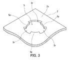
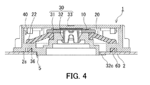
図1及び図2に示す通り、通気部品1は、通気膜10と、通気弁20と、構造部材30とを備えている。通気部品1は、図3に示すような、通気口5を有する筐体2に装着される部品である。図4に示す通り、通気部品1は、通気口5において筐体2に装着される。図4及び図5に示す通り、通気弁20は、弾性体を含み、弾性体の弾性変形により開閉する。構造部材30は、通気膜10及び通気弁20を支持する。通気部品1が筐体2に装着された装着状態において、通気膜10によって筐体2の内部及び外部の通気が行われる。加えて、装着状態において、筐体2の内部の圧力と筐体2の外部の圧力との差が所定の圧力以上になったときに通気弁20が開いて筐体2の内部の気体が筐体2の外部に排出される。換言すると、筐体2の内部の圧力と筐体2の外部の圧力との差が所定の圧力未満である場合には、通気弁20は閉じている。通気弁20に含まれる弾性体は、下記(1)の式によって決定される破断強度の変化率が95%〜120%であるゴムによって形成されている。本明細書においてこのゴムを「耐熱ゴム」と呼ぶ。式(1)において、第一破断強度は、ダンベル状3号形に打ち抜かれた2.0mmの厚みを有するゴム製の試験片を、JIS K 6257:2010に規定された熱抵抗性試験A法に従って加熱した後に、500mm/分の引張速度で引張試験したときの破断強度である。加えて、第二破断強度は、上記の試験片を上記の熱抵抗性試験A法に従って加熱することなく、500mm/分の引張速度で引張試験したときの破断強度である。
破断強度の変化率=100×第一破断強度/第二破断強度 (1)As shown in FIGS. 1 and 2, the ventilation component 1 includes a
Rate of change in breaking strength = 100 x first breaking strength / second breaking strength (1)
通気弁20に含まれる弾性体が耐熱ゴムによって形成されていることにより、通気弁20が高温環境で使用されても、通気弁20の弾性体をなす耐熱ゴムの破断強度が変化しにくい。この場合、通気部品1の使用期間中に、通気弁20が開く圧力が変化しにくく所望の範囲に収まりやすいと考えられる。このことは、通気部品1又は通気部品1が装着された製品の信頼性を高めるうえで有利である。 Since the elastic body included in the
通気部品1における弾性体をなす耐熱ゴムの第一破断強度及び第二破断強度の値は、典型的には、通気部品1の出荷時における値を意味する。例えば、通気部品1における弾性体をなす耐熱ゴムの原料と同一の原料を用いて通気弁20に含まれる弾性体の成形条件に準じて上記の試験片を作製する。 The values of the first breaking strength and the second breaking strength of the heat-resistant rubber forming the elastic body in the ventilation component 1 typically mean the values at the time of shipment of the ventilation component 1. For example, the above test piece is produced by using the same raw material as the raw material of the heat-resistant rubber forming the elastic body in the ventilation component 1 according to the molding conditions of the elastic body included in the
耐熱ゴムは、上記の破断強度の変化率が95%〜120%である限り、特定のゴムに限定されない。耐熱ゴムは、ACM、AEM、ANM、CM、CSM、EBM、EOM、EPDM、EPM、EVM、FEPM、FFKM、FKM、IM、NBM、SEBM、SEPM、CO、ECO、GCO、GECO、GPO、FMQ、FVMQ、MQ、PMQ、PVMQ、VMQ、ABR、BR、CR、CR、ENR、HNBR、IIR、IR、MSBR、NBIR、NBR、NIR、NR、NOR、PBR、PSBR、SBR、E−SBR、S−SBR、SIBR、XBR、XCR、XNBR、XSBR、BIIR、CIIR、OT、EOT、AFMU、AU、EU、FZ、又はPZでありうる。なお、これらの略号は、JIS K 6397:2005に従って記載している。 The heat-resistant rubber is not limited to a specific rubber as long as the rate of change in breaking strength is 95% to 120%. Heat resistant rubber includes ACM, AEM, ANM, CM, CSM, EBM, EOM, EPDM, EPM, EVM, FEPM, FFKM, FKM, IM, NBM, SEBM, SEPM, CO, ECO, GCO, GECO, GPO, FMQ, FVMQ, MQ, PMQ, PVMQ, VMQ, ABR, BR, CR, CR, ENR, HNBR, IIR, IR, MSBR, NBIR, NBR, NIR, NR, NOR, PBR, PSBR, SBR, E-SBR, S- It can be SBR, SIBR, XBR, XCR, XNBR, XSBR, BIIR, CIIR, OT, EOT, AFMU, AU, EU, FZ, or PZ. These abbreviations are described in accordance with JIS K 6397: 2005.
通気部品1における弾性体をなす耐熱ゴムの第二破断強度は、例えば、5〜10MPaである。これにより、より確実に、通気部品1の使用期間中に、通気弁20が開く圧力が所望の範囲に収まりやすい。通気部品1における弾性体をなす耐熱ゴムの第二破断強度は、望ましくは6〜9MPaであり、より望ましくは7〜8MPaである。 The second breaking strength of the heat-resistant rubber forming the elastic body in the ventilation component 1 is, for example, 5 to 10 MPa. As a result, the pressure at which the
HIS−30、HIS−35、HIS−40、HIS−45、HIS−50、HIS−55、及びHIS−60につき、第一破断強度、第二破断強度、及び破断強度の変化率を求めた。結果を表1に示す。これらは、シリコーンゴムである。表1に示す通り、HIS−30、HIS−40、HIS−45、HIS−50、HIS−55、及びHIS−60は、耐熱ゴムとして使用可能である。 For HIS-30, HIS-35, HIS-40, HIS-45, HIS-50, HIS-55, and HIS-60, the first breaking strength, the second breaking strength, and the rate of change of the breaking strength were determined. The results are shown in Table 1. These are silicone rubbers. As shown in Table 1, HIS-30, HIS-40, HIS-45, HIS-50, HIS-55, and HIS-60 can be used as heat-resistant rubber.

図2に示す通り、通気弁20は、例えば、対向する2つの面20f及び20sを有する略板状の構造部分を含む。この構造部分は弾性体によって形成されており、この弾性体は耐熱ゴムによって形成されている。加えて、構造部分の最小厚みは、例えば、2.0mm〜4.0mmである。耐熱ゴムの、JIS K 6253−3:2012に規定されたデュロメータ硬さは、例えば、A30〜80である。 As shown in FIG. 2, the
図6A及び図6Bに示す通り、通気弁20は、いわゆるアンブレラバルブ(傘型の開放弁)の一種であり、例えば、2つの面20f及び20sの一方を平面視したときに内周部21及び外周部22を含む円環状の形状を有する。通気弁20は、その中央に貫通穴25を有している。内周部21は、貫通穴25に隣接している。加えて、図2に示す通り、構造部材30は、支持部35と、弁座部36とを有する。支持部35は、内周部21を支持する。図4及び図5に示す通り、弁座部36は、通気弁20が閉じたときに外周部22に接触し、かつ、通気弁が開いたときに外周部22と離れている。アンブレラバルブは、通常、開閉を担う弁部と弁部を支持する軸部とを含んでいる。弁部をなす部材と、軸部をなす他の部材とを別々に有するアンブレラバルブもある。通気弁20は、例えば、弁部のみをなしており、弁部を平面視したときに円環状の形状を有する。一方、構造部材30は、弁部である通気弁20を支持する軸部の役割を果たしている。通気弁20の貫通穴25は、構造部材30によって通気弁20を支持するために利用される。また、通気部品1を平面視したときに、通気弁20の貫通穴25を形成する内周面より内側に通気膜10が配置されている。このように、通気弁20の貫通穴25は、通気膜10の収容のために十分な大きさを有している。 As shown in FIGS. 6A and 6B, the
通気弁20は、弾性変形によって開き、変形前の形状に戻ることによって閉じるものである限り、その形状は特定のものに限定されない。通気弁20は、いわゆるダックビルバルブ型のものであってもよいし、アンブレラバルブ型のものであってもよい。通気弁20がアンブレラバルブである場合、通気弁20は、弁部と軸部とを含んでなるものであってもよく、弁部のみからなるものであってもよい。また、通気弁20が弁部のみからなるアンブレラバルブである場合、通気弁20は、貫通穴を有するものであってもよく、貫通穴を有しないものであってもよい。通気弁20が貫通穴を有するアンブレラバルブである場合、その貫通穴の形状は特定の形状に限定されず、貫通穴の寸法は特定の値に限定されない。 The shape of the
図1及び図2に示す通り、構造部材30は、例えば、係合部32cを有する。係合部32cは、筐体2の通気口5に差し込まれる。通気部品1は、例えば、シール部材60をさらに備えている。図4に示す通り、シール部材60は、装着状態において、構造部材30と、筐体2の通気部品1が装着される外面2sとの隙間をシールする。これにより、構造部材30と外面2sとの間を液体が通過して筐体2の内部に液体が導かれることを防止できる。シール部材60は、例えば、O−リング又はパッキンである。シール部材60の材料は、例えば、弾性変形可能な材料である。 As shown in FIGS. 1 and 2, the
シール部材60の材料は、例えば、天然ゴム、合成ゴム、又は熱可塑性エラストマー等のエラストマーである。この場合、合成ゴムは、例えば、NBR、EPDM、シリコーンゴム、フッ素ゴム、アクリルゴム、又は水素化ニトリルゴムである。 The material of the sealing
通気膜10は、所望の通気性を有する限り特定の膜に限定されない。通気膜10は、単層膜であってよいし、多層膜であってもよい。通気膜10が多層膜である場合、各層は、多孔質膜、不織布、クロス、及びメッシュからなる群より選ばれる1つでありうる。通気膜10は、多孔質膜及び不織布を含んでいてよく、クロス及びメッシュの少なくとも1つと多孔質膜とを含んでいてもよく、複数の不織布を含んでいてもよい。通気膜10は、典型的には、有機高分子材料(樹脂)によって構成されている。多孔質膜の材料は、例えば、フッ素樹脂である。フッ素樹脂としては、例えば、ポリテトラフルオロエチレン(PTFE)、ポリクロロトリフルオロエチレン、テトラフルオロエチレン−ヘキサフルオロプロピレン共重合体、又はテトラフルオロエチレン−エチレン共重合体を使用できる。不織布、クロス、及びメッシュの材料は、例えば、ポリエチレンテレフタレート等のポリエステル、ポリエチレン及びポリプロピレン等のポリオレフィン、ナイロン、アラミド、又はエチレン酢酸ビニル共重合体である。 The
通気膜10は、必要に応じて撥液処理されていてもよい。撥液処理は、例えば、パーフルオロアルキル基を有するフッ素系表面修飾剤を含む撥液性の被膜を通気膜10に形成することによってなされる。撥液性の被膜の形成は、特に制限されないが、例えば、エアスプレイ法、静電スプレイ法、ディップコーティング法、スピンコーティング法、ロールコーティング法、カーテンフローコーティング法、又は含浸法等の方法により、パーフルオロアルキル基を有するフッ素系表面修飾剤の溶液又はディスパージョンで樹脂多孔質膜をコーティングすることによりなされる。また、電着塗装法又はプラズマ重合法によって、撥液性の被膜を形成してもよい。 The
通気弁20は、弾性変形によって開き、変形前の形状に戻ることによって閉じる。このため、通気弁20は、開閉を繰り返すことができ、繰り返し使用できる。このことは、通気部品1が筐体2に取り付けられた製品において通気弁20が正常に作動するかどうかを検査した後に、検査後の製品を出荷可能にするという利点をもたらす。 The
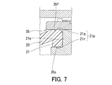
図7に示す通り、支持部35は、例えば、第一接触部35f及び第二接触部35sを有する。第一接触部35f及び第二接触部35sは、通気弁20の内周部21を挟持している。第一接触部35fは、内周部21において対向する一対の面21pの一方である面21qに接触している。加えて、第二接触部35sは、内周部21において一対の面21pの他方である面21rに接触している。支持部35は、第一接触部35fと第二接触部35sとの間で、一対の面21pを接続している内周部21の端面21eに接触している。内周部21は、第一接触部35f及び第二接触部35sによって挟持されているとともに、端面21eにおいても支持部35と接触している。このため、通気弁20と支持部35とのシール性が高い。その結果、支持部35と内周部21との間を液体及び気体が通過せず、通気部品1及び通気部品1が装着された製品の信頼性を高めることができる。 As shown in FIG. 7, the
例えば、通気弁20の弾性体が弾性変形により支持部35に押し付けられた状態で、内周部21の端面21eが支持部35に接触している。この場合、通気弁20と支持部35とのシール性が高い。 For example, the
内周部21は、例えば、端面21eにおいて支持部35と液密に接触している。内周部21は、望ましくは、端面21eにおいて支持部35と液密かつ気密に接触している。この場合、通気弁20と支持部35とのシール性がより高くなりやすい。この場合、気密とは、端面21eによって仕切られた2つの空間の圧力差を10kPa以上に保つことができることを意味する。 The inner
第一接触部35f及び第二接触部35sは、例えば、通気弁20の弾性体が弾性変形するように内周部21に押し付けられた状態で、内周部21に接触している。第一接触部35f及び第二接触部35sは、例えば、液密に内周部21に接触している。第一接触部35f及び第二接触部35sは、望ましくは、液密かつ気密に内周部21に接触している。この場合、気密とは、第一接触部35f又は第二接触部35sによって仕切られた2つの空間の圧力差を10kPa以上に保つことができることを意味する。 The
図2に示す通り、通気弁20の面20fは、例えば、通気弁20の内周部21に隣接している部分と内周部21との間に段差を有することなく形成されている。これにより、内周部21と支持部35との接触面積が大きくなりやすい。 As shown in FIG. 2, the
図2に示す通り、通気弁20の面20sは、例えば、通気弁20の内周部21に隣接している部分と内周部21との間に段差を有するように形成されている。このため、内周部21の厚みは、通気弁20の内周部21に隣接している部分の厚みよりも大きい。これにより、支持部35によって挟持された内周部21の変形量が大きくなりやすく、通気弁20と支持部35との間のシール性が高い。 As shown in FIG. 2, the
図2に示す通り、通気弁20の構造部分は、通気弁20の外周部22に隣接している部分と外周部22との間に屈曲部を有し、その屈曲部は通気弁20の内側に屈曲している。これにより、通気弁20が閉じた状態で、外周部22と弁座部36との接触面積が大きくなりやすい。その結果、通気弁20が閉じた状態で、外周部22と弁座部36との間のシール性が高い。 As shown in FIG. 2, the structural portion of the
図2に示す通り、構造部材30は、例えば、第一部材31と、第二部材32とを備えている。第一部材31は、通気膜10を支持している。第一部材31は、基部31bと、軸部31sとを備えている。基部31bは、例えば、円板状であり、通気膜10を支持している。基部31bは、その中央に通気のための貫通穴31hを有する。基部31bは、基部31bの軸線に垂直な方向において貫通穴31hの外側で通気膜10の周縁部を支持している。通気膜10は、例えば、熱溶着、超音波溶着、又は接着剤による接着等の方法によって、基部31bに固定されている。軸部31sは、基部31bの中央から基部31bの軸線方向に突出している。軸部31sは、筒状であり、基部31bの軸線方向において基部31bから離れた位置に複数(例えば3つ)の脚部31gを有する。複数の脚部31gは、例えば、基部31bの軸線周りに等角で離れて配置されている。複数の脚部31gのそれぞれは、その先端に、基部31bの軸線に垂直な方向に向かって突出する係合部31cを有する。軸部31sの内部又は脚部31g同士の間及び貫通穴31hをガスが出入りして通気が行われる。 As shown in FIG. 2, the
第二部材32は、構造部材30の底部及び側部をなしている。第二部材32は、環状の部材であり、内周部32i、外周部32e、及び連結部32kを備えている。内周部32iは、第二部材32の中央に位置しており、筒状である。外周部32eは、内周部32iの軸線に垂直な方向に内周部32iから離れて内周部32iを取り囲んでおり、筒状である。外周部32eは、構造部材30の側部をなしている。連結部32kは、内周部32iの軸線に垂直な方向において外周部32eと内周部32iとの間に位置し、外周部32eと内周部32iとを連結している。内周部32i及び連結部32kが構造部材30の底部をなしている。内周部32iは、その中央に貫通孔である取付孔32hを有する。第一部材31は、軸線方向における内周部32iの一方の端部において第二部材32に取り付けられている。内周部32iの一方の端部において取付孔32hはテーパー孔をなしている。加えて、内周部32iは、テーパー孔に隣接しており、内周部32iの軸線に垂直な方向に延びている環状の係合面32fを有する。取付孔32hのテーパー孔に軸部31sが差し込まれ、係合部31cが係合面32fと向かい合うことによって、第一部材31が取付孔32hから外れることが防止されている。加えて、内周部32iの軸線方向におけるテーパー孔に隣接した内周部32iの端面は、第一部材31の基部31bの底面と向かい合っている。 The
支持部35は、例えば、第一部材31の基部31bの底面と、軸線方向における内周部32iの一方の端部の外面とによって形成されている。 The
内周部32iの内周面は、係合面32fから、軸線方向における内周部32iの他方の端部に向かって複数(例えば、3つ)の段をなすように形成されている。例えば、内周部32iの内周面は、第一側面32p、第二側面32q、第三側面32r、第一接続面32t、及び第二接続面32uを有する。第一側面32p、第二側面32q、及び第三側面32rは、内周部32iの軸線方向に延びている。加えて、第一側面32p、第二側面32q、及び第三側面32rは、それぞれ、第一内径、第二内径、及び第三内径を有する。第一内径は第二内径より小さく、かつ、第二内径は第三内径より小さい。第一接続面32t及び第二接続面32uは、内周部32iの軸線に垂直な方向に延びている。第一接続面32tは、第一側面32pと第二側面32qとを接続している。第二接続面32uは、第二側面32qと第三側面32rとを接続している。 The inner peripheral surface of the inner
図1に示す通り、内周部32iは、例えば、複数(例えば、3つ)の係合部32cを備える。係合部32cは、例えば、内周部32iの軸線方向における内周部32iの他方の端部において、内周部32iの軸線に垂直な方向に外側に突出している。係合部32cは、例えば、円弧状に湾曲した板状の部分である。複数の係合部32cは、例えば、内周部32iの軸線周りに等角で離れて配置されている。図3に示す通り、筐体2において、通気口5の一部は、複数(例えば、3つ)の突出部5pによって形成されている。複数の突出部5pは、通気口5の軸線周りに等角で離れて配置されており、突出部5p同士の間に、通気口5の一部をなす複数の溝5rが存在する。通気部品1を筐体2に装着するとき、係合部32cが溝5rを通過するように通気部品1が通気口5に差し込まれる。その後、筐体2の内部で係合部32cが突出部5pと向かい合うように、通気部品1が内周部32iの軸線周りに所定の角度で回転させられて通気部品1が筐体2に装着される。突出部5pと係合部32cとの協働により通気部品1が筐体2から外れることが防止される。 As shown in FIG. 1, the inner
通気弁20は、支持部35の一部をなす内周部32iの外周面と接触するように内周部32iに取り付けられている。例えば、通気弁20の貫通穴25の穴径は、内周部32iの外周面と接触できるように定められている。 The
連結部32kは、例えば、弁座部36を有し、通気弁20に対する弁座としての役割を担う。弁座部36は、連結部32kの周縁部に位置している。連結部32kは、ガスを流すための流路32dを有する。流路32dは、弁座部36と内周部32iとの間において、内周部32iの軸線方向に連なるように形成されている。通気弁20は、流路32dによって、筐体2の内部の圧力を受ける。 The connecting
連結部32kは、例えば、環状溝32gをさらに有する。環状溝32gには、シール部材60が収容されている。環状溝32gは、例えば、内周部32iの軸線に垂直な方向において、弁座部36と重なるように連結部32kの底面に形成されている。 The connecting
外周部32eは、連結部32kの外側において、内周部32iの軸線方向に沿って延びている。外周部32eは、内周部32iの軸線に垂直な方向に外側に突出した外方突出部32jを有する。 The outer
外周部32eは、例えば、複数の内方突出部32vを有する。内方突出部32vは、内周部32iの軸線方向における外周部32eの一方の端部において、内周部32iの軸線に垂直な方向に内側に突出している。複数の内方突出部32vは、内周部32iの軸線周りに所定の間隔で離れて配置されている。 The outer
図1及び図2に示す通り、構造部材30は、例えば、第三部材33をさらに備えている。第三部材33は、例えば、円板状の部材である。第三部材33は、第一部材31及び第二部材32と協働して内部空間40を形成している。通気膜10及び通気弁20は、例えば、内部空間40に収容されている。第三部材33は、通気膜10及び通気弁20を覆っており、通気膜10及び通気弁20を保護している。 As shown in FIGS. 1 and 2, the
第三部材33は、円板状の蓋部33cと、係合爪33eを有する。係合爪33eは、蓋部33cの一方の主面の周縁部から蓋部33cの軸線方向に突出している。係合爪33eの先端部は、蓋部33cの軸線に垂直な方向に外側に突出している。係合爪33eが内方突出部32v同士の隙間を通過するように第三部材33が外周部32eの内部に差し込まれる。その後、係合爪33eの先端部が内方突出部32vと向かい合うように、第三部材33が蓋部33cの軸線周りに所定の角度で回転させられる。このようにして、第三部材33が第二部材32に取り付けられる。係合爪33eの先端部が内方突出部32vと向かい合っていることによって、第三部材33が第二部材32から外れることが防止される。 The
図1に示す通り、構造部材30は、通気路50を有する。通気路50は、内部空間40と通気部品1の外部空間とを通気可能に連通している。通気路50は、例えば、連結部32kと外周部32eの内面との間に形成されている。 As shown in FIG. 1, the
構造部材30の材料は、例えば、合成樹脂又は金属である。合成樹脂としては、例えば、熱可塑性樹脂を使用できる。熱可塑性樹脂は、例えば、ポリブチレンテレフタレート(PBT)、ポリエチレンテレフタレート(PET)、ポリフェニレンサルファイド(PPS)、ポリサルフォン(PS)、ポリプロピレン(PP)、ポリエチレン(PE)、又はABS樹脂である。構造部材30の材料は、熱可塑性樹脂を母材とする複合材料であってもよい。この場合、複合材料に添加される強化剤は、ガラス繊維、炭素繊維、金属、又は無機フィラーでありうる。 The material of the
図4に示す通り、筐体2の内部の圧力と筐体2の外部の圧力との差が所定の圧力未満である場合、通気弁20は閉じており、筐体2の内部のガスは、流路32dを通って筐体2の外部に移動できない。このため、ガスは、内周部32iの取付孔32h、第一部材31の貫通穴31h、通気膜10、内部空間40、及び通気路50を含む流路を通って筐体2の内部及び外部を出入りする。一方、図5に示す通り、筐体2の内部の圧力と筐体2の外部の圧力との差が所定の圧力以上である場合、通気弁20が開き、筐体2の内部のガスは、流路32d、内部空間40、及び通気路50を含む流路を通って筐体2の外部に排出される。通気弁20が開くことによって形成されるガスの流路には、通気膜10が配置されておらず、筐体2の内部から多量のガスを短期間に排出できる。なお、筐体内部の圧力が急上昇することによって、通気弁を備えていても通気膜等が破損してしまうことがある。しかし、通気部品1は、そのような現象を抑制できる構造を有する。通気膜等の破損を防止する手段として、通気弁を利用して筐体内部のガスを速やかに筐体外部に排出できる構造を提供することが考えらえる。そのためには、ガスが通過する流路の断面積の広さと、それを塞ぐ通気弁の弁部の大きさとを調整することが重要である。通気部品1は、平面視したときに、通気弁20が中央に貫通穴を有する円環状の形状を有している。さらに、通気部品1は、平面視したときに通気弁20の貫通穴25を形成する内周面より内側に通気膜10が位置するように通気膜10が収容される構造を有している。このため、通気部品1における限られた空間で、ガスが通過する流路の断面積及び通気弁20の弁部が可能な限り大きく確保されている。これにより、筐体2の内部の圧力が急上昇したときに、通気弁20が開いて速やかに流路32d、内部空間40、及び通気路50を含む流路を通って筐体2の外部に排出される。 As shown in FIG. 4, when the difference between the pressure inside the
通気部品1は、様々な観点から変更可能である。例えば、通気弁20は、2つの面20f及び20sの一方を平面視したときに円環状以外の環状の形状を有していてもよい。この場合、2つの面20f及び20sの一方を平面視したときに、内周部21及び外周部22の輪郭の輪郭線の一部又は全部は、曲線であってもよいし、直線であってもよい。
The ventilation component 1 can be changed from various viewpoints. For example, the
Claims (5)
通気膜と、
弾性体を含み、前記弾性体の弾性変形により開閉する通気弁と、
前記通気膜及び前記通気弁を支持する構造部材と、を備え、
当該通気部品が前記筐体に装着された装着状態において、前記通気膜によって前記筐体の内部及び外部の通気が行われ、かつ、前記筐体の内部の圧力と前記筐体の外部の圧力との差が所定の圧力以上になったときに前記通気弁が開いて前記筐体の内部の気体が前記筐体の外部に排出され、
前記弾性体は、下記(1)の式によって決定される破断強度の変化率が95%〜120%であるゴムによって形成されている、通気部品。
破断強度の変化率=100×第一破断強度/第二破断強度 (1)
前記第一破断強度は、ダンベル状3号形に打ち抜かれた2.0mmの厚みを有する前記ゴム製の試験片を、日本工業規格(JIS) K 6257:2010に規定された熱抵抗性試験A法に従って加熱した後に、500mm/分の引張速度で引張試験したときの破断強度である。
前記第二破断強度は、前記試験片を、前記熱抵抗性試験A法に従って加熱することなく、500mm/分の引張速度で引張試験したときの破断強度である。A ventilation component that is attached to the housing at the ventilation port.
Breathable membrane and
A vent valve that includes an elastic body and opens and closes due to elastic deformation of the elastic body,
The vent film and the structural member supporting the vent valve are provided.
In the mounted state in which the ventilation component is mounted on the housing, the ventilation film ventilates the inside and outside of the housing, and the pressure inside the housing and the pressure outside the housing. When the difference between the two pressures becomes equal to or higher than a predetermined pressure, the vent valve is opened and the gas inside the housing is discharged to the outside of the housing.
The elastic body is a ventilation component formed of rubber having a rate of change in breaking strength determined by the following formula (1) of 95% to 120%.
Rate of change in breaking strength = 100 x first breaking strength / second breaking strength (1)
The first breaking strength is a thermal resistance test A specified in Japanese Industrial Standards (JIS) K 6257: 2010 for the rubber test piece having a thickness of 2.0 mm punched into a dumbbell-shaped No. 3 shape. It is the breaking strength when a tensile test is performed at a tensile speed of 500 mm / min after heating according to the method.
The second breaking strength is the breaking strength when the test piece is subjected to a tensile test at a tensile speed of 500 mm / min without heating according to the thermal resistance test A method.
前記構造部分の最小厚みが2.0mm〜4.0mmであり、
前記ゴムの、JIS K 6253−3:2012に規定されたデュロメータ硬さがA30〜80である、
請求項1又は2に記載の通気部品。The vent valve comprises a substantially plate-like structural portion having two opposing surfaces formed by the elastic body.
The minimum thickness of the structural portion is 2.0 mm to 4.0 mm.
The durometer hardness of the rubber specified in JIS K 6253-: 2012 is A30-80.
The ventilation component according to claim 1 or 2.
前記構造部材は、前記内周部を支持する支持部と、前記通気弁が閉じたときに前記外周部に接触し、かつ、前記通気弁が開いたときに前記外周部と離れている弁座部とを有する、請求項1〜3のいずれか1項に記載の通気部品。The vent valve includes a substantially plate-like structural portion formed by the elastic body and having two opposing surfaces, and has an inner peripheral portion and an outer peripheral portion when one of the two surfaces is viewed in a plan view. Has an annular shape, including
The structural member has a support portion that supports the inner peripheral portion and a valve seat that is in contact with the outer peripheral portion when the vent valve is closed and is separated from the outer peripheral portion when the vent valve is opened. The ventilation component according to any one of claims 1 to 3, further comprising a part.
前記装着状態において、前記構造部材と前記筐体の当該通気部品が装着される外面との隙間をシールするシール部材をさらに備えた、
請求項1〜4のいずれか1項に記載の通気部品。
The structural member has an engaging portion that is inserted into the vent of the housing.
Further provided with a sealing member for sealing the gap between the structural member and the outer surface on which the ventilation component of the housing is mounted in the mounted state.
The ventilation component according to any one of claims 1 to 4.
Priority Applications (1)
| Application Number | Priority Date | Filing Date | Title |
|---|---|---|---|
| JP2023144963A JP2023179453A (en) | 2018-10-25 | 2023-09-07 | Ventilation component |
Applications Claiming Priority (3)
| Application Number | Priority Date | Filing Date | Title |
|---|---|---|---|
| JP2018201128 | 2018-10-25 | ||
| JP2018201128 | 2018-10-25 | ||
| PCT/JP2019/040957 WO2020085212A1 (en) | 2018-10-25 | 2019-10-17 | Ventilation component |
Related Child Applications (1)
| Application Number | Title | Priority Date | Filing Date |
|---|---|---|---|
| JP2023144963A Division JP2023179453A (en) | 2018-10-25 | 2023-09-07 | Ventilation component |
Publications (1)
| Publication Number | Publication Date |
|---|---|
| JPWO2020085212A1 true JPWO2020085212A1 (en) | 2021-09-16 |
Family
ID=70331396
Family Applications (2)
| Application Number | Title | Priority Date | Filing Date |
|---|---|---|---|
| JP2020553307A Pending JPWO2020085212A1 (en) | 2018-10-25 | 2019-10-17 | Ventilation parts |
| JP2023144963A Pending JP2023179453A (en) | 2018-10-25 | 2023-09-07 | Ventilation component |
Family Applications After (1)
| Application Number | Title | Priority Date | Filing Date |
|---|---|---|---|
| JP2023144963A Pending JP2023179453A (en) | 2018-10-25 | 2023-09-07 | Ventilation component |
Country Status (5)
| Country | Link |
|---|---|
| US (1) | US11536383B2 (en) |
| JP (2) | JPWO2020085212A1 (en) |
| CN (2) | CN116928411A (en) |
| DE (1) | DE112019005336T5 (en) |
| WO (1) | WO2020085212A1 (en) |
Families Citing this family (3)
| Publication number | Priority date | Publication date | Assignee | Title |
|---|---|---|---|---|
| CN114198543B (en) * | 2020-08-31 | 2023-08-08 | 宁德时代新能源科技股份有限公司 | Bidirectional pressure release valve, battery and electricity utilization device |
| DE102021102444A1 (en) | 2021-02-03 | 2022-08-04 | Carl Freudenberg Kg | Pressure equalization device and housing enclosing the pressure equalization device |
| EP4297165A1 (en) * | 2022-06-22 | 2023-12-27 | Newfrey LLC | Ventilation device for a battery |
Citations (8)
| Publication number | Priority date | Publication date | Assignee | Title |
|---|---|---|---|---|
| JPS55158359U (en) * | 1979-04-30 | 1980-11-14 | ||
| JP2004067831A (en) * | 2002-08-05 | 2004-03-04 | Jsr Corp | Rubber composition, rubber molded product and their preparation processes |
| WO2008111356A1 (en) * | 2007-03-09 | 2008-09-18 | Asahi Rubber Inc. | Excessive pressure relief valve, and relief valve unit having the relief valve |
| DE202015100970U1 (en) * | 2015-02-27 | 2015-03-23 | Samson Ag | vent valve |
| JP2016056902A (en) * | 2014-09-11 | 2016-04-21 | 藤倉ゴム工業株式会社 | Check valve structure |
| WO2018183804A1 (en) * | 2017-03-30 | 2018-10-04 | Donaldson Company, Inc. | Vent with relief valve |
| US20180292020A1 (en) * | 2017-04-06 | 2018-10-11 | Carl Freudenberg Kg | Pressure-compensation device for a housing |
| WO2018199238A1 (en) * | 2017-04-28 | 2018-11-01 | 日東電工株式会社 | Gas-permeable unit |
Family Cites Families (9)
| Publication number | Priority date | Publication date | Assignee | Title |
|---|---|---|---|---|
| JPS6023861B2 (en) * | 1977-10-19 | 1985-06-10 | 株式会社東芝 | UV irradiation device |
| EP0471294B1 (en) * | 1990-08-15 | 1995-03-01 | Horstine Farmery Limited | Apparatus for dispensing agricultural chemicals |
| US5981099A (en) * | 1998-01-20 | 1999-11-09 | Accuma Corporation | Pressure relief valve for electric storage batteries |
| WO2005056612A1 (en) * | 2003-12-08 | 2005-06-23 | Nitta Corporation | Rubbery product or rubbery substance containing product |
| JP2008291911A (en) * | 2007-05-24 | 2008-12-04 | Alps Electric Co Ltd | Valve device |
| DE102011080325A1 (en) * | 2011-08-03 | 2013-02-07 | Elringklinger Ag | Pressure equalization device for a housing of an electrochemical device |
| JP6130183B2 (en) * | 2013-03-26 | 2017-05-17 | 日東電工株式会社 | Ventilation member |
| JP6265532B2 (en) * | 2014-02-03 | 2018-01-24 | 株式会社細川洋行 | Bag body with pouring tool |
| JP6670594B2 (en) * | 2015-11-18 | 2020-03-25 | 株式会社パイオラックス | Check valve |
-
2019
- 2019-10-17 US US17/287,276 patent/US11536383B2/en active Active
- 2019-10-17 DE DE112019005336.1T patent/DE112019005336T5/en active Pending
- 2019-10-17 JP JP2020553307A patent/JPWO2020085212A1/en active Pending
- 2019-10-17 CN CN202310796515.6A patent/CN116928411A/en active Pending
- 2019-10-17 CN CN201980068852.5A patent/CN112867887B/en active Active
- 2019-10-17 WO PCT/JP2019/040957 patent/WO2020085212A1/en active Application Filing
-
2023
- 2023-09-07 JP JP2023144963A patent/JP2023179453A/en active Pending
Patent Citations (8)
| Publication number | Priority date | Publication date | Assignee | Title |
|---|---|---|---|---|
| JPS55158359U (en) * | 1979-04-30 | 1980-11-14 | ||
| JP2004067831A (en) * | 2002-08-05 | 2004-03-04 | Jsr Corp | Rubber composition, rubber molded product and their preparation processes |
| WO2008111356A1 (en) * | 2007-03-09 | 2008-09-18 | Asahi Rubber Inc. | Excessive pressure relief valve, and relief valve unit having the relief valve |
| JP2016056902A (en) * | 2014-09-11 | 2016-04-21 | 藤倉ゴム工業株式会社 | Check valve structure |
| DE202015100970U1 (en) * | 2015-02-27 | 2015-03-23 | Samson Ag | vent valve |
| WO2018183804A1 (en) * | 2017-03-30 | 2018-10-04 | Donaldson Company, Inc. | Vent with relief valve |
| US20180292020A1 (en) * | 2017-04-06 | 2018-10-11 | Carl Freudenberg Kg | Pressure-compensation device for a housing |
| WO2018199238A1 (en) * | 2017-04-28 | 2018-11-01 | 日東電工株式会社 | Gas-permeable unit |
Also Published As
| Publication number | Publication date |
|---|---|
| JP2023179453A (en) | 2023-12-19 |
| CN112867887B (en) | 2023-09-22 |
| US20210396324A1 (en) | 2021-12-23 |
| WO2020085212A1 (en) | 2020-04-30 |
| US11536383B2 (en) | 2022-12-27 |
| CN116928411A (en) | 2023-10-24 |
| CN112867887A (en) | 2021-05-28 |
| DE112019005336T5 (en) | 2021-07-15 |
Similar Documents
| Publication | Publication Date | Title |
|---|---|---|
| JP2023179453A (en) | Ventilation component | |
| JP7386803B2 (en) | ventilation parts | |
| US9120059B2 (en) | Ventilation unit | |
| JP4498996B2 (en) | Enclosure ventilation structure | |
| KR20180002622A (en) | Unit for regulating or controlling fluid pressure | |
| WO2015186279A1 (en) | Housing kit and aerated housing | |
| JP2007141629A (en) | Venting member | |
| JP7034581B2 (en) | Ventilation member | |
| US11811081B2 (en) | Ventilation unit | |
| CN103503588A (en) | Ventilation unit | |
| JP2024001893A (en) | Ventilation component | |
| JP6538863B2 (en) | Vent device | |
| CN110574503B (en) | Ventilation member | |
| US20170095763A1 (en) | Bag filter arrangement | |
| JPWO2020075848A1 (en) | Ventilation housing | |
| WO2019135399A1 (en) | Casing kit and ventilation member | |
| JP7399893B2 (en) | Ventilation parts and ventilation structures | |
| TW201939646A (en) | Substrate storage container | |
| KR102634104B1 (en) | vent parts | |
| JPH07243363A (en) | Breather | |
| JPH09144600A (en) | Air vent device for engine carburetor | |
| JPH1019150A (en) | Check valve |
Legal Events
| Date | Code | Title | Description |
|---|---|---|---|
| A621 | Written request for application examination |
Free format text: JAPANESE INTERMEDIATE CODE: A621 Effective date: 20220428 |
|
| A131 | Notification of reasons for refusal |
Free format text: JAPANESE INTERMEDIATE CODE: A131 Effective date: 20230207 |
|
| A02 | Decision of refusal |
Free format text: JAPANESE INTERMEDIATE CODE: A02 Effective date: 20230613 |
|
| A521 | Request for written amendment filed |
Free format text: JAPANESE INTERMEDIATE CODE: A523 Effective date: 20230907 |
|
| A911 | Transfer to examiner for re-examination before appeal (zenchi) |
Free format text: JAPANESE INTERMEDIATE CODE: A911 Effective date: 20230915 |
|
| A912 | Re-examination (zenchi) completed and case transferred to appeal board |
Free format text: JAPANESE INTERMEDIATE CODE: A912 Effective date: 20231102 |
|
| RD02 | Notification of acceptance of power of attorney |
Free format text: JAPANESE INTERMEDIATE CODE: A7422 Effective date: 20240129 |