JPWO2017191702A1 - Image processing device - Google Patents
Image processing device Download PDFInfo
- Publication number
- JPWO2017191702A1 JPWO2017191702A1 JP2018515395A JP2018515395A JPWO2017191702A1 JP WO2017191702 A1 JPWO2017191702 A1 JP WO2017191702A1 JP 2018515395 A JP2018515395 A JP 2018515395A JP 2018515395 A JP2018515395 A JP 2018515395A JP WO2017191702 A1 JPWO2017191702 A1 JP WO2017191702A1
- Authority
- JP
- Japan
- Prior art keywords
- image
- virtual
- virtual space
- information
- image processing
- Prior art date
- Legal status (The legal status is an assumption and is not a legal conclusion. Google has not performed a legal analysis and makes no representation as to the accuracy of the status listed.)
- Granted
Links
Images
Classifications
-
- G—PHYSICS
- G06—COMPUTING; CALCULATING OR COUNTING
- G06T—IMAGE DATA PROCESSING OR GENERATION, IN GENERAL
- G06T19/00—Manipulating 3D models or images for computer graphics
- G06T19/20—Editing of 3D images, e.g. changing shapes or colours, aligning objects or positioning parts
-
- A—HUMAN NECESSITIES
- A63—SPORTS; GAMES; AMUSEMENTS
- A63F—CARD, BOARD, OR ROULETTE GAMES; INDOOR GAMES USING SMALL MOVING PLAYING BODIES; VIDEO GAMES; GAMES NOT OTHERWISE PROVIDED FOR
- A63F13/00—Video games, i.e. games using an electronically generated display having two or more dimensions
- A63F13/20—Input arrangements for video game devices
- A63F13/21—Input arrangements for video game devices characterised by their sensors, purposes or types
- A63F13/211—Input arrangements for video game devices characterised by their sensors, purposes or types using inertial sensors, e.g. accelerometers or gyroscopes
-
- A—HUMAN NECESSITIES
- A63—SPORTS; GAMES; AMUSEMENTS
- A63F—CARD, BOARD, OR ROULETTE GAMES; INDOOR GAMES USING SMALL MOVING PLAYING BODIES; VIDEO GAMES; GAMES NOT OTHERWISE PROVIDED FOR
- A63F13/00—Video games, i.e. games using an electronically generated display having two or more dimensions
- A63F13/20—Input arrangements for video game devices
- A63F13/21—Input arrangements for video game devices characterised by their sensors, purposes or types
- A63F13/213—Input arrangements for video game devices characterised by their sensors, purposes or types comprising photodetecting means, e.g. cameras, photodiodes or infrared cells
-
- A—HUMAN NECESSITIES
- A63—SPORTS; GAMES; AMUSEMENTS
- A63F—CARD, BOARD, OR ROULETTE GAMES; INDOOR GAMES USING SMALL MOVING PLAYING BODIES; VIDEO GAMES; GAMES NOT OTHERWISE PROVIDED FOR
- A63F13/00—Video games, i.e. games using an electronically generated display having two or more dimensions
- A63F13/25—Output arrangements for video game devices
- A63F13/26—Output arrangements for video game devices having at least one additional display device, e.g. on the game controller or outside a game booth
-
- A—HUMAN NECESSITIES
- A63—SPORTS; GAMES; AMUSEMENTS
- A63F—CARD, BOARD, OR ROULETTE GAMES; INDOOR GAMES USING SMALL MOVING PLAYING BODIES; VIDEO GAMES; GAMES NOT OTHERWISE PROVIDED FOR
- A63F13/00—Video games, i.e. games using an electronically generated display having two or more dimensions
- A63F13/50—Controlling the output signals based on the game progress
- A63F13/52—Controlling the output signals based on the game progress involving aspects of the displayed game scene
-
- A—HUMAN NECESSITIES
- A63—SPORTS; GAMES; AMUSEMENTS
- A63F—CARD, BOARD, OR ROULETTE GAMES; INDOOR GAMES USING SMALL MOVING PLAYING BODIES; VIDEO GAMES; GAMES NOT OTHERWISE PROVIDED FOR
- A63F13/00—Video games, i.e. games using an electronically generated display having two or more dimensions
- A63F13/60—Generating or modifying game content before or while executing the game program, e.g. authoring tools specially adapted for game development or game-integrated level editor
- A63F13/65—Generating or modifying game content before or while executing the game program, e.g. authoring tools specially adapted for game development or game-integrated level editor automatically by game devices or servers from real world data, e.g. measurement in live racing competition
-
- G—PHYSICS
- G06—COMPUTING; CALCULATING OR COUNTING
- G06F—ELECTRIC DIGITAL DATA PROCESSING
- G06F3/00—Input arrangements for transferring data to be processed into a form capable of being handled by the computer; Output arrangements for transferring data from processing unit to output unit, e.g. interface arrangements
- G06F3/01—Input arrangements or combined input and output arrangements for interaction between user and computer
- G06F3/03—Arrangements for converting the position or the displacement of a member into a coded form
- G06F3/033—Pointing devices displaced or positioned by the user, e.g. mice, trackballs, pens or joysticks; Accessories therefor
- G06F3/0346—Pointing devices displaced or positioned by the user, e.g. mice, trackballs, pens or joysticks; Accessories therefor with detection of the device orientation or free movement in a 3D space, e.g. 3D mice, 6-DOF [six degrees of freedom] pointers using gyroscopes, accelerometers or tilt-sensors
-
- G—PHYSICS
- G06—COMPUTING; CALCULATING OR COUNTING
- G06T—IMAGE DATA PROCESSING OR GENERATION, IN GENERAL
- G06T15/00—3D [Three Dimensional] image rendering
- G06T15/10—Geometric effects
- G06T15/20—Perspective computation
-
- G—PHYSICS
- G06—COMPUTING; CALCULATING OR COUNTING
- G06T—IMAGE DATA PROCESSING OR GENERATION, IN GENERAL
- G06T19/00—Manipulating 3D models or images for computer graphics
-
- G—PHYSICS
- G06—COMPUTING; CALCULATING OR COUNTING
- G06T—IMAGE DATA PROCESSING OR GENERATION, IN GENERAL
- G06T7/00—Image analysis
- G06T7/70—Determining position or orientation of objects or cameras
-
- A—HUMAN NECESSITIES
- A63—SPORTS; GAMES; AMUSEMENTS
- A63F—CARD, BOARD, OR ROULETTE GAMES; INDOOR GAMES USING SMALL MOVING PLAYING BODIES; VIDEO GAMES; GAMES NOT OTHERWISE PROVIDED FOR
- A63F2300/00—Features of games using an electronically generated display having two or more dimensions, e.g. on a television screen, showing representations related to the game
- A63F2300/80—Features of games using an electronically generated display having two or more dimensions, e.g. on a television screen, showing representations related to the game specially adapted for executing a specific type of game
- A63F2300/8082—Virtual reality
-
- G—PHYSICS
- G06—COMPUTING; CALCULATING OR COUNTING
- G06T—IMAGE DATA PROCESSING OR GENERATION, IN GENERAL
- G06T2219/00—Indexing scheme for manipulating 3D models or images for computer graphics
- G06T2219/20—Indexing scheme for editing of 3D models
- G06T2219/2004—Aligning objects, relative positioning of parts
Landscapes
- Engineering & Computer Science (AREA)
- Multimedia (AREA)
- Theoretical Computer Science (AREA)
- Physics & Mathematics (AREA)
- General Physics & Mathematics (AREA)
- General Engineering & Computer Science (AREA)
- Human Computer Interaction (AREA)
- Computer Graphics (AREA)
- Software Systems (AREA)
- Computer Hardware Design (AREA)
- Computing Systems (AREA)
- Geometry (AREA)
- Architecture (AREA)
- Computer Vision & Pattern Recognition (AREA)
- Processing Or Creating Images (AREA)
- Position Input By Displaying (AREA)
- User Interface Of Digital Computer (AREA)
Abstract
ユーザが頭部に装着して使用する表示装置と接続される画像処理装置であって、当該ユーザの周囲の現実空間の情報を取得し、取得した現実空間の情報に基づいて、当該現実空間内の対象物の位置を検出し、当該検出した各対象物の位置に対応する仮想空間内の位置に、仮想的な物体を配して仮想空間の情報を構成する。そして当該構成された仮想空間の画像を生成して、表示装置に出力する画像処理装置である。
An image processing apparatus that is connected to a display device that is worn on the head of a user and that acquires information on the real space around the user, and based on the acquired information on the real space, The position of the target object is detected, and virtual objects are arranged at positions in the virtual space corresponding to the detected positions of the target objects to constitute information in the virtual space. And it is an image processing apparatus which produces | generates the image of the said comprised virtual space, and outputs it to a display apparatus.
Description
本発明は、ユーザが頭部に装着して使用する表示装置と接続される画像処理装置に関する。 The present invention relates to an image processing apparatus that is connected to a display device that a user wears on the head.
近年、ヘッドマウントディスプレイなど、ユーザが頭部に装着して使用する表示装置が普及しつつある。このような表示装置は、ユーザの目の前に画像を結像させることで、その画像をユーザに閲覧させる。こうした表示装置には、ユーザの眼前を表示部で覆い、ユーザに眼前の現実空間を見せないようにする非透過型のものと、表示部をハーフミラー等で構成し、ユーザに眼前の現実空間を視認させる透過型(光学シースルー方式)のものがある。 In recent years, display devices such as a head-mounted display that are worn by a user on the head are becoming popular. Such a display device causes the user to view the image by forming an image in front of the user's eyes. Such a display device includes a non-transmission type that covers the front of the user with a display unit and prevents the user from seeing the real space in front of the user, and a display unit that includes a half mirror or the like. There is a transmission type (optical see-through method) for visually recognizing.
また、非透過型の表示装置においては、表示させる画像は、例えば、ゲームソフトウエアが生成する仮想的な三次元空間内の画像等とすることができる。 In the non-transparent display device, the image to be displayed can be, for example, an image in a virtual three-dimensional space generated by game software.
さらにこの非透過型の表示装置であっても、別途、カメラで撮影したユーザの眼前の現実空間を表示部に表示することで、透過型の表示装置同様にユーザに眼前の現実空間を視認させる、疑似的に透過型の表示装置を実現するもの(カメラシースルー方式と呼ばれる)が存在する。 Further, even in this non-transmissive display device, the real space in front of the user's eyes photographed by the camera is separately displayed on the display unit, so that the user can visually recognize the real space in front of the eyes as in the transmissive display device. There is a device that realizes a pseudo-transmissive display device (referred to as a camera see-through method).
従来、仮想的な三次元空間(以下仮想空間と呼ぶ)の画像を表示した場合に、この仮想空間内ではユーザの手の届く場所にある物体であっても、現実の空間では当該物体の位置には何もない場合があったり、仮想空間内ではユーザの手の届く場所になにもないのに、現実の空間では物体があって、当該物体に触れてしまったりして、違和感が生じるという問題があった。 Conventionally, when an image in a virtual three-dimensional space (hereinafter referred to as a virtual space) is displayed, even if the object is within the reach of the user's hand in the virtual space, the position of the object in the real space There is nothing in the virtual space, there is nothing in the virtual space that the user can reach, but there is an object in the real space, touching the object, causing a sense of incongruity There was a problem.
本発明は上記実情に鑑みて為されたもので、ユーザに対して仮想空間の画像を、違和感を低減しつつ表示できる画像処理装置を提供することを、その目的の一つとする。 The present invention has been made in view of the above circumstances, and an object of the present invention is to provide an image processing apparatus capable of displaying an image in a virtual space while reducing a sense of discomfort to the user.
上記従来例の問題点を解決する本発明は、ユーザが頭部に装着して使用する表示装置と接続される画像処理装置であって、当該ユーザの周囲の現実空間の情報を取得する情報取得手段と、前記取得した現実空間の情報に基づいて、当該現実空間内の対象物の位置を検出し、当該検出した各対象物の位置に対応する仮想空間内の位置に、仮想的な物体を配して仮想空間の情報を構成する仮想空間構成手段と、前記仮想空間構成手段により構成された仮想空間の画像を生成する画像生成手段と、前記画像生成手段が生成した画像を、前記表示装置に出力する出力手段と、を含むこととしたものである。 The present invention that solves the problems of the above conventional example is an image processing apparatus that is connected to a display device that a user wears on the head, and that acquires information on real space around the user Based on the means and the acquired information on the real space, the position of the object in the real space is detected, and a virtual object is placed at a position in the virtual space corresponding to the position of each detected object. A virtual space forming unit configured to configure virtual space information, an image generating unit configured to generate an image of the virtual space configured by the virtual space forming unit, and an image generated by the image generating unit Output means for outputting to the output.
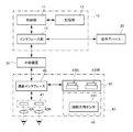
本発明の実施の形態について図面を参照しながら説明する。本発明の実施の形態に係る画像処理装置10を含む画像処理システム1は、図1に例示するように、画像処理装置10と、操作デバイス20と、中継装置30と、表示装置40と、を含んで構成されている。
Embodiments of the present invention will be described with reference to the drawings. As illustrated in FIG. 1, an
画像処理装置10は、表示装置40が表示すべき画像を供給する装置である。例えば画像処理装置10は、家庭用ゲーム機、携帯型ゲーム機、パーソナルコンピューター、スマートフォン、タブレット等である。図1に示されるように、この画像処理装置10は、制御部11と、記憶部12と、インタフェース部13と、を含んで構成される。
The
制御部11は、CPU等のプログラム制御デバイスであり、記憶部12に格納されているプログラムを実行する。本実施の形態では、この制御部11は、表示装置40を装着したユーザの周囲の現実空間の情報を取得し、当該取得した現実空間の情報に基づいて、現実空間内の対象物の位置を検出し、当該検出した各対象物の位置に対応する仮想空間内の位置に、仮想的な物体(仮想対象物と呼ぶ)を配して仮想空間の情報を構成する。
The
またこの制御部11は、当該構成した仮想空間において、別途設定したレンダリングカメラ(仮想空間のレンダリングを行う際に用いる仮想的なカメラ)の位置からの所定視野内の画像を生成し、当該生成した画像を表示装置40に出力する。ここでレンダリングカメラの位置は、ユーザの左目に対応するものと、右目に対応するものとの2つを設定し、それぞれの位置からの視野の仮想空間の画像(左目用画像と右目用画像と)を生成して、当該生成した一対の画像を立体視画像として表示装置40に出力してもよい。以下の例では立体視画像を生成する場合を例として説明する。
In addition, the
具体的に、本実施の形態の一例では、この制御部11は、ユーザの位置と、ユーザの後方とを含むユーザ周囲の所定サイズ(例えば幅(ユーザが表示装置40を装着した時点(つまり初期)のユーザの視線方向に直交し、床面に平行な方向)10m、奥行(床面に平行な初期のユーザの視線方向)10m、高さ3mの直方体範囲)の現実空間(以下、対象空間と呼ぶ)に対応する仮想的な三次元空間(仮想空間)を設定する。そして制御部11は、現実空間の画像を参照しつつ、この仮想空間内に仮想対象物を配し、あるいは映像効果を適用する。
Specifically, in the example of the present embodiment, the
記憶部12は、RAM等のメモリデバイスを少なくとも一つ含み、制御部11が実行するプログラムを格納する。また、この記憶部12は制御部11のワークメモリとしても動作し、制御部11がプログラム実行の過程で使用するデータを格納する。このプログラムは、コンピュータ可読かつ非一時的な記録媒体に格納されて提供され、この記憶部12に格納されたものであってもよい。
The
インタフェース部13は、操作デバイス20や中継装置30との間で画像処理装置10の制御部11がデータ通信を行うためのインタフェースである。画像処理装置10は、インタフェース部13を介して有線又は無線のいずれかで操作デバイス20や中継装置30等と接続される。一例として、このインタフェース部13は、画像処理装置10が供給する画像(立体視画像)や音声を中継装置30に送信するために、HDMI(登録商標)(High-Definition Multimedia Interface)などのマルチメディアインタフェースを含んでよい。また、中継装置30経由で表示装置40から各種の情報を受信したり、制御信号等を送信したりするために、USB等のデータ通信インタフェースを含んでよい。さらにインタフェース部13は、操作デバイス20に対するユーザの操作入力の内容を示す信号を受信するために、USB等のデータ通信インタフェースを含んでよい。
The
操作デバイス20は、家庭用ゲーム機のコントローラ等であって、ユーザが画像処理装置10に対して各種の指示操作を行うために使用される。操作デバイス20に対するユーザの操作入力の内容は、有線又は無線のいずれかにより画像処理装置10に送信される。なお、操作デバイス20は必ずしも画像処理装置10と別体でなくてもよく、画像処理装置10の筐体表面に配置された操作ボタンやタッチパネル等を含んでもよい。本実施の形態の一例では、この操作デバイス20は、ゲームの一時停止を指示する「ポーズボタン」などを含む。
The
中継装置30は、有線又は無線のいずれかにより表示装置40と接続されており、画像処理装置10から供給される立体視画像のデータを受け付けて、受け付けたデータに応じた映像信号を表示装置40に対して出力する。このとき中継装置30は、必要に応じて、供給された立体視画像が表す映像に対して、表示装置40の光学系によって生じる歪みを補正する処理などを実行し、補正された映像を表す映像信号を出力してもよい。なお、中継装置30から表示装置40に供給される映像信号は、立体視画像に基づいて生成した左目用の映像信号と右目用の映像信号との二つの映像信号を含んでいる。また、中継装置30は、立体視画像や映像信号以外にも、音声データや制御信号など、画像処理装置10と表示装置40との間で送受信される各種の情報を中継する。
The
表示装置40は、ユーザが頭部に装着して使用する表示デバイスであって、中継装置30から入力される映像信号に応じた映像を表示し、ユーザに閲覧させる。本実施形態では、表示装置40はユーザの右目と左目とのそれぞれの目の前に、それぞれの目に対応した映像を表示するものとする。この表示装置40は、図1に示したように、映像表示素子41、光学素子42、カメラ43、センサ部44、及び通信インタフェース45を含んで構成される。
The
映像表示素子41は、有機EL表示パネルや液晶表示パネルなどであって、中継装置30から供給される映像信号に応じた映像を表示する。この映像表示素子41は、左目用の映像と右目用の映像とを一列に並べて表示する1つの表示素子であってもよいし、左目用の映像と右目用の映像とをそれぞれ独立に表示する一対の表示素子を含んで構成されてもよい。また、スマートフォン等のディスプレイ画面が、そのまま映像表示素子41として用いられてもよい。この場合、スマートフォン等が、中継装置30から供給される映像信号に応じた映像を表示することとなる。
The
また表示装置40は、ユーザの網膜に直接映像を投影する網膜照射型(網膜投影型)の装置であってもよい。この場合、映像表示素子41は、光を発するレーザーとその光を走査するMEMS(Micro Electro Mechanical Systems)ミラーなどによって構成されてもよい。
The
光学素子42は、ホログラムやプリズム、ハーフミラーなどであって、ユーザの目の前に配置され、映像表示素子41が表示する映像の光を透過又は屈折させて、ユーザの目に入射させる。具体的に、この光学素子42は、左目用光学素子42Lと、右目用光学素子42Rとを含んでもよい。この場合、映像表示素子41が表示する左目用の映像は、左目用光学素子42Lを経由してユーザの左目に入射し、右目用の映像は右目用光学素子42Rを経由してユーザの右目に入射するようにしてもよい。これによりユーザは、表示装置40を頭部に装着した状態で、例えば画像処理装置10が生成した左目用画像に基づく左目用の映像を左目で、右目用画像に基づく右目用の映像を右目で、それぞれ見ることができるようになる。なお、本実施形態において表示装置40は、ユーザが外界の様子を視認することができない非透過型の表示装置であるものとする。
The optical element 42 is a hologram, a prism, a half mirror, or the like, and is disposed in front of the user's eyes. The optical element 42 transmits or refracts the image light displayed by the
なお、ここでは画像処理装置10が生成する画像が立体視画像であるものとしているが、画像処理装置10が一つの画像情報のみを出力する場合、当該画像情報に基づき、中継装置30にて左目用映像と右目用映像を生成してもよい。この場合は、左目用映像と右目用映像とは同じものとなる。つまり、この場合、表示装置40は左右の光学素子42に同じ映像を表示することとなる。
Here, it is assumed that the image generated by the
カメラ43は、表示装置40の前面(ユーザの視線方向側)の中央よりやや左側と中央よりやや右側とにそれぞれ配した一対の撮像素子430L,430R(以下の説明で左右を区別する必要のないときには、撮像素子430としてまとめて称する)を含む。このカメラ43は、各撮像素子430で撮像したユーザの視線方向側の現実空間の画像を撮像し、当該撮像して得た画像データを、中継装置30を介して画像処理装置10に対して出力する。
The
センサ部44は、一例として、表示装置40を装着したユーザの頭部の方向(ユーザの顔の前面方向)と位置とを検出する頭部方向センサ441を含んでもよい。
As an example, the
この頭部方向センサ441は、ユーザの頭部の方向(顔面の方向)を検出する。具体的にこの頭部方向センサ441は、ジャイロ等であり、表示装置40の装着時の初期の方向からの床面に平行な面内での頭部方向の回転角度と、仰角方向の回転角度と、視野方向の軸まわりの回転角度を検出して出力する。またこの頭部方向センサ441は、表示装置40の所定の位置(例えばカメラ43の撮像素子430Lと撮像素子430Rとを結ぶ線分を二等分する点の位置)を基準位置として、この基準位置の、ユーザの左右方向(横断面と冠状面の交差する軸、以下X軸とする)、前後方向(矢状面と横断面の交差する軸、以下Y軸とする)、上下方向(Z軸とする)への装着時からの移動量(x,y,z)を検出して出力する。なお、ここでのXYZ座標系をユーザ座標系と呼ぶ。この基準位置を原点とした各撮像素子430の相対的座標は既知であるものとする。
The
通信インタフェース45は、中継装置30との間で映像信号や、画像データ等のデータの通信を行うためのインタフェースである。例えば表示装置40が中継装置30との間で無線LANやBluetooth(登録商標)などの無線通信によりデータの送受信を行う場合、通信インタフェース45は通信用のアンテナ、及び通信モジュールを含む。
The
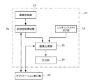
次に、本発明の実施の形態に係る画像処理装置10の制御部11の動作について説明する。この制御部11は、記憶部12に格納されたプログラムを実行することにより、図2に例示するように、機能的に、画像処理部51と、アプリケーション実行部52とを含み、画像処理部51は、画像取得部21と、仮想空間構成部23と、レンダリングカメラ設定部24と、画像生成部25と、出力部26とを含んで構成される。この画像処理部51は、アプリケーション実行部52から入力される指示に従って動作し、指定された視野内の仮想空間の像をレンダリングして得た一対の画像データ(左目用の画像データと右目用の画像データ)を立体視画像として生成する。
Next, the operation of the
画像取得部21は、表示装置40を装着したユーザの周囲の現実空間の情報を取得する。具体的にこの画像取得部21が取得する現実空間の情報は、表示装置40のカメラ43で撮像された画像データである。この例では、画像取得部21は、表示装置40から中継装置30を介して、カメラ43にて撮像した画像データを、現実空間の情報として受け入れる。本実施の形態の一例では、カメラ43で撮像した画像データは、左右に配した一対の撮像素子430で撮像された一対の画像データであり、各画像データの視差により撮像された現実空間内の対象物までの距離が判断できるものである。本実施の形態では、この画像取得部21は、カメラ43で撮像された画像データに基づいて、当該画像データ(以下区別のため撮像画像データと呼ぶ)と同じサイズ(同じ画素配列)のデプスマップを生成して出力する。ここでデプスマップは、カメラ43で撮像された画像データの各画素に撮像された対象物までの距離を表す情報を、当該画素に対応する画素の値とした画像データである。
The
仮想空間構成部23は、画像取得部21が出力するデプスマップの情報に基づいて、まず、環境メッシュリスト情報と、物体バッファとを生成する。ここで環境メッシュリスト情報は、例えば次のように求められる。
Based on the depth map information output from the
すなわち仮想空間構成部23は、デプスマップと、撮像画像データとを用いて、撮像画像データに撮像されている現実空間内の対象物を、対象物ごと(机、壁、床、本棚などの対象物ごと)に検出するセグメンテーション処理を行う。また仮想空間構成部23は、各対象物が占めるデプスマップ上の領域ごとに個別のラベル(オブジェクト識別子)を設定する。
That is, the virtual
仮想空間構成部23は、個別にラベルの付された領域内のデプスマップを参照して、当該領域内の対象物の外形状に沿ってメッシュ(ポリゴンメッシュ)を設定する。なお、ユーザが位置を変えたり、頭部を回転させて、カメラ43の視野が変化することで現実空間の対象物の形状が明らかになる場合がある(他の対象物によって隠蔽されていた部分が撮像されるなど)が、この場合は、当該対象物のメッシュを更新する。このようなメッシュの設定方法は例えば多視点の情報を用いるものなど、広く知られたものを採用できるので、ここでの詳しい説明を省略する。
The virtual
仮想空間構成部23は、環境メッシュリスト情報を生成する。この環境メッシュリスト情報には、設定された各メッシュの頂点座標(画素の位置を表す情報)と、メッシュの識別情報と、メッシュ内の画素に対応して撮像画像データ内の画素に撮像されている対象物の法線の情報と、メッシュの種類情報(予め定めた種類のいずれであるかを表す情報)と、メッシュの表面形状に関する情報と、メッシュに対応する対象物のオブジェクト識別子とが含まれる。なお、ここでメッシュの頂点座標は、ワールド座標系(現実空間中に設定され、床面内に互いに直行するξ軸,η軸をとり、鉛直方向をζ軸とする直交座標系)での値とすればよい。また、オブジェクト識別子はメッシュの識別情報に含まれていてもよい。
The virtual
このワールド座標系での値は、例えば、カメラ43が撮影して得た現実空間内の画像データに基づくユーザ座標系(XYZ座標系)で取得されたメッシュの頂点座標等の値を、座標変換情報としてのモデルビュー行列を用いて変換して得る。
The value in the world coordinate system is obtained by, for example, converting a value such as the vertex coordinate of the mesh acquired in the user coordinate system (XYZ coordinate system) based on the image data in the real space obtained by the
ここでメッシュの種類の情報は、メッシュ内の画素に対応する撮像画像データ内の画素に撮像された対象物の位置に基づいて生成される情報であり、床、天井、壁、障害物(床から所定の高さ以内にある壁以外の物体などとして予め定めておく)、その他のいずれであるかを表す。本実施の形態では、仮想空間構成部23は、対象物のワールド座標系(現実空間中に設定され、床面内に互いに直行するx軸,y軸をとり、鉛直方向をz軸とする直交座標系)で、z軸成分が最も小さい(もっとも低い位置にある)平面を床とする。また、z軸成分が最も大きい(もっとも高い位置にある)面を天井とする。さらに床に対して垂直な面であって、x軸またはy軸方向にもっとも遠い位置にある面を壁とする。その他の対象物は、障害物として分類する。
Here, the mesh type information is information generated based on the position of the object imaged on the pixel in the captured image data corresponding to the pixel in the mesh, and includes a floor, a ceiling, a wall, and an obstacle (floor It is determined in advance as an object other than a wall within a predetermined height from the above), or the other. In the present embodiment, the virtual
また、メッシュの表面形状に関する情報は、平面、凹凸のある面、球状の面、複雑な形状の面といった表面形状のいずれであるかを表す情報とする。この情報は、例えば対象物を表す各メッシュの法線の情報に基づいて定めることができる。 Further, the information regarding the surface shape of the mesh is information indicating whether the surface shape is a plane, an uneven surface, a spherical surface, or a complex surface. This information can be determined based on, for example, information on the normal line of each mesh representing the object.
このように、デプスマップの情報等から、撮像画像データ内の対象物の種類や、表面形状等を認識する方法には、種々のものがあるが、どのような方法を採用するかはここでは問わない。 As described above, there are various methods for recognizing the type of the object in the captured image data, the surface shape, and the like from the depth map information and the like. It doesn't matter.
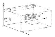
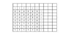
また物体バッファは、ユーザの位置と、ユーザの視野方向より後方とを含むユーザ周囲の所定サイズ(例えば幅(初期のユーザの視野方向に直交し、床面に平行な方向)10m、奥行(床面に平行な初期のユーザの視野方向)10m、高さ3mの直方体範囲)の現実空間(以下、対象空間と呼ぶ)を仮想的にボクセル(Voxel:仮想的な体積要素、例えば幅10cm,奥行10cm,高さ10cmの立方体要素)空間で表現したものであり、物体が存在するボクセルの値(ボクセル値)を「1」、存在しないボクセルの値を「0」、存在するか否かが不明なボクセルの値を「−1」と設定したものである(図4)。
The object buffer has a predetermined size (for example, a width (a direction perpendicular to the initial user's visual field direction and parallel to the floor surface) 10 m, a depth (floor), including the user's position and the rear of the user's visual field direction. A real space (hereinafter referred to as a target space) of 10 m and a 3 m high rectangular parallelepiped area parallel to the surface (virtual direction of the user) is virtually a voxel (Voxel: virtual volume element, for example,
図4では、図示の都合上、対象空間内の一部のボクセルのみを示し、またボクセルのサイズも説明のために適宜変更している。この対象空間に対するボクセルのサイズは、必ずしも実施時に適したものを示したものではない。また、図4では、対象空間の奥側隅に立方体状の物体Mが配され、その表面に相当するボクセルの値を、物体が存在することを表す「1」に設定し、表面から隠された部分のボクセルの値を、不明であることを表す「−1」とし、物体表面までの間にあるボクセルの値を、何もないことを表す「0」と設定する例を示している。 In FIG. 4, for the sake of illustration, only a part of the voxels in the target space is shown, and the size of the voxels is appropriately changed for explanation. The size of the voxel with respect to the target space does not necessarily indicate a size suitable for implementation. Also, in FIG. 4, a cubic object M is arranged at the back corner of the target space, and the value of the voxel corresponding to the surface is set to “1” indicating that the object exists, and is hidden from the surface. In this example, the value of the voxel in the part is set to “−1” indicating that it is unknown, and the value of the voxel existing up to the object surface is set to “0” indicating that there is nothing.
仮想空間構成部23は、デプスマップの情報に基づいてこのボクセル値を設定する。デプスマップ上の各画素は、デプスマップの元となった画像データの撮影時のカメラ43の位置座標(基準位置の座標でよい、以下撮影時位置と呼ぶ)を頂点とし、デプスマップの画角に相当する仮想的な四角錐の底辺を、デプスマップの解像度(縦py画素×横px画素)で分割したものである。そこで撮影時位置の座標を起点として各画素の頂点を通る線分に平行なベクトル(ワールド座標系での座標の差)や、撮影時位置の座標を起点として各画素の中心を通る線分に平行なベクトル(ワールド座標系での座標の差)が、撮影時位置の座標と、デプスマップの画角を表す情報と、デプスマップの解像度とから、各画素の方向として演算できる。
The virtual
そこで、仮想空間構成部23は、デプスマップ上の各画素について、撮影時位置の座標(基準位置の座標でよい)に対応する物体バッファ内の座標から当該画素の方向にあり、デプスマップが表す物体までの距離にあたるボクセルの値を「1」とし、当該ボクセルとは異なり、当該ボクセルからカメラ43までの線上にあるボクセルの値を「0」とする。また仮想空間構成部23は、カメラ43で撮像された画像データにおいて、現実空間内にある物体により隠され、撮像されていない部分(机や壁の裏、床に置かれた物の陰となっている部分)については、物体が存在するか否かが不明であるとして、対応する部分のボクセルの値を「−1」と設定する。
Therefore, the virtual
仮想空間構成部23は、ユーザが移動したり、頭部の向きを変えたりすることで、視点や視野方向が変更され、当該視点から当該視野方向に向いたカメラ43によって撮像された画像データに、過去に撮像されず、物体が存在するか否かが不明であったボクセルに対応する部分(値が「−1」であったボクセルに対応する部分)のデプスマップが得られたときには、当該部分のボクセルの値を、得られたデプスマップに基づいて「0」または「1」に設定して更新する。
The virtual
なお、デプスマップ等の情報から、このような物体の存在する範囲を表す三次元空間内のボクセル値を設定する方法は、ここで述べた方法のほか、3Dスキャンの方法で広く知られた方法等、種々の方法を採用できる。 A method for setting a voxel value in a three-dimensional space representing a range where such an object exists from information such as a depth map is a method widely known as a 3D scanning method in addition to the method described here. Various methods can be employed.
さらに仮想空間構成部23は、後に述べるレンダリングカメラ設定部24が対象空間内に設定した仮想的なレンダリングカメラの位置、及び視野に基づき、対象空間に対応するボクセル空間内に、当該仮想的なレンダリングカメラと同じ視野を設定したときの、当該視野内にあるボクセルの二次元投影像を生成する。
Furthermore, the virtual
つまり、このボクセルの二次元投影像は、レンダリング処理と同様、仮想的なレンダリングカメラの位置からレンダリングカメラの視野方向に予め定めた距離だけ離れた位置に、当該視野方向に直交し、設定された画角に対応するサイズを有する仮想的なスクリーンを配し、このスクリーン上に、画像生成部25が生成する立体視画像に含まれる画像データと同じサイズの画素配列を設定して、当該画素配列中の各画素を、次のように設定したものである。
That is, the two-dimensional projection image of the voxel is set at a position that is separated from the virtual rendering camera position by a predetermined distance in the rendering camera viewing direction, orthogonal to the viewing direction, as in the rendering process. A virtual screen having a size corresponding to the angle of view is arranged, and a pixel array having the same size as the image data included in the stereoscopic image generated by the
すなわち、仮想空間構成部23は、この画素配列中の各画素を順次選択し、仮想的なレンダリングカメラの位置から選択した画素の位置への線を延長した先にあるボクセルであって、最初にある「0」以外の値のボクセルの値を、選択した画素の画素値とする。ここで、「0」以外の値のボクセルがなければ、選択した画素の画素値を「0」とする。
That is, the virtual
これにより、例えば図5に示すような二次元投影像が得られることとなる。仮想空間構成部23は、この二次元投影像をアプリケーション実行部52に出力する。
Thereby, for example, a two-dimensional projection image as shown in FIG. 5 is obtained. The virtual
また、仮想空間構成部23は、後に説明するアプリケーション実行部52から入力される指示に従い、上記検出した現実空間内の対象物の位置(対象物に対応するメッシュの範囲)に対応する仮想空間内の位置に、仮想対象物を配した仮想空間の情報を生成することで、仮想空間を構成する。このように仮想空間内に、三次元モデルデータで表される仮想対象物を配する処理は、三次元グラフィックスを作成する際の処理において広く知られているので、ここでの詳しい説明を省略する。
In addition, the virtual
具体的な例として、この仮想空間構成部23は、アプリケーション実行部52から背景画像である背景画像データと、現実空間内の対象物を特定する情報(オブジェクト識別子)と、当該情報で特定される対象物の位置に対応する仮想空間内の位置に配されるべき物体の三次元モデルデータ及び当該物体の表面に適用するべきテクスチャ(マテリアル)のデータ等との入力を受け入れる。
As a specific example, the virtual
そして仮想空間構成部23は、入力されたオブジェクト識別子ごとに、当該オブジェクト識別子が表す対象物の外形を表すメッシュに外接する範囲に、オブジェクト識別子とともに入力された三次元モデルデータで表される仮想対象物を配置し、オブジェクト識別子とともに入力されたマテリアルの情報に対応するテクスチャ(予め設定しておく)を設定して、仮想空間を規定する情報を生成する。
Then, for each input object identifier, the virtual
レンダリングカメラ設定部24は、レンダリングを行う際の仮想的なレンダリングカメラの位置、視野方向(レンダリングカメラの向き)、及び、画角を設定する。本実施の形態では、このレンダリングカメラ設定部24は、例えばカメラ43に含まれる撮像素子430の位置によらず、予め定められた(例えばプログラムにハードコードされていてもよいし、設定ファイルに記述されたものを読取ったものであってもよい)レンダリングカメラの位置と、視野の方向を表す情報(例えばレンダリングカメラの位置を起点とし、視野の中心を通るベクトル情報)を得て、これらを視野の情報とする。
The rendering
またこのレンダリングカメラ設定部24は、別の例として、ユーザの動きに伴って時間変化する現実空間内の基準位置からの相対座標として仮想空間内のレンダリングカメラの位置を得てもよい。一つの例として、先に述べた基準位置から予め定めた相対座標値だけ移動した位置に対応する仮想空間内の位置を、レンダリングカメラの位置としてもよい。
As another example, the rendering
ここで相対座標は、例えば基準位置から撮像素子430Rまたは430Lの位置までの相対座標であってもよい。また相対座標は、基準位置から表示装置40を装着したユーザの右目(または左目)があるべき位置までの相対座標であってもよい。この場合、ユーザの右目(または左目)の位置に対応する仮想空間内の位置がレンダリングカメラの位置となる。
Here, the relative coordinates may be, for example, relative coordinates from the reference position to the position of the
具体的に、このレンダリングカメラ設定部24は、表示装置40を装着したユーザの頭部の位置(基準位置)及び頭部の向きを表す情報を、表示装置40が備える頭部方向センサ441から取得する。すなわち、レンダリングカメラ設定部24は、図3に例示するような、表示装置40の装着時の初期の方向からの床面に平行な面内での頭部方向の回転角度θと、仰角方向の回転角度φと、視野方向の軸まわりの回転角度ψと、頭部の移動量(x,y,z)を取得する。
Specifically, the rendering
レンダリングカメラ設定部24は、頭部の移動量の情報から、基準位置に対応する仮想空間内の座標を得る。現実空間のワールド座標と、仮想空間の座標とを一致させておき、現実空間の座標値をそのまま仮想空間の座標値として用いてもよい。レンダリングカメラ設定部24は、基準位置からユーザの右目の位置までの相対座標(予め設定しておく)を基準位置の座標値に加算して右目に対応するレンダリングカメラの位置を決定し、ユーザの頭部の向きをその視野方向とする。
The rendering
また、レンダリングカメラ設定部24は、基準位置からユーザの左目の位置までの相対座標(予め設定しておく)を基準位置の座標値に加算して左目に対応するレンダリングカメラの位置を決定し、ユーザの頭部の向きをその視野方向とする。なお、画角は予め定めておく。
Further, the rendering
画像生成部25は、レンダリングカメラ設定部24が設定した左目と右目とのそれぞれに対応するレンダリングカメラの位置及び視野方向、画角の情報を用い、仮想空間構成部23が生成した、仮想空間を規定する情報を参照して仮想空間内に配された仮想対象物の立体視画像(左目及び右目のそれぞれの画像データ)をレンダリングする。画像生成部25は、レンダリングして得られた一対の画像データを、立体視画像として出力部26に出力する。このレンダリングの方法は広く知られているので、ここでの詳しい説明を省略する。
The
出力部26は、画像生成部25から入力される立体視画像を、中継装置30を介して表示装置40へ出力する。
The output unit 26 outputs the stereoscopic image input from the
アプリケーション実行部52は、例えばゲームのプログラムを実行する。本実施の形態の例においてこのアプリケーション実行部52は、画像処理部51からボクセルの二次元投影像の情報の入力と、環境メッシュリスト情報との入力を受け入れる。
The
またアプリケーション実行部52は、ゲームの処理に従って、仮想空間に配置する仮想対象物の三次元モデルデータを決定する。具体的な例として、この決定の方法は次のようなものである。すなわち、ボクセルの値が「1」であって、対応する部分のメッシュについて、
(1)メッシュの種類が「天井」であれば、背景を合成する。
(2)メッシュの種類が障害物で、かつメッシュ表面形状が平面である物体は「操作パネル」とする。
(3)メッシュの種類が障害物で、かつメッシュ表面形状が凹凸のある面である物体は、「岩」または「箱」とする。
(4)メッシュの種類が障害物で、かつメッシュ表面形状が球状の物体は、「ライト」とする。
(5)メッシュの種類が障害物で、かつメッシュ表面形状が複雑な形状の物体は、「樹木,草木」とする。Moreover, the
(1) If the mesh type is “ceiling”, the background is synthesized.
(2) An object whose mesh type is an obstacle and whose mesh surface shape is a plane is an “operation panel”.
(3) An object whose mesh type is an obstacle and whose mesh surface shape is an uneven surface is a “rock” or “box”.
(4) An object whose type of mesh is an obstacle and whose mesh surface shape is spherical is called “light”.
(5) An object having a mesh type obstacle and a complicated mesh surface shape is defined as “tree, plant”.
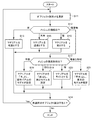
この例に基づくアプリケーション実行部52の動作を、図6を参照して説明する。図6に例示するように、アプリケーション実行部52は、入力された環境メッシュリスト情報を参照し、これまでに未選択のオブジェクト識別子を一つ選択する(S11)。
The operation of the
アプリケーション実行部52は、選択したオブジェクト識別子のメッシュの種類の情報を参照し(S12)、メッシュの種類が「床」であれば、選択したオブジェクト識別子に、マテリアルを地面とする設定を関連付けて(S13)、未選択のオブジェクト識別子があるか否かを判断し(S14)、未選択のオブジェクト識別子があれば、処理S11に戻って処理を続ける。
The
また、処理S12においてメッシュの種類が「天井」であれば、アプリケーション実行部52は、マテリアルを「透過」とする設定を関連付けて(S15、従って当該部分は背景画像が表示されることとなる)、処理S14に移行する。
In addition, if the mesh type is “ceiling” in the process S12, the
また処理S12において、メッシュの種類が「壁」であれば、アプリケーション実行部52は、マテリアルを「岩」とし、物体の三次元モデルデータとして「岩」のデータを用いるべき旨の設定を関連付けて(S16)、処理S14に移行する。さらに処理S12においてメッシュの種類が「障害物」である場合は、アプリケーション実行部52は、メッシュの表面形状の情報を参照し(S17)、表面形状が「平面」であれば、マテリアルを「木」とし、物体の三次元モデルデータとして「操作パネル」を用いるべき旨の設定を、選択されたオブジェクト識別子に関連付けて(S18)、処理S14に移行する。
If the mesh type is “wall” in process S12, the
また処理S17において、表面形状が「凹凸のある面」である場合は、アプリケーション実行部52は、マテリアルを「岩」とし、物体の三次元モデルデータとして「岩」のデータを用いるべき旨の設定を関連付けて(S19)、処理S14に移行する。処理S17において、表面形状が「球状」である場合は、アプリケーション実行部52は、マテリアルを「ライト」とする設定を関連付けて(S20)、処理S14に移行する。
Also, in the process S17, when the surface shape is “surface with unevenness”, the
さらに処理S17において、表面形状が「複雑な形状」である場合は、アプリケーション実行部52は、マテリアルを「草木」とし、物体の三次元モデルデータとして「草木」を用いるべき旨の設定を関連付けて(S21)、処理S14に移行する。
Further, in the process S17, when the surface shape is “complex shape”, the
処理S14において、未選択のオブジェクト識別子がない場合は、アプリケーション実行部52は処理を終了する。
If there is no unselected object identifier in process S14, the
この結果、得られたオブジェクト識別子ごとの三次元モデルデータとマテリアルの設定に基づき仮想空間構成部23が仮想空間を構成する。
As a result, the virtual
なお、ここでの処理は一例であって、ゲームの内容によっては、現実空間を撮像した画像に基づいて、現実空間内の物体について、当該物体と同じ形状、かつ同じ表面テクスチャを有する仮想対象物を、現実空間内の当該物体の位置に対応する仮想空間内の位置に配してもよい。この例では、ゲーム内でユーザの所在する現実空間の画像が仮想空間として再構成され、当該三次元空間内に配した、ユーザの目に対応する一対の仮想的なカメラ(ユーザの左右の目の位置にそれぞれ配され、ユーザの視野の方向を向いているカメラ)の視野内の画像がそれぞれレンダリングされて表示装置40にて表示されることとなる。
Note that the processing here is an example, and depending on the content of the game, a virtual object having the same shape and the same surface texture as the object for the object in the real space based on an image obtained by imaging the real space May be arranged at a position in the virtual space corresponding to the position of the object in the real space. In this example, an image of the real space where the user is located in the game is reconstructed as a virtual space, and a pair of virtual cameras (the left and right eyes of the user) arranged in the three-dimensional space and corresponding to the user's eyes. The images in the field of view of the camera that is arranged at the positions of the camera and facing the direction of the field of view of the user are respectively rendered and displayed on the
アプリケーション実行部52は、また、入力されたボクセルの二次元投影像を参照して、当該投影像中で「−1」となっている領域、つまり、現実空間内のうち対象物の検出を行っていない位置に対応する仮想空間内の位置に、予め定めた種類の視覚効果を与える仮想対象物を配してもよい。具体的にアプリケーション実行部52は、ボクセルの二次元投影像中で「−1」となっている領域を特定する情報(領域内の画素を特定する情報でよい)とともに、ゲームの処理として指定された映像効果または画像を表示する指示を、画像処理部51に出力してもよい。
The
ここで映像効果は、例えば煙のような映像を表示させるものや、光を点滅させているかのような映像効果などがある。また、表示する画像としては「?」のような画像であってもよいし、または注意・警戒を表す画像であってもよい。 Here, the video effect includes, for example, a video effect such as displaying a video like smoke or a video effect as if light is blinking. Further, the image to be displayed may be an image such as “?”, Or an image indicating caution / warning.
画像処理部51は、この指示を受けたときには、当該指示された範囲の画素に、指示された映像効果を合成し、あるいは指示された画像を合成して出力する。
When receiving this instruction, the
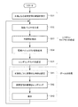
[動作]
本発明の実施の形態の画像処理装置10は以上の構成を基本的に備えており、次のように動作する。ユーザが表示装置40を頭部に装着すると、画像処理装置10は、図7に例示する処理を開始し、ワールド座標系を設定する。[Operation]
The
そして表示装置40の所定位置(例えばカメラ43の各撮像素子430の重心位置)を原点として、ユーザの初期の視線方向より後方を含むユーザ周囲のX軸方向に±5m(合計10m)、Y軸方向に±5m(合計10m)、Z軸方向に床から高さ3mの直方体範囲の現実空間を対象空間として設定する(S31)。 Then, with the predetermined position of the display device 40 (for example, the position of the center of gravity of each imaging device 430 of the camera 43) as the origin, ± 5 m (total 10 m) in the X axis direction around the user including the rear from the user's initial line-of-sight direction, Y axis A real space in a rectangular parallelepiped range of ± 5 m in the direction (total 10 m) and 3 m in height from the floor in the Z-axis direction is set as the target space (S31).
そしてこの対象空間を、仮想的にボクセル(Voxel:仮想的な体積要素、例えば幅10cm,奥行10cm,高さ10cmの立方体要素)空間で表現した物体バッファ(当初はすべてのボクセルの値を「−1」と設定する)を設定して、記憶部12に格納する(S32)。 This object space is represented by an object buffer (initially, all the voxel values are represented by “−”. 1 ”is set and stored in the storage unit 12 (S32).
表示装置40は、所定のタイミングごと(例えば1/1000秒ごと)に繰り返してカメラ43よって画像を撮像し、撮像して得た撮像画像データを画像処理装置10へ送出している。画像処理装置10は表示装置40から中継装置30を介して、撮像画像データを受け入れる。そして画像処理装置10は、この撮像画像データに基づいて、当該画像データから得られるデプスマップを生成する。
The
画像処理装置10は、生成したデプスマップを用いて、現実空間内の対象物(天井、床、壁、家具類など)を検出する(S33)。また画像処理装置10は、検出した対象物の形状を表すメッシュ(ポリゴンメッシュ)の種類や表面形状を判断し、生成したメッシュの位置を表す情報(メッシュの頂点の座標でよい)と、メッシュの種類の情報と、表面形状の情報とを関連付けて、環境メッシュリスト情報として記憶部12に格納する(S34:環境メッシュリスト情報生成)。
The
画像処理装置10は、センサ44によりユーザの頭部の移動や頭部の向きを検出し、当該検出した頭部の移動や向きの情報に基づいてレンダリングカメラの位置と視野とを設定する(S35)。
The
画像処理装置10はさらに、デプスマップ内の各画素を順次選択しつつ、センサ44により検出されたユーザの頭部の移動に基づき、基準位置のワールド座標系中の位置座標を得る。そして、当該取得した位置座標に対応する位置に対応する物体バッファ中の座標からデプスマップの選択した画素が表す物体までの距離にあたるボクセルの値を「1」とし、当該ボクセルとは異なり、当該ボクセルからカメラ43までの線上にあるボクセルの値を「0」とする。ここで、カメラ43で撮像された画像データにおいて、現実空間内にある物体により隠され、撮像されていない部分については、物体が存在するか否かが不明であるとして、対応する部分のボクセルの値が「−1」のままとなる。
The
なお、画像処理装置10は、ユーザが移動したり、頭部の向きを変えたりすることで、カメラ43によって撮像された画像データに、過去に撮像されず、物体が存在するか否かが不明であったボクセルに対応する部分(値が「−1」であったボクセルに対応する部分)のデプスマップが得られたときには、処理S11において当該部分のボクセルの値を、得られたデプスマップに基づいて「0」または「1」に設定して更新する。
It should be noted that the
画像処理装置10は、レンダリングカメラの位置座標から、物体バッファ中でカメラ43の視野方向にあるボクセルを二次元投影した投影像を生成する(図5)。
The
画像処理装置10は、また、ゲームの処理として、環境メッシュリスト情報や、ボクセルの二次元投影像の情報を参照して次の処理を行う。
The
すなわち、画像処理装置10は、環境メッシュリスト情報を参照して、検出されている対象物ごとに、そのメッシュの種類や表面形状の情報に基づき、対象物の存在する現実空間に対応する仮想空間内の領域に、対応させる仮想対象物を配して、仮想空間を構成する(S41)。なお、仮想空間の構成に用いる背景画像や、仮想対象物の三次元モデルデータ等は、ゲームのデータとしてゲームの提供者により用意されているものを用いればよい。
That is, the
一例として、平坦な床面上に机と、本棚と、テレビ台、テレビなどが置かれ、四方を壁に囲まれている室内に表示装置40を装着したユーザが所在している場合、机の天板が、表面形状が平面である障害物のメッシュと判断される。そこで画像処理装置10は、この天板のある位置に、例えば「操作パネル」の仮想対象物を配する設定を行う。また、壁については、壁の表面の位置に、「岩」として視認される仮想対象物の表面が位置するよう、仮想的な岩を配する、といった設定を行う。また天井に相当する範囲については、透明なマテリアルであるとして、背景画像を合成するよう設定して、あたかも天井がないかのような仮想空間を構成する。
As an example, when a desk, a bookshelf, a TV stand, a TV, etc. are placed on a flat floor, and a user wearing the
そして画像処理装置10は、ここで構成した仮想空間を、処理S35で設定したレンダリングカメラの位置から、設定された視野の範囲を見たときの仮想的な立体視画像を、レンダリング処理により作成する(S42)。またこのとき、物体バッファのボクセルを二次元投影した投影像に基づき、物体の有無が不明である部分について所定の映像効果(煙を立てるなど)を設定してもよい。画像処理装置10は、こうして生成した立体視画像のデータを、表示装置40へ送出して、立体視画像を表示させる(S43)。
Then, the
以下、ユーザが移動したり、頭部を動かしてカメラ43の位置や視野方向が変化すると、新たに撮像画像データに撮像された画像に基づいて、ボクセル空間の情報や環境メッシュリスト情報が更新される。またユーザの頭部の位置及び方向によりレンダリングカメラの位置及び視野を設定している場合は、レンダリングカメラの位置及び視野も更新される。そして画像処理装置10は、この更新された情報を参照してレンダリングの処理を行って、立体視画像のデータを更新して表示させる。
Hereinafter, when the user moves or moves the head to change the position and field of view of the
また画像処理装置10は、ゲームの処理として、ユーザが机の天板に対応する仮想的な空間内の位置にある仮想的な操作パネルに触れると、操作パネルに対する操作を受け入れる処理を実行する。このときユーザは、仮想空間内で操作パネルの位置に手を伸ばせば、現実空間における机の天板に触れることとなるので、触覚的なフィードバックも得ることができる。またユーザが、机の天板がある範囲まで移動しようとすることがなくなる(操作パネルが表示されているため、操作パネルを押しのけるような移動をしなくなる)など、周囲に存在する障害物の位置をゲーム上の処理において自然に感得させることが可能となる。
Further, as a game process, the
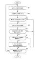
[手の届かない範囲の対象物]
ここで画像処理装置10は、ユーザからの距離によらず、対象空間内の対象物については対応する仮装対象物を表示するよう処理を行うこととして説明したが、本実施の形態は、このような場合に限られず、ユーザから所定の距離(例えば、ユーザ座標系において、Z軸の値(カメラからの距離)を用いる)の範囲内にある対象物の位置を検出し、当該検出した各対象物の位置に対応する仮想空間内の位置に、仮想対象物を配して仮想的な空間の情報を構成することとしてもよい。[Objects that are out of reach]
Here, the
具体的にこの例では画像処理装置10は、ゲームの処理などにおいて、図8に例示するように、これまでに未選択のオブジェクト識別子を一つ選択し(S51)、選択したオブジェクト識別子に対応するメッシュまでの距離(対応するメッシュの頂点のうち、その座標情報とレンダリングカメラの位置との距離が最小のもの)を求める(S52)。
Specifically, in this example, the
そして求めた距離が予め定めた第1のしきい値を超えるか否かを判断し(S53)、この第1のしきい値を超える場合には(Yesの場合には)、当該メッシュに対応する仮想対象物を表示しないこととして、さらに未選択のオブジェクト識別子があるか否かを判断し(S54)、未選択のオブジェクト識別子があれば、処理S51に戻って処理を続ける。 Then, it is determined whether or not the obtained distance exceeds a predetermined first threshold value (S53). If this distance exceeds the first threshold value (if Yes), it corresponds to the mesh. The virtual object to be displayed is not displayed, and it is further determined whether or not there is an unselected object identifier (S54). If there is an unselected object identifier, the process returns to step S51 to continue the process.
一方、処理S53において、処理S52にて求めた距離が上記第1のしきい値を超えていない場合には(Noの場合には)、画像処理装置10は、図6に例示した処理のうち処理S12から処理S21までの処理を実行して、オブジェクト識別子ごとに、対応する仮想対象物のマテリアルや三次元モデルデータを決定する(S55)。なお、図6の処理における処理S14は次の処理S56への移行とする。
On the other hand, in the process S53, when the distance obtained in the process S52 does not exceed the first threshold value (in the case of No), the
次に画像処理装置10は、処理S52にて求めた距離が予め定めた第2のしきい値(第1のしきい値より小さい値とする)を超えるか否かを判断する(S56)。ここで上記距離が第2のしきい値を超えると判断された場合(Yesの場合)は、選択したオブジェクト識別子に対応するメッシュの種類の情報を参照して、当該種類の情報が「障害物」であるか否かを判断する(S57)。
Next, the
ここでメッシュの種類が「障害物」でなければ(つまり、天井、床、壁であれば)、画像処理装置10は処理S54に移行する。また、メッシュの種類が「障害物」であれば、画像処理装置10は、ゲームの処理に応じて、選択しているオブジェクト識別子に対応する仮想対象物の位置を、時間とともに移動するように設定してもよい(S58)。
If the mesh type is not “obstacle” (that is, if it is a ceiling, floor, or wall), the
例えば、ここでの第2のしきい値を、ユーザの手が到達する範囲の限界を表す値として設定し、この第2のしきい値を超える位置にある仮想対象物については、ユーザの手の届かない範囲を動き回るロボットとして設定してもよい。またこの可動範囲は、処理S52で求めた距離と、第2のしきい値との差によって定めてもよい。 For example, the second threshold value here is set as a value representing the limit of the range that the user's hand reaches, and the virtual object located at a position exceeding the second threshold value is set to the user's hand. It may be set as a robot that moves around in a range that cannot be reached. The movable range may be determined by the difference between the distance obtained in step S52 and the second threshold value.
具体的には、当該差が小さくなるほど、可動範囲が、仮想対象物が仮想空間内で本来あるべき位置に近接した範囲となるよう制御してもよい。ここで本来あるべき位置とは、例えば当該仮想対象物に対応する現実空間内の対象物の位置に対応する仮想空間上の位置である。つまり、この例では、ユーザが手の届く位置に移動した場合には当該仮想対象物に対応する現実空間内の対象物の位置に対応する仮想空間の位置に戻っているよう制御される。その後、画像処理装置10は、処理S54に移行して処理を続ける。
Specifically, as the difference becomes smaller, the movable range may be controlled to be a range closer to the position where the virtual object is supposed to be in the virtual space. Here, the original position is, for example, a position on the virtual space corresponding to the position of the object in the real space corresponding to the virtual object. That is, in this example, when the user moves to a position where the user can reach, control is performed so as to return to the position of the virtual space corresponding to the position of the object in the real space corresponding to the virtual object. Thereafter, the
また画像処理装置10は、処理S56において、処理S52にて求めた距離が予め定めた第2のしきい値を超えない場合は、処理S54に移行する。これにより、第2のしきい値を超えない位置にある対象物については、当該対象物の位置に対応する仮想空間上の位置に、対象物に対応するマテリアルの仮想対象物が配置されることとなる。
If the distance obtained in step S52 does not exceed the predetermined second threshold value in step S56, the
本実施の形態のこの例では、ユーザの手に届くところにある現実空間内の対象物は、仮想空間内の仮想対象物として反映させる一方、ユーザの手が届かないところの現実空間内の対象物については、動かしたり、仮想対象物として表示することを省略したりするなどして、自由度の高い表示を行わせる。また仮想対象物を動かす場合であっても、その仮想対象物に対応する現実空間内の対象物とユーザとの現実空間上での距離に応じて動かすことのできる範囲(可動範囲)を制御することで、ユーザが近くへ来たときには、もとの位置に戻るように制御される。 In this example of the present embodiment, an object in the real space that can reach the user's hand is reflected as a virtual object in the virtual space, while an object in the real space that cannot be reached by the user's hand. An object is displayed with a high degree of freedom by moving or omitting display as a virtual object. In addition, even when moving a virtual object, the range (movable range) that can be moved according to the distance between the object in the real space corresponding to the virtual object and the user in the real space is controlled. Thus, when the user comes close, the control is performed so as to return to the original position.
[現実空間で動いている対象物]
また本実施の形態の画像処理装置10は、撮像画像データ内で少なくとも続けて所定回数(複数回数とする)だけ同じ位置にある対象物についてのみ、現実空間内の対象物として検出するようにしてもよい。例えばユーザの手などが撮像画像データに含まれる場合であっても、手については一般に動いてしまうものであるので、現実空間の対象物として検出しない。また、ユーザの眼前を横切る他の人物などについても同様である。[Object moving in real space]
In addition, the
[段差]
さらに本実施の形態の画像処理装置10は、メッシュの種類が「床」と判断されたメッシュに、段差があると検出したときには、当該段差の位置に対応する仮想空間内の位置に、「注意!」のような情報を表示する処理を行ってもよい。[Step]
Furthermore, when the
[カメラシースルーとの切替え]
また本実施の形態の画像処理装置10は、ユーザの指示により、仮想空間内の仮想対象物等をレンダリングして得た立体視画像に代えて、カメラ43が撮像した現実空間の撮像画像データに基づいて、現実空間の立体視画像を生成して出力することとしてもよい(いわゆるカメラシースルー)。[Switching to camera see-through]
Further, the
例えば本実施の形態の画像処理装置10は、ユーザがゲームの一時停止を指示する操作デバイス20上のポーズボタンを押下したときに、ゲームの処理を中断するとともに、カメラシースルーの表示に切り替えてもよい。
For example, the
この場合、ゲームを再開する指示が行われると(例えば操作デバイス20上のポーズボタンを再度押下する操作が行われると)、画像処理装置10は、仮想空間の立体視画像を表示する処理を再開し、ゲームの処理を再開してもよい。
In this case, when an instruction to resume the game is issued (for example, when an operation of pressing the pause button on the
さらに、画像処理装置10は、ゲームオーバーの際など、ゲームが終了したときにはユーザの明示の指示によらずにカメラシースルーの表示に切り替えてもよい。
Furthermore, the
この切替えの際には、仮想空間の立体視画像と、撮像画像データに基づく立体視画像とを瞬時に切替えることとしてもよいし、クロスフェードなど、既知の画面切替えの映像を生成して表示する処理を行ってもよい。 At the time of this switching, a stereoscopic image in the virtual space and a stereoscopic image based on the captured image data may be switched instantaneously, or a known screen switching video such as a crossfade is generated and displayed. Processing may be performed.
[ゲームの処理上、必要な面がない場合の処理]
また本実施の形態では、ゲームなどの処理の都合上、配置すべき仮想対象物の三次元モデルに対応する種類・表面形状のメッシュが存在しない場合、画像処理装置10はその旨、ユーザに通知してもよい。[Processing when there are no required aspects for game processing]
In this embodiment, if there is no mesh of a type / surface shape corresponding to the three-dimensional model of the virtual object to be placed for the convenience of processing such as a game, the
この例では具体的に、仮想対象物の三次元モデルのデータを、仮想空間内に必ず配置するべき仮想対象物の三次元モデルのデータであるか、または、配置してもよい(配置するか否かが任意な)仮想対象物の三次元モデルのデータであるかを表す情報(必須性情報)に関連付けておく。 Specifically, in this example, the data of the three-dimensional model of the virtual object is the data of the three-dimensional model of the virtual object that should always be arranged in the virtual space, or may be arranged (whether the data is arranged) It is associated with information (essentiality information) indicating whether or not the data is a three-dimensional model of a virtual object.
そして図6の処理(または図8において図6の処理に相当する処理)が完了した後に、必須性情報により配置が必須とされている仮想対象物の三次元モデルのデータのすべてが、いずれかのオブジェクト識別子に関連付けられているか否かを調べる。ここで、オブジェクト識別子に関連付けられていない、配置が必須とされている仮想対象物の三次元モデルのデータがあった場合、画像処理装置10は、ユーザに対して、その旨を報知する画像を生成して、表示装置40に送出してもよい。
Then, after the process of FIG. 6 (or the process corresponding to the process of FIG. 6 in FIG. 8) is completed, all of the data of the three-dimensional model of the virtual object whose arrangement is indispensable according to the essentiality information is either It is checked whether it is associated with the object identifier. Here, when there is data of a three-dimensional model of a virtual object that is not necessarily associated with an object identifier and is required to be arranged, the
[変形例]
ここまでの例によると、レンダリングカメラの位置は、例えばユーザの実際の目の位置に設定される。この場合、ユーザの目から仮想空間内での手までの距離感が補正されて違和感が低減される。[Modification]
According to the examples so far, the position of the rendering camera is set to, for example, the actual eye position of the user. In this case, the sense of distance from the user's eyes to the hand in the virtual space is corrected, and the uncomfortable feeling is reduced.
また本実施の形態のここまでの説明では、撮像画像データがカメラ43によって得られるものとしたが、本実施の形態はこれに限られない。本実施の形態の別の例として、ユーザの所在する室内に配置されたカメラによって撮像されたものであっても構わない。
In the above description of the present embodiment, the captured image data is obtained by the
さらに本実施の形態では、現実空間内の対象物の情報が得られればどのような方法でもよく、例えば現実空間を、ゲームの処理開始前に対象空間内の対象物を3Dスキャニングしておいてもよいし、赤外線で所定の光パターンを照射して、当該パターンを認識することで対象空間内の対象物の外形状を認識してもよい。 Furthermore, in the present embodiment, any method may be used as long as the information on the object in the real space can be obtained. For example, the object in the target space is scanned in 3D before the game processing is started. Alternatively, the outer shape of the object in the target space may be recognized by irradiating a predetermined light pattern with infrared rays and recognizing the pattern.
[ユーザの頭部の位置及び傾きの情報を取得する別の例]
また上述の説明では、ユーザの頭部の位置及び傾きの情報は、表示装置40に設けられた頭部方向センサ441から得られるものとしていたが、本実施の形態はこれに限られず、例えば、ユーザの所在する室内の既知の位置に配置されたカメラによってユーザを撮像し、ユーザの頭部とともに移動する所定の点、例えばユーザが装着している表示装置40上に予め配した所定のマーカーの位置及び姿勢を検出することで、ユーザの頭部の位置及び傾き角度を検出してもよい。このようなマーカーとそれを撮像した画像データに基づく、マーカーの位置及び傾きを検出する技術は広く知られているので、ここでの詳しい説明は省略する。[Another example of acquiring information on the position and tilt of the user's head]
In the above description, the information on the position and inclination of the user's head is assumed to be obtained from the
この方法でユーザの頭部の位置及び傾きの情報を取得する場合、表示装置40には頭部方向センサ441を設ける必要は必ずしもない。
When acquiring information on the position and tilt of the user's head by this method, the
[実施形態の効果]
本発明の実施の形態によると、ユーザに対して仮想空間の画像を、現実空間との関係で違和感を生じさせることなく表示できる。[Effect of the embodiment]
According to the embodiment of the present invention, a virtual space image can be displayed to the user without causing a sense of incongruity in relation to the real space.
10 画像処理装置、11 制御部、12 記憶部、13 インタフェース部、20 操作デバイス、21 画像取得部、23 仮想空間構成部、24 レンダリングカメラ設定部、25 画像生成部、26 出力部、30 中継装置、40 表示装置、41 映像表示素子、42 光学素子、43 カメラ、44 センサ、45 通信インタフェース、51 画像処理部、52 アプリケーション実行部、430 撮像素子、441 頭部方向センサ
DESCRIPTION OF
Claims (7)
当該ユーザの周囲の現実空間の情報を取得する情報取得手段と、
前記取得した現実空間の情報に基づいて、当該現実空間内の対象物の位置を検出し、当該検出した各対象物の位置に対応する仮想空間内の位置に、仮想的な物体を配して仮想空間の情報を構成する仮想空間構成手段と、
前記仮想空間構成手段により構成された仮想空間の画像を生成する画像生成手段と、
前記画像生成手段が生成した画像を、前記表示装置に出力する出力手段と、
を含む画像処理装置。An image processing device connected to a display device used by a user wearing on the head,
Information acquisition means for acquiring information on the real space around the user;
Based on the acquired information on the real space, the position of the target object in the real space is detected, and a virtual object is arranged at a position in the virtual space corresponding to the detected position of each target object. Virtual space configuration means for configuring virtual space information;
Image generating means for generating an image of the virtual space configured by the virtual space forming means;
Output means for outputting the image generated by the image generation means to the display device;
An image processing apparatus.
前記仮想空間設定手段は、前記現実空間内の対象物の表面形状をさらに識別し、当該識別された表面形状の情報に基づいて、当該対象物の位置に対応する仮想空間内の位置に配する仮想的な物体を決定する画像処理装置。The image processing apparatus according to claim 1,
The virtual space setting means further identifies the surface shape of the object in the real space, and places the object on the position in the virtual space corresponding to the position of the object based on the information on the identified surface shape. An image processing apparatus that determines a virtual object.
前記仮想空間設定手段は、前記現実空間内の対象物の位置の情報に基づいて、当該対象物の位置に対応する仮想空間内の位置に配する仮想的な物体を決定する画像処理装置。The image processing apparatus according to claim 1 or 2,
The virtual space setting unit is an image processing apparatus that determines a virtual object to be placed at a position in a virtual space corresponding to the position of the target object based on information on the position of the target object in the real space.
前記情報取得手段が取得する現実空間の情報は、現実空間を撮像して得た画像情報であり、
ユーザの指示に基づいて、前記出力手段が、前記取得した現実空間の画像情報に基づく画像を前記表示装置に出力するか、前記画像生成手段が生成した仮想空間の画像を、前記表示装置に出力するかを選択する画像処理装置。The image processing apparatus according to any one of claims 1 to 3,
The real space information acquired by the information acquisition means is image information obtained by imaging the real space,
Based on a user instruction, the output unit outputs an image based on the acquired real space image information to the display device, or outputs an image of the virtual space generated by the image generation unit to the display device. An image processing apparatus that selects whether to do.
前記仮想空間構成手段は、現実空間内のうち対象物の検出を行っていない位置に対応する仮想空間内の位置に、予め定めた種類の視覚効果を与える仮想対象物を配して仮想空間を構成する画像処理装置。The image processing apparatus according to any one of claims 1 to 4, wherein:
The virtual space composing means arranges a virtual object that gives a predetermined type of visual effect at a position in the virtual space corresponding to a position in the real space where the object is not detected. The image processing apparatus which comprises.
前記仮想空間構成手段は、当該現実空間内の対象物のうち、ユーザから所定の距離の範囲内にある対象物の位置を検出し、当該検出した各対象物の位置に対応する仮想空間内の位置に、仮想的な物体を配して仮想的な空間の情報を構成する画像処理装置。An image processing apparatus according to any one of claims 1 to 5,
The virtual space constituting unit detects a position of an object within a predetermined distance from a user among objects in the real space, and in the virtual space corresponding to the detected position of each object. An image processing apparatus that configures virtual space information by arranging virtual objects at positions.
当該ユーザの周囲の現実空間の情報を取得する情報取得手段と、
前記取得した現実空間の情報に基づいて、当該現実空間内の対象物の位置を検出し、当該検出した各対象物の位置に対応する仮想空間内の位置に、仮想的な物体を配して仮想空間の情報を構成する仮想空間構成手段と、
前記仮想空間構成手段により構成された仮想空間の画像を生成する画像生成手段と、
前記画像生成手段が生成した画像を、前記表示装置に出力する出力手段と、
として機能させるプログラム。An image processing device connected to a display device used by the user wearing on the head,
Information acquisition means for acquiring information on the real space around the user;
Based on the acquired information on the real space, the position of the target object in the real space is detected, and a virtual object is arranged at a position in the virtual space corresponding to the detected position of each target object. Virtual space configuration means for configuring virtual space information;
Image generating means for generating an image of the virtual space configured by the virtual space forming means;
Output means for outputting the image generated by the image generation means to the display device;
Program to function as.
Applications Claiming Priority (3)
| Application Number | Priority Date | Filing Date | Title |
|---|---|---|---|
| JP2016092560 | 2016-05-02 | ||
| JP2016092560 | 2016-05-02 | ||
| PCT/JP2017/005741 WO2017191702A1 (en) | 2016-05-02 | 2017-02-16 | Image processing device |
Publications (2)
| Publication Number | Publication Date |
|---|---|
| JPWO2017191702A1 true JPWO2017191702A1 (en) | 2018-11-22 |
| JP6682624B2 JP6682624B2 (en) | 2020-04-15 |
Family
ID=60202879
Family Applications (1)
| Application Number | Title | Priority Date | Filing Date |
|---|---|---|---|
| JP2018515395A Active JP6682624B2 (en) | 2016-05-02 | 2017-02-16 | Image processing device |
Country Status (4)
| Country | Link |
|---|---|
| US (1) | US10540825B2 (en) |
| EP (1) | EP3454304A4 (en) |
| JP (1) | JP6682624B2 (en) |
| WO (1) | WO2017191702A1 (en) |
Families Citing this family (3)
| Publication number | Priority date | Publication date | Assignee | Title |
|---|---|---|---|---|
| GB201707294D0 (en) * | 2017-05-08 | 2017-06-21 | Rajab Khalid | Nodens |
| JPWO2023032316A1 (en) * | 2021-08-31 | 2023-03-09 | ||
| WO2023032334A1 (en) * | 2021-08-31 | 2023-03-09 | ソニーグループ株式会社 | Information processing device, information processing method, and program |
Citations (6)
| Publication number | Priority date | Publication date | Assignee | Title |
|---|---|---|---|---|
| JP2011229679A (en) * | 2010-04-27 | 2011-11-17 | Senyo Kogyo Kk | Ferris wheel |
| JP2012133471A (en) * | 2010-12-20 | 2012-07-12 | Kokusai Kogyo Co Ltd | Image composer, image composition program and image composition system |
| JP2012155655A (en) * | 2011-01-28 | 2012-08-16 | Sony Corp | Information processing device, notification method, and program |
| JP2015143976A (en) * | 2013-12-25 | 2015-08-06 | キヤノンマーケティングジャパン株式会社 | Information processing device, method for controlling the same, and program |
| WO2016048658A1 (en) * | 2014-09-25 | 2016-03-31 | Pcms Holdings, Inc. | System and method for automated visual content creation |
| JP2016058042A (en) * | 2014-09-12 | 2016-04-21 | キヤノン株式会社 | Information processing apparatus, information processing method, and program |
Family Cites Families (7)
| Publication number | Priority date | Publication date | Assignee | Title |
|---|---|---|---|---|
| JP5646263B2 (en) | 2010-09-27 | 2014-12-24 | 任天堂株式会社 | Image processing program, image processing apparatus, image processing system, and image processing method |
| US9041622B2 (en) * | 2012-06-12 | 2015-05-26 | Microsoft Technology Licensing, Llc | Controlling a virtual object with a real controller device |
| JP5580855B2 (en) * | 2012-06-12 | 2014-08-27 | 株式会社ソニー・コンピュータエンタテインメント | Obstacle avoidance device and obstacle avoidance method |
| US9619911B2 (en) * | 2012-11-13 | 2017-04-11 | Qualcomm Incorporated | Modifying virtual object display properties |
| JP6281495B2 (en) | 2013-02-01 | 2018-02-21 | ソニー株式会社 | Information processing apparatus, terminal apparatus, information processing method, and program |
| JP2015125641A (en) | 2013-12-26 | 2015-07-06 | キヤノンマーケティングジャパン株式会社 | Information processing device, control method therefor, and program |
| JP5913709B1 (en) | 2015-09-29 | 2016-04-27 | 株式会社コロプラ | Image generation apparatus, image generation method, and image generation program |
-
2017
- 2017-02-16 EP EP17792635.9A patent/EP3454304A4/en not_active Ceased
- 2017-02-16 WO PCT/JP2017/005741 patent/WO2017191702A1/en unknown
- 2017-02-16 JP JP2018515395A patent/JP6682624B2/en active Active
- 2017-02-16 US US16/093,252 patent/US10540825B2/en active Active
Patent Citations (6)
| Publication number | Priority date | Publication date | Assignee | Title |
|---|---|---|---|---|
| JP2011229679A (en) * | 2010-04-27 | 2011-11-17 | Senyo Kogyo Kk | Ferris wheel |
| JP2012133471A (en) * | 2010-12-20 | 2012-07-12 | Kokusai Kogyo Co Ltd | Image composer, image composition program and image composition system |
| JP2012155655A (en) * | 2011-01-28 | 2012-08-16 | Sony Corp | Information processing device, notification method, and program |
| JP2015143976A (en) * | 2013-12-25 | 2015-08-06 | キヤノンマーケティングジャパン株式会社 | Information processing device, method for controlling the same, and program |
| JP2016058042A (en) * | 2014-09-12 | 2016-04-21 | キヤノン株式会社 | Information processing apparatus, information processing method, and program |
| WO2016048658A1 (en) * | 2014-09-25 | 2016-03-31 | Pcms Holdings, Inc. | System and method for automated visual content creation |
Non-Patent Citations (1)
| Title |
|---|
| 大島登志一, 外3名: ""RV−Border Guards:複数人参加型複合現実感ゲーム"", 日本バーチャルリアリティ学会論文誌, vol. 第4巻, 第4号, JPN6019027830, 31 December 1999 (1999-12-31), JP, pages 699 - 705, ISSN: 0004079790 * |
Also Published As
| Publication number | Publication date |
|---|---|
| EP3454304A4 (en) | 2019-12-18 |
| JP6682624B2 (en) | 2020-04-15 |
| US20190206142A1 (en) | 2019-07-04 |
| US10540825B2 (en) | 2020-01-21 |
| WO2017191702A1 (en) | 2017-11-09 |
| EP3454304A1 (en) | 2019-03-13 |
Similar Documents
| Publication | Publication Date | Title |
|---|---|---|
| JP6933727B2 (en) | Image processing equipment, image processing methods, and programs | |
| CN110022470B (en) | Method and system for training object detection algorithm using composite image and storage medium | |
| KR20210154814A (en) | Head-mounted display with pass-through imaging | |
| US20180315364A1 (en) | Information Processing Apparatus and Image Generation Method | |
| US10999412B2 (en) | Sharing mediated reality content | |
| JP2017142569A (en) | Method and program for providing head-mounted display with virtual space image | |
| CN112041788B (en) | Selecting text input fields using eye gaze | |
| JP7182920B2 (en) | Image processing device, image processing method and program | |
| JP2013174642A (en) | Image display device | |
| KR102386764B1 (en) | Virtual/augmented reality system with dynamic local resolution | |
| EP3688985A1 (en) | Head-mountable display system | |
| JP2015084002A (en) | Mirror display system and image display method thereof | |
| JPWO2017022291A1 (en) | Information processing device | |
| JPWO2019198784A1 (en) | Light field image generation system, image display system, shape information acquisition server, image generation server, display device, light field image generation method and image display method | |
| WO2017191702A1 (en) | Image processing device | |
| JP6963399B2 (en) | Program, recording medium, image generator, image generation method | |
| JP6687751B2 (en) | Image display system, image display device, control method thereof, and program | |
| JP6591667B2 (en) | Image processing system, image processing apparatus, and program | |
| EP3679453A1 (en) | A method of modifying an image on a computational device | |
| WO2017191703A1 (en) | Image processing device | |
| JP2019032713A (en) | Information processing device, information processing method, and program | |
| JP2017069924A (en) | Image display device | |
| JP2020106587A (en) | Head mount display, method for display, and display system | |
| JP6613099B2 (en) | Program, computer and head-mounted display system for stereoscopic display of virtual reality space | |
| JP2017142769A (en) | Method and program for providing head-mounted display with virtual space image |
Legal Events
| Date | Code | Title | Description |
|---|---|---|---|
| A621 | Written request for application examination |
Free format text: JAPANESE INTERMEDIATE CODE: A621 Effective date: 20180613 |
|
| A131 | Notification of reasons for refusal |
Free format text: JAPANESE INTERMEDIATE CODE: A131 Effective date: 20190723 |
|
| A521 | Request for written amendment filed |
Free format text: JAPANESE INTERMEDIATE CODE: A523 Effective date: 20190920 |
|
| A02 | Decision of refusal |
Free format text: JAPANESE INTERMEDIATE CODE: A02 Effective date: 20191126 |
|
| A521 | Request for written amendment filed |
Free format text: JAPANESE INTERMEDIATE CODE: A523 Effective date: 20200205 |
|
| A911 | Transfer to examiner for re-examination before appeal (zenchi) |
Free format text: JAPANESE INTERMEDIATE CODE: A911 Effective date: 20200217 |
|
| TRDD | Decision of grant or rejection written | ||
| A01 | Written decision to grant a patent or to grant a registration (utility model) |
Free format text: JAPANESE INTERMEDIATE CODE: A01 Effective date: 20200303 |
|
| A61 | First payment of annual fees (during grant procedure) |
Free format text: JAPANESE INTERMEDIATE CODE: A61 Effective date: 20200325 |
|
| R150 | Certificate of patent or registration of utility model |
Ref document number: 6682624 Country of ref document: JP Free format text: JAPANESE INTERMEDIATE CODE: R150 |