JPWO2006019016A1 - Backlight device and color liquid crystal display device - Google Patents
Backlight device and color liquid crystal display device Download PDFInfo
- Publication number
- JPWO2006019016A1 JPWO2006019016A1 JP2006531665A JP2006531665A JPWO2006019016A1 JP WO2006019016 A1 JPWO2006019016 A1 JP WO2006019016A1 JP 2006531665 A JP2006531665 A JP 2006531665A JP 2006531665 A JP2006531665 A JP 2006531665A JP WO2006019016 A1 JPWO2006019016 A1 JP WO2006019016A1
- Authority
- JP
- Japan
- Prior art keywords
- emitting diode
- light emitting
- light
- color
- liquid crystal
- Prior art date
- Legal status (The legal status is an assumption and is not a legal conclusion. Google has not performed a legal analysis and makes no representation as to the accuracy of the status listed.)
- Pending
Links
Images


Classifications
-
- G—PHYSICS
- G02—OPTICS
- G02F—OPTICAL DEVICES OR ARRANGEMENTS FOR THE CONTROL OF LIGHT BY MODIFICATION OF THE OPTICAL PROPERTIES OF THE MEDIA OF THE ELEMENTS INVOLVED THEREIN; NON-LINEAR OPTICS; FREQUENCY-CHANGING OF LIGHT; OPTICAL LOGIC ELEMENTS; OPTICAL ANALOGUE/DIGITAL CONVERTERS
- G02F1/00—Devices or arrangements for the control of the intensity, colour, phase, polarisation or direction of light arriving from an independent light source, e.g. switching, gating or modulating; Non-linear optics
- G02F1/01—Devices or arrangements for the control of the intensity, colour, phase, polarisation or direction of light arriving from an independent light source, e.g. switching, gating or modulating; Non-linear optics for the control of the intensity, phase, polarisation or colour
- G02F1/13—Devices or arrangements for the control of the intensity, colour, phase, polarisation or direction of light arriving from an independent light source, e.g. switching, gating or modulating; Non-linear optics for the control of the intensity, phase, polarisation or colour based on liquid crystals, e.g. single liquid crystal display cells
- G02F1/133—Constructional arrangements; Operation of liquid crystal cells; Circuit arrangements
- G02F1/1333—Constructional arrangements; Manufacturing methods
- G02F1/1335—Structural association of cells with optical devices, e.g. polarisers or reflectors
- G02F1/1336—Illuminating devices
- G02F1/133602—Direct backlight
- G02F1/133603—Direct backlight with LEDs
-
- G—PHYSICS
- G02—OPTICS
- G02F—OPTICAL DEVICES OR ARRANGEMENTS FOR THE CONTROL OF LIGHT BY MODIFICATION OF THE OPTICAL PROPERTIES OF THE MEDIA OF THE ELEMENTS INVOLVED THEREIN; NON-LINEAR OPTICS; FREQUENCY-CHANGING OF LIGHT; OPTICAL LOGIC ELEMENTS; OPTICAL ANALOGUE/DIGITAL CONVERTERS
- G02F1/00—Devices or arrangements for the control of the intensity, colour, phase, polarisation or direction of light arriving from an independent light source, e.g. switching, gating or modulating; Non-linear optics
- G02F1/01—Devices or arrangements for the control of the intensity, colour, phase, polarisation or direction of light arriving from an independent light source, e.g. switching, gating or modulating; Non-linear optics for the control of the intensity, phase, polarisation or colour
- G02F1/13—Devices or arrangements for the control of the intensity, colour, phase, polarisation or direction of light arriving from an independent light source, e.g. switching, gating or modulating; Non-linear optics for the control of the intensity, phase, polarisation or colour based on liquid crystals, e.g. single liquid crystal display cells
- G02F1/133—Constructional arrangements; Operation of liquid crystal cells; Circuit arrangements
- G02F1/1333—Constructional arrangements; Manufacturing methods
- G02F1/1335—Structural association of cells with optical devices, e.g. polarisers or reflectors
- G02F1/1336—Illuminating devices
- G02F1/133624—Illuminating devices characterised by their spectral emissions
Landscapes
- Physics & Mathematics (AREA)
- Nonlinear Science (AREA)
- Mathematical Physics (AREA)
- Chemical & Material Sciences (AREA)
- Crystallography & Structural Chemistry (AREA)
- General Physics & Mathematics (AREA)
- Optics & Photonics (AREA)
- Liquid Crystal (AREA)
Abstract
本発明は、カラー液晶表示装置(LCD:Liquid Crystal Display)に用いられるバックライト装置であり、半値幅hwrが、15nm≦hwr≦30nmである赤色光を発光する赤色発光ダイオード(21R)、半値幅hwgが、25nm≦hwg≦50nmである緑色光を発光する緑色発光ダイオード(21G)及び半値幅hwbが、15nm≦hwb≦30nmである青色光を発光する青色発光ダイオード(21B)からなる光源によって発光された赤色光、緑色光及び青色光を混色して、白色光を生成する。この白色光は、赤色光、緑色光、青色光を波長選択透過する3原色フィルタからなるカラーフィルタ(19)を備えた透過型のカラー液晶表示パネル(10)を背面側から照明する。The present invention is a backlight device used in a color liquid crystal display (LCD), a red light emitting diode (21R) that emits red light having a half-value width hwr of 15 nm ≦ hwr ≦ 30 nm, and a half-value width. Light emitted by a light source composed of a green light emitting diode (21G) that emits green light whose hwg is 25 nm ≦ hwg ≦ 50 nm and a blue light emitting diode (21B) that emits blue light whose half width hwb is 15 nm ≦ hwb ≦ 30 nm. The red light, the green light, and the blue light are mixed to generate white light. This white light illuminates a transmissive color liquid crystal display panel (10) provided with a color filter (19) comprising three primary color filters that selectively transmit red light, green light, and blue light from the back side.
Description
本発明は、カラー液晶表示装置(LCD:Liquid Crystal Display)に関し、特に色域を広げ、より忠実な色再現性を確保するようにしたカラー液晶表示装置に関する。
本出願は、日本国において2004年8月18日に出願された日本特許出願番号2004−238787、日本特許出願番号2004−238789及び2005年3月16日に出願された日本特許出願番号2005−075500を基礎として優先権を主張するものであり、これらの出願は参照することにより、本出願に援用される。The present invention relates to a color liquid crystal display (LCD), and more particularly to a color liquid crystal display having a wide color gamut and ensuring more faithful color reproducibility.
This application is Japanese Patent Application No. 2004-238787, Japanese Patent Application No. 2004-238789 filed on August 18, 2004 in Japan, and Japanese Patent Application No. 2005-075500 filed on March 16, 2005. On the basis of priority, and these applications are incorporated herein by reference.
従来、テレビジョン放送が開始されてから長年使用されてきたCRT(Cathode Ray Tube)に代わり、液晶表示装置(LCD:Liquid Crystal Display)や、プラズマディスプレイ(PDP:Plasma Display Panel)といった非常に薄型化されたテレビジョン受像機が開発され、実用化されている。特に、カラー液晶表示パネルを用いたカラー液晶表示装置は、低消費電力での駆動が可能であることや、大型のカラー液晶表示パネルの低価格化などに伴い、加速的に普及することが考えられ、今後の更なる発展が期待できる表示装置である。
カラー液晶表示装置は、透過型のカラー液晶表示パネルを背面側からバックライト装置にて照明することでカラー画像を表示させるバックライト方式が主流となっている。バックライト装置の光源としては、蛍光管を使った白色光を発光するCCFL(Cold Cathode Fluorescent Lamp)が多く用いられている。
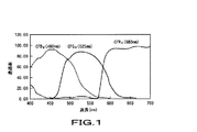
一般に、透過型のカラー液晶表示装置では、例えば、図1に示すような分光特性(スペクトル特性)の青色フィルタCFB0(460nm)、緑色フィルタCFG0(530nm)、赤色フィルタCFR0(685nm)からなる3原色フィルタを用いたカラーフィルタが、カラー液晶表示パネルの画素毎に備えられている。なお、カッコ内の数値は、各フィルタのピーク透過波長を示している。
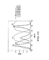
これに対し、カラー液晶表示装置のバックライト装置の光源として用いられる3波長域型のCCFLが発光する白色光は、図2に示すようなスペクトルを示し、様々な波長帯域で異なる強度の光を含んでいることになる。
したがって、このような3波長域発光型のCCFLを光源とするバックライト装置と、上述したようなカラーフィルタを備えるカラー液晶表示パネルとの組み合わせによって再現される色は、非常に色純度が悪いといった問題がある。
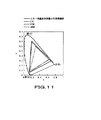
図3に、上述したような3波長域型のCCFLを光源としたバックライト装置を備えるカラー液晶表示装置の色再現範囲を示す。図3は、国際照明委員会(CIE:Commission Internationale de l'Eclairage)が定めたXYZ表色系のxy色度図である。
図3に示すようにCCFLを光源としたバックライト装置を備えたカラー液晶表示装置の色再現範囲は、カラーテレビジョンの放送方式として採用されているNTSC(National Television System Committee)方式の規格で定められている色再現範囲より狭い範囲となっており、現行のテレビジョン放送に十分対応できているとはいえない。
また、CCFLは、蛍光管内に水銀を封入するため、環境への悪影響が考えられるため、今後、バックライト装置の光源として、CCFLに代わる光源が求められている。そこで、CCFLに代わる光源として発光ダイオード(LED:Light Emitting Diode)が有望視されている。青色発光ダイオードの開発により、光の3である赤色光、緑色光、青色光をそれぞれ発光する発光ダイオードが揃ったことになる。したがって、この発光ダイオードをバックライト装置の光源とすることで、カラー液晶表示パネルを介した色光の色純度が高くなるため、色再現範囲をNTSC方式で規定される程度、さらには、それを超える程度まで広げることが期待されている。
しかし、発光ダイオードを光源とするバックライト装置を使用したカラー液晶表示装置の色再現範囲は、未だ、NTSC方式で規定された色再現範囲を満たすほど十分広くないといった問題がある。Instead of CRT (Cathode Ray Tube), which has been used for many years since the start of television broadcasting, it has become extremely thin, such as a liquid crystal display (LCD) and a plasma display panel (PDP). A television receiver has been developed and put into practical use. In particular, a color liquid crystal display device using a color liquid crystal display panel can be driven with low power consumption, and it is considered that the color liquid crystal display device will be accelerated and spread along with the price reduction of a large color liquid crystal display panel. Therefore, it is a display device that can be expected to develop further in the future.
The color liquid crystal display device is mainly a backlight system that displays a color image by illuminating a transmissive color liquid crystal display panel from the back side with a backlight device. As a light source of the backlight device, a CCFL (Cold Cathode Fluorescent Lamp) that emits white light using a fluorescent tube is often used.
In general, in a transmissive color liquid crystal display device, for example, a blue filter CFB 0 (460 nm), a green filter CFG 0 (530 nm), and a red filter CFR 0 (685 nm) having spectral characteristics (spectral characteristics) as shown in FIG. A color filter using the three primary color filters is provided for each pixel of the color liquid crystal display panel. The numerical value in parentheses indicates the peak transmission wavelength of each filter.
On the other hand, white light emitted from a three-wavelength type CCFL used as a light source of a backlight device of a color liquid crystal display device shows a spectrum as shown in FIG. 2, and emits light of different intensity in various wavelength bands. Will be included.
Therefore, the color reproduced by the combination of the backlight device using such a three-wavelength light emitting CCFL as the light source and the color liquid crystal display panel including the color filter as described above has very poor color purity. There's a problem.
FIG. 3 shows a color reproduction range of a color liquid crystal display device including a backlight device using the above-described three-wavelength type CCFL as a light source. FIG. 3 is an xy chromaticity diagram of the XYZ color system defined by the Commission Internationale de l'Eclairage (CIE).
As shown in FIG. 3, the color reproduction range of a color liquid crystal display device provided with a backlight device using CCFL as a light source is determined by the NTSC (National Television System Committee) standard adopted as a color television broadcasting method. It is a narrower range than the color reproduction range that is currently available, and it cannot be said that it is sufficiently compatible with current television broadcasting.
In addition, since CCFL encloses mercury in a fluorescent tube, there is an adverse effect on the environment. Therefore, in the future, a light source that replaces CCFL is required as a light source of a backlight device. Therefore, a light emitting diode (LED) is promising as a light source to replace CCFL. With the development of blue light-emitting diodes, light-emitting diodes that emit
However, there is still a problem that the color reproduction range of a color liquid crystal display device using a backlight device using a light emitting diode as a light source is not wide enough to satisfy the color reproduction range defined by the NTSC system.
本発明は、上述したような問題を解決するために提案されたものであり、バックライト方式の液晶表示装置の広色域化を可能にするバックライト装置及びこのバックライト装置を用いたカラー液晶表示装置を提供することにある。
本発明が適用されたバックライト装置は、赤色光、緑色光、青色光を波長選択透過する3原色フィルタからなるカラーフィルタを備えた透過型のカラー液晶表示パネルを背面側から白色光で照明するバックライト装置であって、このバックライト装置は、半値幅hwrが、15nm≦hwr≦30nmである赤色光を発光する赤色発光ダイオード、半値幅hwgが、25nm≦hwg≦50nmである緑色光を発光する緑色発光ダイオード及び半値幅hwbが、15nm≦hwb≦30nmである青色光を発光する青色発光ダイオードからなる光源と光源から発光された赤色光、緑色光及び青色光を混色して、白色光とする混色手段とを備える。
また、本発明が適用されたカラー液晶表示装置は、赤色光、緑色光、青色光を波長選択透過する3原色フィルタからなるカラーフィルタを備えた透過型のカラー液晶表示パネルと、カラー液晶表示パネルを背面側から白色光で照明するバックライト装置とを備えるカラー液晶表示装置であって、バックライト装置は、半値幅hwrが、15nm≦hwr≦30nmである赤色光を発光する赤色発光ダイオード、半値幅hwgが、25nm≦hwg≦50nmである緑色光を発光する緑色発光ダイオード及び半値幅hwbが、15nm≦hwb≦30nmである青色光を発光する青色発光ダイオードからなる光源と、光源から発光された赤色光、緑色光及び青色光を混色して、白色光とする混色手段とを有する。
本発明が適用されたバックライト装置は、白色光を生成し、この白色光で、赤色光、緑色光、青色光を波長選択透過する3原色フィルタからなるカラーフィルタを備えた透過型のカラー液晶表示パネルを背面側から照明することにより、光源となる赤色発光ダイオード、緑色発光ダイオード、青色発光ダイオードで発光される赤色光、緑色光、青色光の色純度を上げ、混色された白色光を光色域化することが可能となり、NTSC(National Television System Committee)比を100%以上とするような色再現範囲を達成することを可能とする。
また、本発明が適用された他のバックライト装置は、赤色光、緑色光、青色光を波長選択透過する3原色フィルタからなるカラーフィルタを備えた透過型カラー液晶表示パネルを背面側から白色光で照明するバックライト装置であって、このバックライト装置は、国際照明委員会(CIE:Commission Internationale de I'Eclariage)が定めたXYZ表色系のxy色度図中における色度点が0.65≦x≦0.75、0.27≦y≦0.33となる赤色光を発光する赤色発光ダイオード、xy色度図中の色度点が0.12≦x≦0.28、0.64≦y≦0.76である緑色光を発光する緑色発光ダイオード及びxy色度図中の色度点が0.14≦x≦0.17、0.01≦y≦0.06となる青色光を発光する青色発光ダイオードとからなる光源と、光源から発光された赤色光、緑色光及び青色光を混色して、白色光とする混色手段とを備える。
また、本発明が適用された他のカラー液晶表示装置は、赤色光、緑色光、青色光を波長選択透過する3原色フィルタからなるカラーフィルタを備えた透過型のカラー液晶表示パネルと、カラー液晶表示パネルを背面側から白色光で照明するバックライト装置とを備えるカラー液晶表示装置であって、バックライト装置は、国際照明委員会(CIE:Commission Internationale de I'Eclariage)が定めたXYZ表色系のxy色度図中における色度点が0.65≦x≦0.75、0.27≦y≦0.33となる赤色光を発光する赤色発光ダイオード、xy色度図中の色度点が0.12≦x≦0.28、0.64≦y≦0.76である緑色光を発光する緑色発光ダイオード及びxy色度図中の色度点が0.14≦x≦0.17、0.01≦y≦0.06となる青色光を発光する青色発光ダイオードとからなる光源と、光源から発光された赤色光、緑色光及び青色光を混色して、白色光とする混色手段とを備える。
このバックライト装置は、白色光を生成し、この白色光で、赤色光、緑色光、青色光を波長選択透過する3原色フィルタからなるカラーフィルタを備えた透過型のカラー液晶表示パネルを背面側から照明することにより、光源となる赤色発光ダイオード、緑色発光ダイオード、青色発光ダイオードで発光される赤色光、緑色光、青色光の色純度を上げ、混色された白色光を光色域化することが可能となり、NTSC(National Television System Committee)比を100%以上とするような色再現範囲を達成することを可能とする。このとき、発光ダイオードを光源とするカラー液晶表示装置の色域を最適化する際に、赤色発光ダイオード、緑色発光ダイオード、青色発光ダイオードから発光される各色光の色度点範囲を規定しているため、一般に発光ダイオードの波長のみを規定することで最適化を図る場合と較べて、より正確に最適な色域を再現することを可能とする。
本発明を適用したさらに他のカラー液晶表示装置は、カラーフィルタを備えた透過型のカラー液晶表示パネルと、このカラー液晶表示パネルを背面側から照明する液晶表示用バックライト光源とを備え、このバックライト光源は、赤色発光ダイオード、緑色発光ダイオード、青色発光ダイオードからなり、バックライト光源から発光された赤色光、緑色光、青色光を混色して白色光とする混色手段を備え、緑色発光ダイオードの発光スペクトルの半値幅が30nm〜40nmの範囲内であるものである。
このカラー液晶表示装置は、バックライト光源が、赤色発光ダイオード、緑色発光ダイオード、青色発光ダイオードから成ることにより、CCFL等の蛍光管を用いたバックライト光源を用いた場合と比較して、カラー液晶表示装置の色再現範囲を広げることができる。
また、緑色発光ダイオードの発光スペクトルの半値幅が30nm〜40nmの範囲内であることにより、半値幅が従来の構成よりも狭くなり、緑色と他の色(特に青色)との混色を抑制することができる。これにより、半値幅が大きい従来の構成と比較して、カラー液晶表示装置の色再現範囲を、緑色の領域において広げることができる。
本発明のさらに他の目的、本発明によって得られる具体的な利点は、以下において図面を参照して説明される実施に形態から一層明らかにされるであろう。The present invention has been proposed in order to solve the above-described problems, and a backlight device capable of widening the color gamut of a backlight type liquid crystal display device and a color liquid crystal using the backlight device. It is to provide a display device.
A backlight device to which the present invention is applied illuminates a transmissive color liquid crystal display panel having a color filter including three primary color filters that selectively transmit red light, green light, and blue light with white light from the back side. This backlight device is a red light emitting diode that emits red light with a half-value width hwr of 15 nm ≦ hwr ≦ 30 nm, and emits green light with a half-value width hwg of 25 nm ≦ hwg ≦ 50 nm. A green light emitting diode and a half-value width hwb of 15 nm ≦ hwb ≦ 30 nm are mixed with a light source composed of a blue light emitting diode that emits blue light and red light, green light, and blue light emitted from the light source, Color mixing means.
A color liquid crystal display device to which the present invention is applied includes a transmissive color liquid crystal display panel including a color filter including three primary color filters that selectively transmit red light, green light, and blue light, and a color liquid crystal display panel. And a backlight device that illuminates the backlight with white light from the back side, the backlight device including a red light-emitting diode that emits red light having a half-value width hwr of 15 nm ≦ hwr ≦ 30 nm, A light source composed of a green light emitting diode that emits green light whose value width hwg is 25 nm ≦ hwg ≦ 50 nm and a blue light emitting diode that emits blue light whose half width hwb is 15 nm ≦ hwb ≦ 30 nm, and light emitted from the light source Color mixing means for mixing white light with red light, green light and blue light.
The backlight device to which the present invention is applied is a transmissive color liquid crystal that includes a color filter including three primary color filters that generate white light and selectively transmit wavelengths of red light, green light, and blue light with the white light. Illuminating the display panel from the back side increases the color purity of red light, green light, and blue light emitted from the red, green, and blue light emitting diodes, and emits mixed white light. It becomes possible to achieve a color gamut and to achieve a color reproduction range in which the NTSC (National Television System Committee) ratio is 100% or more.
In another backlight device to which the present invention is applied, a transmissive color liquid crystal display panel including a color filter including three primary color filters that selectively transmit red light, green light, and blue light is white light from the back side. This backlight device has a chromaticity point in the xy chromaticity diagram of the XYZ color system defined by the Commission Internationale de I'Eclariage (CIE). Red light emitting diode that emits red light satisfying 65 ≦ x ≦ 0.75 and 0.27 ≦ y ≦ 0.33, and the chromaticity point in the xy chromaticity diagram is 0.12 ≦ x ≦ 0.28, 0. Green light-emitting diode emitting green light with 64 ≦ y ≦ 0.76 and blue with chromaticity points in the xy chromaticity diagram of 0.14 ≦ x ≦ 0.17 and 0.01 ≦ y ≦ 0.06 A light source comprising a blue light emitting diode emitting light, and light A color mixing unit that mixes red light, green light, and blue light emitted from the light source to form white light.
Another color liquid crystal display device to which the present invention is applied includes a transmissive color liquid crystal display panel including a color filter including three primary color filters that selectively transmit red light, green light, and blue light, and a color liquid crystal. A color liquid crystal display device comprising a backlight device that illuminates the display panel with white light from the back side, and the backlight device is an XYZ color specification defined by the Commission Internationale de I'Eclariage (CIE) Red light-emitting diode that emits red light with chromaticity points 0.65 ≦ x ≦ 0.75 and 0.27 ≦ y ≦ 0.33 in the xy chromaticity diagram of the system, chromaticity in the xy chromaticity diagram A green light-emitting diode that emits green light whose points are 0.12 ≦ x ≦ 0.28 and 0.64 ≦ y ≦ 0.76, and a chromaticity point in the xy chromaticity diagram is 0.14 ≦ x ≦ 0. 17, blue that satisfies 0.01 ≦ y ≦ 0.06 A light source including a blue light emitting diode that emits colored light, and a color mixing unit that mixes red light, green light, and blue light emitted from the light source to generate white light.
This backlight device generates white light, and a transmissive color liquid crystal display panel having a color filter composed of three primary color filters that selectively transmits red light, green light, and blue light with the white light. By illuminating from the light source, the color purity of the red, green, and blue light emitted by the red, green, and blue light emitting diodes is increased, and the mixed white light is converted into the light color gamut. Therefore, it is possible to achieve a color reproduction range in which the NTSC (National Television System Committee) ratio is 100% or more. At this time, when optimizing the color gamut of the color liquid crystal display device using the light emitting diode as a light source, the chromaticity point range of each color light emitted from the red light emitting diode, the green light emitting diode, and the blue light emitting diode is defined. Therefore, in general, it is possible to reproduce the optimum color gamut more accurately than in the case of optimization by defining only the wavelength of the light emitting diode.
Still another color liquid crystal display device to which the present invention is applied includes a transmissive color liquid crystal display panel including a color filter, and a backlight light source for liquid crystal display that illuminates the color liquid crystal display panel from the back side. The backlight light source includes a red light emitting diode, a green light emitting diode, and a blue light emitting diode, and includes a color mixing unit that mixes red light, green light, and blue light emitted from the backlight light source to form white light, and is a green light emitting diode. The half-value width of the emission spectrum is in the range of 30 nm to 40 nm.
In this color liquid crystal display device, since the backlight light source is composed of a red light emitting diode, a green light emitting diode, and a blue light emitting diode, the color liquid crystal is compared with the case where a backlight light source using a fluorescent tube such as CCFL is used. The color reproduction range of the display device can be expanded.
In addition, since the half-value width of the emission spectrum of the green light-emitting diode is in the range of 30 nm to 40 nm, the half-value width becomes narrower than the conventional configuration, and the color mixture between green and other colors (especially blue) is suppressed. Can do. As a result, the color reproduction range of the color liquid crystal display device can be expanded in the green region as compared with the conventional configuration having a large half width.
Other objects of the present invention and specific advantages obtained by the present invention will become more apparent from the embodiments described below with reference to the drawings.
以下、本発明の実施の形態を図面を参照して詳細に説明をする。本発明は、以下の例に限定されるものではなく、本発明の要旨を逸脱しない範囲で、任意に変更可能であることはいうまでもない。
本発明は、例えば、図4に示すような構成のバックライト方式のカラー液晶表示装置100に適用される。
この透過型のカラー液晶表示装置100は、図4に示すように、透過型のカラー液晶表示パネル10と、このカラー液晶表示パネル10の背面側に設けられたバックライトユニット40とを備える。このカラー液晶表示装置100は、図示しないが、地上波や衛星波を受信するアナログチューナ、デジタルチューナといった受信部、この受信部で受信した映像信号、音声信号をそれぞれ処理する映像信号処理部、音声信号処理部、音声信号処理部で処理された音声信号を出力するスピーカ等の音声信号出力部などを備えていてもよい。
透過型のカラー液晶表示パネル10は、ガラス等で構成された2枚の透明な基板(TFT基板11、対向電極基板12)を互いに対向配置させ、その間隙に、例えば、ツイステッドネマチック(TN)液晶を封入した液晶層13を設けた構成となっている。TFT基板11には、マトリクス状に配置された信号線14と、走査線15と、この信号線14、走査線15の交点に配置されたスイッチング素子としての薄膜トランジスタ16と、画素電極17とが形成されている。薄膜トランジスタ16は、走査線15により、順次選択されるとともに、信号線14から供給される映像信号を、対応する画素電極17に書き込む。一方、対向電極基板12の内表面には、対向電極18及びカラーフィルタ19が形成されている。
続いて、カラーフィルタ19について説明をする。カラーフィルタ19は、各画素に対応した複数のセグメントに分割されている。例えば、図5に示すように、3原色である赤色フィルタCFR、緑色フィルタCFG、青色フィルタCFBの3つのセグメントに分割されている。カラーフィルタの配列パターンは、図5に示すようなストライプ配列の他に、図示しないが、デルタ配列、正方配列などがある。
このカラー液晶表示装置100では、このような構成の透過型のカラー液晶表示パネル10を2枚の偏光板31,32で挟み、バックライトユニット40により背面側から白色光を照射した状態で、アクティブマトリクス方式で駆動することによって、所望のフルカラー映像を表示させることができる。
バックライトユニット40は、カラー液晶表示パネル10を背面側から照明する。このバックライトユニット40は、図4に示すように、光源を備え、この光源から出射された光を混色した白色光を光出射面20aから面発光するバックライト装置20と、このバックライト装置20の光出射面20a上に順に積層させる拡散シート41、プリズムシート42、偏光変換シート43といった光学機能シート群とから構成されている。
光学機能シート群は、例えば、入射光を直交する偏光成分に分解する機能、光波の位相差を補償して広角視野角化や着色防止を図る機能、入射光を拡散させる機能、輝度向上を図る機能などを備えたシートで構成されており、バックライト装置20から面発光された光をカラー液晶表示パネル10の照明に最適な光学特性を有する照明光に変換するために設けられている。したがって、光学機能シート群の構成は、上述した拡散シート41、プリズムシート42、偏光変換シート43に限定されるものではなく、様々な光学機能シートを用いることができる。
図6にバックライト装置20の概略構成図を示す。バックライト装置20は、図6に示すように、赤色光を発光する赤色発光ダイオード21R、緑色光を発光する緑色発光ダイオード21G、青色光を発光する青色発光ダイオード21Bを光源として用いている。なお、以下の説明において、赤色発光ダイオード21R、緑色発光ダイオード21G、青色発光ダイオード21Bを総称する場合は、単に発光ダイオード21という。
図6に示すように各発光ダイオード21は、基板22上に、所望の順番で一列に配列され、発光ダイオードユニット21n(nは、自然数。)を形成する。基板22上に各発光ダイオードを配列する順番は、例えば、図6に示すように、緑色発光ダイオード21Gを等間隔で配置させ、等間隔で配置させた、隣り合う緑色発光ダイオード21Gの間に、赤色発光ダイオード21R、青色発光ダイオード21Bを交互に配置させるような順番である。
発光ダイオードユニット21nは、バックライトユニット40が照明するカラー液晶表示パネル10のサイズに応じて、バックライト装置20の筐体であるバックライトハウス23内に、複数列、配置されることになる。
バックライトハウス23内への発光ダイオードユニット21nの配置の仕方は、図6に示すように、発光ダイオードユニット21nの長手方向が、水平方向となるように配置してもよいし、図示しないが、発光ダイオードユニット21nの長手方向が垂直方向となるように配置してもよいし、両者を組み合わせてもよい。
なお、発光ダイオードユニット21nの長手方向を、水平方向又は垂直方向とするように配置する手法は、従来までのバックライト装置の光源として利用していたCCFLの配置の仕方と同じになるため、蓄積された設計ノウハウを利用することができ、コストの削減や、製造までに要する時間を短縮することができる。
バックライトハウス23内に組み込まれた赤色発光ダイオード21R、緑色発光ダイオード21G、青色発光ダイオード21Bから発光された光は、当該バックライトハウス23内で混色されて白色光とされる。このとき、各発光ダイオード21から出射した赤色光、緑色光、青色光が、バックライトハウス23内にて一様に混色されるように、各発光ダイオード21には、レンズやプリズム、反射鏡などを配置させて、広指向性の出射光が得られるようにする。
また、バックライトハウス23内には、図示しないが、光源である発光ダイオード21から出射された各色光を色ムラの少ない白色光に混色する混色機能を備えたダイバータプレートや、このダイバータプレートから出射した白色光を面状発光させるために面方向に内部拡散させる拡散板などが設けられている。
バックライト装置20から混色されて出射された白色光は、上述した光学機能シート群を介して、カラー液晶表示パネル10に背面側から照明される。
このカラー液晶表示装置100は、例えば、図7に示すような駆動回路200により駆動される。
この駆動回路200は、カラー液晶表示パネル10や、バックライト装置20の駆動電源を供給する電源部110、カラー液晶表示パネル10を駆動するXドライバ回路120及びYドライバ回路130、外部から供給される映像信号や、当該カラー液晶表示装置100が備える図示しない受信部で受信され、映像信号処理部で処理された映像信号が、入力端子140を介して供給されるRGBプロセス処理部150、このRGBプロセス処理部150に接続された画像メモリ160及び制御部170、バックライトユニット40のバックライト装置20を駆動制御するバックライト駆動制御部180などを備えている。
この駆動回路200において、入力端子140を介して入力された映像信号は、RGBプロセス処理部150により、クロマ処理などの信号処理がなされ、さらに、コンポジット信号からカラー液晶表示パネル10の駆動に適したRGBセパレート信号に変換されて、制御部170に供給されるとともに、画像メモリ160を介してXドライバ回路120に供給される。
また、制御部170は、RGBセパレート信号に応じた所定のタイミングで、Xドライバ回路120及びYドライバ回路130を制御して、画像メモリ160を介してXドライバ回路120に供給されるRGBセパレート信号で、カラー液晶表示パネル10を駆動することにより、RGBセパレート信号に応じた映像を表示する。
バックライト駆動制御部180は、電源部110から供給される電圧から、パルス幅変調(PWM)信号を生成し、バックライト装置20の光源である各発光ダイオード21を駆動する。一般に発光ダイオードの色温度は、動作電流に依存するという特性がある。したがって、所望の輝度を得ながら、忠実に色再現させる(色温度を一定とする)には、パルス幅変調信号を使って発光ダイオード21を駆動し、色の変化を抑える必要がある。
ユーザインタフェース300は、上述した図示しない受信部で受信するチャンネルを選択したり、同じく図示しない音声出力部で出力させる音声出力量を調整したり、カラー液晶表示パネル10を照明するバックライト装置20からの白色光の輝度調節、ホワイトバランス調節などを実行するためのインタフェースである。
例えば、ユーザインタフェース300から、ユーザが輝度調節をした場合には、駆動回路200の制御部170を介してバックライト駆動制御部180に輝度制御信号が伝わる。バックライト駆動制御部180は、この輝度制御信号に応じて、パルス幅変調信号のデューティ比を、赤色発光ダイオード21R、緑色発光ダイオード21G、青色発光ダイオード21B毎に変えて、赤色発光ダイオード21R、緑色発光ダイオード21G、青色発光ダイオード21Bを駆動制御することになる。
このような構成のカラー液晶表示装置100は、カラー液晶表示パネル10に設けられる赤色フィルタCFR、緑色フィルタCFG、青色フィルタCFBの特性と、バックライト装置20に設けられる発光ダイオード21R,21G,21Bの特性とのマッチングを図り最適化することで、カラー液晶表示パネル10に表示される画像の色再現範囲を拡大させる。
なお、図示しないが、カラー液晶表示装置100に、地上波や衛星波を受信するアナログチューナ、デジタルチューナといった受信部、この受信部で受信した映像信号、音声信号をそれぞれ処理する映像信号処理部、音声信号処理部、音声信号処理部で処理した音声信号を出力するスピーカといった音声信号出力部等を備えていてもよい。
このような構成のカラー液晶表示装置100では、カラー液晶表示パネル10が備えるカラーフィルタ19が、例えば、それぞれ図8に示すような分光特性となる赤色フィルタCFR(680nm)、緑色フィルタCFG(525nm)、青色フィルタCFB(460nm)によって構成されている。なお、カッコ内の数値は、各フィルタのピーク透過波長を示している。
バックライトユニット40によって照明されたカラー液晶表示パネル10を介した表示光の色純度を上げ、色域を広げるためには、カラーフィルタ19を構成する色フィルタのうち透過波長帯域が隣接する色フィルタ同士をなるべく遠ざけるようにする必要がある。
例えば、赤色フィルタCFRの透過波長帯域を長波長側にシフトさせ、緑色発光ダイオード21Gで発光される緑色光が、なるべく赤色フィルタCFRを透過しないようにする。また、青色フィルタCFBの透過波長帯域を短波長側にシフトさせ、緑色発光ダイオード21Bで発光される緑色光がなるべく青色フィルタCFBを透過しないようにする。
また、赤色フィルタCFRの透過波長帯域の長波長側へのシフト、青色フィルタCFBの短波長側へのシフトに伴い、赤色発光ダイオード21Rで発光される赤色光のピーク波長も長波長側へシフトさせ、青色発光ダイオード21Bで発光される青色光のピーク波長も短波長側へシフトさせると、それぞれ緑色フィルタCFGの透過波長帯域を透過する割合の減少により混色が抑制されるため色純度が上がり、色域を広げることができる。
このように、色純度を上げ、色域を広げるためには、赤色フィルタCFR、緑色フィルタCFG、青色フィルタCFBの透過波長帯域並びに赤色発光ダイオード21R、緑色発光ダイオード21G、青色発光ダイオード21Bのピーク波長が重要となってくる。
また、人の目の光に対する感度(視感度)は、波長によって異なっており、図9に示すように、555nmでピークをとり、長波長側、短波長側になるにつれ低くなっていく。図9は、視感度がピークとなる555nmを1とした比視感度曲線である。
したがって、赤色発光ダイオード21Rで発光される赤色のピーク波長、青色発光ダイオード21Bで発光される青色光のピーク波長をそれぞれ、長波長側、短波長側にシフトしすぎると視感度が下がるため、視感度を上げるためには非常に高いパワーが必要になってしまう。
そこで、赤色発光ダイオード21Rで発光される赤色光のピーク波長、青色発光ダイオード21Bで発光される青色光のピーク波長を、パワー効率を下げない程度に、それぞれ長波長側、短波長側にシフトさせることで、色純度を上げ、色域を広げることが可能となる。
{半値幅について}
光源である発光ダイオード21に関しては、上述したピーク波長のみならず、そのスペクトル分布も色純度を上げ、色域を広げる際には非常に重要なファクタとなる。発光ダイオード21のスペクトル分布は、基本的にはガウス分布に従うが、製造プロセスやその他の要因により多様なスペクトル分布形状を示す。したがって、発光ダイオード21のピーク波長を特定しただけだと、スペクトル分布までは分かいため、スペクトル分布の違いによる色度点への影響が無視されてしまい、正確な色再現範囲を規定することができないことになる。
そこで、PW(Pulse Width)50又はFWHM(Full Width at Half Maximum)と呼ばれるスペクトル分布の半値幅を用いると、スペクトル分布形状をおおよそ特定することができる。例えば、発光ダイオード21から発光される各色光の半値幅を狭くするほど、隣接する色フィルタの透過波長帯域に重ならないようなスペクトル分布となるためカラーフィルタ19を透過した光の色純度が上がり、色域が広がることになる。しかし、半値幅を狭くすると輝度が減少するため、所望の輝度を確保するには、ある程度の半値幅が必要となる。
特に、図9に示した比視感度曲線からも分かるように、緑色光の視感度は非常に高いため、緑色発光ダイオード21Gで発光する緑色光の半値幅は、他の色光の半値幅と較べて広く確保する必要がある。したがって、緑色光の半値幅は、通常、赤色光、青色光の半値幅の2倍程度となっている。
このように、各色光の半値幅は、ピーク波長だけでは限定することができないスペクトル分布形状をおおよそ特定できるため、色純度を上げ、色域を広げるのに最適な色度点の範囲を規定する場合には非常に重要な値となる。そこで、以下に示す測定1から4における測定により、色純度を上げ、色域を広げるように、赤色発光ダイオード21R、緑色発光ダイオード21G、青色発光ダイオード21Bで発光される赤色光、緑色光、青色光の半値幅の最適な範囲を求める。
{測定1}
まず、半値幅の最適な範囲を求めるために、図8に示したカラーフィルタ19に対応した最適なピーク波長を有する赤色発光ダイオード21R(ピーク波長λpr:640nm)、緑色発光ダイオード21G(ピーク波長λpg:525nm)、青色発光ダイオード21B(ピーク波長λpb:450nm)を用いて色度点を測定し、NTSC(National Television System Committee)比を求める。
このとき、赤色光の半値幅hwrを22nm、緑色光の半値幅hwgを37nm、青色光の半値幅を25nmとすると、カラーフィルタ19の分光特性と、発光ダイオード21の分光特性とは、図10に示すようになる。このような特性の発光ダイオード21を発光させた際の色度点を測定し、国際照明委員会(CIE)が定めたXYZ表色系のxy色度図中にプロットすると、カラー液晶表示装置100の色再現範囲は、図11に示すようになる。また、カラー液晶表示パネル10を透過後のNTSC比を求めると、105.3%となりNTSC比100%以上となることが分かる。
なお、図11には、参考としてNTSC方式の色再現範囲の他に、コンピュータディスプレイ用の標準色空間としてIEC(International Electro-technical Commission)が規定したsRGB規格の色再現範囲も示している。
以後の測定では、この図10に示したスペクトル分布の赤色光、緑色光、青色光をそれぞれ発光する赤色発光ダイオード21R、緑色発光ダイオード21G、青色発光ダイオード21Bを基準の発光ダイオード21とする。この基準となる各発光ダイオード21のピーク波長λpと、半値幅hwとの関係を、以下の表1に示す。
表1

{測定2}
続いて、緑色発光ダイオード21Gと、青色発光ダイオード21Bとのピーク波長間隔を狭め、混色の影響が高くなるようにした場合において、緑色光の半値幅が異なる緑色発光ダイオード21Gを3種類用意し、緑色光の半値幅の最適範囲を求める。
図10からも分かるように、NTSC比100%以上を達成するような緑色光のピーク波長と、青色光のピーク波長との間隔(ピーク波長間隔)は、赤色光のピーク波長と、緑色光のピーク波長間隔と比較して狭くなっている。
これは、例えば、輝度を確保するために緑色光の半値幅を広くした場合には、緑色光が、青色フィルタCFBの透過波長帯域を透過する割合が増加するため、混色が起こり色純度の低下を招き、色域が狭くなってしまうことを示唆している。したがって、緑色光のピーク波長と、青色光のピーク波長とを近づけた場合でも、NTSC比100%以上となる緑色光の半値幅を求めれば、緑色光の半値幅の上限が分かることになる。
具体的には、緑色発光ダイオード21G、青色発光ダイオード21Bのピーク波長を、図10に示した基準のピーク波長からそれぞれ5nmだけそれぞれ短波長側、長波長側にシフトさせて、緑色光のピーク波長λpgを520nm、青色光のピーク波長λprを455nmとして、緑色光と、青色光のピーク波長間隔を狭める。赤色発光ダイオード21Rは、発光する赤色光のピーク波長λprが測定1のときと同じ640nmとなるようなものを選択する。半値幅は、測定1のときと同様に、赤色光の半値幅hwrを22nm、青色光の半値幅を25nmとして固定した。このとき、緑色発光ダイオード21Gとしては、緑色光の半値幅hwgが、37nm、43nm、74nmとなるものを3種類用意する。以上、発光ダイオード21の条件をまとめると、以下の表2に示すようになり、測定2においては、このようなピーク波長λp、半値幅hwとなる赤色発光ダイオード21R、緑色発光ダイオード21G、青色発光ダイオード21Bを用いた測定を行う。
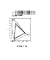
このときのカラーフィルタ19の分光特性と、発光ダイオード21の分光特性とは、図12に示すようになる。また、緑色光の半値幅を変えて発光ダイオード21を発光させた際の色度点を測定し、国際照明委員会(CIE)が定めたXYZ表色系のxy色度図中にプロットすると、カラー液晶表示装置100の色再現範囲は、それぞれ図13に示すようになる。なお、図13には、参考として図11に示した基準となる赤色発光ダイオード21R、緑色発光ダイオード21G、青色発光ダイオード21Bによる色再現範囲も示してある。図13に示すように、緑色光の半値幅が広くなるほど、緑色光と、青色光との領域で混色が発生するため、色域が狭くなっていることが分かる。
表2
図14に、カラー液晶表示パネル10を透過した光に対して求められたNTSC比の、緑色光の半値幅依存性を示す。図14からも分かるように、緑色光の半値幅が広がるにつれて、NTSC比が低下し、色域が狭くなっている。具体的には、NTSC比100%を維持するには、緑色光の半値幅hwgを50nm以下にする必要がある。つまり、緑色光の半値幅hwgが50nmよりも広くなるとNTSC比100%を達成することができないことになる。
このように、測定2では、緑色光のピーク波長λpgと、青色光のピーク波長λpbとの間隔を狭めたワーストケースにて、緑色光の半値幅hwgを可変させた。これにより、色純度を上げ、NTSC比が100%以上となるような広色域を達成するためには、緑色光の半値幅hwgを50nm以下に規定する必要があることが分かる。
{測定3}
続く測定3では、青色光のピーク波長と、緑色光のピーク波長とのピーク波長間隔による影響を検証するために、ピーク波長λpbが450nm、455nm、460nmである3種類の青色発光ダイオード21Bを新たに用意した。この青色発光ダイオード21Bそれぞれに対して、測定2でも用いた半値幅hwgが37nm、43nm、74nmの緑色発光ダイオード21Gを組み合わせて、バックライト装置20の光源とし、NTSC比を求めることで、緑色光と青色光とのピーク波長間隔の違いに応じた最適な緑色光の半値幅の上限を求めることができる。赤色発光ダイオード21Rとしては、ピーク波長λprが640nm、半値幅hwrが22nmである赤色光を発光するものが選択される。また、青色発光ダイオード21Rが発光する青色光の半値幅hwrは、25nmで固定とする。
以上、発光ダイオード21の条件をまとめると、以下に示す表3(λpb=450nm)、表4(λpb=460nm)に示すようになり、測定3においては、このようなピーク波長λp、半値幅hwとなる赤色発光ダイオード21R、緑色発光ダイオード21G、青色発光ダイオード21Bを用いた測定を行う。なお、λpb=455nmにおいては、上述の表2にて記載した測定2と同じ条件であるため記載を省略する。
表3
表4
図15に、青色光のピーク波長(λpb:450nm、455nm、460nm)毎に、緑色光の半値幅を変化(hwg:37nm、43nm、74nm)させた際のカラー液晶表示パネル10を透過後のNTSC比の変化の様子を示す。図16に示すように、青色発光ダイオード21Bから発光される青色光のピーク波長λpbが455nm以下であれば、緑色発光ダイオード21Gから発光される緑色光の半値幅hwgが50nm以下のときにNTSC比100%以上を達成することができる。しかし、青色光のピーク波長λpbが460nmの場合には、緑色光の半値幅hwgを43nm以下にしないとNTSC比100%を達成することができないことが分かる。
{測定4}
各色光を発光する発光ダイオード21の半値幅は、上述したように、赤色光、青色光よりも必ず広くとる必要がある緑色光の半値幅hwgを規定すれば、NTSC比100%以上を達成できる程度に色純度を上げ、広色域とすることができる。しかしながら、上述したように、緑色光のピーク波長と、青色光のピーク波長とは、ピーク波長間隔が狭いため、青色光の半値幅によっては、緑色フィルタCFGの透過波長帯域を透過する割合が増え、混色が起こり色純度の低下を生じてしまう可能性もある。そこで、この測定4では、青色光の半値幅による影響を検証する。
具体的には、測定1乃至3においては、25nmで固定とされていた青色光の半値幅hwrを5nm広げた30nmとし、ピーク波長λpbを455nmとする青色発光ダイオード21Bを用意し、さらに測定2でも用いた半値幅hwgが37nm、43nm、74nmの緑色発光ダイオード21Gを用いて、それぞれにおけるカラー液晶表示装置100の色再現範囲を測定し、NTSC比を求める。赤色発光ダイオード21Rは、発光する赤色光のピーク波長λprが640nm、半値幅hwrが22nmとなるようなものを選択する。
以上、発光ダイオード21の条件をまとめると、以下の表5に示すようになり、測定4においては、このようなピーク波長λp、半値幅hwとなる赤色発光ダイオード21R、緑色発光ダイオード21G、青色発光ダイオード21Bを用いた測定を行う。
表5
このときのカラーフィルタ19の分光特性と、発光ダイオード21の分光特性とは、図16に示すようになる。また、xy色度図中に測定した色度点をプロットするとカラー液晶表示装置100の色再現範囲は、図17に示すようになる。
さらに、図18に、カラー液晶表示パネル10を透過した光に対して求められたNTSC比の、緑色光の半値幅依存性を示す。図18には、表2で示した、青色光の半値幅hwbを25nmにした場合におけるNTSC比の緑色光の半値幅依存性も示す。図18からも分かるように、青色光の半値幅hwbが30nmというように広がった場合でも、緑色光の半値幅hwgが45nm以下であればNTSC比100%以上の色域を達成することができる。これにより、青色光を発光する青色発光ダイオード21Bは、青色光の半値幅hwbが30nmまで、NTSC比100%以上の色域を達成する許容範囲となることが分かる。
なお、赤色発光ダイオード21Rから発光される赤色光の半値幅は、赤色光−緑色光間のピーク波長間隔が、緑色光−青色光間のピーク波長間隔よりも広いため、少なくとも30nmまでは許容範囲とすることができる。また、各色光の半値幅の最小値は、上述したように狭いほど混色に対しては有効に機能するが、製造上実現できる範囲として、最大値の半分に規定することにする。
このようにして、赤色発光ダイオード21R、緑色発光ダイオード21G、青色発光ダイオード21Bでそれぞれ発光される赤色光、緑色光、青色光の各半値幅は、15nm≦hwr≦30nm、25nm≦hwg≦50nm、15nm≦hwb≦30nmと規定することができる。
これにより、単純にピーク波長範囲のみだけではなく、各色光のスペクトル分布の違いも考慮されるため、カラー液晶表示装置100の色再現範囲を、極めて正確にNTSC比100%以上を達成できるような色再現範囲とすることができる。
また、カラーフィルタ19を備えるカラー液晶表示パネル10をバックライト装置20で照明する場合、光源となる赤色発光ダイオード21R、緑色発光ダイオード21G、青色発光ダイオード21Bの波長帯域及びカラーフィルタ19が備える色フィルタの透過波長帯域を適切に選択しないと、従来技術で説明したCCFLのように色純度が悪化し、色域を狭めることになってしまう。
以下、バックライト装置20の光源である赤色発光ダイオード21R、緑色発光ダイオード21G、青色発光ダイオード21Bのピーク波長をそれぞれシフトさせ(波長帯域を変え)、上述したパワー効率の低減を避けながら、色純度が高く、色域が広い白色光となるような最適なピーク波長帯域を決定する例を説明する。
具体的には、2つの発光ダイオードのピーク波長を固定しておき、残る一つの発光ダイオードをピーク波長の異なるものを幾つか用意して、それらを取り替えながらそのときのNTSC(National Television System Committee)比を取り、NTSC比が100%を越えた場合の波長帯域を、赤色発光ダイオード21R、緑色発光ダイオード21G、青色発光ダイオード21Bで発光させる最適なピーク波長帯域とする。このとき、赤色光のピーク波長、青色光のピーク波長は、上述した視感度によって決まるパワー効率を低下させない範囲内とする。
{赤色発光ダイオード21R}
まず、青色発光ダイオード21B、緑色発光ダイオード21Gのピーク波長を固定し、異なるピーク波長の赤色発光ダイオード21Rを用いて、NTSC比を測定し、赤色発光ダイオード21Rの最適なピーク波長帯域を求める。
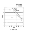
図19Aは、図8でも示したカラーフィルタ19の分光特性と、赤色発光ダイオード21R、緑色発光ダイオード21G、青色発光ダイオード21Bで発光された赤色光、緑色光、青色光の波長スペクトルを示した図である。赤色発光ダイオード21Rは、ピーク波長が(600+10N)nmの赤色発光ダイオード21RN(N=0,1,2,…7,8,9)を10個用意した。緑色発光ダイオード21Gとしては、ピーク波長が525nmのものを用意し、青色発光ダイオード21Bとしては、ピーク波長が450nmのものを用意した。
図19Bは、ピーク波長が(600+10N)nmの赤色発光ダイオード21RNを用いた際のNTSC比を測定した結果である。図19Bに示すように、赤色発光ダイオード21RNのピーク波長λprが625nm≦λpr≦685nm以下のときNTSC比が100%以上となる。
したがって、赤色発光ダイオード21Rの最適なピーク波長帯域は、625nm≦λpr≦685nmということになる。
なお、赤色発光ダイオード21R、緑色発光ダイオード21G、青色発光ダイオード21Bから出射される赤色光、緑色光、青色光、それぞれのスペクトルの半値幅hwr、hwg、hwbは、それぞれ、hwr=22nm,hwg=40nm,hwb=25nmとした。
{緑色発光ダイオード21G}
次に、赤色発光ダイオード21R、青色発光ダイオード21Bのピーク波長を固定して、異なるピーク波長の緑色発光ダイオード21Gを用いて、NTSC比を測定し、緑色発光ダイオード21Gの最適なピーク波長帯域を求める。
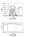
図20Aは、前述した図8でも示したカラーフィルタ19の分光特性と、赤色発ダイオード21R、緑色発光ダイオード21G、青色発光ダイオード21Bで発光された赤色光、緑色光、青色光の波長スペクトルを示した図である。緑色発光ダイオード21Gは、ピーク波が(495+10N)nmの緑色発光ダイオード21GN(N=0,1,2,3,4,5,6)を7個用意した。赤色発光ダイオード21Rとしては、ピーク波長が640nmのものを用意し、青色発光ダイオード21Bとしては、ピーク波長が450nmのものを用意した。
図20Bは、ピーク波長が(495+10N)nmの緑色発光ダイオード21GNを用いた際のNTSC比を測定した結果である。図8Bに示すように緑色発光ダイオード21GNのピーク波長λpgが505nm≦λpg≦535nm以下のとき、NTSC比が100%以上となる。
したがって、緑色発光ダイオード21Gの最適なピーク波長帯域は、505nm≦λpg≦535nmということになる。
なお、赤色発光ダイオード21R、緑色発光ダイオード21G、青色発光ダイオード21Bから出射される赤色光、緑色光、青色光、それぞれのスペクトルの半値幅hwr、hwg、hwbは、それぞれ、hwr=22nm,hwg=40nm,hwb=25nmとした。
{青色発光ダイオード21B}
続いて、次に、赤色発光ダイオード21R、緑色発光ダイオード21Gのピーク波長を固定して、異なるピーク波長の青色発光ダイオード21Bを用いて、NTSC比を測定し、青色発光ダイオード21Bの最適なピーク波長帯域を求める。
図21Aは、図8でも示したカラーフィルタ19の分光特性と、赤色発ダイオード21R、緑色発光ダイオード21G、青色発光ダイオード21Bで発光された赤色光、緑色光、青色光の波長スペクトルを示した図である。青色発光ダイオード21Bは、ピーク波が(410+10N)nmの青色発光ダイオード21BN(N=0,1,2,…5,6,7)を8個用意した。赤色発光ダイオード21Gとしては、ピーク波長が640nmのものを用意し、緑色発光ダイオード21Bとしては、ピーク波長が525nmのものを用意した。
図21Bは、ピーク波長が(410+10N)nmの青色発光ダイオード21BNを用いた際のNTSC比を測定した結果である。図21Bに示すように青色発光ダイオード21BNのピーク波長λpbが420nm≦λpb≦465nmのとき、NTSC比が100%以上となる。
したがって、青色発光ダイオード21Bの最適なピーク波長帯域は、420nm≦λpr≦465nmということになる。
なお、赤色発光ダイオード21R、緑色発光ダイオード21G、青色発光ダイオード21Bから出射される赤色光、緑色光、青色光、それぞれのスペクトルの半値幅hwr、hwg、hwbは、それぞれ、hwr=22nm,hwg=40nm,hwb=25nmとした。
このように、赤色発光ダイオード21R、緑色発光ダイオード21G、青色発光ダイオード21Bから発光される赤色光、緑色光、青色光のピーク波長をそれぞれ上述した範囲内とすることで、バックライト装置20から出射される白色光の色純度を高め、従来の技術として示したCCFLを光源として用いた場合に較べて色域を広げることができる。したがって、カラー液晶表示装置100の色再現範囲を非常に広くすることができる。
{色度点について}
このように、NTSC比が100%以上となる発光ダイオード21の最適なピーク波長帯域を求めることはできるが、このピーク波長のみならず、そのスペクトル分布も色純度を上げ、色域を広げる際には非常に重要なファクタとなる。発光ダイオード21のスペクトル分布は、基本的にはガウス分布に従うが、製造プロセスやその他の様々な要因により多様なスペクトル分布形状示す。したがって、発光ダイオード21のピーク波長を特定しただけだと、スペクトル分布までは分かいため、スペクトル分布の違いによる色度点への影響が無視されてしまい、正確な色再現範囲を規定することができないことになる。
そこで、従来までは、発光ダイオード21のピーク波長を特定することで色域の最適化を行っていたが、本発明においては、色再現範囲がNTSC比100%以上を達成する際の各発光ダイオード21の色度点を測定し、測定された色度点の範囲で規定さる発光ダイオード21を用いることで色域の最適化を図ることにする。
そこで、上述したように、NTSC比を100%以上とするピーク波長範囲にある赤色発光ダイオード21R、緑色発光ダイオード21G、青色発光ダイオード21Bの色度点を測定することにする。具体的には、カラー液晶表示パネル10を取り除いたバックライト装置20を用い、各色光毎に発光ダイオード21を発光させた際の色度を測色計にて測定する。
このように、NTSC比を100%以上とするピーク波長範囲にある赤色発光ダイオード21R、緑色発光ダイオード21G、青色発光ダイオード21Bの色度点を国際照明委員会(CIE)が定めたXYZ表色系のxy色度図中にプロットした結果を、図22A及び図22B、図23A及び図23B、図24A及び図24Bに示す。色度点は、上述したように求めたピーク波長範囲の中から各色3種類ずつ選択してバックライト装置20に配列させ、赤色発光ダイオード21R、緑色発光ダイオード21G、青色発光ダイオード21Bを、それぞれ各色光毎に発光させた際の色光を、カラー液晶表示パネル10を介さずに測定をした。
{赤色発光ダイオード21Rの色度点}
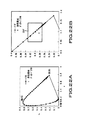
図22Aは、ピーク波長がそれぞれ630nm,640nm,670nmの赤色発光ダイオード21R、3つの色度点をxy色度図中にプロットした図であり、図22Bは、プロットされた色度点を拡大して示した図である。したがって、上述して求めた赤色発光ダイオード21Rの最適なピーク波長帯域625nm≦λpr≦685nmに対して、xy色度図中にプロットした赤色発光ダイオード21Rのピーク波長が630nm,640nm,670nmであることを考慮すると、赤色発光ダイオード21Rの最適な色度点領域は、図22Bに枠で囲んだ領域RFとなり、0.65≦x≦0.75、0.27≦y≦0.33と規定することができる。
{緑色発光ダイオード21Gの色度点}
図23Aは、ピーク波長がそれぞれ510nm,525nm,535nmの緑色発光ダイオード21G、3つの色度点をxy色度図中にプロットした図であり、図23Bは、プロットされた色度点を拡大して示した図である。したがって、上述して求めた緑色発光ダイオード21Gの最適なピーク波長帯域505nm≦λpg≦535nmに対して、xy色度図中にプロットした緑色発光ダイオード21Gのピーク波長が510nm,525nm,535nmであることを考慮すると、緑色発光ダイオード21Rの最適な色度点領域は、図23Bに枠で囲んだ領域GFとなり、0.12≦x≦0.28、0.64≦y≦0.76と規定することができる。
{青色発光ダイオード21Bの色度点}
図24Aは、ピーク波長がそれぞれ420nm,450nm、460nmの青色発光ダイオード21B、3つの色度点をxy色度図中にプロットした図であり、図24Bは、プロットされた色度点を拡大して示した図である。したがって、上述して求めた青色発光ダイオード21Bの最適なピーク波長帯域420nm≦λpb≦465nmに対して、xy色度図中にプロットした青色発光ダイオード21Bのピーク波長が420nm,450nm,460nmであることを考慮すると、青色発光ダイオード21Bの最適な色度点領域は、図24Bに枠で囲んだ領域BFとなり、0.14≦x≦0.17、0.01≦y≦0.06と規定することができる。以上まとめると、以下に示す表6に示すようになる。
表6
{スペクトル分布の違いによる色度点の相違についての検証}
続いて、上述したように、ピーク波長が同一であった場合でも、スペクトル分布が異なっていれば色度点も変化してしまうことについて検証をする。例えば、あるピーク波長の色光を発光する発光ダイオードのスペクトル分布が広くなった場合、カラー液晶表示パネル10を透過する光は、カラー液晶表示パネル10が備えるカラーフィルタ19のうち隣接する波長帯域のフィルタを透過する割合が増加するため色混色が生じ、結果として色域を狭めてしまうことになる。
図25、図26、図27に、ピーク波長は同一であるがスペクトル分布が異なる2タイプの発光ダイオード21の分光特性を各色光毎に示す。図25は、ピーク波長λprが、630nmと同一であるが、半値幅がそれぞれhwr=22nm,44nmである2種類の赤色発光ダイオード21Rの分光特性である。また、図26は、ピーク波長λpgが、525nmと同一であるが、半値幅がそれぞれhwg=40nm,80nmである2種類の緑色光発光ダイオード21Gの分光特性である。さらに、図27は、ピーク波長λpbが、460nmと同一であるが、半値幅がそれぞれhwb=25nm,50nmである2種類の青色発光ダイオード21Bの分光特性である。
図25、図26、図27に示す分光特性と、前述した図8で示したカラーフィルタ19の分光特性とを全て重ねると、図28に示すようになる。図28から明らかなように、半値幅が2倍となったスペクトル分布を有する色光は、隣接するカラーフィルタを透過する割合が増加して混色する可能性が高くなることが分かる。図28中、丸印で囲んだ箇所が、各色光のスペクトル分布が隣接するカラーフィルタの透過波長帯域と交差するクロスポイントであり、矢印で示すように、半値幅が増える方向でスペクトル分布が変化するとクロスポイントが上昇し、混色する割合が増加してしまうことになる。
このように、スペクトル分布が異なれば色域にも影響があるため、カラー液晶表示パネル10を照明する白色光を色純度が高く、広色域とするためには、上述したような図19B、図20B、図21Bによって求められるピーク波長範囲のみを限定しただけでは不十分であることが予想される。これを検証するため、図19B、図20B、図21Bに示すようなNTSC比100%以上となるピーク波長範囲を満たすと同時、半値幅を図19A、図20A、図21Aで示されるスペクトル分布の2倍、つまり赤色光の半値幅hwrを44nm、緑色光の半値幅hwgを80nm、青色光の半値幅hwbを50nmとしたときのカラー液晶表示装置100のNTSC比を測定する。このとき、NTSC比が100%を超えなかった場合は、スペクトル分布の変化による影響、つまりピーク波長以外の要素による影響が色域に作用していることになる。
発光ダイオード21を上述したような条件としてNTSC比を測定した結果を、各色光毎に下記の表7、表8、表9に示す。なお、表7、表8、表9には、測定結果を比較するために、各色光の半値幅を2倍にする以前のNTSC比を、図19B、図20B、図21Bから抜粋し併せて記載する。
表7
表8
表9
表7に、半値幅hwrが44nmであり、ピーク波長λprが630nm、640nm、670nmである赤色発光ダイオード21GのNTSC比を示す。表7に示すように、この半値幅においては、ピーク波長λprが630nm、640nmのときのNTSC比がそれぞれ89.6%、95.5%と100%以下となってしまっている。半値幅hwrが半分の22nmでは、当然ながらNTSC比は100%以上を達成している。
表8に、半値幅hwgが80nmであり、ピーク波長λpgが510nm、525nm、535nmである緑色発光ダイオード21GのNTSC比を示す。表8に示すように、この半値幅においては、全てのピーク波長においてNTSC比が100%以下となってしまっている。半値幅hwgが半分の40nmでは、当然ながらNTSC比は100%以上を達成している。
表9に、半値幅hwbが50nmであり、ピーク波長λpbが420nm、450nm、460nmである青色発光ダイオード21BのNTSC比を示す。図20に示すように、この半値幅においては、ピーク波長λpbが460nmのときのNTSC比が96.5%と100%以下となってしまっている。半値幅hwrが半分の25nmでは、当然ながらNTSC比は100%以上を達成している。
この表7、表8、表9に示すピーク波長は同じでありながら半値幅を2倍とした赤色発光ダイオード21R、緑色発光ダイオード21G、青色発光ダイオード21Bのカラー液晶表示パネル10を取り除いたバックライト装置20上における色度点を、各色光毎に発光ダイオード21を発光させて測色計にて測定する。
このようにして測定された赤色発光ダイオード21R、緑色発光ダイオード21G、青色発光ダイオード21Bの色度点を国際照明委員会(CIE)が定めたXYZ表色系のxy色度図中にプロットした結果を、図29A及び図29B、図30A及び図30B、図31A及び図30Bに示す。
{半値幅を2倍とする赤色発光ダイオード21Rの色度点}
図29Aは、半値幅hwrが44nmで、ピーク波長λprがそれぞれ630nm、640nm、670nmの赤色発光ダイオード21R、3つの色度点をxy色度図中にプロットした図であり、図29Bは、プロットされた色度点を拡大して示した図である。これによると、NTSC比100%以上を達成していないピーク波長λprが630nm、640nmの赤色発光ダイオード21Rの色度点は、前述した図22Bを参照して規定された赤色発光ダイオード21Rの最適な色度点領域である領域RFから外れてしまっていることが分かる。
{半値幅を2倍とする緑色発光ダイオード21Gの色度点}
図30Aは、半値幅hwgが80nmで、ピーク波長λprがそれぞれ510nm、525nm、535nmの緑色発光ダイオード21G、3つの色度点をxy色度図中にプロットした図であり、図30Bは、プロットされた色度点を拡大して示した図である。これによると、NTSC比100%以上を達成していないピーク波長λpgが510nm、525nm、535nmの緑色発光ダイオード21Gの色度点は、上述した図23Bを参照して規定された緑色発光ダイオード21Gの最適な色度点領域である領域GFから全て外れてしまっていることが分かる。
{半値幅を2倍とする青色発光ダイオード21Bの色度点}
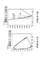
図31Aは、半値幅hwbが50nm、ピーク波長λpbがそれぞれ420nm,450nm、460nmの青色発光ダイオード21B、3つの色度点をxy色度図中にプロットした図であり、図31Bは、プロットされた色度点を拡大して示した図である。これによると、NTSC比100%以上を達成していないピーク波長λprが460nmの青色発光ダイオード21Bの色度点は、上述した図24Bを参照して規定された青色発光ダイオード21Bの最適な色度点領域である領域BFから外れてしまっていることが分かる。
以上のことからも分かるように、NTSC比が100%以上を達成するために、単純にピーク波長範囲だけを規定した発光ダイオード21を用いた場合、スペクトル分布の影響が全く考慮されないため、表7、表8、表9で示したようにNTSC100%以上ではない発光ダイオード21をも含んでしまうことになる。これを、発光ダイオード21を個別に発光させた際に測定される色度範囲として規定することで、図29B、図30B、図31Bに示すように、NTSC比が100%以上とならない発光ダイオード21を除外することができる。
したがって、赤色発光ダイオード21R、緑色発光ダイオード21G、青色発光ダイオード21Bでそれぞれ発光される赤色光、緑色光、青色光の最適な色度範囲をそれぞれ、図13に示すように規定することで、カラー液晶表示装置100の色再現範囲を、極めて正確にNTSC比100%以上を達成できるような色再現範囲とすることができる。
なお、上述した説明においては、NTSC比で100%以上の色再現範囲をカラー液晶表示装置100が達成するために規定する発光ダイオード21の色度を、国際照明委員会(CIE:Commission Internationale de I'Eclariage)が定めたXYZ表色系のxy色度図で規定するようにしたが、例えば、変換式、u’=4x/(―2x+12y+3)、v’=9y/(―2x+12y+3)を用いることで、同じくCIEによって定められたu’v’色度図などにも適用することができる。つまり、本発明は、このような、色度図の違いなどに限定されるものではなく、変換可能などのような表色系、色度図に対しても適用することができる。
ところで、バックライト方式のカラー液晶表示装置は、バックライト光源に発光ダイオードを用いることにより、CCFLと比較して非常に色純度が高くなるため、色再現範囲を大幅に広げることができる。
しかしながら、発光ダイオードの発光スペクトルの半値幅が広いと、混色によって色純度が落ちるため、色再現範囲を充分に広げることができなくなる。
特に、緑色発光ダイオードのスペクトル分布は、他の青色発光ダイオードや赤色発光ダイオードのスペクトル分布と比較して広く、半値幅として他の発光ダイオードの2倍近い値を示す。これにより、緑色発光ダイオードの発光スペクトルが青色のカラーフィルタの透過波長帯域に重なって、色の漏れこみによる緑色と青色との混色が発生するために、色再現範囲の緑色の領域を充分に広げることができなかった。
ここで、半値幅とは、スペクトルのピークの高さ(強度)のちょうど半分の値(強度)におけるスペクトルの波長幅を意味している。
本発明が適用されるカラー液晶表示装置では、バックライト光源として、赤色発光ダイオード、緑色発光ダイオード、青色発光ダイオードから成る光源を用い、さらに発光ダイオードの発光スペクトルの半値幅を規定する。このように半値幅を規定することにより、隣接するカラーフィルタからの混色の影響が押さえられて、充分広い色域を確保することができる。
本実施に形態では、特に、スペクトル分布が他の発光ダイオードよりも広い緑色発光ダイオードの半値幅を規定する。これにより、緑色と他の色(特に青色)に対する影響(色の漏れこみによる混色等)を最小限に抑制することができ、色再現範囲の緑色の領域を広げることができる。
緑色発光ダイオードの発光スペクトルの半値幅を狭くするには、例えば、以下のように緑色発光ダイオードを構成すればよい。
緑色発光ダイオード用の結晶としては、ZnSe等のII−VI族化合物半導体や、GaN等のIII −V族化合物半導体等が使用されている。これらの化合物半導体の結晶は、成長方法として、MBE(分子線エピタキシー)法やMOCVD(有機金属化学的気相成長)法に代表されるエピタキシャル成長技術を採用することにより、良質な結晶が得られるようになった。
そして、従来よりも純度の高い結晶を得ることができれば、即ち、緑色発光ダイオードを構成する結晶の純度を上げることによって、発光スペクトルの半値幅を狭めることができる。これは、純度が高くなることにより、バンドギャップエネルギと発光ピークエネルギとの差が減少することに起因する。
したがって、結晶の成長方法を工夫することにより、純度の高い結晶を作製すれば、発光スペクトルの半値幅の狭い緑色発光ダイオードを構成することができる。
さらに好ましくは、XYZ表色計のxy色度図において、緑色の色度点(カラーポイント)が所定の範囲内にあるように、緑色発光ダイオードを構成する。具体的には、xy色度図の緑色の領域を拡大した図34において、破線で示す範囲内とする。即ち、XYZ表色計のxy色度図において、緑色発光ダイオードの色度点(カラーポイント)を、0.16≦x≦0.21、0.70≦y≦0.76の範囲内とする。
そして、色度点を上述した範囲内とすることにより、緑色の領域においてカラー液晶表示装置の色再現範囲を広げて、sRGB規格の領域を完全にカバーすると共に、NTSC比を100%以上と大きくすることができる。また、前述したsYCC規格の領域に対応させることも可能になる。
緑色発光ダイオードの発光スペクトルの半値幅FWHMは、狭いことにこしたことはないが、30nm未満にすることは、現状では製造上の問題から困難である。また、発光スペクトルの半値幅が極端に狭い構成とすると、スペクトルエネルギが減少するため、輝度の劣化にもつながることになる。
なお、製造上問題なく、発光スペクトルの半値幅が30nm未満のものを製造することが可能になれば、色域を広げるという観点から、30nm以上に制限されるものではない。
本実施に形態において、カラーフィルタとしては、従来広く使用されているカラーフィルタ、即ち、原色(赤色、緑色、青色)のフィルタや補色系(シアン、マゼンタ、イエロー)のフィルタを使用することができる。
また、本実施に形態において、使用する発光ダイオードの色の組み合わせは自由であるが、基本的には、3原色の発光ダイオード(赤色発光ダイオード、緑色発光ダイオード、青色発光ダイオード)を用いて、白色及び種々の色を再現する。
なお、3原色の発光ダイオードに、さらに別のダイオードを付加して、バックライト装置の光源を構成してもよい。
そして、各発光ダイオードからの光をバックライト装置の内部で混合させて、白色光とする。
ところで、本実施の形態のカラー液晶表示装置100では、特に、バックライト装置20の緑色発光ダイオード21Gを、発光スペクトルの半値幅FWHMが30nm〜40nmの範囲内である構成とする。
このように、緑色発光ダイオード21Gの発光スペクトルの半値幅FWHMを30nm〜40nmの範囲内とすることにより、半値幅FWHMが比較的狭くなることから、緑色発光ダイオード21Gの発光スペクトルの裾が短くなり、他の色、例えば青色フィルタCFBの透過波長帯域との重なりを少なくすることができる。これにより、緑色と他の色(特に青色)との混色を抑制することができる。
ここで、実際にカラー液晶表示装置を作製して、その特性を調べた。図32に概略図を示すように、カラー液晶表示装置100のカラーフィルタ19の上方に、色彩輝度計300を配置して、分光特性の測定を行った。また、分光特性をXYZ表色系色度図にプロットして、このXYZ表色系色度図からNTSC比を求めた。
そして、発光スペクトルの半値幅FWHMが異なる緑色発光ダイオードを使用して、バックライト光源を3原色の発光ダイオードとし、通常使用されているカラーフィルタを用いて、それぞれのカラー液晶表示装置を作製して、上述した測定方法により、分光特性を測定した。
具体的には、3原色の発光ダイオードとして、発光ピーク波長が450nmで半値幅FWHMが25nmである青色発光ダイオード(LED−B)と、緑色発光ダイオード(LED−G)と、発光ピーク波長が640nmで半値幅FWHMが22nmである赤色発光ダイオード(LED−R)とを用いて、バックライト光源を構成し、このバックライト光源と通常使用されている3原色のカラーフィルタ(CFR,CFG,CFB)と組み合わせて、カラー液晶表示装置を構成した。
緑色発光ダイオード(LED−G)は、発光ピーク波長が525nmで半値幅FWHMが40nmであるものと、発光ピーク波長が525nmで半値幅FWHMが35nmであるものと、発光ピーク波長が525nmで半値幅FWHMが30nmであるものとの合計3種類を用意して、それぞれカラー液晶表示装置を作製した。
なお、各緑色発光ダイオード(LED−G)は、半値幅FWHMの変更に対応して、ホワイトバランスを合わせるように、スペクトル強度を変えて調整した。具体的には、3色の発光ダイオードを混色した白色光の色度座標が(x、y)=(0.288,0.274)となるように緑色発光ダイオードのスペクトル強度を調整した。
これら3種類の緑色発光ダイオードの発光スペクトルを重ねて、図33に示す。図33より、半値幅FWMMが狭いほど、ピーク強度が高く、ピークの裾が短くなっていることが分かる。
また、これら3種類の緑色発光ダイオード単体の色度点を、先に説明した図34上にプロットして示す。図34より、いずれの緑色発光ダイオードの場合も、色度点が破線で囲んだ領域内にあることが分かる。
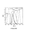
また、各色(赤色、青色、緑色)の発光ダイオードの発光スペクトルと、カラーフィルタの分光特性とを重ねて、図35に示す。緑色発光ダイオードLED−Gについては、図33に示した3種類の構成の発光スペクトルを重ねて表示している。
そして、測定結果として、それぞれのカラー液晶表示装置の色再現範囲をXYZ表色系色度図中に重ねて図36に示す。図36より、緑色発光ダイオードLED−Gの半値幅FWHMが狭くなると、色再現範囲が図中上方に広がることが分かる。これは、図35から分かるように、緑色発光ダイオードLED−Gの半値幅FWHMが狭くなるほど、カラーフィルタの青色フィルタCFBからの色混合が減少するためであると考えられる。
この図36に示した測定結果から、それぞれのカラー液晶表示装置の色再現範囲のNTSC比を求めたところ、緑色発光ダイオードLED−Gの発光スペクトルの半値幅FWMHが、40nmの場合はNTSC比が105%となり、35nmの場合はNTSC比が108%となり、30nmの場合はNTSC比が111%となった。
ここで、図36の青色の領域の拡大図を図37Aに示し、緑色の領域の拡大図を図37Bに示す。
図37Aより、青色の領域では、緑色発光ダイオードLED−Gの半値幅FWHMが変化しても、色度点の変化はほとんど見られない。一方、図37Bより、緑色の領域では、緑色発光ダイオードLED−Gの半値幅FWHMが狭くなるにつれて、図37B中矢印で示すように、y値が増加していき、緑色の色域が広くなることが認められた。
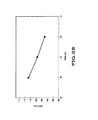
また、緑色発光ダイオードLED−Gの発光スペクトルの半値幅FWHMと、NTSC比との関係を、図38に示す。
図38より、半値幅と色域(NTSC比)とに相関があることが分かった。この関係より、NTSC比を105%以上維持するには、半値幅FWHMを40nm以下とする必要があり、40nmを超えるとNTSC比が105%を達成できないことが分かる。
そして、ディスプレイの色域を広くするためには、発光ダイオードの発光波長を最適化することだけでなく、発光スペクトルの半値幅を狭くすることも重要であることが分かった。
上述の本実施の形態のカラー液晶表示装置100の構成によれば、3原色の発光ダイオード21R,21G,21Bによりバックライト装置20の光源を構成し、緑色発光ダイオード21Gとして、スペクトルの半値幅FWHMが30nm〜40nmであるものを用いることにより、緑色と他の色との混色を抑制し、緑色の領域の色再現範囲を広くすることができる。これにより、NTSC比を100%以上と高くしたり、sYCC規格の領域に対応させたりすることも可能になる。
なお、本発明は、図面を参照して説明した上述の実施例に限定されるものではなく、添付の請求の範囲及びその主旨を逸脱することなく、様々な変更、置換又はその同等のものを行うことができることは当業者にとって明らかである。
Hereinafter, embodiments of the present invention will be described in detail with reference to the drawings. It goes without saying that the present invention is not limited to the following examples and can be arbitrarily changed without departing from the gist of the present invention.
The present invention is applied to, for example, a backlight type color liquid
As shown in FIG. 4, the transmissive color liquid
In the transmissive color liquid
Next, the
In this color liquid
The
The optical function sheet group has, for example, a function of decomposing incident light into orthogonal polarization components, a function of compensating for a phase difference of light waves to widen a viewing angle and preventing coloring, a function of diffusing incident light, and a brightness improvement The sheet is composed of a sheet having functions and the like, and is provided for converting the light emitted from the
FIG. 6 shows a schematic configuration diagram of the
As shown in FIG. 6, the
The light emitting diode units 21n are arranged in a plurality of rows in the
As shown in FIG. 6, the light emitting diode unit 21n may be arranged in the
The method of arranging the light emitting diode unit 21n so that the longitudinal direction is the horizontal direction or the vertical direction is the same as the CCFL arrangement method used as the light source of the conventional backlight device. The designed design know-how can be used, and the cost and time required for manufacturing can be shortened.
Light emitted from the red
In addition, although not shown in the figure, the
The white light that has been mixed and emitted from the
The color liquid
The driving
In the
Further, the
The backlight
The
For example, when the user adjusts the brightness from the
The color liquid
Although not shown, the color liquid
In the color liquid
In order to increase the color purity of display light through the color liquid
For example, the transmission wavelength band of the red filter CFR is shifted to the longer wavelength side so that the green light emitted by the green
Further, as the transmission wavelength band of the red filter CFR is shifted to the longer wavelength side and the blue filter CFB is shifted to the shorter wavelength side, the peak wavelength of the red light emitted from the red
Thus, in order to increase color purity and widen the color gamut, the transmission wavelength bands of the red filter CFR, the green filter CFG, and the blue filter CFB and the peak wavelengths of the red
Further, the sensitivity (luminosity) of human eyes to light varies depending on the wavelength, and as shown in FIG. 9, it takes a peak at 555 nm and becomes lower as the wavelength becomes longer and shorter. FIG. 9 is a relative visibility curve with 555 nm at which the visibility reaches a peak being 1.
Accordingly, if the peak wavelength of red light emitted from the red
Therefore, the peak wavelength of the red light emitted from the red
{About half width}
Regarding the light-emitting
Therefore, the spectrum distribution shape can be roughly specified by using the half width of the spectrum distribution called PW (Pulse Width) 50 or FWHM (Full Width at Half Maximum). For example, as the half-value width of each color light emitted from the
In particular, as can be seen from the specific luminous efficiency curve shown in FIG. 9, since the visibility of green light is very high, the half-value width of green light emitted by the green
In this way, the half-value width of each color light can roughly specify the spectral distribution shape that cannot be limited only by the peak wavelength, and thus defines the optimal chromaticity point range for increasing color purity and widening the color gamut. In some cases it is a very important value. Therefore, the red light, green light, and blue light emitted by the red
{Measurement 1}
First, in order to obtain the optimum range of the half width, the red
At this time, assuming that the half-value width hwr of red light is 22 nm, the half-value width hwg of green light is 37 nm, and the half-value width of blue light is 25 nm, the spectral characteristics of the
In addition to the NTSC color reproduction range, FIG. 11 also shows an sRGB standard color reproduction range defined by the International Electro-technical Commission (IEC) as a standard color space for computer displays.
In the subsequent measurement, the red
Table 1
{Measurement 2}
Subsequently, in the case where the peak wavelength interval between the green
As can be seen from FIG. 10, the interval (peak wavelength interval) between the peak wavelength of green light and the peak wavelength of blue light that achieves an NTSC ratio of 100% or more (peak wavelength interval) is the peak wavelength of red light and that of green light. It is narrower than the peak wavelength interval.
This is because, for example, when the half-value width of green light is widened to ensure luminance, the proportion of green light that passes through the transmission wavelength band of the blue filter CFB increases, so color mixing occurs and color purity decreases. This suggests that the color gamut will be narrowed. Therefore, even when the peak wavelength of green light and the peak wavelength of blue light are close to each other, the upper limit of the half-value width of green light can be found by obtaining the half-value width of green light that is 100% or more of the NTSC ratio.
Specifically, the peak wavelengths of the green
The spectral characteristics of the
Table 2
FIG. 14 shows the half-value width dependence of green light on the NTSC ratio obtained for the light transmitted through the color liquid
As described above, in
{Measurement 3}
In
The conditions of the
Table 3
Table 4
In FIG. 15, after passing through the color liquid
{Measurement 4}
As described above, the half-value width of the light-emitting
Specifically, in
The conditions of the
Table 5
The spectral characteristics of the
Further, FIG. 18 shows the half-value width dependence of green light on the NTSC ratio obtained for the light transmitted through the color liquid
The half-value width of the red light emitted from the red
In this way, the half-value widths of red light, green light, and blue light emitted by the red
As a result, not only the peak wavelength range but also the spectral distribution difference of each color light is taken into consideration, so that the color reproduction range of the color liquid
When the color liquid
Hereinafter, the red
Specifically, the peak wavelengths of the two light emitting diodes are fixed, and several remaining light emitting diodes having different peak wavelengths are prepared, and the NTSC (National Television System Committee) at that time is replaced while replacing them. The wavelength band when the NTSC ratio exceeds 100% is set to the optimum peak wavelength band in which the red
{Red
First, the peak wavelengths of the blue
FIG. 19A is a diagram showing the spectral characteristics of the
FIG. 19B shows a red
Therefore, the optimum peak wavelength band of the red
The half-value widths hwr, hwg, and hwb of the red light, green light, and blue light emitted from the red
{Green
Next, the peak wavelengths of the red
FIG. 20A shows the spectral characteristics of the
FIG. 20B shows a green
Therefore, the optimum peak wavelength band of the green
The half-value widths hwr, hwg, and hwb of the red light, green light, and blue light emitted from the red
{Blue
Subsequently, the peak wavelength of the red
FIG. 21A is a diagram showing the spectral characteristics of the
FIG. 21B shows the result of measuring the NTSC ratio when using a blue light emitting diode 21BN having a peak wavelength of (410 + 10N) nm. As shown in FIG. 21B, blue
Therefore, the optimum peak wavelength band of the blue
The half-value widths hwr, hwg, and hwb of the red light, green light, and blue light emitted from the red
Thus, the red light emitted from the red
{About chromaticity points}
As described above, the optimum peak wavelength band of the light-emitting
So far, the color gamut has been optimized by specifying the peak wavelength of the
Therefore, as described above, the chromaticity points of the red
In this way, the XYZ color system defined by the International Commission on Illumination (CIE) defines the chromaticity points of the red
{Chromaticity point of red
22A is a diagram in which the red
{Chromaticity point of green
FIG. 23A is a diagram in which three chromaticity points are plotted in an xy chromaticity diagram with peak wavelengths of 510 nm, 525 nm, and 535 nm, respectively, and FIG. 23B is an enlarged view of the plotted chromaticity points. FIG. Therefore, the peak wavelength of the green
{Chromaticity point of blue
FIG. 24A is a diagram in which the blue
Table 6
{Verification of differences in chromaticity points due to differences in spectral distribution}
Subsequently, as described above, even when the peak wavelengths are the same, it will be verified that the chromaticity point changes if the spectral distribution is different. For example, when the spectral distribution of a light emitting diode that emits color light of a certain peak wavelength becomes wide, light transmitted through the color liquid
25, 26, and 27 show the spectral characteristics of two types of light-emitting
When the spectral characteristics shown in FIG. 25, FIG. 26, and FIG. 27 and the spectral characteristics of the
Thus, since the color gamut is affected if the spectral distribution is different, the white light that illuminates the color liquid
The results of measuring the NTSC ratio under the conditions described above for the
Table 7
Table 8
Table 9
Table 7 shows the NTSC ratio of the red
Table 8 shows the NTSC ratio of the green light-emitting
Table 9 shows the NTSC ratio of the blue light-emitting
Backlights obtained by removing the color liquid
Results of plotting the chromaticity points of the red
{Chromaticity point of red
FIG. 29A is a diagram in which a red
{Chromaticity point of green
FIG. 30A is a graph in which three green chromaticity points are plotted in an xy chromaticity diagram with a half-value width hwg of 80 nm and peak wavelengths λpr of 510 nm, 525 nm, and 535 nm, respectively, and FIG. 30B is a plot. It is the figure which expanded and showed the made chromaticity point. According to this, the chromaticity point of the green
{Chromaticity point of blue
FIG. 31A is a diagram in which three chromaticity points are plotted in an xy chromaticity diagram with a half-value width hwb of 50 nm and a peak wavelength λpb of 420 nm, 450 nm, and 460 nm, respectively, and three chromaticity points plotted in FIG. 31B. It is the figure which expanded and showed the chromaticity point. According to this, the chromaticity point of the blue
As can be seen from the above, in order to achieve the NTSC ratio of 100% or more, when the
Accordingly, the optimum chromaticity ranges of red light, green light, and blue light emitted by the red
In the above description, the chromaticity of the
By the way, in the backlight type color liquid crystal display device, since the color purity is very high as compared with CCFL by using the light emitting diode as the backlight light source, the color reproduction range can be greatly expanded.
However, if the half-value width of the emission spectrum of the light emitting diode is wide, the color purity is lowered due to the color mixture, so that the color reproduction range cannot be sufficiently expanded.
In particular, the spectral distribution of the green light-emitting diode is wider than that of other blue light-emitting diodes and red light-emitting diodes, and the half-value width is nearly twice that of the other light-emitting diodes. As a result, the emission spectrum of the green light emitting diode overlaps with the transmission wavelength band of the blue color filter, and color mixture of green and blue due to color leakage occurs, so the green region of the color reproduction range is sufficiently expanded. I couldn't.
Here, the half-value width means the wavelength width of the spectrum at a value (intensity) that is exactly half the height (intensity) of the spectrum peak.
In a color liquid crystal display device to which the present invention is applied, a light source composed of a red light emitting diode, a green light emitting diode, and a blue light emitting diode is used as a backlight light source, and the half width of the light emission spectrum of the light emitting diode is defined. By defining the half-value width in this way, the influence of color mixing from adjacent color filters is suppressed, and a sufficiently wide color gamut can be secured.
In the present embodiment, in particular, the half-value width of the green light emitting diode whose spectral distribution is wider than that of other light emitting diodes is defined. As a result, the influence on green and other colors (especially blue) (such as color mixture due to color leakage) can be minimized, and the green region of the color reproduction range can be expanded.
In order to narrow the half-value width of the emission spectrum of the green light emitting diode, for example, the green light emitting diode may be configured as follows.
As a crystal for a green light emitting diode, a II-VI group compound semiconductor such as ZnSe or a III-V group compound semiconductor such as GaN is used. These compound semiconductor crystals can be obtained by adopting an epitaxial growth technique represented by MBE (molecular beam epitaxy) or MOCVD (metal organic chemical vapor deposition) as a growth method. Became.
If a crystal with higher purity than before can be obtained, that is, by increasing the purity of the crystal constituting the green light emitting diode, the half width of the emission spectrum can be narrowed. This is due to the fact that the difference between the band gap energy and the emission peak energy decreases as the purity increases.
Therefore, if a crystal with high purity is produced by devising a crystal growth method, a green light-emitting diode having a narrow half-width of the emission spectrum can be formed.
More preferably, the green light emitting diode is configured so that the green chromaticity point (color point) is within a predetermined range in the xy chromaticity diagram of the XYZ colorimeter. Specifically, it is within the range indicated by the broken line in FIG. 34 in which the green region of the xy chromaticity diagram is enlarged. That is, in the xy chromaticity diagram of the XYZ colorimeter, the chromaticity point (color point) of the green light emitting diode is in the range of 0.16 ≦ x ≦ 0.21 and 0.70 ≦ y ≦ 0.76. .
By setting the chromaticity point within the above-described range, the color reproduction range of the color liquid crystal display device is expanded in the green region to completely cover the sRGB standard region, and the NTSC ratio is as large as 100% or more. can do. It is also possible to correspond to the above-described sYCC standard area.
The half-value width FWHM of the emission spectrum of the green light emitting diode has never been narrow, but it is difficult to make it less than 30 nm at present due to manufacturing problems. Further, when the half-value width of the emission spectrum is extremely narrow, the spectrum energy is reduced, which leads to deterioration of luminance.
In addition, if it becomes possible to manufacture the thing whose half width of an emission spectrum is less than 30 nm without a problem on manufacture, from a viewpoint of extending a color gamut, it will not be restrict | limited to 30 nm or more.
In this embodiment, as the color filter, a color filter that has been widely used, that is, a primary color (red, green, blue) filter or a complementary color (cyan, magenta, yellow) filter can be used. .
In this embodiment, the color combinations of the light emitting diodes to be used are arbitrary. Basically, the light emitting diodes of the three primary colors (red light emitting diode, green light emitting diode, blue light emitting diode) are used, and white light is used. And reproduce various colors.
Note that another light emitting diode may be added to the three primary color light emitting diodes to constitute the light source of the backlight device.
And the light from each light emitting diode is mixed inside a backlight apparatus, and it is set as white light.
By the way, in the color liquid
In this way, by setting the half-value width FWHM of the emission spectrum of the green light-emitting
Here, a color liquid crystal display device was actually fabricated and its characteristics were examined. As shown schematically in FIG. 32, a
Then, using green light emitting diodes having different half-value widths FWHM of emission spectra, the backlight light source is a light emitting diode of three primary colors, and each color liquid crystal display device is manufactured using a color filter that is normally used. The spectral characteristics were measured by the measurement method described above.
Specifically, as light emitting diodes of three primary colors, a blue light emitting diode (LED-B) having a light emission peak wavelength of 450 nm and a half width FWHM of 25 nm, a green light emitting diode (LED-G), and a light emission peak wavelength of 640 nm. In addition, a red light emitting diode (LED-R) having a half-value width FWHM of 22 nm is used to form a backlight light source, and this backlight light source and commonly used three primary color filters (CFR, CFG, CFB) In combination, a color liquid crystal display device was constructed.
The green light emitting diode (LED-G) has an emission peak wavelength of 525 nm and a half-value width FWHM of 40 nm, an emission peak wavelength of 525 nm and a half-value width FWHM of 35 nm, and an emission peak wavelength of 525 nm and a half-value width. A total of three types having a FWHM of 30 nm were prepared, and a color liquid crystal display device was produced.
Each green light emitting diode (LED-G) was adjusted by changing the spectrum intensity so as to match the white balance in accordance with the change of the half-value width FWHM. Specifically, the spectral intensity of the green light emitting diode was adjusted so that the chromaticity coordinates of the white light mixed with the light emitting diodes of three colors were (x, y) = (0.288, 0.274).
The emission spectra of these three types of green light emitting diodes are superimposed and shown in FIG. From FIG. 33, it can be seen that the narrower the full width at half maximum FWMM, the higher the peak intensity and the shorter the tail of the peak.
Also, the chromaticity points of these three types of green light emitting diodes are plotted on the above-described FIG. From FIG. 34, it can be seen that in any of the green light emitting diodes, the chromaticity point is within the region surrounded by the broken line.
In addition, FIG. 35 shows the emission spectrum of each color (red, blue, green) light emitting diode and the spectral characteristic of the color filter in an overlapping manner. For the green light emitting diode LED-G, the emission spectra of the three types of configurations shown in FIG. 33 are displayed in an overlapping manner.
As a measurement result, the color reproduction range of each color liquid crystal display device is shown in FIG. 36 superimposed on the XYZ color system chromaticity diagram. From FIG. 36, it can be seen that when the half-value width FWHM of the green light emitting diode LED-G is narrowed, the color reproduction range expands upward in the figure. As can be seen from FIG. 35, it is considered that the color mixture from the blue filter CFB of the color filter decreases as the half-value width FWHM of the green light emitting diode LED-G becomes narrower.
From the measurement results shown in FIG. 36, the NTSC ratio of the color reproduction range of each color liquid crystal display device was obtained. When the half-value width FWMH of the emission spectrum of the green light emitting diode LED-G was 40 nm, the NTSC ratio was In the case of 35 nm, the NTSC ratio was 108%, and in the case of 30 nm, the NTSC ratio was 111%.
Here, an enlarged view of the blue region of FIG. 36 is shown in FIG. 37A, and an enlarged view of the green region is shown in FIG. 37B.
From FIG. 37A, in the blue region, even if the half-value width FWHM of the green light emitting diode LED-G changes, the change in the chromaticity point is hardly seen. On the other hand, as shown in FIG. 37B, in the green region, as the half-value width FWHM of the green light emitting diode LED-G becomes narrower, the y value increases and the green color gamut becomes wider as indicated by the arrow in FIG. It was recognized that
Moreover, the relationship between the half value width FWHM of the emission spectrum of green light emitting diode LED-G and NTSC ratio is shown in FIG.
From FIG. 38, it was found that there is a correlation between the half width and the color gamut (NTSC ratio). From this relationship, in order to maintain the NTSC ratio of 105% or more, it is necessary to set the full width at half maximum FWHM to 40 nm or less, and when it exceeds 40 nm, the NTSC ratio cannot be achieved to 105%.
And in order to widen the color gamut of a display, it turned out not only to optimize the light emission wavelength of a light emitting diode but to narrow the half value width of a light emission spectrum.
According to the configuration of the color liquid
The present invention is not limited to the above-described embodiments described with reference to the drawings, and various modifications, substitutions or equivalents thereof can be made without departing from the scope and spirit of the appended claims. It will be apparent to those skilled in the art that this can be done.
Claims (8)
当該バックライト装置は、半値幅hwrが、15nm≦hwr≦30nmである赤色光を発光する赤色発光ダイオード、半値幅hwgが、25nm≦hwg≦50nmである緑色光を発光する緑色発光ダイオード及び半値幅hwbが、15nm≦hwb≦30nmである青色光を発光する青色発光ダイオードからなる光源と、
上記光源から発光された赤色光、緑色光及び青色光を混色して、上記白色光とする混色手段と
を備えることを特徴とするバックライト装置。1. A backlight device for illuminating a transmissive color liquid crystal display panel having a color filter composed of three primary color filters that selectively transmit red light, green light, and blue light with white light from the back side,
The backlight device includes a red light emitting diode that emits red light having a half width hwr of 15 nm ≦ hwr ≦ 30 nm, a green light emitting diode that emits green light having a half width hwg of 25 nm ≦ hwg ≦ 50 nm, and a half width. a light source comprising a blue light emitting diode that emits blue light with hwb of 15 nm ≦ hwb ≦ 30 nm;
A backlight device comprising: color mixing means for mixing red light, green light, and blue light emitted from the light source into the white light.
上記バックライト装置は、半値幅hwrが、15nm≦hwr≦30nmである赤色光を発光する赤色発光ダイオード、半値幅hwgが、25nm≦hwg≦50nmである緑色光を発光する緑色発光ダイオード及び半値幅hwbが、15nm≦hwb≦30nmである青色光を発光する青色発光ダイオードからなる光源と、
上記光源から発光された赤色光、緑色光及び青色光を混色して、上記白色光とする混色手段と
を有することを特徴とするカラー液晶表示装置。3. A transmissive color liquid crystal display panel including a color filter including three primary color filters that selectively transmits red light, green light, and blue light; and a backlight device that illuminates the color liquid crystal display panel with white light from the back side; A color liquid crystal display device comprising:
The backlight device includes a red light emitting diode that emits red light having a half width hwr of 15 nm ≦ hwr ≦ 30 nm, a green light emitting diode that emits green light having a half width hwg of 25 nm ≦ hwg ≦ 50 nm, and a half width. a light source comprising a blue light emitting diode that emits blue light with hwb of 15 nm ≦ hwb ≦ 30 nm;
A color liquid crystal display device comprising: color mixing means for mixing red light, green light, and blue light emitted from the light source into white light.
当該バックライト装置は、国際照明委員会(CIE:Commission Internationale de I'Eclariage)が定めたXYZ表色系のxy色度図中における色度点が0.65≦x≦0.75、0.27≦y≦0.33となる赤色光を発光する赤色発光ダイオード、上記xy色度図中の色度点が0.12≦x≦0.28、0.64≦y≦0.76である緑色光を発光する緑色発光ダイオード及び上記xy色度図中の色度点が0.14≦x≦0.17、0.01≦y≦0.06となる青色光を発光する青色発光ダイオードとからなる光源と、
上記光源から発光された赤色光、緑色光及び青色光を混色して、上記白色光とする混色手段と
を備えることを特徴とするバックライト装置。5. A backlight device that illuminates a transmissive color liquid crystal display panel having a color filter including three primary color filters that selectively transmit red light, green light, and blue light with white light from the back side,
The backlight device has chromaticity points in the xy chromaticity diagram of the XYZ color system defined by the Commission Internationale de I'Eclariage (CIE: 0.65 ≦ x ≦ 0.75, 0.00). Red light-emitting diode that emits red light satisfying 27 ≦ y ≦ 0.33, and the chromaticity points in the xy chromaticity diagram are 0.12 ≦ x ≦ 0.28 and 0.64 ≦ y ≦ 0.76 A green light emitting diode emitting green light, and a blue light emitting diode emitting blue light with chromaticity points in the xy chromaticity diagram of 0.14 ≦ x ≦ 0.17 and 0.01 ≦ y ≦ 0.06, A light source consisting of
A backlight device comprising: color mixing means for mixing red light, green light, and blue light emitted from the light source into the white light.
上記バックライト装置は、国際照明委員会(CIE:Commission Internationale de I'Eclariage)が定めたXYZ表色系のxy色度図中における色度点が0.65≦x≦0.75、0.27≦y≦0.33となる赤色光を発光する赤色発光ダイオード、上記xy色度図中の色度点が0.12≦x≦0.28、0.64≦y≦0.76である緑色光を発光する緑色発光ダイオード及び上記xy色度図中の色度点が0.14≦x≦0.17、0.01≦y≦0.06となる青色光を発光する青色発光ダイオードとからなる光源と、
上記光源から発光された赤色光、緑色光及び青色光を混色して、上記白色光とする混色手段と
を備えることを特徴とするカラー液晶表示装置。6). A transmissive color liquid crystal display panel including a color filter including three primary color filters that selectively transmits red light, green light, and blue light; and a backlight device that illuminates the color liquid crystal display panel with white light from the back side; A color liquid crystal display device comprising:
The backlight device has chromaticity points of 0.65 ≦ x ≦ 0.75, 0.00 in the xy chromaticity diagram of the XYZ color system defined by the International Lighting Commission (CIE). Red light-emitting diode that emits red light satisfying 27 ≦ y ≦ 0.33, and the chromaticity points in the xy chromaticity diagram are 0.12 ≦ x ≦ 0.28 and 0.64 ≦ y ≦ 0.76 A green light emitting diode emitting green light, and a blue light emitting diode emitting blue light with chromaticity points in the xy chromaticity diagram of 0.14 ≦ x ≦ 0.17 and 0.01 ≦ y ≦ 0.06, A light source consisting of
A color liquid crystal display device comprising: color mixing means for mixing red light, green light, and blue light emitted from the light source into the white light.
前記カラー液晶表示パネルを背面側から照明する液晶表示用バックライト光源とを備え、
前記バックライト光源は、赤色発光ダイオード、緑色発光ダイオード、青色発光ダイオードから成り、前記バックライト光源から発光された赤色光、緑色光、青色光を混色して白色光とする混色手段を備え、
前記緑色発光ダイオードの発光スペクトルの半値幅が、30nm〜40nmの範囲内であることを特徴とするカラー液晶表示装置。7). A transmissive color liquid crystal display panel with a color filter;
A backlight source for liquid crystal display that illuminates the color liquid crystal display panel from the back side;
The backlight light source includes a red light emitting diode, a green light emitting diode, and a blue light emitting diode, and includes a color mixing unit that mixes red light, green light, and blue light emitted from the backlight light source to form white light,
A color liquid crystal display device, wherein a half-value width of an emission spectrum of the green light emitting diode is in a range of 30 nm to 40 nm.
8). In the xy chromaticity diagram of the XYZ colorimeter, the chromaticity point (color point) of the green light emitting diode is in the range of 0.16 ≦ x ≦ 0.21 and 0.70 ≦ y ≦ 0.76. The color liquid crystal display device according to claim 7, wherein:
Applications Claiming Priority (7)
| Application Number | Priority Date | Filing Date | Title |
|---|---|---|---|
| JP2004238789 | 2004-08-18 | ||
| JP2004238787 | 2004-08-18 | ||
| JP2004238787 | 2004-08-18 | ||
| JP2004238789 | 2004-08-18 | ||
| JP2005075500 | 2005-03-16 | ||
| JP2005075500 | 2005-03-16 | ||
| PCT/JP2005/014599 WO2006019016A1 (en) | 2004-08-18 | 2005-08-09 | Backlight device and color liquid crystal display device |
Publications (1)
| Publication Number | Publication Date |
|---|---|
| JPWO2006019016A1 true JPWO2006019016A1 (en) | 2008-05-08 |
Family
ID=35907405
Family Applications (1)
| Application Number | Title | Priority Date | Filing Date |
|---|---|---|---|
| JP2006531665A Pending JPWO2006019016A1 (en) | 2004-08-18 | 2005-08-09 | Backlight device and color liquid crystal display device |
Country Status (6)
| Country | Link |
|---|---|
| US (1) | US7663714B2 (en) |
| EP (1) | EP1788423A4 (en) |
| JP (1) | JPWO2006019016A1 (en) |
| KR (1) | KR20070043007A (en) |
| TW (1) | TW200617525A (en) |
| WO (1) | WO2006019016A1 (en) |
Cited By (1)
| Publication number | Priority date | Publication date | Assignee | Title |
|---|---|---|---|---|
| JP2012069572A (en) * | 2010-09-21 | 2012-04-05 | Panasonic Corp | Light-emitting module, backlight device and display device |
Families Citing this family (65)
| Publication number | Priority date | Publication date | Assignee | Title |
|---|---|---|---|---|
| TWI289708B (en) | 2002-12-25 | 2007-11-11 | Qualcomm Mems Technologies Inc | Optical interference type color display |
| US7342705B2 (en) | 2004-02-03 | 2008-03-11 | Idc, Llc | Spatial light modulator with integrated optical compensation structure |
| US7355780B2 (en) * | 2004-09-27 | 2008-04-08 | Idc, Llc | System and method of illuminating interferometric modulators using backlighting |
| US7750886B2 (en) | 2004-09-27 | 2010-07-06 | Qualcomm Mems Technologies, Inc. | Methods and devices for lighting displays |
| US7561323B2 (en) * | 2004-09-27 | 2009-07-14 | Idc, Llc | Optical films for directing light towards active areas of displays |
| KR101171182B1 (en) * | 2005-08-05 | 2012-08-06 | 삼성전자주식회사 | Back light unit and liquid crystal display using the same |
| US7603001B2 (en) * | 2006-02-17 | 2009-10-13 | Qualcomm Mems Technologies, Inc. | Method and apparatus for providing back-lighting in an interferometric modulator display device |
| GB0611126D0 (en) * | 2006-06-06 | 2006-07-19 | Liquavista Bv | Colour display device |
| JP2008052067A (en) * | 2006-08-25 | 2008-03-06 | Sony Corp | Light source device, display device and light emitting diode chip |
| US7845841B2 (en) * | 2006-08-28 | 2010-12-07 | Qualcomm Mems Technologies, Inc. | Angle sweeping holographic illuminator |
| US7855827B2 (en) | 2006-10-06 | 2010-12-21 | Qualcomm Mems Technologies, Inc. | Internal optical isolation structure for integrated front or back lighting |
| US8107155B2 (en) * | 2006-10-06 | 2012-01-31 | Qualcomm Mems Technologies, Inc. | System and method for reducing visual artifacts in displays |
| JP2010510530A (en) | 2006-10-06 | 2010-04-02 | クォルコム・メムズ・テクノロジーズ・インコーポレーテッド | Optical loss structure integrated into lighting equipment |
| EP1943551A2 (en) | 2006-10-06 | 2008-07-16 | Qualcomm Mems Technologies, Inc. | Light guide |
| WO2008045311A2 (en) * | 2006-10-06 | 2008-04-17 | Qualcomm Mems Technologies, Inc. | Illumination device with built-in light coupler |
| WO2008045463A2 (en) * | 2006-10-10 | 2008-04-17 | Qualcomm Mems Technologies, Inc. | Display device with diffractive optics |
| US7864395B2 (en) * | 2006-10-27 | 2011-01-04 | Qualcomm Mems Technologies, Inc. | Light guide including optical scattering elements and a method of manufacture |
| JP5050498B2 (en) * | 2006-11-21 | 2012-10-17 | ソニー株式会社 | Light source device, backlight device, liquid crystal display device, and method of manufacturing backlight device |
| KR100930171B1 (en) * | 2006-12-05 | 2009-12-07 | 삼성전기주식회사 | White light emitting device and white light source module using same |
| KR101385453B1 (en) * | 2007-05-02 | 2014-04-21 | 삼성디스플레이 주식회사 | Driving method of light source and back light assembly for carrying out the driving method |
| US9279079B2 (en) * | 2007-05-30 | 2016-03-08 | Sharp Kabushiki Kaisha | Method of manufacturing phosphor, light-emitting device, and image display apparatus |
| JP2009010315A (en) * | 2007-05-30 | 2009-01-15 | Sharp Corp | Method of manufacturing phosphor, light-emitting device and image display apparatus |
| JP5263722B2 (en) * | 2007-06-08 | 2013-08-14 | シャープ株式会社 | Phosphor, light emitting device, and image display device |
| US7905618B2 (en) | 2007-07-19 | 2011-03-15 | Samsung Led Co., Ltd. | Backlight unit |
| KR100951274B1 (en) * | 2007-07-19 | 2010-05-06 | 삼성엘이디 주식회사 | Back light unit |
| US8941631B2 (en) * | 2007-11-16 | 2015-01-27 | Qualcomm Mems Technologies, Inc. | Simultaneous light collection and illumination on an active display |
| US7949213B2 (en) * | 2007-12-07 | 2011-05-24 | Qualcomm Mems Technologies, Inc. | Light illumination of displays with front light guide and coupling elements |
| US8068710B2 (en) | 2007-12-07 | 2011-11-29 | Qualcomm Mems Technologies, Inc. | Decoupled holographic film and diffuser |
| US20090168459A1 (en) * | 2007-12-27 | 2009-07-02 | Qualcomm Incorporated | Light guide including conjugate film |
| WO2009099547A2 (en) * | 2008-01-30 | 2009-08-13 | Digital Optics International, Llc | Thin illumination system |
| US8721149B2 (en) | 2008-01-30 | 2014-05-13 | Qualcomm Mems Technologies, Inc. | Illumination device having a tapered light guide |
| WO2009102733A2 (en) * | 2008-02-12 | 2009-08-20 | Qualcomm Mems Technologies, Inc. | Integrated front light diffuser for reflective displays |
| WO2009102731A2 (en) | 2008-02-12 | 2009-08-20 | Qualcomm Mems Technologies, Inc. | Devices and methods for enhancing brightness of displays using angle conversion layers |
| US8654061B2 (en) * | 2008-02-12 | 2014-02-18 | Qualcomm Mems Technologies, Inc. | Integrated front light solution |
| JP5269455B2 (en) * | 2008-03-26 | 2013-08-21 | 富士フイルム株式会社 | Liquid crystal display |
| JP2011517118A (en) * | 2008-04-11 | 2011-05-26 | クォルコム・メムズ・テクノロジーズ・インコーポレーテッド | Methods for improving PV aesthetics and efficiency |
| WO2009129264A1 (en) | 2008-04-15 | 2009-10-22 | Qualcomm Mems Technologies, Inc. | Light with bi-directional propagation |
| US20090323144A1 (en) * | 2008-06-30 | 2009-12-31 | Qualcomm Mems Technologies, Inc. | Illumination device with holographic light guide |
| EP2350526B1 (en) * | 2008-10-10 | 2014-12-31 | Qualcomm Mems Technologies, Inc | Distributed illumination system |
| JP2012505518A (en) * | 2008-10-10 | 2012-03-01 | クォルコム・メムズ・テクノロジーズ・インコーポレーテッド | Distributed lighting control system |
| US20100157406A1 (en) * | 2008-12-19 | 2010-06-24 | Qualcomm Mems Technologies, Inc. | System and method for matching light source emission to display element reflectivity |
| EP2387690A1 (en) | 2009-01-13 | 2011-11-23 | Qualcomm Mems Technologies, Inc. | Large area light panel and screen |
| US20100195310A1 (en) * | 2009-02-04 | 2010-08-05 | Qualcomm Mems Technologies, Inc. | Shaped frontlight reflector for use with display |
| US8172417B2 (en) * | 2009-03-06 | 2012-05-08 | Qualcomm Mems Technologies, Inc. | Shaped frontlight reflector for use with display |
| EP2435865A1 (en) | 2009-05-29 | 2012-04-04 | Qualcomm Mems Technologies, Inc. | Illumination devices and methods of fabrication thereof |
| US20110032214A1 (en) * | 2009-06-01 | 2011-02-10 | Qualcomm Mems Technologies, Inc. | Front light based optical touch screen |
| CN102483485A (en) * | 2009-08-03 | 2012-05-30 | 高通Mems科技公司 | Microstructures For Light Guide Illumination |
| US9195097B2 (en) | 2010-08-03 | 2015-11-24 | Sharp Kabushiki Kaisha | Liquid crystal display device and process for producing liquid-crystal display device |
| US8402647B2 (en) | 2010-08-25 | 2013-03-26 | Qualcomm Mems Technologies Inc. | Methods of manufacturing illumination systems |
| US9644146B2 (en) | 2010-09-07 | 2017-05-09 | Sharp Kabushiki Kaisha | Composition for forming liquid crystal layer, liquid crystal display device, and method for producing liquid crystal display device |
| WO2012033014A1 (en) * | 2010-09-08 | 2012-03-15 | シャープ株式会社 | Liquid crystal display device |
| CN102062889A (en) * | 2010-11-12 | 2011-05-18 | 创维液晶器件(深圳)有限公司 | Method for manufacturing color filter, color filter and LED liquid crystal module |
| US9182632B2 (en) | 2010-12-06 | 2015-11-10 | Sharp Kabushiki Kaisha | Liquid crystal display device and method for manufacturing liquid crystal display device |
| US8902484B2 (en) | 2010-12-15 | 2014-12-02 | Qualcomm Mems Technologies, Inc. | Holographic brightness enhancement film |
| US9239493B2 (en) | 2010-12-22 | 2016-01-19 | Sharp Kabushiki Kaisha | Liquid crystal alignment agent, liquid crystal display, and method for manufacturing liquid crystal display |
| US20140111748A1 (en) * | 2011-06-07 | 2014-04-24 | Kozo Nakamura | Display device |
| CN102520571B (en) * | 2011-11-04 | 2014-08-06 | 深圳市光峰光电技术有限公司 | Light-emitting device and projection system |
| DE102012109104B4 (en) * | 2012-09-26 | 2021-09-09 | OSRAM Opto Semiconductors Gesellschaft mit beschränkter Haftung | Lighting device, backlighting for a display or a television and display or television |
| TWI483045B (en) * | 2013-06-20 | 2015-05-01 | Au Optronics Corp | Display |
| CN104423090B (en) * | 2013-08-27 | 2017-10-13 | 群创光电股份有限公司 | Display device |
| EP2988340B1 (en) * | 2014-08-18 | 2017-10-11 | Seoul Semiconductor Co., Ltd. | Light emitting diode package and manufacturing method thereof |
| KR102524805B1 (en) * | 2016-02-12 | 2023-04-25 | 삼성전자주식회사 | Lighting source module, display panel and display apparatus |
| JP6740762B2 (en) * | 2016-07-13 | 2020-08-19 | 日亜化学工業株式会社 | Light emitting device and manufacturing method thereof |
| TWI728873B (en) | 2020-07-21 | 2021-05-21 | 隆達電子股份有限公司 | Light-emitting diode device |
| US11294238B1 (en) | 2020-10-29 | 2022-04-05 | Lextar Electronics Corporation | Low blue light backlight module |
Family Cites Families (23)
| Publication number | Priority date | Publication date | Assignee | Title |
|---|---|---|---|---|
| JPH08263438A (en) * | 1994-11-23 | 1996-10-11 | Xerox Corp | Distribution and use control system of digital work and access control method to digital work |
| US5892900A (en) * | 1996-08-30 | 1999-04-06 | Intertrust Technologies Corp. | Systems and methods for secure transaction management and electronic rights protection |
| US7133846B1 (en) * | 1995-02-13 | 2006-11-07 | Intertrust Technologies Corp. | Digital certificate support system, methods and techniques for secure electronic commerce transaction and rights management |
| US7143290B1 (en) * | 1995-02-13 | 2006-11-28 | Intertrust Technologies Corporation | Trusted and secure techniques, systems and methods for item delivery and execution |
| US6658568B1 (en) * | 1995-02-13 | 2003-12-02 | Intertrust Technologies Corporation | Trusted infrastructure support system, methods and techniques for secure electronic commerce transaction and rights management |
| US6233684B1 (en) * | 1997-02-28 | 2001-05-15 | Contenaguard Holdings, Inc. | System for controlling the distribution and use of rendered digital works through watermaking |
| TW528169U (en) * | 2000-05-04 | 2003-04-11 | Koninkl Philips Electronics Nv | Assembly of a display device and an illumination system |
| AU7593601A (en) * | 2000-07-14 | 2002-01-30 | Atabok Inc | Controlling and managing digital assets |
| US7421411B2 (en) * | 2001-07-06 | 2008-09-02 | Nokia Corporation | Digital rights management in a mobile communications environment |
| JP3840940B2 (en) | 2001-09-28 | 2006-11-01 | 株式会社日立製作所 | Image display device |
| FR2832236B1 (en) * | 2001-11-13 | 2004-04-16 | Inst Nat Rech Inf Automat | SEMANTIC WEB PORTAL GRAPHIC INTERFACE |
| JP2003207770A (en) | 2002-01-15 | 2003-07-25 | Toppan Printing Co Ltd | Color filter for liquid crystal display and liquid crystal display using the same |
| JP2004093761A (en) | 2002-08-30 | 2004-03-25 | Toko Inc | Backlight unit |
| JP4611604B2 (en) * | 2002-09-30 | 2011-01-12 | 独立行政法人情報通信研究機構 | Image display device |
| US7526545B2 (en) * | 2003-01-17 | 2009-04-28 | Relevant Media Llc | Content distribution system |
| US7467399B2 (en) * | 2004-03-31 | 2008-12-16 | International Business Machines Corporation | Context-sensitive confidentiality within federated environments |
| US20060190290A1 (en) * | 2005-02-22 | 2006-08-24 | Brainshield Technologies, Inc. | Systems and methods for distributing electronic files |
| US20060277457A1 (en) * | 2005-06-07 | 2006-12-07 | Salkind Carole T | Method and apparatus for integrating video into web logging |
| EP1929685A4 (en) * | 2005-09-29 | 2011-12-21 | Contentguard Holdings Inc | System and method for digital rights management using advanced copy with issue rights, and managed copy tokens |
| US7954064B2 (en) * | 2005-10-27 | 2011-05-31 | Apple Inc. | Multiple dashboards |
| WO2007131132A2 (en) * | 2006-05-03 | 2007-11-15 | Voxant, Inc. | System and method for collecting and distributing content |
| US9002726B2 (en) * | 2006-06-19 | 2015-04-07 | Nokia Corporation | Advertising based on widgets |
| US20080040681A1 (en) * | 2006-08-11 | 2008-02-14 | Don Synstelien | System and Method for Automatically Updating a Widget on a Desktop |
-
2005
- 2005-08-09 JP JP2006531665A patent/JPWO2006019016A1/en active Pending
- 2005-08-09 WO PCT/JP2005/014599 patent/WO2006019016A1/en active Application Filing
- 2005-08-09 EP EP05770536A patent/EP1788423A4/en not_active Ceased
- 2005-08-09 KR KR1020077003848A patent/KR20070043007A/en not_active Application Discontinuation
- 2005-08-09 US US11/573,375 patent/US7663714B2/en active Active
- 2005-08-16 TW TW094127961A patent/TW200617525A/en not_active IP Right Cessation
Cited By (1)
| Publication number | Priority date | Publication date | Assignee | Title |
|---|---|---|---|---|
| JP2012069572A (en) * | 2010-09-21 | 2012-04-05 | Panasonic Corp | Light-emitting module, backlight device and display device |
Also Published As
| Publication number | Publication date |
|---|---|
| TW200617525A (en) | 2006-06-01 |
| KR20070043007A (en) | 2007-04-24 |
| WO2006019016A1 (en) | 2006-02-23 |
| US20070182887A1 (en) | 2007-08-09 |
| EP1788423A4 (en) | 2008-02-27 |
| EP1788423A1 (en) | 2007-05-23 |
| TWI332102B (en) | 2010-10-21 |
| US7663714B2 (en) | 2010-02-16 |
Similar Documents
| Publication | Publication Date | Title |
|---|---|---|
| JPWO2006019016A1 (en) | Backlight device and color liquid crystal display device | |
| JP4635551B2 (en) | Color liquid crystal display device | |
| US7789527B2 (en) | Backlight device and color liquid crystal display | |
| TWI261692B (en) | Color filter and color liquid crystal display device | |
| KR101237326B1 (en) | Backlight device and display device | |
| EP1804116B1 (en) | Color liquid crystal display | |
| JP4650085B2 (en) | Backlight device and liquid crystal display device | |
| JP4701806B2 (en) | Backlight device and liquid crystal display device | |
| CN100507676C (en) | Backlight device and color liquid crystal display apparatus | |
| JP2006284906A (en) | Backlight device and liquid crystal display device | |
| JP2005234133A (en) | Color filter for color liquid crystal display, and color liquid crystal display device | |
| KR101669642B1 (en) | Back light unit and sub array device of leds used for the same | |
| JP2005260116A (en) | Driving circuit of light-emitting element and picture image display device | |
| JP2005338290A (en) | Color liquid crystal display device |
Legal Events
| Date | Code | Title | Description |
|---|---|---|---|
| A621 | Written request for application examination |
Free format text: JAPANESE INTERMEDIATE CODE: A621 Effective date: 20080716 |
|
| A131 | Notification of reasons for refusal |
Free format text: JAPANESE INTERMEDIATE CODE: A131 Effective date: 20110510 |
|
| A521 | Request for written amendment filed |
Free format text: JAPANESE INTERMEDIATE CODE: A523 Effective date: 20110630 |
|
| A02 | Decision of refusal |
Free format text: JAPANESE INTERMEDIATE CODE: A02 Effective date: 20110726 |