JP7470539B2 - Construction history information management system - Google Patents
Construction history information management system Download PDFInfo
- Publication number
- JP7470539B2 JP7470539B2 JP2020048391A JP2020048391A JP7470539B2 JP 7470539 B2 JP7470539 B2 JP 7470539B2 JP 2020048391 A JP2020048391 A JP 2020048391A JP 2020048391 A JP2020048391 A JP 2020048391A JP 7470539 B2 JP7470539 B2 JP 7470539B2
- Authority
- JP
- Japan
- Prior art keywords
- data
- collected data
- server
- category
- history information
- Prior art date
- Legal status (The legal status is an assumption and is not a legal conclusion. Google has not performed a legal analysis and makes no representation as to the accuracy of the status listed.)
- Active
Links
- 238000010276 construction Methods 0.000 title claims description 42
- 238000012545 processing Methods 0.000 claims description 44
- 230000008859 change Effects 0.000 claims description 29
- 238000004891 communication Methods 0.000 claims description 28
- 238000012876 topography Methods 0.000 claims description 14
- 239000002689 soil Substances 0.000 claims description 11
- 238000000034 method Methods 0.000 description 74
- 230000008569 process Effects 0.000 description 68
- 238000007726 management method Methods 0.000 description 35
- 238000012937 correction Methods 0.000 description 27
- 238000004364 calculation method Methods 0.000 description 23
- 238000010586 diagram Methods 0.000 description 19
- 230000005540 biological transmission Effects 0.000 description 11
- 238000005070 sampling Methods 0.000 description 9
- 230000000694 effects Effects 0.000 description 8
- 230000006870 function Effects 0.000 description 5
- 230000002265 prevention Effects 0.000 description 5
- 230000009467 reduction Effects 0.000 description 5
- 239000000523 sample Substances 0.000 description 5
- 230000007246 mechanism Effects 0.000 description 4
- 239000004065 semiconductor Substances 0.000 description 4
- 238000013459 approach Methods 0.000 description 3
- 238000001514 detection method Methods 0.000 description 3
- 230000003111 delayed effect Effects 0.000 description 2
- 238000005516 engineering process Methods 0.000 description 2
- 238000004904 shortening Methods 0.000 description 2
- 230000001133 acceleration Effects 0.000 description 1
- 230000009471 action Effects 0.000 description 1
- 230000008901 benefit Effects 0.000 description 1
- FFBHFFJDDLITSX-UHFFFAOYSA-N benzyl N-[2-hydroxy-4-(3-oxomorpholin-4-yl)phenyl]carbamate Chemical compound OC1=C(NC(=O)OCC2=CC=CC=C2)C=CC(=C1)N1CCOCC1=O FFBHFFJDDLITSX-UHFFFAOYSA-N 0.000 description 1
- 230000037237 body shape Effects 0.000 description 1
- 238000005259 measurement Methods 0.000 description 1
- 238000012986 modification Methods 0.000 description 1
- 230000004048 modification Effects 0.000 description 1
- 230000003287 optical effect Effects 0.000 description 1
- 239000000047 product Substances 0.000 description 1
- 239000013589 supplement Substances 0.000 description 1
Images


Description
本発明は、各作業機械で収集された収集データを蓄積、管理する施工履歴情報管理システムに関する。 The present invention relates to a construction history information management system that accumulates and manages data collected by each work machine.
近年、作業機械による情報化施工の分野では、メーカやユーザなどの施工管理者の管理下にある複数の作業機械の施工履歴情報を蓄積するために、各作業機械に搭載されたセンサ等で収集された収集データ(作業機械の位置データ、作業機械の姿勢データ、作業機械が運搬した土量データ等)をサーバで蓄積・管理する施工履歴情報管理システムが活用されている。施工管理者は、施工履歴情報管理システムを活用することで、作業者、作業現場及び作業機械毎に施工履歴情報の収集データを効率良く蓄積することができる。 In recent years, in the field of information-based construction using work machines, construction history information management systems have been used to accumulate construction history information for multiple work machines under the management of construction managers such as manufacturers and users. These systems accumulate and manage data collected by sensors mounted on each work machine (such as work machine position data, work machine attitude data, and data on the amount of soil transported by the work machine) on a server. By utilizing the construction history information management system, construction managers can efficiently accumulate collected data on construction history information for each worker, work site, and work machine.
上記の施工履歴情報管理システムのようにサーバでデータを管理するシステムに関して、特許文献1は、複数の車両から送信されるプローブデータ(車両に搭載されたセンサ等で取得されるデータ)を受信するサーバが、受信したプローブデータに基づき、送信した車両の総数と、車両ごとのプローブデータのアップロード時刻とを検出し、検出したアップロード時刻に基づき、車両ごとに、車両の総数に応じたアップロード時刻の補正値を算出し、算出した補正値を、車両に対してそれぞれ送信することを開示している。
Regarding a system that manages data on a server, such as the above-mentioned construction history information management system,
ところで、施工履歴情報管理システムでは、サーバが各作業機械から収集したデータに基づいて各作業機械に送信するデータを新たに生成し、その生成したデータ(生成データ)を送信して各作業機械で利用することがある。例えばサーバが各作業機械から受信した収集データに基づいて各作業機械の制御指令データ(生成データ)を生成・送信して各作業機械を遠隔制御することがある。また、サーバが収集データに基づいて各作業機械の状態や施工履歴に関するデータを生成して施工管理者にモニタなどを介して提示することがある。これらのような場合、各作業機械のセンサ等で取得された収集データが速やかにサーバに受信されるとみなすと、当該収集データをサーバが受信した時刻と、当該収集データに基づいてサーバが新たにデータを生成した時刻と、生成された生成データをサーバが各作業機械に送信する時刻とは、各作業機械の制御精度や作業効率の観点からは、それぞれできるだけ近い方が好ましくリアルタイム性が要求される。 In a construction history information management system, the server may generate new data to be sent to each work machine based on data collected from each work machine, and transmit the generated data (generated data) to be used by each work machine. For example, the server may generate and transmit control command data (generated data) for each work machine based on collected data received from each work machine to remotely control each work machine. The server may also generate data related to the status and construction history of each work machine based on the collected data and present the data to the construction manager via a monitor or the like. In such cases, if it is assumed that collected data acquired by a sensor or the like of each work machine is promptly received by the server, it is preferable that the time when the server receives the collected data, the time when the server generates new data based on the collected data, and the time when the server transmits the generated data to each work machine are as close as possible from the viewpoint of the control accuracy and work efficiency of each work machine, and real-time performance is required.
しかし、複数の作業機械がサーバの管理下にある場合、各作業機械でのデータの取得タイミング(データ取得周期)や各作業機械からサーバへの送信タイミング(アップロード周期)は各作業機械で独立しており、他の作業機械の取得タイミングや送信タイミングを考慮して設定されていないことが通常である。そのため、各作業機械からの収集データが或る時間にサーバに集中し過ぎると、サーバ負荷(例えば演算処理装置の負荷)が増大する可能性がある。サーバ負荷の増大は、収集データの受信時刻から生成データの送信時刻までの時間の増加を意味し、サーバから各作業機械に送信される生成データの送信遅延に繋がるため、生成データの送信先の作業機械の制御精度や作業効率等が容易に低下し得る。 However, when multiple work machines are under the management of a server, the timing of data acquisition (data acquisition cycle) at each work machine and the timing of data transmission (upload cycle) from each work machine to the server are independent for each work machine, and are usually not set with consideration given to the acquisition and transmission timings of the other work machines. Therefore, if too much collected data from each work machine is concentrated on the server at a certain time, the server load (e.g., the load on the processing unit) may increase. An increase in server load means an increase in the time from the time the collected data is received to the time the generated data is transmitted, which leads to a delay in the transmission of the generated data transmitted from the server to each work machine, and can easily reduce the control accuracy and work efficiency of the work machine to which the generated data is transmitted.
特許文献1の技術は、各車両からのプローブデータのアップロード時刻に対して車両総数に応じた送信間隔延長補正、送信データ数低減補正、及びデータ送信車両低減補正のいずれかを行うことでサーバにプローブデータのアップロードが集中することを防止している。しかし、送信間隔延長補正では、作業機械でのデータ取得タイミングとサーバへの送信タイミングのずれが増大する方向に補正されるので、例えばサーバの制御指令データに基づいて遠隔制御されている作業機械が存在する場合には、当該作業機械の制御精度や作業効率は低下してしまう。また、送信データ数低減補正やデータ送信車両低減補正では本来必要な収集データの収集が不可能になり得るため、サーバで作業機械を遠隔制御する場合に適用する補正として不適切である。このように特許文献1の技術は、作業機械で得られた収集データを遠隔制御などのリアルタイム処理に利用することを前提としたものではない。
The technology of
本発明の目的は、複数の作業機械から送信される収集データを用いて所定の演算処理を実行して生成データを生成するサーバを備えた施工履歴情報管理システムにおいて、サーバが収集データを受信した時点から生成データの特性に合わせて遅滞なく演算処理を完了できる施工履歴情報管理システムを提供することにある。 The object of the present invention is to provide a construction history information management system that includes a server that performs predetermined calculation processing using collected data transmitted from multiple work machines to generate generated data, and that can complete the calculation processing without delay in accordance with the characteristics of the generated data from the time the server receives the collected data.
本願は上記課題を解決する手段を複数含んでいるが、その一例を挙げるならば、複数の作業機械に搭載された複数の車載コントローラとの通信を行い、前記複数の車載コントローラから送信されるデータである収集データを受信する通信装置と、前記通信装置で受信された収集データが取り込まれるデータベースと、前記データベースに取り込まれた収集データに基づいて新たなデータを生成し、その生成したデータを生成データとして前記複数の車載コントローラに前記通信装置を介して送信するサーバと、を備えた施工履歴情報管理システムにおいて、前記サーバは、前記データベースに取り込まれた収集データをそのデータ特性に基づいて、第1カテゴリを含む複数のカテゴリのいずれかのカテゴリに分類し、前記サーバの負荷を示す負荷指標値が所定の負荷閾値を超えたとき、前記第1カテゴリに分類された収集データのアップロード間隔をより長い時間に変更する指令を、前記複数の車載コントローラのうち前記第1カテゴリに分類された収集データを送信した車載コントローラに出力するものとする。
The present application includes multiple means for solving the above-mentioned problems. One example is a construction history information management system including a communication device that communicates with multiple vehicle-mounted controllers mounted on multiple work machines and receives collected data, which is data transmitted from the multiple vehicle-mounted controllers, a database into which the collected data received by the communication device is imported, and a server that generates new data based on the collected data imported into the database and transmits the generated data to the multiple vehicle-mounted controllers via the communication device. The server classifies the collected data imported into the database into one of multiple categories including a first category based on its data characteristics, and when a load index value indicating the load of the server exceeds a predetermined load threshold, outputs a command to change the upload interval of the collected data classified into the first category to a longer time , to the vehicle-mounted controller among the multiple vehicle-mounted controllers that transmitted the collected data classified into the first category.
本発明によれば、サーバが収集データを受信した時点から生成データの特性に合わせて遅滞なく演算処理を完了できる。 According to the present invention, the server can complete calculation processing without delay from the moment it receives collected data, in accordance with the characteristics of the generated data.
以下、本発明の実施の形態について図面を用いて説明する。
(システム構成)
図1は本発明の実施形態に係る施工履歴情報管理システムの全体図である。本実施形態の施工履歴情報管理システム200は、複数の作業機械100と、各作業機械100に搭載された車載コントローラ110と、複数の車載コントローラ110から送信される各種データ(収集データ)を受信する通信装置211と、通信装置211で受信された収集データが取り込まれるデータベース202と、データベース202に取り込まれた収集データに基づいて新たなデータを生成し、その生成したデータ(生成データ)を複数の車載コントローラ110に通信装置211を介して送信するサーバ201と、サーバ201による生成データ等が表示されるモニタ203とを備えている。ここでは作業機械100として油圧ショベルが利用されている場合について説明するが、ホイールローダ、ダンプトラック、ドーザなど他の作業機械を利用しても良い。
Hereinafter, an embodiment of the present invention will be described with reference to the drawings.
(System configuration)
1 is an overall view of a construction history information management system according to an embodiment of the present invention. The construction history
(作業機械(油圧ショベル))
図2は本実施形態の施工履歴情報管理システムで作業機械として利用される油圧ショベル100の側面図である。図2の油圧ショベル100は、クローラ式の走行体(下部走行体)2と、走行体2の上部に旋回可能に取り付けられた旋回体(上部旋回体)3と、一端(基端)が旋回体3の前方に取り付けられた多関節型のリンク機構よりなるフロント作業装置(単に「作業装置」と称することもある)6とを備えている。
(Work machine (hydraulic excavator))
Fig. 2 is a side view of a
フロント作業装置6は,一端が旋回体3に連結されたブーム6Aと,一端がブーム6Aの他端に連結されたアーム6Bと,一端がアーム6Bの他端に連結されたバケット6Cとを有しており,これら各フロント部材6A,6B,6Cは,それぞれ上下方向に回動するように構成されている。
The
また,各フロント部材6A,6B,6Cの回動を行う駆動アクチュエータとして,ブームシリンダ11A,アームシリンダ11B,バケットシリンダ11Cが備えられている。旋回体3は図示しない旋回モータによって旋回中心軸Oを中心に旋回駆動される。
In addition, a
油圧ショベル1には,フロント作業装置6と旋回体3の姿勢を検出するための複数の姿勢センサ75A,75B,75C,23が備えられている。本実施形態では各姿勢センサに,角度(または角速度)と加速度を検出可能な慣性計測装置(IMU:Inertial Measurement Unit)を用いている。これら姿勢センサのうち,ブーム6Aにはブーム姿勢センサ75Aが,アーム6Bにはアーム姿勢センサ75Bが,バケット6Cにはバケット姿勢センサ75Cが取り付けられている(図2参照)。また,旋回体3には旋回体姿勢センサ23が取り付けられており(図2参照),それにより旋回体3の傾斜角度(ピッチ角及びロール角),旋回速度及び旋回角度を計測である。姿勢センサ75A,75B,75C,23の出力(検出信号)は,車載コントローラ40に入力されている。なお,フロント作業装置6の姿勢センサとしては,各フロント部材の回動角度を検出する角度センサを用いても良い。
The
旋回体3には,オペレータによって操作される操作装置(図示せず),バケット6Cと施工目標面の位置関係等が表示されるモニタ60が設けられた運転席4と,複数の測位衛星(GNSS衛星)から衛星信号を受信するための2つのGNSSアンテナ50A,50Bと,無線通信NT1を通じてサーバ201とデータを送受信するための無線通信装置7と,2つのGNSSアンテナ50A,50Bのうち少なくとも1つのGNSSアンテナの地理座標系(グローバル座標系)における位置座標と,2つのGNSSアンテナ50A,50B間の方位(すなわち旋回体3の方位)とを演算するGNSS受信機(位置センサ)51と,撮影したカメラ画像データに基づいて油圧ショベル100の周囲の障害物を検出するカメラ62と、油圧ショベル100の周囲の物体までの距離を計測することで距離センサや現況地形取得装置として機能するレーザレーダ(LIDAR)61と、バケット6C内の作業対象物(例えば土砂)の荷重を演算する際に利用されるブームロッド圧センサ63a及びブームボトム圧センサ63bと、油圧ショベル100に搭載された各種センサで取得されたデータをサーバ201に送信し、サーバ201から送信される制御指令に基づいて油圧ショベル100を制御する車載コントローラ110とが備えられている。
The rotating
車載コントローラ110は、GNSS受信機51で演算された上部旋回体3(油圧ショベル100)の位置データと方位データと、複数の姿勢センサ75A,75B,75C,23の検出信号から演算される油圧ショベル100の姿勢データと、カメラ62により撮影されたカメラ画像データと、レーザレーダ61によって取得された距離センサデータと、圧力センサ63a,63bの検出信号から演算される油圧ショベル100の運搬した土量データと、レーザレーダ61によって取得された油圧ショベル1の周囲の現況地形データ(点群で規定された地形データ)とをそれぞれのサンプリング周期(サンプリング間隔)で取得し、それぞれのアップロード周期(アップロード間隔)でサーバ201に無線通信装置7を介して送信する。本稿では、車載コントローラ110からサーバ201に送信されるデータを収集データと称することがある。また、車載コントローラ110は、各油圧ショベル100から受信したデータ(収集データ)に基づいてサーバ201が生成した制御指令(生成データ)を受信し、その受信した制御指令(生成データ)に基づく制御を実行できる。
The vehicle-mounted
車載コントローラ110は,演算処理装置(例えばCPU(図示せず)),記憶装置(例えば,ROM,RAM等の半導体メモリ)、インタフェース(入出力装置(図示せず))を備えており、記憶装置内に予め保存されているプログラム(ソフトウェア)を演算処理装置で実行し,プログラム内で規定されているデータとインタフェースから入力されたデータに基づいて演算処理装置が演算処理を行い,インタフェースから外部に信号(演算結果)を出力する。
The
車載コントローラ110は、インタフェースを介して、GNSS受信機51、姿勢センサ75A,75B,75C,23、モニタ60、及び無線通信装置7などと接続されており、それらと相互にデータの入出力が可能になっている。
The
車載コントローラ110の記憶装置には、例えば、油圧ショベル100の施工対象である施工目標面の位置を定義した施工目標面データと、車体形状寸法データと、演算処理装置によって実行される各種プログラム等が記憶されている。
The storage device of the on-
無線通信NT1としては、衛星通信網、携帯電話通信網、インターネットなどが利用可能である。 Satellite communication networks, mobile phone communication networks, the Internet, etc. can be used as wireless communication NT1.
(サーバ)
サーバ201は、例えば、CPU等の演算処理装置(図示せず)と、RAM,ROM等の半導体記憶装置又はHDD等の磁気記憶装置からなる記憶装置(図示せず)と、外部接続装置との間で情報のやり取りする入出力インタフェース(図示せず)とを備えたコンピュータが利用可能であり、単体または複数のコンピュータから構成できる。
(server)
The
図3はサーバ201の概略構成図であり、図中にはサーバ201が実行する処理を複数のブロックで示している。
Figure 3 is a schematic diagram of the
サーバ201には、マウスやキーボードなどの入力装置204と、複数の車載コントローラ110と通信するための通信装置211と、収集データが格納されるデータベース(DB)202と、モニタ203とが接続されている。
Connected to the
サーバ201は、記憶装置に格納されたプログラムを演算処理装置に実行させることで、通信制御部210、データ入力部220、データ出力部222、記憶部230、サーバ負荷管理部232、データ生成部234、収集データ分類部240、及びアップロード時刻変更指令演算部242として機能し得る。以下、サーバ201の各部で行われる処理の詳細について説明する。
By having the processor execute the programs stored in the storage device, the
通信制御部210は、車載コントローラ110等の外部端末とデータの送受信を行うために必要な制御を行う部分であり、各車載コントローラ110と無線通信するための通信装置211と接続されている。
The
データ入力部220は、通信制御部210、入力装置204及びDB202等から入力されるデータをサーバ201内に入力するための部分であり、データ出力部222は、サーバ201内で生成されたデータや格納されたデータをモニタ203やDB202等に出力するための部分である。
The
記憶部230は、サーバ201内に取り込まれたデータ、サーバ201外に出力されるデータ、実行中の演算に利用されるデータ等を一時的に記憶するための部分であり、ハードウェアとしては半導体メモリが該当し得る。記憶部230に一時的に記憶されるデータには、DB202に取り込まれた収集データや、通信装置211で受信されDB202に記憶される前の収集データ、DB202に取り込まれた収集データに基づいて演算された生成データ等が含まれる。
The
(データ生成部234)
データ生成部234は、DB202に取り込まれた収集データに基づいて新たなデータである生成データを生成する部分である。生成データには、車載コントローラ110によって作業機械100を制御するための制御指令や、施工管理者に提供される各作業機械100や施工状況に関する情報をモニタ203に表示するための制御指令が含まれる。
(Data Generation Unit 234)
The
前者の制御指令としては、作業機械100が障害物に接近した場合に出力される走行停止指令がある。各車載コントローラ110から送信される位置データの時系列から当該車載コントローラ110が搭載された油圧ショベル100が走行中か否かを判定し、走行中であると判定したときには、フロント作業装置6の姿勢データと、油圧ショベル100の進行方向に位置する障害物を撮影するカメラデータとを取得して、フロント作業装置6と障害物の距離を演算し、演算した距離が所定の距離閾値未満になった場合には、操作レバーによる走行指令の出力の停止又は禁止を行い、速やかに油圧ショベル100を停止させる。
The former control command is a travel stop command that is output when the
(収集データ分類部240)
収集データ分類部240は、DB202に取り込まれた収集データをそのデータ特性に基づいて、予め定めた複数のカテゴリのいずれか1つのカテゴリに分類する処理(カテゴリ分類処理)を行う部分である。複数のカテゴリには、第1カテゴリ及び第2カテゴリが含まれている。なお、本実施形態のカテゴリは、第1カテゴリ及び第2カテゴリの2つとする。また、カテゴリの分類処理は、サーバ負荷管理部232でサーバ負荷(後述)が高い判定された場合に行っても良いし、サーバ負荷と無関係にサーバ201が各収集データを受信した際又は受信後に行っても良い。
(Collected Data Classification Unit 240)
The collected
第1カテゴリは、車載コントローラ110からサーバ201への或る収集データのアップロード間隔(アップロード間隔は収集データごとに設定できる)を、その時に設定されている間隔よりも長い間隔に変更され得る収集データが属するカテゴリである。なお、本実施形態では、第1カテゴリを間引き要求カテゴリと称することがある。
The first category is a category to which collected data belongs, for which the upload interval (upload interval can be set for each collected data) of certain collected data from the in-
第2カテゴリは、車載コントローラ110からサーバ201への或る収集データのアップロード間隔を、その時に設定されている間隔と同じ又はそれよりも短い間隔に変更され得る収集データが属するカテゴリである。なお、本実施形態では、第2カテゴリを即時要求カテゴリと称することがある。
The second category is a category for collected data that can change the upload interval of certain collected data from the in-
詳細は後述するが、カテゴリ分類に利用されるデータ特性としては、当該収集データのサンプリング周期(収集頻度)の長短、当該収集データのリアルタイム処理への利用の有無、当該収集データと同時利用される他の収集データの有無、当該収集データのサーバ201での利用の優先度の高低等がある。なお、リアルタイム処理とは、サーバ201によって行われる生成データの生成処理のうち、該当する収集データの受信後にサーバ201によって遅滞なく速やかに行われる生成処理のことを示す。また、収集データの優先度は当該収集データのサーバ201での利用の実態に合わせて任意に設定できる。
Details will be described later, but the data characteristics used for category classification include the length of the sampling period (collection frequency) of the collected data, whether the collected data is used for real-time processing, whether there is other collected data used simultaneously with the collected data, and the priority of use of the collected data by
データ特性は、車載コントローラ110から送信される収集データに付加しても良い(すなわち、車載コントローラ110側で付与しても良い)が、サーバ201が収集データを受信する際や受信した後に当該データの特徴を解析することでサーバ201が付与しても良い。
The data characteristics may be added to the collected data sent from the in-vehicle controller 110 (i.e., may be added by the in-vehicle controller 110), but may also be added by the
(サーバ負荷管理部232)
サーバ負荷管理部232は、サーバ201の負荷(サーバ負荷)を管理する処理(サーバ負荷管理処理)を実行する部分である。本実施形態では、サーバ負荷を示す負荷指標値によりサーバ負荷の程度を把握しており、サーバ負荷管理部232は、当該負荷指標値が所定の負荷閾値を超えたときに、サーバ負荷が相対的に高いと判定して高負荷フラグを出力する。負荷指標値としては、例えば、サーバ201に搭載された演算処理装置(例えばCPU)の使用率、同演算処理装置の温度、サーバ201に搭載されたメモリ使用量等があり、負荷閾値は負荷指標値ごとに設定可能である。
(Server load management unit 232)
The server
(アップロード時刻変更指令演算部242)
アップロード時刻変更指令演算部242は、サーバ負荷管理部232によってサーバ201の負荷指標値が所定の負荷閾値を超えたと判定されたとき(すなわち、サーバ負荷管理部232から高負荷フラグが出力されたとき)、収集データ分類部240で各収集データが分類されたカテゴリに基づいて、各収集データのアップロード時刻を変更する指令(制御指令)を生成し、生成した指令を該当する車載コントローラ110に出力する処理を行う部分である。
(Upload time change command calculation unit 242)
The upload time change
第1カテゴリに分類された収集データのアップロード間隔を長くする方法としては、(1)対象の収集データのアップロード間隔を、その時設定されている第1アップロード間隔(第1時間)から、当該第1アップロード間隔よりも長い第2アップロード間隔(第2時間)に変更するもの(すなわち、該当の収集データのアップロード間隔を規定する数値を新たな値(補正値)に書き換える指示を出力する方法)や、(2)対象の収集データのアップロード時刻を、その時設定されているアップロード間隔に基づいて決定される次回のアップロード時刻から任意の時間だけ遅い時刻を次回のアップロード時刻として指定し、それより後のアップロードタイミングについても同様に、当初の間隔よりもアップロード間隔が長くなる任意のアップロード時刻を指定するもの等がある。(2)の場合に、次回のアップロード時刻を指定する方法としては、当該次回のアップロード時刻より前に、該当する車載コントローラ110に対して該当する収集データを指定の時刻(アップロード時刻)にサーバ201にアップロードするように指示する指令(アップロード時刻の指定指令)を出力する方法がある。
Methods for lengthening the upload interval of collected data classified into the first category include (1) changing the upload interval of the target collected data from the first upload interval (first time) currently set to a second upload interval (second time) longer than the first upload interval (i.e., outputting an instruction to rewrite the numerical value that defines the upload interval of the target collected data to a new value (correction value)), and (2) specifying the upload time of the target collected data as the next upload time to a time that is an arbitrary time later than the next upload time determined based on the currently set upload interval, and similarly specifying any upload time that is longer than the initial interval for subsequent upload timings. In the case of (2), a method for specifying the next upload time is to output an instruction (upload time specification instruction) to the corresponding in-
第2カテゴリに分類された収集データのアップロード間隔を短くする方法としては、第1カテゴリと同様に、(1)対象の収集データのアップロード間隔を、その時設定されている第3アップロード間隔(第3時間)から、当該第3アップロード間隔よりも短い第4アップロード間隔(第4時間)に変更するもの(アップロード間隔の新たな値(補正値)への書き換え指令)や、(2)対象の収集データのアップロード時刻を、その時設定されているアップロード間隔に基づいて決定される次回のアップロード時刻から任意の時間だけ早い時刻を次回のアップロード時刻として指定し、それより後のアップロードタイミングについても同様に、当初の間隔よりもアップロード間隔が短くなる任意のアップロード時刻を指定するもの(アップロード時刻の指定指令)等がある。 Similar to the first category, methods for shortening the upload interval of collected data classified as the second category include (1) changing the upload interval of the target collected data from the currently set third upload interval (third hour) to a fourth upload interval (fourth hour) that is shorter than the third upload interval (a command to rewrite the upload interval to a new value (correction value)), or (2) specifying the upload time of the target collected data as the next upload time to a time that is an arbitrary time earlier than the next upload time determined based on the currently set upload interval, and similarly specifying arbitrary upload times for subsequent upload timings that will result in upload intervals shorter than the initial interval (a command to specify the upload time).
(サーバ201のフローチャート1(図4))
次にサーバ201で行われる処理の詳細について具体例を挙げて説明する。図4は本実施形態のサーバ201で実行される処理の一例をフローチャートで示した図である。この図のフローチャートでは、サーバ高負荷時、第1カテゴリの収集データについてはアップロード間隔を増加する補正処理を行うが、第2カテゴリの収集データについてはアップロード間隔の変更は行わない。
(
Next, the details of the process performed by the
サーバ201は図4のフローを開始すると、管理下にある油圧ショベル(作業機械)100が稼働しているか否かを判定する(S101)。当該判定は、例えば、各車載コントローラ110から送信されるデータがあるか否かで判定できる。各車載コントローラ110から各油圧ショベルの電源のON・OFF状態を送信するようにしても良い。ステップS101で稼働中の作業機械が存在しないと判定された場合には処理を終了する。一方、稼働中の作業機械が存在する場合にはステップS102に進む。
When the
ステップS102では、サーバ201は、各車載コントローラ110(各油圧ショベル100)から送信される収集データを通信装置211で適宜受信してDB202に格納する。各車載コントローラ110からの収集データのアップロードタイミングは各車載コントローラ110での設定によるが、通常は各作業機械100における収集データのサンプリング周期に一致する(すなわち、サンプリング周期とアップロード周期は一致する)。
In step S102, the
(収集データの特性)
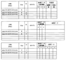
図5に本実施形態で収集される収集データのデータ特性を示す。この図に示すように、本実施形態の収集データには、フロント作業装置6及び上部旋回体3の姿勢データ、油圧ショベル100の位置データ、カメラ62によって撮影された油圧ショベル100の周囲のカメラ画像データ、レーザレーダ61によって取得された油圧ショベル100の周囲の障害物の点群データ、フロント作業装置6によって掘削された土量データ、レーザレーダ61によって取得された現況地形データが含まれる。
(Characteristics of collected data)
Data characteristics of the data collected in this embodiment are shown in Fig. 5. As shown in this figure, the data collected in this embodiment includes attitude data of the front working implement 6 and the upper
図5に示したデータのうち、姿勢データ、位置データ、カメラ画像データ、及び点群データのデータ取得要求カテゴリは第2カテゴリに分類され、土量データと現況地形データの同カテゴリは第1カテゴリに分類される。図5の場合、カテゴリ分類とリアルタイム処理への利用の有無は一致している。すなわち、姿勢データ、位置データ、カメラ画像データ、及び点群データは、リアルタイム処理への利用があり、土量データ及び現況地形データはリアルタイム処理への利用がない。 Of the data shown in Figure 5, the data acquisition request categories of attitude data, position data, camera image data, and point cloud data are classified into the second category, while the same categories of soil volume data and current topography data are classified into the first category. In the case of Figure 5, the category classification matches the presence or absence of use for real-time processing. In other words, attitude data, position data, camera image data, and point cloud data are used for real-time processing, while soil volume data and current topography data are not used for real-time processing.
また図5の例では、各収集データの収集頻度(サーバ201へのアップロード間隔やアップロード周期、油圧ショベル100でのサンプリング周期などとも換言できる)に応じてデータ特性グループをA-Eの5つに分類している。具体的には、収集頻度が10ms以下である姿勢データと位置データはグループAに分類され、収集頻度が10msより大きく50ms以下であるカメラ画像データはグループBに分類され、収集頻度が50msより大きく100ms以下である点群データはグループCに分類され、収集頻度が100msを超える現況地形データはグループDに分類され、収集頻度が設定されていない土量データ(例えば、土量データは旋回ブーム上げ動作の都度計測され得る)はグループEに分類されている。グループの分類は車載コントローラ110側で行っても良いし、サーバ201側で行っても良い。
In the example of FIG. 5, data characteristic groups are classified into five groups, A to E, according to the collection frequency of each collected data (which can also be expressed as the upload interval or upload cycle to the
図6はDB202における収集データの管理方式の一例を示す図である。この図の例ではデータ特性グループ(Grp)ごとにテーブルを分類しており、所属グループ(Grp)とIDの組み合わせからデータの特定が可能である。収集データ分類部240によって収集データがカテゴリ分類された場合には、該当する収集データにカテゴリが付与される。各収集データにはデータを取得したときの油圧ショベル100の位置データと収集時刻(サンプリング時刻)がリンクされている。また、DB202で保存される収集データは、KeyとValueを組み合わせた単純な構造からなるデータストアタイプである。そのため、例えば、複数データベースにデータを分散させて格納する分散データストアとしての利用することで、アクセス性能を向上することができる。
Figure 6 is a diagram showing an example of a method for managing collected data in DB202. In this example, tables are classified by data characteristic group (Grp), and data can be identified from a combination of the group (Grp) to which the data belongs and an ID. When collected data is classified by category by the collected
図4の説明に戻る。ステップS103では、収集データ分類部240による収集データのカテゴリ分類処理と、サーバ負荷管理部232によるサーバ負荷管理処理との制御周期が到来したか否かをチェックする。制御周期が到来した場合にはステップS104に進み、そうでない場合にはステップS101に戻る。なお、このフローではカテゴリ分類処理とサーバ負荷管理処理を同じ周期で行うことにしたが、両者は異なる周期で行っても構わない。
Returning to the explanation of FIG. 4, in step S103, a check is made as to whether or not the control period for the category classification process of the collected data by the collected
ステップS104では、サーバ201(サーバ負荷管理部232)は、サーバ201に搭載された演算処理装置(例えばCPU)の使用率が所定の負荷閾値を超えるか否かを判定する。当該使用率が負荷閾値を超えたと判定されたときは、サーバが高負荷状態にあると判定して高負荷フラグを出力してステップS105に進む。反対に、当該使用率が負荷閾値以下であると判定されたときは、サーバ201は通常負荷状態にある(即ち高負荷状態にない)と判定してステップS101に戻る。
In step S104, the server 201 (server load management unit 232) determines whether the utilization rate of the arithmetic processing unit (e.g., CPU) mounted on the
(カテゴリ分類処理1(図7))
ステップS105では、サーバ201(収集データ分類部240)は、サーバ201が高負荷状態にあるときに受信した収集データのデータ特性に基づいて、第1カテゴリ及び第2カテゴリのいずれか1つのカテゴリに当該収集データを分類する。ここで図7を用いて収集データ分類部240によるカテゴリ分類処理の詳細について説明する。図7はステップS104において収集データ分類部240が行うカテゴリ分類処理のフローチャートの一例を示す図である。
(Category Classification Process 1 (FIG. 7))
In step S105, the server 201 (collected data classification unit 240) classifies the collected data received when the
サーバ201(収集データ分類部240)は、ステップS104に到達すると(即ちサーバ負荷管理部232から高負荷フラグが出力されると)図7の処理を開始する。まず、ステップS201において、サーバ201が高負荷状態にあるときに受信したDB202内の複数の収集データの中から収集データを1つ選択し、その選択した収集データの収集頻度(サンプリング周期)が100ms以下か否かを判定する。選択した収集データの収集頻度が100ms以下の場合にはステップS203に進み、その収集データを第2カテゴリに分類する。一方、収集頻度が100msを超える場合にはステップS205に進み、その収集データを第1カテゴリに分類する。
When the server 201 (collected data classification unit 240) reaches step S104 (i.e., when a high load flag is output from the server load management unit 232), it starts the process of FIG. 7. First, in step S201, one piece of collected data is selected from the multiple pieces of collected data in
ステップ207では、サーバ201(収集データ分類部240)は、サーバ201が高負荷状態にあるときに受信した収集データの全てに対してカテゴリ分類が完了したか否かを判定し、未分類の収集データがある場合にはS201に戻り、サーバ201が高負荷状態にあるときに受信した全ての収集データの分類が完了した場合には図7の処理(ステップS105の処理(カテゴリ分類処理))を終了して図4のステップS106に進む。
In step 207, the server 201 (collected data classification unit 240) determines whether or not category classification has been completed for all collected data received when the
ステップS106では、サーバ201(アップロード時刻変更指令演算部242)は、ステップS105でカテゴリ分類された複数の収集データから1つの収集データを選択し、選択した収集データのカテゴリが第1カテゴリ(間引き要求)か否かを判定する。当該収集データのカテゴリが第1カテゴリの場合はステップS107に進み、第2カテゴリ(即時要求)である場合にはステップS108に進む。 In step S106, the server 201 (upload time change command calculation unit 242) selects one piece of collected data from the multiple pieces of collected data categorized in step S105, and determines whether the category of the selected collected data is the first category (thinning request). If the category of the collected data is the first category, the process proceeds to step S107, and if the category is the second category (immediate request), the process proceeds to step S108.
ステップS107では、サーバ201(アップロード時刻変更指令演算部242)は、ステップS106で選択された第1カテゴリに属する収集データのアップロード間隔(収集頻度)を、その時設定されている第1アップロード間隔(第1時間)から、当該第1アップロード間隔よりも長い第2アップロード間隔(第2時間)に変更する指令(すなわち、選択された収集データのアップロード間隔を新たな値(補正値)に書き換える指令)を演算し、その指令を選択された収集データを送信した車載コントローラ110に出力する。
In step S107, the server 201 (upload time change command calculation unit 242) calculates a command to change the upload interval (collection frequency) of the collected data belonging to the first category selected in step S106 from the first upload interval (first time) set at that time to a second upload interval (second time) that is longer than the first upload interval (i.e., a command to rewrite the upload interval of the selected collected data to a new value (correction value)), and outputs the command to the in-
アップロード時刻変更指令演算部242による変更後のアップロード間隔は、変更前(現在)のアップロード間隔に1より大きい係数を乗ずれば演算できる。例えば、ステップS106で第1カテゴリに属する現況地形データが選択され、現況地形データのアップロード間隔を長くする場合には、次の式(1)によって補正後の現況地形データのアップロード間隔t(I)’を演算できる。
The upload interval after the change made by the upload time change
補正後の現況地形のアップロード間隔(収集周期)t(I)’=補正前の現況地形のアップロード間隔t(I)×(1+(位置データのアップロード間隔t(P))/(位置データのアップロード間隔t(P)+補正前の現況地形のアップロード間隔t(I)) …式(1)
ここで、補正前の現況地形データのアップロード間隔t(I)=1[s]=1000[msec]、位置データのアップロード間隔=10[msec]、とすると、t(I)’=1000×(1+10/(10+1000))=1009.9[msec]となる。すなわち、補正後の現況地形のアップロード間隔t(I)’は補正前よりも9.9[msec]増加する。このときの効果について図8を用いて説明する。
Corrected current terrain upload interval (collection cycle) t(I)'=pre-corrected current terrain upload interval t(I)×(1+(position data upload interval t(P))/(position data upload interval t(P)+pre-corrected current terrain upload interval t(I)) ...Equation (1)
Here, assuming that the upload interval of the current topography data before correction, t(I) = 1 [s] = 1000 [msec], and the upload interval of the position data = 10 [msec], then t(I)' = 1000 x (1 + 10/(10 + 1000)) = 1009.9 [msec]. In other words, the upload interval of the current topography after correction, t(I)', increases by 9.9 [msec] compared to before correction. The effect of this will be explained using FIG. 8.
図8の上の図は或る時刻(便宜上、10[msec]と示す)に姿勢データ、位置データ、カメラ画像データ、点群データ、土量データ、現況地形データが集中した場合(すなわち、アップロード時刻変更指令演算部242によるアップロード間隔の補正前の状況)を示している。この場合、アップロード時刻変更指令演算部242により上記の例のように現況地形データのアップロード間隔を補正すると、現況地形データのアップロード時刻は図8の下の図に示すように10[msec]よりも9.9[msec]遅れるので、10[msec]でのデータ集中を緩和することができサーバ負荷を減少できる。サーバ負荷の減少により、サーバ201が収集データを受信した時点から生成データの特性に合わせて遅滞なく演算処理を完了できるようになる。
The upper diagram in Figure 8 shows a case where attitude data, position data, camera image data, point cloud data, soil volume data, and current terrain data are concentrated at a certain time (shown as 10 [msec] for convenience) (i.e., the situation before the upload interval is corrected by the upload time change command calculation unit 242). In this case, if the upload interval of the current terrain data is corrected by the upload time change
ステップS107が終了したら、サーバ201(アップロード時刻変更指令演算部242)は、ステップS105でカテゴリ分類された全ての収集データについてステップS106の判定を行ったか否かを判定する。全ての収集データについてステップS106の判定を行った場合には、ステップS101に戻り、そうで無い場合にはステップS106に戻る。 When step S107 is completed, the server 201 (upload time change command calculation unit 242) determines whether or not the determination in step S106 has been performed for all collected data categorized in step S105. If the determination in step S106 has been performed for all collected data, the process returns to step S101; otherwise, the process returns to step S106.
(生成データの演算例)
図9に本実施形態のサーバ201が実行する生成データの演算処理の一例として、油圧ショベル100が障害物に接近した場合に走行禁止指令(生成データ)を演算する処理のフローチャートを示す。なお、ここでは、サーバ201の管理下にある複数の油圧ショベル100のうち、特定の油圧ショベル100(車載コントローラ110)からの収集データを受信して、当該特定の油圧ショベル100に生成データ(走行禁止指令)を送信する場合を想定している。
(Example of calculation of generated data)
9 shows a flowchart of a process for calculating a travel prohibition command (generated data) when the
ステップS501では、サーバ201は、制御対象の油圧ショベル100(車載コントローラ110)から位置データを受信(取得)する。
In step S501, the
ステップS502では、サーバ201は、今回ステップS501で受信した位置データと、今回よりも前(例えば、1周期前のステップS501)に受信した位置データとを比較して、制御対象の油圧ショベル(第1作業機械)100が走行したか否かを判定する。ここで受信した位置データに変化があった場合には制御対象の油圧ショベル100は走行したと判定してステップS503に進む。反対に、位置データに変化がない場合には制御対象の油圧ショベル100は停止していると判定してステップS501に戻る。
In step S502, the
ステップS503では、サーバ201は、制御対象の油圧ショベル100から姿勢データを取得し、取得した姿勢データとステップS501で取得した位置データとに基づいて、制御対象の油圧ショベル100のフロント作業装置6の位置を演算する。
In step S503, the
ステップS504では、サーバ201は、制御対象の油圧ショベル100からカメラ画像データを取得して、そのカメラ画像に写った障害物を検出し、カメラ62から当該障害物までの距離を演算する。カメラ画像がステレオカメラ画像(視差画像)であればカメラ62から当該障害物までの距離は容易に演算できる。
In step S504, the
ステップS505では、サーバ201は、ステップS503で演算したフロント作業装置6の位置と、ステップS504で演算した障害物までの距離(障害物の位置)とに基づいて、フロント作業装置6から障害物までの距離Lを演算する。
In step S505, the
ステップS506では、サーバ201は、ステップS506で演算した距離Lが所定の距離閾値L1未満か否かを判定する。距離Lが閾値L1未満の場合には、カメラ62で検出した障害物と接触する可能性があると判定して制御対象の油圧ショベル100に対して、走行を停止又はオペレータから入力される走行操作を無効にする、走行禁止指令を出力する。これにより例え制御対象の油圧ショベル100が走行中でも、その走行動作が停止されて障害物との接触を防止することができる。
In step S506, the
ステップS506で距離Lが閾値L1以上の場合には、サーバ201は一旦処理を終了し、次の制御周期まで待機する。
If the distance L is equal to or greater than the threshold L1 in step S506, the
(作用・効果)
図9のフローで使用されるデータは、グループAに属する位置データ及び姿勢データ(図5参照)と、グループBに属するカメラ画像データ(図5参照)である。そのため、これら3種のデータがサーバ201に受信されるタイミングでサーバ201の負荷が高いと、走行禁止指令の生成に要する時間が増大し、走行禁止指令の基となる3種のデータが制御対象の油圧ショベル100でサンプリング(収集)された時刻と、サーバ201で生成された走行禁止指令が当該制御対象の油圧ショベル100に受信される時刻とのギャップが増大する虞がある。両時刻のギャップの増大は油圧ショベル100の制御精度の低下を意味し、油圧ショベル100が障害物に衝突する虞が高まる。
(Action and Effects)
The data used in the flow of Fig. 9 are the position data and attitude data belonging to group A (see Fig. 5) and the camera image data belonging to group B (see Fig. 5). Therefore, if the load on the
そこで本実施形態では、図4に示したフローを利用することで、サーバへのデータ送信が集中してサーバが高負荷状態になる場合には、リアルタイム処理に利用されるデータの受信を優先する一方で、リアルタイム処理に利用しないデータの受信を遅らせることとした。これにより、サーバ201が、上記3種のデータをほぼ同時刻に受信でき、さらに遅滞なく図9に示したフローを実行することができるので、上記の3種のデータが油圧ショベル100でサンプリングされた時刻と、走行禁止指令が当該油圧ショベル100で受信される時刻との間に大きなギャップが生じることが防止でき、油圧ショベル100を精度良く制御でき障害物との衝突を防止できる。
In this embodiment, by using the flow shown in FIG. 4, when data transmission to the server is concentrated and the server becomes highly loaded, the reception of data used for real-time processing is prioritized, while the reception of data not used for real-time processing is delayed. This allows the
(補足)
なお、上記の図4のフローでは、サーバ201が高負荷状態にあるときに収集データのカテゴリ分類処理(ステップS105)を実行したが、サーバ201が通常負荷の場合にカテゴリ分類処理を行っておいても構わない。すなわち、例えば、ステップS102とS103の間や、ステップS103とS104の間などでカテゴリ分類処理を行っても良い。また、高負荷状態のときに受信した全ての収集データについてステップS105の処理を行った後にステップS106に遷移したが、高負荷状態のときに受信した収集データのそれぞれについてステップS105及びS106,さらにはステップS107の処理を行っても良い。なお、これらは以降に説明する変形例や他の実施形態でも同様である。
(supplement)
In the flow of Fig. 4, the collected data is classified into categories (step S105) when the
また、収集データ分類部240による収集データのカテゴリ分類処理は、上記の図7に示した方法に限らず他の方法も利用可能である。次に他のカテゴリ分類処理について説明する。
The category classification process of the collected data by the collected
(カテゴリ分類処理2(図10))
図10は、図4のステップS104において収集データ分類部240が行うカテゴリ分類処理のフローチャートの他の例を示す図である。なお、図7と同じ処理は同じ符号を付して説明を省略することがある(これ以降に説明する図についても同様に扱う)。
(Category Classification Process 2 (FIG. 10))
Fig. 10 is a diagram showing another example of a flowchart of the category classification process performed by the collected
サーバ201(収集データ分類部240)は、ステップS104に到達すると(即ちサーバ負荷管理部232から高負荷フラグが出力されると)図10の処理を開始する。 When the server 201 (collected data classification unit 240) reaches step S104 (i.e., when a high load flag is output from the server load management unit 232), it starts the process of FIG. 10.
まず、ステップS220において、サーバ負荷管理部232によってサーバ201が高負荷状態にあると判定された回数である高負荷回数nを1カウントアップする。なお、図4のフローの開始時の高負荷回数nの値(初期値)はゼロであり、図4のフローの終了時に高負荷回数nをゼロリセットする。すなわち、高負荷回数nは図4のフローが開始されてからサーバ負荷管理部232によってサーバ201が高負荷状態にあると判定された回数(すなわち高負荷フラグが出力された回数)である。
First, in step S220, the high load count n, which is the number of times that the server
ステップS222では、サーバ201(収集データ分類部240)は、サーバ201が高負荷状態にあるときに受信したDB202内の複数の収集データの中から収集データを1つ選択し、その選択した収集データがサーバ201が高負荷状態にあるときに受信した複数の収集データの中でm番目までに収集頻度(サンプリング間隔)が長いデータか否かを判定する。ただし、m=n+c1であり、c1はゼロ以上の整数とする。
In step S222, the server 201 (collected data classification unit 240) selects one piece of collected data from among the multiple pieces of collected data in the
ここでは説明を簡単にするためにc1=0とする。この場合、n=1のときにm=1となり、ステップS222では、サーバ201(収集データ分類部240)は、選択した収集データが、サーバ高負荷状態のときに受信した収集データの中で最も収集頻度が長いデータか否かを判定する。そして、選択した収集データが最も収集頻度の長いデータの場合にはその収集データを第1カテゴリに分類し(ステップS205)、そうでない場合にはその収集データを第2カテゴリに分類する(ステップS203)。すなわち、これらの処理により、m番目に収集頻度が長い収集データまでが第1カテゴリに分類され、残りの収集データ(m+1番目以降に収集頻度が長い収集データ)は第2カテゴリに分類される。 For simplicity, let c1 = 0 here. In this case, when n = 1, m = 1, and in step S222, the server 201 (collected data classification unit 240) determines whether the selected collected data is the most frequently collected data among the collected data received when the server was in a high load state. If the selected collected data is the most frequently collected data, it is classified into the first category (step S205), and if not, it is classified into the second category (step S203). That is, through these processes, the collected data up to the mth most frequently collected data are classified into the first category, and the remaining collected data (collected data with the most frequently collected data after m+1) are classified into the second category.
このように図10のフローでは、サーバ201(収集データ分類部240)は、DB202に取り込まれた収集データのうち複数の車載コントローラ110における収集頻度(収集周期)が相対的に長い収集データを第1カテゴリに分類し、収集頻度(収集周期)が相対的に短い収集データを第2カテゴリに分類する収集データのカテゴリを分類することとした。このように収集データのカテゴリを分類しても先に説明した効果と同様の効果が発揮できる。
In this manner, in the flow of FIG. 10, the server 201 (collected data classification unit 240) classifies the collected data into the
ただし、図10の例では、サーバ201が高負荷状態にあると判定された回数の増加に応じて、第1カテゴリに分類される収集データの数が自動的に増加されるため、施工管理者が第1カテゴリに分類する収集データの数を積極的に設定しなくても、サーバ負荷が通常状態で維持される方向にシステムを遷移させることができる点が特徴的なメリットとなる。
However, in the example of FIG. 10, the number of collected data items classified into the first category is automatically increased in accordance with an increase in the number of times that
(カテゴリ分類処理3(図11))
図11は、図4のステップS104において収集データ分類部240が行うカテゴリ分類処理のフローチャートの他の例を示す図である。
(Category Classification Process 3 (FIG. 11))
FIG. 11 is a diagram showing another example of a flowchart of the category classification process performed by the collected
ステップS210において、サーバ201(収集データ分類部240)は、サーバ201が高負荷状態にあるときに受信したDB202内の複数の収集データの中から収集データを1つ選択し、その選択した収集データがリアルタイム処理に利用されるか否かを判定する。選択した収集データがリアルタイム処理に利用される場合にはステップS203に進み、その収集データを第2カテゴリに分類する。一方、リアルタイム処理に利用されない場合にはステップS205に進み、その収集データを第1カテゴリに分類する。各収集データがリアルタイム処理に利用されるか否かは図5の表の「性質」に示している。リアルタイム処理には、図9に示した走行禁止指令を演算する障害物衝突防止処理が含まれる。なお、姿勢データ、位置データ、点群データを利用して障害物衝突防止処理を行っても良い。
In step S210, the server 201 (collected data classification unit 240) selects one piece of collected data from the multiple pieces of collected data in the
このように図11のフローでは、サーバ201(収集データ分類部240)は、DB202に取り込まれた収集データのうち、サーバ201によるリアルタイム処理に利用されない収集データを第1カテゴリに分類し、サーバ201によるリアルタイム処理に利用される収集データを第2カテゴリに分類することとした。このように収集データのカテゴリを分類しても図7の処理を行った場合と同様の効果が発揮できる。
In this manner, in the flow of FIG. 11, the server 201 (collected data classification unit 240) classifies, among the collected data imported into the
(カテゴリ分類処理4(図12))
図12は、図4のステップS104において収集データ分類部240が行うカテゴリ分類処理のフローチャートの他の例を示す図である。
(Category Classification Process 4 (FIG. 12))
FIG. 12 is a diagram showing another example of a flowchart of the category classification process performed by the collected
ステップS212において、サーバ201(収集データ分類部240)は、サーバ201が高負荷状態にあるときに受信したDB202内の複数の収集データの中から収集データを1つ選択し、その選択した収集データとサーバ201で同時処理される収集データが存在するか否かを判定する。選択した収集データと同時処理される収集データが存在する場合にはステップS214に進み、選択した収集データと、その選択した収集データと同時処理される収集データとを第2カテゴリに分類する。一方、同時処理される収集データが存在しない場合にはステップS205に進み、選択した収集データを第1カテゴリに分類する。同時処理される収集データとしては、図9の例に示した姿勢データ、位置データ、カメラ画像データがある。また、姿勢データ、位置データ、点群データを利用して障害物衝突防止処理を行った場合にはこれらも同時処理される収集データとなる。
In step S212, the server 201 (collected data classification unit 240) selects one piece of collected data from among the multiple pieces of collected data in the
このように図12のフローでは、サーバ201(収集データ分類部240)は、DB202に取り込まれた収集データのうち、サーバ201による生成データの生成に際して同時に利用される収集データが存在しない収集データを第1カテゴリに分類し、サーバ201による生成データの生成に際して同時に利用される収集データが存在する収集データを第2カテゴリに分類することとした。このように収集データのカテゴリを分類しても図7の処理を行った場合と同様の効果が発揮できる。
In this manner, in the flow of FIG. 12, the server 201 (collected data classification unit 240) classifies collected data that is imported into the
(サーバ201のフローチャート2(図13))
ところで、上記では、図4に示すように第1カテゴリに分類された収集データのアップロード間隔(収集頻度)を長くする処理を行ったが、それとともに第2カテゴリに分類された収集データのアップロード間隔を短くする処理を行っても良い。次に、その場合にサーバ201で行われる処理について図13を用いて説明する。
(
In the above, the upload interval (collection frequency) of collected data classified into the first category is lengthened as shown in Fig. 4, but at the same time, the upload interval of collected data classified into the second category may be shortened. Next, the process performed by the
図13は本実施形態のサーバ201で実行される処理の他の例をフローチャートで示した図である。この図のフローチャートでは、サーバ高負荷時、第1カテゴリの収集データについてはアップロード間隔を増加する補正処理を行い、第2カテゴリの収集データについてはアップロード間隔を低減する補正処理を行う。なお、図4のフローとの違いはステップS109だけである。ここではステップS109の処理のみを説明し、他の処理については説明を省略する。
Figure 13 is a flowchart showing another example of the processing executed by the
ステップS109では、サーバ201(アップロード時刻変更指令演算部242)は、ステップS106で選択された第2カテゴリに属する収集データのアップロード間隔(収集頻度)を、その時設定されている第3アップロード間隔(第3時間)から、当該第3アップロード間隔よりも短い第4アップロード間隔(第4時間)に変更する指令(すなわち、選択された収集データのアップロード間隔を新たな値(補正値)に書き換える指令)を演算し、その指令を選択された収集データを送信した車載コントローラ110に出力する。
In step S109, the server 201 (upload time change command calculation unit 242) calculates a command to change the upload interval (collection frequency) of the collected data belonging to the second category selected in step S106 from the currently set third upload interval (third hour) to a fourth upload interval (fourth hour) that is shorter than the third upload interval (i.e., a command to rewrite the upload interval of the selected collected data to a new value (correction value)), and outputs the command to the in-
アップロード時刻変更指令演算部242による変更後のアップロード間隔は、変更前(現在)のアップロード間隔に1より小さい係数を乗ずれば演算できる。例えば、ステップS106で第2カテゴリに属するカメラ画像データが選択され、カメラ画像データのアップロード間隔を短くする場合には、次の式(2)によって補正後のカメラ画像データのアップロード間隔t(C)’を演算できる。
The upload interval after the change made by the upload time change
補正後のカメラ画像データのアップロード間隔(収集周期)t(C)’=補正前のカメラ画像データのアップロード間隔t(C)×(1-(位置データのアップロード間隔t(P)/補正前のカメラ画像データのアップロード間隔t(C)) …式(2)
ここで、補正前のカメラ画像データのアップロード間隔t(C)=33[msec]、位置データのアップロード間隔=10[msec]、とすると、t(C)’=33×(1+(10/33))=23[msec]となる。すなわち、補正後のカメラ画像データのアップロード間隔t(C)’は補正前よりも10[msec]低減する。このときの効果を図14に示す。
Corrected camera image data upload interval (collection cycle) t(C)′=uncorrected camera image data upload interval t(C)×(1−(position data upload interval t(P)/uncorrected camera image data upload interval t(C)) …Equation (2)
Here, assuming that the upload interval of camera image data before correction, t(C)=33 [msec] and the upload interval of location data=10 [msec], then t(C)'=33×(1+(10/33))=23 [msec]. In other words, the upload interval of camera image data after correction, t(C)', is reduced by 10 [msec] compared to before correction. The effect of this is shown in FIG. 14.
図14の上の図は或る時刻(便宜上、10[msec]と示す)に姿勢データ、位置データ、カメラ画像データ、点群データ、土量データ、現況地形データが集中した場合(すなわち、アップロード時刻変更指令演算部242によるアップロード間隔の補正前の状況)を示している。この場合、アップロード時刻変更指令演算部242により上記の例のようにカメラ画像データのアップロード間隔を補正して、その補正後のアップロード間隔に準じた時刻に取得したカメラ画像データをサーバ201にアップロードさせる指令(アップロード指令(データ要求))を該当する車載コントローラ110に出力する。このアップロード指令により、カメラ画像データのアップロード時刻は図14の下の図に示すように補正前よりも10[msec]早くなり、グループAの姿勢データ及び位置データと同時に利用できる時刻も10[msec]早まるので、例えば所定時間内に障害物衝突防止処理を実行できる回数を補正前よりも向上できる。図14では、障害物衝突防止処理に必要な3種のデータ(グループAの姿勢データ及び位置データと、グループBのカメラ画像データ)が同時に取得できるタイミングを、グループ名を四角で囲うことで示しているが、補正前では60[msec]につき2回であったが、補正後では3回に増加している。
The upper diagram of FIG. 14 shows a case where attitude data, position data, camera image data, point cloud data, soil volume data, and current topography data are concentrated at a certain time (shown as 10 [msec] for convenience) (i.e., the situation before the upload interval is corrected by the upload time change command calculation unit 242). In this case, the upload time change
このように図13に示すように第2カテゴリに分類された収集データのアップロード間隔を短くすると、同時処理されるべき複数の収集データを同じタイミングで受信できるようになるので、サーバ201のリアルタイム処理による油圧ショベル100の制御精度を向上できる。
As shown in FIG. 13, by shortening the upload interval of collected data classified into the second category in this way, multiple pieces of collected data that should be processed simultaneously can be received at the same time, thereby improving the control accuracy of the
なお、図14の例では、同時処理される複数の収集データのうち、アップロード間隔が長い方(グループB)のアップロード間隔を短い方(グループA)に合わせて補正したが、アップロード間隔が短い方(グループA)のアップロード間隔を長い方(グループB)に合わせて補正しても良い。また、図14の例では、サーバ201からアップロード指令を出力することで車載コントローラ110から所望のタイミングで所望の収集データを受信する仕組みを採用したが、先に説明した例のように対象の収集データのアップロード間隔を補正後の値に変更する指令をサーバ201から対象の車載コントローラ110に出力する仕組みを採用しても良い。
In the example of FIG. 14, the upload interval of the group with the longer upload interval (group B) among the multiple collected data processed simultaneously is corrected to match the group with the shorter upload interval (group A), but the upload interval of the group with the shorter upload interval (group A) may also be corrected to match the group with the longer upload interval (group B). Also, in the example of FIG. 14, a mechanism is adopted in which the
(複数の作業機械からの収集データの受信)
図15は複数の油圧ショベル100(作業機械)から収集データを受信する場合のタイミングチャートである。上記では説明を簡略化するために1台の油圧ショベル100(作業機械)の収集データを受信する場合を例示したが、実際の現場では図15に示すようにサーバ201の管理下にある複数の油圧ショベル100から多くのデータが送信される。したがって、本実施形態のように各収集データのデータ特性に合わせて受信時刻(車載コントローラ110からのアップロード間隔)を変更する処理を実施してデータ集中によるサーバ負荷の増加を防止することは非常に有益な対応であるといえる。
(Receiving collected data from multiple work machines)
Fig. 15 is a timing chart for receiving collected data from a plurality of hydraulic excavators 100 (work machines). In the above, in order to simplify the explanation, an example has been given of a case in which collected data from one hydraulic excavator 100 (work machine) is received, but in an actual work site, a large amount of data is transmitted from a plurality of
また、複数の作業機械からの収集データは、作業効率、作業進捗等の状況を判断するため、収集された時間通りにサーバ201が収集データを受信できるのが望ましい。しかし、複数の作業機械からデータ収集を行うと、サーバ負荷の増大によって収集データの受信にタイムラグが発生する可能性がある。受信タイムラグの発生が継続すると、収集データの一貫性がなくなるため、複数の作業機械からの収集データの統合管理を行う上で、収集データの時間管理に問題が発生する。しかし、本実施形態のように各収集データのデータ特性に合わせて受信時刻(車載コントローラ110からのアップロード間隔)を変更すれば、データ集中によるサーバ負荷の増大を防止できるので受信タイムラグの発生も防止できる。
In addition, in order to determine the status of work efficiency, work progress, and the like, it is desirable for the
(その他)
なお、本発明は、上記の実施の形態に限定されるものではなく、その要旨を逸脱しない範囲内の様々な変形例が含まれる。例えば、本発明は、上記の実施の形態で説明した全ての構成を備えるものに限定されず、その構成の一部を削除したものも含まれる。また、ある実施の形態に係る構成の一部を、他の実施の形態に係る構成に追加又は置換することが可能である。
(others)
The present invention is not limited to the above-described embodiments, and includes various modifications within the scope of the gist of the present invention. For example, the present invention is not limited to those having all the configurations described in the above-described embodiments, and includes those in which some of the configurations are deleted. Also, it is possible to add or replace some of the configurations of one embodiment with the configurations of another embodiment.
また、上記のコントローラ110,サーバ201に係る各構成や当該各構成の機能及び実行処理等は、それらの一部又は全部をハードウェア(例えば各機能を実行するロジックを集積回路で設計する等)で実現しても良い。また、上記のコントローラ110,サーバ201に係る構成は、演算処理装置(例えばCPU)によって読み出し・実行されることでコントローラ110,サーバ201の構成に係る各機能が実現されるプログラム(ソフトウェア)としてもよい。当該プログラムに係る情報は、例えば、半導体メモリ(フラッシュメモリ、SSD等)、磁気記憶装置(ハードディスクドライブ等)及び記録媒体(磁気ディスク、光ディスク等)等に記憶することができる。
The configurations of the
また、上記の各実施の形態の説明では、制御線や情報線は、当該実施の形態の説明に必要であると解されるものを示したが、必ずしも製品に係る全ての制御線や情報線を示しているとは限らない。実際には殆ど全ての構成が相互に接続されていると考えて良い。 In addition, in the above explanation of each embodiment, the control lines and information lines are those that are considered necessary for the explanation of the embodiment, but they do not necessarily show all the control lines and information lines related to the product. In reality, it can be considered that almost all components are connected to each other.
2…走行体(下部走行体),3…旋回体(上部旋回体),6…フロント作業装置,6A…ブーム,6B…アーム,6C…バケット,7…無線通信装置,11A…ブームシリンダ,11B…アームシリンダ,11C…バケットシリンダ,23…旋回体姿勢センサ,40…車載コントローラ,50A…GNSSアンテナ,50B…GNSSアンテナ,51…GNSS受信機(位置センサ),61…レーザレーダ(LIDAR),62…カメラ,63a…ブームロッド圧センサ,63b…ブームボトム圧センサ,75A…ブーム姿勢センサ,75B…アーム姿勢センサ,75C…バケット姿勢センサ,100…油圧ショベル(作業機械),110…車載コントローラ,110…コントローラ,200…施工履歴情報管理システム,201…サーバ,202…データベース(DB),203…モニタ,204…入力装置,211…通信装置,220…データ入力部,222…データ出力部,230…記憶部,232…サーバ負荷管理部,234…データ生成部,240…収集データ分類部,242…アップロード時刻変更指令演算部 2...Traveling body (lower traveling body), 3...Rotating body (upper rotating body), 6...Front working device, 6A...Boom, 6B...Arm, 6C...Bucket, 7...Wireless communication device, 11A...Boom cylinder, 11B...Arm cylinder, 11C...Bucket cylinder, 23...Rotating body attitude sensor, 40...On-board controller, 50A...GNSS antenna, 50B...GNSS antenna, 51...GNSS receiver (position sensor), 61...Laser radar (LIDAR), 62...Camera, 63a...Boom rod pressure sensor, 63b...Boom bottom pressure sensor, 75A ...Boom position sensor, 75B...Arm position sensor, 75C...Bucket position sensor, 100...Hydraulic excavator (work machine), 110...On-board controller, 110...Controller, 200...Construction history information management system, 201...Server, 202...Database (DB), 203...Monitor, 204...Input device, 211...Communication device, 220...Data input unit, 222...Data output unit, 230...Storage unit, 232...Server load management unit, 234...Data generation unit, 240...Collected data classification unit, 242...Upload time change command calculation unit
Claims (7)
前記サーバは、
前記データベースに取り込まれた収集データをそのデータ特性に基づいて、第1カテゴリ及び前記第1カテゴリよりも前記サーバでの利用の優先度の高い第2カテゴリを含む複数のカテゴリのいずれかのカテゴリに分類し、
前記サーバの負荷を示す負荷指標値が所定の負荷閾値を超えたとき、前記第1カテゴリに分類された収集データ及び前記第2カテゴリに分類された収集データのうち前記第1カテゴリに分類された収集データに対してのみアップロード間隔をより長い時間に変更する指令を、前記複数の車載コントローラのうち前記第1カテゴリに分類された収集データを送信した車載コントローラに出力し、前記第1カテゴリに分類された収集データ及び前記第2カテゴリに分類された収集データを収集する
ことを特徴とする施工履歴情報管理システム。 A construction history information management system including a server having a communication device that communicates with a plurality of on-board controllers mounted on a plurality of work machines and receives collected data transmitted from the plurality of on-board controllers, and a database into which the collected data received by the communication device is input ,
The server,
classifying the collected data inputted into the database into any one of a plurality of categories including a first category and a second category having a higher priority for use in the server than the first category based on the data characteristics;
When a load index value indicating a load on the server exceeds a predetermined load threshold, a command to change an upload interval to a longer time only for the collected data classified into the first category among the collected data classified into the first category and the collected data classified into the second category is output to an in-vehicle controller, among the multiple in-vehicle controllers , that has transmitted the collected data classified into the first category, and the collected data classified into the first category and the collected data classified into the second category are collected.
A construction history information management system characterized by the above.
前記サーバは、
前記データベースに取り込まれた収集データをそのデータ特性に基づいて、第1カテゴリ及び第2カテゴリを含む複数のカテゴリのいずれかのカテゴリに分類し、
前記サーバの負荷を示す負荷指標値が所定の負荷閾値を超えたとき、前記第1カテゴリに分類された収集データのアップロード間隔をより長い時間に変更する指令を、前記複数の車載コントローラのうち前記第1カテゴリに分類された収集データを送信した車載コントローラに出力し、
前記負荷指標値が前記所定の負荷閾値を超えたとき、前記第2カテゴリに分類された収集データのアップロード間隔をより短い時間に変更する指令を、前記複数の車載コントローラのうち前記第2カテゴリに分類された収集データを送信した車載コントローラに出力する
ことを特徴とする施工履歴情報管理システム。 A construction history information management system including a communication device that communicates with a plurality of on-board controllers mounted on a plurality of work machines and receives collected data that is data transmitted from the plurality of on-board controllers, a database into which the collected data received by the communication device is input, and a server that generates new data based on the collected data input into the database and transmits the generated data as generated data to the plurality of on-board controllers via the communication device,
The server,
Classifying the collected data entered into the database into any one of a plurality of categories including a first category and a second category based on the data characteristics;
when a load index value indicating a load on the server exceeds a predetermined load threshold, a command to change an upload interval of the collected data classified into the first category to a longer time is output to an in-vehicle controller, among the plurality of in-vehicle controllers, that has transmitted the collected data classified into the first category;
a command to change the upload interval of the collected data classified into the second category to a shorter time when the load index value exceeds the predetermined load threshold is output to an on-board controller among the plurality of on-board controllers that transmitted the collected data classified into the second category.
前記サーバは、前記データベースに取り込まれた収集データのうち前記複数の車載コントローラにおける収集周期が所定の周期閾値より長い収集データを前記第1カテゴリに分類し、前記データベースに取り込まれた収集データのうち前記収集周期が前記周期閾値より短い収集データを前記第2カテゴリに分類する
ことを特徴とする施工履歴情報管理システム。 In the construction history information management system according to claim 2,
the server classifies collected data, among the collected data imported into the database, whose collection period in the multiple on-board controllers is longer than a predetermined period threshold, into the first category, and classifies collected data, among the collected data imported into the database, whose collection period is shorter than the period threshold, into the second category.
前記サーバは、前記データベースに取り込まれた収集データのうち、前記サーバによるリアルタイム処理に利用されない収集データを前記第1カテゴリに分類し、前記サーバによるリアルタイム処理に利用される収集データを前記第2カテゴリに分類する
ことを特徴とする施工履歴情報管理システム。 In the construction history information management system according to claim 2,
The construction history information management system is characterized in that the server classifies collected data that is not used for real-time processing by the server into the first category, and classifies collected data that is used for real-time processing by the server into the second category, among the collected data imported into the database.
前記サーバは、前記データベースに取り込まれた収集データのうち、前記サーバによる前記生成データの生成に際して同時に利用される収集データが存在しない収集データを前記第1カテゴリに分類し、前記サーバによる前記生成データの生成に際して同時に利用される収集データが存在する収集データを前記第2カテゴリに分類する
ことを特徴とする施工履歴情報管理システム。 In the construction history information management system according to claim 2,
The construction history information management system is characterized in that the server classifies collected data imported into the database into the first category for which no collected data exists that is used simultaneously when the server generates the generated data, and classifies collected data into the second category for which collected data exists that is used simultaneously when the server generates the generated data.
前記サーバによって前記第2カテゴリに分類される収集データには、前記複数の作業機械の姿勢データ、前記複数の作業機械の位置データ、前記複数の作業機械に搭載されたカメラにより撮影されたカメラ画像データ、及び前記複数の作業機械に搭載された距離センサにより取得された距離センサデータの少なくとも1つが含まれており、
前記サーバによって前記第1カテゴリに分類される収集データには、前記複数の作業機械が運搬した土量データ、及び前記複数の作業機械の周囲の現況地形データのうち少なくとも1つが含まれている
ことを特徴とする施工履歴情報管理システム。 In the construction history information management system according to claim 2,
the collected data classified into the second category by the server includes at least one of attitude data of the plurality of work machines, position data of the plurality of work machines, camera image data captured by a camera mounted on the plurality of work machines, and distance sensor data acquired by a distance sensor mounted on the plurality of work machines;
a construction history information management system, characterized in that the collected data classified into the first category by the server includes at least one of data on the volume of soil transported by the plurality of work machines and data on current topography around the plurality of work machines.
前記サーバは、
第1作業機械に搭載されたカメラにより撮影されたカメラ画像データ、前記第1作業機械に搭載された位置センサにより検出された前記第1作業機械の位置データ、及び前記第1作業機械に搭載された姿勢センサにより検出された前記第1作業機械の姿勢データを前記収集データとして受信して前記第2カテゴリに分類し、
前記位置データに基づいて前記第1作業機械が走行中であると判定した場合、前記カメラ画像データ及び前記姿勢データに基づいて前記第1作業機械から障害物までの距離を演算し、演算した前記距離が所定の距離閾値未満のときに前記第1作業機械を停止させる指令を前記第1作業機械の車載コントローラに出力する
ことを特徴とする施工履歴情報管理システム。 In the construction history information management system according to claim 1 or 2 ,
The server,
camera image data captured by a camera mounted on a first work machine, position data of the first work machine detected by a position sensor mounted on the first work machine, and attitude data of the first work machine detected by an attitude sensor mounted on the first work machine are received as the collected data and classified into the second category;
a control unit for controlling a vehicle that is running a construction history information management system, the control unit for controlling a vehicle that is running a construction history information management system, the control unit for controlling a vehicle that is running a construction history information management system, and the control unit for controlling a vehicle that is running a construction history information management system.
Priority Applications (1)
| Application Number | Priority Date | Filing Date | Title |
|---|---|---|---|
| JP2020048391A JP7470539B2 (en) | 2020-03-18 | 2020-03-18 | Construction history information management system |
Applications Claiming Priority (1)
| Application Number | Priority Date | Filing Date | Title |
|---|---|---|---|
| JP2020048391A JP7470539B2 (en) | 2020-03-18 | 2020-03-18 | Construction history information management system |
Publications (3)
| Publication Number | Publication Date |
|---|---|
| JP2021149475A JP2021149475A (en) | 2021-09-27 |
| JP2021149475A5 JP2021149475A5 (en) | 2023-03-24 |
| JP7470539B2 true JP7470539B2 (en) | 2024-04-18 |
Family
ID=77848907
Family Applications (1)
| Application Number | Title | Priority Date | Filing Date |
|---|---|---|---|
| JP2020048391A Active JP7470539B2 (en) | 2020-03-18 | 2020-03-18 | Construction history information management system |
Country Status (1)
| Country | Link |
|---|---|
| JP (1) | JP7470539B2 (en) |
Citations (6)
| Publication number | Priority date | Publication date | Assignee | Title |
|---|---|---|---|---|
| WO2013161946A1 (en) | 2012-04-27 | 2013-10-31 | 日立建機株式会社 | Operating machine management device |
| JP2016104925A (en) | 2013-03-08 | 2016-06-09 | 日立建機株式会社 | Management system for work machine, client terminal, and server |
| WO2017037784A1 (en) | 2015-08-28 | 2017-03-09 | 日産自動車株式会社 | Probe data collection method and probe data collection device |
| JP2019159727A (en) | 2018-03-12 | 2019-09-19 | 日立建機株式会社 | Construction management system and work machine |
| JP2019190193A (en) | 2018-04-27 | 2019-10-31 | 日立建機株式会社 | Work machine |
| JP2020038362A (en) | 2018-08-31 | 2020-03-12 | 株式会社デンソー | Vehicle-side device, server, method, and storage medium |
-
2020
- 2020-03-18 JP JP2020048391A patent/JP7470539B2/en active Active
Patent Citations (6)
| Publication number | Priority date | Publication date | Assignee | Title |
|---|---|---|---|---|
| WO2013161946A1 (en) | 2012-04-27 | 2013-10-31 | 日立建機株式会社 | Operating machine management device |
| JP2016104925A (en) | 2013-03-08 | 2016-06-09 | 日立建機株式会社 | Management system for work machine, client terminal, and server |
| WO2017037784A1 (en) | 2015-08-28 | 2017-03-09 | 日産自動車株式会社 | Probe data collection method and probe data collection device |
| JP2019159727A (en) | 2018-03-12 | 2019-09-19 | 日立建機株式会社 | Construction management system and work machine |
| JP2019190193A (en) | 2018-04-27 | 2019-10-31 | 日立建機株式会社 | Work machine |
| JP2020038362A (en) | 2018-08-31 | 2020-03-12 | 株式会社デンソー | Vehicle-side device, server, method, and storage medium |
Also Published As
| Publication number | Publication date |
|---|---|
| JP2021149475A (en) | 2021-09-27 |
Similar Documents
| Publication | Publication Date | Title |
|---|---|---|
| US10852139B2 (en) | Positioning method, positioning device, and robot | |
| US10416314B2 (en) | Machine control system and method | |
| KR20210036973A (en) | A recording medium in which an external shape calculation system, an external shape calculation method, an external shape calculation program, and an external shape calculation program are recorded, a packaging map creation system, a packaging map creation program, a recording medium in which a packaging map creation program is recorded, and How to create a pavement map | |
| AU2021201894B2 (en) | Shape measuring system and shape measuring method | |
| KR101815269B1 (en) | Position measuring system and position measuring method | |
| CA2674398C (en) | A vehicle control system | |
| JP6674846B2 (en) | Shape measuring system, work machine and shape measuring method | |
| CN113107043A (en) | Controlling motion of a machine using sensor fusion | |
| JP7203616B2 (en) | working machine | |
| JP7071203B2 (en) | Work machine | |
| CN110779656A (en) | Machine stability detection and control system | |
| JP2021001436A (en) | Work machine | |
| JP7068781B2 (en) | Harvester | |
| US20200369290A1 (en) | System and method for configuring worksite warning zones | |
| CN110578347B (en) | Self-protection system of working machine | |
| JP7470539B2 (en) | Construction history information management system | |
| EP3757299B1 (en) | Apparatus for generating environment data around construction equipment and construction equipment including the same | |
| JP2019162053A (en) | Field registration device | |
| JP2020016147A (en) | Shape measurement system and shape measurement method | |
| JP7082906B2 (en) | Control device and control method | |
| US20230417018A1 (en) | Control device, control system, and control method | |
| JP7166326B2 (en) | Construction management system | |
| US20220333338A1 (en) | Work machine | |
| JP2018112051A (en) | Control system of work machine, work machine, control method of work machine, and navigation controller | |
| WO2022230880A1 (en) | Control method, control system, and control device |
Legal Events
| Date | Code | Title | Description |
|---|---|---|---|
| A521 | Request for written amendment filed |
Free format text: JAPANESE INTERMEDIATE CODE: A523 Effective date: 20230315 |
|
| A621 | Written request for application examination |
Free format text: JAPANESE INTERMEDIATE CODE: A621 Effective date: 20230315 |
|
| A977 | Report on retrieval |
Free format text: JAPANESE INTERMEDIATE CODE: A971007 Effective date: 20231124 |
|
| A131 | Notification of reasons for refusal |
Free format text: JAPANESE INTERMEDIATE CODE: A131 Effective date: 20240109 |
|
| A521 | Request for written amendment filed |
Free format text: JAPANESE INTERMEDIATE CODE: A523 Effective date: 20240306 |
|
| TRDD | Decision of grant or rejection written | ||
| A01 | Written decision to grant a patent or to grant a registration (utility model) |
Free format text: JAPANESE INTERMEDIATE CODE: A01 Effective date: 20240402 |
|
| A61 | First payment of annual fees (during grant procedure) |
Free format text: JAPANESE INTERMEDIATE CODE: A61 Effective date: 20240408 |
|
| R150 | Certificate of patent or registration of utility model |
Ref document number: 7470539 Country of ref document: JP Free format text: JAPANESE INTERMEDIATE CODE: R150 |