JP7469514B2 - Drug cartridge, cassette, drug injection device and drug injection system - Google Patents
Drug cartridge, cassette, drug injection device and drug injection system Download PDFInfo
- Publication number
- JP7469514B2 JP7469514B2 JP2022566863A JP2022566863A JP7469514B2 JP 7469514 B2 JP7469514 B2 JP 7469514B2 JP 2022566863 A JP2022566863 A JP 2022566863A JP 2022566863 A JP2022566863 A JP 2022566863A JP 7469514 B2 JP7469514 B2 JP 7469514B2
- Authority
- JP
- Japan
- Prior art keywords
- drug
- temperature
- information
- injection
- injection device
- Prior art date
- Legal status (The legal status is an assumption and is not a legal conclusion. Google has not performed a legal analysis and makes no representation as to the accuracy of the status listed.)
- Active
Links
- 239000003814 drug Substances 0.000 title claims description 534
- 229940079593 drug Drugs 0.000 title claims description 494
- 239000007924 injection Substances 0.000 title claims description 476
- 238000002347 injection Methods 0.000 title claims description 476
- 230000005540 biological transmission Effects 0.000 claims description 12
- 238000001514 detection method Methods 0.000 description 71
- 239000007788 liquid Substances 0.000 description 33
- 230000001133 acceleration Effects 0.000 description 32
- 238000010586 diagram Methods 0.000 description 21
- 239000007787 solid Substances 0.000 description 20
- 238000012546 transfer Methods 0.000 description 18
- 239000003990 capacitor Substances 0.000 description 16
- 230000007246 mechanism Effects 0.000 description 16
- 238000002156 mixing Methods 0.000 description 11
- 238000004891 communication Methods 0.000 description 9
- 230000035945 sensitivity Effects 0.000 description 9
- 230000007257 malfunction Effects 0.000 description 8
- 238000000034 method Methods 0.000 description 8
- 238000010926 purge Methods 0.000 description 8
- 238000005070 sampling Methods 0.000 description 8
- 230000005856 abnormality Effects 0.000 description 6
- 238000005259 measurement Methods 0.000 description 6
- 230000004044 response Effects 0.000 description 6
- 238000003860 storage Methods 0.000 description 6
- 230000007423 decrease Effects 0.000 description 5
- 230000006870 function Effects 0.000 description 5
- 238000013022 venting Methods 0.000 description 5
- 238000004364 calculation method Methods 0.000 description 4
- 230000008859 change Effects 0.000 description 3
- 238000004590 computer program Methods 0.000 description 3
- 230000007613 environmental effect Effects 0.000 description 3
- 230000008569 process Effects 0.000 description 3
- 238000012360 testing method Methods 0.000 description 3
- 230000006866 deterioration Effects 0.000 description 2
- 230000002542 deteriorative effect Effects 0.000 description 2
- 230000000694 effects Effects 0.000 description 2
- 230000005684 electric field Effects 0.000 description 2
- 230000020169 heat generation Effects 0.000 description 2
- NOESYZHRGYRDHS-UHFFFAOYSA-N insulin Chemical compound N1C(=O)C(NC(=O)C(CCC(N)=O)NC(=O)C(CCC(O)=O)NC(=O)C(C(C)C)NC(=O)C(NC(=O)CN)C(C)CC)CSSCC(C(NC(CO)C(=O)NC(CC(C)C)C(=O)NC(CC=2C=CC(O)=CC=2)C(=O)NC(CCC(N)=O)C(=O)NC(CC(C)C)C(=O)NC(CCC(O)=O)C(=O)NC(CC(N)=O)C(=O)NC(CC=2C=CC(O)=CC=2)C(=O)NC(CSSCC(NC(=O)C(C(C)C)NC(=O)C(CC(C)C)NC(=O)C(CC=2C=CC(O)=CC=2)NC(=O)C(CC(C)C)NC(=O)C(C)NC(=O)C(CCC(O)=O)NC(=O)C(C(C)C)NC(=O)C(CC(C)C)NC(=O)C(CC=2NC=NC=2)NC(=O)C(CO)NC(=O)CNC2=O)C(=O)NCC(=O)NC(CCC(O)=O)C(=O)NC(CCCNC(N)=N)C(=O)NCC(=O)NC(CC=3C=CC=CC=3)C(=O)NC(CC=3C=CC=CC=3)C(=O)NC(CC=3C=CC(O)=CC=3)C(=O)NC(C(C)O)C(=O)N3C(CCC3)C(=O)NC(CCCCN)C(=O)NC(C)C(O)=O)C(=O)NC(CC(N)=O)C(O)=O)=O)NC(=O)C(C(C)CC)NC(=O)C(CO)NC(=O)C(C(C)O)NC(=O)C1CSSCC2NC(=O)C(CC(C)C)NC(=O)C(NC(=O)C(CCC(N)=O)NC(=O)C(CC(N)=O)NC(=O)C(NC(=O)C(N)CC=1C=CC=CC=1)C(C)C)CC1=CN=CN1 NOESYZHRGYRDHS-UHFFFAOYSA-N 0.000 description 2
- 238000004519 manufacturing process Methods 0.000 description 2
- 239000000463 material Substances 0.000 description 2
- 239000000203 mixture Substances 0.000 description 2
- 230000003287 optical effect Effects 0.000 description 2
- 102000018997 Growth Hormone Human genes 0.000 description 1
- 108010051696 Growth Hormone Proteins 0.000 description 1
- 102000004877 Insulin Human genes 0.000 description 1
- 108090001061 Insulin Proteins 0.000 description 1
- 230000004913 activation Effects 0.000 description 1
- 230000002411 adverse Effects 0.000 description 1
- 229940124579 cold medicine Drugs 0.000 description 1
- 239000004020 conductor Substances 0.000 description 1
- 238000012790 confirmation Methods 0.000 description 1
- 238000005336 cracking Methods 0.000 description 1
- 238000005520 cutting process Methods 0.000 description 1
- 238000007599 discharging Methods 0.000 description 1
- 201000010099 disease Diseases 0.000 description 1
- 208000037265 diseases, disorders, signs and symptoms Diseases 0.000 description 1
- 238000004090 dissolution Methods 0.000 description 1
- 238000009826 distribution Methods 0.000 description 1
- 230000003203 everyday effect Effects 0.000 description 1
- 239000006260 foam Substances 0.000 description 1
- 238000005187 foaming Methods 0.000 description 1
- 239000000122 growth hormone Substances 0.000 description 1
- 208000015181 infectious disease Diseases 0.000 description 1
- 229940125396 insulin Drugs 0.000 description 1
- 238000003475 lamination Methods 0.000 description 1
- 238000012986 modification Methods 0.000 description 1
- 230000004048 modification Effects 0.000 description 1
- 239000002547 new drug Substances 0.000 description 1
- 238000011017 operating method Methods 0.000 description 1
- 230000010355 oscillation Effects 0.000 description 1
- 238000002360 preparation method Methods 0.000 description 1
- 238000003825 pressing Methods 0.000 description 1
- 238000012545 processing Methods 0.000 description 1
- 230000000630 rising effect Effects 0.000 description 1
- 238000000926 separation method Methods 0.000 description 1
- 238000004904 shortening Methods 0.000 description 1
- 238000003756 stirring Methods 0.000 description 1
Images


Classifications
-
- A—HUMAN NECESSITIES
- A61—MEDICAL OR VETERINARY SCIENCE; HYGIENE
- A61M—DEVICES FOR INTRODUCING MEDIA INTO, OR ONTO, THE BODY; DEVICES FOR TRANSDUCING BODY MEDIA OR FOR TAKING MEDIA FROM THE BODY; DEVICES FOR PRODUCING OR ENDING SLEEP OR STUPOR
- A61M5/00—Devices for bringing media into the body in a subcutaneous, intra-vascular or intramuscular way; Accessories therefor, e.g. filling or cleaning devices, arm-rests
- A61M5/178—Syringes
- A61M5/20—Automatic syringes, e.g. with automatically actuated piston rod, with automatic needle injection, filling automatically
-
- A—HUMAN NECESSITIES
- A61—MEDICAL OR VETERINARY SCIENCE; HYGIENE
- A61M—DEVICES FOR INTRODUCING MEDIA INTO, OR ONTO, THE BODY; DEVICES FOR TRANSDUCING BODY MEDIA OR FOR TAKING MEDIA FROM THE BODY; DEVICES FOR PRODUCING OR ENDING SLEEP OR STUPOR
- A61M5/00—Devices for bringing media into the body in a subcutaneous, intra-vascular or intramuscular way; Accessories therefor, e.g. filling or cleaning devices, arm-rests
- A61M5/178—Syringes
- A61M5/31—Details
- A61M5/315—Pistons; Piston-rods; Guiding, blocking or restricting the movement of the rod or piston; Appliances on the rod for facilitating dosing ; Dosing mechanisms
- A61M5/31533—Dosing mechanisms, i.e. setting a dose
- A61M5/31545—Setting modes for dosing
- A61M5/31546—Electrically operated dose setting, e.g. input via touch screen or plus/minus buttons
-
- A—HUMAN NECESSITIES
- A61—MEDICAL OR VETERINARY SCIENCE; HYGIENE
- A61M—DEVICES FOR INTRODUCING MEDIA INTO, OR ONTO, THE BODY; DEVICES FOR TRANSDUCING BODY MEDIA OR FOR TAKING MEDIA FROM THE BODY; DEVICES FOR PRODUCING OR ENDING SLEEP OR STUPOR
- A61M5/00—Devices for bringing media into the body in a subcutaneous, intra-vascular or intramuscular way; Accessories therefor, e.g. filling or cleaning devices, arm-rests
- A61M5/178—Syringes
- A61M5/28—Syringe ampoules or carpules, i.e. ampoules or carpules provided with a needle
- A61M5/284—Syringe ampoules or carpules, i.e. ampoules or carpules provided with a needle comprising means for injection of two or more media, e.g. by mixing
-
- A—HUMAN NECESSITIES
- A61—MEDICAL OR VETERINARY SCIENCE; HYGIENE
- A61M—DEVICES FOR INTRODUCING MEDIA INTO, OR ONTO, THE BODY; DEVICES FOR TRANSDUCING BODY MEDIA OR FOR TAKING MEDIA FROM THE BODY; DEVICES FOR PRODUCING OR ENDING SLEEP OR STUPOR
- A61M5/00—Devices for bringing media into the body in a subcutaneous, intra-vascular or intramuscular way; Accessories therefor, e.g. filling or cleaning devices, arm-rests
- A61M5/178—Syringes
- A61M5/31—Details
- A61M5/315—Pistons; Piston-rods; Guiding, blocking or restricting the movement of the rod or piston; Appliances on the rod for facilitating dosing ; Dosing mechanisms
- A61M5/31511—Piston or piston-rod constructions, e.g. connection of piston with piston-rod
-
- A—HUMAN NECESSITIES
- A61—MEDICAL OR VETERINARY SCIENCE; HYGIENE
- A61M—DEVICES FOR INTRODUCING MEDIA INTO, OR ONTO, THE BODY; DEVICES FOR TRANSDUCING BODY MEDIA OR FOR TAKING MEDIA FROM THE BODY; DEVICES FOR PRODUCING OR ENDING SLEEP OR STUPOR
- A61M5/00—Devices for bringing media into the body in a subcutaneous, intra-vascular or intramuscular way; Accessories therefor, e.g. filling or cleaning devices, arm-rests
- A61M5/178—Syringes
- A61M5/31—Details
- A61M5/315—Pistons; Piston-rods; Guiding, blocking or restricting the movement of the rod or piston; Appliances on the rod for facilitating dosing ; Dosing mechanisms
- A61M5/31565—Administration mechanisms, i.e. constructional features, modes of administering a dose
- A61M5/31576—Constructional features or modes of drive mechanisms for piston rods
- A61M5/31583—Constructional features or modes of drive mechanisms for piston rods based on rotational translation, i.e. movement of piston rod is caused by relative rotation between the user activated actuator and the piston rod
- A61M5/31585—Constructional features or modes of drive mechanisms for piston rods based on rotational translation, i.e. movement of piston rod is caused by relative rotation between the user activated actuator and the piston rod performed by axially moving actuator, e.g. an injection button
-
- A—HUMAN NECESSITIES
- A61—MEDICAL OR VETERINARY SCIENCE; HYGIENE
- A61M—DEVICES FOR INTRODUCING MEDIA INTO, OR ONTO, THE BODY; DEVICES FOR TRANSDUCING BODY MEDIA OR FOR TAKING MEDIA FROM THE BODY; DEVICES FOR PRODUCING OR ENDING SLEEP OR STUPOR
- A61M5/00—Devices for bringing media into the body in a subcutaneous, intra-vascular or intramuscular way; Accessories therefor, e.g. filling or cleaning devices, arm-rests
- A61M5/178—Syringes
- A61M5/24—Ampoule syringes, i.e. syringes with needle for use in combination with replaceable ampoules or carpules, e.g. automatic
- A61M2005/2403—Ampoule inserted into the ampoule holder
- A61M2005/2407—Ampoule inserted into the ampoule holder from the rear
-
- A—HUMAN NECESSITIES
- A61—MEDICAL OR VETERINARY SCIENCE; HYGIENE
- A61M—DEVICES FOR INTRODUCING MEDIA INTO, OR ONTO, THE BODY; DEVICES FOR TRANSDUCING BODY MEDIA OR FOR TAKING MEDIA FROM THE BODY; DEVICES FOR PRODUCING OR ENDING SLEEP OR STUPOR
- A61M5/00—Devices for bringing media into the body in a subcutaneous, intra-vascular or intramuscular way; Accessories therefor, e.g. filling or cleaning devices, arm-rests
- A61M5/178—Syringes
- A61M5/24—Ampoule syringes, i.e. syringes with needle for use in combination with replaceable ampoules or carpules, e.g. automatic
- A61M2005/2485—Ampoule holder connected to rest of syringe
- A61M2005/2492—Ampoule holder connected to rest of syringe via snap connection
-
- A—HUMAN NECESSITIES
- A61—MEDICAL OR VETERINARY SCIENCE; HYGIENE
- A61M—DEVICES FOR INTRODUCING MEDIA INTO, OR ONTO, THE BODY; DEVICES FOR TRANSDUCING BODY MEDIA OR FOR TAKING MEDIA FROM THE BODY; DEVICES FOR PRODUCING OR ENDING SLEEP OR STUPOR
- A61M2205/00—General characteristics of the apparatus
- A61M2205/33—Controlling, regulating or measuring
- A61M2205/3368—Temperature
-
- A—HUMAN NECESSITIES
- A61—MEDICAL OR VETERINARY SCIENCE; HYGIENE
- A61M—DEVICES FOR INTRODUCING MEDIA INTO, OR ONTO, THE BODY; DEVICES FOR TRANSDUCING BODY MEDIA OR FOR TAKING MEDIA FROM THE BODY; DEVICES FOR PRODUCING OR ENDING SLEEP OR STUPOR
- A61M2209/00—Ancillary equipment
- A61M2209/08—Supports for equipment
- A61M2209/084—Supporting bases, stands for equipment
-
- A—HUMAN NECESSITIES
- A61—MEDICAL OR VETERINARY SCIENCE; HYGIENE
- A61M—DEVICES FOR INTRODUCING MEDIA INTO, OR ONTO, THE BODY; DEVICES FOR TRANSDUCING BODY MEDIA OR FOR TAKING MEDIA FROM THE BODY; DEVICES FOR PRODUCING OR ENDING SLEEP OR STUPOR
- A61M5/00—Devices for bringing media into the body in a subcutaneous, intra-vascular or intramuscular way; Accessories therefor, e.g. filling or cleaning devices, arm-rests
- A61M5/178—Syringes
- A61M5/28—Syringe ampoules or carpules, i.e. ampoules or carpules provided with a needle
-
- A—HUMAN NECESSITIES
- A61—MEDICAL OR VETERINARY SCIENCE; HYGIENE
- A61M—DEVICES FOR INTRODUCING MEDIA INTO, OR ONTO, THE BODY; DEVICES FOR TRANSDUCING BODY MEDIA OR FOR TAKING MEDIA FROM THE BODY; DEVICES FOR PRODUCING OR ENDING SLEEP OR STUPOR
- A61M5/00—Devices for bringing media into the body in a subcutaneous, intra-vascular or intramuscular way; Accessories therefor, e.g. filling or cleaning devices, arm-rests
- A61M5/178—Syringes
- A61M5/31—Details
- A61M5/32—Needles; Details of needles pertaining to their connection with syringe or hub; Accessories for bringing the needle into, or holding the needle on, the body; Devices for protection of needles
- A61M5/3205—Apparatus for removing or disposing of used needles or syringes, e.g. containers; Means for protection against accidental injuries from used needles
- A61M5/321—Means for protection against accidental injuries by used needles
- A61M5/3243—Means for protection against accidental injuries by used needles being axially-extensible, e.g. protective sleeves coaxially slidable on the syringe barrel
-
- G—PHYSICS
- G16—INFORMATION AND COMMUNICATION TECHNOLOGY [ICT] SPECIALLY ADAPTED FOR SPECIFIC APPLICATION FIELDS
- G16H—HEALTHCARE INFORMATICS, i.e. INFORMATION AND COMMUNICATION TECHNOLOGY [ICT] SPECIALLY ADAPTED FOR THE HANDLING OR PROCESSING OF MEDICAL OR HEALTHCARE DATA
- G16H20/00—ICT specially adapted for therapies or health-improving plans, e.g. for handling prescriptions, for steering therapy or for monitoring patient compliance
- G16H20/10—ICT specially adapted for therapies or health-improving plans, e.g. for handling prescriptions, for steering therapy or for monitoring patient compliance relating to drugs or medications, e.g. for ensuring correct administration to patients
- G16H20/17—ICT specially adapted for therapies or health-improving plans, e.g. for handling prescriptions, for steering therapy or for monitoring patient compliance relating to drugs or medications, e.g. for ensuring correct administration to patients delivered via infusion or injection
Landscapes
- Health & Medical Sciences (AREA)
- Vascular Medicine (AREA)
- Engineering & Computer Science (AREA)
- Anesthesiology (AREA)
- Biomedical Technology (AREA)
- Heart & Thoracic Surgery (AREA)
- Hematology (AREA)
- Life Sciences & Earth Sciences (AREA)
- Animal Behavior & Ethology (AREA)
- General Health & Medical Sciences (AREA)
- Public Health (AREA)
- Veterinary Medicine (AREA)
- Infusion, Injection, And Reservoir Apparatuses (AREA)
Description
本願は、医療用の薬剤カートリッジ、これを収納するカセット、薬剤注入装置および薬剤注入システムに関する。 This application relates to medical drug cartridges, cassettes for storing same, drug injection devices and drug injection systems.
特定の疾病を患っている患者は、例えば、インスリン、成長ホルモン等の薬剤を1日に数回注射するように処方される場合がある。このような薬剤を患者が自分で注射するため(自己注射ともいう)、特許文献1等に開示されるように種々の薬剤注入装置が実用化されている。
Patients suffering from certain diseases may be prescribed drugs such as insulin or growth hormone that they must inject several times a day. In order for patients to inject such drugs themselves (also known as self-injection), various drug injection devices have been put to practical use, as disclosed in
薬剤カートリッジは、仕様、あるいは、処方により、複数回に分けて注射される量の薬剤を含む場合がある。この場合、薬剤を適切に管理することが好ましい。また、毎日複数回注射を行うことは、患者に種々の観点で煩わしさを感じさせることもある。本願は、このような状況に鑑み、薬剤および注射の適切な管理、あるいは、操作者の負担が低減され得る薬剤カートリッジ、カセット、薬剤注入装置および薬剤注入システムを提供する。Depending on the specifications or prescription, a drug cartridge may contain an amount of drug that is to be injected in multiple doses. In this case, it is preferable to properly manage the drug. Also, performing multiple injections every day can be bothersome for patients in various respects. In view of such circumstances, the present application provides a drug cartridge, cassette, drug injection device, and drug injection system that can properly manage drugs and injections, or reduce the burden on the operator.
本開示のある実施形態に係る薬剤カートリッジは、長手方向に延びる筒状のシリンダ柱状空間を有するシリンダと、前記空間内において前記長手方向に移動可能に支持されるガスケットと、前記空間内に保持された薬剤であって、少なくとも液体の第1成分を含む薬剤と、前記シリンダの側面に配置された第1温度センサおよびRFタグとを備え、前記RFタグは、前記薬剤の種類を示す情報を少なくとも含む薬剤情報を記憶しており、外部からの指令に応じて、前記少なくとも前記薬剤の種類を示す情報および前記第1温度センサが検出した温度を示す第1温度情報を外部へ無線送信する。A drug cartridge according to one embodiment of the present disclosure comprises a cylinder having a cylindrical cylindrical space extending in the longitudinal direction, a gasket supported within the space so as to be movable in the longitudinal direction, a drug held within the space, the drug including at least a liquid first component, and a first temperature sensor and an RF tag arranged on a side of the cylinder, the RF tag storing drug information including at least information indicating the type of the drug, and wirelessly transmitting to the outside at least the information indicating the type of the drug and first temperature information indicating the temperature detected by the first temperature sensor in response to an external command.
本開示のある実施形態に係る薬剤注入装置は、第1温度センサおよびRFタグを有する薬剤カートリッジを収納したカセットの少なくとも一部を収納する筐体空間、および、前記筐体空間に連通する筐体開口を有する装置筐体と、前記筐体空間内に移動可能なように支持されたピストンと、前記ピストンを駆動するモータと、前記モータを駆動する駆動信号を生成するモータドライバと、前記筐体空間に隣接して配置されたアンテナと、前記アンテナから電波を送信し、前記アンテナで受信した電波を受信するための送受信回路と、注射の操作に関する情報を出力する表示装置と、前記モータドライバ、前記送受信回路、および、前記表示装置を制御する制御装置とを備え、前記筐体空間に前記薬剤カートリッジが装填された状態において、前記制御装置は、前記送受信回路に、前記薬剤カートリッジのRFタグから送信される、前記薬剤カートリッジ内の薬剤の種類を示す情報を含む薬剤情報および前記第1温度センサが検出する第1温度情報を、前記アンテナを介して受信させ、前記第1温度情報に基づいた前記モータの駆動電力を決定し、前記決定した駆動電力を出力するように、前記モータドライバを制御する。A drug injection device according to an embodiment of the present disclosure includes a device housing having a housing space for housing at least a portion of a cassette containing a drug cartridge having a first temperature sensor and an RF tag, and a housing opening communicating with the housing space, a piston supported so as to be movable within the housing space, a motor for driving the piston, a motor driver for generating a drive signal for driving the motor, an antenna disposed adjacent to the housing space, a transceiver circuit for transmitting radio waves from the antenna and receiving radio waves received by the antenna, a display device for outputting information related to an injection operation, and a control device for controlling the motor driver, the transceiver circuit, and the display device. When the drug cartridge is loaded into the housing space, the control device controls the transceiver circuit to receive, via the antenna, drug information including information indicating the type of drug in the drug cartridge transmitted from the RF tag of the drug cartridge and first temperature information detected by the first temperature sensor, determine a drive power for the motor based on the first temperature information, and control the motor driver to output the determined drive power.
本開示によれば、適切な管理を行うことが可能な薬剤注入装置が提供される。 According to the present disclosure, a drug injection device capable of performing appropriate management is provided.
薬剤カートリッジが複数回分の量の薬剤を含む場合、使用途中であり、まだ、薬剤が残っている薬剤カートリッジあるいは薬剤注入装置を冷蔵庫などの冷所に保管し、薬剤の劣化を抑制することが好ましい。しかし、冷所に薬剤を保存すると、低温のため薬剤の粘度が高くなる。このため、薬剤カートリッジあるは薬剤注入装置を冷所から取り出し、すぐに注射を行おうとすると、粘度の高い薬剤を径の小さな注射針から吐出させる必要があり、注入用のモータ等に大きな負荷がかかる等、適切なモータの駆動制御が困難となる。また、低温の薬剤が注入されると、痛みを感じる患者もいる。 When a drug cartridge contains enough drug for multiple doses, it is preferable to store a drug cartridge or drug injection device that is in the middle of use and still has drug remaining in it in a cool place such as a refrigerator to prevent the drug from deteriorating. However, when the drug is stored in a cool place, the viscosity of the drug increases due to the low temperature. For this reason, if the drug cartridge or drug injection device is removed from the cool place and an injection is immediately performed, the highly viscous drug must be ejected from a small-diameter injection needle, which places a large load on the injection motor, making it difficult to properly control the motor's drive. In addition, some patients feel pain when a low-temperature drug is injected.
このため、一般的には、薬剤カートリッジあるは薬剤注入装置を冷所から取り出したあと、数十分の間、室温に放置し、薬剤の温度が室温程度までに上昇した後に注射を行うことが推奨される。これにより、前述した課題は解決し得る。 For this reason, it is generally recommended that after removing the drug cartridge or drug injection device from a cold place, it be left at room temperature for several tens of minutes, and that the drug be injected only after its temperature has risen to room temperature. This can solve the problems mentioned above.
しかし、注射が可能となるまでの待ち時間は、1回の注射に要する時間に実質的に含まれるともいえるため、患者にとっては、待ち時間は短いことが好ましい。また、注射の痛みは小さいほうが好ましい。一方、薬剤注入装置は薬剤の粘度に応じた適切な制御がなされることが好ましい。However, since the waiting time until an injection is possible can be said to be substantially included in the time required for one injection, it is preferable for patients to have a short waiting time. Also, it is preferable for the pain of the injection to be minimal. On the other hand, it is preferable for the drug injection device to be appropriately controlled according to the viscosity of the drug.
こうした課題に鑑み、本願発明者は、適切な管理が可能であり操作者の負担が低減され得る薬剤カートリッジ、カセット、薬剤注入装置および薬剤注入システムを想到した。本開示の薬剤カートリッジ、カセット、薬剤注入装置および薬剤注入システムは、以下の通りである。In view of these problems, the present inventors have conceived of a drug cartridge, cassette, drug injection device, and drug injection system that allow for appropriate management and reduce the burden on the operator. The drug cartridge, cassette, drug injection device, and drug injection system disclosed herein are as follows.
[項目1]
長手方向に延びる筒状のシリンダ柱状空間を有するシリンダと、
前記シリンダ柱状空間内において前記長手方向に移動可能に支持されるガスケットと、
前記シリンダ柱状空間内に保持された薬剤であって、少なくとも液体の第1成分を含む薬剤と、
前記シリンダの側面に配置された第1温度センサおよびRFタグと
を備えた薬剤カートリッジであって、
前記RFタグは、前記薬剤の種類を示す情報を少なくとも含む薬剤情報を記憶しており、外部からの指令に応じて、前記少なくとも前記薬剤の種類を示す情報および前記第1温度センサが検出した温度を示す第1温度情報を外部へ無線送信する、薬剤カートリッジ。
[Item 1]
A cylinder having a cylindrical space extending in a longitudinal direction;
a gasket supported within the cylindrical space so as to be movable in the longitudinal direction;
a medicament held within the cylindrical space, the medicament including at least a liquid first component;
A medicine cartridge including a first temperature sensor and an RF tag disposed on a side surface of the cylinder,
The RF tag stores drug information including at least information indicating the type of drug, and wirelessly transmits to the outside at least the information indicating the type of drug and first temperature information indicating the temperature detected by the first temperature sensor in response to an external command.
[項目2]
前記RFタグはパッシブ型である、項目1に記載の薬剤カートリッジ。
[Item 2]
2. The drug cartridge of
[項目3]
前記RFタグは、前記薬剤の使用期限を示す情報および前記薬剤の初期量を示す情報の少なくとも一方をさらに記憶している、項目1に記載の薬剤カートリッジ。
[Item 3]
2. The drug cartridge according to
[項目4]
薬剤カートリッジを収納し、薬剤注入装置に装填されるカセットであって、
薬剤カートリッジの少なくとも一部を収納可能なカセット柱状空間、前記カセット柱状空間の先端に位置し、注射針の脱着が可能な注射針装着部、および、前記カセット柱状空間の後端に位置し、前記カセット柱状空間にアクセス可能な本体開口、を有するカセット本体と、
前記カセット本体の前記後端近傍において、前記本体開口を開閉可能に支持されたカセットキャップと、
前記カセット本体の前記注射針装着部を覆う第1位置と、前記注射針装着部を露出させる第2位置との間で回動可能なように、前記カセット本体に支持されたフード本体、および、前記フード本体に対して突出した突出位置と、前記フード本体に少なくとも一部が収納された収納位置との間で、前記フード本体に移動可能に支持された針隠し、および、前記針隠しを、前記突出位置の方向に付勢する付勢部材を含むフードと、
を備えたカセット。
[Item 4]
A cassette that houses a drug cartridge and is to be loaded into a drug injection device,
a cassette main body having a cassette columnar space capable of accommodating at least a portion of a medicine cartridge, an injection needle attachment portion located at a tip end of the cassette columnar space and capable of attaching and detaching an injection needle, and a main body opening located at a rear end of the cassette columnar space and allowing access to the cassette columnar space;
a cassette cap supported in the vicinity of the rear end of the cassette body so as to be capable of opening and closing the main body opening;
a hood including: a hood body supported by the cassette body so as to be rotatable between a first position that covers the injection needle mounting portion of the cassette body and a second position that exposes the injection needle mounting portion; a needle hider supported by the hood body so as to be movable between a protruding position that protrudes from the hood body and a stored position where at least a portion of the needle hider is stored in the hood body; and a biasing member that biases the needle hider in the direction of the protruding position;
A cassette equipped with
[項目5]
前記針隠しの一部は透明である、項目4に記載のカセット。
[Item 5]
5. The cassette of claim 4, wherein a portion of the needle hider is transparent.
[項目6]
前記針隠しは、透明な第1部分と、半透明な第2部分とを含む、項目5に記載のカセット。
[Item 6]
6. The cassette of
[項目7]
前記フードは、前記回動の支点に対して、前記フード本体と反対側に延び、前記フード本体に接続された腕部を有する項目4から6のいずれか1つに記載のカセット。
[Item 7]
7. The cassette according to any one of items 4 to 6, wherein the hood has an arm portion that extends on an opposite side to the hood body with respect to the pivot point and is connected to the hood body.
[項目8]
第1温度センサおよびRFタグを有する薬剤カートリッジを収納したカセットの少なくとも一部、または、第1温度センサおよびRFタグを有し、カセットに収納されていない薬剤カートリッジの少なくとも一部を収納する筐体空間、および、前記筐体空間に連通する筐体開口を有する装置筐体と、
前記筐体空間内に移動可能なように支持されたピストンと、
前記ピストンを駆動するモータと、
前記モータを駆動する駆動信号を生成するモータドライバと、
前記筐体空間に隣接して配置されたアンテナと、
前記アンテナから電波を送信し、前記アンテナで受信した電波を受信するための送受信回路と、
注射の操作に関する情報を出力する表示装置と、
前記モータドライバ、前記送受信回路、および、前記表示装置を制御する制御装置と、を備え、
前記筐体空間に前記薬剤カートリッジが装填された状態において、前記制御装置は、前記送受信回路に、前記薬剤カートリッジのRFタグから送信される、前記薬剤カートリッジ内の薬剤の種類を示す情報を含む薬剤情報および前記第1温度センサが検出する第1温度情報を、前記アンテナを介して受信させ、前記第1温度情報に基づいた前記モータの駆動電力を決定し、前記決定した駆動電力を出力するように、前記モータドライバを制御する、薬剤注入装置。
[Item 8]
a device housing having a housing space for housing at least a part of a cassette housing a medicine cartridge having a first temperature sensor and an RF tag, or at least a part of a medicine cartridge having a first temperature sensor and an RF tag and not housed in a cassette, and a housing opening communicating with the housing space;
A piston supported movably within the housing space;
A motor that drives the piston;
a motor driver that generates a drive signal for driving the motor;
an antenna disposed adjacent to the housing space;
a transmission/reception circuit for transmitting radio waves from the antenna and receiving radio waves received by the antenna;
A display device that outputs information regarding the injection operation;
a control device that controls the motor driver, the transmission/reception circuit, and the display device;
A drug injection device in which, when the drug cartridge is loaded into the housing space, the control device causes the transceiver circuit to receive, via the antenna, drug information including information indicating the type of drug in the drug cartridge transmitted from the RF tag of the drug cartridge and first temperature information detected by the first temperature sensor, determine a driving power for the motor based on the first temperature information, and control the motor driver to output the determined driving power.
[項目9]
第1温度センサおよびRFタグを有する薬剤カートリッジを収納したカセットの少なくとも一部、または、第1温度センサおよびRFタグを有し、カセットに収納されていない薬剤カートリッジの少なくとも一部を収納する筐体空間、および、前記筐体空間に連通する筐体開口を有する装置筐体と、
前記筐体空間内に移動可能なように支持されたピストンと、
前記ピストンを駆動するモータと、
前記モータを駆動する駆動信号を生成するモータドライバと、
前記筐体空間に隣接して配置されたアンテナと、
前記アンテナから電波を送信し、前記アンテナで受信した電波を受信するための送受信回路と、
複数の薬剤のそれぞれについての、前記モータを制御するための制御情報であって、各薬剤についての制御情報が、複数の温度範囲のそれぞれに対する前記モータの制御パラメータのセットを含む、制御情報が記憶されたメモリと、
注射の操作に関する情報を出力する表示装置と、
前記モータドライバ、前記送受信回路、前記メモリ、および、前記表示装置を制御する制御装置と、
を備えた薬剤注入装置。
[Item 9]
a device housing having a housing space for housing at least a part of a cassette housing a medicine cartridge having a first temperature sensor and an RF tag, or at least a part of a medicine cartridge having a first temperature sensor and an RF tag and not housed in a cassette, and a housing opening communicating with the housing space;
A piston supported movably within the housing space;
A motor that drives the piston;
a motor driver that generates a drive signal for driving the motor;
an antenna disposed adjacent to the housing space;
a transmission/reception circuit for transmitting radio waves from the antenna and receiving radio waves received by the antenna;
a memory storing control information for controlling the motor for each of a plurality of drugs, the control information for each drug including a set of control parameters for the motor for each of a plurality of temperature ranges;
A display device that outputs information regarding the injection operation;
a control device that controls the motor driver, the transmission/reception circuit, the memory, and the display device;
A drug injection device comprising:
[項目10]
前記RFタグは、少なくとも前記薬剤の種類を示す情報を含む薬剤情報を記憶しており、
前記筐体空間に前記薬剤カートリッジが装填された状態において、前記制御装置は、
前記送受信回路に前記アンテナを介して制御信号を送信させ、
前記アンテナを介して前記薬剤カートリッジの前記第1温度センサおよび前記RFタグから出力された、第1温度情報および薬剤情報を前記送受信回路に受信させ、
前記第1温度情報および薬剤情報に基づき、前記メモリに記憶された制御情報から、1つの制御パラメータセットを決定し、
前記決定した制御パラメータセットを用いて、前記モータ制御する、項目9に記載の薬剤注入装置。
[Item 10]
The RF tag stores drug information including at least information indicating the type of the drug,
In a state in which the medicine cartridge is loaded in the housing space, the control device
causing the transceiver circuit to transmit a control signal via the antenna;
receiving, via the antenna, the first temperature information and the medicine information output from the first temperature sensor and the RF tag of the medicine cartridge, by the transmitting/receiving circuit;
determining a control parameter set from control information stored in the memory based on the first temperature information and the drug information;
10. The drug injection device of claim 9, wherein the motor is controlled using the determined set of control parameters.
[項目11]
前記モータドライバは、パルス幅変調による駆動信号を生成し、前記モータに出力する、項目10に記載の薬剤注入装置。
[Item 11]
[項目12]
前記各薬剤についての制御情報において、前記モータの制御パラメータのセットの温度範囲の下限温度が高いほど、前記モータの制御パラメータセットの前記パルス幅変調による駆動信号のデューティー比は小さい、項目11に記載の薬剤注入装置。
[Item 12]
[項目13]
前記各薬剤についての制御情報において、各温度範囲の前記モータの制御パラメータセットは、前記パルス幅変調による駆動信号のデューティー比の初期値および増加幅を含み、
前記制御装置は、前記モータに流れる電流が段階的に増大するように前記モータドライバに前記駆動信号を生成させる、項目11または12に記載の薬剤注入装置。
[Item 13]
In the control information for each drug, a control parameter set for the motor for each temperature range includes an initial value and an increment of a duty ratio of the drive signal by the pulse width modulation;
13. The pharmaceutical injection device according to
[項目14]
前記制御装置は、前記第1温度情報が第1温度未満または第2温度以上である第1温度範囲内にある場合、前記モータを駆動しない、項目10から13のいずれか1つに記載の薬剤注入装置。
[Item 14]
14. A pharmaceutical injection device according to any one of
[項目15]
前記制御装置は、前記第1温度情報が、第1温度以上であり、かつ前記第2温度よりも低い第3温度未満である第2温度範囲内にある場合、注射を待機することを示す情報を表示するように前記表示装置を制御する、項目14に記載の薬剤注入装置。
[Item 15]
[項目16]
前記制御装置は、前記第1温度情報が、前記第3温度以上前記第2温度未満である第3温度範囲内にある場合、注射可能であることを示す情報を表示するように表示装置を制御する、項目15に記載の薬剤注入装置。
[Item 16]
[項目17]
前記装置筐体内に設けられ、前記装置筐体内の温度を示す第2温度情報を出力する第2温度センサを更に備えた項目15に記載の薬剤注入装置。
[Item 17]
[項目18]
前記制御装置は、前記第2温度情報が所定の温度以上である場合、所定の時間間隔で前記第1温度情報を逐次取得し、前記第1温度情報および前記第2温度情報に基づき、注射可能となるまでの予測時間を逐次算出し、前記算出した予測時間を示す情報を表示するように表示装置を制御する、項目17に記載の薬剤注入装置。
[Item 18]
Item 18. The pharmaceutical injection device according to
[項目19]
前記アンテナは、それぞれが独立して外部からの信号を受信可能な第1部分および第2部分を含み、
前記第1部分および前記第2部分は、前記筐体空間に隣接し直交して配置されている、項目8から18のいずれか1つに記載の薬剤注入装置。
[Item 19]
the antenna includes a first portion and a second portion each capable of independently receiving a signal from an outside source;
19. The drug injection device according to any one of
[項目20]
注射ボタンを含む、操作者からの指令を受け付けるユーザインターフェースと、
表面チャージ転送方式のタッチセンサと、
を更に含み、
前記装置筐体は、注射時に操作者の皮膚と当接する皮膚あて面を有し、
前記タッチセンサは前記皮膚あて面に配置されている、項目8から19のいずれか1つに記載の薬剤注入装置。
[Item 20]
a user interface for receiving commands from an operator, the user interface including an injection button;
A surface charge transfer touch sensor;
Further comprising:
the device housing has a skin contact surface that contacts the skin of an operator during injection;
20. A pharmaceutical injection device according to any one of
[項目21]
前記制御装置は、
前記タッチセンサから皮膚の接触による検出信号を受け取っている状態で、前記注射ボタンの押下による信号を受け取った場合、注入動作を行うように前記モータドライバを制御し、
前記注入動作中、前記タッチセンサが皮膚の離隔を検出した場合、
前記表示装置に、異常を示す情報を表示させる、項目20に記載の薬剤注入装置。
[Item 21]
The control device includes:
when a signal is received from the touch sensor indicating that the injection button is pressed, the motor driver is controlled to perform an injection operation;
During the injection operation, if the touch sensor detects the skin being separated,
21. The pharmaceutical injection device according to
[項目22]
互いに直交する第1、第2及び第3軸を有し、軸に沿った加速度または軸周りの角度を検出するセンサであって、前記第1、第2及び第3軸の1つが前記ピストンの移動方向と一致するように筐体内に配置されたセンサをさらに備え、
前記制御装置は、前記センサの検出信号に基づき、前記表示装置に前記薬剤注入装置の姿勢に関する情報を表示させる、項目8から21のいずれか1つに記載の薬剤注入装置。
[Item 22]
a sensor having first, second and third axes perpendicular to each other, for detecting acceleration along an axis or an angle around an axis, the sensor being disposed within a housing such that one of the first, second and third axes coincides with a direction of movement of the piston;
22. The pharmaceutical injection device according to any one of
[項目23]
前記モータの回転軸に取り付けられたエンコーダプレートと、パルスエンコーダとを含むロータリーエンコーダをさらに備え、
前記エンコーダプレートは、円周上に配置され、それぞれが切り欠きおよび羽根を有する、1つの基準羽根部分と、複数の通常羽根部分とを含み、
前記複数の通常羽根部分の羽根の円周方向の長さは互いに等しく、かつ、前記複数の通常羽根部分の切り欠きの円周方向の長さは互いに等しく、
前記基準羽根部分の羽根の円周方向の長さおよび切り欠きの円周方向の長さは、前記複数の通常羽根部分の羽根の円周方向の長さおよび切り欠きの円周方向の長さとそれぞれ異なり、
前記パルスエンコーダは、発光素子と、前記発光素子から出射する光が入射するように配置された受光素子とを含み、前記モータの回転に一致して回転する前記エンコーダプレートの前記基準羽根部分および前記複数の通常羽根部分が前記発光素子と前記受光素子との間の光路を横切ることによって、前記基準羽根部分の羽根に対応するパルスおよび前記複数の通常羽根部分の羽根に対応するパルスを含むパルス信号を生成する、項目8から22のいずれか1つに記載の薬剤注入装置。
[Item 23]
The rotary encoder further includes an encoder plate attached to a rotation shaft of the motor and a pulse encoder.
the encoder plate includes a reference vane portion and a plurality of normal vane portions arranged circumferentially, each having a notch and a vane;
The circumferential lengths of the blades of the plurality of normal blade portions are equal to each other, and the circumferential lengths of the notches of the plurality of normal blade portions are equal to each other,
a circumferential length of the blade of the reference blade portion and a circumferential length of the notch are different from a circumferential length of the blade of the plurality of normal blade portions and a circumferential length of the notch, respectively;
The pulse encoder includes a light-emitting element and a light-receiving element arranged so that light emitted from the light-emitting element is incident thereon, and generates a pulse signal including pulses corresponding to the blades of the reference blade portion and pulses corresponding to the blades of the multiple normal blade portions by the reference blade portion and the multiple normal blade portions of the encoder plate rotating in accordance with the rotation of the motor crossing an optical path between the light-emitting element and the light-receiving element. A pharmaceutical injection device described in any one of
[項目24]
前記基準羽根部分の羽根の円周方向の長さは前記通常羽根部分の羽根の円周方向の長さよりも大きく、かつ、前記基準羽根部分の切り欠きの円周方向の長さは前記通常羽根部分の切り欠きの円周方向の長さよりも小さい、項目23に記載の薬剤注入装置。
[Item 24]
[項目25]
前記制御装置は、前記パルス信号に基づき、前記モータドライバを制御する、項目23または24に記載の薬剤注入装置。
[Item 25]
25. The pharmaceutical injection device according to
[項目26]
前記制御装置は、前記パルス信号に基づき、前記エンコーダプレート1回転あたりの、前記基準羽根部分の羽根および前記複数の通常羽根部分の羽根の数を算出し、前記算出結果が所定の値と異なる場合に、前記表示装置に故障を示す情報を表示させる、項目23から25のいずれか1つに記載の薬剤注入装置。
[Item 26]
26. A pharmaceutical injection device as described in any one of
[項目27]
前記制御装置は、前記センサの検出信号に基づき、前記表示装置に表示する情報の向きを上下反転させる、項目22に記載の薬剤注入装置。
[Item 27]
[項目28]
前記制御装置は、
前記薬剤情報を前記表示装置に表示させる、項目8から27のいずれか1つに記載の薬剤注入装置。
[Item 28]
The control device includes:
28. A pharmaceutical injection device according to any one of
[項目29]
前記制御装置は、
前記薬剤の種類に対応したテーマ色を複数の操作画面に共通して表示させる、項目8から28のいずれか1つに記載の薬剤注入装置。
[Item 29]
The control device includes:
29. The pharmaceutical injection device according to any one of
[項目30]
前記装置筐体は、長手方向に延びる凸部と、凸部の上面に位置する皮膚あて面と、前記皮膚あて面に隣接し、底部に前記筐体開口が位置する装置凹部と、前記筐体開口を覆い、前記薬剤カートリッジの先端が挿入される内空間を備えた注射針装着部とを含む先端部を備え、
前記筐体空間は、カセットに収納されていない薬剤カートリッジの少なくとも一部を収納するように適合しており、
前記装置凹部に位置し前記装置筐体に対して回動可能に取り付けられ、フード本体、前記フード本体に対して移動可能に支持された針隠し、および、前記針隠しを、前記突出位置の方向に付勢する付勢部材を含むフードをさらに備え、
前記フードは、前記注射針装着部を覆う第1位置と、前記注射針装着部を露出させる第2位置との間で回動可能である、項目8または9に記載の薬剤注入装置。
[Item 30]
the device housing comprises a protrusion extending in a longitudinal direction, a skin contact surface located on an upper surface of the protrusion, a device recess adjacent to the skin contact surface and having the housing opening located at a bottom thereof, and a tip portion including an injection needle attachment portion covering the housing opening and having an internal space into which the tip of the medicine cartridge is inserted;
the housing space is adapted to receive at least a portion of a drug cartridge that is not received in a cassette;
a hood that is located in the device recess and is rotatably attached to the device housing, the hood including a hood body, a needle concealer that is supported movably with respect to the hood body, and a biasing member that biases the needle concealer toward the protruding position,
10. The pharmaceutical injection device according to
[項目31]
項目4から7のいずれか1つに記載のカセットと、
項目8から29のいずれか1つに記載の薬剤注入装置と
を備えた薬剤注入システム。
[Item 31]
A cassette according to any one of items 4 to 7,
A drug injection system comprising the drug injection device according to any one of
[項目32]
項目1から3のいずれか1つに記載の薬剤カートリッジをさらに備え、
前記薬剤カートリッジは、前記カセットの前記カセット柱状空間に収納されている、項目31に記載の薬剤注入システム。
[Item 32]
The present invention further comprises a drug cartridge according to any one of
32. The drug injection system of claim 31, wherein the drug cartridge is housed in the cassette columnar space of the cassette.
[項目33]
項目1から3のいずれか1つに記載の薬剤カートリッジと、
前記薬剤カートリッジの少なくとも一部が収納されたカセット柱状空間を含むカセットと、
項目8から29のいずれか1つに記載の薬剤注入装置と
を備えた薬剤注入システム。
[Item 33]
A drug cartridge according to any one of
a cassette including a cassette columnar space in which at least a portion of the drug cartridge is housed;
A drug injection system comprising the drug injection device according to any one of
[項目34]
前記薬剤注入装置は、
二次電池と、
前記装置筐体に設けられた充電用端子と、
を備え、
前記装置筐体は、長手方向に延びる凸部と、凸部の上面に位置する皮膚あて面と、前記皮膚あて面に隣接する装置凹部とを含む先端部を備え、前記筐体開口は前記装置凹部の底面に位置しており、
前記薬剤注入装置の筐体空間に前記カセットが装填された状態において、前記カセットの前記フードの一部は、前記装置筐体の凹部において外部に露出し、前記フードの他の一部は、前記装置筐体内に位置することによって、前記フードは、回動不能である、項目31または32に記載の薬剤注入システム。
[Item 34]
The pharmaceutical injection device comprises:
A secondary battery;
A charging terminal provided on the device housing;
Equipped with
the device housing has a tip portion including a protrusion extending in a longitudinal direction, a skin contact surface located on an upper surface of the protrusion, and a device recess adjacent to the skin contact surface, the housing opening being located on a bottom surface of the device recess,
Item 33. A pharmaceutical injection system as described in item 31 or 32, wherein when the cassette is loaded into the housing space of the pharmaceutical injection device, a portion of the hood of the cassette is exposed to the outside in a recess in the device housing, and another portion of the hood is positioned within the device housing, thereby making the hood unable to rotate.
[項目35]
前記薬剤注入装置の前記二次電池を充電するための電源回路と、前記電源回路を収納した充電器筐体とを含む充電器をさらに備え、
前記充電器筐体は、前記薬剤注入装置の前記先端部分が挿入可能な空間を有する充電器凹部と、前記充電器凹部の底部に設けられ、前記薬剤注入装置の前記筐体凹部に対応した形状を有する段差と、前記凹部内に位置し、前記電源回路に接続された供給端子とを含み、
前記充電器筐体は、前記カセットが前記薬剤注入装置に装填されていない状態で、前記薬剤注入装置の前記充電用端子が、前記供給端子と接するように、前記薬剤注入装置の前記先端部を前記充電器凹部内に収納可能であり、前記カセットが前記薬剤注入装置に装填された状態では、前記カセットが、前記充電器筐体の前記段差と干渉することによって、前記薬剤注入装置の前記先端部を前記充電器凹部内に収納不能である、項目34に記載の薬剤注入システム。
[Item 35]
a charger including a power supply circuit for charging the secondary battery of the pharmaceutical injection device, and a charger housing that houses the power supply circuit;
the charger housing includes: a charger recess having a space into which the tip portion of the pharmaceutical injection device can be inserted; a step provided at the bottom of the charger recess and having a shape corresponding to the housing recess of the pharmaceutical injection device; and a supply terminal located within the recess and connected to the power supply circuit;
Item 35. The pharmaceutical injection system according to item 34, wherein the charger housing is capable of storing the tip of the pharmaceutical injection device in the charger recess so that the charging terminal of the pharmaceutical injection device contacts the supply terminal when the cassette is not loaded into the pharmaceutical injection device, and when the cassette is loaded into the pharmaceutical injection device, the cassette interferes with the step in the charger housing, making it impossible for the tip of the pharmaceutical injection device to be stored in the charger recess.
(第1の実施形態)
(薬剤注入システムの概略)
図1は、カセット100と、薬剤注入装置200と、充電器300とを備える薬剤注入システム400の外観を示す斜視図である。カセット100は、薬剤カートリッジ10を収納する。図2(a)から図2(c)は、薬剤カートリッジ10のカセット100への収納を説明する斜視図であり、図3(a)から図3(c)は、カセット100の薬剤注入装置200への収納を説明する斜視図である。図4(a)、図4(b)は、注射を行う状態を説明する斜視図である。図5は、薬剤注入装置200の電気回路の構成例を示すブロック図である。これらの図を参照しながら、薬剤注入システムの概略を説明する。なお、本開示の薬剤注入システムは、典型的には患者が自分で注射を行うために使用される。しかし、患者の年齢が低く、患者本人が薬剤注入システムを取り扱うのが適切ではない場合には、保護者等患者以外の者が薬剤注入システムを取り扱ってもよい。
First Embodiment
(Outline of drug injection system)
FIG. 1 is a perspective view showing the appearance of a
薬剤カートリッジ10は、例えば、患者等の操作者に注射する複数回分の薬剤を収納している。図2(a)に示すように、カセット100は、カセット本体110と、カセットキャップ130と、フード140とを含む。The
カセット本体110は、薬剤カートリッジ10の少なくとも一部を収納可能なカセット柱状空間110c、カセット柱状空間110cの先端110aに位置し、注射針の脱着が可能な注射針装着部110h、および、前記柱状空間の後端110bに位置し、前記柱状空間にアクセス可能な本体開口110eを有する。カセットキャップ130は、カセット本体110の後端110b近傍において、本体開口110eを開閉可能に支持されている。フード140はフード本体141と、針隠し142とを含む。針隠し142は、フード本体141に対して突出した突出位置と、フード本体141に少なくとも一部が収納された収納位置との間で、フード本体141に移動可能に支持されている。The
図2(b)に示すように、カセットキャップ130を開き、カセット柱状空間110cへ薬剤カートリッジ10を挿入し、カセットキャップ130を閉じることによってカセット100への薬剤カートリッジ10の装填が完了する。新しい薬剤カートリッジ10の使用を開始後、薬剤がまだ薬剤カートリッジ10に残っている場合には、薬剤カートリッジ10をカセット100に装填した状態で、例えば、図示しないケースにカセット100を収め、冷蔵庫などの冷所に保存できる。2(b), loading of the
以下において詳述するように、本実施形態では、薬剤カートリッジ10は、第1温度センサおよびRFタグを備えている。第1温度センサ15によって検出した第1温度情報はRFタグによって薬剤注入装置200へ送信される。As described in detail below, in this embodiment, the
図12に示すように、カセット100の注射針装着部110hには注射針21が着脱可能である。注射針21は使い捨てであり、例えば、針ユニット20として、使用時以外は、カセット100とは別に取り扱われる。針ユニット20は、注射針21、針キャップ24および針ケース25を含む。注射針21は、針22と、針22を支持し、カセット100の注射針装着部110hに着脱可能に取り付けられる接続部23とを有する。例えば、注射針装着部110hの先端に雄ネジが設けられており、注射針21の接続部23に雌ネジが設けられていてもよい。針キャップ24は、針22を覆う筒形状を有し、針ケース25は、針キャップ24で針22が覆われた状態で注射針21を収納する。As shown in FIG. 12, the
なお、図1に示すように、薬剤カートリッジ10、カセット100および薬剤注入装置200はそれぞれ長手方向Lを有する。本願では、薬剤カートリッジ10、カセット100および薬剤注入装置200の長手方向における両端のうち、注射針21が取り付けられる端を先端、先端部または先端部分と呼ぶ。また、薬剤カートリッジ10、カセット100および薬剤注入装置200の長手方向における先端と反対側の端を後端、後端部、または後端部分と呼ぶ。1, the
薬剤注入装置200は、装置筐体201を備える。装置筐体201は、例えば操作者が片手で把持しやすい太さを有する筒形状を有している。本実施形態では、装置筐体201は、長手方向に垂直な断面において長円形状を有しており、操作者が持ちやすい形状になっている。しかし、装置筐体201の形状はこれに限られず、円筒形状や角筒形状を有していてもよい。The
装置筐体201の長手方向における両端部の一方である先端部201aは、長手方向に延びる凸部201tと、装置凹部201rを有する。装置凹部201rは、凸部201tに隣接しており、装置筐体201の筒形状における端面の一部および側面の一部を切り取る切り欠きを筒形状に設けることによって、凸部201tと装置凹部201rとが形成されている。凸部201tの上面を皮膚あて面201eと呼ぶ。装置凹部201rの底面には、カセット100を挿入可能な筐体開口201dが位置している。薬剤注入装置200は、装置筐体201内にカセット100の少なくとも一部を収納可能な筐体空間201cを有し、筐体空間201cは筐体開口201dと繋がっている。The
薬剤注入装置200は、装置筐体201の表面に電源ボタン255、選択ボタン256、決定ボタン257、注射ボタン258、排出レバー209、表示装置259を備える。これらのボタンおよび表示装置259が位置している面を正面という。電源ボタン255、選択ボタン256、決定ボタン257および注射ボタン258は、操作者からの指令を受け付けるユーザインターフェースの一例である。ユーザインターフェースの一部あるいは全部は、表示装置259に設けられるタッチパネルであってもよい。後述する装置筐体201の先端部201aには、充電用端子201gが配置されている。The
薬剤注入システム400を使用する場合、電源ボタン255を押下して、薬剤注入装置200を起動させると、表示装置259に薬剤注入装置200の操作手順、装填されたカセット100内の薬剤カートリッジ10の薬剤情報、注射履歴等が表示される。When using the
図3(a)から図3(c)に示すように、筐体開口201dから、針ユニット20が装着されたカセット100を、薬剤注入装置200に装填し、針ケース25および針キャップ24を取り除く。この状態で、針22は針隠し142が囲む空間内に位置しており、針22の先端は、針隠し142から突出していない。3(a) to 3(c), the
選択ボタン256および決定ボタン257を適宜押下し、薬剤注入装置200の動作を決定した後、薬剤の注入動作を行う。本実施形態の薬剤注入装置200はセミオートタイプであり、刺針および抜針は手動、つまり、操作者が行う。図4(a)、図4(b)に示すように、針隠し142の先端が皮膚に接触するように薬剤注入装置200を保持した状態から、薬剤注入装置200を皮膚に押し当てると、針隠し142がフード本体141内に後退する。これに伴い、針22の先端が皮膚と接触し、注射針22が所定の深さで、皮膚に挿入される。続いて、注射ボタン258を押下すると、薬剤カートリッジ10から薬剤が所定量注入される。
After pressing the
薬剤の注入が完了したのち、操作者が薬剤注入装置200を皮膚から離すと、注射針21が皮膚から引き抜かれる。その後、排出レバー209を操作して、カセット100を薬剤注入装置200から排出する。After the drug injection is complete, the operator removes the
図5に示すように、薬剤注入装置200は、CPUなどの演算器を含む制御部251と、電源である二次電池253と、二次電池253を充電するための充電回路を含む充電部252と、コンピュータプログラム、データなどを記憶するメモリ254と、クロック261とを備える。制御部251およびメモリ254は制御装置280を構成し、制御部251は、メモリ254に記憶されたプログラムを読み込み、コンピュータプログラムの手順に従って、図5に示される各構成要素を制御する。コンピュータプログラムの手順は、後述する説明および添付した図面のフローチャートによって示される。薬剤注入装置200は音によって操作者に報知するブザー260をさらに備えていてもよい。
As shown in Figure 5, the
薬剤注入装置200は、さらに、モータドライバ263と、モータ264と、ロータリーエンコーダ265とを含む。モータドライバ263、モータ264およびロータリーエンコーダ265は、後述するように、ピストン駆動機構の一部を構成する。The
薬剤注入装置200は、このほかに、薬剤注入装置200の各部の状態を検出するために、種々の検出器を備える。具体的には、薬剤注入装置200は、ピストン原点検出器271、カセット装填検出器272、排出レバー検出器274、タッチセンサ275および加速度センサ276を含む。薬剤注入装置200は、第2温度センサ273をさらに備えていてもよい。In addition, the
薬剤注入装置200は、RF-IDリーダ277を備えている。薬剤注入装置200は、RF-IDライターをさらに備えていてもよい。RF-IDリーダ277は、薬剤カートリッジ10のRFタグ16から送信される第1温度センサ15の第1温度情報およびRFタグ16のメモリに記憶された薬剤の種類を示す情報を含む薬剤情報を読み取る。読み取られた情報は制御部251に入力され、取得した第1温度情報を用いてモータの制御を行ったり、薬剤注入装置200の動作を制御したりする。The
薬剤注入装置200は、さらに、通信部262を備えていてもよい。通信部262は、例えば、赤外線通信、無線通信等によって外部との情報の送受信を行う。具体的には、通信部262はBLE(Bluetooth Low Energy、Bluetoothは登録商標)等の、近距離無線通信規格を利用する送受信器であってもよい。例えば、操作者が薬剤注入装置200を使用した時刻および薬剤の種類、注入量等を使用時にメモリ254に記憶させ、所定のタイミングで、これらの情報を、通信部262を用いて、スマートフォン、タブレット端末などの携帯機器や薬剤注入装置200を管理するための専用の機器などの外部の機器へ送信してもよい。また、携帯機器から携帯電話回線やインターネット回線を介して、前述した情報を、病院や薬剤メーカなどのサーバ等へ送信してもよい。The
充電器300は、充電筐体301と、充電筐体301に配置された電源回路を含む。充電筐体301は、薬剤注入装置200の先端部201aが挿入可能な空間を有する充電器凹部301rを有している。The
充電筐体301は、充電器凹部301rの底部に設けられ、薬剤注入装置200の先端部201aに設けられた装置凹部201rに対応した形状を有する段差301sと、充電器凹部301r内であって、段差301sに隣接した、空間301uと、充電器凹部301r内に位置し、充電回路に接続された供給端子301eとを含む。充電器凹部301rの側面には、充電器凹部301rの深さ方向に延びる複数のリブ301dが設けられている。The charging
図6Aは、薬剤注入装置200を充電器300にセットする様子を説明する図であり、図6Bは、薬剤注入装置200が充電器300にセットされた状態を示す正面図である。充電器300で薬剤注入装置200の充電を行う場合、カセット100を薬剤注入装置200から取り外して、薬剤注入装置200の先端部201aを充電器300の充電器凹部301rに挿入する。この時、薬剤注入装置200の装置凹部201rは段差301sと対応しているため、図6Bに示すように、干渉することなく凸部201tが段差301s横の空間301uに挿入され、先端部201a全体が充電器凹部301r内に挿入可能である。これによって、薬剤注入装置200の充電用端子201gが、供給端子301eと接するように、薬剤注入装置200の先端部201aが充電器凹部301r内に収納される。また、この時、薬剤注入装置200の先端部201aの側面は、充電器300のリブ301dと接する。よって充電器凹部301rの側面と、薬剤注入装置200の先端部201aの側面との間に空間が形成される。この空間によって、充電によって発生する二次電池の熱を充電器凹部301rの外側へ放出することが可能となる。
Figure 6A is a diagram illustrating how the
また、図6Bに示すように、充電器300は薬剤注入装置200を立てた状態で薬剤注入装置200を保持できる。これにより、充電器300は、使用時以外の薬剤注入装置200の保管場所として機能し、横にして薬剤注入装置200を保管したり、ケース内に薬剤注入装置200を収納して充電する場合に比べ、場所をとらず、かつ、目立つ状態で薬剤注入装置200を保管することが可能である。
As shown in Fig. 6B, the
一方、薬剤注入装置200にカセット100が装填された状態では、カセット100の一部が装置凹部201rに突出している。このため、薬剤注入装置200の先端部201aを充電器300の充電器凹部301rに挿入しようとしても、カセット100が充電器凹部301rの段差301sと干渉することによって、凸部201tを段差301s横の空間301uに挿入できず、先端部201a全体を充電器凹部301rに挿入できない。このため、薬剤注入装置200の先端部201aを充電器凹部301r内に収納することができず、薬剤注入装置200を充電器300にセットすることができない。On the other hand, when the
このように、本実施形態の薬剤注入システム400によれば、カセット100を挿入したまま薬剤注入装置200を充電器300に装填することはできない。このため、充電時にはかならずカセット100が取り外されており、充電時に薬剤注入装置200が発熱するとによって、カセット100内の薬剤が劣化するのを防止することができる。Thus, according to the
本実施形態の薬剤注入システムでは、薬剤カートリッジ10が第1温度センサ15を備えていることによって、薬剤カートリッジ10に収納された薬剤の温度を測定することができる。この情報を用いて、薬剤の粘度を推定し、粘度に応じた駆動力でモータを駆動させたり、注射に適した温度かどうかを判定し、薬剤注入装置200の動作を制御することできる。以下、薬剤カートリッジ10、カセット100、薬剤注入装置200を詳細に説明する。In the drug injection system of this embodiment, the
(薬剤カートリッジ10)
本実施形態の薬剤カートリッジ10の一例を説明する。図7Aは薬剤カートリッジ10の長手方向に平行な断面であり、図7Bは薬剤カートリッジ10の長手方向に垂直な断面である。薬剤カートリッジ10は、シリンダ11と、シリンダキャップ12と、ガスケット13と、薬剤14と、RFタグ16とを含む。
(Drug Cartridge 10)
An example of the
シリンダ11は、長手方向に離隔した第1端11aおよび第2端11bと、第1端11aと第2端11bとの間に位置するシリンダ柱状空間11cとを有する。第1端11aは、注射針21の針22が挿抜可能である。例えば、シリンダ11は、第1端11a側においてシリンダ柱状空間11cの長手方向に垂直な断面が小さくなるようにシリンダ11の外形が第1端11a側で細くなっており、第1端11aにゴム製のシリンダキャップ12でシリンダ柱状空間11cの第1端11a側の開口が封止されている。シリンダ11は、第2端11bにおいてシリンダ柱状空間11cと繋がったシリンダ開口11dを有する。The
ガスケット13は、シリンダ開口11dからシリンダ柱状空間11c内に挿入され、長手方向に移動可能にシリンダ11の内壁に支持されている。The
シリンダ柱状空間11cの第1端11aおよび第2端11b側は、シリンダキャップ12およびガスケット13によって閉じられ、閉じられたシリンダ柱状空間11cに薬剤14が封入されている。薬剤14は、少なくとも液体の第1成分を含んでおり、常温で液体である。The
図8Aおよび図8BはRFタグ16の模式的な平面図である。RFタグ16は、タグが貼付される物の識別情報を記憶しており、無線で識別情報を送信するデバイスである。本実施形態では、RFタグ16は、少なくともシリンダ柱状空間11c内の薬剤の種類を示す情報を含む薬剤情報を記憶しており、外部からの指令に応じて、薬剤の種類を示す情報と、第1温度センサが検出した温度を示す第1温度情報を外部へ無線送信する。8A and 8B are schematic plan views of the
RFタグ16はアクティブ型であってもよいし、パッシブ型であってもよい。本実施形態では、RFタグ16はパッシブ型であり、温度センサ付きRFタグである。例えば、RFタグ16は、アンテナ16aおよびIC16bを含む。アンテナ16aは、長波、短波、あるいはマイクロ波帯の電磁波を送受信する。IC16bは、送信部、受信部、記憶部、電源整流部を含む。本実施形態のIC16bは、さらに第1温度センサを含む。The
図8Bに示すように、RFタグ16’は、アンテナ16aと、温度センサを含まないIC16cを備えていてもよい。この場合、薬剤カートリッジ10は、IC16cに電気的に接続された第1温度センサ15を更に備えている。RFタグ16あるいは、RFタグ16’と第1温度センサ15とは、例えばラベル17に貼付、ラミネート等によって支持されている。ラベル17は、シリンダ11の外側面に貼付されている。貼付されたラベル17の外側には、薬剤14の名称などが記載されていてもよい。また、後述する薬剤情報が文字やピクトグラム等で記載されていてもよい。As shown in FIG. 8B, the RF tag 16' may include an
第1温度センサは、第2温度センサの周囲の温度を検出する。本実施形態では、第1温度センサを含むIC16bがラベルとともにシリンダ11に貼付されているため、直接的にはシリンダ11の温度を検出する。シリンダ11の温度は、シリンダ柱状空間11c内の薬剤の温度と同じである。したがって、第1温度センサは、薬剤カートリッジ10の薬剤の温度を検出するとも言える。The first temperature sensor detects the temperature around the second temperature sensor. In this embodiment,
記憶部は、シリンダ柱状空間11c内の薬剤に関する薬剤情報を記憶している。薬剤情報は少なくとも、薬剤の種類を示す情報を含む。薬剤情報は、さらに、薬剤の使用期限を示す情報、未使用の状態での薬剤の初期量を示す情報、薬剤の製造ロッドなど製造に関する情報、薬剤カートリッジ10の固有の識別情報、薬剤の粘度に関する情報などを記憶していてもよい。The memory unit stores drug information regarding the drug in the cylindrical
RFタグ16において、後述する薬剤注入装置200から送信される信号をアンテナ16aが受信すると、共振による起電力が発生し、IC16bの電源整流部が起電力を整流することによって、RFタグ16を駆動する電力が発生する。これにより、IC16bが起動し、記憶部に記憶されていた薬剤情報、および、第1温度センサが検出した温度を示す第1温度情報を読み出し、送信部が読み出した情報を電磁波に変換してアンテナ16aから外部へ送信する。送信された情報は、後述するように薬剤注入装置に受信され、薬剤注入装置の制御に利用される。In the
薬剤カートリッジ10は、第1温度センサを備えていることによって、薬剤注入装置200からの要求に応じて薬剤の温度を検出することができる。このため、低温保管された薬剤カートリッジを注射に用いる際、薬剤の温度を利用して、注射に適した温度であるか否かを判断したり、薬剤の温度に応じた粘度を推定し、適切な駆動力で薬剤の注入を行ったりすることが可能な薬剤注入装置を実現し得る。The
薬剤カートリッジ10は、液体成分のみを含んでいるが、本開示の薬剤カートリッジは固体成分と液体成分とを含んでいてもよい。図9Aは、未使用の状態で液体成分および固体成分が分離して保持された薬剤を含む薬剤カートリッジ10’の模式断面を示し、図9Bは、図9Aの9B-9B線断面を示す。Although the
薬剤カートリッジ10’は、シリンダ11’と、第1ガスケット13Aと、第2ガスケット13Bと、薬剤14の第1成分を含む液体成分14Aと第2成分を含む固体成分14Bとを備えている。液体成分14Aは常温で液体であり、固体成分14Bは常温で固体である。固体成分14Bは、例えば、シリンダ11’の内側面に接し、支持されている。ラベル17と、RFタグ16とは、シリンダ11’の側面に配置されている。The drug cartridge 10' includes a cylinder 11', a
シリンダ11’は、シリンダ柱状空間11cを有し、シリンダ柱状空間11cは、第1端11a側に位置する第1領域11c1と、第2端11b側に位置する第2領域11c2と、第1領域11c1と第2領域11c2に挟まれた第3領域11c3とを含む。The cylinder 11' has a cylindrical
シリンダ11’の側面は、第3領域11c3において、軸11jに対して外側に突出した突出部11tを含む。突出部11tは長手方向に延びており、長手方向と垂直な断面において、シリンダ柱状空間11cに隣接して配置されたバイパス空間11eを規定している。バイパス空間11eの長手方向の長さLbは、第2ガスケット13Bのシリンダ11’の内側面と接している長手方向の長さLgよりも長い(Lb>Lg)。The side surface of the cylinder 11' includes a
薬剤カートリッジ10’が未使用の初期状態において、第2ガスケット13Bの少なくとも一部は第2領域11c2に位置している。第1ガスケット13Aは、シリンダ柱状空間11c内において、第2領域11c2の第2端11b側に位置している。薬剤の液体成分14Aは、第2領域11c2に位置し、かつ第1ガスケット13Aと第2ガスケット13Bとに挟まれている。一方、固体成分14Bは、シリンダ柱状空間11cの第1領域11c1に位置している。When the drug cartridge 10' is in an unused initial state, at least a portion of the
薬剤カートリッジ10’において、固体成分14Bは使用前に液体成分14Aに溶解させる。図10(a)、図10(b)は、固体成分14Bの溶解時の液体成分14Aの移動を説明する模式図である。薬剤カートリッジ10’が挿入されたカセット100が薬剤注入装置200に装填されると、薬剤注入装置200のピストン210が第1ガスケット13Aを前進させる。第2ガスケット13Bの後端が第2領域11c2にある間は、第1ガスケット13Aと第2ガスケット13Bとの空間は封止されているため、第1ガスケット13Aの前進に伴い、第2ガスケット13Bおよび液体成分14Aが一緒に前進する。In the drug cartridge 10', the
図10(a)に示すように、第2ガスケット13Bの後端が第3領域11c3に達すると、第2ガスケット13Bの長手方向の長さLgは、バイパス空間11eの長手方向の長さLbよりも短いため、第2ガスケット13Bよりも前方に位置する第1領域11c1と、第2ガスケット13Bよりも後方に位置する第2領域11c2とが、バイパス空間11eでつながる。これにより、液体成分14Aがバイパス空間11eを通って、第1領域11c1へ流入する。この間、第1ガスケット13Aが前進しても第2ガスケット13Bは移動せず、液体成分14Aのみが第1領域11c1へ移動する。これにより、液体成分14Aが固体成分14Bと接触し、固体成分14Bが液体成分14Aに溶解する。
As shown in FIG. 10(a), when the rear end of the
図10(b)に示すように、すべての液体成分14Aが第1領域11c1へ移動すると、第1ガスケット13Aは第2ガスケット13Bと接触する。このため、これ以降、第1ガスケット13Aと第2ガスケット13Bとが接触した状態で一緒に前進する。As shown in Fig. 10(b), when all the
後述するように液体成分14Aと接した固体成分14Bは、操作者の操作によって薬剤カートリッジ10’全体が揺動されることによって液体成分14Aに溶解する。As described below, the
このように、薬剤カートリッジに保持される薬剤が、固体成分と液体成分とを含んでいても、RFタグ16の記憶部に、薬剤情報を記憶させることができる。よって、記憶された薬剤情報と薬剤の第1の温度情報が薬剤注入装置200に送信されることによって、液体成分のみを含む薬剤カートリッジとは異なる手順で薬剤注入装置200を制御したり、薬剤の温度に応じて、溶解動作を行わせることが可能である。In this way, even if the drug held in the drug cartridge contains both solid and liquid components, drug information can be stored in the memory unit of the
(カセット100)
図2を参照して説明したように、カセット100は、カセット本体110と、カセットキャップ130と、フード140とを含む。本実施形態のカセット100はフード140を備えることによって、注射針21が装着された状態で、操作者がより安全にカセット100あるいはカセット100が装着された薬剤注入装置200を取り扱うことが可能となる。
(Cassette 100)
2, the
図11は、カセット100のフード140の分解斜視図である。フード140は、フード本体141と、針隠し142と、付勢部材143とを含む。針隠し142は、長手方向に垂直な断面において略U字形状を有している。同様に、フード本体141も長手方向に垂直な断面において略U字形状を有する部分を備えている。針隠し142は、フード本体141に対して長手方向に移動可能に支持されている。付勢部材143は、フード本体141から突出する方向に針隠し142を付勢する。本実施形態では、付勢部材143はばねであるが、他の弾性部材であってもよい。
Figure 11 is an exploded perspective view of the
針隠し142は少なくとも一部が透明である。本実施形態では、針隠し142は、透明な第1部分142cと、半透明な第2部分142dとを含む。より具体的には、第1部分142cは、長手方向に延びる領域であり、例えば、長手方向に垂直な断面において略U字型断面の底部に位置している。第2部分142dは第1部分142cを挟むように位置している。At least a portion of the
フード本体141は、長手方向の後端141bにおいて、カセット本体110に回動可能に支持されている。これにより、フード140は、注射針装着部を覆う第1位置と、注射針装着部を露出させる第2位置との間で回動可能である。また、フード本体141は、後端141bに接続され、長手方向においてフード本体141と反対側に延びる腕部141cを有する。フード本体141は、例えば、不透明な材料によって構成されている。透明および不透明は、無色であってもよいし、有色であってもよい。The
図12(a)、図12(b)は、カセット100への針ユニット20の装着を説明する図である。薬剤カートリッジ10はあらかじめカセット100に挿入されている。図12(a)に示すように、まず、フード140を第2位置まで回転させる。この状態では、フード140は、カセット100の注射針装着部110hを覆っておらず、注射針装着部110hは露出している。特に、フード140は、注射針装着部110hよりも下方(後端側)に位置している。このため、例えば、操作者は針ユニット20を注射針装着部110hに取り付ける際、手がフード140に当たることがなく、取り付けが容易である。図12(b)に示すように、針ユニット20の取り付けが完了したら、フード140を第1位置まで回転させる。これにより、針ユニット20の先端部201aを除く部分がフード140によって3方向から覆われる。12(a) and 12(b) are diagrams for explaining the attachment of the
図3(a)に示すように、この状態でカセット100は薬剤注入装置200の筐体開口201dから筐体空間201cへ挿入される。図3(b)は、カセット100の装填が完了した状態を示す。この状態では、フード140の一部は、先端部201aの装置凹部201rにおいて露出しており、一部は、筐体開口201d内に位置している。具体的には、少なくともフード本体141の腕部141cは、筐体開口201d内に位置している。このため、この状態では、例えば操作者がフード140を第2位置へ回転させること、つまり、針ユニット20が露出するように、フード140を開けようとしても腕部141cが筐体空間201c内において、薬剤注入装置200の内部筐体と当接し、フード140を回転させることはできない。カセット100が薬剤注入装置200に装填された状態では、フード本体141の一部が先端部201aの装置凹部201rを囲んでいる。このため、投与時に、薬剤注入装置200を安定して、皮膚に押し当てて保持することが可能である。As shown in FIG. 3(a), in this state, the
図3(c)に示すように、この状態で操作者は、針ユニット20の針ケース25を引っ張ると針キャップ24と針ケース25とが針ユニット20から取り外され、注射針21が露出する。露出した注射針21の先端は、針隠し142の先端よりも低い位置にある。3(c), when the operator pulls the
針隠し142の半透明な第2部分142dは、薬剤注入装置200の表示装置259などが配置された正面と同じ方向を向いている。このため、操作者が注射を行う際、操作者は、針隠し142の第2部分142dを透して注射針21を視認する。第2部分142dが半透明であることにより、操作者は、注射針21の形は不明瞭に認識するが、針22が取り付けられていることは認識し得る。よって、操作者は注射針21が正しく取り付けられていることを確認し得るとともに、針22を明瞭に認識しないことによって、恐怖心が生じるのを抑制することができる。The semi-transparent
また、針隠し142に第1部分142cは透明であり、第1部分は薬剤注入装置200の側面と同じ方向を向いている。このため、操作者は、第1部分142cを介して注射針21を明瞭に視認することができる。後述するように、例えば、薬剤カートリッジ10中の空気抜き動作を行う際には、注射針21の先端から薬剤が染み出すのを、第1部分142cを介して確認でき、空気抜きが完了したことを判断することが可能である。
In addition, the
また、注射時に、針隠し142の先端を皮膚に当接させ、薬剤注入装置200を押し下げると、針隠し142が後退し、フード本体141に収納されることによって、相対的に注射針21が針隠し142の先端から突出する。これにより、薬剤注入装置200の凸部201tの皮膚あて面201eが皮膚に当接するまで、注射針21が皮膚に挿入される。Furthermore, when the tip of the
注射が完了し、薬剤注入装置200を皮膚から離すと、針隠し142は付勢部材143によって先端側に突出し、再び、注射針21を覆う。When the injection is completed and the
以上、薬剤カートリッジ10を収納するカセット100を説明したが、本実施形態のカセットは、前述した薬剤カートリッジ10’を収納する場合でも同様に構成することが可能である。The above describes the
(薬剤注入装置200)
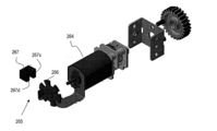
図13は、薬剤注入装置200の装置筐体201を取り外した分解斜視図であり、図14はRF-IDアンテナの配置を示した薬剤注入装置200の斜視図である。図15は、薬剤注入装置200のピストン駆動機構220の分解斜視図である。薬剤注入装置200は、前述した装置筐体201および制御装置280に加えて、ピストン210と、ピストン駆動機構220とを備える。本実施形態では、薬剤注入装置200は、内部筐体202と、メインボード290と、第1サブボード291と、第2サブボード292とをさらに備える。内部筐体202は、ピストン駆動機構220を支持する。メインボード290には、制御装置280およびモータドライバ263が形成されている。また、メインボード290には加速度センサ276も配置されている。
(Drug injection device 200)
FIG. 13 is an exploded perspective view of the
RF-IDリーダ277は、アンテナ278と、送受信回路279とを含む。送受信回路279は例えば、メインボード290に形成されている。第2サブボード292には、選択ボタン256、決定ボタン257および注射ボタン258と、第2温度センサ273が配置されている。第2温度センサ273は、動作時に、装置筐体201内の種々の部品が発する熱の影響を受けにくい位置に配置されていることが好ましい。
The RF-
薬剤注入装置200に薬剤カートリッジ10が挿入されたカセット100が装填された状態で、RF-IDリーダ277は、薬剤カートリッジ10から送信される第1温度情報およびRFタグ16のメモリに記憶された薬剤の種類を示す情報を含む薬剤情報を読み取る。薬剤注入装置200は、これらの情報に基づき、ピストン210を移動させることによって、薬剤カートリッジ10の薬剤を操作者に注射する。以下、主として薬剤注入装置200のRF-IDリーダ277およびピストン駆動機構220の構造を説明する。When the
<RF-IDリーダ277>
前述したようにRF-IDリーダ277は、アンテナ278と送受信回路279とを含む。図14に示すように、アンテナ278は、それぞれが独立して外部からの信号を受信可能な第1部分278Aおよび第2部分278Bを含む。アンテナ278の第1部分278Aおよび第2部分278Bは、筐体空間201cに隣接して配置されている。第1部分278Aおよび第2部分278Bは、それぞれ概ね平面状の放射導体を含み、互いに直交して配置されていることが好ましい。
<RF-
As described above, the RF-
図16Aおよび図16Bは、薬剤カートリッジ10が挿入されたカセット100が薬剤注入装置200に装填された状態におけるRFタグ16と、アンテナ278の第1部分278Aおよび第2部分278Bとの位置関係を模式的に示す。図16Aおよび図16Bにおいて、カセット100は示していない。本実施形態では、薬剤カートリッジ10は、円筒形状を有しており、長手方向に垂直な断面の外形は概ね円形状を有している。このため、カセット100のカセット柱状空間110cに対して軸周りにどの向き(角度)でも挿入が可能である。このため、カセット100が薬剤注入装置200に装填されたとき、平板状のRFタグ16は、任意の方向を向き得る。16A and 16B show a schematic diagram of the positional relationship between the
一方、RFタグ16のアンテナ16aは概ね平面形状を有しており指向性を有する。具体的には、アンテナ16aは、平面形状に対して垂直な方向に大きな電界強度分布を持つ電磁波を送信する。このため、RF-IDリーダ277のアンテナ278が、1方向にのみ高い受信感度を有していると、アンテナ278の受信感度が高い方向と、RFタグ16のアンテナ16aから送信される電磁波の電界強度が強い方向とが直交あるいは直交に近い関係となり、RFタグ16から送信される電磁波を正しく受信できない可能性がある。On the other hand, the
本実施形態では、アンテナ278の第1部分278Aおよび第2部分278Bが互いに直交して配置されていることによって、アンテナ278は直交する2方向に高い感度を有する。このため、例えば、図16Aに示すように、RFタグ16のアンテナ16aが概ねy方向に垂直に広がっている場合には、アンテナ278は、第1部分278Aでは強い感度でRFタグ16のアンテナ16aからの電磁波を受信することはできないが、第2部分278Bでは十分な感度でRFタグ16のアンテナ16aからの電磁波を受信できる。また図16Bに示すように、RFタグ16のアンテナ16aが概ねx方向に垂直に広がっている場合には、アンテナ278は、第2部分278Bでは強い感度でRFタグ16のアンテナ16aからの電磁波を受信することはできないが、第1部分278Aでは十分な感度でRFタグ16のアンテナ16aからの電磁波を受信できる。図16Aおよび図16Bに示す方向以外にRFタグ16のアンテナ16aが向いている場合にも、アンテナ278の第1部分278Aまたは第2部分278Bによって、十分に高い感度でRFタグ16のアンテナ16aからの電磁波を受信することができる。よって、本実施形態の薬剤注入装置200によれば、カセット100内の薬剤カートリッジ10から、より確実に第1温度情報およびRFタグ16のメモリに記憶された薬剤の種類を示す情報を含む薬剤情報を読み取ることが可能である。In this embodiment, the
薬剤カートリッジ10に取り付けられたRFタグ16からの情報は、例えば、以下の手順によって、RF-IDリーダ277によって読み取られる。まず、RFタグ16に情報を送信させるための電力をRFタグ16に生成させるため、RF-IDリーダ277の送受信回路279から起動用の信号を生成し、アンテナ278の第1部分278Aおよび/または第2部分278Bから電磁波を送信する。RFタグ16のアンテナ16aが電磁波を受信すると、アンテナ16aが電磁波を受信し、共振によって起電力が生成する。生成した起電力によって、IC16bが起動し、記憶部に記憶さえている情報を読み出して信号化する。また、第1温度センサが検出する温度を信号化する。生成した信号は、IC16bからアンテナ16aに送られ、アンテナ16aから電磁波が送信される。RF-IDリーダ277は、アンテナ278の第1部分278Aまたは第2部分278BによってRFタグ16からの電磁波を受信し、送受信回路279によって信号に変換される。これにより、第1温度情報およびRFタグ16のメモリに記憶された薬剤の種類を示す情報を含む薬剤情報が得られる。これらの情報は、制御装置280に送信される。Information from the
<ピストン駆動機構220>
図14および図15を参照する。ピストン210は、先端部211と先端部211に接続された本体212とを含む。先端部211は、第1端210a側に位置している。先端部211は、本実施形態では、円柱を軸に沿った2つの平行な2平面で切断したIカット形状を有している。先端部211は、カセット100のカセットキャップ130に設けられたキャップ開口130dに対応した形状を有している。
<
14 and 15. The
ピストン210は、本体212の側面に位置する駆動凸部213を含む。駆動凸部213は、後述するようにピストン駆動機構220に設けられるガイド231と係合することによって、ガイド231の形状にしたがって、回転を規制する。本実施形態では、駆動凸部213はピストン210の側面に設けられているリブであり、リブは、ピストン210の軸に平行に延びるリッジ状の凸部である。本実施形態では、ピストン210は、本体の側面の第2端210b側に配置された2つの駆動凸部213を有する。ピストン210の本体212には、ピストン210の軸に沿って延びる穴210hの内側に位置する雌ネジ214が設けられている。The
ピストン駆動機構220は、モータ264と、ギアボックス221と、駆動ギア222と、駆動ロッド235と、ピストンガイド230とを含む。モータ264、ギアボックス221、駆動ギア222およびピストンガイド230が内部筐体202に支持されている。The
モータ264は、制御装置280の制御に基づき正転または逆転する。ここで、正転とは、ピストン210を前進させる方向に回転することをいい、逆転とは、ピストン210を後退させる方向に回転することをいう。The
モータ264の回転軸には回転量検出器としてロータリーエンコーダ265が取り付けられており、ロータリーエンコーダ265がモータ264の回転量(回転数)を検出する。ロータリーエンコーダ265は、エンコーダプレート266と、発光素子および受光素子を含むパルスエンコーダ267とを含む。ロータリーエンコーダ265については以下において詳述する。A
ギアボックス221は、モータ264の回転軸に取り付けられた少なくとも1つのギアを含む。ギアボックス221はモータ264の回転速度を減速するために2以上のギアを含んでいてもよい。The
駆動ギア222は、ギアボックス221のギアとかみ合い、ベアリング223によって回転可能に内部筐体202に支持される。駆動ギア222の軸に穴が設けられており、駆動ロッド235の一端が挿入され嵌合している。The
駆動ロッド235は棒形状を有し、側面に雄ねじ236が形成されている。雄ねじ236は、ピストン210に設けられた雌ネジ214に噛み合うように、ねじ山の高さ、形状、ねじのピッチ等が構成されている。The
ピストンガイド230は、ピストン210が挿入される穴230hを有している。穴230hの内側面には、ガイド231が設けられている。ガイド231は、ピストン210の駆動凸部213と係合し、ピストン210を軸周りに回転させることなく前進または後退するように案内する。The
ガイド231は、本実施形態では、穴230hの軸に平行に延びる直線溝であり、ピストン210の側面に設けられた駆動凸部213であるリブが挿入される。ピストンガイド230は、ピストン210の2つの駆動凸部213に対応して2つのガイド231を備える。In this embodiment, the
制御装置280の指令によって、モータ264が正転すると、ギアボックス221を介して駆動ギア222が回転し、駆動ロッド235が回転する。駆動ロッド235が回転すると、駆動ロッド235の雄ねじ236とかみ合ったピストン210の雌ネジ214は軸周りの回転力を受ける。ピストン210の駆動凸部213がガイド231の溝に挿入されているため、ガイド231によって、ピストン210は軸周りの回転が規制され、駆動ロッド235の回転に従い、ピストン210は回転することなく前進する。When the
制御装置280の指令によって、モータ264が逆転すると、ギアボックス221を介して駆動ギア222が回転し、駆動ロッド235が逆の方向に回転する。駆動ロッド235の雄ねじ236とピストン210の雌ネジ214とがかみ合い、軸周りの回転が規制されることによって、ピストン210は軸周りに回転することなく後退する。When the
<ピストン駆動機構220の制御>
前述したように液体の薬剤14の粘度は温度によって変化する。一般に、薬剤の温度が高いほど、粘度は小さくなる。また、薬剤の種類によって粘度は異なる。さらに、同じ薬剤が薬剤カートリッジに収納されていても、シリンダ11の容量が異なることによって、シリンダ11の直径が異なると、ガスケット13を移動させるのに要する負荷が異なり得る。従来の薬剤注入装置では、薬剤の種類や薬剤カートリッジ10の容量によらず、円滑な注入動作を行うことが可能なように、対応している薬剤および薬剤カートリッジのうち、最も粘度が高い薬剤および最も負荷が大きい薬剤カートリッジに対応可能な十分に高い駆動電圧をモータに供給していた。しかし、この場合、最大出力が大きな二次電池を用いる必要がある。このため二次電池の容積も大きくなり、薬剤注入装置が大型になったり、重くなったりする。また、常に必要以上の電力でモータを駆動するため、消費電力が大きくなってしまう。
<Control of
As mentioned above, the viscosity of the
また、冷たい薬剤を注射すると痛みを感じる場合があるという課題に対し、従来の薬剤注入装置では、操作者が注射を行う前に一定時間薬剤カートリッジを室内で放置することで対応していた。一定時間放置するというような時間管理は、操作者には面倒であり、また、注射を行う際の室内の温度は季節や場所等によって異なり得るため、同じ時間放置しても、薬剤カートリッジが同じ温度になるとは限らない。 In addition, to address the issue that injection of cold medicine can cause pain, conventional drug injection devices have the operator leave the medicine cartridge indoors for a certain period of time before injecting. Time management, such as leaving it for a certain period of time, is troublesome for the operator, and since the room temperature when an injection is performed can vary depending on the season, location, etc., the medicine cartridge does not necessarily reach the same temperature even if it is left for the same period of time.
本実施形態では、薬剤カートリッジのRFタグ16から送信される薬剤カートリッジ内の薬剤の種類を示す情報を含む薬剤情報、および、第1温度センサが検出する第1温度情報を、RF-IDリーダ277によって受信し、第1温度情報に基づいたモータの駆動電力を決定し、決定した駆動電力を出力するように、モータドライバを制御する。また、第1温度情報が示す温度がある温度範囲にある場合には、注射に適した温度ではないと判断してモータ264の駆動をしないことによって、注射動作を開始しない。In this embodiment, drug information including information indicating the type of drug in the drug cartridge transmitted from the
このような制御を行うため、メモリ254には、複数の薬剤ごとについてのモータ264を制御するための制御情報が記憶されている。各薬剤についての制御情報は、複数の温度範囲のそれぞれに対するモータの制御パラメータのセットを含んでいる。To achieve this control,
表1は、メモリ254に記憶されているモータの制御パラメータのセットの一例を示している。複数の薬剤の一例として薬剤Aおよび薬剤Bを示している。薬剤Bの粘度は薬剤Aの粘度よりも高い。また、複数の温度範囲として、0℃未満、0℃以上10℃未満、10℃以上20℃未満、20℃以上38℃未満および38度以上の温度範囲を示している。0℃、38℃および10℃は、それぞれ、第1温度、第2温度および第3温度の一例である。カセット100に薬剤カートリッジ10が挿入されていない場合、RF-IDリーダ277は、薬剤情報および第1温度情報のいずれも取得することができない。メモリ254は、このような薬剤カートリッジがない場合のモータの制御パラメータのセットをさらに備えていてもよい。Table 1 shows an example of a set of motor control parameters stored in

第1温度情報が0℃未満の場合、薬剤が凍結している可能性がある。また、第1温度情報が38℃以上である場合、高温で保管されることによって、薬剤が変質している可能性がある。第1温度情報がこれら2つの温度範囲にある場合には、注射を行うことが好ましくない。このため、薬剤情報の薬剤の種類がAかBかにかかわらず駆動情報Cが割り当てられる。駆動情報Cは、例えば、モータ264を駆動しないという情報であってよい。薬剤カートリッジがカセット100に挿入されていない場合には、いずれの温度範囲であっても注射を行うことができないため、すべての温度範囲において駆動情報Cが割り当てられている。0℃以上10℃未満、10℃以上20℃未満、20℃以上38℃未満の温度範囲には、薬剤Aおよび薬剤Bに対して駆動情報A1、A2、A3および駆動情報B1、B2、B3の制御パラメータセットがそれぞれ割り当てられている。
If the first temperature information is less than 0°C, the medicine may be frozen. If the first temperature information is 38°C or higher, the medicine may be altered due to storage at high temperature. If the first temperature information is within these two temperature ranges, it is not preferable to perform an injection. For this reason, regardless of whether the type of medicine in the medicine information is A or B, the driving information C is assigned. The driving information C may be, for example, information that the
表2は、駆動情報A1、A2、A3および駆動情報B1、B2、B3の制御パラメータセットの具体的な一例を示す。モータの駆動電力の調整は、例えば印加する電圧を調整してもよいし、他の方法で調整してもよい。本実施形態では、PWM(パルス幅変調)によって駆動電力を調整し、モータを制御する。図17は、PWMによる駆動信号および駆動信号によって回転するモータの回転速度の一例を示す。PWMによる駆動信号を定義する駆動情報は、例えば、デューティー比初期値、デューティー比増加幅、増加期間、増加最大待ち時間および目標到達デューティー比を含む。 Table 2 shows a specific example of the control parameter set of drive information A1, A2, A3 and drive information B1, B2, B3. The motor drive power may be adjusted, for example, by adjusting the applied voltage, or by other methods. In this embodiment, the drive power is adjusted by PWM (pulse width modulation) to control the motor. Figure 17 shows an example of a PWM drive signal and the rotation speed of a motor rotated by the drive signal. The drive information defining the PWM drive signal includes, for example, an initial duty ratio value, a duty ratio increase width, an increase period, a maximum increase waiting time, and a target duty ratio.
全温度範囲において、薬剤Bの粘度は薬剤Aの粘度よりも高い。このため、各温度範囲を比較した場合、デューティー比初期値の初期値は、薬剤Aよりも薬剤Bのほうが大きい。これは、粘度の高い薬剤を駆動するのにより大きな駆動電力が必要だからである。本実施形態では、増加期間、増加最大待ち時間は薬剤Aよりも薬剤Bのほうが短く、目標デューティー比は各温度範囲で薬剤Aよりも薬剤Bのほうが大きい。 Over the entire temperature range, the viscosity of drug B is higher than that of drug A. Therefore, when comparing each temperature range, the initial duty ratio is higher for drug B than for drug A. This is because a larger driving power is required to drive a drug with a higher viscosity. In this embodiment, the increase period and maximum increase waiting time are shorter for drug B than for drug A, and the target duty ratio is higher for drug B than for drug A over each temperature range.
また、各薬剤では、温度範囲が高くなるにつれて、パラメータの値は小さくなっている。つまり、各温度範囲の下限値が高いほど、デューティー比初期値、デューティー比増加幅、増加期間、増加最大待ち時間および目標到達デューティー比は小さい。これは、薬剤の温度が高いほど粘度が小さくなり、駆動によるする電力も小さくて済むからである。 In addition, for each drug, the parameter values become smaller as the temperature range increases. In other words, the higher the lower limit of each temperature range, the smaller the initial duty ratio, duty ratio increase range, increase period, maximum increase wait time, and target duty ratio become. This is because the higher the drug temperature, the lower the viscosity, and the less power required for driving.

例えば、薬剤情報が薬剤Aであり、第1温度情報が15℃である場合、制御装置280は、メモリ254から駆動情報A2を読み出し、駆動情報A2に含まれるパラメータを用いて、モータドライバ263を駆動する。For example, if the drug information is drug A and the first temperature information is 15°C, the
表2および図17に示すようにA1~A3およびB1~B3のいずれの駆動情報を選択しても、デューティー比が段階的に大きくなることによって、制御装置280は、モータに流れる電流が段階的に増大するようにモータドライバに駆動信号を生成させる。デューティー比が目標デューティー比に到達したら、その後、目標デューティー比で駆動を続ける。このようにモータの起動時に、薬剤の粘度に応じたデューティー比の初期値で、かつ、段階的にデューティー比が大きくなるPWM制御を行うことによって、始動(起動)電流のピーク値(電流のオーバーシュート)を小さくすることができる。As shown in Table 2 and FIG. 17, regardless of whether drive information A1-A3 or B1-B3 is selected, the duty ratio increases stepwise, and the
図18Aは、PWM制御を行わない場合に生じる始動電流を示し、図18Bは、本実施形態のPWM制御による始動電流の一例を示す。図18Aに示すように、PWM制御を行わない場合、最大で800mA程度のピーク電流が流れる。これに対し本実施形態によれば、ピーク電流を400mA程度に抑制することができる。 Figure 18A shows the starting current that occurs when PWM control is not performed, and Figure 18B shows an example of the starting current by PWM control of this embodiment. As shown in Figure 18A, when PWM control is not performed, a peak current of up to about 800 mA flows. In contrast, according to this embodiment, the peak current can be suppressed to about 400 mA.
薬剤の粘度に応じたデューティー比の初期値を用いることは、特に、モータ264が定常状態になるまでの時間の短縮に寄与する。デューティー比の初期値を薬剤の粘度に応じて変更しなくても、段階的にデューティー比が大きくなるパルス信号でモータ264を駆動すれば、起動時の電流のオーバーシュートは抑制し得る。しかし、粘度に応じた適切なデューティー比の初期値を用いなければ、薬剤カートリッジ10のガスケットが始動し、一定の速度で移動するまでに要する時間が非常に長くなってしまう場合がある。このため、注射に要する時間が長くなり、実用的ではなくなったり、操作者への負担が大きくなることが考えられる。Using an initial value of the duty ratio according to the viscosity of the drug particularly contributes to shortening the time until the
本実施形態では、薬剤の種類による粘度の差異および温度による粘度の差異を考慮してデューティー比初期値等のPWM制御全体のパラメータを設定することにより、モータ264が定常状態になるまでの時間が長くなることを抑制しつつ、始動電流を小さくすることができる。これにより、最大放電電流を小さくできるため、二次電池の容量を小さくすることが可能となる。よって、より小さな容量の二次電池を搭載しても、適切な駆動力で注射を行うことが可能な薬剤注入装置を実現することが可能である。本実施形態の薬剤注入装置によれば、駆動電力を調整しない場合に比べて、例えば、20~30%程度電池容量を小さくすることできる。したがって、小型で、かつ、より軽量の薬剤注入装置を実現することができ、取り扱いやすく、優れた操作性を提供することが可能となる。In this embodiment, the parameters of the entire PWM control, such as the duty ratio initial value, are set taking into account the difference in viscosity due to the type of drug and the difference in viscosity due to temperature, thereby suppressing the time until the
前述したように、薬剤カートリッジ10のRFタグ16から送信される第1温度情報は、注射に適した温度であるか否かを判断するためにも用いることが可能である。以下、図19Aおよび図19Bを参照しながら、第1温度情報を注射の適否の判断にも利用した注射動作の一例を示す。図19Aおよび図19Bは、注射動作時における薬剤注入装置200の動作を説明するフローチャートである。図5およびこれらの図を参照して、注射動作説明する。As mentioned above, the first temperature information transmitted from the
操作者が薬剤注入装置200にカセット100を装填すると、制御装置280は、RF-IDリーダ277の送受信回路に、RFタグ16に情報を送信させるための起電力を発生させるための信号を送信させる(S1)。RF-IDリーダ277が、RFタグ16からの信号を受信できない場合には、カセット100に薬剤カートリッジ10が挿入されていないことを意味する。この場合には、制御装置280はメモリ254から駆動情報Cを読み込み(S2)、駆動情報Cでモータ264を駆動する(S3)。駆動情報Cは、例えば、モータ264が停止した状態を維持するようにモータドライバ263を制御する情報である。When the operator loads the
RF-IDリーダ277が、RFタグ16からの信号を受信した場合には(S4)、制御装置280は、薬剤カートリッジ10のRFタグ16から送信された、薬剤カートリッジ10内の薬剤の種類を示す情報を含む薬剤情報および第1温度センサが検出する第1温度情報をT0としてメモリ254に記憶させる。T0は初期温度として後述する薬剤が適温になるまでの時間の予測にも用いられる。When the RF-
制御装置280は、取得した第1温度情報の示す温度と、基準温度とを比較する(S5)。基準温度は、0℃(第1温度)、20℃(第3温度)および38℃(第2温度)である。第1温度情報の示す温度が0℃未満である場合、あるいは、38℃以上である場合(第1温度範囲)、薬剤カートリッジ10内の薬剤が凍結しているか、または、高温のため変質している可能性がある。このため、制御装置280は、例えば表示装置259に薬剤カートリッジ10の交換を促す画面を表示させ(S6)、薬剤注入動作を終了させる。The
第1温度情報の示す温度が0℃以上20℃未満である場合(第2温度範囲)、薬剤の温度が低く注射の際痛みが感じられる可能性がある。このため、制御装置280は、例えば表示装置259に薬剤の温度が上昇するまで注射を待つように促す画面を表示させる(S7)。この場合、操作者は、多少痛みを感じても早く注射を行いたいと判断することが考えられるので、注射を選択するか、または、待機を選択するかの入力を受け付ける(S8)。操作者が待機を選択した場合には、リマインド動作のフローへと進む。一方、操作者が注射を選択する場合には、投与動作のフローに進む。
When the temperature indicated by the first temperature information is between 0°C and 20°C (second temperature range), the temperature of the medicine is low and pain may be felt during injection. For this reason, the
第1温度情報の示す温度が20℃以上38℃未満である場合(第3温度範囲)、注射を行うことが可能である。このため、投与動作のフローへ進む。If the temperature indicated by the first temperature information is equal to or higher than 20°C and lower than 38°C (third temperature range), it is possible to perform the injection. Therefore, the flow proceeds to the administration operation.
図19Bに示すように、投与動作のフローでは、制御装置280は、まず、薬剤情報が薬剤Aであるか薬剤Bであるかを判定する(S11)。薬剤情報が薬剤Aである場合、第1温度情報と基準温度とを比較し(S12)、比較結果に応じた駆動情報をメモリ254から読み出す。表1、2に示すように、第1温度情報の示す温度が0℃以上10℃未満である場合には、駆動情報A1を、10℃以上20℃未満である場合には、駆動情報A2を、20℃以上38℃未満である場合には駆動情報A3をそれぞれメモリ254から読み出す(S14、S15、S16)。薬剤情報が薬剤Bである場合にも同様に、第1温度情報と基準温度とを比較し(S13)、比較結果に応じた駆動情報をメモリ254から読み出す。第1温度情報の示す温度が0℃以上10℃未満である場合には、駆動情報B1を、10℃以上20℃未満である場合には、駆動情報B2を、20℃以上38℃未満である場合には駆動情報B3をそれぞれメモリ254から読み出す(S17、S18、S19)。
As shown in FIG. 19B, in the flow of the administration operation, the
制御装置280は選択された駆動情報のパラメータを用いて、モータドライバ263を制御し、前述したようにモータ264をPWM制御により回転させる。The
次にリマインド動作を説明する。薬剤の温度が低く、操作者が薬剤の温度が適温になるまで注射を待つことを選択した場合、薬剤注入装置200の制御装置280はリマインド動作を行う。図19Cは、リマインド動作の一例を示すフローチャートである。Next, the remind operation will be described. If the temperature of the medicine is low and the operator selects to wait until the medicine reaches an appropriate temperature before injecting, the
リマインド動作では、制御装置280が、薬剤カートリッジ10に貼付された第1温度センサ15から第1温度情報を逐次受け取り、薬剤の温度が適温になった場合にその旨報知を行う。本実施形態ではさらに適温になるまでに要する時間を予測し、予想時間を報知する。このために、制御装置280は、第2温度センサ273から第2温度情報を受け取り、第2温度情報が所定の温度以上である場合、所定の時間間隔で第1温度情報を逐次取得する。制御装置280は、取得した第1温度情報および第2温度情報に基づき、注射可能となるまでの予測時間を逐次算出し、算出した予測時間を示す情報を表示するように表示装置を制御する。In the reminding operation, the
具体的には、まず、制御装置280は、第2温度センサ273から第2温度情報を受け取り、第2温度情報が20℃以上であるか否かを判定する(S21)。第2温度センサ273が出力する第2温度情報は、直接的には、装置筐体201内の温度を示す。しかし、第2温度センサ273が装置筐体201内の構成部品等から発する熱の影響を受けにくい場合には、第2温度情報は、薬剤注入装置200が使用される環境温度とほぼ一致する。薬剤の温度は、薬剤カートリッジ10を冷蔵庫などから取り出して室内に保持することによって、室温まで上昇するので、室温が20℃未満であれば、薬剤カートリッジ10を室内に保持しても、薬剤の温度が20℃、つまり、注射に適した温度に達することは難しい。このため、第2温度情報が20℃未満である場合には、制御装置280は、例えば、表示装置259に室温が低いので注射できないことを知らせる画面を表示させ(S35)、リマインド動作を終了させる。Specifically, first, the
第2温度情報が20℃以上である場合、制御装置280は、上述した最初に取得した薬剤カートリッジの温度T0をT1として記憶する(S22)。また、制御装置280は、第1温度情報を取得するタイミングを調整する。前回、または、最初に第1温度情報を取得した時刻から1分経過した場合には、次のステップにすすむ(S23)。If the second temperature information is 20°C or higher, the
制御装置280は、薬剤注入装置200の電源の状態を判定する(S24)。オートパワーオフなどで、OFF状態になっている場合には、電源をONにし(S25)、次のステップに進む。電源がON状態であれば、そのまま次のステップに進む。The
制御装置280は、第1温度情報を取得し、現在の測定値T2として記憶する(S26)。続いて、T2と、直前(1回前)の第1温度情報の測定値であるT1との差を求める(S27)。T2とT1との差が1以上である場合、薬剤の温度が急激に上昇しており、薬剤が適温になるまでに要する時間を適切に予測するのが困難である。このため、再度一定時間経過するまで待機を行う。具体的には、まず、最新の第1温度情報T2をT1として記憶し(S31)、電源の状態を判定する(S32)。オートパワーモードである場合には、電源をOFFにし(S33)、1分間の待機を行うステップ(S23)へ戻る。オートパワーモードではない場合には、電源の状態は変化させずに、1分間の待機を行うステップ(S23)へ戻る。The
T2とT1との差が1未満である場合(S27)、制御装置280は薬剤カートリッジ10の温度、言い換えると薬剤の温度が、あとどれくらいの時間で適温になるかを計算する。If the difference between T2 and T1 is less than 1 (S27), the
本願発明者の詳細な検討によれば、低温で保管されていた薬剤カートリッジ10を室内で保管するなど、注射を行う環境温度で保持した場合、直後の温度上昇の速度は、薬剤カートリッジ10のサイズや保持されている薬剤の量などによって異なり得る。しかし、温度上昇の速度が小さくなってくれば、その後の温度上昇の速度は、薬剤カートリッジ10のサイズおよび薬剤の量によらず、ほぼ同じになることが分かった。より具体的には、T2とT1の差が1℃未満になった場合には、その後の温度上昇の速度は、薬剤カートリッジ10のサイズおよび薬剤の量によらず、ほぼ同じであり、薬剤の温度は、初期温度TOを取得した時刻からの経過時間で近似できることが分かった。According to detailed studies by the inventors of the present application, when a
例えば、T2とT1の差が1℃未満になった場合、経過時間をxとしたときの経過時間から推定される薬剤の温度f(x)は、環境温度と言える第2温度情報の温度範囲に応じて、以下の関数で示される。
(1) 第2温度情報が25℃以上30℃未満の場合

![]()
(1) When the second temperature information is equal to or higher than 25°C and lower than 30°C
![]()
例えば、第2温度情報が25℃である場合、式(1)を用いてT2とT1の差が1℃未満になった時刻以降の薬剤の温度は、経過時間を用いて予測できる。T2とT1の差が1℃未満になったときの、初期温度TOを取得した時刻からの経過時間をtnで表す。tnから1分毎に経過した時刻をtn+1、tn+2、tn+3、・・・tn+iとし、tnのときの第1温度情報T2をT2nとした場合、tnからi分後における予測される薬剤の温度T(i)は、以下の式で示される。
![]()
![]()
注射に適した薬剤の温度を例えば20℃以上であるとした場合、制御装置280は、T2とT1との差が1未満になったときの経過時間tnと、式(1)とを用いてf(tn)を求める。また、i=1の場合である、f(tn+1)を求める。この2つの値と、第1温度情報T2nとから、T(1)を求める。T(1)が20℃未満である場合には、制御装置280はT(i)が20℃以上になるまでiを1つずつ増大させて同様に計算を行う。T(i)が20℃以上になった場合、制御装置280は、その時のiを予想時間として決定する。
If the temperature of the medicine suitable for injection is, for example, 20° C. or higher, the
制御装置280は、この時(現在)の第1温度情報T2nが20℃未満であるかどうかを判定し(S29)、20℃未満である場合には、制御装置280は、表示装置259に、予測時間の報知、つまり、i分後薬剤が適温になる旨の画面を表示させる(S30)。予測時間の報知は、表示装置259に限られず、制御装置280は、通信部262を用いて操作者のスマートフォン、タブレット端末などの携帯機器に予測時間を送信し、これら携帯機器に表示などの報知を行わせてもよい。
The
その後、最新の第1温度情報T2をT1として記憶し(S31)、電源の状態を判定する(S32)。オートパワーモードである場合には、電源をOFFにし(S33)、1分間の待機を行うステップ(S23)へ戻る。オートパワーモードではない場合には、電源の状態は変化させずに、1分間の待機を行うステップ(S23)へ戻る。さらに、ステップS23~S29までを繰り返し、適温になるまでの時間を予測する。2回目以降、適温になるまでの時間を予測する場合には、初期温度TOを取得した時刻からその時までの経過時間をtnと第1温度情報T2nとを用いる。時間予想に逐次新しい実測値である第1温度情報T2nを用いることによってより正確な予測を行うことができる。 Then, the latest first temperature information T2 is stored as T1 (S31), and the state of the power supply is judged (S32). If the mode is auto power mode, the power supply is turned off (S33), and the process returns to the step of waiting for one minute (S23). If the mode is not auto power mode, the power supply state is not changed, and the process returns to the step of waiting for one minute (S23). Furthermore, steps S23 to S29 are repeated to predict the time until the appropriate temperature is reached. From the second time onwards, when predicting the time until the appropriate temperature is reached, the elapsed time t n from the time when the initial temperature TO was acquired to that time and the first temperature information T2 n are used. By using the first temperature information T2 n , which is a successively new measured value, for the time prediction, a more accurate prediction can be made.
2回目以降の時間予測において、制御装置280は、第1温度情報T2nが20℃未満であるかどうかを判定し(S29)、20℃以上である場合には、表示装置259に、適温になった旨の画面を表示させ(S34)、リマインド動作を終了する。その後、図19Aに示すように、投与動作へ進む。
In the second and subsequent time predictions, the
表3に計算例を示す。初期温度TOを取得した時刻からの5分経過後(n=5)に、T2とT1の差が1℃未満になったとし、この時の第1温度情報T25を13.45℃とする。 A calculation example is shown in Table 3. It is assumed that the difference between T2 and T1 becomes less than 1°C after 5 minutes (n=5) have elapsed since the time when the initial temperature TO was acquired, and the first temperature information T25 at this time is 13.45°C.

i=1つまり、この時点から1分経過後(初期温度TOを取得してから6分後)に予測される薬剤の温度は14.3555℃である。i=10の場合に、予測される薬剤の温度は20.075℃となり、20℃以上になるため、適温になる予測時間は10分後であると決定される。上述したように、1分経過後に再度時間予測の計算を行う場合には、実測値T26の値が用いられる。 i=1, that is, the predicted temperature of the medicine one minute after this point (six minutes after the initial temperature TO is acquired) is 14.3555° C. When i=10, the predicted temperature of the medicine is 20.075° C., which is above 20° C., and it is determined that the predicted time to reach the optimum temperature is 10 minutes later. As described above, when calculating the time prediction again after one minute has passed, the actual measured value T26 is used.
このように本実施形態によれば、あと何分で薬剤が適温になり注射が可能となるかが報知されるため、適温になるまでの時間の使い方を操作者が決定することが可能となる。 In this way, according to this embodiment, the operator is notified of the number of minutes remaining until the medication reaches the appropriate temperature and can be injected, allowing the operator to decide how to use the time until the medication reaches the appropriate temperature.
なお、本実施形態では、リマインド動作において、薬剤が適温になるまでの予測時間を計算しているが、予測時間を計算し報知しなくてもよい。つまり、所定の時間間隔で第1温度情報を取得し、第1温度情報が所定の温度以上になった場合に、薬剤が適温になり、注射が可能となったことを報知してもよい。In this embodiment, the reminding operation calculates a predicted time until the medication reaches the appropriate temperature, but it is not necessary to calculate and notify the predicted time. In other words, the first temperature information may be acquired at a predetermined time interval, and when the first temperature information reaches or exceeds a predetermined temperature, a notification may be issued that the medication has reached the appropriate temperature and can be injected.
<タッチセンサ275>
図1および図13に示すように、薬剤注入装置200の凸部201tの皮膚あて面201eにはタッチセンサ275が配置されている。これにより、皮膚あて面201eが確実に皮膚と接触している状態を検出することができ、注射時に針22が皮膚から完全に離れてしまう前に薬剤注入装置200のぐらつき等の不適切な保持状態を検出することができる。以下、タッチセンサ275を詳細に説明する。
<
1 and 13, a
タッチセンサ275は、表面チャージ転送方式のタッチセンサである。タッチセンサ275は、皮膚あて面201eに配置されたセンサーコンデンサCxと、制御装置280に組み込まれたサンプリングコンデンサCsおよび制御回路とを含む。タッチセンサ275の制御回路は、まず、センサーコンデンサCxおよびサンプリングコンデンサCsを放電して、タッチセンサ275をリセットする。その後、タッチセンサ275の制御回路は、センサーコンデンサCxを充電し、センサーコンデンサCxに充電された電荷をサンプリングコンデンサCsに転送する。この充電及び転送動作を繰り返し、サンプリングコンデンサCsに電荷を逐次に蓄積していく。制御回路は、サンプリングコンデンサCsの電圧をモニターしており、電圧が所定の値を超えた時、その時までに繰り返された転送回数Nを出力する。この転送回数Nは、センサーコンデンサCxの容量に反比例しており、センサーコンデンサCxの容量が増大すると、転送回数Nは減少する。薬剤注入装置200の凸部201tの皮膚あて面201eが操作者等の皮膚に接触している場合、センサーコンデンサCxの容量は増大するため、センサーコンデンサCxに蓄積される電荷も増え、1回の転送動作でサンプリングコンデンサCsに転送される電荷量も増える。よって、サンプリングコンデンサCsの電圧が所定の値を超えるまでの転送回数Nは減少する。The
図20は、薬剤注入装置200を用いてタッチセンサ275の検出感度を確認した結果の一例を示している。図20において、Nが900回程度の値の結果は、皮膚あて面201eが皮膚に接触しているときの結果を示し、Nが1300回程度の値の結果は、皮膚あて面201eが皮膚に接触していないときの結果を示している。図20から、皮膚あて面201eが皮膚に接触しているときと接触していないときの転送回数Nには大きな差異があり、皮膚が接触しているか否かは、転送回数Nを利用すれば、明瞭に判別可能であることが分かる。上述の例では、例えば1050回以下の転送回数であれば皮膚と接触していると判断し、1100回以上の転送回数であれば、皮膚が離れていると判断してもよい。
Figure 20 shows an example of the results of checking the detection sensitivity of the
表面チャージ転送方式のタッチセンサにおける1回の転送動作に要する時間は、例えば、0.5マイクロ秒から4マイクロ秒程度であり、サンプリングコンデンサCsの電圧が所定の値を超えるまでに要する時間は、2ミリ秒から8ミリ秒程度である。皮膚あて面201eの面積は比較的小さく、注射を行う部位によっては、注射時に薬剤注入装置200の保持する姿勢が安定しにくいことも考えられるため、例えば、連続して5回~8回、皮膚の接触を検出した場合に、薬剤注入装置200が正しく保持されており、注射を行うことが可能な状態にあると判定してもよい。例えば、5回連続して1050回以下の転送回数を検出した場合には、タッチセンサ275が皮膚の接触を検出していると判断し、その他の場合には、タッチセンサ275が皮膚の離隔を検出したと判断してもよい。The time required for one transfer operation in a surface charge transfer touch sensor is, for example, about 0.5 to 4 microseconds, and the time required for the voltage of the sampling capacitor Cs to exceed a predetermined value is about 2 to 8 milliseconds. Since the area of the
表面チャージ転送方式のタッチセンサは、ノイズの影響を受けにくいという点で、従来の発振方式のタッチセンサに比べて優れている。このため、従来に比べてより確実に、皮膚あて面201eに皮膚が当接していることを検出することができ、より薬剤注入装置のより安全で確実な取り扱いを実現し得る。The surface charge transfer touch sensor is superior to conventional oscillation touch sensors in that it is less susceptible to noise. This makes it possible to more reliably detect when the skin is in contact with the
図21は、タッチセンサ275を用いた薬剤注入装置200の注射動作を説明するフローチャートである。図21に示すように、制御装置280は、注射の準備動作の開始後、タッチセンサ275が接続されているか否かなどをタッチセンサ275の制御回路によって確認し(S101)、接続されていなければ、故障あるいは異常があることを表示装置259に表示させる(S102)。
Figure 21 is a flow chart explaining the injection operation of the
タッチセンサ275が正しく接続されている場合には、皮膚あて面201eを皮膚に押し当て、注射が可能な状態に薬剤注入装置200を保持するように促す画像、文字等の情報を表示装置259に表示させる(S103)。制御装置280は、タッチセンサ275の制御回路からの検出信号を逐次受け取る。例えば5回連続して1050回以下の転送回数を示す検出信号を受信した場合(以下、皮膚の接触を検出という、S104)、制御装置280は、表示装置259に、注射ボタン258を押下するよう促す情報を表示させる(S105)。If the
制御装置280は、注射ボタン258が押下された信号を検出した場合(S106)、前述した注射動作、つまり、薬剤の注入を行うようにモータドライバ263を制御する(S107)。制御装置280は、薬剤の注入動作中、タッチセンサ275の制御回路からの検出信号を並行して逐次受け取る。皮膚の接触を検出できない場合、つまり、タッチセンサ275が皮膚の離隔を検出した場合(S108)には、制御装置280は、注入動作を中断し、薬剤注入装置200が注射部位から離れたことを示す情報、および、注射を中断するか継続するか否かの入力を促す情報を表示装置259に表示させる(S110)。When the
制御装置280は、注射ボタン258が押下された信号を検出した場合(S111)、タッチセンサ275が皮膚の接触を検出したことを確認して(S112)、注射動作に復帰する(S113)。操作者が注射を中断する入力(例えば、決定ボタン257の入力)を行った場合、制御装置280は、注射動作を終了する。When the
注射動作の終了は、例えば、ロータリーエンコーダ265が検出するパルス数または回転数によって制御装置280が判断し(S109)、注射動作を終了する。The end of the injection operation is determined by the
<加速度センサ276>
本実施形態の薬剤注入装置200は加速度センサ276を備えている。これにより、薬剤注入装置200の姿勢を検出することができ、操作者に薬剤注入装置200の姿勢を変えるように促すことが可能となる。
<
The
図13に示すように、加速度センサ276は例えばメインボード290に配置することができる。加速度センサ276は、互いに直交する第1、第2及び第3軸を有し、軸に沿った加速度または軸周りの角加速度を検出できることが好ましい。また、第1、第2および第3軸の1つがピストンの移動方向と一致するように筐体内に配置されていることが好ましい。本実施形態では、加速度センサ276は、第1、第2および第3軸に沿った加速度を検出する。例えば、図22に示すように、薬剤注入装置200において、ピストン210の移動方向であり、かつ、ピストンの前進方向にy軸の正の方向を一致させ、表示装置259が配置された面の法線ベクトルの方向をz軸にとる。この時x軸は、薬剤注入装置200を上向きに保持した状態における右側面の法線ベクトルの方向と一致する。x軸、y軸およびz軸は、薬剤注入装置200に固定されている。加速度センサ276は、x軸、y軸およびz軸に沿って重力加速度を検出することできるため、薬剤注入装置200の姿勢、例えば、y軸の鉛直方向からの傾きを検出することができる。13, the
このような姿勢の検出結果は、薬剤注入装置200の種々の操作や動作に利用することができる。例えば、注射を行う際、あらかじめ、空気抜き(あるいは空打ちとも呼ばれる)をおこなって、薬剤カートリッジ10内の空気を抜くことが好ましい。この操作は、針22を上に向けた状態でピストン210を移動させることによって、薬剤カートリッジ10の上方に滞留した空気を針22から排出する。しかし、薬剤注入装置200の先端が真上を向かず傾いていると、図23に示すように、薬剤カートリッジ10のシリンダ柱状空間11cの形状に依存して、空気が抜けにくいシリンダ柱状空間11cの角11hに空気が滞留する可能性がある。このような場合に、加速度センサ276を用いることによって、空気抜きに適した姿勢で薬剤注入装置200を保持するように操作者に誘導することが可能である。
Such posture detection results can be used for various operations and movements of the
薬剤注入装置200をどれくらい傾けずに起こした状態で空気抜きを行うことが好ましいかは、薬剤カートリッジ10のシリンダ柱状空間11cにも依存するが、概ね図24に示すように、鉛直方向をy’軸と固定した座標において、薬剤注入装置200のy軸が、鉛直方向から±70°つまり、x’軸に対して70°以上110°以下の範囲であれば、操作者が姿勢合わせ(方向合わせ)をすることが困難に感じることなく、ほぼ空気を正しく排出できると考えられる。The degree to which the
図25は、加速度センサ276を用いて空気抜きを行う動作を行うフローチャートを示す。空気抜き動作を操作者が選択した場合、あるいは、操作者が注射を行う指令を入力した場合において、制御装置280が空気抜きを実行する場合、制御装置280は、薬剤注入装置200を上向きに保持することを操作者に促す情報(薬剤注入装置の姿勢に関する情報)を表示装置259に表示させる(S201)。制御装置280は、加速度センサ276の検出信号、具体的には、x、y、z軸方向の加速度情報を受け取り、水平方向からのy軸の傾きの角度を算出し、傾きに関する判定を行う(S202)。傾きの角度が70°~110°以外の角度である場合には、薬剤注入装置200が傾いているので、制御装置280は、薬剤注入装置200が傾いていること、および、正しく上向きに保持することを操作者に促す情報を表示装置259に表示させる(S203)。
Figure 25 shows a flowchart of the operation of air removal using the
算出した角度が70°~110°である場合には、制御装置280はモータドライバ263を制御して、モータ264を駆動させ、ピストン210を前進させることにより空気抜き動作を開始する(S204)。If the calculated angle is between 70° and 110°, the
ピストンの移動中、制御装置280は、加速度センサ276の検出信号を逐次受け取り、傾きに関する判定を行う(S205)。傾きの角度が70°~110°で以外の角度になった場合には、制御装置280は、モータ264の駆動を停止し、薬剤注入装置200が傾いていること、および、正しく上向きに保持することを操作者に促す情報を表示装置259に表示させる(S207)。さらに、傾きの角度が70°~110°になったら(S208)、モータ264の駆動を再開する(S208)。During the movement of the piston, the
空気抜き動作の終了は、例えば、ロータリーエンコーダ265が検出するパルス数または回転数によって制御装置280が判断し(S206)、空気抜き動作を終了する。The end of the air purge operation is determined by the
このように、加速度センサ276を用いて、薬剤注入装置200の姿勢検知することにより、操作者により適切な薬剤注入装置200の取り扱いに関する情報を提示することができる。In this way, by using the
前述したように本実施形態の薬剤注入装置200は、未使用の状態で液体成分および固体成分が分離して保持された薬剤を含む薬剤カートリッジ10’にも対応している。薬剤カートリッジ10’を用いる場合には、図9A、図9B、図10(a)、図10(b)を参照して説明したように、使用前に液体成分14Aと固体成分14Bを接触させる。しかし、液体成分14Aと固体成分14Bとを接触させただけでは、固体成分14Bは液体成分14Aにすぐには溶解しない場合もある。このため、操作者が薬剤注入装置200を移動させて、液体成分14Aおよび固体成分14Bを混合(撹拌)することが好ましい。加速度センサ276による薬剤注入装置200の姿勢検知は、このような混合動作を行うのにも適している。以下、加速度センサ276を用いた薬剤の混合動作を説明する。As described above, the
図26は、混合動作のフローチャートである。薬剤の移動には、例えば、薬剤注入装置200を上下に揺すったりすることも考えられる。しかし、このような動作を行うと、液体成分14Aが泡立ちやすく、混合後すぐに注射を行うことができないことが考えられる。また、薬剤注入装置200を上下に移動させることによって、薬剤注入装置200を机などの家具にぶつける可能性もあり、好ましくない。本実施形態では、泡立たせずに薬剤をゆっくり混合させるため、図22において、矢印で示すように、薬剤注入装置200を左右に倒す。薬剤注入装置200の姿勢は、図22に示す薬剤注入装置200のy軸の、図27に示すx’y’座標上での角度で示す。x’y’座標は薬剤注入装置200の姿勢によらず固定されている。図27に示すように、x’軸の正方向を0°として、±180°で示す。図27に示すように、-45°から45°の範囲をゾーン1、45°から135°の範囲をゾーン2、-180°から-135°または135°から180°の範囲をゾーン3と定義する。
Figure 26 is a flowchart of the mixing operation. For example, the
制御装置280は、加速度センサ276を用いて算出される薬剤注入装置200のy軸の角度が、所定の順番で、ゾーン1の範囲、ゾーン2の範囲、およびゾーン3の範囲に入ることを判定することで、操作者が正しく薬剤注入装置200を揺動させ、薬剤を混合させていることを判定する。The
図26に示すように、まず、使用前に液体成分14Aと固体成分14Bを接触させた後(自動溶解動作)、制御装置280は、上述した揺動操作を行うことを促す情報を表示装置259に表示させる(S301)。続いて、揺動回数をカウントするため、カウンターをリセットする(S302)。操作者は、図28に示すように、P1、P2、P3、P4、P1の順で薬剤注入装置200を左右に倒す。この時、制御装置280は、加速度センサ276からの検出信号を受け取り、y軸の傾きが、ゾーン1(-45°~45°)(S303)、ゾーン2(45°から135°)(S304)、ゾーン3(-180°から-135°または135°から180°)(S305)、ゾーン2、ゾーン1の順でそれぞれの範囲内にあることを順次判定する。As shown in FIG. 26, first, after the
その後、制御装置280は、カウント数を1繰り上げ、カウント数が規定値に達しているか否かを判定する(S309)、例えば、規定値は5であり、カウント数が規定値以下であれば、上述した検出の動作を繰り返す(S303~S308)。Thereafter, the
各ゾーンに入らない場合には、正しく揺動がなされていないと判断して、ゾーン1に姿勢が戻った状態から、姿勢の検出をやり直す。カウント数が規定値に達したら(S309)、混合動作を終了する。If the mixing does not enter each zone, it is determined that the shaking is not being performed correctly, and posture detection is restarted from the state where the posture returns to
このような動作を行うことによって、制御装置280は、操作者が正しく混合動作を行ったことを検知することができる。
By performing such an operation, the
なお、上述の混合動作の制御によれば、薬剤注入装置200の姿勢が、特にゾーン1とゾーン3とに入ったと、検出されなければ、1往復の揺動とはカウントされない。このため、操作者によって不適切な揺動操作が繰り返されると、なかなか揺動動作が完了しないことも考えられる。このような場合には、図28に示すP1からP4に示す動作に対応する画像を、順次表示装置259に表示させてもよい。例えば、フローチャートのS303、S304、S305、S306、S307の判定の前にそれぞれ、P1からP4の動作を示す画像を表示させてもよい。このような表示をおこなうことによって、操作者は表示に合わせて薬剤注入装置200を移動させやすくなり、傾ける角度が小さくなるなど不適切な操作を抑制することが可能となる。また、操作者は、具体的な操作の指示を受けることによって、操作が誤っていないこと、移動が適切であることなどが確認でき、より安心して薬剤注入装置200を使用することができる。
According to the control of the mixing operation described above, if the posture of the
<ロータリーエンコーダ265>
ロータリーエンコーダ265はモータ264の回転数(駆動量)を検出する。モータ264の回転数によって注入する薬剤の量が設定されるため、モータ264の回転数を正確に測定することは重要であり、このためには、ロータリーエンコーダ265が正確に測定できることが重要である。本実施形態のロータリーエンコーダ265は、それ自身が故障した場合に故障を正しく検出し得る構造を備えている。
<
The
図29は、ロータリーエンコーダ265を含むピストン駆動機構220の一部を示す分解斜視図である。前述したように、ロータリーエンコーダ265は、モータの回転軸に取り付けられたエンコーダプレート266と、発光素子267cおよび受光素子267dを含むパルスエンコーダ267とを含む。図30は、エンコーダプレート266の平面図である。エンコーダプレート266は、円周上に配置された1つの基準羽根部分266Sと複数の通常羽根部分266Nとを含む。本実施形態では、エンコーダプレート266は、5つの通常羽根部分266Nを含む。基準羽根部分266Sは、羽根266Sfおよび切り欠き266Scを有する。また、各通常羽根部分266Nは、羽根266Nfおよび切り欠き266Ncを有する。
Figure 29 is an exploded perspective view showing a part of the
通常羽根部分266Nの羽根266Nfの円周方向の長さは互いに等しい。また通常羽根部分266Nの切り欠き266Ncの円周方向の長さは互いに等しい。これに対し、基準羽根部分266Sの羽根266Sfの円周方向の長さおよび切り欠き266Scの円周方向の長さは、通常羽根部分266Nの羽根266Nfの円周方向の長さおよび通常羽根部分266Nの切り欠き266Ncの円周方向の長さとそれぞれ異なっている。The circumferential lengths of the blades 266Nf of the
本実施形態では、通常羽根部分266Nの羽根266Nfおよび切り欠き266Ncの中心角はそれぞれ30°である。一方、基準羽根部分266Sの羽根266Sfの中心角は45°であり、切り欠き266Scの中心角は15°である。基準羽根部分266Sの羽根266Sfの中心角を通常羽根部分266Nの羽根266Nfの中心角の1.5倍程度にすることで、基準羽根部分266Sと通常羽根部分266Nとの差異を検出しやすい。また羽根266Sfを大きくとるほど、切り欠き266Scは小さくなってしまうが、1.5倍程度であれば、切り欠き266Scは十分な精度で検出可能である。In this embodiment, the central angles of the blade 266Nf and the notch 266Nc of the
エンコーダプレート266は、モータ264の回転軸に取り付けられており、モータが1回転するとエンコーダプレート266も1回転する。The
パルスエンコーダ267の受光素子267dは発光素子267cから出射する光が入射する位置に配置されている。パルスエンコーダ267は、モータ264の回転に一致して回転するエンコーダプレート266の基準羽根部分266Sおよび通常羽根部分266Nが発光素子267cと受光素子267dとの間の光路を横切ることによって、生じる光量変化を検出し、パルス信号を生成する。図31は、パルス信号の一例を示している。図31に示す例では、図30に示すエンコーダプレート266が反時計回りに回転する場合に得られる信号を示している。パルス信号Pは、基準羽根部分266Sの羽根266Sfに対応するパルスPsと複数の通常羽根部分266Nの羽根266Nfに対応するパルスPnを含む。各パルスの立ち上がりをコントロールエッジと呼び、立下りをチェックエッジと呼ぶ。コントロールエッジとチェックエッジとは、受光素子が検出する光量が増大するか減少するかで区別できる。The
制御装置280は、ロータリーエンコーダ265からパルス信号Pを受け取り、パルス信号Pに基づき、モータドライバ263を制御する。具体的には、制御装置280は、パルス信号Pに基づきモータ264の回転数を制御する。また、ロータリーエンコーダ265の故障を検知し、故障を検知した場合にモータ264の回転を停止させる。ロータリーエンコーダ265の故障のうち検知すべき主要なものの1つは、エンコーダプレート266の羽根が折れること、あるいは割れることである。羽根が折れるとは、羽根の根元付近で破断し、脱落することを言う。羽根が折れるとエンコーダプレート266の1回転あたりに生成されるパルス数が減少する。逆に羽根が割れると1つの羽根で2以上のパルスが生成し、エンコーダプレート266の1回転あたりに生成されるパルス数がパルス数増える。いずれの場合も、モータ264の回転数および回転角度の計測に誤差を生じさせ、薬剤の投与量に影響を与えるため、これらの故障は早期に発見することが好ましい。The
このために、制御装置280は、図32に示すように、故障判定器281を含む。故障判定器281は、羽根情報取得部282と、破断検出部283と、速度安定判定部284と、基準羽根検出部285と、羽根枚数検出部286と、折れ・割れ検出部287とを含む。For this purpose, the
羽根情報取得部282は、パルスエンコーダ267からパルス信号を受け取り、例えば、制御装置280の基準クロックに基づいてパルス信号P中のパルスPsおよびパルスPnのコントロールエッジおよびチェックエッジの時間を測定する。The blade
破断検出部283は、羽根比率を逐次算出し、羽根比率が基準値以下になった場合には、異常を示す検知信号を出力する。具体的には、破断検出部283は、1以上の羽根266Sfまたは266Nfが破断して、エンコーダプレート266から欠落するという異常を検出する。1以上の羽根が完全に欠落した場合、羽根の一部が割れて欠落する場合に比べて1回転当たりのパルス数がより確実に減少し、薬剤の投与量に対する誤差が大きくなるからである。羽根比率とは、パルス信号Pにおける各パルス(Ps、Pn)のコントロールエッジから次のパルスのコントロールエッジまでの時間に対する各パルス幅つまり、各パルスのコントロールエッジからチェックエッジまでの時間幅の割合をいう。表4に示すように、パルスPsの羽根比率は75%(75/100)であり、パルスPnの羽根比率は50%(50/100)である。通常羽根部分266Nに隣接する1つの羽根(例えばパルスPn1に隣接するパルスPn2に対応する羽根266Nf)が欠落した場合、羽根比率は、25%(50/200)であり、基準羽根部分266Sに隣接する1つの羽根(パルスPn1に対応する羽根266Nf)が欠落した場合、羽根比率は、37.5%(75/200)である。また、通常羽根部分266Nに隣接する2つの羽根が欠落した場合、羽根比率は、16.7%(50/300)であり、基準羽根部分266Sに隣接する2つの羽根が2つ欠落した場合、羽根比率は、25%(75/300)である。したがって、例えば、基準値として37.5%を用い、羽根比率が、37.5%以下であれば、1つ以上の羽根部分の羽根が破断していると判定してもよい。The
破断検出部283が判定に用いる基準値は、他の値であってもよい。基準値を25%よりも小さい値、例えば、基準値を24%に設定した場合、2以上の羽根が連続して欠落したと判定することができる。2以上の羽根が連続して欠落する場合、エンコーダプレート266の1回転当たりのパルス数がより少なくなるため、薬剤の投与量に対する誤差もさらに大きくなる。また、設定する基準値は表4に示す値に限られず、モータ264の回転速度のばらつきによるマージンを考慮して基準値を決定してもよい。The reference value used by the

破断検出部283は、各パルスPs、Pnのコントロールエッジを検出するたびに、直前のパルスのコントロールエッジの時間およびチェックエッジの時間を用いて、羽根比率を計算し、上述した範囲の値であれば、故障を示す信号を出力する。前述したように、羽根の破断はパルス数の減少の確度が高く、モータ264の回転数および回転角度の計測に与える誤差が大きい。このため、破断検出部283が異常を示す信号を出力した場合には、制御装置280は、後述する速度安定判定部284の判定結果を利用せず、直接モータ264が直ちに停止するようにモータドライバ263を制御する。Each time the
速度安定判定部284は、エンコーダプレート266の回転速度が安定しているか否かを判定する。これは、例えば、パルス間隔の長さ(隣接する2つのパルスのコントロールエッジの時間間隔)を測定することによって判定することができる。ただし、羽根の折れおよび割れが生じている場合には、パルス間隔は変化する。具体的には、羽根の一部が欠けている場合には、パルス幅が短くなり、パルス間隔が長くなる可能性がある。羽根の折れ、つまり、羽根が完全に破断し、欠落している場合にもパルス間隔は長くなる。羽根の割れが生じている場合には、1つのパルスが2つになることによってパルス間隔が2か所において短くなる。つまり、エンコーダプレート266の1回転で得られるパルス間隔には、羽根が欠けたり、破断したり、割れたりすることによって、長くなっているかまたは短くなっているものが含まれる可能性がある。したがって、速度安定判定部284は、これらを除外してパルス間隔の平均時間を逐次求め、出力する。The speed
エンコーダプレート266の羽根の数をnとし、羽根が割れている場合、1回転で生成するパルス数はn+1であり、2つのパルス間隔は短い。エンコーダプレート266のr回転分のパルスを検出した時、短いパルス間隔の数は、(2/(n+1))×(nr)である。同様に、羽根が欠けている場合に、長いパルス間隔の数は、(1/(n-1))×(nr)である。
If the number of blades on the
よって、羽根の数nを6とし、18パルス(3回転分)のパルス信号を取得した場合、(2/(6+1))×(18)=5.14となり、5~6個の短いパルス間隔が含まれる。同様に、(1/(6-1))×(18)=3.6となり、3~4個の長いパルスが含まれる。 Therefore, if the number of blades, n, is 6 and a pulse signal of 18 pulses (three rotations) is acquired, then (2/(6 + 1)) x (18) = 5.14, which means that there are 5 to 6 short pulse intervals. Similarly, (1/(6 - 1)) x (18) = 3.6, which means that there are 3 to 4 long pulses.
したがって、羽根の割れや折れが生じている場合でも、正しい回転速度を求めるためには、取得した18パルス分のパルス間隔を長さの順に並べ、上位(長い)4つと下位(短い)6つのパルス間隔のデータを除外し、8つのパルス間隔から安定度を判定する。例えば、8つのパルス間隔の標準偏差を求め、標準偏差値が所定の値よりも大きい場合には、回転速度が安定していないことを示す信号を出力する。あるいは、標準偏差値が所定の値よりも小さい場合に、回転速度が安定していることを示す信号を出力する。Therefore, to determine the correct rotation speed even if the blades are cracked or broken, the acquired 18 pulse intervals are sorted in order of length, the top four (longest) and bottom six (shortest) pulse intervals are excluded, and the stability is determined from the remaining eight pulse intervals. For example, the standard deviation of the eight pulse intervals is calculated, and if the standard deviation value is greater than a predetermined value, a signal is output indicating that the rotation speed is unstable. Alternatively, if the standard deviation value is less than a predetermined value, a signal is output indicating that the rotation speed is stable.
基準羽根検出部285は、パルス信号P中の基準羽根部分266Sに基づくパルスPsを検出し、検出信号を出力する。検出には上述した羽根比率を用いることができる。The reference
羽根枚数検出部286は、パルス信号中のパルスPs、Pnを検出し、検出信号を出力する。
The blade
折れ・割れ検出部287は、速度安定判定部284、基準羽根検出部285および羽根枚数検出部286からの信号を受け取り、羽根の折れまたは割れが発生していないかを判定する。例えば、速度安定判定部284から回転速度が安定していることを示す信号を受け取っている場合において、基準羽根検出部285から出力される検出信号および羽根枚数検出部286からの検出信号に基づき、1回転当たりのパルス数を求める。パルス数が6ではない場合には、羽根の折れまたは割れが発生している(以下羽根の折れまたは割れを故障という)と判断して、故障を示す信号を出力する。速度安定判定部284から回転速度が安定していることを示す信号を受け取っていない場合、または、速度安定判定部284から回転速度が安定していないことを示す信号を受け取っている場合には、羽根枚数検出部286からの検出信号が正確ではない可能性があるため、検出結果を出力しない。あるいは、折れ・割れ検出部287は、正しい測定が不能であることを示す信号を出力する。これにより、モータ264の回転速度が安定していないことに起因してエンコーダプレート266の羽根の折れまたは割れを誤検出することを抑制できる。制御装置280は、折れ・割れ検出部287から故障を示す信号を受け取った場合、モータ264が停止するようにモータドライバ263を制御する。The breakage/
なお、羽根枚数検出部286における故障の判定には、速度安定判定部284の判定結果を利用しているが、速度安定判定部284から回転速度が安定していることを示す信号が出力されていても、回転数が不安定であることに起因して故障が誤検出される可能性がある。つまり、羽根枚数検出部286による1回の故障判定では故障の誤検出の可能性が少なからずある。このような場合には、折れ・割れ検出部287の検出結果を複数回用いることによって、故障の誤検出の確率をより小さくすることができる。例えば、1回の判定に用いる故障検出の回数を複数回に設定すること、および、故障と判定された回数を累積することが考えられる。
The blade
例えば、折れ・割れ検出部287の1回の判定に連続したN回の検出結果を利用し、折れ・割れ検出部287の判定をM回累積するとする。For example, suppose that N consecutive detection results are used for one judgment by the break/
モータ264の回転速度の安定性が高く、かつ、薬剤の投与量の精度に厳密性が求められる場合には、折れ・割れ検出部287の誤検出の可能性がそもそも小さい。また、薬剤の投与量が正確ではない可能性あるならば、投与は行わないほうが好ましい。このため、N=1、M=1で故障を判定することが好ましい。つまり、1回でも折れ・割れ検出部287が故障を検出したら、モータ264を停止させるか、注射動作を中断することが好ましい。
When the rotation speed of the
一方、薬剤の投与量の精度には余裕があり、多少投与量が少なかったり、多かったりしても、操作者に好ましくない影響を与える可能性が低い場合には、NおよびMを1よりも大きい値にして、誤検出の確率をより小さくすることが好ましい。例えば、N=2、M=2とすれば、4回の検出結果に基づき誤検出を判定することになる。表5にこのような一例を示す。表5において、2回目および4回目において故障(表5においてFで示す)が検出されているが、連続して2回検出されていないため(N=1)、故障とは判定されない(Mはカウントされない)。5回目および8回目では、連続して2回故障が検出されており、8回目の検査実施により累積して2回故障と判定されている。このため8回目の検出で、折れ・割れ検出部287は故障と判定したことを示す信号を出力する。On the other hand, if there is a margin of error in the dosage of the drug, and even if the dosage is slightly under or over, it is unlikely that it will have an adverse effect on the operator, it is preferable to set N and M to values greater than 1 to reduce the probability of false detection. For example, if N = 2 and M = 2, false detection will be determined based on four detection results. Table 5 shows such an example. In Table 5, a fault (indicated by F in Table 5) is detected in the second and fourth tests, but since it is not detected twice consecutively (N = 1), it is not determined to be a fault (M is not counted). In the fifth and eighth tests, two faults are detected consecutively, and the eighth test results cumulatively determine two faults. Therefore, in the eighth detection, the break/

ロータリーエンコーダ265の前述した故障検出は、薬剤注入装置200が動作中であり、モータ264が回転する場合には常に行うように設定してもよい。あるいは、注射を行っている際に故障を検出してモータ264を停止させることにより、注射が途中で中断あるいは終了してしまうことが好ましくない場合には、注射動作中は故障検出を行わなくてもよい。あるいは、注射動作中も故障検出を行うが、注射が完了してからモータ264を停止させてもよい。The above-mentioned fault detection of the
いずれの制御を行う場合でも、制御装置280は、故障を検出した場合、表示装置259に故障を示す情報を表示させる。これにより操作者に異常を認識させることができる。Regardless of which control is performed, if the
<ユーザインターフェース>
薬剤注入装置200が備える前述した種々の検出デバイスから得られる情報は、表示装置259に表示させたり、検出デバイスを用いた薬剤注入装置200の操作を操作者に促すための情報を表示装置259に表示させたりすることができる。以下、制御装置280が表示装置259に表示させる画像の例を説明する。
<User Interface>
Information obtained from the various detection devices described above that are equipped in the
図33は、表示装置259に表示させる薬剤カートリッジ10のRFタグ16の情報の一例を示す。図33に示すように画像310は、第1領域310aと第2領域310bと第3領域310cとを含む。第1領域310aには、操作者に対して指示する操作や、薬剤注入装置200の状態を示す文字情報が表示される。図33に示す例では、RFタグ16に記憶されている薬剤の情報を示している状態であるため、”Information”の文字が表示される。第2領域310bは、例えば、薬剤の種類に対応したテーマ色で着色して表示される。第3領域310cには、薬剤の具体的な情報が表示される。
Figure 33 shows an example of information on the
本実施形態では、例えば、薬剤はXXXXXであり、第2領域310bは青色に着色される。また、第3領域310cには、薬剤の名称、1回の投与量、残っている薬剤の量(注射可能な回数)が薬剤カートリッジ10の画像ともに表示される。残っている薬剤の量は、RFタグ16に記憶されていてもよいし、薬剤注入装置200のメモリに記憶されていてもよい。薬剤カートリッジ10の画像が一緒に表示されることによって、文字情報が薬剤カートリッジ10に関していることが操作者に認識されやすくなる。図33に示す薬剤の情報は、例えば、カセット100を装填後、および注射動作を行った後に表示される。In this embodiment, for example, the drug is XXXXX, and the
画像310の書式を他の操作においても使用することによって、操作者はどのような情報が表示装置259の画面のどこに表示されているのか認識しやすくなる。この場合、いずれの操作の画面においても第2領域310bは薬剤のテーマ色で着色して表示することが好ましい。これによって、操作者はどの操作状態でも、注入される薬剤の種類を認識することができる。By using the format of
図34(a)から図34(c)は、加速度センサ276を用いた空気抜き動作の際に表示される画像の例を示す。図34(a)は、空気抜き動作の前に、薬剤注入装置200を反転させて保持するように操作者に促す画像311を示している。また図34(b)は、操作者が薬剤注入装置200を反転させ、先端が上を向いた状態で保持した状態において、空気抜き動作が開始される直前の画像312を示している。図34(a)では、第1領域311aが、表示装置259において薬剤注入装置200の後端側に表示されているが、図34(b)では、第1領域312aが、表示装置259において薬剤注入装置200の先端側に表示されている。つまり、薬剤注入装置200が反転されて保持された場合、制御装置280は、加速度センサ276からの検出信号に基づき、表示装置259に表示する画像312の向きを上下反転させている。このように表示装置259に表示する画像312の向きを薬剤注入装置200の姿勢に一致させることにより、操作者に認識しやすい情報を提示することができる。34(a) to 34(c) show examples of images displayed during the air purge operation using the
その後、制御装置280が空気抜き動作を実行している間、制御装置280は、図34(c)に示すように、空気抜きが行われていることを示すアニメーションが第3領域313cに配置された画像313を表示してもよい。Thereafter, while the
図35(a)および図35(b)は、薬剤注入装置200の動作が完了するまで、操作者に同じ状態を維持することを促す画像314、315の例である。待機すべき時間の長さが一定ではないため、待機時間は表示せず、円形に配置された図形を点滅させることによって図形が移動しているように見えるアニメーションを表示している。このようにアニメーション表示にすることにより、操作者は薬剤注入装置200の動作が正常であると認識し得る。
Figures 35(a) and 35(b) are examples of
図36(a)から図36(f)は、操作者に針ユニット20の装着し、装着後に針ケース25を取り外すことを促す画像316から画像321の例を示す。操作者が針ケース25を取り外すまで、図36(a)から図36(f)に示す画像を順次繰り返して表示することより、操作者はどのように操作をすればよいか、どこまで操作を進めるべきかを容易に理解することができる。36(a) to 36(f) show examples of
図37(a)から図37(f)は注射時に、薬剤注入装置200を皮膚に押し当て、注射ボタン258を押下するよう促す画像322から画像327の例を示す。タッチセンサ275が皮膚の接触を検出するまで図37(a)から図37(c)の画像を繰り返して表示する。その後、タッチセンサ275が皮膚の接触を検出した場合には、注射ボタン258を押下するよう促す図37(d)の画像を表示する。薬剤が注入されている間は、図37(e)および図37(f)の画像を順次繰り返して表示する。薬剤が注入されている間に、タッチセンサ275が皮膚の離隔を検出した場合には、図37(a)から図37(c)の画像を再度繰り返して表示してもよい。
Figures 37(a) to 37(f) show examples of
このように、本実施形態の薬剤注入装置200によれば、第1温度センサの情報、RFタグ16の情報や、加速度センサ276、タッチセンサ275などの検出信号を利用することにより、より操作者に使いやすい操作性を提供することが可能である。
Thus, according to the
(第2の実施形態)
本開示の薬剤注入装置は、カセット100を利用せず、薬剤カートリッジ10を直接収納するように構成されていてもよい。以下図面を参照しながら、カセット100を利用しない薬剤注入装置500を備える薬剤注入システムの実施形態を説明する。
Second Embodiment
The pharmaceutical injection device of the present disclosure may be configured to directly store
図38Aから図38Cは、薬剤注入装置500に薬剤カートリッジ10を装填する様子を示す正面図である。図39から図41は、薬剤カートリッジが装填された薬剤注入装置500に針ユニット20を取り付け、薬剤注入装置500から使用済みの注射針21を取り外す様子を説明する図である。図42は、薬剤注入装置500を用いて注射を行う様子を説明する図である。これらの図を参照しながら薬剤注入装置500の構造および動作を説明する。
Figures 38A to 38C are front views showing how the
薬剤注入装置500には、薬剤カートリッジ10を収納したカセット100が装填されるのではなく、薬剤カートリッジ10が直接装填される。また、薬剤注入システムは、カセット100を備えていない。この点を除けば薬剤注入装置500は、第1の実施形態の薬剤注入装置200と同様の構造および機能を有している。つまり、RF-IDリーダ277、ピストン駆動機構220、タッチセンサ275、加速度センサ276、ロータリーエンコーダ265などを備え、第1の実施形態で説明したようにこれを使用した制御が行われ、表示装置259を利用したユーザインターフェースが実現される点は、薬剤注入装置500においても同じである。このため、以下では、主として第1の実施形態と異なる点を説明する。The
図38Aに示すように、薬剤注入装置500は、カートリッジホルダ204と、フード140’と、注射針装着部110h’とを備える。また、薬剤注入装置500は、カセットに収納されていない状態の薬剤カートリッジ10の少なくとも一部を収納可能な筐体空間201c’を装置筐体201’内に有している。筐体空間201c’は後述するカートリッジホルダ204に支持された薬剤カートリッジ10の一部を収納できるように適合している。装置筐体201’は、筐体空間201c’に繋がったホルダ開口201jを有する。このホルダ開口201jは、装置筐体201’の側面に設けた筐体開口である。薬剤注入装置500において、カセットに収納されていない状態の薬剤カートリッジ10は、カートリッジホルダ204に支持されて、ホルダ開口201jから装填される。As shown in FIG. 38A, the
カートリッジホルダ204は、ドア部204cと、ホルダ部204dとを含む。ドア部204cは、ホルダ開口201jを塞ぐことが可能なようにホルダ開口201jに対応した形状を有している。ホルダ部204dは、薬剤カートリッジ10を支持する内空間を有する。カートリッジホルダ204は、ドア部204cが、ホルダ開口201jを開放した状態とホルダ開口201jを閉塞した状態をとり得るように、装置筐体201’に回動可能に取り付けられている。図38Bに示すように、ドア部204cが、ホルダ開口201jを開放している状態では、薬剤カートリッジ10を第1端11aからホルダ部204dに挿入することによって薬剤カートリッジ10をカートリッジホルダ204に支持させることが可能である。また、ホルダ部204dに支持された薬剤カートリッジ10を引き抜くことが可能である。薬剤カートリッジ10をホルダ部204dに挿入した状態で、カートリッジホルダ204を回転させ、ドア部204cでホルダ開口201jを閉塞させる。図38Cに示すように、ドア部204cがホルダ開口201jを閉塞した状態で、薬剤カートリッジ10の一部は、筐体空間201c’に配置される。また、薬剤カートリッジ10の第1端11aを含む先端部分は、注射針装着部110h内に収納される。The
注射針装着部110h’は、内部に薬剤カートリッジ10の先端部分を収納する空間を備えており、装置筐体201’の装置凹部201rの底部に位置する筐体開口201dを覆うように配置されている。注射針装着部110h’は、カセット100の注射針装着部110hと同様の構造を備えている。The injection
フード140’は、腕部141c(図11に示されている)を有していない点を除けば第1の実施形態のカセット100のフード140と同様の構造を備えている。フード140’は、筐体201’の装置凹部201rに位置しており、筐体201’に対して回動可能に取り付けられている。フード140’は、注射針装着部110h’を覆っており、装置筐体201’に対して、図38Aの矢印で示す方向に回動させることが可能である。具体的には、注射針装着部110h’を覆う第1位置と、注射針装着部110h’を露出させる第2位置との間で回動可能である。注射針装着部110h’がフード140’から露出した状態で、操作者は容易に注射針装着部110h’に針ユニット20を取り付けることおよび注射針装着部110h’に係合した針ユニット20を取り外すことが可能である。針隠し142は、図11を参照して説明したように少なくとも一部が透明であってよい。The hood 140' has a structure similar to that of the
次に、薬剤カートリッジ10が装填された薬剤注入装置500に針ユニット20を取り付け、注射を行う動作を説明する。図39(a)に示すように、まず、フード140’を回動させ、注射針装着部110h’をフード140’から露出させる。図39(b)に示すように、注射針21が収納された針ユニット20を注射針装着部110h’に取り付ける。次に図39(c)に示すように、針ケース25を取り外す。Next, the operation of attaching the
図40(a)に示すように、フード140’を元の位置に戻し、図40(b)に示すように、針隠し142を押し下げる。続いて針キャップ24を取外し、注射針21の針22を露出させる。これにより、注射が可能な状態となる。As shown in Fig. 40(a), the hood 140' is returned to its original position, and as shown in Fig. 40(b), the
第1の実施形態で説明したように、注射を行う場合、図42(a)に示すように、針22の先端が下を向くように薬剤注入装置500を保持する。針22は、フード本体41および針隠し142に覆われている。図42(b)に示すように、この状態で、皮膚あて面201eを皮膚510に接触させ、薬剤注入装置500を更に皮膚に押し付けると、針隠し142が後退しながら針22が皮膚510に刺し込まれる。その後、注射ボタン258を押下して薬剤の注入を行う。As described in the first embodiment, when performing an injection, the
注射の完了後、皮膚510から薬剤注入装置500を引き離すと、図42(c)に示すように、針隠し142が前進し針22を覆う。After the injection is completed, the
注射が完了したら、フード140’で針22を覆った状態で、針ケース25を注射針21に被せる。続いて図41(a)に示すように、フード140‘を回転させた状態で、針ケース25を回転させながら引っ張ることによって、図41(b)に示すように、針ケース25とともに注射針21が注射針装着部110h’から引き抜かれる。When the injection is completed, the
フード140’をもとに戻すことによって図42(d)に示すように注射針装着部110h’がフード140’で覆われる。その後カートリッジホルダ204を回転させ、薬剤カートリッジ10を取り出すことにより、注射が完了する。By returning the hood 140' to its original position, the injection
上述したように、薬剤注入装置500は、RF-IDリーダ277を用いた薬剤の温度管理、ピストン駆動機構220を用いた薬剤の種類に応じたモータの制御、タッチセンサ275を用いた皮膚当接の判定、加速度センサ276を用いた薬剤注入装置500の姿勢制御、およびロータリーエンコーダ265を用いた故障の判定などを第1の実施形態と同様に行うことができる。As described above, the
本実施形態の薬剤注入装置500に対応した充電器は、例えば、薬剤注入装置500に薬剤カートリッジ10を装填した状態では、薬剤注入装置500の先端が挿入できない空間を備えていてもよい。この場合は、図示しないが、薬剤カートリッジ10の装着によって、装置筐体201’の外観、外形に変化が生じ、充電器へのセットを阻害する何らかの機構を追加することができる。充電器への装着が阻害されることによって、充電時の発熱による薬剤の劣化を回避することができる。
The charger compatible with the
あるいは、充電器は、薬剤カートリッジ10の第1端11aに例えば、針ユニット20が取り付けられた状態で、薬剤注入装置500の先端が挿入できない空間を備えていてもよい。この構成では、充電時の発熱による薬剤劣化の回避に加え、薬剤注入装置や充電器を小型化したり、注射針の再使用による感染等を予防したりすることにも効果がある。Alternatively, the charger may have a space into which the tip of the
本実施形態の薬剤注入装置500によれば、カセット100を用いることなく第1の実施形態で説明したような操作者に使いやすい操作性を提供することが可能である。
According to the
本実施形態の薬剤注入装置500は、例えば、薬剤カートリッジ10が、患者等の操作者に注射する1回分の薬剤を収納している場合に好適に用いられる。使用された薬剤カートリッジ10は、廃棄されるため、カセット100を用いて冷蔵庫などの冷所に保管する必要がない。このため、注射に要するコストを低減させること可能である。しかし、薬剤カートリッジ10は複数回分の薬剤を収納していてもよい。この場合、別途保管ケースを用意して残った薬剤を含む薬剤カートリッジ10を冷蔵庫等に保管してもよいし、薬剤カートリッジ10が装着された薬剤注入装置500ごと、冷蔵庫等に保管してもよい。但し、薬剤注入装置500ごと、冷所に保管する場合は、薬剤注入装置500自体も冷やされるため、上述の第1の実施形態で説明したリマインド動作は困難となる。The
(その他の形態)
上記実施形態は本開示の薬剤注入装置の一例であり、種々の改変が可能である。図示した薬剤カートリッジ10、カセット100、薬剤注入装置200、充電器300やそれらを構成する部品の形状は一例であって、他の形状を備えていてもよい。薬剤注入装置200は、各種センサをすべて備えていなくてもよい。また、フローチャートを参照して説明した薬剤の温度に応じた注射動作、空気抜き動作、混合動作などは一例であって、工程の一部が省略されていたり、他の順序で実行されたり、他の工程を含んでいてもよい。
(Other forms)
The above embodiment is an example of the pharmaceutical injection device of the present disclosure, and various modifications are possible. The shapes of the illustrated
薬剤が適温になる時間の予想は、式(1)~(3)以外の計算に基づいて行ってもよく、経過時間の関数として直接適温になる時間を求めてもよい。また、故障判定器281は、他の機能ブロックを含んでいてもよいし、上記実施形態とは異なる信号処理を行って故障を判定してもよい。The prediction of the time for the drug to reach the optimum temperature may be based on a calculation other than those of formulas (1) to (3), or the time for the drug to reach the optimum temperature may be calculated directly as a function of elapsed time. Furthermore, the
本開示のカセット、薬剤注入装置および薬剤注入システムは種々の薬剤を注射する装置に好適に用いられる。The cassette, drug injection device and drug injection system disclosed herein are suitable for use in devices for injecting various drugs.
10、10’ 薬剤カートリッジ
11 シリンダ
11’ シリンダ
11a 第1端
11b 第2端
11c シリンダ柱状空間
11c1 第1領域
11c2 第2領域
11c3 第3領域
11d シリンダ開口
11e バイパス空間
11h 角
11j 軸
11t 突出部
12 シリンダキャップ
13 ガスケット
13A 第1ガスケット
13B 第2ガスケット
14 薬剤
14A 液体成分
14B 固体成分
15 第1温度センサ
16、16’ RFタグ
16a アンテナ
17 ラベル
20 針ユニット
20a 先端
20c 筐体空間
20t 凸部
21 注射針
22 針
23 接続部
24 針キャップ
25 針ケース
31 充電筐体
100 カセット
110 カセット本体
110a 先端
110b 後端
110c カセット柱状空間
110e 本体開口
110h、110h’ 注射針装着部
130 カセットキャップ
130d キャップ開口
140,140’ フード
141 フード本体
141b 後端
141c 腕部
142 針隠し
142c 第1部分
142d 第2部分
143 付勢部材
200 薬剤注入装置
200a 先端部
201 装置筐体
201a 先端部
201c、201c’ 筐体空間
201d 筐体開口
201e 皮膚あて面
201g 充電用端子
201r 凹部
201t 凸部
202 内部筐体
202d ギア領域
202f ピストンガイド領域
202g 凸部
202h カセット領域
203 第1ガイド
204 カートリッジホルダ
204c ドア部
204d ホルダ部
209 排出レバー
210 ピストン
210a 第1端
210b 第2端
210h 穴
211 先端部
212 本体
213 駆動凸部
214 雌ネジ
220 ピストン駆動機構
221 ギアボックス
222 駆動ギア
223 ベアリング
230 ピストンガイド
230g 溝
230h 穴
231 ガイド
235 駆動ロッド
236 雄ねじ
251 制御部
252 充電部
253 二次電池
254 メモリ
255 電源ボタン
256 選択ボタン
257 決定ボタン
258 注射ボタン
259 表示装置
260 ブザー
261 クロック
262 通信部
263 モータドライバ
264 モータ
265 ロータリーエンコーダ
266 エンコーダプレート
266N 通常羽根部分
266Nc 切り欠き
266Nf 羽根
266S 基準羽根部分
266Sc 切り欠き
266Sf 羽根
267 パルスエンコーダ
267c 発光素子
267d 受光素子
270C 送受信回路
271 ピストン原点検出器
272 カセット装填検出器
273 第2温度センサ
274 排出レバー検出器
275 タッチセンサ
276 加速度センサ
277 RF-IDリーダ
278 アンテナ
278A 第1部分
278B 第2部分
279 送受信回路
280 制御装置
281 故障判定器
282 羽根情報取得部
283 破断検出部
284 速度安定判定部
285 基準羽根検出部
286 羽根枚数検出部
287 検出部
290 メインボード
291 第1サブボード
292 第2サブボード
300 充電器
301 充電筐体
301d リブ
301e 供給端子
301r 充電器凹部
301s 段差
301u 空間
310 画像
310a、311a、312a 第1領域
310b 第2領域
310c 第3領域
311、312、313 画像
400 薬剤注入システム
10, 10' Drug cartridge 11 Cylinder 11' Cylinder 11a First end 11b Second end 11c Cylinder columnar space 11c1 First region 11c2 Second region 11c3 Third region 11d Cylinder opening 11e Bypass space 11h Corner 11j Axis 11t Protrusion 12 Cylinder cap 13 Gasket 13A First gasket 13B Second gasket 14 Drug 14A Liquid component 14B Solid component 15 First temperature sensor 16, 16' RF tag 16a Antenna 17 Label 20 Needle unit 20a Tip 20c Housing space 20t Convex portion 21 Injection needle 22 Needle 23 Connection portion 24 Needle cap 25 Needle case 31 Charging housing 100 Cassette 110 Cassette body 110a Tip 110b Rear end 110c Cassette columnar space 110e Main body opening 110h, 110h' Injection needle attachment section 130 Cassette cap 130d Cap opening 140, 140' Hood 141 Hood main body 141b Rear end 141c Arm section 142 Needle hiding section 142c First section 142d Second section 143 Biasing member 200 Pharmaceutical injection device 200a Tip section 201 Device housing 201a Tip sections 201c, 201c' Housing space 201d Housing opening 201e Skin contact surface 201g Charging terminal 201r Recess 201t Protrusion 202 Inner housing 202d Gear region 202f Piston guide region 202g Protrusion 202h Cassette region 203 First guide 204 Cartridge holder 204c Door section 204d Holder section 209 Ejection lever 210 Piston 210a First end 210b Second end 210h Hole 211 Tip portion 212 Body 213 Driving protrusion 214 Female screw 220 Piston driving mechanism 221 Gear box 222 Driving gear 223 Bearing 230 Piston guide 230g Groove 230h Hole 231 Guide 235 Driving rod 236 Male screw 251 Control unit 252 Charging unit 253 Secondary battery 254 Memory 255 Power button 256 Selection button 257 Confirmation button 258 Injection button 259 Display device 260 Buzzer 261 Clock 262 Communication unit 263 Motor driver 264 Motor 265 Rotary encoder 266 Encoder plate 266N Normal blade portion 266Nc Cutout 266Nf Blade 266S Reference blade portion 266Sc Cutout 266Sf Blade 267 Pulse encoder 267c Light emitting element 267d Light receiving element 270C Transmission and reception circuit 271 Piston origin detector 272 Cassette loading detector 273 Second temperature sensor 274 Ejection lever detector 275 Touch sensor 276 Acceleration sensor 277 RF-ID reader 278 Antenna 278A First portion 278B Second portion 279 Transmission and reception circuit 280 Control device 281 Fault determiner 282 Blade information acquisition unit 283 Breakage detection unit 284 Speed stability determination unit 285 Reference blade detection unit 286 Blade number detection unit 287 Detection unit 290 Main board 291 First sub-board 292 Second sub-board 300 Charger 301 Charging housing 301d Rib 301e Supply terminal 301r Charger recess 301s Step 301u Space 310 Images 310a, 311a, 312a First area 310b Second area 310c Third area 311, 312, 313 Image 400 Drug injection system
Claims (5)
前記筐体空間内に移動可能なように支持されたピストンと、
前記ピストンを駆動するモータと、
前記モータを駆動する駆動信号を生成するモータドライバと、
前記筐体空間に隣接して配置されたアンテナと、
前記アンテナから電波を送信し、前記アンテナで受信した電波を受信するための送受信回路と、
複数の薬剤のそれぞれについての、前記モータを制御するための制御情報であって、各薬剤についての制御情報が、複数の温度範囲のそれぞれに対する前記モータの制御パラメータのセットを含む、制御情報が記憶されたメモリと、
注射の操作に関する情報を出力する表示装置と、
前記モータドライバ、前記送受信回路、前記メモリ、および、前記表示装置を制御する制御装置と、
を備えた薬剤注入装置であって、
前記RFタグは、少なくとも前記薬剤の種類を示す情報を含む薬剤情報を記憶しており、
前記筐体空間に前記薬剤カートリッジが装填された状態において、前記制御装置は、前記送受信回路に前記アンテナを介して制御信号を送信させ、
前記アンテナを介して前記薬剤カートリッジの前記第1温度センサおよび前記RFタグから出力された、第1温度情報および薬剤情報を前記送受信回路に受信させ、
前記第1温度情報および薬剤情報に基づき、前記メモリに記憶された制御情報から、1つの制御パラメータセットを決定し、
前記決定した制御パラメータセットを用いて、前記モータを制御し、
前記制御装置は、前記第1温度情報が第1温度未満または前記第1温度より高い第2温度以上である第1温度範囲内にある場合、前記モータを駆動せず、
前記制御装置は、前記第1温度情報が、前記第1温度以上であり、かつ前記第2温度よりも低い第3温度未満である第2温度範囲内にある場合、注射を待機することを希望するかどうかをユーザに選択させる表示をするように前記表示装置を制御し、
前記薬剤注入装置は、前記装置筐体内に設けられ、前記装置筐体内の温度を示す第2温度情報を出力する第2温度センサを更に備え、
前記制御装置は、前記第2温度情報が所定の温度以上である場合、所定の時間間隔で前記第1温度情報を逐次取得し、注射可能となるまでの予測時間を逐次算出し、前記算出した予測時間を示す情報を表示するように前記表示装置を制御し、
前記制御装置は、前記第2温度情報が前記所定の温度未満の場合、前記予測時間の算出を行わず、注射が出来ない旨を表示するように前記表示装置を制御する、薬剤注入装置。 a device housing having a housing space for housing at least a part of a cassette housing a medicine cartridge having a first temperature sensor and an RF tag, or at least a part of a medicine cartridge having a first temperature sensor and an RF tag and not housed in a cassette, and a housing opening communicating with the housing space;
A piston supported movably within the housing space;
A motor that drives the piston;
a motor driver that generates a drive signal for driving the motor;
an antenna disposed adjacent to the housing space;
a transmission/reception circuit for transmitting radio waves from the antenna and receiving radio waves received by the antenna;
a memory storing control information for controlling the motor for each of a plurality of drugs, the control information for each drug including a set of control parameters for the motor for each of a plurality of temperature ranges;
A display device that outputs information regarding the injection operation;
a control device that controls the motor driver, the transmission/reception circuit, the memory, and the display device;
A pharmaceutical injection device comprising :
The RF tag stores drug information including at least information indicating the type of the drug,
When the medicine cartridge is loaded in the housing space, the control device causes the transmitting/receiving circuit to transmit a control signal via the antenna ,
receiving , via the antenna, the first temperature information and the medicine information output from the first temperature sensor and the RF tag of the medicine cartridge, by the transmitting/receiving circuit ;
determining a control parameter set from control information stored in the memory based on the first temperature information and the drug information ;
Controlling the motor using the determined set of control parameters ;
The control device does not drive the motor when the first temperature information is within a first temperature range that is less than a first temperature or equal to or greater than a second temperature that is higher than the first temperature, and
The control device controls the display device to display a display that allows a user to select whether or not to wait for injection when the first temperature information is within a second temperature range that is equal to or higher than the first temperature and lower than a third temperature that is lower than the second temperature;
the pharmaceutical injection device further comprises a second temperature sensor provided within the device housing and configured to output second temperature information indicating a temperature within the device housing;
the control device, when the second temperature information is equal to or higher than a predetermined temperature, sequentially acquires the first temperature information at a predetermined time interval, sequentially calculates a predicted time until injection becomes possible, and controls the display device to display information indicating the calculated predicted time;
The control device controls the display device so that, if the second temperature information is lower than the predetermined temperature, the predicted time is not calculated and a message is displayed indicating that injection cannot be performed.
Applications Claiming Priority (3)
| Application Number | Priority Date | Filing Date | Title |
|---|---|---|---|
| JP2020199996 | 2020-12-02 | ||
| JP2020199996 | 2020-12-02 | ||
| PCT/JP2021/043006 WO2022118712A1 (en) | 2020-12-02 | 2021-11-24 | Drug cartridge, cassette, drug injection device, and drug injection system |
Publications (3)
| Publication Number | Publication Date |
|---|---|
| JPWO2022118712A1 JPWO2022118712A1 (en) | 2022-06-09 |
| JPWO2022118712A5 JPWO2022118712A5 (en) | 2023-05-11 |
| JP7469514B2 true JP7469514B2 (en) | 2024-04-19 |
Family
ID=81853532
Family Applications (1)
| Application Number | Title | Priority Date | Filing Date |
|---|---|---|---|
| JP2022566863A Active JP7469514B2 (en) | 2020-12-02 | 2021-11-24 | Drug cartridge, cassette, drug injection device and drug injection system |
Country Status (5)
| Country | Link |
|---|---|
| US (1) | US20230321353A1 (en) |
| EP (1) | EP4257166A4 (en) |
| JP (1) | JP7469514B2 (en) |
| CN (1) | CN116209488A (en) |
| WO (1) | WO2022118712A1 (en) |
Citations (4)
| Publication number | Priority date | Publication date | Assignee | Title |
|---|---|---|---|---|
| JP2015514524A (en) | 2012-04-24 | 2015-05-21 | サノフィ−アベンティス・ドイチュラント・ゲゼルシャフト・ミット・ベシュレンクテル・ハフツング | Syringe carrier with needle shield and data storage device for use in medical automatic injection devices |
| JP2016534788A (en) | 2013-10-30 | 2016-11-10 | サノフィ−アベンティス・ドイチュラント・ゲゼルシャフト・ミット・ベシュレンクテル・ハフツング | Apparatus including resistance measurement of motor windings and method for controlling such apparatus |
| JP2017531459A (en) | 2014-08-28 | 2017-10-26 | ユニトラクト シリンジ プロプライエタリイ リミテッドUnitract Syringe Pty Ltd | Sensor system for drug delivery device |
| JP2020506760A (en) | 2017-01-26 | 2020-03-05 | サノフィ−アベンティス・ドイチュラント・ゲゼルシャフト・ミット・ベシュレンクテル・ハフツング | Flexible module for injection devices |
Family Cites Families (12)
| Publication number | Priority date | Publication date | Assignee | Title |
|---|---|---|---|---|
| JPH06227062A (en) * | 1993-02-04 | 1994-08-16 | Seiko Epson Corp | Serial printer and control method of serial printer |
| JPH09154944A (en) * | 1995-12-01 | 1997-06-17 | Terumo Corp | Medical pump |
| JPH10198972A (en) * | 1997-01-14 | 1998-07-31 | Nippon Columbia Co Ltd | Multilayer structure optical disk medium recording/ reproducing device, and optical disk medium |
| JP4347692B2 (en) * | 2001-09-12 | 2009-10-21 | テルモ株式会社 | Drug container and drug injection device using the same |
| WO2013073650A1 (en) * | 2011-11-20 | 2013-05-23 | 日本ケミカルリサーチ株式会社 | Injection device provided with temperature measurement unit |
| CN107029319B (en) * | 2011-11-22 | 2020-12-11 | 赛诺菲-安万特德国有限公司 | Pen type drug injection device with controller and time locking mechanism for its actuation |
| US10881801B2 (en) * | 2015-12-24 | 2021-01-05 | Phc Holdings Corporation | Drug infusion device, cartridge adapter, and drug infusion system |
| US11077255B2 (en) * | 2016-03-11 | 2021-08-03 | Quio Technologies Llc | Automatic injector devices and systems for controlled delivery of dosage and associated methods |
| US11957880B2 (en) * | 2017-06-29 | 2024-04-16 | Ascendis Pharma A/S | Auto injector with reconstitution handling support |
| JP7009190B2 (en) * | 2017-12-06 | 2022-01-25 | Phcホールディングス株式会社 | Drug infusion system |
| CA3219286A1 (en) * | 2018-10-03 | 2020-04-09 | Eli Lilly And Company | Status sensing systems within an injection device assembly |
| EP4052743A1 (en) * | 2021-03-01 | 2022-09-07 | Ypsomed AG | Code information for drug delivery device |
-
2021
- 2021-11-24 WO PCT/JP2021/043006 patent/WO2022118712A1/en unknown
- 2021-11-24 CN CN202180053149.4A patent/CN116209488A/en active Pending
- 2021-11-24 JP JP2022566863A patent/JP7469514B2/en active Active
- 2021-11-24 EP EP21900467.8A patent/EP4257166A4/en active Pending
- 2021-11-24 US US18/023,230 patent/US20230321353A1/en active Pending
Patent Citations (4)
| Publication number | Priority date | Publication date | Assignee | Title |
|---|---|---|---|---|
| JP2015514524A (en) | 2012-04-24 | 2015-05-21 | サノフィ−アベンティス・ドイチュラント・ゲゼルシャフト・ミット・ベシュレンクテル・ハフツング | Syringe carrier with needle shield and data storage device for use in medical automatic injection devices |
| JP2016534788A (en) | 2013-10-30 | 2016-11-10 | サノフィ−アベンティス・ドイチュラント・ゲゼルシャフト・ミット・ベシュレンクテル・ハフツング | Apparatus including resistance measurement of motor windings and method for controlling such apparatus |
| JP2017531459A (en) | 2014-08-28 | 2017-10-26 | ユニトラクト シリンジ プロプライエタリイ リミテッドUnitract Syringe Pty Ltd | Sensor system for drug delivery device |
| JP2020506760A (en) | 2017-01-26 | 2020-03-05 | サノフィ−アベンティス・ドイチュラント・ゲゼルシャフト・ミット・ベシュレンクテル・ハフツング | Flexible module for injection devices |
Also Published As
| Publication number | Publication date |
|---|---|
| US20230321353A1 (en) | 2023-10-12 |
| WO2022118712A1 (en) | 2022-06-09 |
| CN116209488A (en) | 2023-06-02 |
| EP4257166A1 (en) | 2023-10-11 |
| JPWO2022118712A1 (en) | 2022-06-09 |
| EP4257166A4 (en) | 2024-05-22 |
Similar Documents
| Publication | Publication Date | Title |
|---|---|---|
| US11948671B2 (en) | Intelligent accessories for medicine dispensing device | |
| ES2683700T3 (en) | Drug administration management systems and methods | |
| RU2762331C2 (en) | Automatic injector with support for drug recovery manipulations | |
| US8444595B2 (en) | Methods to pair a medical device and at least a remote controller for such medical device | |
| US8449523B2 (en) | Method of operating a medical device and at least a remote controller for such medical device | |
| ES2912584T3 (en) | A glucose monitoring system and method | |
| US8932250B2 (en) | Systems and methods to pair a medical device and a remote controller for such medical device | |
| JP6407715B2 (en) | A system for optimizing drug dosage regimes over time | |
| EP3869699A1 (en) | Methods for secure communication and pairing of a medical infusion device and a remote controller for such medical device | |
| JP7469514B2 (en) | Drug cartridge, cassette, drug injection device and drug injection system | |
| JP2022553786A (en) | Haptic feedback in electronic medical devices | |
| EA039706B1 (en) | Injection device | |
| WO2023235866A2 (en) | Medication delivery devices, systems and methods | |
| CN117205400A (en) | Injection key, injection device with skin contact detection function and control method thereof | |
| EA044344B1 (en) | INJECTION DEVICE WITH STATUS DETERMINATION SENSORS |
Legal Events
| Date | Code | Title | Description |
|---|---|---|---|
| A521 | Request for written amendment filed |
Free format text: JAPANESE INTERMEDIATE CODE: A523 Effective date: 20230221 |
|
| A621 | Written request for application examination |
Free format text: JAPANESE INTERMEDIATE CODE: A621 Effective date: 20230221 |
|
| A131 | Notification of reasons for refusal |
Free format text: JAPANESE INTERMEDIATE CODE: A131 Effective date: 20231107 |
|
| A521 | Request for written amendment filed |
Free format text: JAPANESE INTERMEDIATE CODE: A523 Effective date: 20231213 |
|
| TRDD | Decision of grant or rejection written | ||
| A01 | Written decision to grant a patent or to grant a registration (utility model) |
Free format text: JAPANESE INTERMEDIATE CODE: A01 Effective date: 20240326 |
|
| A61 | First payment of annual fees (during grant procedure) |
Free format text: JAPANESE INTERMEDIATE CODE: A61 Effective date: 20240404 |
|
| R150 | Certificate of patent or registration of utility model |
Ref document number: 7469514 Country of ref document: JP Free format text: JAPANESE INTERMEDIATE CODE: R150 |