JP7458816B2 - Data input support device, data input support method, display device, and program - Google Patents
Data input support device, data input support method, display device, and program Download PDFInfo
- Publication number
- JP7458816B2 JP7458816B2 JP2020025035A JP2020025035A JP7458816B2 JP 7458816 B2 JP7458816 B2 JP 7458816B2 JP 2020025035 A JP2020025035 A JP 2020025035A JP 2020025035 A JP2020025035 A JP 2020025035A JP 7458816 B2 JP7458816 B2 JP 7458816B2
- Authority
- JP
- Japan
- Prior art keywords
- item
- image
- area
- display
- character string
- Prior art date
- Legal status (The legal status is an assumption and is not a legal conclusion. Google has not performed a legal analysis and makes no representation as to the accuracy of the status listed.)
- Active
Links
- 238000000034 method Methods 0.000 title claims description 48
- 238000012790 confirmation Methods 0.000 claims description 33
- 238000012545 processing Methods 0.000 claims description 25
- 238000013479 data entry Methods 0.000 claims description 3
- 230000008569 process Effects 0.000 description 37
- 238000001514 detection method Methods 0.000 description 21
- 240000004050 Pentaglottis sempervirens Species 0.000 description 19
- 235000004522 Pentaglottis sempervirens Nutrition 0.000 description 19
- 238000010586 diagram Methods 0.000 description 19
- 238000007906 compression Methods 0.000 description 7
- 230000006870 function Effects 0.000 description 7
- 238000000605 extraction Methods 0.000 description 5
- 230000006835 compression Effects 0.000 description 4
- 239000000284 extract Substances 0.000 description 3
- 230000008859 change Effects 0.000 description 2
- 238000012937 correction Methods 0.000 description 2
- 238000003825 pressing Methods 0.000 description 2
- 230000007704 transition Effects 0.000 description 2
- 230000001788 irregular Effects 0.000 description 1
- 239000003550 marker Substances 0.000 description 1
- 238000012986 modification Methods 0.000 description 1
- 230000004048 modification Effects 0.000 description 1
- 230000000007 visual effect Effects 0.000 description 1
Images


Landscapes
- Character Input (AREA)
- Character Discrimination (AREA)
Description
本発明は、データ入力支援装置、データ入力支援方法、表示装置、及びプログラムに関する。 The present invention relates to a data input support device, a data input support method, a display device, and a program.
従来、帳票に記載された項目を読み取り、システムに入力するデータ入力業務を支援するために、帳票画像中の所定の位置にある文字列を項目値として読み取りデータ入力作業者に表示することで該業務を支援するシステムがあった。しかしながらかかるシステムでは、帳票のレイアウト毎に項目の位置を登録しなければならず、多様なレイアウトが存在し得る帳票に対して適用することは困難であった。例えば請求書は、通常、発行元が独自のテンプレートを用いて作成するため、レイアウトが多様化しやすい。 Conventionally, in order to support data entry work by reading items written on forms and inputting them into the system, character strings at predetermined positions in form images are read as item values and displayed to the data entry worker. There was a system to support work. However, in such a system, the position of an item must be registered for each layout of a form, and it is difficult to apply it to forms that may have a variety of layouts. For example, invoices are usually created by issuers using their own templates, so the layouts tend to vary.
特許文献1及び2には、このようにテンプレートの登録が困難な非定型帳票からデータ(項目値)を自動的に抽出する方法が開示されている。特許文献1では、データの属性を表す文字列である項目名とデータを表す項目値とを帳票画像の文字認識結果から検索し、両者の位置関係に基づいて項目名と項目値とを対応付けることで項目値を抽出する。特許文献2では、読み取り対象の項目名領域を抽出しハイライト表示した上で、該項目名に対応する項目値の位置または領域をユーザが大まかに入力することで項目値を抽出する。
特許文献1及び2に開示された方法によると、項目値を自動抽出できるが、抽出した項目値の文字認識結果は誤ることがあり、オペレータによる目視確認が必須である。特許文献1の図26では、項目値の文字認識結果を認識結果領域に表示するとともに、帳票画像上において当該認識対象となった項目値の領域を太線の枠で囲んで表示する表示方法が開示される。また、特許文献2の図8では、文字イメージ82と認識結果83とを並べて表示することが記載されている。
According to the methods disclosed in
帳票内に同じ種類のデータ(数値など)が複数存在する場合、認識結果のデータだけを確認してもそのデータが所望の項目名に対応するものなのか判断しにくいことが多い。すなわち、認識結果のデータを確認する際は、どの項目名に対応する値として帳票画像から抽出されたデータであるのかも合わせて確認することが必要である。しかしながら、特許文献1の表示方法では、帳票画像上で認識対象となった領域が太線枠で示されるだけである。したがって、ユーザは、認識結果が帳票画像上のどの領域に対応するのかを探し、さらに、その領域はどの項目名に対応するのかを帳票画像上で目視で確認する必要があり、確認作業に手間と時間を要する。また、特許文献2の表示方法では、文字認識結果に対応する文字イメージを確認することは容易であるが、その文字イメージが正しい項目名に対応するかどうかを確認するためには、帳票画像を別途表示させて確認する必要があり、確認作業に手間と時間を要する。
When there are multiple pieces of data of the same type (such as numerical values) in a form, it is often difficult to determine whether the data corresponds to the desired item name by checking only the data of the recognition result. In other words, when checking the data of the recognition result, it is also necessary to check which item name the data was extracted from the form image as a value corresponding to. However, in the display method of
本発明は、このような問題に鑑みてなされたものであり、帳票画像から抽出された項目値の確認作業を容易にすることを目的とする。 The present invention was made in consideration of these problems, and aims to make it easier to check item values extracted from form images.
本発明の一実施形態におけるデータ入力支援装置は、画像に対する文字認識処理により得られる複数の文字列を取得する取得手段と、確認画面を表示する表示手段とを有し、前記確認画面は、前記画像の全体または一部を表示する第一の表示領域と、所定項目に対応付けて、前記複数の文字列の中から1つの文字列を表示する第二の表示領域と、前記所定項目に対応付けて、前記画像の部分画像であって、前記所定項目に対応する文字列の項目名を含む複数の部分画像を表示する第三の表示領域と、を含み、前記第二の表示領域において前記所定項目に対応付けて前記1つの文字列を表示するために、前記第三の表示領域において、前記所定項目に対応する文字列の項目名を含む前記複数の部分画像の中から1つの部分画像の選択をユーザから受け付ける、ことを特徴とする。 A data input support device according to an embodiment of the present invention includes an acquisition unit that acquires a plurality of character strings obtained by character recognition processing on an image , and a display unit that displays a confirmation screen, the confirmation screen being , a first display area that displays the whole or part of the image , and a second display area that displays one character string from the plurality of character strings in association with a predetermined item. , a third display area that displays a plurality of partial images of the image that are associated with the predetermined item and include item names of character strings corresponding to the predetermined item ; In order to display the one character string in association with the predetermined item in the second display area, in the third display area, the plurality of portions including the item name of the character string corresponding to the predetermined item. The present invention is characterized in that the selection of one partial image from among the images is accepted from the user .
本発明によれば、帳票画像から抽出された項目値の確認作業を容易にすることができる。 The present invention makes it easy to check item values extracted from form images.
以下、本発明の実施形態について図面に基づいて説明する。なお、実施形態は本発明を限定するものではなく、また、実施形態で説明されている全ての構成が本発明の課題を解決するため必須の手段であるとは限らない。また、本発明は、以下の実施形態に限定されず、その要旨の範囲内で種々の変形及び変更が可能である。 Embodiments of the present invention will be described below based on the drawings. Note that the embodiments do not limit the present invention, and not all configurations described in the embodiments are essential means for solving the problems of the present invention. Further, the present invention is not limited to the following embodiments, and various modifications and changes can be made within the scope of the invention.
本実施形態では、帳票画像400を対象として抽出される項目名及び項目値を表示するデータ入力支援装置について説明する。
In this embodiment, a data input support device that displays item names and item values extracted from a
<第1の実施形態>
[ハードウェア構成]
図1は、第1の実施形態に係るデータ入力支援装置のハードウェア構成を示す図である。データ入力支援装置100は、制御部101と、ROM102と、RAM103と、HDD104と、表示部105と、入力部106と、スキャナ107とを有する。
<First embodiment>
[Hardware configuration]
FIG. 1 is a diagram showing the hardware configuration of a data input support device according to the first embodiment. The data
制御部101は、ROM102に記憶された制御プログラムを読み出して各種処理を実行する。制御部101は、1または複数のCPU(中央演算装置)とすることができる。RAM103は、制御部101の主メモリ、ワークエリア等の一時記憶領域として用いられる。HDD104は、各種データや各種プログラム等を記憶する。なお、後述するデータ入力支援装置100の機能や処理は、制御部101がROM102またはHDD104に格納されているプログラムを読み出し、このプログラムを実行することにより実現される。
The
表示部105は、各種情報を表示する表示装置である。入力部106は、キーボードやマウスを有し、ユーザによる各種操作を受け付ける。なお、表示部105と入力部106は、タッチパネルのように一体に設けられてもよい。また、表示部105は、プロジェクタによる投影を行うものであってもよく、入力部106は、投影された画像に対する指先の位置を、カメラで認識するものであってもよい。
The
スキャナ107は、紙面を読み取ってスキャン画像を生成する。なお、スキャナ107は、接触型スキャナに限らず、書画カメラやスマートフォンを非接触型スキャナとして用いてもよい。
The
本実施形態においては、スキャナ107が帳票等の紙文書を読み取って帳票画像を生成し、当該画像をHDD104などの記憶装置に記憶する。
In this embodiment, the
[UI(ユーザインタフェース)]
図2は、本実施形態におけるデータ入力支援装置100の表示部105及び入力部106を実現するUI(User Interface)を示す図である。操作パネル201は、表示部105を実現する。操作パネル201はタッチパネル202及びテンキー203を備える。タッチパネル202は、ログイン中のユーザIDや、メインメニューなどを表示する。
[UI (User Interface)]
FIG. 2 is a diagram showing a UI (User Interface) that implements the
本実施形態において、UIは処理対象の帳票画像或いは情報抽出結果等をユーザに提供するための一手段であり、タッチパネル202上で提供される。なお、UIはタッチパネルに限定されず、PC(パーソナルコンピュータ)に接続されたディスプレイを用いて実行してもよい。
In this embodiment, the UI is a means for providing the user with a form image to be processed, information extraction results, etc., and is provided on the
[ソフトウェア構成]
図3は、本実施形態におけるデータ入力支援装置100のソフトウェア構成を示す図である。データ入力支援装置100は、各種のモジュール(301~310)を含む。該モジュールを実現するプログラムは、ROM102またはHDD104に記憶される。
[Software configuration]
FIG. 3 is a diagram showing the software configuration of the data
制御部301は、プログラムを実行し、各種モジュールに対する指示、及び管理を行う。
The
表示部302は、制御部301からの指示に従い、上述したUI、及び各種の処理結果を表示部105に提供する。
The
入力部303は、ユーザの操作を受け付ける。
The
記憶部304は、プログラム、及びプログラムが管理するその他の情報をROM102またはHDD104に記憶する。
The
文字認識部305は、帳票画像に含まれる文字あるいは文字列の、座標及び文字種を特定する。
The
項目情報抽出部306は、帳票画像からデータ入力業務の対象となる項目を項目情報として抽出する。項目情報抽出部306は、さらにサブモジュール(307~310)を有する。
The item
項目値領域検出部307は、帳票画像からデータ入力業務の対象データとなる文字列を含む領域を、項目値領域として検出する。
The item value
項目名領域検出部308は、帳票画像から項目値の名称を表す文字列を含む領域を、項目名領域として検出する。
The item name
項目値取得部309は、文字認識部305により得られる項目値領域の文字列を、項目値として取得する。
The item
項目名取得部310は、文字認識部305により得られる項目名領域の文字列を、項目名として取得する。
The item
項目値領域、項目名領域、項目値、及び項目名は、特許文献1で開示される方法等の公知の方法で取得できる。
The item value area, item name area, item value, and item name can be obtained using known methods such as the method disclosed in
なお、文字認識部305は、帳票画像全体の文字列を対象とする必要はなく、項目値取得部309及び項目名取得部310で必要な文字列が認識されればよい。例えば、文字候補領域を抽出後、該領域の位置、サイズ、領域間のレイアウト等に基づき該領域が項目名値ではないと判定した場合、該領域は文字種を特定しない。そうすることで、計算量を軽減できる。
Note that the
[項目検出結果]
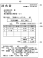
図4は、本実施形態における帳票画像400を示す図である。図5は、帳票画像400から項目情報抽出部306が抽出した検出結果501を示す図である。検出結果501は、複数の項目情報(図5における各行)を有する。さらに項目情報は、項目種類、順位、項目値、複数の項目名、正規形、及び項目値及び項目名毎に不図示の領域情報(領域の頂点座標)を有する。図4における領域401~408は、それぞれ図5におけるNo.1~8の項目値に対応する領域である。同様に領域402a、403a、404a~b、405a~b、406a~b、407a、408aは、No.2~6の各項目名に対応する領域である。またNo.7の項目名2は領域405bに対応し、No.8の項目名2は領域406bに対応する。
[Item detection results]
FIG. 4 is a diagram showing a
項目種類は、抽出された項目情報の種類を表す。検出結果501では「発行日」項目、「請求金額」項目、「電話番号」項目の3種類が検出されている。順位は、該項目情報が同種の項目種類の中で正しく該項目種類である確率の高さに基づき決まる。項目値は、該項目情報が表す項目値であり、帳票画像に含まれる文字列である。項目名は、項目種類に対応する文字列である。例えば検出結果501の「請求金額」項目に対応する項目名として「合計金額」、「合計」、「価格」が検出されている。正規形は、項目種類毎に決められた書式に項目値を適用することで正規化された文字列である。例えば「発行日」項目は「YYYYMMDD」の書式を正規形とし、検出結果501におけるNo.1では「2019年3月8日」が「20190308」に変換された文字列を正規形とする。同様に、「請求金額」項目では「小数点以下2桁の実数」を正規形として変換され、「電話番号」項目は「数字のみで構成される文字列」を正規形として変換される。これにより、帳票毎の項目値の表記の揺れを吸収する。
The item type represents the type of extracted item information. In the
[処理フロー]
次に、本実施形態の処理フローについて、図6のフローチャートを用いて説明する。
[Processing flow]
Next, the processing flow of this embodiment will be explained using the flowchart of FIG.
フローチャートで示される一連の処理は、データ入力支援装置100の制御部101がROM102またはHDD104に格納されているプログラムを読み出し、RAM103に展開して実行することにより行われる。あるいはまた、フローチャートにおけるステップの一部または全部の機能をASICや電子回路等のハードウェアで実現してもよい。フローチャートの説明における記号「S」は、当該フローチャートにおける「ステップ」を意味する。その他のフローチャートについても同様である。
The series of processes shown in the flowchart is performed by the
まず、S601で、制御部301は、RAM103またはHDD104に記憶された帳票画像400を取得する。
First, in S601, the
次に、S602で、文字認識部305は、帳票画像400を対象に文字認識処理を行う。これにより帳票画像400中の各文字列領域及び文字種が認識結果として得られる。
Next, in S602, the
次に、S603で、項目情報抽出部306は、文字認識結果に基づき、帳票画像400から項目情報を抽出する。これにより検出結果501が得られる。
Next, in S603, the item
次に、S604で、表示部302は、帳票画像400及び検出結果501をユーザに提示し、該検出結果を確認及び修正するための確認画面を生成し表示する。該処理については図7以降を用いて後述する。
Next, in S604, the
次に、S605で、入力部303は、ユーザ操作を取得する。ここでユーザは検出結果501の確認及び修正を行う。ユーザの入力内容に基づき、確認及び修正が終了したらS607に遷移し、そうでなければS606に遷移し確認画面を更新してS605に戻り、再度ユーザ入力の受付を行う。
Next, in S605, the
最後にS607で、制御部301は、ユーザによる確認及び修正が完了した項目情報を不図示の外部システムに送信し、処理を終了する。
Finally, in S607, the
[確認画面]
図7は、上記S604で生成される確認画面700を示す図である。確認画面700はユーザに対して検出結果501の内容を提示する。ユーザは、該画面で項目値が正しい領域から検出されているか、また正しい値が抽出されているかの確認を行い、誤りがあればその修正を行う。確認画面700は、俯瞰画像701、項目種類テキスト702a~c、項目値テキスト703a~c、項目画像704a~c、下位候補表示ボタン705a、705c、終了ボタン710を含む。項目画像704bは、さらに項目画像704ba、704bbを有する。
[confirmation screen]
FIG. 7 is a diagram showing a
俯瞰画像701は、帳票画像400に対して、検出結果501の順位1の各項目情報(No.1、No.3、No.5)に対応する領域401、403、403a、405、405a、405bをハイライト表示した画像である。項目値に関する領域401、403、405と、項目名に関する領域403a、405a、405bとが、それぞれ区別できるようにハイライト表示される。ユーザは俯瞰画像701上でスワイプ操作やピンチイン・ピンチアウト操作を行うことで、俯瞰画像701の表示位置や表示倍率の変更が可能である。
The bird's-
項目種類テキスト702a~cは、図6におけるS607で外部システムに送信される項目種類の名称を表示する。確認画面700では、項目種類テキスト702aに「発行日」、項目種類テキスト702bに「請求金額」、項目種類テキスト702cに「電話番号」が表示されている。
The item type texts 702a to 702c display the names of the item types sent to the external system in S607 in FIG. On the
項目値テキスト703a~cは、俯瞰画像701にハイライト表示された領域に対応する項目値が表示されるテキストエリアである。各テキストエリアはユーザ入力が可能であり、ユーザは、文字認識結果に誤りがある場合にはここで修正を行う。
項目画像704a~cは、俯瞰画像701にハイライト表示された領域に対応する項目名領域および項目値領域から作成される画像である。項目画像の作成方法については、図9~12を用いて後述する。各項目画像は上記S605にてユーザによる選択が可能である。項目画像が選択されると、該項目画像に対応する項目情報から項目値テキストが取得され表示される。さらに上記項目情報から項目名領域及び項目値領域が取得され、俯瞰画像701が該領域の位置をハイライトする表示に更新される。俯瞰画像701の更新に関する詳細は図13を用いて後述する。
Item images 704a to 704c are images created from the item name area and item value area corresponding to the area highlighted in the bird's-
下位候補表示ボタン705a、705cは、それぞれ対応する項目種類の下位候補を表示するためのボタンである。下位候補表示ボタン705aは項目種類「発行日」に対応し、下位候補表示ボタン705cは項目種類「電話番号」に対応する。下位候補表示ボタン705c押下時の動作については図8を用いて後述する。
The lower
終了ボタン710は、確認画面700を終了するためのボタンである。確認画面700による検出結果501の結果の確認及び修正が完了した後、ユーザは該ボタンを押下し確認を終了する。
The
図8は、下位候補表示ボタン705cを押下して表示される項目種類「電話番号」に対応する項目情報を表す図である。確認画面700で下位候補表示ボタン705cを押下すると、検出結果501において項目種類「電話番号」の項目情報が全て表示される。部分画像704ca~704cdは、検出結果501におけるNo.5~8の項目情報に対応する項目名領域、及び項目値領域を含む画像である。これらの画像は図7の項目画像704a~cと同様に各々選択可能であり、選択に応じて確認画面700は更新される。なお、下位候補表示ボタン705aを押下すると、項目種類「電話番号」の場合と同様に、項目種類が「発行日」である項目情報の部分画像が全て表示される。
FIG. 8 is a diagram showing item information corresponding to the item type "telephone number" displayed by pressing the lower
[項目画像の表示]
次に、図9のフローチャートを用いて、上記項目画像を表示する処理フローについて説明する。なお、ここでは検出結果501を対象として、図7の各項目画像704a~c、及び図8の部分画像704ca~cdを表示するフローを説明する。
[Show item image]
Next, a process flow for displaying the item images will be described with reference to the flowchart in Fig. 9. Note that, in this example, a flow for displaying each of the item images 704a to 704c in Fig. 7 and the partial images 704ca to 704cd in Fig. 8 will be described with reference to the
S901からS906までの処理は、項目種類毎(「発行日」、「請求金額」、「電話番号」)に実施される。 The processes from S901 to S906 are performed for each item type ("issue date", "billed amount", and "telephone number").
まずS902~S904において、表示部302は、項目情報毎に項目画像を作成する。S903における項目画像作成の処理フローは図10を用いて後述する。例えば項目種類「請求金額」については、図7に示すように、項目情報No.3の項目画像704ba及びNo.4の項目画像704bbが作成される。
First, in S902 to S904, the
次にS905において、表示部302は、作成された同種の項目画像に対して、正規形が同じ候補をグループ化する。項目種類「請求金額」については、No.3及びNo.4の正規形が一致するためグループ化され、項目画像704bが作成される。
Next, in S905, the
上記処理の終了後、S907において、表示部302は、作成された項目画像を確認画面700上に表示し、本処理フローは終了する。
After the above process is completed, in S907, the
図10は、上記S903における項目画像作成の処理フローを示す図である。ここでは検出結果501における項目情報No.5を入力した場合を例に説明する。
Figure 10 shows the process flow for creating an item image in S903 above. Here, we will explain an example in which item information No. 5 in the
まずS1001からS1004の処理がi=1~Nまで繰り返される。ここでNは、入力される項目情報と同種の項目情報が有する最大項目名数とする。No.5が入力の場合、項目種類は「電話番号」であり、その最大項目名数は2となる。 First, the processes from S1001 to S1004 are repeated until i=1 to N. Here, N is the maximum number of item names that item information of the same type as the input item information has. No. If 5 is input, the item type is "telephone number" and the maximum number of item names is 2.
S1002では、表示部302は、項目名のi個の集合Vを準備する。ここで集合V=[v_1,・・・,v_M]とし、集合Vの要素v_j=[項目名1(j),・・・,項目名i(j)]と定義する。なお、Mは同項目種類における項目情報数、項目名i(j)は順位jの項目名iとする。項目種類「電話番号」においてはM=4である。また初回のループではi=1であり、V=[[TEL],[TEL],[FAX],[FAX]]となる。
In S1002, the
S1003では、表示部302は、Vの要素に重複があるかどうか判定する。本実施形態では、重複判定は「2つの要素v_a、v_bについて「x=1~i全てで「v_axとv_bxに包含関係がある」」なら真」を返す関数により行う。該関数によれば、Vの要素間で重複がある([TEL]及び[FAX]がそれぞれ重複する)ので、S1004に遷移する。
In S1003, the
S1004ではiをインクリメントしS1001へ遷移する。以上の処理をi=Nまで繰り返す。 In S1004, i is incremented and the process moves to S1001. The above process is repeated until i=N.
No.5を入力としたi=2のループでは、S1002における集合Vは[[TEL,本社],[TEL,営業所],[FAX,本社],[FAX,営業所]]となる。該集合Vに対してS1003では重複はないと判定される。具体的には、v_1=[TEL,本社]とv_2=[TEL,営業所]を比較すると、v_11=「TEL」とv_21=「TEL」は包含関係がある(完全一致する)が、v_12=「本社」とv_22=「営業所」は包含関係がない。したがって、v_1とv_2は重複しない。同様にv_1、v_2、v_3、v_4間の全ての組み合わせについて重複がないため、S1003からループを抜けてS1005へ遷移する。
No. In the loop with i=2 with
S1005では、表示部302は、項目値領域及び項目名1~i領域を有する部分画像を作成し、これを項目画像として取得する。項目情報No.5においてはi=2であり、項目値、項目名1、項目名2を含む部分画像が作成され、これにより項目画像704cが取得される。S1005の処理の詳細は、図11を用いて後述する。
In S1005, the
図10に示す処理フローでは、項目情報間で区別可能な粒度の項目名のみを含む項目画像を作成する。例えば検出結果501の項目種類「電話番号」では項目名1及び2が含まれるが、仮にNo.6及びNo.8が検出されず、No.5及びNo.7のみが検出された場合、項目画像に含まれるのは項目値領域及び項目名1領域のみとなる。
In the process flow shown in FIG. 10, an item image is created that includes only item names with a granularity that allows item information to be distinguished. For example, the item type "telephone number" in the
図11は、上記S1005における部分画像作成の処理フローを説明する図である。 FIG. 11 is a diagram illustrating the processing flow of partial image creation in S1005 above.
まず、S1101において、表示部302は、RAM103またはHDD104に記憶された帳票画像を取得する。
First, in S1101, the
次に、S1102において、表示部302は、項目値領域を取得しこれをRとする。項目値領域Rは、帳票画像中の矩形領域であり、矩形の4頂点の座標を有する。
Next, in S1102, the
次に、S1103からS1110までの処理をn回繰り返す。ここでnは、入力される項目情報が有する項目名数である。 Next, the process from S1103 to S1110 is repeated n times, where n is the number of item names contained in the input item information.
S1104では、表示部302は、項目名iの領域を取得しこれをSとする。
In S1104, the
次にS1105において、表示部302は、領域Rと領域S間のy方向距離distY(R,S)を取得し、これが所定の値Tyより大であるか否かの判定をする。distY(R,S)は、両領域をy軸上に射影した際に重複があれば距離0とし、重複が無ければ両領域間の距離を得る関数とする。Tyは例えば10ピクセルとする。
Next, in S1105, the
S1105においてy方向距離がTyより大である場合、S1106に遷移し、領域Rと領域S間の距離を小さくするように画像に対して圧縮処理を行いS1107へ遷移する。該処理の詳細は図12で具体例を用いて説明する。S1105において距離がTy以下である場合は、S1106はスキップされ、S1107へ遷移する。 If the distance in the y direction is greater than Ty in S1105, the process moves to S1106, where compression processing is performed on the image to reduce the distance between the region R and the area S, and the process moves to S1107. The details of this process will be explained using a specific example in FIG. If the distance is less than or equal to Ty in S1105, S1106 is skipped and the process moves to S1107.
S1107及びS1108は、上記S1105及びS1106と同様の処理をx方向に対して適用する。Txは例えば20ピクセルとする。 In S1107 and S1108, the same processing as in S1105 and S1106 described above is applied in the x direction. For example, Tx is 20 pixels.
S1109では、表示部302は、項目値領域Rを、画像圧縮後の座標系における上記領域Rと上記領域Sの外接矩形として更新する。
In S1109, the
S1110では、表示部302は、iをインクリメントし、S1104へ遷移する。
In S1110, the
最後に、S1111で表示部302は領域Rをトリミングし、新たな画像を作成し、部分画像として出力し終了する。
Finally, in S1111, the
続いて、図12を用いて図11に示した部分画像作成フローの具体的な動作を説明する。図12では次の項目情報の入力を想定している。項目種類「請求金額」、項目値「11,286」、項目名1「合計」、項目名2「価格」である。
Next, the specific operation of the partial image creation flow shown in FIG. 11 will be explained using FIG. 12. In FIG. 12, the following item information is assumed to be input. These are the item type “Billed Amount”, the item value “11,286”, the
図12(a)は、説明のため帳票画像の一部をトリミングした画像を示す。領域1201は項目値「11,286」に対応する領域であり、領域1202は項目名1「合計」に対応する領域であり、領域1203は項目名2「価格」に対応する領域である。図12(b)では、領域1201の左辺の延長線上を線1201L、領域1202の右辺の延長線上を線1202Rで示し、同様に領域1203についても左右の辺の延長線を線1203L、Rで表している。
FIG. 12A shows an image obtained by cropping a part of the form image for explanation.
まず上記S1102において表示部302は領域R=項目名領域を取得する。図12(a)において、領域Rは領域1201である。次にS1104で表示部302は領域S=項目名1領域を取得する。図12(a)において領域Sは領域1202である。次にS1105において、表示部302は領域Rと領域Sのy方向距離を取得し、閾値Tyより大であるか判定する。領域1201と領域1202は、y軸上で重複があるためy方向距離は0であり、S1106はスキップされる。次にS1107において、表示部302は両領域のx方向距離を取得し、Txより大であるか判定する。x方向距離は図12(b)における線1201Lと線1202R間の距離である。ここでは該距離がTxより大であるものとし、S1108へ遷移し、x方向圧縮処理を適用する。x方向圧縮処理は、両領域間の画像を除去することで実現する。ただし、除去される領域に他の項目名領域があれば、該領域は残すように除去する。ここでは除去対象領域である線1202Rと線1201Lの間に領域1203が含まれるため、線1202Rと線1203Lの間、及び線1203Rと線1201Lの間が除去される。これにより作成される画像を図12(c)に示す。なお、ここでは領域間の画像を除去する際に、各領域の近傍に一定サイズの余白を持たせている。続いてS1109で、新たに作成された画像内の上記領域Rと領域Sの外接矩形領域を新たに領域Rとして更新する。図12(c)において、更新後の領域Rは領域1204となる。
First, in S1102 described above, the
上記処理の終了後、i=2としてS1104から2回目の処理を行う。2回目のS1104では、領域Sは項目名2の領域1205となる。続いてS1105でy方向距離を判定する。y方向距離は図12(d)における線1204Tと線1205B間の距離となる。該距離は閾値Tyより大きいものとし、S1106で表示部302はy方向圧縮処理を行う。該処理では上記x方向圧縮処理と同様の処理をy方向に対して行う。領域1204と領域1205の間には他の項目名領域が無いため、両領域間を除去すればよい。S1107では同様にx方向距離を判定するが、領域1204と領域1205はx軸上で重複し、距離0であるためx方向圧縮処理は行われない。
After the above process is completed, the second process is performed from S1104 with i=2. In the second S1104, the area S becomes the
以上の処理により作成される部分画像を図12(e)に示す。なお、図12(c)、(e)では、圧縮されたことをユーザに明示するためのマーカー1206~1208を示す。該マーカーにより画像が除去された領域がユーザにわかりやすくなる。
A partial image created by the above processing is shown in FIG. 12(e). Note that FIGS. 12(c) and 12(e)
[項目画像選択時の俯瞰画像更新]
確認画面700において、各項目画像はユーザが選択することが可能である。項目画像が選択されると、俯瞰画像701は該項目画像に対応する項目名領域、及び項目値領域がハイライト表示された画像に更新される。図13は俯瞰画像701の更新処理に関する処理フローである。
[Overhead image update when selecting item image]
On the
まずS1301において、表示部302は帳票画像を取得する。
First, in S1301, the
次にS1302において、表示部302はユーザによって選択された項目画像に対応する項目値領域、及び項目名領域を取得する。
Next, in S1302, the
続いて、S1303において、表示部302は取得された上記領域の外接矩形を取得する。
Subsequently, in S1303, the
続いて、S1304において、表示部302は点Pを上記外接矩形の中心座標として取得する。
Subsequently, in S1304, the
続いて、S1305において、表示部302は倍率Scaleを[表示文字サイズ]/[最小文字高さ]として計算する。[表示文字サイズ]は事前に設定されたパラメータであり、[最小文字高さ]はS1302で取得した各領域の文字高さの最小値である。これにより、帳票画像をScale倍すると各領域の高さは[表示文字サイズ]ピクセル以上となる。
Subsequently, in S1305, the
続いて、S1306において、表示部302は[外接矩形サイズ×Scale]が俯瞰画像表示エリアのサイズよりも大きいか否か判定する。ここで外接矩形サイズとはS1303で取得された外接矩形の幅及び高さであり、俯瞰画像表示エリアとは確認画面700において俯瞰画像701を表示する領域の幅及び高さとする。幅、あるいは高さのいずれかが条件を満たせばS1306は真としてS1307に遷移し、偽であればS1308に遷移する。
Next, in S1306, the
上記S1306が真の場合、S1307で表示部302は、上記S1304で取得した点Pを項目名領域の中心座標に更新し、さらに上記S1305で取得したScaleを[表示文字サイズ]/[項目値領域高さ]に更新する。
If S1306 above is true, in S1307 the
続いてS1308において、表示部302は、帳票画像をScale倍した画像を、点Pを中心として上記俯瞰画像表示エリアのサイズにトリミングして、トリミング画像を作成する。仮にS1306が偽であった場合、上記トリミング画像には上記S1302で取得した全領域が含まれ、その中心が画像中心となる。一方、S1306が真であった場合、上記トリミング画像は項目名領域を中心とした画像となる。
Subsequently, in S1308, the
続いて、S1309において、表示部302は上記トリミング画像において、上記領域をハイライト表示する。
Subsequently, in S1309, the
最後に、S1310において、表示部302は上記トリミング画像を俯瞰画像表示エリアに表示し、処理フローを終了する。
Finally, in S1310, the
なお、図13には不図示であるが、S1307の次に、さらにScale×[項目名領域の幅]が上記俯瞰画像表示エリアの幅よりも大きければ、項目名領域が該表示エリアの幅以下になるようにScaleを調整してもよい。 Although not shown in FIG. 13, after S1307, if Scale x [width of item name area] is larger than the width of the bird's-eye view image display area, the item name area is smaller than or equal to the width of the display area. You may adjust the Scale so that
図14は、確認画面700において項目画像704baが選択されて表示される画面を表した図である。ここでは、項目画像704baが選択されたことをハイライト表示する枠1401が描画され、図13に示した処理フローで更新された俯瞰画像1402が表示されている。俯瞰画像1402は選択された項目画像に対応する項目値領域1403a及び項目名領域1403bが所定のサイズで表示される倍率に拡大され、また両領域がハイライト表示されることで各領域が視認しやすくなっている。
Figure 14 shows the screen on which item image 704ba is selected and displayed on
[俯瞰画像外の項目領域表示]
前述のように確認画面700においてユーザ操作を行うことで、俯瞰画像701の表示画像位置、あるいは表示倍率を変更することが可能である。この際、図14に示した俯瞰画像1402に対して同操作を行うと、ハイライト表示された選択中の項目名領域及び項目値領域が画像外に出てしまう場合がある。このように、選択された項目名領域あるいは項目値領域が画像外にある場合には、該領域を俯瞰画像上でハイライト表示する。
[Display of item area outside overhead image]
As described above, it is possible to change the display image position or display magnification of the
図15は、確認画面700において項目画像704bbが選択された状態で、俯瞰画像の表示領域が変更された状態を説明する図である。帳票画像400に対して領域1501が俯瞰画像の領域として指定され、該領域が切り出されて俯瞰画像1503が作成される。俯瞰画像1503において、選択済みの項目画像704bbに対応する領域404及び領域404aは領域1501に内包されるため、図14の領域1403a及び領域1403bと同様に項目値領域1504及び項目名領域1505としてハイライト表示される。一方で領域404bは領域1501の外側にある。そこで、領域1501の中心と領域404bの中心とを結ぶ直線と、領域1501の交点1502を求め、俯瞰画像1503上で交点1502に対応する点1507上(すなわち、俯瞰画像1503の枠上)に、ポップアップ画像1506を重畳する。ポップアップ画像1506は、領域404bを切り出した画像から作成する。
FIG. 15 is a diagram illustrating a state in which the display area of the bird's-eye view image is changed while the item image 704bb is selected on the
以上説明したように、本実施形態によると、帳票画像から抽出された項目値に対応する項目名を合わせて表示することにより、抽出された項目値の確認作業が容易になる。 As described above, according to this embodiment, the item names corresponding to the item values extracted from the form image are also displayed, making it easier to check the extracted item values.
<その他の実施形態>
本発明は、上述の実施形態の1以上の機能を実現するプログラムを、ネットワーク又は記憶媒体を介してシステム又は装置に供給し、そのシステム又は装置のコンピュータにおける1つ以上のプロセッサーがプログラムを読出し実行する処理でも実現可能である。また、1以上の機能を実現する回路(例えば、ASIC)によっても実現可能である。
<Other embodiments>
The present invention provides a system or device with a program that implements one or more of the functions of the embodiments described above via a network or a storage medium, and one or more processors in the computer of the system or device reads and executes the program. This can also be achieved by processing. It can also be realized by a circuit (for example, ASIC) that realizes one or more functions.
Claims (10)
確認画面を表示する表示手段と
を有し、
前記確認画面は、
前記画像の全体または一部を表示する第一の表示領域と、
所定項目に対応付けて、前記複数の文字列の中から1つの文字列を表示する第二の表示領域と、
前記所定項目に対応付けて、前記画像の部分画像であって、前記所定項目に対応する文字列の項目名を含む複数の部分画像を表示する第三の表示領域と、を含み、
前記第二の表示領域において前記所定項目に対応付けて前記1つの文字列を表示するために、前記第三の表示領域において、前記所定項目に対応する文字列の項目名を含む前記複数の部分画像の中から1つの部分画像の選択をユーザから受け付ける、
ことを特徴とするデータ入力支援装置。 an acquisition means for acquiring a plurality of character strings obtained by character recognition processing on an image ;
and display means for displaying a confirmation screen,
The confirmation screen is
a first display area that displays all or part of the image ;
a second display area that displays one character string from the plurality of character strings in association with a predetermined item ;
a third display area that displays a plurality of partial images of the image that are associated with the predetermined item and include item names of character strings corresponding to the predetermined item ;
In order to display the one character string in association with the predetermined item in the second display area, in the third display area, the plurality of portions including the item name of the character string corresponding to the predetermined item. Accepting the selection of one partial image from the image from the user,
A data input support device characterized by:
前記画像の全体または一部を表示する第一の表示領域と、
所定項目に対応付けて、前記複数の文字列の中から1つの文字列を表示する第二の表示領域と、
前記所定項目に対応付けて、前記画像の部分画像であって、前記所定項目に対応する文字列の項目名を含む複数の部分画像を表示する第三の表示領域と、を含み、
前記第二の表示領域において前記所定項目に対応付けて前記1つの文字列を表示するために、前記第三の表示領域において、前記所定項目に対応する文字列の項目名を含む前記複数の部分画像の中から1つの部分画像の選択をユーザから受け付ける、
ことを特徴とする表示装置。 A display device that displays a confirmation screen of a plurality of character strings obtained by character recognition processing on an image , the confirmation screen comprising:
a first display area that displays all or part of the image ;
a second display area that displays one character string from the plurality of character strings in association with a predetermined item ;
a third display area that displays a plurality of partial images of the image that are associated with the predetermined item and include item names of character strings corresponding to the predetermined item ;
In order to display the one character string in association with the predetermined item in the second display area, in the third display area, the plurality of portions including the item name of the character string corresponding to the predetermined item. Accepting the selection of one partial image from the image from the user,
A display device characterized by:
確認画面を表示する表示工程と
を含み、
前記確認画面は、
前記画像の全体または一部を表示する第一の表示領域と、
所定項目に対応付けて、前記複数の文字列の中から1つの文字列を表示する第二の表示領域と、
前記所定項目に対応付けて、前記画像の部分画像であって、前記所定項目に対応する文字列の項目名を含む複数の部分画像を表示する第三の表示領域と、を含み、
前記第二の表示領域において前記所定項目に対応付けて前記1つの文字列を表示するために、前記第三の表示領域において、前記所定項目に対応する文字列の項目名を含む前記複数の部分画像の中から1つの部分画像の選択をユーザから受け付ける、
ことを特徴とするデータ入力支援方法。 An acquisition step of acquiring a plurality of character strings obtained by character recognition processing on an image ;
A display step of displaying a confirmation screen;
The confirmation screen is
a first display area for displaying the entire or a part of the image ;
a second display area for displaying one character string from among the plurality of character strings in association with a predetermined item ;
a third display area for displaying a plurality of partial images of the image, the partial images including item names of character strings corresponding to the predetermined items, in association with the predetermined items;
receiving, from a user, a selection of one partial image from among the plurality of partial images including an item name of a character string corresponding to the predetermined item in the third display area, so as to display the one character string in the second display area in association with the predetermined item;
A data entry support method comprising:
Priority Applications (1)
| Application Number | Priority Date | Filing Date | Title |
|---|---|---|---|
| JP2020025035A JP7458816B2 (en) | 2020-02-18 | 2020-02-18 | Data input support device, data input support method, display device, and program |
Applications Claiming Priority (1)
| Application Number | Priority Date | Filing Date | Title |
|---|---|---|---|
| JP2020025035A JP7458816B2 (en) | 2020-02-18 | 2020-02-18 | Data input support device, data input support method, display device, and program |
Publications (3)
| Publication Number | Publication Date |
|---|---|
| JP2021131593A JP2021131593A (en) | 2021-09-09 |
| JP2021131593A5 JP2021131593A5 (en) | 2023-03-01 |
| JP7458816B2 true JP7458816B2 (en) | 2024-04-01 |
Family
ID=77550935
Family Applications (1)
| Application Number | Title | Priority Date | Filing Date |
|---|---|---|---|
| JP2020025035A Active JP7458816B2 (en) | 2020-02-18 | 2020-02-18 | Data input support device, data input support method, display device, and program |
Country Status (1)
| Country | Link |
|---|---|
| JP (1) | JP7458816B2 (en) |
Citations (8)
| Publication number | Priority date | Publication date | Assignee | Title |
|---|---|---|---|---|
| JP2006209599A (en) | 2005-01-31 | 2006-08-10 | Casio Hitachi Mobile Communications Co Ltd | Portable terminal, character reading method, and character reading program |
| JP2008158988A (en) | 2006-12-26 | 2008-07-10 | Canon It Solutions Inc | Information processor and control method therefor, program, and computer-readable storage medium |
| JP2009122722A (en) | 2007-11-09 | 2009-06-04 | Fujitsu Ltd | Document recognizing program, document recognizing apparatus and document recognizing method |
| JP2012133507A (en) | 2010-12-21 | 2012-07-12 | Fujitsu Marketing Ltd | Receipt data collation support apparatus and receipt data collation support program |
| JP2016126356A (en) | 2014-12-26 | 2016-07-11 | ブラザー工業株式会社 | Image processing program, image processing method, and image processing apparatus |
| JP2016143284A (en) | 2015-02-03 | 2016-08-08 | 沖電気工業株式会社 | Information processing apparatus, information processing system, information processing method, and program |
| JP2019040467A (en) | 2017-08-25 | 2019-03-14 | キヤノン株式会社 | Information processing apparatus and control method therefor |
| JP2020017149A (en) | 2018-07-26 | 2020-01-30 | 株式会社 ハンモック | Information processing device and information processing method |
-
2020
- 2020-02-18 JP JP2020025035A patent/JP7458816B2/en active Active
Patent Citations (8)
| Publication number | Priority date | Publication date | Assignee | Title |
|---|---|---|---|---|
| JP2006209599A (en) | 2005-01-31 | 2006-08-10 | Casio Hitachi Mobile Communications Co Ltd | Portable terminal, character reading method, and character reading program |
| JP2008158988A (en) | 2006-12-26 | 2008-07-10 | Canon It Solutions Inc | Information processor and control method therefor, program, and computer-readable storage medium |
| JP2009122722A (en) | 2007-11-09 | 2009-06-04 | Fujitsu Ltd | Document recognizing program, document recognizing apparatus and document recognizing method |
| JP2012133507A (en) | 2010-12-21 | 2012-07-12 | Fujitsu Marketing Ltd | Receipt data collation support apparatus and receipt data collation support program |
| JP2016126356A (en) | 2014-12-26 | 2016-07-11 | ブラザー工業株式会社 | Image processing program, image processing method, and image processing apparatus |
| JP2016143284A (en) | 2015-02-03 | 2016-08-08 | 沖電気工業株式会社 | Information processing apparatus, information processing system, information processing method, and program |
| JP2019040467A (en) | 2017-08-25 | 2019-03-14 | キヤノン株式会社 | Information processing apparatus and control method therefor |
| JP2020017149A (en) | 2018-07-26 | 2020-01-30 | 株式会社 ハンモック | Information processing device and information processing method |
Non-Patent Citations (1)
| Title |
|---|
| BitMap Family,個人でも買えるエプソンの名刺カードリーダー,PC WAVE 1994-11,日本,株式会社電波実験社,1994年11月01日,第2巻 第11号 ,P.113-117 |
Also Published As
| Publication number | Publication date |
|---|---|
| JP2021131593A (en) | 2021-09-09 |
Similar Documents
| Publication | Publication Date | Title |
|---|---|---|
| JP5326859B2 (en) | Image processing device | |
| JP5439455B2 (en) | Electronic comic editing apparatus, method and program | |
| JP5211193B2 (en) | Translation display device | |
| KR100570224B1 (en) | Form definition data creation method and form handling machines | |
| WO2013058397A1 (en) | Digital comic editing device and method therefor | |
| JP2016224599A (en) | Guide file creation program | |
| JP5339308B2 (en) | Information processing apparatus, information processing method, program, and recording medium. | |
| US8355577B2 (en) | Image processing apparatus and method | |
| JP7035656B2 (en) | Information processing equipment and programs | |
| JP7458816B2 (en) | Data input support device, data input support method, display device, and program | |
| JP2022162908A (en) | Image processing apparatus, image processing method, and program | |
| JP2006277001A (en) | Input image displaying method, and input image displaying program | |
| JPH08166865A (en) | Method and device for screen generation | |
| US11588945B2 (en) | Data input support apparatus that displays a window with an item value display area, an overview image display area, and an enlarged image display area | |
| JP2021144469A (en) | Data input support system, data input support method, and program | |
| JP2022010994A (en) | Data input assistance device, data input assistance method and program | |
| CN111492338B (en) | Integrated document editor | |
| JP4712629B2 (en) | Equipment specification input device | |
| KR102538105B1 (en) | A system, a device and a method for entering patience's answers for medical questionnaire | |
| JPH0728801A (en) | Image data processing method and device therefor | |
| JP5767574B2 (en) | Image processing apparatus and image processing system | |
| JP3637771B2 (en) | Document editing output device | |
| JPH103516A (en) | Method and device for processing information | |
| JP3761923B2 (en) | Image processing apparatus and method | |
| JPH0973515A (en) | Character recognition device |
Legal Events
| Date | Code | Title | Description |
|---|---|---|---|
| A521 | Request for written amendment filed |
Free format text: JAPANESE INTERMEDIATE CODE: A523 Effective date: 20230220 |
|
| A621 | Written request for application examination |
Free format text: JAPANESE INTERMEDIATE CODE: A621 Effective date: 20230220 |
|
| A977 | Report on retrieval |
Free format text: JAPANESE INTERMEDIATE CODE: A971007 Effective date: 20231204 |
|
| A131 | Notification of reasons for refusal |
Free format text: JAPANESE INTERMEDIATE CODE: A131 Effective date: 20231212 |
|
| A521 | Request for written amendment filed |
Free format text: JAPANESE INTERMEDIATE CODE: A523 Effective date: 20240213 |
|
| TRDD | Decision of grant or rejection written | ||
| A01 | Written decision to grant a patent or to grant a registration (utility model) |
Free format text: JAPANESE INTERMEDIATE CODE: A01 Effective date: 20240220 |
|
| A61 | First payment of annual fees (during grant procedure) |
Free format text: JAPANESE INTERMEDIATE CODE: A61 Effective date: 20240319 |
|
| R151 | Written notification of patent or utility model registration |
Ref document number: 7458816 Country of ref document: JP Free format text: JAPANESE INTERMEDIATE CODE: R151 |