JP7454482B2 - vehicle cleaning system - Google Patents
vehicle cleaning system Download PDFInfo
- Publication number
- JP7454482B2 JP7454482B2 JP2020172132A JP2020172132A JP7454482B2 JP 7454482 B2 JP7454482 B2 JP 7454482B2 JP 2020172132 A JP2020172132 A JP 2020172132A JP 2020172132 A JP2020172132 A JP 2020172132A JP 7454482 B2 JP7454482 B2 JP 7454482B2
- Authority
- JP
- Japan
- Prior art keywords
- vehicle
- sensor
- cleaning
- cleaning unit
- state
- Prior art date
- Legal status (The legal status is an assumption and is not a legal conclusion. Google has not performed a legal analysis and makes no representation as to the accuracy of the status listed.)
- Active
Links
- 238000004140 cleaning Methods 0.000 title claims description 266
- 238000005406 washing Methods 0.000 claims description 92
- 239000007788 liquid Substances 0.000 claims description 71
- 238000002347 injection Methods 0.000 claims description 27
- 239000007924 injection Substances 0.000 claims description 27
- 238000012545 processing Methods 0.000 claims description 22
- 238000005507 spraying Methods 0.000 claims description 20
- XLYOFNOQVPJJNP-UHFFFAOYSA-N water Substances O XLYOFNOQVPJJNP-UHFFFAOYSA-N 0.000 description 44
- 238000001514 detection method Methods 0.000 description 34
- 238000000034 method Methods 0.000 description 13
- 230000008569 process Effects 0.000 description 11
- 230000007246 mechanism Effects 0.000 description 10
- 239000000243 solution Substances 0.000 description 9
- 238000010586 diagram Methods 0.000 description 5
- 239000012530 fluid Substances 0.000 description 5
- 238000009434 installation Methods 0.000 description 5
- 230000004044 response Effects 0.000 description 4
- 239000007921 spray Substances 0.000 description 4
- 238000013459 approach Methods 0.000 description 3
- 239000003595 mist Substances 0.000 description 3
- 230000000903 blocking effect Effects 0.000 description 2
- 230000002159 abnormal effect Effects 0.000 description 1
- 230000005856 abnormality Effects 0.000 description 1
- 230000002528 anti-freeze Effects 0.000 description 1
- 230000008901 benefit Effects 0.000 description 1
- 230000005540 biological transmission Effects 0.000 description 1
- 239000000470 constituent Substances 0.000 description 1
- 238000010438 heat treatment Methods 0.000 description 1
- 238000005259 measurement Methods 0.000 description 1
- 238000012986 modification Methods 0.000 description 1
- 230000004048 modification Effects 0.000 description 1
- 238000003672 processing method Methods 0.000 description 1
Images


Description
本発明は、車両洗浄システムに関する。 TECHNICAL FIELD The present invention relates to a vehicle cleaning system.
特許第3166002号(以下、特許文献1という。)には、大型自動車および小型自動車の洗浄が可能な洗浄装置が記載されている。ここでは、洗浄装置は、洗浄水噴射機構と、進入側センサポールと、退出側センサポールとで構成されている。また、洗車装置は、進入側センサポールが車体を検知すると洗浄水噴射機構が噴射を開始し、退出側センサポールが車体を検知しなくなると、洗浄水噴射機構が噴射を停止する。 Japanese Patent No. 3166002 (hereinafter referred to as Patent Document 1) describes a washing device capable of washing large-sized automobiles and small-sized automobiles. Here, the cleaning device includes a cleaning water injection mechanism, an entrance-side sensor pole, and an exit-side sensor pole. Further, in the car wash device, when the entrance side sensor pole detects the vehicle body, the cleaning water injection mechanism starts spraying, and when the exit side sensor pole no longer detects the vehicle body, the cleaning water injection mechanism stops spraying.
特許文献1に記載のような車両洗浄システム(特許文献1の洗車装置を含む。以下同じ。)では、洗浄ユニット(洗浄水噴射機構)に対して車両を検知する進入側センサ(進入側センサポール)や退出側センサ(退出側センサポール)が離れている。例えば、進入側センサで車両を検知して洗浄ユニットで洗浄液(洗浄水を含む。)を噴射させる構成では、進入側センサで車両を検知してから、車両が洗浄ユニットに到達するまでの間は、洗浄が行われず、洗浄液が無駄に噴射されてしまう。また、例えば、退出側センサで車両を検知しなくなるまで洗浄ユニットで洗浄液を噴射させる構成では、車両が洗浄ユニットから離れてから、車両が退出側センサに到達するまでの間は、洗浄が行われず、洗浄液が無駄に噴射されてしまう。
In a vehicle washing system such as that described in Patent Document 1 (including the car washing device of
そこで、洗浄ユニットに対して進入側センサや退出側センサを近づけることも考えられる。しかしながら、洗浄ユニットに対して進入側センサや退出側センサが近くなると、これらセンサは、洗浄ユニットから噴射された洗浄液(霧、液滴、飛沫の状態を含む。)の影響を受け、車両がないにも関わらず、あるものとして誤検知してしまうおそれがある。例えば、誤検知により洗浄ユニットからの洗浄液の噴射が停止されず、洗浄液が無駄に噴射されてしまう。 Therefore, it is conceivable to bring the entrance side sensor and the exit side sensor closer to the cleaning unit. However, when the approach side sensor and the exit side sensor are close to the cleaning unit, these sensors are affected by the cleaning liquid (including mist, droplets, and splashes) sprayed from the cleaning unit, and when the vehicle is not present. Despite this, there is a risk that it may be falsely detected. For example, the spraying of the cleaning liquid from the cleaning unit is not stopped due to erroneous detection, and the cleaning liquid is wasted.
本発明の一目的は、洗浄液を節約することのできる技術を提供することにある。 One object of the present invention is to provide a technique that can save cleaning fluid.
(解決項1)
車両に対して洗浄液を噴射する処理機能を有する車両洗浄システムであって、
前記車両の車長方向に沿って設けられた洗浄ユニット、第1センサ、および第2センサを備え、
前記処理機能は、前記洗浄ユニットからの洗浄液の噴射を実行している最中に、前記第1センサまたは前記第2センサの少なくともいずれか一方がOFF状態からON状態となって継続した場合に、前記洗浄ユニットからの洗浄液の噴射を停止させる機能を有する、
ことを特徴とする車両洗浄システム。
(解決項2)
前記洗浄ユニットは、第1および第2噴射口と、前記第1噴出口を露出する開口を有する第1板と、前記第2噴出口を露出する開口を有する第2板と、を備え、
前記車両の車高方向において前記第1板より前記第2板が高く設けられ、
前記車両の車幅方向において前記第1板より前記第2板が奥に設けられ、
前記第1および第2センサが、前記車両の車高方向において前記第1板の寸法内の高さに設けられ、かつ前記車両の車幅方向において前記第2板より奥に設けられている、
解決項1記載の車両洗浄システム。
(解決項3)
前記車両の下部に対して洗浄液を噴射する処理機能を有する下部洗浄ユニットを備え、
前記下部洗浄ユニットは、前記第2センサより前記第1センサの近くに設けられており、
前記第1センサおよび前記第2センサがそれぞれ第1アームおよび第2アームを介して前記洗浄ユニットに取り付けられ、
前記第1アームが前記第2アームよりも長い、
解決項1または2記載の車両洗浄システム。
(解決項4)
前記車両の車長方向に沿って設けられた第3センサを備え、
前記第3センサ、前記洗浄ユニット、前記第1センサ、および前記第2センサは、この順に前記車両が通過するよう配置され、
前記処理機能は、前記洗浄ユニットからの洗浄液の噴射を実行している最中に、前記第3センサがON状態で、かつ前記第2センサがOFF状態からON状態となって継続した場合に、前記洗浄ユニットからの洗浄液の噴射を停止させる機能を有する、
解決項1~3のいずれか一項に記載の車両洗浄システム。
(解決項5)
前記処理機能は、前記洗浄ユニットからの洗浄液の噴射を停止させるタイミングを前記車両の種類によって設定する機能を有する、
解決項1~4のいずれか一項に記載の車両洗浄システム。
(Solution 1)
A vehicle cleaning system having a processing function of injecting a cleaning liquid to a vehicle,
comprising a cleaning unit, a first sensor, and a second sensor provided along the vehicle length direction of the vehicle,
The processing function is performed when at least one of the first sensor and the second sensor changes from an OFF state to an ON state and continues while spraying the cleaning liquid from the cleaning unit. having a function of stopping the injection of cleaning liquid from the cleaning unit;
A vehicle washing system characterized by:
(Solution item 2)
The cleaning unit includes first and second jet ports, a first plate having an opening exposing the first jet port, and a second plate having an opening exposing the second jet port,
The second plate is provided higher than the first plate in the vehicle height direction of the vehicle,
The second plate is provided further back than the first plate in the vehicle width direction of the vehicle,
The first and second sensors are provided at a height within the dimensions of the first plate in the vehicle height direction of the vehicle, and are provided deeper than the second plate in the vehicle width direction of the vehicle,
The vehicle washing system according to
(Solution 3)
comprising a lower part cleaning unit having a processing function of injecting a cleaning liquid to the lower part of the vehicle,
The lower cleaning unit is provided closer to the first sensor than the second sensor,
the first sensor and the second sensor are attached to the cleaning unit via a first arm and a second arm, respectively;
the first arm is longer than the second arm;
The vehicle washing system according to
(Solution 4)
comprising a third sensor provided along the vehicle length direction of the vehicle,
The third sensor, the cleaning unit, the first sensor, and the second sensor are arranged so that the vehicle passes in this order,
The processing function is performed when the third sensor is in the ON state and the second sensor continues from the OFF state to the ON state while the cleaning liquid is being sprayed from the cleaning unit. having a function of stopping the injection of cleaning liquid from the cleaning unit;
The vehicle cleaning system according to any one of
(Solution item 5)
The processing function has a function of setting a timing for stopping the injection of cleaning liquid from the cleaning unit depending on the type of the vehicle.
The vehicle cleaning system according to any one of
本発明の一効果は、洗浄液を節約することができる。 One advantage of the present invention is that cleaning fluid can be saved.
以下の本発明における実施形態では、必要な場合に複数のセクションなどに分けて説明するが、原則、それらはお互いに無関係ではなく、一方は他方の一部または全部の変形例、詳細などの関係にある。このため、全図において、同一の機能を有する部材には同一の符号を付し、その繰り返しの説明は省略する。また、構成要素の数(個数、数値、量、範囲などを含む)については、特に明示した場合や原理的に明らかに特定の数に限定される場合などを除き、その特定の数に限定されるものではなく、特定の数以上でも以下でも良い。また、構成要素などの形状に言及するときは、特に明示した場合および原理的に明らかにそうではないと考えられる場合などを除き、実質的にその形状などに近似または類似するものなどを含むものとする。 The following embodiments of the present invention will be explained in multiple sections if necessary, but in principle, they are not unrelated to each other, and one has a relationship with the other in terms of modifications, details, etc. of some or all of the other. It is in. Therefore, in all the figures, members having the same functions are designated by the same reference numerals, and repeated explanations thereof will be omitted. Furthermore, the number of constituent elements (including numbers, numerical values, amounts, ranges, etc.) shall not be limited to a specific number unless otherwise specified or in principle clearly limited to a specific number. It does not have to be a specific number, and may be more than or less than a certain number. Furthermore, when referring to the shape of a component, etc., it shall include anything that substantially approximates or resembles that shape, etc., unless specifically specified or if it is clearly considered otherwise in principle. .
(第1実施形態)
以下、図面を基に本発明の第1実施形態について説明する。図1は本実施形態の洗浄システムを示すレイアウト図である。図1において、車両Aが通行可能な幅の走行路面Bの外側に一定間隔をおいて、車両前面を洗浄する前面洗浄機1、車両側面を洗浄する側面洗浄機2、車両後面を洗浄する後面洗浄機3及び、各洗浄機の動作を制御するための複数のビームセンサを設けている。複数のビームセンサは、前面洗浄機1の動作を制御するための前面ビームセンサ6(第3センサ)、側面洗浄機2(洗浄ユニット)の動作を制御するための側面ビームセンサ7(第1センサ)、後面洗浄機3の動作を制御するための後面ビームセンサ8(第2センサ)から構成される。なお、本実施形態では、洗浄機は3台配置しているが、センサが2台あれば洗浄機は1台ということも想定できる。
(First embodiment)
Hereinafter, a first embodiment of the present invention will be described based on the drawings. FIG. 1 is a layout diagram showing the cleaning system of this embodiment. In Fig. 1,
また、該洗浄システムには、各洗浄機へ洗浄水を供給する給水手段として洗浄水を貯蔵する水タンク4と、洗浄水を洗浄機に供給するためのポンプ5を備えている。ポンプ5は、受付ユニット11に設けられたスイッチによってON/OFFされ、供給された洗浄水は、洗浄機に設けられるノズル9から車両に噴射される。ノズル9は、縦または横方向に揺れ動く首振機構14を備えているため、洗浄水が広範囲に噴射される。
The cleaning system also includes a
図2は、側面洗浄機2に設けられたノズル9の側面図である。図2によって、ノズル9の機構を説明する。洗浄水を噴射するノズル9は、首振機構14(揺動機構)を基点として縦または横方向への揺れ動きが可能であり、同じノズルで広範囲を洗浄することが可能である。このほか、前面洗浄機1と後面洗浄機3に搭載されたノズル9は、車両A前面及び後面を洗浄するため、斜めに配置されており、側面洗浄機2は前面洗浄機1に対して、車両A側面を基準に正対している。ここで、前面洗浄機1及び後面洗浄機3では1台あたりノズル9が2本、側面洗浄機2では、1台あたり3本搭載されているが、特に制限はないものとする。また、該洗浄システムに、車両の下部を洗浄する下部洗浄機能を設けることや、水タンク5にヒーター等の加熱機構を設け、凍結防止機能をもたせることが出来るようにすることも想定できる。制御ユニット10と洗浄機との接続方法は、LANケーブル等の有線接続とWi-Fi等の無線接続が想定できる。
FIG. 2 is a side view of the nozzle 9 provided in the
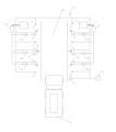
図3は、図中下側を車両の進入口、上側を車両の退出口とした洗浄システムの平面図である。図3によって、機器の配置を説明する。まず、車両進入口より順に、洗浄システム全体のON/OFFを行うキースイッチと洗浄コース選択を行うための受付装置を格納した受付ユニット11が設けられており、受付ユニット11より退出側に、車両前面洗浄開始位置を決定するための前面ビームセンサ6を配置している。また、車両前面を洗浄するために、前面ビームセンサ6より退出側に、斜め方向にノズル9が設けられた前面洗浄機1を設けた。前面洗浄機1より退出側には、車両Aに切れ目なく洗浄水を噴射するために、車両側面を洗浄するための側面洗浄機2を配置した。また、車両Aの後部を洗い残さないために、側面洗浄機2の次に側面ビームセンサ7を配置し、車両Aの側面後方部まで洗浄が出来るようになっている。加えて、側面洗浄機2より退出側に車両後部を洗浄するために、斜め方向に設けられた後面洗浄機3、更に退出側に後面ビームセンサ8といった配置としたことにより、車両側面後方部から車両後面に満遍なく洗浄水を噴射できる配置となっている。
FIG. 3 is a plan view of a cleaning system in which a vehicle entrance is shown on the lower side and a vehicle exit is shown on the upper side. The arrangement of equipment will be explained with reference to FIG. First, from the vehicle entrance, there is a
各洗浄機には、洗浄水の供給量の調整のための弁13が設けられている。弁13は各洗浄機の流量調整を個別に行うために、前面洗浄機1のための弁13a、側面洗浄機2のための弁13b、後面洗浄機3のための弁13cとする。車両Aの走行及び停止のタイミングを指示するための回転灯12(指示器)が取り付けられ、洗浄機2には図示しない非常停止スイッチが具備されている。該回転灯12は本実施形態においては、洗浄システム最後部に設置されているが、洗浄機の上部など、車両Aから視認できる位置に設置するならば、何処に置いてもよい。該ビームセンサ6、7、8は、洗浄機に組み込んだ場合に、洗浄機に設けられたノズルからの洗浄水の噴射による霧状の液滴によって、より誤検知が発生しやすくなるため、本実施形態では、ビームセンサ6、7、8を洗浄機本体とは別に設置することを想定しているが、洗浄機に組み込まれて使用されても問題ない。また、ビームセンサ6、7、8は投光部と受光部に分かれて構成されている。
Each washing machine is provided with a
以下により、図3から図9を用いて、洗車動作の流れを説明する。なお、以下の図では、検知中(遮光状態)のビームセンサの色を黒塗、未検知(通光状態)のビームセンサの色を白塗で表現している。 The flow of the car washing operation will be explained below using FIGS. 3 to 9. In the diagrams below, the beam sensor that is detecting (light blocking state) is shown in black, and the beam sensor that is not detecting (light passing state) is shown in white.
(通常洗浄)
図3において、受付ユニット11にてキースイッチを入れ、洗浄コースを選択し、ポンプ5が作動後、洗車をスタートする。洗車をスタート後、図4のように作業者が車両Aを走行路面Bの前面ビームセンサ6の検知位置まで走行する。作業者が車両Aを検知位置まで到達させると、前面ビームセンサ6が遮光され、車両Aを検知したと判断し、回転灯12が点灯する。作業者は、回転灯12が点灯したことを確認し、車両Aの走行を停止する。回転灯12点灯の所定時間後に制御ユニット10からの指示で、弁13aを開き、前面洗浄機1に設けられたノズル9が首振動作を開始するとともに、ノズル9から洗浄水を車両A前面に噴射させ、所定時間後に弁13aを閉じ、ノズル9の首振動作を停止させる。これにより、前面洗浄機1の車両前面への洗車動作を完了し、回転灯12を消灯させる。
(Normal cleaning)
In FIG. 3, the key switch is turned on at the
続いて、図5において、作業者が車両Aを走行路面Bの側面ビームセンサ7の検知位置まで走行する。車両Aが検知位置まで到達すると、車両Aによって側面ビームセンサ7が遮光され、車両Aを検知したと判断し、回転灯12が点灯する。作業者は、回転灯12が点灯したことを確認し、車両Aを停車する。回転灯12が点灯後、制御ユニット10からの指示で、弁13bを開き、側面洗浄機2に設けられたノズル9が首振動作を開始するとともに、ノズル9から洗浄水を車両A側面に噴射させる。作業者は、車両A側面を満遍なく洗浄するため、ノズル9から洗浄水を噴射中に、車両Aをゆっくりと走行させる。
Subsequently, in FIG. 5, the worker drives the vehicle A to the detection position of the
作業者が車両Aをゆっくりと走行させ、車両側面を満遍なく洗浄する。洗浄途中で、車両側面を遮光中であった前面ビームセンサ6が通光される。前面ビームセンサ6が通光してから更に車両Aを走行させると、後面ビームセンサ8が車両Aに遮られ、遮光状態となる。
A worker drives vehicle A slowly and thoroughly washes the side of the vehicle. During the cleaning, the
車両Aが図6の位置まで来ると、走行中の車両Aによって遮光中であったビームセンサ7が通光され、制御ユニット10にて、検知中の車両Aが側面洗浄機2の洗浄範囲から外れたことを判断し、車両Aの後部空間による誤検知防止のために側面ビームセンサ7が所定時間、通光であることを確認した後に、弁13bを閉じ、ノズル9の首振動作を停止させる。これにより、側面洗浄機2の車両側面への洗車動作を完了し、回転灯12を消灯させる。
When vehicle A reaches the position shown in FIG. After determining that it has come off and confirming that the
側面洗浄機2の車両側面への洗車動作を完了後、車両Aが図7の位置まで来ると、前面洗浄機1、側面洗浄機2が動作完了後、ビームセンサ8が遮光中である場合、車両Aが車両後面洗浄位置に進入したと判断し、制御ユニット10からの指示で、回転灯12を点灯させる。作業者は回転灯12の点灯を確認した後に、車両Aを停車する。回転灯12を点灯させてから、所定時間経過後に、制御ユニット10からの指示で、弁13cを開き、後面洗浄機3に設けられたノズル9が首振動作を開始する。ノズル9が首振動作を開始してから所定時間後に弁13cを閉じ、ノズル9の首振動作を停止させる。これにより、後面洗浄機3の車両後面への洗車動作を完了し、回転灯12を消灯させる。
When the vehicle A reaches the position shown in FIG. 7 after the
回転灯消灯後、車両Aを走行路面Bの外へ走行させると、遮光中であった後面ビームセンサ8が通光され、後面洗浄機3の洗車動作を完了する。これで通常の洗車工程は終了となる。
After the rotating light is turned off, when the vehicle A is driven out of the running road surface B, the
(追加洗浄)
その後、後面洗浄機3による後面再洗浄の待機状態に入る。待機状態に入って所定時間が経過しても、作業者が車両Aを後退させずに、後面ビームセンサ8が遮光状態にならない場合、洗車終了とする。また、待機状態に入ってから、図8のように、作業者が車両Aを後退させ、再度後面ビームセンサ8が遮光状態になった場合には、回転灯12が点灯する。回転灯12の点灯を作業者が確認し、車両Aを停止させる。所定時間経過後に後面洗浄機3の洗浄動作を開始し、車両後面を再洗浄する。最後に所定時間が経過するか、後面ビームセンサ8が通光状態になった場合、後面洗浄機3の弁13cを閉じ、ノズル9の首振動作を停止させることにより、回転灯が消灯し、図9のように車両Aを退出させて、洗車終了となる。
(Additional cleaning)
Thereafter, a standby state is entered for the rear
(異常発生)
さて、図10のように、側面ビームセンサ7(第2センサ)が洗浄水の噴射による誤検知を引き起こした場合については、前面洗浄機1の停止後に、遮光中の側面ビームセンサ7(第2センサ)が噴射した洗浄水の霧状の液滴によって遮光状態(OFF状態)を維持したまま、作業者によって走行中の車両Aが側面洗浄機2(洗浄ユニット)の洗浄範囲から外れ、制御ユニット10の指示で、弁13bを開いたまま、側面洗浄機2(洗浄ユニット)の洗車動作を継続してしまう。また、側面洗浄機2(洗浄ユニット)の洗車動作を完了出来ないため、前面洗浄機1及び側面洗浄機2が動作完了後、動作を開始するはずの後面洗浄機3での後面洗浄が不可能となる。
(Abnormal occurrence)
Now, as shown in FIG. 10, in the case where the side beam sensor 7 (second sensor) causes false detection due to the jet of cleaning water, after the
そこで側面洗浄機2(洗浄ユニット)を停止させ、後面洗浄機3の洗車動作を実施させるため、図10において、走行中の車両Aによって遮光(OFF状態)中であった後面ビームセンサ8(第2センサ)が通光(ON状態)された後、所定時間後に、後面ビームセンサ8(第2センサ)にて検知中の車両Aが後面洗浄機3の範囲から外れたことを確認する。そして、制御ユニット10の指示で、後面ビームセンサ8(第2センサ)の通光状態(ON状態)が所定時間継続した場合、側面ビームセンサ7(第1センサ)に対応した側面洗浄機2の弁13bを閉じ、ノズル9の首振動作を停止させ、側面洗浄機2(洗浄ユニット)のノズル9より噴射した洗浄水の霧状の液滴による遮光状態を解消する。
Therefore, in order to stop the side washer 2 (washing unit) and perform the car washing operation of the
すなわち、車両洗浄システムは、側面洗浄機2(洗浄ユニット)からの洗浄水の噴射を実行している最中に、後面ビームセンサ8(第2センサ)が遮光状態(OFF状態)から通光状態(ON状態)となって継続した場合に、側面洗浄機2(洗浄ユニット)からの洗浄水の噴射を停止させる機能を有している。これにより、誤検知による洗浄水が無駄に噴射されることを防止し、洗浄水を節約することができる。また、後面ビームセンサ8(第2センサ)の他に前面ビームセンサ6(第3センサ)が通光状態(ON状態)であることも確認することで、より誤検知を防止することができ、洗浄水を節約することができる。 That is, in the vehicle washing system, while the side washing machine 2 (washing unit) is spraying washing water, the rear beam sensor 8 (second sensor) changes from the light blocking state (OFF state) to the light passing state. It has a function of stopping the injection of washing water from the side washing machine 2 (washing unit) when it continues to be in the ON state. This prevents wasted cleaning water from being sprayed due to erroneous detection and saves cleaning water. In addition, by checking that the front beam sensor 6 (third sensor) in addition to the rear beam sensor 8 (second sensor) is in a light passing state (ON state), false detection can be further prevented. Washing water can be saved.
そして、車両Aは走行路面Bの外にいるため、後面ビームセンサ8では検知できず、後面洗浄機3による後面洗浄をスキップしたこととなる。そのため、後面洗浄機3による後面再洗浄の待機状態に入る。図9のように、待機状態に入って所定時間が経過してもビームセンサ7が遮光状態にならない場合、洗車終了とする。
Since the vehicle A is outside the traveling road surface B, the
また、図8のように、待機状態に入ってから、作業者が車両Aを走行させて、再度後面ビームセンサ8が遮光状態になった場合には、回転灯12が点灯する。作業者は、回転灯12の点灯を確認後、車両Aを停止させる。回転灯12の点灯後、所定時間が経過すると、後面洗浄機3の洗浄動作を開始し、車両後面を洗浄する。最後に所定時間が経過するか、後面ビームセンサ8が通光状態になった場合、後面洗浄機3の弁13cを閉じ、ノズル9の首振動作を停止させ、洗車終了とする。
Further, as shown in FIG. 8, when the worker drives the vehicle A after entering the standby state and the
図11は洗浄システムの洗浄機のノズルからの洗浄水噴射停止制御に関するパターン表であり、パターン1は3つの洗浄機のそれぞれに対応する3つのセンサを車両走行方向に沿って並べた場合である。センサが車両を検知していないことを表す通光状態とセンサが車両を検知している遮光状態でセンサの検知状態を表しており、通光状態のセンサに挟まれた遮光状態のセンサに対応した洗浄機が所定時間後に停止するように制御される。なお、パターン1は、3つの洗浄機のそれぞれに対応する3つのセンサを車両走行方向に沿って並べた場合だけでなく、通光状態の2台のセンサの間に挟まれたセンサに対応した洗浄機1台の停止制御を行う場合にも適用出来る。更に、パターン1のような両端の通光状態のセンサに挟まれた遮光状態のセンサが1つの場合だけでなく、パターン2のように通光状態のセンサに挟まれたセンサが複数であっても、停止制御を行う。また、2つの遮蔽状態のセンサが洗浄システムの両端にある必要はなく、パターン3のように遮光状態のセンサが通光状態のセンサに挟まれていれば、停止制御を行う。
FIG. 11 is a pattern table regarding the control to stop the injection of cleaning water from the nozzle of the cleaning machine in the cleaning system.
加えて、洗浄動作中に、前面ビームセンサ6、側面ビームセンサ7、後面ビームセンサ8の各ビームセンサのうち、少なくとも1つのセンサが車両Aを検知した状態から検知していない状態に移行後、所定時間経過すると、各洗浄機からの洗浄水の噴射を停止させるよう設定されていることも想定できる。この制御により、強風によるビームセンサの誤検知による洗浄機の誤動作を防止することができる。
In addition, during the cleaning operation, after at least one of the
以上、本実施形態における一車両洗浄システムは、車両に洗浄水を噴射する洗浄機と、前記洗浄機に対応した少なくとも2台の車両検知のためのセンサを備えている。第1のセンサが車両を検知すると洗浄水の噴射を開始し、第2のセンサが車両を検知しなくなってから、所定時間経過しても第1センサが車両を検知したままの場合に、前記洗浄機からの洗浄水の噴射を停止させるよう設定されている。 As described above, the vehicle cleaning system in this embodiment includes a cleaning machine that injects cleaning water onto a vehicle, and at least two sensors for detecting vehicles corresponding to the cleaning machine. When the first sensor detects a vehicle, it starts spraying cleaning water, and if the first sensor continues to detect the vehicle even after a predetermined period of time has passed after the second sensor no longer detects the vehicle, the first sensor starts spraying the cleaning water. It is set to stop spraying washing water from the washing machine.
また、本実施形態における車両洗浄システムは、車両に洗浄水を噴射する少なくとも3台の洗浄機と、各洗浄機に対応した3台のセンサを備えている。第2のセンサのみが車両を検知したままの場合に、検知状態のセンサに対応した洗浄機からの洗浄水の噴射を停止させるよう設定されている。 Further, the vehicle washing system in this embodiment includes at least three washing machines that spray washing water onto the vehicle, and three sensors corresponding to each washing machine. If only the second sensor continues to detect the vehicle, it is set to stop spraying washing water from the washing machine corresponding to the sensor in the detection state.
また、本発明の実施形態における他の車両洗浄システムは、車両に洗浄水を噴射する車両走行方向に並んだ、少なくとも1台の洗浄機と、少なくとも3台のセンサを備えている。第2のセンサのみが車両を検知したままの場合に、検知状態のセンサに対応した洗浄機からの洗浄水の噴射を停止させるよう設定されている。 Another vehicle washing system according to an embodiment of the present invention includes at least one washer arranged in the vehicle travel direction to spray washing water onto the vehicle, and at least three sensors. When only the second sensor continues to detect the vehicle, the system is configured to stop spraying washing water from the washer corresponding to the sensor that is in the detecting state.
また、本発明の実施形態における他の車両処理システムは、車両に洗浄水を噴射する洗浄機と、前記洗浄機に対応した少なくとも2台の車両検知のためのセンサを備えている。少なくともどちらか一方のセンサが車両を検知した状態から検知していない状態に移行してから所定時間経過後に、前記洗浄機からの洗浄水の噴射を停止させるよう設定されている。 Another vehicle processing system according to an embodiment of the present invention includes a washing machine that injects washing water onto a vehicle, and at least two sensors for detecting vehicles corresponding to the washing machine. The washing machine is set to stop spraying washing water after a predetermined period of time has elapsed since at least one of the sensors changed from a state in which it detected the vehicle to a state in which it did not detect the vehicle.
これら車両洗浄システムによれば、システムの最後部の後面センサの検知結果によって後面センサより前方に設けられた各センサに対応した洗浄機の洗浄水の噴射を停止することにより、洗浄機の誤動作による洗浄水の過剰噴射状態を解消することができる。 According to these vehicle washing systems, by stopping the injection of washing water from the washing machine corresponding to each sensor installed forward of the rear sensor based on the detection result of the rear sensor at the rear end of the system, It is possible to eliminate the excessive injection of cleaning water.
(第2実施形態)
前記第1実施形態では、洗浄ユニット(洗浄機)を3台、センサを3つ設けた場合について説明した。本発明に係る第2実施形態では、車両に対して洗浄液を噴射する処理機能を有する車両洗浄システム(単にシステムともいう。)として、洗浄ユニットを1台、センサを2つ設ける場合について、図面を参照して説明する。図12、図13および図14は、システム50の要部の模式的な正面図、平面図および側面図である。図15は、システム50に対する車両Cの位置状況をまとめた表である。図16は、システム50の処理機能の工程フロー図である。なお、システム50および車両CがXYZ座標空間に配置されたものとして、図中にX方向(車両方向に対応)、Y方向(車幅方向に対応)、Z方向(車高方向に対応)を付す場合ある。
(Second embodiment)
In the first embodiment, a case has been described in which three cleaning units (cleaning machines) and three sensors are provided. In the second embodiment of the present invention, a vehicle cleaning system (also simply referred to as a system) having a processing function of injecting cleaning liquid to a vehicle is provided with one cleaning unit and two sensors. Refer to and explain. 12, 13, and 14 are a schematic front view, plan view, and side view of the main parts of the
システム50は、車両Cの車長方向(X方向)に沿って設けられた洗浄ユニット51、第1センサ52、および第2センサ53を備えている。そして、システム50は、作業者によって車両Cが進入側(図13中、下側)から退出側(図13中、上側)へ走行路面を走行する際に、車両Cに対して種々の処理を施す機能を有している。システム50では、第1センサ52、洗浄ユニット51、および第2センサ53の順で車両Cが通過することとなる。なお、システム50では、洗浄ユニット51に第1センサ52および第2センサ53が取り付けられており、進入側に第1センサ52、退出側に第2センサ53が設けられている。
The
洗浄ユニット51は、車両Cに対して洗浄液を噴射する機能(例えば、ノズルを揺動させて高圧水を噴射する。)を有している。第1センサ52および第2センサ53は、車両Cを検知する機能を有している。システム50では、第1センサ52および第2センサ53がON状態のときを物体を検知していないもの(車両Cの非検知を意図する。)とし、OFF状態のときを物体を検知しているもの(車両Cの検知を意図する。)としている。
The
また、システム50は、受付ユニット60を備えている。受付ユニット60は、洗浄コースの設定や開始を受け付ける機能を有している。受付ユニット60は、第1センサ52よりも進入側に設けられている。また、システム50は、指示器61を備えている。指示器61は、車両Cの作業者に対して車両Cの移動や停止を指示する機能を有している。指示器61は、車両Cの進行方向に対して洗浄ユニット51の両側(進入側および退出側)に設けられている。
The
ここで、システム50に車両Cが進入してから退出するまでの状況について説明する。車両Cの進入に先立ち、作業者(あるいは補助者)によって受付ユニット60で洗浄コースの受付が行われる。受付ユニット60の開始ボタンが押されることで、指示器61から作業者に指示が出される。これにより、作業者は車両Cを進入(前進)させることができる。
Here, the situation from when the vehicle C enters the
時間t1(図15参照、以下同じ。)の状況では、車両Cが第1センサ52の検知位置、および第2センサ53の検知位置に到達していない。また、洗浄ユニット51の洗浄範囲外にある。洗浄範囲内に車両Cがなく、車両Cを洗浄する必要がないため、システム50の正常な状態(意図した状態)としては、洗浄ユニット51から洗浄液が噴射(噴出)されない。
In the situation at time t1 (see FIG. 15, the same applies hereinafter), the vehicle C has not reached the detection position of the
続いて、時間t2の状況では、車両Cが第2センサ53の検知位置に到達していないが、第1センサ52の検知位置に到達している(存在する)。また、洗浄ユニット51の洗浄範囲内にある。このため、車両Cを洗浄することができるよう、システム50の正常な状態としては、洗浄ユニット51から洗浄液が噴射される。
Subsequently, in the situation at time t2, the vehicle C has not reached the detection position of the
続いて、時間t3の状況(図13参照)では、車両Cが第1センサ52および第2センサ53の検知位置に到達している。また、洗浄ユニット51の洗浄範囲内にある。このため、車両Cを洗浄することができるよう、システム50の正常な状態としては、洗浄ユニット51から洗浄液が噴射される。
Subsequently, in the situation at time t3 (see FIG. 13), the vehicle C has reached the detection positions of the
続いて、時間t4の状況では、車両Cが第1センサ52の検知位置を通り抜ける(存在しない)ものの、第2センサ53の検知位置に到達している。また、洗浄ユニット51の洗浄範囲内にある。このため、車両Cを洗浄することができるよう、システム50の正常な状態としては、洗浄ユニット51から洗浄液が噴射される。
Subsequently, in the situation at time t4, although the vehicle C passes through (does not exist) the detection position of the
続いて、時間t5の状況では、車両Cが第1センサ52および第2センサの検知位置を通り抜けている。また、洗浄ユニット51の洗浄範囲外にある。洗浄範囲内に車両Cがなく、車両Cを洗浄する必要がないため、システム50の正常な状態(意図した状態)としては、洗浄ユニット51から洗浄液が噴射(噴出)されない。
Subsequently, at time t5, the vehicle C passes through the detection positions of the
ここで、本発明者らが検討したシステム50の動作の一例(以下、検討例という。)について説明する。前述した状況(時間t1~t5)を鑑みれば、第1センサ52がOFF状態になった(車両Cを検知)ときに洗浄ユニット51から洗浄液を噴射させ、第2センサ53がON状態になった(車両Cを非検知)ときに噴射を停止させるよう動作させることができる。このとき、第1センサ52がOFF状態であれば、車両Cがあるものとして洗浄ユニット51から洗浄液を噴出させている。なお、このようや状況は、車両Cが第2センサ53の検知位置まで到達した後に、後退する場合を考慮している。
Here, an example of the operation of the
しかしながら、例えば、気象条件が悪く、洗浄ユニット51から噴射された洗浄液(霧、液滴、飛沫の状態を含む。)が風向きによって第1センサ52側へ流され、第1センサ51の検知位置に車両Cがないにも関わらず、第1センサ52が洗浄液を検知してOFF状態であることもあり得る。また、風向きによって第2センサ53側へ流れ、第2センサ53の検知位置に車両Cがないにも関わらず、第2センサ53が洗浄液を検知してOFF状態であることもあり得る。そこで、システム50は、次に示す処理機能(図16参照)を有している。
However, for example, if the weather conditions are bad, the cleaning liquid (including mist, droplets, and splashes) sprayed from the
次に、システム50の処理機能(処理方法として捉えることもできる。)について説明する。まず、システム50が処理を開始すると、第1センサ52および第2センサ53がON状態となる(工程S10)。処理開始時点では、洗浄ユニット51からは洗浄液は噴射されていない。このとき、正常な状態では、車両Cが洗浄される前となる。
Next, the processing function (which can also be considered as a processing method) of the
次いで、システム50は、第1センサ52がOFF状態となるか否かを判断する(工程S20)。第1センサ52がOFF状態となったら洗浄ユニット51から洗浄液を噴射させる(工程S30)。このとき、正常な状態では、車両Cが洗浄される。
Next, the
次いで、システム50は、第2センサ53がOFF状態となるか否かを判断する(工程S40)。この判断がされているとき、正常状態では、車両Cが洗浄される。
Next, the
次いで、システム50は、第2センサ53がOFF状態となると(工程S40)、第1センサ52または第2センサ53の少なくともいずれか一方がON状態となるか否かを判断する(工程S50)。この判断がされているとき、正常状態では、車両Cが洗浄される。
Next, when the
そして、第1センサ52または第2センサ53の少なくともいずれか一方がON状態となった場合、その状態が所定時間継続するか否かを判断する(工程S60)。前述したように、第1センサ52、第2センサ53の検知位置に車両Cがないにも関わらず、風向きによって流れた洗浄液を検知してしまい、誤検知の状態となるおそれがある。
Then, when at least one of the
そこで、洗浄ユニット51からの洗浄液の噴出を実行している最中に、第1センサ52または第2センサ53の少なくともいずれか一方がON状態となって所定時間継続した場合に、洗浄ユニット51からの洗浄液の噴射を停止させる(工程S70)。すなわち、第1センサ52または第2センサ53の少なくともいずれか一方がON状態となったにも関わらず、他方が所定時間OFF状態のままであるのは、誤検知によるものと判断し、洗浄ユニット51からの洗浄液の噴射を停止させる。これにより、誤検知による洗浄液が無駄に噴射されることを防止し、洗浄液を節約することができる。
Therefore, if at least one of the
また、洗浄ユニット51からの洗浄液の噴射を停止させるタイミングを、例えば、受付ユニット60での選択により車両Cの種類によって設定しておく。このような設定機能によれば、予め車両Cの種類と継続させる所定時間とを対比させることで、洗浄液が無駄に噴射されることを防止し、洗浄液を節約することができる。なお、洗浄液の節約のため、第1センサ52がOFF状態(工程S20)となってから時間を計り始め、所定時間(工程S60での継続時間よりも長い。)を経過したら、最終的なタイムアップとして洗浄液の噴射を停止させることもできる。
Further, the timing for stopping the injection of the cleaning liquid from the
次に、このような処理機能を有するシステム50の具体的構成について説明する。洗浄ユニット51は、敷設面G(走行路面を含む。)に起立するよう固定して設けられている。システム50では、洗浄ユニット51は対をなし(このため、洗浄ユニット51A、51Bともいう。)、車両Cの走行路面を挟むように車幅方向(Y方向)に対向して、洗浄ユニット51A、51Bが設けられている。
Next, a specific configuration of the
第1センサ52は、洗浄ユニット51の進入側面に取り付けられている。第2センサ53は、洗浄ユニット51の退出側面に取り付けられている。システム50では、第1センサ52および第2センサ53として、ビームセンサ(光電センサ)を用いている。このため、第1センサ52の発光部52aが洗浄ユニット51Aの進入側面に取り付けられる一方、第1センサ52の受光部52bが洗浄ユニット51Bの進入側面に取り付けられる。また、第2センサ53の発光部53aが洗浄ユニット51Aの退出側面に取り付けられる一方、第2センサ53の受光部53bが洗浄ユニット51Bの退出側面に取り付けられる。
The
洗浄ユニット51は、第1噴射口54と、第2噴射口55とを備えている。第1噴射口54および第2噴射口55は、この順に敷設面Gからの高さ、すなわち車高方向(Z方向)の高さが高くなるように設けられている。噴射口54、55は、例えば、洗浄液を噴射する機能を有するノズルの先端に設けられている。例えば、ポンプを駆動してタンク内の洗浄液がノズルに供給される。ノズルが首振り機構を備えている場合には、噴出口54、55が上下方向(または、左右方向、回転方向でもよい。)に可動するのに伴って、洗浄液が広範囲に噴射される。
The
また、洗浄ユニット51は、第1板56と、第2板57と、第3板58とを備えている。第1板56は、第1噴出口54(およびその可動範囲)を露出する開口を有し、鉛直に立てて設けられている。また、第2板57は、第2噴出口55(およびその可動範囲)を露出する開口を有し、鉛直に立てて設けられている。そして、第2板57は、車両Cの車高方向(Z方向)において第1板56より高く、車幅方向(Y方向)において車両C(走行路面)に対して第1板56よりも奥に設けられている。また、第3板58は、第1板56より高く、第2板57よりも低い位置にあり、第1板56から第2板57にかけて連続面を形成するように、傾斜して設けられている。
Further, the
このように連続面を設けることで、周囲(特に、走行路面外側)へ洗浄液が飛び散らないようにすることができる。また、奥まった位置で第2噴出口55が上下にも揺動するので、第3板58を傾斜させることで、第2噴出口55から噴出される洗浄液を第3板58に当たらずに車両Cまで到達させることができる。また、第2板57を車両C(走行路面)に対して奥に設けることで、車両Cのサイドミラーなどの装備品との接触を回避させることができる。また、洗浄ユニット51の上部に付着した液体が自重によってスムーズに流れ落ちるようにすることができる。このため、システム50が回収装置を備える場合は、敷設面Gで回収し易くなる。
By providing such a continuous surface, it is possible to prevent the cleaning liquid from scattering to the surroundings (particularly to the outside of the road surface). In addition, since the
また、図13に示すように、洗浄ユニット51Aに設けられる第1噴出口54、第2噴出口55と、洗浄ユニット51Bに設けられる第1噴出口54、第2噴出口55とは、車長方向(X方向)にずらして設けられている。仮にずらして設けられていないと、車両Cが退出する際に、洗浄ユニット51Aからの洗浄液と洗浄ユニット51Bからの洗浄液が衝突して、飛沫となって風(気象条件)の影響を受けやすくなってしまう。そして、場合によっては、第1センサ52や第2センサ53での誤検知につながってしまう。そこで、洗浄ユニット51Aと洗浄ユニット51Aの噴出口をずらすことで、第1センサ52や第2センサ53の誤検知による洗浄液が無駄に噴射されることを防止し、洗浄液を節約することができる。
Further, as shown in FIG. 13, the
そして、センサ52、53は、車両Cの車幅方向(Y方向)において、板56、57、58より車両C(走行路面)に対して奥に設けられている。このため、センサ52、53を洗浄ユニット51に取り付ける構成としても、センサ52、53の動作に影響を及ぶすことを防止することができる。
The
例えば、噴出口54から噴射された洗浄液は車両Cにあたり、走行路面外側へ跳ね返ってしまう。そこで、センサ52、53から車幅方向に離れた位置に噴出口54を設け、更にこの噴出口54が開口される第1板56によって洗浄液を受け止めることで、センサ52、53の動作に影響を及ぼすことを防止することができる。なお、センサ52、53は、車両Cの車高方向(Z方向)において第1板56の寸法内の高さに設けられている。
For example, the cleaning liquid injected from the
また、システム50は、下部洗浄ユニット62を備えている。下部洗浄ユニット62は、車両Cの下部(下面)に対して洗浄液を噴射する処理機能を有している。また、下部洗浄ユニット62は、一対の洗浄ユニット51A、51Bの間で敷設面Gに設けられている。下部洗浄ユニット62は、例えば、車幅方向(Y方向)に延在するパイプ(不図示)が敷設面Gに埋め込まれるよう設けられ、パイプを介して複数のノズル64から洗浄液を噴射する機能を有している。なお、ノズル64は、パイプに固定でも揺動可能であってもよい。
The
この下部洗浄ユニット62は、退出側の第2センサ53より進入側の第1センサ52の近くに設けられている。これにより、車両Cが進入したら直ぐにでも車両Cの下部が洗浄されるが、仮に車両Cの側面へ弾き飛ばされた泥などの汚れがあったとしても、後で洗浄ユニット51で車両Cの側面が洗浄されるため、泥などが付着することを防止することができる。
This
また、システム50は、アーム65、66を備えている。第1センサ52および第2センサ53は、洗浄ユニット51に取り付けられるが、それぞれ車長方向(X方向)に延在するアーム65、66を介している。ここで、進入側の第1センサ52に用いられるアーム65は、退出側の第2センサ53に用いられるアーム66よりも長くなっている。下部洗浄ユニット62が進入側に設けられると、進入側の第1センサ52は、下部洗浄ユニット62から噴射される洗浄液の影響を受けやすくなってしまう。すなわち、第1センサ52は、誤検知しやすくなってしまう。そこで、アーム65を長くすることで、第1センサ52の誤検知による洗浄液が無駄に噴射されることを防止し、洗浄液を節約することができる。
The
また、システム50は、カバー70を備えている。カバー70は、例えば、フード状であり、第1センサ52の発光部52a、受光部52bや第2センサ53の発光部53a、受光部53bに被せ、これらに洗浄液が付着しないように保護するものである。これにより、第1センサ52や第2センサ53の誤検知による洗浄液が無駄に噴射されることを防止し、洗浄液を節約することができる。
The
以上、本発明を実施形態に基づき具体的に説明したが、本発明は前記実施形態に限定されるものではなく、その要旨を逸脱しない範囲で種々変更可能であることはいうまでもない。 Although the present invention has been specifically described above based on the embodiments, it goes without saying that the present invention is not limited to the embodiments described above, and can be modified in various ways without departing from the gist thereof.
例えば、前記実施形態では、受付ユニットで車種を選択させる場合について説明した。これに限らず、車両に対して相対的に車長方向に移動可能なフレームに設けられた車形センサによって車種を判断させることもできる。 For example, in the embodiment described above, a case has been described in which the reception unit selects the vehicle type. The present invention is not limited to this, and the type of vehicle may be determined by a vehicle shape sensor provided on a frame that is movable in the longitudinal direction relative to the vehicle.
2 側面洗浄機、 7 側面ビームセンサ、 8 後面ビームセンサ。 2 side cleaning machine, 7 side beam sensor, 8 rear beam sensor.
Claims (5)
前記車両の車長方向に沿って設けられた洗浄ユニット、第1センサ、および第2センサを備え、
前記第1センサが前記車長方向の一方側に設けられ、
前記第2センサが前記車長方向の他方側に設けられ、
前記洗浄ユニットが前記第2センサよりも前記一方側に設けられ、
前記処理機能は、前記第1センサがON状態からOFF状態となって前記洗浄ユニットからの洗浄液の噴射を開始し、前記第2センサもON状態からOFF状態となった後、前記洗浄ユニットからの洗浄液の噴射を実行している最中に、前記第1センサまたは前記第2センサがOFF状態からON状態となって所定時間経過した場合に、前記洗浄ユニットからの洗浄液の噴射を停止させる機能を有する、
ことを特徴とする車両洗浄システム。 A vehicle cleaning system having a processing function of injecting a cleaning liquid to a vehicle,
comprising a cleaning unit, a first sensor, and a second sensor provided along the vehicle length direction of the vehicle,
the first sensor is provided on one side in the vehicle length direction,
the second sensor is provided on the other side in the vehicle length direction,
The cleaning unit is provided on the one side of the second sensor,
The processing function starts spraying the cleaning liquid from the cleaning unit when the first sensor changes from the ON state to the OFF state, and after the second sensor also changes from the ON state to the OFF state, the processing function starts spraying the cleaning liquid from the cleaning unit. A function for stopping the injection of the cleaning liquid from the cleaning unit when a predetermined time elapses after the first sensor or the second sensor changes from an OFF state to an ON state while the cleaning liquid is being sprayed. have,
A vehicle washing system characterized by:
前記車両の車長方向に沿って設けられた洗浄ユニット、第1センサ、および第2センサを備え、
前記処理機能は、前記洗浄ユニットからの洗浄液の噴射を実行している最中に、前記第1センサまたは前記第2センサの少なくともいずれか一方がOFF状態からON状態となって継続した場合に、前記洗浄ユニットからの洗浄液の噴射を停止させる機能を有し、
前記洗浄ユニットは、第1および第2噴射口と、前記第1噴射口を露出する開口を有する第1板と、前記第2噴射口を露出する開口を有する第2板と、を備え、
前記車両の車高方向において前記第1板より前記第2板が高く設けられ、
前記車両の車幅方向において前記第1板より前記第2板が奥に設けられ、
前記第1および第2センサが、前記車両の車高方向において前記第1板の寸法内の高さに設けられ、かつ前記車両の車幅方向において前記第2板より奥に設けられている、
車両洗浄システム。 A vehicle cleaning system having a processing function of injecting a cleaning liquid to a vehicle,
comprising a cleaning unit, a first sensor, and a second sensor provided along the vehicle length direction of the vehicle,
The processing function is performed when at least one of the first sensor and the second sensor changes from an OFF state to an ON state and continues while spraying the cleaning liquid from the cleaning unit. It has a function of stopping the injection of cleaning liquid from the cleaning unit,
The cleaning unit includes first and second injection ports, a first plate having an opening exposing the first injection port, and a second plate having an opening exposing the second injection port. ,
The second plate is provided higher than the first plate in the vehicle height direction of the vehicle,
The second plate is provided further back than the first plate in the vehicle width direction of the vehicle,
The first and second sensors are provided at a height within the dimensions of the first plate in the vehicle height direction of the vehicle, and are provided deeper than the second plate in the vehicle width direction of the vehicle,
Vehicle cleaning system.
前記下部洗浄ユニットは、前記第2センサより前記第1センサの近くに設けられており、
前記第1センサおよび前記第2センサがそれぞれ第1アームおよび第2アームを介して前記洗浄ユニットに取り付けられ、
前記第1アームが前記第2アームよりも長い、
請求項1または2記載の車両洗浄システム。 comprising a lower part cleaning unit having a processing function of injecting a cleaning liquid to the lower part of the vehicle,
The lower cleaning unit is provided closer to the first sensor than the second sensor,
the first sensor and the second sensor are attached to the cleaning unit via a first arm and a second arm, respectively;
the first arm is longer than the second arm;
The vehicle cleaning system according to claim 1 or 2.
前記第3センサ、前記洗浄ユニット、前記第1センサ、および前記第2センサは、この順に前記車両が通過するよう配置され、
前記処理機能は、前記洗浄ユニットからの洗浄液の噴射を実行している最中に、前記第3センサがON状態で、かつ前記第2センサがOFF状態からON状態となって継続した場合に、前記洗浄ユニットからの洗浄液の噴射を停止させる機能を有する、
請求項1~3のいずれか一項に記載の車両洗浄システム。 comprising a third sensor provided along the vehicle length direction of the vehicle,
The third sensor, the cleaning unit, the first sensor, and the second sensor are arranged so that the vehicle passes in this order,
The processing function is performed when the third sensor is in the ON state and the second sensor continues from the OFF state to the ON state while the cleaning liquid is being sprayed from the cleaning unit. having a function of stopping the injection of cleaning liquid from the cleaning unit;
The vehicle cleaning system according to any one of claims 1 to 3.
請求項1~4のいずれか一項に記載の車両洗浄システム。 The processing function has a function of setting a timing for stopping the injection of cleaning liquid from the cleaning unit depending on the type of the vehicle.
The vehicle cleaning system according to any one of claims 1 to 4.
Applications Claiming Priority (2)
| Application Number | Priority Date | Filing Date | Title |
|---|---|---|---|
| JP2019187945 | 2019-10-11 | ||
| JP2019187945 | 2019-10-11 |
Publications (3)
| Publication Number | Publication Date |
|---|---|
| JP2021062862A JP2021062862A (en) | 2021-04-22 |
| JP2021062862A5 JP2021062862A5 (en) | 2022-07-15 |
| JP7454482B2 true JP7454482B2 (en) | 2024-03-22 |
Family
ID=75487377
Family Applications (1)
| Application Number | Title | Priority Date | Filing Date |
|---|---|---|---|
| JP2020172132A Active JP7454482B2 (en) | 2019-10-11 | 2020-10-12 | vehicle cleaning system |
Country Status (1)
| Country | Link |
|---|---|
| JP (1) | JP7454482B2 (en) |
Citations (2)
| Publication number | Priority date | Publication date | Assignee | Title |
|---|---|---|---|---|
| JP2003160033A (en) | 2001-11-28 | 2003-06-03 | Daifuku Co Ltd | Car washing device |
| JP2016078514A (en) | 2014-10-10 | 2016-05-16 | エムケー精工株式会社 | Car washing machine |
Family Cites Families (3)
| Publication number | Priority date | Publication date | Assignee | Title |
|---|---|---|---|---|
| JPS59216753A (en) * | 1983-05-21 | 1984-12-06 | Hino Motors Ltd | Carwash |
| JPH07246917A (en) * | 1994-03-08 | 1995-09-26 | Komatsu Ltd | Cleaning deice for wheel surroundings of dump truck |
| JP3718982B2 (en) * | 1998-01-12 | 2005-11-24 | 株式会社タツノ・メカトロニクス | Gate-type car wash machine |
-
2020
- 2020-10-12 JP JP2020172132A patent/JP7454482B2/en active Active
Patent Citations (2)
| Publication number | Priority date | Publication date | Assignee | Title |
|---|---|---|---|---|
| JP2003160033A (en) | 2001-11-28 | 2003-06-03 | Daifuku Co Ltd | Car washing device |
| JP2016078514A (en) | 2014-10-10 | 2016-05-16 | エムケー精工株式会社 | Car washing machine |
Also Published As
| Publication number | Publication date |
|---|---|
| JP2021062862A (en) | 2021-04-22 |
Similar Documents
| Publication | Publication Date | Title |
|---|---|---|
| JP5747829B2 (en) | Car wash machine | |
| KR101386802B1 (en) | Jetting Apparatus for car washing device | |
| JP7454482B2 (en) | vehicle cleaning system | |
| US7562413B2 (en) | Compact vehicle wash system | |
| JP6455919B2 (en) | Car wash machine | |
| JP4922789B2 (en) | Car wash machine | |
| JP4400476B2 (en) | Car wash machine | |
| JP4739135B2 (en) | Car wash method in car wash machine | |
| JP2010018216A (en) | Car washer | |
| JP2009214772A (en) | Car wash facility | |
| JP4597684B2 (en) | Car lower cleaning apparatus and car wash machine equipped with the apparatus | |
| JP6308174B2 (en) | Car wash machine and control method of car wash machine | |
| JP6684080B2 (en) | Car wash equipment | |
| JP6264263B2 (en) | Car wash machine and car wash method | |
| JP2020142801A (en) | Vehicle washer | |
| JP6710520B2 (en) | Car wash equipment | |
| JP6821427B2 (en) | Car wash device | |
| JP3954926B2 (en) | Car wash equipment | |
| JP2597904B2 (en) | Car wash machine | |
| JP2019156074A (en) | Vehicle washing device | |
| JP6853641B2 (en) | Body lower part cleaning device | |
| JP2925828B2 (en) | Tire cleaning equipment in car washer | |
| JP4380474B2 (en) | How to wash a car wash | |
| JP2991022B2 (en) | Car wash machine | |
| JP3815672B2 (en) | Gate-type car wash equipment |
Legal Events
| Date | Code | Title | Description |
|---|---|---|---|
| A521 | Request for written amendment filed |
Free format text: JAPANESE INTERMEDIATE CODE: A523 Effective date: 20220705 |
|
| A621 | Written request for application examination |
Free format text: JAPANESE INTERMEDIATE CODE: A621 Effective date: 20220705 |
|
| A977 | Report on retrieval |
Free format text: JAPANESE INTERMEDIATE CODE: A971007 Effective date: 20230314 |
|
| A131 | Notification of reasons for refusal |
Free format text: JAPANESE INTERMEDIATE CODE: A131 Effective date: 20230404 |
|
| A521 | Request for written amendment filed |
Free format text: JAPANESE INTERMEDIATE CODE: A523 Effective date: 20230601 |
|
| A131 | Notification of reasons for refusal |
Free format text: JAPANESE INTERMEDIATE CODE: A131 Effective date: 20230704 |
|
| A521 | Request for written amendment filed |
Free format text: JAPANESE INTERMEDIATE CODE: A523 Effective date: 20230904 |
|
| A131 | Notification of reasons for refusal |
Free format text: JAPANESE INTERMEDIATE CODE: A131 Effective date: 20231129 |
|
| A521 | Request for written amendment filed |
Free format text: JAPANESE INTERMEDIATE CODE: A523 Effective date: 20231212 |
|
| TRDD | Decision of grant or rejection written | ||
| A01 | Written decision to grant a patent or to grant a registration (utility model) |
Free format text: JAPANESE INTERMEDIATE CODE: A01 Effective date: 20240305 |
|
| A61 | First payment of annual fees (during grant procedure) |
Free format text: JAPANESE INTERMEDIATE CODE: A61 Effective date: 20240311 |
|
| R150 | Certificate of patent or registration of utility model |
Ref document number: 7454482 Country of ref document: JP Free format text: JAPANESE INTERMEDIATE CODE: R150 |