JP7453152B2 - Automatic positioning of antenna connectors for magnetic resonance imaging - Google Patents
Automatic positioning of antenna connectors for magnetic resonance imaging Download PDFInfo
- Publication number
- JP7453152B2 JP7453152B2 JP2020555125A JP2020555125A JP7453152B2 JP 7453152 B2 JP7453152 B2 JP 7453152B2 JP 2020555125 A JP2020555125 A JP 2020555125A JP 2020555125 A JP2020555125 A JP 2020555125A JP 7453152 B2 JP7453152 B2 JP 7453152B2
- Authority
- JP
- Japan
- Prior art keywords
- antenna
- magnetic resonance
- resonance imaging
- connector
- medical device
- Prior art date
- Legal status (The legal status is an assumption and is not a legal conclusion. Google has not performed a legal analysis and makes no representation as to the accuracy of the status listed.)
- Active
Links
- 238000002595 magnetic resonance imaging Methods 0.000 title claims description 186
- 230000005855 radiation Effects 0.000 claims description 32
- 238000003384 imaging method Methods 0.000 claims description 30
- 230000015654 memory Effects 0.000 claims description 30
- 238000001959 radiotherapy Methods 0.000 claims description 26
- 238000000034 method Methods 0.000 claims description 17
- 238000004590 computer program Methods 0.000 claims description 12
- 230000001678 irradiating effect Effects 0.000 claims 1
- 238000003860 storage Methods 0.000 description 21
- 238000002059 diagnostic imaging Methods 0.000 description 16
- 230000003287 optical effect Effects 0.000 description 11
- 238000010586 diagram Methods 0.000 description 10
- 230000006870 function Effects 0.000 description 8
- 230000009286 beneficial effect Effects 0.000 description 7
- 238000001208 nuclear magnetic resonance pulse sequence Methods 0.000 description 7
- 238000004891 communication Methods 0.000 description 6
- 238000012545 processing Methods 0.000 description 5
- 230000005540 biological transmission Effects 0.000 description 4
- 238000007726 management method Methods 0.000 description 4
- 230000001419 dependent effect Effects 0.000 description 3
- 230000001902 propagating effect Effects 0.000 description 3
- 238000007792 addition Methods 0.000 description 2
- 210000003484 anatomy Anatomy 0.000 description 2
- 238000009826 distribution Methods 0.000 description 2
- 230000033001 locomotion Effects 0.000 description 2
- 238000009206 nuclear medicine Methods 0.000 description 2
- 239000000700 radioactive tracer Substances 0.000 description 2
- 239000007787 solid Substances 0.000 description 2
- 230000003068 static effect Effects 0.000 description 2
- 238000003325 tomography Methods 0.000 description 2
- 238000012800 visualization Methods 0.000 description 2
- 241000699670 Mus sp. Species 0.000 description 1
- 238000007405 data analysis Methods 0.000 description 1
- 238000001514 detection method Methods 0.000 description 1
- 230000000694 effects Effects 0.000 description 1
- 239000000835 fiber Substances 0.000 description 1
- 230000005251 gamma ray Effects 0.000 description 1
- 239000004973 liquid crystal related substance Substances 0.000 description 1
- 238000004519 manufacturing process Methods 0.000 description 1
- 238000013507 mapping Methods 0.000 description 1
- 239000000463 material Substances 0.000 description 1
- 238000005259 measurement Methods 0.000 description 1
- 239000002245 particle Substances 0.000 description 1
- 230000037361 pathway Effects 0.000 description 1
- 238000002600 positron emission tomography Methods 0.000 description 1
- 238000003825 pressing Methods 0.000 description 1
- 230000000241 respiratory effect Effects 0.000 description 1
- 230000000284 resting effect Effects 0.000 description 1
- 238000002603 single-photon emission computed tomography Methods 0.000 description 1
- 238000002560 therapeutic procedure Methods 0.000 description 1
- 210000003813 thumb Anatomy 0.000 description 1
- 230000000007 visual effect Effects 0.000 description 1
Images


Classifications
-
- A—HUMAN NECESSITIES
- A61—MEDICAL OR VETERINARY SCIENCE; HYGIENE
- A61B—DIAGNOSIS; SURGERY; IDENTIFICATION
- A61B5/00—Measuring for diagnostic purposes; Identification of persons
- A61B5/05—Detecting, measuring or recording for diagnosis by means of electric currents or magnetic fields; Measuring using microwaves or radio waves
- A61B5/055—Detecting, measuring or recording for diagnosis by means of electric currents or magnetic fields; Measuring using microwaves or radio waves involving electronic [EMR] or nuclear [NMR] magnetic resonance, e.g. magnetic resonance imaging
-
- G—PHYSICS
- G01—MEASURING; TESTING
- G01R—MEASURING ELECTRIC VARIABLES; MEASURING MAGNETIC VARIABLES
- G01R33/00—Arrangements or instruments for measuring magnetic variables
- G01R33/20—Arrangements or instruments for measuring magnetic variables involving magnetic resonance
- G01R33/28—Details of apparatus provided for in groups G01R33/44 - G01R33/64
- G01R33/32—Excitation or detection systems, e.g. using radio frequency signals
- G01R33/34—Constructional details, e.g. resonators, specially adapted to MR
- G01R33/34007—Manufacture of RF coils, e.g. using printed circuit board technology; additional hardware for providing mechanical support to the RF coil assembly or to part thereof, e.g. a support for moving the coil assembly relative to the remainder of the MR system
-
- A—HUMAN NECESSITIES
- A61—MEDICAL OR VETERINARY SCIENCE; HYGIENE
- A61N—ELECTROTHERAPY; MAGNETOTHERAPY; RADIATION THERAPY; ULTRASOUND THERAPY
- A61N5/00—Radiation therapy
- A61N5/10—X-ray therapy; Gamma-ray therapy; Particle-irradiation therapy
- A61N5/1048—Monitoring, verifying, controlling systems and methods
- A61N5/1049—Monitoring, verifying, controlling systems and methods for verifying the position of the patient with respect to the radiation beam
-
- G—PHYSICS
- G01—MEASURING; TESTING
- G01R—MEASURING ELECTRIC VARIABLES; MEASURING MAGNETIC VARIABLES
- G01R33/00—Arrangements or instruments for measuring magnetic variables
- G01R33/20—Arrangements or instruments for measuring magnetic variables involving magnetic resonance
- G01R33/28—Details of apparatus provided for in groups G01R33/44 - G01R33/64
- G01R33/32—Excitation or detection systems, e.g. using radio frequency signals
- G01R33/36—Electrical details, e.g. matching or coupling of the coil to the receiver
-
- A—HUMAN NECESSITIES
- A61—MEDICAL OR VETERINARY SCIENCE; HYGIENE
- A61N—ELECTROTHERAPY; MAGNETOTHERAPY; RADIATION THERAPY; ULTRASOUND THERAPY
- A61N5/00—Radiation therapy
- A61N5/10—X-ray therapy; Gamma-ray therapy; Particle-irradiation therapy
- A61N5/1048—Monitoring, verifying, controlling systems and methods
- A61N5/1049—Monitoring, verifying, controlling systems and methods for verifying the position of the patient with respect to the radiation beam
- A61N2005/1055—Monitoring, verifying, controlling systems and methods for verifying the position of the patient with respect to the radiation beam using magnetic resonance imaging [MRI]
-
- G—PHYSICS
- G01—MEASURING; TESTING
- G01R—MEASURING ELECTRIC VARIABLES; MEASURING MAGNETIC VARIABLES
- G01R33/00—Arrangements or instruments for measuring magnetic variables
- G01R33/20—Arrangements or instruments for measuring magnetic variables involving magnetic resonance
- G01R33/28—Details of apparatus provided for in groups G01R33/44 - G01R33/64
- G01R33/283—Intercom or optical viewing arrangements, structurally associated with NMR apparatus
-
- G—PHYSICS
- G01—MEASURING; TESTING
- G01R—MEASURING ELECTRIC VARIABLES; MEASURING MAGNETIC VARIABLES
- G01R33/00—Arrangements or instruments for measuring magnetic variables
- G01R33/20—Arrangements or instruments for measuring magnetic variables involving magnetic resonance
- G01R33/28—Details of apparatus provided for in groups G01R33/44 - G01R33/64
- G01R33/32—Excitation or detection systems, e.g. using radio frequency signals
- G01R33/36—Electrical details, e.g. matching or coupling of the coil to the receiver
- G01R33/3692—Electrical details, e.g. matching or coupling of the coil to the receiver involving signal transmission without using electrically conductive connections, e.g. wireless communication or optical communication of the MR signal or an auxiliary signal other than the MR signal
-
- G—PHYSICS
- G01—MEASURING; TESTING
- G01R—MEASURING ELECTRIC VARIABLES; MEASURING MAGNETIC VARIABLES
- G01R33/00—Arrangements or instruments for measuring magnetic variables
- G01R33/20—Arrangements or instruments for measuring magnetic variables involving magnetic resonance
- G01R33/44—Arrangements or instruments for measuring magnetic variables involving magnetic resonance using nuclear magnetic resonance [NMR]
- G01R33/48—NMR imaging systems
- G01R33/4808—Multimodal MR, e.g. MR combined with positron emission tomography [PET], MR combined with ultrasound or MR combined with computed tomography [CT]
Landscapes
- Physics & Mathematics (AREA)
- Health & Medical Sciences (AREA)
- Condensed Matter Physics & Semiconductors (AREA)
- General Physics & Mathematics (AREA)
- Engineering & Computer Science (AREA)
- Life Sciences & Earth Sciences (AREA)
- Nuclear Medicine, Radiotherapy & Molecular Imaging (AREA)
- Biomedical Technology (AREA)
- Veterinary Medicine (AREA)
- Public Health (AREA)
- Radiology & Medical Imaging (AREA)
- General Health & Medical Sciences (AREA)
- Animal Behavior & Ethology (AREA)
- Pathology (AREA)
- Computer Networks & Wireless Communication (AREA)
- Medical Informatics (AREA)
- Heart & Thoracic Surgery (AREA)
- Molecular Biology (AREA)
- Biophysics (AREA)
- Surgery (AREA)
- High Energy & Nuclear Physics (AREA)
- Magnetic Resonance Imaging Apparatus (AREA)
- Radiation-Therapy Devices (AREA)
Description
本発明は、磁気共鳴イメージングに関し、特に、磁気共鳴イメージングの無線周波数システムに関する。 TECHNICAL FIELD This invention relates to magnetic resonance imaging, and more particularly to radio frequency systems for magnetic resonance imaging.
大きな静磁場が、患者の体内の画像を生成するための手順の一部として原子の核スピンを整列させるために、磁気共鳴イメージング(MRI)スキャナによって使用される。この大きな静磁場はB0磁場又は主磁場と呼ばれる。材料の磁気スピンはB0磁場中で整列する傾向がある。無線周波数信号を使用してスピンの向きを操作し、それらを歳差運動させ、その結果、それらがそれ自体の無線周波数信号を放出することができる。これらの無線周波数信号を送受信するために、磁気共鳴イメージングアンテナ(又はコイル)が使用される。大きな固定コイルを使用してもよいし、被験者の上又は周囲に配置されるより小さなコイルを使用してもよい。 Large static magnetic fields are used by magnetic resonance imaging (MRI) scanners to align the nuclear spins of atoms as part of a procedure to generate images inside a patient's body. This large static magnetic field is called the B0 magnetic field or main magnetic field. The magnetic spins of the material tend to align in the B0 magnetic field. Radio frequency signals can be used to manipulate the orientation of the spins, causing them to precess, so that they emit their own radio frequency signals. Magnetic resonance imaging antennas (or coils) are used to transmit and receive these radio frequency signals. Large fixed coils may be used, or smaller coils may be used that are placed on or around the subject.
米国特許出願公開第2017/0003791号は、磁気共鳴断層撮影システム及び磁気共鳴断層撮影システムのための患者カウチを開示している。患者カウチは、無線周波数エネルギーを供給するための複数の伝導経路を有する無線周波数エネルギー供給設備を含む。患者カウチはまた、送信コイルを有する局所コイル用の複数のプラグインコネクタと、供給設備からプラグインコネクタへの無線周波数エネルギーの分配のための分配構造とを含む。米国特許出願公開第2007/0035301号は、MRI装置に対するコイル支持ユニットを開示している。この既知のコイル支持体は、RFコイルを信号ケーブルに接続するためのポートを含む。ポートは、磁場の中心に留まるように移動ユニットによって(患者ベッドの)トップボードの本体軸に沿って摺動可能である。 US Patent Application Publication No. 2017/0003791 discloses a magnetic resonance tomography system and a patient couch for a magnetic resonance tomography system. The patient couch includes radio frequency energy delivery equipment having multiple conductive paths for delivering radio frequency energy. The patient couch also includes a plurality of plug-in connectors for local coils with transmitting coils and a distribution structure for distribution of radio frequency energy from the supply equipment to the plug-in connectors. US Patent Application Publication No. 2007/0035301 discloses a coil support unit for an MRI apparatus. This known coil support includes a port for connecting the RF coil to a signal cable. The port is slidable along the body axis of the top board (of the patient bed) by the movement unit so as to remain in the center of the magnetic field.
本発明は、独立請求項における医療機器、コンピュータプログラム製品、及び方法を提供する。実施形態は従属請求項に与えられている。 The invention provides a medical device, a computer program product and a method in the independent claims. Embodiments are given in the dependent claims.
実施形態は、被験者支持体の経路に沿ってアンテナコネクタを位置決めする遠隔制御可能なアクチュエータを有することによって、被験者の上又は周囲に配置することができる磁気共鳴イメージングアンテナの使用を容易にすることができる。磁気共鳴イメージングシステムを含む医療機器を制御するプロセッサが、コネクタ位置を受け取り、次いで、遠隔制御可能なアクチュエータを制御して、アンテナコネクタをこのコネクタ位置に移動させる。これは、いくつかの利点を提供する。これは、場合によっては、磁気共鳴イメージングアンテナが誤って使用される可能性が低くなる。アンテナコネクタを特定のコネクタ位置に位置決めすると、熟練していないオペレーターがアンテナを不適切に配置する可能性を減らすことができる。また、おそらく、磁気共鳴イメージングアンテナのより便利な使用を提供することができる。ケーブル管理の必要性が低減され、いくつかの実施例ではアンテナコネクタの配置が自動的に実行される場合がある。 Embodiments may facilitate the use of magnetic resonance imaging antennas that can be placed on or around a subject by having a remotely controllable actuator that positions the antenna connector along a path of the subject support. can. A processor controlling a medical device including a magnetic resonance imaging system receives the connector position and then controls a remotely controllable actuator to move the antenna connector to the connector position. This offers several advantages. This makes it less likely that the magnetic resonance imaging antenna will be used incorrectly in some cases. Positioning the antenna connector at a specific connector location can reduce the possibility of improper placement of the antenna by an unskilled operator. It could also possibly provide a more convenient use of magnetic resonance imaging antennas. The need for cable management is reduced, and in some embodiments antenna connector placement may be performed automatically.
一態様では、本発明は、磁気共鳴イメージングシステムを含む医療機器を提供する。医療機器はさらに、磁気共鳴イメージングシステムのイメージングゾーンから磁気共鳴イメージングデータを取得する無線周波数システムを含む。無線周波数システムは、磁気共鳴イメージングデータを取得するために、無線周波数信号を送受信する。無線周波数システムは、磁気共鳴イメージングアンテナに接続する。いくつかの実施例では、磁気共鳴イメージングアンテナは、被験者に取り付けられるか又は配置される表面コイル又は他のコイルである。医療機器はさらに、磁気共鳴イメージングシステムのイメージングゾーン内で被験者の少なくとも一部を支持する被験者支持体を含む。被験者支持体は、磁気共鳴イメージングアンテナに接続するためのアンテナコネクタを含む。いくつかの実施例では、アンテナコネクタは、限定されないが、ECGセンサ、呼吸センサ、運動センサ、患者フィードバックセンサ等といった他のデバイスのための接続をさらに提供してもよい。 In one aspect, the invention provides a medical device that includes a magnetic resonance imaging system. The medical device further includes a radio frequency system that acquires magnetic resonance imaging data from an imaging zone of the magnetic resonance imaging system. Radio frequency systems transmit and receive radio frequency signals to acquire magnetic resonance imaging data. A radio frequency system connects to a magnetic resonance imaging antenna. In some examples, the magnetic resonance imaging antenna is a surface coil or other coil that is attached to or placed on the subject. The medical device further includes a subject support that supports at least a portion of the subject within an imaging zone of the magnetic resonance imaging system. The subject support includes an antenna connector for connecting to a magnetic resonance imaging antenna. In some examples, the antenna connector may further provide connections for other devices such as, but not limited to, ECG sensors, respiratory sensors, motion sensors, patient feedback sensors, and the like.
無線周波システムは、アンテナコネクタを介して磁気共鳴イメージングアンテナに接続する。被験者支持体は、アンテナコネクタを経路に沿ったコネクタ位置に平行移動させる遠隔制御可能なアクチュエータを含む。遠隔制御可能なアクチュエータは、異なる実施例において異なる形態をとることができる。例えば、遠隔制御可能なアクチュエータは、アンテナコネクタを経路に沿って移動させるために使用されるプーリ、ギア、ステッパモータ、空圧又は油圧を備えたシステムである。医療機器はさらに、機械実行可能命令を含むメモリを含む。医療機器はさらに、磁気共鳴イメージングシステムを制御するプロセッサを含む。機械実行可能命令の実行は、プロセッサに、コネクタ位置を受信させる。機械実行可能命令の実行はさらに、プロセッサに、遠隔制御可能アクチュエータを制御させて、アンテナコネクタを経路に沿ってコネクタ位置に移動させる。 The radio frequency system connects to the magnetic resonance imaging antenna via an antenna connector. The subject support includes a remotely controllable actuator that translates the antenna connector to a connector position along the path. The remotely controllable actuator can take different forms in different embodiments. For example, a remotely controllable actuator is a system with pulleys, gears, stepper motors, pneumatics or hydraulics used to move the antenna connector along a path. The medical device further includes memory containing machine-executable instructions. The medical device further includes a processor that controls the magnetic resonance imaging system. Execution of the machine-executable instructions causes the processor to receive the connector location. Execution of the machine-executable instructions further causes the processor to control the remotely controllable actuator to move the antenna connector along the path to the connector position.
この実施形態は、コネクタ位置を選択することができ、次いで、遠隔制御可能なアクチュエータをこの位置に遠隔的に移動させることができるので、有利である。これは、コネクタが磁気共鳴イメージングアンテナに対して最適な位置に配置されることを確実にするなどの様々なことを可能にする。これは、例えば、磁気共鳴イメージングアンテナのためのケーブル又はコネクタの長さを短くすることを可能にすることができ、磁気共鳴イメージングアンテナを誤って配置したり、間違った位置に配置したりする可能性を排除するのに役立つこともある。 This embodiment is advantageous because the connector position can be selected and the remotely controllable actuator can then be remotely moved to this position. This allows various things such as ensuring that the connector is placed in an optimal position relative to the magnetic resonance imaging antenna. This can, for example, make it possible to shorten the length of the cable or connector for the magnetic resonance imaging antenna, making it possible to misplace or place the magnetic resonance imaging antenna in the wrong position. It can also help eliminate gender.
別の実施形態では、被験者支持体は、磁気共鳴イメージングアンテナからNFC信号を受信するNFC検出器を含む。機械実行可能命令の実行はさらに、プロセッサに、少なくとも部分的にNFC信号を使用して接続位置を決定させる。NFCは、近距離無線通信を表す。この実施形態は、磁気共鳴イメージングアンテナが被験者上又はその周囲に配置された後に、磁気共鳴イメージングアンテナの位置を特定する効率的かつ費用効果の高い手段を可能にすることができるので、有益である。 In another embodiment, the subject support includes an NFC detector that receives NFC signals from a magnetic resonance imaging antenna. Execution of the machine-executable instructions further causes the processor to determine the connection location using at least in part the NFC signal. NFC stands for Near Field Communication. This embodiment is advantageous because it can enable an efficient and cost-effective means of locating the magnetic resonance imaging antenna after it has been placed on or around a subject. .
別の実施形態では、磁気共鳴イメージングアンテナは、NFC検出器がNFC信号をピックアップすることを可能にするNFC送信器及び/又は受信器を含む。 In another embodiment, a magnetic resonance imaging antenna includes an NFC transmitter and/or receiver that allows an NFC detector to pick up NFC signals.
別の実施形態では、医療機器はさらに、被験者支持体と支持体上の患者の位置とを含むカメラ画像を提供するカメラを含む。機械実行可能命令の実行はさらに、プロセッサに、カメラ画像を使用してコネクタ位置を決定させる。この実施形態は、非接触手段を使用してコネクタ位置を決定するための手段を提供するので、有益である。 In another embodiment, the medical device further includes a camera that provides a camera image that includes the subject support and the patient's position on the support. Execution of the machine-executable instructions further causes the processor to determine the connector location using the camera image. This embodiment is advantageous because it provides a means for determining connector position using non-contact means.
別の実施形態では、プロセッサは、アンテナ位置モデルをカメラ画像に対して位置合わせする。例えば、表面コイル又は他のコイルが被験者の上又はその周囲に配置されている場合、アンテナ位置モデルを使用して磁気共鳴イメージングアンテナの位置を決定することができる。カメラ画像を用いたコネクタ位置の決定は、アンテナ位置モデルの位置合わせを用いて少なくとも部分的に行われる。例えば、アンテナ位置モデルは、磁気共鳴イメージングアンテナの様々な位置に対して、コネクタ位置が何であるべきかを示すマッピングを有する。アンテナ位置モデルは、画像内の磁気共鳴イメージングアンテナの位置を特定し、次いで、磁気共鳴イメージングアンテナの位置を決定するために使用される。 In another embodiment, the processor aligns the antenna position model to the camera image. For example, when a surface coil or other coil is placed on or around a subject, the antenna position model can be used to determine the position of a magnetic resonance imaging antenna. Determining the connector position using the camera image is performed at least in part using alignment of the antenna position model. For example, the antenna position model has a mapping that indicates what the connector position should be for various positions of the magnetic resonance imaging antenna. The antenna position model identifies the position of the magnetic resonance imaging antenna in the image and is then used to determine the position of the magnetic resonance imaging antenna.
別の実施形態では、プロセッサは、被験者モデルをカメラ画像に対して位置合わせする。カメラ画像を用いたコネクタ位置の決定は、被験者モデルの位置合わせを用いて少なくとも部分的に行われる。この例では、カメラを使用して被験者支持体上に置かれた被験者を検出することができる。次に、被験者モデルを登録し、被験者の位置を被験者支持体に対して知ることができる。これは、磁気共鳴イメージングアンテナが被験者の上又は被験者の周囲に配置される前に、コネクタ位置を決定するために使用される。これは、オペレーターが磁気共鳴イメージングアンテナを正しい位置に配置するのを助ける場所にコネクタ位置を配置することを可能にするので、有益である。例えば、磁気共鳴イメージングアンテナが短いケーブルを有する場合、コネクタ位置の事前配置は、磁気共鳴イメージングアンテナを誤った位置に配置する可能性を排除する。 In another embodiment, the processor aligns the subject model to the camera image. Determining the connector position using the camera image is performed at least in part using registration of the subject model. In this example, a camera may be used to detect a subject placed on a subject support. The subject model can then be registered and the subject's position relative to the subject support known. This is used to determine the connector position before the magnetic resonance imaging antenna is placed on or around the subject. This is beneficial because it allows the operator to place the connector location in a location that helps place the magnetic resonance imaging antenna in the correct location. For example, if the magnetic resonance imaging antenna has a short cable, pre-positioning the connector location eliminates the possibility of placing the magnetic resonance imaging antenna in the wrong position.
別の実施形態では、機械実行可能命令の実行はさらに、プロセッサに、関心の磁気共鳴イメージング領域選択を受信させる。コネクタ位置は、関心MRI領域選択及び被験者モデルの位置合わせを使用して少なくとも部分的に決定される。例えば、被験者の特定の位置について、関心MRI領域は、位置合わせされた被験者モデルに重ね合わせることができる。次に、これを用いて、磁気共鳴イメージングアンテナをどこに配置できるかを推測することができる。これはさらに、被験者上に磁気共鳴イメージングアンテナを適切に配置するのを補助することができる。 In another embodiment, execution of the machine-executable instructions further causes the processor to receive a selection of a magnetic resonance imaging region of interest. The connector location is determined at least in part using MRI region of interest selection and registration of the subject model. For example, for a particular location of a subject, the MRI region of interest can be superimposed on the registered subject model. This can then be used to infer where the magnetic resonance imaging antenna can be placed. This can further assist in properly positioning the magnetic resonance imaging antenna on the subject.
別の実施形態では、被験者支持体はさらに、経路に沿って分布する線形位置セレクタを含む。機械実行可能命令の実行はさらに、プロセッサに、線形位置セレクタから選択された位置を受信させる。コネクタ位置は、少なくとも部分的に、選択された位置を使用して決定される。この実施形態は、アンテナコネクタの好ましい位置がどこにあるかをオペレーターが示すことができるので、有益である。 In another embodiment, the subject support further includes linear position selectors distributed along the path. Execution of the machine-executable instructions further causes the processor to receive the selected position from the linear position selector. The connector location is determined, at least in part, using the selected location. This embodiment is advantageous because it allows the operator to indicate where the preferred location of the antenna connector is.
別の実施形態では、線形位置セレクタは、ボタンの線形アレイである。これは、経路に沿って次々に配置されたボタンの集合であり、ボタンのうちの1つを押すことは、可能な又は好ましいコネクタ位置を示す。ボタンの線形アレイは、ラジオボタンとしても知られている。 In another embodiment, the linear position selector is a linear array of buttons. It is a collection of buttons placed one after the other along a path, and pressing one of the buttons indicates a possible or preferred connector position. A linear array of buttons is also known as a radio button.
別の実施形態では、線形位置セレクタは、タッチセンサである。例えば、経路に沿って分布する1つ又は複数のタッチセンサが存在してもよく、オペレーターは、コネクタ位置を示すために、適切な位置のタッチセンサをタッチするだけでよい。 In another embodiment, the linear position selector is a touch sensor. For example, there may be one or more touch sensors distributed along the path, and the operator need only touch the touch sensor at the appropriate location to indicate the connector location.
別の実施形態では、医療機器はさらに、ターゲットゾーンを照射する放射線治療システムを含む。ターゲットゾーンは、イメージングゾーン内にある。機械実行可能命令の実行はさらに、プロセッサに、ターゲットゾーンを照射するように放射線治療システムを制御する放射線治療命令を受信させる。機械実行可能命令の実行はさらに、プロセッサに、放射線治療命令を使用してビーム経路を決定させる。機械実行可能命令の実行はさらに、プロセッサに、ビーム経路を回避するようにコネクタ位置を修正させる。機械実行可能命令の実行はさらに、プロセッサに、放射線治療命令を使用してターゲットゾーンを照射するように放射線治療システムを制御させる。この実施形態は、放射線治療の質を向上させるのに役立つ手段を提供することができるので、有益である。 In another embodiment, the medical device further includes a radiation therapy system that irradiates the target zone. The target zone is within the imaging zone. Execution of the machine-executable instructions further causes the processor to receive radiation treatment instructions that control the radiation treatment system to irradiate the target zone. Execution of the machine-executable instructions further causes the processor to determine a beam path using the radiation treatment instructions. Execution of the machine-executable instructions further causes the processor to modify the connector position to avoid the beam path. Execution of the machine-executable instructions further causes the processor to control the radiation treatment system to irradiate the target zone using the radiation treatment instructions. This embodiment is beneficial as it can provide a means to help improve the quality of radiotherapy.
放射線治療の間、磁気共鳴イメージングシステムによって取得された磁気共鳴画像を使用して放射線治療を誘導することができる。磁気共鳴イメージングはまた、放射線治療命令を被験者の位置に対して位置合わせするために使用される。 During radiotherapy, magnetic resonance images acquired by a magnetic resonance imaging system can be used to guide the radiotherapy. Magnetic resonance imaging is also used to align radiation treatment orders to the subject's location.
放射線治療システムは、例えば、LINACシステム、ガンマ線システム、X線ビームシステム、又は他の放射線治療システムである。いくつかの実施例では、放射線治療システムは、核医学イメージングシステムである。例えば、放射線源又はトレーサがターゲットゾーンに配置されている。ビーム経路は、放射線源又はトレーサによって放出される放射線であってもよく、次いで、アンテナコネクタは、放出された放射線の妨害を低減するように配置することができる。核医学イメージングシステムには、ポジトロン放出断層撮影(PET)システム及び単光子放出コンピュータ断層撮影(SPECT)が含まれる。 The radiotherapy system is, for example, a LINAC system, a gamma ray system, an X-ray beam system, or other radiotherapy system. In some examples, the radiation therapy system is a nuclear medicine imaging system. For example, a radiation source or tracer is placed in the target zone. The beam path may be radiation emitted by a radiation source or tracer, and the antenna connector may then be arranged to reduce interference of the emitted radiation. Nuclear medicine imaging systems include positron emission tomography (PET) systems and single photon emission computed tomography (SPECT).
別の実施形態では、医療機器は、磁気共鳴イメージングアンテナを含む。 In another embodiment, the medical device includes a magnetic resonance imaging antenna.
別の実施形態では、磁気共鳴イメージングアンテナは、アンテナプラグを備えたRFケーブルを含む。アンテナプラグは、アンテナコネクタと結合する。アンテナプラグは、MRIアンテナ前置増幅器、デジタル-アナログ変換器、アナログ-デジタル変換器、及びこれらの組み合わせのうちのいずれか1つを含む。これは、アンテナにバルク及び重量を付加する磁気共鳴イメージングアンテナの構成要素がアンテナプラグに移されるので、有益である。 In another embodiment, a magnetic resonance imaging antenna includes an RF cable with an antenna plug. The antenna plug mates with the antenna connector. The antenna plug includes any one of an MRI antenna preamplifier, a digital-to-analog converter, an analog-to-digital converter, and combinations thereof. This is beneficial because components of the magnetic resonance imaging antenna that add bulk and weight to the antenna are moved to the antenna plug.
アンテナコネクタは、アンテナプラグと共に使用するための標準インターフェースを提供することができ、例えば、DC電力及びデジタル伝送経路を提供することができる。例えば、アンテナプラグは、光デジタル通信経路又は無線通信経路を介して磁気共鳴イメージングシステムの残りの部分と通信することができる。また、アンテナコネクタは、アンテナプラグ内に収容される種々の電子部品に電力を供給するためのDC電力を提供してもよい。 An antenna connector can provide a standard interface for use with an antenna plug, for example, can provide DC power and a digital transmission path. For example, the antenna plug can communicate with the rest of the magnetic resonance imaging system via an optical digital communication path or a wireless communication path. The antenna connector may also provide DC power to power various electronic components housed within the antenna plug.
別の実施形態では、無線周波数システムは、被験者支持体内にコイル電子機器を含む。コイル電子機器は、アンテナコネクタと共に移動する。コイル電子機器は、MRIアンテナ前置増幅器、デジタル-アナログ変換器、アナログ-デジタル変換器、及びこれらの組み合わせのうちのいずれか1つを含む。この実施形態では、典型的には磁気共鳴イメージングアンテナ上に配置される能動構成要素は、被験者支持体内に配置される。これは、可動コネクタが非常に短いケーブルを使用することを可能にするという事実によって可能にすることができる。 In another embodiment, the radio frequency system includes coil electronics within the subject support. The coil electronics move with the antenna connector. The coil electronics includes any one of an MRI antenna preamplifier, a digital-to-analog converter, an analog-to-digital converter, and combinations thereof. In this embodiment, active components typically placed on a magnetic resonance imaging antenna are placed within the subject support. This may be possible due to the fact that movable connectors allow the use of very short cables.
別の実施形態では、アンテナコネクタは、磁気共鳴イメージングアンテナと無線接続を形成するRFシステムトランシーバを含む。機械実行可能命令の実行はさらに、プロセッサに、RFシステムトランシーバを少なくとも部分的に使用して、磁気共鳴イメージングアンテナの位置を決定させる。機械実行可能命令の実行はさらに、プロセッサに、磁気共鳴イメージングアンテナの位置を使用してコネクタ位置を決定させる。この実施形態は、自動コネクタ位置決めを実施する費用効果の高い手段を提供することができるので、有益である。 In another embodiment, the antenna connector includes an RF system transceiver that forms a wireless connection with the magnetic resonance imaging antenna. Execution of the machine-executable instructions further causes the processor to determine a position of the magnetic resonance imaging antenna using at least in part the RF system transceiver. Execution of the machine-executable instructions further causes the processor to determine the connector position using the position of the magnetic resonance imaging antenna. This embodiment is advantageous because it can provide a cost-effective means of implementing automatic connector positioning.
別の実施形態では、医療機器はさらに、磁気共鳴イメージングアンテナを含む。磁気共鳴イメージングアンテナはさらに、RFシステムトランシーバと無線接続を形成するアンテナトランシーバを含む。アンテナトランシーバは、アンテナコネクタが移動されるとき、又は例えばトランスポンダとして機能することによって、信号強度によって位置特定を提供することができる。 In another embodiment, the medical device further includes a magnetic resonance imaging antenna. The magnetic resonance imaging antenna further includes an antenna transceiver that forms a wireless connection with the RF system transceiver. The antenna transceiver can provide location by signal strength when the antenna connector is moved or by acting as a transponder, for example.
この実施形態における磁気共鳴イメージングアンテナは、例えば、電池を有することができる。この場合、磁気共鳴アンテナは、アナログ-デジタル、デジタル-アナログ変換器及び/又は前置増幅器を含むことができる。 The magnetic resonance imaging antenna in this embodiment can include, for example, a battery. In this case, the magnetic resonance antenna may include an analog-to-digital, digital-to-analog converter and/or a preamplifier.
別の実施形態では、被験者支持体は、磁気共鳴イメージングシステムから取り外し可能である。 In another embodiment, the subject support is removable from the magnetic resonance imaging system.
別の実施形態では、メモリはさらに、磁気共鳴イメージングプロトコルに従って磁気共鳴イメージングデータを取得するためのパルスシーケンス命令を含む。機械実行可能命令の実行はさらに、プロセッサに、磁気共鳴イメージングデータを取得するためにパルスシーケンスコマンドを用いて磁気共鳴イメージングシステムを制御させる。機械実行可能命令の実行はさらに、プロセッサに、磁気共鳴イメージングデータから磁気共鳴画像を再構成させる。 In another embodiment, the memory further includes pulse sequence instructions for acquiring magnetic resonance imaging data according to a magnetic resonance imaging protocol. Execution of the machine-executable instructions further causes the processor to control the magnetic resonance imaging system using pulse sequence commands to acquire magnetic resonance imaging data. Execution of the machine-executable instructions further causes the processor to reconstruct a magnetic resonance image from the magnetic resonance imaging data.
別の実施形態では、磁気共鳴イメージングアンテナと磁気共鳴イメージングシステムとの間の接続は、光学的接続を含む。 In another embodiment, the connection between the magnetic resonance imaging antenna and the magnetic resonance imaging system includes an optical connection.
別の態様では、本発明は、医療機器を操作する方法を提供する。医療機器は、磁気共鳴イメージングシステムを含む。医療機器はさらに、磁気共鳴イメージングシステムのイメージングゾーンから磁気共鳴イメージングデータを取得する無線周波数システムを含む。無線周波数システムは、磁気共鳴イメージングデータを取得するために、無線周波数信号を送受信する。無線周波数システムは、磁気共鳴イメージングアンテナに接続する。医療機器はさらに、磁気共鳴イメージングシステムのイメージングゾーン内で被験者の少なくとも一部を支持する被験者支持体を含む。 In another aspect, the invention provides a method of operating a medical device. Medical equipment includes magnetic resonance imaging systems. The medical device further includes a radio frequency system that acquires magnetic resonance imaging data from an imaging zone of the magnetic resonance imaging system. Radio frequency systems transmit and receive radio frequency signals to acquire magnetic resonance imaging data. A radio frequency system connects to a magnetic resonance imaging antenna. The medical device further includes a subject support that supports at least a portion of the subject within an imaging zone of the magnetic resonance imaging system.
被験者支持体は、磁気共鳴イメージングアンテナに接続するためのアンテナコネクタを含む。無線周波システムは、アンテナコネクタを介して磁気共鳴イメージングアンテナに接続する。被験者支持体は、アンテナコネクタを経路に沿ってコネクタ位置に平行移動させる遠隔制御可能なアクチュエータを含む。方法は、コネクタ位置を受信することを含む。方法はさらに、遠隔制御可能なアクチュエータを制御して、アンテナコネクタを経路に沿ってコネクタ位置まで移動させることを含む。 The subject support includes an antenna connector for connecting to a magnetic resonance imaging antenna. The radio frequency system connects to the magnetic resonance imaging antenna via an antenna connector. The subject support includes a remotely controllable actuator that translates the antenna connector along the path to the connector position. The method includes receiving a connector location. The method further includes controlling the remotely controllable actuator to move the antenna connector along the path to the connector position.
別の実施形態では、経路は線形経路である。 In another embodiment, the path is a linear path.
別の実施形態では、経路は、磁気共鳴イメージングシステムの磁石のz軸と整列する。 In another embodiment, the path is aligned with the z-axis of the magnet of the magnetic resonance imaging system.
別の実施形態では、経路の少なくとも一部が曲線をたどる。これは、ヘッドコイル又は特定の解剖学的領域に専用の他のコイルを接続する場合に有益である。 In another embodiment, at least a portion of the path follows a curve. This is beneficial when connecting head coils or other coils dedicated to specific anatomical regions.
別の実施形態では、経路の第1の部分はz軸に従い、経路の少なくとも第2の部分はz軸に垂直に移動する。これは、ヘッドコイル又は特定の解剖学的領域に専用の他のコイルを接続する場合に有益である。 In another embodiment, the first portion of the path follows the z-axis and at least the second portion of the path moves perpendicular to the z-axis. This is beneficial when connecting head coils or other coils dedicated to specific anatomical regions.
別の態様では、本発明は、医療機器を制御するプロセッサによる実行のための機械実行可能命令を含むコンピュータプログラム製品を提供する。医療機器は、磁気共鳴イメージングシステムを含む。医療機器はさらに、磁気共鳴イメージングシステムのイメージングゾーンから磁気共鳴イメージングデータを取得する無線周波数システムを含む。無線周波数システムは、磁気共鳴イメージングデータを取得するために、無線周波数信号を送受信する。無線周波数システムは、磁気共鳴イメージングアンテナに接続する。 In another aspect, the invention provides a computer program product that includes machine-executable instructions for execution by a processor that controls a medical device. Medical equipment includes magnetic resonance imaging systems. The medical device further includes a radio frequency system that acquires magnetic resonance imaging data from an imaging zone of the magnetic resonance imaging system. Radio frequency systems transmit and receive radio frequency signals to acquire magnetic resonance imaging data. A radio frequency system connects to a magnetic resonance imaging antenna.
医療機器はさらに、磁気共鳴イメージングシステムのイメージングゾーン内で被験者の少なくとも一部を支持する被験者支持体を含む。被験者支持体は、アンテナコネクタを介して磁気共鳴イメージングアンテナに接続するためのアンテナコネクタを含む。被験者支持体は、アンテナコネクタを経路に沿ったコネクタ位置に平行移動させる遠隔制御可能なアクチュエータを含む。機械実行可能命令の実行は、プロセッサにコネクタ位置を受信させる。機械実行可能命令の実行はさらに、プロセッサに、遠隔制御可能アクチュエータを制御させて、アンテナコネクタを経路に沿ってコネクタ位置に移動させる。 The medical device further includes a subject support that supports at least a portion of the subject within an imaging zone of the magnetic resonance imaging system. The subject support includes an antenna connector for connecting to a magnetic resonance imaging antenna via the antenna connector. The subject support includes a remotely controllable actuator that translates the antenna connector to a connector position along the path. Execution of the machine-executable instructions causes the processor to receive the connector location. Execution of the machine-executable instructions further causes the processor to control the remotely controllable actuator to move the antenna connector along the path to the connector position.
本発明の前述の実施形態のうちの1つ以上は、組み合わされた実施形態が相互に排他的でない限り、組み合わされてもよいことが理解される。 It is understood that one or more of the above-described embodiments of the invention may be combined, unless the combined embodiments are mutually exclusive.
当業者には理解されるように、本発明の態様は、装置、方法、又はコンピュータプログラム製品として実施することができる。さらに、本発明の態様は、コンピュータ実行可能コードがその上に具現化された1つ又は複数のコンピュータ可読媒体に具現化されたコンピュータプログラム製品の形態をとることができる。本発明の態様は、完全にハードウェアの実施形態、完全にソフトウェアの実施形態(ファームウェア、常駐ソフトウェア、マイクロコードなどを含む)、又は本明細書ではすべて一般に「回路」、「モジュール」、又は「システム」と呼ぶことができるソフトウェア及びハードウェアの態様を組み合わせた実施形態の形態をとることができる。 As will be understood by those skilled in the art, aspects of the invention may be implemented as an apparatus, method, or computer program product. Additionally, aspects of the invention may take the form of a computer program product embodied in one or more computer-readable media having computer-executable code embodied thereon. Aspects of the invention may be implemented in an entirely hardware embodiment, an entirely software embodiment (including firmware, resident software, microcode, etc.), or as generally referred to herein as a "circuit," "module," or " The system may take the form of an embodiment that combines software and hardware aspects.
1つ又は複数のコンピュータ可読媒体の任意の組合せを利用することができる。コンピュータ可読媒体は、コンピュータ可読信号媒体又はコンピュータ可読記憶媒体である。本明細書で使用される「コンピュータ可読記憶媒体」は、コンピューティングデバイスのプロセッサによって実行可能な命令を記憶することができる任意の有形の記憶媒体を包含する。コンピュータ読み取り可能な記憶媒体は、コンピュータ可読非一時的記憶媒体と呼ばれる。コンピュータ可読記憶媒体はまた、有形のコンピュータ可読媒体と呼ばれる。ある実施形態では、コンピュータ可読記憶媒体は、コンピューティングデバイスのプロセッサによってアクセス可能なデータを記憶することも可能である。コンピュータ可読記憶媒体の例としては、フロッピー(登録商標)ディスク、磁気ハードディスクドライブ、ソリッドステートハードディスク、フラッシュメモリ、USBサムドライブ、ランダムアクセスメモリ(RAM)、読み取り専用メモリ(ROM)、光ディスク、磁気光ディスク、及びプロセッサのレジスタファイルが挙げられるが、これらに限定されない。光ディスクの例としては、例えば、CD-ROM、CD-RW、CD-R、DVD-ROM、DVD-RW、又はDVD-Rディスクなどのコンパクトディスク(CD)及びデジタル汎用ディスク(DVD)がある。コンピュータ可読記憶媒体という用語はまた、ネットワーク又は通信リンクを介してコンピュータデバイスによってアクセスされることが可能な様々なタイプの記録媒体を指す。例えば、データは、モデムを介して、インターネットを介して、又はローカルエリアネットワークを介して取得することができる。コンピュータ可読媒体上に具現化されたコンピュータ実行可能コードは、無線、有線、光ファイバケーブル、RFなど、又は前述のものの任意の適切な組合せを含むがこれらに限定されない、任意の適切な媒体を使用して送信することができる。 Any combination of one or more computer readable media can be utilized. A computer readable medium is a computer readable signal medium or a computer readable storage medium. As used herein, "computer-readable storage medium" includes any tangible storage medium that can store instructions executable by a processor of a computing device. Computer-readable storage media are referred to as computer-readable non-transitory storage media. Computer-readable storage media are also referred to as tangible computer-readable media. In some embodiments, a computer-readable storage medium can also store data that can be accessed by a processor of a computing device. Examples of computer readable storage media include floppy disks, magnetic hard disk drives, solid state hard disks, flash memory, USB thumb drives, random access memory (RAM), read only memory (ROM), optical disks, magnetic optical disks, and a processor's register file. Examples of optical discs include compact discs (CDs) and digital versatile discs (DVDs), such as, for example, CD-ROM, CD-RW, CD-R, DVD-ROM, DVD-RW, or DVD-R discs. The term computer-readable storage media also refers to various types of storage media that can be accessed by a computing device over a network or communication link. For example, data may be obtained via a modem, via the Internet, or via a local area network. Computer-executable code embodied on a computer-readable medium can use any suitable medium, including, but not limited to, wireless, wired, fiber optic cable, RF, etc., or any suitable combination of the foregoing. and can be sent.
コンピュータ可読信号媒体は、例えば、ベースバンドで、又は搬送波の一部として、コンピュータ実行可能コードがその中に具現化された伝搬データ信号を含むことができる。このような伝播信号は、電磁、光学、又はこれらの任意の適切な組み合わせを含むが、これらに限定されない、任意の様々な形態をとることができる。コンピュータ可読信号媒体は、コンピュータ可読記憶媒体ではなく、命令実行システム、装置、又はデバイスによって、又はそれに関連して使用するために、プログラムを通信、伝播、又は移送することができる、任意のコンピュータ可読媒体である。 A computer-readable signal medium can include a propagating data signal with computer-executable code embodied therein, for example, at baseband or as part of a carrier wave. Such propagating signals can take any of a variety of forms, including, but not limited to, electromagnetic, optical, or any suitable combination thereof. A computer-readable signal medium is not a computer-readable storage medium, but any computer-readable signal medium that is capable of communicating, propagating, or transporting a program for use by or in connection with an instruction execution system, apparatus, or device. It is a medium.
「コンピュータメモリ」又は「メモリ」は、コンピュータ可読記憶媒体の一例である。コンピュータメモリは、プロセッサに直接アクセス可能な任意のメモリである。「コンピュータ記憶装置」又は「記憶装置」は、コンピュータ可読記憶媒体のさらなる例である。コンピュータ記憶装置は、任意の不揮発性コンピュータ可読記憶媒体である。ある実施形態では、コンピュータ記憶装置は、コンピュータメモリであってもよく、又はその逆であってもよい。 "Computer memory" or "memory" is an example of a computer-readable storage medium. Computer memory is any memory that is directly accessible to a processor. “Computer storage” or “storage device” are further examples of computer-readable storage media. Computer storage is any non-volatile computer-readable storage medium. In some embodiments, computer storage may be computer memory or vice versa.
本明細書で使用される「プロセッサ」は、プログラム、機械実行可能命令、又はコンピュータ実行可能コードを実行することができる電子構成要素を包含する。「プロセッサ」を含むコンピューティングデバイスへの言及は、場合によって複数のプロセッサ又は処理コアを含むものとして解釈されるべきである。プロセッサは、例えば、マルチコアプロセッサである。プロセッサは、単一のコンピュータシステム内の、又は複数のコンピュータシステム間で分散されたプロセッサの集合を指す場合もある。コンピューティングデバイスという用語は、1つのプロセッサ又は複数のプロセッサをそれぞれ構成するコンピューティングデバイスの集合又はネットワークを指す可能性があると解釈されるべきである。コンピュータ実行可能コードは、同一のコンピューティングデバイス内にあってもよいし、複数のコンピューティングデバイスに分散された複数のプロセッサによって実行されてもよい。 A "processor" as used herein encompasses an electronic component capable of executing a program, machine-executable instructions, or computer-executable code. References to a computing device that include a "processor" should be construed as including multiple processors or processing cores, as the case may be. The processor is, for example, a multi-core processor. A processor may also refer to a collection of processors within a single computer system or distributed among multiple computer systems. The term computing device should be interpreted to potentially refer to a collection or network of computing devices, each comprising a processor or multiple processors. Computer-executable code may reside within the same computing device or may be executed by multiple processors distributed across multiple computing devices.
コンピュータ実行可能コードは、機械実行可能命令又はプロセッサに本発明の態様を実行させるプログラムを含むことができる。本発明の態様のための動作を実行するためのコンピュータ実行可能コードは、Java(登録商標)、Smalltalk(登録商標)、C++などのオブジェクト指向プログラミング言語及び「C」プログラミング言語又は類似のプログラミング言語などの従来の手続き型プログラミング言語を含み、機械実行可能命令にコンパイルされた1つ以上のプログラミング言語の任意の組み合わせで書くことができる。場合によっては、コンピュータ実行可能コードは、高水準言語の形態であってもよいし、事前にコンパイルされた形態であってもよく、その場で機械実行可能命令を生成するインタプリタと共に使用されてもよい。 Computer-executable code may include machine-executable instructions or programs that cause a processor to perform aspects of the invention. Computer-executable code for performing operations for aspects of the invention may be implemented in object-oriented programming languages such as Java, Smalltalk, C++, and the "C" programming language or similar programming languages. It can be written in any combination of one or more programming languages compiled into machine-executable instructions, including traditional procedural programming languages. In some cases, computer-executable code may be in the form of a high-level language, or may be in precompiled form, or may be used with an interpreter to generate machine-executable instructions on the fly. good.
コンピュータ実行可能コードは、全体的にユーザーのコンピュータ上で、部分的にはユーザーのコンピュータ上で、スタンドアロンのソフトウェアパッケージとして、部分的にはユーザーのコンピュータ上で、部分的にはリモートのコンピュータ上で、又は全体的にはリモートのコンピュータ又はサーバ上で、実行することができる。後者のシナリオでは、遠隔コンピュータは、ローカルエリアネットワーク(LAN)又はワイドエリアネットワーク(WAN)を含む任意のタイプのネットワークを介してユーザーのコンピュータに接続されてもよく、又は(例えば、インターネットサービスプロバイダを使用してインターネットを介して)外部コンピュータに接続されてもよい。 The computer executable code may be executed entirely on your computer, partially on your computer, as a standalone software package, partially on your computer, and partially on a remote computer. , or entirely on a remote computer or server. In the latter scenario, the remote computer may be connected to the user's computer via any type of network, including a local area network (LAN) or wide area network (WAN), or may be connected to the user's computer (e.g., via an Internet service provider). (via the Internet) may be connected to an external computer.
本発明の態様は、本発明の実施形態による方法、装置(システム)、及びコンピュータプログラム製品のフローチャート図及び/又はブロック図を参照して説明される。フローチャート、図、及び/又はブロック図の各ブロック又はブロックの一部は、適用可能な場合には、コンピュータ実行可能コードの形態のコンピュータプログラム命令によって実施することができることを理解されたい。さらに、互いに排他的ではない場合、異なるフローチャート、図、及び/又はブロック図におけるブロックの組み合わせを組み合わせることができることを理解されたい。これらのコンピュータプログラム命令は、汎用コンピュータ、専用コンピュータ、又は他のプログラマブルデータ処理装置のプロセッサに提供されて、コンピュータ又は他のプログラマブルデータ処理装置のプロセッサを介して実行される命令が、フローチャート及び/又はブロック図の1つ又は複数のブロックで指定された機能/動作を実施するための手段を作成するように、機械を生成することができる。 Aspects of the invention are described with reference to flowchart illustrations and/or block diagrams of methods, apparatus (systems), and computer program products according to embodiments of the invention. It is to be understood that each block, or portions of blocks, of the flowcharts, diagrams, and/or block diagrams, where applicable, can be implemented by computer program instructions in the form of computer-executable code. Furthermore, it is to be understood that combinations of blocks in different flowchart diagrams, diagrams, and/or block diagrams may be combined where not mutually exclusive. These computer program instructions may be provided to a processor of a general purpose computer, special purpose computer, or other programmable data processing device so that instructions for execution through the processor of the computer or other programmable data processing device may be provided in a flowchart and/or A machine can be generated to create a means for performing the functions/acts specified in one or more blocks of the block diagram.
これらのコンピュータプログラム命令は、コンピュータ、他のプログラマブルデータ処理装置、又は他のデバイスに特定の方法で機能するように指示することができるコンピュータ可読媒体に格納することもでき、その結果、コンピュータ可読媒体に格納された命令は、フローチャート及び/又はブロック図の1つ又は複数のブロックで指定された機能/動作を実装する命令を含む製造品を生成する。 These computer program instructions may also be stored on a computer-readable medium capable of instructing a computer, other programmable data processing apparatus, or other device to function in a particular manner, such that the computer-readable medium The instructions stored therein produce an article of manufacture that includes instructions that implement the functions/acts specified in one or more blocks of the flowchart and/or block diagram.
コンピュータプログラム命令はまた、コンピュータ、他のプログラマブルデータ処理装置、又は他のデバイスにロードされて、一連の動作ステップがコンピュータ、他のプログラマブル装置、又は他のデバイス上で実行されて、コンピュータ又は他のプログラマブル装置上で実行される命令が、フローチャート及び/又はブロック図の1つ又は複数のブロックで指定された機能/動作を実装するためのプロセスを提供するように、コンピュータ実装プロセスを生成することも可能である。 Computer program instructions can also be loaded into a computer, other programmable data processing apparatus, or other device so that a series of operational steps can be executed on the computer, other programmable apparatus, or other device to cause the computer A computer-implemented process may also be generated such that instructions executed on a programmable device provide a process for implementing the functions/acts specified in one or more blocks of the flowcharts and/or block diagrams. It is possible.
ここで使用される「ユーザーインターフェース」は、ユーザー又はオペレーターがコンピュータ又はコンピュータシステムと対話することを可能にするインターフェースである。「ユーザーインターフェース」は、「ヒューマンインターフェースデバイス」とも呼ばれ、ユーザーインターフェースは、情報又はデータをオペレーターに提供し、及び/又はオペレーターから情報又はデータを受信することができる。ユーザーインターフェースは、オペレーターからの入力をコンピュータによって受け取ることを可能にし、コンピュータからユーザーに出力を提供することができる。換言すれば、ユーザーインターフェースは、オペレーターがコンピュータを制御又は操作することを可能にし、インターフェースは、コンピュータがオペレーターの制御又は操作の効果を示すことを可能にすることができる。ディスプレイ又はグラフィカルユーザーインターフェース上のデータ又は情報の表示は、オペレーターに情報を提供する一例である。キーボード、マウス、トラックボール、タッチパッド、ポインティングスティック、グラフィックスタブレット、ジョイスティック、ゲームパッド、ウェブカメラ、ヘッドセット、ペダル、有線グローブ、リモートコントロール、及び加速度計を介したデータの受信は、すべて、オペレーターからの情報又はデータの受信を可能にするユーザーインターフェース構成要素の例である。 A "user interface" as used herein is an interface that allows a user or operator to interact with a computer or computer system. A "user interface" is also referred to as a "human interface device," and a user interface can provide information or data to and/or receive information or data from an operator. The user interface allows input to be received by the computer from an operator, and output can be provided from the computer to a user. In other words, the user interface may allow the operator to control or operate the computer, and the interface may allow the computer to indicate the effects of the operator's control or operation. Displaying data or information on a display or graphical user interface is one example of providing information to an operator. Receiving data via keyboards, mice, trackballs, touchpads, pointing sticks, graphics tablets, joysticks, gamepads, webcams, headsets, pedals, wired gloves, remote controls, and accelerometers are all available to operators. 2 is an example of a user interface component that enables receiving information or data from a computer.
本明細書で使用される「ハードウェアインターフェース」は、コンピュータシステムのプロセッサが外部のコンピューティングデバイス及び/又は装置と対話及び/又は制御することを可能にするインターフェースを含む。ハードウェアインターフェースは、プロセッサが、制御信号又は命令を外部のコンピューティングデバイス及び/又は装置に送信することを可能にする。ハードウェアインターフェースはまた、プロセッサが外部のコンピューティングデバイス及び/又は装置とデータを交換することを可能にする。ハードウェアインターフェースの例としては、ユニバーサルシリアルバス、IEEE 1394ポート、パラレルポート、IEEE 1284ポート、シリアルポート、RS-232ポート、IEEE-488ポート、Bluetooth接続、ワイヤレスローカルエリアネットワーク接続、TCP/IP接続、イーサネット接続、制御電圧インターフェース、MIDIインターフェース、アナログ入力インターフェース、及びデジタル入力インターフェースが挙げられるが、これらに限定されない。 As used herein, "hardware interface" includes an interface that allows a processor of a computer system to interact with and/or control external computing devices and/or apparatus. A hardware interface allows the processor to send control signals or instructions to external computing devices and/or apparatus. Hardware interfaces also allow the processor to exchange data with external computing devices and/or equipment. Examples of hardware interfaces include universal serial bus, IEEE 1394 port, parallel port, IEEE 1284 port, serial port, RS-232 port, IEEE-488 port, Bluetooth connection, wireless local area network connection, TCP/IP connection, These include, but are not limited to, Ethernet connections, control voltage interfaces, MIDI interfaces, analog input interfaces, and digital input interfaces.
本明細書で使用される「ディスプレイ」又は「ディスプレイデバイス」は、画像又はデータを表示する出力デバイス又はユーザーインターフェースを包含する。ディスプレイは、視覚データ、聴覚データ、及び/又は触覚データを出力することができる。ディスプレイの例としては、コンピュータモニタ、テレビ画面、タッチスクリーン、触覚電子ディスプレイ、点字スクリーン、陰極線管(CRT)、蓄積管、双安定ディスプレイ、電子ペーパー、ベクトルディスプレイ、フラットパネルディスプレイ、真空蛍光ディスプレイ(VF)、発光ダイオード(LED)ディスプレイ、エレクトロルミネッセンスディスプレイ(ELD)、プラズマディスプレイパネル(PDP)、液晶ディスプレイ(LCD)、有機発光ダイオードディスプレイ(OLED)、プロジェクタ、及びヘッドマウントディスプレイが挙げられるが、これらに限定されない。 "Display" or "display device" as used herein includes an output device or user interface that displays images or data. The display can output visual, auditory, and/or tactile data. Examples of displays include computer monitors, television screens, touch screens, tactile electronic displays, braille screens, cathode ray tubes (CRTs), storage tubes, bistable displays, electronic paper, vector displays, flat panel displays, vacuum fluorescent displays (VF), etc. ), light emitting diode (LED) displays, electroluminescent displays (ELD), plasma display panels (PDP), liquid crystal displays (LCD), organic light emitting diode displays (OLED), projectors, and head-mounted displays. Not limited.
磁気共鳴(MR)データは、本明細書では、磁気共鳴イメージングスキャン中に磁気共鳴装置のアンテナを用いて原子スピンによって放射される無線周波数信号の記録された測定値であると定義される。MRF磁気共鳴データは、磁気共鳴データである。磁気共鳴データは、医用画像データの一例である。磁気共鳴イメージング(MRI)画像又はMR画像は、本明細書では、磁気共鳴イメージングデータ内に含まれる解剖学的データの再構成された2次元又は3次元視覚化であると定義される。この視覚化は、コンピュータを使用して実行できる。 Magnetic resonance (MR) data is defined herein as recorded measurements of radio frequency signals emitted by atomic spins using the antenna of a magnetic resonance apparatus during a magnetic resonance imaging scan. MRF magnetic resonance data is magnetic resonance data. Magnetic resonance data is an example of medical image data. A magnetic resonance imaging (MRI) or MR image is defined herein as a reconstructed two-dimensional or three-dimensional visualization of anatomical data contained within magnetic resonance imaging data. This visualization can be performed using a computer.
以下、本発明の好ましい実施形態を、単なる例として、図面を参照して説明する。 Preferred embodiments of the invention will now be described, by way of example only, with reference to the drawings.
これらの図における同様の番号が付された要素は、同等の要素であるか、又は同じ機能を実行するかのいずれかである。前述した要素は、機能が同等である場合には、必ずしも後の図で説明されない。 Like numbered elements in these figures are either equivalent elements or perform the same function. The previously mentioned elements are not necessarily described in subsequent figures if they are functionally equivalent.
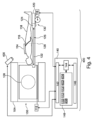
図1は、医用イメージングシステム100の一例を示す。医用イメージングシステム100は、磁気共鳴イメージングシステム102を含む。磁気共鳴イメージングシステム102は、磁石104を含む。磁石104は、それを貫通するボア106を有する超電導円筒型の磁石である。異なる種類の磁石の使用も可能である。例えば、分割円筒磁石といわゆるオープン磁石の両方を使用することも可能である。分割円筒磁石は、クライオスタットが磁石のアイソプレーンへのアクセスを可能にするために2つのセクションに分割されていることを除いて、標準的な円筒磁石と同様であり、このような磁石は、例えば、荷電粒子ビーム治療と併せて使用される。オープン磁石は、被験者を受け入れるのに十分な大きさの間隔を有する2つのマグネット部分を上下に有し、2つの部分の構成はヘルムホルツコイルのそれに類似している。オープン磁石は、被験者があまり閉じ込められないため、人気がある。円筒磁石のクライオスタットの内部には、超電導コイルの集合体がある。円筒磁石104のボア106内には、磁気共鳴イメージングを実行するのに十分な強さ及び均一性を有するイメージングゾーン108がある。関心領域109がイメージングゾーン108内に示されている。取得される磁気共鳴データは、典型的には、関心領域について取得される。被験者118は、被験者118の少なくとも一部がイメージングゾーン108及び関心領域109内にあるように、被験者支持体120によって支持されているように示されている。
FIG. 1 shows an example of a
磁石のボア106内には、磁場勾配コイル110のセットも存在し、これは、磁石104のイメージングゾーン108内の磁気スピンを空間的に符号化するための予備的な磁気共鳴データの取得のために使用される。磁場勾配コイル110は磁場勾配コイル電源112に接続される。磁場勾配コイル110は、代表的なものであることが意図されている。典型的には、磁場勾配コイル110は、3つの直交する空間方向において空間的に符号化するための3つの別々のセットのコイルを含む。磁場勾配電源は、磁場勾配コイルに電流を供給する。磁場勾配コイル110に供給される電流は、時間の関数として制御され、ランプ状にされてもパルス状にされてもよい。
Also present within the magnet bore 106 is a set of magnetic field gradient coils 110 for acquiring preliminary magnetic resonance data to spatially encode magnetic spins within the
イメージングゾーン108に隣接して、イメージングゾーン108内の磁気スピンの配向を操作し、またイメージングゾーン108内のスピンからの無線送信を受信するための磁気共鳴イメージングアンテナ114がある。無線周波数アンテナは、複数のコイル要素を含む。無線周波数アンテナは、チャネル、コイル、又はアンテナと呼ばれることもある。磁気共鳴イメージングアンテナ114は、無線周波数システム116に接続される。場合によっては、無線周波数システム116は、磁気共鳴イメージングアンテナ114と接続するトランシーバである。他の場合には、無線周波数システム116は、磁気共鳴イメージングコイル上の前置増幅器、送信器、及び/又は受信器を制御及び/又は通信するシステムである。
Adjacent to the
磁気共鳴イメージングアンテナ114及び無線周波数システム116は、別個の送信コイル及び受信コイル、並びに別個の送信器及び受信器と置き換えてもよい。磁気共鳴イメージングアンテナ114及び無線周波数システム116は、代表的なものであることが理解される。磁気共鳴イメージングアンテナ114及び無線周波数システム116は、複数の受信/送信チャネルを有する。例えば、SENSEのような平行イメージング技術が実行される場合、磁気共鳴イメージングアンテナ114は、複数のコイル要素を有することができる。
Magnetic
被験者支持体120は、イメージングゾーン108内で被験者118を少なくとも部分的に支持する。被験者支持体120は、引き出されているか、又は磁石104のボア106内にまだ配置されていないものとして示されている。被験者支持体120は、遠隔制御可能なアクチュエータ122によって経路126に沿って動かすことができるアンテナコネクタ124を含む。矢印122は、アンテナコネクタ124を移動させることができるアクチュエータ及び経路126の両方を示す。磁気共鳴イメージングアンテナ114は、アンテナコネクタ124に接続可能なケーブル115を有する。この例では、ケーブル115は比較的短いので、アンテナコネクタ124をコネクタ位置の物理的位置128に最適に移動させる必要がある。この例では、トランシーバ116は、ケーブル管理システム130を使用してアンテナコネクタ124に接続される。異なる例では、ケーブル115は、異なる形態をとることができる。ある形態では、ケーブル115は無線周波数ケーブルである。他の例では、ケーブルは、光又は他のデジタル伝送要素を含むこともできる。さらに他の例では、ケーブル115は、無線接続に置き換えられてもよい。
無線周波数システム116及び勾配コントローラ112は、コンピュータシステム140のハードウェアインターフェース142に接続されているように示されている。コンピュータシステムはさらに、ハードウェアインターフェース142、メモリ148、及びユーザーインターフェース146と通信するプロセッサ144を含む。メモリ148は、プロセッサ144にアクセス可能な任意の組み合わせのメモリであってもよい。これには、メインメモリ、キャッシュメモリなどのものや、フラッシュRAM、ハードドライブ、又はその他の記憶装置などの不揮発性メモリも含まれる。いくつかの実施例では、メモリ148は、非一時的コンピュータ可読媒体であると考えることができる。
メモリ148は、機械実行可能命令150を含むものとして示されている。機械実行可能命令150は、プロセッサ144が医療機器100の動作及び機能を制御することを可能にする。機械実行可能命令150はまた、プロセッサ144が様々なデータ分析及び計算機能を実行することを可能にしてもよい。コンピュータメモリ148は、パルスシーケンスコマンドを含むこともできる。パルスシーケンスコマンドは、磁気共鳴イメージングプロトコルに従って、被験者118から磁気共鳴イメージングデータを取得するように、磁気共鳴イメージングシステム102を制御することができる。
メモリ148はさらに、コンピュータシステム140によって受け取られたコネクタ位置154を含むものとして示されている。コネクタ位置154は物理的位置128に対応する。次いで、プロセッサ144は、アクチュエータ122を制御して、アンテナコネクタ124を物理的位置128に移動させることができる。
図2は、医療機器100のさらなる図を示す。図2に示される図において、アクチュエータ122は、アンテナコネクタ124をコネクタ位置128に移動させるために使用されている。これにより、アンテナコネクタ124は、ケーブル115をアンテナコネクタ124に接続することができるほど十分に接近している。これで、磁気共鳴イメージングアンテナ114を使用することができる。
FIG. 2 shows a further view of the
図3は、医用イメージングシステム100のさらなる図を示す。この例では、被験者支持体120は、磁石104のボア106内に移動されている。ここで、被験者118は、磁気共鳴イメージングアンテナ114がイメージングゾーン108内にあり、関心領域300をイメージングできるように配置される。
FIG. 3 shows a further diagram of the
コンピュータメモリ148は、さらに、パルスシーケンスコマンド152で磁気共鳴イメージングシステム102を制御することによってイメージングゾーン300から取得された磁気共鳴イメージングデータ302を含むものとして示される。メモリ148はさらに、磁気共鳴イメージングデータ302から再構成された磁気共鳴画像304を含むものとして示されている。
図3Aは、図1、図2及び図3に示される医用イメージングシステム100を操作する方法を示すフローチャートを示す。まず、ステップ350において、コネクタ位置154が受信される。次に、ステップ352において、遠隔制御可能アクチュエータ122が制御されて、コネクタ124をコネクタ位置128に移動させる。
FIG. 3A shows a flowchart illustrating a method of operating the
図1、図2及び図3では、コネクタ位置154はメモリ148内にあるものとして示されている。図4~図8は、コネクタ位置154が、操作者から手動で受信されるか、又は自動的に取得されるように、医用イメージングシステム100に対して行われてよい追加を示す。図4~図8に示す例を、図1~図3に示す例と自由に組み合わせることができる。
In FIGS. 1, 2, and 3,
図4は、医用イメージングシステム400のさらなる例を示す。図4の医用イメージングシステム400は、追加のカメラシステム400があることを除いて、図1~図3の医用イメージングシステム100と同様である。カメラシステム400は、1つ又は複数のカメラによって形成することができる。1つ又は複数のカメラは、磁石104のボア106の内側及び/又は外側にある。カメラシステムは、被験者支持体120の表面に向けられ、かつ、その表面をイメージングすることができる。
FIG. 4 shows a further example of a
メモリ148は、カメラシステム400を使用して取得されたカメラ画像402を含むものとしてさらに示される。画像402は、被験者118上の磁気共鳴イメージングアンテナ114の画像を示す。メモリ148は、アンテナ位置モデル404を含むものとしてさらに示される。メモリ148は、アンテナ位置モデル404のカメラ画像402に対する位置合わせ406を含むものとしてさらに示される。位置合わせ406は、磁気共鳴イメージングアンテナ114の位置を知ることと等価である。次に、位置合わせ406を使用して、コネクタ位置154を計算することができる。
コネクタ位置154は、例えば、アンテナ位置モデル404の一部であってもよく、又は、コネクタ位置154の位置を推測又は計算するために使用することができるルックアップテーブル又は他のデータがあってもよい。図4の医用イメージングシステム400は、磁気共鳴イメージングアンテナ114の位置を自動的に検出し、アンテナコネクタ124を適切な位置に移動させることができる。
図5は、医用イメージングシステム500のさらなる例を示す。図5の医用イメージングシステム500は、図4に示したものと同様である。医用イメージングシステム500は、依然としてカメラシステム400を含む。しかしながら、図5に指摘されているように、磁気共鳴イメージングアンテナは、まだ、被験者118上に配置されていない。メモリ148はさらに、カメラ画像402を含むものとして示されている。しかし、この例では、カメラ画像402は、被験者支持体120上に静止している被験者118の画像のみを含む。
FIG. 5 shows a further example of a
メモリ148はさらに、被験者モデル500を含むものとして示されている。メモリ148はさらに、カメラ画像402に対する被験者モデル500の位置合わせ502を含むものとして示されている。これは、被験者118の位置を示すことに相当する。次に、位置合わせ502を使用してコネクタ位置154を計算することができる。メモリ148はさらに、任意選択の関心MRI領域選択504を含むものとして示されている。これは、例えば、被験者モデル500に対する関心領域である。次に、これを使用して実際の被験者118内でイメージングされるべき所望の関心領域の位置を特定することができる。関心MRI領域選択504及び位置合わせ502はまた、コネクタ位置154を計算するために使用される。
図6は、医用イメージングシステム600のさらなる例を示す。図6に示される例は、図1~図3に示されるものと同様である。図6の医療機器600は、近距離無線通信、即ち、NFC検出器606をさらに含むものとして示されている。磁気共鳴イメージングアンテナ114は、NFC信号608を出すNFC送信器又はトランシーバを含む。NFC信号608の放出は、NFC検出器606がNFC信号610を受信し、アンテナ位置を決定することを可能にする。
FIG. 6 shows a further example of a
アンテナ位置の決定は、プロセッサ144がコネクタ位置154を計算することを可能にする。例えば、メモリ148は、受信されたNFC信号610を含むことができる。NFC検出器606は、実際には、複数のNFC検出器を含み、磁気共鳴イメージングアンテナ114の位置の三角測量を可能にする。あるいは、NFC検出器606は、アンテナコネクタ124上に取り付けられてもよく、アンテナ114の位置は、アンテナコネクタ124が経路126に沿って移動するときに、NFC信号608がどのように変化するかに注目することによって学習されてもよい。
Determining the antenna position allows
図7は、図1~図3に示される医療機器100に一体化されうる被験者支持体120の一例を示す。被験者118は、被験者支持体120上に横たわっているものとして示される。アンテナコネクタ124は、可視であり、経路126に沿って移動することができる。経路126と平行に、ボタン700の線形アレイがある。オペレーターはボタンの1つを押すことができ、これをコネクタ位置154として記録することができる。
FIG. 7 shows an example of a
図8は、図1~図3の医療機器100に一体化されうる被験者支持体120のさらなる例を示す。図8の例は、ボタンの線形アレイが1つ又は複数のタッチセンサ800と置き換えられていることを除いて、図7の例と同様である。オペレーターは、タッチセンサ800上の位置にタッチするだけでよく、これは、コネクタ位置154として登録されてもよい。
FIG. 8 shows a further example of a
図9、図10、及び図11は、磁気共鳴イメージングアンテナ114がアンテナコネクタ124に接続することができる様々な方法を示す。図9、図10、及び図11は、コネクタ位置154がどのように決定されるかは図示していない。したがって、図9、図10、及び図11は、それぞれ、図1、図2、図3、図4、図5、図6、図7、及び図8と組み合わせて、異なる実施形態を組み合わせることができる。
9, 10, and 11 illustrate various ways in which magnetic
図9は、医療機器900のさらなる例を示す。医療機器900は、アンテナコネクタ124に一体化されたRFシステムトランシーバ902を含むものとして示されている。磁気共鳴イメージングアンテナ114は、アンテナトランシーバ904を含むものとして示される。RFシステムトランシーバ902及びアンテナトランシーバ904は、無線接続906を形成する。したがって、磁気共鳴イメージングアンテナ114は、磁気共鳴イメージングデータの取得中には、何ら配線接続を有していない。
FIG. 9 shows a further example of a
このようなシステムの性能は、RFシステムトランシーバ902が配置される位置に大きく依存することがある。磁気共鳴イメージングアンテナ114の位置が決定されると、モデルを使用してコネクタ位置154を選択することができる。磁気共鳴イメージングアンテナの位置は、例えば、アンテナコネクタ124を移動させ、無線接続906の信号強度の変化に注目することによって実行することができ、あるいは、前の図のうちの1つに示された手段のうちの任意の1つによって実行することができる。
The performance of such systems can be highly dependent on the location where the
図10は、医療機器1000のさらなる例を示す。医療機器1000は、磁気共鳴イメージングアンテナ114が、磁気共鳴イメージングアンテナ114がケーブル115の端部にアンテナプラグ1002を含むように修正されている点を除き、図1、図2、図3、図4、図5、図6、図7、及び図8に例示されている例と同様である。アンテナプラグ1002は、コイル電子機器を含む。前置増幅器、デジタイザ、及び他の能動構成要素は、磁気共鳴イメージングアンテナから移動され、アンテナプラグ1002内に配置される。これは、磁気共鳴イメージングアンテナをより軽量にし、例えば、放射線に対してより透過性にする利点を有する。これは、ケーブル長115が短く保たれているために可能である。次いで、アンテナコネクタ124は、アンテナプラグ1002への電力と、デジタル接続とを提供する。この例は、アンテナプラグ124が、多くの異なる磁気共鳴イメージングアンテナ114とインターフェースすることができる標準的なインターフェースでデザインすることができるので、有益でありうる。
FIG. 10 shows a further example of a
図11は、医療機器1100のさらなる例を示す。図11の医療機器1100は、コイル電子機器1102を含むアンテナコネクタ124を図示する。コイル電子機器は、磁気共鳴イメージングアンテナ114及び/又は様々なデジタイザ及び他の能動電子機器のための前置増幅器を含むことができる。これにより、磁気共鳴イメージングアンテナ114は、より軽量であり、その表面上の構成要素がより少なくなることが可能になりうる。図11の特徴は、さらに、図1、図2、図3、図5、図6、図7、及び図8に図示した例と組み合わせることができる。
FIG. 11 shows a further example of a
図12は、医療機器1200のさらなる例を示す。この例では、医療機器1200は、放射線治療システム1202をさらに含む。図12に示される例は、放射線治療システム1202と組み合わされた図11の例の組み合わせである。図11の被験者支持体120を図12に示す。
FIG. 12 shows a further example of a
この特定の例では、放射線治療システムは線形加速器(LINAC)である。しかしながら、LINACの描写は、代表的なものであることが意図される。磁気共鳴イメージングによって誘導することができる他のタイプの放射線治療システムを代用することができる。放射線治療システム1202は、ガントリ1206及び放射線治療源1208を含む。ガントリ1206は、ガントリ回転軸1240の周りに放射線治療源1208を回転させるためのものである。放射線治療源1208に隣接してコリメータ1210がある。
In this particular example, the radiation therapy system is a linear accelerator (LINAC). However, the depiction of LINAC is intended to be representative. Other types of radiotherapy systems that can be guided by magnetic resonance imaging can be substituted.
本実施形態に示す磁石104は、標準的な円筒超電導磁石である。磁石1045は、その内部に超電導コイル1216を有するクライオスタット1214を有する。また、クライオスタット内には超電導シールドコイル1218がある。磁石104は、ボア106を有する。
The
磁石104のボア106内で、被験者支持体120は、被験者118を支持する。被験者支持体134は、機械的位置決めシステムによって位置決めされる。被験者118内には、ターゲットゾーン1238がある。ガントリ回転軸1240は、この特定の実施形態では、磁石104の円筒軸と同軸である。被験者支持体120は、ターゲットゾーン1238がガントリ回転軸1240上にあるように配置されている。放射線源1208は、コリメータ1210を通過してターゲットゾーン1238を通過する放射線ビーム1242を生成するものとして示される。放射線源1208が軸1240を中心に回転されると、ターゲットゾーン1238は、常に、放射線ビーム1242によって標的とされることになる。放射線ビーム1242は、磁石104のクライオスタット1214を通過する。磁場勾配コイル110は、磁場勾配コイルを2つの部分に分離するギャップを有する。存在する場合、このギャップは、磁場勾配コイル110による放射線ビーム1242の減衰を低減する。
Within the
磁石104のボア116内には、無線周波数システム116に接続された任意選択のボディコイル1220があることが分かる。放射線治療システム1202は、ハードウェアインターフェース142に追加的に接続されるものとして示されている。
It can be seen that within the
コンピュータメモリ150は、プロセッサ148が医療機器100の様々な構成要素の動作及び機能を制御することを可能にする機械実行可能命令152を含むものとして示されている。コンピュータメモリ150はさらに、プロセッサ148が磁気共鳴イメージングシステム104を制御して磁気共鳴データを取得することを可能にするパルスシーケンスコマンド154を含むものとして示されている。メモリ148はさらに、放射線治療命令1250を含むものとして示されている。放射線治療命令1250を使用して、計算されたビーム経路1252を決定することができる。計算されたビーム経路1252を使用して、ベクトル位置154を修正することができる。図12から、アンテナコネクタ124は、ビーム経路1242から安全に外れていることが分かる。コネクタ位置154を予め設定し、次いで、計算されたビーム経路1252でそれを修正することによって、放射線治療の質を向上させることができる。
コンピュータメモリ148はさらに、磁気共鳴データ302から再構成された磁気共鳴画像304を含むものとして示されている。磁気共鳴画像304は、例えば、放射線治療システム1202を使用する放射線治療を誘導するために使用される。
図13は、図12の医療機器1200を操作する方法を示すフローチャートを示す。まず、ステップ350において、コネクタ位置154が受信される。次に、ステップ1300において、放射線治療命令1250が受信される。次いで、ステップ1302において、ビーム経路1252が決定される。次に、ステップ1304にいて、コネクタ位置154が、ビーム経路1252を回避するように修正される。次いで、ステップ352において、遠隔制御可能アクチュエータが制御されて、アンテナコネクタ124を経路に沿ってコネクタ位置154に移動させる。最後に、ステップ1306において、放射線治療システム1202が放射線治療命令1250で制御されて、放射線治療システム1202を使用してターゲットゾーン1238が照射される。図13には示されていないが、磁気共鳴イメージングデータ302を取得し、これを使用して、放射線治療を誘導するために使用することができる磁気共鳴画像304を作成することもできる。
FIG. 13 shows a flowchart illustrating a method of operating the
一般的なMRシステムのセットアップでは、RFコイルは、コネクタを介してMRスキャナのRFインターフェースにRF/供給ケーブルで接続されている。RFコイルの接続点は、患者ベッド上に固定されている。コイルケーブルの長さが限られているため、RFコイルの位置決めの自由度は限られており、臨床作業の流れに最適ではない。コイルのRFケーブルは、RFの安全性の理由から短くなっている。 In a typical MR system setup, the RF coil is connected to the MR scanner's RF interface via a connector with an RF/supply cable. The connection point of the RF coil is fixed on the patient bed. Due to the limited length of the coil cable, the flexibility in positioning the RF coil is limited and is not optimal for clinical work flows. The coil's RF cable is short for RF safety reasons.
完全に無線のRFコイルは、RFコイルの自由な位置決めを可能にするであろう。この場合、多くのデジタルハードウェア及び電力伝送又はバッテリを追加的に一体化する必要があり、これはコイルを厚くし、比較的重くする。実施例は、薄く、位置決めの自由度がより高い軽量コイルを提供しうる。臨床状況では、自由に配置することができる薄くて軽量のRFコイルを有することが有益でありうる。 A completely wireless RF coil would allow free positioning of the RF coil. In this case, a lot of digital hardware and power transmission or batteries need to be additionally integrated, which makes the coil thick and relatively heavy. Embodiments may provide thin, lightweight coils with greater positioning flexibility. In clinical situations, it can be beneficial to have thin and lightweight RF coils that can be freely placed.
実施例は、長いケーブルや、ケーブルベッドの端部における固定コネクタの制約を排除することができる。また、長いケーブルを避けることで安全性を高めることができる。 Embodiments can eliminate the limitations of long cables and fixed connectors at the ends of the cable bed. Safety can also be increased by avoiding long cables.
実施例は、患者ベッド/支持体に一体化されたRF安全ケーブル管理を使用する可動コネクタ(アンテナコネクタ)を使用することができる。提案されたシステムは、患者ベッドに沿って移動する専用コネクタからなる。 Embodiments may use a movable connector (antenna connector) that uses RF safety cable management integrated into the patient bed/support. The proposed system consists of a dedicated connector that moves along the patient bed.
コイルが患者に配置されると、比較的短いケーブルが可動プラグに接続される。 Once the coil is placed on the patient, a relatively short cable is connected to the movable plug.
いくつかの実施例では、プラグは、光学/NFC検出を介して、対応するコイルに自動的に移動される。 In some embodiments, the plug is automatically moved to the corresponding coil via optical/NFC detection.
実施例は、RFコイルの接続のより多くの自由度を可能にし、RF安全性を増大させる。 Embodiments allow more flexibility in connecting RF coils and increase RF safety.
図14は、医療機器1400のさらなる例を示す。医療機器は、磁石104及び被験者支持体120を有するMRIシステム102を有するものとして示されている。被験者118は、被験者支持体120上に横たわっているものとして示されている。アンテナコネクタ124に接続する2本のケーブル115を有する磁気共鳴イメージングアンテナ114がある。両方のアンテナコネクタ124は、被験者118の両側の経路126上を移動することができる。システムは、コンピュータシステム140によって制御され、ユーザーインターフェース146上にアプリがある。コンピュータシステム140は、プロセッサ及び制御機能を提供する。
FIG. 14 shows a further example of a
図14は、医療機器の可能な例を示しており、移動プラグが、患者ベッドの左右に配置され、スライドレールシステムに沿って移動する。可動プラグ/コネクタは、患者ベッド内/下に配置された可撓性ケーブルに電気的に接続される。トラベラーインターフェース(ユーザーインターフェース)146は、無線/光接続である。 Figure 14 shows a possible example of a medical device, in which moving plugs are placed on the left and right sides of the patient bed and move along a slide rail system. The movable plug/connector is electrically connected to a flexible cable located in/under the patient bed. Traveler interface (user interface) 146 is a wireless/optical connection.
可動コネクタは、スライドシステム上を移動する場合がある。可撓性接続ケーブルは、患者ベッド/支持体に一体化される。可撓性ケーブルは、光ケーブルとすることができるので、RFトラップを必要としない。 The movable connector may move on a sliding system. A flexible connecting cable is integrated into the patient bed/support. The flexible cable can be an optical cable and therefore does not require an RF trap.
異なる実施形態は、無線接続トラベラープラグ(アンテナコネクタ)である。ここでコイルは接続されているが、可動コネクタには無線トランシーバデバイスが含まれているため、供給ケーブルのみが必要である。 A different embodiment is a wireless connection traveler plug (antenna connector). The coils are now connected, but only the supply cable is required since the movable connector contains a wireless transceiver device.
本発明は、図面及び前述の説明において詳細に図示及び説明されてきたが、このような図示及び説明は、例示的であり、限定的ではないと考えられるべきであり、本発明は、開示された実施形態に限定されない。 Although the invention has been illustrated and described in detail in the drawings and foregoing description, such illustration and description are to be considered illustrative and not restrictive, and the invention The present invention is not limited to the embodiments described above.
開示された実施形態に対する他の変形は、図面、開示、及び添付の特許請求の範囲の検討から、特許請求された発明を実施する際に当業者によって理解され、実施されることができる。特許請求の範囲において、単語「含む」は、他の要素又はステップを排除するものではなく、単数形は、複数を排除するものではない。単一のプロセッサ又は他のユニットが、特許請求の範囲に列挙されるいくつかのアイテムの機能を満たすことができる。特定の手段が相互に異なる従属請求項に記載されているという単なる事実は、これらの手段の組み合わせが有利に使用されることができないことを示すものではない。コンピュータプログラムは、他のハードウェアと一緒に、又はその一部として供給される光記憶媒体又はソリッドステート媒体などの適切な媒体上に記憶/配布することができるが、インターネット又は他の有線もしくは無線電気通信システムなどを介して、他の形態で配布することもできる。特許請求の範囲におけるいかなる参照符号も、範囲を限定するものとして解釈されるべきではない。 Other variations to the disclosed embodiments will be understood and can be practiced by those skilled in the art from a study of the drawings, the disclosure, and the appended claims in practicing the claimed invention. In the claims, the word "comprising" does not exclude other elements or steps, and the singular does not exclude the plural. A single processor or other unit may fulfill the functions of several items recited in the claims. The mere fact that certain measures are recited in mutually different dependent claims does not indicate that a combination of these measures cannot be used to advantage. The computer program may be stored/distributed on a suitable medium, such as an optical storage medium or a solid state medium, supplied with or as part of other hardware, but not connected to the Internet or other wired or wireless It may also be distributed in other forms, such as via telecommunications systems. Any reference signs in the claims shall not be construed as limiting the scope.
100 医用イメージングシステム
102 磁気共鳴イメージングシステム
104 磁石
106 磁石のボア
108 イメージングゾーン
110 磁場勾配コイル
112 磁場勾配コイル電源
114 磁気共鳴イメージングアンテナ
115 ケーブル
116 トランシーバ
118 被験者
120 被験者支持体
122 遠隔制御可能なアクチュエータ
124 アンテナコネクタ
126 経路
128 コネクタ位置の物理的位置
130 ケーブルマネジメントシステム
140 コンピュータシステム
142 ハードウェアインターフェース
144 プロセッサ
146 ユーザーインターフェース
148 コンピュータメモリ
150 機械実行可能命令
152 パルスシーケンスコマンド
154 コネクタ位置
300 関心領域
302 磁気共鳴イメージングデータ
304 磁気共鳴画像
350 コネクタ位置を受信する
352 遠隔制御可能アクチュエータを制御して、アンテナコネクタを経路に沿ってコネクタ位置に移動させる
400 カメラシステム
402 カメラ画像
404 アンテナ位置モデル
406 アンテナ位置モデルのカメラ画像に対する位置合わせ
500 被験者モデル
502 被験者モデルのカメラ画像に対する位置合わせ
504 関心MRI領域選択
600 医療機器
606 NFC検出器
608 NFC信号
610 受信NFC信号
700 ボタンの線形アレイ
800 タッチセンサ
900 医用イメージングシステム
902 RFシステムトランスシーバ
904 アンテナトランシーバ
906 ワイヤレス接続
1000 医療機器
1002 コイル電子機器付きアンテナプラグ
1100 医療機器
1102 コイル電子機器
1200 医療機器
1202 外部ビーム放射線治療システム
1206 ガントリ
1208 放射線治療源
1210 コリメータ
1214 クライオスタット
1216 超電導コイル
1218 超電導シールドコイル
1220 ボディコイル
1238 ターゲットゾーン
1240 ガントリ回転軸
1242 放射ビーム経路
1250 放射線治療命令
1252 計算されたビーム経路
1300 ターゲットゾーンを照射するように放射線治療システムを制御する放射線治療命令を受信する
1302 放射線治療命令を使用してビーム経路を決定する
1304 ビーム経路を避けるためにコネクタ位置を修正する
1306 放射線治療命令を使用してターゲットゾーンを照射するように放射線治療システムを制御する
1400 医療機器
100 Medical Imaging System 102 Magnetic Resonance Imaging System 104 Magnet 106 Magnet Bore 108 Imaging Zone 110 Magnetic Field Gradient Coil 112 Magnetic Field Gradient Coil Power Supply 114 Magnetic Resonance Imaging Antenna 115 Cable 116 Transceiver 118 Subject 120 Subject Support 122 Remotely Controllable Actuator 124 Antenna connector 126 pathway 128 physical location of connector location 130 cable management system 140 computer system 142 hardware interface 144 processor 146 user interface 148 computer memory 150 machine executable instructions 152 pulse sequence commands 154 connector location 300 region of interest 302 magnetic resonance imaging data 304 Magnetic Resonance Image 350 Receive Connector Position 352 Control Remotely Controllable Actuator to Move Antenna Connector Along Path to Connector Position 400 Camera System 402 Camera Image 404 Antenna Position Model 406 Position of the Antenna Position Model with respect to the Camera Image alignment 500 subject model 502 alignment of subject model to camera image 504 MRI region of interest selection 600 medical device 606 NFC detector 608 NFC signal 610 received NFC signal 700 linear array of buttons 800 touch sensor 900 medical imaging system 902 RF system transceiver 904 Antenna transceiver 906 Wireless connection 1000 Medical device 1002 Antenna plug with coil electronics 1100 Medical device 1102 Coil electronics 1200 Medical device 1202 External beam radiotherapy system 1206 Gantry 1208 Radiotherapy source 1210 Collimator 1214 Cryostat 1216 Superconducting coil 1218 Superconducting shield coil 1220 Body coil 1238 target zone 1240 gantry rotation axis 1242 radiation beam path 1250 radiation treatment commands 1252 calculated beam path 1300 receiving radiation treatment commands 1302 controlling the radiation treatment system to irradiate the target zone using the radiation treatment commands determining 1304 the beam path; modifying the connector position to avoid the beam path 1306; controlling the radiation therapy system to irradiate the target zone using radiation therapy instructions 1400; medical device;
Claims (16)
磁気共鳴イメージングデータを取得するために無線周波数信号を送受信する無線周波数システムであって、磁気共鳴イメージングアンテナに接続する、無線周波数システムと、
前記磁気共鳴イメージングシステムのイメージングゾーン内の被験者の少なくとも一部を支持する被験者支持体であって、前記被験者支持体は、前記磁気共鳴イメージングアンテナに接続するアンテナコネクタを含み、前記無線周波数システムは、前記アンテナコネクタを介して前記磁気共鳴イメージングアンテナに接続し、前記被験者支持体は、前記アンテナコネクタを、経路に沿ったコネクタ位置に平行移動させる制御可能なアクチュエータを含む、被験者支持体と、
前記被験者支持体を含むカメラ画像を提供するカメラと、
機械実行可能命令を含むメモリと、
前記磁気共鳴イメージングシステムを制御するためのプロセッサと、を含み、
前記機械実行可能命令の実行は、前記プロセッサに、
前記カメラ画像を使用して前記コネクタ位置を決定させ、前記アンテナコネクタを前記経路に沿って前記コネクタ位置に移動させるために前記制御可能なアクチュエータを制御させる、医療機器。 A medical device comprising a magnetic resonance imaging system, the medical device comprising:
a radio frequency system for transmitting and receiving radio frequency signals to obtain magnetic resonance imaging data, the radio frequency system being coupled to a magnetic resonance imaging antenna;
a subject support supporting at least a portion of a subject within an imaging zone of the magnetic resonance imaging system, the subject support including an antenna connector connecting to the magnetic resonance imaging antenna, the radio frequency system comprising: a subject support connected to the magnetic resonance imaging antenna via the antenna connector, the subject support including a controllable actuator that translates the antenna connector to a connector position along a path;
a camera that provides a camera image including the subject support;
memory containing machine-executable instructions;
a processor for controlling the magnetic resonance imaging system;
Execution of the machine-executable instructions causes the processor to:
The medical device uses the camera image to determine the connector position and controls the controllable actuator to move the antenna connector along the path to the connector position.
磁気共鳴イメージングデータを取得するために無線周波数信号を送受信する無線周波数システムであって、磁気共鳴イメージングアンテナに接続する、無線周波数システムと、
前記磁気共鳴イメージングシステムのイメージングゾーン内の被験者の少なくとも一部を支持する被験者支持体であって、前記被験者支持体は、前記磁気共鳴イメージングアンテナに接続するアンテナコネクタを含み、前記無線周波数システムは、前記アンテナコネクタを介して前記磁気共鳴イメージングアンテナに接続し、前記被験者支持体は、前記アンテナコネクタを、経路に沿ったコネクタ位置に平行移動させる制御可能なアクチュエータを含み、前記被験者支持体は、前記経路に沿って分布する線形位置セレクタを含む、被験者支持体と、
機械実行可能命令を含むメモリと、
前記磁気共鳴イメージングシステムを制御するためのプロセッサと、を含み、
前記機械実行可能命令の実行は、前記プロセッサに、
非接触手段によって前記コネクタ位置を決定させ、前記アンテナコネクタを前記経路に沿って前記コネクタ位置に移動させるために前記制御可能なアクチュエータを制御させ、前記線形位置セレクタから選択された位置を受信させ、
前記コネクタ位置は、前記選択された位置を使用して少なくとも部分的に決定され、前記線形位置セレクタは、ボタンの線形アレイ及びタッチセンサのうちのいずれか1つである、医療機器。 A medical device comprising a magnetic resonance imaging system, the medical device comprising:
a radio frequency system for transmitting and receiving radio frequency signals to obtain magnetic resonance imaging data, the radio frequency system being coupled to a magnetic resonance imaging antenna;
a subject support supporting at least a portion of a subject within an imaging zone of the magnetic resonance imaging system, the subject support including an antenna connector connecting to the magnetic resonance imaging antenna, the radio frequency system comprising: connected to the magnetic resonance imaging antenna via the antenna connector, the subject support includes a controllable actuator that translates the antenna connector to a connector position along a path ; a subject support including linear position selectors distributed along the path;
memory containing machine-executable instructions;
a processor for controlling the magnetic resonance imaging system;
Execution of the machine-executable instructions causes the processor to:
determining the connector position by non-contact means, controlling the controllable actuator to move the antenna connector along the path to the connector position, and receiving a selected position from the linear position selector;
The medical device, wherein the connector position is determined at least in part using the selected position, and the linear position selector is any one of a linear array of buttons and a touch sensor.
磁気共鳴イメージングデータを取得するために無線周波数信号を送受信する無線周波数システムであって、磁気共鳴イメージングアンテナに接続する、無線周波数システムと、
前記磁気共鳴イメージングシステムのイメージングゾーン内の被験者の少なくとも一部を支持する被験者支持体であって、前記被験者支持体は、前記磁気共鳴イメージングアンテナに接続するアンテナコネクタを含み、前記無線周波数システムは、前記アンテナコネクタを介して前記磁気共鳴イメージングアンテナに接続し、前記被験者支持体は、前記アンテナコネクタを、経路に沿ったコネクタ位置に平行移動させる制御可能なアクチュエータを含む、被験者支持体と、
機械実行可能命令を含むメモリと、
前記磁気共鳴イメージングシステムを制御するためのプロセッサと、
ターゲットゾーンを照射する放射線治療システムと、を含み、
前記ターゲットゾーンは、前記イメージングゾーン内にあり、
前記機械実行可能命令の実行は、前記プロセッサに、
非接触手段によって前記コネクタ位置を決定させ、前記アンテナコネクタを前記経路に沿って前記コネクタ位置に移動させるために前記制御可能なアクチュエータを制御させ、
前記ターゲットゾーンを照射するように前記放射線治療システムを制御する放射線治療命令を受信させ、
前記放射線治療命令を使用してビーム経路を決定させ、
前記ビーム経路を回避するように前記コネクタ位置を修正させ、前記放射線治療命令を使用して前記ターゲットゾーンを照射するように前記放射線治療システムを制御させる、医療機器。 A medical device comprising a magnetic resonance imaging system, the medical device comprising:
a radio frequency system for transmitting and receiving radio frequency signals to obtain magnetic resonance imaging data, the radio frequency system being coupled to a magnetic resonance imaging antenna;
a subject support supporting at least a portion of a subject within an imaging zone of the magnetic resonance imaging system, the subject support including an antenna connector connecting to the magnetic resonance imaging antenna, the radio frequency system comprising: a subject support connected to the magnetic resonance imaging antenna via the antenna connector, the subject support including a controllable actuator that translates the antenna connector to a connector position along a path;
memory containing machine-executable instructions;
a processor for controlling the magnetic resonance imaging system;
a radiation therapy system for irradiating a target zone;
the target zone is within the imaging zone;
Execution of the machine -executable instructions causes the processor to:
determining the connector position by non-contact means and controlling the controllable actuator to move the antenna connector along the path to the connector position;
receiving radiation treatment instructions controlling the radiation treatment system to irradiate the target zone;
determining a beam path using the radiation treatment instructions;
A medical device that causes the connector position to be modified to avoid the beam path and controls the radiation therapy system to irradiate the target zone using the radiation therapy instructions.
磁気共鳴イメージングデータを取得するために無線周波数信号を送受信する無線周波数システムであって、磁気共鳴イメージングアンテナに接続する、無線周波数システムと、
前記磁気共鳴イメージングシステムのイメージングゾーン内の被験者の少なくとも一部を支持する被験者支持体であって、前記被験者支持体は、前記磁気共鳴イメージングアンテナに接続するアンテナコネクタを含み、前記無線周波数システムは、前記アンテナコネクタを介して前記磁気共鳴イメージングアンテナに接続し、前記被験者支持体は、前記アンテナコネクタを、経路に沿ったコネクタ位置に平行移動させる制御可能なアクチュエータを含み、前記被験者支持体は、前記磁気共鳴イメージングアンテナからNFC信号を受信するNFC検出器を含む、被験者支持体と、
機械実行可能命令を含むメモリと、
前記磁気共鳴イメージングシステムを制御するためのプロセッサと、を含み、
前記機械実行可能命令の実行は、前記プロセッサに、
前記NFC信号を少なくとも部分的に使用して前記コネクタ位置を決定させ、前記アンテナコネクタを前記経路に沿って前記コネクタ位置に移動させるために前記制御可能なアクチュエータを制御させる、医療機器。 A medical device comprising a magnetic resonance imaging system, the medical device comprising:
a radio frequency system for transmitting and receiving radio frequency signals to obtain magnetic resonance imaging data, the radio frequency system being coupled to a magnetic resonance imaging antenna;
a subject support supporting at least a portion of a subject within an imaging zone of the magnetic resonance imaging system, the subject support including an antenna connector connecting to the magnetic resonance imaging antenna, the radio frequency system comprising: connected to the magnetic resonance imaging antenna via the antenna connector, the subject support includes a controllable actuator that translates the antenna connector to a connector position along a path; a subject support including an NFC detector that receives an NFC signal from a magnetic resonance imaging antenna;
memory containing machine-executable instructions;
a processor for controlling the magnetic resonance imaging system;
Execution of the machine-executable instructions causes the processor to:
A medical device, wherein the NFC signal is at least partially used to determine the connector position and to control the controllable actuator to move the antenna connector along the path to the connector position .
前記RFシステムトランシーバを少なくとも部分的に使用して前記磁気共鳴イメージングアンテナの位置を決定させ、前記磁気共鳴イメージングアンテナの前記位置を使用して前記コネクタ位置を決定させる、請求項1から9のいずれか一項に記載の医療機器。 The antenna connector includes an RF system transceiver forming a wireless connection with the magnetic resonance imaging antenna, and execution of the machine-executable instructions further causes the processor to:
10. Any one of claims 1 to 9, wherein the RF system transceiver is at least partially used to determine the position of the magnetic resonance imaging antenna, and the position of the magnetic resonance imaging antenna is used to determine the connector position. The medical device described in paragraph 1.
前記カメラ画像を使用して前記コネクタ位置を決定するステップと、
前記アンテナコネクタを前記経路に沿って前記コネクタ位置に移動させるために前記制御可能なアクチュエータを制御するステップと、
を含む、方法。 A method of operating a medical device including a magnetic resonance imaging system, the medical device further including a radio frequency system for acquiring magnetic resonance imaging data from an imaging zone of the magnetic resonance imaging system, the radio frequency system comprising: transmitting and receiving radio frequency signals to acquire the magnetic resonance imaging data, the radio frequency system coupled to a magnetic resonance imaging antenna, and the medical device further supporting at least a portion of a subject within the imaging zone. a subject support, the subject support including an antenna connector connecting to the magnetic resonance imaging antenna, and the radio frequency system connecting to the magnetic resonance imaging antenna via the antenna connector; includes a controllable actuator that translates the antenna connector along a path to a connector position , the medical device further includes a camera that provides a camera image including the subject support, and the method includes:
determining the connector position using the camera image ;
controlling the controllable actuator to move the antenna connector along the path to the connector position;
including methods.
前記カメラ画像を使用して前記コネクタ位置を決定させ、
前記アンテナコネクタを前記経路に沿って前記コネクタ位置に移動させるために前記制御可能なアクチュエータを制御させる、
コンピュータプログラム。 A computer program product comprising machine-executable instructions for execution by a processor controlling a medical device including a magnetic resonance imaging system, the medical device further comprising: acquiring magnetic resonance imaging data from an imaging zone of the magnetic resonance imaging system. the medical device further comprises a radio frequency system that transmits and receives radio frequency signals to obtain the magnetic resonance imaging data, the radio frequency system is connected to a magnetic resonance imaging antenna, and the medical device further comprises: a subject support supporting at least a portion of a subject within the imaging zone, the subject support including an antenna connector connecting to the magnetic resonance imaging antenna; connected to the magnetic resonance imaging antenna, the subject support includes a controllable actuator that translates the antenna connector to a connector position along a path; the medical device further includes a camera image that includes the subject support; execution of the machine-executable instructions causes the processor to:
determining the connector position using the camera image ;
controlling the controllable actuator to move the antenna connector along the path to the connector position;
computer program.
Applications Claiming Priority (3)
| Application Number | Priority Date | Filing Date | Title |
|---|---|---|---|
| EP18166265.1 | 2018-04-09 | ||
| EP18166265.1A EP3553546A1 (en) | 2018-04-09 | 2018-04-09 | Automatic positioning of antenna connectors for magnetic resonance imaging |
| PCT/EP2019/058264 WO2019197215A1 (en) | 2018-04-09 | 2019-04-02 | Automatic positioning of antenna connectors for magnetic resonance imaging |
Publications (3)
| Publication Number | Publication Date |
|---|---|
| JP2021520871A JP2021520871A (en) | 2021-08-26 |
| JPWO2019197215A5 JPWO2019197215A5 (en) | 2022-04-08 |
| JP7453152B2 true JP7453152B2 (en) | 2024-03-19 |
Family
ID=62063262
Family Applications (1)
| Application Number | Title | Priority Date | Filing Date |
|---|---|---|---|
| JP2020555125A Active JP7453152B2 (en) | 2018-04-09 | 2019-04-02 | Automatic positioning of antenna connectors for magnetic resonance imaging |
Country Status (5)
| Country | Link |
|---|---|
| US (1) | US20210030306A1 (en) |
| EP (2) | EP3553546A1 (en) |
| JP (1) | JP7453152B2 (en) |
| CN (1) | CN112272776A (en) |
| WO (1) | WO2019197215A1 (en) |
Families Citing this family (3)
| Publication number | Priority date | Publication date | Assignee | Title |
|---|---|---|---|---|
| DE102019218285A1 (en) * | 2019-11-26 | 2021-05-27 | Siemens Healthcare Gmbh | Head coil arrangement with automatically positionable transmitter coil unit |
| USD951274S1 (en) | 2020-12-30 | 2022-05-10 | Varian Medical Systems, Inc. | Display screen of an electronic device with a graphical user interface |
| TWI776669B (en) * | 2021-09-07 | 2022-09-01 | 川升股份有限公司 | Phantom modeling system for evaluating antenna radiation efficiency after being affected by the human body |
Citations (3)
| Publication number | Priority date | Publication date | Assignee | Title |
|---|---|---|---|---|
| JP2007068984A (en) | 2005-08-10 | 2007-03-22 | Toshiba Corp | Magnetic resonance imaging apparatus, coil support unit, high-frequency coil unit, and method for controlling magnetic resonance imaging apparatus |
| JP2016524510A (en) | 2013-06-17 | 2016-08-18 | コーニンクレッカ フィリップス エヌ ヴェKoninklijke Philips N.V. | Magnetic resonance imaging subject support |
| WO2017077435A1 (en) | 2015-11-05 | 2017-05-11 | Koninklijke Philips N.V. | Mri system with automatic positioning of radio-frequency coil based upon wireless signal and method of operation thereof |
Family Cites Families (21)
| Publication number | Priority date | Publication date | Assignee | Title |
|---|---|---|---|---|
| DE3935082C1 (en) * | 1989-10-20 | 1991-01-31 | Siemens Ag, 1000 Berlin Und 8000 Muenchen, De | |
| JP4327311B2 (en) * | 1999-10-01 | 2009-09-09 | 東芝医用システムエンジニアリング株式会社 | RF coil device for MR imaging |
| US7570056B2 (en) * | 2005-08-10 | 2009-08-04 | Kabushiki Kaisha Toshiba | Magnetic resonance imaging apparatus |
| JP5238156B2 (en) * | 2005-11-02 | 2013-07-17 | 株式会社東芝 | Magnetic resonance imaging apparatus and high frequency coil selection method in the apparatus |
| DE102009004448B4 (en) * | 2009-01-13 | 2012-05-24 | Siemens Aktiengesellschaft | Coil position detection |
| US8467847B2 (en) * | 2010-09-08 | 2013-06-18 | Siemens Medical Solutions Usa, Inc. | Hybrid MR/PET scanner with patient table split cable feed |
| EP2745128A1 (en) * | 2011-09-07 | 2014-06-25 | Koninklijke Philips N.V. | Mr receive coil platform with selective engagement between receive coil and patient table top |
| JP6073612B2 (en) * | 2012-09-12 | 2017-02-01 | 東芝メディカルシステムズ株式会社 | Magnetic resonance imaging system |
| EP2872913B1 (en) * | 2012-09-18 | 2016-02-24 | Koninklijke Philips N.V. | Magnetic resonance guided linac |
| DE112013005114T5 (en) * | 2012-10-23 | 2015-09-10 | Koninklijke Philips N.V. | Specific Apsorption Rates Control for Magnetic Resonance (SAR) Imaging |
| EP2992349B1 (en) * | 2013-05-02 | 2021-02-24 | Koninklijke Philips N.V. | Detachable receiver block comprising an analog-digital converter for a family of local rf coils |
| KR101541291B1 (en) * | 2013-07-17 | 2015-08-03 | 삼성전자주식회사 | Magnetic resonance imaging apparatus and method for providing notification information by mri apparatus, and radio frequency coil and method for providing notification information by rf coil |
| CN203576502U (en) * | 2013-09-09 | 2014-05-07 | 皇家飞利浦有限公司 | Magnetic resonance patient bed with movable coil connector |
| US9517021B2 (en) * | 2013-09-23 | 2016-12-13 | Toshiba Medical Systems Corporation | Communicating between MRI control system and RF coils |
| CN106662626B (en) * | 2014-05-09 | 2019-07-16 | 皇家飞利浦有限公司 | The treatment system of the unit of position comprising MRI module and for determining RF coil |
| US10436869B2 (en) * | 2014-06-27 | 2019-10-08 | Koninklijke Philips N.V. | Positioning of a magnetic resonance imaging antenna within the homogeneous field zone |
| WO2016034364A1 (en) * | 2014-09-01 | 2016-03-10 | Koninklijke Philips N.V. | Magnetic resonance imaging receive coil with reduced radiation attenuation |
| KR20160049273A (en) * | 2014-10-27 | 2016-05-09 | 삼성전자주식회사 | Medical imaging apparatus |
| US10481228B2 (en) * | 2014-12-04 | 2019-11-19 | Koninklijke Philips N.V. | Light data communication link device for use in magnetic resonance examination systems |
| US9715304B2 (en) | 2015-06-30 | 2017-07-25 | Synaptics Incorporated | Regular via pattern for sensor-based input device |
| DE102016212043B4 (en) * | 2016-07-01 | 2018-03-01 | Siemens Healthcare Gmbh | Patient couch with flexible RF transmission power distribution for a magnetic resonance tomograph |
-
2018
- 2018-04-09 EP EP18166265.1A patent/EP3553546A1/en not_active Withdrawn
-
2019
- 2019-04-02 JP JP2020555125A patent/JP7453152B2/en active Active
- 2019-04-02 WO PCT/EP2019/058264 patent/WO2019197215A1/en unknown
- 2019-04-02 EP EP19713514.8A patent/EP3775951A1/en active Pending
- 2019-04-02 CN CN201980038918.6A patent/CN112272776A/en active Pending
- 2019-04-02 US US17/046,109 patent/US20210030306A1/en active Pending
Patent Citations (3)
| Publication number | Priority date | Publication date | Assignee | Title |
|---|---|---|---|---|
| JP2007068984A (en) | 2005-08-10 | 2007-03-22 | Toshiba Corp | Magnetic resonance imaging apparatus, coil support unit, high-frequency coil unit, and method for controlling magnetic resonance imaging apparatus |
| JP2016524510A (en) | 2013-06-17 | 2016-08-18 | コーニンクレッカ フィリップス エヌ ヴェKoninklijke Philips N.V. | Magnetic resonance imaging subject support |
| WO2017077435A1 (en) | 2015-11-05 | 2017-05-11 | Koninklijke Philips N.V. | Mri system with automatic positioning of radio-frequency coil based upon wireless signal and method of operation thereof |
Also Published As
| Publication number | Publication date |
|---|---|
| WO2019197215A1 (en) | 2019-10-17 |
| EP3775951A1 (en) | 2021-02-17 |
| US20210030306A1 (en) | 2021-02-04 |
| EP3553546A1 (en) | 2019-10-16 |
| CN112272776A (en) | 2021-01-26 |
| JP2021520871A (en) | 2021-08-26 |
Similar Documents
| Publication | Publication Date | Title |
|---|---|---|
| EP2872913B1 (en) | Magnetic resonance guided linac | |
| US10307616B2 (en) | Medical apparatus with a radiation therapy device and a radiation detection system | |
| JP6348902B2 (en) | Magnetic resonance induction therapy by interleave scanning | |
| CN105792894B (en) | Medical instrument for external beam radiotherapy and brachytherapy | |
| JP7453152B2 (en) | Automatic positioning of antenna connectors for magnetic resonance imaging | |
| CN105793721B (en) | Magnetic resonance imaging system using zero echo time pulse sequence | |
| CN106662626A (en) | A therapy system containing an mri module and means for determining the position of an rf coil | |
| EP3117230B1 (en) | Magnetic resonance antenna with electronic dosimeters | |
| JP6499209B2 (en) | Magnetic resonance imaging system with integrated photon detector ring | |
| EP3741301A1 (en) | Combined x-ray system and pilot tone system | |
| EP3923800B1 (en) | Combined optical image generator and optical imaging system | |
| CN113678012B (en) | Two-dimensional display for magnetic resonance imaging | |
| US20220354433A1 (en) | Configurable radiotherapy couch top for magnetic resonance radiotherapy simulation |
Legal Events
| Date | Code | Title | Description |
|---|---|---|---|
| A521 | Request for written amendment filed |
Free format text: JAPANESE INTERMEDIATE CODE: A523 Effective date: 20220331 |
|
| A621 | Written request for application examination |
Free format text: JAPANESE INTERMEDIATE CODE: A621 Effective date: 20220331 |
|
| A131 | Notification of reasons for refusal |
Free format text: JAPANESE INTERMEDIATE CODE: A131 Effective date: 20221212 |
|
| A601 | Written request for extension of time |
Free format text: JAPANESE INTERMEDIATE CODE: A601 Effective date: 20230306 |
|
| A02 | Decision of refusal |
Free format text: JAPANESE INTERMEDIATE CODE: A02 Effective date: 20231002 |
|
| A521 | Request for written amendment filed |
Free format text: JAPANESE INTERMEDIATE CODE: A523 Effective date: 20231226 |
|
| A911 | Transfer to examiner for re-examination before appeal (zenchi) |
Free format text: JAPANESE INTERMEDIATE CODE: A911 Effective date: 20240109 |
|
| TRDD | Decision of grant or rejection written | ||
| A01 | Written decision to grant a patent or to grant a registration (utility model) |
Free format text: JAPANESE INTERMEDIATE CODE: A01 Effective date: 20240208 |
|
| A61 | First payment of annual fees (during grant procedure) |
Free format text: JAPANESE INTERMEDIATE CODE: A61 Effective date: 20240307 |
|
| R150 | Certificate of patent or registration of utility model |
Ref document number: 7453152 Country of ref document: JP Free format text: JAPANESE INTERMEDIATE CODE: R150 |