JP7434032B2 - Information processing device, information processing method, and program - Google Patents
Information processing device, information processing method, and program Download PDFInfo
- Publication number
- JP7434032B2 JP7434032B2 JP2020063890A JP2020063890A JP7434032B2 JP 7434032 B2 JP7434032 B2 JP 7434032B2 JP 2020063890 A JP2020063890 A JP 2020063890A JP 2020063890 A JP2020063890 A JP 2020063890A JP 7434032 B2 JP7434032 B2 JP 7434032B2
- Authority
- JP
- Japan
- Prior art keywords
- image
- determination
- information processing
- defocus
- recognition target
- Prior art date
- Legal status (The legal status is an assumption and is not a legal conclusion. Google has not performed a legal analysis and makes no representation as to the accuracy of the status listed.)
- Active
Links
- 230000010365 information processing Effects 0.000 title claims description 120
- 238000003672 processing method Methods 0.000 title claims 5
- 238000000034 method Methods 0.000 claims description 186
- 230000008569 process Effects 0.000 claims description 165
- 238000012545 processing Methods 0.000 claims description 136
- 238000006243 chemical reaction Methods 0.000 claims description 7
- 238000009826 distribution Methods 0.000 claims description 7
- 238000010586 diagram Methods 0.000 description 54
- 238000007689 inspection Methods 0.000 description 36
- 238000003860 storage Methods 0.000 description 19
- 238000003384 imaging method Methods 0.000 description 13
- 238000006253 efflorescence Methods 0.000 description 10
- 206010037844 rash Diseases 0.000 description 10
- 238000013523 data management Methods 0.000 description 9
- 238000004891 communication Methods 0.000 description 5
- 230000006870 function Effects 0.000 description 5
- 238000010801 machine learning Methods 0.000 description 5
- 239000000047 product Substances 0.000 description 5
- 230000006866 deterioration Effects 0.000 description 4
- 230000007547 defect Effects 0.000 description 3
- 238000012986 modification Methods 0.000 description 3
- 230000004048 modification Effects 0.000 description 3
- 238000012800 visualization Methods 0.000 description 3
- XLYOFNOQVPJJNP-UHFFFAOYSA-N water Substances O XLYOFNOQVPJJNP-UHFFFAOYSA-N 0.000 description 3
- 229910001868 water Inorganic materials 0.000 description 3
- 238000004364 calculation method Methods 0.000 description 2
- 230000008859 change Effects 0.000 description 2
- 239000003086 colorant Substances 0.000 description 2
- 238000005516 engineering process Methods 0.000 description 2
- 238000004519 manufacturing process Methods 0.000 description 2
- 230000015654 memory Effects 0.000 description 2
- 238000003062 neural network model Methods 0.000 description 2
- 238000012567 pattern recognition method Methods 0.000 description 2
- 230000004044 response Effects 0.000 description 2
- 238000012549 training Methods 0.000 description 2
- 238000012546 transfer Methods 0.000 description 2
- 229910001294 Reinforcing steel Inorganic materials 0.000 description 1
- 230000032683 aging Effects 0.000 description 1
- 238000013459 approach Methods 0.000 description 1
- 230000002457 bidirectional effect Effects 0.000 description 1
- 230000007797 corrosion Effects 0.000 description 1
- 238000005260 corrosion Methods 0.000 description 1
- 230000000694 effects Effects 0.000 description 1
- 230000007613 environmental effect Effects 0.000 description 1
- 239000000284 extract Substances 0.000 description 1
- 238000007667 floating Methods 0.000 description 1
- JEIPFZHSYJVQDO-UHFFFAOYSA-N iron(III) oxide Inorganic materials O=[Fe]O[Fe]=O JEIPFZHSYJVQDO-UHFFFAOYSA-N 0.000 description 1
- 239000004973 liquid crystal related substance Substances 0.000 description 1
- 238000003909 pattern recognition Methods 0.000 description 1
- 239000002244 precipitate Substances 0.000 description 1
- 230000002250 progressing effect Effects 0.000 description 1
- 230000009467 reduction Effects 0.000 description 1
- 238000010187 selection method Methods 0.000 description 1
- 238000004901 spalling Methods 0.000 description 1
Images


Classifications
-
- G—PHYSICS
- G06—COMPUTING; CALCULATING OR COUNTING
- G06V—IMAGE OR VIDEO RECOGNITION OR UNDERSTANDING
- G06V10/00—Arrangements for image or video recognition or understanding
- G06V10/20—Image preprocessing
- G06V10/30—Noise filtering
-
- G—PHYSICS
- G06—COMPUTING; CALCULATING OR COUNTING
- G06F—ELECTRIC DIGITAL DATA PROCESSING
- G06F18/00—Pattern recognition
- G06F18/20—Analysing
- G06F18/21—Design or setup of recognition systems or techniques; Extraction of features in feature space; Blind source separation
- G06F18/2163—Partitioning the feature space
-
- G—PHYSICS
- G06—COMPUTING; CALCULATING OR COUNTING
- G06V—IMAGE OR VIDEO RECOGNITION OR UNDERSTANDING
- G06V10/00—Arrangements for image or video recognition or understanding
- G06V10/40—Extraction of image or video features
- G06V10/42—Global feature extraction by analysis of the whole pattern, e.g. using frequency domain transformations or autocorrelation
- G06V10/431—Frequency domain transformation; Autocorrelation
-
- G—PHYSICS
- G06—COMPUTING; CALCULATING OR COUNTING
- G06V—IMAGE OR VIDEO RECOGNITION OR UNDERSTANDING
- G06V10/00—Arrangements for image or video recognition or understanding
- G06V10/70—Arrangements for image or video recognition or understanding using pattern recognition or machine learning
- G06V10/764—Arrangements for image or video recognition or understanding using pattern recognition or machine learning using classification, e.g. of video objects
-
- G—PHYSICS
- G06—COMPUTING; CALCULATING OR COUNTING
- G06V—IMAGE OR VIDEO RECOGNITION OR UNDERSTANDING
- G06V10/00—Arrangements for image or video recognition or understanding
- G06V10/70—Arrangements for image or video recognition or understanding using pattern recognition or machine learning
- G06V10/82—Arrangements for image or video recognition or understanding using pattern recognition or machine learning using neural networks
Description
本発明は、画像認識を行う情報処理技術に関する。 The present invention relates to information processing technology that performs image recognition.
橋梁などの構造物壁面の点検や、部品や製品外装の外観検査等では、検査対象を撮影した画像を用いた画像点検が行われている。この画像点検において、近年、パターン認識手法を用いて、ひび割れやキズ等を自動的に認識することによる点検方法が提案されている(特許文献1)。特許文献1に開示されているパターン認識手法において、微細なひび割れを認識する場合、画像の暈け(ピントずれによる暈け)の影響により認識精度が低下することがある。一般的に、暈けの大きな画像は認識処理に適していないため、ピントの合った画像を用いることが望ましい。その一方、太いひび割れを認識する場合には、多少暈けた画像であってもひび割れとして視認できるため、認識精度への影響は小さい。したがって、認識対象の種類によっては、暈けた画像も認識処理に適した画像として活用することができる。
BACKGROUND ART In inspections of walls of structures such as bridges, appearance inspections of parts and product exteriors, and the like, image inspections are performed using images taken of the inspection target. In this image inspection, an inspection method has been proposed in recent years that uses a pattern recognition technique to automatically recognize cracks, scratches, etc. (Patent Document 1). In the pattern recognition method disclosed in
使用する画像が認識処理に適しているか否かを判断する場合、ユーザが、画像を目視しながら、画像の位置毎に合焦の程度を確認することになる。ただし、画像のサイズが大きい場合、画像の一部を拡大表示して目視確認し、次に別の一部を拡大表示して目視確認するような作業を繰り返す必要があり、手間がかかる。このような手間を解消可能な技術として、特許文献2には、画角や焦点距離等の撮影条件を固定して撮影した画像から単一の合焦度を算出し、その算出した合焦度に基づいて、認識に適した画像か否かを判定する技術が開示されている。
When determining whether an image to be used is suitable for recognition processing, the user visually checks the image and confirms the degree of focus for each position of the image. However, if the size of the image is large, it is necessary to repeat the process of enlarging and visually checking a part of the image, and then enlarging and visually checking another part, which is time-consuming. As a technology that can eliminate such trouble,
しかし、構造物壁面の撮影では、被写体毎(構造物毎或いは壁面毎)に、その被写体の構造に合わせて画角や焦点距離等を調整しながら撮影する必要があり、画像内で被写体の写る位置や範囲が変化する。そのため、画像全体について合焦の程度を確認しながら、その画像が認識処理に適しているかどうかを判断するようなユーザ作業が必要となる。しかしながらこのような作業は、ユーザにとって負担が大きい作業である。 However, when photographing the walls of structures, it is necessary to adjust the angle of view, focal length, etc. for each subject (each structure or wall) according to the structure of the subject. The position or range changes. Therefore, the user is required to perform work such as checking the degree of focus on the entire image and determining whether the image is suitable for recognition processing. However, such work is a heavy burden on the user.
そこで、本発明は、被写体を撮影した画像が認識対象の認識処理に適しているかを判断する際のユーザの作業負担を軽減して作業効率を高めることを目的とする。 SUMMARY OF THE INVENTION Therefore, an object of the present invention is to reduce the work burden on the user when determining whether an image of a subject is suitable for recognition processing of a recognition target, and to improve work efficiency.
本発明の情報処理装置は、被写体を撮影した画像に対応するデフォーカスマップを作成するマップ作成手段と、認識対象を設定する対象設定手段と、前記デフォーカスマップに基づいて、前記画像について前記認識対象の認識が可能かどうかを位置ごとに判定する判定手段と、前記認識対象を認識可能かどうかの位置ごとの判定結果を、表示装置に表示されている前記画像における対応する位置に表示させる表示手段と、を有することを特徴とする。 The information processing apparatus of the present invention includes: a map creation means for creating a defocus map corresponding to an image of a photographed subject; an object setting means for setting a recognition target; a determining means for determining whether a target can be recognized for each position ; and a display for displaying the determination result for each position as to whether the recognition target can be recognized at a corresponding position in the image displayed on a display device. It is characterized by having a means .
本発明によれば、被写体を撮影した画像が認識対象の認識処理に適しているかを判断する際のユーザの作業負担を軽減でき、作業効率を高めることができる。 According to the present invention, it is possible to reduce the work burden on the user when determining whether an image of a photographed subject is suitable for recognition processing of a recognition target, and to improve work efficiency.
以下、本発明に係る実施形態を、図面を参照して詳細に説明する。なお、以下の実施形態に記載する構成は代表例であり、本発明の範囲はそれらの具体的構成に限定されるものではない。
<第1の実施形態>
図1(a)および図1(b)は、第1の実施形態に係る情報処理装置の構成例を示す図である。図2(a)~図2(e)は本実施形態の情報処理の概要説明に用いる図である。
以下の実施形態では、検査対象を撮影した撮影画像に対応する合焦の程度を表すマップとして、デフォーカス値の分布を表したデフォーカスマップを用いて、撮影画像内で認識対象を認識可能な範囲を判定する例に挙げて説明する。特に本実施形態では、橋梁などの構造物の経年劣化を点検するような、いわゆるインフラ点検を行うため情報処理システムを例に挙げて説明する。
Embodiments according to the present invention will be described in detail below with reference to the drawings. Note that the configurations described in the following embodiments are representative examples, and the scope of the present invention is not limited to these specific configurations.
<First embodiment>
FIGS. 1A and 1B are diagrams showing a configuration example of an information processing apparatus according to the first embodiment. FIGS. 2(a) to 2(e) are diagrams used for an overview of information processing according to this embodiment.
In the following embodiments, a defocus map representing the distribution of defocus values is used as a map representing the degree of focus corresponding to the photographed image of the inspection target, so that the recognition target can be recognized in the photographed image. This will be explained using an example of determining the range. In particular, in this embodiment, an information processing system will be described as an example for performing so-called infrastructure inspections, such as inspecting aging deterioration of structures such as bridges.
まず本実施形態において説明に用いる各用語について以下のように定義する。以下に述べる用語の定義は、本実施形態の情報処理装置がコンクリート構造物等のインフラ点検に適用される場合の例である。
「検査対象」とは、インフラ点検が行われるコンクリート構造物等である。
「認識対象」とは、コンクリート構造物に生じているコンクリートのひび割れや浮き、剥落、エフロレッセンス、鉄筋露出、錆、漏水、水垂れ、腐食、損傷(欠損)、コールドジョイント、析出物、或いはジャンカなどである。
First, each term used for explanation in this embodiment is defined as follows. The definitions of terms described below are examples in which the information processing apparatus of this embodiment is applied to infrastructure inspections such as concrete structures.
The "inspection target" is a concrete structure, etc. on which infrastructure inspection is performed.
"Recognition targets" include concrete cracks, floating, spalling, efflorescence, exposed reinforcing steel, rust, water leakage, dripping, corrosion, damage (defects), cold joints, precipitates, or junks that occur in concrete structures. etc.
「認識処理」とは、検査対象を撮影した撮影画像から、パターン認識手法などによって認識対象を認識する処理である。例えば認識対象がコンクリート構造物のひび割れである場合、認識処理では、撮影画像から、ひび割れを認識する。
「判定処理」とは、検査対象を撮影した画像から、認識処理によって認識対象を認識可能な範囲を判定する処理である。本実施形態における判定処理の詳細は後述する。
「ユーザ」とは、コンクリート構造物等の検査対象の撮影画像を観ることで、表面にひび割れなどの認識対象があるか否か等の検査を行う検査者である。
"Recognition processing" is a process of recognizing a recognition target from a captured image of the inspection target using a pattern recognition method or the like. For example, if the recognition target is a crack in a concrete structure, the recognition process recognizes the crack from the captured image.
The "determination process" is a process of determining the range in which the recognition target can be recognized by recognition processing from an image of the inspection target. Details of the determination process in this embodiment will be described later.
A "user" is an inspector who performs an inspection to determine whether or not there is a recognition target such as a crack on the surface by viewing a photographed image of an inspection target such as a concrete structure.
「デフォーカス」とは、被写体(インフラ点検の場合はコンクリート構造物あるいはその一部)を撮影した場合に、その被写体面に対する撮影時の合焦の程度(ピントずれ)を表し、数値(デフォーカス値)によってその合焦の度合が示される。例えば、デフォーカス値の「0」は被写体面上にピントが合った状態であることを表し、デフォーカス値が「0」からずれている場合はピントずれが発生した状態であることを表す。デフォーカス値はプラス又はマイナスの値で表され、マイナスの値である場合には被写体面よりも手前側にピントが合っている(前ピン)状態であり、プラスの値である場合には被写体面よりも奥行き方向にピントが合っている(後ピン)状態であることを表す。本実施形態では、被写体の撮影画像におけるピントずれによる暈けの程度を表す値として、当該デフォーカス値を用いている。 "Defocus" refers to the degree of focus (out of focus) on the subject surface when photographing a subject (in the case of infrastructure inspection, a concrete structure or a part of it), and the numerical value (defocus). value) indicates the degree of focus. For example, a defocus value of "0" indicates that the object plane is in focus, and a defocus value that deviates from "0" indicates that a focus shift has occurred. The defocus value is expressed as a positive or negative value; a negative value indicates that the focus is on the front side of the subject (front focus), and a positive value indicates that the subject is in focus (front focus). Indicates a state in which the depth is in focus (rear focus) rather than the surface. In this embodiment, the defocus value is used as a value representing the degree of blur due to out-of-focus in a photographed image of a subject.
図1(a)および図1(b)に示した本実施形態の情報処理装置の構成の詳細を説明する説明する前に、図2(a)~図2(e)を参照しながら本実施形態における情報処理の概要を説明する。以下の説明では、インフラ点検の「検査対象」としてコンクリート製の橋梁を挙げ、「認識対象」としてその橋梁の表面に生じたひび割れを検査する例を挙げる。 Before explaining the details of the configuration of the information processing apparatus according to the present embodiment shown in FIGS. An overview of information processing in the form will be explained. In the following explanation, an example will be given in which a concrete bridge is used as the "inspection target" of an infrastructure inspection, and cracks occurring on the surface of the bridge are inspected as the "recognition target".
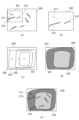
図2(a)は、橋梁の壁面を撮影した画像200を示している。画像200には、ひび割れ211、212、213などの複数のひび割れが写っているとする。また、画像200は、インフラ点検に用いるために高解像で撮影した画像であり、例えば10,000pix×20,000pixのような大きなサイズの画像であるとする。
FIG. 2(a) shows an
ここで、橋梁の表面を撮影した画像200を用いてひび割れを検査する場合には、その画像200について、認識処理でひび割れの認識が可能かどうかを判定する必要がある。従来は、ユーザが、画像200について撮影時の合焦の程度を目視で確認することによって、認識処理でひび割れの認識が可能かどうかを判定している。
Here, when inspecting for cracks using the
図2(b)は、図2(a)に示した画像200内において、例えばひび割れ211、212、213を含む範囲201を拡大した画像202を示した図である。範囲201を拡大した画像202では、ひび割れ211および213はピントずれにより暈けており、一方、ひび割れ211はピントが合っていて殆ど暈けていないとする。なお図2(b)では、暈けているひび割れ211および213を点線で表現している。図2(b)に示した画像202の場合、ひび割れ212はピントが合っていることを確認でき、ひび割れ211および213はピントが合っていないことがわかる。さらに、ひび割れ211は、細いひび割れであり且つ暈けているため、画像202内で視認が難しい。したがって、ひび割れ211は、認識処理において認識できない可能性がある。一方、ひび割れ213は、暈けてはいるが、ある程度の幅がある太いひび割れであるため、画像202内で視認が可能である。したがって、ひび割れ213は、認識処理において認識できる可能性が高い。
FIG. 2(b) is a diagram showing an
このため、ユーザは、画像を拡大して、ピントずれによる暈けと共にひび割れの大きさ(例えば幅)を確認しながら、それぞれのひび割れが認識処理で認識可能であるかどうかを判断する。しかしながら、画像全体について、ひび割れが認識処理で認識可能であるかどうかを判断するためには、画像の一部を拡大して確認する作業を、画像全体に亘って繰り返し行う必要があり、非常に手間がかかる。 Therefore, the user enlarges the image and checks the size (for example, width) of the cracks as well as the blur caused by the out-of-focus image, while determining whether each crack can be recognized by recognition processing. However, in order to determine whether cracks can be recognized by recognition processing for the entire image, it is necessary to repeatedly enlarge and check a part of the image, which is extremely time consuming. It takes time and effort.
そこで、本実施形態の情報処理装置100は、撮影画像について、ひび割れが認識処理で認識可能かどうかを判定する処理を行う。本実施形態の情報処理装置100は、撮影画像に対応するデフォーカス値の分布を表すデフォーカスマップを生成し、そのデフォーカスマップを基に、撮影画像について、認識処理でひび割れを認識可能な範囲を判定する処理を行う。
Therefore, the
図2(c)は、検査対象を撮影した画像200に対応するデフォーカスマップ203を示した図である。デフォーカスマップを作成する方法は、例えば参考文献1(特開2019-134431号公報)に開示されているような、画像の画素毎にデフォーカス値を算出して、デフォーカス値の分布を表すデフォーカスマップを作成する方法を用いることができる。図2(c)の領域221~224は、それぞれが異なるデフォーカス値を示す領域であり、領域221はデフォーカス値が0、領域222はデフォーカス値が+1、領域223はデフォーカス値が+2、領域224はデフォーカス値が+3の領域である。情報処理装置100は、このデフォーカスマップ203の各位置におけるデフォーカス値に基づいて、画像200上で、ひび割れが認識処理で認識可能な範囲を判定して、その判定結果を生成するような判定結果生成処理を実行する。そして、情報処理装置100は、判定結果生成処理による判定結果と撮影で得られた画像200との位置関係を対応付け、画像200に判定結果を重畳させて表示装置の画面上に表示することによって、ユーザに提示する。
FIG. 2C is a diagram showing a
図2(d)は、認識処理でひび割れを認識可能な範囲の判定処理の結果を可視化した、判定結果204の表示例を示した図である。図2(d)において、領域231は、太い(幅が広い)ひび割れについては認識処理で認識可能となる範囲を表している。領域232は、太いひび割れだけでなく微細なひび割れについても認識処理で認識可能となる範囲を表している。一方、領域233は、太いひび割れと微細なひび割れのいずれについても認識処理で認識できない範囲を表している。
FIG. 2D is a diagram illustrating a display example of the
そして、本実施形態の情報処理装置100では、図2(d)に示したような判定結果204を、画像200に重畳して表示する。
図2(e)は、画像200に対して判定結果204を重畳した画像205の例を示した図である。ユーザは、この画像205を観ることで、ひび割れの太さ(幅)ごとに、認識処理で認識可能な範囲を確認することができる。例えば、微細なひび割れ211は、微細なひび割れを認識可能な範囲を表している領域232の外に位置するため、認識処理での認識が難しいと判断できる。一方、太い(幅が広い)ひび割れ213は、太いひび割れを認識可能な範囲を表している領域231内に位置するため、認識処理での認識が行えると判断できる。本実施形態の情報処理装置100によれば、このような判定結果が重畳された画像205を表示することにより、ユーザは、画像200の各位置においてひび割れの認識処理が可能である範囲を容易に確認することができる。
In the
FIG. 2E is a diagram showing an example of an
図1(a)は、第1の実施形態に係る情報処理装置100のハードウェア構成図である。図1(a)に示すように、情報処理装置100は、CPU101、ROM102、RAM103、HDD104、表示部105、操作部106、および通信部107を有している。
FIG. 1A is a hardware configuration diagram of an
CPU101は、中央演算装置(Central Processing Unit)であり、各種処理のための演算や論理判断等を行い、システムバス108に接続された各構成要素を制御する。
ROM(Read-Only Memory)102は、プログラムメモリであって、CPU101が各種処理手順の実行および制御を行うための制御プログラムを格納している。
RAM(Random Access Memory)103は、CPU101の主メモリ、ワークエリア等の一時記憶領域として用いられる。なお、情報処理装置100に接続された外部記憶装置等からRAM103にプログラムをロードすることで、プログラムメモリが実現されてもよい。
The
A ROM (Read-Only Memory) 102 is a program memory, and stores control programs for the
A RAM (Random Access Memory) 103 is used as a temporary storage area such as a main memory or a work area of the
HDD104は、本実施形態に係るデフォーカスマップの作成処理や判定処理等を含む各種の処理をCPU101が実行するためのプログラムや各種設定情報、画像データなどの各種データを記憶しておくためのハードディスクとその駆動装置からなる。なお、本実施形態に係るプログラムは、ROM102に記憶されていてもよい。また、HDD104と同様の役割を果たすものとして外部記憶装置が用いられてもよい。外部記憶装置は、例えば、メディア(記録媒体)と、当該メディアへのアクセスを実現するための外部記憶ドライブとで実現することができる。このようなメディアとしては、例えば、フレキシブルディスク(FD)、CD-ROM、DVD、USBメモリ、MO、フラッシュメモリ等が知られている。また、外部記憶装置は、ネットワークで接続されたサーバ装置等であってもよい。
The
表示部105は、例えばCRTディスプレイや液晶ディスプレイ等の表示装置とその表示装置の表示を制御する表示制御機能とを有し、CPU101によって生成された画像やHDD104から読み出された画像等を表示装置に表示する。なお、表示制御機能はCPU101が担い、表示部105は表示装置のみであってもよい。また、画像等が表示される表示装置は、情報処理装置100と有線あるいは無線で接続された外部表示装置であってもよい。
操作部106は、キーボードやマウス、タッチパネルの操作装置と、ユーザの操作に応じて操作装置から出力される各操作情報を受け付ける操作情報受付機能とを有する。
通信部107は、公知の通信技術により、他の情報処理装置や通信機器、外部記憶装置等との間で、有線又は無線による双方向の通信を行う。
The
The
The
図1(b)は、情報処理装置100の機能構成を示す機能ブロック図の一例である。本実施形態の情報処理装置100は、記憶部121、データ管理部122、デフォーカスマップ作成部123、認識対象設定部124、および判定部125の各機能部を有する。これらの各機能部は、CPU101が、HDD104又はROM102に格納された本実施形態に係るプログラムをRAM103に展開して実行することにより構成される。そして、本実施形態の情報処理装置100では、各機能部によって、後述する各フローチャートの処理が実行される。そして、各機能部による処理の実行結果は、適宜、RAM103に保持される。なお、例えばCPU101を用いたソフトウェア処理の代替としてハードウェアを構成する場合には、ここで説明する各機能部の処理に対応させた演算部や回路を構成すればよい。
FIG. 1B is an example of a functional block diagram showing the functional configuration of the
記憶部121は、少なくとも、撮像装置が検査対象を撮影した画像と、認識対象の認識処理が可能な範囲の判定処理を行う際に用いるモデル情報とを記憶している。検査対象の撮影画像は、本実施形態に係る判定処理に用いられる画像である。記憶部121に記憶されているモデル情報には、学習済みモデルの情報が含まれる。学習済みモデルの詳細は後述する。
The
データ管理部122は、記憶部121が記憶している撮影画像やモデル情報等を管理する。本実施形態において、撮影画像について認識対象の認識処理が可能な範囲を判定する判定処理が行われる場合、データ管理部122は、記憶部121から、検査対象の撮影画像を読み出して、デフォーカスマップ作成部123と判定部125とに転送する。
The
デフォーカスマップ作成部123は、例えば参考文献1に開示された方法を用いて、撮影画像の各画素の位置毎のデフォーカス値を算出し、その位置毎のデフォーカス値の分布を表すデフォーカスマップを作成する。すなわちデフォーカスマップ作成部123は、検査対象を撮影した撮影画像に対応したデフォーカスマップを作成する。
The defocus
認識対象設定部124は、操作部106を介してユーザから入力された指示を基に、認識対象を設定し、その認識対象の設定情報を判定部125に送る。ユーザからの指示に応じた認識対象設定処理の詳細は後述する。
判定部125は、デフォーカスマップを基に、撮影画像について、認識対象の認識処理が可能な範囲を判定する処理を行う。判定部125における判定処理の詳細は後述する。
The recognition
The
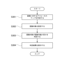
図3は、第1の実施形態の情報処理装置100における情報処理の流れを示すフローチャートである。本実施形態の情報処理装置100は、操作部106を介してユーザから処理開始指示が入力されると、図3のフローチャートの処理を開始する。
FIG. 3 is a flowchart showing the flow of information processing in the
ステップS301において、データ管理部122は、検査対象の撮影画像を記憶部121から読み出してデフォーカスマップ作成部123に転送する。
デフォーカスマップ作成部123は、その撮影画像から各画素の位置毎のデフォーカス値を算出し、それら画素毎のデフォーカス値の分布を表すデフォーカスマップを作成する。前述したように、デフォーカスマップは、検査対象である被写体を撮影した際の当該被写体面におけるデフォーカス値の分布を表したマップであり、例えば参考文献1に例示される公知の方法を用いて作成可能である。なお、デフォーカスマップは、画像の特定の位置におけるデフォーカス値(ピントのズレ量)が算出できるデータであればよく、ラスターデータに限るものではないが、本実施形態ではラスターデータとして扱うものとする。
In step S<b>301 , the
The defocus
デフォーカスマップは撮影画像の各画素に相対した位置座標におけるデフォーカス値をマップ化したものであり、ユーザは、このマップデータを一見しただけでは、デフォーカス値の情報を識別することは困難である。そのため、デフォーカスマップ作成部123は、デフォーカス値を可視化する処理を行う。デフォーカスマップの可視化方法は、例えばデフォーカス値に応じた色やパターンを用い、画素の位置座標毎にデフォーカス値を色やパターンで分けて提示するような方法を用いることができる。デフォーカスマップ作成部123は、デフォーカス値に応じた色やパターンを用いることで、デフォーカス値が変化する部分を境界線として可視化すると共に、各境界線間の領域にデフォーカス値の代表値を可視化した、デフォーカスマップを作成する。
A defocus map is a map of defocus values at positional coordinates relative to each pixel of a photographed image, and it is difficult for users to identify defocus value information just by looking at this map data. be. Therefore, the defocus
図4(a)~図4(c)を用いて、デフォーカスマップを可視化する例を説明する。本実施形態では、インフラ構造物の点検例として、図4(a)に示す橋梁401のようなコンクリート構造物の壁面を点検対象の被写体として撮影したとする。なお、壁面に発生する微細なひび割れなどを認識処理で認識可能にするためには、高解像度で撮影した画像が必要となる。
An example of visualizing a defocus map will be described using FIGS. 4(a) to 4(c). In this embodiment, as an example of inspecting an infrastructure structure, it is assumed that a wall surface of a concrete structure such as a
図4(b)は、点検対象の被写体として、橋梁401の一部の壁面402を撮影した画像411の一例を示した図である。図4(b)の画像411には、橋梁の壁面412と空領域413とが写っている。図4(c)は、画像411の各位置に対応するデフォーカス値を可視化したデフォーカスマップ421の例を示した図である。デフォーカスマップ421の中に記されている数値は、各領域のデフォーカス値の代表値である。領域422のデフォーカス値の代表値は「0」であり、その領域422から外側の領域になるほど、デフォーカス値の代表値の絶対値が大きくなっている。これらのことから、画像411は、画像の中央付近でピントが合い、周辺部になるにしたがってピントずれによる暈けが大きくなっている画像であることが判る。なお、空領域413のように、被写体面(橋梁401の壁面)からの距離が遠い領域では、ピントずれによる暈けが大きくなるため、デフォーカス値の代表値の絶対値が大きくなっている。
FIG. 4(b) is a diagram showing an example of an
図3のフローチャートに説明を戻す。
ステップS301の後、ステップS302に進むと、認識対象設定部124は、撮影画像について認識処理で認識可能か否かの判定が行われる際の認識対象を設定する処理を行う。本実施形態のようにコンクリート構造物の点検が行われる場合、コンクリートの壁面上に発生するひび割れやエフロレッセンス、漏水などが、認識対象として設定される。本実施形態の場合、認識対象設定部124は、例えば、UI(ユーザインタフェース)画面を通じてユーザから指示された認識対象を、認識処理で認識可能か否かの判定が行われる認識対象として設定する。
The explanation returns to the flowchart of FIG.
When the process proceeds to step S302 after step S301, the recognition
図5(a)~図5(c)は、認識対象を選択する際のUI画面の例を示した図である。これらのUI画面に表示される情報は例えばCPU101によって生成される。
図5(a)のUI画面500には、ひび割れやエフロレッセンス、漏水などの複数の認識対象を項目別に並べた認識対象一覧501が用意されている。認識対象一覧501には、項目毎にチェックボックスが設けられている。ユーザが操作部106の操作を通じて所望のチェックボックスにチェックを入れた場合、認識対象設定部124は、そのチェックが入れられた項目に対応した認識対象を、認識処理で認識可能か否かの判定が行われる際の認識対象として設定する。
FIGS. 5(a) to 5(c) are diagrams showing examples of UI screens when selecting a recognition target. The information displayed on these UI screens is generated by the
A
また本実施形態において点検対象として挙げているコンクリート構造物は、環境要因などによって劣化が進行すると、当該構造物の壁面に発生するひび割れやエフロレッセンス等が徐々に進展して大きくなっていくことが多い。したがって、コンクリート構造物の劣化度合いの診断等を目的とする点検の場合、大きなサイズの認識対象が特に重視される。このように特定のサイズの認識対象を重視した認識処理が行われる場合を考慮して、認識処理で認識可能か否かの判定が行われる際の認識対象のサイズ(以下、判定サイズとする)についても設定できるようにすることが望ましい。 Furthermore, as the concrete structures listed as inspection targets in this embodiment progress to deteriorate due to environmental factors, cracks, efflorescence, etc. that occur on the walls of the structures may gradually develop and become larger. many. Therefore, in the case of inspections for the purpose of diagnosing the degree of deterioration of concrete structures, large-sized recognition targets are particularly important. In this way, in consideration of the case where recognition processing is performed with emphasis on a recognition target of a specific size, the size of the recognition target (hereinafter referred to as determination size) when determining whether or not it can be recognized in recognition processing is determined. It is also desirable to be able to set the
図5(b)は、認識対象の判定サイズを設定可能なUI画面502の例を示した図である。図5(b)のUI画面502には、複数の認識対象を項目別に並べた認識対象一覧511が用意されており、この認識対象一覧511には項目毎のチェックボックスに加えて、スライダバー510が設けられている。このUI画面502の場合、ユーザが操作部106を通じて、チェックボックスにチェックを入れると、認識対象設定部124は、そのチェックが入れられた項目に対応した認識対象を、認識処理で認識可能か否かの判定が行われる認識対象として設定する。なお、図5(b)のUI画面502の例では、ひび割れの項目にチェックが入れられているため、認識対象としてはひび割れが設定されている。
FIG. 5B is a diagram showing an example of a
そして、その認識対象(ひび割れ)の項目に対応したスライダバー510が、操作部106を通じてユーザによって操作されると、認識対象設定部124は、そのスライダバー510の操作情報を基に、当該認識対象の判定サイズも設定する。スライダバー510には下限用バー512と上限用バー513が設けられており、ユーザは、操作部106の操作を通じて下限用バー512と上限用バー513の少なくともいずれかを任意の位置にスライドさせることができる。認識対象設定部124は、下限用バー512と上限用バー513との間の間隔に応じて、認識対象の判定サイズを設定する。これにより、下限用バー512と上限用バー513との間の間隔に対応したサイズ(例えばひび割れの幅)が、認識処理で認識可能か否かの判定が行われる認識対象の判定サイズとして設定される。
Then, when the
なお、下限用バー512と上限用バー513は、スライダバー510のスライド可能範囲内においてそれぞれ別個にスライド操作可能となされているが、下限用バー512と上限用バー513のスライド動作が連動するようになされていてもよい。つまり、例えば下限用バー512と上限用バー513との間隔が保持され、一方のスライド操作に連動して他方もスライドするようになされていてもよい。また前述の例では、認識対象としてひび割れを挙げているが、認識対象設定部124は、ひび割れ以外の認識対象が選択された場合にも、当該認識対象のサイズを設定可能である。例えば、ひび割れ以外の認識対象の判定サイズを設定する例としては、例えば当該認識対象の面積(面積サイズ)などの属性を設定する場合などが挙げられる。
Note that the
図5(b)では、スライダバー510の操作によって認識対象の判定サイズを設定可能にする例を挙げたが、認識対象の判定サイズごとに区分けした認識対象一覧をUI画面に表示させて、その中からユーザが任意のサイズの認識対象を選択する例でもよい。図5(c)は、認識対象の判定サイズごとに区分けした認識対象一覧521を表示したUI画面503の例を示した図である。図5(c)の認識対象一覧521が、ひび割れのサイズ毎に区分けされた一覧の例である。この認識対象一覧521にも前述同様に項目毎のチェックボックスが設けられている。認識対象設定部124は、図5(c)のUI画面503の認識対象一覧521のチェックボックスにチェックを入れるユーザの選択操作に基づいて、認識対象およびその認識対象の判定サイズを設定する。
In FIG. 5(b), an example was given in which the judgment size of the recognition target can be set by operating the
図3のフローチャートに説明を戻す。
ステップS302の後、ステップS303に進むと、判定部125は、検査対象の撮影画像について、認識対象設定部124で設定された認識対象の認識処理が可能な範囲を判定する処理を行う。本実施形態の場合、判定部125は、デフォーカスマップ作成部123からデフォーカスマップを取得し、デフォーカスマップの各位置に対応する判定結果を出力する。本実施形態の判定部125における判定処理について、図6(a)~図6(f)を用いて説明する。
The explanation returns to the flowchart of FIG.
When the process proceeds to step S303 after step S302, the
判定部125は、デフォーカスマップの各位置におけるデフォーカス値を基に、撮影画像について、認識対象の認識処理が可能な範囲を判定する。デフォーカスマップの各位置のデフォーカス値に基づく判定処理は、式(1)で表すことができる。
The
Dt1≦Di≦Dt2 式(1) Dt1≦Di≦Dt2 Formula (1)
ここで、式(1)で用いるパラメータDiは、デフォーカスマップの一つの着目画素の位置iにおけるデフォーカス値である。パラメータDt1,Dt2はそれぞれ、認識対象の認識処理が可能か否かを判定する際の境界を表すデフォーカス基準値であり、パラメータDt1はデフォーカス基準値の下限値、パラメータDt2は上限値である。つまり本実施形態において、デフォーカス基準値は下限値から上限値までの間の幅を有したものとなされている。これらパラメータDt1,Dt2の値は、例えば実験的に求めた値であってもよいし、ユーザが指定した値であってもよい。 Here, the parameter Di used in equation (1) is the defocus value at position i of one pixel of interest in the defocus map. Parameters Dt1 and Dt2 are defocus reference values representing the boundaries when determining whether recognition processing of a recognition target is possible, respectively, parameter Dt1 is the lower limit of the defocus reference value, and parameter Dt2 is the upper limit. . That is, in this embodiment, the defocus reference value has a range from the lower limit value to the upper limit value. The values of these parameters Dt1 and Dt2 may be, for example, experimentally determined values or values specified by the user.
図6(a)は、デフォーカス基準値の一例として、認識対象がひび割れである場合の、ひび割れの大きさ(ひび割れの幅)毎のデフォーカス基準値601を示した図である。図6(a)に示すように、本実施形態においてデフォーカス基準値は、ひび割れの大きさ(幅)毎に異なる下限値および上限値が決められている。
FIG. 6A is a diagram showing a
まず図6(a)に示したデフォーカス基準値601と式(1)とを用いた判定処理の一例として、認識対象である細いひび割れが、認識処理で認識可能か否かの判定処理を挙げて説明する。
First, as an example of a determination process using the
この場合、判定部125は、デフォーカス基準値601から、細いひび割れに対するデフォーカス基準値の下限値と上限値とを取得する。図6(a)に示したデフォーカス基準値601の場合、細いひび割れに対するデフォーカス基準値の下限値は-1であり、上限値は+1である。このため、判定部125は、パラメータDt1として-1を取得し、パラメータDt2として+1を取得する。
In this case, the
次に、判定部125は、デフォーカスマップの着目画素の位置iにおけるデフォーカス値Diを取得する。そして、判定部125は、その位置iについて取得したデフォーカス値Diを式(1)に代入し、式(1)を満たす場合に、当該位置iでは細いひび割れを認識可能であると判定し、そうでない場合、ひび割れを認識できないと判定する。判定部125は、この式(1)による判定処理を、着目画素の位置iを順次変更しながら、デフォーカスマップの全ての位置iについて行う。これにより、判定部125は、デフォーカスマップの全ての位置iにおける細いひび割れの判定結果を取得することができる。
Next, the
前述したようなデフォーカス基準値と式(1)を用いた判定処理は、複数の認識対象が設定された場合にも適用可能である。例えば、認識対象設定部124で二つの認識対象(例えば中程度のひび割れと極細ひび割れなど)が設定された場合、判定部125は、まず一つ目の認識対象として中程度のひび割れを選択する。さらに、判定部125は、その中程度のひび割れに対するデフォーカス基準値の下限値と上限値を取得する。図6(a)に例示したデフォーカス基準値601の場合、中程度ひび割れに対するデフォーカス基準値の下限値は-2であり、上限値は+2であるため、判定部125は、パラメータDt1として-2を取得し、パラメータDt2として+2を取得する。そして、判定部125は、デフォーカスマップの各位置のデフォーカス値が式(1)を満たすか否か判定することで、デフォーカスマップ全体の判定結果を求める。判定部125は、中程度のひび割れに対する判定処理が終了すると、次に、二つ目の認識対象として極細ひび割れを選択する。図6(a)のデフォーカス基準値601の場合、極細ひび割れに対するデフォーカス基準値の下限値と下限値は共に0であるため、判定部125は、パラメータDt1,Dt2としてそれぞれ0を取得する。そして、判定部125は、前述同様に、デフォーカスマップの各位置のデフォーカス値が式(1)を満たすか否か判定してデフォーカスマップ全体の判定結果を求める。
The determination process using the defocus reference value and equation (1) as described above can be applied even when a plurality of recognition targets are set. For example, when the recognition
判定部125における判定処理では、例えば、機械学習により学習した学習済みモデルを利用することも可能である。この場合、使用する学習済みモデルは、デフォーカスマップと、デフォーカスマップの各位置における認識対象の判定可否を示す教師データとのペアを学習データとして、機械学習により学習させたモデルである。学習済みモデルは、デフォーカスマップを入力データとして、認識対象が認識可能かもしくは認識不可能かのいずれかを出力するモデルであり、例えばニューラルネットワークモデルで構成可能である。
In the determination process in the
図6(b)には、ひび割れの大きさ(幅)毎の学習済みモデル602の例を示した図である。学習済みモデル602を用いた判定処理を行う場合、判定部125は、認識対象設定部124で設定された認識対象に基づいて、当該学習済みモデル602の中からいずれかのモデルを選択する。例えば、認識対象設定部124において認識対象として太いひび割れが設定された場合、学習済みモデル602の中から、太いひび割れを認識対象とするモデルM2を選択する。判定部125は、このように選択したモデルM2を分類器とし、デフォーカスマップを入力として、太いひび割れが認識可能か否かを分類(つまり判定)する。そして、判定部125は、その判定処理により、デフォーカスマップの各位置に対する太いひび割れに対する判定結果を出力する。
FIG. 6(b) is a diagram showing an example of a learned
また学習済みモデルを利用する例は、認識対象設定部124で複数の認識対象が設定された場合も適用可能である。例えば、認識対象設定部124で二つの認識対象(極太ひび割れ、細いひび割れ)が設定された場合、判定部125は、まず一つ目の認識対象として極太ひび割れを選択する。次に、判定部125は、学習済みモデル602の中から、極太ひび割れを認識対象とするモデルM1を分類器とする。そして、判定部125は、デフォーカスマップの入力に対して判定処理を行う。判定部125は、判定処理が終了したならば、二つ目の認識対象として細いひび割れを選択し、同様にモデル選択と判定処理を繰り返す。認識対象がさらに増えた場合も、同様の処理を行えばよい。
Further, the example of using a trained model is also applicable when a plurality of recognition targets are set by the recognition
本実施形態において、分類器に用いるモデルを選択する方法として、ユーザが、モデル一覧の中から直接選択してもよい。ユーザがモデルを選択する場合、判定部125は、ユーザの指定したモデルをデータ管理部122から取得した後、判定処理を行う。なお、前述の学習済みモデルは、必要に応じて、予め決めた一定の処理後に更新しても良い。
In this embodiment, as a method for selecting a model to be used in a classifier, the user may directly select one from a list of models. When the user selects a model, the
前述の実施形態では、ひび割れ幅のような認識対象のサイズ毎の学習済みモデルやデフォーカス基準値を用いて判定処理を行う方法を説明したが、認識対象のサイズによらず、共通の学習済みモデルやデフォーカス基準値を用いてもよい。例えば、図6(c)のような認識対象ごとの学習済みモデルや、図6(d)のようなデフォーカス基準値を予め用意する。そして、判定部125は、認識対象設定部124で設定された認識対象に合わせて学習済みモデルやデフォーカス基準値を選択すればよい。またさらに、認識対象の種類によらず、共通の学習済みモデルやデフォーカス基準値が用いられてもよい。
In the embodiment described above, a method was described in which the judgment process is performed using a trained model and a defocus reference value for each size of the recognition target such as crack width. However, regardless of the size of the recognition target, a common trained model A model or defocus reference value may be used. For example, a learned model for each recognition target as shown in FIG. 6(c) or a defocus reference value as shown in FIG. 6(d) is prepared in advance. Then, the determining
前述の本実施形態では、デフォーカスマップ全体の位置について同じ判定処理を行う例を挙げたが、例えば、デフォーカスマップを画素単位より大きい領域毎に区分けし、それら区分けした区分領域毎に異なる方法で判定処理を行ってもよい。デフォーカスマップを領域毎に区分けする場合には、例えばデフォーカス値に基づいてデフォーカスマップを区分領域毎に分け、それら区分領域毎に異なる学習済みモデルを分類器として用いて判定処理を行う方法が考えられる。 In the above embodiment, an example was given in which the same determination process is performed for the position of the entire defocus map, but for example, the defocus map may be divided into areas larger than the pixel unit, and a different method may be used for each divided area. The determination process may be performed using When dividing a defocus map into regions, for example, the defocus map is divided into regions based on the defocus value, and a different trained model is used as a classifier for each region to perform judgment processing. is possible.
図6(e)は例えばデフォーカス値が+8と0のような、値が大きく異なる二つのデフォーカス値をもつデフォーカスマップ611を示した図である。図6(f)はデフォーカス値毎の学習済みモデル621を示した図である。図6(e)に示したデフォーカスマップ611は、デフォーカス値によって区分領域612と区分領域613とに区分けされている。図6(f)に示す学習済みモデル621は、デフォーカスマップの特定のデフォーカス値と判定結果の教師データとのペアを主な学習データとして学習させたモデルである。そして、判定部125は、デフォーカスマップ611を入力として、学習済みモデル621を分類器として、ひび割れの判定処理を行うとする。この場合、判定部125は、デフォーカスマップ611を区分領域612と613に区分けし、それら区分領域612と613のデフォーカス値に基づいて、学習済みモデル621からそれぞれモデルを選択して判定処理を行う。すなわちこの例の場合、判定部125は、区分領域612はデフォーカス値が0であるためモデルM21を選択し、区分領域613はデフォーカス値が+8であるためモデルM22を選択する。そして、判定部125は、デフォーカス値に応じた区分領域毎に適した学習済みモデルを使用して判定処理を行う。
FIG. 6E is a diagram showing a
その他にも、デフォーカスマップの区分領域毎に異なる判定処理を行う場合の他の例として、区分領域毎に、学習済みモデルを分類器として判定する方法と、デフォーカス基準値および式(1)を用いた判定方法とが併用されてもよい。 In addition, as another example of performing different determination processing for each segmented area of a defocus map, there is a method of determining a trained model as a classifier for each segmented area, a defocus reference value, and formula (1). A determination method using the method may also be used in combination.
図3のフローチャートに説明を戻す。
ステップS303の後、ステップS304に進むと、情報処理装置100は、判定部125による判定結果を表示するための表示データを作成し、それを表示する。なお、表示データの作成はCPU101が行う。そして、本実施形態の情報処理装置100は、判定結果の表示が完了したら、図3のフローチャートの処理を終了する。
The explanation returns to the flowchart of FIG.
When the process proceeds to step S304 after step S303, the
本実施形態において判定結果を表示する場合、判定結果は、図2(d)に例示したデフォーカスマップの可視化の例と同様に、例えば色やパターン(ただしデフォーカスマップで用いたものとは異なる色やパターン)で分ける方法等により表示することができる。すなわち判定結果は、判定結果が変化する部分が、色やパターンの違いにより境界線として可視化される。また本実施形態において、複数の認識対象についてそれぞれ判定処理が行われた場合には、それら認識対象毎にそれぞれ色やパターンを異ならせるようにして判定結果を可視化する。 When displaying the determination results in this embodiment, the determination results may be displayed in different colors or patterns (however, different from those used in the defocus map), similar to the example of visualization of the defocus map illustrated in FIG. 2(d). It can be displayed by dividing by color or pattern. That is, in the determination result, the portion where the determination result changes is visualized as a boundary line by using a difference in color or pattern. Further, in this embodiment, when determination processing is performed for each of a plurality of recognition targets, the determination results are visualized by using different colors and patterns for each of the recognition targets.
図7(a)~図7(e)は、判定結果の表示方法の説明に用いる図である。
図7(a)は、複数の認識対象についてそれぞれ判定処理が行われた場合の判定結果を可視化した判定結果701を示した図であり、例えばひび割れとエフロレッセンスについての判定結果を示している。判定結果701において、実線で囲われた領域702はひび割れについての判定結果を表し、点線で囲われた領域703はエフロレッセンスについての判定結果を表している。
FIGS. 7(a) to 7(e) are diagrams used to explain a method of displaying determination results.
FIG. 7A is a diagram illustrating a
図7(b)は、図7(a)に示した判定結果701を撮影画像に重畳して作成した判定結果画像711を画面712上に表示した例を示した図である。図7(b)のような判定結果701を撮影画像に重畳した判定結果画像711が表示されることで、ユーザは、撮影画像の各位置で、認識対象が認識可能か否かを容易に確認可能となる。また、本実施形態の情報処理装置100は、図7(b)に示すように、画面712上に、判定処理がなされた各認識対象が項目として表された認識対象一覧713も表示することができる。認識対象一覧713の各項目にはチェックボックスが配されており、情報処理装置100は、チェックが入れられた認識対象の判定結果を表す領域を撮影画像に重畳した判定結果画像711を表示する。図7(b)の場合、認識対象一覧713のひび割れとエフロレッセンスの両方の項目についてチェックが入れられているため、判定結果画像711にはひび割れの判定結果を表す領域702と、エフロレッセンスの判定結果を表す領域703の両方が表示されている。なお、例えばエフロレッセンスの判定結果を非表示にしたい場合、ユーザは、認識対象一覧713の項目のうち、エフロレッセンスの項目のチェックボックス714のチェックを外す操作を行えばよい。このように、本実施形態の情報処理装置100では、判定結果の表示のオン、オフを、認識対象一覧713のチェックボックスに対するチェックの有無により切り替え可能となされている。すなわち情報処理装置100は、ユーザ操作に基づいて、判定結果画像711を再作成して、画面712に表示する処理を再実行可能となされており、複数の認識対象に係る判定結果のうち、特定の認識対象のみを表示するようなことが可能となされている。
FIG. 7B is a diagram showing an example in which a
また、他の表示方法として、本実施形態の情報処理装置100は、画像中の特定の位置において、認識可能な認識対象リストを表示することも可能である。
例えば図7(b)の画面712において、ユーザが、いわゆるマウスオーバー等の操作を行い、判定結果画像711上の所望の位置715付近にマウスカーソル716の先端を合わせたとする。この場合、情報処理装置100は、そのユーザ操作に基づいて、位置715を注目位置として設定し、その注目位置における判定結果を読み込み、図7(c)に示すような認識可能な認識対象リストを生成して表示部105の画面上にポップアップ等で表示する。
Furthermore, as another display method, the
For example, on the
図7(c)中の注目位置座標(x1,y1)は、例えば判定結果画像711中の左上頂点を原点(0,0)としたときの、画面水平方向(x方向)と垂直方向(y方向)の位置座標である。図7(c)のような認識対象リストを表示することにより、ユーザは、判定結果画像711内の特定の位置において認識可能な認識対象の一覧を確認しやすくなる。なお、異なる位置について認識可能な認識対象の一覧を確認したい場合、ユーザは、マウスカーソル716の位置を変更すればよい。すなわち情報処理装置100は、このようなユーザによるマウスカーソル716の位置変更操作に基づいて、注目位置を再設定する。そして、情報処理装置100は、その変更後の注目位置における判定結果の再読み込みを行い、認識可能な認識対象リストを更新して再表示する。
The attention position coordinates (x1, y1) in FIG. 7(c) are, for example, the screen horizontal direction (x direction) and the vertical direction (y direction). By displaying the recognition target list as shown in FIG. 7C, the user can easily check the list of recognition targets that can be recognized at a specific position in the
本実施形態において、判定結果を表示する際の他の例として、情報処理装置100は、判定結果をサマリ表示することも可能である。
図7(d)は、判定結果をサマリ表示する場合の例を示した図である。図7(d)は、ひび割れの大きさ(幅)毎の判定結果721のサマリ表示例を示している。判定結果721において、認識可能比率とは、撮影画像全体の面積に対し、ひび割れを認識可能と判定した領域の面積比率である。また、判定サマリとは、認識可能比率が高い場合(例えば80%以上の場合)にOKとし、そうでない場合にNGとした判定結果である。このようなサマリ表示が行われることにより、ユーザは、画像上で各認識対象が判定可能か否かを確認し易くなる。
In the present embodiment, as another example of displaying the determination results, the
FIG. 7(d) is a diagram showing an example of a case where a summary of the determination results is displayed. FIG. 7D shows an example of a summary display of the determination results 721 for each crack size (width). In the
さらに他の表示方法の例として、情報処理装置100は、図7(e)のように、認識可能と判定した認識対象ごとのサイズをグラフ形式で表示することも可能である。図7(e)において、例えば認識対象のひび割れを表すグラフの斜線部731は、ひび割れの判定結果に基づいて、どのようなサイズまでのひび割れが認識可能かを可視化した結果である。斜線部731の下端が認識可能なひび割れのサイズの下限に対応し、斜線部731の上端が認識可能なひび割れのサイズの上限に対応している。この図7(e)に例示したような可視化が行われることにより、ユーザは、認識対象ごとに認識可能なサイズを確認し易くなる。
As another example of a display method, the
<第1の実施形態の変形例>
第1の実施形態では、判定部125の判定処理において、学習済みモデルを利用する例を挙げて説明したが、学習の不十分なモデルを利用して認識判定を行うような変形例も本実施形態に含めることができる。この例の場合、まず、少ない量の学習データで学習させたモデルを初期モデルとする。そして、判定部125は、その初期モデルを分類器とし、デフォーカスマップを入力して、認識対象設定部124で設定された認識対象に対する判定処理を行い、その判定結果を出力する。さらにこの例の場合、その判定結果を例えばユーザが修正した場合、その修正結果とデフォーカスマップのペアを学習データとして利用し、初期モデルを機械学習により再学習させる。このような判定処理とモデル学習とを繰り返すことにより、認識判定性能の高い学習済みモデルの作成が可能となる。
<Modification of the first embodiment>
In the first embodiment, an example in which a trained model is used in the determination process of the
<他分野への適用例>
以上の実施形態では、インフラ点検における検査対象を撮影した画像から、ひび割れ等の認識対象を認識可能な範囲を判定する例を挙げて説明したが、本実施形態に係る情報処理の適用先は特定の分野に限定されない。例えば、製造工場等において、製品を撮影した画像からキズなどの欠陥を確認する作業(外観検査)などにも、本実施形態の情報処理は適用可能である。外観検査では、製造工場等で製造する製品の外観が要求品質を満たすかどうかを、製品の撮影画像を用いた画像認識処理により実施する。この検査において、本実施形態の情報処理を適用することにより、製品画像からキズ等の欠陥を認識可能な範囲の判断に係るユーザの作業を効率化することができる。
<Example of application to other fields>
In the above embodiment, an example was given in which the range in which a recognition target such as a crack can be recognized is determined from an image taken of an inspection target in infrastructure inspection. However, the information processing according to this embodiment is applied to a specific target. is not limited to the field of For example, the information processing of this embodiment can be applied to work (external appearance inspection) in which defects such as scratches are confirmed from images taken of products in manufacturing plants and the like. In the appearance inspection, whether the appearance of a product manufactured at a manufacturing factory or the like satisfies the required quality is performed by image recognition processing using a photographed image of the product. In this inspection, by applying the information processing of this embodiment, the user's work related to determining the range in which defects such as scratches can be recognized from the product image can be made more efficient.
以上説明したように、第1の実施形態によれば、検査対象の被写体を撮影した画像から、ひび割れ等の認識対象を認識可能な範囲を判断する際のユーザ作業を支援することにより、ユーザ作業を軽減して、作業の効率を高めることができる。 As described above, according to the first embodiment, by supporting the user's work when determining the range in which recognition targets such as cracks can be recognized from the image taken of the subject to be inspected, the user's work can be reduced and work efficiency can be increased.
<第2の実施形態>
第1の実施形態では、撮影画像に対応したデフォーカスマップのみを用いて、当該撮影画像について認識対象を認識可能な範囲を判定する例を挙げた。ここで、インフラ点検において、橋梁やトンネルなどのコンクリート壁面は、経年劣化により汚れ等が蓄積することで、撮影画像におけるテクスチャが複雑化することが多い。テクスチャが複雑化すると、壁面上のひび割れ等が視認し難くなるため、ピントの合った画像であっても、ひび割れ等を認識することが難しくなる可能性がある。
<Second embodiment>
In the first embodiment, an example was given in which only the defocus map corresponding to the captured image is used to determine the range in which the recognition target can be recognized for the captured image. In infrastructure inspections, concrete walls such as bridges and tunnels often accumulate dirt and the like due to deterioration over time, resulting in complex textures in photographed images. When the texture becomes complicated, it becomes difficult to visually recognize cracks and the like on the wall surface, so even if the image is in focus, it may be difficult to recognize the cracks and the like.
そこで、第2の実施形態の情報処理装置では、複雑なテクスチャが含まれる撮影画像について判定処理を行う際、当該撮影画像に対して所定の画像処理を行って得たデータを、画像のテクスチャに関連する追加データとして生成する。そして、第2の実施形態の情報処理装置は、前述同様のデフォーカスマップと画像のテクスチャに関連した追加データとに基づいて判定処理を行う。すなわち第2の実施形態の情報処理装置は、画像のテクスチャに関連した追加データを加味した判定処理を行うことにより、複雑なテクスチャが含まれた撮影画像であっても、認識対象を認識可能な範囲の誤判定を少なくし、高い精度での判定を可能とする。本実施形態の情報処理装置は、撮影画像に対する所定の画像処理として、画像の特徴量を抽出して、画像特徴量からなるマップデータを、追加データとして生成する処理を行う。より具体例には、第2の実施形態では、撮影画像に対し、例えばFFT処理(高速フーリエ変換処理)を行って、撮影画像の高周波成分のみを抽出し、その高周波成分のみからなるマップデータを、撮影画像のテクスチャに関連する追加データとして生成する。ただし高周波の範囲は任意に定められてよい。 Therefore, in the information processing apparatus of the second embodiment, when performing determination processing on a photographed image that includes a complex texture, data obtained by performing predetermined image processing on the photographed image is applied to the texture of the image. Generate as additional relevant data. Then, the information processing apparatus of the second embodiment performs the determination process based on the same defocus map as described above and additional data related to the texture of the image. In other words, the information processing device of the second embodiment can recognize the recognition target even if the captured image includes a complex texture by performing a determination process that takes into account additional data related to the texture of the image. To reduce misjudgment of range and enable highly accurate judgment. As predetermined image processing for a photographed image, the information processing apparatus of this embodiment performs a process of extracting feature amounts of the image and generating map data consisting of the image feature amounts as additional data. More specifically, in the second embodiment, for example, FFT processing (fast Fourier transform processing) is performed on a photographed image to extract only high frequency components of the photographed image, and map data consisting only of the high frequency components is created. , generated as additional data related to the texture of the captured image. However, the range of high frequencies may be determined arbitrarily.
以下、第1の実施形態との差分を中心に、第2の実施形態における情報処理装置について説明する。
第2の実施形態に係る情報処理装置のハードウェア構成は、図2(a)に示したハードウェア構成に準ずるため、それらの説明は省略する。
図8は、第2の実施形態の構成に係る情報処理装置800の機能ブロック図の一例を示した図である。図8に示した構成は、第1の実施形態の図2(b)に示した構成に対して、追加データ設定部126が設けられている点が異なる。追加データ設定部126は、CPU101により実行される一機能部であって、第2の実施形態での判定処理に用いる追加データを設定する追加設定処理を行う。なお図8の機能ブロックにおいて、追加データ設定部126以外の他の機能部は、図2(a)に示した各機能部に準ずるため、それらの説明は省略する。
The information processing apparatus according to the second embodiment will be described below, focusing on the differences from the first embodiment.
The hardware configuration of the information processing apparatus according to the second embodiment is similar to the hardware configuration shown in FIG. 2(a), so a description thereof will be omitted.
FIG. 8 is a diagram showing an example of a functional block diagram of an
図9は、第2の実施形態に係る情報処理装置800における情報処理の流れを示すフローチャートである。図9のフローチャートにおいて、第1の実施形態で示した図3のフローチャートと同じ参照番号を付した処理ステップでは、第1の実施形態と同様の処理が実行されるため、それらの説明は省略する。
FIG. 9 is a flowchart showing the flow of information processing in the
第2の実施形態の場合、ステップS302で認識対象が設定された後、ステップS901へ進む。ステップS901に進むと、追加データ設定部126は、前述したように撮影画像をFFT処理して得た高周波成分からなるマップデータを、撮影画像のテクスチャに関連する追加データとして設定する。
In the case of the second embodiment, after the recognition target is set in step S302, the process advances to step S901. Proceeding to step S901, the additional
続くステップS902において、判定部125は、ステップS301で算出されたデフォーカスマップと、ステップS901で設定した追加データ(撮影画像の高周波成分からなるマップデータ)とを用いて、認識対象を認識可能な範囲の判定処理を実行する。その後、ステップS304において、情報処理装置100は、判定結果を表示部105に表示させる。
In subsequent step S902, the
ステップS901の追加データ設定処理について、図10(a)と図10(b)を用いて説明する。
図10(a)は、劣化が進行している構造物壁面を撮影した画像1001の例を示した図である。画像1001のうち、領域1002は、壁面汚れによって、ひび割れ1011が視認し難い状態になっているとする。一方、領域1003は、壁面汚れが少ないため、ひび割れ1012は視認し易い状態であるとする。
The additional data setting process in step S901 will be explained using FIG. 10(a) and FIG. 10(b).
FIG. 10A is a diagram showing an example of an
図10(b)は、図10(a)の画像1001に対応するデフォーカスマップ1004を示した図である。デフォーカスマップ1004のデフォーカス値の大部分は0であるとする。したがって、画像1001は、全体的にピントの合った画像である。ただし、デフォーカスマップ1004は、被写体面のデフォーカス値の情報は含むが、被写体面のテクスチャの情報を含まない。
FIG. 10(b) is a diagram showing a
このため、追加データ設定部126は、画像1001をFFT処理して高周波数成分を抽出し、その高周波数成分のみを含むマップデータを作成し、当該マップデータを、画像1001のテクスチャに関連する追加データとして設定する。
Therefore, the additional
なお、追加データとしては、高周波数成分のみを含むマップデータの他にも、例えば撮影画像のエッジマップが使用されてもよい。エッジマップを生成する場合、追加データ設定部126は、撮影画像からエッジ輪郭成分を抽出し、そのエッジ輪郭成分を含むマップデータを追加データとして設定する。画像からエッジ輪郭成分を抽出する処理としては、いわゆるCanny法を用いた処理を挙げることができる。さらに他の例として、撮影画像データの例えば赤(R)、緑(G)、青(B)の3チャネルからなるRGB画像データそのものを、追加データとして設定することも可能である。
Note that, in addition to map data containing only high frequency components, for example, an edge map of a captured image may be used as the additional data. When generating an edge map, the additional
次にステップS902にて判定部125で行われる、デフォーカスマップと追加データとを用いた判定処理について説明する。
判定部125は、認識対象に対する判定処理において、第1の実施形態と同様に、機械学習により学習させた学習済みモデルを、判定処理で用いる分類器として利用することができる。第2の実施形態の学習済みモデルは、デフォーカスマップと追加データとを入力とし、デフォーカスマップの各位置における判定結果を示す教師データのペアを学習データとして学習させたモデルである。この学習済みモデルは、例えば、ニューラルネットワークモデルで構成可能である。各モデルの選択方法や結果出力などは、第1の実施形態と同様であるため、その説明は省略する。
Next, the determination process using the defocus map and additional data performed by the
In the determination process for the recognition target, the
第2の実施形態においても前述した第1の実施形態で説明したのと同様に、学習の不十分なモデルを利用して判定処理が行われてもよい。この場合、少ない量の学習データで学習させた初期モデルを用意し、デフォーカスマップと追加データとを入力として、認識対象に対する判定処理を行う。そして、その判定結果をユーザが修正した場合、その修正結果とデフォーカスマップとのペアを学習データとして利用して、初期モデルを機械学習により再学習させる。このような判定処理とモデル学習を繰り返すことにより、判定性能の高いモデルを作成することができる。 In the second embodiment as well, as described in the first embodiment, the determination process may be performed using an insufficiently trained model. In this case, an initial model trained using a small amount of training data is prepared, and the defocus map and additional data are used as input to perform judgment processing on the recognition target. When the user modifies the determination result, the initial model is retrained by machine learning using a pair of the modified result and the defocus map as learning data. By repeating such judgment processing and model learning, a model with high judgment performance can be created.
図10(c)は、図10(a)に示した画像1001について、認識対象のひび割れについて、第2の実施形態の判定部125による判定処理で判定された結果を可視化した、判定結果1021の一例を示した図である。
図10(c)に示した判定結果1021のうち、領域1022はひび割れを認識可能と判定した領域であり、一方、領域1023はひび割れを認識できないと判定した領域である。領域1022と領域1023の各位置におけるデフォーカス値は、図10(b)のデフォーカスマップ1004で示したように大半が「0」であるため、領域1022と領域1023のどちらの領域もおよそピントが合っている。第2の実施形態の場合、デフォーカスマップ1004に加えて、テクスチャに関連する追加データをも使用して判定処理を行うことにより、撮影画像のテクスチャを考慮した判定処理がなされることになる。これにより、第2の実施形態に係る判定処理では、領域1023はひび割れを認識できない領域として適切に判定することができる。すなわち、第2の実施形態によれば、撮影した画像中の被写体面が汚れているような場合であっても、画像のテクスチャを考慮した判定処理を行うことができる。
FIG. 10(c) shows a
Among the determination results 1021 shown in FIG. 10(c), a
<第3の実施形態>
第1~2の実施形態で説明した判定処理によって、撮影画像中の各位置で認識対象を認識できないと判定された画像は、通常は、認識処理に適さない画像となる。この場合、代わりの画像を取得するために再撮影が必要となる。しかしながら、インフラ構造物の壁面を高解像度に撮影する作業は手間がかかる。
<Third embodiment>
An image in which it is determined that the recognition target cannot be recognized at each position in the captured image by the determination processing described in the first and second embodiments is usually an image that is not suitable for recognition processing. In this case, reshooting is required to obtain a replacement image. However, photographing the walls of infrastructure structures at high resolution is time-consuming.
そこで、第3の実施形態では、撮影画像が認識処理に適さない画像である場合に、判定処理に使用する画像データに対して所定の画像加工処理を施し、その画像加工処理後の画像データを使用して再度、判定処理を行う。そして、再判定処理の結果、撮影画像のなかで認識対象を認識可能な範囲が増える(拡大する)と、認識処理に適した画像として活用できる可能性が高くなる。第3の実施形態における所定の画像加工処理としては、例えば、撮影画像のコントラストを変換するような処理を挙げることができる。以下、第3の実施形態では、第2の実施形態との差分を中心に説明する。 Therefore, in the third embodiment, when a captured image is an image that is not suitable for recognition processing, a predetermined image processing process is performed on the image data used for the determination process, and the image data after the image processing process is Then, perform the determination process again. As a result of the re-determination process, if the range in which the recognition target can be recognized in the photographed image increases (expands), the possibility that the image can be used as an image suitable for the recognition process increases. As the predetermined image processing in the third embodiment, for example, processing such as converting the contrast of a photographed image can be mentioned. Hereinafter, the third embodiment will be explained focusing on the differences from the second embodiment.
第3の実施形態に係る情報処理装置のハードウェア構成は、第2の実施形態と同様に、第1の実施形態の図2(a)に示した構成に準じるため、その説明を省略する。図11(a)は、第3の実施形態の構成に係る情報処理装置1100の機能ブロック図の一例を示した図である。第3の実施形態の情報処理装置1100は、第2の実施形態の図8に示した構成に対して、判断部127、範囲設定部128、加工部129、受付部130が設けられている点が異なる。なお、図11(b)の説明は後述する。
Similar to the second embodiment, the hardware configuration of the information processing apparatus according to the third embodiment is based on the configuration shown in FIG. 2(a) of the first embodiment, so a description thereof will be omitted. FIG. 11A is a diagram showing an example of a functional block diagram of an
受付部130は、CPU101の機能部であって、ユーザからの画像データ入力を受け付ける処理を行う。なお、受付部130は、図1(a)に示した第1の実施形態の情報処理装置100や図8に示した第2の実施形態の情報処理装置800にも、それぞれ備えられていてもよい。
The
判断部127は、CPU101の機能部であって、判定部125による1度目の判定処理の結果に基づいて、2度目の判定処理を行うか否かを判断する処理を行う。判断部127における判断処理の詳細は後述する。
範囲設定部128は、CPU101の機能部であって、判断部127で2度目の判定処理を行うと判断された際に、撮影画像のなかで当該2度目の判定処理を行う画像範囲を設定する処理を行う。範囲設定部128における範囲設定処理の詳細は後述する。
加工部129は、CPU101の機能部であって、判断部127で2度目の判定処理を行うと判断された際に、範囲設定部128で設定された画像範囲の画像データに対して所定の画像加工処理を行う。加工部129における画像加工処理の詳細は後述する。
The determining
The
The
図12は、第3の実施形態に係る情報処理装置1100が実行する情報処理の流れを示すフローチャートである。図12のフローチャートにおいて、第1の実施形態で示した図3のフローチャートおよび第2の実施形態で示した図9のフローチャートとそれぞれ同じ処理ステップには前述と同じ参照番号を付し、それらの説明は省略する。
FIG. 12 is a flowchart showing the flow of information processing executed by the
ステップS1201において、受付部130は例えばユーザがデジタルスチルカメラ等に代表される汎用的な撮像装置を用いて検査対象の構造物壁面等を撮影した画像のデータ(RGBデータ)を受け付ける。受付部130にて取得された画像データは、データ管理部122を介して記憶部121に記憶される。そして、第3の実施形態の情報処理装置1100において1度目の判定処理が行われる場合、データ管理部122は、記憶部121からその画像データを読み出して、デフォーカスマップ作成部123と判定部125へ転送する。
In step S1201, the
次のステップS301において、デフォーカスマップ作成部123は、前述の実施形態で説明したのと同様にして、デフォーカスマップを作成する。
続いてステップS302において、認識対象設定部124は、前述の実施形態で説明したのと同様にして認識対象を設定する。
次のステップS901に進むと、追加データ設定部126は、撮影画像に所定の画像処理を施して追加データとして設定する。ただし第3の実施形態の場合、ステップS901では、構造物壁面を撮影した画像データのRGBの3チャネルからなるRGB画像が、追加データとして設定される。
そして次のステップS902において、判定部125は、デフォーカスマップと追加データとを用いて、認識対象を認識可能な範囲の判定処理を実行する。このステップS902での判定処理が、第3の実施形態における1度目の判定処理である。
In the next step S301, the defocus
Subsequently, in step S302, the recognition
Proceeding to the next step S901, the additional
Then, in the next step S902, the
第3の実施形態の場合、ステップS902の後は、ステップS1202の処理に進む。ステップS1202において、判断部127は、2度目の判定処理を行うか否かを判断する。この時の判断部127は、例えば、1度目の判定処理で認識可能と判定した範囲の面積比率が、撮影画像全体の面積に対して50%以上である場合には、2度目の判定処理は不要である判断する。判断部127において2度目の判定処理は不要である判断された場合、情報処理装置1100は、ステップS304に進み、前述同様に判定結果を表示する処理を行った後に図12のフローチャートの処理を終了する。一方、判断部127は、1度目の判定処理で認識可能と判定した範囲の面積比率が、撮影画像全体の面積に対して50%未満である場合には2度目の判定処理が必要であると判断する。そして、情報処理装置1100の処理はステップS1203に進む。
In the case of the third embodiment, after step S902, the process advances to step S1202. In step S1202, the determining
ステップS1203に進むと、範囲設定部128は、撮影画像について2度目の判定処理を行う画像範囲を設定する。例えば、範囲設定部128は、1度目の判定処理において認識できないと判定された領域を、2度目の判定処理を行う画像範囲として設定する。
Proceeding to step S1203, the
続くステップS1204において、加工部129は、2度目の判定処理を行うとして設定された画像範囲の画像データに対して所定の画像加工処理を施す。第3の実施形態において、所定の画像加工処理としては、画像の画素値を変換する処理、例えばコントラスト変換処理等を挙げることができる。そして、画像範囲について所定の画像加工処理がなされた後の画像は、追加データ設定部126において前述した追加データに加えられる。
In the subsequent step S1204, the
次にステップS1205において、判定部125は、デフォーカスマップと、ステップS1204による画像加工処理後の画像を含む追加データとを用いて、2度目の判定処理を実行する。このステップS1205の後、情報処理装置1100の処理はステップS304に進む。これにより、ステップS304では、2度目の判定処理による判定結果を表示する処理が行われ、その後、図12のフローチャートの処理が終了する。
Next, in step S1205, the
<第3の実施形態の変形例>
第3の実施形態では、図11(a)の各機能部のみで情報処理が実行される例を説明したが、例えば図11(b)に示すように、ソフトウェア・アズ・ア・サービス(SaaS)アプリケーション上で動作する例として実現されてもよい。すなわち、図11(b)は、第3の実施形態を、SaaSアプリケーション上で動作する例として説明するブロック図の一例である。
<Modification of the third embodiment>
In the third embodiment, an example was explained in which information processing is executed only by each functional unit in FIG. 11(a), but as shown in FIG. 11(b), ) may be implemented as an example running on an application. That is, FIG. 11(b) is an example of a block diagram illustrating the third embodiment as an example of operating on a SaaS application.
SaaSアプリケーション1114は、情報処理装置1100により動作を実現するサービスである。
撮像装置1112は、デジタルスチルカメラ等であり、検査対象であるコンクリート構造物等の被写体を撮影する。
The
The
クライアントデバイス1111は、ネットワーク1113を介してSaaSアプリケーション1114との通信を行う、表示部、操作部、記憶部を持つパーソナルコンピュータに代表される汎用デバイスである。クライアントデバイス1111は、撮像装置1112と有線もしくは無線により接続され、撮像装置1112により撮影された画像データを取り込む。また、クライアントデバイス1111は、SaaSアプリケーション1114から取得した表示データを、Webブラウザ等を用いて表示したり、画像データ等をSaaSアプリケーション1114へアップロードしたりする操作を行う。
The
以下、図13(a)~図13(g)と図12に示したフローチャートとを用いて、SaaSアプリケーションとして動作する第3の実施形態における情報処理装置1100の動作を説明する。
The operation of the
図13(a)は、ステップS1201において、ユーザが撮像装置で撮影した画像を受付部130が受け付ける際のUI画面の一例を示した図である。ユーザは、テキストボックス1301に、クライアントデバイス1111内の画像ファイルのパスを入力する。もしくは、ユーザは、画像選択ボタン1302をクリック等で指示して画像選択ダイアログを表示させ、その画像選択ダイアログに対する操作を介して画像ファイルを選択する。領域1303は、選択中の画像ファイルの画像が表示される領域である。このようにして画像を選択した後、ユーザは、OKボタン1304をクリック等する。受付部130は、ユーザからのこれらの入力指示を受け付ける。そして、受付部130は、ユーザからの入力指示に基づいて、ネットワーク1113を介してクライアントデバイス1111から画像データを取得し、その画像データを、データ管理部122を介して記憶部121に記憶させる。
FIG. 13A is a diagram showing an example of a UI screen when the
本実施形態において、受付部130における画像データの受付処理は、撮像装置1112による画像撮影のタイミングと連動するようになされていてもよい。この場合、撮像装置1112が画像を撮影すると、その撮影画像データがクライアントデバイス1111を介してSaaSアプリケーション1114へ転送される。もしくは、クライアントデバイス1111を介さず、撮像装置1112から無線ネットワーク経由で直接、SaaSアプリケーション1114へ画像データが転送される。受付部130は、常時受け付け待ち状態になっており、ネットワーク1113を経由して送られてきた画像データを受け付けて、記憶部121へ格納する。
In this embodiment, the image data reception process in the
図13(b)は、検査対象としてコンクリート構造物の壁面を撮影した画像1311の例を示した図である。図13(c)は、ステップS301においてデフォーカスマップ作成部123が画像1311に対応して作成したデフォーカスマップ1313の例を示した図である。図13(b)に示した壁面の画像1311のうち、点線で囲った範囲1312は、ひび割れが視認し難い例えば影の領域を示しているとする。また、図13(c)に示したデフォーカスマップ1313上の数値は、各領域のデフォーカス値の代表値を示している。デフォーカスマップを作成する処理は、前述した第1或いは第2の実施形態と同様のため、その説明は省略する。
FIG. 13(b) is a diagram showing an example of an
なお第3の実施形態において、デフォーカスマップの作成処理は、情報処理装置1100ではなく外部装置で行われてもよい。例えば、デフォーカスマップ作成部123と同等の機能部が、クライアントデバイス1111内に用意されていてもよい。この場合、クライアントデバイス1111は、撮像装置1112から画像を取り込むタイミング、もしくは画像取り込み後にユーザが指示したタイミングで、デフォーカスマップを作成する。また例えば、撮像装置1112がデフォーカスマップを作成してもよい。この場合、撮像装置1112は、デフォーカスマップ作成部123と同等の機能部を有しており、画像を撮影した直後に、当該機能部においてデフォーカスマップを作成する。前述のようにしてクライアントデバイス1111もしくは撮像装置1112によって作成されたデフォーカスマップは、画像とともに、ネットワーク1113を介してSaaSアプリケーション1114へ転送される。このように情報処理装置1100の外部装置でデフォーカスマップの作成処理を行う場合、情報処理装置1100の受付部130は、画像とデフォーカスマップのペアを受け付けて記憶部121へ格納する処理を行う。
Note that in the third embodiment, the defocus map creation process may be performed by an external device instead of the
図13(d)は、ステップS902において、判定部125が、図13(b)の画像1311について1度目の判定処理を行った判定結果1321の例を示した図である。図13(d)に示した判定結果1321は、図13(c)のデフォーカスマップ1313と前述の追加データとを用いて、例えばひび割れについて判定処理を行った結果を可視化したものである。なお、第3の実施形態の例の場合、追加データはRGB画像のデータであるため、図13(b)の画像1311が追加データとなる。
FIG. 13D is a diagram showing an example of a
判断部127は、この1度目の判定処理による判定結果1321を用いて、判定部125による2度目の判定処理が必要かどうかを判断する。図13(d)に示した第1の判定処理による判定結果1321のうち、斜線が描かれた領域1322が、ひび割れの認識が可能であると判定された領域を示している。したがって、判断部127は、この判定結果1321に基づいて、2度目の判定処理が必要かどうかを判断する。具体的には、判断部127は、撮影画像全体の面積に対して、認識可能と判定された領域の面積比率に基づいて、2度目の判定処理が必要かどうかを判断する。当該面積比率に基づく判断式は式(2)で表される。
The
Ad>A 式(2) Ad>A Formula (2)
ここで式(2)中のパラメータAは、1度目の判定処理の判定結果において、認識対象を認識可能と判定した領域の面積比率を示しており、本実施形態では、これが判断基準の比率として用いられる。パラメータAdは、パラメータAに対する比較パラメータである。本実施形態におけるパラメータAdは、例えば実験的に求めた値を使用してもよいし、ユーザが直接指定した値が用いられてもよい。そして、式(2)のように、パラメータAがパラメータAd未満である場合、判断部127は、2度目の判定処理が必要と判断し、これにより情報処理装置1100の処理はステップS1203へ進む。一方、パラメータAがパラメータAd以上である場合、判断部127は、2度目の判定処理は不要であると判断し、これにより情報処理装置1100はステップS304へ進み、その判定結果を表示した後に、図12のフローチャートの処理を終了する。
Here, the parameter A in equation (2) indicates the area ratio of the area where the recognition target is determined to be recognizable in the determination result of the first determination process, and in this embodiment, this is the ratio of the determination criterion. used. Parameter Ad is a comparison parameter for parameter A. For the parameter Ad in this embodiment, for example, a value obtained experimentally may be used, or a value directly designated by the user may be used. If the parameter A is less than the parameter Ad as in equation (2), the determining
そして、2度目の判定処理が必要であると判断された場合、範囲設定部128は、ステップS1203において、2度目の判定処理を行う画像範囲を設定する。図13(e)は、図13(b)に示した画像1311のうち、2度目の判定処理を行うとして設定された領域1331、つまり範囲設定部128で設定された画像範囲を示した図である。例えば、範囲設定部128は、1度目の判定処理において認識対象を認識できないと判定された領域を、2度目の判定処理を行う画像範囲として設定する。なお、範囲設定部128は、1度目の判定処理で認識対象を認識できないと判定された領域を含む矩形を求め、その矩形の領域を、2度目の判定処理を行う画像範囲として設定してもよい。
If it is determined that the second determination process is necessary, the
その後、加工部129では、ステップS1204において、2度目の判定処理に用いる画像範囲の画像データに対する画像加工処理が行われる。本実施形態の場合、画像加工処理は、画像のコントラスト変換処理であり、画像のコントラストを変えることにより、ひび割れ等の認識対象の視認性が変化する。そのため、2度目の判定処理では、1度目の判定処理とは異なる判定結果を得ることができるようになる。
Thereafter, in step S1204, the
図13(f)は、図13(b)に示した画像1311に対して、コントラスト変換処理によって画素値が変化した後の変換後画像1341の例を示した図である。点線で囲った範囲1342は、コントラスト変換後も、影の影響によりひび割れを視認しにくい領域を示している。図13(f)に示した変換後画像1341の範囲1342と、図13(b)に示した範囲1312とを比較すると、コントラストの変換後画像1341では、ひび割れを視認し難い領域が小さくなっていることがわかる。このように、画像をコントラスト変換処理することにより、判定処理に用いる画像のテクスチャを変化させることができる。
FIG. 13(f) is a diagram showing an example of a converted
また本実施形態における画像加工処理は、コントラスト変換処理に限定されず、別の画像加工処理であってもよい。例えば、判定処理が行われる画像(本実施形態では撮影画像)に対する超解像処理であってもよい。超解像処理としては、例えば、バイリニア補間や、バイキュービック補間等を利用した処理が利用可能である。超解像処理を行うことにより、画像中の局所情報の取得が可能となる。さらに他の画像加工処理として、画像に対する低解像度化処理が行われてもよい。低解像化処理が行われた場合、画像の局所的な情報が減少するため、テクスチャの微妙な変化の影響を受け難い判定処理を行うことができる。 Furthermore, the image processing in this embodiment is not limited to contrast conversion processing, and may be other image processing. For example, super-resolution processing may be performed on an image (a photographed image in this embodiment) on which the determination processing is performed. As the super-resolution processing, for example, processing using bilinear interpolation, bicubic interpolation, etc. can be used. By performing super-resolution processing, it becomes possible to acquire local information in an image. Furthermore, as another image processing process, resolution reduction processing may be performed on the image. When low-resolution processing is performed, local information of the image is reduced, so it is possible to perform determination processing that is less susceptible to subtle changes in texture.
図13(g)は、判定部125が、ステップS1205において2度目の判定処理を行った場合の判定結果1351の一例を示した図である。図13(g)に示した判定結果1351のうち、斜線で描かれた領域1352が、2度目の判定処理において認識可能と判定された領域である。
FIG. 13G is a diagram showing an example of the
その後、情報処理装置1100の表示部105は、ステップS304において、判定結果を撮影画像に重畳した画像を作成し、それを表示する。例えば、2度目の判定処理が行われた場合、表示部105は、1度目の判定処理による判定結果と、2度目の判定処理による判定結果とを、撮影画像に重畳して表示する。
Thereafter, in step S304, the
図14は、1度目と2度目の判定処理による二つの判定結果を画像に重畳した画像1402を、画面1401上に表示した例を示した図である。画像1402のうち、領域1403は、1度目の判定処理によってひび割れが認識可能と判定された領域であり、領域1404は、2度目の判定処理によってひび割れが認識可能と判定された領域である。このような画面表示がなされることにより、ユーザは、複数の判定結果をまとめて確認することができる。なお、2度目の判定処理の結果を示す領域1404は、画像加工処理が行われたという条件付きの判定結果であるため、1度目の判定処理の結果を示す領域1403よりも、判定結果の信頼度が相対的に低いと判断することもできる。そのため、画面1401には、判定結果表示設定1405のチェックボックスにチェックを入れるかどうかにより、その条件付きの判定結果の表示と非表示とを切り替えることができるようにしておくことが望ましい。
FIG. 14 is a diagram showing an example in which an
<第4の実施形態>
前述した第1~第3の実施形態における判定処理の判定結果について誤判定が生じているかどうかをユーザが確認する場合、例えば画像サイズが大きいと、画像の各位置の判定結果を確認する作業に手間がかかる可能性がある。
そこで、第4の実施形態の情報処理装置は、判定処理の判定結果に基づいて判定根拠を求め、その判定根拠を判定結果と共に表示する。これにより、ユーザは、判定根拠と共に判定結果が妥当かどうかを判断し易くなる。第4の実施形態の場合、情報処理装置は、例えば判定結果の異なる領域毎に画像特徴量を算出し、その領域毎の画像特徴量に基づいて判定根拠を決定するような根拠決定処理を実行し、さらにその判定根拠を判定結果と共に表示する根拠表示処理を実行する。以下、第4の実施形態に係る情報処理を、第2の実施形態との差分を中心に説明する。
<Fourth embodiment>
When a user wants to check whether an erroneous judgment has occurred in the judgment results of the judgment processing in the first to third embodiments described above, for example, if the image size is large, it is difficult to check the judgment results at each position of the image. It can be time consuming.
Therefore, the information processing apparatus according to the fourth embodiment obtains a determination basis based on the determination result of the determination process, and displays the determination basis together with the determination result. This makes it easier for the user to judge whether the judgment result is appropriate or not along with the judgment basis. In the case of the fourth embodiment, the information processing device executes a basis determination process in which, for example, an image feature amount is calculated for each region with a different determination result, and a determination basis is determined based on the image feature amount for each region. Then, a basis display process is executed to display the basis for the judgment together with the judgment result. Information processing according to the fourth embodiment will be described below, focusing on the differences from the second embodiment.
第4の実施形態に係る情報処理装置のハードウェア構成は、図2(a)に示した構成に準じるため、その説明を省略する。図15は、第4の実施形態に係る情報処理装置1500の機能ブロック図の一例を示す図である。第4の実施形態の情報処理装置1500は、図8に示した構成に対し、判定根拠決定部132が設けられている点が異なる。判定根拠決定部132は、CPU101の機能部であって、判定結果に基づいて判定根拠を求める根拠決定処理を行う。
The hardware configuration of the information processing apparatus according to the fourth embodiment is similar to the configuration shown in FIG. 2(a), and therefore the description thereof will be omitted. FIG. 15 is a diagram illustrating an example of a functional block diagram of an
図16は、第4の実施形態の情報処理装置1500が実行する情報処理の流れを示したフローチャートである。なお図16のフローチャートにおいて、第2の実施形態で示した図9のフローチャートと同じ処理ステップには前述と同じ参照番号を付してそれらの説は省略する。また本実施形態において、ステップS901で設定する追加データは、構造物壁面を撮影した画像データ(RGB画像)を用いるとする。第4の実施形態の場合、ステップS902でデフォーカスマップと追加データ(RGB画像)とを用いた判定処理が実行された後にステップS1601へ進み、判定根拠決定部132による判定根拠決定処理が行われる。その後、ステップS1602において、判定結果と判定根拠とを表示部105により表示する処理が行われた後、図16のフローチャートの処理が終了する。以下、ステップS1601とステップS1602の処理について説明する。
FIG. 16 is a flowchart showing the flow of information processing executed by the
ステップS1601では、判定根拠決定部132が、判定結果に基づいて判定根拠を決定する根拠決定処理を行う。ステップS1601において、判定根拠決定部132は、まず、検査対象の壁面等の撮影画像を、判定結果の異なる画像領域毎に分割する。さらに、判定根拠決定部132は、分割した画像領域毎に、一つ以上の画像特徴量を算出する。例えば、判定根拠決定部132は、画像特徴量として、画像の明度を示す平均輝度値を算出する。そして、判定根拠決定部132は、その画像領域について算出した画像特徴量と、予め定めた基準値とを基に、以下の式(3)に示す判定式を用いて、当該画像特徴量を判定根拠とするか否かを判定する。つまり、判定根拠決定部132は、算出した輝度平均値と基準値とを基に、式(3)に示す判定式を用いて輝度平均値(明度差)を判定根拠とするか否かを判定する。
In step S1601, the determination
|V1-V2|≧V 式(3) |V1-V2|≧V Formula (3)
式(3)のパラメータV1,V2は、判定結果の異なる画像領域からそれぞれ算出した画像特徴量(輝度平均値)であり、パラメータVは、予め決めた基準値である。本実施形態におけるパラメータVは、例えば実験的に求めた値を使用してもよいし、ユーザが直接指定した値を用いてもよい。判定根拠決定部132は、式(3)を満たす場合、算出した画像特徴量を判定根拠とする。
Parameters V1 and V2 in equation (3) are image feature quantities (average brightness values) calculated from image regions with different determination results, and parameter V is a predetermined reference value. For the parameter V in this embodiment, for example, a value obtained experimentally may be used, or a value directly designated by the user may be used. When formula (3) is satisfied, the determination
続いて、判定根拠決定部132は、画像領域から、先に求めた画像特徴量とは異なる画像特徴量を算出する。この時の判定根拠決定部132は、先に求めた画像特徴量とは異なる画像特徴量として、画像の色味を示す特徴量(R値の平均値、G値の平均値、B値の平均値)や、画像のテクスチャ感を示す特徴量(輝度値分散)などを算出する。判定根拠決定部132は、それらすべての画像特徴量をそれぞれ求め、それら画像特徴量が各々式(3)を満たすか否かを判断することにより、判定根拠とするすべての画像特徴量を決定する。
Subsequently, the determination
ここでは一例として、ひび割れの判定結果の判定根拠を決定する処理について説明する。
図17(a)はひび割れが発生している壁面の撮影画像1701の一例を示した図である。図17(b)は図17(a)の撮影画像1701に対するひび割れの判定結果1702の例を示した図である。判定結果1702において、斜線が描かれた領域1703は、ひび割れを認識可能と判定された領域であり、領域1704は、ひび割れを認識できないと判定された領域である。
Here, as an example, a process for determining the basis for determination of a crack determination result will be described.
FIG. 17A is a diagram showing an example of a photographed
判定根拠決定部132は、図17(b)に示した判定結果1702に基づいて、図17(a)の撮影画像1701を分割する。図17(c)は、撮影画像1701を分割した分割画像1711を示している。すなわち図17(c)の分割画像1711において、領域1712は、ひび割れを認識可能と判定された分割領域であり、領域1713は、ひび割れを認識できないと判定された分割領域である。
The determination
さらに判定根拠決定部132は、分割画像1711の各領域1712,1713について、それぞれ画像特徴量を算出する。図17(d)は、領域毎に算出される画像特徴量の例を示した図である。そして、判定根拠決定部132は、図17(d)に示すような画像特徴量1721を、領域1712と領域1713についてそれぞれ算出し、それら算出された画像特徴量が式(3)を満たすか否かを判定する。例えば、画像特徴量として、画像の明度を示す平均輝度値を判定根拠とするか求める場合、判定根拠決定部132は、まず、領域1712の平均輝度値をパラメータV1、領域1713の平均輝度値をパラメータV2として求める。次に、判定根拠決定部132は、画像特徴量1721の中の基準値から、画像の明度に対応する基準値である「50」をパラメータVとして取得する。そして、判定根拠決定部132は、それらパラメータV、V1、V2の三つの値を式(3)に代入し、式(3)を満たす場合に、平均輝度値(画像の明度差)を判断根拠とする。その他の画像特徴量についても、同様にして判断根拠を求めることができる。
Further, the determination
なお判定根拠決定部132は、判定根拠の決定の際に画像特徴量以外の値を用いてもよい。例えば、画像のぼけ度合いを表すデフォーカス値を使用して判定根拠が決定されてもよい。この場合、判定根拠決定部132は、デフォーカスマップを、判定結果の異なる領域毎に分割し、その分割マップ毎に平均デフォーカス値を求める。そして、判定根拠決定部132は、異なる領域の平均デフォーカス値をパラメータV1、V2とし、予め定めたデフォーカス基準値をパラメータVとして、式(3)を用いてデフォーカス(ピントの度合い)を判断根拠とする否かを決定する。
Note that the determination
次にステップS1602に進むと、情報処理装置1500は、判定結果と撮影画像とを重畳した画像を表示することに加えて、判定根拠を表示部105に表示させる、根拠表示処理を行う。
図18(a)は、判定結果を可視化した結果と撮影画像を重畳して作成した判定結果1802と、判定根拠一覧1806とを表示した画面1801の一例を示した図である。判定結果1802は、壁面の撮影画像と判定結果とを重畳した画像である。図18(a)は、認識対象選択プルダウン1805の操作を通じてユーザにより選択されたひび割れの判定結果が表示された例を示している。
Next, proceeding to step S1602, the
FIG. 18A is a diagram showing an example of a
判定結果1802のうち、斜線が描かれた領域1803は、ひび割れの認識が可能であると判定された領域であり、領域1804は、ひび割れを認識できないと判定された領域を示している。また、判定根拠一覧1806は、認識対象選択プルダウン1805で選択されたひび割れの判定結果における判定根拠を示している。
Among the determination results 1802, a shaded
この判定根拠一覧1806のうち、チェックが入れられている項目は、ひび割れの判定結果の根拠を示している。すなわち、判定根拠一覧1806の例の場合、ひび割れの認識が可能と判定された領域1803とひび割れを認識できないと判定された領域1804とでは、画像の明度、テクスチャ感、デフォーカスが異なるということを表している。
In this
一方、判定根拠一覧1806のうち、チェックが入っていない項目(例えば画像の色味の項目)は、領域1803と領域1804との間で大きな差がなかった(つまり、判定根拠の違いを生みだす要因でない)ことを示している。このような表示により、ユーザは、判定根拠とともに判定結果を確認できるため、判定結果の妥当性を判断し易い。また、判定根拠一覧1806は、認識対象の選択に合わせて表示内容が更新される。すなわち、ユーザにより、認識対象選択プルダウン1805を操作して認識対象を切り替えるような指示が入力されると、情報処理装置1500は、その操作に連動して、判定根拠一覧1806の表示を更新する。
On the other hand, in the
また判定根拠は、例えば図18(b)のようにグラフ表示されてもよい。図18(b)の例では、判定根拠の項目ごとに、対応する画像特徴量をはじめとする算出値が、グラフ形式で判定基準とともに表示される。これにより、ユーザは、判定根拠の影響の度合いを確認し易い。例えば、判定根拠一覧1811において、画像の明度差(平均輝度値)の算出値のグラフ1812は、判定基準1813を大きく超えている。これにより、画像の明度差は判断根拠の一つであり、影響が大きいことがわかる。また、色味差(青)(つまりB値の平均値)の算出値のグラフ1814は、判定基準1815を大きく下回っている。これにより、画像の青色の色味は、認識判定に対して影響が小さいことがわかる。このように可視化することにより、ユーザは、判定根拠毎の影響の度合いを容易に知ることができる。
Further, the basis for determination may be displayed in a graph as shown in FIG. 18(b), for example. In the example of FIG. 18(b), for each criterion item, calculated values including the corresponding image feature amount are displayed in a graph format together with the criterion. This makes it easy for the user to confirm the degree of influence of the determination basis. For example, in the
本発明は、上述の実施形態の1以上の機能を実現するプログラムを、ネットワーク又は記憶媒体を介してシステム又は装置に供給し、そのシステム又は装置のコンピュータにおける一つ以上のプロセッサがプログラムを読出し実行する処理でも実現可能である。また、1以上の機能を実現する回路(例えば、ASIC)によっても実現可能である。
上述の実施形態は、何れも本発明を実施するにあたっての具体化の例を示したものに過ぎず、これらによって本発明の技術的範囲が限定的に解釈されてはならないものである。即ち、本発明は、その技術思想、又はその主要な特徴から逸脱することなく、様々な形で実施することができる。
The present invention provides a system or device with a program that implements one or more functions of the embodiments described above via a network or a storage medium, and one or more processors in the computer of the system or device reads and executes the program. This can also be achieved by processing. It can also be realized by a circuit (for example, ASIC) that realizes one or more functions.
The above-described embodiments are merely examples of implementation of the present invention, and the technical scope of the present invention should not be construed as limited by these embodiments. That is, the present invention can be implemented in various forms without departing from its technical idea or main features.
100:情報処理装置、101:CPU、102:ROM、103:RAM、105:表示部、106:操作部、121:記憶部、122:データ管理部、123:デフォーカスマップ作成部、124:認識対象設定部、125:判定部 100: Information processing device, 101: CPU, 102: ROM, 103: RAM, 105: Display unit, 106: Operation unit, 121: Storage unit, 122: Data management unit, 123: Defocus map creation unit, 124: Recognition Target setting section, 125: Judgment section
Claims (24)
認識対象を設定する対象設定手段と、
前記デフォーカスマップに基づいて、前記画像について前記認識対象の認識が可能かどうかを位置ごとに判定する判定手段と、
前記認識対象を認識可能かどうかの位置ごとの判定結果を、表示装置に表示されている前記画像における対応する位置に表示させる表示手段と、
を有することを特徴とする情報処理装置。 a map creation means for creating a defocus map corresponding to an image of a photographed subject;
a target setting means for setting a recognition target;
determining means for determining whether or not the recognition target can be recognized in the image based on the defocus map;
a display means for displaying a determination result for each position as to whether the recognition target is recognizable at a corresponding position in the image displayed on a display device;
An information processing device comprising:
前記判定手段は、前記デフォーカスマップと前記追加データとを用いて前記判定を行うことを特徴とする請求項1乃至3のいずれか1項に記載の情報処理装置。 further comprising additional setting means for setting additional data related to the texture of the image;
4. The information processing apparatus according to claim 1, wherein the determination means makes the determination using the defocus map and the additional data.
認識対象を設定する対象設定手段と、
前記デフォーカスマップと前記画像から取得した特徴量との、少なくともいずれかを基に、前記画像のなかの前記認識対象が認識可能かどうかを判定する判定手段と、
前記判定手段による1度目の判定の結果に基づいて、2度目の判定を行うか否かを判断する判断手段と、
前記2度目の判定を行うと判断された場合に、前記1度目の判定の結果に基づく画像範囲を設定する範囲設定手段と、
前記設定された前記画像範囲の画像に対して所定の画像加工処理を行う加工手段と、を有し、
前記2度目の判定を行うと判断された場合、前記判定手段は、前記画像加工処理で生成されたデータに基づいて、前記認識対象が認識可能かどうかの2度目の判定を行うことを特徴とする情報処理装置。 a map creation means for creating a defocus map corresponding to an image of a photographed subject;
a target setting means for setting a recognition target;
determination means for determining whether the recognition target in the image is recognizable based on at least one of the defocus map and the feature amount acquired from the image;
Judgment means for judging whether or not to perform a second judgment based on the result of the first judgment by the judgment means;
Range setting means for setting an image range based on the result of the first determination when it is determined that the second determination is to be performed;
processing means for performing predetermined image processing on images in the set image range;
If it is determined that the second determination is to be made, the determining means makes a second determination as to whether or not the recognition target is recognizable based on the data generated in the image processing process. information processing equipment.
被写体を撮影した画像に対応するデフォーカスマップを作成するマップ作成工程と、
認識対象を設定する対象設定工程と、
前記デフォーカスマップに基づいて、前記画像について前記認識対象の認識が可能かどうかを位置ごとに判定する判定工程と、
前記認識対象を認識可能かどうかの位置ごとの判定結果を、表示装置に表示されている前記画像における対応する位置に表示させる表示工程と、
を有することを特徴とする情報処理方法。 An information processing method executed by an information processing device, the method comprising:
a map creation process of creating a defocus map corresponding to an image of the subject;
a target setting step of setting a recognition target;
a determination step of determining for each position whether or not the recognition target can be recognized in the image based on the defocus map;
a display step of displaying a determination result for each position as to whether or not the recognition target is recognizable at a corresponding position in the image displayed on a display device;
An information processing method characterized by having the following.
被写体を撮影した画像に対応するデフォーカスマップを作成するマップ作成工程と、
認識対象を設定する対象設定工程と、
前記デフォーカスマップと前記画像から取得した特徴量との、少なくともいずれかを基に、前記画像のなかの前記認識対象が認識可能かどうかを判定する判定工程と、
前記判定工程による1度目の判定の結果に基づいて、2度目の判定を行うか否かを判断する判断工程と、
前記2度目の判定を行うと判断された場合に、前記1度目の判定の結果に基づく画像範囲を設定する範囲設定工程と、
前記設定された前記画像範囲の画像に対して所定の画像加工処理を行う加工工程と、を有し、
前記2度目の判定を行うと判断された場合、前記判定工程では、前記画像加工処理で生成されたデータに基づいて、前記認識対象が認識可能かどうかの2度目の判定を行うことを特徴とする情報処理方法。 An information processing method executed by an information processing device, the method comprising:
a map creation process of creating a defocus map corresponding to an image of the subject;
a target setting step of setting a recognition target;
a determination step of determining whether the recognition target in the image is recognizable based on at least one of the defocus map and the feature amount acquired from the image;
a determination step of determining whether or not to perform a second determination based on the result of the first determination in the determination step;
a range setting step of setting an image range based on the result of the first determination when it is determined that the second determination is to be performed;
a processing step of performing predetermined image processing on the image in the set image range;
If it is determined that the second determination is to be made, in the determination step, a second determination is made as to whether or not the recognition target is recognizable based on the data generated in the image processing process. information processing method.
Priority Applications (2)
| Application Number | Priority Date | Filing Date | Title |
|---|---|---|---|
| JP2020063890A JP7434032B2 (en) | 2020-03-31 | 2020-03-31 | Information processing device, information processing method, and program |
| US17/200,573 US11836961B2 (en) | 2020-03-31 | 2021-03-12 | Information processing apparatus, information processing method, and storage medium for determining whether a captured image of a subject is suitable for recognition processing |
Applications Claiming Priority (1)
| Application Number | Priority Date | Filing Date | Title |
|---|---|---|---|
| JP2020063890A JP7434032B2 (en) | 2020-03-31 | 2020-03-31 | Information processing device, information processing method, and program |
Publications (3)
| Publication Number | Publication Date |
|---|---|
| JP2021163190A JP2021163190A (en) | 2021-10-11 |
| JP2021163190A5 JP2021163190A5 (en) | 2023-02-09 |
| JP7434032B2 true JP7434032B2 (en) | 2024-02-20 |
Family
ID=77854603
Family Applications (1)
| Application Number | Title | Priority Date | Filing Date |
|---|---|---|---|
| JP2020063890A Active JP7434032B2 (en) | 2020-03-31 | 2020-03-31 | Information processing device, information processing method, and program |
Country Status (2)
| Country | Link |
|---|---|
| US (1) | US11836961B2 (en) |
| JP (1) | JP7434032B2 (en) |
Families Citing this family (5)
| Publication number | Priority date | Publication date | Assignee | Title |
|---|---|---|---|---|
| JP2022102666A (en) * | 2020-12-25 | 2022-07-07 | 新東工業株式会社 | Inspection device, inspection method, machine learning device, and machine learning method |
| WO2023100336A1 (en) * | 2021-12-02 | 2023-06-08 | 日本電信電話株式会社 | Learning model construction device, estimation device, learning model construction method, estimation method, and program |
| WO2023176393A1 (en) * | 2022-03-14 | 2023-09-21 | キヤノン株式会社 | Recognition device, recognition processing method, and program |
| WO2023175848A1 (en) * | 2022-03-17 | 2023-09-21 | 日本電気株式会社 | Display assistance device, display assistance method, and recording medium |
| CN116958138B (en) * | 2023-09-19 | 2023-12-19 | 河南省建筑质量监督检验中心有限公司 | Sampling control method, system, equipment and medium for bridge detection |
Citations (4)
| Publication number | Priority date | Publication date | Assignee | Title |
|---|---|---|---|---|
| JP2010055300A (en) | 2008-08-27 | 2010-03-11 | Olympus Corp | Image processing apparatus and image processing method |
| JP2010177741A (en) | 2009-01-27 | 2010-08-12 | Olympus Corp | Image capturing apparatus |
| JP2013243692A (en) | 2013-06-24 | 2013-12-05 | Nec Biglobe Ltd | Display device, display method and program |
| JP2018007082A (en) | 2016-07-04 | 2018-01-11 | キヤノン株式会社 | Image reproduction device, control method therefor, and program |
Family Cites Families (16)
| Publication number | Priority date | Publication date | Assignee | Title |
|---|---|---|---|---|
| JP5384429B2 (en) | 2010-05-21 | 2014-01-08 | 日本電信電話株式会社 | Crack detection apparatus, crack detection method and program for concrete structure image |
| US10592196B2 (en) * | 2012-02-07 | 2020-03-17 | David H. Sonnenberg | Mosaic generating platform methods, apparatuses and media |
| US9564291B1 (en) * | 2014-01-27 | 2017-02-07 | Mochii, Inc. | Hybrid charged-particle beam and light beam microscopy |
| JP6201798B2 (en) | 2014-02-12 | 2017-09-27 | 富士通株式会社 | System, information processing apparatus, information processing method, and information processing program |
| US10628924B2 (en) * | 2015-12-14 | 2020-04-21 | Peking University Shenzhen Graduate School | Method and device for deblurring out-of-focus blurred images |
| US11120293B1 (en) * | 2017-11-27 | 2021-09-14 | Amazon Technologies, Inc. | Automated indexing of media content |
| US10934023B2 (en) * | 2017-12-19 | 2021-03-02 | Saishi Frank Li | Image recognition for vehicle safety and damage inspection |
| EP3527071A1 (en) * | 2018-02-14 | 2019-08-21 | Bayer AG | A spray apparatus for a vehicle |
| EP3813024A4 (en) * | 2018-06-25 | 2022-01-05 | Sony Group Corporation | Image processing device and image processing method |
| US20210235067A1 (en) * | 2018-07-06 | 2021-07-29 | Pcms Holdings, Inc. | Method and system for forming extended focal planes for large viewpoint changes |
| WO2020077096A1 (en) * | 2018-10-10 | 2020-04-16 | Adroit Worldwide Media, Inc. | Systems, method and apparatus for automated inventory interaction |
| JP7412983B2 (en) * | 2019-02-04 | 2024-01-15 | キヤノン株式会社 | Information processing device, information processing method, and program |
| JP6746738B2 (en) | 2019-02-26 | 2020-08-26 | キヤノン株式会社 | Image processing device, imaging device, image processing method, and program |
| US20220191401A1 (en) * | 2019-03-27 | 2022-06-16 | Sony Group Corporation | Image processing device, image processing method, program, and imaging device |
| US11770493B2 (en) * | 2019-04-02 | 2023-09-26 | ACV Auctions Inc. | Vehicle undercarriage imaging system |
| EP3734506A1 (en) * | 2019-05-02 | 2020-11-04 | Alitheon, Inc. | Automated authentication region localization and capture |
-
2020
- 2020-03-31 JP JP2020063890A patent/JP7434032B2/en active Active
-
2021
- 2021-03-12 US US17/200,573 patent/US11836961B2/en active Active
Patent Citations (4)
| Publication number | Priority date | Publication date | Assignee | Title |
|---|---|---|---|---|
| JP2010055300A (en) | 2008-08-27 | 2010-03-11 | Olympus Corp | Image processing apparatus and image processing method |
| JP2010177741A (en) | 2009-01-27 | 2010-08-12 | Olympus Corp | Image capturing apparatus |
| JP2013243692A (en) | 2013-06-24 | 2013-12-05 | Nec Biglobe Ltd | Display device, display method and program |
| JP2018007082A (en) | 2016-07-04 | 2018-01-11 | キヤノン株式会社 | Image reproduction device, control method therefor, and program |
Also Published As
| Publication number | Publication date |
|---|---|
| US20210303896A1 (en) | 2021-09-30 |
| JP2021163190A (en) | 2021-10-11 |
| US11836961B2 (en) | 2023-12-05 |
Similar Documents
| Publication | Publication Date | Title |
|---|---|---|
| JP7434032B2 (en) | Information processing device, information processing method, and program | |
| Oh et al. | Learning-based video motion magnification | |
| JP4140690B2 (en) | Method for generating a super-resolution image from a pixel image | |
| US20210281748A1 (en) | Information processing apparatus | |
| JP4392584B2 (en) | Signal processing apparatus, signal processing method, program, and recording medium | |
| JP5603798B2 (en) | Defect detection apparatus, defect detection method, and computer program | |
| JP7193728B2 (en) | Information processing device and stored image selection method | |
| WO2021014807A1 (en) | Information processing apparatus, information processing method, and program | |
| CN111179173B (en) | Image splicing method based on discrete wavelet transform and gradient fusion algorithm | |
| CN111062895B (en) | Microscopic image restoration method based on multi-view-field segmentation | |
| JP2019053050A (en) | Information processing apparatus, information processing method and program | |
| JP2021165888A (en) | Information processing apparatus, information processing method of information processing apparatus, and program | |
| JP2024040370A (en) | Information processing device, information processing method, and program | |
| JP5095263B2 (en) | Image evaluation apparatus and image evaluation program | |
| JP4392583B2 (en) | Signal processing apparatus, signal processing method, program, and recording medium | |
| CN112163996A (en) | Flat-angle video fusion method based on image processing | |
| JP7329951B2 (en) | Image processing device and its control method | |
| JP5361246B2 (en) | Endoscope apparatus and program | |
| JP4423537B2 (en) | Signal processing apparatus, signal processing method, program, and recording medium | |
| JPH10108003A (en) | Image compositing device and image compositing method | |
| JP2006133055A (en) | Unevenness defect detection method and device, spatial filter, unevenness defect inspection system, and program for unevenness defect detection method | |
| JP6967382B2 (en) | MTF measuring device and its program | |
| Petrou et al. | Super-resolution in practice: the complete pipeline from image capture to super-resolved subimage creation using a novel frame selection method | |
| JP7408337B2 (en) | Image processing method and image processing device | |
| JP4423535B2 (en) | Signal processing apparatus, signal processing method, program, and recording medium |
Legal Events
| Date | Code | Title | Description |
|---|---|---|---|
| A521 | Request for written amendment filed |
Free format text: JAPANESE INTERMEDIATE CODE: A523 Effective date: 20230201 |
|
| A621 | Written request for application examination |
Free format text: JAPANESE INTERMEDIATE CODE: A621 Effective date: 20230201 |
|
| A977 | Report on retrieval |
Free format text: JAPANESE INTERMEDIATE CODE: A971007 Effective date: 20231114 |
|
| A131 | Notification of reasons for refusal |
Free format text: JAPANESE INTERMEDIATE CODE: A131 Effective date: 20231128 |
|
| A521 | Request for written amendment filed |
Free format text: JAPANESE INTERMEDIATE CODE: A523 Effective date: 20231222 |
|
| TRDD | Decision of grant or rejection written | ||
| A01 | Written decision to grant a patent or to grant a registration (utility model) |
Free format text: JAPANESE INTERMEDIATE CODE: A01 Effective date: 20240109 |
|
| A61 | First payment of annual fees (during grant procedure) |
Free format text: JAPANESE INTERMEDIATE CODE: A61 Effective date: 20240207 |
|
| R151 | Written notification of patent or utility model registration |
Ref document number: 7434032 Country of ref document: JP Free format text: JAPANESE INTERMEDIATE CODE: R151 |