JP7431729B2 - Ultrasound system and method for correlating ultrasound chest images with chest images from other imaging modalities - Google Patents
Ultrasound system and method for correlating ultrasound chest images with chest images from other imaging modalities Download PDFInfo
- Publication number
- JP7431729B2 JP7431729B2 JP2020524550A JP2020524550A JP7431729B2 JP 7431729 B2 JP7431729 B2 JP 7431729B2 JP 2020524550 A JP2020524550 A JP 2020524550A JP 2020524550 A JP2020524550 A JP 2020524550A JP 7431729 B2 JP7431729 B2 JP 7431729B2
- Authority
- JP
- Japan
- Prior art keywords
- lesion
- ultrasound
- lesion location
- location
- imaging
- Prior art date
- Legal status (The legal status is an assumption and is not a legal conclusion. Google has not performed a legal analysis and makes no representation as to the accuracy of the status listed.)
- Active
Links
- 238000002604 ultrasonography Methods 0.000 title claims description 116
- 238000003384 imaging method Methods 0.000 title claims description 103
- 238000000034 method Methods 0.000 title claims description 43
- 230000003902 lesion Effects 0.000 claims description 257
- 210000000481 breast Anatomy 0.000 claims description 66
- 239000000523 sample Substances 0.000 claims description 60
- 230000015654 memory Effects 0.000 claims description 33
- 230000000007 visual effect Effects 0.000 claims description 23
- 238000002595 magnetic resonance imaging Methods 0.000 claims description 4
- 230000004044 response Effects 0.000 claims description 4
- 238000004590 computer program Methods 0.000 claims 2
- 238000006073 displacement reaction Methods 0.000 claims 1
- 238000012285 ultrasound imaging Methods 0.000 description 78
- 210000001519 tissue Anatomy 0.000 description 44
- 230000008569 process Effects 0.000 description 14
- 210000003484 anatomy Anatomy 0.000 description 7
- 238000012545 processing Methods 0.000 description 6
- 238000001574 biopsy Methods 0.000 description 5
- 238000010586 diagram Methods 0.000 description 5
- 239000000203 mixture Substances 0.000 description 5
- 210000002445 nipple Anatomy 0.000 description 5
- 238000004458 analytical method Methods 0.000 description 4
- 238000003491 array Methods 0.000 description 4
- 230000005540 biological transmission Effects 0.000 description 4
- 230000006870 function Effects 0.000 description 4
- 238000009607 mammography Methods 0.000 description 4
- 238000012552 review Methods 0.000 description 4
- 206010006187 Breast cancer Diseases 0.000 description 3
- 208000026310 Breast neoplasm Diseases 0.000 description 3
- 238000001514 detection method Methods 0.000 description 3
- 238000005516 engineering process Methods 0.000 description 3
- 238000005259 measurement Methods 0.000 description 3
- 210000000056 organ Anatomy 0.000 description 3
- 230000008859 change Effects 0.000 description 2
- 210000000038 chest Anatomy 0.000 description 2
- 238000012217 deletion Methods 0.000 description 2
- 230000037430 deletion Effects 0.000 description 2
- 238000002059 diagnostic imaging Methods 0.000 description 2
- 238000012986 modification Methods 0.000 description 2
- 230000004048 modification Effects 0.000 description 2
- 210000003205 muscle Anatomy 0.000 description 2
- 230000003287 optical effect Effects 0.000 description 2
- 230000008707 rearrangement Effects 0.000 description 2
- 238000000926 separation method Methods 0.000 description 2
- 238000006467 substitution reaction Methods 0.000 description 2
- 210000000779 thoracic wall Anatomy 0.000 description 2
- 102000052609 BRCA2 Human genes 0.000 description 1
- 108700020462 BRCA2 Proteins 0.000 description 1
- 101150008921 Brca2 gene Proteins 0.000 description 1
- 206010028980 Neoplasm Diseases 0.000 description 1
- 210000000577 adipose tissue Anatomy 0.000 description 1
- 210000004883 areola Anatomy 0.000 description 1
- 230000017531 blood circulation Effects 0.000 description 1
- 230000003139 buffering effect Effects 0.000 description 1
- 238000012512 characterization method Methods 0.000 description 1
- 238000004891 communication Methods 0.000 description 1
- 230000006835 compression Effects 0.000 description 1
- 238000007906 compression Methods 0.000 description 1
- 238000002592 echocardiography Methods 0.000 description 1
- 238000001914 filtration Methods 0.000 description 1
- 210000004907 gland Anatomy 0.000 description 1
- 230000000762 glandular Effects 0.000 description 1
- 230000005484 gravity Effects 0.000 description 1
- 201000010759 hypertrophy of breast Diseases 0.000 description 1
- 210000003041 ligament Anatomy 0.000 description 1
- 230000004807 localization Effects 0.000 description 1
- 230000035772 mutation Effects 0.000 description 1
- 238000013188 needle biopsy Methods 0.000 description 1
- 238000012216 screening Methods 0.000 description 1
- 230000011218 segmentation Effects 0.000 description 1
- 230000035945 sensitivity Effects 0.000 description 1
- 210000002784 stomach Anatomy 0.000 description 1
- 238000001356 surgical procedure Methods 0.000 description 1
- 238000012360 testing method Methods 0.000 description 1
- 230000009466 transformation Effects 0.000 description 1
- 238000011179 visual inspection Methods 0.000 description 1
Images


Classifications
-
- A—HUMAN NECESSITIES
- A61—MEDICAL OR VETERINARY SCIENCE; HYGIENE
- A61B—DIAGNOSIS; SURGERY; IDENTIFICATION
- A61B8/00—Diagnosis using ultrasonic, sonic or infrasonic waves
- A61B8/46—Ultrasonic, sonic or infrasonic diagnostic devices with special arrangements for interfacing with the operator or the patient
- A61B8/467—Ultrasonic, sonic or infrasonic diagnostic devices with special arrangements for interfacing with the operator or the patient characterised by special input means
-
- A—HUMAN NECESSITIES
- A61—MEDICAL OR VETERINARY SCIENCE; HYGIENE
- A61B—DIAGNOSIS; SURGERY; IDENTIFICATION
- A61B8/00—Diagnosis using ultrasonic, sonic or infrasonic waves
- A61B8/08—Detecting organic movements or changes, e.g. tumours, cysts, swellings
- A61B8/0833—Detecting organic movements or changes, e.g. tumours, cysts, swellings involving detecting or locating foreign bodies or organic structures
- A61B8/085—Detecting organic movements or changes, e.g. tumours, cysts, swellings involving detecting or locating foreign bodies or organic structures for locating body or organic structures, e.g. tumours, calculi, blood vessels, nodules
-
- A—HUMAN NECESSITIES
- A61—MEDICAL OR VETERINARY SCIENCE; HYGIENE
- A61B—DIAGNOSIS; SURGERY; IDENTIFICATION
- A61B5/00—Measuring for diagnostic purposes; Identification of persons
- A61B5/05—Detecting, measuring or recording for diagnosis by means of electric currents or magnetic fields; Measuring using microwaves or radio waves
- A61B5/055—Detecting, measuring or recording for diagnosis by means of electric currents or magnetic fields; Measuring using microwaves or radio waves involving electronic [EMR] or nuclear [NMR] magnetic resonance, e.g. magnetic resonance imaging
-
- A—HUMAN NECESSITIES
- A61—MEDICAL OR VETERINARY SCIENCE; HYGIENE
- A61B—DIAGNOSIS; SURGERY; IDENTIFICATION
- A61B8/00—Diagnosis using ultrasonic, sonic or infrasonic waves
- A61B8/08—Detecting organic movements or changes, e.g. tumours, cysts, swellings
- A61B8/0825—Detecting organic movements or changes, e.g. tumours, cysts, swellings for diagnosis of the breast, e.g. mammography
-
- A—HUMAN NECESSITIES
- A61—MEDICAL OR VETERINARY SCIENCE; HYGIENE
- A61B—DIAGNOSIS; SURGERY; IDENTIFICATION
- A61B8/00—Diagnosis using ultrasonic, sonic or infrasonic waves
- A61B8/44—Constructional features of the ultrasonic, sonic or infrasonic diagnostic device
- A61B8/4416—Constructional features of the ultrasonic, sonic or infrasonic diagnostic device related to combined acquisition of different diagnostic modalities, e.g. combination of ultrasound and X-ray acquisitions
-
- A—HUMAN NECESSITIES
- A61—MEDICAL OR VETERINARY SCIENCE; HYGIENE
- A61B—DIAGNOSIS; SURGERY; IDENTIFICATION
- A61B8/00—Diagnosis using ultrasonic, sonic or infrasonic waves
- A61B8/46—Ultrasonic, sonic or infrasonic diagnostic devices with special arrangements for interfacing with the operator or the patient
- A61B8/461—Displaying means of special interest
- A61B8/463—Displaying means of special interest characterised by displaying multiple images or images and diagnostic data on one display
-
- A—HUMAN NECESSITIES
- A61—MEDICAL OR VETERINARY SCIENCE; HYGIENE
- A61B—DIAGNOSIS; SURGERY; IDENTIFICATION
- A61B8/00—Diagnosis using ultrasonic, sonic or infrasonic waves
- A61B8/52—Devices using data or image processing specially adapted for diagnosis using ultrasonic, sonic or infrasonic waves
- A61B8/5215—Devices using data or image processing specially adapted for diagnosis using ultrasonic, sonic or infrasonic waves involving processing of medical diagnostic data
- A61B8/5238—Devices using data or image processing specially adapted for diagnosis using ultrasonic, sonic or infrasonic waves involving processing of medical diagnostic data for combining image data of patient, e.g. merging several images from different acquisition modes into one image
- A61B8/5261—Devices using data or image processing specially adapted for diagnosis using ultrasonic, sonic or infrasonic waves involving processing of medical diagnostic data for combining image data of patient, e.g. merging several images from different acquisition modes into one image combining images from different diagnostic modalities, e.g. ultrasound and X-ray
-
- A—HUMAN NECESSITIES
- A61—MEDICAL OR VETERINARY SCIENCE; HYGIENE
- A61B—DIAGNOSIS; SURGERY; IDENTIFICATION
- A61B90/00—Instruments, implements or accessories specially adapted for surgery or diagnosis and not covered by any of the groups A61B1/00 - A61B50/00, e.g. for luxation treatment or for protecting wound edges
- A61B90/39—Markers, e.g. radio-opaque or breast lesions markers
- A61B2090/3954—Markers, e.g. radio-opaque or breast lesions markers magnetic, e.g. NMR or MRI
-
- A—HUMAN NECESSITIES
- A61—MEDICAL OR VETERINARY SCIENCE; HYGIENE
- A61B—DIAGNOSIS; SURGERY; IDENTIFICATION
- A61B6/00—Apparatus or devices for radiation diagnosis; Apparatus or devices for radiation diagnosis combined with radiation therapy equipment
- A61B6/12—Arrangements for detecting or locating foreign bodies
-
- A—HUMAN NECESSITIES
- A61—MEDICAL OR VETERINARY SCIENCE; HYGIENE
- A61B—DIAGNOSIS; SURGERY; IDENTIFICATION
- A61B6/00—Apparatus or devices for radiation diagnosis; Apparatus or devices for radiation diagnosis combined with radiation therapy equipment
- A61B6/50—Apparatus or devices for radiation diagnosis; Apparatus or devices for radiation diagnosis combined with radiation therapy equipment specially adapted for specific body parts; specially adapted for specific clinical applications
- A61B6/502—Apparatus or devices for radiation diagnosis; Apparatus or devices for radiation diagnosis combined with radiation therapy equipment specially adapted for specific body parts; specially adapted for specific clinical applications for diagnosis of breast, i.e. mammography
-
- A—HUMAN NECESSITIES
- A61—MEDICAL OR VETERINARY SCIENCE; HYGIENE
- A61B—DIAGNOSIS; SURGERY; IDENTIFICATION
- A61B8/00—Diagnosis using ultrasonic, sonic or infrasonic waves
- A61B8/42—Details of probe positioning or probe attachment to the patient
- A61B8/4245—Details of probe positioning or probe attachment to the patient involving determining the position of the probe, e.g. with respect to an external reference frame or to the patient
-
- A—HUMAN NECESSITIES
- A61—MEDICAL OR VETERINARY SCIENCE; HYGIENE
- A61B—DIAGNOSIS; SURGERY; IDENTIFICATION
- A61B8/00—Diagnosis using ultrasonic, sonic or infrasonic waves
- A61B8/46—Ultrasonic, sonic or infrasonic diagnostic devices with special arrangements for interfacing with the operator or the patient
- A61B8/467—Ultrasonic, sonic or infrasonic diagnostic devices with special arrangements for interfacing with the operator or the patient characterised by special input means
- A61B8/468—Ultrasonic, sonic or infrasonic diagnostic devices with special arrangements for interfacing with the operator or the patient characterised by special input means allowing annotation or message recording
-
- A—HUMAN NECESSITIES
- A61—MEDICAL OR VETERINARY SCIENCE; HYGIENE
- A61B—DIAGNOSIS; SURGERY; IDENTIFICATION
- A61B8/00—Diagnosis using ultrasonic, sonic or infrasonic waves
- A61B8/52—Devices using data or image processing specially adapted for diagnosis using ultrasonic, sonic or infrasonic waves
- A61B8/5215—Devices using data or image processing specially adapted for diagnosis using ultrasonic, sonic or infrasonic waves involving processing of medical diagnostic data
- A61B8/5223—Devices using data or image processing specially adapted for diagnosis using ultrasonic, sonic or infrasonic waves involving processing of medical diagnostic data for extracting a diagnostic or physiological parameter from medical diagnostic data
Landscapes
- Health & Medical Sciences (AREA)
- Life Sciences & Earth Sciences (AREA)
- Engineering & Computer Science (AREA)
- Surgery (AREA)
- Nuclear Medicine, Radiotherapy & Molecular Imaging (AREA)
- Molecular Biology (AREA)
- Biomedical Technology (AREA)
- Heart & Thoracic Surgery (AREA)
- Medical Informatics (AREA)
- Pathology (AREA)
- Animal Behavior & Ethology (AREA)
- General Health & Medical Sciences (AREA)
- Public Health (AREA)
- Veterinary Medicine (AREA)
- Physics & Mathematics (AREA)
- Radiology & Medical Imaging (AREA)
- Biophysics (AREA)
- Computer Vision & Pattern Recognition (AREA)
- Vascular Medicine (AREA)
- Oral & Maxillofacial Surgery (AREA)
- Physiology (AREA)
- High Energy & Nuclear Physics (AREA)
- Ultra Sonic Daignosis Equipment (AREA)
Description
本開示は一般に磁気共鳴(MR)撮像及び超音波撮像システムのような、2つ以上の異なる医療撮像システムからの画像を相関させることに関する。MR乳房撮像は、被験体の組織内の腫瘍の存在を確認し及び/又はそれに関連するパラメータを定量化すること等のスクリーニング及び診断目的に使用される可能性がある。MR乳房撮像は、乳癌についての以前の病歴及び/又は特定のBRCA2突然変異を有する者のような、高リスク患者においてより一般的である。MR乳房撮像は高感度であり、一部の患者では従来のX線マンモグラフィよりも早期の検出をもたらす可能性がある。しかしながら、MR画像の高感度性は偽陽性を招く可能性がある。典型的には、MRスキャンによる陽性結果の後、治療開始前に、フォローアップ超音波検査が実行される。超音波検査は、MR画像から病変を確認したり、病変を特徴付けたり、MRスキャンで発見された病変の生検をガイドしたりするために使用される可能性がある。 The present disclosure generally relates to correlating images from two or more different medical imaging systems, such as magnetic resonance (MR) imaging and ultrasound imaging systems. MR breast imaging may be used for screening and diagnostic purposes, such as confirming the presence of a tumor within a subject's tissue and/or quantifying parameters related thereto. MR breast imaging is more common in high-risk patients, such as those with a previous history of breast cancer and/or certain BRCA2 mutations. MR breast imaging is highly sensitive and may provide earlier detection than conventional X-ray mammography in some patients. However, the high sensitivity of MR images may lead to false positives. A follow-up ultrasound is typically performed after a positive result from an MR scan and before treatment begins. Ultrasonography may be used to confirm lesions from MR images, to characterize lesions, and to guide biopsies of lesions found on MR scans.
MR乳房撮像は、典型的には、患者は腹臥位で(即ち、うつ伏せで横になって)乳房が支持されていない状態で実行される。対照的に、超音波検査は、典型的には、患者は仰臥位で(即ち、顔を上に向けて)実行され、スキャンされる側の腕は頭上に上げている。MR及び超音波に使用される異なる患者姿勢は、2つのシステムからの画像間で異なる様相を呈する解剖学的構造が生じる可能性がある。病変の形状及び/又は位置もまた、2つの撮像システム間で乳房位置が相違することに起因して、ずれてしまう可能性がある。これらの相違は、超音波検査中にMR画像で認められた病変の発見を困難にする結果をまねく可能性がある。大きな乳房サイズ及び/又は多発性病変は、これらの困難を悪化させる可能性がある。従って、以後の超音波検査中に、MRスキャンで発見された病変を特定するツールが望まれるかもしれない。例えば、以後の超音波撮像においてMR所見を相関させる能力及び/又は信頼性は、よりコスト高のガントリ内MRガイド乳房検査の代わりに、超音波ガイド乳房検査を促し、あるいは、超音波検査からの所見に基づいて所見が良性として特徴付けられる場合には、以後の検査を省略することさえ可能である。 MR breast imaging is typically performed with the patient in a prone position (ie, lying on their stomach) with the breasts unsupported. In contrast, ultrasound examinations are typically performed with the patient supine (ie, face up) and the arm of the side being scanned raised above the head. The different patient positions used for MR and ultrasound can result in anatomical structures appearing differently between images from the two systems. The shape and/or location of the lesion may also shift due to differences in breast location between the two imaging systems. These differences can result in difficulty in finding lesions seen on MR images during ultrasound examinations. Large breast size and/or multiple lesions can exacerbate these difficulties. Therefore, a tool to identify lesions found on MR scans during subsequent ultrasound examinations may be desirable. For example, the ability and/or reliability to correlate MR findings on subsequent ultrasound imaging may prompt ultrasound-guided breast exams instead of more costly in-gantry MR-guided breast exams, or Further testing may even be omitted if the findings are characterized as benign based on the findings.
超音波乳房画像と他のモダリティで取得した乳房画像との相関付けを改善することが可能な超音波画像システム及び方法が説明される。 Ultrasound imaging systems and methods are described that can improve the correlation of ultrasound breast images with breast images acquired with other modalities.
本開示の原理による例示的な超音波撮像システムは、ディスプレイとユーザー入力デバイスとを含むユーザー・インターフェースと、ユーザー・インターフェースに動作可能に結合されたメモリと、ユーザー・インターフェース及びメモリに動作可能に接続されたプロセッサとを含む可能性がある。メモリは、プロセッサ実行可能命令を含むことが可能であり、その命令は、プロセッサによって実行されると、例えば超音波撮像を利用する画像データ取得を案内するために、ユーザー・インターフェースが、予測病変位置の視覚的指標を提供することを引き起こし、更に、ユーザー・インターフェースが、超音波撮像システムによって取得された超音波画像を表示することを引き起こすことが可能である。幾つかの実施形態において、メモリは、第1撮像モダリティを使用して以前に取得された画像データ(例えば、MR画像データ・セット)に関連して病変の被疑位置の指標を受信し、病変が異なるモダリティ(例えば、超音波)を使用して撮像される場合に病変の予測位置を生成するためのプロセッサ実行可能命令を含むことが可能である。 An exemplary ultrasound imaging system according to principles of the present disclosure includes a user interface including a display and a user input device, a memory operably coupled to the user interface, and operably connected to the user interface and the memory. may include a processor that has been The memory may include processor-executable instructions that, when executed by the processor, cause a user interface to generate a predicted lesion location to guide image data acquisition utilizing, for example, ultrasound imaging. may further cause the user interface to display an ultrasound image acquired by the ultrasound imaging system. In some embodiments, the memory receives an indication of the suspected location of the lesion in relation to image data previously acquired using the first imaging modality (e.g., an MR image data set) and determines whether the lesion is Processor-executable instructions can be included for generating predicted locations of lesions when imaged using different modalities (eg, ultrasound).
本開示の原理による例示的な方法は、疑わしい病変部位(複数可)に関する情報を含む以前に取得された画像データを受信するステップ、予測される病変部位を生成するために、以前に取得された画像データに変形モデルを適用するステップ;及び予測される病変部位を病変位置インターフェースに提供するステップを含む可能性がある。幾つかの実施形態において、方法は、第1モダリティ(例えば、MRボリューム・データ・セット)を用いて組織を撮像することによって取得された撮像データを受信するステップ、撮像された組織内における病変の疑わしい位置の指標を受信するステップ、第2モダリティを用いて組織を撮像する場合に病変の予測位置を生成するために、病変の疑わしい位置に変形モデルを適用するステップ、及び第2モダリティにより撮像するように動作可能な撮像システムに関連する病変位置インターフェースで予測位置の図形表示を提供するステップを含む可能性がある。 An example method according to principles of the present disclosure includes the steps of: receiving previously acquired image data including information about the suspected lesion site(s); The method may include applying a deformation model to the image data; and providing a predicted lesion location to a lesion location interface. In some embodiments, the method includes the steps of: receiving imaging data obtained by imaging tissue with a first modality (e.g., an MR volumetric data set); receiving an indication of the suspected location; applying a deformation model to the suspected location of the lesion to generate a predicted location of the lesion when imaging the tissue using the second modality; and imaging with the second modality. The method may include providing a graphical representation of the predicted location at a lesion location interface associated with an imaging system operable to do so.
本開示の原理による例示的な非一時的コンピュータ読み取り可能な媒体は、超音波撮像システムで病変位置を予測するためのプロセッサ実行可能命令を含むことが可能であり、その命令は実行されると、超音波撮像システムに:変形モデルを、以前に取得された画像に適用させ、予測された病変部位を表示させ、ライブ(生の)超音波画像を取得させ、及びライブ超音波画像を表示させることが可能である。 An example non-transitory computer-readable medium according to principles of the present disclosure can include processor-executable instructions for predicting lesion location in an ultrasound imaging system, which instructions, when executed, may include: In an ultrasound imaging system: applying a deformation model to a previously acquired image, displaying a predicted lesion site, acquiring a live ultrasound image, and displaying a live ultrasound image. is possible.
本開示の側面、例えば、本願で記載されるユーザー・インターフェース及び/又は方法の特定の要素は、プロセッサ実行可能命令を含むコンピュータ読み取り可能な媒体において具体化される可能性がある。例えば、説明される何れかの方法を実行するためのプロセッサ実行可能命令を含むメモリは、本開示による超音波撮像システムに含まれる可能性がある。幾つかの実施形態において、1つ以上のグラフィカル・ユーザー・インターフェース又はその要素を提供するためのプロセッサ実行可能命令は、分析ワークステーション上での実行のためのソフトウェア・パッケージに組み込まれてもよい。本開示の態様は、以下に更に説明されるように、超音波画像のオフライン・レビュー及び分析を促す可能性があるが、本願で説明される原理は、オンライン画像レビュー分析(例えば、画像収集の間又は直後に超音波システムで実行される分析)にも等しく適用され得ることが理解されるであろう。 Aspects of the present disclosure, such as certain elements of the user interface and/or methods described herein, may be embodied in a computer-readable medium that includes processor-executable instructions. For example, memory containing processor-executable instructions for performing any of the methods described may be included in an ultrasound imaging system according to the present disclosure. In some embodiments, processor-executable instructions for providing one or more graphical user interfaces or elements thereof may be incorporated into a software package for execution on an analysis workstation. Although aspects of the present disclosure may facilitate offline review and analysis of ultrasound images, as described further below, the principles described herein may facilitate online image review and analysis (e.g., image acquisition It will be appreciated that it may equally apply to analyzes performed on an ultrasound system during or immediately after.
特定の例示的な実施形態の以下の説明は、本来的に単なる例示的なものであり、開示又はその応用若しくは用途を限定することを意図するものではない。本システム及び方法の実施形態の以下の詳細な説明では、本願の一部を形成し、説明されるシステム及び方法が実施され得る特定の実施形態を例示するために示されている添付の図面が参照される。これらの実施形態は、当業者が、ここで開示されるシステム及び方法を実施することを可能にするために十分に詳細に記載されており、また、他の実施形態が利用され得ること、本システムの精神及び範囲から逸脱することなく、構造的及び論理的な変更が行われ得ることが、理解されるべきである。更に、明確化の目的のために、特定の特徴の詳細な説明は、それらが当業者に明らかである場合には、本システムの説明を不明瞭にしないように、議論されないであろう。従って、以下の詳細な説明は、限定的な意味で解釈されるべきではなく、本システムの範囲は、添付の特許請求の範囲によってのみ定められる。 The following descriptions of specific exemplary embodiments are merely exemplary in nature and are not intended to limit the disclosure or its application or uses. In the following detailed description of embodiments of the present systems and methods, the accompanying drawings, which form a part of this application, are shown to illustrate specific embodiments in which the described systems and methods may be practiced. Referenced. These embodiments are described in sufficient detail to enable those skilled in the art to practice the systems and methods disclosed herein, and it is understood that other embodiments may be utilized. It should be understood that structural and logical changes may be made without departing from the spirit and scope of the system. Furthermore, for purposes of clarity, detailed descriptions of specific features will not be discussed where they are obvious to those skilled in the art so as not to obscure the description of the present system. Therefore, the following detailed description is not to be construed in a limiting sense, with the scope of the system being defined only by the appended claims.
患者、特に乳癌のリスクが高いと考えられる者は、磁気共鳴(MR)撮像によって彼女等の乳房を撮像してもらう場合がある。MRは感度が高く、乳癌の早期発見に役立つ可能性があるが、MRは偽陽性になりやすい可能性がある。従って、MRで病変が検出された後、患者はしばしばフォローアップ超音波検査を受ける。超音波検査は、病変の撮像、病変の特徴付け(例えば、サイズ、組織の硬さ、血流)、及び/又は病変のガイド下生検(例えば、針生検)を含む可能性がある。 Patients, particularly those considered to be at high risk for breast cancer, may have their breasts imaged by magnetic resonance (MR) imaging. Although MR is highly sensitive and may be useful for early detection of breast cancer, MR may be prone to false positives. Therefore, after a lesion is detected on MR, patients often undergo follow-up ultrasound examinations. Ultrasound examinations may include imaging of the lesion, characterization of the lesion (eg, size, tissue stiffness, blood flow), and/or guided biopsy of the lesion (eg, needle biopsy).
フォローアップ超音波検査を実行する臨床医は、MRスキャンを実施したり画像を分析したりした臨床医としばしば相違する。臨床医は、患者のMR画像、及び/又はMR画像を分析した放射線科医からの報告を受け取ることが可能である。画像の目視検査及び/又は報告の解釈に基づいて、臨床医はその後に、MR画像で発見されたものと同じ病変又は病変群を患者の乳房内で発見し、その所見を相関させようとしなければならない。 The clinician who performs the follow-up ultrasound examination is often different from the clinician who performed the MR scan or analyzed the images. The clinician may receive the patient's MR images and/or a report from the radiologist who analyzed the MR images. Based on visual inspection of the images and/or interpretation of the report, the clinician must then attempt to find the same lesion or group of lesions within the patient's breast as found on the MR images and correlate the findings. Must be.
MR乳房撮像と超音波撮像は、患者の体位を変えて実行される。MR乳房スキャンは、典型的には、腹臥位で(即ち、顔を下にして横たわり)、乳房を支持せずに実行される。これにより、より良好なMR撮像のために、重力が乳房組織を引っ張ることを許容する。対照的に、超音波検査は、典型的には、患者は仰臥位で(即ち、顔を上げて横たわり)、スキャンされる側の腕は、乳房組織を伸ばすように頭上に上げながら、超音波プローブが乳房との適切な音響接触をなすことを可能にする。患者の相違する位置に起因して、乳房組織は、異なる圧縮力及び伸張力にさらされる可能性があり、これは、乳房組織の形状及び/又は位置を変化させる可能性がある。更に、組織にプローブが印加する圧力は、乳房組織を更に変位させる可能性があり、その変位は、2つの異なるモダリティ間で画像データを相関させる問題に更に寄与する可能性がある。1つのモダリティ(例えば、MR撮像)と、別のモダリティ(例えば、超音波撮像)との間での乳房の変形の相違は、臨床医が、第1モダリティ(例えば、MRI)からの画像に記録されている病変を、他のモダリティによる撮像中に(例えば、超音波検査中に)特定することを困難にしてしまう可能性がある。例えば、病変は、異なる形状をとったり、別の組織構造によって不明瞭になったり、及び/又は乳房内の別の部位に現れたりする可能性がある。解剖学的ランドマーク(例えば、乳頭、乳輪)もまた、外観上、変化する可能性があり、及び/又は病変に対する相対的な位置が変化する可能性がある。更に、超音波及びMRは異なる撮像アーチファクトを生じやすく、これは病変の位置特定を妨げる可能性がある。例えば、超音波画像は、MR画像では遭遇しないクーパー靭帯からのシャドウイングを含む可能性がある。ある状況では、病変を不明瞭にするアーチファクトを避けるために、超音波検査を実行する臨床医は、MR画像とは異なる乳房視野に対応する角度から病変を撮像しなければならない場合がある。 MR breast imaging and ultrasound imaging are performed with the patient in different positions. MR breast scans are typically performed in the prone position (ie, lying face down) without supporting the breast. This allows gravity to pull on the breast tissue for better MR imaging. In contrast, ultrasound examinations are typically performed with the patient in a supine position (i.e., lying face up) and the arm on the side being scanned raised above the head to stretch the breast tissue. Allows the probe to make proper acoustic contact with the breast. Due to the different positions of the patient, the breast tissue may be subjected to different compression and stretching forces, which may change the shape and/or position of the breast tissue. Furthermore, the pressure applied by the probe to the tissue may further displace the breast tissue, which may further contribute to the problem of correlating image data between two different modalities. Differences in breast deformity between one modality (e.g. MR imaging) and another modality (e.g. ultrasound imaging) can be recorded by the clinician on images from the first modality (e.g. MRI). This can make it difficult to identify lesions that have been detected during imaging by other modalities (eg, during ultrasound examinations). For example, the lesion may take a different shape, be obscured by different tissue structures, and/or appear in a different location within the breast. Anatomical landmarks (eg, nipple, areola) may also change in appearance and/or position relative to the lesion. Furthermore, ultrasound and MR are prone to different imaging artifacts, which can hinder lesion localization. For example, ultrasound images may contain shadowing from Cooper's ligament that is not encountered in MR images. In some situations, to avoid artifacts obscuring the lesion, the clinician performing the ultrasound examination may have to image the lesion from an angle that corresponds to a different breast field than the MR image.
現在、臨床医は超音波検査中にフリーハンド・スキャニングで病変を手探りで探索している。病変の位置を突き止めるためには、乳房組織の大きなスキャン・ボリューム及び/又は多数のスキャン角度が必要とされる可能性がある。病変の位置を突き止めるための時間はかなり長くなる可能性があり、特に乳房が大きい場合、及び/又は複数の病変が突き止められるべき場合にそうである。臨床医の経験もまた、超音波検査中に病変の位置を突き止めるのに必要な時間における要因となる可能性がある。たとえ医師が超音波検査中に病変を発見したとしても、医師は、超音波検査中に発見された病変がMR画像で発見された病変に対応していることに確信を持てないかもしれない。 Currently, clinicians use free-hand scanning to grope for lesions during ultrasound examinations. A large scan volume of breast tissue and/or multiple scan angles may be required to locate a lesion. The time to locate a lesion can be quite long, especially if the breast is large and/or if multiple lesions are to be located. Clinician experience may also be a factor in the time required to localize a lesion during ultrasound examination. Even if a physician discovers a lesion during an ultrasound examination, the physician may not be confident that the lesion found during the ultrasound examination corresponds to the lesion found on the MR image.
本願で説明されるように、フォローアップ超音波検査を実施する場合、超音波システムは、ある1つのモダリティ(例えば、1つ以上のMRボリューム・データ・セット)から撮像データを受信することができる。撮像データ又はその一部(例えば、MRボリューム・データ・セット、又はデータ・セット中の画像のサブセット)が、超音波検査の前に超音波撮像システムにロードされてもよい。関心のある病変は、MRデータ・セットにおいて既にマークされている可能性がある。MRデータ・セットにおける病変マーキングは、超音波撮像システム上で臨床医により行われているかもしれないし、あるいはMRデータ・セットは、超音波撮像システムにMRデータ・セットをロードする前に、(例えば、関心のある病変を識別するように)マーキングされているかもしれない。超音波撮像システムは乳房変形モデルを含むことが可能であり、このモデルは、MRで画像化された乳房が、超音波検査中に(例えば、形状、位置が)どのように変形することになるかをシミュレートすることが可能である。変形モデルは、MR撮像データを分析し、MRデータ・セットにおいて着目する病変が超音波検査中に乳房内で位置し得る場所を予測することができる。 As described herein, when performing a follow-up ultrasound examination, the ultrasound system may receive imaging data from one modality (e.g., one or more MR volume data sets). . Imaging data or a portion thereof (eg, an MR volume data set, or a subset of images in a data set) may be loaded into an ultrasound imaging system prior to an ultrasound examination. The lesion of interest may already be marked in the MR data set. Lesion marking in the MR data set may have been performed by the clinician on the ultrasound imaging system, or the MR data set may have been marked before loading the MR data set onto the ultrasound imaging system (e.g. , may be marked (to identify the lesion of interest). The ultrasound imaging system can include a breast deformation model, which describes how the MR-imaged breast will deform (e.g., shape, position) during an ultrasound examination. It is possible to simulate. The deformation model can analyze the MR imaging data and predict where lesions of interest in the MR data set may be located within the breast during an ultrasound examination.
超音波撮像システムは、乳房マスクとして可換に言及されてもよい乳房の視覚的指標(例えば、図形表示)と、変形モデルによって調整された、MR撮像データに少なくとも部分的に基づく超音波検査中の病変の予測位置と、を提供することが可能なグラフィカル・ユーザー・インターフェース(例えば、病変位置インターフェース)を更に含んでもよい。図形表示は、MRデータ・セット内でマークされた関心のある病変の位置を突き止めるためにスキャンする乳房内の位置に、臨床医を仕向けることが可能である。病変位置インターフェースによって提供されるガイダンスは、その操作が変形モデルによって発展させられる可能性があり、超音波検査中に病変の位置を特定するのに必要な時間を短縮する可能性があり、及び/又は対応するMR画像に示されているものと同じ病変が超音波検査中においても存在していたという臨床医の確信を高める可能性がある。 The ultrasound imaging system includes a visual indicator (e.g., a graphic representation) of the breast, which may be referred to interchangeably as a breast mask, and an ultrasound imaging system based at least in part on MR imaging data, adjusted by a deformation model. The method may further include a graphical user interface (eg, a lesion location interface) capable of providing a predicted location of the lesion. The graphical display can direct the clinician to locations within the breast to scan to locate lesions of interest marked within the MR data set. The guidance provided by the lesion location interface, the operation of which may be developed by the deformation model, may reduce the time required to locate a lesion during an ultrasound examination, and/or or may increase the clinician's confidence that the same lesion shown in the corresponding MR image was present during the ultrasound examination.
本願で提供される実施例は、以後の超音波検査のためにMR乳房画像を分析することを説明しているが、本開示の原理は、X線マンモグラフィ画像及び他の乳房撮像モダリティ(例えば、3D乳房トモシンセシス)の画像を分析することに適用されてもよい。例えば、X線マンモグラフィでは、画像は典型的には患者が立っている間に取得され、乳房は2つのプレートの間で圧迫される。超音波撮像システムの変形モデルは、得られるX線画像に適用されることが可能であり、得られる予測された病変位置は、病変位置インターフェースによって超音波検査を実行する臨床医に提供されることが可能である。 Although the examples provided herein describe analyzing MR breast images for subsequent ultrasound examinations, the principles of the present disclosure apply to X-ray mammography images and other breast imaging modalities (e.g. It may also be applied to analyzing images of 3D breast tomosynthesis. For example, in X-ray mammography, images are typically acquired while the patient is standing and the breast is compressed between two plates. A deformation model of the ultrasound imaging system can be applied to the resulting X-ray images, and the resulting predicted lesion location provided to a clinician performing the ultrasound examination by a lesion location interface. is possible.
本願で説明される超音波撮像システムは、ディスプレイとユーザー入力デバイスとを含むユーザー・インターフェースと、ユーザー・インターフェースに動作可能に結合されたメモリと、ユーザー・インターフェース及びメモリに動作可能に接続されたプロセッサとを含む可能性がある。メモリは、プロセッサ実行可能命令を含んでもよく、この命令は、プロセッサによって実行されると、ユーザー・インターフェースに、予測される病変位置の視覚的表示(例えば、注釈を重ね合わせた身体マーク)を提供させ、超音波撮像システムによって取得された超音波画像を表示させる。メモリは更にプロセッサ実行可能命令を含んでもよく、その命令は、プロセッサによって実行されると、プロセッサに、以前に取得された画像に変形モデルを適用して予測された病変位置を決定させ、予測された病変位置をユーザー・インターフェースに提供させる。また、ユーザー・インターフェースは、ユーザー入力デバイスから実際の病変位置を受信し、実際の病変位置の視覚的指標を提供してもよい。臨床医を更に支援するために、ユーザー・インターフェースは、示唆される位置のうちの少なくとも1つについての視覚的指標(例えば、乳首のような何らかの解剖学的ランドマークに対する超音波プローブの距離及び角度)を提供し、及び/又は超音波プローブの現在位置のうちの少なくとも1つの視覚的指標を提供することができる。超音波検査中に臨床医によって取得された超音波画像に加えて、ユーザー・インターフェースは、以前に取得された画像(例えば、MR画像)を表示してもよい。 The ultrasound imaging system described herein includes a user interface including a display and a user input device, a memory operably coupled to the user interface, and a processor operably connected to the user interface and the memory. may include. The memory may include processor-executable instructions that, when executed by the processor, provide a visual representation (e.g., a body mark overlaid with an annotation) of a predicted lesion location on a user interface. to display the ultrasound image acquired by the ultrasound imaging system. The memory may further include processor-executable instructions that, when executed by the processor, cause the processor to apply a deformation model to a previously acquired image to determine a predicted lesion location; The user interface provides the location of the lesion. The user interface may also receive the actual lesion location from the user input device and provide a visual indication of the actual lesion location. To further assist the clinician, the user interface may include visual indicators for at least one of the suggested positions (e.g., the distance and angle of the ultrasound probe relative to some anatomical landmark, such as the nipple). ) and/or provide a visual indication of at least one of the current position of the ultrasound probe. In addition to ultrasound images acquired by the clinician during an ultrasound examination, the user interface may display previously acquired images (eg, MR images).
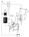
ここで図1を参照すると、本開示の原理に従って構成された超音波撮像システム100がブロック図の形式で示されている。超音波撮像システム100は、本願に記載されている任意の超音波撮像システムを少なくとも部分的に実現するために使用されることが可能である。図1は、超音波プローブ102、トランスデューサ・アレイ132、マイクロビームフォーマ130、送信/受信(T/R)スイッチ108、ビームフォーマ110、送信コントローラ114、信号プロセッサ112、Bモード・プロセッサ122、スキャン・コンバータ120、多断面再構成部126、ボリューム・レンダラ124、画像プロセッサ118、グラフィックス・プロセッサ116、ユーザー・インターフェース104、入力デバイス134、及び出力デバイス128を含む超音波撮像システム100を示す。図1に示される構成要素は単なる例示的なものであり、構成要素の削除、構成要素の組み合わせ、構成要素の再配置、及び構成要素の置換を含む他の変形例は全て想定されている。
Referring now to FIG. 1, an
図1の超音波撮像システム100において、超音波プローブ106は、超音波を送信し、エコー情報を受信するためのトランスデューサ・アレイ132を含む。種々のトランスデューサ・アレイ、例えば線形アレイ、凸状アレイ、又はフェーズド・アレイは、当技術分野でよく知られている。例えば、トランスデューサ・アレイ132は、2D及び/又は3D撮像のために、仰角方向及び方位角方向の両方でスキャンすることが可能なトランスデューサ素子の2次元アレイを含むことが可能である。トランスデューサ・アレイ132は、幾つかの場合において、典型的には超音波プローブ106内に配置されるマイクロビームフォーマ130に結合されることが可能であり、マイクロビームフォーマ130は、アレイ内のトランスデューサ素子による信号の送受信を制御する。図1に示す例では、マイクロビームフォーマ130は、例えばプローブ・ケーブル又はワイヤレスにより、送信及び受信の間で切り替わる送受信T/Rスイッチ108に結合される。従って、T/Rスイッチ108は、ビームフォーマ110を高エネルギー送信信号から保護することが可能である。幾つかの実施形態において、T/Rスイッチ108及びシステムの他の構成要素は、別個の超音波システム・ベースにあるのではなく、トランスデューサ・プローブ内に含まれることが可能である。
In the
特定の実施形態に存在する場合に、マイクロビームフォーマ130の制御の下で、超音波ビームのトランスデューサ・アレイ132からの送信は、T/Rスイッチ108及びビームフォーマ110に結合される送信コントローラ114によって指図される。送信コントローラ114は、ユーザー・インターフェース104の入力デバイス134のユーザーの操作から入力を受ける。入力デバイス134は、ソフト及び/又はハード制御を含むことが可能な制御パネル(例えば、タッチ・スクリーン、コンソール、又はこれら2つの組み合わせ)を用いて実現されることが可能である。送信コントローラ114によって制御される機能の1つは、ビームがステアリングされる方向である。ビームは、トランスデューサ・アレイからまっすぐ前方に(直角方向に)、又はより広い視野に対して様々な角度で、方向付けられることが可能である。マイクロビームフォーマを含む実施形態では、マイクロビームフォーマ130によって生成される部分的にビームフォーミングされた信号は、ビームフォーマ110に結合され、ここで、トランスデューサ素子の個々のパッチからの部分的にビームフォーミングされた信号が、完全にビームフォーミングされた信号に合成される。他の実施形態において、アレイ132からの信号は、アレイからの信号に応答してビームフォーミングされた信号を形成するビームフォーマ110に伝達される。
Transmission of ultrasound beams from
ビームフォーミングされた信号は、信号プロセッサ112に結合されることが可能である。信号プロセッサ112はまた、バンドパス・フィルタリング、デシメーション、I及びQ成分分離、及び高調波信号分離などの様々な方法で、受信したエコー信号を処理することも可能である。処理された信号は、Bモード・プロセッサ122につながることが可能であり、Bモード・プロセッサは、身体内の構造の撮像のために振幅検出を使用することができる。Bモード・プロセッサによって生成される信号は、3Dデータが取得される場合には、スキャン・コンバータ30及び多断面再構成部126につながることが可能である。スキャン・コンバータ120は、エコー信号をある空間的関係で整え、エコー信号はその空間的関係で所望の画像フォーマットで受信されている。例えば、スキャン・コンバータ120は、エコー信号を二次元(2D)セクター形状フォーマット、又はピラミッド状三次元(3D)画像に整えることができる。多断面再構成部126は、U.S.Pat.No.6,443,896(Detmer)に記載されているように、身体の体積領域内の共通平面内の点から受信されたエコーを、その平面の超音波画像に変換することができる。ボリューム・レンダラ124は、例えばU.S.Pat.No.6,530,885(Entrekin et al.)に記載されているように、3Dデータ・セットのエコー信号を、所与の基準点から眺めたような投影された3D画像に変換する。2D又は3D画像は、スキャン・コンバータ120、多断面再構成部126及びボリューム・レンダラ124から画像プロセッサ118につながり、出力デバイス128での表示のために、更なる強調、バッファリング及び一時記憶を行うことが可能である。出力デバイス128は、LCD、LED、OLED、又はプラズマ・ディスプレイ技術などの様々な既知のディスプレイ技術を用いて実現されるディスプレイ・デバイスを含んでもよい。
The beamformed signal may be coupled to signal
グラフィックス・プロセッサ116は、超音波画像と共に表示するためのグラフィック・オーバーレイを生成することができる。これらのグラフィック・オーバーレイは、例えば、患者名、画像の日付及び時刻、撮像パラメータなどの標準的な識別情報を含むことができる。グラフィックス・プロセッサは、入力デバイス134から、タイプされた患者名のような入力を受け取ることができる。入力デバイス134は、例えばボタン、ダイヤル、トラックボール、物理的なキーボードその他の1つ以上の機械的な制御部を含む可能性があり、これらは本願でハード制御部と言及される可能性がある。代替的又は追加的に、入力デバイス134は、ボタン、メニュー、ソフト・キーボード、及び、例えばタッチ・センシティブ技術(例えば、抵抗性、容量性、又は光学式のタッチ・スクリーン)を用いて実装される他のユーザー・インターフェース制御要素のような、1つ以上のソフト制御部を含んでもよい。この目的のために、超音波撮像システム100は、ユーザー・インターフェース・プロセッサ(即ち、プロセッサ140)を含んでもよく、これはソフト制御に関連する機能などのユーザー・インターフェースの動作を制御することが可能である。1つ以上のユーザー制御部は、制御パネル上に共に配置されてもよい。例えば、1つ以上の機械的な制御部がコンソール上に設けられることが可能であり、及び/又は1つ以上のソフト制御部が、コンソールに取り付けるか又はコンソールと一体化することが可能なタッチ・スクリーンに共に配置されることが可能である。
超音波画像及び関連するグラフィックス・オーバーレイは、例えばオフライン分析のためにメモリ136に記憶されてもよい。幾つかの実施形態では、メモリ136は、超音波システム・ベース内に設けられたローカル・メモリを含んでもよい。幾つかの実施形態では、メモリ136は、画像アーカイブ及び通信システム(PACS)の記憶装置を含んでもよい。幾つかの実施形態では、超音波画像及び関連データは、PACSサーバ上に局所的に及び遠隔的に何れによっても記憶されることが可能である。本願で説明されるように、メモリ136は、他の撮像システムから取得された画像を記憶してもよい。例えば、メモリ136は、別の超音波撮像システム、磁気共鳴撮像システム、及び/又はX線マンモグラフィ・システムによって取得された画像を記憶することができる。
The ultrasound images and associated graphics overlays may be stored in
更に、メモリ136は、ユーザー・インターフェース104に関連付けられた機能を実行するための命令を含むプロセッサ実行可能命令を格納することができる。ユーザー・インターフェース104はまた、多断面再構成(multiple multiplanar reformatted:MPR)画像の表示の選択及び制御のために、多断面再構成部126に結合されることが可能である。本願で説明されているように、メモリ136は、組織変形モデルに関連する機能を実行するための命令を含むプロセス実行可能命令を記憶することができる。幾つかの実施形態では、メモリ136は複数のメモリを含んでもよい。
Additionally,
幾つかの実施形態では、2つ以上の処理コンポーネント(例えば、ビームフォーマ110、信号プロセッサ112、Bモード・プロセッサ122、スキャン・コンバータ120、多断面再構成部126、ボリューム・レンダラ124、画像プロセッサ118、グラフィックス・プロセッサ116、プロセッサ140など)の機能は、単一の処理ユニットに統合されてもよいし、あるいは複数の処理ユニット間で分割されてもよい。例えば、プロセッサ140は、ユーザー・インターフェース・プロセッサ、及び変形モデル・プロセッサの2つのプロセッサを含むことが可能である。別の例では、グラフィックス・プロセッサ116及び画像プロセッサ118は、単一のプロセッサに統合されることが可能である。
In some embodiments, two or more processing components (e.g.,
本開示の原理によれば、センサ138は、超音波プローブ106に取り付けられることが可能であり、位置追跡システム106(例えば、電磁(EM)追跡システム)に動作可能に関連付けられることが可能であり、その結果、プローブの空間位置が追跡及び/又は記録されることが可能である。プロセッサ140は、被験者に対して超音波プローブ106を位置合わせし、位置追跡システム102から受け取った位置データに加えて、位置合わせ(レジストレーション)に基づいて、被験者に対するプローブの空間位置を決定するように構成されてもよい。プロセッサは、位置追跡プローブで取得された画像に位置データを関連付けるように更に構成されてもよい。
In accordance with the principles of the present disclosure,
本開示の原理によれば、プロセッサ140は、メモリ136に記憶されたもの等のような、別の撮像システムによって取得された画像及び/又は画像に関連するデータを受信するように構成及び/又は更に構成されることが可能である。プロセッサ140は、受信した画像及び/又はデータに少なくとも部分的に基づいて組織変形モデルを適用し、組織内の対象物(例えば、病変、解剖学的ランドマーク)の予測位置を生成するように構成されることが可能である。プロセッサ140は、予測位置を画像プロセッサ118、グラフィックス・プロセッサ116、メモリ136、及び/又はユーザー・インターフェース104に提供することができる。
In accordance with the principles of the present disclosure,
プロセッサ140は、メモリ136から変形モデルの命令を受け取ることができる。幾つかの実施形態において、プロセッサ140は、ユーザー入力デバイス134を介して、ユーザー(例えば、臨床医)から追加データを受信してもよい。例えば、ユーザーは、寸法(例えば、乳房幅、体積)及び/又は組織構成(例えば、脂肪、腺、筋肉)に関するデータを提供する可能性がある。幾つかの実施形態において、プロセッサ140は、セグメンテーション・モデルを、受信した画像に適用し、組織の組成及び/又は寸法を決定してもよい。別の例では、ユーザーは、別の撮像システムによって取得された画像における病変の位置を示す可能性がある。更なる例において、ユーザーは、適用する変形モデルのタイプ(例えば、仰臥位から腹臥位へ、圧縮から非圧縮へ)を指定してもよい。
幾つかの実施形態において組織変形モデルを実装するために使用されることが可能な組織変形モデルの一例は次の文献に示されている:米国特許出願番号13/666,600,“Apparatus and methods of compensating for organ deformation of internal structures to images, and applications of same”(Miga, et al.)。組織変形モデルは、幾つかの実施形態において、胸部変形モデルであってもよい。組織変形モデルを実装するために使用することができる胸部変形モデルの一例は次の文献にも記載されている:米国特許出願第14/000,068号,“System and method for providing registration between breast shapes before and during surgery”(Barth, et al)。幾つかの実施形態において使用することが可能な胸部変形モデルの他の例は、次の文献に記載されている:
“Breast Deformation Modelling: Comparison of Methods to Obtain a Patient Specific Unloaded Configuration,” Eiben, B., et al., Medical Imaging 2014: Image-Guided Procedures, Robotic Interventions, and Modeling, Proc. Of SPIE Vol. 9036, 903615、及び
“Biomechanically Guided Prone-to-Supine Image Registration of Breast MRI Using an Estimated Reference State,” Eiben, B., et al., 2013 IEEE 10th International Symposium on Biomedical Imaging: From Nano to Macro, San Francisco, CA, USA, April 7-11, 2013。
これらの組織変形モデルは例示の目的のためだけに提供されている。本開示の原理は引用された例に限定されない。
An example of a tissue deformation model that may be used to implement the tissue deformation model in some embodiments is shown in U.S. Patent Application No. 13/666,600, “Apparatus and methods of compensating for organ deformation of internal structures to images, and applications of the same” (Miga, et al.). The tissue deformation model may be a chest deformation model in some embodiments. An example of a breast deformation model that can be used to implement a tissue deformation model is also described in U.S. Patent Application No. 14/000,068, “System and Method for Providing Registration Between Breast Shapes. “before and during surgery” (Barth, et al). Other examples of chest deformation models that may be used in some embodiments are described in the following documents:
“Breast Deformation Modeling: Comparison of Methods to Obtain a Patient Specific Unloaded Configuration,” Eiben, B. , et al. , Medical Imaging 2014: Image-Guided Procedures, Robotic Interventions, and Modeling, Proc. Of SPIE Vol. 9036, 903615, and “Biomechanically Guided Prone-to-Supine Image Registration of Breast MRI Using an Estimated Reference State,” Eiben, B. , et al. , 2013 IEEE 10th International Symposium on Biomedical Imaging: From Nano to Macro, San Francisco, CA, USA, April 7-11, 20 13.
These tissue deformation models are provided for illustrative purposes only. The principles of this disclosure are not limited to the examples cited.
図2は、本開示の原理による乳房撮像に使用されることが可能な超音波撮像システムの図を示す。図2は、超音波撮像システム200、超音波撮像デバイス202、プローブ204、ディスプレイ206、ライブ画像208、位置追跡システム210、患者212、ユーザー・インターフェース216、関節アーム218、タッチ・スクリーン220、ベース222、及び病変位置インターフェース224を示す。図2に示される構成要素は単なる例示的なものであり、構成要素の削除、構成要素の結合、構成要素の再配置、及び構成要素の置換を含む他の変形例は全て想定されている。
FIG. 2 shows a diagram of an ultrasound imaging system that can be used for breast imaging according to the principles of the present disclosure. FIG. 2 shows an
超音波撮像システム200は、図1の超音波撮像システム100の構成要素のうちの1つ以上を含む可能性がある。超音波撮像システム200は、カート・ベースの超音波撮像デバイス、ハンドヘルド撮像デバイス、又は他のポータブル撮像デバイスであってもよい超音波撮像デバイス202を含むことが可能である。例えば、超音波撮像デバイス202のうちの1つ以上の処理構成要素(例えば、ビームフォーマ、メモリ、信号プロセッサ、Bモード・プロセッサ、スキャン・コンバータ、多断面再構成部、ボリューム・レンダラ、画像プロセッサ、グラフィックス・プロセッサ、及び/又は、超音波撮像デバイスの様々な動作を制御することが可能な他のプロセッサ)は、移動ベースであってもよいベース222内に設けられてもよい。超音波撮像システム200は、ディスプレイ206を含んでもよい。ディスプレイ206は、表示される画像が、(例えば、患者、別の超音波臨床医、又は臨床医のような)他者によって眺められることを可能にする等のためにディスプレイ206を再配置するために、関節アーム218を介してベース222に取り付けられることが可能である。
超音波撮像デバイス202は、有線接続(例えば、ケーブル)又は無線接続(例えば、Wi-Fi)を介してプローブ204に接続されてもよい。プローブ204は、被験体(例えば、患者212)の乳房組織をスキャンするために使用されることが可能である。プローブ204は、フリーハンド操作用に構成されてもよい。フリーハンドによりとは、一般に、プローブが、機械制御されるアクチュエータによってではなく、臨床医(例えば、超音波技師、放射線技師)によって取り扱われる(例えば、移動される)ことを意味する。プローブ204の動作は、ユーザー・インターフェース216を介して部分的に制御されてもよい。ユーザー・インターフェース216は、機械的及びソフト的な制御部などの入力コンポーネント、そして、視覚的、聴覚的、及び触覚的なフィードバック・デバイスなどの出力コンポーネントを含む可能性がある。ユーザー・インターフェース216のうちの1つ以上の構成要素は、ディスプレイ206、タッチ・スクリーン220、又はそれらの組み合わせに設けられることが可能なグラフィカル・ユーザー・インターフェース(GUI)要素を用いて実現されることが可能である。例えば、プローブ204で取得された画像(例えば、ライブ画像208)は、ディスプレイ206上で、タッチ・スクリーン220上で、又はその両方で表示されてもよい。超音波撮像システム200及び/又は別の撮像システム(例えば、MR撮像システム)によって事前に取得された画像は、ディスプレイ206、タッチ・スクリーン220、又はその両方に提供されてもよい。幾つかの実施形態では、以前に取得された画像が、ライブ画像208と同時に表示されてもよい。ユーザー・インターフェースは、超音波システムの動作を制御するためのGUI要素を提供するように構成されることが可能である。例えば、1つ以上のGUI制御部は、タッチ・スクリーン220に設けられることが可能である。
ユーザー・インターフェース216は、病変位置インターフェース224を含むことが可能である。病変位置インターフェース224は、異なる撮像システム(例えば、MRシステム)からの画像において以前に発見された病変の位置を、臨床医が突き止めることを支援するために、1つ以上のユーザー・インターフェース要素を提供することが可能である。病変位置インターフェース224の1つ以上の要素は、ディスプレイ206、タッチ・スクリーン220、又はそれらの組み合わせにおいて提供されることが可能なGUI要素として実装されることが可能である。病変位置インターフェース224の1つ以上の要素は、1つ以上のインターフェース・ウィンドウ内に、同時に又は異なる時間に提供されてもよい。
病変位置インターフェースは、タッチ・スクリーン220上に設けられるGUI制御部を含む位置制御部を含んでもよく、その具体例を以下で更に説明する。従来のワークステーション等の幾つかの実施形態において、位置制御部は、マウス、トラックボール、タッチ・パッド、キーボードなどの従来の入力デバイスに応答するGUI制御部を使用して実現されることが可能である。位置制御部は、ユーザーが、以前に取得された画像データ(例えば、MRのような第1モダリティを使用して取得された画像データ)に対する疑わしい病変位置の指示を提供できるようにすることが可能であり、この場合、疑わしい位置は、組織を超音波スキャンする場合に病変の予測位置を生成するために使用されることが可能である。予測される病変位置は、2つの撮像モダリティの患者姿勢の相違を考慮した変形モデルに基づいて生成されることが可能である。予測される病変位置は、例えば、病変位置インターフェース224の解剖学的代表図形において、予測病変位置の図式表現を提供することによって、後続の超音波スキャンをガイドするために使用されることが可能である。病変位置インターフェース224は、超音波システムのディスプレイ、ワークステーションのディスプレイ、又は別のディスプレイ上に表示されることが可能な図形を含んでもよい。図形は、例えば、解剖学的に代表的な図形226(ボディ・マークとも呼ばれる)の上又は隣にマーキング228を表示することによって、解剖学的にインテリジェントな方法で情報(例えば、予測される病変位置の指標であるとすることが可能な1つ又は複数のマーキング)を表示するように構成されることが可能である。解剖学的代表図形226は、解剖学的な部分又は器官の二次元又は三次元的な描画を含んでもよい。この文脈において、解剖学的にインテリジェントとは、代替的又は追加的に、解剖学的代表図形におけるマーキング228の自動配置を指す可能性があり、そのマーキングは、変形モデルによって調整される、以前に取得されたデータ・セットにおける病変についての指示された被疑位置に基づいて、病変の予測位置を示すことができる。上述したように、画像データは位置追跡プローブにより取得されることが可能であり、従って、解剖学的にインテリジェントとは、代替的又は追加的に、特定の画像(例えば、解剖学的構造に関するプローブの現在の位置及び/又は角度、プローブの示唆される位置及び/又は角度、及び/又はそれら両者の組み合わせを示す図形)の取得中に、プローブの位置に基づいてボディ・マーク226上にマーキング228を自動配置することを指す可能性がある。図示される例では、解剖学的に代表的な図形226は、撮像された乳房に対応する側の乳房を示す乳房図形であってもよい。乳房図形は、更に説明されるように、1つ以上のマーキング228と重ね合わせられてもよい。また、マーキング228は隣に(例えば、ボディ・マークの上、下、又は任意の側に)配置されてもよい。マーキング228(例えば、シンボル及び/又はインジケータ)は、英数字記号及び/又は幾何学的形状を含んでもよい。幾つかの実施形態では、図形226は、解剖学的に代表的なものではなく、代わりに、クロック・ダイアグラムにおいて、マークが重ねられているもの、又はクロック・ダイアグラムに隣接して提供されているものであってもよい。
The lesion location interface may include location controls, including GUI controls provided on
超音波撮像システム200は、位置追跡システム210と動作可能に関連付けられることが可能である。位置追跡システム210は、電磁(EM)追跡システムであってもよい。EM追跡システムは、典型的には、EMフィールド発生器及びセンサを含む。センサは、プローブ204に取り付けられることが可能である(例えば、プローブ204のハウジングの内側又は外側に埋め込まれる)。幾つかの実施形態において、タブレットEMフィールド発生器が使用されてもよい。EMフィールド発生器は、被験者を支持する支持面(例えば、検査テーブル)に対して、従って患者に対して可動であってもよい。これは、スキャンされるべき臓器又は組織(例えば、左乳房、右乳房)をEM電磁場が包含するように、EMフィールド発生器の再配置を可能にすることができる。幾つかの実施形態において、EMフィールド発生器は、支持表面に対して固定されてもよい。他の実施形態では、光学追跡システム(例えば、ビデオ、赤外線)などの異なるタイプの位置追跡システムが使用されてもよい。
位置追跡プローブで取得される撮像データは、超音波撮像システム200のプロセッサが、そこから生成される超音波画像の中で対象物の相対位置を決定することを可能にすることができる。例えば、超音波撮像システム200のプロセッサは、位置追跡システム210からの位置データを使用して、患者212に対するプローブの空間位置を推定することが可能であり、その位置データは、位置追跡プローブ(例えば、プローブ204)で取得された画像から関連情報を抽出することを促進することができる。例えば、超音波撮像システムは、位置追跡プローブで取得された画像を、別の撮像システムによって取得された画像及び/又は以前の超音波検査中に取得された画像と相関させることが可能である。プローブ位置データは、3D空間におけるプローブの位置及び方向のような、プローブに関する位置情報を含んでもよい。超音波撮像システム200は、ユーザーが、プローブ204を患者の解剖学的構造に関して位置合わせすることを可能にすることができる。例えば、超音波撮像システム200は、関連する解剖学的ランドマーク(例えば、乳房の乳頭、乳房の境界など)に配置される場合に、プローブの空間位置を、それぞれのランドマークに関連付けるように構成されてもよい。
Imaging data acquired with the position tracking probe may enable a processor of
説明されているように、超音波撮像デバイス202は、MRシステムなどの別の撮像システムから取得された画像を受信してもよい。受信した画像は、超音波撮像デバイス202に含まれるメモリに記憶されてもよい。幾つかの実施形態では、受信した画像及び/又は超音波撮像システム200によって取得された超音波画像は、対応する病変位置及び/又はプローブ位置データを付加した標準フォーマット(例えば、DICOMフォーマット)に従って、単一又は複数フレームの画像ファイルに記憶されてもよい。幾つかの実施形態において、病変位置は、例えば、クロック角度、乳頭からの距離、及び皮膚ラインからの深さを用いて記載されることが可能である。幾つかの実施形態では、臨床医は、受け取った画像をディスプレイ206及び/又はタッチ・スクリーン220上で眺め、受け取った画像内で病変位置情報を示すマーキングを、ユーザー・インターフェース216により追加することができる。幾つかの態様において、臨床医は更に、画像上に組織の種類及び/又は構成を示してもよい。例えば、臨床医は、組織タイプ及び/又は構成を示すために、他の撮像システムから受信した画像の様々な領域を手動で区分してもよい。
As described,
以前のモダリティから受信した画像データは、場合によっては、疑わしい病変位置マーキングを示す情報を含んでいてもよく、超音波撮像デバイス202に含まれるプロセッサに提供されてもよい。プロセッサは、組織変形モデルを、受信した画像データに適用し、1つ以上の予測病変位置を決定してもよい。予測病変位置は、病変位置インターフェース224を介して、例えばボディ・マーク226上で病変228についての最も可能性が高い位置を示す図形により、臨床医に提供されることが可能である。幾つかの実施形態において、プロセッサはまた、病変を超音波撮像するために、解剖学的構造に関連してプローブの示唆される配置(例えば、乳首又は他の解剖学的ランドマークに関連する超音波プローブ204の位置及び/又は角度)を決定してもよい。
Image data received from the previous modality, which may optionally include information indicative of suspected lesion location markings, may be provided to a processor included in
超音波画像システム200は、病変位置インターフェース224、他の撮像モダリティからインポートされた画像又はデータ・セット、及び/又はライブ超音波画像208を同時に表示することができる。臨床医は、検査中に得られた超音波画像を保存及び/又は注釈することができる。ユーザーはまた、検査中に、(例えば、MRから)インポートされたデータに異なる病変をマークし続けることが可能である。幾つかの実施形態では、以前に取得された画像データからの画像は、ユーザーが疑わしい病変位置に印を付けることができるように同時に表示され、即ちその位置は、第2撮像モダリティ(この場合は、超音波)のための予測病変位置を生成するために使用される。受信された画像に対する追加のマーキングは、予測された病変位置を修正するためにプロセッサによって使用されることが可能であり、修正された予測は、病変位置インターフェース224上で更新されることが可能である。
The
病変が超音波プローブ204で突き止められている場合、臨床医は、病変の実際の位置に関して超音波画像を注釈することが可能である。病変の実際の位置が予測位置と異なる場合、病変位置インターフェース224内の病変予測図形は、病変の実際の位置を示すように更新されることが可能である。幾つかの実施形態において、病変の実際の位置及び予測される位置は、病変位置インターフェース224によって同時に表示されてもよい。これにより、位置決めされるべき追加の病変の予測位置がどの程度不正確であり得るかに関する推定を、臨床医に提供することができる。幾つかの実施形態において、病変の実際の位置は、プロセッサに提供されてもよい。プロセッサは、予測された病変位置と実際の病変位置との間の差分を使用して、変形モデルを適応的に修正することができ、変形モデルの精度を改善することができる。
If a lesion is located with the
超音波検査中に病変の位置が特定されると、臨床医はその寸法や及び/又は他の特性(例えば、凝り)を測定する可能性がある。これらの追加の測定値は、スクリーン上に表示され、画像及び/又は画像のセット(例えば、シネループ)と共に保存されることが可能である。臨床医はまた、病変の生検をガイドするために超音波撮像システム200を使用してもよい。超音波画像、関連する測定及び/又は病変位置(例えば、実際の病変位置、予測される病変位置)は、超音波画像システム200のメモリに記憶されてもよい。画像及び/又は注釈は、超音波撮像システムによって自動的に、及び/又は臨床医による入力に応答して保存されてもよい。超音波画像及び/又は注釈は、超音波検査の後に再検討される可能性がある。
Once a lesion is located during an ultrasound examination, the clinician may measure its size and/or other characteristics (eg, stiffness). These additional measurements can be displayed on the screen and saved with the image and/or set of images (eg, cine loop). Clinicians may also use
本開示の原理によれば、超音波撮像システムのユーザー・インターフェース(例えば、ユーザー・インターフェース216)は、変形モデルによって決定された予測病変位置に基づいて予測病変位置の視覚的な指標を提供するように構成されてもよい。予測病変位置は、別の撮像システムによって取得された画像における病変位置のマーキングに少なくとも部分的に基づいて決定されていてもよい。幾つかの実施形態において、予測病変位置の視覚的な表示は、関連する病変位置情報(例えば、1つ以上の位置インジケータ、注釈、又は他のもの)と重ね合わされたボディ・マークを表示することによって提供されることが可能である。幾つかの実施形態において、ボディ・マークは、示唆される超音波プローブの位置及び/又は角度、又は位置追跡に基づく超音波プローブの実際の位置を表すラインと重ね合わせられることが可能である。 In accordance with the principles of the present disclosure, a user interface (e.g., user interface 216) of an ultrasound imaging system is configured to provide a visual indication of a predicted lesion location based on the predicted lesion location determined by the deformation model. may be configured. The predicted lesion location may have been determined based at least in part on markings of the lesion location in images acquired by another imaging system. In some embodiments, the visual display of the predicted lesion location includes displaying a body mark overlaid with associated lesion location information (e.g., one or more location indicators, annotations, or other). It can be provided by In some embodiments, the body mark can be superimposed with a line representing the suggested position and/or angle of the ultrasound probe or the actual position of the ultrasound probe based on position tracking.
図3及び図4も参照して、本開示の原理に従ったユーザー・インターフェース要素の例が更に説明される。ユーザー・インターフェースは病変位置インターフェースを提供するように構成されてもよく、病変位置インターフェースは、病変の位置を特定し、乳房超音波画像を取得及び/又は注釈付けし、及び/又は別の撮像システムから受信した画像上で病変位置をマーキングするための1つ以上のユーザー・インターフェース要素を含むことが可能である。例えば、病変位置インターフェースは、乳房超音波検査の場合には乳房図形であってもよいボディ・マークを表示するように構成されてもよい。乳房図形は、撮像及び/又は特徴付けられる対応する乳房の側のイラストを提供することが可能であり、例えば、右乳房を撮像又は特徴付ける場合には右乳房図形が表示される可能性があり、左乳房を撮像又は特徴付ける場合には左乳房図形が表示される可能性がある。ボディ・マークは、個々の予測される及び/又は実際の病変位置、又は1つ以上の予測される病変位置の領域に関連する1つ以上のインジケータのような、関連する病変位置情報と重ね合わせられてもよい。 Referring also to FIGS. 3 and 4, examples of user interface elements in accordance with the principles of the present disclosure are further described. The user interface may be configured to provide a lesion location interface for locating a lesion, acquiring and/or annotating breast ultrasound images, and/or using another imaging system. may include one or more user interface elements for marking a lesion location on an image received from the user interface. For example, the lesion location interface may be configured to display a body mark, which may be a breast shape in the case of a breast ultrasound. The breast figure may provide an illustration of the side of the corresponding breast being imaged and/or characterized, for example, if the right breast is imaged or characterized, the right breast figure may be displayed; When imaging or characterizing the left breast, a left breast shape may be displayed. The body marks are overlaid with associated lesion location information, such as one or more indicators related to the respective predicted and/or actual lesion locations or regions of one or more predicted lesion locations. It's okay to be hit.
図3は、本開示の原理による病変位置インターフェース300に関連するユーザー・インターフェース要素を示す。図3は、病変位置インターフェース300、受信画像302、ライブ画像304、ボディ・マーク306及び308それぞれを示す。病変位置インターフェース300の1つ以上の要素は、ディスプレイ206のような超音波撮像システムのディスプレイで表示されることが可能である。病変位置インターフェース300の1つ以上の要素は、追加的又は代替的に、超音波撮像システム200のタッチ・スクリーン220のようなタッチ・スクリーン上に表示されてもよい。病変位置インターフェース300の要素は、同時に又は順番に提供されてもよく、1つ以上のインターフェース・ウィンドウに配置されてもよい。更に、図3には示されていないが、病変位置インターフェース300は、例えば超音波撮像システム200のタッチ・スクリーン220上で提供されることが可能な、レイアウト、図形、及び注釈ボタンのような1つ以上のユーザー制御部を提供してもよい。ユーザー・インターフェース要素の特定の例又は配置は、例示であるに過ぎず、本開示の範囲から逸脱することなく、他の実施例(例えば、ハード制御部、ソフト制御部)又は要素の配置が使用されることが可能である。図2の例では、病変位置インターフェース300のうちの1つ以上の要素が、病変位置インターフェース224を実現するために使用されることが可能である。
FIG. 3 illustrates user interface elements associated with a
受信画像302は、臨床医が超音波検査中に探している病変を含む、別の撮像システムからの画像であるとすることが可能である。幾つかの実施態様において、受信画像302は、別のモダリティにおいて乳房から取得されたボリューム・データ・セットからの単一スライスである。ユーザーは、所望のスライスが表示されるまで、ボリューム・データ・セット内の様々なスライスを手動でスクロールすることが可能である。その時点で、ユーザーは、スライス上で関心のある病変がある場所を指示することが可能である。他の実施形態において、ボリューム・データがライブ超音波画像に対して部分的に位置合わせされる場合、受信画像302は、受信した画像のセットのうち、臨床医が超音波画像システムで現在撮像している組織内の位置に対応する画像(例えば、ボリュームのスライス)であるとすることが可能である。即ち、超音波プローブ内の位置追跡は、組織内でどこからライブ画像304が取得されているかを決定することができる。その位置はプロセッサに提供されることが可能であり、プロセッサは対応する受信画像302を表示のために取り出すことができる。
ボディ・マーク306は、病変の予測された位置を解剖学的構造上に示す注釈を含んでもよい。図3に示す例では、影の付いた楕円形は、病変が突き止められているように予測される乳房の領域を示す。臨床医に予測位置を提供することは、超音波検査中にインテロゲーションを行う体積、及び/又は病変の位置を突き止めるために必要とされる時間を減らすことが可能である。幾つかの実施形態において、図3には示されていないが、ボディ・マーク306は、病変を特定するための超音波プローブの位置及び/又は角度を示唆するために、追加のインジケータを含んでもよい。
Body marks 306 may include annotations indicating the predicted location of the lesion on the anatomy. In the example shown in FIG. 3, the shaded oval indicates the region of the breast where the lesion is predicted to be located. Providing a clinician with a predicted location can reduce the volume interrogated during an ultrasound examination and/or the time required to locate a lesion. In some embodiments, although not shown in FIG. 3, the
ライブ画像304は、超音波プローブによって現在取得されている画像であってもよい。幾つかの実施形態では、ライブ画像304は、臨床医によって保存された超音波画像によって置き換えられてもよい。例えば、臨床医は、超音波画像又は画像(複数)を取得し、検査を一時停止して、取得した画像に注釈を追加する可能性がある。注釈は、病変の実際の位置、病変の寸法、及び/又は病変の他の特性(例えば、凝り)に印を付けることを含んでもよい。画像及び/又は注釈は、後のレビューのために超音波撮像システムのメモリに保存されてもよい。画像の取得及び/又は注釈付けの後、臨床医は、ライブ画像の取得に戻ってもよいし、あるいは検査を終了してもよい。
ボディ・マーク308は、ボディ・マーク306と同様に、解剖学的構造において病変の予測位置がどこにあるかを示す注釈を含んでもよい。幾つかの実施形態において、図3に示すように、ボディ・マーク308は、超音波プローブの現在の位置及び/又は角度を示す追加の図形を含んでもよい。幾つかの実施形態にでは、ボディ・マーク306又は308のみが提示される。
超音波検査中に複数の病変が特定されるべき場合、病変位置インターフェース300は、特定されるべき全ての病変に対して、予測位置の視覚的指標を提供することができる。代替的に、病変位置インターフェース300は、一度に1つの病変の予測位置を提供することができる。臨床医は、複数の病変の予測位置の間でトグル方式で切り替えを行うことができる。幾つかの実施形態では、病変位置インターフェース300は、一群の病変のうちのどの病変が臨床医によって現在位置決めされているか(例えば、2つのうちの1つ、4つのうちの3つ)の指標を提供してもよい。これは、全ての病変が突き止められる前に、臨床医が検査を終了してしまう可能性を減らすことが可能である。病変の実際の位置が臨床医によって注釈付けされる場合、病変位置インターフェース300は、実際の位置を、受信画像からの特定の病変に自動的に関連付けることが可能であり、及び/又は臨床医は、受信画像中のどの病変が、実際の位置に関連付けられるかを手動で示すことができる。
If multiple lesions are to be identified during an ultrasound examination, the
図4は、本開示の原理によるボディ・マーク及び関連する注釈を示す。ボディ・マーク400は、病変の予測位置を示す注釈402を含む。同様に、ボディ・マーク404は、複数の病変の予測位置を示す注釈406a及び406bを含む。注釈402、406a、及び406bは円として示されているが、他の注釈(例えば、X、四角形、数字)が使用されてもよい。ボディ・マーク408は、病変の1つ以上の予測位置が突き止められる領域の影付き楕円体である注釈410を含む。ボディ・マーク412は、領域内の病変の予測される位置及び実際の位置をそれぞれ示す注釈414及び416を含む。実際の位置は、超音波撮像システムのユーザー入力デバイスにより、臨床医が追加してもよい。注釈410及び414は楕円体として示されているが、他の地域インジケータ(例えば、四分円、放射状セグメント)が使用されてもよい。ボディ・マーク418は、病変の1つ以上の予測位置が突き止められている領域を示す注釈420と、病変を可視化するための提案されるプローブ位置を示す注釈422とを含む。ボディ・マーク424はまた、病変の1つ以上の予測される位置が突き止められる領域と、病変を可視化するための提案される超音波プローブ位置とをそれぞれ示す注釈426及び428を含む。更に、ボディ・マーク424は、超音波プローブの現在位置を示す注釈430を含む。現在の位置は、本願で説明されるようなプローブ追跡システムによって提供されてもよい。注釈430は、臨床医が超音波プローブを動かすにつれて、ボディ・マーク424上で更新されてもよい。図4に示されているボディ・マーク及び注釈は、例えば目的のためだけに提供されている。他のタイプの注釈及び/又は注釈の組み合わせが提供されてもよい。幾つかの実施形態において、臨床医は、ボディ・マーク上に如何なる注釈が提供されるかを、ユーザー・インターフェースにより選ぶことができる。
FIG. 4 illustrates body markings and associated annotations in accordance with the principles of the present disclosure.
本願で説明される超音波撮像システムは、事前に取得した画像に変形モデルを適用し、予測される病変位置を表示し、ライブの超音波画像を取得し、ライブの超音波画像を表示することができる。超音波撮像システムは、以前に取得した画像を表示してもよい。検査中、超音波撮像システムは、ユーザー入力デバイスから実際の病変位置を受信し、実際の病変位置を、検査を実行する臨床医に表示することができる。実際の病変位置及び実際の病変位置に関連するライブ超音波画像は、超音波撮像システムに記憶されてもよい。これは、臨床医による入力に応答して行われてもよいし、或いは幾つかの実施形態では自動的に行われてもよい。 The ultrasound imaging system described in this application applies a deformation model to previously acquired images, displays the predicted lesion location, acquires a live ultrasound image, and displays the live ultrasound image. Can be done. The ultrasound imaging system may display previously acquired images. During the exam, the ultrasound imaging system can receive the actual lesion location from the user input device and display the actual lesion location to the clinician performing the exam. The actual lesion location and live ultrasound images associated with the actual lesion location may be stored in the ultrasound imaging system. This may be done in response to input by the clinician, or in some embodiments automatically.
超音波撮像システムは、本願で説明される1つ以上の方法を実行する可能性がある。例えば、超音波撮像システムの少なくとも一部分(例えば、プロセッサ)によって実行される方法は、注釈の付いた画像(例えば、印が付された病変位置を伴うMRボリューム)を受信するステップと、変形モデル・タイプ(例えば、仰臥位から腹臥位へ)を受信するステップと、注釈付き画像に変形モデルを適用し、予測される病変位置を生成するステップと、予測病変位置を病変位置インターフェース(例えば、病変位置インターフェース224)に提供するステップとを含むことが可能である。 An ultrasound imaging system may perform one or more of the methods described herein. For example, a method performed by at least a portion (e.g., a processor) of an ultrasound imaging system includes the steps of receiving an annotated image (e.g., an MR volume with marked lesion locations); applying a deformation model to the annotated image to generate a predicted lesion location; and transferring the predicted lesion location to a lesion location interface (e.g., lesion a location interface 224).
図5は、現在の超音波検査において、以前に取得された画像で判明している病変の位置を突き止める本開示の原理による例示的なプロセスのフローチャート500である。ステップ502において、臨床医は、以前に取得された画像を、超音波撮像システム(例えば、超音波撮像システム100又は超音波撮像システム200)にロードすることができる。以前に取得された画像は、MR撮像システム又は3D乳房トモシンセシス・システムによって取得されていてもよい。ステップ504において、臨床医は、超音波撮像システムのディスプレイ上で、ロードされた画像を検討し、ユーザー・インターフェースにより、疑わしい病変の位置に関して画像に印を付けることができる。画像が既に病変マーキングを含む場合、ステップ504は省略されてもよい。臨床医は、ステップ506で組織特性(例えば、組成、寸法)を入力することができ、組織特性は、受信画像の中で腺組織を含む領域、及び脂肪組織を有する他の領域、並びに胸壁及び胸壁筋肉の位置を識別することを含むが、これらに限定されない。あるいは、超音波撮像システムは、ステップ506において、組織特性を決定するために、ロードされた画像を自動的に処理してもよい。ステップ508において、適用する組織変形モデルが選択されてもよい。例えば、ロードされた画像がMR撮像システムによって取得されていた場合、腹臥位から仰臥位への変形モデルが選択されてもよい。本開示の幾つかの実施形態において、臨床医は、適用する組織変形モデルを選択してもよい。本開示の幾つかの他の実施形態において、適用する組織変形モデルは、超音波撮像システムによって自動的に選択されてもよい。
FIG. 5 is a
超音波撮像システムが変形モデルを適用した後、ステップ510において、臨床医は、予測される病変位置の視覚的指標を眺めることができる。幾つかの実施形態において、予測される病変位置は、病変位置インターフェースを含むディスプレイで提供されてもよい。ステップ512において、臨床医は、超音波プローブで1つ以上の超音波画像を取得してもよい。臨床医が画像を取得する位置は、ディスプレイ上に提供された予測病変位置に少なくとも部分的に基づくことが可能である。病変が発見された場合、ステップ514において、臨床医は、実際の病変の位置を示すために超音波画像に注釈を付けることができる。幾つかの実施形態において、臨床医は、画像及び/又は注釈を保存してもよい。幾つかの実施形態において、画像及び/又は注釈は自動的に保存されてもよい。望まれる場合には、ステップ516において、臨床医は、病変に関して測定を行ってもよく(例えば、寸法、特性)、及び/又は追加的な注釈を付加してもよい。幾つかの実施形態において、臨床医は、病変を生検してもよい。生検は超音波画像によって案内されてもよい。以前に取得した画像の中で複数の病変が検出された場合、各々の病変についてステップ510~516が反復されてもよい。
After the ultrasound imaging system applies the deformation model, at step 510, the clinician can view a visual indicator of the predicted lesion location. In some embodiments, the predicted lesion location may be provided on a display that includes a lesion location interface. At step 512, the clinician may acquire one or more ultrasound images with an ultrasound probe. The location at which the clinician acquires the image may be based at least in part on the predicted lesion location provided on the display. If a lesion is found, at
図6は、本開示の原理に従って病変の予測位置を決定するプロセスのフローチャート600である。図6に示されるプロセスは、幾つかの実施形態では、プロセッサ(例えば、プロセッサ140)によって実行されてもよい。幾つかの実施形態において、フローチャート600におけるプロセスを実行するための命令は、プロセッサにアクセス可能なメモリに、プロセッサ実行可能命令として格納されてもよい。ステップ602において、1つ以上の注釈付き画像及び/又は画像データが受信されることが可能である。受信した画像は、以前に取得した画像に対応する場合がある。注釈は病変位置情報を含む場合がある。以前に取得された画像は、別の撮像システムによって取得されていてもよい。
FIG. 6 is a
ステップ604において、画像は組織特性(例えば、サイズ、組成)を抽出するためにセグメント化及び/又は他の方法で処理されることが可能である。あるいは、ステップ606において、例えば、ユーザー入力デバイスにより臨床医が提供するようにして、組織特性が受け入れられてもよい。幾つかの実施形態において、ステップ604及び606の両方が実行されてもよい。即ち、ある組織特性は画像を分析することによって決定される可能性がある一方、別の他の組織特性は受信される。ステップ608において、組織変形モデル・タイプが受信されてもよい。変形モデル・タイプは、どの変形モデルを適用するか(例えば、腹臥位から仰臥位へ)を指定することができる。幾つかの実施形態において、変形モデル・タイプは、臨床医がユーザー入力デバイスによって提供してもよい。他の実施形態では、変形モデル・タイプは、受信された画像と共に記憶された取得情報に基づいて決定されてもよい。ステップ604、606、及び608は、順番に示されているが、それらは、異なる順番で又は同時に実行されることが可能である。例えば、ステップ608はステップ604の前に実行されてもよい。
At
ステップ610において、組織変形モデルが受信画像に適用され、病変の予測位置を決定することができる。幾つかの実施形態では、組織変形モデルは乳房変形モデルであってもよい。使用され得る変形モデルは、図1に関連して提供される例(例えば、米国特許出願第13/666,600号及び第14/000,068号)を含むが、これに限定されない。変形モデルによって決定される予測された病変位置は、超音波検査中に病変が存在し得る場所に対応する可能性がある。ステップ612において、予測された病変位置は、病変位置インターフェース、メモリ、ディスプレイ、グラフィックス・プロセッサ、画像プロセッサ、及び/又はそれらの組み合わせに提供されることが可能である。ステップ614において、提案された超音波プローブの位置及び/又は角度が提供されてもよい。提案される位置及び/又は角度は、予測された病変位置に少なくとも部分的に基づいている可能性がある。幾つかの実施形態において、ステップ614は省略されてもよい。
At
オプションとして、ステップ616において、実際の病変位置が受信されてもよい。実際の病変位置は、超音波撮像システムで取得される超音波画像に基づいて臨床医によって入力されてもよい。ステップ618において、ステップ610で適用される変形モデルが、実際の病変位置に少なくとも部分的に基づいて修正されてもよい。実際の病変部位に基づく変形モデルの修正は、変形モデルの精度を改善する可能性がある。幾つかの実施形態において、変形モデルは、実際の病変位置が予測位置の外側にある場合、及び/又は予測病変位置から離れた閾値距離の範囲外にある場合(例えば、100mmを超える、500mmを超える、1cmを超える場合)に限って修正されてもよい。閾値距離は、変形モデル及び/又は臨床医によって設定されてもよい。ステップ618の後、変形モデルは既存のデータに再適用されてもよいし、及び/又は、変形モデルは将来の超音波検査のために修正されてもよい。
Optionally, at
図7は、本開示の原理による超音波撮像システムで病変位置の視覚的指標を提供するためのプロセス700のフローチャートである。幾つかの実施形態では、プロセス700は、少なくとも部分的に、病変位置インターフェース(例えば、病変位置インターフェース224)によって実行されてもよい。ステップ702において、以前に取得された画像が表示されることが可能である。以前に取得された画像を表示することは、臨床医が、病変位置及び/又は他の情報で画像に印を付けることを可能にすることができる。幾つかの実施態様において、以前に取得された画像は、既に病変マーキングを含んでいる。臨床医は、以前に取得した画像を表示しないことを選択してもよい。ステップ704において、予測された病変位置が受信され得る。幾つかの実施形態において、予測された病変位置は、組織変形モデルを実施するように構成されたプロセッサから受信されてもよい。ステップ706において、予測される病変位置の視覚的指標が提供されることが可能である。例えば、予測される病変位置は、図2~4に示されるように、ボディ・マーク上の円形又は楕円形の図形として提供されることが可能である。ステップ708において、提案される超音波プローブの位置及び/又は角度の視覚的指標が提供されことが可能である。例えば、推奨される位置及び/又は角度は、図2~4に示されるように、ボディ・マーク上の線描画として提供されてもよい。幾つかの実施形態において、ステップ708は省略されてもよい。
FIG. 7 is a flowchart of a
ステップ710において、ライブ画像が表示されてもよい。ライブ画像は、超音波撮像システムの超音波プローブによって取得されることが可能である。ステップ710は、ステップ702~708の後に示されているが、ステップ710は、ステップ702~708より前に及び/又は同時に実行されてもよい。ステップ712において、現在のプローブの位置及び/又は角度の視覚的な指標が提供される可能性がある。例えば、現在の位置及び/又は角度は、図2~4に示されるように、ボディ・マーク上の注釈として提供されてもよい。ステップ712は、ステップ702~710の後に示されているが、ステップ712は、ステップ702~710の前に及び/又は同時に実行されてもよい。
At step 710, live images may be displayed. Live images can be acquired by an ultrasound probe of an ultrasound imaging system. Although step 710 is shown after steps 702-708, step 710 may be performed before and/or concurrently with steps 702-708. At
ステップ714において、実際の病変位置が受信される可能性がある。実際の病変位置は、ユーザー入力デバイス(例えば、キーボード、タッチ・スクリーン)を介して受信されることが可能である。実際の病変位置は、シネループの超音波画像及び/又はフレームに関連付けられることが可能である。幾つかの実施形態では、実際の病変位置及び/又は画像が超音波撮像システムのメモリに記憶されてもよい。ステップ716にいて、実際の病変位置の視覚的表示が提供されてもよい。例えば、実際の病変位置は、図4に示すように、ボディ・マーク上の注釈として提供されてもよい。
At
本願で説明されているように、他の撮像モダリティ(例えば、MR、X線)によって取得された画像の中で発見された病変は、他の撮像モダリティによって提供された画像及び病変位置に組織変形モデルを適用し、超音波検査中に、予測される病変位置の視覚的指標を臨床医に提供することによって、より迅速に及び/又は正確に位置を特定することができる。 As described in this application, lesions found in images acquired by other imaging modalities (e.g., MR, By applying the model and providing the clinician with a visual indication of the predicted lesion location during the ultrasound examination, the location can be determined more quickly and/or accurately.
本開示を考慮すれば、本願で説明される種々の方法及び装置は、ハードウェア、ソフトウェア及びファームウェアで実施されることが可能であることに留意されたい。更に、種々の方法及びパラメータは、例示としてのみ含まれているに過ぎず、如何なる限定的な意味においても含まれていない。本開示を考慮すると、当業者は、各自自身の技術及びそれらの技術に影響を及ぼす所要装置を決定する際に、本開示の範囲内にとどまりつつ本教示を実装することができる。本願で説明される1つ以上のプロセッサの機能は、より少ない数の又は単一の処理ユニット(例えば、CPU)に組み込まれる可能性があり、本願で説明される機能を実行する実行可能な命令に応じてプログラムされる特定用途向け集積回路(ASIC)又は汎用処理回路を使用して実現されることが可能である。 In view of this disclosure, it should be noted that the various methods and apparatus described herein can be implemented in hardware, software, and firmware. Moreover, the various methods and parameters are included by way of example only and not in any limiting sense. In view of this disclosure, those skilled in the art can implement the present teachings while remaining within the scope of this disclosure in determining their own techniques and the necessary equipment affecting those techniques. The functionality of one or more processors described in this application may be incorporated into fewer or a single processing unit (e.g., a CPU) and executable instructions that perform the functionality described in this application. It can be implemented using application specific integrated circuits (ASICs) or general purpose processing circuits that are programmed accordingly.
本システムは、MR及び超音波撮像システムに関連して説明されてきたが、本システムは、他の撮像技術に拡張されてもよい。更に、本システムはまた、本システムの特徴及び利点を提供することができるように、リアル・タイム撮像コンポーネントを伴う又は伴わない非超音波撮像システムと共に使用されることが可能な1つ以上のコンポーネントを含むことが可能である。 Although the system has been described in the context of MR and ultrasound imaging systems, the system may be extended to other imaging techniques. Additionally, the system also includes one or more components that can be used with non-ultrasonic imaging systems, with or without real-time imaging components, so as to provide the features and advantages of the system. It is possible to include.
本願で説明される実施例、実施形態又はプロセスのうちの何れも、1つ以上の他の実施例、実施形態及び/又はプロセスと組み合わされる可能性があり、又は本システム、デバイス及び方法に従って個々のデバイス又はデバイス部分の間で分離及び/又は実行されてもよいことが理解されるであろう。最後に、上述の説明は、単に本システムを例示するように意図されているに過ぎず、添付の特許請求の範囲を、特定の実施形態又は実施形態のグループに限定するものとして解釈されるべきではない。従って、本システムは、例示的な実施形態を参照して特に詳細に説明されてきたが、以下の特許請求の範囲に記載される本システムのより広い意図された精神及び範囲から逸脱することなく、当業者によって多くの修正及び代替実施形態が考案され得ることも理解されるべきである。従って、明細書及び図面は例示的なものであると解釈されるべきであり、添付の特許請求の範囲を限定するようには意図されていない。 Any of the examples, embodiments, or processes described in this application may be combined with one or more other examples, embodiments, and/or processes, or individually in accordance with the present systems, devices, and methods. It will be appreciated that the methods may be separated and/or implemented between devices or device portions. Finally, the above description is intended merely to be illustrative of the present system and should be construed as limiting the scope of the appended claims to the particular embodiment or group of embodiments. isn't it. Accordingly, while the present system has been described in particular detail with reference to exemplary embodiments, without departing from the broader intended spirit and scope of the present system as set forth in the claims below. It should also be understood that many modifications and alternative embodiments may be devised by those skilled in the art. Accordingly, the specification and drawings are to be interpreted in an illustrative manner and are not intended to limit the scope of the appended claims.
Claims (13)
ディスプレイ及びユーザー入力デバイスを有するユーザー・インターフェース;
前記ユーザー・インターフェースに動作可能に結合されたメモリ;及び
前記ユーザー・インターフェース及び前記メモリに動作可能に結合されたプロセッサ;
を有し、前記メモリはプロセッサで実行することが可能な命令を含み、前記命令は:
第1撮像モダリティを利用して組織を撮像することにより取得された撮像データを受信するステップ;
受信した撮像データに関連して、撮像された組織の中で疑わしい病変位置の指標を、前記ユーザー・インターフェースにおいて受信するステップ
前記受信した撮像データに基づいて変形モデルを選択するステップ;
第2撮像モダリティを利用して前記組織を撮像する場合に、予測した病変位置を生成するために、選択された前記変形モデルを、前記疑わしい病変位置に適用するステップであって、前記変形モデルは、前記第1撮像モダリティ及び前記第2撮像モダリティの間における前記組織の変形の相違を考慮に入れている、ステップ;
前記第2撮像モダリティを利用する画像データ取得を案内するために、前記予測した病変位置の視覚的な指標を、前記ユーザー・インターフェースにおいて提供するステップ;
前記予測した病変位置が内側に含まれる領域を、前記予測した病変位置を中心とする閾値距離以内の範囲として決定するステップ;
前記ユーザー入力デバイスにより、実際の病変位置の指標を受信するステップ;
前記実際の病変位置が前記領域の外側にあるか否かを判定するステップ;及び
前記実際の病変位置が前記領域の外側にあると判定された場合に、前記予測した病変位置と前記実際の病変位置との間の差分を使用して、前記変形モデルを適応的に修正するステップ;
を行うためのものである、システム。 The system is:
a user interface with a display and a user input device;
a memory operably coupled to the user interface; and a processor operably coupled to the user interface and the memory;
and the memory includes instructions executable by a processor, the instructions being:
receiving imaging data obtained by imaging tissue using a first imaging modality;
receiving at the user interface an indication of a suspected lesion location within the imaged tissue in relation to the received imaging data; selecting a deformation model based on the received imaging data;
applying the selected deformation model to the suspected lesion location to generate a predicted lesion location when imaging the tissue using a second imaging modality, wherein the deformation model is , taking into account differences in tissue deformation between the first imaging modality and the second imaging modality;
providing a visual indication of the predicted lesion location in the user interface to guide image data acquisition utilizing the second imaging modality;
determining a region that includes the predicted lesion position as a range within a threshold distance centered on the predicted lesion position ;
receiving an indication of actual lesion location by the user input device;
determining whether the actual lesion location is outside the region; and, if it is determined that the actual lesion location is outside the region, combining the predicted lesion location and the actual lesion location; adaptively modifying the deformed model using the difference between the positions ;
A system for doing.
受信した撮像データに関連して、撮像された組織の中で疑わしい病変位置の指標を受信するステップ;
前記受信した撮像データに基づいて変形モデルを選択するステップ;
第2撮像モダリティを利用して前記組織を撮像する場合に、予測した病変位置を生成するために、選択された変形モデルを、前記疑わしい病変位置に適用するステップであって、前記変形モデルは、前記第1撮像モダリティ及び前記第2撮像モダリティの間における前記組織の変形の相違を考慮に入れている、ステップ;
前記第2撮像モダリティを利用する画像データ取得を案内するために、前記予測した病変位置の視覚的指標を、ディスプレイ及びユーザー入力デバイスを有するユーザー・インターフェースにおいて提供するステップ;
前記予測した病変位置が内側に含まれる領域を、前記予測した病変位置を中心とする閾値距離以内の範囲として決定するステップ;
前記ユーザー入力デバイスにより、実際の病変位置の指標を受信するステップ;
前記実際の病変位置が前記領域の外側にあるか否かを判定するステップ;及び
前記実際の病変位置が前記領域の外側にあると判定された場合に、前記予測した病変位置と前記実際の病変位置との間の差分を使用して、前記変形モデルを前記実際の病変位置に基づいて修正するステップ;
を含む方法。 receiving imaging data obtained by imaging tissue using a first imaging modality;
receiving an indication of a suspected lesion location within the imaged tissue in relation to the received imaging data;
selecting a deformed model based on the received imaging data;
applying a selected deformation model to the suspected lesion location to generate a predicted lesion location when imaging the tissue using a second imaging modality, the deformation model comprising: taking into account differences in tissue deformation between the first imaging modality and the second imaging modality;
providing a visual indication of the predicted lesion location in a user interface having a display and a user input device to guide image data acquisition utilizing the second imaging modality;
determining a region that includes the predicted lesion position as a range within a threshold distance centered on the predicted lesion position ;
receiving an indication of actual lesion location by the user input device;
determining whether the actual lesion location is outside the region; and, if it is determined that the actual lesion location is outside the region, combining the predicted lesion location and the actual lesion location; modifying the deformed model based on the actual lesion location using the difference between the positions ;
method including.
第1撮像モダリティを利用して組織を撮像することにより取得された撮像データを受信するステップ;
受信した撮像データに関連して、撮像された組織の中で疑わしい病変位置の指標を受信するステップ
前記受信した撮像データに基づいて変形モデルを選択するステップ;
第2撮像モダリティを利用して前記組織を撮像する場合に、予測した病変位置を生成するために、選択された前記変形モデルを、前記疑わしい病変位置に適用するステップであって、前記変形モデルは、前記第1撮像モダリティ及び前記第2撮像モダリティの間における前記組織の変形の相違を考慮に入れている、ステップ;
前記第2撮像モダリティを利用する画像データ取得を案内するために、前記予測した病変位置の視覚的な指標を、ディスプレイ及びユーザー入力デバイスを有するユーザー・インターフェースにおいて提供するステップ;
前記予測した病変位置が内側に含まれる領域を、前記予測した病変位置を中心とする閾値距離以内の範囲として決定するステップ;
前記ユーザー入力デバイスにより、実際の病変位置の指標を受信するステップ;
前記実際の病変位置が前記領域の外側にあるか否かを判定するステップ;及び
前記実際の病変位置が前記領域の外側にあると判定された場合に、前記予測した病変位置と前記実際の病変位置との間の差分を使用して、前記変形モデルを前記実際の病変位置に基づいて修正するステップ;
を実行させる、コンピュータプログラム。 A computer program comprising processor-executable instructions for predicting lesion location in a system, the instructions, when executed, causing a processor of the system to:
receiving imaging data obtained by imaging tissue using a first imaging modality;
receiving an indication of a suspected lesion location within the imaged tissue in relation to the received imaging data; selecting a deformation model based on the received imaging data;
applying the selected deformation model to the suspected lesion location to generate a predicted lesion location when imaging the tissue using a second imaging modality, wherein the deformation model is , taking into account differences in tissue deformation between the first imaging modality and the second imaging modality;
providing a visual indication of the predicted lesion location in a user interface having a display and a user input device to guide image data acquisition utilizing the second imaging modality;
determining a region that includes the predicted lesion position as a range within a threshold distance centered on the predicted lesion position ;
receiving an indication of actual lesion location by the user input device;
determining whether the actual lesion location is outside the region; and, if it is determined that the actual lesion location is outside the region, combining the predicted lesion location and the actual lesion location; modifying the deformed model based on the actual lesion location using the difference between the positions ;
A computer program that runs
Applications Claiming Priority (3)
| Application Number | Priority Date | Filing Date | Title |
|---|---|---|---|
| US201762582983P | 2017-11-08 | 2017-11-08 | |
| US62/582,983 | 2017-11-08 | ||
| PCT/EP2018/079531 WO2019091807A1 (en) | 2017-11-08 | 2018-10-29 | Ultrasound system and method for correlation between ultrasound breast images and breast images of other imaging modalities |
Publications (3)
| Publication Number | Publication Date |
|---|---|
| JP2021502150A JP2021502150A (en) | 2021-01-28 |
| JP2021502150A5 JP2021502150A5 (en) | 2021-03-11 |
| JP7431729B2 true JP7431729B2 (en) | 2024-02-15 |
Family
ID=64051560
Family Applications (1)
| Application Number | Title | Priority Date | Filing Date |
|---|---|---|---|
| JP2020524550A Active JP7431729B2 (en) | 2017-11-08 | 2018-10-29 | Ultrasound system and method for correlating ultrasound chest images with chest images from other imaging modalities |
Country Status (5)
| Country | Link |
|---|---|
| US (1) | US11839507B2 (en) |
| EP (1) | EP3706635B1 (en) |
| JP (1) | JP7431729B2 (en) |
| CN (1) | CN111315301B (en) |
| WO (1) | WO2019091807A1 (en) |
Families Citing this family (13)
| Publication number | Priority date | Publication date | Assignee | Title |
|---|---|---|---|---|
| KR20200104103A (en) * | 2019-02-26 | 2020-09-03 | 삼성메디슨 주식회사 | Ultrasound diagnosis apparatus for registrating an ultrasound image and other modality image and method for operating the same |
| JP7146697B2 (en) * | 2019-06-21 | 2022-10-04 | 富士フイルム株式会社 | medical imaging system |
| US11883206B2 (en) | 2019-07-29 | 2024-01-30 | Hologic, Inc. | Personalized breast imaging system |
| US11694792B2 (en) | 2019-09-27 | 2023-07-04 | Hologic, Inc. | AI system for predicting reading time and reading complexity for reviewing 2D/3D breast images |
| US11712224B2 (en) * | 2019-10-11 | 2023-08-01 | GE Precision Healthcare LLC | Method and systems for context awareness enabled ultrasound scanning |
| JP2023519876A (en) * | 2020-03-27 | 2023-05-15 | ホロジック, インコーポレイテッド | Systems and methods for identifying regions of interest in multiple imaging modalities |
| US11481038B2 (en) | 2020-03-27 | 2022-10-25 | Hologic, Inc. | Gesture recognition in controlling medical hardware or software |
| EP4125601A1 (en) * | 2020-03-27 | 2023-02-08 | Hologic, Inc. | Systems and methods for correlating regions of interest in multiple imaging modalities |
| CN112133411A (en) * | 2020-09-09 | 2020-12-25 | 上海黛美医疗科技有限公司 | Image processing system and method |
| US20230351600A1 (en) * | 2020-09-18 | 2023-11-02 | Hologic, Inc. | Correlating regions of interest |
| JP7453400B2 (en) * | 2020-09-24 | 2024-03-19 | 富士フイルム株式会社 | Ultrasonic systems and methods of controlling them |
| US11620746B2 (en) | 2020-11-10 | 2023-04-04 | International Business Machines Corporation | MRI annotation |
| CN113662573B (en) * | 2021-09-10 | 2023-06-30 | 上海联影医疗科技股份有限公司 | Mammary gland focus positioning method, device, computer equipment and storage medium |
Citations (5)
| Publication number | Priority date | Publication date | Assignee | Title |
|---|---|---|---|---|
| JP2008518684A (en) | 2004-11-02 | 2008-06-05 | メトロヘルス システム | Method and apparatus for determining correlation between spatial coordinates in the chest |
| JP2012147939A (en) | 2011-01-19 | 2012-08-09 | Toshiba Corp | Image processing apparatus |
| JP2012217770A (en) | 2011-04-13 | 2012-11-12 | Canon Inc | Image processing apparatus and processing method and program therefor |
| US20140023254A1 (en) | 2012-07-17 | 2014-01-23 | Canon Kabushiki Kaisha | Image processing apparatus and method, and processing system |
| JP2016059743A (en) | 2014-09-22 | 2016-04-25 | コニカミノルタ株式会社 | Medical image system and program |
Family Cites Families (16)
| Publication number | Priority date | Publication date | Assignee | Title |
|---|---|---|---|---|
| US6530885B1 (en) | 2000-03-17 | 2003-03-11 | Atl Ultrasound, Inc. | Spatially compounded three dimensional ultrasonic images |
| US6443896B1 (en) | 2000-08-17 | 2002-09-03 | Koninklijke Philips Electronics N.V. | Method for creating multiplanar ultrasonic images of a three dimensional object |
| US20060074287A1 (en) * | 2004-09-30 | 2006-04-06 | General Electric Company | Systems, methods and apparatus for dual mammography image detection |
| EP1799110B1 (en) * | 2004-10-08 | 2015-12-23 | Koninklijke Philips N.V. | Ultrasonic imaging system with body marker annotations |
| WO2008063494A2 (en) | 2006-11-16 | 2008-05-29 | Vanderbilt University | Apparatus and methods of compensating for organ deformation, registration of internal structures to images, and applications of same |
| US8977018B2 (en) * | 2009-07-17 | 2015-03-10 | Koninklijke Philips N.V. | Multi-modality breast imaging |
| US9439621B2 (en) | 2009-11-27 | 2016-09-13 | Qview, Medical Inc | Reduced image reading time and improved patient flow in automated breast ultrasound using enchanced, whole breast navigator overview images |
| WO2012112907A2 (en) | 2011-02-17 | 2012-08-23 | Dartmouth College | System and method for providing registration between breast shapes before and during surgery |
| US9433389B2 (en) * | 2011-07-12 | 2016-09-06 | University Of Maryland, Baltimore | Method for monitoring the accuracy of tissue motion prediction from surrogates |
| US9119585B2 (en) * | 2013-03-15 | 2015-09-01 | Metritrack, Inc. | Sensor attachment for three dimensional mapping display systems for diagnostic ultrasound machines |
| JP2015104465A (en) | 2013-11-29 | 2015-06-08 | コニカミノルタ株式会社 | Medical image system and program |
| KR20150074304A (en) | 2013-12-23 | 2015-07-02 | 삼성전자주식회사 | Method for Providing Medical Image and Apparatus Thereof |
| US20160210774A1 (en) * | 2015-01-15 | 2016-07-21 | QT Ultrasound LLC | Breast density estimation |
| WO2017060791A1 (en) | 2015-10-08 | 2017-04-13 | Koninklijke Philips N.V. | Apparatuses, methods, and systems for annotation of medical images |
| CN108463174B (en) | 2015-12-18 | 2021-06-08 | 皇家飞利浦有限公司 | Device and method for characterizing tissue of a subject |
| US10507338B2 (en) * | 2016-10-31 | 2019-12-17 | Canon Medical Systems Corporation | Particle beam radiotherapy system |
-
2018
- 2018-10-29 JP JP2020524550A patent/JP7431729B2/en active Active
- 2018-10-29 CN CN201880072505.5A patent/CN111315301B/en active Active
- 2018-10-29 EP EP18795992.9A patent/EP3706635B1/en active Active
- 2018-10-29 WO PCT/EP2018/079531 patent/WO2019091807A1/en unknown
- 2018-10-29 US US16/762,515 patent/US11839507B2/en active Active
Patent Citations (6)
| Publication number | Priority date | Publication date | Assignee | Title |
|---|---|---|---|---|
| JP2008518684A (en) | 2004-11-02 | 2008-06-05 | メトロヘルス システム | Method and apparatus for determining correlation between spatial coordinates in the chest |
| JP2012147939A (en) | 2011-01-19 | 2012-08-09 | Toshiba Corp | Image processing apparatus |
| JP2012217770A (en) | 2011-04-13 | 2012-11-12 | Canon Inc | Image processing apparatus and processing method and program therefor |
| US20140023254A1 (en) | 2012-07-17 | 2014-01-23 | Canon Kabushiki Kaisha | Image processing apparatus and method, and processing system |
| JP2014018376A (en) | 2012-07-17 | 2014-02-03 | Canon Inc | Image processing device and method |
| JP2016059743A (en) | 2014-09-22 | 2016-04-25 | コニカミノルタ株式会社 | Medical image system and program |
Also Published As
| Publication number | Publication date |
|---|---|
| RU2020118527A3 (en) | 2022-03-04 |
| EP3706635A1 (en) | 2020-09-16 |
| US20200323512A1 (en) | 2020-10-15 |
| CN111315301A (en) | 2020-06-19 |
| WO2019091807A1 (en) | 2019-05-16 |
| JP2021502150A (en) | 2021-01-28 |
| EP3706635B1 (en) | 2023-03-15 |
| US11839507B2 (en) | 2023-12-12 |
| CN111315301B (en) | 2024-03-22 |
| RU2020118527A (en) | 2021-12-08 |
Similar Documents
| Publication | Publication Date | Title |
|---|---|---|
| JP7431729B2 (en) | Ultrasound system and method for correlating ultrasound chest images with chest images from other imaging modalities | |
| JP7167285B2 (en) | Ultrasound system and method for breast tissue imaging | |
| JP6559917B2 (en) | Ultrasound system and breast tissue imaging and breast ultrasound image annotation method | |
| JP2008518684A (en) | Method and apparatus for determining correlation between spatial coordinates in the chest | |
| US10796430B2 (en) | Multimodality 2D to 3D imaging navigation | |
| US20230103969A1 (en) | Systems and methods for correlating regions of interest in multiple imaging modalities | |
| US20230098305A1 (en) | Systems and methods to produce tissue imaging biomarkers | |
| JP6258026B2 (en) | Ultrasonic diagnostic equipment | |
| CN112137643A (en) | Region of interest localization for longitudinal monitoring in quantitative ultrasound | |
| Jiang et al. | A semi-automated 3-D annotation method for breast ultrasound imaging: System development and feasibility study on phantoms | |
| RU2779836C2 (en) | Ultrasound system and method for correlation between ultrasound breast images and breast images of other imaging methods | |
| US20230124481A1 (en) | Systems and methods for identifying regions of interest in multiple imaging modalities | |
| JP2023099261A (en) | Medical information provision device, ultrasonic ct imaging device, and medical information provision system | |
| Jiang | Development of a 3D breast ultrasound system for providing automated annotation and coronal images |
Legal Events
| Date | Code | Title | Description |
|---|---|---|---|
| A521 | Request for written amendment filed |
Free format text: JAPANESE INTERMEDIATE CODE: A523 Effective date: 20200512 |
|
| A621 | Written request for application examination |
Free format text: JAPANESE INTERMEDIATE CODE: A621 Effective date: 20211026 |
|
| A977 | Report on retrieval |
Free format text: JAPANESE INTERMEDIATE CODE: A971007 Effective date: 20220922 |
|
| A131 | Notification of reasons for refusal |
Free format text: JAPANESE INTERMEDIATE CODE: A131 Effective date: 20221004 |
|
| A601 | Written request for extension of time |
Free format text: JAPANESE INTERMEDIATE CODE: A601 Effective date: 20221215 |
|
| A521 | Request for written amendment filed |
Free format text: JAPANESE INTERMEDIATE CODE: A523 Effective date: 20230330 |
|
| A131 | Notification of reasons for refusal |
Free format text: JAPANESE INTERMEDIATE CODE: A131 Effective date: 20230516 |
|
| A601 | Written request for extension of time |
Free format text: JAPANESE INTERMEDIATE CODE: A601 Effective date: 20230807 |
|
| A521 | Request for written amendment filed |
Free format text: JAPANESE INTERMEDIATE CODE: A523 Effective date: 20231109 |
|
| TRDD | Decision of grant or rejection written | ||
| A01 | Written decision to grant a patent or to grant a registration (utility model) |
Free format text: JAPANESE INTERMEDIATE CODE: A01 Effective date: 20240109 |
|
| A61 | First payment of annual fees (during grant procedure) |
Free format text: JAPANESE INTERMEDIATE CODE: A61 Effective date: 20240202 |
|
| R150 | Certificate of patent or registration of utility model |
Ref document number: 7431729 Country of ref document: JP Free format text: JAPANESE INTERMEDIATE CODE: R150 |