JP7422456B2 - Image processing device, image processing method and program - Google Patents
Image processing device, image processing method and program Download PDFInfo
- Publication number
- JP7422456B2 JP7422456B2 JP2019213738A JP2019213738A JP7422456B2 JP 7422456 B2 JP7422456 B2 JP 7422456B2 JP 2019213738 A JP2019213738 A JP 2019213738A JP 2019213738 A JP2019213738 A JP 2019213738A JP 7422456 B2 JP7422456 B2 JP 7422456B2
- Authority
- JP
- Japan
- Prior art keywords
- joint
- score
- joints
- image
- information processing
- Prior art date
- Legal status (The legal status is an assumption and is not a legal conclusion. Google has not performed a legal analysis and makes no representation as to the accuracy of the status listed.)
- Active
Links
- 238000003672 processing method Methods 0.000 title claims 2
- 238000012545 processing Methods 0.000 title description 22
- 230000010365 information processing Effects 0.000 claims description 36
- 230000006870 function Effects 0.000 claims description 17
- 210000003127 knee Anatomy 0.000 claims description 15
- 210000003423 ankle Anatomy 0.000 claims description 14
- 241001465754 Metazoa Species 0.000 claims description 2
- 230000007423 decrease Effects 0.000 claims description 2
- 238000000034 method Methods 0.000 description 41
- 210000003739 neck Anatomy 0.000 description 22
- 230000036544 posture Effects 0.000 description 18
- 230000008569 process Effects 0.000 description 18
- 238000013527 convolutional neural network Methods 0.000 description 16
- 238000010586 diagram Methods 0.000 description 14
- 238000011156 evaluation Methods 0.000 description 13
- 238000005516 engineering process Methods 0.000 description 8
- 238000004364 calculation method Methods 0.000 description 5
- 238000011176 pooling Methods 0.000 description 5
- 238000001514 detection method Methods 0.000 description 4
- 230000001936 parietal effect Effects 0.000 description 3
- 238000004458 analytical method Methods 0.000 description 2
- 238000013528 artificial neural network Methods 0.000 description 2
- 230000006399 behavior Effects 0.000 description 2
- 239000003086 colorant Substances 0.000 description 2
- 238000004891 communication Methods 0.000 description 2
- 238000004590 computer program Methods 0.000 description 2
- 230000008878 coupling Effects 0.000 description 2
- 238000010168 coupling process Methods 0.000 description 2
- 238000005859 coupling reaction Methods 0.000 description 2
- 210000002683 foot Anatomy 0.000 description 2
- 238000010801 machine learning Methods 0.000 description 2
- 230000004048 modification Effects 0.000 description 2
- 238000012986 modification Methods 0.000 description 2
- 230000009466 transformation Effects 0.000 description 2
- 210000001364 upper extremity Anatomy 0.000 description 2
- 210000000707 wrist Anatomy 0.000 description 2
- 238000013459 approach Methods 0.000 description 1
- 230000008901 benefit Effects 0.000 description 1
- 210000000988 bone and bone Anatomy 0.000 description 1
- 230000003247 decreasing effect Effects 0.000 description 1
- 230000000694 effects Effects 0.000 description 1
- 239000000284 extract Substances 0.000 description 1
- 210000003108 foot joint Anatomy 0.000 description 1
- 238000003384 imaging method Methods 0.000 description 1
- 210000002414 leg Anatomy 0.000 description 1
- 239000004973 liquid crystal related substance Substances 0.000 description 1
- 230000001537 neural effect Effects 0.000 description 1
- 230000000474 nursing effect Effects 0.000 description 1
- 230000003287 optical effect Effects 0.000 description 1
- 238000000844 transformation Methods 0.000 description 1
Images


Classifications
-
- G—PHYSICS
- G06—COMPUTING; CALCULATING OR COUNTING
- G06T—IMAGE DATA PROCESSING OR GENERATION, IN GENERAL
- G06T7/00—Image analysis
- G06T7/70—Determining position or orientation of objects or cameras
- G06T7/73—Determining position or orientation of objects or cameras using feature-based methods
- G06T7/74—Determining position or orientation of objects or cameras using feature-based methods involving reference images or patches
-
- G—PHYSICS
- G06—COMPUTING; CALCULATING OR COUNTING
- G06N—COMPUTING ARRANGEMENTS BASED ON SPECIFIC COMPUTATIONAL MODELS
- G06N20/00—Machine learning
-
- G—PHYSICS
- G06—COMPUTING; CALCULATING OR COUNTING
- G06N—COMPUTING ARRANGEMENTS BASED ON SPECIFIC COMPUTATIONAL MODELS
- G06N3/00—Computing arrangements based on biological models
- G06N3/02—Neural networks
- G06N3/04—Architecture, e.g. interconnection topology
- G06N3/045—Combinations of networks
-
- G—PHYSICS
- G06—COMPUTING; CALCULATING OR COUNTING
- G06N—COMPUTING ARRANGEMENTS BASED ON SPECIFIC COMPUTATIONAL MODELS
- G06N3/00—Computing arrangements based on biological models
- G06N3/02—Neural networks
- G06N3/08—Learning methods
- G06N3/084—Backpropagation, e.g. using gradient descent
-
- G—PHYSICS
- G06—COMPUTING; CALCULATING OR COUNTING
- G06T—IMAGE DATA PROCESSING OR GENERATION, IN GENERAL
- G06T7/00—Image analysis
- G06T7/70—Determining position or orientation of objects or cameras
- G06T7/73—Determining position or orientation of objects or cameras using feature-based methods
-
- G—PHYSICS
- G06—COMPUTING; CALCULATING OR COUNTING
- G06V—IMAGE OR VIDEO RECOGNITION OR UNDERSTANDING
- G06V10/00—Arrangements for image or video recognition or understanding
- G06V10/40—Extraction of image or video features
- G06V10/44—Local feature extraction by analysis of parts of the pattern, e.g. by detecting edges, contours, loops, corners, strokes or intersections; Connectivity analysis, e.g. of connected components
- G06V10/443—Local feature extraction by analysis of parts of the pattern, e.g. by detecting edges, contours, loops, corners, strokes or intersections; Connectivity analysis, e.g. of connected components by matching or filtering
- G06V10/449—Biologically inspired filters, e.g. difference of Gaussians [DoG] or Gabor filters
- G06V10/451—Biologically inspired filters, e.g. difference of Gaussians [DoG] or Gabor filters with interaction between the filter responses, e.g. cortical complex cells
- G06V10/454—Integrating the filters into a hierarchical structure, e.g. convolutional neural networks [CNN]
-
- G—PHYSICS
- G06—COMPUTING; CALCULATING OR COUNTING
- G06V—IMAGE OR VIDEO RECOGNITION OR UNDERSTANDING
- G06V10/00—Arrangements for image or video recognition or understanding
- G06V10/70—Arrangements for image or video recognition or understanding using pattern recognition or machine learning
- G06V10/77—Processing image or video features in feature spaces; using data integration or data reduction, e.g. principal component analysis [PCA] or independent component analysis [ICA] or self-organising maps [SOM]; Blind source separation
- G06V10/7715—Feature extraction, e.g. by transforming the feature space, e.g. multi-dimensional scaling [MDS]; Mappings, e.g. subspace methods
-
- G—PHYSICS
- G06—COMPUTING; CALCULATING OR COUNTING
- G06V—IMAGE OR VIDEO RECOGNITION OR UNDERSTANDING
- G06V10/00—Arrangements for image or video recognition or understanding
- G06V10/70—Arrangements for image or video recognition or understanding using pattern recognition or machine learning
- G06V10/82—Arrangements for image or video recognition or understanding using pattern recognition or machine learning using neural networks
-
- G—PHYSICS
- G06—COMPUTING; CALCULATING OR COUNTING
- G06V—IMAGE OR VIDEO RECOGNITION OR UNDERSTANDING
- G06V40/00—Recognition of biometric, human-related or animal-related patterns in image or video data
- G06V40/10—Human or animal bodies, e.g. vehicle occupants or pedestrians; Body parts, e.g. hands
- G06V40/103—Static body considered as a whole, e.g. static pedestrian or occupant recognition
-
- G—PHYSICS
- G06—COMPUTING; CALCULATING OR COUNTING
- G06T—IMAGE DATA PROCESSING OR GENERATION, IN GENERAL
- G06T2207/00—Indexing scheme for image analysis or image enhancement
- G06T2207/20—Special algorithmic details
- G06T2207/20081—Training; Learning
-
- G—PHYSICS
- G06—COMPUTING; CALCULATING OR COUNTING
- G06T—IMAGE DATA PROCESSING OR GENERATION, IN GENERAL
- G06T2207/00—Indexing scheme for image analysis or image enhancement
- G06T2207/20—Special algorithmic details
- G06T2207/20084—Artificial neural networks [ANN]
-
- G—PHYSICS
- G06—COMPUTING; CALCULATING OR COUNTING
- G06T—IMAGE DATA PROCESSING OR GENERATION, IN GENERAL
- G06T2207/00—Indexing scheme for image analysis or image enhancement
- G06T2207/30—Subject of image; Context of image processing
- G06T2207/30196—Human being; Person
Landscapes
- Engineering & Computer Science (AREA)
- Theoretical Computer Science (AREA)
- Physics & Mathematics (AREA)
- General Physics & Mathematics (AREA)
- Computer Vision & Pattern Recognition (AREA)
- Evolutionary Computation (AREA)
- Artificial Intelligence (AREA)
- Multimedia (AREA)
- Software Systems (AREA)
- General Health & Medical Sciences (AREA)
- Health & Medical Sciences (AREA)
- Computing Systems (AREA)
- Medical Informatics (AREA)
- Life Sciences & Earth Sciences (AREA)
- Databases & Information Systems (AREA)
- Biomedical Technology (AREA)
- Molecular Biology (AREA)
- Data Mining & Analysis (AREA)
- General Engineering & Computer Science (AREA)
- Mathematical Physics (AREA)
- Human Computer Interaction (AREA)
- Biodiversity & Conservation Biology (AREA)
- Biophysics (AREA)
- Computational Linguistics (AREA)
- Image Analysis (AREA)
- Bioinformatics & Cheminformatics (AREA)
- Evolutionary Biology (AREA)
- Bioinformatics & Computational Biology (AREA)
Description
画像に含まれる物体を識別する技術に関する。 Related to technology for identifying objects included in images.
近年、監視カメラが取得した画像や映像データから、人や群衆の活動パターンを分析する技術や、特定の事象を検出し通報する技術がある。該技術を実現するためには、監視カメラが撮影した動画像データから、人か車かなどの物体の属性や、歩いているか走っているかなどの行動の種類、鞄かカゴかなどの人の所持品の種類(カテゴリ)を認識可能な機械学習の認識技術が不可欠である。Deep Neural Network(以下DNNと省略)は、高精度な認識を実現する機械学習の手法として注目を集めている。 In recent years, there are technologies that analyze activity patterns of people and crowds from images and video data obtained by surveillance cameras, and technologies that detect and report specific events. In order to realize this technology, it is necessary to determine the attributes of an object, such as whether it is a person or a car, the type of behavior, such as whether it is walking or running, and whether the person is carrying a bag or a basket, from video data captured by surveillance cameras. Machine learning recognition technology that can recognize the types (categories) of belongings is essential. Deep Neural Network (hereinafter abbreviated as DNN) is attracting attention as a machine learning method that achieves highly accurate recognition.
非特許文献1は、画像に含まれる人物を認識する方法の1つである。人物の関節位置を示したマップを出力するとともに、検出された各関節が、画像内のどの人物に属しているか、に関する情報も同時に出力する。このとき、各関節の位置に、当該関節が属する人物固有のスコアが推定され、スコアに基づいて当該関節がどの人物に属しているかを推定することができる。例えば、複数の頸部と複数の頭頂部が存在した場合に、推定されたスコアが近い関節同士を接続することにより、各人物の頭部の姿勢を得ることができる。この操作を全関節について行うことにより、各人物の姿勢を推定できる。 Non-Patent Document 1 is one of the methods of recognizing a person included in an image. It outputs a map showing the positions of a person's joints, and also outputs information about which person in the image each detected joint belongs to. At this time, a score unique to the person to which the joint belongs is estimated at the position of each joint, and it is possible to estimate which person the joint belongs to based on the score. For example, if there are multiple neck regions and multiple parietal regions, the posture of each person's head can be obtained by connecting joints with similar estimated scores. By performing this operation for all joints, the posture of each person can be estimated.
しかしながら、非特許文献1に示した方法では、画像に含まれる複数の人物同士が隣接している場合、異なる人物の関節同士が結ばれてしまうといった課題がある。 However, the method shown in Non-Patent Document 1 has a problem in that when a plurality of people included in an image are adjacent to each other, the joints of different people are connected.
本発明は、このような課題に鑑みなされたものであり、複数の物体が隣接する画像において、異なる物体を識別することを目的とする。 The present invention was made in view of such problems, and an object of the present invention is to identify different objects in an image in which a plurality of objects are adjacent to each other.
本発明にかかる情報処理装置は、画像から検出される複数の物体のそれぞれの関節の位置を示す位置情報を取得する取得手段と、前記複数の物体のそれぞれの関節の位置に対して前記複数の物体の個体に応じたスコアを示すスコアマップを出力するように学習された学習済みモデルに前記画像を入力する入力手段と、前記入力手段により前記学習済みモデルに前記画像が入力されることで得られるスコアであって前記関節の位置に対応するスコアに基づいて、前記位置情報により示される関節同士を結ぶ線がどの物体に属するかを特定する特定手段と、を有することを特徴とする。 The information processing apparatus according to the present invention includes an acquisition unit that acquires position information indicating the position of each joint of a plurality of objects detected from an image , and a input means for inputting the image to a trained model trained to output a score map indicating scores according to individuals of a plurality of objects ; and input means for inputting the image to the trained model by the input means. and a specifying means for specifying to which object a line connecting the joints indicated by the position information belongs , based on a score corresponding to the position of the joint , which is a score obtained by shall be.
本発明によれば、複数の物体が隣接する画像において、異なる物体を識別できる。 According to the present invention, different objects can be identified in an image in which a plurality of objects are adjacent to each other.
<実施形態1>
本発明の実施形態に係る画像処理装置を、図面を参照しながら説明する。なお、図面間で符号の同じものは同じ動作をするとして重ねての説明を省く。また、この実施の形態に掲載されている構成要素はあくまで例示であり、この発明の範囲をそれらのみに限定する趣旨のものではない。
<Embodiment 1>
An image processing device according to an embodiment of the present invention will be described with reference to the drawings. Components with the same reference numerals in the drawings operate in the same way, and redundant explanation will be omitted. Furthermore, the components described in this embodiment are merely examples, and the scope of the present invention is not intended to be limited thereto.
本実施形態は、人物の関節と関節を結ぶ線上にスコアを推論することを特徴とする。関節と関節を結ぶ線上に当該関節が属する人物固有のスコアを推論する。これにより、従来、関節位置のみでしか参照できなかったスコアが、関節と関節を結ぶ線上のスコアも参照することができる。これにより、関節位置上に推論したスコアにノイズが含まれていたとしても、関節と関節を結ぶ線上の複数のスコアを参照することにより、異なる人物を区別して認識することができる。前述した技術は、介護施設、一般家庭、駅や市街地などの公共施設、スーパー、コンビニなどの店舗など様々な環境において活用される。この技術を実現するために、人物1人1人を特定したうえで、さらに人物の事象を高精度に検出することが重要になる。人物の事象の1つとして、人物の姿勢があげられる。 This embodiment is characterized in that a score is inferred on a line connecting joints of a person. A score unique to the person to whom the joint belongs is inferred on the line connecting the joints. As a result, scores that could conventionally only be referred to by joint positions can also be referred to by scores on lines connecting joints. With this, even if the scores inferred on the joint positions include noise, different people can be distinguished and recognized by referring to the multiple scores on the line connecting the joints. The above-mentioned technology is used in a variety of environments, including nursing care facilities, households, public facilities such as stations and urban areas, and stores such as supermarkets and convenience stores. In order to realize this technology, it is important to identify each person and then detect events related to the person with high precision. One of the phenomena related to a person is the posture of the person.
本実施形態では、入力された画像から部位毎に人物の関節位置を推定し、推定された関節位置に基づいて、人物の姿勢を推定する事例に関して説明する。本実施形態において推定する関節位置は、頭頂部、頸部、腰部、右膝部、左膝部、右足首部、左足首部の7種類として説明する。推定する関節位置は、上記7種類に限定するものではなく、必要であれば増減させてよい。例えば、右手首部や左手首部などを加えてもよい。 In this embodiment, a case will be described in which joint positions of a person are estimated for each part from an input image, and the posture of the person is estimated based on the estimated joint positions. The joint positions estimated in this embodiment will be explained as seven types: the top of the head, the neck, the lower back, the right knee, the left knee, the right ankle, and the left ankle. The joint positions to be estimated are not limited to the seven types described above, and may be increased or decreased if necessary. For example, a right wrist portion, a left wrist portion, etc. may be added.
図1は、本実施形態における、人物の姿勢を推定する情報処理装置1のハードウェア構成図である。CPU H101は、ROM H102に格納されている制御プログラムを実行することにより、本装置全体の制御を行う。RAM H103は、各構成要素からの各種データを1時記憶する。また、プログラムを展開し、CPU H101が実行可能な状態にする。 FIG. 1 is a hardware configuration diagram of an information processing device 1 that estimates a person's posture in this embodiment. The CPU H101 controls the entire apparatus by executing a control program stored in the ROM H102. RAM H103 temporarily stores various data from each component. Additionally, the program is expanded and made executable by the CPU H101.
記憶部H104は、本実施形態の処理対象となるデータを格納するものであり、推定対象となるデータを保存する。記憶部H104の媒体としては、HDD,フラッシュメモリ、各種光学メディアなどを用いることができる。入力部H105は、キーボード・タッチパネルで構成され、ユーザからの入力を受け付けるものであり、姿勢推定結果に対するフィードバック情報などの入力を受け取る。表示部H106は、液晶ディスプレイ等で構成され、姿勢推定結果をユーザに対して表示する。また、本装置は通信部H107を介して、撮影装置等の他の装置と通信することができる。 The storage unit H104 stores data to be processed in this embodiment, and stores data to be estimated. As a medium for the storage unit H104, an HDD, flash memory, various optical media, etc. can be used. The input unit H105 is configured with a keyboard/touch panel, and receives input from the user, such as feedback information regarding the posture estimation result. The display unit H106 is configured with a liquid crystal display or the like, and displays the posture estimation results to the user. Further, this device can communicate with other devices such as a photographing device via the communication unit H107.
<実行フェーズ>
本実施形態について、まず、学習済みモデルを用いた実行フェーズを説明し、次に、学習済みモデルの学習フェーズを説明する。実行フェーズでは、関節位置毎に、その関節(と他の関節を結んだ線)が属する物体を示すスコアを対応付けたスコアマップを出力する学習済みモデルを用いて、画像に映った物体の識別処理を行う例を述べる。スコアマップは、同じ種類の物体でも、物体毎に異なる(分散が大きい)スコアを算出する。学習済みモデルは、異なる物体に属する関節位置に対して分散の大きいスコアを出力するように学習済みである。ここでは、関節位置に対応付いたスコアを用いて、人物の関節と関節を結ぶ線上にスコアを推論する。そして、複数の人物が映った画像から特定の人物を同定する処理について説明する。
<Execution phase>
Regarding this embodiment, first, an execution phase using a trained model will be described, and then a learning phase of the trained model will be described. In the execution phase, a trained model that outputs a score map that associates each joint position with a score indicating the object to which that joint (and the line connecting other joints) belongs is used to identify objects in the image. An example of processing will be described. The score map calculates different scores (with large variance) for each object, even for objects of the same type. The trained model has been trained to output scores with large variance for joint positions belonging to different objects. Here, scores associated with joint positions are used to infer scores on lines connecting the joints of the person. Next, a process for identifying a specific person from an image showing a plurality of people will be explained.
図2は、情報処理装置の機能構成例を示すブロック図である。CPU H101において実行される処理を、それぞれ機能ブロックとして示している。画像取得部101は、人物を撮像した画像を取得する。なお、画像取得部101は、情報処理装置に接続された撮像装置によって撮像された画像を取得してもよいし、記憶部105に記憶された画像を取得してもよい。推定部102は、取得した画像に含まれる人物の関節位置を推定する。推定部102は、取得された画像の各領域について、人物毎に異なる所定の値を示すスコアマップを推定する。スコア推定方法は後述する。特定部104では、推定されたスコアマップにおいて、推定された関節の位置に対応づけられたスコアに基づいて、同一人物を示す関節群を特定する。1人の人物は所定の組み合わせの関節によって構成されるため、近いスコアを示す関節をマップから特定することで複数の関節マップを統合する。詳細な処理については後述する。認識部106は、物体毎に特定された関節群を接続することで、物体の姿勢を認識する。関節と関節の位置関係を予め何パターンか記憶部に格納しておき、特定した関節群の位置関係と、記憶された関節の位置関係が一致する姿勢をマッチングすることで物体の姿勢を認識する。関節の位置関係を入力することで物体の姿勢を推定する学習済みモデルによって推定してもよい。
FIG. 2 is a block diagram showing an example of the functional configuration of the information processing device. Processes executed by the CPU H101 are each shown as functional blocks. The
図3のフローチャートを用いて、学習済みモデルを用いた実行フェーズの処理を説明する。以下の説明では、各工程(ステップ)について先頭にSを付けて表記することで、工程(ステップ)の表記を省略する。なお、図3のフローチャートに示した処理は、コンピュータである図1のCPU H101により記憶部H104に格納されているコンピュータプログラムに従って実行される。 Processing in the execution phase using the learned model will be explained using the flowchart in FIG. In the following description, each process (step) is indicated by adding S to the beginning thereof, thereby omitting the notation of the process (step). Note that the processing shown in the flowchart of FIG. 3 is executed by the CPU H101 of FIG. 1, which is a computer, according to a computer program stored in the storage unit H104.
処理の概要を説明する。S201では、画像取得部101が、複数の関節を有する物体が撮像された画像を取得する。S202では、推定部102が、複数の関節を有する物体を含む画像から前記関節の位置を種類毎に推定する。そして、推定部102が、前記推定された関節毎に、前記画像に含まれる人物を同定するためのスコアマップを取得する。S203では、特定部104が、取得された関節のスコアマップに基づいて、複数の前記物体のうち同じ個体が有する関節群を特定する。S204では、認識部106が、特定された関節群に基づいて、人物の姿勢を認識する。
An overview of the process will be explained. In S201, the
S201では、画像取得部101が、複数の関節を有する物体が撮像された画像を取得する。ここでは、物体は人物であって、画像に複数の人物が映っており、ある人物は他の人物と近接している状況を例にする。このような画像の場合、人物の部位が互いに交差することや、ある人物が別の人物の部位によって遮蔽されていることがあり、関節がどの人物に属するか識別することが難しい。もちろん、認識対象となる物体が映っている画像なら処理対象として取得する。
In S201, the
S202では、推定部102が、S201で取得した画像を学習済みモデルに入力することで、複数の関節を有する物体を含む画像から関節の位置を種類毎に検出する。さらに、推定部102が、それらの関節が属する物体の位置を示す尤度を各画素または各領域に含むスコアマップを推定する。スコアマップは、ある物体に属する関節の位置に対応するスコアと他の物体に属する関節の位置に対応するスコアとで異なるスコア(尤度)が出力される。すなわち、推定部102は、学習済みモデルに基づいて、入力された画像に含まれる物体に属する複数種類の関節の位置に対応する、物体毎に異なるスコア(分散が大きい)を示すスコアマップを出力する。図4のサブフローを使って、推定部102が行うS202の処理についてさらに詳細に説明する。本実施形態では、推定部102は、学習済みモデルであるConvolutional Neural Network(以下CNN)に基づいて、入力画像から人物の関節位置とそのスコアを推定する。
In S202, the estimating
図4を用いて、S202の処理について説明する。まずは、簡単に流れを説明する。S301では、推定部102が、入力画像を学習済みモデルであるCNNに入力することによって特徴を抽出する。S302では、推定部102が、CNNで抽出された画像特徴に基づいて、物体の関節の位置を推定する。S303では、推定部102が、CNNで抽出された画像特徴に基づいて、物体毎に識別できるスコアを含むスコアマップを推定する。
The process of S202 will be explained using FIG. 4. First, I will briefly explain the flow. In S301, the
ここで、学習済みモデルであるCNNが、S301で行う処理について図5を使って説明する。このCNNによって、後段の関節位置の推定やスコアマップの推定に用いる画像特徴を抽出する。CNNは、畳み込み(Convolution)と、Rectified Linear Unit(以下ReLU)や、Max Poolingといった非線形変換から構成される。ここで説明するReLUや、Max Poolingは、あくまで1例を示すものである。ReLUのかわりに、Leaky ReLUや、Sigmoスコア関数等を用いてもよいし、Max PoolingのかわりにAverage Pooling等を用いてもよい。本実施形態はこれらを限定するものではない。 Here, the process performed by the trained model CNN in S301 will be explained using FIG. 5. Using this CNN, image features used for estimating joint positions and estimating score maps in the subsequent stage are extracted. CNN is composed of convolution, nonlinear transformations such as rectified linear unit (hereinafter referred to as ReLU), and Max Pooling. ReLU and Max Pooling described here are just examples. Leaky ReLU, Sigmo score function, etc. may be used instead of ReLU, and Average Pooling, etc. may be used instead of Max Pooling. This embodiment is not limited to these.
S3011では、入力画像がConvolution層に入力される。次に、S3012において、ReLUにより非線形変換される。S3013において、Max Poolingが施され、空間方向の情報が削減される。S3014からS3016において、S3011からS3013と同様の処理が繰り返される。最後にS3017において、Convolution処理が施される。CNNの結合重み付け係数は、予め用意されたパラメータセットとして記憶部105に記憶されている。画像に含まれる物体の関節位置を検出するための特徴および物体の個体を識別するための特徴を抽出するように学習させてもよい。学習前のパラメータセットはランダムな数値であってよい。なお、記載したCNNの構成は例を示すものであり、CNNの構成を限定するものではない。抽出された特徴を使って、画像に含まれる物体の関節位置と、関節がどの物体に属するのかを示すスコアマップとを推定する。それぞれの推定に用いる特徴を分けるために、推定部102が、CNNの出力を関節位置推定用のチャネルと、スコアマップ推定用のチャネルに分割する。
In S3011, the input image is input to the Convolution layer. Next, in S3012, nonlinear transformation is performed by ReLU. In S3013, Max Pooling is performed to reduce spatial direction information. From S3014 to S3016, the same processing as from S3011 to S3013 is repeated. Finally, in S3017, Convolution processing is performed. The CNN connection weighting coefficients are stored in the
S302では、推定部102が、入力画像から抽出された特徴に基づいて、入力画像に含まれる物体の関節のそれぞれの位置を検出する。まず、関節位置推定用のチャネルをシグモイドに入力する。これは、CNNから出力された[-∞,+∞]の値域を持つ値を[0,1]の範囲に収めるための関数であり、式(1-1)によって示される。
In S302, the

次に、推定部102は、関節位置推定用のチャネルを、閾値処理部に入力し、関節の種類毎に関節位置を検出する。入力された値のうち、所定の閾値以下の値を0にする(式(1-2))。
Next, the

S302を通して得られた関節位置を示すマップを図6に示す。7種類の関節に対応した7枚の関節マップが得られる。7枚の関節マップ中の黒点が関節位置を示している。401および402は、推定された頭頂部を示す。403および404は推定された頸部を示す。405および406は推定された腰部を示す。407および408は推定された右膝部を示す。409および410は推定された左膝部を示す。411および412は推定された右足首部を示す。413および414は推定された左足首部を示す。これら7枚のマップ中の、値が0より大きい位置を検出することによって、各関節の位置が得られる。 FIG. 6 shows a map showing the joint positions obtained through S302. Seven joint maps corresponding to seven types of joints are obtained. Black dots in the seven joint maps indicate joint positions. 401 and 402 indicate the estimated top of the head. 403 and 404 indicate estimated necks. 405 and 406 indicate estimated waist regions. 407 and 408 indicate the estimated right knee region. 409 and 410 indicate the estimated left knee region. 411 and 412 indicate the estimated right ankle. 413 and 414 indicate the estimated left ankle. The position of each joint can be obtained by detecting positions with values greater than 0 in these seven maps.
上述のように、各関節の位置は得られる。しかし、人物が複数写っている画像の場合、各関節がどの人物に属しているか分からなければ、それぞれの人物の姿勢を推定することは難しい。例えば、図6において、頭頂部401に対応する頸部は、403なのか、404なのかを特定する必要がある。画像内の人物が少なく、人物同士が十分に離れている場合は、関節と関節の距離を用いることにより、どの関節とどの関節が接続されているかを推定することは比較的容易である。しかしながら、人物同士が近くにいる場合などは、適切に関節同士を接続することは困難である。そこで、関節と関節を適切に接続し、人物の姿勢を推定する処理を以下に示す。
As described above, the position of each joint is obtained. However, in the case of an image containing multiple people, it is difficult to estimate the pose of each person unless it is known which person each joint belongs to. For example, in FIG. 6, it is necessary to specify whether the neck corresponding to the top of the
S303において、推定部102は、CNNで抽出された特徴から物体の個体を識別するためのスコアを含むスコアマップを、学習済みモデルを用いて推定する。推定されたスコアマップの例を図15にします。図15(a)のスコアマップ1500は、入力画像の各画素(各領域)について、どの物体が存在する可能性が高いかを示すスコアによって色分けをした例である。例えば、領域15010には100番台のスコア、領域15011には200番台のスコアが対応づけられているものとする。スコアマップ1501は、スコアの範囲に応じて異なる色で示す。例えば、領域15010および15011は、推定されたスコアの値の範囲を色分けして示した例である。つまり、スコアマップ1501は、領域(または画素)毎に近いスコアを対応づけられた関節位置を同じ色で示したマップである。恒等関数に、CNNから得られた出力のうちスコアに関するチャネルを入力し、図15(a)に示すような、個体を識別するためのスコアを示すスコアマップ1500を得る。
In S303, the estimating
本実施形態では、スコアマップに基づいて関節が属する物体のスコアを推論することにより、関節と関節を適切に接続することができる。まず、恒等関数は、式(1-3)に示すような関数であり、入力をそのまま出力する。
f(x)=x 式(1-3)
In this embodiment, the joints can be appropriately connected by inferring the score of the object to which the joints belong based on the score map. First, the identity function is a function as shown in equation (1-3), and outputs the input as it is.
f(x)=x Formula (1-3)
後述する学習フェーズで説明するように、本実施形態で用いる学習済みモデルは異なる物体に属する関節の位置は異なるスコアを示すように学習されている。各関節位置に対応づけられたスコアは、関節と関節をつなぐ線上に埋め込まれるように推定され、画像内に出現している人物ごとに異なる。例えば、図15(a)中の関節位置501および504は推定された頭頂部、502および505は推定された頸部、503および505は頭頂部と頸部で、接続可能な関節の組み合わせである。これらのペアを結ぶ線上に対応づけられたスコアを参照することで、物体毎に個体が識別できる。例えば、左の人物と右の人物の関節位置のそれぞれには、異なる値(分散した値)が対応づけられており、これらの値を参照することにより、関節がどの人物に属しているかを知ることができる。ここまでが、推定部102が実行するS202の処理である。なお、ここで異なる物体を識別できるスコアを推定する学習モデルの学習方法については、学習フェーズで詳細な処理について後述する。
As will be explained later in the learning phase, the trained model used in this embodiment is trained so that the positions of joints belonging to different objects indicate different scores. The score associated with each joint position is estimated to be embedded on the line connecting the joints, and differs for each person appearing in the image. For example, in FIG. 15(a),
S203では、特定部104が、推定された関節のスコアに基づいて、複数前記物体のうち同じ個体が有する関節群を特定する。具体的には、図15(a)(b)と式1-4を使って、説明する。図15(b)に示すスコアマップ1501は、推定された各関節位置と図15(a)のスコアマップ1500とに基づいて、関節位置501~510にスコアを対応づけたマップである。図15(b)におけるスコアマップ1500中の黒点が関節位置である。スコアの対応づけを行った結果、関節位置501~510には、左の人物を示すスコア(例えば、100番台の数値)と、右の人物を示すスコア(例えば、200番台の数値)がそれぞれ対応づけられたものとする。これらの関節に対して、次に、スコアを参照して接続可能な関節の組み合わせを特定する。
In S203, the identifying
具体的には、ニューラルネットワークの出力を用いて計算される式(1-4)に示される評価スコアを計算する。式(1-4)は、関節位置iと関節位置i’を接続した場合の評価スコアを示しており、評価スコアが小さいほど、関節位置iと関節位置i’が同じ人物に属している可能性が高いことを示している。ここで、Line(i,i’)は、関節位置iと関節位置i’を結ぶ線上の画素位置の集合を示しており、スコア(x)は位置xにおける推定されたスコアを示す。なお、頭部と頸部は接続可能である、といった知識は予めルールを決めてあり、その関節の種類と位置関係のルールに従って組み合わせることがありうる候補(関節のペア)で評価スコアを取得する。また、関節のペアを結んだ線上のスコアも評価スコアに含まれている。 Specifically, the evaluation score shown in equation (1-4) is calculated using the output of the neural network. Equation (1-4) shows the evaluation score when joint position i and joint position i' are connected, and the smaller the evaluation score, the more likely it is that joint position i and joint position i' belong to the same person. It shows that the quality is high. Here, Line (i, i') indicates a set of pixel positions on a line connecting joint position i and joint position i', and score (x) indicates the estimated score at position x. Note that rules are determined in advance for the knowledge that the head and neck can be connected, and evaluation scores are obtained for candidates (pairs of joints) that can be combined according to the rules of joint types and positional relationships. . The evaluation score also includes the score on the line connecting the pairs of joints.

上記評価スコアの計算を、候補となるすべての関節位置iと関節位置i’の間で行う。評価スコアを参照して、接続可能な関節の組み合わせを特定した結果が、図15(b)の関節位置を結んだ線である。 The above evaluation score calculation is performed between all candidate joint positions i and joint positions i'. The line connecting the joint positions in FIG. 15(b) is the result of identifying combinations of connectable joints with reference to the evaluation scores.
なお、図15(c)(d)のスコアマップ1502と1503は重なり合った人物についてのスコアマップの例を示している。例えば、左の人物が右の人物よりカメラ手前にいる場合は、右の人物の関節が隠れる部分がある。学習が十分に進んだ段階では、左の人物と右の人物のスコアを1503のように、重なり合っていても左右の人物を識別されており、右の人物の前足(の関節位置)と左の人物の後ろ足(の関節位置)に異なるスコアが対応づけられる。この2つの関節と関節の組み合わせを結んだ線に対応づけられたスコアの分散は大きくなるため、同1人物に属する関節ではないと評価できる。このように、隣接した物体同士で重畳する領域がある場合でも、間接位置を結んだ線毎にスコアを対応づけるため、関節がどの物体に属するのか適切に推定することが出来る。 Note that score maps 1502 and 1503 in FIGS. 15C and 15D show examples of score maps for overlapping persons. For example, if the person on the left is closer to the camera than the person on the right, some of the joints of the person on the right will be hidden. When learning has progressed sufficiently, the score for the left person and the right person is 1503, and even if they overlap, the left and right people can be identified, and the front legs (joint positions) of the right person and the left Different scores are associated with (the joint positions of) the hind legs of the person. Since the variance of the scores associated with the line connecting these two joints and the combination of joints becomes large, it can be evaluated that the joints do not belong to the same person. In this way, even if there is a region where adjacent objects overlap, it is possible to appropriately estimate which object a joint belongs to since a score is associated with each line connecting joint positions.
特定部104は、学習モデルによって推定されたスコアに基づいて、それぞれの物体に属する関節を特定することによって、それぞれの物体の位置を特定する。すなわち、学習モデルによって推定されたスコアを式(1-4)に代入して求めた評価スコアのうち、最も評価スコアの低い関節位置同士を同じ物体に属する関節であると推定することで、個々の物体の位置を特定する。もう少し具体的に説明する。図15(b)の頭頂501および504と頸部502および505の関係を例にして説明すると、頭頂501と頸部502を結ぶ線503上のスコアは同一スコアを持っているため、上記評価スコアが小さくなる。1方、頭頂501と頸部504を結ぶ線上のスコアは、頭頂501のスコアとは異なる値を持つため、上記評価スコアの差分の絶対値が大きくなる。したがって、頭頂501に対応する頸部は、502であると推定される。一方、頭頂504と頸部502を結ぶ線上のスコアは、頭頂504上のスコアとは異なり、上記評価スコアの差分値が大きくなる。さらに、頭頂504と頸部505を結ぶ線506上のスコアは、頭頂504上のスコアと同じであり、上記評価スコアの差分値が小さくなる。したがって、頭頂504と接続される頸部は、505であることがわかる。以上の操作を、頭頂から頸部、頸部から腰部、腰部から膝部、膝部から足首部すべての関節にわたって行うことにより、それぞれの物体が有する関節の位置を特定する。
The specifying
S204では、認識部106が、特定された関節群に基づいて、物体の姿勢を認識する。人物の姿勢の認識である場合、既存の技術を用いて、それぞれの人物の関節の位置関係から姿勢を認識する。例えば、所定の人物の関節の位置についての情報を、人物の姿勢を認識する学習済みモデルに入力することで、その人物の姿勢を認識してもよい。また、ルールベースで、関節の位置関係を示すデータと、ある人物に属する関節として検出された関節の位置関係を比較することで、立位か否かを認識する方法でもよい。また、ここで行う認識処理は姿勢認識以外の処理であってもよい。例えば、トラッキングや人物の行動検出を行っても良い。以上が実行フェーズの処理の説明である。
In S204, the
<学習フェーズ>
次に、物体が撮像された画像を入力すると、物体の関節と関節を結ぶ線上に対して異なる物体を識別するためのスコアを含むスコアマップを出力する学習モデルの生成する処理について説明する。まず、ある物体に属する関節とその物体と他の物体に属する関節とを識別するために、画像内の位置情報に基づいて1つの物体に対応する関節群を特定する。そして、スコアマップに基づいて、ある物体に属する関節群に対応するスコアと、他の物体に属する関節群に対応するスコアとの差を比較する。損失計算部における損失関数は、差が所定の値より大きい場合は小さい損失値を、差が所定の値より小さい場合は大きい損失値を出力する。スコアの差が大きければ大きいほど、ゼロに近づくような小さな損失値を出力する。その決定された損失値が所定の値より大きい場合、学習が十分に進んでいないため、学習モデルのパラメータ(学習モデルを構成する層間の結合重み付け係数)を更新する。また、同一物体におけるスコアについて、損失関数は、ある物体に属する関節群に対応するスコアの分散が所定の値より大きい場合はスコアに対する損失を大きく、所定の値より小さい場合はスコアに対する損失が小さくなるように損失値を出力する。その決定された損失値が所定の値より大きい場合、学習が十分に進んでいないため、学習モデルのパラメータを更新する。これらの損失関数から出力した損失値の合計が所定の値より小さくなるまで学習を行う。
<Learning phase>
Next, a process of generating a learning model that, when an image of an object is input, outputs a score map including scores for identifying different objects on a line connecting the joints of the object will be described. First, in order to identify joints belonging to a certain object and joints belonging to that object and other objects, a group of joints corresponding to one object is specified based on position information within an image. Then, based on the score map, the difference between the score corresponding to the joint group belonging to one object and the score corresponding to the joint group belonging to another object is compared. The loss function in the loss calculation section outputs a small loss value when the difference is larger than a predetermined value, and outputs a large loss value when the difference is smaller than a predetermined value. The larger the difference in scores, the smaller the loss value that approaches zero is output. If the determined loss value is larger than a predetermined value, learning has not progressed sufficiently, and the learning model parameters (coupling weighting coefficients between layers forming the learning model) are updated. In addition, regarding scores for the same object, the loss function increases the loss to the score when the variance of the scores corresponding to the joint group belonging to a certain object is larger than a predetermined value, and the loss to the score becomes smaller when it is smaller than the predetermined value. Output the loss value so that If the determined loss value is larger than a predetermined value, learning has not progressed sufficiently, and the parameters of the learning model are updated. Learning is performed until the sum of loss values output from these loss functions becomes smaller than a predetermined value.
ここで、推定部102で用いられる学習済みモデルについて、各関節の位置および、関節のスコアを学習する方法を、図8を参照しながら示す。学習時の情報処理装置2の機能構成例を図8に示す。情報処理装置2は、画像取得部101、関節データ取得部601、推定部102、特定部104、認識部106、損失計算部603、パラメータ更新部604、パラメータ記憶部605、記憶部205からなる。なお、601から605は情報処理装置2とは異なる学習のための情報処理装置において構成することができる。また、記憶部205は、情報処理装置2の中の機能構成であっても、情報処理装置2の外部の記憶装置であってもよい。
Here, a method for learning the position of each joint and the joint score for the learned model used by the
画像取得部101では、学習に用いる入力画像を取得する。画像には認識対象となる人物が含まれる。なお、複数の部位を有する物体であれば、人物以外でもよい(例えば、多関節ロボットや動物等)。人物の場合、頭部、頸部、胴部等の部位に分割が可能であり、それぞれの部位は関節によって分割できる。
The
関節データ取得部600、取得した画像について、それぞれの物体に属する関節群と、画像に含まれる関節の画像座標上の位置情報とを示す関節データを取得する。すなわち、画像取得部101において得られる画像に対応するGT(ここでは関節の位置)を得る。この関節データに基づいて、画像における関節位置を取得する。また、それぞれの物体に属する関節群を特定する。例えば、関節データとは、図7に示すようなデータである。ここで、GTは、画像中の人物の関節の位置と、各人物に属する関節群を識別するラベルを含む。なお、同1人物の関節を部位の接続に基づいて結んだ線でGTを示しても良い。また、関節データ取得部601は、GTの関節位置をもとに、図6示すような関節位置にピークを持つマップを、関節の種類毎に生成する。例えば、人物であれば、頭頂部、頸部、腰部、右膝部、左膝部、右足首部、左足首部の関節位置のマップを生成する。関節データは、ユーザによって関節位置とその関節が属する物体を示すラベルを付与したデータでもよい。なお、本実施形態では、接続可能な関節の組み合わせはルールベースで決定される例を説明する。接続可能な関節の位置関係を学習した学習済みモデルを用いて、接続可能な関節の組み合わせを示す関節データを取得してもよい。以下で説明する学習は、主に物体を識別するのに用いるスコアを示したスコアマップについての学習方法である。
The joint
損失計算部603は、推定部102(学習途中の学習モデル)によって推定されたスコアマップと、物体毎の関節位置を示す関節データ(GT)とに基づいて、関節位置に対応付けられた推定スコアを損失関数に代入する。これによって推定されたスコアマップの損失値を決定する。スコアマップは、入力画像の各画素に抽出された特徴から物体の個体を識別するためのスコアが対応づいたマップである。損失には、関節位置に関する損失と関節がどの人物に属するか識別するスコアに関する損失の2種類がある。損失の算出方法については後述する。
The
パラメータ更新部605は、人物の関節と関節を結ぶ線上に人物を識別するスコアを推論するための学習モデルのパラメータ(学習モデルを構成する層間の結合重み付け係数)を更新する。人物を識別するために推定されたスコアに関する損失値が所定の閾値より大きいや収束しない場合、損失値が収束するようにパラメータを更新する。損失値の合計が収束した場合や、損失値が所定の値より小さくなった場合は、パラメータセットを更新し、学習を終了するパラメータの更新については後述する。
The
記憶部205は、更新されたパラメータセットを学習済みモデルのパラメータとして記憶する。
The
図9を用いて、学習処理のフローについて説明する。なお、図9のフローチャートに示した処理は、コンピュータである図2のCPU H101により記憶部H104に格納されているコンピュータプログラムに従って実行される。以下の説明では、各工程(ステップ)について先頭にSを付けて表記することで、工程(ステップ)の表記を省略する。ただし、情報処理装置はこのフローチャートで説明するすべての工程を必ずしも行わなくても良い。 The flow of the learning process will be explained using FIG. 9. Note that the processing shown in the flowchart of FIG. 9 is executed by the CPU H101 of FIG. 2, which is a computer, according to a computer program stored in the storage unit H104. In the following description, each process (step) is indicated by adding S to the beginning thereof, thereby omitting the notation of the process (step). However, the information processing apparatus does not necessarily need to perform all the steps described in this flowchart.
説明に先立って、以下のフローの概要を説明する。まず、図7(a)に示した学習用の入力画像における各人物について、図7(b)の関節データで示された関節位置を参照して関節と関節を結ぶ線を決める。次に、学習中の学習モデルに入力画像と関節データを入力することで出力されたスコアマップから、各関節位置のスコアを取得する。左の人物についてのスコアの平均Ma、および分散Vaを求める。同様に、右の人物についてもスコアの平均Mb、および分散Vbを求める。求めたスコアの分散や平均を用いて、次の二つの条件を満たす損失を計算する。(分散VaおよびVbが小さいほど損失が小さくなる。平均MaおよびMbが離れているほど(分散が大きいほど)損失が小さくなる)。 Prior to the explanation, an overview of the following flow will be explained. First, for each person in the input image for learning shown in FIG. 7(a), a line connecting the joints is determined with reference to the joint positions indicated by the joint data in FIG. 7(b). Next, the score for each joint position is obtained from the score map output by inputting the input image and joint data to the learning model that is being trained. The average Ma and variance Va of the scores for the person on the left are determined. Similarly, for the person on the right, the average Mb and variance Vb of the scores are determined. Using the variance and average of the obtained scores, calculate the loss that satisfies the following two conditions. (The smaller the variances Va and Vb, the smaller the loss. The farther apart the averages Ma and Mb are (the larger the variance), the smaller the loss.)
S201では、画像取得部101が、入力画像を取得する。例えば、図7(a)のような画像を取得する。
In S201, the
S601では、関節データ取得部601が、それぞれの物体に属する関節群と、取得した入力画像に含まれる関節の画像座標上の位置情報とを示す関節データを取得する。この関節データに基づいて、図7(b)のように、画像における関節位置を取得する。また、図7(c)のように、取得された画像に対して、関節位置に対して、個体識別用のラベル付けされたGTデータを取得する。左右の人物で異なるラベル(例えば、左は1、右は0等)を対応づける。なお、図7(c)では同1人物の関節を線で接続することによって人物毎の関節群を示している。また、図7(d)のように、人が重なっているような画像に対しては、例えば、手前の人物の関節位置を示した関節データを用意する。この場合は、右の人物の前足の膝部位が隠れるが、足首部分は見えている。 In S601, the joint data acquisition unit 601 acquires joint data indicating a group of joints belonging to each object and position information on image coordinates of the joints included in the acquired input image. Based on this joint data, the joint positions in the image are acquired as shown in FIG. 7(b). Further, as shown in FIG. 7C, GT data labeled for individual identification is acquired for each joint position of the acquired image. Different labels are associated with the left and right persons (for example, 1 for the left, 0 for the right, etc.). In addition, in FIG. 7(c), a group of joints for each person is shown by connecting the joints of the same person with lines. Further, for an image in which people overlap each other, as shown in FIG. 7D, for example, joint data indicating the joint positions of the person in the foreground is prepared. In this case, the knee part of the front leg of the person on the right is hidden, but the ankle part is visible.
S602では、関節データ取得部601が、関節データに基づいて、物体毎に属する関節群を特定する。つまり、接続可能な関節の組み合わせを特定する。例えば、同一人物が有する関節位置を参照して、頭部と頸部に対応する関節の組み合わせを特定する。この間接のペアを結んだ線分は概念的には人間の骨に対応する。まず、関節データから得たGTの関節位置をもとに、関節の種類毎に、関節位置を示すGTマップを生成する。図6に示すような関節位置にピーク(ピークの頂点を黒点で表示)を持つマップを、関節の種類毎に生成する。例えば、P1は頭頂部、P2は頸部、P3は腰部、P4は右膝部、P5は左膝部、P6は右足首部、P7は左足首部の関節位置を示すマップである。人物毎に関節の組み合わせを特定する。この処理によって、図7に示すような関節同士の接続関係を関節データから取得する。なお、関節同士の接続関係は、予め設定されたルールに則って行う。例えば、記憶部に関節の位置関係情報として保持している(例えば、首=>腰=>足の順番で結ぶなど。)。なお、ここまでの関節データと関節同士の位置関係についての情報(まとめて位置情報と呼ぶ)については、ユーザが予め準備したデータを用いてもよいし、他の学習装置や学習済みモデルを用いて推定したデータを用いてもよい。 In S602, the joint data acquisition unit 601 identifies a joint group to which each object belongs based on the joint data. In other words, the combinations of joints that can be connected are identified. For example, by referring to the joint positions of the same person, a combination of joints corresponding to the head and neck is specified. The line segment connecting this pair of indirections conceptually corresponds to a human bone. First, based on the GT joint positions obtained from the joint data, a GT map indicating joint positions is generated for each type of joint. A map having a peak at the joint position (the apex of the peak is indicated by a black dot) as shown in FIG. 6 is generated for each type of joint. For example, P1 is a map showing the joint positions of the top of the head, P2 the neck, P3 the lower back, P4 the right knee, P5 the left knee, P6 the right ankle, and P7 the left ankle. Identify joint combinations for each person. Through this process, the connection relationship between joints as shown in FIG. 7 is obtained from the joint data. Note that the connection relationship between the joints is determined according to preset rules. For example, it is stored in the storage unit as joint positional relationship information (for example, neck => waist => feet, etc.). Note that for the joint data and information about the positional relationships between joints (collectively referred to as position information) up to this point, data prepared by the user in advance may be used, or data prepared using another learning device or a trained model may be used. You may also use data estimated by
S603では、推定部102が、物体毎に属する関節群の位置と、S201で取得した入力画像とを対応づけることによって、入力画像の各画素に対して、物体を識別するための特徴を数値化したスコアマップを取得する。具体的には、恒等関数に、CNNから得られた出力のうちスコアに関するチャネルを入力し、関節がどの人物に属するのかを示すスコアが関節位置に付与されたスコアマップを得る。後の損失関数で計算する対象のスコアは関節位置のスコアであるが、各画素に取得してもよい。ここでは、学習中の学習モデルに入力画像と関節の位置情報を入力することによって、検出された各関節について個人を識別するためのスコアを示すスコアデータを取得する。関節の位置情報は、入力画像と同じ層に入力することに限らず、中間層に入力することもできる。なお、学習モデルがまだ学習済みでない場合は、ランダムなスコアであって、関節がどの人物に属するか識別するには不十分なスコアが出力される。
In S603, the
S604では、損失計算部603が、物体毎に属する関節群の位置(GT)に基づいて、推定されたスコアマップに対する損失値を計算する。まず、関節位置に関する損失の計算方法を示す。関節位置に対する損失の計算方法を式(1-5)に示す。Positionest(j,i)は推定された関節マップのj番目(1≦j≦J;ここでは関節は7種類なのでJ=7)の関節に関するマップ中の位置iの値を示す。また、GT(j,i)はGTとして与えられた関節マップのj番目のマップ中の位置iの値を示す。また、Mは推論された関節数分のマップの全画素数を示す。損失の計算方法は式(1-5)に示すような平均平方二乗誤差に限らない。Cross Entropy等を損失として用いてもよい。
In S604, the

次に、推定されたスコアマップに関する損失の計算方法を示す。この損失関数によって、スコアマップで関節位置に付与されたスコアが、同1人物の関節には同じまたは近い値でかつ、異なる人物の関節には異なる値(分散が大きい値)を出力するように学習モデルの層間の結合重み付け係数を学習させる。関節がどの人物に属するか推定したスコアに関する損失は式(1-6)のように計算される。ここで、Nは画像内の人物の数を、スコアest(i)は、推定されたスコアマップ中の位置iの値を示す。Linepは、p番目(1≦p≦N;ここでは、画像に映った人物の数N=2人)の人物について、所定の組み合わせの関節同士を結ぶ線毎の任意の点の集合である。関節と関節を結ぶ順番があるので、例えば、頭頂=>首=>腰=>足と関節を結ぶのであれば、隣り合った関節同士を結ぶ線になる。また、αとβは経験的に得られるハイパーパラメータである。式(1-5)は、同一人物の関節と関節を結ぶ線上に同じスコアが、かつ、異なる人物のスコアは異なるスコアが推定されれば、損失が小さくなることを示している。このように損失を設計することにより、同1人物であれば同じスコアを、かつ、異なる人物であれば異なるスコア(分散が大きいスコア)を推論することが可能となる。また、損失を計算する位置を関節上だけでなく、関節と関節を結ぶ線上においても計算することにより、スコアを推論可能な位置が増え、推論時に、より多くの位置を参照することができるようになり、スコア推論のロバスト性が向上する。 Next, a method of calculating loss regarding the estimated score map will be described. This loss function allows the scores assigned to joint positions in the score map to be the same or close to the same value for the joints of the same person, and different values (values with large variance) for the joints of different people. Learn the connection weighting coefficients between the layers of the learning model. The loss related to the score for estimating which person a joint belongs to is calculated as shown in equation (1-6). Here, N indicates the number of people in the image, and score est (i) indicates the value of the estimated position i in the score map. Line p is a set of arbitrary points for each line connecting a predetermined combination of joints for the p-th (1≦p≦N; here, the number of people in the image N = 2 people) person. . There is an order in which joints are connected, so for example, if you want to connect the top of the head => neck => waist => foot, the line will connect adjacent joints. Further, α and β are hyperparameters obtained empirically. Equation (1-5) indicates that the loss will be reduced if the same score is estimated on the line connecting the joints of the same person, and different scores are estimated for different people. By designing the loss in this way, it is possible to infer the same score for the same person, and different scores (scores with large variance) for different people. In addition, by calculating the position where the loss is calculated not only on the joints but also on the line connecting the joints, the number of positions from which scores can be inferred increases, and more positions can be referenced during inference. , which improves the robustness of score inference.


最終的に得られる損失は、式(1-5)と式(1-6)の和で表される(式(1-8))。γとθは経験的に得られるハイパーパラメータである。
Loss=γLossposition+θLossid 式(1-8)
The final loss is expressed as the sum of equation (1-5) and equation (1-6) (formula (1-8)). γ and θ are hyperparameters obtained empirically.
Loss=γLoss position +θLoss id formula (1-8)
S605では、パラメータ更新部605は、決定した損失値(または損失値の合計)が所定の閾値より大きい場合は、式(1-8)に基づいて損失に基づいて、学習モデルの層間の結合重み付け係数(パラメータ)が更新される。パラメータの更新は、Momentum SGDなどを用い、誤差逆伝播法(Back Propagation)に基づいて行われる。なお、1枚の画像に対する損失関数の出力について説明したが、実際の学習は、複数の様々な画像について推定したスコアについて、式(1-8)の損失値を計算する。複数の画像についての損失値が、何れも所定の閾値より小さくなるように学習モデルの層間の結合重み付け係数を更新する。
In S605, if the determined loss value (or the total loss value) is larger than a predetermined threshold, the
S606では、記憶部205が、更新された学習済みモデルのパラメータを記憶する。
In S606, the
以上の処理を行うことにより、人物の関節と関節を結ぶ線上に人物を識別するスコアを推論するための学習モデルを生成する。この学習モデルは、関節と関節の結び付きを考慮して学習するため、同一人物の関節群を特定しやすくなる。 By performing the above processing, a learning model for inferring a score for identifying a person on a line connecting the joints of the person is generated. Since this learning model takes into account the connections between joints, it becomes easier to identify groups of joints of the same person.
<変形例1>
実施形態1における式(1-4)のかわりに、式(3-1)のようにしてスコアを求める。
<Modification 1>
The score is calculated using equation (3-1) instead of equation (1-4) in the first embodiment.

ここで、kは、関節位置iと関節位置i’を結ぶ線Line(i,i’)上の任意の1点の座標を示す。スコアを、式(3-1)のように計算することにより、式(1-4)に比べて、より高速にスコアを求めることが可能となる。 Here, k indicates the coordinates of an arbitrary point on the line Line (i, i') connecting joint position i and joint position i'. By calculating the score as in equation (3-1), it becomes possible to obtain the score faster than in equation (1-4).
<変形例2>
本実施形態では、実施形態1と同様に、画像から関節位置と、関節が属する人物を推定する。実施形態1では、関節が属する人物を決定するため、推定されたスコアに基づいてスコアを式(1-4)に基づいて決定した。本実施形態では、推定されたスコアと、関節と関節の空間的位置関係も利用して関節が属する人物を決定する。ここで説明する損失関数は、第1の物体と第2の物体との距離に基づいて、損失値を出力する。具体的には、式(2-1)に基づいて、スコアを計算する。式(2-1)中のixおよびiyは、関節iのx座標とy座標をそれぞれ示し、i’xおよびi’yは、関節i’のx座標とy座標をそれぞれ示している。また、WスコアとWpоsitiоnは、それぞれの項に対して経験的に決められるパラメータである。式(2-1)は、式(1-4)に関節と関節の距離に関する項を加えている。つまり、関節と関節の位置が近ければスコアは小さくなり(同一人物である可能性が上がり)、関節と関節の位置が離れていればスコアは大きくなる(同一人物である可能性が下がる)。関節と関節の位置関係は、たいていの場合、異なる人物同士の関節同士よりも、同一人物の関節同士のほうが距離的に近い位置にあることを利用している。このようにスコアを計算することにより、空間的に遠く離れた人物同士の関節はスコアが大きくなる。このため、推定されたスコアが二つの関節間で類似していたとしても、同一人物だと判定し難くなり、ロバスト性が向上する。
<Modification 2>
In this embodiment, as in Embodiment 1, the joint positions and the person to which the joints belong are estimated from the image. In the first embodiment, in order to determine the person to which a joint belongs, a score is determined based on the estimated score based on equation (1-4). In this embodiment, the person to which the joint belongs is determined using the estimated score and the spatial positional relationship between the joints. The loss function described here outputs a loss value based on the distance between the first object and the second object. Specifically, the score is calculated based on equation (2-1). i x and i y in equation (2-1) indicate the x and y coordinates of joint i, respectively, and i' x and i' y indicate the x and y coordinates of joint i', respectively. . Further, W score and W position are parameters determined empirically for each term. Equation (2-1) adds a term related to the distance between joints to Equation (1-4). In other words, if the positions of the joints are close, the score will be small (the probability that they are the same person increases), and if the joints are far apart, the score will be large (the probability that they are the same person decreases). The positional relationship between joints takes advantage of the fact that in most cases, joints of the same person are located closer to each other than joints of different people. By calculating scores in this way, joints of people who are spatially far apart have large scores. Therefore, even if the estimated scores are similar between two joints, it becomes difficult to determine that they are the same person, improving robustness.

また、学習時に、関節と関節の距離を考慮して損失を計算することも有効である。この場合のスコアに関する損失を式(2-2)に示す。 It is also effective to calculate the loss by considering the distance between joints during learning. The loss related to the score in this case is shown in equation (2-2).

Px(p)、Py(p)はそれぞれp番目の人物のx座標、y座標を表し、式(2-3)のように求める。ix、iyはそれぞれi番目の座標のx座標、y座標である。 Px(p) and Py(p) represent the x and y coordinates of the p-th person, respectively, and are determined as in equation (2-3). ix and iy are the x and y coordinates of the i-th coordinate, respectively.

式(2-2)に示すように損失の計算時に、関節と関節の距離も考慮することにより、距離が近く、かつ異なる人物同士の関節のスコアの値が、異なる値を持ちやすくなる。したがって、式(2-1)において、スコアを計算する際、関節同士の距離が近くとも、推定されたスコアの値が離れていることで、同一人物同士の関節間のスコアが小さくなり、異なる人物同士の関節間のスコアが大きくなる。その結果、よりロバストに関節が属する人物を推定しやすくなる。 By considering the distance between joints when calculating the loss as shown in equation (2-2), the joint scores of people who are close and different from each other tend to have different values. Therefore, in formula (2-1), when calculating the score, even if the distance between the joints is close, the estimated score values are far apart, so the scores between the joints of the same person will be small, and the scores between the joints of the same person will be different. The score between the joints of the people increases. As a result, it becomes easier to more robustly estimate the person to which the joint belongs.
<実施形態2>
本実施形態では、実施形態1において説明した、関節位置推定を、バラ積み部品の自動ロボットピッキングに応用する例を示す。なお、ハードウェア構成は、図1で示した実施形態1と同様の構成でよい。
<Embodiment 2>
In this embodiment, an example will be shown in which the joint position estimation described in Embodiment 1 is applied to automatic robot picking of bulk parts. Note that the hardware configuration may be the same as that of the first embodiment shown in FIG.
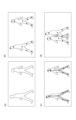
一般にバラ積み部品の自動ロボットピッキングにおいては、部品の姿勢を知ることが重要である。例えば、図10に示すようなネジ701をロボットアームで把持するためには、702と703などネジの適切な部分を把持する必要がある。702と704を把持した場合は、把持が不安定となり、把持したネジが落下する可能性がある。
Generally, in automatic robot picking of bulk parts, it is important to know the orientation of the parts. For example, in order to grip a
このように、部品をピッキングするためには、部品を把持しやすい点(以後、特徴点と呼ぶ)を調査することが重要となる。そこで、本実施形態においては、実施形態1で説明した関節位置推定を、部品の特徴点検出に応用する方法を説明する。本実施形態の構成図を図11に示す。本実施形態は、画像取得部801、推定部802、認識部803から構成される。
In this way, in order to pick parts, it is important to investigate points (hereinafter referred to as feature points) that make it easy to grip the part. Therefore, in this embodiment, a method will be described in which the joint position estimation described in Embodiment 1 is applied to feature point detection of parts. A configuration diagram of this embodiment is shown in FIG. This embodiment includes an
画像取得部801は、S801において、ピッキング対象となる部品が映った画像を取得する。推定部802は、実施形態1における図2の推定部102に対応する。推定部802はS802において、部品を把持すべき特徴点の位置と、検出された特徴点のスコアとを推定する。特徴点の検出方法は、実施形態1の関節位置推定方法と対応する。特徴点のスコアは、同一部品内の異なる特徴点同士を結ぶ線上に同一スコアが埋め込まれるように学習した学習済みモデルに取得した画像を入力することで得たスコアマップを用いて推定される。特徴点のスコアマップの推定方法の詳細は、実施形態1のスコアマップを推定する方法と同様である。S803において、認識部803は、推定部802によって得られたスコアに基づいて、当該特徴点が属する部品を認識する。実施形態1の認識部106に対応する。
In S801, the
<実施形態3>
本実施形態では、実施形態1において説明した、関節位置推定を、スポーツシーンの映像自動解析に応用する例を示す。なお、ハードウェア構成は、図1で示した実施形態1と同様の構成でよい。
<Embodiment 3>
In this embodiment, an example will be shown in which the joint position estimation described in Embodiment 1 is applied to automatic video analysis of a sports scene. Note that the hardware configuration may be the same as that of the first embodiment shown in FIG.
スポーツシーン、特にボールを使った、サッカーやラグビー、バスケットボールなどの球技の映像の自動解析においては、どの人物がボールを支配しているかが重要となる。各人物がボールを支配している時間や、ボールを支配している際の人物のスピード、ボールを支配している人物がシュートやパスを放つタイミングなどを解析する。これによって、どのようなタイミングでシュートやパスを放つのが効果的か、などの情報を知ることができる。 In automatic analysis of footage of sports scenes, especially ball games such as soccer, rugby, and basketball, it is important to know which person is in control of the ball. Analyzes the amount of time each person is in control of the ball, the speed of the person when they are in control, and the timing of shots and passes by the person in control of the ball. This allows you to learn information such as what timing is most effective for shooting or passing.
本実施形態においては、実施形態1で説明した関節位置推定を、ボールを支配する人物の推定に応用する方法を説明する。本実施形態の構成図を図13に示す。本実施形態は、画像取得部901、推定部902、認識部903から、構成される。
In this embodiment, a method will be described in which the joint position estimation described in Embodiment 1 is applied to estimation of the person controlling the ball. A configuration diagram of this embodiment is shown in FIG. This embodiment includes an
図14のフローチャートを用いて処理の流れを説明する。まず、S901において、画像取得部901は、解析対象となるスポーツシーン映像を取得する。例えば、図16に示すような、人物とボールがある程度近接した状態の画像を取得する。推定部902は、実施形態1における図2の推定部102に対応する。S902において、推定部902は、画像から人物とボールの位置と、人物とボールそれぞれのスコアとを推定する。人物とボールの位置の推定方法は、実施形態1の関節位置推定方法と同じであるため、説明を省略する。また、推定部902は、人物とボールを結ぶ線上に同一スコアを推定するように学習された推定器を用いてスコアを推定する。S903において、認識部904は、推定部902によって得られたスコアに基づいて、ボールを支配している人物を推定する。実施形態1の認識部106に対応する。ここでは、例えば、ボールと人物の足の関節との距離が最も小さい人物がボールを支配していると認識する。
The flow of processing will be explained using the flowchart of FIG. First, in S901, the
本発明は、以下の処理を実行することによっても実現される。即ち、上述した実施形態の機能を実現するソフトウェア(プログラム)を、データ通信用のネットワーク又は各種記憶媒体を介してシステム或いは装置に供給する。そして、そのシステム或いは装置のコンピュータ(またはCPUやMPU等)がプログラムを読み出して実行する処理である。また、そのプログラムをコンピュータが読み取り可能な記録媒体に記録して提供してもよい。 The present invention is also realized by performing the following processing. That is, software (programs) that implement the functions of the embodiments described above are supplied to the system or device via a data communication network or various storage media. This is a process in which the computer (or CPU, MPU, etc.) of the system or device reads and executes the program. Further, the program may be recorded on a computer-readable recording medium and provided.
1 情報処理装置
101 画像取得部
102 推定部
104 特定部
105 記憶部
106 認識部
1
Claims (14)
前記複数の物体のそれぞれの関節の位置に対して前記複数の物体の個体に応じたスコアを示すスコアマップを出力するように学習された学習済みモデルに前記画像を入力する入力手段と、
前記入力手段により前記学習済みモデルに前記画像が入力されることで得られるスコアであって前記関節の位置に対応するスコアに基づいて、前記位置情報により示される関節同士を結ぶ線がどの物体に属するかを特定する特定手段と、を有することを特徴とする情報処理装置。 acquisition means for acquiring position information indicating the position of each joint of a plurality of objects detected from the image ;
input means for inputting the image to a trained model that has been trained to output a score map indicating a score according to each individual of the plurality of objects for the position of each joint of the plurality of objects ;
Based on the score obtained by inputting the image to the trained model by the input means and corresponding to the position of the joint, determine which object the line connecting the joints indicated by the position information corresponds to. An information processing device characterized by having a specifying means for specifying whether the device belongs to the group .
前記特定手段は、前記スコアマップを参照することで前記関節の位置に対応するスコアを特定することを特徴とする請求項1に記載の情報処理装置。The information processing apparatus according to claim 1, wherein the specifying means specifies the score corresponding to the position of the joint by referring to the score map.
前記特定手段は、前記関節の種類に応じて決定された関節のペアを結ぶ2以上の線分のそれぞれのスコアに基づいて同一物体に属する関節のペアを判定することを特徴とする請求項1又は2に記載の情報処理装置。 The position information indicates the position of the joint for each type of joint,
3. The identifying means determines a pair of joints belonging to the same object based on scores of each of two or more line segments connecting the pair of joints determined according to the type of the joint. 2. The information processing device according to 1 or 2.
前記学習済みモデルは、前記位置情報に基づいて、同じ物体に属する関節の位置に対応づけられた前記スコアの分散が小さくなるように学習されることを特徴とする請求項1乃至4のいずれか1項に記載の情報処理装置。 The position information indicates the position of a joint belonging to the object for each type of joint in the image and the positional relationship between joints of different types,
5. The trained model is trained based on the position information so that the variance of the scores associated with positions of joints belonging to the same object is reduced. The information processing device according to any one of the items.
前記取得手段は、前記学習済みモデルに基づいて、関節毎の前記位置情報を取得することを特徴とする請求項1乃至9のいずれか1項に記載の情報処理装置。 further comprising a learning means for learning the trained model that has been trained to output the position information and the score map,
10. The information processing apparatus according to claim 1, wherein the acquisition means acquires the position information for each joint based on the learned model.
前記スコアマップに対する損失値を前記GTマップに基づいて算出し、前記損失値が所定の閾値より大きい場合に前記学習済みモデルのパラメータを更新することを特徴とする請求項10に記載の情報処理装置。 The learning means generates a GT map indicating joint positions for each type of joint based on joint data indicating positions of a plurality of joints belonging to the object,
The information processing apparatus according to claim 10 , wherein a loss value for the score map is calculated based on the GT map, and parameters of the learned model are updated when the loss value is larger than a predetermined threshold. .
前記複数の物体のそれぞれの関節の位置に対して前記複数の物体の個体に応じたスコアを示すスコアマップを出力するように学習された学習済みモデルに前記画像を入力する入力工程と、
前記入力工程により前記学習済みモデルに前記画像が入力されることで得られるスコアであって前記関節の位置に対応するスコアに基づいて、前記位置情報により示される関節同士を結ぶ線がどの物体に属するかを特定する特定工程と、を有することを特徴とする情報処理方法。 an acquisition step of acquiring position information indicating the position of each joint of a plurality of objects detected from the image ;
an input step of inputting the image to a trained model that has been trained to output a score map indicating a score according to the individual of the plurality of objects for the position of each joint of the plurality of objects ;
Based on the score obtained by inputting the image to the learned model in the input step and corresponding to the position of the joint, it is determined which object the line connecting the joints indicated by the position information corresponds to. An information processing method characterized by having a specifying step of specifying whether the information belongs .
Priority Applications (2)
| Application Number | Priority Date | Filing Date | Title |
|---|---|---|---|
| JP2019213738A JP7422456B2 (en) | 2019-11-26 | 2019-11-26 | Image processing device, image processing method and program |
| US17/095,413 US11836944B2 (en) | 2019-11-26 | 2020-11-11 | Information processing apparatus, information processing method, and storage medium |
Applications Claiming Priority (1)
| Application Number | Priority Date | Filing Date | Title |
|---|---|---|---|
| JP2019213738A JP7422456B2 (en) | 2019-11-26 | 2019-11-26 | Image processing device, image processing method and program |
Publications (3)
| Publication Number | Publication Date |
|---|---|
| JP2021086322A JP2021086322A (en) | 2021-06-03 |
| JP2021086322A5 JP2021086322A5 (en) | 2022-10-27 |
| JP7422456B2 true JP7422456B2 (en) | 2024-01-26 |
Family
ID=75974180
Family Applications (1)
| Application Number | Title | Priority Date | Filing Date |
|---|---|---|---|
| JP2019213738A Active JP7422456B2 (en) | 2019-11-26 | 2019-11-26 | Image processing device, image processing method and program |
Country Status (2)
| Country | Link |
|---|---|
| US (1) | US11836944B2 (en) |
| JP (1) | JP7422456B2 (en) |
Families Citing this family (4)
| Publication number | Priority date | Publication date | Assignee | Title |
|---|---|---|---|---|
| US11842509B2 (en) * | 2019-12-24 | 2023-12-12 | Canon Kabushiki Kaisha | Information processing apparatus, information processing method, and storage medium |
| JP2023149600A (en) * | 2022-03-31 | 2023-10-13 | 株式会社アイシン | Object feature point detection device |
| JP7455889B2 (en) | 2022-04-08 | 2024-03-26 | 楽天グループ株式会社 | Image evaluation device, image processing system, user terminal, image evaluation method, and image evaluation program |
| WO2023228304A1 (en) * | 2022-05-25 | 2023-11-30 | Nec Corporation | Key-point associating apparatus, key-point associating method, and non-transitory computer-readable storage medium |
Citations (2)
| Publication number | Priority date | Publication date | Assignee | Title |
|---|---|---|---|---|
| JP2018013999A (en) | 2016-07-21 | 2018-01-25 | 日本電信電話株式会社 | Pose estimation device, method, and program |
| JP2019185420A (en) | 2018-04-11 | 2019-10-24 | 株式会社アジラ | Action estimation device |
-
2019
- 2019-11-26 JP JP2019213738A patent/JP7422456B2/en active Active
-
2020
- 2020-11-11 US US17/095,413 patent/US11836944B2/en active Active
Patent Citations (2)
| Publication number | Priority date | Publication date | Assignee | Title |
|---|---|---|---|---|
| JP2018013999A (en) | 2016-07-21 | 2018-01-25 | 日本電信電話株式会社 | Pose estimation device, method, and program |
| JP2019185420A (en) | 2018-04-11 | 2019-10-24 | 株式会社アジラ | Action estimation device |
Non-Patent Citations (1)
| Title |
|---|
| NEWELL, Alejandro、他2名,Associative Embedding: End-to-End Learning for Joint Detection and Grouping,Computer Vision and Pattern Recognition,ARXIV.ORG,2017年06月09日,p.1-11,インターネット:<URL:https://arxiv.org/pdf/1611.05424.pdf> |
Also Published As
| Publication number | Publication date |
|---|---|
| US20210158566A1 (en) | 2021-05-27 |
| US11836944B2 (en) | 2023-12-05 |
| JP2021086322A (en) | 2021-06-03 |
Similar Documents
| Publication | Publication Date | Title |
|---|---|---|
| JP7422456B2 (en) | Image processing device, image processing method and program | |
| CN107545582B (en) | Video multi-target tracking method and device based on fuzzy logic | |
| US10242266B2 (en) | Method and system for detecting actions in videos | |
| US9330470B2 (en) | Method and system for modeling subjects from a depth map | |
| WO2020042419A1 (en) | Gait-based identity recognition method and apparatus, and electronic device | |
| US20200074165A1 (en) | Image analysis using neural networks for pose and action identification | |
| Lee et al. | Human pose tracking in monocular sequence using multilevel structured models | |
| Kim et al. | Simultaneous gesture segmentation and recognition based on forward spotting accumulative HMMs | |
| KR100886557B1 (en) | System and method for face recognition based on adaptive learning | |
| Del Rincón et al. | Tracking human position and lower body parts using Kalman and particle filters constrained by human biomechanics | |
| US20220254157A1 (en) | Video 2D Multi-Person Pose Estimation Using Multi-Frame Refinement and Optimization | |
| CN114067358A (en) | Human body posture recognition method and system based on key point detection technology | |
| CN112989889B (en) | Gait recognition method based on gesture guidance | |
| CN109255783B (en) | Method for detecting position arrangement of human skeleton key points on multi-person image | |
| Li et al. | Robust multiperson detection and tracking for mobile service and social robots | |
| CN106909890A (en) | A kind of Human bodys' response method based on position cluster feature | |
| CN109492588A (en) | A kind of rapid vehicle detection and classification method based on artificial intelligence | |
| CN111639602A (en) | Pedestrian shielding and orientation detection method | |
| Bhargavas et al. | Human identification using gait recognition | |
| Sheu et al. | Improvement of human pose estimation and processing with the intensive feature consistency network | |
| JP2005351814A (en) | Detector and detecting method | |
| Jessika et al. | A study on part affinity fields implementation for human pose estimation with deep neural network | |
| Botzheim et al. | Growing neural gas for information extraction in gesture recognition and reproduction of robot partners | |
| JP5688514B2 (en) | Gaze measurement system, method and program | |
| De Beugher et al. | Semi-automatic hand annotation making human-human interaction analysis fast and accurate |
Legal Events
| Date | Code | Title | Description |
|---|---|---|---|
| A521 | Request for written amendment filed |
Free format text: JAPANESE INTERMEDIATE CODE: A523 Effective date: 20221018 |
|
| A621 | Written request for application examination |
Free format text: JAPANESE INTERMEDIATE CODE: A621 Effective date: 20221018 |
|
| A977 | Report on retrieval |
Free format text: JAPANESE INTERMEDIATE CODE: A971007 Effective date: 20230810 |
|
| A131 | Notification of reasons for refusal |
Free format text: JAPANESE INTERMEDIATE CODE: A131 Effective date: 20230822 |
|
| A521 | Request for written amendment filed |
Free format text: JAPANESE INTERMEDIATE CODE: A523 Effective date: 20231018 |
|
| TRDD | Decision of grant or rejection written | ||
| A01 | Written decision to grant a patent or to grant a registration (utility model) |
Free format text: JAPANESE INTERMEDIATE CODE: A01 Effective date: 20231212 |
|
| RD01 | Notification of change of attorney |
Free format text: JAPANESE INTERMEDIATE CODE: A7421 Effective date: 20231213 |
|
| A61 | First payment of annual fees (during grant procedure) |
Free format text: JAPANESE INTERMEDIATE CODE: A61 Effective date: 20240110 |
|
| R151 | Written notification of patent or utility model registration |
Ref document number: 7422456 Country of ref document: JP Free format text: JAPANESE INTERMEDIATE CODE: R151 |