JP7406390B2 - Calibration device and its control method - Google Patents
Calibration device and its control method Download PDFInfo
- Publication number
- JP7406390B2 JP7406390B2 JP2020021878A JP2020021878A JP7406390B2 JP 7406390 B2 JP7406390 B2 JP 7406390B2 JP 2020021878 A JP2020021878 A JP 2020021878A JP 2020021878 A JP2020021878 A JP 2020021878A JP 7406390 B2 JP7406390 B2 JP 7406390B2
- Authority
- JP
- Japan
- Prior art keywords
- angular velocity
- inertial sensor
- value
- kurtosis
- values
- Prior art date
- Legal status (The legal status is an assumption and is not a legal conclusion. Google has not performed a legal analysis and makes no representation as to the accuracy of the status listed.)
- Active
Links
- 238000000034 method Methods 0.000 title claims description 20
- 230000001133 acceleration Effects 0.000 claims description 37
- 238000012937 correction Methods 0.000 claims description 30
- 239000002131 composite material Substances 0.000 claims description 24
- 238000009795 derivation Methods 0.000 claims description 7
- 238000004364 calculation method Methods 0.000 description 29
- 238000010586 diagram Methods 0.000 description 17
- 238000009499 grossing Methods 0.000 description 13
- 238000012545 processing Methods 0.000 description 9
- 238000005259 measurement Methods 0.000 description 5
- 230000001419 dependent effect Effects 0.000 description 2
- 230000006870 function Effects 0.000 description 2
- 230000035939 shock Effects 0.000 description 2
- 238000006243 chemical reaction Methods 0.000 description 1
- 238000009434 installation Methods 0.000 description 1
- 238000012986 modification Methods 0.000 description 1
- 230000004048 modification Effects 0.000 description 1
- 238000012544 monitoring process Methods 0.000 description 1
- 239000004065 semiconductor Substances 0.000 description 1
- 239000007787 solid Substances 0.000 description 1
- 230000002123 temporal effect Effects 0.000 description 1
Images


Classifications
-
- G—PHYSICS
- G01—MEASURING; TESTING
- G01P—MEASURING LINEAR OR ANGULAR SPEED, ACCELERATION, DECELERATION, OR SHOCK; INDICATING PRESENCE, ABSENCE, OR DIRECTION, OF MOVEMENT
- G01P21/00—Testing or calibrating of apparatus or devices covered by the preceding groups
-
- G—PHYSICS
- G01—MEASURING; TESTING
- G01C—MEASURING DISTANCES, LEVELS OR BEARINGS; SURVEYING; NAVIGATION; GYROSCOPIC INSTRUMENTS; PHOTOGRAMMETRY OR VIDEOGRAMMETRY
- G01C21/00—Navigation; Navigational instruments not provided for in groups G01C1/00 - G01C19/00
- G01C21/10—Navigation; Navigational instruments not provided for in groups G01C1/00 - G01C19/00 by using measurements of speed or acceleration
- G01C21/12—Navigation; Navigational instruments not provided for in groups G01C1/00 - G01C19/00 by using measurements of speed or acceleration executed aboard the object being navigated; Dead reckoning
- G01C21/16—Navigation; Navigational instruments not provided for in groups G01C1/00 - G01C19/00 by using measurements of speed or acceleration executed aboard the object being navigated; Dead reckoning by integrating acceleration or speed, i.e. inertial navigation
-
- G—PHYSICS
- G01—MEASURING; TESTING
- G01C—MEASURING DISTANCES, LEVELS OR BEARINGS; SURVEYING; NAVIGATION; GYROSCOPIC INSTRUMENTS; PHOTOGRAMMETRY OR VIDEOGRAMMETRY
- G01C25/00—Manufacturing, calibrating, cleaning, or repairing instruments or devices referred to in the other groups of this subclass
- G01C25/005—Manufacturing, calibrating, cleaning, or repairing instruments or devices referred to in the other groups of this subclass initial alignment, calibration or starting-up of inertial devices
-
- G—PHYSICS
- G01—MEASURING; TESTING
- G01P—MEASURING LINEAR OR ANGULAR SPEED, ACCELERATION, DECELERATION, OR SHOCK; INDICATING PRESENCE, ABSENCE, OR DIRECTION, OF MOVEMENT
- G01P13/00—Indicating or recording presence, absence, or direction, of movement
-
- G—PHYSICS
- G01—MEASURING; TESTING
- G01P—MEASURING LINEAR OR ANGULAR SPEED, ACCELERATION, DECELERATION, OR SHOCK; INDICATING PRESENCE, ABSENCE, OR DIRECTION, OF MOVEMENT
- G01P15/00—Measuring acceleration; Measuring deceleration; Measuring shock, i.e. sudden change of acceleration
- G01P15/02—Measuring acceleration; Measuring deceleration; Measuring shock, i.e. sudden change of acceleration by making use of inertia forces using solid seismic masses
Landscapes
- Physics & Mathematics (AREA)
- General Physics & Mathematics (AREA)
- Engineering & Computer Science (AREA)
- Radar, Positioning & Navigation (AREA)
- Remote Sensing (AREA)
- Automation & Control Theory (AREA)
- Manufacturing & Machinery (AREA)
- Gyroscopes (AREA)
Description
本発明は、慣性センサの較正に関するものである。 The present invention relates to the calibration of inertial sensors.
慣性センサ(IMU:Inertial Measurement Unit)は、運動体の挙動を計測・制御する用途に使用され、カメラ、ゲーム機器、車両などに搭載されている。また、近年では、仮想現実(VR:Virtual Reality)や複合現実(MR:Mixed Reality)を実現する電子機器に広範に採用されている。慣性センサは、角速度(Gyro)センサおよび加速度センサを含み、角速度および加速度を出力する。一般に、慣性センサから出力されるこれらの値には誤差が含まれることが知られている。 Inertial sensors (IMUs) are used to measure and control the behavior of moving objects, and are installed in cameras, game devices, vehicles, and the like. Furthermore, in recent years, it has been widely adopted in electronic devices that realize virtual reality (VR) and mixed reality (MR). The inertial sensor includes an angular velocity (Gyro) sensor and an acceleration sensor, and outputs angular velocity and acceleration. It is generally known that these values output from inertial sensors include errors.
誤差は、「ゲイン」と「バイアス」を使ってモデル化することが可能である。特許文献1には、3軸加速度センサの合成加速度が重力加速度とほぼ一致していることをもって静止を判定し、静止判定された期間中の角速度値を用いて、バイアス値を更新することが記載されている。また、非特許文献1には、加速度の3軸合成成分と重力加速度との差分、各軸の前回角速度値と現在の角速度値の差、バイアス値を差し引いた各軸の現在角速度値、のそれぞれが閾値以下である場合に静止していると判定することが記載されている。 Errors can be modeled using "gains" and "biases." Patent Document 1 describes that it is determined that the device is stationary based on the fact that the composite acceleration of the three-axis acceleration sensor almost matches the gravitational acceleration, and that the bias value is updated using the angular velocity value during the period when the device is determined to be stationary. has been done. Additionally, Non-Patent Document 1 describes the difference between the three-axis composite component of acceleration and the gravitational acceleration, the difference between the previous angular velocity value and the current angular velocity value of each axis, and the current angular velocity value of each axis after subtracting the bias value. It is described that the object is determined to be stationary when is less than or equal to a threshold value.
しかしながら、慣性センサにより得られる加速度ないし角速度は、温度変化・気圧変化・振動・衝撃などにも影響を受ける。そのため、補正精度にも影響を与え、場合によってはユーザにとって満足な精度を持つ補正結果が得られないことがある。 However, the acceleration or angular velocity obtained by an inertial sensor is also affected by temperature changes, pressure changes, vibrations, shocks, etc. Therefore, the correction accuracy is affected, and in some cases, it may not be possible to obtain a correction result with an accuracy that is satisfactory to the user.
本発明は、このような問題に鑑みてなされたものであり、慣性センサの較正をより好適に実現可能とする技術を提供することを目的としている。 The present invention has been made in view of such problems, and an object of the present invention is to provide a technique that makes it possible to calibrate an inertial sensor more suitably.
上述の問題点を解決するため、本発明に係る較正装置は以下の構成を備える。すなわち、慣性センサの較正装置は、
前記慣性センサから角速度値を取得する取得手段と、
所与の期間に前記取得手段が取得した複数の角速度値に関して、時間的に隣接する角速度値の差分の分布を導出する導出手段と、
前記分布に基づいて、該所与の期間に前記慣性センサが静止状態であったか否かを判定する判定手段と、
前記判定手段により前記慣性センサが静止状態にあると判定された場合に、前記複数の角速度値に基づいて前記慣性センサのバイアス値を決定し、前記取得手段により得られた角速度値を補正する補正手段と、
を有し、
前記取得手段は、前記慣性センサから3軸の角速度値を取得し、
前記導出手段は、前記所与の期間に前記取得手段が取得した複数の3軸の角速度値に関して、時間的に隣接する角速度値の差分を3軸それぞれについて計算し、該3軸の差分の合成成分を計算し、前記所与の期間における前記合成成分の分布の尖度を計算し、
前記判定手段は、前記尖度が閾値より大きい場合に前記慣性センサが静止状態であったと判定する。
In order to solve the above-mentioned problems, a calibration device according to the present invention has the following configuration. That is, the inertial sensor calibration device is
acquisition means for acquiring an angular velocity value from the inertial sensor;
Derivation means for deriving a distribution of differences between temporally adjacent angular velocity values with respect to a plurality of angular velocity values acquired by the acquisition means in a given period;
determination means for determining whether or not the inertial sensor was in a stationary state during the given period based on the distribution;
Correction of determining a bias value of the inertial sensor based on the plurality of angular velocity values and correcting the angular velocity value obtained by the acquiring means when the determining means determines that the inertial sensor is in a stationary state. means and
has
The acquisition means acquires angular velocity values of three axes from the inertial sensor,
The derivation means calculates the difference between temporally adjacent angular velocity values for each of the three axes, with respect to the angular velocity values of the plurality of three axes acquired by the acquisition means in the given period, and synthesizes the differences of the three axes. calculating the kurtosis of the distribution of the composite component in the given period;
The determining means determines that the inertial sensor is in a stationary state when the kurtosis is larger than a threshold value .
本発明によれば、慣性センサの較正をより好適に実現可能とする技術を提供することができる。 According to the present invention, it is possible to provide a technique that enables more suitable calibration of an inertial sensor.
以下、添付図面を参照して実施形態を詳しく説明する。なお、以下の実施形態は特許請求の範囲に係る発明を限定するものではない。実施形態には複数の特徴が記載されているが、これらの複数の特徴の全てが発明に必須のものとは限らず、また、複数の特徴は任意に組み合わせられてもよい。さらに、添付図面においては、同一若しくは同様の構成に同一の参照番号を付し、重複した説明は省略する。 Hereinafter, embodiments will be described in detail with reference to the accompanying drawings. Note that the following embodiments do not limit the claimed invention. Although a plurality of features are described in the embodiments, not all of these features are essential to the invention, and the plurality of features may be arbitrarily combined. Furthermore, in the accompanying drawings, the same or similar components are designated by the same reference numerals, and redundant description will be omitted.
(第1実施形態)
本発明に係る較正装置の第1実施形態として、慣性センサのバイアス補正を行う較正装置を例に挙げて以下に説明する。
(First embodiment)
As a first embodiment of the calibration device according to the present invention, a calibration device that performs bias correction of an inertial sensor will be described below as an example.
<慣性センサの較正>
慣性センサからの出力値に含まれる誤差は、「ゲイン(g)」と「バイアス(b)」を用いて数式(1)のようにモデル化することが可能である。ここで、ωは取得された角速度値、ω’は補正後の角速度値である。
<Inertial sensor calibration>
The error included in the output value from the inertial sensor can be modeled using "gain (g)" and "bias (b)" as shown in equation (1). Here, ω is the acquired angular velocity value, and ω' is the corrected angular velocity value.
![]()
![]()
ゲインによる誤差は、センサが実際の運動量とは異なる量(異なるスケール)を出力することに起因する。例えば、慣性センサから角速度値「60」が計測されたとする。しかし実際には慣性センサは角速度値「30」で運動していたとする。その場合、角速度のゲイン値は「2」となる。バイアスによる誤差は、角速度センサが出力する角速度値が一定のオフセットを持って出力することに起因する。例えば、静止状態にあるにも関わらず慣性センサが「0」から離れた角速度値を測定により得る場合、当該慣性センサはバイアス値を加算した角速度値を出力することになる。 The error due to the gain is caused by the sensor outputting a different amount (different scale) from the actual amount of momentum. For example, assume that an angular velocity value of "60" is measured by the inertial sensor. However, it is assumed that the inertial sensor is actually moving at an angular velocity value of "30". In that case, the gain value of the angular velocity is "2". The bias-induced error is caused by the angular velocity value output by the angular velocity sensor having a certain offset. For example, if an inertial sensor obtains an angular velocity value far from "0" by measurement despite being in a stationary state, the inertial sensor will output an angular velocity value to which a bias value has been added.
そこで、測定により得られた角速度値からバイアス値を減算することで実際の運動に即した角速度値を得るバイアス補正が利用されている。バイアス補正は、オフセット補正、ゼロレート補正、zero-motion calculationとも呼ばれる。特に、静止時に得られる角速度値は、バイアス値と同等であると考えられるため、一定時間慣性センサを静止させ、その時間の角速度を測定しその平均をバイアス値とすることが広く行われている。 Therefore, bias correction is used to subtract a bias value from the angular velocity value obtained through measurement to obtain an angular velocity value that corresponds to the actual movement. Bias correction is also called offset correction, zero rate correction, or zero-motion calculation. In particular, since the angular velocity value obtained when stationary is considered to be equivalent to the bias value, it is widely practiced to keep the inertial sensor stationary for a certain period of time, measure the angular velocity during that time, and use the average as the bias value. .
一般にバイアス値とゲイン値を用いた角速度値の較正は、数式(1)に従って行われる。なお、複数の軸(例えば3軸)に関して角速度が出力されている場合には、それぞれの軸に対してゲイン値、バイアス値を計算する。 Generally, calibration of an angular velocity value using a bias value and a gain value is performed according to equation (1). Note that when angular velocities are output with respect to a plurality of axes (for example, three axes), a gain value and a bias value are calculated for each axis.
バイアス補正は、慣性センサの使用を開始する度、またはユーザが姿勢値にずれを感じる度に、ユーザによって実施されることが多い。これは、温度、気圧、外部震動・衝撃などによって慣性センサの出力特性が変わりバイアス値が変化するためである。しかしながら、バイアス補正のための操作やバイアス補正の必要性判断を行うことがユーザにとって煩わしいという問題がある。そのため、ユーザが意識することなく自動的にバイアス補正が行われるようにすることが望まれている。 Bias correction is often performed by the user each time he or she starts using the inertial sensor or whenever the user senses a shift in attitude values. This is because the output characteristics of the inertial sensor change depending on temperature, atmospheric pressure, external vibration/shock, etc., and the bias value changes. However, there is a problem in that it is troublesome for the user to perform operations for bias correction and to determine the necessity of bias correction. Therefore, it is desired that bias correction be performed automatically without the user being aware of it.
そこで、以下では、慣性センサの出力値を監視することにより好適に当該慣性センサが静止状態にあることを検出しバイアス補正を行う慣性センサについて説明する。 Therefore, an inertial sensor that preferably detects that the inertial sensor is in a stationary state and performs bias correction by monitoring the output value of the inertial sensor will be described below.
<装置構成>
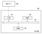
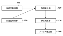
図1は、第1実施形態に係る較正装置100の機能構成を示すブロック図である。較正装置100は、角速度取得部110と、指標算出部120と、静止判定部130と、バイアス補正部140を有する。図2は、較正装置100のハードウェア構成を示すブロック図である。較正装置100は、入力部101、記憶部102、制御部103、およびバス104を備える。図示されるように、角速度取得部110は、角速度を検出/計測する慣性センサ200に相当する。また、指標算出部120と静止判定部130とバイアス補正部140は、較正装置100に相当する。較正装置100は、慣性センサ200からの出力(角速度値)を受信し較正の処理を行う装置である。なお、図2では、較正装置100と慣性センサ200とを別体のものとして記載しているが、一体の構成(例えば頭部搭載型ディスプレイ)としてもよい。
<Device configuration>
FIG. 1 is a block diagram showing the functional configuration of a
角速度取得部110は、慣性センサ200から出力される角速度値を受信し取得する。慣性センサ200は、測定対象の物体(例えば、頭部搭載型ディスプレイ)に設置され、当該設置場所における角速度を周期的(たとえば5ms毎)に計測し出力する。以下の説明では、慣性センサ200は3軸(XYZ)の角速度(yaw,pitch,roll)を計測可能に構成されることを想定するが、1軸以上の角速度値を出力可能であればよい。慣性センサ200からの出力値は、角速度を符号化(デジタル数値化)したものである。以下では、説明を簡単にするために、慣性センサ200からの出力値は「deg/s」の単位で表される角速度値であるとする。なお、角速度取得部110は、取得した角速度値を即時指標算出部120に与えても良いし、一時的にバッファ(不図示)に溜めてから与えても良い。
The angular
指標算出部120は、角速度取得部110から継続的に角速度値を受け取り、複数の角速度値に基づいて指標値を導出する。ここで、指標値は、所定の時間窓において、時間的に隣接する角速度値の差分(Δ角速度値)のヒストグラム分布の特徴を示す値である。詳細については図5および図6を参照して後述する。
The
静止判定部130は、指標算出部120により算出された指標値を利用して慣性センサ200が設置されている箇所が静止状態にある(慣性系に対して静止している)か否かの判定を行う。具体的には、静止判定部130は、指標算出部120から得た指標値が所定の条件を満たすか否かに基づいて静止状態にあるか否かの判定を行い、判定結果を出力する。
The
バイアス補正部140は、慣性センサ200から出力される角速度値に含まれるバイアス値を取り除く処理を行う。まず、バイアス補正部140は、静止判定部130によって静止状態と判定された期間の角速度値の平均値、または中央値、またはその他の統計的な代表値をバイアス値として決定する。そして、バイアス補正部140は、決定されたバイアス値を角速度値から取り除いた値を出力する。
The
入力部101は、慣性センサ200からの出力値(角速度値、加速度値)を較正装置100に入力する機能部である。入力部101は、併せて、較正装置100へ情報を入力するために使用される入力デバイスからの信号を較正装置100に入力してもよい。入力デバイスは、例えば、ユーザによるタッチを検出するタッチセンサ、マウス若しくはタッチパッドなどのポインティングデバイスを含み得る。さらに、入力デバイスは、キーボード、キーパッド、ボタン又はスイッチなどのその他の種類のデバイスを含み得る。
The
記憶部102は、半導体メモリ(RAMやROM)、ハードディスクドライブ(HDD)、ソリッドステートドライブ(SSD)などにより構成され、較正装置100による処理のためのプログラム及びデータを記憶する。記憶部102により記憶されるデータは、例えば、入力部101から得た角速度値、制御部103で計算した指標値、及び後述する様々なデータを含み得る。なお、本明細書で説明するプログラム及びデータの一部は、記憶部102の代わりに、外部のデータソース(例えば、データサーバ、ネットワークストレージ又は外付けメモリなど)から取得され得る。
The
制御部103は、CPU(Central Processing Unit)又はDSP(Digital Signal Processor)などのプロセッサにより構成される。制御部103は、記憶部102又は他の記憶媒体に記憶されるプログラムを実行することにより、後述する較正装置100の様々な処理を実現する。
The
バス104は、入力部101、記憶部102、制御部103を相互に通信可能に接続する。バス104は、有線接続によるものに限定されず、無線接続によるものであってもよい。
The
<装置の動作>
図3は、第1実施形態における較正装置100の動作を示すフローチャートである。特に、第1実施形態では、3軸(XYZ)のΔ角速度値の合成である合成成分(Δωa)の分布の尖度に基づき静止状態を判定する形態について説明する。なお、尖度そのものの代わりに、分布の尖り具合を示す他の指標(尖度を単純化したものなど)を用いてもよい。
<Device operation>
FIG. 3 is a flowchart showing the operation of the
ステップS101では、角速度取得部110(慣性センサ200)は、3軸の角速度を計測し、計測により得られた3軸の角速度値を時刻情報とともに指標算出部120に出力する。例えば、角速度値の更新間隔を200Hzに設定した場合、これらの角速度値は5msごとに出力される。以下のS101~S105のループは、角速度値が出力されるごと(すなわち5ms)に実行される。
In step S101, the angular velocity acquisition unit 110 (inertial sensor 200) measures the angular velocity of three axes, and outputs the angular velocity values of the three axes obtained by measurement to the
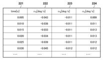
図4は、角速度取得部110により得られる角速度情報の例を示す図である。ここでは、角速度情報が、タイムスタンプ221、X軸周りの角速度(ωx)222、Y軸周りの角速度(ωy)223、Z軸周りの角速度(ωz)224を含む例を示している。ここでは角速度222~224の値は「deg/s」の単位で表されるものとしているが、センサ依存の値を出力するよう構成してもよい。加速度センサ依存の値は、角速度センサのデータシートなどに記載された換算式により所定の物理量(例えば「deg/s」)に変換され得る。また、ここでは5msごとに加速度情報が出力/追加されている例を示しているが、出力間隔は用途/アプリケーションの都合によって自由に設定され得る。
FIG. 4 is a diagram showing an example of angular velocity information obtained by the angular
ステップS102では、指標算出部120は、S101で取得された角速度情報から、各軸に関して角速度の差分(Δωx、Δωy、Δωz)を計算する。そして、さらに3軸の差分の合成成分Δωaを計算する。
In step S102, the
ステップS103では、指標算出部120は、S102で算出された合成成分Δωaに関して、所与の期間である時間窓(Δt)における分布を導出しの尖度を計算する。ここでは、現時刻(角速度情報の最新の時刻)から過去1秒間のデータに基づいて尖度を計算する。
In step S103, the
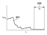
図5は、角速度差分の合成成分の時系列変化および時間窓の例を示す図である。横軸は時間を示し、縦軸は角速度の合成成分の大きさを示している。曲線231は、S102で算出された合成成分Δωaの時間変化を表している。時間窓232は、曲線231に対する時間窓を表しており、ここでは、現時刻(曲線231の右端)から過去1秒間の幅(Δt)の時間区間を表している。指標算出部120は、時間窓232に含まれる複数の合成成分Δωaの大きさのヒストグラム分布に基づいて、指標値である尖度を算出する。
FIG. 5 is a diagram showing an example of a time-series change in the composite component of the angular velocity difference and a time window. The horizontal axis shows time, and the vertical axis shows the magnitude of the composite component of angular velocity. A
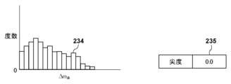
図6は、時間窓における合成成分の度数分布および尖度の例を示す図である。図5の時間窓232の期間におけるΔωaの度数分布がヒストグラム分布234として示されている。また、ヒストグラム分布234に基づいて算出された尖度の値がテーブル235に示されている。
FIG. 6 is a diagram showing an example of the frequency distribution and kurtosis of composite components in a time window. The frequency distribution of Δω a during the
指標算出部120は、数式(2)に示す計算によって合成成分Δωaの尖度を計算する。
The

ここで、
n:ヒストグラムを作るために用いられたΔωaの個数、
xi:ヒストグラムにおけるi番目の区間の出現回数(度数)、
x ̄:xiの平均、
s:時間窓232に含まれるΔωaの標準偏差、
である。
here,
n: number of Δω a used to create the histogram,
x i : number of occurrences (frequency) of the i-th interval in the histogram,
x  ̄ : average of x i ,
s: standard deviation of Δω a included in the
It is.
算出された尖度の値は、バッファに格納される。ここでは直近で求めた5回分の尖度の値をバッファすることを想定する。 The calculated kurtosis value is stored in a buffer. Here, it is assumed that the five most recently calculated kurtosis values are buffered.
ステップS104では、指標算出部120は、S103により算出された尖度を平滑化する。ここでは、直近で求めた5回分の尖度の値の平均を算出する。
In step S104, the
図10は、平滑化処理に用いられる尖度のリストを示す図である。このリストに格納された尖度の値は前述のバッファに格納された直近で求めた5回分の尖度の値に相当する。図10に示した5個の尖度の値の例に対しては、指標算出部120は、これら5個の平均である「0.0」を算出する。
FIG. 10 is a diagram showing a list of kurtosis values used in the smoothing process. The kurtosis values stored in this list correspond to the 5 most recently calculated kurtosis values stored in the buffer described above. For the example of five kurtosis values shown in FIG. 10, the
ステップS105では、静止判定部130は、S104で算出された平滑化指標値(尖度)を利用して静止状態であるか否かの判定を行う。ここでは、所定の条件として閾値「-0.5」より大きいという条件を満たす場合に静止状態であると判定する。すなわち、S104で算出された平滑化指標値が閾値より大きい場合に「真(=静止状態である)」と判定しS106に進み、閾値以下である場合に「偽」と判定しS101に戻る。そのため、平滑化指標値が「0.0」と算出されている場合は真と判定されS106に進む。なお、閾値は、例えば判定に求められる精度に応じて適宜設定され得る。
In step S105, the stationary
ステップS106では、バイアス補正部140は、S101で取得された角速度のバイアス補正を行う。ここでは、バイアス補正部140は、静止判定が真と判定された際の角速度情報を平均した値を、バイアス値として決定する。その後、バイアス補正部140は、S101で取得された角速度値からバイアス値を減算することで較正された角速度値を算出し、不図示のアプリケーションまたはプラットフォームに出力する。
In step S106, the
以上説明したとおり第1実施形態によれば、慣性センサ200により得られる角速度値に基づいてバイアス値を適応的/自動的に決定することが出来、慣性センサ200の較正をより好適に実現することが出来る。特に、角速度値の差分の合成成分Δωaに関する分布の尖度を指標値として用いることで、好適に静止状態であるか否かの判定を行うことが可能となる。
As explained above, according to the first embodiment, the bias value can be adaptively/automatically determined based on the angular velocity value obtained by the
(第2実施形態)
第2実施形態では、慣性センサの各回転軸における角速度差分の度数分布の歪度に基づいて静止状態を判定し、当該慣性センサのバイアス補正を行う形態について説明する。なお、装置構成については第1実施形態と同様であるため説明は省略する。
(Second embodiment)
In the second embodiment, a mode will be described in which the stationary state is determined based on the skewness of the frequency distribution of the angular velocity difference at each rotation axis of the inertial sensor, and the bias correction of the inertial sensor is performed. Note that the device configuration is the same as that in the first embodiment, so a description thereof will be omitted.
<装置の動作>
図7は、第2実施形態における較正装置の動作を示すフローチャートである。上述したように、第2実施形態では、3軸(XYZ)のΔ角速度値の分布の歪度に基づき静止状態を判定する形態について説明する。なお、歪度そのものの代わりに、分布の非対称性具合を示す他の指標(歪度を単純化したものなど)を用いてもよい。
<Device operation>
FIG. 7 is a flowchart showing the operation of the calibration device in the second embodiment. As described above, in the second embodiment, a mode will be described in which the stationary state is determined based on the skewness of the distribution of Δ angular velocity values of three axes (XYZ). Note that instead of the skewness itself, another index (such as a simplified version of the skewness) indicating the degree of asymmetry of the distribution may be used.
ステップS111では、角速度取得部110(慣性センサ200)は、3軸の角速度を計測し、計測により得られた3軸の角速度値を時刻情報とともに指標算出部120に出力する。例えば、角速度値の更新間隔を200Hzに設定した場合、これらの角速度値は5msごとに出力される。以下のS111~S115のループは、角速度値が出力されるごと(すなわち5ms)に実行される。
In step S111, the angular velocity acquisition unit 110 (inertial sensor 200) measures the angular velocity of the three axes, and outputs the angular velocity values of the three axes obtained by the measurement to the
ステップS112では、指標算出部120は、S111で取得された角速度情報から、各軸に関して角速度の差分(Δωi)を計算する。ここで、iは、x、y、zの各軸に対応する。
In step S112, the
ステップS113では、指標算出部120は、S112で算出された角速度の差分(Δωi)に関して、所与の期間である時間窓(Δt)における分布を導出し歪度を計算する。すなわち、3軸の各軸について歪度を計算する。ここでは、現時刻(角速度情報の最新の時刻)から過去1秒間のデータに基づいて尖度を計算する。
In step S113, the
図8は、角速度差分の時系列変化および時間窓の例を示す図である。横軸は時間を示し、縦軸は角速度の差分の大きさを示している。ここでは例としてX軸のみに関する時系列変化が示しているが、Y軸およびZ軸に関しても同様に算出される。 FIG. 8 is a diagram showing an example of a time-series change in angular velocity difference and a time window. The horizontal axis shows time, and the vertical axis shows the magnitude of the difference in angular velocity. Here, as an example, time-series changes only regarding the X-axis are shown, but calculations are similarly made regarding the Y-axis and the Z-axis.
曲線241は、S112で算出された角速度の差分(Δωi)の時間変化を表している。時間窓242は、曲線241に対する時間窓を表しており、ここでは、現時刻(曲線241の右端)から過去1秒間の幅(Δt)の時間区間を表している。指標算出部120は、時間窓242に含まれる複数の差分(Δωi)の大きさのヒストグラム分布に基づいて、指標値である歪度を算出する。
A
図9は、時間窓における角速度差分の度数分布および歪度の例を示す図である。図8の時間窓242の期間におけるΔωiの度数分布がヒストグラム分布244として示されている。また、ヒストグラム分布244に基づいて算出された歪度の値がテーブル245に示されている。ここでは例としてX軸のみに関する度数分布および歪度を示しているが、Y軸およびZ軸に関しても同様に算出される。
FIG. 9 is a diagram showing an example of the frequency distribution and skewness of the angular velocity difference in the time window. The frequency distribution of Δω i during the
指標算出部120は、数式(3)に示す計算によって角速度の差分(Δωi)の歪度を計算する。
The

ここで、
n:ヒストグラムを作るために用いられたΔωiの個数、
xi:ヒストグラムにおけるi番目の区間の出現回数(度数)、
x ̄:xiの平均、
s:時間窓242に含まれるΔωiの標準偏差、
である。
here,
n: number of Δω i used to create the histogram,
x i : number of occurrences (frequency) of the i-th interval in the histogram,
x  ̄ : average of x i ,
s: standard deviation of Δω i included in the
It is.
算出された歪度の値は、各軸についてバッファに格納される。ここでは直近で求めた5回分の歪度の値をバッファすることを想定する。 The calculated skewness values are stored in a buffer for each axis. Here, it is assumed that the five most recently calculated skewness values are buffered.
ステップS114では、指標算出部120は、S113により算出された各軸の歪度を平滑化する。ここでは、直近で求めた5回分の歪度の値の平均を算出する。
In step S114, the
図11は、平滑化処理に用いられる歪度のリストを示す図である。このリストに格納された歪度の値は前述のバッファに格納された直近で求めたX軸の5回分の歪度の値に相当する。図11に示した5個の歪度の値の例に対しては、指標算出部120は、これら5個の平均である「+0.3」を算出する。
FIG. 11 is a diagram showing a list of skewness levels used in the smoothing process. The skewness values stored in this list correspond to the 5 most recently calculated skewness values on the X-axis stored in the buffer described above. For the example of five skewness values shown in FIG. 11, the
ステップS115では、静止判定部130は、S114で算出された3軸の平滑化指標値(歪度)を利用して静止状態であるか否かの判定を行う。ここでは、所定の条件として、指標値の全てが閾値範囲「-0.5」から「+0.5」に含まれるという条件を満たす場合に静止状態であると判定する。すなわち、S114で算出された3軸の平滑化指標値全てが閾値範囲内にある場合に「真(=静止状態である)」と判定しS116に進む。一方、1軸でも閾値範囲外である場合には「偽」と判定しS111に戻る。そのため、X軸に関して平滑化指標値が「+0.3」と算出され、かつY軸・Z軸に関しても閾値範囲内である場合は真と判定されS116に進む。なお、閾値範囲は、例えば判定に求められる精度に応じて適宜設定され得る。
In step S115, the stationary
ステップS116では、バイアス補正部140は、S111で取得された角速度のバイアス補正を行う。ここでは、バイアス補正部140は、静止判定が真と判定された際の角速度情報を平均した値を、バイアス値として決定する。その後、バイアス補正部140は、S111で取得された角速度値からバイアス値を減算することで較正された角速度値を算出し、不図示のアプリケーションまたはプラットフォームに出力する。
In step S116, the
以上説明したとおり第2実施形態によれば、慣性センサ200により得られる角速度値に基づいてバイアス値を適応的/自動的に決定することが出来、慣性センサ200の較正をより好適に実現することが出来る。特に、各軸の角速度値の差分に関する分布の歪度を指標値として用いることで、好適に静止状態であるか否かの判定を行うことが可能となる。
As explained above, according to the second embodiment, the bias value can be determined adaptively/automatically based on the angular velocity value obtained by the
(第3実施形態)
第3実施形態では、慣性センサ200に含まれる加速度センサから出力をさらに利用する形態について説明する。具体的には、角速度による閾値判定に加え加速度による閾値判定を併用することにより、よりロバストな静止状態の判定を行っている。
(Third embodiment)
In the third embodiment, a mode will be described in which the output from the acceleration sensor included in the
<装置構成>
図12は、第3実施形態に係る較正装置の機能構成を示すブロック図である。第1実施形態の機能構成(図1)に対して加速度取得部150が追加されている。他の構成要素は第1実施形態と同様であるため説明を省略する。
<Device configuration>
FIG. 12 is a block diagram showing the functional configuration of a calibration device according to the third embodiment. An acceleration acquisition unit 150 is added to the functional configuration of the first embodiment (FIG. 1). The other components are the same as those in the first embodiment, and therefore their description will be omitted.
加速度取得部150は、慣性センサ200から出力される加速度値を受信し取得する。慣性センサ200は、角速度を定期的に計測し出力すると共に加速度を定期的に計測し出力する。以下の説明では、慣性センサ200は、角速度に加え3軸(XYZ)の加速度を計測可能に構成されることを想定する。慣性センサ200からの出力値は、加速度を符号化(デジタル数値化)したものである。以下では、説明を簡単にするために、慣性センサ200からの出力値は「m/s2」の単位で表される加速度値であるとする。なお、加速度取得部150は、取得した加速度値を即時指標算出部120に与えても良いし、一時的にバッファ(不図示)に溜めてから与えても良い。
Acceleration acquisition section 150 receives and acquires the acceleration value output from
<装置の動作>
図13は、第3実施形態における較正装置の動作を示すフローチャートである。S102、S103、S106については第1実施形態と同様であるため説明を省略する。なお、以下では、角速度と同様に、加速度に関しても差分の合成成分ΔAaの尖度を算出しているが、尖度そのものの代わりに、分布の尖り具合を示す他の指標(尖度を単純化したものなど)を用いてもよい。
<Device operation>
FIG. 13 is a flowchart showing the operation of the calibration device in the third embodiment. Since S102, S103, and S106 are the same as those in the first embodiment, their explanations will be omitted. In addition, in the following, the kurtosis of the composite component ΔA a of the difference is calculated for the acceleration as well as for the angular velocity, but instead of the kurtosis itself, another index indicating the sharpness of the distribution (kurtosis is simply calculated) ) may also be used.
ステップS201では、角速度取得部110(慣性センサ200)は、3軸の角速度を計測し、計測により得られた3軸の角速度値および3軸の加速度値を時刻情報とともに指標算出部120に出力する。例えば、角速度値および加速度値の更新間隔を200Hzに設定した場合、これらの値は5msごとに出力される。以下のS201~S205のループは、角速度値および加速度値が出力されるごと(すなわち5ms)に実行される。
In step S201, the angular velocity acquisition unit 110 (inertial sensor 200) measures the angular velocity of three axes, and outputs the angular velocity values of the three axes and acceleration values of the three axes obtained by the measurement to the
ステップS202では、指標算出部120は、S201で取得された加速度情報から、各軸に関して加速度の差分(ΔAx、ΔAy、ΔAz)を計算する。そして、さらに3軸の差分の合成成分ΔAaを計算する。
In step S202, the
ステップS203では、指標算出部120は、S202で算出された合成成分ΔAaに関して、所与の期間である時間窓(Δt)における分布の尖度を計算する。ここでは、現時点(角速度情報の最新の時刻)から過去1秒間のデータに基づいて尖度を計算する。
In step S203, the
ステップS204では、指標算出部120は、S103により算出された尖度およびS203により算出された尖度をそれぞれ平滑化する。ここでは、角速度および加速度それぞれに関して、直近で求めた5回分の尖度の値の平均を算出する。
In step S204, the
ステップS205では、静止判定部130は、S204で算出された角速度および加速度それぞれに関する平滑化指標値(尖度)を利用して静止状態であるか否かの判定を行う。第1実施形態のS105と同様に、S204で算出された平滑化指標値が閾値より大きい場合に「真(=静止状態である)」と判定し、閾値以下である場合に「偽」と判定する。角速度および加速度それぞれに関する平滑化指標値において、両方とも真と判定された場合にS106に進む。一方でも偽と判定されればS201に戻る。
In step S205, the stationary
以上説明したとおり第3実施形態によれば、慣性センサ200により得られる角速度値および加速度値に基づいてバイアス値を適応的/自動的に決定することが出来、慣性センサ200の較正をより好適に実現することが出来る。特に、第1実施形態に比較して、角速度・加速度という性質の異なる2つの測定値を利用することにより、よりロバストに静止状態の判定を行うことが可能となる。
As explained above, according to the third embodiment, the bias value can be adaptively/automatically determined based on the angular velocity value and the acceleration value obtained by the
(変形例)
慣性センサ200を固定設置する対象は、用途に応じて多岐に渡る。例えば、カメラ、ゲームのコントローラ、車両内部、仮想現実や複合現実を実現する頭部搭載型ディスプレイ(HMD:Head Mounted Display)などがある。例えばHMDに慣性センサ200を固定設置し、当該HMDを装着するユーザの頭部の位置姿勢を慣性センサ200によって計測しつつ、逐次上述の実施形態で説明した処理を実行し、慣性センサ200の較正を実現してもよい。
(Modified example)
The objects to which the
さらに、指標値の算出方法は、上述の実施形態で説明した算出方法に限定されるものではなく、較正装置100の外部から得られる他の情報と合わせて指標値を算出しても良い。例えば、HMDが、角速度取得部110とは別に画像処理・別個のセンサ利用などによって姿勢の計測を行っている場合には、当該計測された姿勢を利用して指標値を算出してもよい。具体的には、計測された姿勢の情報から上述の実施形態で説明したものと同様の処理により指標値を算出し、角速度取得部110から得られる指標値と合算して静止状態の判定を行うことが出来る。
Furthermore, the method of calculating the index value is not limited to the calculation method described in the above embodiment, and the index value may be calculated in conjunction with other information obtained from outside the
(その他の実施例)
本発明は、上述の実施形態の1以上の機能を実現するプログラムを、ネットワーク又は記憶媒体を介してシステム又は装置に供給し、そのシステム又は装置のコンピュータにおける1つ以上のプロセッサーがプログラムを読出し実行する処理でも実現可能である。また、1以上の機能を実現する回路(例えば、ASIC)によっても実現可能である。
(Other examples)
The present invention provides a system or device with a program that implements one or more of the functions of the embodiments described above via a network or a storage medium, and one or more processors in the computer of the system or device reads and executes the program. This can also be achieved by processing. It can also be realized by a circuit (for example, ASIC) that realizes one or more functions.
発明は上記実施形態に制限されるものではなく、発明の精神及び範囲から離脱することなく、様々な変更及び変形が可能である。従って、発明の範囲を公にするために請求項を添付する。 The invention is not limited to the embodiments described above, and various changes and modifications can be made without departing from the spirit and scope of the invention. Therefore, the following claims are hereby appended to disclose the scope of the invention.
100 較正装置; 110 角速度取得部; 120 指標算出部; 130 静止判定部; 140 バイアス補正部; 150 加速度取得部 100 Calibration device; 110 Angular velocity acquisition unit; 120 Index calculation unit; 130 Stationary determination unit; 140 Bias correction unit; 150 Acceleration acquisition unit
Claims (7)
前記慣性センサから角速度値を取得する取得手段と、
所与の期間に前記取得手段が取得した複数の角速度値に関して、時間的に隣接する角速度値の差分の分布を導出する導出手段と、
前記分布に基づいて、該所与の期間に前記慣性センサが静止状態であったか否かを判定する判定手段と、
前記判定手段により前記慣性センサが静止状態にあると判定された場合に、前記複数の角速度値に基づいて前記慣性センサのバイアス値を決定し、前記取得手段により得られた角速度値を補正する補正手段と、
を有し、
前記取得手段は、前記慣性センサから3軸の角速度値を取得し、
前記導出手段は、前記所与の期間に前記取得手段が取得した複数の3軸の角速度値に関して、時間的に隣接する角速度値の差分を3軸それぞれについて計算し、該3軸の差分の合成成分を計算し、前記所与の期間における前記合成成分の分布の尖度を計算し、
前記判定手段は、前記尖度が閾値より大きい場合に前記慣性センサが静止状態であったと判定する
ことを特徴とする較正装置。 A calibration device for an inertial sensor,
acquisition means for acquiring an angular velocity value from the inertial sensor;
Derivation means for deriving a distribution of differences between temporally adjacent angular velocity values with respect to a plurality of angular velocity values acquired by the acquisition means in a given period;
determination means for determining whether or not the inertial sensor was in a stationary state during the given period based on the distribution;
Correction of determining a bias value of the inertial sensor based on the plurality of angular velocity values and correcting the angular velocity value obtained by the acquiring means when the determining means determines that the inertial sensor is in a stationary state. means and
has
The acquisition means acquires angular velocity values of three axes from the inertial sensor,
The derivation means calculates the difference between temporally adjacent angular velocity values for each of the three axes, with respect to the angular velocity values of the plurality of three axes acquired by the acquisition means in the given period, and synthesizes the differences of the three axes. calculating the kurtosis of the distribution of the composite component in the given period;
The determining means determines that the inertial sensor is in a stationary state when the kurtosis is larger than a threshold value.
A calibration device characterized by:
前記所与の期間は、現時刻から直近の所定の時間に対応する期間である
ことを特徴とする請求項1に記載の較正装置。 The acquisition means is configured to acquire the angular velocity value at a predetermined period,
The calibration device according to claim 1 , wherein the given period is a period corresponding to a predetermined time most recent from the current time.
前記所与の期間に前記第2の取得手段が取得した複数の3軸の加速度値に関して、時間的に隣接する加速度値の差分を3軸それぞれについて計算し、該3軸の差分の第2の合成成分を計算し、前記所与の期間における前記第2の合成成分の分布の第2の尖度を計算する第2の導出手段と、
をさらに有し、
前記判定手段は、前記尖度が閾値より大きくかつ前記第2の尖度が第2の閾値より大きい場合に前記慣性センサが静止状態であったと判定する
ことを特徴とする請求項1に記載の較正装置。 a second acquisition means for acquiring three-axis acceleration values from the inertial sensor;
Regarding the plurality of three-axis acceleration values acquired by the second acquisition means in the given period, the difference between temporally adjacent acceleration values is calculated for each of the three axes, and the second difference of the three-axis difference is calculated. second derivation means for calculating a composite component and calculating a second kurtosis of the distribution of the second composite component in the given period;
It further has
The determining means determines that the inertial sensor is in a stationary state when the kurtosis is larger than a threshold value and the second kurtosis is larger than a second threshold value. Calibration device.
前記判定手段は、前記バッファに格納された複数の尖度の平均が前記閾値より大きい場合に前記慣性センサが静止状態にであったと判定する
ことを特徴とする請求項1に記載の較正装置。 The deriving means is configured to store the calculated kurtosis in a buffer,
The calibration device according to claim 1 , wherein the determining means determines that the inertial sensor is in a stationary state when an average of a plurality of kurtosis values stored in the buffer is larger than the threshold value.
請求項1乃至4の何れか1項に記載の較正装置と、
を有する頭部搭載型ディスプレイ(HMD)。 an inertial sensor;
A calibration device according to any one of claims 1 to 4 ,
A head-mounted display (HMD) with
前記慣性センサから角速度値を取得する取得工程と、
所与の期間に前記取得工程により取得された複数の角速度値に関して、時間的に隣接する角速度値の差分の分布を導出する導出工程と、
前記分布に基づいて、該所与の期間に前記慣性センサが静止状態であったか否かを判定する判定工程と、
前記判定工程により前記慣性センサが静止状態にあると判定された場合に、前記複数の角速度値に基づいて前記慣性センサのバイアス値を決定し、前記取得工程により得られた角速度値を補正する補正工程と、
を含み、
前記取得工程では、前記慣性センサから3軸の角速度値を取得し、
前記導出工程では、前記所与の期間に前記取得工程で取得された複数の3軸の角速度値に関して、時間的に隣接する角速度値の差分を3軸それぞれについて計算し、該3軸の差分の合成成分を計算し、前記所与の期間における前記合成成分の分布の尖度を計算し、
前記判定工程では、前記尖度が閾値より大きい場合に前記慣性センサが静止状態であったと判定する
ことを特徴とする制御方法。 A method for controlling an inertial sensor calibration device, the method comprising:
an acquisition step of acquiring an angular velocity value from the inertial sensor;
a derivation step of deriving a distribution of differences between temporally adjacent angular velocity values with respect to a plurality of angular velocity values acquired by the acquisition step in a given period;
a determination step of determining whether the inertial sensor was in a stationary state during the given period based on the distribution;
Correction of determining a bias value of the inertial sensor based on the plurality of angular velocity values and correcting the angular velocity value obtained in the obtaining step when the inertial sensor is determined to be in a stationary state in the determining step. process and
including;
In the acquisition step, angular velocity values of three axes are acquired from the inertial sensor,
In the derivation step, with respect to the angular velocity values of the plurality of three axes acquired in the acquisition step during the given period, the difference between temporally adjacent angular velocity values is calculated for each of the three axes, and the difference between the three axes is calculated. calculating a composite component and calculating the kurtosis of the distribution of the composite component in the given period;
In the determination step, it is determined that the inertial sensor is in a stationary state when the kurtosis is larger than a threshold value.
A control method characterized by:
Priority Applications (2)
| Application Number | Priority Date | Filing Date | Title |
|---|---|---|---|
| JP2020021878A JP7406390B2 (en) | 2020-02-12 | 2020-02-12 | Calibration device and its control method |
| US17/168,312 US11486894B2 (en) | 2020-02-12 | 2021-02-05 | Calibration apparatus and calibration method |
Applications Claiming Priority (1)
| Application Number | Priority Date | Filing Date | Title |
|---|---|---|---|
| JP2020021878A JP7406390B2 (en) | 2020-02-12 | 2020-02-12 | Calibration device and its control method |
Publications (3)
| Publication Number | Publication Date |
|---|---|
| JP2021128030A JP2021128030A (en) | 2021-09-02 |
| JP2021128030A5 JP2021128030A5 (en) | 2023-02-21 |
| JP7406390B2 true JP7406390B2 (en) | 2023-12-27 |
Family
ID=77177109
Family Applications (1)
| Application Number | Title | Priority Date | Filing Date |
|---|---|---|---|
| JP2020021878A Active JP7406390B2 (en) | 2020-02-12 | 2020-02-12 | Calibration device and its control method |
Country Status (2)
| Country | Link |
|---|---|
| US (1) | US11486894B2 (en) |
| JP (1) | JP7406390B2 (en) |
Families Citing this family (2)
| Publication number | Priority date | Publication date | Assignee | Title |
|---|---|---|---|---|
| JP2022182708A (en) * | 2021-05-28 | 2022-12-08 | 株式会社デンソー | Inertia detection device |
| CN116539069A (en) * | 2023-07-05 | 2023-08-04 | 杭州光粒科技有限公司 | Data correction method, device, equipment and readable storage medium |
Citations (3)
| Publication number | Priority date | Publication date | Assignee | Title |
|---|---|---|---|---|
| JP2000180172A (en) | 1998-12-17 | 2000-06-30 | Tokin Corp | Attitude angle detecting device |
| JP2012018075A (en) | 2010-07-08 | 2012-01-26 | Seiko Epson Corp | Stop determination method and stop determination device |
| JP2012037405A (en) | 2010-08-09 | 2012-02-23 | Seiko Epson Corp | Sensor device, electronic apparatus, and offset correction method of angular velocity sensor |
Family Cites Families (3)
| Publication number | Priority date | Publication date | Assignee | Title |
|---|---|---|---|---|
| JP2016004493A (en) | 2014-06-18 | 2016-01-12 | キヤノン株式会社 | Image processor and control method thereof |
| JP6494439B2 (en) | 2015-06-05 | 2019-04-03 | キヤノン株式会社 | COMMUNICATION DEVICE AND ITS CONTROL METHOD |
| US10309983B2 (en) * | 2017-03-17 | 2019-06-04 | Invensense, Inc. | Systems and methods for motion detection |
-
2020
- 2020-02-12 JP JP2020021878A patent/JP7406390B2/en active Active
-
2021
- 2021-02-05 US US17/168,312 patent/US11486894B2/en active Active
Patent Citations (3)
| Publication number | Priority date | Publication date | Assignee | Title |
|---|---|---|---|---|
| JP2000180172A (en) | 1998-12-17 | 2000-06-30 | Tokin Corp | Attitude angle detecting device |
| JP2012018075A (en) | 2010-07-08 | 2012-01-26 | Seiko Epson Corp | Stop determination method and stop determination device |
| JP2012037405A (en) | 2010-08-09 | 2012-02-23 | Seiko Epson Corp | Sensor device, electronic apparatus, and offset correction method of angular velocity sensor |
Also Published As
| Publication number | Publication date |
|---|---|
| JP2021128030A (en) | 2021-09-02 |
| US11486894B2 (en) | 2022-11-01 |
| US20210247420A1 (en) | 2021-08-12 |
Similar Documents
| Publication | Publication Date | Title |
|---|---|---|
| JP3947531B2 (en) | Acceleration error correction method and apparatus, and inertial navigation system using the same | |
| US8786549B2 (en) | Gyro mouse de-drift and hand jitter reduction | |
| JP7406390B2 (en) | Calibration device and its control method | |
| JP6922641B2 (en) | Angular velocity derivation device and angular velocity derivation method | |
| US20080022790A1 (en) | Apparatus and method for correcting bias of gyroscope mounted on mobile robot | |
| EP1593931A4 (en) | Difference correcting method for posture determining instrument and motion measuring instrument | |
| KR101106048B1 (en) | Method for calibrating sensor errors automatically during operation, and inertial navigation using the same | |
| CN107830871B (en) | Method and device for compensating angular velocity data of gyroscope, gyroscope and system | |
| US20230213549A1 (en) | Virtual Reality System with Modeling Poses of Tracked Objects by Predicting Sensor Data | |
| TW201915510A (en) | Correcting field distortion in electromagnetic position tracking systems | |
| JP6383907B2 (en) | Vehicle position measuring apparatus and method | |
| US20140088906A1 (en) | Inertial Sensor Bias Estimation by Flipping | |
| JP3381520B2 (en) | Navigation device | |
| CN114994352B (en) | High-speed rotation guided projectile rotation speed measuring method | |
| KR101140379B1 (en) | Method and apparatus for estimating orientation by using lie algebra and kalman filter | |
| JP5190134B2 (en) | Angular velocity detection method and apparatus | |
| CN114964214A (en) | Extended Kalman filtering attitude calculation method of attitude heading reference system | |
| JP7016101B2 (en) | Information processing system, information processing device, program, and information processing method | |
| CN113227714B (en) | Method for characterizing an inertial measurement unit | |
| JP6859917B2 (en) | Angular velocity derivation device and angular velocity derivation method | |
| KR20200051449A (en) | Method for judging a vehicle accident and apparatus for performing the same | |
| TWI636236B (en) | Method for determining states of a system by means of an estimation filter, device for determining a position of an object and unmanned aerial vehicle | |
| TWI534659B (en) | 3d pointing device and method for compensating movement thereof | |
| JP6922640B2 (en) | Angular velocity derivation device and angular velocity derivation method | |
| JP2018031604A (en) | Measuring system, measuring method and measuring program |
Legal Events
| Date | Code | Title | Description |
|---|---|---|---|
| RD01 | Notification of change of attorney |
Free format text: JAPANESE INTERMEDIATE CODE: A7421 Effective date: 20210103 |
|
| A521 | Request for written amendment filed |
Free format text: JAPANESE INTERMEDIATE CODE: A523 Effective date: 20210113 |
|
| A521 | Request for written amendment filed |
Free format text: JAPANESE INTERMEDIATE CODE: A523 Effective date: 20230213 |
|
| A621 | Written request for application examination |
Free format text: JAPANESE INTERMEDIATE CODE: A621 Effective date: 20230213 |
|
| A977 | Report on retrieval |
Free format text: JAPANESE INTERMEDIATE CODE: A971007 Effective date: 20230830 |
|
| A131 | Notification of reasons for refusal |
Free format text: JAPANESE INTERMEDIATE CODE: A131 Effective date: 20230904 |
|
| A521 | Request for written amendment filed |
Free format text: JAPANESE INTERMEDIATE CODE: A523 Effective date: 20231101 |
|
| TRDD | Decision of grant or rejection written | ||
| A01 | Written decision to grant a patent or to grant a registration (utility model) |
Free format text: JAPANESE INTERMEDIATE CODE: A01 Effective date: 20231117 |
|
| A61 | First payment of annual fees (during grant procedure) |
Free format text: JAPANESE INTERMEDIATE CODE: A61 Effective date: 20231215 |
|
| R151 | Written notification of patent or utility model registration |
Ref document number: 7406390 Country of ref document: JP Free format text: JAPANESE INTERMEDIATE CODE: R151 |