JP7404875B2 - Inspection systems, information processing devices and programs - Google Patents
Inspection systems, information processing devices and programs Download PDFInfo
- Publication number
- JP7404875B2 JP7404875B2 JP2020000551A JP2020000551A JP7404875B2 JP 7404875 B2 JP7404875 B2 JP 7404875B2 JP 2020000551 A JP2020000551 A JP 2020000551A JP 2020000551 A JP2020000551 A JP 2020000551A JP 7404875 B2 JP7404875 B2 JP 7404875B2
- Authority
- JP
- Japan
- Prior art keywords
- inspection
- image
- inspected
- unit
- pattern
- Prior art date
- Legal status (The legal status is an assumption and is not a legal conclusion. Google has not performed a legal analysis and makes no representation as to the accuracy of the status listed.)
- Active
Links
- 238000007689 inspection Methods 0.000 title claims description 135
- 230000010365 information processing Effects 0.000 title claims description 39
- 238000003384 imaging method Methods 0.000 claims description 53
- 230000007547 defect Effects 0.000 claims 2
- 238000005286 illumination Methods 0.000 description 46
- 238000010586 diagram Methods 0.000 description 36
- 238000012545 processing Methods 0.000 description 23
- 238000000034 method Methods 0.000 description 14
- 230000015572 biosynthetic process Effects 0.000 description 10
- 238000013461 design Methods 0.000 description 10
- 238000003786 synthesis reaction Methods 0.000 description 10
- 230000006870 function Effects 0.000 description 6
- 238000012937 correction Methods 0.000 description 4
- 239000003086 colorant Substances 0.000 description 3
- 238000004891 communication Methods 0.000 description 3
- 239000002131 composite material Substances 0.000 description 3
- 230000001678 irradiating effect Effects 0.000 description 3
- 239000000203 mixture Substances 0.000 description 3
- 239000007787 solid Substances 0.000 description 3
- 238000012935 Averaging Methods 0.000 description 2
- 230000002950 deficient Effects 0.000 description 2
- 230000002194 synthesizing effect Effects 0.000 description 2
- 238000011179 visual inspection Methods 0.000 description 2
- PXFBZOLANLWPMH-UHFFFAOYSA-N 16-Epiaffinine Natural products C1C(C2=CC=CC=C2N2)=C2C(=O)CC2C(=CC)CN(C)C1C2CO PXFBZOLANLWPMH-UHFFFAOYSA-N 0.000 description 1
- 238000012952 Resampling Methods 0.000 description 1
- ATJFFYVFTNAWJD-UHFFFAOYSA-N Tin Chemical compound [Sn] ATJFFYVFTNAWJD-UHFFFAOYSA-N 0.000 description 1
- 239000006096 absorbing agent Substances 0.000 description 1
- 229910052782 aluminium Inorganic materials 0.000 description 1
- XAGFODPZIPBFFR-UHFFFAOYSA-N aluminium Chemical compound [Al] XAGFODPZIPBFFR-UHFFFAOYSA-N 0.000 description 1
- 238000003491 array Methods 0.000 description 1
- 230000000295 complement effect Effects 0.000 description 1
- 238000001514 detection method Methods 0.000 description 1
- 238000009499 grossing Methods 0.000 description 1
- 238000009434 installation Methods 0.000 description 1
- 229910044991 metal oxide Inorganic materials 0.000 description 1
- 150000004706 metal oxides Chemical class 0.000 description 1
- 238000007781 pre-processing Methods 0.000 description 1
- 239000004065 semiconductor Substances 0.000 description 1
- 230000035945 sensitivity Effects 0.000 description 1
- 230000009466 transformation Effects 0.000 description 1
Images


Classifications
-
- G—PHYSICS
- G06—COMPUTING; CALCULATING OR COUNTING
- G06T—IMAGE DATA PROCESSING OR GENERATION, IN GENERAL
- G06T7/00—Image analysis
- G06T7/0002—Inspection of images, e.g. flaw detection
- G06T7/0004—Industrial image inspection
- G06T7/001—Industrial image inspection using an image reference approach
-
- G—PHYSICS
- G06—COMPUTING; CALCULATING OR COUNTING
- G06T—IMAGE DATA PROCESSING OR GENERATION, IN GENERAL
- G06T2207/00—Indexing scheme for image analysis or image enhancement
- G06T2207/10—Image acquisition modality
- G06T2207/10141—Special mode during image acquisition
- G06T2207/10152—Varying illumination
-
- G—PHYSICS
- G06—COMPUTING; CALCULATING OR COUNTING
- G06T—IMAGE DATA PROCESSING OR GENERATION, IN GENERAL
- G06T2207/00—Indexing scheme for image analysis or image enhancement
- G06T2207/20—Special algorithmic details
- G06T2207/20212—Image combination
- G06T2207/20221—Image fusion; Image merging
-
- G—PHYSICS
- G06—COMPUTING; CALCULATING OR COUNTING
- G06T—IMAGE DATA PROCESSING OR GENERATION, IN GENERAL
- G06T2207/00—Indexing scheme for image analysis or image enhancement
- G06T2207/30—Subject of image; Context of image processing
- G06T2207/30108—Industrial image inspection
- G06T2207/30144—Printing quality
Landscapes
- Engineering & Computer Science (AREA)
- Quality & Reliability (AREA)
- Computer Vision & Pattern Recognition (AREA)
- Physics & Mathematics (AREA)
- General Physics & Mathematics (AREA)
- Theoretical Computer Science (AREA)
- Investigating Materials By The Use Of Optical Means Adapted For Particular Applications (AREA)
- Image Analysis (AREA)
- Image Processing (AREA)
Description
本発明は、検査システム、情報処理装置およびプログラムに関する。 The present invention relates to an inspection system, an information processing device, and a program.
従来、被検査物体を照明し、撮像カメラを通じて被検査物体を検査する検査装置が知られている。 2. Description of the Related Art Inspection apparatuses are conventionally known that illuminate an object to be inspected and inspect the object through an imaging camera.
例えば、特許文献1には、撮像カメラで撮像した画像を用いて、画像中の対象物を識別する技術が開示されている。
For example,
近年においては、立体形状の物体を被検査物体として検査することがある。例えば、立体形状の物体の表面には、ユーザの嗜好に合わせて様々なデザインが印刷等される。このような立体形状の物体に対するデザイン画像の印刷品質等を検査する場合、検査員の目視検査で行うことが既に知られている。 In recent years, three-dimensional objects are sometimes inspected as objects to be inspected. For example, various designs are printed on the surface of a three-dimensional object in accordance with the user's preferences. It is already known that when inspecting the print quality of a design image on such a three-dimensional object, visual inspection is performed by an inspector.
ところで、上述のような従来の検査員の目視検査で印刷品質等を検査する場合、検査員によるばらつきや検査ミスが生じやすい、という問題がある。特に、被検査物体に対し、当該被検査物体と同形状のパターン(絵柄)を印刷する場合、パターン(絵柄)が少しズレていても検査員は敏感に反応するため、良品か不良品かの判定にばらつきを生じやすく、検査員に大きな負担を掛けてしまっている。 By the way, when inspecting print quality etc. by the conventional visual inspection by an inspector as described above, there is a problem that variations and inspection errors among inspectors are likely to occur. In particular, when a pattern (picture) of the same shape as the inspected object is printed on an object to be inspected, the inspector will react sensitively even if the pattern (picture) is slightly misaligned, so it is difficult to determine whether the product is good or defective. This tends to lead to variations in judgments, placing a heavy burden on inspectors.
本発明は、上記に鑑みてなされたものであって、検査員の負担を軽減して効率的に検査を実施可能とする、ことを目的とする。 The present invention has been made in view of the above, and an object of the present invention is to reduce the burden on inspectors and enable efficient inspections.
上述した課題を解決し、目的を達成するために、本発明は、検査対象物の検査画像を用いて検査を行う検査システムにおいて、検査対象物にかかるマスタ画像に所定のパターンが円盤形状の物体に対する円形状の絵柄の大きさが異なる複数のタイプのいずれのタイプで有るかを識別する識別部と、撮像装置によって撮像した撮像画像から、前記検査対象物の検査対象画像を取得する画像取得部と、前記検査対象物にかかるマスタ画像と検査対象画像とを比較して、検査対象画像の中心ずれを検査する検査部と、前記識別部における識別結果に応じて、前記検査対象物にかかるマスタ画像と検査対象画像とを前記検査部において比較する際の円形状の絵柄の中心ずれの閾値を切り替える閾値切替部と、を備えることを特徴とする。
In order to solve the above-mentioned problems and achieve the objects, the present invention provides an inspection system that performs an inspection using an inspection image of an object to be inspected, in which a predetermined pattern is formed on a master image of the object to be inspected. an identification unit that identifies which type of a plurality of types of circular patterns having different sizes, and an image acquisition unit that acquires an inspection target image of the inspection target from a captured image captured by an imaging device. an inspection unit that compares the master image of the inspection target with the inspection target image to check for center deviation of the inspection target image ; and a master image of the inspection target according to the identification result of the identification unit. The present invention is characterized by comprising a threshold value switching unit that switches a threshold value for center deviation of a circular pattern when comparing an image and an inspection target image in the inspection unit.
本発明によれば、検査員の負担を軽減して効率的に検査を実施することができる、という効果を奏する。 According to the present invention, it is possible to reduce the burden on inspectors and carry out inspections efficiently.
以下に添付図面を参照して、検査システム、情報処理装置およびプログラムの実施の形態を詳細に説明する。 Embodiments of an inspection system, an information processing device, and a program will be described in detail below with reference to the accompanying drawings.
(第1の実施の形態) (First embodiment)
図1は、第1の実施の形態にかかる検査システム1の概略構成を示す図である。図1に示すように、検査システム1は、検査装置100と情報処理装置200とを備えている。情報処理装置200は、PC(Personal Computer)やサーバ等である。情報処理装置200は、検査装置100を制御する。
FIG. 1 is a diagram showing a schematic configuration of an
検査装置100は、印刷品質などの検査対象物である被検査物体300を照明し、撮像装置102を通じて被検査物体300を検査する。
The
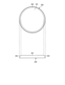
ここで、図2は被検査物体300を例示的に示す図である。図2に示すように、本実施形態の被検査物体300は、厚みのある立体的な円盤形状である。被検査物体300は、平板形状の平坦面301と、平坦面301から湾曲するエッジ領域面302とを有している。平坦面301は、エンボス加工が施されている。
Here, FIG. 2 is a diagram exemplarily showing the object to be inspected 300. As shown in FIG. 2, the object to be inspected 300 of this embodiment has a thick three-dimensional disk shape. The object to be inspected 300 has a
被検査物体300は、その表面に対して、ユーザの嗜好に合わせた様々なデザインをインクジェットプリンタ等の印刷装置によって印刷される。検査装置100は、被検査物体300に印刷されたデザイン画像の印刷品質等を検査する。
The surface of the object to be inspected 300 is printed with various designs that match the user's preferences using a printing device such as an inkjet printer. The
なお、被検査物体300は、円盤形状に限るものではなく、矩形形状等であってもよい。被検査物体300は、缶バッジ、スマートフォンをカバーするスマートフォンカバー、スマートフォン等に取り付ける落下防止用のグリップなどが想定される。 Note that the object to be inspected 300 is not limited to a disk shape, but may have a rectangular shape or the like. The object to be inspected 300 is assumed to be a tin badge, a smartphone cover that covers a smartphone, a grip to prevent falling that is attached to a smartphone, or the like.
図3は、検査装置100の構成を示す図である。図3に示すように、検査装置100は、アルミフレームで構成された本体フレーム101を備えている。本体フレーム101は、四角柱形状に形成されている。
FIG. 3 is a diagram showing the configuration of the
本体フレーム101は、鉛直方向の上方から順に、撮像装置102、第1の照明装置である第1リング照明装置103、第2の照明装置である第2リング照明装置104、第3の照明装置であるバックライト照明装置105を垂直方向に並べて備えている。
The
加えて、本体フレーム101は、第2リング照明装置104とバックライト照明装置105との間にスライドステージ106を備えている。
In addition, the
撮像装置102は、例えばCMOS(Complementary Metal Oxide Semiconductor)を用いたカメラであって、投射された光に応じた信号を出力する。なお、撮像装置102は、CCD(Charge Coupled Device)用いたカメラを適用してもよい。
The
ここで、図4は各照明装置のレイアウト構成を示す図である。 Here, FIG. 4 is a diagram showing the layout configuration of each lighting device.
第1リング照明装置103は、第1の本体部であるリング形状の本体部103aを有している。本体部103aがリング形状であることにより、撮像装置102による被検査物体300の撮像が可能である。第1リング照明装置103は、リング形状の本体部103aの下面に、第1の光源である多数のLED103bを備えている。多数のLED103bは、撮像装置102の撮像位置に位置する被検査物体300に対して、上方(鉛直方向)から光を照射する。
The first
図4に示すように、第1リング照明装置103からの光は、被検査物体300の平坦面301において、撮像装置102に対する正反射光および拡散反射光となる。また、第1リング照明装置103からの光は、被検査物体300のエッジ領域面302において、撮像装置102に対する拡散反射光となる。
As shown in FIG. 4, the light from the first
なお、第1リング照明装置103は、リング形状の本体部103aを備えるようにしたが、これに限るものではない。例えば、第1リング照明装置103は、複数の断片形状の照明をリング状に並べたり、複数(例えば4つ)の小型照明を平面視での円周上の上下左右の位置に配置したりするものであってもよい。
Note that although the first
第2リング照明装置104は、第2の本体部であるリング形状の本体部104aを有している。本体部104aがリング形状であることにより、撮像装置102による被検査物体300の撮像が可能である。第2リング照明装置104は、リング形状の本体部104aの内壁に、光源である多数のLED104bを備えている。リング形状の本体部104aの内壁は、上方から下方に向けて開口が広がるようなテーパー形状となっている。多数のLED104bは、撮像装置102の撮像位置に位置する被検査物体300に対して、鉛直方向に対して斜め方向(例えば、30度)から光を照射する。
The second
図4に示すように、第2リング照明装置104からの光は、被検査物体300の平坦面301において、撮像装置102に対する正反射光および拡散反射光となる。また、第2リング照明装置104からの光は、被検査物体300のエッジ領域面302において、撮像装置102に対する正反射光および拡散反射光となる。
As shown in FIG. 4, the light from the second
なお、第2リング照明装置104は、リング形状の本体部104aを備えるようにしたが、これに限るものではない。例えば、第2リング照明装置104は、複数の断片形状の照明をリング状に並べたり、複数(例えば4つ)の小型照明を平面視での円周上の上下左右の位置に配置したりするものであってもよい。
Although the second
なお、バックライト照明装置105からの光は、被検査物体300の平坦面301において、撮像装置102に対する拡散反射光となる。また、バックライト照明装置105からの光は、被検査物体300のエッジ領域面302において、撮像装置102に対する正反射光および拡散反射光となる。
Note that the light from the
そこで、本実施の形態においては、第1リング照明装置103は、被検査物体300のエッジ領域面302を撮像するための照明として機能させる。また、第2リング照明装置104は、被検査物体300の平坦面301(エッジ領域面302の内側)を撮像するための照明として機能させる。なお、バックライト照明装置105は、被検査物体300の領域を認識するための照明として機能させる。
Therefore, in this embodiment, the first
そして、本実施の形態においては、第1リング照明装置103で照明して撮像装置102で撮像した撮像画像と、第2リング照明装置104で照明して撮像装置102で撮像した撮像画像とを合成することで、被検査物体300の全域画像を取得するようにする。
In the present embodiment, a captured image illuminated by the first
次に、スライドステージ106について説明する。スライドステージ106は、被検査物体300を撮像装置102の撮像位置にガイドするガイド部材である。
Next, the
図5は、スライドステージ106を上方から見た状態を示す図である。図5に示すように、スライドステージ106は、2個の被検査物体300を保持可能である。スライドステージ106は、スライド機構によって左右に移動することで、交互に被検査物体300を撮像装置102の撮像位置に移動する。
FIG. 5 is a diagram showing the
図3に示すように、スライドステージ106は、ラチェット機構106aを有している。スライドステージ106は、ラチェット機構106aによって撮像装置102の撮像位置に被検査物体300を固定させる。
As shown in FIG. 3, the
図3に示すように、スライドステージ106は、センサ106b,106cを有している。センサ106b,106cは、非接触センサである。撮像装置102の撮像位置に右側の被検査物体300が固定された場合、センサ106bがONする。一方、撮像装置102の撮像位置に左側の被検査物体300が固定された場合、センサ106cがONする。
As shown in FIG. 3, the
なお、スライドステージ106の動作は、左右に設けられているアブソーバー106dで緩和される。
Note that the movement of the
なお、本実施形態においては、被検査物体300を撮像装置102の撮像位置にガイドするガイド部材として、スライド式のスライドステージ106を適用したが、これに限るものではない。例えば、ガイド部材としては、被検査物体300を撮像装置102の撮像位置に回転させながらガイドするレボルバー式であってもよい。
Note that in this embodiment, the sliding
次に、検査システム1の電装系の接続について説明する。
Next, the connection of the electrical system of the
図6は、検査システム1の電装系の接続を示すブロック図である。図6に示すように、検査装置100は、I/O電源ボックス107と、光源電源ボックス108と、を備えている。情報処理装置200は、I/O電源ボックス107を介して検査装置100に接続される。
FIG. 6 is a block diagram showing connections of the electrical system of the
第1リング照明装置103、第2リング照明装置104、バックライト照明装置105は、I/O電源ボックス107および光源電源ボックス108を介して、情報処理装置200に接続される。第1リング照明装置103、第2リング照明装置104、バックライト照明装置105は、情報処理装置200によって、LED照明点灯制御と、LED照明点灯パワー制御とを実行される。
The first
撮像装置102は、情報処理装置200に直接接続され、制御される。
The
スライドステージ106のセンサ106b,106cは、I/O電源ボックス107を介して、情報処理装置200に接続される。スライドステージ106のセンサ106b,106cは、情報処理装置200によって、信号検知を実行される。
次に、情報処理装置200のハードウェア構成について説明する。
Next, the hardware configuration of the
図7は、情報処理装置200のハードウェア構成図である。
FIG. 7 is a hardware configuration diagram of the
図7に示されているように、情報処理装置200は、コンピュータによって構築されており、図7に示されているように、CPU501、ROM502、RAM503、HD504、HDD(Hard Disk Drive)コントローラ505、ディスプレイ506、外部機器接続I/F(Interface)508、ネットワークI/F509、バスライン510、キーボード511、ポインティングデバイス512、DVD-RW(Digital Versatile Disk Rewritable)ドライブ514、メディアI/F516を備えている。
As shown in FIG. 7, the
これらのうち、CPU501は、情報処理装置200全体の動作を制御する。ROM502は、IPL等のCPU501の駆動に用いられるプログラムを記憶する。RAM503は、CPU501のワークエリアとして使用される。HD504は、プログラム等の各種データを記憶する。HDDコントローラ505は、CPU501の制御にしたがってHD504に対する各種データの読み出し又は書き込みを制御する。ディスプレイ506は、カーソル、メニュー、ウィンドウ、文字、又は画像などの各種情報を表示する。外部機器接続I/F508は、各種の外部機器を接続するためのインターフェースである。この場合の外部機器は、例えば、USB(Universal Serial Bus)メモリやプリンタ等である。ネットワークI/F509は、通信ネットワーク100を利用してデータ通信をするためのインターフェースである。バスライン510は、図7に示されているCPU501等の各構成要素を電気的に接続するためのアドレスバスやデータバス等である。
Among these, the
また、キーボード511は、文字、数値、各種指示などの入力のための複数のキーを備えた入力手段の一種である。ポインティングデバイス512は、各種指示の選択や実行、処理対象の選択、カーソルの移動などを行う入力手段の一種である。DVD-RWドライブ514は、着脱可能な記録媒体の一例としてのDVD-RW513に対する各種データの読み出し又は書き込みを制御する。なお、DVD-RWに限らず、DVD-R等であってもよい。メディアI/F516は、フラッシュメモリ等の記録メディア515に対するデータの読み出し又は書き込み(記憶)を制御する。
Further, the
本実施形態の情報処理装置200で実行されるプログラムは、インストール可能な形式又は実行可能な形式のファイルでCD-ROM、フレキシブルディスク(FD)、CD-R、DVD(Digital Versatile Disk)等のコンピュータで読み取り可能な記録媒体に記録されて提供される。
The program executed by the
また、本実施形態の情報処理装置200で実行されるプログラムを、インターネット等のネットワークに接続されたコンピュータ上に格納し、ネットワーク経由でダウンロードさせることにより提供するように構成しても良い。また、本実施形態の情報処理装置200で実行されるプログラムをインターネット等のネットワーク経由で提供または配布するように構成しても良い。
Further, the program executed by the
以下において、情報処理装置200のCPU501がプログラムにより実行する各種の演算処理のうち、本実施形態の特長的な処理について説明する。
Below, among the various calculation processes executed by the
ここで、図8は情報処理装置200の機能構成を示す機能ブロック図である。図8に示すように、情報処理装置200のCPU501は、プログラムを実行することにより、第1の画像取得部201と、第2の画像取得部202と、第3の画像取得部203と、画像合成部204と、照度設定部205と、識別部206と、閾値切替部207と、検査部208と、を実現する。
Here, FIG. 8 is a functional block diagram showing the functional configuration of the
第1の画像取得部201は、第1リング照明装置103より光を照射して撮像装置102によって撮像した撮像画像(拡散反射照明画像)から、検査対象物の第1の検査対象画像として被検査物体300のエッジ領域面302の画像を取得する。
The first
第2の画像取得部202は、第2リング照明装置104より光を照射して撮像装置102によって撮像した撮像画像(正反射照明画像)から、検査対象物の第2の検査対象画像として被検査物体300のエッジ領域面302を除く平坦面301の画像を取得する。
The second
第3の画像取得部203は、バックライト照明装置105より光を照射して撮像装置102によって撮像した撮像画像(シルエット画像)から、被検査物体300の領域を示す画像を取得する。
The third
画像合成部204は、被検査物体300のエッジ領域面302の画像と、被検査物体300の平坦面301の画像と、被検査物体300の領域を示す画像と、を合成した合成画像を検査対象画像とする。なお、画像合成部204は、被検査物体300のエッジ領域面302の画像と、被検査物体300の平坦面301の画像とを合成した合成画像を検査対象画像してもよい。
The
照度設定部205は、第1リング照明装置103および第2リング照明装置104の照度設定を行う。
The
識別部206は、被検査物体300にかかるマスタ画像(基準データ)を解析し、所定のパターンの有無を識別する。ここで、所定のパターンは、例えば、被検査物体300の形状に類似しているパターンである。また、所定のパターンは、例えば、点対象もしくは線対象に類似しているパターンである。
The
閾値切替部207は、識別部206におけるマスタ画像の画像種別の識別結果に応じて、被検査物体300にかかるマスタ画像(基準データ)と検査対象画像とを検査部208において比較する際の閾値を切り替える。ここで、閾値は、判断基準、判断要件等の上位概念の一例である。
The threshold
検査部208は、被検査物体300にかかるマスタ画像(基準データ)と検査対象画像とを比較して検査する。より詳細には、検査部208は、検査対象画像の印刷品質を検査する場合、検査対象画像のOff-Centerを判断するための閾値を用いる。そして、検査部208は、所定の閾値を満たさない場合において、検査対象画像がOff-Centerであるとして、欠陥と判定する。
The
次に、本実施の形態にかかる情報処理装置200が行う処理のうち特徴的な処理の流れについて説明する。
Next, a characteristic process flow among the processes performed by the
まず、情報処理装置200のCPU501による第1リング照明装置103と第2リング照明装置104との2つの照明装置の照度設定処理について説明する。図9は、照度設定処理の流れを示すフローチャートである。
First, illuminance setting processing for two lighting devices, the first
なお、照度設定処理は、平坦面301とエッジ領域面302とが同一色(例えば、白色)の被検査物体300を対象とする。
Note that the illuminance setting process targets an object to be inspected 300 in which the
図9に示すように、照度設定部205は、第1リング照明装置103および撮像装置102を制御して(ステップS1)、第1リング照明装置103による照明によって被検査物体300を撮像したエッジ領域面302の撮像画像の信号レベル(レベルA)を取得する(ステップS2)。
As shown in FIG. 9, the
次に、照度設定部205は、第2リング照明装置104および撮像装置102を制御して(ステップS3)、第2リング照明装置104による照明による照明によって被検査物体300を撮像した平坦面301の撮像画像の信号レベル(レベルB)を取得する(ステップS4)。
Next, the
次に、照度設定部205は、ステップS2で取得したレベルAとステップS4で取得したレベルBとが同じになるよう、第1リング照明装置103および第2リング照明装置104の照度を設定する(ステップS5)。例えば、照度設定部205は、ステップS2で取得したレベルAとステップS4で取得したレベルBとが同じになるよう、撮像画像信号の補正係数(レベルA/レベルB)を算出する。補正係数は、実際の検査時において、第2リング照明装置104による撮像画像の補正に用いられる。
Next, the
なお、本実施形態においては、第1リング照明装置103と第2リング照明装置104との2つの照明装置の照度設定処理について説明したが、これに限るものではなく、撮像装置102のピント調整なども可能である。
Note that in this embodiment, the illuminance setting process of two lighting devices, the first
次に、情報処理装置200のCPU501による画像合成処理について説明する。ここで、図10は画像合成処理の流れを示すフローチャート、図11は画像合成の一例を示す図である。
Next, image composition processing by the
図10に示すように、第3の画像取得部203は、まず、バックライト照明装置105および撮像装置102を制御して(ステップS11)、バックライト照明装置105による照明によって被検査物体300を撮像した撮像画像(シルエット画像)から、被検査物体300の領域を認識する(ステップS12)。
As shown in FIG. 10, the third
より詳細には、ステップS12において、第3の画像取得部203は、被検査物体300の設置位置計測(x,y)、被検査物体300の円形サイズ算出、被検査物体300の背景画像領域確定、被検査物体300の設置不良判定などを行う。
More specifically, in step S12, the third
次に、第1の画像取得部201は、第1リング照明装置103および撮像装置102を制御して(ステップS13)、第1リング照明装置103による照明によって被検査物体300を撮像した撮像画像(拡散反射照明画像)から、被検査物体300のエッジ領域面302の画像を取得する(ステップS14)。
Next, the first
より詳細には、ステップS13において、第1の画像取得部201は、4枚の被検査物体300を撮像した撮像画像(拡散反射照明画像)を得る。そして、ステップS14において、第1の画像取得部201は、4枚の撮像画像(拡散反射照明画像)に基づいて画像平均化処理を施した後、被検査物体300のエッジ領域面302の画像を記録する。
More specifically, in step S13, the first
次に、第2の画像取得部202は、第2リング照明装置104および撮像装置102を制御して(ステップS15)、第2リング照明装置104による照明によって被検査物体300を撮像した撮像画像(正反射照明画像)から、被検査物体300の平坦面301の画像を取得する(ステップS16)。
Next, the second
より詳細には、ステップS15において、第2の画像取得部202は、4枚の被検査物体300を撮像した撮像画像(正反射照明画像)を得る。そして、ステップS16において、第2の画像取得部202は、4枚の撮像画像(正反射照明画像)に基づいて画像平均化処理を施した後、被検査物体300の平坦面301の画像を記録する。
More specifically, in step S15, the second
なお、ステップS13からステップS16の処理は、上述のフローチャートに示した順序に限るものではない。例えば、第2の画像取得部202が、第2リング照明装置104および撮像装置102を制御して(ステップS15)、被検査物体300の平坦面301の画像を取得した後(ステップS16)、第1の画像取得部201が、第1リング照明装置103および撮像装置102を制御して(ステップS13)、被検査物体300のエッジ領域面302の画像を取得する(ステップS14)ようにしてもよい。
Note that the processing from step S13 to step S16 is not limited to the order shown in the above-described flowchart. For example, the second
最後に、画像合成部204は、ステップS12で認識した被検査物体300の領域と、ステップS14で取得した被検査物体300のエッジ領域面302の画像と、ステップS16で取得した被検査物体300の平坦面301の画像とを合成する(ステップS17)。
Finally, the
画像合成部204は、ステップS17における画像合成処理において、x,y軸中心パターンマッチング、回転角度取得、x,y中心アフィン変換処理、リサンプリングなどを行う。また、画像合成部204は、ステップS17における画像合成処理において、合成画像に階調補正を加える階調補正処理も行う。
The
以上のようにして生成された合成画像は、被検査物体300の検査対象画像として例えば印刷品質の検査のためにマスタ画像との比較に供される。
The composite image generated as described above is used as an image to be inspected of the
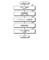
次に、情報処理装置200のCPU501による画像種識別処理について説明する。ここで、図12は画像種識別処理の流れを示すフローチャートである。
Next, image type identification processing by the
図12に示すように、識別部206は、RIP(Raster Image Processer)処理したデータ(CMYK)を取得し(ステップS21)、取得したRIPデータをCMYKからRGBにカラーモード変換する(ステップS22)。
As shown in FIG. 12, the
次いで、識別部206は、平滑化処理などのプリンタエミュレート用前処理を実行する(ステップS23)。
Next, the
次いで、識別部206は、被検査物体300にかかる画像の画像種別を識別する画像種別識別処理を実行し(ステップS24)、マスタ画像を生成する(ステップS25)。ステップS24における画像種別識別処理が必要な理由について、以下において説明する。
Next, the
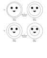
被検査物体300にかかる検査対象画像の印刷品質を検査員の目視で判断する場合、絵柄の外周・内周の状態によって画像のOff-Centerの判断閾値が異なってしまう。画像のOff-Centerとは、画像が中心を外れていることをいう。特に、検査員は、円盤形状の被検査物体300において同形状のサークルを有する絵柄について、画像のOff-Centerを厳しく判断してしまう。例えば、図13は絵柄の種別例を示す図である。図13に示すように、円盤形状の被検査物体300において同形状のサークルを有する絵柄の種別例としては、下記に示すType1~Type3の4種類が挙げられる。
When the print quality of the image to be inspected on the object to be inspected 300 is visually judged by an inspector, the off-center judgment threshold of the image differs depending on the condition of the outer periphery and inner periphery of the image. Off-Center of an image means that the image is off-center. In particular, the inspector judges severely the off-center of the image for a pattern having circles of the same shape in the disk-shaped object to be inspected 300. For example, FIG. 13 is a diagram showing examples of the types of patterns. As shown in FIG. 13, examples of the types of patterns having circles of the same shape in the disk-shaped object to be inspected 300 include the following four types:
Type0は、絵が一面に印刷されている「Normal」タイプである。
Type1~Type3の違いは、絵柄の外周・内周の状態によって、検査対象画像の印刷品質を検査する場合における判断閾値を変える点である。ここで、図14は外周・内周の状態による絵柄の例を示す図である。図14に示すように、Type1~Type3の基準としては、絵柄の外周色の色数と、内周色の支配色とが挙げられる。
The difference between
Type1は、外周に近い円があり、ベタ領域がある「Circle」タイプである。図14に示すように、Type1は、外周が1色であり、内周は外周色とは別色である。
Type2は、外周に近い円はあるが、ベタ領域はない「Circle&Picture」タイプである。図14に示すように、Type2は、外周が1色であり、内周は外周色とは同色である。
Type3は、一面に印刷されている絵の中に円がある「Circle in Picture」タイプである。図14に示すように、Type3は、外周が複数色であり、内周は外周色とは別色である。なお、Type2とType3は、ベタ量の比率で変えるのでもよい。
検査対象画像の印刷品質としてOff-Centerを検査員の目視で判断する場合、検査員は、検査対象画像の外周色の幅を線/点対象の位置で比較し、線/点対象位置の外形との幅が一致しているかをそれぞれ判断する(左右、上下、斜め位置など)。図15は、幅同士の比較の難度を示す図である。幅同士の比較が簡単なものほど、厳しい検査が必要になる。図15(a)に示すように、Type0は、Type2よりも幅同士の比較が難しいものである。また、図15(b)に示すように、Type2は、Type1よりも幅同士の比較が難しいものである。また、図15(c)に示すように、Type3は、Type1よりも幅同士の比較が難しいものである。
When an inspector visually judges Off-Center as the print quality of an image to be inspected, the inspector compares the width of the outer circumferential color of the image to be inspected at the position of the line/dot object, and determines the outline of the line/dot object position. Determine whether the width matches each other (left/right, top/bottom, diagonal position, etc.). FIG. 15 is a diagram showing the difficulty level of comparing widths. The easier it is to compare widths, the more rigorous inspection is required. As shown in FIG. 15A,
ここで、図16は、検査対象画像の印刷品質としてOff-Centerを検査する場合における判断閾値の一例を示す図である。上述したように、Type1の絵柄については検査員による検査対象画像の外周色の幅同士の比較が容易であるため、Type2の絵柄やType3の絵柄よりもより厳しい検査が必要となる。また、Type2の絵柄は、Type3の絵柄よりもより厳しい検査が必要となる。
Here, FIG. 16 is a diagram illustrating an example of the determination threshold value when Off-Center is inspected as the print quality of the image to be inspected. As described above, since it is easy for an inspector to compare the widths of the outer circumferential colors of images to be inspected for
そこで、本実施形態においては、被検査物体300の絵柄のパターンを識別し、パターンのタイプ(Normal/Circle/Circle & Picture/Circle in Picture)に適した方式でOff-Centerの検査を実施するようにしたものである。 Therefore, in this embodiment, the pattern of the picture of the object to be inspected 300 is identified, and off-center inspection is performed using a method suitable for the pattern type (Normal/Circle/Circle & Picture/Circle in Picture). This is what I did.
次に、情報処理装置200のCPU501による画像比較による検査処理について説明する。ここで、図17は画像比較による検査処理の流れを示すフローチャートである。
Next, inspection processing by image comparison performed by the
図17に示すように、検査部208は、マスタ画像(RGB)と検査対象画像(RGB)とを取得し(ステップS31)、マスタ画像と検査対象画像とを回転または平行移動させて位置合わせを行う(ステップS32)。
As shown in FIG. 17, the
次いで、検査部208は、マスタ画像と検査対象画像とを比較し、Off-Centerを検出る検査を実行する(ステップS33)。ここで、閾値切替部207は、識別部206におけるマスタ画像の画像種別の識別結果に応じて、被検査物体300にかかるマスタ画像と検査対象画像とを比較する際の閾値を切り替える。
Next, the
より詳細には、閾値切替部207は、ユーザが予め指定した位置ずれを許容する閾値(ThNormal)から、下記式に従って画像種別毎の閾値(Th)を求める。
Th=CType×ThNormal
More specifically, the threshold
Th=C Type ×Th Normal
閾値切替部207は、識別部206で識別したマスタ画像の画像種別に応じて係数CTypeを算出する。ここで、図18は画像種別に応じた係数CTypeを例示的に示す図である。図18に示すように、閾値切替部207は、画像種別に応じた係数CTypeを取得する。係数CTypeは、厳しい検査が必要となる画像種別ほど値が小さくなっている。したがって、厳しい検査が必要となる画像種別ほど閾値(Th)が小さくなる。
The threshold
次いで、検査部208は、Off-Centerを検出した検査結果を、描画する(ステップS34)。
Next, the
ここで、図19はOff-Centerを検出した検査結果例を示す図である。図19に示すように、検査部208は、検査結果として円形状で位置ずれを描画した画像を、ディスプレイ506に表示する。図19に示すように、検査部208は、マスタ画像から検出された情報である被検査物体300の外形(エッジ)を太線1で、マスタ画像と検査対象画像との比較結果から得られた情報であるOff-Centerだけずらした検査対象画像の外周(エッジ)を太線2で重ねて表示している。また、検査部208は、検査物体300の中心を点線1で、Off-Centerだけずらした検査対象画像の中心を点線2で重ねて表示している。
Here, FIG. 19 is a diagram showing an example of an inspection result in which Off-Center was detected. As shown in FIG. 19, the
なお、本実施形態においては、マスタ画像から検出された情報である被検査物体300の外形(エッジ)と、マスタ画像と検査対象画像との比較結果から得られた情報であるOff-Centerだけずらした検査対象画像の外周(エッジ)とを重ねて表示するようにしたが、これに限るものではなく、マスタ画像から検出された情報である被検査物体300の外形の中心と、マスタ画像と検査対象画像との比較結果から得られた情報であるOff-Centerだけずらした検査対象画像の外周の中心を、重ねて表示するようにしてもよい。 In this embodiment, only the outer shape (edge) of the object to be inspected 300, which is information detected from the master image, and the Off-Center, which is information obtained from the comparison result between the master image and the image to be inspected, are shifted. Although the outer periphery (edge) of the image to be inspected and the outer periphery (edge) of the image to be inspected are displayed superimposed, the display is not limited to this. The center of the outer periphery of the inspection target image shifted by Off-Center, which is information obtained from the comparison result with the target image, may be displayed in an overlapping manner.
このように両情報を重ねて表示することで、Off-Centerの結果をわかりやすく見せることができるので、印刷時の位置ズレをわかりやすく示すことができる。 By displaying both pieces of information in an overlapping manner in this way, it is possible to clearly show the Off-Center results, making it possible to clearly show the positional deviation during printing.
最後に、検査部208は、Off-Centerを検出した検査結果に基づいて、検査対象画像の位置ずれが許容されるか否かをディスプレイ506に表示するなどして報知して(ステップS35)、処理を終了する。
Finally, the
このように本実施形態によれば、印刷するマスタ画像(基準データ)を解析することにより、所定のパターン(被検査物体300の形状(例えば、円形状の媒体)に類似しているパターン(例えば、円形状のパターン))の有無を識別し、その識別結果に応じて、マスタ画像(基準データ)と検査対象画像とを検査部208において比較する際の閾値を切り替える。これにより、被検査物体300の印刷パターンの影響も加味して適切に印刷時の位置ズレ検査の感度を切り替えるので、検査物のデザインバリエーションが多数の場合であっても、検査員の負担を軽減して効率的に検査を実施することができる。
As described above, according to the present embodiment, by analyzing the master image (reference data) to be printed, a predetermined pattern (a pattern similar to the shape of the object to be inspected 300 (for example, a circular medium) (for example, , circular pattern)), and depending on the identification result, the threshold value used when comparing the master image (reference data) and the image to be inspected in the
なお、本実施形態によれば、円形状の被検査物体300に対して類似しているパターン(例えば、円形状のパターンを有する絵柄)を印刷する例について説明したが、これに限るものではなく、多角形形状の被検査物体300に対して類似しているパターン(例えば、多角形形状のパターンを有する絵柄)を印刷するものであってもよい。また、絵柄は、被検査物体300の形状に類似していなくてもよい。例えば、円形状の被検査物体300に対して多角形形状のパターンを有する絵柄を印刷する場合でも、適用可能である。また、絵柄自身が左右対称・上下対称のパターンの場合でも、同様の処理が適用可能である。
According to the present embodiment, an example has been described in which a similar pattern (for example, a pattern having a circular pattern) is printed on the circular object to be inspected 300, but the present invention is not limited to this. Alternatively, a pattern similar to the polygonal inspected object 300 (for example, a picture having a polygonal pattern) may be printed. Further, the pattern does not have to be similar to the shape of the object to be inspected 300. For example, the present invention is applicable even when printing a pattern having a polygonal pattern on the
(第2の実施の形態)
次に、第2の実施の形態について説明する。
(Second embodiment)
Next, a second embodiment will be described.
第2の実施の形態は、認識した円(内周)の直径も考慮して画像種別毎の閾値(Th)を求めるようにした点が、第1の実施の形態と異なる。以下、第2の実施の形態の説明では、第1の実施の形態と同一部分の説明については省略し、第1の実施の形態と異なる箇所について説明する。 The second embodiment differs from the first embodiment in that the threshold value (Th) for each image type is determined by also taking into account the diameter of the recognized circle (inner circumference). Hereinafter, in the description of the second embodiment, description of the same parts as the first embodiment will be omitted, and only parts different from the first embodiment will be described.
図20は、第2の実施の形態にかかる円の直径に応じた幅同士の比較の難度を示す図である。幅同士の比較が簡単なものほど、厳しい検査が必要になる。図20(a)(b)に示すように、例えばType1の内周の直径は、小さくなるほど、すなわち外周から遠くなるほど、幅同士の比較が難しいものである。すなわち、内周の直径が大きくなるほど、より厳しい検査が必要となる。
FIG. 20 is a diagram showing the degree of difficulty in comparing widths according to the diameters of circles according to the second embodiment. The easier it is to compare widths, the more rigorous inspection is required. As shown in FIGS. 20A and 20B, for example, the smaller the diameter of the inner circumference of
そこで、本実施形態では、認識した円(内周)の直径も考慮して画像種別毎の閾値(Th)を求めるようにしたものである。 Therefore, in this embodiment, the threshold value (Th) for each image type is determined by also taking into account the diameter of the recognized circle (inner circumference).
ここで、図21は内周円の直径に応じた閾値係数を例示的に示す図である。図21に示すように、閾値切替部207は、内周円に応じた係数CSizeを取得する。係数CSizeは、厳しい検査が必要となる大きな直径ほど値が小さくなっている。したがって、厳しい検査が必要となる大きな直径の内周円ほど閾値(Th)が小さくなる。
Here, FIG. 21 is a diagram illustrating threshold coefficients according to the diameter of the inner circumferential circle. As shown in FIG. 21, the
したがって、閾値切替部207は、図17に示したステップS33において、下記式に従って画像種別毎の閾値(Th)を求めることになる。
Th=CType×CSize×ThNormal
Therefore, in step S33 shown in FIG. 17, the threshold
Th=C Type ×C Size ×Th Normal
このように本実施形態によれば、検査の精度を高めることができる。 In this way, according to this embodiment, the accuracy of inspection can be improved.
(第3の実施の形態)
次に、第3の実施の形態について説明する。
(Third embodiment)
Next, a third embodiment will be described.
第3の実施の形態は、マスタ画像(基準データ)の入稿デザインが適正か否かを分かり易く見せるようにした点が、第1の実施の形態または第2の実施の形態と異なる。以下、第3の実施の形態の説明では、第1の実施の形態または第2の実施の形態と同一部分の説明については省略し、第1の実施の形態または第2の実施の形態と異なる箇所について説明する。 The third embodiment differs from the first embodiment or the second embodiment in that it is made easy to see whether the submitted design of the master image (reference data) is appropriate. In the following description of the third embodiment, descriptions of parts that are the same as those of the first embodiment or the second embodiment will be omitted, and differences from the first embodiment or the second embodiment will be omitted. Explain the parts.
図22は、第3の実施の形態にかかる入稿チェック例を示す図である。検査部208は、Off-Centerを検出した検査結果と併せて、入稿されたデザインがどのような状態であったかを報知する。このような報知を行うのは、入稿されたデザインが後述する印刷ガイドライン(印刷領域の範囲)と同じ場合、あるいは印刷ガイドライン(印刷領域の範囲)よりも小さい場合にOff-Centerが発生しやすいため、印刷ガイドラインよりも大きな絵柄を作成することを知らしめるためである。また、予め印刷のズレ量が予測できる場合は、印刷領域の範囲+ズレ量よりも小さい場合にデザイナや検査員に報知するようにしてもよい。
FIG. 22 is a diagram illustrating an example of input check according to the third embodiment. The
図22に示すように、検査部208は、マスタ画像から検出された情報である被検査物体300の絵柄の外周(エッジ)に対して、印刷ガイドライン(被検査物体300の外形(点線1、位置ずれが0の位置(点線2)、被検査物体300の絵柄の外周(エッジ)(点線3))を重ねてディスプレイ506に表示している。また、検査部208は、マスタ画像から検出された情報である被検査物体300の外形の中心を示す点線4もディスプレイ506に表示している。
As shown in FIG. 22, the
ここで、印刷ガイドライン(印刷領域の範囲)は、印刷領域の外周を示すものである。したがって、マスタ画像から検出された被検査物体300の絵柄の外周(エッジ)が印刷ガイドライン(印刷領域の範囲)と同じ場合、あるいは印刷ガイドライン(印刷領域の範囲)よりも小さい場合には、検査員は、被検査物体300の絵柄が小さく適切でないことがわかる。
Here, the print guideline (range of print area) indicates the outer periphery of the print area. Therefore, if the outer periphery (edge) of the pattern of the inspected
また、印刷ガイドライン(印刷領域の中心)は、印刷領域の中心を示すものである。したがって、マスタ画像から検出された被検査物体300の絵柄の中心が印刷ガイドライン(印刷領域の中心)からずれている場合には、検査員は、被検査物体300の絵柄がずれており適切でないことがわかる。また、元々中心からずれていたデザインの場合でも、印刷領域の中心を示すことで、被検査物体300の絵柄がずれており適切ではないことあるいは被検査物体300の絵柄が適切であることを、検査員はデザインのズレに影響されずに正しく判断することができる。 Further, the print guideline (center of print area) indicates the center of the print area. Therefore, if the center of the pattern of the object to be inspected 300 detected from the master image deviates from the printing guideline (the center of the print area), the inspector can determine that the pattern of the object to be inspected 300 is deviated and inappropriate. I understand. In addition, even in the case of a design that is originally off-center, by indicating the center of the printing area, you can confirm that the pattern of the object to be inspected 300 is off-center and inappropriate, or that the pattern of the object to be inspected 300 is appropriate. Inspectors can make correct judgments without being affected by design discrepancies.
このように本実施形態によれば、マスタ画像(基準データ)に印刷ガイドラインを重ねて見せることで、マスタ画像(基準データ)の問題(例えば、印刷領域が小さく適切でない、印刷領域の中心がズレている)をわかりやすく示すことができる。 In this way, according to the present embodiment, by overlaying the print guideline on the master image (reference data), problems with the master image (reference data) (for example, the print area is small and inappropriate, the center of the print area is misaligned) can be solved. ) can be shown in an easy-to-understand manner.
上記で説明した実施形態の各機能は、一又は複数の処理回路によって実現することが可能である。ここで、本明細書における「処理回路」とは、電子回路により実装されるプロセッサのようにソフトウェアによって各機能を実行するようプログラミングされたプロセッサや、上記で説明した各機能を実行するよう設計されたASIC(Application Specific Integrated Circuit)、DSP(Digital Signal Processor)、FPGA(Field Programmable Gate Array)や従来の回路モジュール等のデバイスを含むものとする。 Each function of the embodiments described above can be realized by one or more processing circuits. Here, the term "processing circuit" as used herein refers to a processor programmed to execute each function by software, such as a processor implemented by an electronic circuit, or a processor designed to execute each function explained above. This includes devices such as ASICs (Application Specific Integrated Circuits), DSPs (Digital Signal Processors), FPGAs (Field Programmable Gate Arrays), and conventional circuit modules.
実施例に記載された装置群は、本明細書に開示された実施形態を実施するための複数のコンピューティング環境のうちの1つを示すものにすぎない。ある実施形態では、情報処理装置200は、サーバクラスタといった複数のコンピューティングデバイスを含む。複数のコンピューティングデバイスは、ネットワークや共有メモリなどを含む任意のタイプの通信リンクを介して互いに通信するように構成されており、本明細書に開示された処理を実施する。同様に、情報処理装置200は、互いに通信するように構成された複数のコンピューティングデバイスを含むことができる。
The devices described in the Examples are merely illustrative of one of several computing environments for implementing the embodiments disclosed herein. In some embodiments,
1 検査システム
200 情報処理装置
201~203 画像取得部
206 識別部
207 閾値切替部
208 検査部
300 検査対象物
1
Claims (15)
検査対象物にかかるマスタ画像に所定のパターンが円盤形状の物体に対する円形状の絵柄の大きさが異なる複数のタイプのいずれのタイプで有るかを識別する識別部と、
撮像装置によって撮像した撮像画像から、前記検査対象物の検査対象画像を取得する画像取得部と、
前記検査対象物にかかるマスタ画像と検査対象画像とを比較して、検査対象画像の中心ずれを検査する検査部と、
前記識別部における識別結果に応じて、前記検査対象物にかかるマスタ画像と検査対象画像とを前記検査部において比較する際の円形状の絵柄の中心ずれの閾値を切り替える閾値切替部と、
を備えることを特徴とする検査システム。 In an inspection system that performs inspection using an inspection image of an inspection target,
an identification unit that identifies which type of a predetermined pattern in the master image of the object to be inspected is among a plurality of types having different sizes of circular patterns for the disk-shaped object ;
an image acquisition unit that acquires an inspection target image of the inspection target from a captured image captured by an imaging device;
an inspection unit that compares a master image related to the inspection object with the inspection target image to inspect center deviation of the inspection target image ;
a threshold switching unit that switches a threshold for center deviation of a circular pattern when comparing a master image of the inspection object and an inspection target image in the inspection unit according to the identification result in the identification unit;
An inspection system comprising:
ことを特徴とする請求項1に記載の検査システム。 the predetermined pattern is a pattern of the shape of the inspection object;
The inspection system according to claim 1, characterized in that:
ことを特徴とする請求項1に記載の検査システム。 The predetermined pattern is a point- symmetric or line- symmetric pattern,
The inspection system according to claim 1, characterized in that:
ことを特徴とする請求項1に記載の検査システム。 The master image of the inspection object is print data;
The inspection system according to claim 1, characterized in that:
ことを特徴とする請求項1に記載の検査システム。 The inspection unit determines that there is a defect if the threshold value is not satisfied as a comparison result.
The inspection system according to claim 1, characterized in that:
ことを特徴とする請求項1ないし5の何れか一項に記載の検査システム。 The inspection unit displays information detected from a master image of the object to be inspected and information obtained from a comparison result between the master image of the object to be inspected and the image to be inspected, in a superimposed manner.
The inspection system according to any one of claims 1 to 5, characterized in that:
ことを特徴とする請求項1ないし6の何れか一項に記載の検査システム。 The inspection unit displays information detected from the master image of the inspection object and a print guideline in a superimposed manner.
The inspection system according to any one of claims 1 to 6, characterized in that:
撮像装置によって撮像した撮像画像から、前記検査対象物の検査対象画像を取得する画像取得部と、
前記検査対象物にかかるマスタ画像と検査対象画像とを比較して、検査対象画像の中心ずれを検査する検査部と、
前記識別部における識別結果に応じて、前記検査対象物にかかるマスタ画像と検査対象画像とを前記検査部において比較する際の円形状の絵柄の中心ずれの閾値を切り替える閾値切替部と、
を備えることを特徴とする情報処理装置。 an identification unit that identifies which type of a predetermined pattern in the master image of the object to be inspected is among a plurality of types having different sizes of circular patterns for the disk-shaped object ;
an image acquisition unit that acquires an inspection target image of the inspection target from a captured image captured by an imaging device;
an inspection unit that compares a master image related to the inspection object with the inspection target image to inspect center deviation of the inspection target image ;
a threshold switching unit that switches a threshold for a center shift of a circular pattern when comparing a master image of the inspection object and an inspection target image in the inspection unit according to the identification result in the identification unit;
An information processing device comprising:
ことを特徴とする請求項8に記載の情報処理装置。 the predetermined pattern is a pattern of the shape of the inspection object;
9. The information processing device according to claim 8.
ことを特徴とする請求項8に記載の情報処理装置。 The predetermined pattern is a point- symmetric or line- symmetric pattern,
9. The information processing device according to claim 8.
ことを特徴とする請求項8に記載の情報処理装置。 The master image of the inspection object is print data;
9. The information processing device according to claim 8.
ことを特徴とする請求項8に記載の情報処理装置。 The inspection unit determines that there is a defect if the threshold value is not satisfied as a comparison result.
9. The information processing device according to claim 8.
ことを特徴とする請求項8ないし12の何れか一項に記載の情報処理装置。 The inspection unit displays information detected from a master image of the object to be inspected and information obtained from a comparison result between the master image of the object to be inspected and the image to be inspected, in a superimposed manner.
The information processing device according to any one of claims 8 to 12.
ことを特徴とする請求項8ないし13の何れか一項に記載の情報処理装置。 The inspection unit displays information detected from a master image of the inspection object and a print guideline in a superimposed manner.
The information processing device according to any one of claims 8 to 13.
検査対象物にかかるマスタ画像に所定のパターンが円盤形状の物体に対する円形状の絵柄の大きさが異なる複数のタイプのいずれのタイプで有るかを識別する識別部と、
撮像装置によって撮像した撮像画像から、前記検査対象物の検査対象画像を取得する画像取得部と、
前記検査対象物にかかるマスタ画像と検査対象画像とを比較して、検査対象画像の中心ずれを検査する検査部と、
前記識別部における識別結果に応じて、前記検査対象物にかかるマスタ画像と検査対象画像とを前記検査部において比較する際の円形状の絵柄の中心ずれの閾値を切り替える閾値切替部と、
として機能させるためのプログラム。 computer,
an identification unit that identifies which type of a predetermined pattern in the master image of the object to be inspected is among a plurality of types having different sizes of circular patterns for the disk-shaped object ;
an image acquisition unit that acquires an inspection target image of the inspection target from a captured image captured by an imaging device;
an inspection unit that compares a master image related to the inspection object and the inspection target image to inspect center deviation of the inspection target image ;
a threshold switching unit that switches a threshold for a center shift of a circular pattern when comparing a master image of the inspection object and an inspection target image in the inspection unit according to the identification result in the identification unit;
A program to function as
Priority Applications (3)
| Application Number | Priority Date | Filing Date | Title |
|---|---|---|---|
| JP2020000551A JP7404875B2 (en) | 2020-01-06 | 2020-01-06 | Inspection systems, information processing devices and programs |
| EP20213162.9A EP3846121A1 (en) | 2020-01-06 | 2020-12-10 | Inspection system, information processing apparatus, and carrier means |
| US17/130,001 US11763445B2 (en) | 2020-01-06 | 2020-12-22 | Inspection of a target object using a comparison with a master image and a strictness of a quality evaluation threshold value |
Applications Claiming Priority (1)
| Application Number | Priority Date | Filing Date | Title |
|---|---|---|---|
| JP2020000551A JP7404875B2 (en) | 2020-01-06 | 2020-01-06 | Inspection systems, information processing devices and programs |
Publications (2)
| Publication Number | Publication Date |
|---|---|
| JP2021110558A JP2021110558A (en) | 2021-08-02 |
| JP7404875B2 true JP7404875B2 (en) | 2023-12-26 |
Family
ID=73834152
Family Applications (1)
| Application Number | Title | Priority Date | Filing Date |
|---|---|---|---|
| JP2020000551A Active JP7404875B2 (en) | 2020-01-06 | 2020-01-06 | Inspection systems, information processing devices and programs |
Country Status (3)
| Country | Link |
|---|---|
| US (1) | US11763445B2 (en) |
| EP (1) | EP3846121A1 (en) |
| JP (1) | JP7404875B2 (en) |
Citations (2)
| Publication number | Priority date | Publication date | Assignee | Title |
|---|---|---|---|---|
| JP2012103225A (en) | 2010-11-15 | 2012-05-31 | Ricoh Co Ltd | Inspection device, inspection method, inspection program and recording medium with program recorded thereon |
| JP2015178971A (en) | 2014-03-18 | 2015-10-08 | 株式会社リコー | Image inspection device, image formation system and image inspection method |
Family Cites Families (17)
| Publication number | Priority date | Publication date | Assignee | Title |
|---|---|---|---|---|
| US6088470A (en) | 1998-01-27 | 2000-07-11 | Sensar, Inc. | Method and apparatus for removal of bright or dark spots by the fusion of multiple images |
| JP4008291B2 (en) * | 2002-06-10 | 2007-11-14 | 大日本スクリーン製造株式会社 | Pattern inspection apparatus, pattern inspection method, and program |
| JP4271085B2 (en) | 2004-06-03 | 2009-06-03 | 株式会社リコー | Image correction apparatus, image reading apparatus, program, and storage medium |
| JP5636885B2 (en) | 2010-11-08 | 2014-12-10 | 株式会社リコー | Image processing apparatus, image forming apparatus, and image processing system |
| JP5884347B2 (en) | 2011-09-12 | 2016-03-15 | 株式会社リコー | Spectral characteristic acquisition apparatus, spectral characteristic acquisition method, image evaluation apparatus, and image forming apparatus |
| JP5867216B2 (en) | 2012-03-22 | 2016-02-24 | 株式会社リコー | Image inspection method, image inspection apparatus, and control program for image inspection apparatus |
| JP5987386B2 (en) | 2012-03-22 | 2016-09-07 | 株式会社リコー | Image inspection apparatus and image inspection method |
| CN104428815B (en) * | 2012-07-13 | 2017-05-31 | 富士胶片株式会社 | Anamorphose device and its method of controlling operation |
| JP6286921B2 (en) | 2012-09-14 | 2018-03-07 | 株式会社リコー | Image inspection apparatus, image inspection system, and image inspection method |
| JP2014198465A (en) | 2013-03-15 | 2014-10-23 | 株式会社リコー | Image inspection device and image inspection system |
| US9626589B1 (en) * | 2015-01-19 | 2017-04-18 | Ricoh Co., Ltd. | Preview image acquisition user interface for linear panoramic image stitching |
| JP6648580B2 (en) | 2016-03-18 | 2020-02-14 | 株式会社リコー | Document type recognition device, image forming device, document type recognition method and program |
| JP6705237B2 (en) | 2016-03-18 | 2020-06-03 | 株式会社リコー | Image compression apparatus, image forming apparatus, image compression method and program |
| JP2018023484A (en) | 2016-08-09 | 2018-02-15 | 株式会社三共 | Measuring apparatus for game machine, measuring method for game machine, and game machine manufacturing method |
| JP6874387B2 (en) | 2017-01-26 | 2021-05-19 | 株式会社リコー | Image processing equipment, image processing methods and programs |
| JP6745237B2 (en) * | 2017-03-21 | 2020-08-26 | 株式会社日立製作所 | Ultrasonic diagnostic equipment |
| JP6939449B2 (en) * | 2017-11-14 | 2021-09-22 | 株式会社リコー | Image processing equipment, image processing method and image processing program |
-
2020
- 2020-01-06 JP JP2020000551A patent/JP7404875B2/en active Active
- 2020-12-10 EP EP20213162.9A patent/EP3846121A1/en active Pending
- 2020-12-22 US US17/130,001 patent/US11763445B2/en active Active
Patent Citations (2)
| Publication number | Priority date | Publication date | Assignee | Title |
|---|---|---|---|---|
| JP2012103225A (en) | 2010-11-15 | 2012-05-31 | Ricoh Co Ltd | Inspection device, inspection method, inspection program and recording medium with program recorded thereon |
| JP2015178971A (en) | 2014-03-18 | 2015-10-08 | 株式会社リコー | Image inspection device, image formation system and image inspection method |
Non-Patent Citations (1)
| Title |
|---|
| オリジナルグ缶バッジ製作用テンプレートデータ,ばっちグー!,[online],2016年,Internet Archive,INTERNETARCHIVE waybackmachine,インターネット<URL:http://www.badge-goo.net/template-badge.html> |
Also Published As
| Publication number | Publication date |
|---|---|
| EP3846121A1 (en) | 2021-07-07 |
| JP2021110558A (en) | 2021-08-02 |
| US20210209740A1 (en) | 2021-07-08 |
| US11763445B2 (en) | 2023-09-19 |
Similar Documents
| Publication | Publication Date | Title |
|---|---|---|
| JP6945245B2 (en) | Visual inspection equipment | |
| US9518931B2 (en) | Image inspection apparatus, image inspection method, image inspection program, computer-readable recording medium and recording device | |
| KR101338576B1 (en) | Defect inspection device for inspecting defect by image analysis | |
| JP6424020B2 (en) | Image inspection apparatus, image inspection method, image inspection program, computer-readable recording medium, and recorded apparatus | |
| JP6608682B2 (en) | Positioning method, appearance inspection apparatus, program, computer-readable recording medium, and appearance inspection method | |
| TWI590725B (en) | Detecting device and detecting method of appearance of printed circuit board | |
| JP6650986B2 (en) | Image inspection apparatus, image inspection method, image inspection program, computer-readable recording medium, and recorded device | |
| JP2011163766A (en) | Image processing method and image processing system | |
| JP6791631B2 (en) | Image generation method and inspection equipment | |
| US20170053394A1 (en) | Inspection apparatus, inspection method, and article manufacturing method | |
| JP4910128B2 (en) | Defect inspection method for object surface | |
| JP7404875B2 (en) | Inspection systems, information processing devices and programs | |
| JP2005214720A (en) | Surface inspection device and surface inspection method | |
| US11282187B2 (en) | Inspection system, inspection apparatus, and method using multiple angle illumination | |
| JP2009080004A (en) | Inspection device | |
| JP7491127B2 (en) | Inspection system and inspection method | |
| JP6508763B2 (en) | Surface inspection device | |
| JP7136064B2 (en) | Apparatus for inspecting surface of object to be inspected and method for inspecting surface of object to be inspected | |
| US20220100433A1 (en) | Image forming device, information processing device, computer-readable medium, and image forming method | |
| JP4967132B2 (en) | Defect inspection method for object surface | |
| JP2011112593A (en) | Inspection method and inspection device of printed matter | |
| JP2009285997A (en) | Image defect detecting method, and image forming apparatus | |
| JP2021032887A (en) | Inspection system, inspection device, and inspection method | |
| JP2008224540A (en) | Distortion inspection method and inspection device | |
| JPH1114323A (en) | Pattern inspection method and pattern inspection device |
Legal Events
| Date | Code | Title | Description |
|---|---|---|---|
| A621 | Written request for application examination |
Free format text: JAPANESE INTERMEDIATE CODE: A621 Effective date: 20221117 |
|
| RD04 | Notification of resignation of power of attorney |
Free format text: JAPANESE INTERMEDIATE CODE: A7424 Effective date: 20230711 |
|
| A977 | Report on retrieval |
Free format text: JAPANESE INTERMEDIATE CODE: A971007 Effective date: 20230823 |
|
| A131 | Notification of reasons for refusal |
Free format text: JAPANESE INTERMEDIATE CODE: A131 Effective date: 20230829 |
|
| A521 | Request for written amendment filed |
Free format text: JAPANESE INTERMEDIATE CODE: A523 Effective date: 20231023 |
|
| TRDD | Decision of grant or rejection written | ||
| A01 | Written decision to grant a patent or to grant a registration (utility model) |
Free format text: JAPANESE INTERMEDIATE CODE: A01 Effective date: 20231114 |
|
| A61 | First payment of annual fees (during grant procedure) |
Free format text: JAPANESE INTERMEDIATE CODE: A61 Effective date: 20231127 |
|
| R151 | Written notification of patent or utility model registration |
Ref document number: 7404875 Country of ref document: JP Free format text: JAPANESE INTERMEDIATE CODE: R151 |