JP7402252B2 - Endoscope device, its operating method, and program for endoscope device - Google Patents
Endoscope device, its operating method, and program for endoscope device Download PDFInfo
- Publication number
- JP7402252B2 JP7402252B2 JP2021566837A JP2021566837A JP7402252B2 JP 7402252 B2 JP7402252 B2 JP 7402252B2 JP 2021566837 A JP2021566837 A JP 2021566837A JP 2021566837 A JP2021566837 A JP 2021566837A JP 7402252 B2 JP7402252 B2 JP 7402252B2
- Authority
- JP
- Japan
- Prior art keywords
- measurement
- captured image
- subject
- region
- interest
- Prior art date
- Legal status (The legal status is an assumption and is not a legal conclusion. Google has not performed a legal analysis and makes no representation as to the accuracy of the status listed.)
- Active
Links
- 238000011017 operating method Methods 0.000 title description 3
- 238000005259 measurement Methods 0.000 claims description 476
- 239000003550 marker Substances 0.000 claims description 132
- 238000000034 method Methods 0.000 claims description 12
- 239000000284 extract Substances 0.000 claims description 11
- 238000000605 extraction Methods 0.000 claims description 10
- 238000012937 correction Methods 0.000 claims description 9
- 238000012549 training Methods 0.000 claims description 6
- 230000003287 optical effect Effects 0.000 description 35
- 238000012545 processing Methods 0.000 description 33
- 238000003384 imaging method Methods 0.000 description 32
- 238000005286 illumination Methods 0.000 description 26
- 238000010586 diagram Methods 0.000 description 24
- 208000037062 Polyps Diseases 0.000 description 22
- 230000006870 function Effects 0.000 description 22
- 238000003860 storage Methods 0.000 description 19
- 238000004364 calculation method Methods 0.000 description 15
- 230000000875 corresponding effect Effects 0.000 description 14
- 238000004891 communication Methods 0.000 description 11
- 238000013500 data storage Methods 0.000 description 6
- 238000005516 engineering process Methods 0.000 description 4
- 238000003780 insertion Methods 0.000 description 3
- 230000037431 insertion Effects 0.000 description 3
- 238000010801 machine learning Methods 0.000 description 3
- 238000003825 pressing Methods 0.000 description 3
- XLYOFNOQVPJJNP-UHFFFAOYSA-N water Substances O XLYOFNOQVPJJNP-UHFFFAOYSA-N 0.000 description 3
- 210000004204 blood vessel Anatomy 0.000 description 2
- 238000006243 chemical reaction Methods 0.000 description 2
- 239000011248 coating agent Substances 0.000 description 2
- 238000000576 coating method Methods 0.000 description 2
- 239000003086 colorant Substances 0.000 description 2
- 238000007796 conventional method Methods 0.000 description 2
- 239000013307 optical fiber Substances 0.000 description 2
- 239000004065 semiconductor Substances 0.000 description 2
- 208000031481 Pathologic Constriction Diseases 0.000 description 1
- 230000004075 alteration Effects 0.000 description 1
- 238000003491 array Methods 0.000 description 1
- 238000013528 artificial neural network Methods 0.000 description 1
- 230000000295 complement effect Effects 0.000 description 1
- 230000002596 correlated effect Effects 0.000 description 1
- 230000007423 decrease Effects 0.000 description 1
- 230000005484 gravity Effects 0.000 description 1
- 230000002452 interceptive effect Effects 0.000 description 1
- 230000001678 irradiating effect Effects 0.000 description 1
- 238000004519 manufacturing process Methods 0.000 description 1
- 229910044991 metal oxide Inorganic materials 0.000 description 1
- 150000004706 metal oxides Chemical class 0.000 description 1
- 238000005070 sampling Methods 0.000 description 1
- 230000035945 sensitivity Effects 0.000 description 1
- 208000037804 stenosis Diseases 0.000 description 1
- 230000036262 stenosis Effects 0.000 description 1
Images


Classifications
-
- G—PHYSICS
- G01—MEASURING; TESTING
- G01B—MEASURING LENGTH, THICKNESS OR SIMILAR LINEAR DIMENSIONS; MEASURING ANGLES; MEASURING AREAS; MEASURING IRREGULARITIES OF SURFACES OR CONTOURS
- G01B11/00—Measuring arrangements characterised by the use of optical techniques
- G01B11/02—Measuring arrangements characterised by the use of optical techniques for measuring length, width or thickness
- G01B11/022—Measuring arrangements characterised by the use of optical techniques for measuring length, width or thickness by means of tv-camera scanning
-
- A—HUMAN NECESSITIES
- A61—MEDICAL OR VETERINARY SCIENCE; HYGIENE
- A61B—DIAGNOSIS; SURGERY; IDENTIFICATION
- A61B5/00—Measuring for diagnostic purposes; Identification of persons
- A61B5/103—Detecting, measuring or recording devices for testing the shape, pattern, colour, size or movement of the body or parts thereof, for diagnostic purposes
- A61B5/107—Measuring physical dimensions, e.g. size of the entire body or parts thereof
- A61B5/1076—Measuring physical dimensions, e.g. size of the entire body or parts thereof for measuring dimensions inside body cavities, e.g. using catheters
-
- A—HUMAN NECESSITIES
- A61—MEDICAL OR VETERINARY SCIENCE; HYGIENE
- A61B—DIAGNOSIS; SURGERY; IDENTIFICATION
- A61B1/00—Instruments for performing medical examinations of the interior of cavities or tubes of the body by visual or photographical inspection, e.g. endoscopes; Illuminating arrangements therefor
- A61B1/00002—Operational features of endoscopes
- A61B1/00004—Operational features of endoscopes characterised by electronic signal processing
- A61B1/00009—Operational features of endoscopes characterised by electronic signal processing of image signals during a use of endoscope
- A61B1/000094—Operational features of endoscopes characterised by electronic signal processing of image signals during a use of endoscope extracting biological structures
-
- A—HUMAN NECESSITIES
- A61—MEDICAL OR VETERINARY SCIENCE; HYGIENE
- A61B—DIAGNOSIS; SURGERY; IDENTIFICATION
- A61B1/00—Instruments for performing medical examinations of the interior of cavities or tubes of the body by visual or photographical inspection, e.g. endoscopes; Illuminating arrangements therefor
- A61B1/00002—Operational features of endoscopes
- A61B1/00043—Operational features of endoscopes provided with output arrangements
- A61B1/00045—Display arrangement
- A61B1/0005—Display arrangement combining images e.g. side-by-side, superimposed or tiled
-
- A—HUMAN NECESSITIES
- A61—MEDICAL OR VETERINARY SCIENCE; HYGIENE
- A61B—DIAGNOSIS; SURGERY; IDENTIFICATION
- A61B1/00—Instruments for performing medical examinations of the interior of cavities or tubes of the body by visual or photographical inspection, e.g. endoscopes; Illuminating arrangements therefor
- A61B1/00064—Constructional details of the endoscope body
- A61B1/00071—Insertion part of the endoscope body
- A61B1/0008—Insertion part of the endoscope body characterised by distal tip features
- A61B1/00096—Optical elements
-
- A—HUMAN NECESSITIES
- A61—MEDICAL OR VETERINARY SCIENCE; HYGIENE
- A61B—DIAGNOSIS; SURGERY; IDENTIFICATION
- A61B1/00—Instruments for performing medical examinations of the interior of cavities or tubes of the body by visual or photographical inspection, e.g. endoscopes; Illuminating arrangements therefor
- A61B1/06—Instruments for performing medical examinations of the interior of cavities or tubes of the body by visual or photographical inspection, e.g. endoscopes; Illuminating arrangements therefor with illuminating arrangements
- A61B1/0605—Instruments for performing medical examinations of the interior of cavities or tubes of the body by visual or photographical inspection, e.g. endoscopes; Illuminating arrangements therefor with illuminating arrangements for spatially modulated illumination
-
- A—HUMAN NECESSITIES
- A61—MEDICAL OR VETERINARY SCIENCE; HYGIENE
- A61B—DIAGNOSIS; SURGERY; IDENTIFICATION
- A61B1/00—Instruments for performing medical examinations of the interior of cavities or tubes of the body by visual or photographical inspection, e.g. endoscopes; Illuminating arrangements therefor
- A61B1/06—Instruments for performing medical examinations of the interior of cavities or tubes of the body by visual or photographical inspection, e.g. endoscopes; Illuminating arrangements therefor with illuminating arrangements
- A61B1/0623—Instruments for performing medical examinations of the interior of cavities or tubes of the body by visual or photographical inspection, e.g. endoscopes; Illuminating arrangements therefor with illuminating arrangements for off-axis illumination
-
- A—HUMAN NECESSITIES
- A61—MEDICAL OR VETERINARY SCIENCE; HYGIENE
- A61B—DIAGNOSIS; SURGERY; IDENTIFICATION
- A61B5/00—Measuring for diagnostic purposes; Identification of persons
- A61B5/06—Devices, other than using radiation, for detecting or locating foreign bodies ; determining position of probes within or on the body of the patient
- A61B5/061—Determining position of a probe within the body employing means separate from the probe, e.g. sensing internal probe position employing impedance electrodes on the surface of the body
- A61B5/064—Determining position of a probe within the body employing means separate from the probe, e.g. sensing internal probe position employing impedance electrodes on the surface of the body using markers
-
- G—PHYSICS
- G06—COMPUTING; CALCULATING OR COUNTING
- G06T—IMAGE DATA PROCESSING OR GENERATION, IN GENERAL
- G06T7/00—Image analysis
- G06T7/60—Analysis of geometric attributes
-
- G—PHYSICS
- G02—OPTICS
- G02B—OPTICAL ELEMENTS, SYSTEMS OR APPARATUS
- G02B23/00—Telescopes, e.g. binoculars; Periscopes; Instruments for viewing the inside of hollow bodies; Viewfinders; Optical aiming or sighting devices
- G02B23/24—Instruments or systems for viewing the inside of hollow bodies, e.g. fibrescopes
- G02B23/2476—Non-optical details, e.g. housings, mountings, supports
- G02B23/2484—Arrangements in relation to a camera or imaging device
-
- G—PHYSICS
- G06—COMPUTING; CALCULATING OR COUNTING
- G06T—IMAGE DATA PROCESSING OR GENERATION, IN GENERAL
- G06T2207/00—Indexing scheme for image analysis or image enhancement
- G06T2207/10—Image acquisition modality
- G06T2207/10068—Endoscopic image
-
- G—PHYSICS
- G06—COMPUTING; CALCULATING OR COUNTING
- G06T—IMAGE DATA PROCESSING OR GENERATION, IN GENERAL
- G06T2207/00—Indexing scheme for image analysis or image enhancement
- G06T2207/30—Subject of image; Context of image processing
- G06T2207/30004—Biomedical image processing
- G06T2207/30028—Colon; Small intestine
- G06T2207/30032—Colon polyp
Landscapes
- Health & Medical Sciences (AREA)
- Life Sciences & Earth Sciences (AREA)
- Surgery (AREA)
- Engineering & Computer Science (AREA)
- Physics & Mathematics (AREA)
- Public Health (AREA)
- Animal Behavior & Ethology (AREA)
- Veterinary Medicine (AREA)
- General Health & Medical Sciences (AREA)
- Biophysics (AREA)
- Pathology (AREA)
- Biomedical Technology (AREA)
- Heart & Thoracic Surgery (AREA)
- Medical Informatics (AREA)
- Molecular Biology (AREA)
- Nuclear Medicine, Radiotherapy & Molecular Imaging (AREA)
- Optics & Photonics (AREA)
- Radiology & Medical Imaging (AREA)
- Human Computer Interaction (AREA)
- Dentistry (AREA)
- Oral & Maxillofacial Surgery (AREA)
- General Physics & Mathematics (AREA)
- Computer Vision & Pattern Recognition (AREA)
- Geometry (AREA)
- Theoretical Computer Science (AREA)
- Signal Processing (AREA)
- Endoscopes (AREA)
Description
本発明は、被写体の大きさを測定する内視鏡装置及びその作動方法並びに内視鏡装置用プログラムに関する。 The present invention relates to an endoscope device for measuring the size of a subject, an operating method thereof, and a program for the endoscope device.
内視鏡装置では、被写体までの距離の計測、又は被写体の長さ若しくは大きさの算出が行われている。例えば、特許文献1では、被写体に対してレーザによる計測補助光を照射し、被写体上にスポットを形成する。被写体を撮像して得られる撮像画像から、スポットの位置を特定する。そして、スポットの位置に応じて、被写体に含まれる測定対象における実寸サイズを示す指標図形を設定し、設定した指標図形からなる計測値マーカを撮像画像上に表示する。
In endoscope devices, the distance to a subject is measured, or the length or size of the subject is calculated. For example, in
計測値マーカは、例えば、上下左右に広がる固定サイズのスケールを有する。したがって、測定対象上又は測定対象の付近に計測値マーカを設定した撮像画像を表示することにより、計測値マーカが有するスケールと測定対象とを対比して、測定対象の大きさを推定して算出することができる。 The measurement value marker has, for example, a fixed size scale that extends vertically and horizontally. Therefore, by displaying a captured image with a measurement value marker set on or near the measurement target, the scale of the measurement value marker and the measurement target are compared, and the size of the measurement target is estimated and calculated. can do.
従来では、予め設定された固定サイズのスケールを有する計測値マーカと測定対象とを対比することにより、測定対象の測長等の計測を行っていた。しかしながら、このような方法では、測定対象の計測を行う際に、測定対象に計測値マーカを測定しやすいように合わせた状態を保持するか、または、測定対象に計測値マーカを合わせた状態の静止画を保存する手間が生じる場合があった。
Conventionally, measurements such as the length of a measurement target have been performed by comparing the measurement target with a measurement value marker having a scale of a preset fixed size. However , in such a method, when measuring the measurement target, it is necessary to keep the measurement value marker aligned with the measurement target to make it easy to measure, or to set the measurement value marker on the measurement target. There were times when it took time to save a still image in a combined state.
本発明は、上記実情に鑑み、測定対象の計測を簡便に行うことができる内視鏡装置及びその作動方法並びに内視鏡装置用プログラムを提供することを目的とする。 In view of the above-mentioned circumstances, an object of the present invention is to provide an endoscope apparatus, an operating method thereof, and a program for the endoscope apparatus, which can easily measure a measurement target.
本発明の内視鏡装置は、被写体の計測に用いる計測補助光を発する計測補助光光源部と、プロセッサとを備える。プロセッサは、計測補助光によって被写体上に形成される特定領域を含む被写体を撮像した撮像画像を取得し、撮像画像において被写体上の特定領域の位置を特定し、特定領域の位置に基づいて被写体の実寸サイズを示す基準スケールを設定し、撮像画像において被写体が含む注目領域を抽出し、注目領域においてサイズを計測する計測部分を決定し、基準スケールに基づいて注目領域の計測部分を計測した計測値を示す計測値マーカを生成し、撮像画像に計測値マーカを重畳した特定画像を作成する。注目領域においてサイズを計測する計測部分を予め設定した基準により選択した部分を計測部分とするか、または、計測部分の指定を受け付け、指定に従って選択した部分を計測部分とするかのいずれかに基づき決定する。 The endoscope apparatus of the present invention includes a measurement auxiliary light source section that emits measurement auxiliary light used for measuring a subject, and a processor. The processor acquires a captured image of the subject including a specific area formed on the subject by the measurement auxiliary light, identifies the position of the specific area on the subject in the captured image, and determines the position of the subject based on the position of the specific area. Set a reference scale that indicates the actual size, extract the area of interest that the subject includes in the captured image, determine the measurement area in the area of interest, and measure the measurement area of the area of interest based on the reference scale. A measurement value marker indicating this is generated, and a specific image is created by superimposing the measurement value marker on the captured image. The size of the area of interest is measured based on either a part selected based on preset criteria as the measurement part, or a designation of the measurement part accepted and a part selected according to the specification as the measurement part. decide.
プロセッサは、撮像画像をディスプレイに表示した際の水平方向における注目領域のサイズを計測部分と決定することが好ましい。 Preferably, the processor determines the size of the region of interest in the horizontal direction when the captured image is displayed on the display as the measurement portion.
プロセッサは、特定領域が注目領域上にある場合、特定領域を基点とした際に、注目領域において基点からのサイズが最大となる部分を計測部分と決定することが好ましい。 When the specific area is on the attention area, it is preferable that the processor determines, when the specific area is taken as a base point, a portion of the attention area that has the largest size from the base point as the measurement area.
プロセッサは、注目領域の任意方向における最大サイズとなる部分を計測部分と決定することが好ましい。 Preferably, the processor determines a portion of the region of interest that has the maximum size in any direction as the measurement portion.
プロセッサは、計測部分の指定を受け付け、指定に従って計測部分を決定することが好ましい。 Preferably, the processor receives a designation of the measurement portion and determines the measurement portion in accordance with the designation.
プロセッサは、基準スケールの実寸サイズをL0、撮像画像に基準スケールを重畳した場合の基準スケールのピクセル数をAa、撮像画像において注目領域の計測部分に基準スケールを重畳した場合の計測部分のピクセル数をBa、及び計測値マーカの実寸サイズをL1とした場合、以下の式(1)を満たすように計測値マーカを生成することが好ましい。
L1=L0×Ba/Aa (1)The processor determines the actual size of the reference scale as L0, the number of pixels of the reference scale when the reference scale is superimposed on the captured image as Aa, and the number of pixels of the measurement part when the reference scale is superimposed on the measurement part of the region of interest in the captured image. When Ba is the actual size of the measurement value marker, and L1 is the actual size of the measurement value marker, it is preferable to generate the measurement value marker so as to satisfy the following equation (1).
L1=L0×Ba/Aa (1)
プロセッサは、基準スケールの実寸サイズをL0、撮像画像に基準スケールを重畳し、かつ、撮像画像のひずみ情報を考慮して補正した場合の基準スケールのピクセル数をAc、撮像画像において注目領域の計測部分に基準スケールを重畳し、かつ、撮像画像のひずみ情報を考慮して補正した場合の計測部分のピクセル数をBc、及び計測値マーカの実寸サイズをL1とした場合、以下の式(2)を満たすように計測値マーカを生成することが好ましい。
L1=L0×Bc/Ac (2)The processor determines the actual size of the reference scale as L0, the number of pixels of the reference scale when the reference scale is superimposed on the captured image and corrected by considering the distortion information of the captured image as Ac, and the measurement of the region of interest in the captured image. When Bc is the number of pixels in the measurement part when a reference scale is superimposed on the part and corrected by taking into account the distortion information of the captured image, and L1 is the actual size of the measurement value marker, the following formula (2) is used. It is preferable to generate measurement value markers so as to satisfy the following.
L1=L0×Bc/Ac (2)
計測補助光は、平面状、メッシュ状、又はドット状であり、特定領域は、形状がそれぞれ線状、メッシュ状、又はドット状であることが好ましい。 It is preferable that the measurement auxiliary light has a planar shape, a mesh shape, or a dot shape, and the specific area has a linear shape, a mesh shape, or a dot shape, respectively.
計測値マーカは、形状が直線の線分又は直線の線分の組み合わせであることが好ましい。 It is preferable that the measurement value marker has a shape of a straight line segment or a combination of straight line segments.
計測値マーカは、計測値の値を示す数字を含むことが好ましい。 Preferably, the measurement value marker includes a number indicating the value of the measurement value.
計測値マーカは、計測値の値を示す数字自体であることが好ましい。 It is preferable that the measurement value marker is a number itself indicating the value of the measurement value.
プロセッサは、撮像画像に計測値マーカを注目領域の計測部分に合わせた状態で重畳した特定画像を作成することが好ましい。 Preferably, the processor creates a specific image in which a measurement value marker is superimposed on the captured image with the measurement value marker aligned with the measurement portion of the region of interest.
プロセッサは、撮像画像に計測値マーカを注目領域の計測部分以外の部分に重畳した特定画像を作成することが好ましい。 Preferably, the processor creates a specific image in which a measurement value marker is superimposed on a portion of the region of interest other than the measurement portion on the captured image.
プロセッサは、過去に取得された撮像画像により学習した学習済みモデルを用いて注目領域を抽出することが好ましい。 Preferably, the processor extracts the region of interest using a learned model learned from captured images acquired in the past.
プロセッサは、過去に取得された撮像画像により学習した学習済みモデルを用いて計測部分を決定することが好ましい。 Preferably, the processor determines the measurement portion using a learned model learned from captured images acquired in the past.
プロセッサは、特定画像と計測値とを対応付けた教師データを保存する教師データ保存部を備えることが好ましい。
Preferably , the processor includes a teacher data storage unit that stores teacher data that associates the specific image with the measurement value.
また、本発明は、内視鏡装置の作動方法であって、被写体の計測に用いる計測補助光を発する計測補助光発光ステップと、計測補助光によって被写体上に形成される特定領域を含む被写体を撮像した撮像画像を取得する撮像画像取得ステップと、撮像画像において被写体上の特定領域の位置を特定する位置特定ステップと、特定領域の位置に基づいて被写体の実寸サイズを示す基準スケールを設定する基準スケール設定ステップと、撮像画像において被写体が含む注目領域を抽出する注目領域抽出ステップと、注目領域においてサイズを計測する計測部分を決定する計測部決定ステップと、基準スケールに基づいて注目領域の計測部分を計測した計測値を示す計測値マーカを生成する計測値マーカ生成ステップと、撮像画像に計測値マーカを重畳した特定画像を作成する特定画像生成ステップとを備える。 The present invention also provides a method for operating an endoscope device, which includes a measurement auxiliary light emitting step for emitting measurement auxiliary light used for measuring a subject, and a measurement auxiliary light emitting step for emitting a measurement auxiliary light used for measuring a subject, and a measurement auxiliary light emitting step for emitting a measurement auxiliary light for measuring a subject, including a specific area formed on the subject by the measurement auxiliary light. a captured image acquisition step for obtaining a captured image; a position specifying step for identifying the position of a specific area on a subject in the captured image; and a standard for setting a reference scale indicating the actual size of the subject based on the position of the specific area. a scale setting step; a region-of-interest extraction step for extracting a region of interest included in a subject in a captured image; a measurement unit determination step for determining a measurement portion whose size is to be measured in the region of interest; and a measurement portion of the region of interest based on a reference scale. The method includes a measurement value marker generation step of generating a measurement value marker indicating a measured value of , and a specific image generation step of generating a specific image in which the measurement value marker is superimposed on a captured image.
また、本発明は、被写体の計測に用いる計測補助光を発する計測補助光光源部を備える内視鏡装置用プログラムであって、コンピュータに、被写体の計測に用いる計測補助光を発する機能と、計測補助光によって被写体上に形成される特定領域を含む被写体を撮像した撮像画像を取得する機能と、撮像画像において被写体上の特定領域の位置を特定する機能と、特定領域の位置に基づいて被写体の実寸サイズを示す基準スケールを設定する機能と、撮像画像において被写体が含む注目領域を抽出する機能と、注目領域においてサイズを計測する計測部分を決定する機能と、基準スケールに基づいて注目領域の計測部分を計測した計測値を示す計測値マーカを生成する機能と、撮像画像に計測値マーカを重畳した特定画像を作成する機能とを実現させる。 The present invention also provides a program for an endoscope apparatus that includes a measurement auxiliary light source unit that emits measurement auxiliary light used for measuring a subject, the computer having a function of emitting measurement auxiliary light used for measuring the subject, and a measurement A function to acquire a captured image of a subject that includes a specific area formed on the subject by fill light, a function to identify the position of a specific area on the subject in the captured image, and a function to determine the position of the subject based on the position of the specific area. A function to set a reference scale that indicates the actual size, a function to extract the area of interest that the subject includes in the captured image, a function to determine the measurement part to measure the size in the area of interest, and a function to measure the area of interest based on the reference scale. A function of generating a measurement value marker indicating a measurement value obtained by measuring a portion, and a function of creating a specific image in which a measurement value marker is superimposed on a captured image are realized.
本発明によれば、測定対象の計測を簡便に行うことができる。 According to the present invention, it is possible to easily measure a measurement target.
図1に示すように、内視鏡装置10は、内視鏡12と、光源装置13、プロセッサ装置14と、モニタ15と、ユーザーインターフェースであるキーボード16及びフットスイッチ17とを有する。内視鏡12は光源装置13と光学的に接続され、かつ、プロセッサ装置14と電気的に接続される。プロセッサ装置14は、画像を表示するモニタ15(表示部)に電気的に接続されている。ユーザーインターフェースであるキーボード16及びフットスイッチ17は、プロセッサ装置14に接続されており、プロセッサ装置14に対する各種設定操作等に用いられる。なお、ユーザーインターフェースは図示したキーボード16又はフットスイッチ17の他、マウス等が含まれる。フットスイッチ17は、左スイッチ17a及び右スイッチ17bを備える。
As shown in FIG. 1, the
プロセッサ装置14は、予め設定した各種の指示を行うプロセッサボタン14aを有する。プロセッサボタン14aは、プロセッサ装置14に接続されたタッチパネルなどのオペレーションパネルの一部に設置してもよい。また、光源装置13は、予め設定した各種の指示を行う光源ボタン13aを有する。
The
内視鏡12は、被検体内に挿入する挿入部21と、挿入部21の基端部分に設けられた操作部22と、ユニバーサルケーブル23とを有する。操作部22は、内視鏡12のユーザーが、内視鏡12の操作中に予め設定した各種の指示を行うスコープボタン12aを有する。ユニバーサルケーブル23は、光源装置13が発する照明光を導光する導光部(図示しない)や、内視鏡12の制御に使用する制御信号を伝送するための制御線、観察対象を撮像して得られた画像信号を送信する信号線、内視鏡12の各部に電力を供給する電力線等が一体になったケーブルである。ユニバーサルケーブル23の先端には光源装置13に接続するコネクタ25が設けられている。また、内視鏡12の導光部は、光ファイバをバンドルしたライトガイドである。
The
内視鏡12は、通常モードと、測長モードとを備えており、これら2つのモードは指示によって切替える。モード切替の指示は、プロセッサボタン14a、スコープボタン12a、又はフットスイッチ17等のいずれか一つ又は複数に設定することができる。設定により、これらのボタンは、モード切替スイッチとして機能する。
The
通常モードは、照明光によって照明された観察対象を撮像して得られる撮像画像を表示するモードである。したがって、通常モードでは計測値マーカの表示を行わない。測長モードは、照明光及び計測補助光を観察対象に照明し、且つ、観察対象の撮像により得られる撮像画像上に、観察対象の大きさなどの測定に用いられる計測値マーカを表示するモードである。計測補助光は、観察対象の計測に用いられる光である。 The normal mode is a mode in which a captured image obtained by capturing an image of an observation target illuminated by illumination light is displayed. Therefore, no measurement value marker is displayed in the normal mode. Length measurement mode is a mode in which the observation target is illuminated with illumination light and measurement auxiliary light, and measurement value markers used to measure the size of the observation target are displayed on the captured image obtained by imaging the observation target. It is. The measurement auxiliary light is light used to measure the observation target.
プロセッサボタン14a、スコープボタン12a、又はフットスイッチ17等のいずれか一つ又は複数に、撮像画像の静止画の取得を指示する静止画取得指示スイッチの機能を設定してもよい。ユーザーが静止画取得指示スイッチにより静止画の取得を指示することにより、モニタ15の画面がフリーズ表示し、併せて、静止画取得を行う旨のアラート音(例えば「ピー」)を発する。そして、例えば、スコープボタン12aの操作タイミング前後に得られる撮像画像の静止画が、プロセッサ装置14内の画像保存部55(図3参照)に保存される。また、測長モードに設定されている場合には、撮像画像の静止画と合わせて、後述する計測情報も保存することが好ましい。なお、画像保存部55はハードディスクやUSB(Universal Serial Bus)メモリなどの記憶部である。プロセッサ装置14がネットワークに接続可能である場合には、画像保存部55に代えて又は加えて、ネットワークに接続された画像保存サーバ(図示しない)に撮像画像の静止画を保存するようにしてもよい。
One or more of the
図2に示すように、内視鏡12の先端部12dは略円形となっており、内視鏡12の撮像光学系を構成する光学部材のうち最も被写体側に位置する対物レンズ31と、被写体に対して照明光を照射するための照明レンズ32と、後述する計測補助光を被写体に照明するための計測補助光用レンズ33と、処置具を被写体に向けて突出させるための開口34と、送気送水を行うための送気送水ノズル35とが設けられている。
As shown in FIG. 2, the
撮像光学系44b(図3参照)の光軸Ax(図6参照)は、紙面に対して垂直な方向に延びている。縦の第1方向D1は、光軸Axに対して直交しており、横の第2方向D2は、光軸Ax及び第1方向D1に対して直交する。対物レンズ31と計測補助光用レンズ33とは、第1方向D1に沿って配列されている。
The optical axis Ax (see FIG. 6) of the imaging
図3に示すように、光源装置13は、光源部41と、光源制御部42とを備えている。光源部41(照明光光源部)は、被写体を照明するための照明光を発生する。光源部41から出射された照明光は、ライトガイド43に入射され、照明レンズ32を通って被写体に照射される。光源部41としては、照明光の光源として、白色光を出射する白色光源、又は、白色光源とその他の色の光を出射する光源(例えば青色光を出射する青色光源)を含む複数の光源等が用いられる。なお、本実施形態では、上述した光源ボタン13aに、照明光の点灯又は消灯を行う照明光スイッチの機能を設定する。
As shown in FIG. 3, the
内視鏡先端部12dの内部には、照明光学系44a、撮像光学系44b、及び計測補助光出射部(計測補助光光源部)45が設けられている。照明光学系44aは照明レンズ32を有しており、この照明レンズ32を介して、ライトガイド43からの光が観察対象に照射される。撮像光学系44bは、対物レンズ31及び撮像素子46を有している。観察対象からの反射光は、対物レンズ31を介して、撮像素子46に入射する。これにより、撮像素子46に観察対象の反射像が結像される。計測補助光出射部45は、被写体の計測に用いる計測補助光を発する。
An illumination
撮像素子46はカラーの撮像センサであり、被写体の反射像を撮像して画像信号を出力する。この撮像素子46は、CCD(Charge Coupled Device)撮像センサやCMOS(Complementary Metal-Oxide Semiconductor)撮像センサ等であることが好ましい。本発明で用いられる撮像素子46は、R(赤)、G(緑)B(青)の3色のRGB画像信号を得るためのカラーの撮像センサである。撮像素子46は、撮像制御部47によって制御される。
The
撮像素子46から出力される画像信号は、CDS/AGC回路48に送信される。CDS/AGC回路48は、アナログ信号である画像信号に相関二重サンプリング(CDS(Correlated Double Sampling))や自動利得制御(AGC(Auto Gain Control))を行う。CDS/AGC回路48を経た画像信号は、A/D変換器(A/D(Analog /Digital)コンバータ)49により、デジタル画像信号に変換される。A/D変換されたデジタル画像信号は、通信I/F(Interface)50を介して、プロセッサ装置14に入力される。
The image signal output from the
プロセッサ装置14は、内視鏡12の通信I/F50と接続される通信I/F51と、信号処理部52と、表示制御部53と、システム制御部54と、画像保存部55とを備えている。通信I/F51は、内視鏡12の通信I/F50から伝送されてきた画像信号を受信して信号処理部52に伝達する。信号処理部52は、通信I/F51から受けた画像信号を一時記憶するメモリを内蔵しており(図示せず)、メモリに記憶された画像信号の集合である画像信号群を処理して、撮像画像を作成する。
The
信号処理部52は、撮像画像に計測値マーカを重畳した特定画像を作成する。特定画像の作成については、後述する。また、信号処理部52では、通常モードに設定されている場合には、撮像画像に対して、色変換処理、色彩強調処理、及び構造強調処理を行って、通常画像を得てもよい。通常画像は、紫色光V、青色光B、緑色光G、赤色光Rがバランス良く発せられた通常光に基づいて得られた画像であるため、自然な色合いの画像となっている。測長モードに設定されている場合には、撮像画像に対して、血管などの構造を強調する構造強調処理や、観察対象のうち正常部と病変部等との色差を拡張した色差強調処理を施すようにしてもよい。
The
表示制御部53は、信号処理部52によって作成された撮像画像もしくは特定画像又は画像保存部55に保存された静止画等の撮像画像をモニタ15に表示する。システム制御部54は、内視鏡12に設けられた撮像制御部47を介して、撮像素子46の制御を行い、また、画像保存部55に保存された画像に関する制御を行う。撮像制御部47は、撮像素子46の制御に合わせてCDS/AGC回路48及びA/D変換器49の制御を行い、また、光源制御部42に情報を送る。画像保存部55は、撮像画像の静止画、後に説明する撮像画像に計測値マーカを重畳した特定画像、又は計測値に関する情報を有する撮像画像等を保存する。なお、画像保存部55が保存する撮像画像又は特定画像は、静止画又は動画である。
The display control unit 53 displays a captured image such as a captured image or a specific image created by the
図4に示すように、計測補助光出射部45は、光源45aと、計測補助光生成素子45bと、プリズム45cと、計測補助光用レンズ33とを備える。光源45aは、被写体の計測に用いるスポット状の計測補助光を発する。光源45aは、撮像素子46の画素によって検出可能な色の光(具体的には可視光)を出射するものであり、レーザー光源LD(Laser Diode)又はLED(Light Emitting Diode)等の発光素子と、この発光素子から出射される光を集光する集光レンズとを含む。
As shown in FIG. 4, the measurement auxiliary
光源45aが出射する光の波長は、例えば、600nm以上650nm以下の赤色光であることが好ましい。もしくは、495nm以上570nm以下の緑色光を用いてもよい。計測補助光生成素子45bは、光源から出射した光を、計測情報を得るための計測補助光に変換する。計測補助光に変換するために、計測補助光生成素子45bは、具体的には、コリメータレンズ、又は回折光学素子(DOE、Diffractive Optical Element)等を用いる。
The wavelength of the light emitted by the
プリズム45cは、計測補助光生成素子45bで変換後の計測補助光の進行方向を変えるための光学部材である。プリズム45cは、対物レンズ31及びレンズ群を含む撮像光学系の視野と交差するように、計測補助光の進行方向を変更する。計測補助光の進行方向の詳細については、後述する。プリズム45cから出射した計測補助光は、計測補助光用レンズ33を通って、被写体へと照射される。
The
計測補助光が被写体に照射されることにより、被写体上において、特定領域が形成される。画像取得部である通信I/F51は、照明光によって照明され、かつ、計測補助光によるスポットが形成された被写体を撮像して得られる撮像画像を取得する。通信I/F51が取得した撮像画像におけるスポットの位置が、位置特定部61(図7参照)によって特定される。特定されたスポットの位置に応じて、基準スケール設定部が基準スケールを設定し、計測値マーカ生成部が、基準スケールに基づいて、実寸サイズを表す計測値マーカを生成する。生成された計測値マーカは、撮像画像上に重畳されて、特定画像としてモニタ15に表示される。
A specific area is formed on the subject by irradiating the subject with the measurement auxiliary light. The communication I/
図5に示すように、計測補助光がスポット状である場合の特定領域は、円形の領域のスポットSPである。撮像画像57は、ポリープ71を含む被写体を含み、スポットSPは、ポリープ71の端部に形成している。位置特定部61(図7参照)がスポットSPの位置を特定する。なお、撮像画像57は、モニタ15に表示した状態を示す。
As shown in FIG. 5, the specific area when the measurement auxiliary light is in the form of a spot is a circular area spot SP. The captured
なお、計測補助光用レンズ33に代えて、内視鏡先端部12dに形成される計測補助用スリットとしてもよい。また、計測補助光用レンズ33には、反射防止コート(AR(Anti-Reflection)コート)(反射防止部)を施すことが好ましい。このように反射防止コートを設けるのは、計測補助光が計測補助光用レンズ33を透過せずに反射して、被写体に照射される計測補助光の割合が低下すると、位置特定部61(図7参照)が、計測補助光により被写体上に形成されるスポットSPの位置を認識し難くなるためである。
Note that instead of the measurement auxiliary
計測補助光出射部45は、計測補助光を撮像光学系の視野に向けて出射できるものであればよい。例えば、光源45aが光源装置に設けられ、光源45aから出射された光が光ファイバによって計測補助光生成素子45bにまで導光されるものであってもよい。また、プリズム45cを用いずに、光源45a及び計測補助光生成素子45bの向きを撮像光学系44bの光軸Axに対して斜めに設置することで、撮像光学系の視野を横切る方向に計測補助光を出射させる構成としてもよい。
The measurement auxiliary
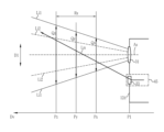
測長モードにおいて計測補助光を発光する場合、計測補助光の進行方向は、図6に示すように、計測補助光の光軸Lmが対物レンズの光軸Axと交差する状態で、かつ、計測補助光の光軸Lmが撮像光学系の撮影画角(2つの実線Li1で挟まれる領域内)に入る状態で、スポット状の計測補助光を出射する。観察距離の範囲Rxにおいて観察可能であるとすると、範囲Rxの近端Px、中央付近Py、及び遠端Pzでは、各点での撮像範囲(矢印Qx、Qy、Qzで示す)における計測補助光によって被写体上に形成されるスポットSPの位置(各矢印Qx、Qy、Qzが光軸Lmと交わる点)が異なることが分かる。内視鏡先端部12dの位置を位置P1とする。観察距離は、内視鏡先端部12dと被写体との距離である。したがって、観察距離は、それぞれ、位置P1と、近端Px、中央付近Py、又は遠端Pzとの間の距離である。観察距離は、詳細には、内視鏡先端部12dにおける撮像光学系44bの光軸Axの始点から被写体までの距離となる。軸Dvは観察距離を示す。なお、撮像光学系の撮影画角は2つの実線Li1で挟まれる領域内で表され、この撮影画角のうち収差の少ない中央領域(2つの点線Li2で挟まれる領域)で計測を行うようにしている。
When the measurement auxiliary light is emitted in the length measurement mode, the traveling direction of the measurement auxiliary light is such that the optical axis Lm of the measurement auxiliary light intersects the optical axis Ax of the objective lens, and Spot-shaped measurement auxiliary light is emitted in a state where the optical axis Lm of the auxiliary light falls within the imaging angle of view of the imaging optical system (within the area sandwiched between two solid lines Li1). Assuming that observation is possible in the observation distance range Rx, the measurement auxiliary light in the imaging range (indicated by arrows Qx, Qy, Qz) at each point at the near end Px, near the center Py, and far end Pz of the range Rx It can be seen that the positions of the spots SP formed on the subject (the points where the arrows Qx, Qy, and Qz intersect with the optical axis Lm) are different. The position of the
以上のように、撮像光学系の撮影画角に入る状態で、計測補助光を出射することによって、観察距離の変化に対するスポット位置の移動の感度が高いことから、被写体の大きさを高精度に計測することができる。計測補助光が照明された被写体を撮像素子46で撮像することによって、スポットSPを含む撮像画像が得られる。撮像画像では、スポットSPの位置は、撮像光学系44bの光軸Axと計測補助光の光軸Lmとの関係、及び観察距離に応じて異なるが、観察距離が近ければ、同一の実寸サイズ(例えば5mm)を示すピクセル数が多くなり、観察距離が遠ければピクセル数が少なくなる。したがって、スポットSPの位置と被写体の実寸サイズに対応する計測情報(ピクセル数)とを対応付けた対応情報(スケール用テーブル65、図8参照)を予め記憶しておくことで、スポットSPの位置から計測情報及び基準スケールを設定することができる。
As described above, by emitting the measurement auxiliary light when it is within the shooting field of view of the imaging optical system, the sensitivity of the spot position movement to changes in the observation distance is high, so the size of the subject can be determined with high precision. It can be measured. By capturing an image of the subject illuminated with the measurement auxiliary light using the
図7に示すように、プロセッサ装置14の信号処理部52は、通常信号処理部60、位置特定部61、基準スケール設定部62、計測値マーカ生成部63、及び特定画像生成部64とを備える。通常信号処理部60は、通常モードにおける撮像画像の処理を行う。位置特定部61は、基準スケールの設定等を行うために、撮像画像における被写体上のスポットSPの位置を特定する。基準スケール設定部62は、スポットSPの位置に基づいて被写体の実寸サイズを示す基準スケールを設定する。計測値マーカ生成部63は、設定された基準スケールに基づいて、注目領域の計測部分を計測した計測値を示す計測値マーカを生成する。
As shown in FIG. 7, the
注目領域とは、被写体に含まれるユーザーが注目すべき領域である。注目領域は、例えば、ポリープ等であり、計測が必要とされる可能性が高い領域である。また、計測部分とは、注目領域において、長さ等を計測する部分である。例えば、注目領域が発赤部である場合、計測部分は発赤部の最も長い部分等であり、また、注目領域が円形である場合、計測部分は注目領域の直径部分等である。 The attention area is an area included in the subject that the user should pay attention to. The region of interest is, for example, a polyp or the like, and is a region where measurement is likely to be required. Furthermore, the measurement portion is a portion in the region of interest where the length and the like are measured. For example, if the area of interest is a reddened area, the measurement part is the longest part of the reddened area, and if the area of interest is circular, the measurement part is the diameter part of the area of interest.
特定画像生成部64は、撮像画像に計測値マーカを重畳した特定画像を作成する。計測値マーカは、注目領域の計測部分に合わせた状態で撮像画像に重畳する。特定画像は、表示制御部53によってモニタ15に表示される。
The specific
測長モードに設定されている場合には、光源部41及び計測補助光出射部45は、照明光と計測補助光とを連続的に発光する。場合によっては、計測補助光は、点灯または減光して発光してもよい。なお、撮像画像は3色のRGB画像とするが、その他のカラー画像(輝度信号Y、色差信号Cr、Cb)であってもよい。したがって、信号処理部52には、測長モードに設定されている場合には、照明光および計測補助光により照明された被写体の撮像画像が入力される。撮像画像は、通信I/F51で取得される。
When set to the length measurement mode, the
通常モードに設定されている場合には、光源部41は、照明光を常時発する。照明光は、ライトガイド43を介して被写体に照射される。通常モードの場合には、計測補助光出射部45の光源45aは停止するので、計測補助光は消灯する。したがって、信号処理部52には、通常モードに設定されている場合には、照明光により照明された被写体の撮像画像が入力される。撮像画像は、通信I/F51で取得される。
When set to the normal mode, the
位置特定部61は、被写体上において計測補助光によって形成されるスポットSPの位置を特定する。スポットSPの位置の特定は、測長モードにて照明光および計測補助光により被写体を照明した撮像画像に基づいて行う。計測補助光によりスポットSPが形成された被写体の撮像画像は、撮像光学系及び撮像素子を介して取得される。
The
位置特定部61は、撮像画像のうち計測補助光の色に対応する成分を多く含む画像から認識することが好ましい。計測補助光は、例えば赤色の成分を多く含むことから、撮像画像のうち赤色画像からスポットSPの位置を認識することが好ましい。スポットSPの位置の認識方法は、例えば、撮像画像の赤色画像を二値化し、二値化画像のうち白部分(信号強度が二値化用閾値より高い画素)の重心を、スポットSPの位置として認識する方法がある。
It is preferable that the
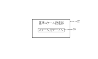
図8に示すように、基準スケール設定部62は、スケール用テーブル65を備える。スケール用テーブル65は、スポットSPの位置と被写体の実寸サイズに対応する計測情報とを対応付けた対応情報である。スケール用テーブル65の作成方法について具体的に説明すると、例えば、スポットSPの位置とマーカの大きさ(計測情報)との関係は、実寸サイズのパターンが規則的に形成されたチャートを撮像することで得ることができる。スポット状の計測補助光をチャートに向けて出射し、観察距離を変化させてスポットの位置を変えながら実寸サイズと同じ罫(5mm)もしくはそれより細かい罫(例えば1mm)の方眼紙状のチャートを撮像し、スポットの位置(撮像素子46の撮像面におけるピクセル座標)と実寸サイズに対応するピクセル数(実寸サイズである5mmが何ピクセルで表されるか)との関係を取得する。
As shown in FIG. 8, the reference
測長モードにおいて、照明光及び計測補助光により観察対象であるポリープ71を含む被写体が照明された撮像画像57が信号処理部52に入力される。図9に示すように、撮像画像57aにおいて、ポリープ71は、例えば、球が重なったような立体形状を有する。例えば、ポリープ71上の端部にスポットSPを形成する。撮像画像57aに基づき、位置特定部61は、スポットSPの位置を特定する。基準スケール設定部62は、スケール用テーブル65を参照して、特定したスポットSPの位置に対応した、被写体の実寸サイズを示す基準スケール72を設定する。
In the length measurement mode, a captured
基準スケール72は、例えば、実寸サイズにおける20mmに対応するピクセル数を有する線分並びに実寸サイズを示す数値及び単位である。基準スケール72は、通常はモニタ15に表示しないが、基準スケール72をモニタ15に表示する場合は、撮像画像57aのように撮像画像57に重畳してモニタ15に表示する。
The
図10に示すように、計測値マーカ生成部63は、注目領域抽出部74と、計測部分決定部75と、計測内容受付部76と、計測値算出部77とを備える。注目領域抽出部74は、画像処理技術又は画像認識技術等により注目領域を抽出する。注目領域は、例えば、ポリープ等の計測が必要とされる可能性が高い領域であるため、画像処理技術によれば、撮像画像上のエッジ部分を抽出すること等により注目領域を抽出することができ、また、画像認識技術によれば、機械学習による画像認識等により注目領域を抽出することができる。計測部分決定部75は、注目領域抽出部74が抽出した注目領域のどの部分を計測するかを決定する。計測部分決定部75は、予め設定した基準により選択した部分を計測部分としてもよいし、計測内容受付部76が受け付けた計測部分の指示に従って選択した部分を計測部分としてもよい。計測値算出部77は、基準スケール72及び計測部分に対応するピクセル数に基づいて、計測値マーカに対応するピクセル数を算出する。
As shown in FIG. 10, the measurement value
計測部分決定部75は、例えば、撮像画像57をモニタ15に表示した際の水平方向における注目領域のサイズを計測部分と決定する。図11に示すように、注目領域抽出部74は、撮像画像57bのように、斜線の領域を注目領域81として抽出する。次に、図12に示すように、計測部分決定部75は、例えば、予め設定した基準が、スポットSPを基点とした水平方向における注目領域の部分を計測するとの基準である場合、撮像画像57cのように、スポットSPを基点として、水平方向82と注目領域81のエッジとの交点である水平方向エッジ位置83を抽出する。スポットSPと水平方向エッジ位置83との間が計測部分となる。
The measurement
計測値算出部77は、例えば、基準マーカの実寸サイズをL0、撮像画像57に基準スケール72を重畳した場合の基準スケール72のピクセル数をAa、撮像画像57において注目領域81の計測部分に基準スケール72を重畳した場合の計測部分のピクセル数をBa、及び計測値マーカ84の実寸サイズをL1とした場合、以下の式(1)を満たすように計測値マーカを生成する。
For example, the measurement
L1=L0×Ba/Aa (1) L1=L0×Ba/Aa (1)
図13に示すように、計測値算出部77は、撮像画像57aに示す基準スケール72に対応するピクセル数Aaと、撮像画像57cに示すスポットSPと水平方向エッジ位置83との間の計測部分に対応するピクセル数Baとにより、例えば、Ba/Aaが0.7であった場合、基準スケール72の実寸サイズが20mmである際には、撮像画像57dのように、計測値マーカ84の実寸サイズを13mmと算出する。
As shown in FIG. 13, the measurement
特定画像生成部64は、撮像画像57に計測値マーカ84を重畳した特定画像58を作成する。例えば、図14に示すように、実寸サイズが算出した計測値マーカ84は、直線の線分の形状である矢印等の図形により撮像画像57に重畳する。特定画像生成部64は、撮像画像57に計測値マーカ84を注目領域81の計測部分に合わせた状態で重畳した特定画像58を作成する。計測値マーカ84は、計測値算出部77が算出した計測値マーカ84の実寸サイズの数値を含んでもよい。図15に示すように、計測値マーカ84の実寸サイズの数値は、矢印等の図形と離れた状態で撮像画像57に重畳して特定画像18としてもよい。
The specific
また、計測値マーカ84は、計測値の値を示す数字自体であってもよい。例えば、図16に示すように、計測部分のおおよその位置に、長さであるサイズの単位と計測値の値の数字とを、計測値マーカ84としてもよい。単位は、表示しなくてもよい。さらに、特定画像生成部64は、撮像画像57に、計測値マーカ84を、注目領域81の計測部分以外の部分に重畳した特定画像58を作成しても良い。例えば、図17に示すように、特定画像58の右下の部分に、計測部分がどこであるかの表示と計測値の値を示す数字とを計測値マーカ84として、「水平:13mm」のように重畳した特定画像58を作成しても良い。
Further, the
計測値マーカ84の種類は、予め設定することにより選択する。計測内容受付部76が計測値マーカ84の内容の設定を受け付けて計測値マーカ生成部63にその内容を送り、計測値マーカ生成部63がその内容に基づいて生成した計測値マーカ84を用いて、特定画像生成部64が特定画像58を作成する。
The type of
以上のように、内視鏡装置10は、ユーザーが内視鏡により観察を行う場合に、スポットSPを用いることにより、自動で測定対象である注目領域の計測が行われ、測定場所及び/又は測定値が実寸サイズとしてモニタ15に表示される。したがって、内視鏡装置10により、測定対象の計測が簡便に行うことができる。
As described above, when the user observes with an endoscope, the
なお、予め設定された固定サイズのスケールを有する計測値マーカと測定対象とを対比する場合は、図31(従来例)に示すように、計測値マーカの数値と測定対象のサイズとを、目視により対比することにより、測定対象の実寸サイズを推測して計測していた。内視鏡装置10によれば、測定対象の実寸サイズは自動で線分及び数値として表示することができる。したがって、内視鏡装置10によれば、作業手順が少なくなり、測定時間も短くなるため、測定対象の計測が簡便になることに加えて、測定精度も向上する。
In addition, when comparing a measurement value marker having a scale of a fixed size set in advance with a measurement target, as shown in FIG. 31 (conventional example), visually check the numerical value of the measurement value marker and the size of the measurement target. The actual size of the object to be measured was estimated and measured by comparing the two. According to the
なお、計測部分決定部75は、例えば、スポットSPが注目領域81上にある場合、スポットSPを基点とした際に、注目領域81において基点からのサイズが最大となる部分を計測部分と決定してもよい。図18に示すように、計測部分決定部75は、例えば、予め設定した基準が、スポットSPを基点とした際に、注目領域81において基点からのサイズが最大となる部分を計測するとの基準である場合、撮像画像57eのように、注目領域81において基点であるスポットSPからのサイズが最大となる部分である、延長方向86と注目領域81のエッジとの交点である延長方向エッジ位置87を抽出する。スポットSPと延長方向エッジ位置87との距離が計測部分となる。
Note that, for example, when the spot SP is on the region of
計測値算出部77は、上記式(1)と同様にして、計測部分のピクセル数をBb、及び計測値マーカ84の実寸サイズをL2とした場合、以下の式(2)を満たすように計測値マーカを生成する。
The measurement
L2=L0×Bb/Aa (2) L2=L0×Bb/Aa (2)
図19に示すように、計測値算出部77は、撮像画像57aに示す基準スケール72に対応するピクセル数Aaと、撮像画像57eに示すスポットSPと延長方向エッジ位置87との間に対応するピクセル数Bbとにより、例えば、Bb/Aaが0.8であった場合、基準スケール72の実寸サイズが20mmである際には、撮像画像57fのとおり、計測値マーカ84の実寸サイズを16mmと算出する。図20に示すように、算出後の計測値マーカ84は、線分並びに数値及び単位により表示して特定画像58とする。計測値マーカ84については、この他、上記した種類のように設定してもよい。
As shown in FIG. 19, the measurement
また、計測部分決定部75は、例えば、注目領域81の任意方向における最大サイズとなる部分を計測部分と決定してもよい。図21に示すように、計測部分決定部75は、例えば、予め設定した基準が、注目領域81の任意方向における最大サイズとなる部分を計測するとの基準である場合、撮像画像57gのように、注目領域81において距離が最大となる部分である最大方向88と注目領域81のエッジとの交点である最大方向エッジ位置89を抽出する。2つの最大方向エッジ位置89の距離が計測部分となる。
Furthermore, the measurement
計測値算出部77は、上記式(1)と同様にして、計測部分のピクセル数をBc、及び計測値マーカ84の実寸サイズをL3とした場合、以下の式(3)を満たすように計測値マーカを生成する。
The measurement
L3=L0×Bc/Aa (3) L3=L0×Bc/Aa (3)
図22に示すように、計測値算出部77は、撮像画像57aに示す基準スケール72に対応するピクセル数Aaと、撮像画像57gに示す2つの最大方向エッジ位置89のの間の計測部分に対応するピクセル数Bcとにより、例えば、Bc/Aaが1.0であった場合、基準スケール72の実寸サイズが20mmである際には、撮像画像57hのとおり、計測値マーカ84の実寸サイズを20mmと算出する。図23に示すように、算出後の計測値マーカ84は、線分並びに数値及び単位により表示して特定画像58とする。計測値マーカ84については、この他、上記した種類のように設定してもよい。
As shown in FIG. 22, the measurement
なお、上記したように、計測部分決定部75は、計測内容受付部76が受け付けた計測部分の指示に従って選択した部分を、計測部分として決定してもよい。例えば、計測内容受付部76は、注目領域81における水平方向エッジ位置83、延長方向エッジ位置87、又は最大方向エッジ位置89のいずれを選択するかの指示を受け付ける。
Note that, as described above, the measurement
計測内容受付部76は、例えば、スコープボタン12a、フットスイッチ17の左スイッチ17a、及び/又は右スイッチ17bとすることができる。1つのボタン又はスイッチを計測内容受付部76とした場合は、例えば、ボタン又はスイッチを押下(オン)する毎に、水平方向エッジ位置83、延長方向エッジ位置87、及び最大方向エッジ位置89が、この順に循環して選択され、特定画像58において、計測値マーカ84の表示が、この順に循環して切替わるようにしてもよい。また、ボタン又はスイッチの1つに1つの計測部分の指示を設定した場合は、例えば、スコープボタン12aを押下することにより、水平方向エッジ位置83が選択され、左スイッチ17aを押下することにより延長方向エッジ位置87が選択され、また右スイッチ17bを押下することにより最大方向エッジ位置89が選択され、特定画像58において、計測値マーカ84の表示も選択に従って自動で切り替わるようにしてもよい。
The measurement
なお、計測値マーカ生成部は、内視鏡が取得する撮像画像が有するひずみ分を考慮して、計測値マーカの生成を補正してもよい。図24に示すように、例えば、事前に撮像画像57における実寸サイズとひずみ情報を考慮したピクセル数とを対応させた補正スケール用テーブルを取得し、スケール用テーブル65に記憶しておく。計測値算出部77は、補正スケール用テーブルを用いて計測値マーカを生成する。
Note that the measurement value marker generation unit may correct the generation of the measurement value marker in consideration of the distortion that the captured image acquired by the endoscope has. As shown in FIG. 24, for example, a correction scale table in which the actual size of the captured
補正スケール用テーブルを用いる場合、基準スケールの実寸サイズをLr0、基準スケールについて撮像画像のひずみ情報により補正した補正ピクセル数をAr、計測部分について撮像画像のひずみ情報により補正した補正ピクセル数をBr、及び計測値マーカの実寸サイズをLr1とした場合、以下の式(4)を満たすように計測値マーカを生成する。 When using the correction scale table, the actual size of the reference scale is Lr0, the number of corrected pixels corrected for the reference scale based on the distortion information of the captured image is Ar, the number of corrected pixels corrected for the measurement part based on the distortion information of the captured image is Br, When the actual size of the measurement value marker is Lr1, the measurement value marker is generated so as to satisfy the following equation (4).
Lr1=Lr0×Br/Ar (4) Lr1=Lr0×Br/Ar (4)
図24に示すように、例えば、補正スケール用テーブル92は、実寸サイズのパターンが規則的に形成されたチャートを撮像することで得ることができる。スポット状の計測補助光をチャートに向けて出射し、観察距離を変化させてスポットの位置を変えながら実寸サイズと同じ罫(5mm)もしくはそれより細かい罫(例えば1mm)の方眼紙状のチャート91を撮像し、スポットの位置(撮像素子46の撮像面におけるピクセル座標)と実寸サイズに対応する補正ピクセル数(実寸サイズである5mmが何ピクセルで表されるか)との関係を補正スケール用テーブル92として取得する。例えば、基準スケール72の最大値20を補正ピクセル数の最大値Pに対応させ、基準スケール72の中間点10を補正ピクセル数の中間点0.5Pに対応させる。そして、図25に示すように、基準スケール72及び補正ピクセル数Ar及び補正ピクセル数Brを用いることにより、より精度が高い算出を行うことができる。補正ピクセル数を用いて計測部分の実寸サイズを算出することにより、例えば「14mm」と表示される。図26に示すように、算出後の計測値マーカ84は、線分並びに数値及び単位により表示して特定画像58とする。計測値マーカ84については、この他、上記した種類のように設定してもよい。
As shown in FIG. 24, for example, the correction scale table 92 can be obtained by imaging a chart in which patterns of actual size are regularly formed. A spot-shaped measurement auxiliary light is emitted toward the chart, and while changing the observation distance and changing the spot position, a graph paper-
撮像画像が有するひずみ分は、内視鏡によって異なる場合がある。したがって、より精度の高い計測を行うためには、内視鏡毎に補正スケール用テーブルを取得して保存したものを場合に応じて使用することが好ましい。 The amount of distortion that a captured image has may vary depending on the endoscope. Therefore, in order to perform more accurate measurements, it is preferable to obtain and save a correction scale table for each endoscope and use it depending on the situation.
なお、計測補助光は、被写体の立体的な形状を把握するため、平面状、メッシュ状、又はドット状であってもよい。この場合、特定領域は、形状がそれぞれ線状、メッシュ状、又はドット状である。 Note that the measurement auxiliary light may have a planar shape, a mesh shape, or a dot shape in order to grasp the three-dimensional shape of the subject. In this case, the specific area has a linear shape, a mesh shape, or a dot shape.
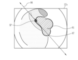
図27に示すように、例えば、計測補助光が平面状である場合は、平面状の計測補助光を出射することにより計測補助光により平面94が形成される。平面94は、内視鏡の視野95aに含まれるように計測補助光を出射する。平面状の計測補助光により、有効撮像範囲95bが形成される。計測補助光の出射位置と被写体との距離に応じて、撮像画像における位置が異なる状態で、被写体状にライン状の特定領域であるライン93が形成される。図27においては、右から計測補助光が出射されているため、計測補助光の出射位置と被写体との距離が離れるにつれて、断面96、97、又は98のように被写体状のライン93が形成される。したがって、被写体上において、ライン93が下から上へと移動する。このように、ライン状の計測補助光を用いても、上記したのと同様にして被写体のサイズを計測することができる。
As shown in FIG. 27, for example, when the measurement auxiliary light is planar, a
ライン状の計測補助光を用いた場合は、図28に示すように、特定画像58において、例えば、ポリープ71が立体的な形状を有し、ポリープ71の中心部が内視鏡先端部方向に盛り上がっている場合は、ライン93が、ポリープ71の立体形状により湾曲した形状となる。なお、目盛り99は、予め実寸サイズを目盛りとしたものとピクセル数との対応情報を取得し、スケール用テーブルに保存したものを用いて、表示制御部53が撮像画像に重畳したものである。したがって、この湾曲形状を有するライン上の計測補助光により、ポリープ71の例えば水平方向のサイズに加え、ポリープ71の奥行き(高さ)に関する情報を得ることができ、ポリープ71の高さを推測することができる。ポリープ71の高さを推測して計測する方法としては、上記したとおりの計測値マーカを作成したのと同様の方法とすることができる。このようにして、例えば、ポリープ71の水平方向のサイズを「13mm」とした計測値マーカ84と、ポリープ71の奥行きに関する情報を考慮したライン93の長さによるサイズを「16mm」とした計測値マーカ84とを生成し、撮像画像に重畳することにより特定画像58を生成する。なお、ポリープの奥行きの数値を高さとした計測値マーカ84としてもよい。
When a line-shaped measurement auxiliary light is used, as shown in FIG. 28, in the
なお、平面状の計測補助光の他、メッシュ状、ドット状、又は同心円状の計測補助光としてもよい。これらの計測補助光により、平面状の計測補助光と同様、奥行きがない場合の被写体における特定領域と、奥行きがある場合の被写体における特定領域との形状の違いを用いて、被写体が平面である場合のサイズに加え、被写体が奥行を持つ場合の奥行き情報も得られる。したがって、被写体の2次元方向のサイズに加え、奥行きのサイズも計測することができる。 In addition to the planar measurement auxiliary light, mesh-shaped, dot-shaped, or concentric measurement auxiliary light may be used. These measurement auxiliary lights, like flat measurement auxiliary lights, use the difference in shape between a specific area of the subject when there is no depth and a specific area of the subject when there is depth to determine whether the subject is flat. In addition to the size of the object, you can also obtain depth information if the object has depth. Therefore, in addition to the two-dimensional size of the subject, it is also possible to measure the depth size.
なお、注目領域抽出部は、過去に取得された撮像画像により学習した学習済みモデルを用いて注目領域を抽出することが好ましい。学習済みモデルに用いるモデルは、機械学習による画像認識において好適な各種のモデルを用いることができる。画像上の注目領域を認識する目的から、ニューラルネットワークを用いたモデルが好ましく使用できる。これらのモデルに対し学習させる場合は、教師データとして、注目領域の情報を持つ撮像画像を用いて学習させる。注目領域の情報としては、注目領域の有無、注目領域の位置又は範囲等が挙げられる。なお、モデルに応じて、注目領域の情報を持たない撮像画像により学習させてもよい。 Note that it is preferable that the region of interest extraction unit extracts the region of interest using a trained model learned from captured images acquired in the past. As the model used as the learned model, various models suitable for image recognition by machine learning can be used. For the purpose of recognizing a region of interest on an image, a model using a neural network can be preferably used. When training these models, the training is performed using captured images having information on the region of interest as training data. Information on the attention area includes the presence or absence of the attention area, the position or range of the attention area, and the like. Note that, depending on the model, learning may be performed using captured images that do not have information on the region of interest.
また、計測部分決定部も、過去に取得された撮像画像により学習した学習済みモデルを用いて計測部分を決定することが好ましい。学習済みモデルに用いるモデル等は、注目領域抽出部と同様であるが、これらのモデルに対し学習させる場合は、計測部分の情報を持つ撮像画像により学習させる。計測部分の情報としては、計測値とその計測部分が挙げられる。なお、モデルに応じて、計測部分の情報を持たない撮像画像により学習させてもよい。なお、注目領域抽出部が用いる学習済みモデルと、計測部分決定部が用いる学習済みモデルとは共通としてもよい。計測部分を抽出するとの目的の場合は、1つの学習済みモデルにより、撮像画像57から注目領域を抽出せずに、計測部分を抽出するようにしてもよい。
Further, it is preferable that the measurement portion determination unit also determines the measurement portion using a learned model learned from captured images acquired in the past. The models used for the trained model are the same as those used by the region of interest extraction unit, but when these models are to be trained, they are trained using captured images that have information on the measured portion. Information on the measurement portion includes a measurement value and its measurement portion. Note that, depending on the model, learning may be performed using captured images that do not have information on measurement portions. Note that the trained model used by the region of interest extraction unit and the trained model used by the measurement portion determination unit may be the same. If the purpose is to extract a measurement portion, the measurement portion may be extracted without extracting the region of interest from the captured
なお、注目領域抽出部74及び計測部分決定部75が用いる学習済みモデルは、注目領域及び計測部分をひとつ抽出することに加えて、注目領域及び計測部分を、候補として複数抽出してもよい。この場合、例えば、注目領域であれば、撮像画像57に複数の注目領域を重畳して表示した後、複数の注目領域から計測内容受付部76が受け付ける指示に従い、注目領域をひとつ抽出する。指示の方法としては、学習済みモデルが複数の注目領域を抽出し、等高線状に撮像画像57に重畳して表示する。そして、ユーザーがそれらの複数の注目領域のうち、計測を行いたい注目領域を示す等高線上にスポットSPを形成する。そして、信号処理部52は、スポットSPを認識することにより複数の注目領域候補からひとつの注目領域を抽出する。その後の流れは、上記したのと同様である。
Note that the trained model used by the region of
なお、特定画像と計測値とを対応付けた教師データを保存する教師データ保存部を備えることが好ましい。図29に示すように、画像保存部55は、静止画保存部101と、教師データ保存部102とを備える。特定画像生成部64は、生成した特定画像を、モニタ15に表示するために表示制御部53に送り、かつ、教師データとして教師データ保存部102に送り、教師データ保存部102は特定画像を教師データとして保存する。特定画像は、計測した部分及びその計測値といった計測部分の情報を有する画像情報であるため、例えば、撮像画像における計測値に関する機械学習における学習モデルの教師データとして有用である。
Note that it is preferable to include a teacher data storage unit that stores teacher data in which specific images and measurement values are associated with each other. As shown in FIG. 29, the
次に、上記構成による作用について、図30のフローチャートを参照して説明する。まず、通常モードにて被写体を観察する(ステップST110)。例えば、被写体に計測が必要な観察対象を見つけた場合等、スコープボタン12a等を用いて測長モードに移行する(ステップST120でYES)。測長モードに移行しない場合は(ステップST120でNO)、通常モードでの観察を続ける。
Next, the operation of the above configuration will be explained with reference to the flowchart of FIG. 30. First, a subject is observed in normal mode (step ST110). For example, when an observation target that requires measurement is found, the
測長モードに移行した場合は、測長モードにて観察を行う(ステップST130)。計測補助光出射部45が計測補助光を発光する(ステップST140)。計測補助光によるスポットSTは、ユーザーが計測部分の例えば計測の基点としたい場所である端部に位置させるようにして観察する(ステップST150)。撮像素子により、被写体を撮像した撮像画像を取得する(ステップST160)。撮像画像に基づき、位置特定部61が、スポットSTの位置を特定する(ステップST170)。
If the mode is shifted to the length measurement mode, observation is performed in the length measurement mode (step ST130). The measurement auxiliary
基準スケール設定部62は、得られた撮像画像及びスケール用テーブル65を用いて基準スケールを設定する(ステップST180)。計測部分の指定、計測値マーカの種類の指定がある場合は(ステップST190でYES)、水平方向等の計測部分の指定を行い、表示したい計測値マーカの種類の指定がある場合は指定し、計測内容受付部76がこれらの指定を受け付ける(ステップST200)。なお、計測部分の指定等がない場合は(ステップST190でNO)、直前の観察において用いられた計測部分及び計測値マーカが自動的に適用となる。その後計測値マーカを生成し(ステップST210)、撮像画像57に重畳して特定画像58が作成される(ステップST220)。作成された特定画像58は、モニタ15に表示され、また、画像保存部55の教師データ保存部102に保存される(ステップST230)。
The reference
以上の観察の流れにおいて、ユーザーは、特に指定がない場合は、スポットSPを計測の基点としたい場所に位置させるのみで、注目領域の特定の測定部分の測定値を数値にて得ることができる。したがって、図31に示すように、従来、計測値マーカとの対比を目視等で行うことにより計測したい部分の計測値を得ていたのと比べて、必要な作業が減る。なお、従来では、ポリープ71のスポットSPから水平方向のサイズを計測する場合、例えば、マーカーの20mmの数値に、B/Aの長さの比の値を推定等してかけることにより計測していた。ここで、Aは基準スケールの長さであり、Bはポリープの水平方向のサイズ(長さ)である。
In the above observation flow, unless otherwise specified, the user can obtain the numerical value of a specific measurement part of the region of interest by simply positioning the spot SP at the location where the user wants to use the measurement base point. . Therefore, as shown in FIG. 31, the required work is reduced compared to the conventional method of obtaining the measured value of the part to be measured by visually comparing with the measured value marker. Conventionally, when measuring the size in the horizontal direction from the spot SP of the
また、測定値を得るのに必要な時間が大幅に減るため、被写体の動き等の影響も減り、計測値の精度及び速度が向上する。また、領域の抽出及び/又は計測部分の抽出は、学習済みモデルを使用することができるため、注目領域の抽出又は計測値の算出において、精度が向上する。また、計測値マーカの表示は設定により変更することができるため、内視鏡による観察の邪魔にならないようにすることができる。また、計測値マーカの形状は、線分のような図形の他、数値自体とすることができるため、この数値データも、撮像画像の情報として保存することにより、患者データ又は教師データ等各種の目的に利用することができる。また、ラインレーザー等計測補助光の形状を工夫することにより、ポリープ等の注目領域の奥行方向の情報を得ることができる。また、内視鏡装置10によれば、管腔または血管等の狭窄の情報を得ることができるため、例えば、ステントの径を決定する場合またはバルーンを適用する場合等に好適である。この場合も、ラインレーザー等計測補助光の形状を工夫することにより、奥行方向の情報を得ることができるため好ましい。また、以上の流れは自動で行うことができる。以上のとおり、内視鏡装置10によれば、測定対象の計測を簡便に行うことができる。
Furthermore, since the time required to obtain a measured value is significantly reduced, the influence of the movement of the subject is also reduced, and the accuracy and speed of the measured value are improved. Further, since a trained model can be used to extract a region and/or a measurement portion, accuracy is improved in extracting a region of interest or calculating a measurement value. Furthermore, since the display of the measurement value marker can be changed by setting, it can be prevented from interfering with observation using an endoscope. In addition, since the shape of the measurement value marker can be a figure such as a line segment or a numerical value itself, this numerical data can also be saved as information of the captured image, and can be used to store various types of patient data, teacher data, etc. It can be used for any purpose. Further, by devising the shape of the measurement auxiliary light such as a line laser, it is possible to obtain information in the depth direction of a region of interest such as a polyp. Further, the
上記実施形態において、信号処理部52、表示制御部53、システム制御部54、又は画像保存部55といった各種の処理を実行する処理部(processing unit)のハードウェア的な構造は、次に示すような各種のプロセッサ(processor)である。各種のプロセッサには、ソフトウエア(プログラム)を実行して各種の処理部として機能する汎用的なプロセッサであるCPU(Central Processing Unit)、FPGA (Field Programmable Gate Array) などの製造後に回路構成を変更可能なプロセッサであるプログラマブルロジックデバイス(Programmable Logic Device:PLD)、ASIC(Application Specific Integrated Circuit)などの特定の処理を実行させるために専用に設計された回路構成を有するプロセッサである専用電気回路などが含まれる。
In the above embodiment, the hardware structure of a processing unit that executes various processes such as the
1つの処理部は、これら各種のプロセッサのうちの1つで構成されてもよいし、同種または異種の2つ以上のプロセッサの組み合せ(例えば、複数のFPGAや、CPUとFPGAの組み合わせ)で構成されてもよい。また、複数の処理部を1つのプロセッサで構成してもよい。複数の処理部を1つのプロセッサで構成する例としては、第1に、クライアントやサーバなどのコンピュータに代表されるように、1つ以上のCPUとソフトウエアの組み合わせで1つのプロセッサを構成し、このプロセッサが複数の処理部として機能する形態がある。第2に、システムオンチップ(System On Chip:SoC)などに代表されるように、複数の処理部を含むシステム全体の機能を1つのIC(Integrated Circuit)チップで実現するプロセッサを使用する形態がある。このように、各種の処理部は、ハードウェア的な構造として、上記各種のプロセッサを1つ以上用いて構成される。 One processing unit may be composed of one of these various types of processors, or may be composed of a combination of two or more processors of the same type or different types (for example, multiple FPGAs or a combination of a CPU and an FPGA). may be done. Further, the plurality of processing units may be configured with one processor. As an example of configuring multiple processing units with one processor, first, as typified by computers such as clients and servers, one processor is configured with a combination of one or more CPUs and software, There is a form in which this processor functions as a plurality of processing units. Second, there are processors that use a single IC (Integrated Circuit) chip to implement the functions of an entire system including multiple processing units, as typified by System On Chip (SoC). be. In this way, various processing units are configured using one or more of the various processors described above as a hardware structure.
さらに、これらの各種のプロセッサのハードウェア的な構造は、より具体的には、半導体素子などの回路素子を組み合わせた形態の電気回路(circuitry)である。 Furthermore, the hardware structure of these various processors is, more specifically, an electric circuit (circuitry) in the form of a combination of circuit elements such as semiconductor elements.
本発明の他の態様は、被写体の計測に用いる計測補助光を発する計測補助光光源部と、プロセッサと、を備え、プロセッサは、計測補助光によって被写体上に形成される特定領域を含む被写体を撮像した撮像画像を取得し、撮像画像において被写体上の特定領域の位置を特定し、特定領域の位置に基づいて被写体の実寸サイズを示す基準スケールを設定し、撮像画像において被写体が含む注目領域を抽出し、注目領域においてサイズを計測する計測部分を決定し、基準スケールに基づいて注目領域の計測部分を計測した計測値を示す計測値マーカを生成し、撮像画像に計測値マーカを重畳した特定画像を作成する内視鏡装置である。 Another aspect of the present invention includes a measurement auxiliary light source unit that emits measurement auxiliary light used for measuring an object, and a processor, the processor detecting the object including a specific area formed on the object by the measurement auxiliary light. Obtain the captured image, identify the position of a specific area on the subject in the captured image, set a reference scale that indicates the actual size of the subject based on the position of the specific area, and determine the area of interest that the subject includes in the captured image. Extract and determine the measurement part whose size is to be measured in the attention area, generate a measurement value marker indicating the measurement value of the measurement part of the attention area based on the reference scale, and superimpose the measurement value marker on the captured image. This is an endoscope device that creates images.
本発明は、上記実施形態に限らず、本発明の要旨を逸脱しない限り種々の構成を採用し得ることはもちろんである。さらに、本発明は、プログラムに加えて、プログラムを記憶する記憶媒体にもおよぶ。 It goes without saying that the present invention is not limited to the embodiments described above, and that various configurations can be adopted as long as they do not depart from the gist of the present invention. Furthermore, the present invention extends not only to the program but also to a storage medium that stores the program.
10 内視鏡装置
12 内視鏡
12a スコープボタン
12d 先端部
13 光源装置
13a 光源ボタン
14 プロセッサ装置
14a プロセッサボタン
15 モニタ
16 キーボード
17 フットスイッチ
17a 左スイッチ
17b 右スイッチ
21 挿入部
22 操作部
23 ユニバーサルケーブル
25 コネクタ
31 対物レンズ
32 照明レンズ
33 計測補助光用レンズ
34 開口
35 送気送水ノズル
41 光源部
42 光源制御部
43 ライトガイド
44a 照明光学系
44b 撮像光学系
45 計測補助光出射部
45a 光源
45b 計測補助光生成素子
45c プリズム
46 撮像素子
47 撮像制御部
48 CDS/AGC回路
49 A/D変換器
50、51 通信I/F
52 信号処理部
53 表示制御部
54 システム制御部
55 画像保存部
57、57a~57h 撮像画像
58 特定画像
60 通常信号処理部
61 位置特定部
62 基準スケール設定部
63 計測値マーカ生成部
64 特定画像生成部
65 スケール用テーブル
71 ポリープ
72 基準スケール
74 注目領域抽出部
75 計測部分決定部
76 計測内容受付部
77 計測値算出部
81 注目領域
82 水平方向
83 水平方向エッジ位置
84 計測値マーカ
86 延長方向
87 延長方向エッジ位置
88 最大方向
89 最大方向エッジ位置
91 チャート
92 補正スケール用テーブル
93 ライン
94 平面
95a 視野
95b 有効撮像範囲
96、97、98 断面
99 目盛り
101 静止画保存部
102 教師データ保存部
A 基準スケールの長さ
Aa 基準スケールのピクセル数
B ポリープの水平方向のサイズ
Ba、Bb、Bc 計測部分のピクセル数
Ar、Br 補正ピクセル数
Li1 実線
Li2 点線
D1 第1方向
D2 第2方向
Dv 観察距離
Lm 計測補助光の光軸
Ax 撮像光学系の光軸
Px 近端
Py 中央付近
Pz 遠端
P1 位置
Qx、Qy、Qz 撮影範囲
Rx 観察距離の範囲
SP スポット
ST110~ST230 ステップ
10
52 Signal processing section 53
Claims (22)
プロセッサとを備え、
前記プロセッサは、
前記計測補助光によって前記被写体上に形成される特定領域を含む前記被写体を撮像した撮像画像を取得し、
前記撮像画像において前記被写体上の前記特定領域の位置を特定し、
前記特定領域の位置に基づいて前記被写体の実寸サイズを示す基準スケールを設定し、
前記撮像画像において前記被写体が含む注目領域を抽出し、
前記注目領域においてサイズを計測する計測部分を、予め設定した基準により選択した部分を前記計測部分とするか、または、前記計測部分の指定を受け付け、前記指定に従って選択した部分を前記計測部分とするかのいずれかに基づき決定し、
前記基準スケールに基づいて前記注目領域の前記計測部分を計測した計測値を示す計測値マーカを生成し、
前記撮像画像に前記計測値マーカを重畳した特定画像を作成する内視鏡装置。 a measurement auxiliary light source unit that emits measurement auxiliary light used for measuring a subject;
Equipped with a processor,
The processor includes:
obtaining a captured image of the subject including a specific area formed on the subject by the measurement auxiliary light;
identifying the position of the specific area on the subject in the captured image;
setting a reference scale indicating the actual size of the subject based on the position of the specific area;
extracting a region of interest included in the subject in the captured image;
A part whose size is to be measured in the region of interest is selected based on preset criteria, or a designation of the measurement part is accepted, and a part selected according to the designation is set as the measurement part. Determine based on either of the following :
generating a measurement value marker indicating a measurement value obtained by measuring the measurement portion of the region of interest based on the reference scale;
An endoscope device that creates a specific image in which the measurement value marker is superimposed on the captured image.
プロセッサとを備え、
前記プロセッサは、
前記計測補助光によって前記被写体上に形成される特定領域を含む前記被写体を撮像した撮像画像を取得し、
前記撮像画像において前記被写体上の前記特定領域の位置を特定し、
前記特定領域の位置に基づいて前記被写体の実寸サイズを示す基準スケールを設定し、
前記撮像画像において前記被写体が含む注目領域を抽出し、
前記注目領域においてサイズを計測する計測部分を決定し、
前記基準スケールに基づいて前記注目領域の前記計測部分を計測した計測値を示す計測値マーカを生成し、
前記撮像画像に前記計測値マーカを重畳した特定画像を作成し、
前記特定領域が前記注目領域上にある場合、前記特定領域を起点とした際に、前記注目領域において前記起点からのサイズが最大となる部分を前記計測部分と決定する内視鏡装置。 a measurement auxiliary light source unit that emits measurement auxiliary light used for measuring a subject;
Equipped with a processor,
The processor includes:
obtaining a captured image of the subject including a specific area formed on the subject by the measurement auxiliary light;
identifying the position of the specific area on the subject in the captured image;
setting a reference scale indicating the actual size of the subject based on the position of the specific area;
extracting a region of interest included in the subject in the captured image;
determining a measurement portion for measuring the size in the region of interest;
generating a measurement value marker indicating a measurement value obtained by measuring the measurement portion of the region of interest based on the reference scale;
creating a specific image in which the measurement value marker is superimposed on the captured image ;
When the specific region is on the region of interest, the endoscopic device determines, when the specific region is used as a starting point, a portion of the region of interest that has a maximum size from the starting point as the measurement portion .
プロセッサとを備え、
前記プロセッサは、
前記計測補助光によって前記被写体上に形成される特定領域を含む前記被写体を撮像した撮像画像を取得し、
前記撮像画像において前記被写体上の前記特定領域の位置を特定し、
前記特定領域の位置に基づいて前記被写体の実寸サイズを示す基準スケールを設定し、
前記撮像画像において前記被写体が含む注目領域を抽出し、
前記注目領域においてサイズを計測する計測部分を決定し、
前記基準スケールに基づいて前記注目領域の前記計測部分を計測した計測値を示す計測値マーカを生成し、
前記撮像画像に前記計測値マーカを重畳した特定画像を作成し、
前記基準スケールの前記実寸サイズをL0、前記撮像画像に前記基準スケールを重畳した場合の前記基準スケールのピクセル数をAa、前記撮像画像において前記注目領域の前記計測部分に前記基準スケールを重畳した場合の計測部分のピクセル数をBa、及び前記計測値マーカの前記実寸サイズをL1とした場合、以下の式(1)を満たすように前記計測値マーカを生成する内視鏡装置。
L1=L0×Ba/Aa (1) a measurement auxiliary light source unit that emits measurement auxiliary light used for measuring a subject;
Equipped with a processor,
The processor includes:
obtaining a captured image of the subject including a specific area formed on the subject by the measurement auxiliary light;
identifying the position of the specific area on the subject in the captured image;
setting a reference scale indicating the actual size of the subject based on the position of the specific area;
extracting a region of interest included in the subject in the captured image;
determining a measurement portion for measuring the size in the region of interest;
generating a measurement value marker indicating a measurement value obtained by measuring the measurement portion of the region of interest based on the reference scale;
creating a specific image in which the measurement value marker is superimposed on the captured image ;
The actual size of the reference scale is L0, the number of pixels of the reference scale when the reference scale is superimposed on the captured image is Aa, and the reference scale is superimposed on the measurement portion of the region of interest in the captured image. An endoscope device that generates the measurement value marker so as to satisfy the following formula (1), where Ba is the number of pixels of the measurement portion of the measurement portion, and L1 is the actual size of the measurement value marker.
L1=L0×Ba/Aa (1)
プロセッサとを備え、
前記プロセッサは、
前記計測補助光によって前記被写体上に形成される特定領域を含む前記被写体を撮像した撮像画像を取得し、
前記撮像画像において前記被写体上の前記特定領域の位置を特定し、
前記特定領域の位置に基づいて前記被写体の実寸サイズを示す基準スケールを設定し、
前記撮像画像において前記被写体が含む注目領域を抽出し、
前記注目領域においてサイズを計測する計測部分を決定し、
前記基準スケールに基づいて前記注目領域の前記計測部分を計測した計測値を示す計測値マーカを生成し、
前記撮像画像に前記計測値マーカを重畳した特定画像を作成し、
前記基準スケールの前記実寸サイズをL0、前記撮像画像に前記基準スケールを重畳し、かつ、前記撮像画像のひずみ情報を考慮して補正した場合の前記基準スケールのピクセル数をAc、前記撮像画像において前記注目領域の前記計測部分に前記基準スケールを重畳し、かつ、前記撮像画像のひずみ情報を考慮して補正した場合の前記計測部分のピクセル数をBc、及び前記計測値マーカの前記実寸サイズをL1とした場合、以下の式(2)を満たすように前記計測値マーカを生成する内視鏡装置。
L1=L0×Bc/Ac (2) a measurement auxiliary light source unit that emits measurement auxiliary light used for measuring a subject;
Equipped with a processor,
The processor includes:
obtaining a captured image of the subject including a specific area formed on the subject by the measurement auxiliary light;
identifying the position of the specific area on the subject in the captured image;
setting a reference scale indicating the actual size of the subject based on the position of the specific area;
extracting a region of interest included in the subject in the captured image;
determining a measurement portion for measuring the size in the region of interest;
generating a measurement value marker indicating a measurement value obtained by measuring the measurement portion of the region of interest based on the reference scale;
creating a specific image in which the measurement value marker is superimposed on the captured image ;
The actual size of the reference scale is L0, the number of pixels of the reference scale when the reference scale is superimposed on the captured image and corrected in consideration of distortion information of the captured image is Ac, in the captured image. Bc is the number of pixels of the measurement portion when the reference scale is superimposed on the measurement portion of the region of interest and is corrected by taking into account distortion information of the captured image, and Bc is the actual size of the measurement value marker. L1, an endoscope apparatus that generates the measurement value marker so as to satisfy the following equation (2) .
L1=L0×Bc/Ac (2)
プロセッサとを備え、
前記プロセッサは、
前記計測補助光によって前記被写体上に形成される特定領域を含む前記被写体を撮像した撮像画像を取得し、
前記撮像画像において前記被写体上の前記特定領域の位置を特定し、
前記特定領域の位置に基づいて前記被写体の実寸サイズを示す基準スケールを設定し、
前記撮像画像において前記被写体が含む注目領域を抽出し、
前記注目領域においてサイズを計測する計測部分を決定し、
前記基準スケールに基づいて前記注目領域の前記計測部分を計測した計測値を示す計測値マーカを生成し、
前記撮像画像に前記計測値マーカを重畳した特定画像を作成し、
前記特定画像と前記計測値とを対応付けた教師データを保存する内視鏡装置。 a measurement auxiliary light source unit that emits measurement auxiliary light used for measuring a subject;
Equipped with a processor,
The processor includes:
obtaining a captured image of the subject including a specific area formed on the subject by the measurement auxiliary light;
identifying the position of the specific area on the subject in the captured image;
setting a reference scale indicating the actual size of the subject based on the position of the specific area;
extracting a region of interest included in the subject in the captured image;
determining a measurement portion for measuring the size in the region of interest;
generating a measurement value marker indicating a measurement value obtained by measuring the measurement portion of the region of interest based on the reference scale;
creating a specific image in which the measurement value marker is superimposed on the captured image ;
An endoscope device that stores training data in which the specific image and the measured value are associated with each other .
前記指定に従って前記計測部分を決定する請求項3ないし5のいずれか1項に記載の内視鏡装置。 the processor accepts the designation of the measurement portion;
The endoscope apparatus according to any one of claims 3 to 5, wherein the measurement portion is determined according to the designation.
L1=L0×Ba/Aa (1) The processor sets the actual size of the reference scale to L0, the number of pixels of the reference scale when the reference scale is superimposed on the captured image to Aa, and the reference scale to the measurement portion of the region of interest in the captured image. 2. The measurement value marker is generated so as to satisfy the following formula (1), where Ba is the number of pixels of the measurement portion when superimposed, and L1 is the actual size of the measurement value marker. The endoscopic device described in .
L1=L0×Ba/Aa (1)
L1=L0×Bc/Ac (2) The processor sets the actual size of the reference scale to L0, the number of pixels of the reference scale when superimposing the reference scale on the captured image and correcting it by taking into account distortion information of the captured image, Ac, Bc is the number of pixels in the measurement portion when the reference scale is superimposed on the measurement portion of the region of interest in the captured image and correction is performed taking into account distortion information of the captured image, and Bc is the number of pixels in the measurement portion of the measurement value marker. The endoscope apparatus according to claim 1 or 2 , wherein when the actual size is L1, the measurement value marker is generated so as to satisfy the following equation (2).
L1=L0×Bc/Ac (2)
前記特定領域は、形状がそれぞれ線状、メッシュ状、又はドット状である請求項1ないし11のいずれか1項に記載の内視鏡装置。 The measurement auxiliary light has a planar shape, a mesh shape, or a dot shape,
The endoscope apparatus according to any one of claims 1 to 11 , wherein each of the specific regions has a linear shape, a mesh shape, or a dot shape.
前記計測補助光によって前記被写体上に形成される特定領域を含む前記被写体を撮像した撮像画像を取得する撮像画像取得ステップと、
前記撮像画像において前記被写体上の前記特定領域の位置を特定する位置特定ステップと、
前記特定領域の位置に基づいて前記被写体の実寸サイズを示す基準スケールを設定する基準スケール設定ステップと、
前記撮像画像において前記被写体が含む注目領域を抽出する注目領域抽出ステップと、
前記注目領域においてサイズを計測する計測部分を、予め設定した基準により選択した部分を前記計測部分とするか、または、前記計測部分の指定を受け付け、前記指定に従って選択した部分を前記計測部分とするかのいずれかに基づき決定する計測部決定ステップと、
前記基準スケールに基づいて前記注目領域の前記計測部分を計測した計測値を示す計測値マーカを生成する計測値マーカ生成ステップと、
前記撮像画像に前記計測値マーカを重畳した特定画像を作成する特定画像生成ステップとを備える内視鏡装置の作動方法。 a measurement auxiliary light emitting step that emits a measurement auxiliary light used for measuring a subject;
a captured image acquisition step of acquiring a captured image of the subject including a specific area formed on the subject by the measurement auxiliary light;
a position specifying step of specifying the position of the specific area on the subject in the captured image;
a reference scale setting step of setting a reference scale indicating the actual size of the subject based on the position of the specific area;
an attention area extraction step of extracting an attention area included in the subject in the captured image;
A part whose size is to be measured in the region of interest is selected based on preset criteria, or a designation of the measurement part is accepted, and a part selected according to the designation is set as the measurement part. a measurement unit determination step, which is determined based on either of the following ;
a measurement value marker generation step of generating a measurement value marker indicating a measurement value obtained by measuring the measurement portion of the region of interest based on the reference scale;
A method for operating an endoscope apparatus, comprising a specific image generation step of creating a specific image in which the measurement value marker is superimposed on the captured image.
コンピュータに、
被写体の計測に用いる計測補助光を発する機能と、
前記計測補助光によって前記被写体上に形成される特定領域を含む前記被写体を撮像した撮像画像を取得する機能と、
前記撮像画像において前記被写体上の前記特定領域の位置を特定する機能と、
前記特定領域の位置に基づいて前記被写体の実寸サイズを示す基準スケールを設定する機能と、
前記撮像画像において前記被写体が含む注目領域を抽出する機能と、
前記注目領域においてサイズを計測する計測部分を予め設定した基準により選択した部分を前記計測部分とするか、または、前記計測部分の指定を受け付け、前記指定に従って選択した部分を前記計測部分とするかのいずれかに基づき決定する機能と、
前記基準スケールに基づいて前記注目領域の前記計測部分を計測した計測値を示す計測値マーカを生成する機能と、
前記撮像画像に前記計測値マーカを重畳した特定画像を作成する機能とを実現させるための内視鏡装置用プログラム。 A program for an endoscope device comprising a measurement auxiliary light source unit that emits measurement auxiliary light used for measuring a subject,
to the computer,
A function that emits a measurement auxiliary light used for measuring the subject,
a function of acquiring a captured image of the subject including a specific area formed on the subject by the measurement auxiliary light;
a function of specifying the position of the specific area on the subject in the captured image;
a function of setting a reference scale indicating the actual size of the subject based on the position of the specific area;
a function of extracting a region of interest included in the subject in the captured image;
A measurement portion whose size is to be measured in the region of interest is selected based on a preset standard, or a designation of the measurement portion is accepted and a portion selected according to the designation is used as the measurement portion. a function to decide based on either ;
a function of generating a measurement value marker indicating a measurement value obtained by measuring the measurement portion of the region of interest based on the reference scale;
A program for an endoscope apparatus for realizing a function of creating a specific image in which the measurement value marker is superimposed on the captured image.
Applications Claiming Priority (3)
| Application Number | Priority Date | Filing Date | Title |
|---|---|---|---|
| JP2019234984 | 2019-12-25 | ||
| JP2019234984 | 2019-12-25 | ||
| PCT/JP2020/038509 WO2021131238A1 (en) | 2019-12-25 | 2020-10-12 | Endoscope device, operation method thereof, and program for endoscope device |
Publications (3)
| Publication Number | Publication Date |
|---|---|
| JPWO2021131238A1 JPWO2021131238A1 (en) | 2021-07-01 |
| JPWO2021131238A5 JPWO2021131238A5 (en) | 2022-07-27 |
| JP7402252B2 true JP7402252B2 (en) | 2023-12-20 |
Family
ID=76574210
Family Applications (1)
| Application Number | Title | Priority Date | Filing Date |
|---|---|---|---|
| JP2021566837A Active JP7402252B2 (en) | 2019-12-25 | 2020-10-12 | Endoscope device, its operating method, and program for endoscope device |
Country Status (4)
| Country | Link |
|---|---|
| US (1) | US20220330850A1 (en) |
| EP (1) | EP4083677A4 (en) |
| JP (1) | JP7402252B2 (en) |
| WO (1) | WO2021131238A1 (en) |
Families Citing this family (1)
| Publication number | Priority date | Publication date | Assignee | Title |
|---|---|---|---|---|
| JP2023112340A (en) | 2022-02-01 | 2023-08-14 | 富士フイルム株式会社 | Endoscope system and operation method thereof |
Citations (6)
| Publication number | Priority date | Publication date | Assignee | Title |
|---|---|---|---|---|
| JP2008061659A (en) | 2006-09-04 | 2008-03-21 | National Univ Corp Shizuoka Univ | Imaging device |
| US20090097725A1 (en) | 2007-10-15 | 2009-04-16 | Hagai Krupnik | Device, system and method for estimating the size of an object in a body lumen |
| JP2017520355A (en) | 2014-05-20 | 2017-07-27 | パク, ヒュン・ジュンPark, Hyun Jun | Method for measuring size of lesion in endoscopy and computer-readable recording medium |
| WO2018189742A1 (en) | 2017-04-13 | 2018-10-18 | V.T.M. (Virtual Tape Measure) Technologies Ltd. | Endoscopic measurement methods and tools |
| WO2019017019A1 (en) | 2017-07-18 | 2019-01-24 | 富士フイルム株式会社 | Endoscope device and measurement assistance method |
| JP2019195643A (en) | 2019-06-26 | 2019-11-14 | 富士フイルム株式会社 | Endoscope system |
Family Cites Families (3)
| Publication number | Priority date | Publication date | Assignee | Title |
|---|---|---|---|---|
| JPS6273223A (en) * | 1985-09-26 | 1987-04-03 | Toshiba Corp | Endoscope device |
| JP6692440B2 (en) | 2016-09-15 | 2020-05-13 | 富士フイルム株式会社 | Endoscope system |
| JP6964592B2 (en) * | 2016-09-15 | 2021-11-10 | 富士フイルム株式会社 | Measurement support device, endoscope system, endoscope system processor, and measurement support method |
-
2020
- 2020-10-12 JP JP2021566837A patent/JP7402252B2/en active Active
- 2020-10-12 EP EP20904910.5A patent/EP4083677A4/en active Pending
- 2020-10-12 WO PCT/JP2020/038509 patent/WO2021131238A1/en unknown
-
2022
- 2022-06-24 US US17/808,727 patent/US20220330850A1/en active Pending
Patent Citations (6)
| Publication number | Priority date | Publication date | Assignee | Title |
|---|---|---|---|---|
| JP2008061659A (en) | 2006-09-04 | 2008-03-21 | National Univ Corp Shizuoka Univ | Imaging device |
| US20090097725A1 (en) | 2007-10-15 | 2009-04-16 | Hagai Krupnik | Device, system and method for estimating the size of an object in a body lumen |
| JP2017520355A (en) | 2014-05-20 | 2017-07-27 | パク, ヒュン・ジュンPark, Hyun Jun | Method for measuring size of lesion in endoscopy and computer-readable recording medium |
| WO2018189742A1 (en) | 2017-04-13 | 2018-10-18 | V.T.M. (Virtual Tape Measure) Technologies Ltd. | Endoscopic measurement methods and tools |
| WO2019017019A1 (en) | 2017-07-18 | 2019-01-24 | 富士フイルム株式会社 | Endoscope device and measurement assistance method |
| JP2019195643A (en) | 2019-06-26 | 2019-11-14 | 富士フイルム株式会社 | Endoscope system |
Also Published As
| Publication number | Publication date |
|---|---|
| US20220330850A1 (en) | 2022-10-20 |
| WO2021131238A1 (en) | 2021-07-01 |
| JPWO2021131238A1 (en) | 2021-07-01 |
| EP4083677A1 (en) | 2022-11-02 |
| EP4083677A4 (en) | 2023-02-01 |
Similar Documents
| Publication | Publication Date | Title |
|---|---|---|
| US20190204069A1 (en) | Endoscope system | |
| US7123756B2 (en) | Method and apparatus for standardized fluorescence image generation | |
| US11419694B2 (en) | Endoscope system measuring size of subject using measurement auxiliary light | |
| JP7115897B2 (en) | endoscope device | |
| US11490785B2 (en) | Measurement support device, endoscope system, and processor measuring size of subject using measurement auxiliary light | |
| JP7402252B2 (en) | Endoscope device, its operating method, and program for endoscope device | |
| US20200260932A1 (en) | Endoscope apparatus | |
| EP3705023B1 (en) | Endoscope apparatus, calibration device, and calibration method | |
| JP7029359B2 (en) | Endoscope device and its operation method as well as programs for endoscope devices | |
| JP6924727B2 (en) | Endoscope device | |
| WO2020189334A1 (en) | Endoscope processor device, medical image processing device, operation method thereof, and program for medical image processing device | |
| JP7166467B2 (en) | ENDOSCOPE DEVICE, OPERATION METHOD THEREOF, AND PROGRAM FOR ENDOSCOPE DEVICE | |
| JP7167352B2 (en) | Endoscope system and its operating method | |
| WO2020153186A1 (en) | Endoscope device | |
| US11399707B2 (en) | Endoscope apparatus | |
| US20230240511A1 (en) | Endoscope system and endoscope system operation method | |
| JP2020151250A (en) | Endoscope apparatus and operation method therefor, and program for endoscope apparatus | |
| JPH01209415A (en) | Endoscope device with measuring function |
Legal Events
| Date | Code | Title | Description |
|---|---|---|---|
| A621 | Written request for application examination |
Free format text: JAPANESE INTERMEDIATE CODE: A621 Effective date: 20220530 |
|
| A521 | Request for written amendment filed |
Free format text: JAPANESE INTERMEDIATE CODE: A523 Effective date: 20220707 |
|
| A131 | Notification of reasons for refusal |
Free format text: JAPANESE INTERMEDIATE CODE: A131 Effective date: 20230523 |
|
| A601 | Written request for extension of time |
Free format text: JAPANESE INTERMEDIATE CODE: A601 Effective date: 20230721 |
|
| A521 | Request for written amendment filed |
Free format text: JAPANESE INTERMEDIATE CODE: A523 Effective date: 20230915 |
|
| TRDD | Decision of grant or rejection written | ||
| A01 | Written decision to grant a patent or to grant a registration (utility model) |
Free format text: JAPANESE INTERMEDIATE CODE: A01 Effective date: 20231205 |
|
| A61 | First payment of annual fees (during grant procedure) |
Free format text: JAPANESE INTERMEDIATE CODE: A61 Effective date: 20231208 |
|
| R150 | Certificate of patent or registration of utility model |
Ref document number: 7402252 Country of ref document: JP Free format text: JAPANESE INTERMEDIATE CODE: R150 |