JP7400922B2 - Positioning device, positioning method and positioning program - Google Patents
Positioning device, positioning method and positioning program Download PDFInfo
- Publication number
- JP7400922B2 JP7400922B2 JP2022174211A JP2022174211A JP7400922B2 JP 7400922 B2 JP7400922 B2 JP 7400922B2 JP 2022174211 A JP2022174211 A JP 2022174211A JP 2022174211 A JP2022174211 A JP 2022174211A JP 7400922 B2 JP7400922 B2 JP 7400922B2
- Authority
- JP
- Japan
- Prior art keywords
- positioning
- travel
- traveling direction
- deriving
- derived
- Prior art date
- Legal status (The legal status is an assumption and is not a legal conclusion. Google has not performed a legal analysis and makes no representation as to the accuracy of the status listed.)
- Active
Links
- 238000000034 method Methods 0.000 title claims description 21
- 238000012937 correction Methods 0.000 claims description 46
- 238000009795 derivation Methods 0.000 claims description 23
- 239000000203 mixture Substances 0.000 claims description 15
- 238000012545 processing Methods 0.000 description 22
- 238000005259 measurement Methods 0.000 description 15
- 238000010586 diagram Methods 0.000 description 12
- 238000004364 calculation method Methods 0.000 description 7
- 238000001514 detection method Methods 0.000 description 7
- 230000001133 acceleration Effects 0.000 description 6
- 230000033001 locomotion Effects 0.000 description 5
- 238000005070 sampling Methods 0.000 description 2
- 230000005540 biological transmission Effects 0.000 description 1
- 238000004891 communication Methods 0.000 description 1
- 230000010354 integration Effects 0.000 description 1
- 239000004065 semiconductor Substances 0.000 description 1
Images


Landscapes
- Position Fixing By Use Of Radio Waves (AREA)
- Navigation (AREA)
Description
本発明は、測位装置、測位方法及び測位プログラムに関する。 The present invention relates to a positioning device, a positioning method, and a positioning program.
従来、ユーザ等の移動位置を示す軌跡の概要を高速にプロット表示することのできるナビゲーション装置が開示されている(例えば、特許文献1参照)。 2. Description of the Related Art Conventionally, a navigation device has been disclosed that can quickly plot and display an outline of a trajectory indicating a moving position of a user, etc. (see, for example, Patent Document 1).
しかしながら、上記特許文献1に開示されているナビゲーション装置では、GPS(Global Positioning System)モジュールにより測位を行っているため電波状況の影響を大きく受ける。特に、当該ナビゲーション装置をユーザが身に着けて使用する場合、アンテナの向きが最適方向から大きく異なった状態で継続使用されることもあり、これに周囲の建築物の影響が加わると大きな位置誤差を生じることとなり、正確な測位を行い難い。
However, since the navigation device disclosed in
本発明は、このような問題に鑑みてなされたものであり、正確な測位を行うことができる測位装置、測位方法及び測位プログラムを提供することを目的とする。 The present invention has been made in view of such problems, and an object of the present invention is to provide a positioning device, a positioning method, and a positioning program that can perform accurate positioning.
上記課題を解決するため、本発明に係る測位装置は、
自装置の現在位置を逐次測位する測位手段と、
自装置の進行方向を逐次導出する第1の導出手段と、
前記第1の導出手段とは異なる方法で自装置の進行方向を逐次導出する第2の導出手段と、
前記第1の導出手段によって導出された進行方向と前記第2の導出手段によって導出された進行方向とを用いて、次の進行方向を予測する予測手段と、
前記予測手段によって予測された前記次の進行方向に基づいて、前記測位手段によって測位された現在位置を修正する第1の修正手段と、
を備え、
前記予測手段は、前記第1の導出手段によって導出された進行方向を、前記第2の導出手段によって導出された進行方向を用いて修正し、前回の進行方向と、前記修正された進行方向と、を所定の割合で混合した方位を前記次の進行方向の予測方位として出力することを特徴とする。
In order to solve the above problems, a positioning device according to the present invention includes:
a positioning means for sequentially positioning the current position of the own device;
first deriving means for sequentially deriving the traveling direction of the own device;
a second deriving means for sequentially deriving the traveling direction of the own device using a method different from the first deriving means;
prediction means for predicting the next direction of travel using the direction of travel derived by the first derivation means and the direction of travel derived by the second derivation means;
a first correction means for correcting the current position determined by the positioning means based on the next direction of travel predicted by the prediction means;
Equipped with
The prediction means corrects the traveling direction derived by the first deriving means using the traveling direction derived by the second deriving means, and calculates the previous traveling direction and the revised traveling direction. , in a predetermined ratio is output as the predicted direction of the next direction of travel .
本発明によれば、正確な測位を行うことができる。 According to the present invention, accurate positioning can be performed.
以下、添付図面を参照して本発明に係る実施の形態を詳細に説明する。なお、本発明は、図示例に限定されるものではない。 Hereinafter, embodiments of the present invention will be described in detail with reference to the accompanying drawings. Note that the present invention is not limited to the illustrated example.
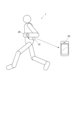
まず、図1を参照して、本実施の形態の全体構成を説明する。図1は、本実施の形態の走行軌跡表示システム1を示す概念図である。
First, the overall configuration of this embodiment will be described with reference to FIG. FIG. 1 is a conceptual diagram showing a travel
図1に示すように、走行軌跡表示システム1は、測位装置10と、軌跡作成及び表示装置20とを備える。
As shown in FIG. 1, the travel
測位装置10は、当該装置を装着したユーザの動きや位置を逐次検知可能な各種のセンサが内蔵された装置である。測位装置10は、例えば、ランニング時にユーザの腰に装着され、当該ランニング時に取得されるセンシング情報に基づいて逐次、測位を実行する装置である。また、測位装置10は、測位実行した測位結果を軌跡作成及び表示装置20に出力する。
The
軌跡作成及び表示装置20は、ランニング時にユーザが携帯可能な装置であり、測位装置10から得た測位結果を元に走行軌跡を示す軌跡情報を作成し、走行軌跡を表示する。この軌跡作成及び表示装置20としては、例えば、スマートフォンや、腕時計型表示器等のウェアラブル端末等が挙げられる。
The trajectory creation and
次に、図2を参照して、測位装置10の内部の機能構成を説明する。図2は、測位装置10の機能構成を示すブロック図である。
Next, with reference to FIG. 2, the internal functional configuration of the
図2に示すように、測位装置10は、制御部11と、記憶部12と、GNSS計測部13と、角速度計測部14と、加速度計側部15と、軸補正部16と、信号処理部17と、送信部18とを備える。
As shown in FIG. 2, the
制御部11は、CPU(Central Processing Unit)、RAM(Random Access Memory)等により構成される。制御部11のCPUは、記憶部12に記憶されているシステムプログラムや各種処理プログラムを読み出してRAM内に展開し、展開されたプログラムに従って各種処理を実行し、測位装置10各部の動作を制御する。
The
記憶部12は、不揮発性の半導体メモリやハードディスク等により構成される。記憶部12は、制御部11で実行される各種プログラムやプログラムにより処理の実行に必要なパラメータを記憶する。また、記憶部12は、信号処理部17による処理結果等のデータを記憶する。
The
GNSS計測部(測位手段、第2の導出手段)13は、測位装置10の現在位置(緯度、経度、高度)や、方位、速度等を計測する部分であり、GNSS(Global Navigation Satellite System)受信機が用いられる。GNSS計測部13は、所定時間(例えば、1秒)ごとに、測位装置10の現在位置、方位、速度等を示すGNSSデータを信号処理部17に出力する。
The GNSS measuring unit (positioning means, second deriving means) 13 is a part that measures the current position (latitude, longitude, altitude), direction, speed, etc. of the
角速度計測部(第1の導出手段)14は、測位装置10の角速度を計測する部分であり、ジャイロセンサが用いられる。角速度計測部14は、互いに直交する3軸方向を中心とする角速度を所定のサンプリング周期(例えば、200Hz)で検出する。そして、角速度計測部14は、検出された各軸を中心とする角速度に対応する角速度データを軸補正部16に出力する。
The angular velocity measuring unit (first deriving means) 14 is a part that measures the angular velocity of the
加速度計側部15は、測位装置10の加速度を計測する部分であり、加速度センサが用いられる。加速度計側部15は、互いに直交する3軸方向の加速度を所定のサンプリング周期(例えば、200Hz)で検出する。そして、加速度計側部15は、検出された各軸の加速度に対応する加速度データを軸補正部16に出力する。
The
軸補正部16は、角速度計測部14及び加速度計側部15より入力された各データ、すなわちセンサ座標系を基準とする各データをランニング動作に対して普遍なワールド座標系を基準とするデータに変換する。そして、軸補正部16は、変換されたワールド座標系を基準とするデータを信号処理部17に出力する。なお、センサ座標系からワールド座標系へのデータの変換方法は、公知であるため詳しい説明は省略する。
The
信号処理部(予測手段、第1の修正手段、第1の算出手段、第2の修正手段、第2の算出手段、決定手段、出力手段)17は、軸補正部16でセンサ座標系からワールド座標系へ変換された鉛直軸回りの角速度データを、GNSS計測部13で計測された方位データ(GNSS方位データ)を用いて修正するジャイロ方位修正処理(後述)を行う。
また、信号処理部17は、上記のジャイロ方位修正処理によって修正された角速度データに基づいて、測位装置10の次の進行方向を予測し、GNSS計測部13で計測された位置データ(GNSS位置データ)を当該予測された次の進行方向に基づいて修正するGNSS位置修正処理(後述)を行う。
なお、信号処理部17は、所定のロジック回路から構成されているが、当該構成は一例であってこれに限られるものではない。例えば、信号処理部17は、その処理の内容に応じてロジック回路と制御部11の両方で分担して当該処理を実行するようにしても良い。
The signal processing section (prediction means, first correction means, first calculation means, second correction means, second calculation means, determination means, output means) 17 uses the
Further, the
Note that, although the
送信部18は、測位装置10で測位実行した測位結果を軌跡作成及び表示装置20に送信する部分であり、例えば、USB端子などの有線式の通信部や、Bluetooth(登録商標)などの無線規格を採用した送信部である。
The transmitting
次に、図3及び図4を参照して、信号処理部17で実行されるジャイロ方位修正処理を説明する。図3は、ジャイロ方位修正処理を行うロジック回路の構成を示すブロック図である。図4(a)は、ローパスフィルタ(LPF)103に掛けられた後の鉛直軸回りの角速度を示すグラフである。図4(b)は、積分器104によって積分された角速度の積分値(角度)を示すグラフである。図4(c)は、ランニング1周期ごとにホールドした角度(角速度の積分値)を示すグラフである。
Next, with reference to FIGS. 3 and 4, the gyro azimuth correction process executed by the
図3に示すように、まず、走行検出部101は、GNSS計測部13から1秒ごとに出力される速度データ(GNSS速度データ)に基づいて、ユーザによる走行が開始されたか否かを判定する。具体的には、走行検出部101は、例えば、GNSS速度データの値が2秒連続して6km/hを超えた場合、走行が開始されたと判定し、走行が開始された時間を示す信号を出力する。
As shown in FIG. 3, first, the running
次いで、走行開始方位検出部102は、GNSS計測部13から1秒ごとに出力される方位データ(GNSS方位データ)、及び、走行検出部101から出力された信号に基づいて、走行が開始された時間に対応するGNSS方位データを取得して、当該GNSS方位データを出力する。
Next, the running start
次いで、積分器104は、走行開始方位検出部102から出力されたGNSS方位データに基づいて、当該GNSSデータの値を積分初期値としてセットする。そして、積分器104は、ローパスフィルタ(LPF)103に掛けられた後の鉛直軸回りの角速度データ(図4(a)参照)に基づいて、角速度の値を積分していく。一方、0越え検出部105は、ローパスフィルタ(LPF)103に掛けられた後の鉛直軸回りの角速度データ(図4(a)参照)に基づいて、鉛直軸回りの角速度が負から正へと転ずる各タイミングをランニング1周期ごとの開始点として検出し、当該開始点を示すデータを出力する。
ここで、鉛直軸回りの角速度データは、軸補正部16でセンサ座標系からワールド座標系へ変換された角速度データである。
Next, the
Here, the angular velocity data around the vertical axis is angular velocity data converted from the sensor coordinate system to the world coordinate system by the
ローパスフィルタ103は、ユーザの足が地面に着地したときの衝撃等によるノイズは除去するが、方向転換による成分は除去されない程度のカットオフ周波数(例えば、1Hz)に設定されたフィルタである。
The low-
保持器106は、積分器104によって積分された角速度の積分値(角度)を示すデータ(図4(b)参照)、及び、0越え検出部105によって検出されたランニング1周期ごとの開始点を示すデータに基づいて、ランニング1周期ごとにホールドした角度(角速度の積分値)を示すデータ(図4(c)参照)を出力する。そして、ランニング1周期ごとにホールドした角度を示すデータとGNSS方位データとに基づいて、当該ランニング1周期ごとにホールドした角度とGNSS方位との誤差が算出される。そして、ローパスフィルタ107によって、当該誤差がフィルタリング(カットオフ数十秒程度)され、フィルタリングされた誤差がランニング1周期ごとにホールドした角度にフィードバックされ修正されることにより、ジャイロ方位を示すデータが出力されることとなる。
上述した処理は、ジャイロセンサの角速度から計算したジャイロ方位は環境の影響を受けない(場所毎の誤差は少ない)が、ジャイロオフセットの蓄積誤差が生じる、一方、GNSS方位は周辺の建物等によって場所毎の誤差を生じることはあるが蓄積誤差は生じない、という特徴を利用し、ジャイロ方位を長周期(数十秒程度)GNSS方位にロックさせることで正確な方位を得るものである。
The
In the process described above, the gyro orientation calculated from the angular velocity of the gyro sensor is not affected by the environment (the error for each location is small), but an accumulated error of gyro offset occurs.On the other hand, the GNSS orientation is affected by the location due to surrounding buildings, etc. Taking advantage of the characteristic that there are occasional errors but no accumulated errors, accurate orientation is obtained by locking the gyro orientation to the GNSS orientation over a long period (about several tens of seconds).
次に、図5~図7を参照して、信号処理部17で実行されるGNSS位置修正処理を説明する。図5は、GNSS位置修正処理を行うロジック回路の構成を示すブロック図である。図6(a)及び(b)は、予測方位の求め方を示す説明図である。図7(a)及び(b)は、軌跡作成及び表示装置20に出力される測位結果である最終的な現在位置の求め方を示す説明図である。
Next, the GNSS position correction process executed by the
図5及び図6に示すように、まず、第1混合部111は、前回(1秒前)の走行方位dr1(=dr2)と、上述のジャイロ方位修正処理により得られたジャイロ方位dr3とを所定の割合(例えば、1:4の割合)で混合した方位を予測方位dr4(図6(a)及び(b)参照)として出力する。ここで、走行方位dr2は、前回(1秒前)の走行方位dr1を延長したものである。
As shown in FIGS. 5 and 6, first, the
次いで、ベクトル更新部112は、図5及び図7(a)に示すように、第1混合部111から出力された予測方位dr4上において、後述する比較部113により採用された速度分進めた位置を次の位置座標P2として出力する。
Next, as shown in FIGS. 5 and 7(a), the
比較部113は、図5及び図7(a)に示すように、次のGNSS座標ベクトルdr5を予測方位dr4上に射影したGNSS更新ベクトルdr6の速度成分と予測速度との比率を算出する。そして、当該予測速度に対するGNSS更新ベクトルdr6の速度成分の比率の値が所定の範囲(e.g.0.8~1.5)内にある場合、比較部113は、GNSS更新ベクトルdr6の速度成分を速度として採用する。一方、当該予測速度に対するGNSS更新ベクトルdr6の速度成分の比率の値が所定の範囲の上限値を超える場合、当該上限値に対応する速度成分を速度として採用し、また、当該比率の値が所定の範囲の下限値を下回る場合、当該下限値に対応する速度成分を速度として採用する。
このように、採用する速度を予測速度により制限をかけるのは、例えば、高架下をくぐるときなどは、GNSS位置座標が高架手前では押し戻され、高架通過後は一気に跳んでしまうといった不具合を抑制するためである。
ここで、予測速度は、ユーザの走行状態を示すピッチとストライドを用いて算出される。ストライドは、過去の走行距離をピッチで割ることにより算出されたものである。
As shown in FIGS. 5 and 7(a), the
In this way, limiting the speed to be adopted based on the predicted speed prevents problems such as when passing under an overpass, the GNSS position coordinates are pushed back before the overpass and jump all at once after passing the overpass. It's for a reason.
Here, the predicted speed is calculated using pitch and stride that indicate the user's running condition. Stride is calculated by dividing past distance traveled by pitch.
第2混合部115は、図5及び図7(b)に示すように、混合比作成部114で作成された混合比に基づいて、元のGNSS位置座標P1を混合することにより、次の位置座標P2を修正し、更新されたGNSS位置座標(最終座標)P3を出力する。ここで、最終座標として更新されたGNSS位置座標が軌跡作成及び表示装置20に逐次出力されることによって、軌跡作成及び表示装置20において走行軌跡が作成されることとなる。
As shown in FIGS. 5 and 7(b), the
混合比作成部114は、所定の時間間隔を空けて得られるジャイロ方位同士の差に基づいて、ユーザが走行する際の経路のカーブ度合いを判定することで混合比を決定する。
具体的には、混合比作成部114は、例えば、カーブの入りと出の角度差(ジャイロ推定)が20度未満の場合、元のGNSS位置座標P1の混合比を0.1とする。このように、カーブ度合いが低い場合、予測方位に基づく次の位置座標P2の重みを高めることで経路のうねりを抑制している。
また、混合比作成部114は、カーブの入りと出の角度差が20度以上60度未満の場合、当該角度差に応じて、元のGNSS位置座標P1の混合比を0.1~1の間で調整する。
また、混合比作成部114は、カーブの入りと出の角度差が60度以上の場合、元のGNSS位置座標P1の混合比を1とする。このように、カーブ度合いが高い場合、元のGNSS位置座標P1の重みを高めることで位置ずれを抑制している。
なお、上記の角度差と混合比は一例であり、適宜変更可能である。
The mixture
Specifically, the mixture
Further, when the angle difference between the entrance and exit of the curve is 20 degrees or more and less than 60 degrees, the mixture
Further, the mixture
Note that the above-mentioned angular difference and mixing ratio are merely examples, and can be changed as appropriate.
以上のように、本実施形態によれば、測位装置10は、GNSS計測部13によって、自装置の現在位置を逐次測位し、角速度計測部14によって、自装置の進行方向を逐次導出し、GNSS計測部13によって、自装置の進行方向を逐次導出し、角速度計測部14によって導出された進行方向を、GNSS計測部13によって導出された進行方向を用いて修正し、修正された進行方向に基づいて、次の進行方向を予測し、予測された次の進行方向(予測方位dr4)に基づいて、測位された現在位置を修正し、最終的な測位結果としたこととなる。
このため、測位装置10によれば、GNSS計測部13によって導出された進行方向と、角速度計測部14によって導出された進行方向とを併用することにより、例えば、市街地のようなマルチパスの多い場所でも正確な測位結果が得られる。
As described above, according to the present embodiment, the
Therefore, according to the
また、本実施形態によれば、測位装置10は、GNSS計測部13によって測位された現在位置と当該現在位置の測位の直前に測位された現在位置とを結ぶベクトル(次のGNSS座標ベクトルdr5)を、予測方位dr4に射影することにより、当該現在位置を修正したので、滑らかな軌跡を作成するための測位結果を得ることができる。
Further, according to the present embodiment, the
また、本実施形態によれば、測位装置10は、ユーザの走行状態から予測される予測速度に対するベクトル(GNSS更新ベクトルdr6)の速度成分の比率を算出し、当該比率の値が所定の範囲内にある場合、次の進行方向(予測方位dr4)に当該ベクトルの速度成分だけ進めた位置P2を修正後の現在位置としたこととなる。
このため、測位装置10によれば、次の位置P2を求める際に予測速度を用いて制限をかけることによって、より滑らかな軌跡を作成するための測位結果を得ることができる。
Further, according to the present embodiment, the
Therefore, according to the
また、本実施形態によれば、測位装置10は、上記比率の値が所定の範囲の上限値を超える場合、次の進行方向(予測方位dr4)に当該上限値に対応する速度成分だけ進めた位置P2を修正後の現在位置とし、当該比率の値が所定の範囲の下限値を下回る場合、前記次の進行方向に当該下限値に対応する速度成分だけ進めた位置P2を修正後の現在位置としたこととなる。
このため、測位装置10によれば、次の位置P2を求める際に予測速度を用いて制限をかけることによって、より滑らかな軌跡を作成するための測位結果を得ることができる。
Further, according to the present embodiment, when the value of the ratio exceeds the upper limit of the predetermined range, the
Therefore, according to the
また、本実施形態によれば、測位装置10は、ユーザが走行する際の経路のカーブ度合いに応じて、修正された現在位置P2を更に修正するので、より正確な測位結果を得ることができる。
Further, according to the present embodiment, the
また、本実施形態によれば、測位装置10は、ユーザが走行する際の経路のカーブ度合いを算出し、算出されたカーブ度合いに基づいて、混合比を決定し、決定された混合比に基づいて、修正された現在位置P2に対応する位置座標と、修正される前の現在位置P1に対応する位置座標とを混合することによって、修正された現在位置P2を更に修正したこととなる。
このため、測位装置10によれば、カーブ度合いが低い場合、例えば、予測方位dr4に基づく次の位置座標P2の重みを高めることで経路のうねりを抑制することができる。一方、カーブ度合いが高い場合、元のGNSS位置座標P1の重みを高めることで位置ずれを抑制することができる。
Further, according to the present embodiment, the
Therefore, according to the
なお、以上本発明の実施形態について説明したが、本発明は、かかる実施形態に限定されず、その要旨を逸脱しない範囲で、種々変形が可能であることは言うまでもない。 Although the embodiments of the present invention have been described above, it goes without saying that the present invention is not limited to these embodiments and can be modified in various ways without departing from the spirit thereof.
例えば、更新されたGNSS位置座標(最終座標)は、制御部11の制御下において、信号処理部17から出力されるごとに、送信部18を介して、軌跡作成及び表示装置20に送信される場合に限定されるものではない。かかる場合の他に、例えば、制御部11の制御下において、更新されたGNSS位置座標(最終座標)を記憶部12に逐次記憶しておき、ランニングの終了後に、記憶部12に記憶されている更新されたGNSS位置座標(最終座標)を読み出して、送信部18を介して、軌跡作成及び表示装置20に送信するようにしてもよい。
For example, the updated GNSS position coordinates (final coordinates) are transmitted to the trajectory creation and
また、本実施形態においては、測位装置10で逐次、測位を実行し、測位実行した測位結果を軌跡作成及び表示装置20に出力し、軌跡作成及び表示装置20において、測位装置10から得た測位結果を元に走行軌跡を示す軌跡情報を作成し、走行軌跡を表示したが、測位装置10において測位実行と軌跡情報の作成を行い、作成した軌跡情報を出力するようにしてもよい。
Further, in this embodiment, the
また、本実施形態においては、角速度計測部14によって導出された進行方向を、GNSS計測部13によって導出された進行方向を用いて修正し、修正された進行方向に基づいて、次の進行方向を予測したが、GNSS計測部13によって導出された進行方向を、角速度計測部14によって導出された進行方向を用いて修正し、修正された進行方向に基づいて、次の進行方向を予測してもよい。
言い換えれば、角速度計測部14によって導出された進行方向とGNSS計測部13によって導出された進行方向とから、次の進行方向を予測してもよい。
Furthermore, in this embodiment, the traveling direction derived by the angular
In other words, the next direction of travel may be predicted from the direction of travel derived by the angular
以上、本発明の実施形態を説明したが、本発明の範囲は、上述の実施の形態に限定するものではなく、特許請求の範囲に記載された発明の範囲をその均等の範囲を含む。
以下に、この出願の願書に最初に添付した特許請求の範囲に記載した発明を付記する。付記に記載した請求項の項番は、この出願の願書に最初に添付した特許請求の範囲の通りである。
Although the embodiments of the present invention have been described above, the scope of the present invention is not limited to the above-described embodiments, and includes the scope of the invention described in the claims and its equivalent range.
Below, the invention described in the claims first attached to the application of this application will be added. The claim numbers listed in the supplementary notes are as in the claims originally attached to the request for this application.
〔付記〕
<請求項1>
自装置の現在位置を逐次測位する測位手段と、
自装置の進行方向を逐次導出する第1の導出手段と、
前記第1の導出手段とは異なる方法で自装置の進行方向を逐次導出する第2の導出手段と、
前記第1の導出手段によって導出された進行方向と前記第2の導出手段によって導出された進行方向とを用いて、次の進行方向を予測する予測手段と、
前記予測手段によって予測された前記次の進行方向に基づいて、前記測位手段によって測位された現在位置を修正する第1の修正手段と、
を備えることを特徴とする測位装置。
<請求項2>
前記予測手段は、前記第1の導出手段によって導出された進行方向を、前記第2の導出手段によって導出された進行方向を用いて修正し、修正された進行方向に基づいて、次の進行方向を予測することを特徴とする請求項1に記載の測位装置。
<請求項3>
前記予測手段は、前記修正された進行方向に基づいて現在の進行方向を修正することにより、次の進行方向を予測することを特徴とする請求項1に記載の測位装置。
<請求項4>
前記第1の導出手段は、ジャイロセンサにより逐次検出される鉛直軸回りの角速度に基づいて、自装置の進行方向を逐次導出することを特徴とする請求項1~3のいずれか一項に記載の測位装置。
<請求項5>
前記測位手段は、衛星測位システムにより自装置の現在位置を逐次測位し、
前記第2の導出手段は、前記測位手段により逐次測位される現在位置に基づいて、自装置の進行方向を逐次導出することを特徴とする請求項1~4のいずれか一項に記載の測位装置。
<請求項6>
前記第1の修正手段は、前記測位手段によって測位された現在位置と当該現在位置の測位の直前に測位された現在位置とを結ぶベクトルを、前記予測手段によって予測された前記次の進行方向に射影することにより、当該現在位置を修正することを特徴とする請求項1~4のいずれか一項に記載の測位装置。
<請求項7>
ユーザの走行状態から予測される予測速度に対する前記ベクトルの速度成分の比率を算出する第1の算出手段を備え、
前記第1の修正手段は、前記第1の算出手段によって算出された前記比率の値が所定の範囲内にある場合、前記次の進行方向に前記ベクトルの速度成分だけ進めた位置を修正後の現在位置とすることを特徴とする請求項6に記載の測位装置。
<請求項8>
前記第1の修正手段は、前記第1の算出手段によって算出された前記比率の値が所定の範囲の上限値を超える場合、前記次の進行方向に当該上限値に対応する速度成分だけ進めた位置を修正後の現在位置とし、当該比率の値が所定の範囲の下限値を下回る場合、前記次の進行方向に当該下限値に対応する速度成分だけ進めた位置を修正後の現在位置とすることを特徴とする請求項7に記載の測位装置。
<請求項9>
ユーザが走行する際の経路のカーブ度合いに応じて、前記第1の修正手段によって修正された現在位置を更に修正する第2の修正手段を備えることを特徴とする請求項1~8のいずれか一項に記載の測位装置。
<請求項10>
前記予測手段によって予測された進行方向であり、且つ、所定の時間間隔を空けて得られる各進行方向に基づいて、前記経路のカーブ度合いを算出する第2の算出手段と、
前記第2の算出手段によって算出された前記カーブ度合いに基づいて、混合比を決定する決定手段と、を備え、
前記第2の修正手段は、前記決定手段によって決定された混合比に基づいて、前記第1の修正手段によって修正された現在位置に対応する位置座標と、修正される前の現在位置に対応する位置座標とを混合することによって、前記第1の修正手段によって修正された現在位置を更に修正することを特徴とする請求項9に記載の測位装置。
<請求項11>
前記第1の修正手段により修正された現在位置を出力する出力手段を備えることを特徴とする請求項1~10のいずれか一項に記載の測位装置。
<請求項12>
測位装置を用いた測位方法であって、
自装置の現在位置を逐次測位する測位工程と、
自装置の進行方向を逐次導出する第1の導出工程と、
前記第1の導出工程とは異なる方法で自装置の進行方向を逐次導出する第2の導出工程と、
前記第1の導出工程によって導出された進行方向と前記第2の導出工程によって導出された進行方向とを用いて、次の進行方向を予測する予測工程と、
前記予測工程によって予測された前記次の進行方向に基づいて、前記測位工程によって測位された現在位置を修正する修正工程と、
を含むことを特徴とする測位方法。
<請求項13>
測位装置のコンピュータを、
自装置の現在位置を逐次測位する測位手段、
自装置の進行方向を逐次導出する第1の導出手段、
前記第1の導出手段とは異なる方法で自装置の進行方向を逐次導出する第2の導出手段、 前記第1の導出手段によって導出された進行方向と前記第2の導出手段によって導出された進行方向とを用いて、次の進行方向を予測する予測手段、
前記予測手段によって予測された前記次の進行方向に基づいて、前記測位手段によって測位された現在位置を修正する修正手段、
として機能させることを特徴とする測位プログラム。
[Additional notes]
<Claim 1>
a positioning means for sequentially positioning the current position of the own device;
first deriving means for sequentially deriving the traveling direction of the own device;
a second deriving means for sequentially deriving the traveling direction of the own device using a method different from the first deriving means;
prediction means for predicting the next direction of travel using the direction of travel derived by the first derivation means and the direction of travel derived by the second derivation means;
a first correction means for correcting the current position determined by the positioning means based on the next direction of travel predicted by the prediction means;
A positioning device comprising:
<Claim 2>
The prediction means corrects the traveling direction derived by the first deriving means using the traveling direction derived by the second deriving means, and determines the next traveling direction based on the corrected traveling direction. The positioning device according to
<Claim 3>
The positioning device according to
<Claim 4>
4. The first deriving means sequentially derives the traveling direction of the device based on the angular velocity around the vertical axis sequentially detected by a gyro sensor. positioning device.
<Claim 5>
The positioning means sequentially positions the current position of the own device using a satellite positioning system,
Positioning according to any one of
<Claim 6>
The first correction means changes a vector connecting the current position measured by the positioning means and the current position measured immediately before the positioning of the current position in the next traveling direction predicted by the prediction means. The positioning device according to
<Claim 7>
comprising a first calculation means for calculating the ratio of the speed component of the vector to the predicted speed predicted from the user's driving state;
When the value of the ratio calculated by the first calculation means is within a predetermined range, the first correction means calculates a position advanced by the velocity component of the vector in the next direction of movement after the correction. 7. The positioning device according to
<Claim 8>
When the value of the ratio calculated by the first calculation means exceeds an upper limit of a predetermined range, the first correction means advances the speed component in the next traveling direction by a velocity component corresponding to the upper limit. The position is set as the current position after correction, and if the value of the ratio is less than the lower limit value of the predetermined range, the position advanced by the speed component corresponding to the lower limit value in the next direction of travel is set as the current position after correction. The positioning device according to claim 7, characterized in that:
<Claim 9>
9. Any one of
<Claim 10>
a second calculating means for calculating the degree of curve of the route based on each traveling direction predicted by the predicting means and obtained at predetermined time intervals;
determining means for determining a mixing ratio based on the degree of curve calculated by the second calculating means,
The second correction means corresponds to the position coordinates corresponding to the current position corrected by the first correction means and the current position before correction, based on the mixture ratio determined by the determination means. 10. The positioning device according to claim 9, wherein the current position corrected by the first correction means is further corrected by mixing the current position with position coordinates.
<Claim 11>
The positioning device according to any one of
<Claim 12>
A positioning method using a positioning device,
a positioning step of sequentially determining the current position of the own device;
a first derivation step of successively deriving the traveling direction of the own device;
a second derivation step of sequentially deriving the traveling direction of the device using a method different from the first derivation step;
a prediction step of predicting the next direction of travel using the direction of travel derived by the first derivation step and the direction of travel derived by the second derivation step;
a correction step of correcting the current position determined in the positioning step based on the next traveling direction predicted in the prediction step;
A positioning method characterized by comprising:
<Claim 13>
The computer of the positioning device,
positioning means for sequentially positioning the current position of the own device;
first deriving means for sequentially deriving the traveling direction of the own device;
a second deriving means for sequentially deriving the traveling direction of the device using a method different from the first deriving means; the traveling direction derived by the first deriving means and the traveling direction derived by the second deriving means; prediction means for predicting the next direction of travel using the direction;
correction means for correcting the current position determined by the positioning means based on the next direction of travel predicted by the prediction means;
A positioning program characterized by functioning as a.
1 走行軌跡表示システム
10 測位装置
11 制御部
12 記憶部
13 GNSS計測部(測位手段、第2の導出手段)
14 角速度計測部(第1の導出手段)
15 加速度計測部
16 軸補正部
17 信号処理部(予測手段、第1の修正手段、第1の算出手段、第2の修正手段、第2の算出手段、決定手段、出力手段)
18 送信部
20 軌跡作成及び表示装置
1 Travel
14 Angular velocity measurement unit (first derivation means)
15
18
Claims (11)
自装置の進行方向を逐次導出する第1の導出手段と、
前記第1の導出手段とは異なる方法で自装置の進行方向を逐次導出する第2の導出手段と、
前記第1の導出手段によって導出された進行方向と前記第2の導出手段によって導出された進行方向とを用いて、次の進行方向を予測する予測手段と、
前記予測手段によって予測された前記次の進行方向に基づいて、前記測位手段によって測位された現在位置を修正する第1の修正手段と、
を備え、
前記予測手段は、前記第1の導出手段によって導出された進行方向を、前記第2の導出手段によって導出された進行方向を用いて修正し、前回の進行方向と、前記修正された進行方向と、を所定の割合で混合した方位を前記次の進行方向の予測方位として出力することを特徴とする測位装置。 a positioning means for sequentially positioning the current position of the own device;
first deriving means for sequentially deriving the traveling direction of the own device;
a second deriving means for sequentially deriving the traveling direction of the own device using a method different from the first deriving means;
prediction means for predicting the next direction of travel using the direction of travel derived by the first derivation means and the direction of travel derived by the second derivation means;
a first correction means for correcting the current position determined by the positioning means based on the next direction of travel predicted by the prediction means;
Equipped with
The prediction means corrects the traveling direction derived by the first deriving means using the traveling direction derived by the second deriving means, and calculates the previous traveling direction and the revised traveling direction. , at a predetermined ratio, as the predicted direction of the next direction of travel .
前記走行が開始された時間を示す信号に基づいて、前記走行が開始された時間に対応する方位データを前記第2の導出手段から取得し、
前記取得した方位データを用いて前記第1の導出手段によって導出された進行方向を修正することを特徴とする請求項4に記載の測位装置。 The prediction means determines whether or not the user has started running based on the speed data output from the positioning means, and if it is determined that the running has started, the prediction means generates a signal indicating the time when the running has started. output,
Obtaining azimuth data corresponding to the time when the traveling started from the second deriving means based on a signal indicating the time when the traveling started;
5. The positioning device according to claim 4, wherein the direction of travel derived by the first deriving means is corrected using the acquired azimuth data.
前記第2の算出手段によって算出された前記カーブ度合いに基づいて、混合比を決定する決定手段と、を備え、
前記第2の修正手段は、前記決定手段によって決定された混合比に基づいて、前記第1の修正手段によって修正された現在位置に対応する位置座標と、修正される前の現在位置に対応する位置座標とを混合することによって、前記第1の修正手段によって修正された現在位置を更に修正することを特徴とする請求項7に記載の測位装置。 a second calculating means for calculating the degree of curve of the route based on each traveling direction predicted by the predicting means and obtained at predetermined time intervals;
determining means for determining a mixing ratio based on the degree of curve calculated by the second calculating means,
The second correction means corresponds to the position coordinates corresponding to the current position corrected by the first correction means and the current position before correction, based on the mixture ratio determined by the determination means. 8. The positioning device according to claim 7, wherein the current position corrected by the first correction means is further corrected by mixing the current position with the position coordinates.
自装置の現在位置を逐次測位する測位工程と、
自装置の進行方向を逐次導出する第1の導出工程と、
前記第1の導出工程とは異なる方法で自装置の進行方向を逐次導出する第2の導出工程と、
前記第1の導出工程によって導出された進行方向と前記第2の導出工程によって導出された進行方向とを用いて、次の進行方向を予測する予測工程と、
前記予測工程によって予測された前記次の進行方向に基づいて、前記測位工程によって測位された現在位置を修正する修正工程と、
を含み、
前記予測工程は、前記第1の導出工程によって導出された進行方向を、前記第2の導出工程によって導出された進行方向を用いて修正し、前回の進行方向と、前記修正された進行方向と、を所定の割合で混合した方位を前記次の進行方向の予測方位として出力する工程を含むことを特徴とする測位方法。 A positioning method using a positioning device,
a positioning step of sequentially determining the current position of the own device;
a first derivation step of successively deriving the traveling direction of the own device;
a second derivation step of sequentially deriving the traveling direction of the device using a method different from the first derivation step;
a prediction step of predicting the next direction of travel using the direction of travel derived by the first derivation step and the direction of travel derived by the second derivation step;
a correction step of correcting the current position determined in the positioning step based on the next traveling direction predicted in the prediction step;
including;
The prediction step corrects the traveling direction derived by the first deriving step using the traveling direction derived by the second deriving step, and compares the previous traveling direction with the modified traveling direction. , at a predetermined ratio, as a predicted direction of the next direction of travel .
自装置の現在位置を逐次測位する測位手段、
自装置の進行方向を逐次導出する第1の導出手段、
前記第1の導出手段とは異なる方法で自装置の進行方向を逐次導出する第2の導出手段、
前記第1の導出手段によって導出された進行方向と前記第2の導出手段によって導出された進行方向とを用いて、次の進行方向を予測する予測手段、
前記予測手段によって予測された前記次の進行方向に基づいて、前記測位手段によって測位された現在位置を修正する修正手段、
として機能させ、
前記予測手段は、前記第1の導出手段によって導出された進行方向を、前記第2の導出手段によって導出された進行方向を用いて修正し、前回の進行方向と、前記修正された進行方向と、を所定の割合で混合した方位を前記次の進行方向の予測方位として出力することを特徴とする測位プログラム。 The computer of the positioning device,
positioning means for sequentially positioning the current position of the own device;
a first derivation means for successively deriving the traveling direction of the own device;
a second deriving means for sequentially deriving the traveling direction of the own device using a method different from the first deriving means;
Prediction means for predicting the next direction of travel using the direction of travel derived by the first derivation means and the direction of travel derived by the second derivation means;
correction means for correcting the current position determined by the positioning means based on the next direction of travel predicted by the prediction means;
function as
The prediction means corrects the traveling direction derived by the first deriving means using the traveling direction derived by the second deriving means, and calculates the previous traveling direction and the revised traveling direction. , at a predetermined ratio, as a predicted direction of the next direction of travel .
Priority Applications (1)
| Application Number | Priority Date | Filing Date | Title |
|---|---|---|---|
| JP2022174211A JP7400922B2 (en) | 2018-06-18 | 2022-10-31 | Positioning device, positioning method and positioning program |
Applications Claiming Priority (2)
| Application Number | Priority Date | Filing Date | Title |
|---|---|---|---|
| JP2018115115A JP7172159B2 (en) | 2018-06-18 | 2018-06-18 | Positioning device, positioning method and positioning program |
| JP2022174211A JP7400922B2 (en) | 2018-06-18 | 2022-10-31 | Positioning device, positioning method and positioning program |
Related Parent Applications (1)
| Application Number | Title | Priority Date | Filing Date |
|---|---|---|---|
| JP2018115115A Division JP7172159B2 (en) | 2018-06-18 | 2018-06-18 | Positioning device, positioning method and positioning program |
Publications (2)
| Publication Number | Publication Date |
|---|---|
| JP2022189953A JP2022189953A (en) | 2022-12-22 |
| JP7400922B2 true JP7400922B2 (en) | 2023-12-19 |
Family
ID=69096113
Family Applications (2)
| Application Number | Title | Priority Date | Filing Date |
|---|---|---|---|
| JP2018115115A Active JP7172159B2 (en) | 2018-06-18 | 2018-06-18 | Positioning device, positioning method and positioning program |
| JP2022174211A Active JP7400922B2 (en) | 2018-06-18 | 2022-10-31 | Positioning device, positioning method and positioning program |
Family Applications Before (1)
| Application Number | Title | Priority Date | Filing Date |
|---|---|---|---|
| JP2018115115A Active JP7172159B2 (en) | 2018-06-18 | 2018-06-18 | Positioning device, positioning method and positioning program |
Country Status (1)
| Country | Link |
|---|---|
| JP (2) | JP7172159B2 (en) |
Families Citing this family (1)
| Publication number | Priority date | Publication date | Assignee | Title |
|---|---|---|---|---|
| WO2024101674A1 (en) * | 2022-11-11 | 2024-05-16 | 삼성전자주식회사 | System for detecting direction of movement, wearable electronic device, and method for detecting direction of movement in said system and said wearable electronic device |
Citations (7)
| Publication number | Priority date | Publication date | Assignee | Title |
|---|---|---|---|---|
| JP2000055678A (en) | 1998-08-04 | 2000-02-25 | Denso Corp | Current position detecting device for vehicle |
| JP2000321069A (en) | 1999-05-12 | 2000-11-24 | Tokimec Inc | Azimuth angle-detecting device |
| JP2000346663A (en) | 1999-06-01 | 2000-12-15 | Mitsubishi Electric Corp | Locator apparatus |
| JP2007206010A (en) | 2006-02-06 | 2007-08-16 | Alpine Electronics Inc | Method for determining travel angle of position calculator |
| JP2016114515A (en) | 2014-12-16 | 2016-06-23 | 株式会社Jvcケンウッド | Azimuth estimation device and azimuth estimation method |
| JP2016180626A (en) | 2015-03-23 | 2016-10-13 | カシオ計算機株式会社 | Electronic equipment, error correcting method, and program |
| JP2017106842A (en) | 2015-12-10 | 2017-06-15 | 三菱重工業株式会社 | Position measuring device, position measuring method and program |
Family Cites Families (2)
| Publication number | Priority date | Publication date | Assignee | Title |
|---|---|---|---|---|
| JP3320981B2 (en) * | 1996-07-01 | 2002-09-03 | 三菱電機株式会社 | Locator device |
| JP2000193466A (en) | 1998-12-25 | 2000-07-14 | Casio Comput Co Ltd | Navigation device, plot display method, and recording medium |
-
2018
- 2018-06-18 JP JP2018115115A patent/JP7172159B2/en active Active
-
2022
- 2022-10-31 JP JP2022174211A patent/JP7400922B2/en active Active
Patent Citations (7)
| Publication number | Priority date | Publication date | Assignee | Title |
|---|---|---|---|---|
| JP2000055678A (en) | 1998-08-04 | 2000-02-25 | Denso Corp | Current position detecting device for vehicle |
| JP2000321069A (en) | 1999-05-12 | 2000-11-24 | Tokimec Inc | Azimuth angle-detecting device |
| JP2000346663A (en) | 1999-06-01 | 2000-12-15 | Mitsubishi Electric Corp | Locator apparatus |
| JP2007206010A (en) | 2006-02-06 | 2007-08-16 | Alpine Electronics Inc | Method for determining travel angle of position calculator |
| JP2016114515A (en) | 2014-12-16 | 2016-06-23 | 株式会社Jvcケンウッド | Azimuth estimation device and azimuth estimation method |
| JP2016180626A (en) | 2015-03-23 | 2016-10-13 | カシオ計算機株式会社 | Electronic equipment, error correcting method, and program |
| JP2017106842A (en) | 2015-12-10 | 2017-06-15 | 三菱重工業株式会社 | Position measuring device, position measuring method and program |
Also Published As
| Publication number | Publication date |
|---|---|
| JP2019219196A (en) | 2019-12-26 |
| JP7172159B2 (en) | 2022-11-16 |
| JP2022189953A (en) | 2022-12-22 |
Similar Documents
| Publication | Publication Date | Title |
|---|---|---|
| CA3003298C (en) | Gnss and inertial navigation system utilizing relative yaw as an observable for an ins filter | |
| US20090088975A1 (en) | Navigation device | |
| US20240027194A1 (en) | Method and system for combining sensor data | |
| KR101796322B1 (en) | Apparatus and method for detecting location information using navigation algorithm | |
| JP5855249B2 (en) | Positioning device | |
| US8554504B2 (en) | Positioning apparatus, positioning method and storage medium for positioning of pedestrian by autonomous navigation | |
| US11079494B2 (en) | Positioning device | |
| US9759567B2 (en) | Position calculation method and position calculation device | |
| JP6395771B2 (en) | Vehicle position detection device, automatic steering control device, vehicle position detection method, and automatic steering control method | |
| JP5602070B2 (en) | POSITIONING DEVICE, POSITIONING METHOD OF POSITIONING DEVICE, AND POSITIONING PROGRAM | |
| US10809390B2 (en) | Positioning apparatus | |
| EP3864375A1 (en) | A method of estimating a metric of interest related to the motion of a body | |
| KR20120064048A (en) | Positioning apparatus, positioning method, and storage medium | |
| JP2012237606A (en) | Position calculation method and position calculation device | |
| CN111949030B (en) | Agricultural machinery positioning method, agricultural machinery vehicle and storage medium | |
| JP7400922B2 (en) | Positioning device, positioning method and positioning program | |
| CN109141470A (en) | Electronic equipment, error calibration method and recording medium | |
| JP2007003461A (en) | Apparatus for measuring angle of side slip of mobile station | |
| JP2008256620A (en) | Map data correction device, method, and program | |
| JP6419242B2 (en) | Moving distance measuring device, moving distance measuring method, and moving distance measuring program | |
| JP2020056741A (en) | Distance calculating device, distance calculating method, and distance calculating program | |
| JPH08334338A (en) | Gps navigation apparatus | |
| JPH07294269A (en) | Mobile positioning system | |
| JP2013250144A (en) | Navigation device, information presentation apparatus, speed detection method, and speed detection program | |
| CN111148015B (en) | Positioning method and device, mobile terminal, Android system terminal and Android system application system |
Legal Events
| Date | Code | Title | Description |
|---|---|---|---|
| A521 | Request for written amendment filed |
Free format text: JAPANESE INTERMEDIATE CODE: A523 Effective date: 20221109 |
|
| A621 | Written request for application examination |
Free format text: JAPANESE INTERMEDIATE CODE: A621 Effective date: 20221109 |
|
| A131 | Notification of reasons for refusal |
Free format text: JAPANESE INTERMEDIATE CODE: A131 Effective date: 20230725 |
|
| A521 | Request for written amendment filed |
Free format text: JAPANESE INTERMEDIATE CODE: A523 Effective date: 20230914 |
|
| TRDD | Decision of grant or rejection written | ||
| A01 | Written decision to grant a patent or to grant a registration (utility model) |
Free format text: JAPANESE INTERMEDIATE CODE: A01 Effective date: 20231107 |
|
| A61 | First payment of annual fees (during grant procedure) |
Free format text: JAPANESE INTERMEDIATE CODE: A61 Effective date: 20231120 |
|
| R150 | Certificate of patent or registration of utility model |
Ref document number: 7400922 Country of ref document: JP Free format text: JAPANESE INTERMEDIATE CODE: R150 |