JP7400915B1 - Pump system and vehicle equipped with it - Google Patents
Pump system and vehicle equipped with it Download PDFInfo
- Publication number
- JP7400915B1 JP7400915B1 JP2022153387A JP2022153387A JP7400915B1 JP 7400915 B1 JP7400915 B1 JP 7400915B1 JP 2022153387 A JP2022153387 A JP 2022153387A JP 2022153387 A JP2022153387 A JP 2022153387A JP 7400915 B1 JP7400915 B1 JP 7400915B1
- Authority
- JP
- Japan
- Prior art keywords
- flow path
- chamber
- pump
- way valve
- fluid
- Prior art date
- Legal status (The legal status is an assumption and is not a legal conclusion. Google has not performed a legal analysis and makes no representation as to the accuracy of the status listed.)
- Active
Links
- 239000012530 fluid Substances 0.000 claims abstract description 60
- 230000008929 regeneration Effects 0.000 claims description 4
- 238000011069 regeneration method Methods 0.000 claims description 4
- 230000001105 regulatory effect Effects 0.000 claims 1
- 230000010349 pulsation Effects 0.000 abstract description 11
- 238000010586 diagram Methods 0.000 abstract description 10
- 238000005086 pumping Methods 0.000 description 8
- 230000006870 function Effects 0.000 description 5
- 238000005336 cracking Methods 0.000 description 3
- 238000010276 construction Methods 0.000 description 2
- 238000007599 discharging Methods 0.000 description 1
- 238000006073 displacement reaction Methods 0.000 description 1
- 238000004519 manufacturing process Methods 0.000 description 1
- 230000007659 motor function Effects 0.000 description 1
Images


Landscapes
- Fluid-Pressure Circuits (AREA)
- Forklifts And Lifting Vehicles (AREA)
Abstract
【課題】複数の流路に接続されたポンプユニットの系統数を減らしつつ、複動型シリンダを駆動する際の圧力脈動の発生を抑制する。【解決手段】ポンプシステム100は、ポンプユニット10と、蓄圧器30と、第1チャンバ22及び第2チャンバ23を有する複動型シリンダ20と、第1流路L1a,L1bと、第2流路L1c,L1dと、第2流路L1c,L1dと流体用タンク70を接続する第3流路L1eと、第4流路L2と、第2流路L1c,L1dと第3流路L1eの接続箇所に設けられた三方弁24と、制御部60と、を備える。三方弁24は、ポンプユニット10から第1チャンバ22に流体を送出する場合、第2流路L1dから第2流路L1cへ流体が流れるように流路を切り替えられ、ポンプユニット10から第2チャンバ23に流体を送出する場合、第2流路L1cから第3流路L1eへ流体が流れるように流路を切り替えられる。【選択図】図2The present invention suppresses the occurrence of pressure pulsations when driving a double-acting cylinder while reducing the number of pump units connected to a plurality of flow paths. A pump system 100 includes a pump unit 10, a pressure accumulator 30, a double-acting cylinder 20 having a first chamber 22 and a second chamber 23, first flow paths L1a, L1b, and a second flow path. L1c, L1d, a third flow path L1e that connects the second flow paths L1c, L1d and the fluid tank 70, a fourth flow path L2, and a connection point between the second flow paths L1c, L1d and the third flow path L1e. The three-way valve 24 and the control section 60 are provided. When the three-way valve 24 sends fluid from the pump unit 10 to the first chamber 22, the flow path is switched so that the fluid flows from the second flow path L1d to the second flow path L1c. 23, the flow path can be switched so that the fluid flows from the second flow path L1c to the third flow path L1e. [Selection diagram] Figure 2
Description
本開示は、ポンプシステム及びそれを備えた車両に関する。 The present disclosure relates to a pump system and a vehicle equipped with the same.
従来、ポンプ機能及びモータ機能を備えた多系統のポンプが知られている。このような多系統のポンプは、ポンプに接続された複数の系統の流量を制御可能であり、搭載する機器に備わる油圧シリンダや油圧モータ、蓄圧器などの数に応じて、ポンプの系統数を決定する必要がある。 BACKGROUND ART Conventionally, multi-system pumps having a pump function and a motor function are known. Such multi-system pumps can control the flow rate of multiple systems connected to the pump, and the number of pump systems can be adjusted depending on the number of hydraulic cylinders, hydraulic motors, pressure accumulators, etc. in the installed equipment. Need to decide.
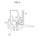
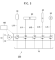
ここで、図5及び図6を用いて、多系統のポンプをフォークリフトに適用した場合の従来例について説明する。図5に示す車両101は、図6に示すポンプシステム200を備えたフォークリフトである。図6は、従来例に係るポンプシステム200を示す油圧回路図であり、ポンプシステム200をフォークリフトに搭載した場合の例である。
Here, a conventional example in which a multi-system pump is applied to a forklift will be described using FIGS. 5 and 6.
従来例のポンプシステム200は、モータ部11及びポンプ部12を有するポンプユニット10と、ポンプユニット10と接続される流体用タンク70と、ポンプユニット10を制御する制御部160と、を備える。また、ポンプユニット10は、流路L13を介して蓄圧器30と接続され、流路L14を介してリフト用の単動型シリンダ40と接続され、流路L15を介してタイヤ駆動用の油圧モータ50と接続されている。また、ポンプユニット10は、流路L11及び流路L12という2つの系統を使用してチルト用の複動型シリンダ20を駆動するよう構成されている。
The
また、特許文献1には、蓄圧器と複動型シリンダの第1チャンバを連通路により接続し、さらに、ポンプとしての機能とモータとしての機能を切り替え可能な第1作動部の高圧ポートと上記連通路を連通させることが開示されている。また、特許文献1には、第1作動部をポンプとして機能させて、複動型シリンダの第2チャンバに流体を供給するとともに、第1チャンバ内の流体を連通路を介して蓄圧器に排出することで、複動型シリンダのピストンを一方向に移動させること、及び、第1作動部をモータとして機能させて、蓄圧器から上記連通路を介して第1チャンバへと流体を供給するとともに、第2チャンバ内の流体を外部に排出することで、複動型シリンダのピストンを他方向に移動することが開示されている。 Furthermore, Patent Document 1 discloses that a pressure accumulator and a first chamber of a double-acting cylinder are connected by a communication passage, and that a high-pressure port of a first actuating part that can switch between a function as a pump and a function as a motor; It is disclosed that the communication path is communicated. Further, Patent Document 1 discloses that the first actuating section is made to function as a pump to supply fluid to the second chamber of the double-acting cylinder, and discharge fluid in the first chamber to the pressure accumulator via a communication path. By doing so, the piston of the double-acting cylinder is moved in one direction, the first actuating section is made to function as a motor, and fluid is supplied from the pressure accumulator to the first chamber via the communication path. , it is disclosed that the piston of the double-acting cylinder is moved in the other direction by discharging the fluid in the second chamber to the outside.
ポンプが備える系統数が多くなると、ポンプのサイズや部品(例えば、バルブ部品、配管部品、コントローラ、配線部品など)の数が増大し、製造コストも増加するという問題がある。そのため、なるべく少ない系統数でポンプを構成したいというニーズがある。 As the number of systems included in a pump increases, the size of the pump and the number of parts (for example, valve parts, piping parts, controllers, wiring parts, etc.) increase, and manufacturing costs also increase. Therefore, there is a need to configure a pump with as few systems as possible.
系統数は搭載する機器に必要なシリンダやモータの数に応じて決められるが、中でも複動型シリンダは動作のために2つの系統を使用するため、複動型シリンダが多く備わる機器では必要な系統数が増加しやすい。特に、建設機械などでは複動型シリンダが多く備わるため、多系統のポンプを適用する場合に系統数の増加が起きやすい。 The number of systems is determined according to the number of cylinders and motors required for the installed equipment, but double-acting cylinders use two systems for operation, so equipment equipped with many double-acting cylinders requires The number of strains tends to increase. In particular, construction machinery and the like are equipped with many double-acting cylinders, so when applying multi-system pumps, the number of systems tends to increase.
特許文献1では、蓄圧器と複動型シリンダの第1チャンバをともに共通の連通路を介して第1作動部に接続することにより、系統数を削減している。しかし、特許文献1に記載の流体圧回路装置には、第1チャンバ内の流体を連通路を介して蓄圧器に排出して第1チャンバ側にピストンを動かす場合における圧力脈動の抑制という点において、改善の余地があった。 In Patent Document 1, the number of systems is reduced by connecting both the pressure accumulator and the first chamber of the double-acting cylinder to the first actuating section via a common communication path. However, the fluid pressure circuit device described in Patent Document 1 has a problem in suppressing pressure pulsations when the fluid in the first chamber is discharged to the pressure accumulator via the communication path and the piston is moved toward the first chamber. , there was room for improvement.
本開示は、上記の課題に鑑みてなされたものである。すなわち、本開示は、複数の流路に接続されたポンプユニットの系統数を減らしつつ、複動型シリンダを駆動する際の圧力脈動の発生を抑制することを目的とする。 The present disclosure has been made in view of the above problems. That is, an object of the present disclosure is to suppress the occurrence of pressure pulsations when driving a double-acting cylinder while reducing the number of pump units connected to a plurality of flow paths.
本開示の一実施形態に係るポンプシステムは、
複数の流路に接続されたポンプユニットと、
エネルギー回生用の蓄圧器と、
第1チャンバ及び第2チャンバを有する複動型シリンダと、
前記ポンプユニットと前記蓄圧器を接続する第1流路と、
前記第1チャンバと前記第1流路を接続する第2流路と、
前記第2流路と流体用タンクを接続する第3流路と、
前記ポンプユニットと前記第2チャンバを接続する第4流路と、
前記第2流路と前記第3流路の接続箇所に設けられた三方弁と、
前記三方弁による流路の切り替えを制御する制御部と、を備え、
前記三方弁は、前記制御部からの制御信号に基づいて、
前記ポンプユニットから前記第1チャンバに流体を送出する場合、前記三方弁よりも前記第1流路側の前記第2流路から前記三方弁よりも前記第1チャンバ側の前記第2流路へ流体が流れるように流路を切り替えられ、
前記ポンプユニットから前記第2チャンバに流体を送出する場合、前記三方弁よりも前記第1チャンバ側の前記第2流路から前記第3流路へ流体が流れるように流路を切り替えられる。
A pump system according to an embodiment of the present disclosure includes:
A pump unit connected to multiple flow paths,
A pressure accumulator for energy regeneration,
a double-acting cylinder having a first chamber and a second chamber;
a first flow path connecting the pump unit and the pressure accumulator;
a second flow path connecting the first chamber and the first flow path;
a third flow path connecting the second flow path and the fluid tank;
a fourth flow path connecting the pump unit and the second chamber;
a three-way valve provided at a connection point between the second flow path and the third flow path;
a control unit that controls switching of the flow path by the three-way valve,
The three-way valve, based on a control signal from the control section,
When sending fluid from the pump unit to the first chamber, the fluid is sent from the second flow path closer to the first flow path than the three-way valve to the second flow path closer to the first chamber than the three-way valve. The flow path can be switched so that the
When sending fluid from the pump unit to the second chamber, the flow path is switched so that the fluid flows from the second flow path closer to the first chamber than the three-way valve to the third flow path.
本開示によれば、複数の流路に接続されたポンプユニットの系統数を減らしつつ、複動型シリンダを駆動する際の圧力脈動の発生を抑制することができる。 According to the present disclosure, it is possible to reduce the number of systems of pump units connected to a plurality of flow paths while suppressing the occurrence of pressure pulsations when driving a double-acting cylinder.
以下、本開示の一実施形態に係るポンプシステム及び車両について図面を参照しながら説明する。各図面において、同一又は同等の構成要素には同一の符号を付し、重複する説明を適宜省略する。また、各図面に示された各構成要素の寸法は、説明の便宜上のものであって、実際の寸法とは異なる場合がある。 Hereinafter, a pump system and a vehicle according to an embodiment of the present disclosure will be described with reference to the drawings. In each drawing, the same or equivalent components are denoted by the same reference numerals, and redundant explanations will be omitted as appropriate. Further, the dimensions of each component shown in each drawing are for convenience of explanation, and may differ from actual dimensions.
まず、図1及び図2を用いて、本開示の一実施形態に係るポンプシステム及び車両について説明する。図1に示す車両1は、図2に示すポンプシステム100を備えたフォークリフトである。フォークリフトは、ポンプシステム100を適用できる車両の一例である。ポンプシステム100は、油圧ショベル等の他の車両に適用することもできる。また、ポンプシステム100は、車両ではなく、工作機械や建設機械等の他の機械に適用してもよい。
First, a pump system and a vehicle according to an embodiment of the present disclosure will be described using FIGS. 1 and 2. Vehicle 1 shown in FIG. 1 is a forklift truck equipped with
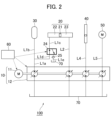
図2に示すように、本開示の一実施形態に係るポンプシステム100は、ポンプユニット10と、複動型シリンダ20と、蓄圧器30と、単動型シリンダ40と、油圧モータ50と、制御部60と、流体用タンク70と、を備える。また、ポンプシステム100は、第1流路L1a,L1bと、第2流路L1c,L1dと、第3流路L1eと、第4流路L2と、流路L3~5と、三方弁24と、逆止弁25と、を備える。本実施形態において、ポンプシステム100は油圧式であり、流体として油を用いるものであるが、ポンプシステム100は、油以外の他の流体を用いてもよい。
As shown in FIG. 2, a
ポンプユニット10は、モータ部11と、ポンプ部12と、を有する。モータ部11は、ポンプ部12の駆動源となるエンジンである。ポンプ部12は、例えば、可変容量型のポンプであって、複数の流路に接続されている。ポンプユニット10は、制御部60からの制御信号に基づいて、ポンプユニット10に接続された各流路へのポンピングやモータリングを行う。
The
蓄圧器30は、エネルギー回生用に設けられており、流体を高圧状態で貯留可能である。蓄圧器30は、第1流路L1a,L1bを介してポンプ部12と接続される。第1流路L1a,L1bは、第2流路L1c,L1dを介して第1チャンバ22と接続される。第1流路L1aは、第1流路L1a,L1bと第2流路L1dとの接続箇所よりもポンプユニット10側の流路である。第1流路L1bは、第1流路L1a,L1bと第2流路L1dとの接続箇所よりも蓄圧器30側の流路である。また、詳しくは後述するが、蓄圧器30は、複動型シリンダ20のピストン運動に関与する。
The
単動型シリンダ40は、リフト用のシリンダであり、フォークリフトのフォークのリフト動作に関与する。単動型シリンダ40は、流路L4を介してポンプ部12と接続される。油圧モータ50は、フォークリフトのタイヤを駆動させるためのモータである。油圧モータ50は、流路L5を介してポンプ部12と接続される。流体用タンク70は、流体として用いる油を貯蔵する。本実施形態において、流体用タンク70は、複数の流路を介してポンプ部12に接続されている。
The single-acting
複動型シリンダ20は、フォークリフトのフォークのチルト動作に関与する。複動型シリンダ20は、ピストン21と、第1チャンバ22と、第2チャンバ23と、を有する。第1チャンバ22は、三方弁24を有する第2流路L1c,L1dを介して第1流路L1a,L1bと接続される。第2流路L1cは、三方弁24よりも複動型シリンダ20側の流路である。第2流路L1dは、三方弁24よりもポンプユニット10側の流路である。第3流路L1eは、三方弁24に接続され、第2流路L1c,L1dと流体用タンク70を連通させる。逆止弁25は、第3流路L1e上に設けられる。第2チャンバ23は、第4流路L2を介してポンプ部12と接続される。
The double-acting
三方弁24は、第2流路L1c,L1dと第3流路L1eの接続箇所に設けられている。三方弁24は、制御部60からの制御信号に基づいて、第2流路L1cと第2流路L1dを連通させた経路と、第2流路L1cと第3流路L1eを連通させた経路と、を切り替える。三方弁24の構造は、特に限定されず、従来公知の構造を適宜採用できる。逆止弁25は、流体用タンク70から三方弁24に向かう方向の流れを規制する。逆止弁25の構造は、特に限定されず、従来公知の構造を適宜採用できる。また、逆止弁25は、クラッキング圧力により流路内の最低圧力を規制している。逆止弁25のクラッキング圧力は、例えば、0.2~5MPaであることが好ましい。なお、逆止弁25が閉じた状態において、第3流路L1e内の圧力は、流体用タンク70内の圧力と同じであり、例えば、大気圧程度である。
The three-
制御部60は、例えば、CPU(Central Processing Unit)、ROM(Read Only Memory)、RAM(Random Access Memory)等を有している。CPUは、ROMから処理内容に応じたプログラムを読み出してRAMに展開し、展開したプログラムと協働してポンプシステム100の各種の制御を行う。
The
制御部60は、例えば、操作者によるフォークリフトの操作を入力情報とし、該入力情報等に基づいて、モータ部11、ポンプ部12、及び三方弁24の動作を制御する。制御部60は、例えば、ポンプ部12における各流路との接続ポートに設けられた電磁弁(図示せず)への電流供給を制御する制御信号を出力し、電磁弁の開閉を制御することで、各流路に対するポンピングやモータリングを個別に制御しうる。制御部60が入力情報等に基づいてモータ部11やポンプ部12の動作を制御することにより、フォークリフトは、操作者の操作に従った各種の動作を行う。また、制御部60は、例えば、三方弁24内の経路を切り替えるための制御信号を出力し、第2流路L1cと第2流路L1dを連通させた経路と、第2流路L1cと第3流路L1eを連通させた経路と、の切り替えを制御する。
The
次に、図3及び図4を用いて、図2に示すポンプシステム100における複動型シリンダ20の動作について説明する。図3は、図2に示すポンプシステムにおける複動型シリンダの動作の一例を示す模式図である。具体的には、図2は、ピストン21を第1チャンバ22側へ移動させる場合の動作例である。
Next, the operation of the double-acting
図3の例において、ポンプユニット10は、第4流路L2へポンピングを実施して流体を送り出し、第2チャンバ23側の圧力を第1チャンバ22側の圧力よりも高めている。第4流路L2へポンピングを実施する場合、制御部60からの制御信号に基づいて、三方弁24は、第2流路L1cと第3流路L1eを連通させた経路に切り替えられる。そして、第1チャンバ22内の流体は、第1チャンバ22側と第2チャンバ23側との圧力差によって第2流路L1cへと押し出され、逆止弁25のクラッキング圧力に到達した段階で、第3流路L1eを通って流体用タンク70へ送られる。これらの動作で生じる差圧によって、ピストン21は第1チャンバ22側へ移動することになる。
In the example of FIG. 3, the
図3の例において、第1チャンバ22側の流体は、ポンプユニット10のモータリングによって抜かれるのではなく、第1チャンバ22と流体用タンク70との差圧によって、流体用タンク70に送られる。そのため、ポンプユニット10によるモータリングを実施する場合よりも、第1チャンバ22内の急な圧力変化が生じにくく、複動型シリンダを駆動する際の圧力脈動の発生を抑制することができる。また、その結果として、シリンダ動作がギクシャクしたり、シリンダが振動したりすることを抑制でき、同様に、ピストン21の作動損失を増加させにくくすることができる。
In the example of FIG. 3, the fluid on the
また、逆止弁25を備えることにより、第1チャンバ22内の圧力が必要以上に低くなってしまうことを抑制でき、結果として、複動型シリンダを駆動する際の圧力脈動の発生をさらに抑制することができる。その結果として、シリンダ動作がギクシャクしたり、シリンダが振動したりすることをさらに抑制でき、同様に、ピストン21の作動損失をさらに増加させにくくすることができる。
Furthermore, by providing the
図4は、図2に示すポンプシステム100における複動型シリンダ20の動作の他の例を示す模式図である。具体的には、図4は、ピストン21を第2チャンバ23側へ移動させる場合の動作例である。
FIG. 4 is a schematic diagram showing another example of the operation of the double-acting
図4の例において、ポンプユニット10は、第4流路L2へモータリングを実施して流体を抜き、第2チャンバ23側の圧力を第1チャンバ22側の圧力よりも低くする。また、第4流路L2へモータリングを実施する場合、制御部60からの制御信号に基づいて、三方弁24は、第2流路L1cと第2流路L1dを連通させた経路に切り替えられる。そして、例えば、ポンプユニット10が第1流路L1aへポンピングを実施して流体を送り出し、第2流路L1cと第2流路L1dを通って、流体が第1チャンバ22へと供給される。これらの動作で生じる差圧によって、ピストン21は第2チャンバ23側へ移動することになる。
In the example of FIG. 4, the
また、図4の例において、ポンプユニット10が第1流路L1aへポンピングを実施すると、流体の一部は第1流路L1bを通って蓄圧器30へと送られる。蓄圧器30に十分に流体が十分に貯留されている場合、ポンプユニット10による第1流路L1aへポンピングを実施せずに、蓄圧器30から第1チャンバ22へと流体を供給してもよい。蓄圧器30から流体を供給することで、圧力脈動の発生を抑制しやすくなる。また、複動型シリンダ20を動作させていないとき等に、三方弁24を第2流路L1cと第3流路L1eを連通させた経路に切り替えて、ポンプユニット10から第1流路L1aへポンピングを実施することで、事前に蓄圧器30内に流体が十分に貯留されている状態にしておいてもよい。流体の供給先をポンプユニット10にするか蓄圧器30にするかは、例えば、蓄圧器30に貯留された流体の量、言い換えると、蓄圧器30に蓄積されたエネルギー量に応じて、制御部60によって制御されうる。
Moreover, in the example of FIG. 4, when the
以上、本開示に係る一実施形態について詳述したが、本発明は上述の実施形態に限定されるものではなく、適宜、変形、改良等が可能である。例えば、ポンプシステム100は、単動型シリンダ40、及び油圧モータ50のうちの1以上を備えていなくともよいし、他の構成要素を含んでいてもよい。本発明には、特許請求の範囲によって示され、特許請求の範囲と均等の意味及び範囲内でのすべての変更が含まれる。
Although one embodiment according to the present disclosure has been described in detail above, the present invention is not limited to the above-described embodiment, and can be modified, improved, etc. as appropriate. For example, the
[付記]
以上のとおり、本明細書には次の事項が開示されている。
(1) 複数の流路に接続されたポンプユニットと、
エネルギー回生用の蓄圧器と、
第1チャンバ及び第2チャンバを有する複動型シリンダと、
前記ポンプユニットと前記蓄圧器を接続する第1流路と、
前記第1チャンバと前記第1流路を接続する第2流路と、
前記第2流路と流体用タンクを接続する第3流路と、
前記ポンプユニットと前記第2チャンバを接続する第4流路と、
前記第2流路と前記第3流路の接続箇所に設けられた三方弁と、
前記三方弁による流路の切り替えを制御する制御部と、を備え、
前記三方弁は、前記制御部からの制御信号に基づいて、
前記ポンプユニットから前記第1チャンバに流体を送出する場合、前記三方弁よりも前記第1流路側の前記第2流路から前記三方弁よりも前記第1チャンバ側の前記第2流路へ流体が流れるように流路を切り替えられ、
前記ポンプユニットから前記第2チャンバに流体を送出する場合、前記三方弁よりも前記第1チャンバ側の前記第2流路から前記第3流路へ流体が流れるように流路を切り替えられる、
ポンプシステム。
このポンプシステムによれば、複数の流路に接続されたポンプユニットの系統数を減らしつつ、複動型シリンダを駆動する際の圧力脈動の発生を抑制することができる。
具体的には、蓄圧器と第1チャンバとを、三方弁によって分岐させた流路でポンプユニットに接続したことで、系統数を1つ減らした構成としている。よって、ポンプシステムのコンパクト化、軽量化、低コスト化を実現できる。
また、ポンプユニットから第2チャンバに流体を送出する場合、三方弁よりも第1チャンバ側の第2流路から第3流路へ流体が流れるように流路を切り替えることにより、第1チャンバ側の流体は、ポンプユニットのモータリングによって抜かれるのではなく、第1チャンバと流体用タンクとの差圧によって、流体用タンクに送られることになる。そのため、ポンプユニットによるモータリングを実施する場合よりも、第1チャンバ内の急な圧力変化が生じにくく、複動型シリンダを駆動する際の圧力脈動の発生を抑制することができる。また、その結果として、例えば、シリンダ動作がギクシャクしたり、シリンダが振動したりすることを抑制でき、同様に、ピストンの作動損失を増加させにくくすることができる。
[Additional notes]
As mentioned above, the following matters are disclosed in this specification.
(1) A pump unit connected to multiple channels,
A pressure accumulator for energy regeneration,
a double-acting cylinder having a first chamber and a second chamber;
a first flow path connecting the pump unit and the pressure accumulator;
a second flow path connecting the first chamber and the first flow path;
a third flow path connecting the second flow path and the fluid tank;
a fourth flow path connecting the pump unit and the second chamber;
a three-way valve provided at a connection point between the second flow path and the third flow path;
a control unit that controls switching of the flow path by the three-way valve,
The three-way valve, based on a control signal from the control section,
When sending fluid from the pump unit to the first chamber, the fluid is sent from the second flow path closer to the first flow path than the three-way valve to the second flow path closer to the first chamber than the three-way valve. The flow path can be switched so that the
When sending fluid from the pump unit to the second chamber, the flow path is switched so that the fluid flows from the second flow path closer to the first chamber than the three-way valve to the third flow path.
pump system.
According to this pump system, it is possible to reduce the number of pump units connected to a plurality of flow paths and to suppress the occurrence of pressure pulsations when driving a double-acting cylinder.
Specifically, the pressure accumulator and the first chamber are connected to the pump unit through a flow path branched by a three-way valve, thereby reducing the number of systems by one. Therefore, the pump system can be made more compact, lighter, and lower in cost.
In addition, when sending fluid from the pump unit to the second chamber, by switching the flow path so that the fluid flows from the second flow path on the first chamber side to the third flow path than the three-way valve, the first chamber side The fluid is not removed by the motoring of the pump unit, but is sent to the fluid tank by the differential pressure between the first chamber and the fluid tank. Therefore, sudden pressure changes in the first chamber are less likely to occur than when motoring is performed by the pump unit, and it is possible to suppress the occurrence of pressure pulsations when driving the double-acting cylinder. Further, as a result, for example, it is possible to suppress jerky cylinder operation and vibration of the cylinder, and similarly, it is possible to make it difficult to increase the operating loss of the piston.
(2) さらに、前記第3流路上に、前記三方弁に向かう方向の流れを規制する逆止弁を備える、
上記(1)に記載のポンプシステム。
このポンプシステムによれば、三方弁よりも第1チャンバ側の第2流路から第3流路へ流体が流れるように流路を切り替えた場合に、第1チャンバ内の圧力が必要以上に低くなってしまうことを抑制でき、結果として、複動型シリンダを駆動する際の圧力脈動の発生をさらに抑制することができる。
(2) Further, a check valve is provided on the third flow path to regulate the flow in the direction toward the three-way valve.
The pump system according to (1) above.
According to this pump system, when the flow path is switched so that the fluid flows from the second flow path closer to the first chamber than the three-way valve to the third flow path, the pressure in the first chamber becomes lower than necessary. As a result, it is possible to further suppress the occurrence of pressure pulsations when driving the double-acting cylinder.
(3) 上記(1)又は(2)に記載のポンプシステムを備える車両。
この車両によれば、系統数を少なくしてコンパクト化、軽量化、低コスト化が可能なポンプシステムを備えているので、車両のコンパクト化、軽量化、低コスト化が可能である。また、上記のポンプシステムは複動型シリンダにおける圧力脈動の発生を抑制できるものなので、車両の操作中にシリンダ動作のギクシャクやシリンダの振動が生じにくく、また、複動型シリンダでの作動損失が増加しにくくなる。
(3) A vehicle equipped with the pump system described in (1) or (2) above.
This vehicle is equipped with a pump system that can be made compact, lightweight, and low cost by reducing the number of systems, so the vehicle can be made compact, lightweight, and low cost. In addition, since the above pump system can suppress the occurrence of pressure pulsations in the double-acting cylinder, jerky cylinder operation and cylinder vibration are less likely to occur during vehicle operation, and operational loss in the double-acting cylinder is reduced. It becomes difficult to increase.
1,101:車両
10:ポンプユニット
11:モータ部
12:ポンプ部
20:複動型シリンダ
21:ピストン
22:第1チャンバ
23:第2チャンバ
24:三方弁
25:逆止弁
30:蓄圧器
40:単動型シリンダ
50:油圧モータ
60,160:制御部
70:流体用タンク
100,200:ポンプシステム
L1a,L1b:第1流路
L1c,L1d:第2流路
L1e:第3流路
L2:第4流路
L3~5,L11~15:流路
1,101: Vehicle 10: Pump unit 11: Motor section 12: Pump section 20: Double acting cylinder 21: Piston 22: First chamber 23: Second chamber 24: Three-way valve 25: Check valve 30: Pressure accumulator 40 : Single acting cylinder 50:
Claims (3)
エネルギー回生用の蓄圧器と、
第1チャンバ及び第2チャンバを有する複動型シリンダと、
前記ポンプユニットと前記蓄圧器を接続する第1流路と、
前記第1チャンバと前記第1流路を接続する第2流路と、
前記第2流路と流体用タンクを接続する第3流路と、
前記ポンプユニットと前記第2チャンバを接続する第4流路と、
前記第2流路と前記第3流路の接続箇所に設けられた三方弁と、
前記三方弁による流路の切り替えを制御する制御部と、を備え、
前記三方弁は、前記制御部からの制御信号に基づいて、
前記ポンプユニットから前記第1チャンバに流体を送出する場合、前記三方弁よりも前記第1流路側の前記第2流路から前記三方弁よりも前記第1チャンバ側の前記第2流路へ流体が流れるように流路を切り替えられ、
前記ポンプユニットから前記第2チャンバに流体を送出する場合、前記三方弁よりも前記第1チャンバ側の前記第2流路から前記第3流路へ流体が流れるように流路を切り替えられる、
ポンプシステム。 A pump unit connected to multiple flow paths,
A pressure accumulator for energy regeneration,
a double-acting cylinder having a first chamber and a second chamber;
a first flow path connecting the pump unit and the pressure accumulator;
a second flow path connecting the first chamber and the first flow path;
a third flow path connecting the second flow path and the fluid tank;
a fourth flow path connecting the pump unit and the second chamber;
a three-way valve provided at a connection point between the second flow path and the third flow path;
a control unit that controls switching of the flow path by the three-way valve,
The three-way valve, based on a control signal from the control section,
When sending fluid from the pump unit to the first chamber, the fluid is sent from the second flow path closer to the first flow path than the three-way valve to the second flow path closer to the first chamber than the three-way valve. The flow path can be switched so that the
When sending fluid from the pump unit to the second chamber, the flow path is switched so that the fluid flows from the second flow path closer to the first chamber than the three-way valve to the third flow path.
pump system.
請求項1に記載のポンプシステム。 Further, a check valve is provided on the third flow path for regulating flow in a direction toward the three-way valve.
A pump system according to claim 1.
A vehicle comprising the pump system according to claim 1 or claim 2.
Priority Applications (1)
| Application Number | Priority Date | Filing Date | Title |
|---|---|---|---|
| JP2022153387A JP7400915B1 (en) | 2022-09-27 | 2022-09-27 | Pump system and vehicle equipped with it |
Applications Claiming Priority (1)
| Application Number | Priority Date | Filing Date | Title |
|---|---|---|---|
| JP2022153387A JP7400915B1 (en) | 2022-09-27 | 2022-09-27 | Pump system and vehicle equipped with it |
Publications (2)
| Publication Number | Publication Date |
|---|---|
| JP7400915B1 true JP7400915B1 (en) | 2023-12-19 |
| JP2024047728A JP2024047728A (en) | 2024-04-08 |
Family
ID=89190279
Family Applications (1)
| Application Number | Title | Priority Date | Filing Date |
|---|---|---|---|
| JP2022153387A Active JP7400915B1 (en) | 2022-09-27 | 2022-09-27 | Pump system and vehicle equipped with it |
Country Status (1)
| Country | Link |
|---|---|
| JP (1) | JP7400915B1 (en) |
Citations (4)
| Publication number | Priority date | Publication date | Assignee | Title |
|---|---|---|---|---|
| JP5464273B2 (en) | 2010-07-09 | 2014-04-09 | 日産自動車株式会社 | Vehicle left and right wheel driving force distribution control device |
| WO2018039791A1 (en) | 2016-08-30 | 2018-03-08 | University Of Saskatchewan | A hydraulic system with linear actuators and hydrostatic and non-hydrostatic modes |
| US20200018329A1 (en) | 2017-03-29 | 2020-01-16 | Voith Patent Gmbh | Apparatus for controlling a hydraulic machine |
| JP7160009B2 (en) | 2019-09-27 | 2022-10-25 | いすゞ自動車株式会社 | Hydraulic circuit device and vehicle |
-
2022
- 2022-09-27 JP JP2022153387A patent/JP7400915B1/en active Active
Patent Citations (4)
| Publication number | Priority date | Publication date | Assignee | Title |
|---|---|---|---|---|
| JP5464273B2 (en) | 2010-07-09 | 2014-04-09 | 日産自動車株式会社 | Vehicle left and right wheel driving force distribution control device |
| WO2018039791A1 (en) | 2016-08-30 | 2018-03-08 | University Of Saskatchewan | A hydraulic system with linear actuators and hydrostatic and non-hydrostatic modes |
| US20200018329A1 (en) | 2017-03-29 | 2020-01-16 | Voith Patent Gmbh | Apparatus for controlling a hydraulic machine |
| JP7160009B2 (en) | 2019-09-27 | 2022-10-25 | いすゞ自動車株式会社 | Hydraulic circuit device and vehicle |
Also Published As
| Publication number | Publication date |
|---|---|
| JP2024047728A (en) | 2024-04-08 |
Similar Documents
| Publication | Publication Date | Title |
|---|---|---|
| US9080310B2 (en) | Closed-loop hydraulic system having regeneration configuration | |
| US10280594B2 (en) | Hydraulic energy regeneration system for work machine | |
| US9932995B2 (en) | Hydraulic excavator drive system | |
| US20090120084A1 (en) | Hydraulic Unit | |
| WO2005031172A1 (en) | Hydraulic control device of industrial machinery | |
| JP2015090192A (en) | Fluid pressure circuit and working machine | |
| GB2566232A (en) | Hydraulic drive system | |
| US20160153473A1 (en) | Shovel | |
| JP2010014244A (en) | Construction machinery | |
| JP2019052703A (en) | Hydraulic drive system for construction machine | |
| WO2019188045A1 (en) | Wheel loader | |
| JP5823932B2 (en) | Hydraulic drive unit for construction machinery | |
| JP7400915B1 (en) | Pump system and vehicle equipped with it | |
| JP2016098955A (en) | Fluid pressure circuit and work machine | |
| US11371535B2 (en) | Fluid pressure circuit | |
| JP7263003B2 (en) | Excavators and control valves for excavators | |
| US10247206B2 (en) | Fluid circuit | |
| JPWO2019022164A1 (en) | Excavator | |
| JP7160009B2 (en) | Hydraulic circuit device and vehicle | |
| CN113825881B (en) | Hydraulic equipment, hydraulic system and working machine | |
| JP2018168976A (en) | Hydraulic system | |
| US11313104B2 (en) | Control system for construction machinery | |
| WO2023162884A1 (en) | Fluid pressure circuit | |
| JP2024047729A (en) | Pump system and vehicle equipped with same | |
| JP6510910B2 (en) | Hydraulic drive |
Legal Events
| Date | Code | Title | Description |
|---|---|---|---|
| A521 | Request for written amendment filed |
Free format text: JAPANESE INTERMEDIATE CODE: A523 Effective date: 20221019 |
|
| A621 | Written request for application examination |
Free format text: JAPANESE INTERMEDIATE CODE: A621 Effective date: 20221117 |
|
| RD02 | Notification of acceptance of power of attorney |
Free format text: JAPANESE INTERMEDIATE CODE: A7422 Effective date: 20230414 |
|
| RD04 | Notification of resignation of power of attorney |
Free format text: JAPANESE INTERMEDIATE CODE: A7424 Effective date: 20230616 |
|
| A521 | Request for written amendment filed |
Free format text: JAPANESE INTERMEDIATE CODE: A523 Effective date: 20230711 |
|
| A521 | Request for written amendment filed |
Free format text: JAPANESE INTERMEDIATE CODE: A523 Effective date: 20230711 |
|
| TRDD | Decision of grant or rejection written | ||
| A01 | Written decision to grant a patent or to grant a registration (utility model) |
Free format text: JAPANESE INTERMEDIATE CODE: A01 Effective date: 20231107 |
|
| A61 | First payment of annual fees (during grant procedure) |
Free format text: JAPANESE INTERMEDIATE CODE: A61 Effective date: 20231120 |
|
| R150 | Certificate of patent or registration of utility model |
Ref document number: 7400915 Country of ref document: JP Free format text: JAPANESE INTERMEDIATE CODE: R150 |