JP7399239B2 - In-vehicle antenna device - Google Patents

In-vehicle antenna device Download PDF

Info

Publication number
JP7399239B2
JP7399239B2 JP2022160046A JP2022160046A JP7399239B2 JP 7399239 B2 JP7399239 B2 JP 7399239B2 JP 2022160046 A JP2022160046 A JP 2022160046A JP 2022160046 A JP2022160046 A JP 2022160046A JP 7399239 B2 JP7399239 B2 JP 7399239B2
Authority
JP
Japan
Prior art keywords
antenna
antenna device
array
array antenna
average gain
Prior art date
Legal status (The legal status is an assumption and is not a legal conclusion. Google has not performed a legal analysis and makes no representation as to the accuracy of the status listed.)
Active
Application number
JP2022160046A
Other languages
Japanese (ja)
Other versions
JP2022176279A (en
Inventor
孝之 曽根
聖 岩崎
和也 松永
Current Assignee (The listed assignees may be inaccurate. Google has not performed a legal analysis and makes no representation or warranty as to the accuracy of the list.)
Yokowo Co Ltd
Original Assignee
Yokowo Co Ltd
Priority date (The priority date is an assumption and is not a legal conclusion. Google has not performed a legal analysis and makes no representation as to the accuracy of the date listed.)
Filing date
Publication date
Application filed by Yokowo Co Ltd filed Critical Yokowo Co Ltd
Publication of JP2022176279A publication Critical patent/JP2022176279A/en
Application granted granted Critical
Publication of JP7399239B2 publication Critical patent/JP7399239B2/en
Active legal-status Critical Current
Anticipated expiration legal-status Critical

Links

Images

Classifications

    • HELECTRICITY
    • H01ELECTRIC ELEMENTS
    • H01QANTENNAS, i.e. RADIO AERIALS
    • H01Q1/00Details of, or arrangements associated with, antennas
    • H01Q1/12Supports; Mounting means
    • HELECTRICITY
    • H01ELECTRIC ELEMENTS
    • H01QANTENNAS, i.e. RADIO AERIALS
    • H01Q19/00Combinations of primary active antenna elements and units with secondary devices, e.g. with quasi-optical devices, for giving the antenna a desired directional characteristic
    • H01Q19/10Combinations of primary active antenna elements and units with secondary devices, e.g. with quasi-optical devices, for giving the antenna a desired directional characteristic using reflecting surfaces
    • HELECTRICITY
    • H01ELECTRIC ELEMENTS
    • H01QANTENNAS, i.e. RADIO AERIALS
    • H01Q1/00Details of, or arrangements associated with, antennas
    • H01Q1/27Adaptation for use in or on movable bodies
    • H01Q1/32Adaptation for use in or on road or rail vehicles
    • H01Q1/325Adaptation for use in or on road or rail vehicles characterised by the location of the antenna on the vehicle
    • H01Q1/3275Adaptation for use in or on road or rail vehicles characterised by the location of the antenna on the vehicle mounted on a horizontal surface of the vehicle, e.g. on roof, hood, trunk
    • HELECTRICITY
    • H01ELECTRIC ELEMENTS
    • H01QANTENNAS, i.e. RADIO AERIALS
    • H01Q1/00Details of, or arrangements associated with, antennas
    • H01Q1/27Adaptation for use in or on movable bodies
    • H01Q1/32Adaptation for use in or on road or rail vehicles
    • HELECTRICITY
    • H01ELECTRIC ELEMENTS
    • H01QANTENNAS, i.e. RADIO AERIALS
    • H01Q1/00Details of, or arrangements associated with, antennas
    • H01Q1/36Structural form of radiating elements, e.g. cone, spiral, umbrella; Particular materials used therewith
    • HELECTRICITY
    • H01ELECTRIC ELEMENTS
    • H01QANTENNAS, i.e. RADIO AERIALS
    • H01Q1/00Details of, or arrangements associated with, antennas
    • H01Q1/50Structural association of antennas with earthing switches, lead-in devices or lightning protectors
    • HELECTRICITY
    • H01ELECTRIC ELEMENTS
    • H01QANTENNAS, i.e. RADIO AERIALS
    • H01Q15/00Devices for reflection, refraction, diffraction or polarisation of waves radiated from an antenna, e.g. quasi-optical devices
    • H01Q15/14Reflecting surfaces; Equivalent structures
    • HELECTRICITY
    • H01ELECTRIC ELEMENTS
    • H01QANTENNAS, i.e. RADIO AERIALS
    • H01Q21/00Antenna arrays or systems
    • H01Q21/0006Particular feeding systems
    • H01Q21/0025Modular arrays
    • HELECTRICITY
    • H01ELECTRIC ELEMENTS
    • H01QANTENNAS, i.e. RADIO AERIALS
    • H01Q21/00Antenna arrays or systems
    • H01Q21/06Arrays of individually energised antenna units similarly polarised and spaced apart
    • H01Q21/061Two dimensional planar arrays
    • H01Q21/062Two dimensional planar arrays using dipole aerials
    • HELECTRICITY
    • H01ELECTRIC ELEMENTS
    • H01QANTENNAS, i.e. RADIO AERIALS
    • H01Q21/00Antenna arrays or systems
    • H01Q21/29Combinations of different interacting antenna units for giving a desired directional characteristic
    • HELECTRICITY
    • H01ELECTRIC ELEMENTS
    • H01QANTENNAS, i.e. RADIO AERIALS
    • H01Q5/00Arrangements for simultaneous operation of antennas on two or more different wavebands, e.g. dual-band or multi-band arrangements
    • H01Q5/40Imbricated or interleaved structures; Combined or electromagnetically coupled arrangements, e.g. comprising two or more non-connected fed radiating elements
    • HELECTRICITY
    • H01ELECTRIC ELEMENTS
    • H01QANTENNAS, i.e. RADIO AERIALS
    • H01Q9/00Electrically-short antennas having dimensions not more than twice the operating wavelength and consisting of conductive active radiating elements
    • H01Q9/04Resonant antennas
    • H01Q9/0407Substantially flat resonant element parallel to ground plane, e.g. patch antenna
    • HELECTRICITY
    • H01ELECTRIC ELEMENTS
    • H01QANTENNAS, i.e. RADIO AERIALS
    • H01Q9/00Electrically-short antennas having dimensions not more than twice the operating wavelength and consisting of conductive active radiating elements
    • H01Q9/04Resonant antennas
    • H01Q9/30Resonant antennas with feed to end of elongated active element, e.g. unipole
    • H01Q9/32Vertical arrangement of element
    • H01Q9/36Vertical arrangement of element with top loading
    • HELECTRICITY
    • H01ELECTRIC ELEMENTS
    • H01QANTENNAS, i.e. RADIO AERIALS
    • H01Q1/00Details of, or arrangements associated with, antennas
    • H01Q1/27Adaptation for use in or on movable bodies
    • H01Q1/32Adaptation for use in or on road or rail vehicles
    • H01Q1/325Adaptation for use in or on road or rail vehicles characterised by the location of the antenna on the vehicle
    • HELECTRICITY
    • H01ELECTRIC ELEMENTS
    • H01QANTENNAS, i.e. RADIO AERIALS
    • H01Q21/00Antenna arrays or systems
    • H01Q21/0006Particular feeding systems
    • H01Q21/0031Parallel-plate fed arrays; Lens-fed arrays
    • HELECTRICITY
    • H01ELECTRIC ELEMENTS
    • H01QANTENNAS, i.e. RADIO AERIALS
    • H01Q21/00Antenna arrays or systems
    • H01Q21/06Arrays of individually energised antenna units similarly polarised and spaced apart
    • H01Q21/061Two dimensional planar arrays
    • H01Q21/065Patch antenna array

Landscapes

  • Physics & Mathematics (AREA)
  • Electromagnetism (AREA)
  • Engineering & Computer Science (AREA)
  • Remote Sensing (AREA)
  • Variable-Direction Aerials And Aerial Arrays (AREA)
  • Aerials With Secondary Devices (AREA)
  • Details Of Aerials (AREA)
  • Support Of Aerials (AREA)

Description

本発明は、車両に設置するV2X(Vehicle to X; Vehicle to Everything)通信等(車車間通信/路車間通信等)に用いるアンテナ装置に係り、特に複数種のアンテナを有する車載用アンテナ装置に関するものである。 The present invention relates to an antenna device installed in a vehicle and used for V2X (Vehicle to It is.

一般に、V2Xのアンテナとして水平面内指向性が無指向性のモノポールアンテナ等が検討されてきた。図28は、モノポールアンテナを円地板(直径1mの円形導体板)上に垂直に設置した場合の、周波数5887.5MHzでの垂直偏波のシミュレーションによる水平面内指向特性図である。モノポールアンテナの場合、図28に示すように平均利得が-0.86dBiであって利得が低く、車体ルーフ等に設置した時にV2X通信に要求される仕様を満足できない場合がある。 In general, monopole antennas with non-directional directivity in the horizontal plane have been considered as V2X antennas. FIG. 28 is a directional characteristic diagram in the horizontal plane based on a simulation of vertical polarization at a frequency of 5887.5 MHz when a monopole antenna is vertically installed on a circular ground plate (a circular conductor plate with a diameter of 1 m). In the case of a monopole antenna, as shown in FIG. 28, the average gain is -0.86 dBi, which is low, and when installed on the roof of a car body, it may not be able to meet the specifications required for V2X communication.

さらに近年では、一方向の平均利得が他方向の平均利得よりも高い車載用アンテナ装置が求められる場合がある。また、複数種類の通信を行うために、アンテナケース内に複数のアンテナが同梱されることも多くなっている。 Furthermore, in recent years, there has been a demand for an on-vehicle antenna device in which the average gain in one direction is higher than the average gain in the other direction. Furthermore, in order to perform multiple types of communication, multiple antennas are often included in an antenna case.

特許第5874780号公報Patent No. 5874780

本発明はこうした状況を認識してなされたものであり、複数のアンテナを備える場合において、それらのアンテナのうちの一つを、一方向の平均利得が他方向の平均利得よりも高く、所定方向の利得の向上を図ることが可能な車載用アンテナ装置を提供することを主たる目的とする。 The present invention has been made in recognition of such a situation, and when a plurality of antennas are provided, one of the antennas is connected in a predetermined direction so that the average gain in one direction is higher than the average gain in the other direction. The main purpose of the present invention is to provide an on-vehicle antenna device that can improve the gain of the vehicle.

本発明は、例えば車載用アンテナ装置として実施することができる。この車載用アンテナ装置は、車両に取り付けられるアンテナベースと、前記アンテナベース上のアンテナエレメントと、前記アンテナベースに設けられるホルダーと、前記ホルダーを前記車両に取り付ける取付具と、を備え、前記アンテナエレメントは前記ホルダーに保持され、前記取付具は、前記アンテナエレメントの動作周波数帯では前記アンテナエレメントの反射器又は導波器として機能することを特徴とする。 The present invention can be implemented, for example, as a vehicle-mounted antenna device. This in-vehicle antenna device includes an antenna base that is attached to a vehicle, an antenna element on the antenna base, a holder provided on the antenna base, and a fixture that attaches the holder to the vehicle, and the antenna element is held by the holder, and the fixture functions as a reflector or a waveguide for the antenna element in the operating frequency band of the antenna element.

本発明によれば、一方向の平均利得が他方向の平均利得よりも高く、所定方向の利得の向上を図ることが可能な車載用アンテナ装置を提供することができる。 According to the present invention, it is possible to provide an on-vehicle antenna device in which the average gain in one direction is higher than the average gain in the other direction, and the gain in a predetermined direction can be improved.

実施の形態1に係るアンテナ装置1の前方に向かって左側の側面図。FIG. 2 is a left side view of the antenna device 1 according to the first embodiment when viewed from the front. アンテナ装置1の前方に向かって右側の側面図。FIG. 2 is a side view of the right side of the antenna device 1 when viewed from the front. アンテナ装置1の右側後上方から見た要部斜視図。FIG. 2 is a perspective view of the main parts of the antenna device 1 seen from the upper right rear side. アンテナ装置1を上方から見た平面図。FIG. 2 is a plan view of the antenna device 1 viewed from above. アンテナ装置1の垂直偏波の水平面内の指向特性の比較図。FIG. 3 is a comparison diagram of the directivity characteristics of vertically polarized waves in the horizontal plane of the antenna device 1. FIG. アンテナ装置1の主要構成部材の配置及び寸法関係を示す側面図。FIG. 2 is a side view showing the arrangement and dimensional relationships of the main components of the antenna device 1. FIG. アンテナ装置1の隣接アンテナの有無による平均利得の差の比較図。FIG. 3 is a comparison diagram of the difference in average gain depending on the presence or absence of adjacent antennas in the antenna device 1. FIG. 実施の形態2に係るアンテナ装置2の前方に向かって左側の側面図。FIG. 2 is a left side view of the antenna device 2 according to Embodiment 2 when viewed from the front. アンテナ装置2の前方に向かって右側の側面図。FIG. 2 is a side view of the right side of the antenna device 2 when facing the front. アンテナ装置2の垂直偏波の水平面内の指向特性の比較図。FIG. 4 is a comparison diagram of the directivity characteristics of vertically polarized waves in the horizontal plane of the antenna device 2; アンテナ装置2の主要構成部材の配置及び寸法関係を示す側面図。FIG. 2 is a side view showing the arrangement and dimensional relationships of the main components of the antenna device 2. FIG. 実施の形態3に係るアンテナ装置3の前方に向かって左側の側面図。FIG. 7 is a left side view of the antenna device 3 according to Embodiment 3 when facing the front. アンテナ装置3の前方に向かって右側の側面図。FIG. 3 is a side view of the right side of the antenna device 3 as viewed from the front. アンテナ装置3の垂直偏波の水平面内の指向特性の比較図。FIG. 3 is a comparison diagram of the directivity characteristics of vertically polarized waves in the horizontal plane of the antenna device 3; アンテナ装置3の主要構成部材の配置及び寸法関係を示す側面図。FIG. 3 is a side view showing the arrangement and dimensional relationship of the main components of the antenna device 3. FIG. 実施の形態4に係るアンテナ装置4の前方に向かって左側の側面図。FIG. 4 is a left side view of the antenna device 4 according to Embodiment 4 as viewed from the front. アンテナ装置4の前方に向かって右側の側面図。FIG. 4 is a side view of the right side when facing the front of the antenna device 4. FIG. アンテナ装置4の上方から見た平面図。FIG. 4 is a plan view of the antenna device 4 seen from above. アンテナ装置4の右側後上方から見た斜視図。FIG. 4 is a perspective view of the antenna device 4 seen from the upper right rear side. アンテナ装置4の垂直偏波の水平面内の指向特性の比較図。FIG. 4 is a comparison diagram of the directivity characteristics of vertically polarized waves in the horizontal plane of the antenna device 4; アンテナ装置4の主要構成部材の配置及び寸法関係を示す側面図。FIG. 4 is a side view showing the arrangement and dimensional relationships of the main components of the antenna device 4. FIG. アンテナ装置4において容量装荷素子の前後方向の分割の有無によるパッチアンテナの周波数と軸比との関係を示す特性図。FIG. 4 is a characteristic diagram showing the relationship between the frequency and the axial ratio of the patch antenna depending on whether or not the capacitive loading element is divided in the front-back direction in the antenna device 4; アンテナ装置4において容量装荷素子の前後方向の分割の有無によるパッチアンテナの仰角10°における周波数と円偏波の平均利得との関係を示す特性図。FIG. 4 is a characteristic diagram showing the relationship between the frequency and the average gain of circularly polarized waves at an elevation angle of 10° of the patch antenna depending on whether or not the capacitive loading element is divided in the front-back direction in the antenna device 4; 実施の形態5に係るアンテナ装置5の前方に向かって左側の側面図。FIG. 6 is a left side view of the antenna device 5 according to the fifth embodiment when viewed from the front. アンテナ装置5の前方に向かって右側の側面図。FIG. 5 is a side view of the right side of the antenna device 5 when viewed from the front. アンテナ装置5の垂直偏波の水平面内の指向特性の比較図。FIG. 5 is a comparison diagram of the directivity characteristics of vertically polarized waves in the horizontal plane of the antenna device 5; アンテナ装置5の主要構成部材の配置及び寸法関係を示す側面図。FIG. 5 is a side view showing the arrangement and dimensional relationships of the main components of the antenna device 5. FIG. 一般的なモノポールアンテナの水平面内の指向特性図。Directional characteristic diagram in the horizontal plane of a general monopole antenna. 実施の形態6に係るアンテナ装置6の前方に向かって左側の側面図。FIG. 6 is a left side view of the antenna device 6 according to the sixth embodiment when facing the front. アンテナ装置6をその左側後上方から見た斜視図。FIG. 6 is a perspective view of the antenna device 6 viewed from the left rear and upper side thereof. アンテナ装置6の垂直偏波の水平面内の指向特性の比較図。FIG. 4 is a comparison diagram of the directivity characteristics of vertically polarized waves in the horizontal plane of the antenna device 6; 実施の形態7に係るアンテナ装置7の前方に向かって左側の側面図。FIG. 7 is a left side view of the antenna device 7 according to Embodiment 7 when viewed from the front. アンテナ装置7のアンテナと金属体の距離に応じた後方利得特性図。FIG. 7 is a diagram showing rear gain characteristics depending on the distance between the antenna of the antenna device 7 and the metal body. (a)は実施の形態8に係るアンテナ装置8のうち前方に向かって左側の部分側面図、(b)は環状部を支持する支持部の構造を後方側からみた部分斜視図。(a) is a partial side view of the left side when facing the front of the antenna device 8 according to Embodiment 8, and (b) is a partial perspective view of the structure of the support section that supports the annular section, viewed from the rear side.

以下、図面を参照しながら本発明の実施の形態例を詳述する。なお、各図面に示される同一または同等の構成要素、部材等には同一の符号を付し、適宜重複した説明は省略する。なお、各実施の形態は、本発明の構成等を限定するものではなく、例示である。 Embodiments of the present invention will be described in detail below with reference to the drawings. Note that the same or equivalent components, members, etc. shown in each drawing are given the same reference numerals, and redundant explanations will be omitted as appropriate. Note that each embodiment does not limit the configuration of the present invention, but is merely an illustration.

<実施の形態1>
図1は本発明の実施の形態1に係るアンテナ装置1の前方に向かって左側の側面図である。図2は同じく前方に向かって右側の側面図である。図3はアンテナ装置1の右側後上方から見た斜視図である。図4はアンテナ装置1を上方から見た平面図である。図1において、紙面の左方向をアンテナ装置1の前方向、右方向をアンテナ装置1の後方向、紙面の上方向をアンテナ装置1の上方向、紙面の下方向をアンテナ装置1の下方向と定義する。
<Embodiment 1>
FIG. 1 is a front left side view of an antenna device 1 according to Embodiment 1 of the present invention. FIG. 2 is a side view of the right side facing the front. FIG. 3 is a perspective view of the antenna device 1 viewed from the upper right rear side. FIG. 4 is a plan view of the antenna device 1 viewed from above. In FIG. 1, the left side of the page is the front of the antenna device 1, the right side is the back of the antenna device 1, the top of the page is the top of the antenna device 1, and the bottom of the page is the bottom of the antenna device 1. Define.

図1から図4に示すように、実施の形態1に係るアンテナ装置1は、第1のアンテナの一例となるアレイアンテナ基板10と、第2のアンテナの一例となるAM/FM放送用アンテナ素子50とを相互に隣接(近接)するようにアンテナベース80上に備えている。アレイアンテナ基板10には、同時給電可能な二つのダイポールアンテナ・アレイ30を有する。各ダイポールアンテナ・アレイ30は、例えばV2X通信用の動作周波数帯、例えば5887.5MHzでの送信又は受信に適したサイズに設計されている。AM/FM放送用アンテナ素子50は、容量装荷素子60及びヘリカル素子70を有する。容量装荷素子60は、アンテナベース80を指向する面部とアレイアンテナ基板10を指向する縁部とを有する板状導体の一例となる素子である。ヘリカル素子70は、線状導体素子の一例となる素子であり、容量装荷素子60と協働でAM波帯(526kHz~1605kHz)及びFM波帯(76MHz~90MHz)で動作する。すなわち、これらの周波数帯の信号の受信を可能にする。 As shown in FIGS. 1 to 4, the antenna device 1 according to the first embodiment includes an array antenna substrate 10, which is an example of a first antenna, and an AM/FM broadcasting antenna element, which is an example of a second antenna. 50 are provided on the antenna base 80 so as to be adjacent to (near) each other. The array antenna board 10 has two dipole antenna arrays 30 that can be fed simultaneously. Each dipole antenna array 30 is designed to have a size suitable for transmission or reception in an operating frequency band for V2X communication, for example 5887.5 MHz. The AM/FM broadcast antenna element 50 includes a capacitive loading element 60 and a helical element 70. The capacitive loading element 60 is an element that is an example of a plate-shaped conductor having a surface portion oriented toward the antenna base 80 and an edge portion oriented toward the array antenna substrate 10 . The helical element 70 is an example of a linear conductive element, and operates in the AM wave band (526 kHz to 1605 kHz) and the FM wave band (76 MHz to 90 MHz) in cooperation with the capacitive loading element 60. In other words, it is possible to receive signals in these frequency bands.

アレイアンテナ基板10は、アンテナベース80の上方向に設けられる絶縁樹脂等の誘電体基板20を有する。誘電体基板20には、第1の面(前方に向かって右側の側面)と第2の面(前方に向かって左側の側面)とが形成され、第1の面に銅箔等の第1の導体パターン21、第2の面に銅箔等の第2の導体パターン22がそれぞれ形成されている。
第1の導体パターン21と第2の導体パターン22は、それぞれ、垂直偏波用のダイポールアンテナ・アレイ30及び伝送線路40として動作する。なお、各導体パターン21、第2の導体パターン22は、銅箔を貼り付けた基板のエッチング、基板面への導体の印刷、めっき等で形成することができる。
The array antenna substrate 10 includes a dielectric substrate 20 made of insulating resin or the like provided above the antenna base 80 . The dielectric substrate 20 has a first surface (a side surface on the right side when facing the front) and a second surface (a side surface on the left side when facing the front), and a first surface made of copper foil or the like is formed on the first surface. A conductor pattern 21 and a second conductor pattern 22 made of copper foil or the like are respectively formed on the second surface.
The first conductor pattern 21 and the second conductor pattern 22 operate as a vertically polarized dipole antenna array 30 and a transmission line 40, respectively. Note that each conductor pattern 21 and the second conductor pattern 22 can be formed by etching a substrate to which copper foil is attached, printing a conductor on the substrate surface, plating, or the like.

各面のダイポールアンテナ・アレイ30は、それぞれ上下方向に一直線となるように配列され、同位相で給電可能な二つのダイポールアンテナ31を有する。各面における二つのダイポールアンテナ31の配列間隔は、当該ダイポールアンテナ31の動作周波数帯の約1/2波長である。第1の面のダイポールアンテナ31は、それぞれ下方端が分岐伝送線路部42と一体となった二つのエレメント31aを含んで構成される。一方、第2の面のダイポールアンテナ31は、それぞれ上方端が分岐伝送線路部42と一体となった二つのエレメント31bを含んで構成される。すなわち、第1の面のエレメント31aと第2の面のエレメント31bは、誘電体基板20上で重ならないように配置されている。 The dipole antenna array 30 on each surface has two dipole antennas 31 arranged vertically in a straight line and capable of feeding power in the same phase. The spacing between the two dipole antennas 31 on each surface is approximately 1/2 wavelength of the operating frequency band of the dipole antennas 31. The dipole antenna 31 on the first surface includes two elements 31a each having a lower end integrated with the branch transmission line section 42. On the other hand, the dipole antenna 31 on the second surface includes two elements 31b each having an upper end integrated with the branch transmission line section 42. That is, the element 31a on the first surface and the element 31b on the second surface are arranged so as not to overlap on the dielectric substrate 20.

なお、第1の面のエレメント31aのうち、上方のものは、その先端部31axがアンテナベース80と水平方向に折曲しているが、下方のエレメント31aと同等の動作特性を有するものである。先端部31axを水平方向に折曲することで、アレイアンテナ基板10の高さを低くすることができる。
また、ダイポールアンテナ・アレイ30の各エレメント31a,31b、分岐伝送線路42及び伝送線路40の接続にはスルーホールを使用しない構造となっている。
Note that among the elements 31a on the first surface, the upper one has the same operating characteristics as the lower element 31a, although its tip 31ax is bent in the horizontal direction with respect to the antenna base 80. . By bending the tip portion 31ax in the horizontal direction, the height of the array antenna substrate 10 can be reduced.
Furthermore, the structure does not use through holes to connect the elements 31a and 31b of the dipole antenna array 30, the branch transmission line 42, and the transmission line 40.

伝送線路40は、平行2線の導体パターン、例えば平行ストリップラインである。実施の形態1では、全てのダイポールアンテナ31に共通に給電する共用伝送線路部41と、共用伝送線路部41から分岐(T分岐)して個々のダイポールアンテナ31に給電する分岐伝送線路部42と、給電部40aとで伝送線路40を構成している。 The transmission line 40 is a conductor pattern of two parallel lines, for example, a parallel strip line. In the first embodiment, a shared transmission line section 41 that commonly feeds power to all dipole antennas 31, and a branch transmission line section 42 that branches off from the shared transmission line section 41 (T branch) and feeds power to each dipole antenna 31. , and the power feeding section 40a constitute a transmission line 40.

伝送線路40は、導体パターンの幅を変えることで容易に特性インピーダンスの調整が可能であり、異なるインピーダンスを持つコンポーネント(アンテナ素子、給電側の同軸線路等)に容易に接続できる。また、伝送線路40は、伝送線路の線路長及び/又は幅を適宜変更することにより、分配器及び/又は位相器としての機能も果たす。
なお、給電部40aは、誘電体基板20の下縁部に配置される。給電部40aには、平衡線路等によって給電を行うことが可能である。
The characteristic impedance of the transmission line 40 can be easily adjusted by changing the width of the conductor pattern, and it can be easily connected to components having different impedances (antenna elements, coaxial lines on the feeding side, etc.). Furthermore, the transmission line 40 also functions as a distributor and/or a phase shifter by appropriately changing the line length and/or width of the transmission line.
Note that the power feeding section 40a is arranged at the lower edge of the dielectric substrate 20. Power can be fed to the power feeding section 40a using a balanced line or the like.

アレイアンテナ基板10を例えば送信アンテナとして動作させる場合、給電部40aから高周波信号を供給する。この高周波信号は、共用伝送線路部41、分岐伝送線路部42を経て各面のダイポールアンテナ31に到達し、空間に放射される。アレイアンテナ基板10を受信アンテナとして動作させる場合、高周波信号は、送信時と逆の方向に伝達されることになる。 When operating the array antenna board 10 as a transmitting antenna, for example, a high frequency signal is supplied from the power feeding section 40a. This high frequency signal reaches the dipole antenna 31 on each surface via the shared transmission line section 41 and the branch transmission line section 42, and is radiated into space. When the array antenna substrate 10 is operated as a receiving antenna, the high frequency signal is transmitted in the opposite direction to the direction in which it is transmitted.

ここで、アレイアンテナ基板10の前方に配置されるAM/FM放送用アンテナ素子50について説明する。図3及び図4に示すように、AM/FM放送用アンテナ素子50の容量装荷素子60は、頂部60aと、頂部60aの両側の傾斜面60bとを有する。頂部60aにはヘリカル素子70の一端が導通接続される。ヘリカル素子70の他端は、AM/FM放送用アンテナ素子50の給電点、つまりAM/FM放送用受信機への電気的な接続点となる。 Here, the AM/FM broadcasting antenna element 50 disposed in front of the array antenna board 10 will be described. As shown in FIGS. 3 and 4, the capacitive loading element 60 of the AM/FM broadcasting antenna element 50 has a top portion 60a and sloped surfaces 60b on both sides of the top portion 60a. One end of the helical element 70 is electrically connected to the top portion 60a. The other end of the helical element 70 becomes a feeding point of the AM/FM broadcasting antenna element 50, that is, an electrical connection point to the AM/FM broadcasting receiver.

アレイアンテナ基板10上のダイポールアンテナ・アレイ30と、容量装荷素子60の最後方端との間の前後方向の距離Dは、ダイポールアンテナ・アレイ30の動作周波数帯の1/4波長以上、約1波長以下である。また、図4に示すように、上方から見たときに、アレイアンテナ基板10全体が容量装荷素子60の外側に位置することが好ましい。これらの理由については、後で詳しく説明する。 The distance D in the longitudinal direction between the dipole antenna array 30 on the array antenna substrate 10 and the rearmost end of the capacitive loading element 60 is approximately 1/4 wavelength or more of the operating frequency band of the dipole antenna array 30. less than the wavelength. Further, as shown in FIG. 4, it is preferable that the entire array antenna substrate 10 is located outside the capacitive loading element 60 when viewed from above. These reasons will be explained in detail later.

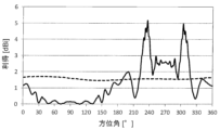
図5は、アンテナ装置1の垂直偏波の水平面内の指向特性の比較図である。すなわち、アレイアンテナ基板10の前方にAM/FM放送用アンテナ素子50が隣接する場合と存在しない場合のアレイアンテナ基板10の垂直偏波の水平面内の利得(dBi)が全方位にわたってどのように変化するかをシミュレーションした特性図である。実線は前者の場合、破線は後者の場合を示す。周波数は、ダイポールアンテナ・アレイ30が動作する5887.5MHzである。図中、方位角90°が前方、方位角270°が後方である。方位角0°~180°がアンテナ装置1の前半分、方位角180°~360°がアンテナ装置1の後半分となる。
なお、図5の各指向特性は、アンテナ装置1のアンテナベース80の位置に、アンテナベース80の代わりに地導体(直径1mの導体板)を設けた場合の例である。
FIG. 5 is a comparison diagram of the directivity characteristics of vertically polarized waves in the horizontal plane of the antenna device 1. That is, how the gain (dBi) in the horizontal plane of vertically polarized waves of the array antenna substrate 10 changes in all directions when the AM/FM broadcasting antenna element 50 is adjacent to the front of the array antenna substrate 10 and when it is not present. It is a characteristic diagram simulating whether The solid line indicates the former case, and the broken line indicates the latter case. The frequency is 5887.5 MHz at which dipole antenna array 30 operates. In the figure, the azimuth angle of 90° is the front, and the azimuth angle of 270° is the rear. The azimuth angle of 0° to 180° corresponds to the front half of the antenna device 1, and the azimuth angle of 180° to 360° corresponds to the rear half of the antenna device 1.
Note that each directional characteristic in FIG. 5 is an example when a ground conductor (a conductive plate with a diameter of 1 m) is provided at the position of the antenna base 80 of the antenna device 1 instead of the antenna base 80.

図6は、アンテナ装置1の主要構成部材(アレイアンテナ基板10、ダイポールアンテナ・アレイ30、容量装荷素子60、ヘリカル素子70)の配置及び寸法関係を示す側面図である。図6に示すように、容量装荷素子60の最後方端とアレイアンテナ基板10の後縁間の前後方向の距離(最も近い距離)は約26.5mmである。また、ダイポールアンテナ・アレイ30がアレイアンテナ基板10の後縁近傍に位置している。そのため、容量装荷素子60の最後方端とダイポールアンテナ・アレイ30との間の前後方向の距離Dは、約26.5mmとなる。これらの距離は、ダイポールアンテナ・アレイ30の動作周波数帯の約1/2波長に相当する。 FIG. 6 is a side view showing the arrangement and dimensional relationship of the main components (array antenna substrate 10, dipole antenna array 30, capacitive loading element 60, helical element 70) of the antenna device 1. As shown in FIG. 6, the distance in the front-rear direction (the closest distance) between the rearmost end of the capacitive loading element 60 and the rear edge of the array antenna substrate 10 is about 26.5 mm. Further, a dipole antenna array 30 is located near the rear edge of the array antenna substrate 10. Therefore, the distance D in the front-rear direction between the rearmost end of the capacitive loading element 60 and the dipole antenna array 30 is approximately 26.5 mm. These distances correspond to approximately 1/2 wavelength of the operating frequency band of dipole antenna array 30.

図5によれば、AM/FM放送用アンテナ素子50が隣接する場合(実線)、アレイアンテナ基板10の水平面における前半分の平均利得は1.7dBiである。また、後半分の平均利得は4.0dBiである。前半分より後半分の平均利得が高い。前半分と後半分の平均利得の差は2.3dBiであった。
これに対し、AM/FM放送用アンテナ素子50が隣接しない場合(破線)、アレイアンテナ基板10の水平面における前半分の平均利得は2.4dBi、後半分の平均利得は3.7dBi、両者の差は1.3dBiであった。
このように、アンテナ装置1の場合、AM/FM放送用アンテナ素子50が隣接しない場合(破線)に比べて、アレイアンテナ基板10の水平面における前半分と後半分の平均利得の差が大きくなった。つまり、アンテナ装置1は、アレイアンテナ基板10の水平面における平均利得が、AM/FM放送用アンテナ素子50が隣接しない場合に比べて高くなった。これは、容量装荷素子60がアレイアンテナ基板10の反射器として機能するためと考えられる。また、これにより、アレイアンテナ基板10の水平面における平均利得は、前半分より後半分の方がいっそう高くなる。
According to FIG. 5, when the AM/FM broadcasting antenna elements 50 are adjacent (solid line), the average gain of the front half of the array antenna substrate 10 in the horizontal plane is 1.7 dBi. Further, the average gain in the latter half is 4.0 dBi. The average gain in the second half is higher than the first half. The difference in average gain between the first half and the second half was 2.3 dBi.
On the other hand, when the AM/FM broadcasting antenna elements 50 are not adjacent to each other (dashed line), the average gain of the front half in the horizontal plane of the array antenna board 10 is 2.4 dBi, and the average gain of the latter half is 3.7 dBi, the difference between the two. was 1.3 dBi.
In this way, in the case of the antenna device 1, the difference in average gain between the front half and the rear half in the horizontal plane of the array antenna board 10 is larger than when the AM/FM broadcasting antenna elements 50 are not adjacent to each other (broken line). . That is, in the antenna device 1, the average gain in the horizontal plane of the array antenna substrate 10 is higher than when the AM/FM broadcasting antenna elements 50 are not adjacent to each other. This is considered to be because the capacitive loading element 60 functions as a reflector for the array antenna substrate 10. Further, as a result, the average gain in the horizontal plane of the array antenna substrate 10 is higher in the rear half than in the front half.

図7は、アンテナ装置1の隣接アンテナの有無による平均利得の差の比較図である。すなわち、距離Dと、アレイアンテナ基板10の水平面における前半分の平均利得と後半分の平均利得との差との関係を示す特性図である。
図7に示すように、距離Dが51.5mm(ダイポールアンテナ・アレイ30の動作周波数帯の約1波長)になっても、アレイアンテナ基板10の水平面における平均利得は、AM/FM放送用アンテナ素子50が存在しない場合に比べて、前半分よりも後半分の方がより高くなっている。
このように、距離Dがダイポールアンテナ・アレイ30の動作周波数帯の約1波長以内であれば、AM/FM放送用アンテナ素子50の容量装荷素子60が、ダイポールアンテナ・アレイ30を備えたアンテナアレイ基板10の反射器として機能することがわかる。
FIG. 7 is a comparison diagram of the difference in average gain between the antenna device 1 and the presence or absence of adjacent antennas. That is, it is a characteristic diagram showing the relationship between the distance D and the difference between the average gain of the front half and the average gain of the rear half in the horizontal plane of the array antenna substrate 10.
As shown in FIG. 7, even if the distance D is 51.5 mm (approximately one wavelength of the operating frequency band of the dipole antenna array 30), the average gain in the horizontal plane of the array antenna substrate 10 is Compared to the case where the element 50 is not present, the rear half is higher than the front half.
In this way, if the distance D is within about one wavelength of the operating frequency band of the dipole antenna array 30, the capacitive loading element 60 of the AM/FM broadcasting antenna element 50 is connected to the antenna array comprising the dipole antenna array 30. It can be seen that the substrate 10 functions as a reflector.

実施の形態1によれば、下記の効果を奏することができる。
(1)アンテナアレイ基板10がダイポールアンテナ・アレイ30を備えることで、アレイでないモノポールアンテナに比べて水平面における平均利得が相対的に高くなる。また、AM/FM放送用アンテナ素子50の容量装荷素子60がアンテナアレイ基板10の反射器として機能することでアレイアンテナ基板10の水平面における平均利得が前半分より後半分の方がより高くなり、指向特性を持たせることができる。
According to the first embodiment, the following effects can be achieved.
(1) Since the antenna array substrate 10 includes the dipole antenna array 30, the average gain in the horizontal plane becomes relatively higher than that of a monopole antenna that is not an array. Furthermore, since the capacitive loading element 60 of the AM/FM broadcasting antenna element 50 functions as a reflector for the antenna array substrate 10, the average gain in the horizontal plane of the array antenna substrate 10 is higher in the rear half than in the front half. It can have directional characteristics.

(2)容量装荷素子60の最後方端とダイポールアンテナ・アレイ30との間の前後方向の距離Dがダイポールアンテナ・アレイ30の動作周波数帯の約1波長以内なので、アレイアンテナ基板10及びAM/FM放送用アンテナ素子50を収容するケース外形を小型化できる。 (2) Since the distance D in the longitudinal direction between the rearmost end of the capacitive loading element 60 and the dipole antenna array 30 is within about one wavelength of the operating frequency band of the dipole antenna array 30, the array antenna substrate 10 and the AM/ The outer shape of the case that houses the FM broadcasting antenna element 50 can be reduced in size.

(3)アレイアンテナ基板10は、誘電体基板20にそれぞれ導体パターンで形成されたダイポールアンテナ・アレイ30と伝送線路40とで構成されるため、同軸構造やスリーブ構造等を用いるよりも材料及び製造コストの低減が可能である。さらに、ダイポールアンテナ・アレイ30や伝送線路40にスルーホールを設けない構造であるため、一層のコスト低減が可能である。 (3) Since the array antenna board 10 is composed of a dipole antenna array 30 and a transmission line 40, which are each formed with a conductor pattern on a dielectric substrate 20, the material and manufacturing method are better than using a coaxial structure or a sleeve structure. Cost reduction is possible. Furthermore, since the structure does not include through holes in the dipole antenna array 30 or the transmission line 40, further cost reduction is possible.

<実施の形態2>
図8は実施の形態2に係るアンテナ装置2の前方に向かって左側の側面図、図9は同じく前方に向かって右側の側面図である。図8における前後、上下方向は図1と同じである。アンテナ装置2では、第1のアンテナとしてスリーブアンテナ90を用いた点がアンテナ装置1と異なる。スリーブアンテナ90は、同軸線路91(外側導体93を含む)の上端から中心導体92をスリーブアンテナ90の動作周波数帯(例えば共振周波数帯)の1/4波長上方に伸長させている。また、同軸線路91の外周絶縁体の外側に、外側導体93をスリーブアンテナ90の動作周波数帯の1/4波長下方に折り返している。スリーブアンテナ90以外の構成は、実施の形態1と同様である。
<Embodiment 2>
FIG. 8 is a left side view of the antenna device 2 according to the second embodiment when viewed from the front, and FIG. 9 is a right side view of the antenna device 2 when viewed from the front. The front-rear and up-down directions in FIG. 8 are the same as in FIG. 1. Antenna device 2 differs from antenna device 1 in that a sleeve antenna 90 is used as the first antenna. The sleeve antenna 90 has a center conductor 92 extending from the upper end of a coaxial line 91 (including an outer conductor 93) above a quarter wavelength of the operating frequency band (eg, resonant frequency band) of the sleeve antenna 90. Further, on the outside of the outer peripheral insulator of the coaxial line 91, an outer conductor 93 is folded back to a position 1/4 wavelength below the operating frequency band of the sleeve antenna 90. The configuration other than the sleeve antenna 90 is the same as that of the first embodiment.

図10は、アンテナ装置2の垂直偏波の水平面内の指向特性の比較図である。すなわち、スリーブアンテナ90の前方にAM/FM放送用アンテナ素子50が隣接する場合と存在しない場合のスリーブアンテナ90の垂直偏波の水平面内の利得(dBi)が全方位にわたってどのように変化するかをシミュレーションした特性図である。実線は前者の場合、破線は後者の場合を示す。周波数は、スリーブアンテナ90が動作する5887.5MHzである。図10において方位角90°が前方、方位角270°が後方である。方位角0°~180°がアンテナ装置2の前半分となり、方位角180°~360°がアンテナ装置2の後半分となる。
なお、図10の各指向特性は、アンテナ装置2のアンテナベース80の位置に、アンテナベース80の代わりに地導体(直径1mの導体板)を設けた場合の例である。
FIG. 10 is a comparison diagram of the directivity characteristics of the vertically polarized waves of the antenna device 2 in the horizontal plane. That is, how the gain (dBi) in the horizontal plane of the vertically polarized wave of the sleeve antenna 90 changes in all directions when the AM/FM broadcasting antenna element 50 is adjacent to the front of the sleeve antenna 90 and when it is not present. It is a characteristic diagram simulating. The solid line indicates the former case, and the broken line indicates the latter case. The frequency is 5887.5 MHz at which the sleeve antenna 90 operates. In FIG. 10, the azimuth angle of 90° is the front, and the azimuth angle of 270° is the rear. The azimuth angle of 0° to 180° corresponds to the front half of the antenna device 2, and the azimuth angle of 180° to 360° corresponds to the rear half of the antenna device 2.
Note that each directional characteristic in FIG. 10 is an example when a ground conductor (a conductive plate with a diameter of 1 m) is provided at the position of the antenna base 80 of the antenna device 2 instead of the antenna base 80.

図11は図10の指向特性図を求めたときの、主要構成部材(スリーブアンテナ90、容量装荷素子60、ヘリカル素子70)の配置及び寸法関係を示す側面図である。図11に示すように、容量装荷素子60の最後方端とスリーブアンテナ90の外周間の前後方向の距離は、15.0mmである。 FIG. 11 is a side view showing the arrangement and dimensional relationship of the main components (sleeve antenna 90, capacitive loading element 60, helical element 70) when obtaining the directivity diagram of FIG. 10. As shown in FIG. 11, the distance in the front-rear direction between the rearmost end of the capacitive loading element 60 and the outer periphery of the sleeve antenna 90 is 15.0 mm.

アンテナ装置2の場合(実線)、スリーブアンテナ90の水平面における前半分の平均利得は0.5dBi、後半分の平均利得は3.4dBiであり、両者の差は2.9dBiであった。これに対し、AM/FM放送用アンテナ素子50が隣接しない場合(破線)、スリーブアンテナ90の水平面における前半分の平均利得は2.6dBi、後半分の平均利得は2.6dBiであり、両者の差は無かった。
このように、アンテナ装置2は、スリーブアンテナ90の水平面における平均利得が、図28に示すモノポールアンテナの水平面における平均利得よりも高い。そして、AM/FM放送用アンテナ素子50が存在しない場合に比べて、スリーブアンテナ90の水平面における前半分と後半分の平均利得の差が大きい。
また、スリーブアンテナ90自体がモノポールアンテナよりも高利得であり、しかも隣接する容量装荷素子60が反射器として機能するので、スリーブアンテナ90の水平面における平均利得は、前半分より後半分の方が高くなる。
In the case of the antenna device 2 (solid line), the average gain of the front half of the sleeve antenna 90 in the horizontal plane was 0.5 dBi, the average gain of the rear half was 3.4 dBi, and the difference between the two was 2.9 dBi. On the other hand, when the AM/FM broadcasting antenna elements 50 are not adjacent to each other (dashed line), the average gain of the front half of the sleeve antenna 90 in the horizontal plane is 2.6 dBi, and the average gain of the rear half is 2.6 dBi. There was no difference.
Thus, in the antenna device 2, the average gain of the sleeve antenna 90 in the horizontal plane is higher than the average gain of the monopole antenna shown in FIG. 28 in the horizontal plane. Furthermore, the difference in average gain between the front half and the rear half of the sleeve antenna 90 in the horizontal plane is larger than when the AM/FM broadcasting antenna element 50 is not present.
Further, since the sleeve antenna 90 itself has a higher gain than a monopole antenna, and the adjacent capacitive loading element 60 functions as a reflector, the average gain in the horizontal plane of the sleeve antenna 90 is higher in the rear half than in the front half. It gets expensive.

図11に示したように容量装荷素子60の最後方端とスリーブアンテナ90の外周間の前後方向の距離が15.0mmであり、スリーブアンテナ90の動作周波数帯の1/2波長よりも短い。この前後方向の距離がスリーブアンテナ90の動作周波数帯の約1波長以内であれば、容量装荷素子60がスリーブアンテナ90の反射器として機能するので、スリーブアンテナ90の水平面における平均利得は前半分よりも後半分の方がより高くなる。 As shown in FIG. 11, the distance in the front-rear direction between the rearmost end of capacitive loading element 60 and the outer periphery of sleeve antenna 90 is 15.0 mm, which is shorter than 1/2 wavelength of the operating frequency band of sleeve antenna 90. If this longitudinal distance is within about one wavelength of the operating frequency band of the sleeve antenna 90, the capacitive loading element 60 functions as a reflector for the sleeve antenna 90, so that the average gain in the horizontal plane of the sleeve antenna 90 is higher than that of the front half. is also higher in the second half.

<実施の形態3>
図12は実施の形態3に係るアンテナ装置3の前方に向かって左側の側面図、図13は同じく前方に向かって右側の側面図である。図12における前後、上下方向は図1と同じである。アンテナ装置3は、垂直偏波用の第1のアンテナとしてコリニアアレイアンテナ95を用いた点がアンテナ装置1,2と異なる。コリニアアレイアンテナ95は、例えば垂直に設置した動作周波数帯の1/4波長のモノポールアンテナのエレメントの上端に、位相が同相になるようにした数本の動作周波数帯の1/2波長のエレメントを直列接続したものである。
<Embodiment 3>
FIG. 12 is a left side view of the antenna device 3 according to the third embodiment when viewed from the front, and FIG. 13 is a right side view of the antenna device 3 when viewed from the front. The front-rear and up-down directions in FIG. 12 are the same as in FIG. 1. Antenna device 3 differs from antenna devices 1 and 2 in that a collinear array antenna 95 is used as the first antenna for vertically polarized waves. The collinear array antenna 95 includes, for example, several 1/2 wavelength elements of the operating frequency band whose phases are in the same phase on the upper end of a vertically installed monopole antenna element of 1/4 wavelength of the operating frequency band. are connected in series.

図14はアンテナ装置3の垂直偏波の水平面内の指向特性の比較図である。すなわち、コリニアアレイアンテナ95の前方にAM/FM放送用アンテナ素子50の容量装荷素子60が隣接する場合と存在しない場合のコリニアアレイアンテナ95の垂直偏波の水平面内の利得(dBi)が全方位にわたってどのように変化するかをシミュレーションした特性図である。実線は前者の場合、破線は後者の場合を示す。周波数は、コリニアアレイアンテナ95が動作する5887.5MHzである。図14において方位角90°が前方、方位角270°が後方である。方位角0°~180°がアンテナ装置3の前半分となり、方位角180°~360°がアンテナ装置3の後半分となる。
なお、図14の各指向特性は、アンテナ装置3のアンテナベース80の位置に、アンテナベース80の代わりに地導体(直径1mの導体板)を設けた場合の例である。
FIG. 14 is a comparison diagram of the directivity characteristics of vertically polarized waves in the horizontal plane of the antenna device 3. That is, the gain (dBi) in the horizontal plane of the vertically polarized wave of the collinear array antenna 95 when the capacitive loading element 60 of the AM/FM broadcasting antenna element 50 is adjacent to the front of the collinear array antenna 95 and when it does not exist is omnidirectional. It is a characteristic diagram simulating how it changes over time. The solid line indicates the former case, and the broken line indicates the latter case. The frequency is 5887.5 MHz at which the collinear array antenna 95 operates. In FIG. 14, the azimuth angle of 90° is the front, and the azimuth angle of 270° is the rear. The azimuth angle of 0° to 180° corresponds to the front half of the antenna device 3, and the azimuth angle of 180° to 360° corresponds to the rear half of the antenna device 3.
Note that each directional characteristic in FIG. 14 is an example when a ground conductor (a conductive plate with a diameter of 1 m) is provided at the position of the antenna base 80 of the antenna device 3 instead of the antenna base 80.

図15はアンテナ装置3の主要構成部材(コリニアアレイアンテナ95、容量装荷素子60、ヘリカル素子70)の配置及び寸法関係を示す側面図である。図15に示すように、容量装荷素子60の最後方端とコリニアアレイアンテナ95間の前後方向の距離は、15.0mmである。 FIG. 15 is a side view showing the arrangement and dimensional relationship of the main components (collinear array antenna 95, capacitive loading element 60, helical element 70) of the antenna device 3. As shown in FIG. 15, the distance in the front-rear direction between the rearmost end of the capacitive loading element 60 and the collinear array antenna 95 is 15.0 mm.

アンテナ装置3の場合(実線)、コリニアアレイアンテナ95の水平面における前半分の平均利得は1.2dBi、後半分の平均利得は2.2dBiであり、両者の差は1.0dBiであった。これに対し、容量装荷素子60が隣接しない場合(破線)、コリニアアレイアンテナ95の水平面における前半分の平均利得は2.0dBi、後半分の平均利得は2.0dBiであり、両者の差は無かった。
このように、アンテナ装置3の場合、コリニアアレイアンテナ95の水平面における平均利得が、図28に示すモノポールアンテナの水平面における平均利得よりも高い。そして、容量装荷素子60が隣接しない場合に比べて、コリニアアレイアンテナ95の水平面における前半分と後半分の平均利得の差は大きい。
また、アンテナ装置3は、水平面における平均利得がモノポールアンテナに比べて高利得となり、容量装荷素子60が存在しない場合に比べてコリニアアレイアンテナ95の水平面における平均利得は前半分より後半分の方が高くなる。
In the case of the antenna device 3 (solid line), the average gain of the front half of the collinear array antenna 95 in the horizontal plane was 1.2 dBi, the average gain of the rear half was 2.2 dBi, and the difference between the two was 1.0 dBi. On the other hand, when the capacitive loading elements 60 are not adjacent to each other (broken line), the average gain of the front half of the collinear array antenna 95 in the horizontal plane is 2.0 dBi, and the average gain of the rear half is 2.0 dBi, and there is no difference between the two. Ta.
Thus, in the case of the antenna device 3, the average gain of the collinear array antenna 95 in the horizontal plane is higher than the average gain of the monopole antenna shown in FIG. 28 in the horizontal plane. The difference in average gain between the front half and the rear half of the collinear array antenna 95 in the horizontal plane is larger than when the capacitive loading elements 60 are not adjacent to each other.
Furthermore, the average gain in the horizontal plane of the antenna device 3 is higher than that of a monopole antenna, and the average gain in the horizontal plane of the collinear array antenna 95 is higher in the rear half than in the front half compared to the case where the capacitive loading element 60 is not present. becomes higher.

図15に示したように容量装荷素子60の最後方端とコリニアアレイアンテナ95の外周間の前後方向の距離が15.0mmで、コリニアアレイアンテナ95の動作周波数帯の1/2波長よりも短い。この前後方向の距離がコリニアアレイアンテナ95の動作周波数帯の約1波長以内であれば、容量装荷素子60が反射器として機能するので、コリニアアレイアンテナ95の水平面における平均利得は前半分よりも後半分の方がより高くなる。 As shown in FIG. 15, the distance in the longitudinal direction between the rearmost end of the capacitive loading element 60 and the outer periphery of the collinear array antenna 95 is 15.0 mm, which is shorter than 1/2 wavelength of the operating frequency band of the collinear array antenna 95. . If this distance in the front-rear direction is within about one wavelength of the operating frequency band of the collinear array antenna 95, the capacitive loading element 60 functions as a reflector, so the average gain in the horizontal plane of the collinear array antenna 95 is in the second half rather than in the front half. minutes will be more expensive.

<実施の形態4>
図16は実施の形態4に係るアンテナ装置4の前方に向かって左側の側面図、図17は同じく前方に向かって右側の側面図である。図18は同じく上方から見た平面図、図19は同じく右側後上方から見た斜視図である。図16における前後、上下方向は図1と同じである。アンテナ装置4は、AM/FM放送用アンテナ素子50の構成と、パッチアンテナ100を備えている点がアンテナ装置1と異なる。 アンテナ装置4のAM/FM放送用アンテナ素子50は、容量装荷素子60Aが、頂部が無く、下縁で左右方向に対向する分割体同士が接続され、かつ前後方向に分かれて配置されている。パッチアンテナ100は、容量装荷素子60Aの下方に配置されている。容量装荷素子60Aは、山形の斜面を底部で連結した形状の導体板からなる分割体61,62,63,64の隣り合うもの同士をフィルタ65で連結した構成である。フィルタ65はAM/FM放送の周波数帯では低インピーダンスで、アレイアンテナ基板10及びパッチアンテナ100のそれぞれの動作周波数帯では高インピーダンスとなる。つまり、AM/FM放送の周波数帯では、分割体61,62,63,64が相互接続されて一つの大きな導体とみなせる。パッチアンテナ100は、図18及び図19に示すように、上面に放射電極101を有し、上向きの指向特性を有する。
<Embodiment 4>
FIG. 16 is a side view of the left side of the antenna device 4 according to the fourth embodiment when facing the front, and FIG. 17 is a side view of the right side of the antenna device 4 when facing the front. FIG. 18 is a plan view similarly seen from above, and FIG. 19 is a perspective view similarly seen from the right rear upper side. The front-rear and up-down directions in FIG. 16 are the same as in FIG. 1. The antenna device 4 differs from the antenna device 1 in that it has a configuration of an AM/FM broadcasting antenna element 50 and a patch antenna 100. In the AM/FM broadcasting antenna element 50 of the antenna device 4, the capacitive loading element 60A has no top, the divided bodies facing each other in the left-right direction are connected at the lower edge, and are arranged separately in the front-back direction. Patch antenna 100 is arranged below capacitive loading element 60A. The capacitive loading element 60A has a configuration in which adjacent divided bodies 61, 62, 63, and 64 each made of a conductor plate having a shape of a chevron connected at its bottom are connected by a filter 65. The filter 65 has a low impedance in the frequency band of AM/FM broadcasting, and has a high impedance in the operating frequency bands of the array antenna board 10 and the patch antenna 100. That is, in the frequency band of AM/FM broadcasting, the divided bodies 61, 62, 63, and 64 are interconnected and can be regarded as one large conductor. As shown in FIGS. 18 and 19, the patch antenna 100 has a radiation electrode 101 on its upper surface and has upward directivity.

図20はアンテナ装置4の垂直偏波の水平面内の指向特性の比較図である。すなわち、アレイアンテナ基板10の前方に、分割構造の容量装荷素子60Aを有するAM/FM放送用アンテナ素子50が隣接する場合と隣接しない場合のアレイアンテナ基板10の垂直偏波の水平面内の利得(dBi)が全方位にわたってどのように変化するかをシミュレーションした特性図である。実線は前者の場合、破線は後者の場合を示す。周波数は、アレイアンテナ基板10のダイポールアンテナ・アレイ30が動作する5887.5MHzである。図20において方位角90°が前方、方位角270°が後方である。方位角0°~180°がアンテナ装置4の前半分となり、方位角180°~360°がアンテナ装置4の後半分となる。なお、図20の各指向特性は、アンテナ装置4のアンテナベース80の位置に、アンテナベース80の代わりに地導体(直径1mの導体板)を設けた場合の例である。 FIG. 20 is a comparison diagram of the directivity characteristics of the vertically polarized waves of the antenna device 4 in the horizontal plane. That is, the gain in the horizontal plane of the vertically polarized wave of the array antenna substrate 10 when the AM/FM broadcasting antenna element 50 having the capacitive loading element 60A having a split structure is adjacent to the front of the array antenna substrate 10 and when it is not adjacent to the antenna element 50 for vertical polarization ( dBi) is a characteristic diagram simulating how it changes over all directions. The solid line indicates the former case, and the broken line indicates the latter case. The frequency is 5887.5 MHz at which the dipole antenna array 30 of the array antenna board 10 operates. In FIG. 20, the azimuth angle of 90° is the front, and the azimuth angle of 270° is the rear. The azimuth angle of 0° to 180° corresponds to the front half of the antenna device 4, and the azimuth angle of 180° to 360° corresponds to the rear half of the antenna device 4. Note that each directional characteristic in FIG. 20 is an example when a ground conductor (a conductive plate with a diameter of 1 m) is provided at the position of the antenna base 80 of the antenna device 4 instead of the antenna base 80.

図21はアンテナ装置4の主要構成部材(アレイアンテナ基板10、容量装荷素子60A、ヘリカル素子70、パッチアンテナ100)の配置及び寸法関係を示す側面図である。図21に示すように、容量装荷素子60Aの最後方端とアレイアンテナ基板10の後縁間の前後方向の距離は26.5mmである。また、ダイポールアンテナ・アレイ30はアレイアンテナ基板10の後縁近傍に位置していることから、容量装荷素子60Aの最後方端とダイポールアンテナ・アレイ30との間の前後方向の距離Dは約26.5mmである。これらの距離はダイポールアンテナ・アレイ30の動作周波数帯の約1/2波長に相当する。 FIG. 21 is a side view showing the arrangement and dimensional relationship of the main components of the antenna device 4 (array antenna substrate 10, capacitive loading element 60A, helical element 70, patch antenna 100). As shown in FIG. 21, the distance in the front-rear direction between the rearmost end of the capacitive loading element 60A and the rear edge of the array antenna substrate 10 is 26.5 mm. Furthermore, since the dipole antenna array 30 is located near the rear edge of the array antenna substrate 10, the distance D in the front-rear direction between the rearmost end of the capacitive loading element 60A and the dipole antenna array 30 is approximately 26 It is .5mm. These distances correspond to approximately 1/2 wavelength of the operating frequency band of dipole antenna array 30.

図20の指向特性は、図21に示したように容量装荷素子60Aの最後方端とダイポールアンテナ・アレイ30との間の前後方向の距離Dがダイポールアンテナ・アレイ30の動作周波数帯の約1/2波長の場合である。距離Dがダイポールアンテナ・アレイ30の動作周波数帯の約1波長以内であれば、AM/FM放送用アンテナ素子50が存在しない場合に比べて容量装荷素子60Aが反射器として機能する。そのため、アレイアンテナ基板10の水平面における平均利得は、前半分よりも後半分の方がより高くなる。 In the directional characteristics of FIG. 20, as shown in FIG. /2 wavelength. If distance D is within about one wavelength of the operating frequency band of dipole antenna array 30, capacitive loading element 60A functions as a reflector compared to the case where AM/FM broadcasting antenna element 50 is not present. Therefore, the average gain in the horizontal plane of the array antenna substrate 10 is higher in the rear half than in the front half.

図20によれば、アンテナ装置4の場合(実線)、アレイアンテナ基板10の水平面における前半分の平均利得は1.3dBi、後半分の平均利得は3.3dBiであり、両者の差は2.0dBiであった。これに対し、AM/FM放送用アンテナ素子50が隣接しない場合(破線)、アレイアンテナ基板10の水平面における前半分の平均利得は2.8dBi、後半分の平均利得は3.7dBiであり、両者の差は0.9dBiであった。
このように、アンテナ装置4は、AM/FM放送用アンテナ素子50が隣接しない場合に比べてアレイアンテナ基板10の水平面における前半分と後半分の平均利得の差は大きくなっている。アンテナ装置4の場合は、水平面における平均利得がモノポールアンテナに比べて高利得となり、AM/FM放送用アンテナ素子50が隣接しない場合に比べて容量装荷素子60Aが反射器として働くことでアレイアンテナ基板10の水平面における平均利得は前半分より後半分の方がより高くなる。
According to FIG. 20, in the case of the antenna device 4 (solid line), the average gain of the front half of the array antenna substrate 10 in the horizontal plane is 1.3 dBi, and the average gain of the rear half is 3.3 dBi, and the difference between the two is 2. It was 0dBi. On the other hand, when the AM/FM broadcasting antenna elements 50 are not adjacent to each other (dashed line), the average gain of the front half in the horizontal plane of the array antenna board 10 is 2.8 dBi, the average gain of the rear half is 3.7 dBi, and both The difference was 0.9 dBi.
In this way, in the antenna device 4, the difference in average gain between the front half and the rear half in the horizontal plane of the array antenna substrate 10 is larger than when the AM/FM broadcasting antenna elements 50 are not adjacent to each other. In the case of the antenna device 4, the average gain in the horizontal plane is higher than that of a monopole antenna, and compared to the case where the AM/FM broadcasting antenna elements 50 are not adjacent, the capacitive loading element 60A acts as a reflector, resulting in an array antenna. The average gain in the horizontal plane of the substrate 10 is higher in the rear half than in the front half.

図22は、アンテナ装置4において容量装荷素子60Aの前後方向の分割の有無によるパッチアンテナの周波数と軸比(dB)との関係を示す特性図である。また、図23は、アンテナ装置4において容量装荷素子の前後方向の分割の有無によるパッチアンテナの仰角10°における周波数と円偏波の平均利得との関係を示す特性図である。図22及び図23において、「分割無し」は、実施の形態1の容量装荷素子60に相当する。「4分割」は本実施の形態の容量装荷素子60Aに相当する。「2分割」及び「3分割」は容量装荷素子をそれぞれ前後方向に2分割及び3分割した場合に相当する。 FIG. 22 is a characteristic diagram showing the relationship between the frequency and the axial ratio (dB) of the patch antenna depending on whether or not the capacitive loading element 60A is divided in the front-back direction in the antenna device 4. Further, FIG. 23 is a characteristic diagram showing the relationship between the frequency and the average gain of circularly polarized waves at an elevation angle of 10° of the patch antenna depending on whether or not the capacitive loading element is divided in the front-back direction in the antenna device 4. In FIGS. 22 and 23, "no division" corresponds to the capacitive loading element 60 of the first embodiment. "Four division" corresponds to the capacitive loading element 60A of this embodiment. "Dividing into two" and "dividing into three" correspond to the case where the capacitive loading element is divided into two and three parts in the front-rear direction, respectively.

図22から明らかな通り、容量装荷素子の分割数を多くするほど軸比(dB)が小さくなり、パッチアンテナ100の指向特性が改善される。また、容量装荷素子60Aの各々の分割体61~64の前後方向の大きさがパッチアンテナ100の動作周波数帯の波長に比べて小さくなると(つまり分割数が多くなると)、容量装荷素子60Aの各分割体61~64によるパッチアンテナ100への悪影響(平均利得の低下等)を低減可能となる。このため、図23に示すように、容量装荷素子を分割しない場合に比べて、低仰角(仰角10°)における平均利得が向上する。このように、容量装荷素子が前後方向に分かれて配置されていると、円偏波における軸比が低くなり、パッチアンテナ100で円偏波の送受信が良好になる。 As is clear from FIG. 22, as the number of divisions of the capacitive loading element increases, the axial ratio (dB) becomes smaller, and the directivity characteristics of the patch antenna 100 are improved. Furthermore, when the longitudinal size of each of the divided bodies 61 to 64 of the capacitive loading element 60A becomes smaller than the wavelength of the operating frequency band of the patch antenna 100 (that is, when the number of divisions increases), each of the capacitive loading element 60A becomes smaller than the wavelength of the operating frequency band of the patch antenna 100. It is possible to reduce the adverse effects (such as a decrease in average gain) on the patch antenna 100 due to the dividing bodies 61 to 64. Therefore, as shown in FIG. 23, the average gain at a low elevation angle (elevation angle of 10°) is improved compared to the case where the capacitive loading element is not divided. In this way, when the capacitive loading elements are arranged separately in the front-back direction, the axial ratio of circularly polarized waves becomes low, and the patch antenna 100 can transmit and receive circularly polarized waves well.

<実施の形態5>
図24は実施の形態5に係るアンテナ装置5の前方に向かって左側の側面図、図25は同じく前方に向かって右側の側面図である。アンテナ装置5は、各ダイポールアンテナ31に対応させて前方に向かって右側の側面のみに導波器35を設けたアレイアンテナ基板10Aを備える点がアンテナ装置4と異なる。導波器35はダイポールアンテナ31と平行に所定距離だけ離れて誘電体基板20に設けられた導体パターンである。その他の構成は実施の形態4と同様である。
<Embodiment 5>
FIG. 24 is a left side view of the antenna device 5 according to the fifth embodiment when viewed from the front, and FIG. 25 is a right side view of the antenna device 5 when viewed from the front. The antenna device 5 differs from the antenna device 4 in that it includes an array antenna substrate 10A in which a waveguide 35 is provided only on the right side surface when facing forward in correspondence with each dipole antenna 31. The waveguide 35 is a conductor pattern provided on the dielectric substrate 20 parallel to the dipole antenna 31 and separated from it by a predetermined distance. The other configurations are the same as in the fourth embodiment.

図26はアンテナ装置5の垂直偏波の水平面内の指向特性の比較図である。すなわち、アレイアンテナ基板10Aの前方に、分割構造の容量装荷素子60Aを有するAM/FM放送用アンテナ素子50が隣接する場合と存在しない場合のアレイアンテナ基板10の垂直偏波の水平面内の利得(dBi)が全方位にわたってどのように変化するかをシミュレーションした特性図である。実線は前者の場合、破線は後者の場合を示す。周波数は5887.5MHzである。図26において方位角90°が前方、方位角270°が後方である。方位角0°~180°がアンテナ装置5の前半分となり、方位角180°~360°がアンテナ装置6の後半分となる。なお、図26の各指向特性は、アンテナ装置5のアンテナベース80の位置に、アンテナベース80の代わりに地導体(直径1mの導体板)を設けた場合の例である。 FIG. 26 is a comparison diagram of the directivity characteristics of the vertically polarized waves of the antenna device 5 in the horizontal plane. That is, the gain in the horizontal plane of the vertically polarized wave of the array antenna substrate 10 when the AM/FM broadcasting antenna element 50 having the capacitive loading element 60A having a split structure is adjacent to the front of the array antenna substrate 10A and when it is not present ( dBi) is a characteristic diagram simulating how it changes over all directions. The solid line indicates the former case, and the broken line indicates the latter case. The frequency is 5887.5MHz. In FIG. 26, the azimuth angle of 90° is the front, and the azimuth angle of 270° is the rear. The azimuth angle of 0° to 180° corresponds to the front half of the antenna device 5, and the azimuth angle of 180° to 360° corresponds to the rear half of the antenna device 6. Note that each directional characteristic in FIG. 26 is an example when a ground conductor (a conductive plate with a diameter of 1 m) is provided at the position of the antenna base 80 of the antenna device 5 instead of the antenna base 80.

図27はアンテナ装置5の主要構成部材(アレイアンテナ基板10A、容量装荷素子60A、ヘリカル素子70、パッチアンテナ100)の配置及び寸法関係を示す側面図である。図27に示すように、容量装荷素子60Aの最後方端とアレイアンテナ基板10Aの後縁間の前後方向の距離は30.5mmである。しかし、ダイポールアンテナ・アレイ30のアレイアンテナ基板10A前縁からの位置関係は実施の形態4のアレイアンテナ基板10と同じなので、容量装荷素子60Aの最後方端とダイポールアンテナ・アレイ30との間の前後方向の距離Dは約26.5mmである。この距離Dはダイポールアンテナ・アレイ30の動作周波数帯の約1/2波長に相当する。
図26の指向特性図は、距離Dがダイポールアンテナ・アレイ30の動作周波数帯の約1/2波長の場合である。距離Dがダイポールアンテナ・アレイ30の動作周波数帯の約1波長以内であれば、AM/FM放送用アンテナ素子50が存在しない場合に比べて容量装荷素子60Aが反射器として機能する。そのため、アレイアンテナ基板10Aの水平面における平均利得は、前半分よりも後半分の方がより高くなる。
FIG. 27 is a side view showing the arrangement and dimensional relationship of the main components (array antenna substrate 10A, capacitive loading element 60A, helical element 70, patch antenna 100) of the antenna device 5. As shown in FIG. 27, the distance in the front-rear direction between the rearmost end of capacitive loading element 60A and the rear edge of array antenna substrate 10A is 30.5 mm. However, since the positional relationship of the dipole antenna array 30 from the front edge of the array antenna substrate 10A is the same as that of the array antenna substrate 10 of the fourth embodiment, the distance between the rearmost end of the capacitive loading element 60A and the dipole antenna array 30 is The distance D in the front-rear direction is approximately 26.5 mm. This distance D corresponds to approximately 1/2 wavelength of the operating frequency band of the dipole antenna array 30.
The directional characteristic diagram in FIG. 26 is for the case where the distance D is approximately 1/2 wavelength of the operating frequency band of the dipole antenna array 30. If distance D is within about one wavelength of the operating frequency band of dipole antenna array 30, capacitive loading element 60A functions as a reflector compared to the case where AM/FM broadcasting antenna element 50 is not present. Therefore, the average gain in the horizontal plane of the array antenna substrate 10A is higher in the rear half than in the front half.

アンテナ装置5の場合、アレイアンテナ基板10Aの水平面における前方の平均利得は0.7dBi、後方の平均利得は3.9dBiであり、両者の差は3.2dBiであった。これに対して、AM/FM放送用アンテナ素子50の容量装荷素子60Aが存在しない場合、アレイアンテナ基板10Aの水平面における前方の平均利得は2.3dBi、後方の平均利得は4.3dBiであり、両者の差は2.0dBiであった。 In the case of the antenna device 5, the average gain in the front of the array antenna substrate 10A in the horizontal plane was 0.7 dBi, the average gain in the rear was 3.9 dBi, and the difference between the two was 3.2 dBi. On the other hand, when the capacitive loading element 60A of the AM/FM broadcasting antenna element 50 is not present, the average gain in the front of the array antenna board 10A in the horizontal plane is 2.3 dBi, and the average gain in the rear is 4.3 dBi. The difference between the two was 2.0 dBi.

このように、アンテナ装置5は、水平面における平均利得が図28に示すモノポールアンテナの水平面における平均利得よりも高い。そして、容量装荷素子60Aが存在しない場合に比べて、アレイアンテナ基板10Aの水平面における前半分と後半分の平均利得の差は大きくなっている。つまり、アンテナ装置5の場合は、水平面における平均利得がモノポールアンテナに比べて高利得となり、容量装荷素子60Aが反射器として機能することでアレイアンテナ基板10Aの水平面における平均利得は前半分より後半分の方がより高くなる。さらに、アレイアンテナ基板10Aが導波器35を有しているため、後半分の平均利得は実施の形態4よりも高くなる。 In this way, the antenna device 5 has a higher average gain in the horizontal plane than the average gain in the horizontal plane of the monopole antenna shown in FIG. The difference in average gain between the front half and the rear half in the horizontal plane of the array antenna substrate 10A is larger than in the case where the capacitive loading element 60A is not present. In other words, in the case of the antenna device 5, the average gain in the horizontal plane is higher than that of a monopole antenna, and because the capacitive loading element 60A functions as a reflector, the average gain in the horizontal plane of the array antenna board 10A is higher than the first half. minutes will be more expensive. Furthermore, since the array antenna substrate 10A includes the waveguide 35, the average gain in the latter half is higher than in the fourth embodiment.

なお、図25に示すように、アンテナ装置5ではアレイアンテナ基板10Aの前方に向かって右側の側面のみに導波器35を設けているが、アレイアンテナ基板10Aの左側の側面のみに導波器を設けてもよいし、両面に導波器を設けてもよい。いずれの場合でも、指向特性が他の実施の形態例より高まる点は共通である。 As shown in FIG. 25, in the antenna device 5, the waveguide 35 is provided only on the right side surface when facing the front of the array antenna substrate 10A, but the waveguide 35 is provided only on the left side surface of the array antenna substrate 10A. may be provided, or waveguides may be provided on both sides. In either case, the common point is that the directional characteristics are higher than those of other embodiments.

<実施の形態6>
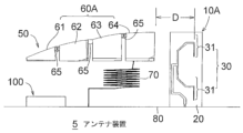
図29は実施の形態6に係るアンテナ装置6の前方に向かって左側の側面図、図30は同じく左側後上方から見た斜視図である。前後、上下方向は図1と同じである。アンテナ装置6は、第1のアンテナとしてV2X通信用のコリニアアレイアンテナ95を用い、第2のアンテナとして実施の形態4で説明した分割構造の容量装荷素子60A及びヘリカル素子70を有するAM/FM放送用アンテナ素子50を用いている。コリニアアレイアンテナ95は、容量装荷素子60Aの後方に隣接される。アンテナ装置6は、車両への取付時には、図示しない電波透過性のアンテナケースに収容される。
<Embodiment 6>
FIG. 29 is a side view of the left side of the antenna device 6 according to the sixth embodiment when viewed from the front, and FIG. 30 is a perspective view of the antenna device 6 viewed from the rear and upper side of the left side. The front-rear and up-down directions are the same as in FIG. The antenna device 6 uses a collinear array antenna 95 for V2X communication as a first antenna, and has a split-structure capacitive loading element 60A and a helical element 70 described in Embodiment 4 as a second antenna. antenna element 50 is used. Collinear array antenna 95 is adjacent to the rear of capacitive loading element 60A. When attached to a vehicle, the antenna device 6 is housed in a radio wave transparent antenna case (not shown).

容量装荷素子60Aは、断面山型に成形された樹脂製のアンテナホルダー670の天頂面に固定される。ヘリカル素子70は、アンテナホルダー670の下方のヘリカルホルダー671に支持される。アンテナホルダー670は、それぞれ左右に拡がる一対の前方脚部672,673と一対の後方脚部674,675を介してアンテナベース80にねじ止め固定される。なお、ヘリカル素子70は容量装荷素子60Aの幅方向(左右方向)のいずれかにオフセットしているが、幅方向の略中央にあってもよい。 The capacitive loading element 60A is fixed to the zenith surface of a resin antenna holder 670 having a chevron-shaped cross section. The helical element 70 is supported by a helical holder 671 below the antenna holder 670. The antenna holder 670 is screwed and fixed to the antenna base 80 via a pair of front legs 672, 673 and a pair of rear legs 674, 675, which extend left and right, respectively. Note that although the helical element 70 is offset in either the width direction (horizontal direction) of the capacitive loading element 60A, it may be located approximately at the center in the width direction.

コリニアアレイアンテナ95は、線状又は棒状のエレメントで構成される。コリニアアレイアンテナ95は、アンテナ装置6を車体に取り付けた場合、車体が地導体板として機能し、V2X通信に適合する垂直偏波用となるように、水平面(重力の方向と直角を成す面)に対して略垂直(つまり略鉛直方向)に配置される。実施の形態6では、それぞれ断面多角形の棒状のエレメントで、第1直線部951、環状部952及び第2直線部953でコリニアアレイアンテナ95を構成した。 The collinear array antenna 95 is composed of linear or rod-shaped elements. The collinear array antenna 95 is installed in a horizontal plane (a plane perpendicular to the direction of gravity) so that when the antenna device 6 is attached to the vehicle body, the vehicle body functions as a ground conductor plate and is used for vertically polarized waves compatible with V2X communication. (in other words, in a substantially vertical direction). In the sixth embodiment, a collinear array antenna 95 is configured by a first linear portion 951, an annular portion 952, and a second linear portion 953, each of which is a rod-shaped element with a polygonal cross section.

第1直線部951は、アンテナベース80に対して第1の傾斜角(例えば90度)で上方に延伸する。第1直線部951の基端は給電部である。第2直線部953は、第1直線部951に対して第2の傾斜角(90度+θ)で前方に傾斜する。第2直線部953は、容量装荷素子60Aと同じ高さの部分でその先端が折曲している。折曲した部分の長さは、折曲していることでコリニアアレイアンテナ95のアンテナ性能に影響が無い長さに調整されている。つまり、第2直線部953をその先端の部分及び第1直線部951と同じ傾斜で一直線に伸ばすと、第2直線部953が全て直線状であるときと長さは同じになる。
環状部952は、第1直線部951の先端と第2直線部953の基端との間に存在する螺旋状のエレメントであり、第1直線部951と第2直線部953の位相を合致させるために存在する。
The first straight portion 951 extends upward at a first inclination angle (for example, 90 degrees) with respect to the antenna base 80 . The base end of the first straight portion 951 is a power feeding portion. The second straight portion 953 is inclined forward with respect to the first straight portion 951 at a second inclination angle (90 degrees + θ). The tip of the second straight portion 953 is bent at the same height as the capacitive loading element 60A. The length of the bent portion is adjusted to such a length that the antenna performance of the collinear array antenna 95 is not affected by the bending. In other words, if the second straight part 953 is extended in a straight line with the same inclination as its tip and the first straight part 951, the length will be the same as when the second straight part 953 is entirely straight.
The annular part 952 is a spiral element that exists between the tip of the first straight part 951 and the base end of the second straight part 953, and matches the phases of the first straight part 951 and the second straight part 953. exists for the sake of

コリニアアレイアンテナ95は、骨組み構造をした樹脂製のホルダー96に支持されている。ホルダー96は、コリニアアレイアンテナ95の誘電体として機能するものである。また、ホルダー96は、アンテナベース80に対して鉛直方向に延伸する一対の柱部961、962とこれらの柱部961、962を連結する複数の連結部963を有する。連結部963には、コリニアアレイアンテナ95の第1直線部951,環状部952及び第2直線部953を固定するための孔964が形成されている。孔964は、例えば各連結部963の一部の側面を中央部付近まで切り欠き、コリニアアレイアンテナ95を嵌め込んだ後、樹脂を充填することにより形成される。あるいは金型などにコリニアアレイアンテナ95を置いた状態で、ホルダー96を成形するようにしてもよい。 The collinear array antenna 95 is supported by a resin holder 96 having a framework structure. The holder 96 functions as a dielectric for the collinear array antenna 95. Furthermore, the holder 96 has a pair of pillar parts 961 and 962 extending in a direction perpendicular to the antenna base 80 and a plurality of connecting parts 963 that connect these pillar parts 961 and 962. A hole 964 for fixing the first straight part 951, the annular part 952, and the second straight part 953 of the collinear array antenna 95 is formed in the connecting part 963. The hole 964 is formed, for example, by cutting out a part of the side surface of each connecting portion 963 to near the center, fitting the collinear array antenna 95 therein, and then filling the hole with resin. Alternatively, the holder 96 may be molded with the collinear array antenna 95 placed in a mold or the like.

ホルダー96の第1直線部951と容量装荷素子60Aの後方端部との距離D2は、容量装荷素子60Aがコリニアアレイアンテナ95の反射器として機能する距離(長さ)、すなわちコリニアアレイアンテナ95の動作周波数帯の1/4波長以上、約1波長以下である。ホルダー96のうち第1直線部951の後方の柱部962には、第1直線部951と平行に第1導体エレメント971が設けられている。また、第2直線部953の後方に第2直線部953と平行に第2導体エレメント972が設けられている。第1導体エレメント971と第2導体エレメント972は、それぞれコリニアアレイアンテナ95の導波器として動作するサイズ及び間隔で設けられている。これらの導体エレメント971,972により、コリニアアレイアンテナ95の後方の利得を高めることができる。また、第2導体エレメント972が第2直線部953と同様、水平面から上方に傾いているため、傾いている方向の利得を高めることができる。 The distance D2 between the first linear portion 951 of the holder 96 and the rear end of the capacitive loading element 60A is the distance (length) at which the capacitive loading element 60A functions as a reflector of the collinear array antenna 95, that is, the distance of the collinear array antenna 95. It is more than 1/4 wavelength and less than about 1 wavelength of the operating frequency band. A first conductor element 971 is provided in parallel to the first straight portion 951 on a column portion 962 of the holder 96 behind the first straight portion 951 . Further, a second conductor element 972 is provided behind the second straight portion 953 and parallel to the second straight portion 953 . The first conductor element 971 and the second conductor element 972 are each provided with a size and an interval to operate as a wave director for the collinear array antenna 95. These conductor elements 971 and 972 can increase the gain at the rear of the collinear array antenna 95. Further, like the second straight portion 953, the second conductor element 972 is tilted upward from the horizontal plane, so that the gain in the tilted direction can be increased.

図31はアンテナ装置6の垂直偏波の水平面内の指向特性の比較図である。すなわち、コリニアアレイアンテナ95の前方にAM/FM放送用アンテナ素子50の容量装荷素子60Aが隣接する場合と存在しない場合のアレイアンテナ基板10の垂直偏波の水平面内の利得(dBi)が全方位にわたってどのように変化するかをシミュレーションした特性図である。実線は前者の場合、破線は後者の場合を示す。周波数はコリニアアレイアンテナ95が動作する5887.5MHzである。
図31において方位角90°が前方、方位角270°が後方である。方位角0°~180°がアンテナ装置6の前半分となり、方位角180°~360°がアンテナ装置6の後半分となる。なお、図31の各指向特性は、アンテナ装置5のアンテナベース80の位置に、アンテナベース80の代わりに地導体(直径1mの導体板)を設けた場合の例である。
FIG. 31 is a comparison diagram of the directivity characteristics of the vertically polarized waves of the antenna device 6 in the horizontal plane. That is, the gain (dBi) in the horizontal plane of the vertically polarized wave of the array antenna board 10 when the capacitive loading element 60A of the AM/FM broadcasting antenna element 50 is adjacent to the front of the collinear array antenna 95 and when it does not exist is omnidirectional. It is a characteristic diagram simulating how it changes over time. The solid line indicates the former case, and the broken line indicates the latter case. The frequency is 5887.5 MHz at which the collinear array antenna 95 operates.
In FIG. 31, the azimuth angle of 90° is the front, and the azimuth angle of 270° is the rear. The azimuth angle of 0° to 180° corresponds to the front half of the antenna device 6, and the azimuth angle of 180° to 360° corresponds to the rear half of the antenna device 6. Note that each directional characteristic in FIG. 31 is an example when a ground conductor (a conductive plate with a diameter of 1 m) is provided at the position of the antenna base 80 of the antenna device 5 instead of the antenna base 80.

コリニアアレイアンテナ95の前方に容量装荷素子60Aが存在しない場合、コリニアアレイアンテナ95の前半分の平均利得は2.0dBi、後半分の平均利得は2.0dBiであり、両者の差は無い。また、第1導体エレメント971及び第2導体エレメント972が存在しない場合、コリニアアレイアンテナ95の前半分の平均利得は1.2dBi、後半分の平均利得は2.2dBiであり、両者の差は1.0dBiである。そのため、図31に破線で示すように、平均利得は、全方位にわたってほぼ一定となる。 When the capacitive loading element 60A is not present in front of the collinear array antenna 95, the average gain of the front half of the collinear array antenna 95 is 2.0 dBi, and the average gain of the rear half is 2.0 dBi, and there is no difference between the two. Furthermore, when the first conductor element 971 and the second conductor element 972 are not present, the average gain of the front half of the collinear array antenna 95 is 1.2 dBi, and the average gain of the rear half is 2.2 dBi, and the difference between the two is 1. .0dBi. Therefore, as shown by the broken line in FIG. 31, the average gain is approximately constant in all directions.

アンテナ装置6では、コリニアアレイアンテナ95に対して、容量装荷素子60Aが反射器として機能し、第1導体エレメント971及び第2導体エレメント972が導波器として機能する。そのため、図31に実線で示すように、前半分(方位角0°~180°)の平均利得は0.39dBiである。後半分(方位角180°~270°)では、213°で0.39dBi、236°で5.17dBi、306°で4.97dBi、329°で0.34dBiであり、後半分の平均利得は2.17dBiであった。このように、前半分の平均利得と後半分の平均利得の差が大きくなるだけでなく、後半分の平均利得の方が高くなった。 In the antenna device 6, the capacitive loading element 60A functions as a reflector, and the first conductive element 971 and the second conductive element 972 function as waveguides for the collinear array antenna 95. Therefore, as shown by the solid line in FIG. 31, the average gain in the front half (azimuth angle 0° to 180°) is 0.39 dBi. In the rear half (azimuth angle 180° to 270°), the gain is 0.39 dBi at 213°, 5.17 dBi at 236°, 4.97 dBi at 306°, and 0.34 dBi at 329°, and the average gain in the latter half is 2. It was .17dBi. In this way, not only did the difference between the average gain in the first half and the average gain in the second half become larger, but the average gain in the second half also became higher.

実施の形態6では、また、コリニアアレイアンテナ95の第2直線部953の先端部が折曲している。そのため、コリニアアレイアンテナ95の高さを低くすることができ、アンテナ装置6を低背化することができる。また、コリニアアレイアンテナ95が棒状なので、コリニアアレイアンテナ95を誘電体基板などに印刷するよりもコストを低減することができる。 In the sixth embodiment, the tip of the second straight portion 953 of the collinear array antenna 95 is also bent. Therefore, the height of the collinear array antenna 95 can be reduced, and the height of the antenna device 6 can be reduced. Further, since the collinear array antenna 95 is rod-shaped, the cost can be reduced compared to printing the collinear array antenna 95 on a dielectric substrate or the like.

<実施の形態7>
図32は、実施の形態7に係るアンテナ装置7の前方に向かって左側の側面図である。
アンテナ装置7は、アンテナベース80に、前方から後方に、衛星放送アンテナ301、衛星測位システムアンテナ302、LTEアンテナ303、コリニアアレイアンテナ95の順に配置して構成される。アンテナ装置7は、車両への取付時には、図示しない電波透過性のアンテナケースに収容される。アンテナ装置7のうち、実施の形態1から6において説明した構成部品と同様の構成部品については、同一の符号を付与して詳細な説明を省略する。
<Embodiment 7>
FIG. 32 is a left side view of the antenna device 7 according to the seventh embodiment when facing the front.
The antenna device 7 is configured by arranging a satellite broadcasting antenna 301, a satellite positioning system antenna 302, an LTE antenna 303, and a collinear array antenna 95 in this order from the front to the rear on an antenna base 80. When the antenna device 7 is attached to a vehicle, it is housed in a radio wave transparent antenna case (not shown). Components of the antenna device 7 that are similar to those described in Embodiments 1 to 6 are given the same reference numerals and detailed explanations are omitted.

衛星放送アンテナ301は衛星放送の受信用アンテナである。衛星測位システムアンテナ302は衛星測位システムの受信用アンテナである。LTEアンテナ303は、LTE(Long Term Evolution)のいずれかの周波数帯で動作するアンテナである。
LTEアンテナ303は、容量装荷素子60,60Aと同様、コリニアアレイアンテナ95を指向する縁部を有する板状導体を含む。板状導体の高さは容量装荷素子60,60Aとほぼ同じである。コリニアアレイアンテナ95と板状導体のうち最も近い上記縁部との距離は、コリニアアレイアンテナ95の動作周波数の約1波長である。そのため、LTEアンテナ303もまた、コリニアアレイアンテナ95の反射器として動作する。
A satellite broadcast antenna 301 is a satellite broadcast reception antenna. The satellite positioning system antenna 302 is a receiving antenna for the satellite positioning system. The LTE antenna 303 is an antenna that operates in one of the LTE (Long Term Evolution) frequency bands.
LTE antenna 303 includes a plate-shaped conductor having an edge oriented toward collinear array antenna 95, similar to capacitive loading elements 60 and 60A. The height of the plate-shaped conductor is approximately the same as that of the capacitive loading elements 60, 60A. The distance between the collinear array antenna 95 and the nearest edge of the plate-shaped conductor is about one wavelength of the operating frequency of the collinear array antenna 95. Therefore, the LTE antenna 303 also operates as a reflector for the collinear array antenna 95.

コリニアアレイアンテナ95は、実施の形態6において説明したものと機能的には同じであるが、環状部952の平面形状が円形である点、第1直線部951と第2直線部953とがアンテナベース80に対して鉛直線上にある(傾斜していない)点、第2直線部953の先端が前方ではなく後方に向いている点が異なる。
コリニアアレイアンテナ95は、取付具98を介してアンテナベース80にねじ止め固定された樹脂製のホルダー96Bに取り付けられる。
The collinear array antenna 95 is functionally the same as that described in Embodiment 6, except that the annular portion 952 has a circular planar shape, and the first linear portion 951 and the second linear portion 953 serve as antennas. The difference is that it is on a vertical line (not inclined) with respect to the base 80, and that the tip of the second straight portion 953 faces backward rather than forward.
The collinear array antenna 95 is attached to a resin holder 96B screwed to the antenna base 80 via a fixture 98.

ホルダー96Bは、アンテナベース80に対して鉛直方向に延伸する一対の2本の柱部961B,962Bと、これらの柱部961B,962Bを連結する複数の連結部963Bとを有する。ホルダー96Bの上端には、コリニアアレイアンテナ95(第2直線部953)の先端を固定するための突出部964Bが設けられている。突出部964Bは、例えば中空筒体の一部が開放された嵌め込み型の樹脂製フックであり、ホルダー96Bと一体に成形される。この突出部964Bにより、例えば作業者がアンテナ組み立て時の位置決めになるとともに、コリニアアレイアンテナ95が変位して設置されたり、外力などによって事後的に変形されたりすることを防止することができる。 The holder 96B has a pair of two pillar parts 961B and 962B extending in the vertical direction with respect to the antenna base 80, and a plurality of connecting parts 963B that connect these pillar parts 961B and 962B. A protrusion 964B for fixing the tip of the collinear array antenna 95 (second straight portion 953) is provided at the upper end of the holder 96B. The protrusion 964B is, for example, a resin hook of a fitting type in which a part of the hollow cylinder is opened, and is molded integrally with the holder 96B. The protruding portion 964B allows the operator to position the antenna when assembling the antenna, for example, and prevents the collinear array antenna 95 from being installed in a displaced manner or from being deformed later by external force or the like.

取付具98は、樹脂製の保護材982で覆われた金属体、例えば金属ネジ981を含む。金属ネジ981は、コリニアアレイアンテナ95の第1直線部951と平行に配置される。金属ネジ981の鉛直方向の電気長は、コリニアアレイアンテナ95の動作周波数帯の1/4波長よりも少しだけ長くする。一例を挙げれば、コリニアアレイアンテナ95の動作周波数帯の約1.1波長の電気長にする。これにより、金属ネジ981は、コリニアアレイアンテナ95の反射器として機能する。また、金属ネジ981がコリニアアンテナ95のアンテナベース80への取付手段を兼ねるので、アンテナ装置7の部品点数を減らすことができる。 The fixture 98 includes a metal body, such as a metal screw 981, covered with a protective material 982 made of resin. The metal screw 981 is arranged parallel to the first straight portion 951 of the collinear array antenna 95. The electrical length of the metal screw 981 in the vertical direction is made slightly longer than 1/4 wavelength of the operating frequency band of the collinear array antenna 95. For example, the electrical length is set to about 1.1 wavelength of the operating frequency band of the collinear array antenna 95. Thereby, the metal screw 981 functions as a reflector for the collinear array antenna 95. Further, since the metal screw 981 also serves as a means for attaching the collinear antenna 95 to the antenna base 80, the number of parts of the antenna device 7 can be reduced.

ホルダー96Bと取付具98は、誘電体の一例となる樹脂製の補強部99で補強される。補強部99の形状及びサイズは、上述したアンテナケースに収納可能な範囲で任意の長さに調整可能である。補強部99で強度が補強されているので、ホルダー96Bの形状を任意に成形することができる。例えば実施の形態6で用いたホルダー96よりも前後方向の幅を小さくすることができる。
また、ホルダー96Bの柱部961Bと、取付具98の保護材982との間の隙間が誘電体(補強部99)で埋められる。すなわち、コリニアアレイアンテナ95と取付具98の間に誘電体を備えている。ホルダー96Bと保護材982と補強部99により、誘電体によるコリニアアレイアンテナ95の波長短縮効果が生じ、コリニアアレイアンテナ95の高さを低くして、アンテナ装置7を低背化できる。さらに、コリニアアレイアンテナ95の波長短縮効果により、コリニアアレイアンテナの動作周波数帯の波長は短くなっている。例えば、5.9GHzでの1波長は、約5.2mmであるが、波長短縮効果により約14.0mm~22.0mmに短縮される。
The holder 96B and the fixture 98 are reinforced with a reinforcing portion 99 made of resin, which is an example of a dielectric material. The shape and size of the reinforcing portion 99 can be adjusted to any length within the range that can be accommodated in the antenna case described above. Since the strength is reinforced by the reinforcing portion 99, the shape of the holder 96B can be formed arbitrarily. For example, the width in the front-rear direction can be made smaller than that of the holder 96 used in the sixth embodiment.
Furthermore, the gap between the pillar portion 961B of the holder 96B and the protective material 982 of the fixture 98 is filled with a dielectric (reinforcement portion 99). That is, a dielectric material is provided between the collinear array antenna 95 and the fixture 98. The holder 96B, the protective material 982, and the reinforcing part 99 produce an effect of shortening the wavelength of the collinear array antenna 95 due to the dielectric material, so that the height of the collinear array antenna 95 can be reduced, and the height of the antenna device 7 can be reduced. Furthermore, due to the wavelength shortening effect of the collinear array antenna 95, the wavelength of the operating frequency band of the collinear array antenna is shortened. For example, one wavelength at 5.9 GHz is approximately 5.2 mm, but due to the wavelength shortening effect, it is shortened to approximately 14.0 mm to 22.0 mm.

コリニアアレイアンテナ95(第1直線部951)と金属ネジ981との距離D3は、取付具98が、コリニアアレイアンテナ95の反射器として機能する距離である。例えば、コリニアアレイアンテナ95の動作周波数帯の1/4波長以上、約1波長以下である。アンテナ装置7における距離D3に応じた垂直偏波の水平方向の後方利得特性例を図33に示す。図33の縦軸は、周波数が5887.5MHzのときの後方利得、すなわち、コリニアアレイアンテナ95から金属ネジ981と反対側の方向(180°)の利得(dBi)である。図33の横軸は、距離D3mmである。0mmの距離D3は、金属ネジ981がない場合を示す。なお、図33は、アンテナ装置7のアンテナベース80の位置に、アンテナベース80の代わりに地導体(直径1mの導体板)を設けた場合の例である。 The distance D3 between the collinear array antenna 95 (first straight portion 951) and the metal screw 981 is a distance at which the fixture 98 functions as a reflector for the collinear array antenna 95. For example, it is 1/4 wavelength or more and about 1 wavelength or less of the operating frequency band of the collinear array antenna 95. FIG. 33 shows an example of horizontal backward gain characteristics of vertically polarized waves according to the distance D3 in the antenna device 7. The vertical axis in FIG. 33 is the backward gain when the frequency is 5887.5 MHz, that is, the gain (dBi) in the direction (180°) opposite to the metal screw 981 from the collinear array antenna 95. The horizontal axis in FIG. 33 is the distance D3 mm. A distance D3 of 0 mm indicates the case where there is no metal screw 981. Note that FIG. 33 is an example in which a ground conductor (a conductive plate with a diameter of 1 m) is provided at the position of the antenna base 80 of the antenna device 7 instead of the antenna base 80.

図33を参照すると、距離D3が0mmのときの後方利得701は約4dBi、距離D3が3.5mmから5.5mmのとき(例えば動作周波数帯の約1/4波長)のときの後方利得702は約5.9dBi、距離D3が10.5mm(例えば動作周波数帯の約1/2波長)のときの後方利得703が約5.56dBiである。距離D3が動作周波数帯の約1波長以内の場合に、アンテナエレメントの180°方向の利得が向上することがわかる。 Referring to FIG. 33, when the distance D3 is 0 mm, the backward gain 701 is about 4 dBi, and when the distance D3 is between 3.5 mm and 5.5 mm (for example, about 1/4 wavelength of the operating frequency band), the backward gain 702 is about 4 dBi. is approximately 5.9 dBi, and the backward gain 703 is approximately 5.56 dBi when the distance D3 is 10.5 mm (for example, approximately 1/2 wavelength of the operating frequency band). It can be seen that when the distance D3 is within about one wavelength of the operating frequency band, the gain of the antenna element in the 180° direction is improved.

これは、金属ネジ981が、コリニアアレイアンテナ95の反射器として機能するためであり、それ故に、コリニアアレイアンテナ95の前方に、衛星放送アンテナ301、衛星測位システムアンテナ302、LTEアンテナ303などがアンテナケースに同梱されていても、これらのアンテナとの間の干渉を抑制することができる。 This is because the metal screw 981 functions as a reflector for the collinear array antenna 95, and therefore, the satellite broadcasting antenna 301, satellite positioning system antenna 302, LTE antenna 303, etc. are installed in front of the collinear array antenna 95. Even if they are included in a case, interference with these antennas can be suppressed.

<実施の形態8>
図34(a)は実施の形態8に係るアンテナ装置8のうち前方に向かって左側の部分側面図である。アンテナ装置8は、実施の形態7に示したアンテナ装置7のうち、コリニアアレイアンテナ95を保持する部分の構成が異なる。すなわち、アンテナ装置8は、誘電体として機能する簡易な構造のホルダー96Cを有する。ホルダー96Cをアンテナベース80に取付固定するための取付具98(金属ネジ981、保護材982)及び補強部99は、実施の形態7で説明したものと同じである。
<Embodiment 8>
FIG. 34(a) is a partial side view of the left side of the antenna device 8 according to the eighth embodiment when facing the front. Antenna device 8 differs from antenna device 7 shown in Embodiment 7 in the configuration of a portion that holds collinear array antenna 95. That is, the antenna device 8 has a holder 96C with a simple structure that functions as a dielectric. The fixture 98 (metal screw 981, protective material 982) and reinforcing portion 99 for attaching and fixing the holder 96C to the antenna base 80 are the same as those described in the seventh embodiment.

ホルダー96Cは、1本の柱部961Cを有する。柱部961Cには、コリニアアレイアンテナ95の第1直線部951の一部を固定するための第1フック965、環状部952を支持するための支持部966及び第2直線部953の一部を固定するための第2フック967が一体に設けられている。第1フック965及び第2フック967は、柱部961Cから後方側に平行に突出し、その一部を基端とし、基端から延びる自由端(先端が開放されている端部、以下同じ)がコリニアアレイアンテナ95を保持しながら基端方向に戻るように屈曲した突出体を有する。樹脂製なので、自由端はコリニアアレイアンテナ95を弾性保持する。 The holder 96C has one pillar portion 961C. A first hook 965 for fixing a part of the first straight part 951 of the collinear array antenna 95, a support part 966 for supporting the annular part 952, and a part of the second straight part 953 are attached to the column part 961C. A second hook 967 for fixing is integrally provided. The first hook 965 and the second hook 967 project parallel to the rear side from the column part 961C, have a part as a base end, and have a free end (an end with an open tip, the same applies hereinafter) extending from the base end. It has a protrusion that is bent so as to hold the collinear array antenna 95 and return toward the proximal end. Since it is made of resin, the free end elastically holds the collinear array antenna 95.

支持部966は、柱部961Cから後方に突出し、環状部952と接触する部分が略十字形の溝に切り欠かれた突出体を有する。図34(b)は、図34(a)において破線で示された支持部966を後方側からみた部分斜視図である。支持部966は、略十字形の溝のうち、略水平方向の溝の中央付近が最も深く、溝の端部付近が浅くなっている。この溝に環状部952の螺旋部分の一方の外径部分が収納される。略十字形の溝のうち鉛直方向の溝には、環状部952と一体の第1直線部951及び第2直線部953の一部が収納される。収納後は遊嵌状態となる。 The support portion 966 has a protruding body that protrudes rearward from the column portion 961C, and a portion that contacts the annular portion 952 is cut out into a substantially cross-shaped groove. FIG. 34(b) is a partial perspective view of the support portion 966 indicated by a broken line in FIG. 34(a), viewed from the rear side. The support portion 966 has a substantially cross-shaped groove that is deepest near the center of the substantially horizontal groove and shallower near the ends of the groove. One outer diameter portion of the spiral portion of the annular portion 952 is accommodated in this groove. A portion of the first linear portion 951 and the second linear portion 953, which are integral with the annular portion 952, are accommodated in the vertical groove of the approximately cross-shaped groove. After storage, it will be loosely fitted.

コリニアアレイアンテナ95は、第1直線部951と第2直線部953が第1フック965及び第2フック967で後方側から前方側から押されて弾性保持され、環状部952が支持部966に遊嵌状態で支持される。そのため、ホルダー96Cは、車両走行中に振動を受けても、その振動の影響を受けずにコリニアアレイアンテナ95を固定することができる。ホルダー96Cは、また、一つの柱部961Cでコリニアアレイアンテナ95を支持するので、実施の形態例6、7のように二つの柱部を有するホルダーよりも前後方向における長さを短くしたアンテナ装置8を実現することができる。さらに、ホルダー96Cは、補強部99によって強度が補強されているため、補強部99が無い場合よりも上側に向かうにつれて左右方向の幅を小さくしたアンテナ装置8を実現することができる。 The collinear array antenna 95 is elastically held by the first straight part 951 and the second straight part 953 being pushed from the rear side to the front side by the first hook 965 and the second hook 967, and the annular part 952 is loosely held by the support part 966. Supported in a fitted state. Therefore, even if the holder 96C receives vibrations while the vehicle is running, it can fix the collinear array antenna 95 without being affected by the vibrations. The holder 96C also supports the collinear array antenna 95 with one column 961C, so the antenna device has a shorter length in the front-rear direction than the holder having two columns like the sixth and seventh embodiments. 8 can be realized. Further, since the strength of the holder 96C is reinforced by the reinforcing portion 99, it is possible to realize an antenna device 8 whose width in the left and right direction is smaller toward the upper side than when the reinforcing portion 99 is not provided.

<変形例>
実施の形態7,8では、コリニアアレイアンテナ95の前方にLTEアンテナ303が配置される例を説明したが、LTEアンテナ303に代えて、容量装荷素子60,60Aを配置してもよい。この場合、容量装荷素子60,60Aもまた、コリニアアレイアンテナ95の反射器として機能する。あるいは、LTEアンテナ303に代えて、814~894MHz(B26帯)や1920MHz(B1帯)の携帯電話用のアンテナを配置してもよい。また、コリニアアレイアンテナ95の後方に、誘電体基板を設け、この誘電体基板に、導波器として機能する導体エレメントを形成するようにしてもよい。さらに、実施の形態2のスリーブアンテナ90においても、同様の誘電体基板を設けてもよい。
<Modified example>
In the seventh and eighth embodiments, an example has been described in which the LTE antenna 303 is arranged in front of the collinear array antenna 95, but instead of the LTE antenna 303, capacitive loading elements 60 and 60A may be arranged. In this case, capacitive loading elements 60 and 60A also function as reflectors for collinear array antenna 95. Alternatively, instead of the LTE antenna 303, a mobile phone antenna of 814 to 894 MHz (B26 band) or 1920 MHz (B1 band) may be arranged. Further, a dielectric substrate may be provided behind the collinear array antenna 95, and a conductive element functioning as a waveguide may be formed on this dielectric substrate. Furthermore, the sleeve antenna 90 of the second embodiment may also be provided with a similar dielectric substrate.

また、実施の形態7,8において、コリニアアレイアンテナ95、ホルダー96(96B,96C)、取付具98だけでアンテナ装置を構成してもよい。
また、取付具98の位置をコリニアアレイアンテナ95の後方側に配置して、取付具98を導波器として機能させるようにしてもよい。この場合、取付具98の金属ネジ981の電気長をコリニアアレイアンテナ95の動作周波数帯の1波長よりも短くする。例えば約0.9波長の電気長にする。
また、取付具98をコリニアアレイアンテナ95の前方及び後方に設け、前方の取付具98を反射器、後方の取付具を導波器として機能させるようにしてもよい。取付具98を導波器として動作させるためには、金属ネジ981の電気長及びコリニアアレイアンテナ95との距離を第2導体エレメント972と同じにすればよい。
Further, in the seventh and eighth embodiments, the antenna device may be configured only by the collinear array antenna 95, the holder 96 (96B, 96C), and the fixture 98.
Furthermore, the mounting fixture 98 may be placed on the rear side of the collinear array antenna 95 so that the fixture 98 functions as a waveguide. In this case, the electrical length of the metal screw 981 of the fixture 98 is made shorter than one wavelength of the operating frequency band of the collinear array antenna 95. For example, the electrical length is about 0.9 wavelength.
Further, the fittings 98 may be provided in front and behind the collinear array antenna 95, so that the front fitting 98 functions as a reflector and the rear fitting 98 functions as a waveguide. In order to operate the fixture 98 as a waveguide, the electrical length of the metal screw 981 and the distance from the collinear array antenna 95 may be made the same as that of the second conductor element 972.

なお、各実施の形態では、容量装荷素子60,60Aが切り欠きやスリットの無い板状導体素子の例を説明したが、切り欠きや、スリットのある形状あるいはミアンダ形状の導体素子であってもよい。 In each of the embodiments, an example has been described in which the capacitive loading elements 60, 60A are plate-shaped conductive elements without cutouts or slits, but conductive elements with cutouts, slits, or meandering may also be used. good.

1,2,3,4,5,6,7,8 アンテナ装置
10,10A アレイアンテナ基板
20 誘電体基板
21,22,40,41,42 導体パターン
30 ダイポールアンテナ・アレイ
31 ダイポールアンテナ
35,971,972 導波器
50 AM/FM放送用アンテナ素子
60,60A 容量装荷素子
70 ヘリカル素子
80 アンテナベース
90 スリーブアンテナ
95 コリニアアレイアンテナ
96,96A,96B,96C ホルダー
98 取付具
99 補強部
100 パッチアンテナ
101,102 平面アンテナ
1, 2, 3, 4, 5, 6, 7, 8 Antenna device 10, 10A Array antenna substrate 20 Dielectric substrate 21, 22, 40, 41, 42 Conductor pattern 30 Dipole antenna array 31 Dipole antenna 35, 971, 972 Waveguide 50 AM/FM broadcast antenna element 60, 60A Capacitive loading element 70 Helical element 80 Antenna base 90 Sleeve antenna 95 Collinear array antenna 96, 96A, 96B, 96C Holder 98 Mounting tool 99 Reinforcement part 100 Patch antenna 101, 102 Planar antenna

Claims (7)

車両に取り付けられるアンテナベースと、
前記アンテナベース上のアンテナエレメントと、
前記アンテナエレメントを保持するホルダーと、
前記ホルダーを前記アンテナベースに取り付ける取付具と、を備え、
記取付具は、前記アンテナエレメントの動作周波数帯では前記アンテナエレメントの反射器又は導波器として機能することを特徴とする、
車載用アンテナ装置。
An antenna base that can be attached to a vehicle,
an antenna element on the antenna base;
a holder that holds the antenna element ;
a fixture for attaching the holder to the antenna base ,
The fixture is characterized in that it functions as a reflector or a waveguide for the antenna element in the operating frequency band of the antenna element.
In-vehicle antenna device.
前記取付具は前記アンテナエレメントと略平行に配置される金属体を含み、
前記金属体は、前記アンテナエレメントの動作周波数帯では前記アンテナエレメントの反射器又は導波器として機能することを特徴とする、
請求項1に記載の車載用アンテナ装置。
The fixture includes a metal body disposed substantially parallel to the antenna element,
The metal body is characterized in that it functions as a reflector or a waveguide for the antenna element in the operating frequency band of the antenna element.
The vehicle-mounted antenna device according to claim 1.
前記アンテナエレメントと前記金属体との間に誘電体を備えることを特徴とする、
請求項2に記載の車載用アンテナ装置。
A dielectric is provided between the antenna element and the metal body,
The vehicle-mounted antenna device according to claim 2.
前記アンテナエレメントと前記取付具とが、前記アンテナエレメントの前記動作周波数帯の1波長以内の距離だけ離れていることを特徴とする、
請求項1から3のいずれか一項に記載の車載用アンテナ装置。
The antenna element and the fixture are separated by a distance within one wavelength of the operating frequency band of the antenna element,
The vehicle-mounted antenna device according to any one of claims 1 to 3.
前記アンテナエレメントは、同時給電が可能な複数のダイポールアンテナ・アレイを有するアレイアンテナ基板、同時給電が可能なモノポールアンテナ及びダイポールアンテナのアレイアンテナを有するアレイアンテナ基板、モノポールアンテナ、スリーブアンテナ、コリニアアレイアンテナのいずれかであることを特徴とする、
請求項1から4のいずれか一項に記載の車載用アンテナ装置。
The antenna element includes an array antenna substrate having a plurality of dipole antenna arrays capable of simultaneous power feeding, an array antenna substrate having an array antenna of a monopole antenna and a dipole antenna capable of simultaneous power feeding, a monopole antenna, a sleeve antenna, and a collinear antenna. characterized in that it is either an array antenna,
The vehicle-mounted antenna device according to any one of claims 1 to 4.
前記アンテナエレメントは、前記アンテナベースに対して複数の傾斜角度で前記ホルダーに保持されていることを特徴とする、
請求項1から5のいずれか一項に記載の車両用アンテナ装置。
The antenna element is held by the holder at a plurality of inclination angles with respect to the antenna base.
The vehicle antenna device according to any one of claims 1 to 5.
前記ホルダーは、前記アンテナベースに対して鉛直方向に延伸する複数の柱部と、前記複数の柱部を互いに連結する連結部とを有し、
前記アンテナエレメントは、前記連結部又は前記複数の柱部のいずれかに弾性保持されていることを特徴とする、
請求項1から6のいずれか一項に記載の車載用アンテナ装置。
The holder has a plurality of pillars extending in a direction perpendicular to the antenna base, and a connecting part that connects the plurality of pillars to each other,
The antenna element is elastically held by either the connecting portion or the plurality of pillar portions,
The vehicle-mounted antenna device according to any one of claims 1 to 6.
JP2022160046A 2017-05-17 2022-10-04 In-vehicle antenna device Active JP7399239B2 (en)

Applications Claiming Priority (4)

Application Number Priority Date Filing Date Title
JP2017098433 2017-05-17
JP2019518881A JP7154208B2 (en) 2017-05-17 2018-05-17 In-vehicle antenna device
PCT/JP2018/019197 WO2018212306A1 (en) 2017-05-17 2018-05-17 On-board antenna device

Related Parent Applications (1)

Application Number Title Priority Date Filing Date
JP2019518881A Division JP7154208B2 (en) 2017-05-17 2018-05-17 In-vehicle antenna device

Publications (2)

Publication Number Publication Date
JP2022176279A JP2022176279A (en) 2022-11-25
JP7399239B2 true JP7399239B2 (en) 2023-12-15

Family

ID=64274510

Family Applications (2)

Application Number Title Priority Date Filing Date
JP2019518881A Active JP7154208B2 (en) 2017-05-17 2018-05-17 In-vehicle antenna device
JP2022160046A Active JP7399239B2 (en) 2017-05-17 2022-10-04 In-vehicle antenna device

Family Applications Before (1)

Application Number Title Priority Date Filing Date
JP2019518881A Active JP7154208B2 (en) 2017-05-17 2018-05-17 In-vehicle antenna device

Country Status (5)

Country Link
US (1) US11177578B2 (en)
EP (2) EP3890116A1 (en)
JP (2) JP7154208B2 (en)
CN (2) CN110637394B (en)
WO (1) WO2018212306A1 (en)

Families Citing this family (4)

* Cited by examiner, † Cited by third party
Publication number Priority date Publication date Assignee Title
JP6956650B2 (en) * 2018-02-19 2021-11-02 株式会社ヨコオ Automotive antenna device
JP7332863B2 (en) * 2019-06-05 2023-08-24 ミツミ電機株式会社 antenna device
TWI704535B (en) * 2019-11-11 2020-09-11 財團法人工業技術研究院 Antenna array and collision avoidance radar having the same
US11101568B1 (en) 2020-03-27 2021-08-24 Harada Industry Of America, Inc. Antenna with directional gain

Citations (6)

* Cited by examiner, † Cited by third party
Publication number Priority date Publication date Assignee Title
JP2000082919A (en) 1998-07-02 2000-03-21 Toyota Central Res & Dev Lab Inc Antenna device
JP2006311497A (en) 2005-03-29 2006-11-09 Fujitsu Ten Ltd Loop antenna, antenna system using the same and vehicle loaded with the antenna system
JP2009290446A (en) 2008-05-28 2009-12-10 Nippon Soken Inc Planar antenna, communication device, and method for mounting planar antenna
JP2012054915A (en) 2010-08-06 2012-03-15 Nippon Soken Inc Antenna structure and diversity antenna structure
JP2015084575A (en) 2014-12-22 2015-04-30 原田工業株式会社 Antenna device
JP2015097377A (en) 2013-10-07 2015-05-21 株式会社日本自動車部品総合研究所 Antenna system and antenna unit

Family Cites Families (22)

* Cited by examiner, † Cited by third party
Publication number Priority date Publication date Assignee Title
JPH0697720A (en) * 1992-09-10 1994-04-08 Nec Corp Antenna device
JP3444079B2 (en) 1996-02-20 2003-09-08 松下電器産業株式会社 Collinear array antenna
JP2957473B2 (en) * 1996-05-15 1999-10-04 静岡日本電気株式会社 Microstrip antenna device
EP0820116B1 (en) * 1996-07-18 2004-10-06 Matsushita Electric Industrial Co., Ltd. Mobile radio antenna
JP2000077923A (en) * 1998-09-01 2000-03-14 Nippon Antenna Co Ltd On-vehicle antenna
JP3827602B2 (en) * 2002-04-02 2006-09-27 株式会社日本自動車部品総合研究所 Antenna for wireless equipment
JP3960255B2 (en) * 2003-04-24 2007-08-15 株式会社デンソー In-vehicle integrated antenna device
JP4147177B2 (en) 2003-12-08 2008-09-10 小島プレス工業株式会社 In-vehicle antenna device
JP4516514B2 (en) * 2005-11-22 2010-08-04 電気興業株式会社 Omnidirectional antenna
JP4999349B2 (en) 2006-04-05 2012-08-15 株式会社ソニー・コンピュータエンタテインメント Antenna and wireless communication apparatus using the same
JP4999098B2 (en) * 2007-11-16 2012-08-15 古河電気工業株式会社 Compound antenna
JP5429004B2 (en) * 2010-03-31 2014-02-26 ミツミ電機株式会社 Patch antenna, antenna unit and antenna device
JP5599098B2 (en) * 2010-07-30 2014-10-01 株式会社ヨコオ Antenna device
JP5722731B2 (en) 2011-08-30 2015-05-27 株式会社日本自動車部品総合研究所 Antenna device
CN103138039A (en) * 2013-03-15 2013-06-05 苏州中兴山一电子有限公司 Multifunctional antenna
KR101470157B1 (en) * 2013-05-20 2014-12-05 현대자동차주식회사 Antenna for Vehicle
US9166273B2 (en) * 2013-09-30 2015-10-20 Sonos, Inc. Configurations for antennas
JP6206243B2 (en) 2014-02-21 2017-10-04 株式会社Soken Collective antenna device
US20160064807A1 (en) * 2014-08-29 2016-03-03 Laird Technologies, Inc. Multiband Vehicular Antenna Assemblies
JP2016208383A (en) * 2015-04-27 2016-12-08 原田工業株式会社 Composite antenna device
KR101709077B1 (en) * 2015-11-20 2017-02-22 현대자동차주식회사 Antenna apparatus, manufacture method of antenna apparatus, vehicle having the same
US10439657B2 (en) * 2017-08-03 2019-10-08 Intel Corporation Overhead communications with wireless wearable devices

Patent Citations (6)

* Cited by examiner, † Cited by third party
Publication number Priority date Publication date Assignee Title
JP2000082919A (en) 1998-07-02 2000-03-21 Toyota Central Res & Dev Lab Inc Antenna device
JP2006311497A (en) 2005-03-29 2006-11-09 Fujitsu Ten Ltd Loop antenna, antenna system using the same and vehicle loaded with the antenna system
JP2009290446A (en) 2008-05-28 2009-12-10 Nippon Soken Inc Planar antenna, communication device, and method for mounting planar antenna
JP2012054915A (en) 2010-08-06 2012-03-15 Nippon Soken Inc Antenna structure and diversity antenna structure
JP2015097377A (en) 2013-10-07 2015-05-21 株式会社日本自動車部品総合研究所 Antenna system and antenna unit
JP2015084575A (en) 2014-12-22 2015-04-30 原田工業株式会社 Antenna device

Also Published As

Publication number Publication date
JP7154208B2 (en) 2022-10-17
JP2022176279A (en) 2022-11-25
EP3890116A1 (en) 2021-10-06
EP3627623A4 (en) 2021-05-26
EP3627623A1 (en) 2020-03-25
EP3627623B1 (en) 2023-06-28
CN110637394A (en) 2019-12-31
CN114530684A (en) 2022-05-24
WO2018212306A1 (en) 2018-11-22
US11177578B2 (en) 2021-11-16
US20200091615A1 (en) 2020-03-19
JPWO2018212306A1 (en) 2020-03-19
CN110637394B (en) 2022-03-15

Similar Documents

Publication Publication Date Title
JP7399239B2 (en) In-vehicle antenna device
CN107210541B (en) Mobile base station antenna
JP4913900B1 (en) Antenna device
US8378915B2 (en) Antenna assembly
US20120299795A1 (en) Miniaturized Ultra-Wideband Multifunction Antenna Via Multi-Mode Traveling-Waves (TW)
US11336031B2 (en) Antenna, array antenna, sector antenna, and dipole antenna
JP2004343531A (en) Compound antenna
US11688954B2 (en) Highly-integrated vehicle antenna configuration
US11201409B2 (en) Patch antenna and antenna device
CN117477213A (en) Wall-attached antenna
US20240047897A1 (en) Antenna device
JP2004048369A (en) Composite antenna
JP2005117493A (en) Frequency sharing nondirectional antenna and array antenna
JP4133665B2 (en) Compound antenna
JP6695632B2 (en) Yagi type antenna for dual polarization
KR102165727B1 (en) Directional antenna
US20240178554A1 (en) Vehicular antenna device
WO2022210699A1 (en) On-vehicle antenna device
WO2023145455A1 (en) Antenna device
JP2004048367A (en) Composite antenna
JP2018067835A (en) Polarization sharing antenna
JP2023073695A (en) Half-wave antenna device and low-profile antenna device using the same
JP2022076307A (en) Antenna device
JP2005341376A (en) Opposite phase power supply antenna device
CN116670926A (en) Antenna device

Legal Events

Date Code Title Description
A621 Written request for application examination

Free format text: JAPANESE INTERMEDIATE CODE: A621

Effective date: 20221004

A977 Report on retrieval

Free format text: JAPANESE INTERMEDIATE CODE: A971007

Effective date: 20230830

A131 Notification of reasons for refusal

Free format text: JAPANESE INTERMEDIATE CODE: A131

Effective date: 20230905

A521 Request for written amendment filed

Free format text: JAPANESE INTERMEDIATE CODE: A523

Effective date: 20231102

TRDD Decision of grant or rejection written
A01 Written decision to grant a patent or to grant a registration (utility model)

Free format text: JAPANESE INTERMEDIATE CODE: A01

Effective date: 20231114

A61 First payment of annual fees (during grant procedure)

Free format text: JAPANESE INTERMEDIATE CODE: A61

Effective date: 20231205

R150 Certificate of patent or registration of utility model

Ref document number: 7399239

Country of ref document: JP

Free format text: JAPANESE INTERMEDIATE CODE: R150