JP7380705B2 - Information generation device, information generation method, and computer program - Google Patents
Information generation device, information generation method, and computer program Download PDFInfo
- Publication number
- JP7380705B2 JP7380705B2 JP2021555777A JP2021555777A JP7380705B2 JP 7380705 B2 JP7380705 B2 JP 7380705B2 JP 2021555777 A JP2021555777 A JP 2021555777A JP 2021555777 A JP2021555777 A JP 2021555777A JP 7380705 B2 JP7380705 B2 JP 7380705B2
- Authority
- JP
- Japan
- Prior art keywords
- vehicle
- measurement
- information
- accuracy
- unit
- Prior art date
- Legal status (The legal status is an assumption and is not a legal conclusion. Google has not performed a legal analysis and makes no representation as to the accuracy of the status listed.)
- Active
Links
- 238000004590 computer program Methods 0.000 title claims description 12
- 238000000034 method Methods 0.000 title description 27
- 238000005259 measurement Methods 0.000 claims description 212
- 238000001514 detection method Methods 0.000 claims description 26
- 238000010586 diagram Methods 0.000 description 15
- 238000012545 processing Methods 0.000 description 14
- 238000004891 communication Methods 0.000 description 6
- 230000006870 function Effects 0.000 description 5
- 238000009434 installation Methods 0.000 description 5
- 238000012986 modification Methods 0.000 description 5
- 230000004048 modification Effects 0.000 description 5
- 230000007423 decrease Effects 0.000 description 3
- 239000000470 constituent Substances 0.000 description 2
- 230000000694 effects Effects 0.000 description 2
- 238000011835 investigation Methods 0.000 description 2
- 239000004065 semiconductor Substances 0.000 description 2
- 239000000284 extract Substances 0.000 description 1
- 239000000463 material Substances 0.000 description 1
- 238000011410 subtraction method Methods 0.000 description 1
- 238000011144 upstream manufacturing Methods 0.000 description 1
Images


Classifications
-
- G—PHYSICS
- G06—COMPUTING; CALCULATING OR COUNTING
- G06V—IMAGE OR VIDEO RECOGNITION OR UNDERSTANDING
- G06V20/00—Scenes; Scene-specific elements
- G06V20/50—Context or environment of the image
- G06V20/52—Surveillance or monitoring of activities, e.g. for recognising suspicious objects
- G06V20/54—Surveillance or monitoring of activities, e.g. for recognising suspicious objects of traffic, e.g. cars on the road, trains or boats
-
- G—PHYSICS
- G06—COMPUTING; CALCULATING OR COUNTING
- G06T—IMAGE DATA PROCESSING OR GENERATION, IN GENERAL
- G06T7/00—Image analysis
- G06T7/60—Analysis of geometric attributes
- G06T7/62—Analysis of geometric attributes of area, perimeter, diameter or volume
-
- G—PHYSICS
- G01—MEASURING; TESTING
- G01S—RADIO DIRECTION-FINDING; RADIO NAVIGATION; DETERMINING DISTANCE OR VELOCITY BY USE OF RADIO WAVES; LOCATING OR PRESENCE-DETECTING BY USE OF THE REFLECTION OR RERADIATION OF RADIO WAVES; ANALOGOUS ARRANGEMENTS USING OTHER WAVES
- G01S13/00—Systems using the reflection or reradiation of radio waves, e.g. radar systems; Analogous systems using reflection or reradiation of waves whose nature or wavelength is irrelevant or unspecified
- G01S13/66—Radar-tracking systems; Analogous systems
- G01S13/72—Radar-tracking systems; Analogous systems for two-dimensional tracking, e.g. combination of angle and range tracking, track-while-scan radar
- G01S13/723—Radar-tracking systems; Analogous systems for two-dimensional tracking, e.g. combination of angle and range tracking, track-while-scan radar by using numerical data
- G01S13/726—Multiple target tracking
-
- G—PHYSICS
- G01—MEASURING; TESTING
- G01S—RADIO DIRECTION-FINDING; RADIO NAVIGATION; DETERMINING DISTANCE OR VELOCITY BY USE OF RADIO WAVES; LOCATING OR PRESENCE-DETECTING BY USE OF THE REFLECTION OR RERADIATION OF RADIO WAVES; ANALOGOUS ARRANGEMENTS USING OTHER WAVES
- G01S13/00—Systems using the reflection or reradiation of radio waves, e.g. radar systems; Analogous systems using reflection or reradiation of waves whose nature or wavelength is irrelevant or unspecified
- G01S13/88—Radar or analogous systems specially adapted for specific applications
- G01S13/89—Radar or analogous systems specially adapted for specific applications for mapping or imaging
-
- G—PHYSICS
- G01—MEASURING; TESTING
- G01S—RADIO DIRECTION-FINDING; RADIO NAVIGATION; DETERMINING DISTANCE OR VELOCITY BY USE OF RADIO WAVES; LOCATING OR PRESENCE-DETECTING BY USE OF THE REFLECTION OR RERADIATION OF RADIO WAVES; ANALOGOUS ARRANGEMENTS USING OTHER WAVES
- G01S13/00—Systems using the reflection or reradiation of radio waves, e.g. radar systems; Analogous systems using reflection or reradiation of waves whose nature or wavelength is irrelevant or unspecified
- G01S13/88—Radar or analogous systems specially adapted for specific applications
- G01S13/91—Radar or analogous systems specially adapted for specific applications for traffic control
-
- G—PHYSICS
- G06—COMPUTING; CALCULATING OR COUNTING
- G06T—IMAGE DATA PROCESSING OR GENERATION, IN GENERAL
- G06T7/00—Image analysis
- G06T7/20—Analysis of motion
-
- G—PHYSICS
- G06—COMPUTING; CALCULATING OR COUNTING
- G06T—IMAGE DATA PROCESSING OR GENERATION, IN GENERAL
- G06T7/00—Image analysis
- G06T7/60—Analysis of geometric attributes
-
- G—PHYSICS
- G06—COMPUTING; CALCULATING OR COUNTING
- G06T—IMAGE DATA PROCESSING OR GENERATION, IN GENERAL
- G06T7/00—Image analysis
- G06T7/70—Determining position or orientation of objects or cameras
-
- G—PHYSICS
- G06—COMPUTING; CALCULATING OR COUNTING
- G06V—IMAGE OR VIDEO RECOGNITION OR UNDERSTANDING
- G06V10/00—Arrangements for image or video recognition or understanding
- G06V10/20—Image preprocessing
- G06V10/25—Determination of region of interest [ROI] or a volume of interest [VOI]
-
- G—PHYSICS
- G06—COMPUTING; CALCULATING OR COUNTING
- G06V—IMAGE OR VIDEO RECOGNITION OR UNDERSTANDING
- G06V10/00—Arrangements for image or video recognition or understanding
- G06V10/70—Arrangements for image or video recognition or understanding using pattern recognition or machine learning
- G06V10/762—Arrangements for image or video recognition or understanding using pattern recognition or machine learning using clustering, e.g. of similar faces in social networks
-
- G—PHYSICS
- G08—SIGNALLING
- G08G—TRAFFIC CONTROL SYSTEMS
- G08G1/00—Traffic control systems for road vehicles
- G08G1/01—Detecting movement of traffic to be counted or controlled
- G08G1/0104—Measuring and analyzing of parameters relative to traffic conditions
- G08G1/0108—Measuring and analyzing of parameters relative to traffic conditions based on the source of data
- G08G1/0116—Measuring and analyzing of parameters relative to traffic conditions based on the source of data from roadside infrastructure, e.g. beacons
-
- G—PHYSICS
- G08—SIGNALLING
- G08G—TRAFFIC CONTROL SYSTEMS
- G08G1/00—Traffic control systems for road vehicles
- G08G1/01—Detecting movement of traffic to be counted or controlled
- G08G1/017—Detecting movement of traffic to be counted or controlled identifying vehicles
- G08G1/0175—Detecting movement of traffic to be counted or controlled identifying vehicles by photographing vehicles, e.g. when violating traffic rules
-
- G—PHYSICS
- G08—SIGNALLING
- G08G—TRAFFIC CONTROL SYSTEMS
- G08G1/00—Traffic control systems for road vehicles
- G08G1/01—Detecting movement of traffic to be counted or controlled
- G08G1/04—Detecting movement of traffic to be counted or controlled using optical or ultrasonic detectors
-
- G—PHYSICS
- G08—SIGNALLING
- G08G—TRAFFIC CONTROL SYSTEMS
- G08G1/00—Traffic control systems for road vehicles
- G08G1/01—Detecting movement of traffic to be counted or controlled
- G08G1/052—Detecting movement of traffic to be counted or controlled with provision for determining speed or overspeed
-
- G—PHYSICS
- G01—MEASURING; TESTING
- G01S—RADIO DIRECTION-FINDING; RADIO NAVIGATION; DETERMINING DISTANCE OR VELOCITY BY USE OF RADIO WAVES; LOCATING OR PRESENCE-DETECTING BY USE OF THE REFLECTION OR RERADIATION OF RADIO WAVES; ANALOGOUS ARRANGEMENTS USING OTHER WAVES
- G01S13/00—Systems using the reflection or reradiation of radio waves, e.g. radar systems; Analogous systems using reflection or reradiation of waves whose nature or wavelength is irrelevant or unspecified
- G01S13/02—Systems using reflection of radio waves, e.g. primary radar systems; Analogous systems
- G01S13/50—Systems of measurement based on relative movement of target
- G01S13/58—Velocity or trajectory determination systems; Sense-of-movement determination systems
- G01S13/583—Velocity or trajectory determination systems; Sense-of-movement determination systems using transmission of continuous unmodulated waves, amplitude-, frequency-, or phase-modulated waves and based upon the Doppler effect resulting from movement of targets
-
- G—PHYSICS
- G06—COMPUTING; CALCULATING OR COUNTING
- G06T—IMAGE DATA PROCESSING OR GENERATION, IN GENERAL
- G06T2207/00—Indexing scheme for image analysis or image enhancement
- G06T2207/10—Image acquisition modality
- G06T2207/10016—Video; Image sequence
-
- G—PHYSICS
- G06—COMPUTING; CALCULATING OR COUNTING
- G06T—IMAGE DATA PROCESSING OR GENERATION, IN GENERAL
- G06T2207/00—Indexing scheme for image analysis or image enhancement
- G06T2207/30—Subject of image; Context of image processing
- G06T2207/30236—Traffic on road, railway or crossing
-
- G—PHYSICS
- G06—COMPUTING; CALCULATING OR COUNTING
- G06T—IMAGE DATA PROCESSING OR GENERATION, IN GENERAL
- G06T2207/00—Indexing scheme for image analysis or image enhancement
- G06T2207/30—Subject of image; Context of image processing
- G06T2207/30242—Counting objects in image
-
- G—PHYSICS
- G06—COMPUTING; CALCULATING OR COUNTING
- G06T—IMAGE DATA PROCESSING OR GENERATION, IN GENERAL
- G06T2207/00—Indexing scheme for image analysis or image enhancement
- G06T2207/30—Subject of image; Context of image processing
- G06T2207/30248—Vehicle exterior or interior
- G06T2207/30252—Vehicle exterior; Vicinity of vehicle
-
- G—PHYSICS
- G06—COMPUTING; CALCULATING OR COUNTING
- G06V—IMAGE OR VIDEO RECOGNITION OR UNDERSTANDING
- G06V2201/00—Indexing scheme relating to image or video recognition or understanding
- G06V2201/08—Detecting or categorising vehicles
Description
本開示は、情報生成装置、情報生成方法、及びコンピュータプログラムに関する。 The present disclosure relates to an information generation device, an information generation method, and a computer program.
従来、道路上を走行する車両の運転を支援するためのシステムが種々提案されている(特許文献1参照)。 Conventionally, various systems for supporting the driving of vehicles traveling on roads have been proposed (see Patent Document 1).
このような運転支援においては、車両の検出が必要となる。車両は、例えば、レーダセンサ又はカメラのようなセンサによって検出される。 In such driving support, vehicle detection is required. The vehicle is detected, for example, by a sensor such as a radar sensor or a camera.
特許文献2は、レーダセンサによって車両状況を把握する走行車両把握装置を開示している。特許文献2のレーダセンサは、道路上の複数箇所に設置され、車両に対してパルスレーザビームを照射する。
特許文献3は、車両を撮影するカメラにより得られる画像データから、車種を判別する車種判別装置を開示している。特許文献3の車種判別装置は、道路上に配備された格子状パターンを用いて、当該パターン上を走行する車両を撮影する。車種判別装置は、撮影により得られた画像データから、車両長を算出し、算出した車両長から車種を判別する。
本開示のある観点は、情報生成装置である。開示の情報生成装置は、同一の走行車両について車両サイズの測定を複数回行うことで、複数の測定結果を得るための測定部と、前記複数の測定結果それぞれの精度を検知するための検知部と、前記精度に基づいて、前記複数の測定結果から、前記走行車両の車両サイズを決定するための決定部と、を備える。 One aspect of the present disclosure is an information generation device. The disclosed information generation device includes a measurement unit for obtaining a plurality of measurement results by measuring the vehicle size of the same traveling vehicle multiple times, and a detection unit for detecting the accuracy of each of the plurality of measurement results. and a determination unit for determining the vehicle size of the traveling vehicle from the plurality of measurement results based on the accuracy.
本開示の他の観点は、情報生成方法である。開示の情報生成方法は、同一の走行車両について車両サイズの測定を複数回行うことで、複数の測定結果を得ること、前記複数の測定結果それぞれの精度を検知すること、及び前記精度に基づいて、前記複数の測定結果から、前記走行車両の車両サイズを決定すること、を備える。 Another aspect of the present disclosure is an information generation method. The disclosed information generation method includes measuring the vehicle size of the same traveling vehicle multiple times to obtain multiple measurement results, detecting the accuracy of each of the multiple measurement results, and based on the accuracy. , determining a vehicle size of the traveling vehicle from the plurality of measurement results.
本開示の他の観点は、コンピュータプログラムである。開示のコンピュータプログラムは、コンピュータを情報生成装置として動作させるためのものである。前記情報生成装置は、同一の走行車両について車両サイズの測定を複数回行うことで、複数の測定結果を得るための測定部と、前記複数の測定結果それぞれの精度を検知するための検知部と、前記精度に基づいて、前記複数の測定結果から、前記走行車両の車両サイズを決定するための決定部と、を備える。 Another aspect of the disclosure is a computer program. The disclosed computer program is for causing a computer to operate as an information generating device. The information generation device includes a measurement unit for obtaining a plurality of measurement results by measuring the vehicle size of the same traveling vehicle multiple times, and a detection unit for detecting the accuracy of each of the plurality of measurement results. , a determining unit for determining the vehicle size of the traveling vehicle from the plurality of measurement results based on the accuracy.
[本開示が解決しようとする課題] [Problems that this disclosure seeks to solve]
車両をレーダセンサ又はカメラのようなセンサによって検知する場合、単一のセンサ車両検知が可能なエリアを広くすると、有利である。つまり、検知が可能なエリアが広いと、センサの設置数を少なくでき、設置コストを抑えることができる。 When a vehicle is detected by a sensor such as a radar sensor or a camera, it is advantageous to increase the area over which a single sensor vehicle can be detected. In other words, if the detection area is wide, the number of sensors installed can be reduced, and installation costs can be held down.
しかし、車両検知が可能なエリアが広い場合、車両長などの車両サイズの測定精度が、エリア内の位置によって異なることがある。例えば、特許文献3に開示の技術を利用した場合、カメラから遠方の地点では格子状パターンが小さく映るため、車両長の測定精度が悪くなる。レーダセンサの場合も、測定される位置によって、車両サイズの測定精度が異なることがある。
However, when the area in which vehicles can be detected is wide, the accuracy of measuring vehicle size such as vehicle length may vary depending on the position within the area. For example, when the technique disclosed in
したがって、車両長などの車両サイズを精度よく求めることが望まれる。 Therefore, it is desirable to accurately determine vehicle size such as vehicle length.
[本開示の実施形態の説明] [Description of embodiments of the present disclosure]
(1)実施形態に係る情報生成装置は、同一の走行車両について車両サイズの測定を複数回行うことで、複数の測定結果を得るための測定部と、前記複数の測定結果それぞれの精度を検知するための検知部と、前記精度に基づいて、前記複数の測定結果から、前記走行車両の車両サイズを決定するための決定部と、を備える。この構成によると、同一の走行車両についての複数の車両サイズ測定結果のうち、精度が良好なものを、車両サイズとして決定することができる。したがって、複数の測定結果に、精度が悪いものが含まれていても、適切に車両サイズを決定できる。 (1) The information generation device according to the embodiment includes a measuring unit for obtaining a plurality of measurement results by measuring the vehicle size of the same traveling vehicle multiple times, and detecting the accuracy of each of the plurality of measurement results. and a determining unit for determining the vehicle size of the traveling vehicle from the plurality of measurement results based on the accuracy. According to this configuration, among a plurality of vehicle size measurement results for the same traveling vehicle, one with good accuracy can be determined as the vehicle size. Therefore, even if a plurality of measurement results include those with poor accuracy, the vehicle size can be appropriately determined.
(2)前記決定部は、前記複数の測定結果のうち、前記精度が最も高い測定結果を、前記車両サイズとして決定するよう構成されているのが好ましい。この場合、精度が最も高い測定結果が、車両サイズとして決定される。 (2) Preferably, the determination unit is configured to determine the measurement result with the highest accuracy among the plurality of measurement results as the vehicle size. In this case, the measurement result with the highest accuracy is determined as the vehicle size.
(3)前記複数の測定結果は、複数の位置それぞれにおいて測定された測定結果であるのが好ましい。複数の時刻それぞれにおいて車両サイズを測定すると、走行車両は、移動して異なる位置に存在することになる。この場合、複数の測定結果は、複数の位置それぞれにおいて測定された測定結果になる。 (3) Preferably, the plurality of measurement results are measurement results obtained at each of a plurality of positions. If the vehicle size is measured at each of a plurality of times, the traveling vehicle will move and exist at different positions. In this case, the plurality of measurement results are measurement results measured at each of the plurality of positions.
(4)前記情報生成装置は、前記複数の位置において検知された車両を、前記同一の走行車両として判定するための追跡部をさらに備えるのが好ましい。追跡部は、複数の位置において検知された車両を同一の走行車両として判定することができる。 (4) Preferably, the information generation device further includes a tracking unit for determining vehicles detected at the plurality of positions as the same traveling vehicle. The tracking unit can determine that vehicles detected at multiple locations are the same traveling vehicle.
(5)前記情報生成装置は、前記決定部によって決定された前記車両サイズに基づいて、前記走行車両の車種を決定するための車種決定部をさらに備えるのが好ましい。この場合、精度の良い車両サイズに基づいて、車種を精度よく決定できる。 (5) Preferably, the information generation device further includes a vehicle type determining section for determining the vehicle type of the traveling vehicle based on the vehicle size determined by the determining section. In this case, the vehicle type can be determined accurately based on the accurate vehicle size.
(6)前記情報生成装置は、前記車種決定部により決定された前記車種に基づき、前記車種ごとの交通流を計測するための流計測部をさらに備えるのが好ましい。この場合、精度よく決定された車種に基づいて、車種ごとの交通流を精度よく計測できる。 (6) Preferably, the information generation device further includes a flow measurement unit for measuring traffic flow for each vehicle type based on the vehicle type determined by the vehicle type determination unit. In this case, traffic flow for each vehicle type can be accurately measured based on the accurately determined vehicle type.
(7)前記車種ごとの前記交通流は、前記車種ごとの車両台数を含むのが好ましい。この場合、車種ごとの車両台数を精度よく計測できる。車両台数は、例えば、所定時間ごとの車両の台数として計測される。 (7) Preferably, the traffic flow for each vehicle type includes the number of vehicles for each vehicle type. In this case, the number of vehicles for each vehicle type can be measured with high accuracy. The number of vehicles is, for example, measured as the number of vehicles at every predetermined time.
(8)前記情報生成装置は、前記決定部によって決定された前記車両サイズに基づく第1情報を提供するための提供部をさらに備えるのが好ましい。この場合、決定された車両サイズに基づく第1情報を、他の車両の運転支援に用いることができる。なお、他の車両の運転は、人による運転であってもよいし、自動運転であってもよい。 (8) Preferably, the information generation device further includes a providing section for providing first information based on the vehicle size determined by the determining section. In this case, the first information based on the determined vehicle size can be used for driving support for other vehicles. Note that the other vehicles may be driven by humans or automatically.
(9)前記第1情報は、前記走行車両の位置にさらに基づくのが好ましい。この場合、決定された車両サイズと走行車両の位置とに基づく第1情報を提供することができる。これにより、他の車両の運転支援がより適切となる。 (9) Preferably, the first information is further based on the position of the traveling vehicle. In this case, first information based on the determined vehicle size and the position of the traveling vehicle can be provided. This makes driving assistance for other vehicles more appropriate.
(10)前記情報提供部は、前記位置の測定時刻を示す第2情報をさらに提供するよう構成されているのが好ましい。この場合、他の車両は、走行車両の位置の測定時刻も利用できる。 (10) Preferably, the information providing unit is configured to further provide second information indicating a measurement time of the position. In this case, other vehicles can also use the measurement time of the position of the traveling vehicle.
(11)前記第1情報は、第1走行車両と前記第1走行車両の後方を走行する第2走行車両との車間データを含み、前記決定車両サイズは、少なくとも車両長を示し、前記車間データは、少なくとも前記第1走行車両の車両サイズが示す車両長を用いて求められる。 (11) The first information includes inter-vehicle distance data between a first traveling vehicle and a second traveling vehicle traveling behind the first traveling vehicle, the determined vehicle size indicates at least a vehicle length, and the determined vehicle size includes the inter-vehicle distance data is determined using at least the vehicle length indicated by the vehicle size of the first traveling vehicle.
(12)前記車間データは、車間距離及び車間時間長の少なくともいずれか一つを含むのが好ましい。第1走行車両と第2走行車両との車間距離又は車間時間長は、第1走行車両と第2走行車両との間に入ろうとする他の車両の運転支援に有用である。 (12) Preferably, the inter-vehicle distance data includes at least one of an inter-vehicle distance and an inter-vehicle time length. The inter-vehicle distance or inter-vehicle time length between the first traveling vehicle and the second traveling vehicle is useful for driving support for another vehicle that attempts to enter between the first traveling vehicle and the second traveling vehicle.
(13)前記第1情報は、前記第1走行車両及び前記第2走行車両が走行する車線へ進入しようとする車両への提供用であるのが好ましい。第1走行車両及び第2走行車両が走行する車線へ進入しようとする車両は、車間データを含む第1情報を利用することで、第1走行車両及び第2走行車両が走行する車線への進入を円滑に行うことができる。 (13) It is preferable that the first information is provided to a vehicle that is about to enter a lane in which the first traveling vehicle and the second traveling vehicle are traveling. A vehicle attempting to enter the lane in which the first vehicle and the second vehicle are traveling uses the first information including the inter-vehicle distance data to enter the lane in which the first vehicle and the second vehicle are traveling. can be carried out smoothly.
(14)前記車両サイズは、少なくとも車両長を示すのが好ましい。情報生成装置は、前記車両サイズが示す前記車両長及び前記走行車両の位置に基づく第1情報を提供するための提供部をさらに備えるのが好ましい。前記第1情報は、他の車両への提供用であるのが好ましい。他の車両は、例えば、前記走行車両が走行する車線へ進入しようとする車両である。 (14) Preferably, the vehicle size indicates at least vehicle length. Preferably, the information generation device further includes a providing unit for providing first information based on the vehicle length indicated by the vehicle size and the position of the traveling vehicle. Preferably, the first information is for providing to other vehicles. The other vehicle is, for example, a vehicle that is attempting to enter the lane in which the traveling vehicle is traveling.
(15)前記測定結果は、道路を撮影することにより得られる画像データに基づいて求められるのが好ましい。前記精度は、前記画像データにおいて前記走行車両の像に含まれる画素の数に基づき検知されるのが好ましい。画像データ中で大きく映っている車両ほど、測定結果の精度が高いことが多い。このため、走行車両の像に含まれる画素の数を利用することで、精度を検知することができる。 (15) Preferably, the measurement results are obtained based on image data obtained by photographing a road. Preferably, the accuracy is detected based on the number of pixels included in the image of the traveling vehicle in the image data. The larger a vehicle appears in the image data, the higher the accuracy of the measurement results. Therefore, accuracy can be detected by using the number of pixels included in the image of the traveling vehicle.
(16)前記測定車両長は、レーダセンサによって道路に照射された送信波の反射波から得られる測定点のクラスタに基づいて求められるのが好ましい。前記精度は、前記クラスタに含まれる前記測定点の数に基づいて検知されるのが好ましい。測定点の数が多いほど、測定車両サイズの測定精度の高いことが多い。このため、測定点の数を利用することで、精度を検知することができる。 (16) Preferably, the measured vehicle length is determined based on a cluster of measurement points obtained from reflected waves of transmitted waves irradiated onto the road by a radar sensor. Preferably, the accuracy is detected based on the number of measurement points included in the cluster. The greater the number of measurement points, the higher the accuracy of measuring the vehicle size. Therefore, accuracy can be detected by using the number of measurement points.
(17)前記測定車両サイズは、レーダセンサによって道路に照射された送信波の反射波に基づいて求められるのが好ましい。前記精度は、前記車両サイズが測定された前記走行車両の位置に基づいて検知されるのが好ましい。例えば、事前に車両サイズの測定誤差と車両の位置との関係を調査しておくことで、調査結果に基づいて、車両の位置から車両サイズの精度を検知することができる。 (17) Preferably, the measured vehicle size is determined based on reflected waves of transmitted waves irradiated onto the road by a radar sensor. Preferably, the accuracy is detected based on the position of the traveling vehicle at which the vehicle size was measured. For example, by investigating the relationship between the measurement error of the vehicle size and the position of the vehicle in advance, it is possible to detect the accuracy of the vehicle size from the position of the vehicle based on the investigation results.
(18)実施形態に係る情報生成方法は、同一の走行車両について車両長の測定を複数回行うことで、複数の測定結果を得ること、前記複数の測定結果それぞれの測定精度を検知すること、及び、前記精度に基づいて、前記複数の測定結果から、前記走行車両の車両長を決定することを備える。 (18) The information generation method according to the embodiment includes obtaining a plurality of measurement results by measuring the vehicle length of the same traveling vehicle a plurality of times, and detecting the measurement accuracy of each of the plurality of measurement results. and determining a vehicle length of the traveling vehicle from the plurality of measurement results based on the accuracy.
(19)実施形態に係るコンピュータプログラムは、コンピュータを情報生成装置として動作させる。前記情報生成装置は、同一の走行車両について車両サイズの測定を複数回行うことで、複数の測定結果を得るための測定部と、前記複数の測定結果それぞれの精度を検知するための検知部と、前記精度に基づいて、前記複数の測定結果から、前記走行車両の車両サイズを決定するための決定部と、を備える。 (19) The computer program according to the embodiment causes a computer to operate as an information generation device. The information generation device includes a measurement unit for obtaining a plurality of measurement results by measuring the vehicle size of the same traveling vehicle multiple times, and a detection unit for detecting the accuracy of each of the plurality of measurement results. , a determining unit for determining the vehicle size of the traveling vehicle from the plurality of measurement results based on the accuracy.
なお、上述のコンピュータプログラムは、CD-ROM(Compact Disc-Read Only Memory)等のコンピュータ読取可能な非一時的な記録媒体やインターネット等の通信ネットワークを介して流通させることができるのは、言うまでもない。また、情報生成装置は、その一部又は全部が、半導体集積回路によって実現されてもよい。情報生成装置は、情報生成装置を含むシステムにおいて、利用されてもよい。 It goes without saying that the above-mentioned computer program can be distributed via a computer-readable non-transitory recording medium such as a CD-ROM (Compact Disc-Read Only Memory) or a communication network such as the Internet. . Further, the information generation device may be partially or entirely realized by a semiconductor integrated circuit. The information generation device may be used in a system including the information generation device.
[本開示の実施形態の詳細] [Details of embodiments of the present disclosure]
以下、本開示の実施形態について、図面を用いて詳細に説明する。なお、以下で説明する実施形態は、いずれも本発明の好ましい一具体例を示すものである。以下の実施形態で示される数値、形状、材料、構成要素、構成要素の配置位置および接続形態、ステップ、ステップの順序などは、一例であり、本発明を限定する主旨ではない。本発明は、請求の範囲によって特定される。よって、以下の実施の形態における構成要素のうち、本発明の最上位概念を示す独立請求項に記載されていない構成要素については、本発明の課題を達成するのに必ずしも必要ではないが、より好ましい形態を構成するものとして説明される。 Hereinafter, embodiments of the present disclosure will be described in detail using the drawings. In addition, all embodiments described below show one preferable example of the present invention. The numerical values, shapes, materials, components, arrangement positions and connection forms of the components, steps, order of steps, etc. shown in the following embodiments are merely examples, and do not limit the present invention. The invention is defined by the claims. Therefore, among the constituent elements in the following embodiments, constituent elements that are not described in the independent claims representing the top concept of the present invention are not necessarily necessary to achieve the object of the present invention, but are more useful. It is described as constituting a preferred form.
また、同一の構成要素には同一の符号を付す。それらの機能および名称も同様であるため、それらの説明は適宜省略する。 In addition, the same components are given the same reference numerals. Since their functions and names are also the same, their explanations will be omitted as appropriate.
[第1実施形態] [First embodiment]
<交通情報提供システムの全体構成>
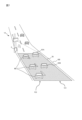
図1は、第1実施形態に係る交通情報提供システムの全体構成を示す図である。<Overall configuration of traffic information provision system>
FIG. 1 is a diagram showing the overall configuration of a traffic information providing system according to a first embodiment.
交通情報提供システム1は、道路100を走行する車両60の交通流を計測するシステムである。交通情報提供システム1は、センサ2と、情報生成装置としての交通流計測装置3とを備える。
The traffic
センサ2は、例えば、レーダセンサである。レーダセンサは、電波(送信波)を道路100上のエリア70に対して送信し、送信波の反射波を受信する。エリア70は、例えば、車両60の走行方向において数百メートルの長さを有する。
The
センサ2は、受信した反射波に基づいて、エリア70内の物体に対応する複数の測定点を得る。測定点は、例えば、反射波のレベルが、検知のための閾値よりも大きい箇所である。センサ2は、エリア70内の物体の複数の測定点からの反射波を受信し、受信した反射波に基づいて、センサ2から各測定点までの距離、センサ2を基準とした各測定点の方向(水平角)および各測定点の速度を測定する。複数の測定点は、車両検知のため、後述のようにクラスタリングされる。
The
一例として、センサ2は、送信アンテナと、複数の設置位置の異なる受信アンテナとを含んで構成される。センサ2は、周波数変調連続波(Frequency Modulated Continuous Wave;FM-CW)方式を用いて、反射波から各測定点の位置、方向および速度を測定する。センサ2は、測定点の位置、方向および速度を含む測定結果を、情報生成装置としての交通流計測装置3へ出力する。なお、電波は、例えば、24GHz帯、79GHz帯又は76GHz帯のミリ波である。送信波は、電波に代えて、20kHz以上の周波数を有する超音波であってもよい。
As an example, the
センサ2は、例えば、図1に示すように、センサ2よりも上流を走行する車両60を、車両60の正面から計測可能な位置に設置される。ただし、センサ2の設置位置は、これに限定されるものではない。例えば、センサ2は、センサ2よりも下流を走行する車両60を、車両60の後方から計測可能な位置に設置されてもよい。また、センサ2は、車両60の上方または側方から車両60を計測可能な位置に設置されてもよい。
For example, as shown in FIG. 1, the
交通流計測装置3は、センサ2から測定結果を受信し、道路100を走行する車両60の交通流を計測する。交通流は、例えば、単位時間当たりの台数、及び、平均速度の少なくともいずれか一つを含む。交通流は、車種ごとに計測される。すなわち、台数は、車種ごとに計測され、平均速度も車種ごとに計測される。交通流計測装置3は、計測した交通流を示す交通情報を、中央装置10に送信する。交通流計測装置3は、携帯電話網、専用の無線回線又は有線回線などの通信ネットワークを利用して、中央装置10に交通情報を送信する。中央装置10は、例えば、交通管制センターなどに設置されたサーバである。
The traffic
<交通流計測装置の構成> <Configuration of traffic flow measuring device>
図2は、第1実施形態に係る交通流計測装置3の構成を示すブロック図である。
FIG. 2 is a block diagram showing the configuration of the traffic
交通流計測装置3は、車両位置測定部31と、速度測定部32と、車両長測定部33と、精度検知部34と、車両追跡部35と、車両長決定部36と、車種決定部37と、交通流計測部38と、交通情報提供部39と、記憶部40とを備える。
The traffic
なお、交通流計測装置3は、CPU(Central Processing Unit)、ROM(Read Only Memory)、RAM(Random Access Memory)および通信I/F(インタフェース)などを備えるコンピュータにより構成することもできる。各処理部31~39は、CPU上でコンピュータプログラムを実行することにより機能的に実現される。
Note that the traffic
車両位置測定部31は、車両60の位置を測定する。より詳細には、車両位置測定部31は、センサ2から出力される各測定点の測定結果に基づいて、車両60の位置を測定する。
Vehicle
図3を参照して、車両60の位置の測定方法について説明する。図3は、センサ2から出力される各測定点の測定結果を示す図である。各測定点の測定結果は、距離、方向および速度からなる三次元空間中の点(図3中の黒点)として表される。
A method for measuring the position of
車両位置測定部31は、当該空間中の点(図3中の黒点)をクラスタリングする。例えば、車両位置測定部31は、速度がx(km/h)以内で、かつ方向がy(°)以内の点を1つのクラスタにクラスタリングする。ここでは、測定点がクラスタCAおよびCBの2つのクラスタに分類されている。1つのクラスタが1台の車両60を示す。このため、車両位置測定部31は、クラスタごとに距離が最小の点を、当該クラスタに対応する車両60の先端位置の点として特定する。車両位置測定部31は、先端位置の点に対応する距離および方向に基づいて、先端位置を計算することにより、車両60の先端位置を車両60の位置として測定する。当該位置は、例えば、2次元座標で示すことができる。
The vehicle
なお、車両位置測定部31は、センサ2がセンサ2よりも下流を走行する車両60を計測する場合には、車両60の後端位置を、車両60の位置として測定してもよい。また、車両位置測定部31は、センサ2が上方または側方から車両60を計測する場合には、車両60の先端位置および後端位置のうち事前に設定した位置を、車両60の位置として測定してもよい。
Note that, when the
車両位置測定部31は、測定した車両60の位置の情報を、当該位置の測定時刻の情報と対応付けて、車両60ごとに記憶部40に記憶させる。
The vehicle
速度測定部32は、センサ2から出力される各測定点の測定結果に基づいて、車両60の速度を測定する。
The
図3を参照して、車両60の速度の測定方法について説明する。上述したように、センサ2による測定点が車両60ごとにクラスタに分類されている。このため、速度測定部32は、各クラスタに含まれる測定点に対応する速度から、当該クラスタに対応する車両60の速度を測定する。例えば、速度測定部32は、クラスタに含まれる各測定点の速度の平均値または中央値を、当該クラスタに対応する車両60の速度として測定してもよい。速度測定部32は、測定した車両60の速度の情報を、記憶部40に記憶させる。
A method for measuring the speed of
車両長測定部(車両サイズ測定部)33は、車両60の車両長を測定する。より詳細には、車両長測定部33は、センサ2から出力される各測定点の測定結果に基づいて、車両60の車両長を測定する。例えば、車両長測定部33は、クラスタごとにクラスタに含まれる測定点の距離の最大値と最小値の差を、当該クラスタに対応する車両60の車両長として測定する。図3に示す例では、クラスタCAに対応する車両60の車両長がLAとして測定され、クラスタCBに対応する車両60の車両長がLBとして測定される。
The vehicle length measuring section (vehicle size measuring section) 33 measures the vehicle length of the
なお、クラスタCA,CBは、車幅も示すため、車両サイズ測定部33は、クラスタCA,CBに基づき、車幅を測定することもできる。また、センサ2の設置位置によっては、クラスタCA,CBは、車高を示すため、車両サイズ測定部33は、クラスタCA,CBに基づき、車高を測定することもできる。
Note that since the clusters CA and CB also indicate the vehicle width, the vehicle
車両長測定部33は、測定した車両60の車両長(測定車両長)等の測定車両サイズに関する情報を、記憶部40に記憶させる。ここで記憶される測定車両サイズ(測定車両長など)は、暫定値としての車両サイズである。
The vehicle
精度検知部34は、車両長測定部33が測定した車両長の測定結果(測定車両長)の測定精度を検知する。より詳細には、精度検知部34は、センサ2から出力される各測定点の測定結果に基づいて、車両60の車両長の測定結果の精度を判定する。
The
図3を参照して、車両長の測定結果の精度の検知方法について説明する。上述したように、センサ2による測定点が車両60ごとにクラスタに分類されている。各車両60のクラスタに含まれる測定点の数が多いほど、当該車両60の車両長の測定結果の精度は高くなる。したがって、精度検知部34は、各車両60のクラスタに含まれる測定点の数に基づいて、当該車両60の車両長の測定結果の精度を求める。精度検知部34は、各車両60のクラスタに含まれる測定点の数自体を、当該車両60の車両長の測定結果の精度としてもよいし、測定点の数から求められる指標を精度としてもよい。
With reference to FIG. 3, a method for detecting the accuracy of the vehicle length measurement result will be described. As described above, the measurement points by the
精度検知部34は、車両60の車両長の測定結果の精度の情報(測定精度;車両長精度)を、記憶部40に記憶させる。
The
つまり、記憶部40には、車両60ごとに、当該車両60の位置、当該位置の測定時刻、速度、車両長および車両長の測定結果の精度の情報が記憶される。
That is, the
交通流計測装置3は、エリア70内を走行することによって位置が変化する車両60を、エリア70内の複数の位置それぞれにおいて検知する。すなわち、車両位置測定部31は、同一車両の車両位置を、エリア70内の複数の位置それぞれにおいて測定する。また、速度測定部32は、同一車両の速度を、エリア70内の複数の位置それぞれにおいて測定し、車両長測定部33は、同一車両の速度を、エリア70内の複数の位置それぞれにおいて測定する。
The traffic
したがって、車両60の位置の測定時刻、速度、車両長および車両長の測定結果の精度の情報は、エリア70内の複数の位置それぞれにおいて測定又は検知され、複数の位置ごとに記憶部40に格納される。
Therefore, information on the measurement time, speed, vehicle length, and accuracy of the measurement result of the
車両追跡部35は、車両60を追跡する。車両追跡部35は、エリア70内の複数の位置で検知された走行車両60を、同一車両として判定するよう動作する。より詳細には、車両追跡部35は、記憶部40に記憶されている車両60ごとの情報に基づいて、測定時刻の異なる車両60の情報を対応付けることにより、車両60の追跡を行う。例えば、車両追跡部35は、カルマンフィルタを用いて、第1測定時刻における第1車両の位置および速度などの情報から、第2測定時刻における第1車両の位置を推定する。車両追跡部35は、第1車両の推定位置に最も近い第2測定時刻での測定位置を有する第2車両を、第1車両と同一車両であると判定することにより、第1車両の追跡を行う。
The
車両追跡部35は、同一車両と判断された第1車両および第2車両に同一の車両ID(識別子)を付与し、記憶部40に記憶させる。
The
車両長決定部36は、暫定値である測定車両長(測定車両サイズ)から、確定値としての決定車両サイズ(決定車両長)を求める。車両長決定部36は、車両追跡部35による車両の追跡結果および精度検知部34による車両長の測定結果の精度の判定結果に基づいて、同一の走行車両の車両長の測定結果の精度を比較する。車両長決定部36は、精度の比較結果に基づいて車両の車両長を決定する。実施形態においては、車両長決定部36は、同一車両の車両長のうち、最も精度が高いと判定された車両長を、当該車両の車両長(決定車両長)と決定する。
The vehicle
図4は、車両長決定部による車両長の決定方法について説明するための図である。図4を参照して、車両60は、道路100上のエリア70内を位置P1、P2、P3、P4、P5、P6の順に走行するものとする。車両長測定部33は、各位置P1、P2、P3、P4、P5、P6での車両60の車両長を測定する。精度検知部34は、測定された車両長(以下、「測定車両長」という)の測定結果それぞれの精度(以下、「車両長精度」という)を求める。例えば、位置P1における車両60の測定車両長および車両長精度の組は、(L1,30)となり、位置P2~P6における上記組は、それぞれ、(L2,42)、(L3,49)、(L4,56)、(L5,40)、(L6,30)となったとする。
FIG. 4 is a diagram for explaining a method for determining the vehicle length by the vehicle length determining section. Referring to FIG. 4, it is assumed that
つまり、位置P1から進むにつれ、車両60の車両長精度は大きくなり、位置P4において最高精度となるが、その後は、車両長精度が小さくなったとする。これは、センサ2から遠い位置では車両60の測定点の数が少なくなり、車両長精度が低くなる一方、車両60がセンサ2に近すぎる場合にもノイズの影響を受け、1つのクラスタに含まれる測定点の数が少なくなるからである。
In other words, assume that the vehicle length accuracy of the
車両長決定部36は、位置P1、P2、P3、P4、P5、P6の順に車両60の車両長を決定する。車両長決定部36は、各位置において、それまでに測定された車両60の測定車両長のうち、車両長精度が最高の測定車両長を、当該位置における車両60の車両長(決定車両長)として決定する。
The vehicle
例えば、車両長決定部36は、位置P1においては測定車両長L1しか測定しておらず測定車両長L1が最高精度であるため、測定車両長L1を決定車両長とする。また、車両長決定部36は、位置P2においては測定車両長L1およびL2の車両長精度のうち測定車両長L2の車両長精度「42」が最高精度であるため、測定車両長L2を決定車両長とする。同様に、車両長決定部36は、位置P3およびP4においては、それぞれ、測定車両長L3およびL4を決定車両長とする。
For example, the vehicle
さらに、車両長決定部36は、位置P5においては測定車両長L1~L5の車両長精度のうち測定車両長L4の車両長精度「56」が最高精度であるため、測定車両長L4を決定車両長とする。また、車両長決定部36は、位置P6においては測定車両長L1~L6の車両長精度のうち測定車両長L4の車両長精度「56」が最高精度であるため、測定車両長L4を決定車両長とする。
Further, the vehicle
このように、決定車両長は、車両長精度が増加し続ける位置P4までは順次更新されるが、位置P4を過ぎると、車両長精度が低下し続けるため更新されない。 In this way, the determined vehicle length is sequentially updated up to the position P4 where the vehicle length accuracy continues to increase, but is not updated after the position P4 because the vehicle length accuracy continues to decrease.
なお、車両長決定部36は、車両60がエリア70を通過した後に、位置P1~P6の車両長を決定するようにしてもよい。この場合、車両長決定部36は、測定車両長L1~L6の車両長精度のうち測定車両長L4の車両長精度「56」が最高精度であるため、位置P1~P6の決定車両長を、全てL4と決定してもよい。車両長決定部36は、決定車両長を、記憶部40に記憶させる。
Note that the vehicle
再び図2を参照して、車種決定部37は、車両長決定部36により決定された車両長に基づいて、車両60の車種を決定する。例えば、車種決定部37は、決定車両長が5.5m以上の場合には車両60の車種を大型車と決定し、決定車両長が5.5m未満の場合には車両60の車種を小型車と決定する。
Referring again to FIG. 2, vehicle
なお、同一の車両60について位置に応じて車両長が異なる場合がある。このような場合には、車種決定部37は、最高精度の車両長に基づいて車種を決定してもよい。つまり、図4に示した例では、車種決定部37は、車両長精度が最も高い位置P4の決定車両長L4に基づいて、車種を決定する。
Note that the vehicle length of the
また、車種決定部37は、車両長の代わりに車幅や車高が測定可能な場合には、車幅または車高を閾値処理することにより、車種を決定してもよい。車種決定部37は、決定した車種を、記憶部40に記憶させる。
Furthermore, if the vehicle width or vehicle height can be measured instead of the vehicle length, the vehicle
記憶部40は、HDD(Hard Disk Drive)やフラッシュメモリなどの記憶装置により構成され、上記した各種情報を記憶する。
The
図5は、記憶部40に記憶される情報の一例を示す図である。
記憶部40には、車両60の車両ID、位置、測定時刻、測定車両長、車両長精度、決定車両長および車種が組として記憶されている。例えば、車両ID「C1」の情報は、車両追跡部35により追跡された同一の車両の情報である。FIG. 5 is a diagram showing an example of information stored in the
The
交通流計測部38は、車両追跡部35による追跡結果に基づいて、車種ごとの車両60の交通流を計測する。一例として、交通流計測部38は、記憶部40に記憶されている情報を参照して、一定時間にエリア70を通過した大型車の台数と、小型車の台数とを、それぞれ交通流として計測する。なお、交通流計測部38は、車両追跡部35により同一の車両と判断され、同一の車両IDが付された情報を、同一の車両60の情報とみなして、車両60の台数を計測する。交通流は車両60の台数に限定されるものではなく、例えば、車両60の平均速度であってもよい。平均速度も車種ごとに計測できる。
The traffic
交通情報提供部39は、交通流計測部38が計測した車種ごとの車両60の交通流の情報を交通情報として中央装置10に送信することにより、交通情報を提供する。
The traffic
<交通流計測装置の処理手順>
図6は、本開示の実施の形態1に係る交通流計測装置の処理手順の一例を示すフローチャートである。<Processing procedure of traffic flow measuring device>
FIG. 6 is a flowchart illustrating an example of a processing procedure of the traffic flow measuring device according to
図6を参照して、車両位置測定部31は、センサ2から出力される各測定点の測定結果に基づいて、車両60の位置を測定して、測定結果を、車両60の車両IDとともに、記憶部40に記憶させる(S1)。なお、車両位置測定部31は、これまで車両IDとして付与していない値を、例えばランダムまたは連番で発生させて車両IDとして付与する。
Referring to FIG. 6, vehicle
速度測定部32は、センサ2から出力される各測定点の測定結果に基づいて、車両60の速度を測定し、測定結果を記憶部40に記憶させる(S2)。なお、測定結果は、ステップS1で生成された車両IDと対応付けられる。
The
車両長測定部33は、センサ2から出力される各測定点の測定結果に基づいて、車両60の車両長を測定し、測定車両長を、記憶部40に記憶させる(S3)。なお、測定車両長は、ステップS1で生成された車両IDと対応付けられる。
The vehicle
精度検知部34は、センサ2から出力される各測定点の測定結果に基づいて、車両60の車両長の測定結果の精度を判定し、判定した車両長精度を記憶部40に記憶させる(S4)。なお、車両長精度は、ステップS1で生成された車両IDと対応付けられる。
The
車両追跡部35は、記憶部40に記憶されている車両60ごとの情報に基づいて、測定時刻の異なる車両60の情報を対応付けることにより、車両60の追跡を行う(S5)。なお、車両追跡部35は、対応付けられた情報の車両IDが同一の値になるように、車両IDを更新する。
The
車両60を追跡することができた場合には(S5でYES)、車両長決定部36は、同一の車両IDの車両長の中で、ステップS3で測定された車両長が最高精度か否かを判定する(S6)。
If the
測定車両長が最高精度でなければ(S6でNO)、車両長決定部36は、測定した車両長を、最高精度の車両長に置換することにより、置換後の車両長を、車両60の車両長として決定する(S7)。
If the measured vehicle length is not the highest accuracy (NO in S6), the vehicle
その後、車両長決定部36は、決定車両長を記憶部40に記憶させる(S8)。なお、決定車両長は車両IDと対応付けられる。
After that, the vehicle
測定車両長が最高精度であれば(S6でYES)、車両長決定部36は、その測定車両長を、車両60の車両長と決定して、車両IDと対応付けて記憶部40に記憶させる(S8)。
If the measured vehicle length is the highest accuracy (YES in S6), the vehicle
車両60を追跡することができなかった場合には(S5でYES)、その車両60の測定車両長を、車両60の車両長と決定して、車両IDと対応付けて記憶部40に記憶させる。
If the
車種決定部37は、タイマの出力などに基づいて、ステップS1の処理を開始してから一定時間(例えば、1分)が経過したか否かを判断する(S9)。
The vehicle
一定時間が経過していなければ(S9でNO)、ステップS1以降の処理が繰り返し実行される。ステップS1以降の処理の繰り返しにより、車両位置、車両速度、車両長は、同一の走行車両について複数回測定される。車両長の測定精度は、複数の測定車両長それぞれについて検知される。 If the certain period of time has not elapsed (NO in S9), the processes from step S1 onwards are repeatedly executed. By repeating the process from step S1 onwards, the vehicle position, vehicle speed, and vehicle length are measured multiple times for the same traveling vehicle. The measurement accuracy of the vehicle length is detected for each of the plurality of measured vehicle lengths.
一定時間が経過していれば(S9でYES)、車種決定部37は、記憶部40に記憶されている情報に基づいて、情報ごとに、決定車両長から車種を決定し、決定した車種を車両IDと対応付けて記憶部40に記憶させる(S10)。ここまでの処理により、図5に示したような情報が記憶部40に記憶される。
If a certain period of time has elapsed (YES in S9), the vehicle
交通流計測部38は、記憶部40に記憶されている情報を参照して、一定時間にエリア70を通過した大型車の台数と、小型車の台数とを、それぞれ交通流として計測する(S11)。
The traffic
交通情報提供部39は、交通流計測部38が計測した車種ごとの車両60の交通流の情報を交通情報として中央装置10に送信することにより、交通情報を提供する(S12)。
The traffic
交通流計測装置3は、所定の終了条件を満たすか否かを判断する(S13)。例えば、交通流計測装置3は、外部より交通流計測装置3の処理の停止指示信号を受信した場合には、終了条件を満たすと判断してもよい。
The traffic
終了条件を満たす場合には(S13でYES)、交通流計測装置3は、処理を終了する。終了条件を満たさない場合には(S13でNO)、ステップS1以降の処理が繰り返し実行される。
If the termination condition is satisfied (YES in S13), the traffic
<第1実施形態の効果> <Effects of the first embodiment>
以上説明したように、第1実施形態によると、車両60を追跡し、同一の走行車両60について、ある時刻においてある位置で測定された車両長の測定結果の精度と、他の時刻において他の位置で測定された車両長の測定結果の精度とを比較し、比較結果に基づいて車両60の車両長を決定することができる。これにより、精度がより高い車両長を採用して、車両60の車両長と決定することができる。また、この構成によると、車両60が検知されるエリア70を広くして、エリア70内に車両サイズの測定精度が低くなる箇所が存在しても、測定精度が低い車両サイズの利用を回避できる。したがって、エリア70を広くすることができ、センサの設置数を抑えることができる。このため、低設置コストで、車両60の車両長を高精度に決定することができる。
As explained above, according to the first embodiment, the accuracy of the measurement result of the vehicle length measured at a certain position at a certain time for the same traveling
また、照射した電波に対する反射波の測定点が多い車両60ほど車両長の測定結果の精度が高いと判定することができる。これにより、車両長の測定結果の精度を正確に判定することができる。
Further, it can be determined that the
また、高精度な車両長に基づいて、車種を決定し、車種ごとの交通流を計測することができる。具体的には、所定時間ごとの車種別の車両60の台数を計測することができる。このため、車種ごとの交通流を高精度に計測することができる。
Furthermore, it is possible to determine the vehicle type based on highly accurate vehicle length and measure traffic flow for each vehicle type. Specifically, the number of
[第1実施形態の第1変形例] [First modification of the first embodiment]
上述の第1実施形態では、センサ2の一例としてレーダセンサを用いたが、センサ2はレーダセンサに限定されるものではない。センサ2としては、エリア70を略同時に観測可能なものであれば、他の装置を利用することができる。例えば、センサ2として、カメラを用いることもできるし、LiDAR(Light Detection and Ranging)を用いることもできる。
In the first embodiment described above, a radar sensor is used as an example of the
第1変形例では、センサ2としてカメラを用いる場合を説明する。この場合、交通流計測装置3の車両位置測定部31は、カメラがエリア70を撮影することにより得られる画像データを画像処理することにより、車両60の位置を特定する。例えば、車両位置測定部31は、背景差分法などを利用して車両60の位置を特定する。つまり、車両位置測定部31は、車両60が含まれていない時点でエリア70を撮影することにより得られた背景画像データと、カメラから出力される画像データとの差分データを二値化することにより二値化画像データを作成する。車両位置測定部31は、二値化画像データから車両60の像を抽出し、車両60ごとに位置を推定する。例えば、二値化画像データ中で、車両60の像ごとに最も上側の位置を特定し、当該位置に対応する三次元空間(実空間)中の位置を、車両60の位置と特定する。なお、画像データ中の位置と、三次元空間中の位置との関係は、事前のキャリブレーション等により既知であるものとする。
In the first modification, a case will be described in which a camera is used as the
車両長測定部33は、二値化画像データ中での車両60の像に基づいて、当該像の長さから、車両60の車両長を測定する。なお、画像データ中の各位置での像の長さと車両長との関係は、事前のキャリブレーション等により既知であるものとする。
The vehicle
精度検知部34は、二値化画像データ中での車両60の像に基づいて、車両長測定部33が測定した車両長の測定結果の精度を判定する。例えば、精度検知部34は、車両60の像に含まれる画素数が多いほど、車両長の測定結果の精度が高いと判定してもよい。つまり、精度検知部34は、画素数と精度との関係を示すテーブル情報に基づいて、画素数から精度を判定してもよい。
The
なお、センサ2としてカメラを用いる場合には、車両追跡部35は、例えば、カメラから出力される画像データからナンバープレートを認識し、フレーム間で同一ナンバーを有する車両60を対応付けることにより、車両60を追跡するようにしてもよい。
Note that when a camera is used as the
[第1実施形態の第2変形例] [Second modification of the first embodiment]
上述の第1実施形態の交通流計測装置3の精度検知部34は、クラスタに含まれる測定点の数に基づいて、車両長の測定結果の精度を検知したが、精度検知方法はこれに限定されるものではない。
Although the
例えば、事前に、実験用の車両60を用いて、車両60の位置ごとに、当該位置で車両長測定部33が測定した車両長と、正しい車両長との誤差を求め、誤差が小さい位置ほど車両長の測定結果の精度が高くなるような、車両60の位置と車両長の測定結果の精度との関係情報を求めておく。
For example, using the
運用時には、精度検知部34は、当該関係情報を参照し、車両位置測定部31が測定した車両60の位置に基づいて、当該位置に存在する車両60の車両長の測定結果の精度を検知する。
During operation, the
なお、実験用の車両60の位置と車両長の誤差とから上記関係情報を求める代わりに、例えば、実験用の車両60までの水平角または仰角と、水平角または仰角の測定値および真値の誤差とに基づいて、関係情報を求めてもよい。
Note that instead of obtaining the above relational information from the position of the
第2変形例によると、例えば、事前に車両長の測定誤差と車両の位置との関係を調査しておくことで、調査結果である関係情報に基づいて、車両60の位置から車両長の測定結果の精度を検知することができる。これにより、車両長の測定結果の精度を正確に検知することができる。
According to the second modification, for example, by investigating the relationship between the vehicle length measurement error and the vehicle position in advance, the vehicle length can be measured from the position of the
[第2実施形態] [Second embodiment]
<交通情報提供システムの全体構成> <Overall configuration of traffic information provision system>
図7は、第2実施形態に係る交通情報提供システムの全体構成を示す図である。 FIG. 7 is a diagram showing the overall configuration of a traffic information providing system according to the second embodiment.
交通情報提供システム1Aは、車両の運転を支援するシステムであり、センサ2と、情報生成装置としての運転支援装置5とを備える。実施形態の運転支援装置5は、ある車線101の外からその車線101内へ進入しようとする車両60に対する運転支援をする。
The traffic
以下では、車線101への進入として、道路100に含まれる第2車線102から、道路100に含まれる第1車線101への車線変更を例として想定して説明する。ただし、車線101への進入は、駐車場などの道路100外位置から、道路100に進入することであってもよい。
In the following description, a lane change from the
センサ2は、第1実施形態と同様のレーダセンサであり、例えば、図7に示すように、センサ2よりも上流のエリア70内を走行する車両60,60A,60Bを、車両60,60A,60Bの正面から計測可能な位置に設置される。センサ2により車両60,60A,60Bが検知されるエリア70は、道路100の第1車線101及び第2車線102を含む。なお、センサ2は、第1実施形態と同様、エリア70を走行する車両60,60A,60Bを、車両60,60A,60Bの後方から計測可能な位置に設置されてもよい。また、センサ2は、車両60,60A,60Bの上方または側方から車両60,60A,60Bを計測可能な位置に設置されてもよい。
The
以下では、第2車線102を走行する車両60が、第1走行車両60A及び第2走行車両60Bが走行する第1車線101へ車線変更する際における、車両60への運転支援について説明する。車両60への車線変更支援のため、第1車線を走行する車両60A,60Bに関する情報が、車両60へ提供される。ただし、以下で説明する運転支援は、第1車線101を走行する車両60A,60Bが、第2車線102へ車線変更する際にも同様に利用される。
Below, driving support for the
運転支援装置5は、センサ2から測定結果を受信し、第1車線101を走行する車両60A,60Bの位置および車両長に基づく第1情報を提供する。例えば、運転支援装置5は、第1車線101を走行する車両60A,60Bの位置および車両長の情報を車両情報(第1情報)として、第2車線102を走行する車両60に提供してもよい。また、運転支援装置5は、車両60A,60Bの位置および車両長に基づいて、車両60及び車両60Bの車間距離、および車両60A及び車両60Bの車間時間長などの情報を車両情報(第1情報)として作成し、この車両情報を車両60に提供してもよい。なお、第1車線101を走行する車両60A,60Bと、第2車線102を走行する車両60とは、センサ2によって測定された車両の位置(方向)によって区別される。
The driving
<運転支援装置の構成>
図8は、第2実施形態に係る運転支援装置5の構成を示すブロック図である。<Configuration of driving support device>
FIG. 8 is a block diagram showing the configuration of the driving
運転支援装置5は、車両位置測定部31と、速度測定部32と、車両長測定部33と、精度検知部34と、車両追跡部35と、車両長決定部36と、車両情報提供部51と、記憶部40とを備える。
The driving
なお、運転支援装置5は、CPU、ROM、RAMおよび通信I/Fなどを備えるコンピュータにより構成することもできる。各処理部31~36および51は、CPU上でコンピュータプログラムを実行することにより機能的に実現される。
Note that the driving
各処理部31~36は、第1実施形態に示したものと同様である。このため、その詳細な説明はここでは繰り返さない。
Each of the
車両情報提供部51は、車両位置測定部31が測定した車両60A,60Bの位置と、車両長決定部36が決定した車両60A,60Bの車両長とに基づいて、車両情報(第1情報)を生成する。車両情報(第1情報)は、第2車線102を走行する車両60に対して第1車線101への車線変更を支援するための情報である。車両情報提供部51は、生成した車両情報(第1情報)を無線により車両60に送信する。なお、車両情報は、車両60A、60Bによって受信されてもよい。
The vehicle
実施形態に係る車両情報(第1情報)は、少なくとも決定車両サイズ(決定車両長)に基づく情報を含むのが好ましい。決定車両サイズ(決定車両長)に基づく情報は、決定車両サイズ(決定車両長)自体であってもよいし、決定車両サイズ(決定車両長)から求められた情報であってもよい。車両情報(第1情報)は、車両の位置に基づく情報を含むのが好ましい。車両の位置に基づく情報は、車両の位置自体であってもよいし、車両の位置から求められた情報であってもよい。例えば、車両情報提供部51は、第1車線101を走行する車両60A,60Bの位置および車両長(決定車両長)の情報を車両情報(第1情報)として生成してもよい。
The vehicle information (first information) according to the embodiment preferably includes at least information based on the determined vehicle size (determined vehicle length). The information based on the determined vehicle size (determined vehicle length) may be the determined vehicle size (determined vehicle length) itself, or may be information obtained from the determined vehicle size (determined vehicle length). The vehicle information (first information) preferably includes information based on the location of the vehicle. The information based on the location of the vehicle may be the location of the vehicle itself, or may be information obtained from the location of the vehicle. For example, the vehicle
また、車両情報提供部51は、車両61の車間距離および車間時間の情報を含む車間データを車両情報(第1情報)として生成してもよい。具体的には、車両情報提供部51は、車両60A,60Bの位置および各車両60A,60Bの車両長に基づいて、車両60A,60Bごとに先端位置P1,P2および後端位置P11,P12を特定する(図10参照)。例えば、車両情報提供部51は、車両位置測定部31が測定した車両60Aの先端位置P1に車両長(決定車両長)を足し合わせることにより、車両61の後端位置P12を特定する。車両情報提供部51は、第1車線101を走行する前後方向に隣接する車両60A,60Bの組ごとに、前方車両60Aの後端位置P11から後方車両60Bの先端位置P2までの距離である車間距離(車間データ)を算出する。なお、車両情報提供部51は、車間距離を後方車両60Bが走行するために必要な時間を、車間距離と後方車両60Bの速度から車間時間長(車間データ)として算出してもよい。
Further, the vehicle
車間データは、車両60A,60B以外の車両60が、車両60Aと車両60Bとの間を走行しようとする場合に有用である。車両60が車両60Aと車両60Bとの間を走行することは、例えば、車両60が車線変更することによって生じる。また、車両60が車両60Aと車両60Bとの間を走行しようとすることは、車両60が交差点において、対向車線を横切って曲がる場合にも生じる。例えば、日本のように、車両が左車線を走行する国においては、交差点において対向車線を横切ることは右折時に生じる。このような場合において、車間データは、有用である。
The inter-vehicle distance data is useful when a
車両情報提供部51は、作成した車両情報(第1情報)を車両60に送信する。これにより、第2車線102を走行する車両60は、第1車線101への車線変更位置又は車線変更タイミングを決定することができ、スムーズに車線変更することができる。
The vehicle
なお、車両情報提供部51は、車両情報を送信する際に、車両60A,60Bの位置等の測定時刻の情報(第2情報)と車両情報(第1情報)とを対応付けて送信してもよい。運転支援装置5と車両60との間の通信状況によっては、車両情報提供部51が提供した車両情報を車両60が受信するまでの間に時間遅れが生じる場合がある。しかし、この構成によると、車両60A,60Bの位置等の測定時刻の情報を車両60に提供することができる。このため、車両60側では、測定時刻と現在時刻とに基づいて、車両60A,60Bの位置を補正することができる。これにより、第2車線102を走行する車両60は、正確に、第1車線101への車線変更位置や車線変更タイミングなどを決定することができる。
In addition, when transmitting the vehicle information, the vehicle
なお、車両60に提供される車両情報(第1情報)が、車両60A,60Bの位置および各車両60A,60Bの決定車両長を含むが、車間データを含まない場合、車両情報を受信した車両60が、車両60A,60Bの位置および各車両60A,60Bの決定車両長から、車間データを生成してもよい。
Note that if the vehicle information (first information) provided to the
記憶部40には、図5に示したのと同様の情報が記憶される。ただし、車種の情報は記憶されない。
The
<運転支援装置の処理手順>
図9は、第2実施形態に係る運転支援装置5の処理手順の一例を示すフローチャートである。<Processing procedure of driving support device>
FIG. 9 is a flowchart showing an example of the processing procedure of the driving
図9を参照して、運転支援装置5は、ステップS1~S8の処理を実行する。これらの処理は、図6を用いて説明したものと同様である。このため、その詳細な説明はここでは繰り返さない。
Referring to FIG. 9, driving
車両情報提供部51は、車両位置測定部31が測定した車両61の位置と、車両長決定部36が決定した車両61の決定車両長とに基づいて、第2車線102を走行する車両60に対して第1車線101への車線変更を支援するための車両情報を作成する(S21)。
The vehicle
車両情報提供部51は、作成した車両情報を、無線により車両60に送信することにより、車両情報を提供する(S22)。
The vehicle
運転支援装置5は、第1実施形態で説明したのと同様の終了条件を満たすか否かを判断する(S13)。
The driving
終了条件を満たす場合には(S13でYES)、運転支援装置5は、処理を終了する。終了条件を満たさない場合には(S13でNO)、ステップS1以降の処理が繰り返し実行される。
If the termination condition is satisfied (YES in S13), the driving
<第2実施形態の効果> <Effects of the second embodiment>
以上説明したように、第2実施形態によると、第2車線102を走行する車両60に対して、第1車線101を走行する車両60A,60Bの位置および車両長などの車両情報を提供することができる。これにより、第2車線102を走行する車両60は、第1車線101への車線変更位置や車線変更タイミングなどを決定することができ、これにより、車両60の車線変更を支援することができる。
As explained above, according to the second embodiment, vehicle information such as the positions and vehicle lengths of the
[付記] [Additional notes]
コンピュータを、交通流計測装置3または運転支援装置5として機能させるためのコンピュータプログラムは、コンピュータ読取可能な非一時的な記録媒体、例えば、HDD、CD-ROM、半導体メモリなどに記録したものとしてもよい。
The computer program for making the computer function as the traffic
また、上記コンピュータプログラムを、電気通信回線、無線または有線通信回線、インターネットを代表とするネットワーク、データ放送等を経由して伝送するものとしてもよい。
また、上記各装置は、複数のコンピュータにより実現されてもよい。Further, the computer program may be transmitted via a telecommunication line, a wireless or wired communication line, a network typified by the Internet, data broadcasting, or the like.
Further, each of the above devices may be realized by a plurality of computers.
また、上記各装置の一部または全部の機能がクラウドコンピューティングによって提供されてもよい。つまり、各装置の一部または全部の機能がクラウドサーバにより実現されていてもよい。例えば、交通流計測装置3の交通流計測部38の機能がクラウドサーバにより実現され、交通流計測装置3は、クラウドサーバに対して、記憶部40に記憶されている情報を送信し、クラウドサーバから交通流の情報を受信する構成であってもよい。
Further, some or all of the functions of each of the above devices may be provided by cloud computing. In other words, some or all of the functions of each device may be realized by a cloud server. For example, the function of the traffic
さらに、上記実施の形態および上記変形例の少なくとも一部を任意に組み合わせるとしてもよい。 Furthermore, at least some of the embodiments and modifications described above may be combined arbitrarily.
今回開示された実施の形態はすべての点で例示であって制限的なものではないと考えられるべきである。本発明の範囲は、上記した意味ではなく、請求の範囲によって示され、請求の範囲と均等の意味および範囲内でのすべての変更が含まれることが意図される。 The embodiments disclosed this time should be considered to be illustrative in all respects and not restrictive. The scope of the present invention is indicated by the scope of the claims, not the meaning described above, and is intended to include meanings equivalent to the scope of the claims and all changes within the scope.
1 交通情報提供システム
1A 交通情報提供システム
2 センサ
3 交通流計測装置
5 運転支援装置
10 中央装置
31 車両位置測定部
32 速度測定部
33 車両長測定部(車両サイズ測定部)
34 精度検知部
35 車両追跡部
36 車両長決定部
37 車種決定部
38 交通流計測部
39 交通情報提供部
40 記憶部
51 車両情報提供部
60 車両
60A 車両
60B 車両
70 エリア
100 道路
101 第1車線
102 第2車線
P1 先端位置
P11 後端位置
P12 後端位置
P2 先端位置
1 Traffic
34
Claims (16)
同一の走行車両について車両サイズの測定を複数回行うことで、前記測定点のクラスタに基づく複数の測定結果を得るための車両サイズ測定部と、
前記複数の測定結果それぞれの精度を検知するための検知部と、
前記精度に基づいて、前記複数の測定結果から、前記走行車両の車両サイズを決定するための決定部と、
を備え、
前記精度は、前記クラスタに含まれる前記測定点の数に基づいて検知される
情報生成装置。 For clustering measurement points obtained from reflected waves of transmitted waves irradiated onto a road by a radar sensor in a three-dimensional space of distance from the radar sensor, direction with respect to the radar sensor, and speed of the measurement point. a position measurement unit;
a vehicle size measurement unit for obtaining a plurality of measurement results based on clusters of the measurement points by measuring the vehicle size of the same traveling vehicle multiple times;
a detection unit for detecting the accuracy of each of the plurality of measurement results;
a determining unit for determining the vehicle size of the traveling vehicle from the plurality of measurement results based on the accuracy;
Equipped with
The accuracy is detected based on the number of the measurement points included in the cluster. Information generation device.
請求項1に記載の情報生成装置。 The information generation device according to claim 1, wherein the determining unit is configured to determine the measurement result with the highest accuracy among the plurality of measurement results as the vehicle size.
請求項1又は請求項2に記載の情報生成装置。 The information generation device according to claim 1 or 2, wherein the plurality of measurement results are measurement results measured at each of a plurality of positions.
請求項3に記載の情報生成装置。 The information generation device according to claim 3, further comprising a tracking unit for determining vehicles detected at the plurality of positions as the same traveling vehicle.
請求項1から請求項4のいずれか1項に記載の情報生成装置。 The information generation device according to any one of claims 1 to 4, further comprising a vehicle type determining section for determining the vehicle type of the traveling vehicle based on the vehicle size determined by the determining section.
請求項5に記載の情報生成装置。 The information generation device according to claim 5, further comprising a measurement unit configured to measure traffic flow for each vehicle type based on the vehicle type determined by the vehicle type determination unit.
請求項6に記載の情報生成装置。 The information generation device according to claim 6, wherein the traffic flow for each vehicle type includes the number of vehicles for each vehicle type.
請求項1から請求項7のいずれか1項に記載の情報生成装置。 The information generation device according to any one of claims 1 to 7, further comprising a providing unit for providing first information based on the vehicle size determined by the vehicle size determining unit.
請求項8に記載の情報生成装置。 The information generation device according to claim 8, wherein the first information is further based on the position of the traveling vehicle.
請求項9に記載の情報生成装置。 The information generating device according to claim 9, wherein the providing unit is configured to further provide second information indicating a measurement time of the position.
前記決定車両サイズは、少なくとも車両長を示し、
前記車間データは、少なくとも前記第1走行車両の前記車両サイズが示す車両長を用いて求められる
請求項8から請求項10のいずれか1項に記載の情報生成装置。 The first information includes inter-vehicle data between a first running vehicle and a second running vehicle running behind the first running vehicle,
The determined vehicle size indicates at least a vehicle length,
The information generation device according to any one of claims 8 to 10, wherein the inter-vehicle distance data is obtained using at least a vehicle length indicated by the vehicle size of the first traveling vehicle.
請求項11に記載の情報生成装置。 The information generation device according to claim 11, wherein the inter-vehicle data includes at least one of an inter-vehicle distance and an inter-vehicle time length.
請求項11又は請求項12に記載の情報生成装置。 The information generating device according to claim 11 or 12, wherein the first information is provided to a vehicle that is about to enter a lane in which the first traveling vehicle and the second traveling vehicle are traveling.
前記車両サイズが示す前記車両長及び前記走行車両の位置に基づく第1情報を提供するための提供部をさらに備え、
前記第1情報は、他の車両への提供用である
請求項1に記載の情報生成装置。 The vehicle size indicates at least a vehicle length,
Further comprising a providing unit for providing first information based on the vehicle length indicated by the vehicle size and the position of the traveling vehicle,
The information generating device according to claim 1, wherein the first information is for providing to another vehicle.
同一の走行車両について車両サイズの測定を複数回行うことで、前記測定点のクラスタに基づく複数の測定結果を得ること、
前記複数の測定結果それぞれの精度を検知すること、及び
前記精度に基づいて、前記複数の測定結果から、前記走行車両の車両サイズを決定すること、
を備え、
前記精度は、前記クラスタに含まれる前記測定点の数に基づいて検知される
情報生成方法。 Clustering measurement points obtained from reflected waves of transmitted waves irradiated onto a road by a radar sensor in a three-dimensional space of distance from the radar sensor, direction with respect to the radar sensor, and speed of the measurement point;
Obtaining a plurality of measurement results based on clusters of the measurement points by measuring the vehicle size for the same traveling vehicle multiple times;
detecting the accuracy of each of the plurality of measurement results; and determining the vehicle size of the traveling vehicle from the plurality of measurement results based on the accuracy;
Equipped with
The accuracy is detected based on the number of the measurement points included in the cluster.
前記情報生成装置は、
レーダセンサによって道路に照射された送信波の反射波から得られる測定点を、レーダセンサからの距離、前記レーダセンサを基準とした方向、及び前記測定点の速度の三次元空間においてクラスタリングするための位置測定部と、
同一の走行車両について車両サイズの測定を複数回行うことで、前記測定点のクラスタに基づく複数の測定結果を得るための車両サイズ測定部と、
前記複数の測定結果それぞれの精度を検知するための検知部と、
前記精度に基づいて、前記複数の測定車両サイズから、前記走行車両の車両サイズを決定するための決定部と、
を備え、
前記精度は、前記クラスタに含まれる前記測定点の数に基づいて検知される
コンピュータプログラム。
A computer program for operating a computer as an information generating device,
The information generation device includes:
For clustering measurement points obtained from reflected waves of transmitted waves irradiated onto a road by a radar sensor in a three-dimensional space of distance from the radar sensor, direction with respect to the radar sensor, and speed of the measurement point. a position measurement unit;
a vehicle size measuring unit for obtaining a plurality of measurement results based on clusters of the measurement points by measuring the vehicle size of the same traveling vehicle multiple times;
a detection unit for detecting the accuracy of each of the plurality of measurement results;
a determining unit for determining the vehicle size of the traveling vehicle from the plurality of measured vehicle sizes based on the accuracy;
Equipped with
The accuracy is detected based on the number of the measurement points included in the cluster. The computer program.
Applications Claiming Priority (1)
| Application Number | Priority Date | Filing Date | Title |
|---|---|---|---|
| PCT/JP2019/044975 WO2021095269A1 (en) | 2019-11-15 | 2019-11-15 | Information generation device, information generation method, and computer program |
Publications (3)
| Publication Number | Publication Date |
|---|---|
| JPWO2021095269A1 JPWO2021095269A1 (en) | 2021-05-20 |
| JPWO2021095269A5 JPWO2021095269A5 (en) | 2022-07-14 |
| JP7380705B2 true JP7380705B2 (en) | 2023-11-15 |
Family
ID=75912000
Family Applications (1)
| Application Number | Title | Priority Date | Filing Date |
|---|---|---|---|
| JP2021555777A Active JP7380705B2 (en) | 2019-11-15 | 2019-11-15 | Information generation device, information generation method, and computer program |
Country Status (4)
| Country | Link |
|---|---|
| US (1) | US20220398850A1 (en) |
| JP (1) | JP7380705B2 (en) |
| CN (1) | CN114631038A (en) |
| WO (1) | WO2021095269A1 (en) |
Citations (9)
| Publication number | Priority date | Publication date | Assignee | Title |
|---|---|---|---|---|
| US5528234A (en) | 1994-02-01 | 1996-06-18 | Mani; Siva A. | Traffic monitoring system for determining vehicle dimensions, speed, and class |
| JP2002056493A (en) | 2000-08-07 | 2002-02-22 | Hitachi Ltd | Vehicle specifying device |
| JP2004005726A (en) | 2003-07-24 | 2004-01-08 | Fujitsu Ltd | Traffic flow monitoring system for moving-body |
| JP2017096792A (en) | 2015-11-25 | 2017-06-01 | 株式会社デンソーウェーブ | Traffic density measuring device |
| WO2018085107A1 (en) | 2016-11-02 | 2018-05-11 | Peloton Technology, Inc. | Gap measurement for vehicle convoying |
| JP2019070566A (en) | 2017-10-06 | 2019-05-09 | 日本無線株式会社 | Radar signal processor and radar signal processing program |
| JP2019070567A (en) | 2017-10-06 | 2019-05-09 | 日本無線株式会社 | Moving object recognizing radar device |
| JP2019185220A (en) | 2018-04-04 | 2019-10-24 | パナソニック株式会社 | Traffic monitoring system and method for monitoring traffic |
| JP2020126008A (en) | 2019-02-05 | 2020-08-20 | 古河電気工業株式会社 | Radar device and control method of radar device |
-
2019
- 2019-11-15 WO PCT/JP2019/044975 patent/WO2021095269A1/en active Application Filing
- 2019-11-15 JP JP2021555777A patent/JP7380705B2/en active Active
- 2019-11-15 CN CN201980101626.2A patent/CN114631038A/en active Pending
- 2019-11-15 US US17/770,229 patent/US20220398850A1/en active Pending
Patent Citations (9)
| Publication number | Priority date | Publication date | Assignee | Title |
|---|---|---|---|---|
| US5528234A (en) | 1994-02-01 | 1996-06-18 | Mani; Siva A. | Traffic monitoring system for determining vehicle dimensions, speed, and class |
| JP2002056493A (en) | 2000-08-07 | 2002-02-22 | Hitachi Ltd | Vehicle specifying device |
| JP2004005726A (en) | 2003-07-24 | 2004-01-08 | Fujitsu Ltd | Traffic flow monitoring system for moving-body |
| JP2017096792A (en) | 2015-11-25 | 2017-06-01 | 株式会社デンソーウェーブ | Traffic density measuring device |
| WO2018085107A1 (en) | 2016-11-02 | 2018-05-11 | Peloton Technology, Inc. | Gap measurement for vehicle convoying |
| JP2019070566A (en) | 2017-10-06 | 2019-05-09 | 日本無線株式会社 | Radar signal processor and radar signal processing program |
| JP2019070567A (en) | 2017-10-06 | 2019-05-09 | 日本無線株式会社 | Moving object recognizing radar device |
| JP2019185220A (en) | 2018-04-04 | 2019-10-24 | パナソニック株式会社 | Traffic monitoring system and method for monitoring traffic |
| JP2020126008A (en) | 2019-02-05 | 2020-08-20 | 古河電気工業株式会社 | Radar device and control method of radar device |
Also Published As
| Publication number | Publication date |
|---|---|
| JPWO2021095269A1 (en) | 2021-05-20 |
| CN114631038A (en) | 2022-06-14 |
| WO2021095269A1 (en) | 2021-05-20 |
| US20220398850A1 (en) | 2022-12-15 |
Similar Documents
| Publication | Publication Date | Title |
|---|---|---|
| JP7152395B2 (en) | Gap measurement for vehicle platoons | |
| US20200180636A1 (en) | Apparatus and method for controlling running of vehicle | |
| US11002849B2 (en) | Driving lane detection device and driving lane detection method | |
| US10132919B2 (en) | Object detecting device, radar device, and object detection method | |
| EP3339896B1 (en) | Object detection device and recording medium | |
| CN111284493A (en) | Apparatus and method for controlling vehicle travel | |
| JP6717240B2 (en) | Target detection device | |
| US11351997B2 (en) | Collision prediction apparatus and collision prediction method | |
| US10074277B2 (en) | Method for ascertaining a parking area of a street section | |
| CN110879399B (en) | Method, device, vehicle, electronic device and medium for processing point cloud data | |
| JP5949467B2 (en) | Monitoring device | |
| JP4003586B2 (en) | Inter-vehicle distance measuring device | |
| JP5888275B2 (en) | Road edge detection system, method and program | |
| JP7380705B2 (en) | Information generation device, information generation method, and computer program | |
| JP7344744B2 (en) | Roadside edge detection method and roadside edge detection device | |
| JP4670449B2 (en) | Object detection device | |
| JP2018036075A (en) | Own vehicle position specification device and own vehicle position specification method | |
| JP2020020690A (en) | Vehicle position estimating device | |
| JP7414603B2 (en) | Track boundary determination device and track boundary determination method | |
| JP2019215177A (en) | Track setting device | |
| WO2022102371A1 (en) | Object detection device and object detection method | |
| JP4304260B2 (en) | Vehicle distance measurement method | |
| CN117492003A (en) | Control method of vehicle-mounted radar, radar and storage medium | |
| JP2021170029A (en) | Measurement device, measurement method, and program | |
| JP2022079198A (en) | Object detection device and object detection method |
Legal Events
| Date | Code | Title | Description |
|---|---|---|---|
| A521 | Request for written amendment filed |
Free format text: JAPANESE INTERMEDIATE CODE: A523 Effective date: 20220217 |
|
| A621 | Written request for application examination |
Free format text: JAPANESE INTERMEDIATE CODE: A621 Effective date: 20220621 |
|
| A131 | Notification of reasons for refusal |
Free format text: JAPANESE INTERMEDIATE CODE: A131 Effective date: 20230509 |
|
| A521 | Request for written amendment filed |
Free format text: JAPANESE INTERMEDIATE CODE: A523 Effective date: 20230707 |
|
| TRDD | Decision of grant or rejection written | ||
| A01 | Written decision to grant a patent or to grant a registration (utility model) |
Free format text: JAPANESE INTERMEDIATE CODE: A01 Effective date: 20231003 |
|
| A61 | First payment of annual fees (during grant procedure) |
Free format text: JAPANESE INTERMEDIATE CODE: A61 Effective date: 20231016 |
|
| R150 | Certificate of patent or registration of utility model |
Ref document number: 7380705 Country of ref document: JP Free format text: JAPANESE INTERMEDIATE CODE: R150 |