JP7376552B2 - System for automatic exposure and lighting control to maintain a predetermined target brightness of the displayed scene - Google Patents
System for automatic exposure and lighting control to maintain a predetermined target brightness of the displayed scene Download PDFInfo
- Publication number
- JP7376552B2 JP7376552B2 JP2021179417A JP2021179417A JP7376552B2 JP 7376552 B2 JP7376552 B2 JP 7376552B2 JP 2021179417 A JP2021179417 A JP 2021179417A JP 2021179417 A JP2021179417 A JP 2021179417A JP 7376552 B2 JP7376552 B2 JP 7376552B2
- Authority
- JP
- Japan
- Prior art keywords
- scene
- brightness
- camera
- power output
- optical power
- Prior art date
- Legal status (The legal status is an assumption and is not a legal conclusion. Google has not performed a legal analysis and makes no representation as to the accuracy of the status listed.)
- Active
Links
- 230000003287 optical effect Effects 0.000 claims description 227
- 238000000034 method Methods 0.000 claims description 166
- 238000005286 illumination Methods 0.000 claims description 95
- 230000008859 change Effects 0.000 claims description 61
- 238000001514 detection method Methods 0.000 claims description 33
- 230000004044 response Effects 0.000 claims description 12
- 238000004590 computer program Methods 0.000 claims description 5
- 230000002238 attenuated effect Effects 0.000 claims description 4
- 230000008569 process Effects 0.000 description 147
- 229920006395 saturated elastomer Polymers 0.000 description 72
- 230000007423 decrease Effects 0.000 description 25
- 230000009467 reduction Effects 0.000 description 21
- 238000012545 processing Methods 0.000 description 20
- 238000010586 diagram Methods 0.000 description 15
- 230000002829 reductive effect Effects 0.000 description 15
- 230000007704 transition Effects 0.000 description 10
- 230000001360 synchronised effect Effects 0.000 description 8
- 230000000451 tissue damage Effects 0.000 description 8
- 231100000827 tissue damage Toxicity 0.000 description 8
- 238000011946 reduction process Methods 0.000 description 7
- 238000013459 approach Methods 0.000 description 6
- 238000004364 calculation method Methods 0.000 description 5
- 230000006870 function Effects 0.000 description 5
- 238000012544 monitoring process Methods 0.000 description 5
- 230000000670 limiting effect Effects 0.000 description 4
- 230000026676 system process Effects 0.000 description 4
- 230000004888 barrier function Effects 0.000 description 3
- 238000003384 imaging method Methods 0.000 description 3
- 238000011017 operating method Methods 0.000 description 3
- 230000008901 benefit Effects 0.000 description 2
- 238000012886 linear function Methods 0.000 description 2
- 238000005259 measurement Methods 0.000 description 2
- 238000005096 rolling process Methods 0.000 description 2
- 238000003860 storage Methods 0.000 description 2
- 238000001356 surgical procedure Methods 0.000 description 2
- 230000036962 time dependent Effects 0.000 description 2
- 229910052724 xenon Inorganic materials 0.000 description 2
- FHNFHKCVQCLJFQ-UHFFFAOYSA-N xenon atom Chemical compound [Xe] FHNFHKCVQCLJFQ-UHFFFAOYSA-N 0.000 description 2
- 238000012084 abdominal surgery Methods 0.000 description 1
- 230000003213 activating effect Effects 0.000 description 1
- 210000003484 anatomy Anatomy 0.000 description 1
- 230000000740 bleeding effect Effects 0.000 description 1
- 210000004204 blood vessel Anatomy 0.000 description 1
- 238000005282 brightening Methods 0.000 description 1
- 239000011248 coating agent Substances 0.000 description 1
- 238000000576 coating method Methods 0.000 description 1
- 230000008878 coupling Effects 0.000 description 1
- 238000010168 coupling process Methods 0.000 description 1
- 238000005859 coupling reaction Methods 0.000 description 1
- 230000003247 decreasing effect Effects 0.000 description 1
- 230000001934 delay Effects 0.000 description 1
- 230000003111 delayed effect Effects 0.000 description 1
- 230000000694 effects Effects 0.000 description 1
- 239000000835 fiber Substances 0.000 description 1
- 208000014674 injury Diseases 0.000 description 1
- 230000003993 interaction Effects 0.000 description 1
- 238000002372 labelling Methods 0.000 description 1
- QSHDDOUJBYECFT-UHFFFAOYSA-N mercury Chemical compound [Hg] QSHDDOUJBYECFT-UHFFFAOYSA-N 0.000 description 1
- 229910052753 mercury Inorganic materials 0.000 description 1
- 239000013307 optical fiber Substances 0.000 description 1
- 238000011084 recovery Methods 0.000 description 1
- 230000002441 reversible effect Effects 0.000 description 1
- 238000007619 statistical method Methods 0.000 description 1
- 230000008733 trauma Effects 0.000 description 1
- 230000000007 visual effect Effects 0.000 description 1
- 238000012800 visualization Methods 0.000 description 1
Images


Classifications
-
- A—HUMAN NECESSITIES
- A61—MEDICAL OR VETERINARY SCIENCE; HYGIENE
- A61B—DIAGNOSIS; SURGERY; IDENTIFICATION
- A61B34/00—Computer-aided surgery; Manipulators or robots specially adapted for use in surgery
- A61B34/30—Surgical robots
-
- A—HUMAN NECESSITIES
- A61—MEDICAL OR VETERINARY SCIENCE; HYGIENE
- A61B—DIAGNOSIS; SURGERY; IDENTIFICATION
- A61B1/00—Instruments for performing medical examinations of the interior of cavities or tubes of the body by visual or photographical inspection, e.g. endoscopes; Illuminating arrangements therefor
- A61B1/00002—Operational features of endoscopes
- A61B1/00004—Operational features of endoscopes characterised by electronic signal processing
- A61B1/00006—Operational features of endoscopes characterised by electronic signal processing of control signals
-
- A—HUMAN NECESSITIES
- A61—MEDICAL OR VETERINARY SCIENCE; HYGIENE
- A61B—DIAGNOSIS; SURGERY; IDENTIFICATION
- A61B1/00—Instruments for performing medical examinations of the interior of cavities or tubes of the body by visual or photographical inspection, e.g. endoscopes; Illuminating arrangements therefor
- A61B1/00002—Operational features of endoscopes
- A61B1/00004—Operational features of endoscopes characterised by electronic signal processing
- A61B1/00009—Operational features of endoscopes characterised by electronic signal processing of image signals during a use of endoscope
-
- A—HUMAN NECESSITIES
- A61—MEDICAL OR VETERINARY SCIENCE; HYGIENE
- A61B—DIAGNOSIS; SURGERY; IDENTIFICATION
- A61B1/00—Instruments for performing medical examinations of the interior of cavities or tubes of the body by visual or photographical inspection, e.g. endoscopes; Illuminating arrangements therefor
- A61B1/00002—Operational features of endoscopes
- A61B1/00043—Operational features of endoscopes provided with output arrangements
- A61B1/00055—Operational features of endoscopes provided with output arrangements for alerting the user
-
- A—HUMAN NECESSITIES
- A61—MEDICAL OR VETERINARY SCIENCE; HYGIENE
- A61B—DIAGNOSIS; SURGERY; IDENTIFICATION
- A61B1/00—Instruments for performing medical examinations of the interior of cavities or tubes of the body by visual or photographical inspection, e.g. endoscopes; Illuminating arrangements therefor
- A61B1/00002—Operational features of endoscopes
- A61B1/00062—Operational features of endoscopes provided with means for preventing overuse
-
- A—HUMAN NECESSITIES
- A61—MEDICAL OR VETERINARY SCIENCE; HYGIENE
- A61B—DIAGNOSIS; SURGERY; IDENTIFICATION
- A61B1/00—Instruments for performing medical examinations of the interior of cavities or tubes of the body by visual or photographical inspection, e.g. endoscopes; Illuminating arrangements therefor
- A61B1/00163—Optical arrangements
- A61B1/00165—Optical arrangements with light-conductive means, e.g. fibre optics
-
- A—HUMAN NECESSITIES
- A61—MEDICAL OR VETERINARY SCIENCE; HYGIENE
- A61B—DIAGNOSIS; SURGERY; IDENTIFICATION
- A61B1/00—Instruments for performing medical examinations of the interior of cavities or tubes of the body by visual or photographical inspection, e.g. endoscopes; Illuminating arrangements therefor
- A61B1/00163—Optical arrangements
- A61B1/00193—Optical arrangements adapted for stereoscopic vision
-
- A—HUMAN NECESSITIES
- A61—MEDICAL OR VETERINARY SCIENCE; HYGIENE
- A61B—DIAGNOSIS; SURGERY; IDENTIFICATION
- A61B1/00—Instruments for performing medical examinations of the interior of cavities or tubes of the body by visual or photographical inspection, e.g. endoscopes; Illuminating arrangements therefor
- A61B1/04—Instruments for performing medical examinations of the interior of cavities or tubes of the body by visual or photographical inspection, e.g. endoscopes; Illuminating arrangements therefor combined with photographic or television appliances
- A61B1/045—Control thereof
-
- A—HUMAN NECESSITIES
- A61—MEDICAL OR VETERINARY SCIENCE; HYGIENE
- A61B—DIAGNOSIS; SURGERY; IDENTIFICATION
- A61B1/00—Instruments for performing medical examinations of the interior of cavities or tubes of the body by visual or photographical inspection, e.g. endoscopes; Illuminating arrangements therefor
- A61B1/06—Instruments for performing medical examinations of the interior of cavities or tubes of the body by visual or photographical inspection, e.g. endoscopes; Illuminating arrangements therefor with illuminating arrangements
- A61B1/0655—Control therefor
-
- A—HUMAN NECESSITIES
- A61—MEDICAL OR VETERINARY SCIENCE; HYGIENE
- A61B—DIAGNOSIS; SURGERY; IDENTIFICATION
- A61B90/00—Instruments, implements or accessories specially adapted for surgery or diagnosis and not covered by any of the groups A61B1/00 - A61B50/00, e.g. for luxation treatment or for protecting wound edges
- A61B90/30—Devices for illuminating a surgical field, the devices having an interrelation with other surgical devices or with a surgical procedure
-
- A—HUMAN NECESSITIES
- A61—MEDICAL OR VETERINARY SCIENCE; HYGIENE
- A61B—DIAGNOSIS; SURGERY; IDENTIFICATION
- A61B34/00—Computer-aided surgery; Manipulators or robots specially adapted for use in surgery
- A61B34/30—Surgical robots
- A61B2034/301—Surgical robots for introducing or steering flexible instruments inserted into the body, e.g. catheters or endoscopes
-
- A—HUMAN NECESSITIES
- A61—MEDICAL OR VETERINARY SCIENCE; HYGIENE
- A61B—DIAGNOSIS; SURGERY; IDENTIFICATION
- A61B90/00—Instruments, implements or accessories specially adapted for surgery or diagnosis and not covered by any of the groups A61B1/00 - A61B50/00, e.g. for luxation treatment or for protecting wound edges
- A61B90/06—Measuring instruments not otherwise provided for
- A61B2090/064—Measuring instruments not otherwise provided for for measuring force, pressure or mechanical tension
- A61B2090/065—Measuring instruments not otherwise provided for for measuring force, pressure or mechanical tension for measuring contact or contact pressure
-
- A—HUMAN NECESSITIES
- A61—MEDICAL OR VETERINARY SCIENCE; HYGIENE
- A61B—DIAGNOSIS; SURGERY; IDENTIFICATION
- A61B90/00—Instruments, implements or accessories specially adapted for surgery or diagnosis and not covered by any of the groups A61B1/00 - A61B50/00, e.g. for luxation treatment or for protecting wound edges
- A61B90/08—Accessories or related features not otherwise provided for
- A61B2090/0801—Prevention of accidental cutting or pricking
- A61B2090/08021—Prevention of accidental cutting or pricking of the patient or his organs
-
- A—HUMAN NECESSITIES
- A61—MEDICAL OR VETERINARY SCIENCE; HYGIENE
- A61B—DIAGNOSIS; SURGERY; IDENTIFICATION
- A61B34/00—Computer-aided surgery; Manipulators or robots specially adapted for use in surgery
- A61B34/30—Surgical robots
- A61B34/35—Surgical robots for telesurgery
Landscapes
- Health & Medical Sciences (AREA)
- Life Sciences & Earth Sciences (AREA)
- Surgery (AREA)
- Engineering & Computer Science (AREA)
- Veterinary Medicine (AREA)
- Public Health (AREA)
- General Health & Medical Sciences (AREA)
- Animal Behavior & Ethology (AREA)
- Nuclear Medicine, Radiotherapy & Molecular Imaging (AREA)
- Molecular Biology (AREA)
- Biomedical Technology (AREA)
- Heart & Thoracic Surgery (AREA)
- Medical Informatics (AREA)
- Pathology (AREA)
- Physics & Mathematics (AREA)
- Optics & Photonics (AREA)
- Radiology & Medical Imaging (AREA)
- Biophysics (AREA)
- Signal Processing (AREA)
- Oral & Maxillofacial Surgery (AREA)
- Robotics (AREA)
- Endoscopes (AREA)
- Studio Devices (AREA)
- Exposure Control For Cameras (AREA)
- Instruments For Viewing The Inside Of Hollow Bodies (AREA)
- Circuit Arrangement For Electric Light Sources In General (AREA)
Description
関連出願
本願は、2014年3月17日に出願された米国特許出願第61/954,336号、及び2014年3月17日に出願された米国特許出願第61/954,381号についての利益を主張する国際出願PCT/US2015/020892の国内移行出願に関するものであり、これら各文献は、参照により本明細書に組み込まれる。
RELATED APPLICATIONS This application has the benefit of U.S. Patent Application No. 61/954,336, filed March 17, 2014, and relating to the national phase application of international application PCT/US2015/020892 claiming PCT/US2015/020892, each of which is incorporated herein by reference.
本発明の態様は、内視鏡イメージングに関し、より具体的には、遠隔操作手術システムにおける組織接触検出、表示されるシーンの輝度制御、カメラの自動露出制御、及び照明制御に関する。 TECHNICAL FIELD Aspects of the present invention relate to endoscopic imaging, and more particularly to tissue contact detection, brightness control of displayed scenes, automatic exposure control of cameras, and illumination control in teleoperated surgical systems.
カリフォルニア州のサニーベールのIntuitive Surgical, Inc.により商品化されているda Vinci(登録商標)手術システムは、身体への低減した外傷、より早い回復及び短い入院日数等の多くの利益を患者に提供する最小侵襲性遠隔操作手術システムである。da Vinci(登録商標)手術システムの1つの特徴は、外科医に立体視を提供するために、2チャンネル(すなわち、左右の)ビデオキャプチャを提供し且つ可視化画像を表示させる能力である。このような電子的な立体視撮像システムは、高解像度ビデオ画像を外科医に出力することができ、及び、外科医が、特定の組織タイプ及び特性を特定するだけでなく、向上した精度で作業を行うことを可能にする「拡大」ビューを提供するズーム等の機能を可能にする。 The da Vinci® surgical system, commercialized by Intuitive Surgical, Inc. of Sunnyvale, California, offers many benefits to patients, including reduced trauma to the body, faster recovery and shorter hospital stays. This is a minimally invasive remote-controlled surgical system. One feature of the da Vinci® Surgical System is the ability to provide two-channel (ie, left and right) video capture and display visualization images to provide stereoscopic vision to the surgeon. Such electronic stereoscopic imaging systems can output high-resolution video images to the surgeon and allow the surgeon to not only identify specific tissue types and characteristics, but also work with increased precision. Enable features such as zoom, which provides a "magnified" view.
しかしながら、手術部位の照明や手術部位の画像の取込み中に使用されるカメラ露出時間は、外科医に提供される画質に影響を与える要因の一部となる。例えば、特許文献1は、第1レベルの照明を提供する内視鏡を体内に導くステップと、第2レベルの照明を提供する照明装置を体内に導くステップと、を説明する。第2レベルの照明は、第1レベルの照明よりも大きく、且つ大きな標的領域を撮像するために使用される。内視鏡からのより低いレベルの照明は、より小さな標的領域を撮像するために使用される。 However, the illumination of the surgical site and the camera exposure time used while capturing images of the surgical site are some of the factors that affect the image quality provided to the surgeon. For example, U.S. Pat. No. 5,002,301 describes guiding an endoscope into the body to provide a first level of illumination, and guiding an illumination device into the body to provide a second level of illumination. The second level of illumination is larger than the first level of illumination and is used to image a larger target area. Lower levels of illumination from the endoscope are used to image smaller target areas.
しかしながら、高輝度光源に関する潜在的な問題が認識され、その解決策が、特許文献2に提供される。この特許によれば、高輝度光源からの出力は、その出力が組織に向けられていないときはいつでも、光源の出力強度を安全レベルまで自動的に低減するように制御される。組織からの反射光が監視され、その反射光が、光源が組織に向けられていないことを示す場合には、光強度は、安全レベルまで低下される。 However, a potential problem with high brightness light sources has been recognized and a solution is provided in US Pat. According to this patent, the output from the high intensity light source is controlled to automatically reduce the output intensity of the light source to a safe level whenever the output is not directed at tissue. The reflected light from the tissue is monitored and if the reflected light indicates that the light source is not directed at the tissue, the light intensity is reduced to a safe level.
遠隔操作手術システムでは、制御装置が内視鏡のチップと組織との接触を検出した場合に、制御装置は、内視鏡のチップからの光パワー出力を減衰させる。これによって、組織が接触によって損傷を受けないようにしている。 In a teleoperated surgical system, if the controller detects contact between the endoscope tip and tissue, the controller attenuates the optical power output from the endoscope tip. This prevents tissue from being damaged by contact.
一態様では、制御装置は、組織から反射された輝度を監視することにより、及び内視鏡からの光パワー出力を監視することによって接触を検出する。制御装置は、第1の光パワー出力から第2の光パワー出力への変化が、第1の光パワー出力についての反射輝度と比較して、第2の光パワー出力についての反射輝度の変化を生じさせない場合に、接触が発生したと判断する。 In one aspect, the controller detects contact by monitoring brightness reflected from the tissue and by monitoring optical power output from the endoscope. The controller is configured such that the change from the first optical power output to the second optical power output causes a change in reflected brightness for the second optical power output as compared to a reflected brightness for the first optical power output. Contact is determined to have occurred if it does not occur.
制御装置は、内視鏡のチップからの光パワー出力を、その後減衰させる既知のパターンで変化させる。制御装置は、反射輝度が光パワー出力を変更することに伴って変化するかどうかを検出する。反射輝度が変化する光パワー出力の既知のパターンに従う場合に、制御装置は、減衰を終了する。 The controller varies the optical power output from the endoscope tip in a known pattern that is subsequently attenuated. The controller detects whether the reflected brightness changes with changing the optical power output. The controller terminates the attenuation when the reflected brightness follows a known pattern of varying optical power output.
遠隔操作手術システムは、照明装置、カメラ、及び制御装置を含む。照明装置は、光パワー出力を提供する。カメラは、組織を含むシーンを取り込むように構成される。制御装置は、照明装置に及びカメラに結合される。制御装置は、内視鏡と組織との接触を検出するように構成される。制御装置は、接触を検出した後に光パワー出力を減衰するように構成される。 The teleoperated surgical system includes a lighting device, a camera, and a control device. The lighting device provides optical power output. The camera is configured to capture a scene containing tissue. A control device is coupled to the lighting device and to the camera. The controller is configured to detect contact between the endoscope and tissue. The controller is configured to attenuate the optical power output after detecting the touch.
制御装置は、カメラに結合された統計モジュールを含む。統計モジュールは、カメラにより取り込まれたシーンを受信する。統計モジュールは、取り込んだシーンの輝度ヒストグラムを作成し、取り込んだシーンの全体の輝度を決定する。制御装置の接触検出モジュールは、統計モジュールに結合される。接触検出モジュールは、取り込んだシーンの全体の輝度を受信し、且つカメラ露出時間を受信する。接触検出モジュールは、照明装置にも結合される。接触検出モジュールは、内視鏡のチップと組織との接触を検出する。 The control device includes a statistics module coupled to the camera. A statistics module receives the scene captured by the camera. The statistics module creates an intensity histogram of the captured scene and determines the overall intensity of the captured scene. The touch detection module of the controller is coupled to the statistics module. The contact detection module receives the overall brightness of the captured scene and receives the camera exposure time. The touch detection module is also coupled to the lighting device. The contact detection module detects contact between the endoscope tip and tissue.
一態様では、照明装置は、ディザリング(dither)モジュールを含む。ディザリング・モジュールは、接触検出モジュールに結合される。ディザリング・モジュールは、接触検出モジュールによって有効にされた後に、光パワー出力を既知のパターンで変化させるように構成される。自動露出モジュールが、統計モジュールに結合される。自動露出モジュールは、取り込んだシーンの輝度変化を検出するように構成される。 In one aspect, a lighting device includes a dither module. A dithering module is coupled to the touch detection module. The dithering module is configured to vary the optical power output in a known pattern after being enabled by the touch detection module. An auto-exposure module is coupled to the statistics module. The auto-exposure module is configured to detect brightness changes in the captured scene.
遠隔操作手術システムは、制御システムを含む。制御システムは、カメラ制御ユニット及び照明制御装置を含む。照明制御装置は、遠隔操作手術システムの照明装置からの光パワー出力を制御するように構成される。カメラ制御ユニットは、遠隔操作手術システムのカメラからビデオストリームを受信するように構成される。カメラ制御ユニットは、照明制御装置に結合される。カメラ制御ユニットは、また、照明制御装置に命令して、光パワー出力を第1の光パワー出力から第2の光パワー出力に変更するように構成され、且つカメラに命令して、カメラ露出時間を第1の露出時間から第2の露出時間に変更するように構成され、それによって、フレームが、その後、第2の露出時間で、第2の光パワー出力から反射した光により取り込まれる。 The teleoperated surgical system includes a control system. The control system includes a camera control unit and a lighting control device. The lighting control device is configured to control optical power output from the lighting device of the teleoperated surgical system. The camera control unit is configured to receive a video stream from a camera of the teleoperated surgical system. A camera control unit is coupled to the lighting control device. The camera control unit is also configured to instruct the lighting controller to change the optical power output from the first optical power output to a second optical power output, and instruct the camera to change the camera exposure time. is configured to change from the first exposure time to a second exposure time, such that a frame is then captured at the second exposure time with light reflected from the second optical power output.
一態様では、光源が、照明制御装置に結合される。内視鏡が、光源に結合される。カメラが、内視鏡に結合され、且つカメラ制御ユニットに結合される。 In one aspect, a light source is coupled to a lighting control device. An endoscope is coupled to a light source. A camera is coupled to the endoscope and coupled to the camera control unit.
一態様では、カメラ制御ユニットは、統計モジュールを含む。統計モジュールは、ビデオストリームを受信するために、カメラに結合される。統計モジュールは、ビデオストリームのフレームについて輝度ヒストグラムを作成するように構成される。カメラ制御ユニットは、統計モジュールに結合された自動露出モジュールも含む。自動露出モジュールは、表示されるシーンの目標輝度を維持するように構成され、表示されるシーンは取り込んだフレームからのシーンである。また、自動露出モジュールは、取り込んだフレームのシーンの飽和画素をそのシーンのそれぞれの所定の画素数未満に制限するように構成される。また、自動露出モジュールは、照明装置からの最小光パワー出力を維持するように構成される。 In one aspect, the camera control unit includes a statistics module. A statistics module is coupled to the camera to receive the video stream. The statistics module is configured to create an intensity histogram for frames of the video stream. The camera control unit also includes an auto-exposure module coupled to the statistics module. The auto-exposure module is configured to maintain a target brightness of the displayed scene, the displayed scene being the scene from the captured frame. The auto-exposure module is also configured to limit the saturated pixels of the scene of the captured frame to less than a respective predetermined number of pixels of the scene. The auto-exposure module is also configured to maintain a minimum optical power output from the lighting device.
別の態様では、カメラ制御ユニットは、第1及び第2の制御ループを含む。第1の制御ループは、表示されるシーンが目標輝度を有するように、ビデオ・パイプラインの利得及びカメラ露出時間の一方又は両方を自動的に調整するように構成される。 In another aspect, a camera control unit includes first and second control loops. The first control loop is configured to automatically adjust one or both of the video pipeline gain and camera exposure time so that the displayed scene has a target brightness.
第2の制御ループは、光パワー出力を自動的に調整するとともに、続いて取り込まれるフレームのカメラ露出時間を調整するように構成される。第2の制御ループは、カメラ露出時間の値に基づいて、光パワー出力及びカメラ露出時間を調整するように構成される。 A second control loop is configured to automatically adjust the optical power output and adjust the camera exposure time of subsequently captured frames. The second control loop is configured to adjust the optical power output and camera exposure time based on the value of the camera exposure time.
第2の制御ループは、カメラ露出時間が第1の露出閾値よりも大きい場合に、光パワー出力を増大させ、且つカメラ露出時間を減少させる。第2の制御ループは、カメラ露出時間が第2の露出閾値よりも小さい場合に、光パワー出力を低下させ、且つカメラ露出時間を増加させる。第2の制御ループは、カメラ露出時間が第1の露出閾値と第2の露出閾値との間にある場合に、光パワー出力及びカメラ露出時間を変えないままにする。 A second control loop increases the optical power output and decreases the camera exposure time if the camera exposure time is greater than the first exposure threshold. A second control loop reduces the optical power output and increases the camera exposure time if the camera exposure time is less than a second exposure threshold. A second control loop leaves the optical power output and camera exposure time unchanged if the camera exposure time is between the first exposure threshold and the second exposure threshold.
一態様では、第1の制御ループ及び第2の制御ループは、自動露出モジュールに含まれる。統計モジュールは、ビデオストリームを受信するためにカメラに結合され、且つ自動露出モジュールに結合される。統計モジュールは、ビデオストリームのフレームについて輝度ヒストグラムを作成するように構成される。 In one aspect, the first control loop and the second control loop are included in an autoexposure module. A statistics module is coupled to the camera for receiving the video stream and coupled to the auto-exposure module. The statistics module is configured to create an intensity histogram for frames of the video stream.
一態様では、カメラ制御ユニットは、表示されるシーンの目標輝度を自動的に調整して、続いて取り込まれるフレーム内の飽和画素数を減らすように構成された制御ループを含む。制御ループは、減少幅の制限を目標輝度に適用するように構成される。 In one aspect, the camera control unit includes a control loop configured to automatically adjust a target brightness of a displayed scene to reduce the number of saturated pixels in a subsequently captured frame. The control loop is configured to apply a reduction limit to the target brightness.
さらに別の態様では、カメラ制御ユニットは、自動露出モジュールを含む。自動露出モジュールは、ビデオストリームのフレームの輝度ヒストグラムを受信するために、統計モジュールに結合される。また、自動露出モジュールは、ヒストグラムの情報を用いて平均輝度を決定するように構成される。自動露出モジュールは、目標輝度に対する平均輝度の関係に基づいて、ビデオ・パイプラインの利得及びカメラ露出時間の一方又は両方を調整するようにも構成される。自動露出モジュールは、取り込んだシーンの飽和画素数が飽和画素閾値よりも大きい場合に、目標輝度を低下させる。また、自動露出モジュールは、照明制御装置に命令して、照明装置の第1の出力を照明装置の第2の出力に変更し、且つカメラに命令して、照明装置の出力の変動を補償するために、カメラ露出を調整するように構成される。 In yet another aspect, the camera control unit includes an autoexposure module. The auto-exposure module is coupled to the statistics module to receive brightness histograms of frames of the video stream. The auto-exposure module is also configured to use the histogram information to determine the average brightness. The auto-exposure module is also configured to adjust one or both of the video pipeline gain and camera exposure time based on the relationship of the average brightness to the target brightness. The auto-exposure module reduces the target brightness if the number of saturated pixels in the captured scene is greater than a saturated pixel threshold. The auto-exposure module also instructs the lighting controller to change the first output of the lighting device to a second output of the lighting device, and instructs the camera to compensate for variations in the output of the lighting device. configured to adjust camera exposure.
遠隔操作手術システムを作動する作動方法は、取り込んだシーンの平均輝度及び表示されるシーンの目標輝度を用いて、ビデオ・パイプラインの利得及びカメラ露出時間の一方又は両方を調整するステップを含む。この作動方法は、カメラ露出時間を用いて、照明装置の光パワー出力及びカメラの露出時間も設定する。この作動方法は、目標輝度を低下させることによって、第2の取込みフレームにおける飽和画素数を減少させる。 An operating method for operating a teleoperated surgical system includes adjusting one or both of a video pipeline gain and a camera exposure time using an average brightness of a captured scene and a target brightness of a displayed scene. This method of operation also uses the camera exposure time to set the optical power output of the illumination device and the exposure time of the camera. This method of operation reduces the number of saturated pixels in the second captured frame by lowering the target brightness.
図面において、参照符号の最初の桁数は、その参照符号を含む要素が最初に現れた図を示す。 In the drawings, the first digit of a reference number indicates the figure in which the element bearing the reference number first appears.
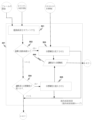
一態様では、遠隔操作手術システム100A,100B(図1A及び図1B)の内視鏡101で取り込まれ、且つ立体視ディスプレイ・ユニット151に表示されるシーンは、組織103と内視鏡101の先端チップとの間の作業距離が変化した場合であっても、一貫した輝度を維持する。遠隔操作手術システム100A,100Bは、内視鏡101が組織に接触したことを自動的に検出し、組織の損傷が生じないように、照明装置110の光パワー出力を調整する。
In one aspect, the scene captured by
照明装置110からの光パワー出力、例えば可視光を有する照明は、時にはチップと呼ばれる内視鏡101の先端チップにおいて内視鏡101から出射される。照明は、組織103から反射され、且つ左側カメラ120Lの左画像センサ121Lによって取り込まれる左カラーシーンを含むフレーム122Lとして、及び右側カメラ120Rの右画像センサ121Rによって取り込まれる右カラーシーンを含むフレームの122Rとして取り込まれる。左右の画像センサ121L,121Rのそれぞれは、シーンを含むフレームを取り込むといえる。
Optical power output from
取り込まれたフレームは、フレーム毎にビデオストリームとしてカメラ制御ユニット130L,130Rに渡され、その制御ユニットで各フレームが処理され、次にビデオ・パイプライン140に渡される。ビデオ・パイプライン140は、以下で説明することを除いて、従来の遠隔操作手術システムにおけるビデオ・パイプラインの処理と同じ方法で各フレームを処理し、次に、そのフレームを外科医コンソール150の立体視ディスプレイ151に渡す。
The captured frames are passed frame by frame as a video stream to
こうして、組織103は、遠隔操作手術システム100A,100Bのユーザによって、外科医コンソール150で視認される。シーンのビデオシーケンスが立体視ディスプレイ151に表示される間に、そのシーンは組織103の連続画像としてユーザに表示され、例えば、ユーザが、組織103の動きを確認し、出血を確認し、呼吸による動作等を確認する。しかしながら、ユーザは、立体視ディスプレイ151に表示されるシーンの輝度の変化に気を取られ、気が散ってしまう可能性がある。遠隔操作手術システム100は、たとえ組織103と内視鏡101の先端チップとの間の作業距離が、増加又は減少のいずれかで変化しても、表示されたシーンの一貫した輝度を維持する。この例では、立体視内視鏡を用いているが、システム100A,100Bは、単一の取り込んだシーンを処理することにより、単一の光チャンネルを有する内視鏡と同じように機能する。
立体視ディスプレイ151に表示されるシーンは、目標輝度と呼ばれる所定の輝度を有する。一態様では、目標輝度は、遠隔操作手術システム100A,100Bによって設定される。しかしながら、いくつかの態様では、外科医は、表示されたシーンの輝度が外科医に許容可能となるように、目標輝度を調整することが許可される。
The scene displayed on
一態様では、内視鏡制御システムは、制御装置を含み、次にこの制御装置は、カメラ制御ユニット130L,130Rと、照明制御装置115とを含む。一態様では、カメラ制御ユニット130L,130Rは、2つの制御ループ131,132を含む(図1A参照)。制御ループ131,132の組合せは、表示されるシーン(表示されるシーンは、取り込まれるフレーム内のシーンである)の目標輝度を維持するように構成され、且つ照明装置の最小出力を維持するように構成される。
In one aspect, the endoscope control system includes a controller, which in turn includes
内視鏡101が組織103から離れる際に、利得及び露出制御ループ131が、左画像センサ121Lによって取り込まれたシーンの、及び右画像センサ121Rによって取り込まれたシーンの全体の輝度が低下するのを検出した場合に、利得及び露出制御ループ131は、カメラ120L,120Rのいずれかに自動的に命令して、カメラ露出時間を増加させ、それによって、続いて取り込まれた画像が目標輝度を有する、又はビデオ・パイプライン140に命令して、ディスプレイ・ユニット151上に表示されるシーンの輝度を制御する利得を増大させ、それによって表示されるシーンが目標輝度有するようになる。いくつかの状況では、利得及び露出制御ループ131は、カメラ露出時間の増加、及びビデオ・パイプラインの利得の増大の両方を自動的に命令する。パワー及び露出制御ループ132は、照明装置110からの光パワー出力を増大すべきかどうかを判断する。光パワー出力が増大した場合に、パワー及び露出制御ループ132は、照明装置110の光パワー出力を増大させ、且つフレーム毎に固定サイズの同期線形ステップにおいてカメラ120L,120Rの露出時間を減少させる。
As
光パワー出力の増大及び露出時間の減少は、同じサイズの変更であり、例えば、光パワー出力の増大が1%であれば、露出時間の減少は1%となる。システムが完全であれば、元の光パワー出力及び元の露出時間で取り込まれたシーンと比較して、新しい光パワー出力及び新しい露出時間で取り込まれたシーンの全体の輝度に変化がないであろう。しかしながら、システムは完全ではないので、新しい光パワー出力及び新しい露出時間で取り込まれたシーンの全体の輝度に変化があり得る。こうして、光パワー出力及び露出時間の同期した変更によって生じる表示画像の輝度のフリッカーが外科医に気付かれないように、固定サイズのステップが選択される。 An increase in optical power output and a decrease in exposure time are changes of the same size, for example, if the increase in optical power output is 1%, the decrease in exposure time is 1%. If the system is perfect, there should be no change in the overall brightness of the scene captured with the new optical power output and new exposure time compared to the scene captured with the original optical power output and original exposure time. Dew. However, since the system is not perfect, there may be a change in the overall brightness of the captured scene with a new optical power output and a new exposure time. Thus, a fixed size step is chosen so that flickering in the brightness of the displayed image caused by synchronized changes in optical power output and exposure time is not noticeable to the surgeon.
同様に、内視鏡101が組織103に向けて移動する際に、利得及び露出制御ループ131が、左側カメラ120Lの左画像センサ121Lによって、及び右側カメラ120Rの右画像センサ121Rによって取り込まれたシーンの輝度の増大を検出した場合に、利得及び露出制御ループ131は、カメラ120L,120Rのいずれかに自動的に命令して、カメラ露出時間を減少させ、それによって、続いて取り込まれる画像が目標輝度を有する、又はビデオ・パイプライン140に命令して、ディスプレイ・ユニット151上に表示されるシーンの輝度を制御する利得を低下させ、それによって表示されるシーンは目標輝度を有する。いくつかの状況では、利得及び露出制御ループ131は、カメラ露出時間の減少、及びビデオ・パイプラインの利得の低下の両方を自動的に命令する。パワー及び露出制御ループ132は、照明装置110からの光パワー出力を低下すべきかどうかを判断する。光パワー出力を低下させる必要がある場合に、パワー及び露出制御ループ132は、照明装置110の光パワー出力を低下させ、且つフレーム毎に固定サイズの同期線形ステップでカメラ120L,120Rの露出時間を増加させる。しかしながら、光パワー出力の低下が最小光パワー出力に達した場合に、照明装置110の光パワー出力は、最小光パワー出力に維持される。
Similarly, as
別の態様では、カメラ制御ユニット130L,130Rは、3つの制御ループ131,132,133を含む(図1B参照)。制御ループ131,132,133の組合せは、表示されるシーン(表示されるシーンは、取り込まれたフレーム内のシーンである)の目標輝度を維持するように構成され、取り込まれたフレームのシーンの飽和画素をそのシーンのそれぞれの所定の画素数未満に制限するように構成され、且つ照明装置の最小出力を維持するように構成される。この態様では、制御ループ131,132は、上述したのと同様に機能する。
In another aspect,
外科医にとって気が散る可能性がある輝度の変化に加えて、その領域の詳細を伝え損ねた、表示されるシーンの領域は、外科医の気をそらす可能性がある。画像センサ121L,121Rは、画素と呼ばれるウェルに光を取り込む。各ウェルは、限られた容量を有し、非常に多くの光がウェルに取り込まれた場合に、そのウェルはオーバーフローし、それによって有用な情報を失う。ウェルがオーバーフローするとき、その画素は、飽和画素と呼ばれる。
In addition to changes in brightness that can be distracting to the surgeon, areas of the displayed scene that fail to convey details in that area can be distracting to the surgeon. The
組織103の領域が非常に多くの光を反射し、組織のその領域によって反射された光を取り込む画素が飽和した場合に、外科医は、その領域を、詳細を含まない明るいスポットとして立体視ディスプレイ151上で見ることになる。その領域の組織、血管等の性質に関するあらゆる情報が失われる。こうして、一態様では、飽和画素制御ループ133は、フレーム全体における飽和画素数を決定し、その飽和画素数が外科医にとって気を散らすのに十分に大きい場合に、飽和画素制御ループ133は、フレームの飽和画素数が外科医の気をそらさないであろう数よりも少なくなるまで、フレーム毎に固定サイズの線形ステップで目標輝度を低下させる。しかしながら、目標輝度の低下は、範囲が限定される。これは、目標輝度が、システムによって設定され又は外科医によって選択された元の目標輝度等の一定割合以下に低下する、例えば目標輝度の最大変化が元の目標輝度の35%未満に制限されることを意味する。こうして、飽和画素制御ループ133は、減少幅の制限を目標輝度に適用するように構成される。
If an area of
飽和画素制御ループ133は、フレーム全体の飽和画素の総数を解析するので、飽和画素制御ループ133の動作は、フレーム内の飽和画素の位置に依存しない。このアプローチは、特徴の位置が表示されるシーンにおいて飽和画素の変化を生じさせる際に、例えば手術用器具がシーン内で動き回る際に、表示されるシーンの一貫性のある輝度を維持する。
Because the saturated
内視鏡101(図1A及び図1B)が組織103に向けて移動し続ける場合に、最終的に、内視鏡101は組織103に接触する。接触は、組織103から反射される輝度に殆ど又は全く変化を生じさせない、光パワー出力レベルの変化を検出することによって観察される。この状況がカメラ制御ユニット130L,130Rによって検出された場合に、照明装置110の光パワー出力は、組織との接触に安全なレベルまで低減される。
As endoscope 101 (FIGS. 1A and 1B) continues to move toward
光パワー出力の変化が、組織103から反射される輝度の変化を殆ど又は全く生じさせない、例えば内視鏡101の先端チップがカニューレ内に引き込まれる場合に、組織接触以外の状況が存在する。誤検出等によって内視鏡101の動作が阻害されるのを防止するために、照明装置101の光パワー出力が組織接触に安全なレベルにされるが、光パワー出力は、既知の方法で変化される。光パワー出力のこの既知の変化が、カメラ制御ユニット130L,130Rによって検出された場合に、内視鏡101は、組織と接触しておらず、光パワー出力の通常制御が、カメラ制御ユニット130L,130Rによって再開される。
Situations other than tissue contact exist, such as when the distal tip of
こうして、一態様では、制御装置は、組織103から反射された輝度を監視することにより、及び光パワー出力を監視することにより、内視鏡のチップと組織との接触を検出する。制御装置は、接触を検出すると、内視鏡のチップからの光パワー出力を減衰させる。反射輝度が直接的に測定されないので、制御装置は、カメラ露出時間に対する取り込んだシーンの全体的な輝度の比として反射輝度を決定する。ここで、全体の輝度は、フレームの平均輝度を示す。
Thus, in one aspect, the controller detects contact between the tip of the endoscope and the tissue by monitoring the brightness reflected from the
こうして、接触を検出するために、制御装置は、反射輝度、すなわちカメラ露出時間に対する取り込んだシーン全体の輝度の比を監視し、且つ内視鏡101からの光パワー出力を監視する。制御装置は、第1の光パワー出力から第2の光パワー出力への変化が、第1の光パワー出力から反射した光によって取り込まれたシーンの比と比較して、比の変化を生じさせない、すなわち反射輝度の変化を生じさせない場合に、内視鏡のチップが組織に接触したと判断する。
Thus, to detect contact, the controller monitors the reflected brightness, ie, the ratio of the brightness of the entire captured scene to the camera exposure time, and monitors the optical power output from the
遠隔操作手術システム100(図1A及び図1B)の一例は、カリフォルニア州サニーベールのIntuitive Surgical, Inc.により市販されているda Vinci(登録商標)最小侵襲性遠隔操作手術システムである。遠隔操作手術システム100A,100Bは、単なる例示であり、これに限定されるものではない。この例では、外科医コンソール250にいる外科医は、ロボットマニピュレータアーム(図示せず)に取り付けられた内視鏡201を遠隔で操作する。da Vinci(登録商標)手術システムに関連する等の他の部品、ケーブル等が存在しているが、これらは、本開示から逸脱するのを避けるために、図1A及び図1Bに示していない。遠隔操作による最小侵襲性手術システムに関する更なる情報は、例えば、(2007年6月13日に出願された、”Minimally Invasive Surgical System”を開示する)米国特許出願第11/762,165号、及び(2001年12月18日に出願された、”Surgical Robotic Tools, Data Architecture, and Use”を開示する)米国特許第6,331,181号に見出すことができ、これら両文献は、参照により本明細書に組み込まれる。
One example of a teleoperated surgical system 100 (FIGS. 1A and 1B) is the da Vinci® minimally invasive teleoperated surgical system, marketed by Intuitive Surgical, Inc. of Sunnyvale, California. Remotely operated
照明システム、例えば照明装置110は、内視鏡101に結合される。一態様では、照明装置110は、光源111及び照明制御装置115を含む。照明制御装置115は、光源111に結合されるとともに、カメラ制御ユニット130L,130Rに結合される。
A lighting system, such as
図1の態様では、光源111は、複数の色成分の照明源112を含む。一態様では、複数の色成分の照明源112は、複数の発光ダイオード(LEDs)を含む。LEDの使用は、単なる例示であり、これ限定されるものではない。複数の色成分の照明源112は、LEDの代わりに、例えば複数のレーザ源又は複数のレーザダイオードで実装することもできる。あるいはまた、光源111は、可視画像のための広帯域白色照明光を生成するために、楕円形のバックリフレクタ及び帯域通過フィルタコーティングを含むキセノンランプを使用することができる。キセノンランプの使用も、単なる例示であり、これに限定されるものではない。例えば、高圧水銀ランプ、他のアークランプ、又は他の広帯域光源を使用してもよい。
In the embodiment of FIG. 1,
この態様では、照明装置110は、組織103を照明するために、立体内視鏡101内の少なくとも1つの照明経路に関連して使用される。照明装置110からの出力光が、コネクタ116に導かれる。コネクタ116は、光を立体内視鏡101内の照明経路に供給し、次にその光を手術部位103に導く。コネクタ116及び立体内視鏡101内の照明経路のそれぞれは、例えば、光ファイバ束、単一の剛性ロッド又は可撓性ロッド、又は光ファイバで実装することができる。一態様では、内視鏡101は、手術部位103から反射した光をカメラ120L,120Rに渡す2つの光チャンネル、すなわち立体視光路も含む。
In this aspect,
カメラ120Lは、左側カメラ制御ユニット130L及びビデオ・パイプライン140により外科医コンソール150の立体視ディスプレイ151に結合される。カメラ120Rは、右側カメラ制御ユニット130R及びビデオ・パイプライン140により外科医コンソール150の立体視ディスプレイ151に結合される。カメラ制御ユニット130L,130Rは、システム・プロセス162から信号を受信する。システム・プロセス162及び中央制御装置160は、システム100内の様々な制御装置の一部を表す。
表示モード選択スイッチ152は、ユーザインターフェイス161に信号を提供し、次に、選択された表示モード、例えばハイパワーモードをシステム・プロセス162に渡す。システム・プロセス162内の各種制御装置は、照明制御装置115を設定し、所望の画像を取得するために、左右のカメラ制御ユニット130L,130Rを設定し、及び外科医が必要とする画像をディスプレイ150に提示するように、取得した画像を処理するのに必要なビデオ・パイプライン140の他の要素を設定する。ビデオ・パイプライン140は、本明細書に提供される詳細を除いて、既知のビデオ・パイプラインと同様である。
Display
中央制御装置160として説明したが、中央制御装置160だけでなく本明細書に記載した他の制御装置のそれぞれが、任意数のモジュールによって実際に実現してもよく、及び各モジュールは、コンポーネントの任意の組合せを含んでもよいことを理解されたい。各モジュール及び各コンポーネントは、ハードウェア、プロセッサ上で実行されるソフトウェア、ファームウェア、又はこれら3つの任意の組合せを含むことができる。また、本明細書に記載されるような中央制御装置160及び他の制御装置のそれぞれの機能及び作用は、1つのモジュールによって実行される、或いは異なるモジュール間で又はさらにモジュールの異なるコンポーネント間で分割してもよい。異なるモジュール又はコンポーネント間で分割する場合に、モジュール又はコンポーネントは、一箇所に集中させてもよく、又は分散型処理のためにシステム100A,100Bに亘って分散させてもよい。こうして、本明細書に記載の中央制御装置160及び他の制御装置のそれぞれは、単一の物理的エンティティを必要とすると解釈すべきではなく、いくつかの態様では、制御装置は、システム100A,100Bに亘って分散させてもよい。
Although described as
図1A及び図1Bでは、カメラ120L,120R及び光源112は、内視鏡101の外部に存在するものとして示されている。しかしながら、一態様では、カメラ120L,120R及び光源112は、内視鏡101の先端チップに含まれる。例えば、図2では、カメラ220及び光源211は、遠隔操作手術システム200の内視鏡201に含まれる。
In FIGS. 1A and 1B,
再び、遠隔操作手術システム200の一例は、上述したda Vinci(登録商標)最小侵襲性遠隔操作手術システムである。遠隔操作手術システム200は、単なる例示であり、これに限定されるものではない。遠隔操作手術システム100A,100Bと同様に、da Vinci(登録商標)手術システムに関連する他の部品、ケーブル等が存在しているが、これらは、本開示から逸脱するのを避けるために、図2に示していない。
Again, one example of a teleoperated
この例では、制御装置は、カメラ制御ユニット230及び照明制御装置215を含む。一態様では、カメラ制御ユニット230は、カメラ制御ユニット130L,130Rを表し、カメラ220は、カメラ120L,120Rを表す。別の態様では、カメラ制御ユニット230は、カメラ220の単一の光チャンネルに結合される。
In this example, the control device includes a
カメラ制御ユニット230は、ディスプレイ・ユニット251に表示されるシーンの輝度を制御する自動露出モジュール232を含む。また、照明制御装置215による光パワー出力制御は、自動露出モジュール232に結び付けられ、外科的なシナリオが最大光パワー出力や照明装置の自動的な増光を必要としない場合で、外科的なシナリオが最小光パワー出力よりも多くの照明を必要とするときに、照明装置の自動調光を提供する。臨床用途では、良好な質のビデオを提供するために必要な多くの光を使用することが望ましい。これは、ハイパワー照明に起因する任意の負の組織相互作用を回避することができる。
標的203、例えば手術部位により反射された光源211からの光は、カメラ220によってカラーシーンとして取り込まれる。光源211は、自動露出モジュール232からのコマンドに応答して及び接触検出モジュール233からのコマンドに応答して、照明制御装置215によって制御される光パワー出力212を有する。標的203は、標的203の明るさの指標である輝度205を有する。通常、光パワー出力212が増減すると、標的203の輝度205も増減する。取り込まれた画像の輝度との混同を避けるために、標的203の輝度は、「反射輝度」と呼ばれ、取り込まれた画像の輝度は、「取込み画像輝度」又は「画像輝度」と呼ばれる。
Light from
一態様では、カメラ220は、ローリングシャッター・カメラである。本明細書で使用される場合に、ローリングシャッタは、カメラの画像センサからフレーム全体を一度に読み出す代わりに、情報が、上から下にフレームの各行から順次読み出されることを意味する。
In one aspect,
カメラ220は、ビデオストリームを含むフレームの連続的なシーケンスを取り込む。取り込んだ各フレームは、標的203の瞬間的な時間のスナップショットであるカラーシーンを含む。ビデオ221は、カメラ220からカメラ制御ユニット230の統計モジュール231にストリーミングされる。統計モジュール231は、ビデオストリームの各フレームに関するリアルタイムの統計情報を収集する。これらの統計情報は、自動露出モジュール232に供給される、フレームの画素輝度のヒストグラムを含む。以下でより完全に説明するように、自動露出モジュール232は、目標輝度、カメラ220の露出時間、ビデオ・パイプライン240の利得、及び内視鏡201からの光パワー出力を制御する。一態様では、自動露出モジュール232は、
ディスプレイ・ユニット251に表示されるビデオ画像の目標輝度を維持し、
カメラ220によって取り込まれた各シーンにおける飽和画素の総数を飽和画素閾値より下に維持し、
カメラ220によって取り込まれるシーンの目標輝度を達成するのに必要な最小光パワー出力(最小限の照明輝度)を維持するように設定される。
maintaining a target brightness of the video image displayed on the
maintaining the total number of saturated pixels in each scene captured by
It is set to maintain the minimum light power output (minimum illumination brightness) necessary to achieve the target brightness of the scene captured by
別の態様では、自動露出モジュール232は、
ディスプレイ・ユニット251に表示されるビデオ画像の目標輝度を維持し、
カメラ220によって取り込まれるシーンの目標輝度を達成するのに必要な最小光パワー出力(最小限の照明輝度)を維持するように設定される。
In another aspect, auto-
maintaining a target brightness of the video image displayed on the
It is set to maintain the minimum light power output (minimum illumination brightness) necessary to achieve the target brightness of the scene captured by
本明細書中で使用される場合に、目標輝度は、ディスプレイ・ユニット251に表示されるシーンの輝度である。時には元の(original)目標輝度と呼ばれる初期目標輝度は、遠隔操作手術システム200において、例えば1500の目標輝度に設定される。しかしながら、一態様では、スライドスイッチが、ディスプレイ・ユニット251上に示されるユーザインターフェイスに提示され、ユーザがユーザにとって許容可能な、表示されるシーンの目標輝度を選択するのを許可する。初期目標輝度は、da Vinci(登録商標)遠隔操作手術システム等の遠隔操作手術システムのユーザからのフィードバックに基づいて、経験的に決定される。以下でより完全に説明するように、目標輝度は、自動露出モジュール232内の制御ループの制御パラメータである。
As used herein, target brightness is the brightness of a scene displayed on
以下でより完全に説明するように、自動露出モジュール232は、シーンの平均輝度が目標輝度に等しくなるのを確実にすることによって、フレーム内の表示されるシーンの一定の輝度を保証する。ここで、シーンの平均輝度は、シーンの全体的な輝度又はフレームの全体的な輝度と呼ばれる。自動露出モジュール232は、減少幅の制限を目標輝度に適用することによって、表示されるシーンにおける飽和画素の影響も制限する。自動露出モジュール232は、ヒステリシスを有する輝度閾値を用いて照明装置210の光パワー出力を制御する。
As described more fully below, auto-
以下でより完全に説明するように、自動露出モジュール232によって実装される制御システムは、ビデオ・パイプラインの利得236及びカメラ露出時間238を制御する。飽和画素が存在しない場合に、取り込んだシーンの全体の輝度の変化は、ビデオ・パイプラインの利得236及びカメラ露出時間238から構成される直線的な関数である。
As described more fully below, a control system implemented by auto-
しかしながら、シーンの飽和画素は、本質的に非線形である。残念ながら、カメラ220及び/又はビデオ・パイプライン240の限定されたビット深さ又は限定されたダイナミックレンジと組み合わされた非常に明るい鏡面反射性のハイライトが、ディスプレイ・ユニット251に表示されるシーンの画素の飽和を生じさせる。また、飽和画素は、飽和画素の領域の詳細が失われるため、画像に望ましくない。
However, saturated pixels in a scene are inherently non-linear. Unfortunately, very bright specular highlights combined with the limited bit depth or limited dynamic range of the
鏡面反射性のハイライトは、高反射性である解剖学的構造から形成され、且つ内視鏡201の視野の間を移動する金属製(高反射性)の器具から形成される。自動露出モジュール232は、器具がシーン全体を移動する際にシーンの輝度変化を最小限に抑え、及び自動露出パラメータのユーザ調整を最小限に抑えるように構成される。
The specular highlight is formed from an anatomical structure that is highly reflective and is formed from a metallic (highly reflective) instrument that moves between the field of view of the
シーン全体を移動する反射性器具の影響を最小限に抑える1つの方法は、遠隔操作手術システム200で利用可能な、器具の最も可能性の高い位置についての空間情報を使用するとともに、器具を配置する可能性がないシーンの領域に自動露出を焦点合わせすることである。1つのアプローチは、シーンの中央に矩形領域を規定することである。この場合に、統計モジュール231は、矩形領域内の画素位置についてのみ画像の統計情報を生成することになる。これは、表示されたシーンの輝度に影響を与えることなく、器具がシーンの周囲を移動するのを可能にする。このアプローチは、器具が大きな可動域を有しておらず、それによって矩形領域を頻繁に移動しない場合に、外科的手処置及び遠隔操作手術システムに有用となり得る。
One way to minimize the effects of reflective instruments moving across a scene is to use the spatial information available in the teleoperated
しかしながら、器具が大きな可動域を有しており、それによって矩形領域を移動する場合に、矩形領域のみの統計情報の使用は、目に見えない障壁(領域の輪郭)を生成し、反射性器具がこの障壁と交差した場合に、自動露出モジュール232が、高反射性器具からの反射によってその領域の増大した輝度を調整するため、シーンの輝度の劇的な変化が生じさせるだろう。目に見えない障壁を横断する器具に関連する輝度の変化は、典型的に外科医の気をそらすため、そのような変化は望ましくない。このため、視認可能なシーン全体の統計情報は、一態様では考慮される。この態様では、フレーム全体を使用して表示されるシーンを生成するので、統計情報は、取り込まれるフレーム全体に対して生成される。別の態様では、表示されるシーンを生成するのに使用されなかった画素は、統計情報を含んでない、例えば、ビデオ処理は、表示されるシーンを取得するために取り込んだフレームをトリミングするので、トリミングされた画素は、統計情報の生成に使用されない。
However, when the instrument has a large range of motion and thereby moves through a rectangular area, the use of statistics only for the rectangular area creates an invisible barrier (area outline) and the reflective instrument intersects this barrier, a dramatic change in scene brightness will occur as the auto-
こうして、一態様では、統計モジュール231は、カメラ220の画像センサによって取り込まれたフレームの全ての画素位置について輝度ヒストグラムを作成する。フレームの各画素位置において、赤、緑、青色画素が存在している。統計モジュール231は、赤、緑、青色画素値を、その画素位置の明るさ、例えば画像輝度に比例した値に変換する。
Thus, in one aspect,
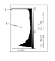
統計モジュール231は、フレーム内で可能な各輝度値を有する画素位置の数をカウントし、ヒストグラムを作成する。輝度が1バイト数で表される場合に、0から255の範囲の256個の可能な輝度値が存在する。図3は、飽和画素を含むフレームの典型的なヒストグラム300を示す。可能な輝度値が、x軸上にプロットされる。各輝度値のバーの高さは、フレーム内でその輝度値を有する画素位置の数を表す。また、x軸に沿って輝度のグレースケール表現が存在している。
統計モジュール231は、フレーム・バッファを必要とせずに取り込んだフレームの統計情報を生成するので、フレームを処理するための追加のストレージを必要としないだけでなく、フレーム・バッファに保存及びこのバッファからの読出しに必要な時間もなくなる。
The
図4は、自動露出モジュール232の一態様のプロセスフロー図である。この態様では、自動露出モジュール232は、時にはプロセス441と呼ばれる飽和画素制限プロセス441、時にはプロセス442と呼ばれる利得及び露出時間調整プロセス442、時にはプロセス443と呼ばれるパワー及び露出時間調整プロセス443を含む。
FIG. 4 is a process flow diagram of one aspect of auto-
自動露出モジュール232は、図1A及び図1Bの3つの制御ループを実装する。第1の制御ループ(飽和画素制御ループ133)は、飽和画素制限プロセス441を含み、第2の制御ループ(利得及び露出制御ループ131)は、利得及び露出時間調整プロセス442を含み、及び第3の制御ループ(パワー及び露出制御ループ132)は、パワー及び露出時間調整プロセス443を含む。自動露出モジュール232によって提供される制御が安定化するように、時定数がこれら3つの制御ループについて選択される。飽和画素制限プロセス441を含む第1の制御ループは、利得及び露出時間調整プロセス442を含む第2の制御ループの時定数よりも長い時定数を有する。パワー及び露出時間調整プロセス443を含む第3の制御ループは、第2の制御ループの時定数よりも長い時定数を有する。図4は、3つのプロセス441,442,443を示しているが、いくつかの態様では、プロセス442,443のみが実施される(図1A参照)。
Auto-
以下でより完全に説明するように、飽和画素制限プロセス441は、飽和画素によって消費されるディスプレイ251の全画面領域を時間の経過とともに最小限に抑えることができる。飽和画素制限プロセス441は、この最小化を実行するために調整済み標的輝度444を制御する。図5Aは、飽和画素制限プロセス441の一態様のプロセスフロー図である。完了すると、飽和画素制限プロセス441は、利得及び露出時間調整プロセス442に移行する。
As described more fully below, the saturated
利得及び露出時間調整プロセス442は、ビデオ・パイプラインの利得及びカメラ露出時間を制御する。利得及び露出時間調整プロセス442は、調整済み目標輝度444に対するフレームの平均輝度の関係に基づいて、ビデオ・パイプラインの利得445及びカメラ露出時間446のいずれかを調整する。ビデオ・パイプラインの利得445は、ビデオ・パイプラインの利得236を提供する。カメラ露出時間446は、カメラ露出時間238を提供する。
A gain and exposure
図5Bは、利得及び露出時間調整プロセス442の一態様のプロセスフロー図である。完了すると、利得及び露出時間調整プロセス442は、パワー及び露出時間調整プロセス443に移行する。
FIG. 5B is a process flow diagram of one aspect of the gain and exposure
パワー及び露出時間調整プロセス443は、照明装置210の光パワー出力及びカメラ露出時間を制御する。カメラ露出時間が第2の露出閾値未満である場合に(図6参照)、光パワー出力が低下され、照明変化を補償するために、正の調整がカメラ露出時間に適用される。カメラ露出時間が第1の露出閾値よりも大きい場合に(図6参照)、照明装置210の光パワー出力が増大され、照明変化を補償するために、負の調整がカメラ露出時間に適用される。こうして、パワー及び露出時間調整プロセス443は、光パワー出力448及びカメラ露出時間調整447の変化が必要であり、その後、次のフレームの処理のために処理を飽和画素制限プロセス441に戻すかどうかを判断する。光パワー出力448は、光パワー出力237を提供する。図5Cは、パワー及び露出時間調整プロセス443の一態様のプロセスフロー図である。
Power and exposure
上記に示したように、図5Aは、飽和画素制限プロセス441の一態様を示す。飽和画素計数プロセス501は、ヒストグラム300の最も高いビン(複数可)の画素数をカウントする。最も高いビン(複数可)、例えばビン255の画素数が飽和画素閾値よりも大きい場合に、過剰飽和画素チェックプロセス502は、目標輝度低下プロセス503に移行し、それ以外は調整済み目標輝度低下チェックプロセス504に移行する。飽和画素計数プロセス501がこの態様では飽和画素制限プロセス441に含まれるものとして示されているが、飽和画素計数プロセス501は、飽和画素制限プロセス441の代わりに、統計モジュール231に含めることができる。
As indicated above, FIG. 5A illustrates one aspect of a saturation
一態様では、時にはプロセス501と呼ばれる飽和画素計数プロセス501は、ヒストグラム300の飽和画素301の数をカウントする。図3の例では、ビン255における飽和画素数は、41873である。
In one aspect, a saturated
内視鏡201が立体内視鏡である場合に、統計モジュール231は、左右の光チャンネルのそれぞれについてヒストグラムを作成する。内視鏡201が立体内視鏡ではない場合に、統計モジュール231は、単一の光チャンネルについてヒストグラムを作成する。一態様では、2バイトを使用して輝度を表すので、ヒストグラムは、x軸に沿って512のビンを有する。一態様では、飽和画素計数プロセス501は、飽和画素数を、左右ヒストグラムのそれぞれのビン511内の画素数の和として決定する。
If
遠隔操作手術システム200のいくつかの動作モードは、左側シーン及び右側シーンの一方を無効としてマークすることができる。これらの動作モードでは、飽和画素のカウントが、有効なシーンのヒストグラムについて行われる。
Some modes of operation of the teleoperated
一態様では、あるシーン内で可能になる飽和画素数についての飽和画素閾値は、経験的に決定した。遠隔操作手術システム200は、ディスプレイ・ユニット251に表示されるシーンの飽和領域の大きさを変化させるように構成した。このようなシステムでの臨床試験は、飽和画素数の閾値及び飽和画素数をカウントするために使用されるビンを決定するために使用され、それによって、システムのユーザがタスクの達成を邪魔や妨害するものとして領域飽和をラベル付けせずに、外科的タスクのセットを行うことができる。
In one aspect, a saturation pixel threshold for the number of saturation pixels possible within a scene was determined empirically. The teleoperated
一態様では、ヒストグラムの(ビン0からビン511までラベル付けされた)512個のビン及び立体内視鏡を用いて、飽和画素閾値は、ビン511で12000として選択される。こうして、この態様について、過剰飽和画素チェックプロセス502は、120000の飽和画素閾値を、統計モジュール231から受信した左ヒストグラムのビン511における飽和画素の総数と右ヒストグラムのビン511における飽和画素の総数との和とを比較した。最大飽和画素数及び飽和画素をカウントするために使用されるビンの数を調整することにより、自動露出モジュール232は、画面上の飽和領域のサイズを調整することができ、且つビデオ・パイプラインにおいて後で利得を補償することができる。フレーム内の飽和画素数が飽和画素閾値よりも大きい場合に、チェックプロセス502は、目標輝度低下プロセス503に移行する。
In one aspect, with 512 bins of the histogram (labeled from
左右のフレームの同じビンにおける飽和画素の総数を使用して、表示されるシーンにおける飽和画素の総面積の尺度を与え、及びその使用は、画面上の飽和画素の位置とは無関係である(すなわち、飽和画素領域は、画素のヒストグラムに殆ど変化を与えずにカメラの視野全体を移動することができる)。それにも拘わらず、飽和画素数が飽和画素閾値を超えた場合に、目標輝度は、目標輝度低下プロセス503により低下される。その結果、飽和画素の大部分は、自動露出モジュール232によって表示されるシーンを暗くさせ、それによってシーンの非反射領域は非常に暗くなる。この理由のために、目標輝度の低下は、範囲が制限される。
The total number of saturated pixels in the same bin of the left and right frames is used to give a measure of the total area of saturated pixels in the displayed scene, and its use is independent of the position of the saturated pixels on the screen (i.e. , the saturated pixel region can be moved across the camera's field of view with little change in the pixel histogram). Nevertheless, if the number of saturated pixels exceeds the saturated pixel threshold, the target brightness is reduced by the target
一態様では、飽和画素制限プロセス441の時定数は、4~5秒であり、目標輝度の最大減少、目標輝度の範囲制限は、元の目標輝度266の35%である。目標輝度の範囲制限は、経験的に決定される。この範囲は、ユーザが識別する表示されるシーンの最小平均輝度を、外科的処置に使用することができる情報を提供するものとして確定するように決定される。元の目標輝度に対する最小平均輝度の比を使用して、例えば以下の式のように、目標輝度の範囲制限を規定する。
目標輝度範囲の制限=(1-(許容可能な最小平均輝度/元の目標輝度))*100
In one aspect, the time constant of the saturation
Target brightness range limit = (1 - (minimum allowable average brightness / original target brightness)) * 100
フレーム当たりの目標輝度の許容変更を決定するために、5秒の時定数及び35%の輝度範囲制限について、毎秒7%の変化が許容される。毎秒60フレームを取り込むカメラについて、フレーム毎の目標輝度の変化は、取り込んだシーンにおける飽和画素数が飽和画素閾値よりも小さい、又は初期標的輝度266からの変化が範囲制限にある、例えば目標輝度が目標輝度の範囲制限だけ低下されるかのいずれかまで、0.11%で固定された線形ステップである。この例では、1500の初期目標輝度及び35%の範囲制限について、目標輝度の制限は、(1500*(1-0.35))であり、975の制限である。 To determine the allowable change in target brightness per frame, a change of 7% per second is allowed for a time constant of 5 seconds and a brightness range limit of 35%. For a camera that captures 60 frames per second, the change in target brightness from frame to frame is due to the number of saturated pixels in the captured scene being less than the saturated pixel threshold, or the change from an initial target brightness of 266 to a range limit, e.g. It is a fixed linear step of 0.11% until either the target brightness is reduced by a range limit. In this example, for an initial target brightness of 1500 and a range limit of 35%, the target brightness limit is (1500*(1-0.35)), which is a limit of 975.
こうして、調整済み目標輝度が目標輝度範囲の制限にない場合に、目標輝度低下プロセス503は、1つの固定サイズの線形ステップにより調整済み目標輝度を変更し、その結果を調整済み目標輝度444として保存する。目標輝度を調整した後に、飽和画素制限プロセス441は、利得及び露出時間調整プロセス442に移行する。調整済み目標輝度が目標輝度範囲の制限にある、すなわち目標輝度が範囲制限されている場合に、目標輝度低下プロセス503は何ら動作せず、プロセス442に移行する。
Thus, if the adjusted target brightness is not within the limits of the target brightness range, the target
最も高いビン(複数可)の画素数が、飽和画素閾値よりも小さい場合に、過剰飽和画素チェックプロセス502は、時にはプロセス504呼ばれる調整済み目標輝度低下チェックプロセス504に移行する。プロセス504は、調整済み目標輝度444を元の目標輝度266と比較する。調整済み目標輝度444が元の目標輝度266よりも小さい場合に、プロセス504は目標輝度増大プロセス505に移行し、それ以外は利得及び露出時間調整プロセス442に移行する。
If the number of pixels in the highest bin(s) is less than the saturated pixel threshold, the oversaturated
目標輝度増大プロセス505は、上記のサイズの1つの固定した線形ステップにより調整後の露出時間を増加させ、その結果を調整済み目標輝度444として保存する。プロセス505は、利得及び露出時間調整プロセス442に移行する。
Target
上記に示したように、図5Bは、利得及び露出時間調整プロセス442の一態様を示す。時にはプロセス511と呼ばれるフレーム平均輝度計算プロセス511は、輝度ヒストグラムから、時には平均輝度と呼ばれる輝度の平均値を決定する。上述したように、内視鏡201が立体内視鏡である場合に、統計モジュール231は、左右の光チャンネルのそれぞれについてヒストグラムを作成する。内視鏡201が立体内視鏡でない場合に、統計モジュール231は、単一のヒストグラムを作成する。こうして、立体内視鏡について、プロセス511は、左側光チャンネルから取り込まれた左側シーンの左平均輝度を決定し、且つ右側光チャンネルから取り込まれた右側シーンの右平均輝度を決定する。左平均輝度及び右平均輝度は、フレーム平均輝度、つまりフレーム全体の輝度を取得するためにプロセス501によって平均化される。フレーム平均輝度計算プロセス511が、この態様では、利得及び露出時間調整プロセス442に含まれるように示されているが、フレーム平均輝度計算プロセス511は、利得及び露出時間調整プロセス442の代わりに、統計モジュール231に含めることができる。
As indicated above, FIG. 5B illustrates one aspect of the gain and exposure
遠隔操作手術システム200のいくつかの動作モードは、左側シーン及び右側シーンの一方を無効としてマークすることができる。これらの動作モードでは、有効なシーンの平均は、プロセス511によってフレーム平均輝度とされる。フレーム平均輝度を決定した後に、プロセス511は、処理を目標輝度に対するフレーム輝度チェックプロセス512に移行する。
Some modes of operation of the teleoperated
時にはチェックプロセス512と呼ばれる目標輝度に対するフレーム輝度チェックプロセス512は、フレーム平均輝度を調整済み目標輝度444と比較する。フレーム平均輝度が調整済み目標輝度444よりも大きい場合に、チェックプロセス512は、利得及び露出時間減少プロセス514に移行する。フレーム平均輝度が調整済み目標輝度444よりも小さい場合に、チェックプロセス512は、利得又は露出時間増加プロセス513に移行する。
A frame brightness check against
処理が、時にはプロセス513と呼ばれる利得又は露出時間増加プロセス513に移行したときに、取り込んだ画像の輝度は低過ぎる。カメラ露出時間が最大カメラ露出時間Emaxでない場合に、プロセス513は、カメラ露出時間を増加させ(図6参照)、次に、続いて取り込んだフレームのフレーム平均輝度を増大させる。しかしながら、カメラ露出時間が最大カメラ露出時間Emaxにある場合に、カメラ露出時間をさらに増加させることはできない。この状況では、プロセス513は、ビデオ・パイプラインの利得を増大させる。
When processing moves to gain or exposure
こうして、プロセス513は、フレームの平均輝度に対する調整済み目標輝度444の比を最初に決定する。フレーム平均輝度が調整済み目標輝度444よりも小さいので、その比は1より大きい。一例として、例えば、輝度を20%だけ増加させる必要がある比1.2を想定する。輝度は、カメラ露出時間の線形関数である。こうして、カメラ露出時間446が最大カメラ露出時間Emaxよりも小さい場合にプロセス513は、カメラ露出時間446を、フレーム平均輝度に対する調整済み目標輝度444の比で乗算し、例えばカメラ露出時間が1.2によって乗算され、その結果が、カメラ露出時間446として保存される。カメラ露出時間446が最大カメラ露出時間Emaxにある場合に、プロセス513は、ビデオ・パイプラインの利得445を、フレーム平均輝度に対する調整済み目標輝度444の比で乗算し、例えばビデオ・パイプラインの利得が1.2によって乗算され、その結果が、ビデオ・パイプラインの利得445として保存される。カメラ露出時間446をフレーム平均輝度に対する調整済み目標輝度444の比で乗算することによって、最大カメラ露出時間Emaxよりも大きいカメラ露出時間を与える場合に、その増加が、カメラ露出時間とビデオ・パイプラインの利得との間で分割され、それによってカメラ露出時間446は、カメラ露出時間のEmaxにあり、増加の残りは、ビデオ・パイプラインの利得445に適用される。例えば20%の増加に伴って、カメラ露出時間446が、最大カメラ露出時間Emaxよりも10%低いである場合に、カメラ露出時間446は、カメラ露出時間446が最大カメラ露出時間Emaxにあり、及びビデオ・パイプラインの利得445が増加の残りによって増大するように、増加される。例えば、
新しいビデオ・パイプラインの利得=1.2*(1.0-0.1)=1.08
完了すると、プロセス513は、パワー及び露出時間調整プロセス443に移行する。
Thus,
New video pipeline gain = 1.2 * (1.0 - 0.1) = 1.08
Once complete,
処理が時にはプロセス514と呼ばれる利得又は露出時間減少プロセス514に移行した場合に、取り込んだ画像の輝度が高過ぎる。ビデオ・パイプラインの利得が1よりも大きい場合に(図6参照)、プロセス514は、ビデオ・パイプラインの利得を低下させ、表示されるシーンの輝度を低下させる。しかしながら、ビデオ・パイプラインの利得が1に等しい場合に、プロセス514は、カメラ露出時間を減少させ、続いて取り込まれる画像のフレーム平均輝度を低下させる。
When processing moves to a gain or exposure
こうして、プロセス514は、フレーム平均輝度に対する調整済み目標輝度444の比を最初に決定する。フレーム平均輝度が調整済み目標輝度444よりも大きいので、その比は1未満である。一例として、例えば、輝度を20%だけ低下させる必要がある比0.8を想定する。
Thus,
ビデオ・パイプラインの利得445が1より大きい場合に、プロセス514は、ビデオ・パイプラインの利得445を、フレーム平均輝度に対する調整済み目標輝度444の比で乗算し、例えばビデオ・パイプラインの利得が0.8によって乗算され、その結果をビデオ・パイプラインの利得445として保存する。ビデオ・パイプラインの利得445が1である場合に、プロセス514は、カメラ露出時間446を、フレーム平均輝度に対する調整済み目標輝度444の比で乗算し、例えばカメラ露出時間が0.8によって乗算され、その結果をカメラ露出時間446として保存する。ビデオ・パイプラインの利得445をフレーム平均輝度に対する調整済み目標輝度444の比で乗算することにより、1未満のビデオ・パイプラインの利得を与える場合に、その減少は、カメラ露出時間とビデオ・パイプラインの利得との間で分割され、それによって、そのビデオ・パイプラインの利得445は、1であり、及びその減少の残りは、カメラ露出時間446に適用される。20%の減少を伴う例について、ビデオ・パイプラインの利得445が1.1である場合に、ビデオ・パイプラインの利得445は1に低下され、カメラ露出時間446は、減少の残り部分を減少させる。例えば、
新しいカメラ露出時間=カメラ露出時間*(1-0.2)/(1/1.1))
完了すると、プロセス514は、パワー及び露出時間調整プロセス443に移行する。
If the
New camera exposure time = camera exposure time * (1-0.2)/(1/1.1))
Upon completion,
パワー及び露出時間調整プロセス443は、照明制御装置215にコマンドを送信することにより、照明装置210の光パワー出力を光源211の所望の光パワー出力に制御し、対応する露出時間調整をカメラ露出時間446に送信する。図7に関連して以下で説明するように、光パワー出力及びカメラ露出時間の変更が同期される。
The power and exposure
図5Cは、パワー及び露出時間調整プロセス443の一態様のプロセスフロー図である。しかしながら、図5Cを検討する前に、図5Cのプロセスで使用されるパラメータについて、検討する。
FIG. 5C is a process flow diagram of one aspect of the power and exposure
一態様では、プロセス443は、固定サイズの同期ステップで光源211からの照明出力の輝度を増減させる。カメラ露出時間は、照明の変化と同じ割合を変化され、例えば、ステップ変化が、照明出力を1.006によって乗算する場合に、カメラ露出時間は、1.006で除算される。
In one aspect,
固定サイズのステップを確実するために、秒単位の立ち上がり時間trampは、光源211からの照明出力を最小光パワー出力Pminから最大光パワー出力Pmaxに直線的に立ち上げる、及び逆にするために使用される期間として特定される。
To ensure a fixed size step, the rise time tramp in seconds is used to linearly ramp up and reverse the illumination output from the
固定サイズの光パワー出力ステップPstepは、次のように規定される。
Pstep=(Pmax-Pmin)/(tramp*(フレーム/カメラの秒))。
A fixed size optical power output step Pstep is defined as follows.
Pstep=(Pmax-Pmin)/(tramp*(frames/camera seconds)).
一例として、800ミリワット(mW)の最大光パワー出力、400mWの最小光パワー出力、3秒の立ち上がり時間tramp、毎秒60フレームを取り込むカメラについて検討する。光パワー出力が変化した場合に、固定サイズのステップは、+/-2.22mW/フレームである。現在の光パワー出力が400mWである場合に、照明出力が(1+(2.22/400))によって乗算され、つまり1.0056となる。こうして、カメラ露出時間は、1.0056で除算される。 As an example, consider a camera that has a maximum optical power output of 800 milliwatts (mW), a minimum optical power output of 400 mW, a 3 second rise time tramp, and captures 60 frames per second. When the optical power output is changed, the fixed size step is +/-2.22 mW/frame. If the current optical power output is 400 mW, the illumination power is multiplied by (1+(2.22/400)), or 1.0056. Thus, the camera exposure time is divided by 1.0056.
上記に示したように、照明の変化は、表示されたシーンに目立つフリッカーを生成してはならない。こうして、立ち上がり時間は、照明の変化が、ディスプレイ・ユニット251に表示されるシーンに目立つ輝度フリッカーを生じないように、及び3つの制御ループが安定する、例えば、立ち上がり時間が第3の制御ループの時定数となるように、選択される。こうして、これらの実施例では、第1の制御ループの時定数は、5秒であり、第3の制御ループの時定数は、3秒である。
As indicated above, changes in illumination must not produce noticeable flicker in the displayed scene. In this way, the rise time is such that changes in illumination do not cause noticeable brightness flicker in the scene displayed on the
内視鏡201の先端チップにおける新しい光パワー出力Pnewは、現在の光パワー出力Pcurrentプラス又はマイナス光パワー出力ステップPstepである。すなわち、
Pnew=Pcurrent+/-Pstep
ここで、この例では、光パワー出力ステップPstepは、0、+2.22、又は-2.22である。以下で説明するように、光パワー出力ステップPstepの3つの可能な値のうちのいずれかが、カメラ露出時間の値に依存して使用される。また、図7に関連して以下でより完全に説明するように、光パワー出力及び露出時間の変化は、パイプラインのフレーム時間に同期される。
The new optical power output Pnew at the distal tip of the
Pnew=Pcurrent+/-Pstep
Here, in this example, the optical power output step Pstep is 0, +2.22, or -2.22. As explained below, any of the three possible values of the optical power output step Pstep are used depending on the value of the camera exposure time. Also, as described more fully below in connection with FIG. 7, changes in optical power output and exposure time are synchronized to the frame time of the pipeline.
フレーム当たりの光パワー出力のステップ変化が既知であるが、照明制御装置215は、光源がLEDである場合に、複数の光源211の各光源への電流を制御する。しかしながら、LEDの光パワー出力は、電流の変化に対して線形ではない。こうして、ルックアップテーブルを使用して、光パワー出力の命令された変化を各LEDの電流に変換し、それによって光パワー出力が、内視鏡201の先端チップに提供される。
Although the step change in optical power output per frame is known, the
ルックアップテーブルの値は、既知の基準に対する光源211の較正によって決定される。光パワー出力(部)が内視鏡201の先端チップにあるので、各LEDの電流は、光源211の実際の出力が、光源211の出力と内視鏡201の先端チップとの間の光のあらゆる減衰を考慮するために、十分高くなるように決定される。
The lookup table values are determined by calibrating the
一態様では、最大光パワー出力Pmaxは、内視鏡201の先端チップと標的203との間の最小作業距離において、最大光パワー出力Pmaxが組織に損傷を生じさせないように選択される。
In one aspect, the maximum optical power output Pmax is selected such that at a minimum working distance between the distal tip of the
最小光パワー出力Pminは、内視鏡201の先端チップと標的203との間の最小作業距離において、表示されるシーンのノイズが閾値を下回り、光パワー出力が照明装置210の達成可能な最小光パワー出力を超えるように選択される。
The minimum optical power output Pmin is defined as the minimum working distance between the distal tip of the
照明出力の変化が増大、減少、又は同じ値に留まるかどうかを確認するために、カメラ露出時間の値を使用する。取り込んだシーンの平均輝度が高い場合の第3領域603(図6参照)の非常に小さなカメラ露出時間では、光パワー出力が減光される。具体的には、第3領域603のカメラ露出時間を有する連続する各フレームについて、光パワー出力が、光パワー出力Pstepによって低減され、及びカメラ220の露出時間は、光パワー出力の減少率と同じ割合で増加される。光パワー出力ステップPstepが、最小光パワー出力Pminを下回るように照明出力を低下させる場合に、照明出力は変化せず、照明出力は、最小光パワー出力Pminに維持され、カメラ220の露出時間は、変更されない。
Use the camera exposure time value to see if the change in illumination output increases, decreases, or stays the same value. For very small camera exposure times in the third region 603 (see FIG. 6) when the average brightness of the captured scene is high, the optical power output is dimmed. Specifically, for each successive frame having a camera exposure time of the
露出時間の増加及び照明の対応する減少は、以前取り込まれた画像と略同じ平均輝度で取り込まれた画像を生じさせ、カメラ露出時間は、第2の領域602に向けて増加すると想定する。
Assume that the increase in exposure time and corresponding decrease in illumination results in a captured image with approximately the same average brightness as the previously captured image, and that the camera exposure time increases towards the
取り込んだシーンの平均輝度、シーン全体の輝度が低い場合の第1の領域601の非常に高いカメラ露出時間では、光パワー出力が増大される。具体的には、第1の領域601の露出時間を有する連続する各フレームについて、光パワー出力は、光パワー出力のステップPstepによって増大され、カメラ220の露出時間は、光パワー出力の増加率と同じ割合で減少される。光パワー出力の変化が、最大光パワー出力Pmaxを上回るように照明出力を増大させる場合に、照明出力は、変化されず、及び照明出力は、最大光パワー出力Pmaxに維持され、カメラ220の露出時間は、変更されない。
At very high camera exposure times in the
露出時間の減少及び照明の対応する増加は、以前取り込んで画像と略同じ平均輝度で取り込まれた画像を生じさせ、カメラ露出時間は、第2の領域602に向けて減少すると想定する。
Assume that a decrease in exposure time and a corresponding increase in illumination results in a captured image with approximately the same average brightness as the previously captured image, and that the camera exposure time decreases toward the
こうして、パワー及び露出時間調整プロセス443を含む制御ループは、照明出力が第2の領域602によって表されるような照明出力範囲に向けて進むように照明を変化させる。第2の領域602は、ヒステリシス領域である。
Thus, the control loop including the power and exposure
可能な限り、照明の変化を最小限に抑えることが望ましい。内視鏡201の先端チップと標的203との間の平均作業距離に位置する、照明変化に関連する輝度の変化は、シーンの一部に亘って外科医に気付かれないかもしれないが、平均作業距離よりも大きいシーンの位置において、外科医は、気が散るような輝度の変化に気づく傾向にある。従って、この態様では、照明及び露出変化がカメラ露出時間の変化と伴に実施されない第2の領域602は、可能なカメラ露出時間の範囲の50%が割り当てられる。本開示に鑑みて、第2の領域602の範囲は、可能なカメラ露出時間の範囲の50%以外の割合として選択することができる。
It is desirable to minimize changes in lighting whenever possible. Changes in brightness associated with illumination changes located at the average working distance between the distal tip of the
こうして、図6に示されるように、パワー及び露出時間調整プロセス443は、カメラ露出時間の値に基づいて、光パワー出力及びカメラ露出時間を設定する。第3の制御ループ、パワー及び露出制御ループ132は、カメラ露出時間が第1の露出閾値よりも大きい場合に、光パワー出力が最大光パワー出力Pmax未満であれば、照明出力を増大させ、且つカメラ露出時間を減少させる。第3の制御ループは、カメラ露出時間が第2の露出閾値よりも小さい場合に、光パワー出力が最小光パワー出力Pminよりも大きければ、光パワー出力を低下させ、且つカメラ露出時間を増加させる。第3の制御ループは、露出時間が第1の露出閾値と第2の露出閾値との間にある場合に、光パワー出力及びカメラ露出時間を変化させないままにする。
Thus, as shown in FIG. 6, the power and exposure
一態様では、最大光パワー出力Pmaxは、光パワー出力800mWに対応する。最小光パワー出力Pminは、400mWの光パワー出力に対応し、最大カメラ露出時間Emaxは、4096であり、最小カメラ露出時間Eminは、ゼロである。 In one aspect, the maximum optical power output Pmax corresponds to an optical power output of 800 mW. The minimum optical power output Pmin corresponds to an optical power output of 400 mW, the maximum camera exposure time Emax is 4096, and the minimum camera exposure time Emin is zero.
図5Cに進むと、時にはプロセス521と呼ばれる第2の閾値未満の露出時間チェックプロセス521は、カメラ露出時間446が第2の露出閾値未満であるかどうかを判断する。カメラ露出時間446が第2の露出閾値未満である場合に、プロセス521は、処理を照明低下及び露出時間増加プロセス523に移行させ、それ以外は処理を第1の閾値未満の露出時間チェックプロセス522に移行する。
5C, a second exposure time below
処理が時にはプロセス523と呼ばれる照明低下及び露出時間増加プロセス523に移行した場合に、カメラ露出時間446は、第3領域603にある。従って、照明出力が最小光パワー出力Pminよりも大きければ、プロセス523は、光パワー出力ステップPstepによって、光パワー出力448、例えば光パワー出力Pcurrentを減少させる。プロセス523は、カメラ露出時間調整447に段階的増加をロード(load)し、次にカメラ露出時間446を増加させる。照明出力が最小光パワー出力Pminに等しい場合に、プロセス523は、動作を実行しない。照明低下及び露出時間増加プロセス523は、処理を飽和画素制限プロセス441に移行させる。
チェックプロセス521が処理を第1の閾値未満の露出時間チェックプロセス522に移行させる場合に、チェックプロセス522は、カメラ露出時間446が第1の露出閾値未満であるかどうかを判断する。カメラ露出時間446が第1の露出閾値未満である場合に、チェックプロセス522は、処理を照明増大及び露出時間減少プロセス524に移行させ、それ以外は処理を飽和画素制限プロセス441に移行させる。
If
処理が、時にはプロセス524と呼ばれる照明増大及び露出時間減少プロセス524に移行した場合に、カメラ露出時間446は、第1の領域601にある。従って、照明出力が最大光パワー出力Pmax未満である限り、プロセス524は、光パワー出力ステップPstepにより、光パワー出力448、例えば光パワー出力Pcurrentを増大させる。プロセス524は、カメラ露出時間調整447に段階的に減少するようロードされ、次にカメラ露出時間446を減少させる。光パワー出力が最大光パワー出力Pmaxと等しい場合に、プロセス524は、動作を実行しない。照明増大及び露出時間減少プロセス524は、処理を飽和画素制限プロセス441に移行させる。
パワー及び露出時間調整プロセス443が終了すると、処理は飽和画素制限プロセス441に戻る。こうして、プロセス441~443が取り込んだ各フレームについて繰り返される。
Once the power and exposure
照明変化を遠隔操作手術システム200のユーザに見えないようにするために、照明の変化は、カメラ露出時間の変化の補償と同期され、それによって外科医に表示されるビデオの全体の輝度が、照明の変化を略一定のままにする。例えば、光パワー出力の低下及びカメラ露出時間の増加は、同じビデオフレームで生じさせなければならない。ここでは、略一定は、遠隔操作手術システム200の許容範囲内で一定であることを意味する。
To make the illumination changes invisible to the user of the teleoperated
遠隔操作手術システム200でのビデオストリームの処理は、遅延される。照明制御、ビデオ・パイプラインの利得制御、カメラの露出制御、ビデオ統計的な収集及び解析は全て、異なるパイプライン遅延となる。例えば、ビデオストリームの第1フレーム701のフレーム時間t0(図7)において、フレームが取り込まれ、統計情報が、統計モジュール231によってフレーム701について収集され、以前に取り込んだフレームからの利得が、ビデオ・パイプラインに書き込まれる。
Processing of the video stream at teleoperated
フレーム時間t1において、照明出力及びカメラ露出時間が、自動露出モジュール232によって計算され、カメラ露出時間は、カメラ220に書き込まれる。フレーム時間の開始時t2において、光パワー出力が新しい光パワー出力Pnewに変化する。フレーム702が、カメラによってフレーム時間t3において第1のフレーム701を使用して生成される露出時間及び光パワー出力で取り込まれる。こうして、新たな露出時間及び光パワー出力が、フレーム702の取込みについて同期される。
At frame time t1, the illumination power and camera exposure time are calculated by
これらのステップは、露出時間及び照明装置の輝度が、ビデオの各フレームに適用されるように、パイプライン化される。一態様では、パイプラインの同期は、ビデオストリームで、システム200全体に亘って移動するビデオフレーム同期信号にメタデータを追加する、すなわちビデオストリームの各フレームにメタデータを取り付けることによって達成される。メタデータは、カメラ露出時間、照明装置の輝度、及びビデオ・パイプラインの利得を含む。
These steps are pipelined so that the exposure time and lighting device brightness are applied to each frame of the video. In one aspect, pipeline synchronization is accomplished by adding metadata to a video frame synchronization signal that travels throughout
一態様では、遠隔操作手術システムは、外科医のコマンドによって手術野の照明を増大させる方法と、組織と内視鏡201との間の接触を検出するための方法とを含む。組織接触が検出される場合に、内視鏡201からの照明は、組織との接触に安全なレベルまで自動的に低減される。
In one aspect, a teleoperated surgical system includes a method for increasing illumination of a surgical field at the command of a surgeon and a method for detecting contact between tissue and
ディスプレイ・ユニット251に表示されるシーンの信号対雑音比は、照射標的203からカメラ220の画像センサに反射して戻された光が減少すると、低下する。信号対雑音比のこの減少は、内視鏡201の使用可能な作業距離204(内視鏡のチップとイメージング標的203との間の距離)を制限する可能性がある。
The signal-to-noise ratio of the scene displayed on
しかしながら、光パワー出力レベルと組織損傷の危険性との間にトレードオフが存在する。述べたように、増大した光パワー出力は、使用可能な作業距離204の増加をもたらすことができる。しかしながら、増大した光パワー出力は、光パワー出力が十分に高い場合に、組織損傷の危険性も増大させる可能性があり、作業距離は、入射光が損傷レベルを超えないように、十分に小さくされる。組織損傷の増大した危険性は、入射光の増大した光パワー密度によって、又は温度上昇した内視鏡のチップが組織に接触することによってのいずれかで生じる可能性がある。いずれの場合も、光パワー出力レベルを低くすることによって、危険性が殆ど無くなる。
However, a trade-off exists between optical power output level and risk of tissue damage. As mentioned, increased optical power output can result in an increase in the
組織損傷の危険性を回避するために、内視鏡201からの光パワー出力レベルは、光パワー出力レベルが、内視鏡のチップと組織との間の直接的な接触について安全となるように制限される。しかしながら、これは、内視鏡201の最大作業距離を制限する。例示の目的のために、1W未満の光パワー出力レベルは典型的に安全であると考えられる。しかしながら、一態様では、遠隔操作手術システム200は、光パワー出力が安全な光パワー出力よりも大きい、例えば1.5W等の1Wワットより大きい光パワー出力であるハイビームの動作モードを含む。
To avoid the risk of tissue damage, the optical power output level from
一態様では、時にはハイパワー動作モードと呼ばれるハイビームの動作モードは、外科医によって外科医コンソール上の物理的なスイッチ265を活性化することで開始される。別の態様では、ハイビームの動作モードは、外科医がディスプレイ・ユニット251に示されるユーザインターフェイスに提示されるスイッチをクリックすることによって開始される。
In one aspect, the high beam mode of operation, sometimes referred to as the high power mode of operation, is initiated by the surgeon by activating a
外科医がハイビームモードで制御する際に、ハイビームの動作モードは、この動作モードでは光パワー出力が安全と考えられる出力よりも大きいため、組織損傷のリスクが低い場合にのみ、活性化する必要がある。腹部手術の手術野を検査することは、ハイビームの動作モードの一般的な用途になる。しかしながら、外科医が内視鏡201を組織の極近くに不意に移動させる危険性、又は組織との意図しない接触の危険性が依然として存在する。
When the surgeon controls the high beam mode, the high beam mode of operation should only be activated when the risk of tissue damage is low, as the optical power output is greater than that considered safe in this mode of operation. . Inspecting the surgical field in abdominal surgery becomes a common application for the high beam mode of operation. However, there is still a risk of the surgeon inadvertently moving the
内視鏡201が組織の極近くに不意に移動した場合に、上記で説明したように、取り込んだ画像の平均輝度が増大し、それによって自動露出モジュール232は、カメラ露出時間を減少させる。カメラ露出時間が減少し続けると、露出時間が第3領域603に達する。次に、自動露出モジュール232は、光パワー出力の低減を開始する。こうして、内視鏡201を組織の極近くに不意に移動させることによる照明の増大は、自動露出モジュール232によって自動的に処理され、光パワー出力を低減させる。
If the
内視鏡201が組織に接触した場合に、その接触は、接触検出モジュール233によって検出され、照明は、通常の動作モード又はハイビームの動作モードのいずれかで、適切なレベルまで低下される。接触検出モジュール233は、光パワー出力の変化(増減)が、標的203から反射された光の平均輝度の対応する変化を生じないことを検出することにより、組織接触を判定し、ここで平均の反射輝度は、カメラ露出時間で除算された取込みシーンの平均輝度とされる。シーンの平均輝度が、フレーム平均輝度計算プロセス511(図5C)によって決定され、カメラ露出時間は、カメラ露出時間446で利用可能である。あるいはまた、フレーム平均輝度計算プロセス511(図5C)は、接触検出モジュール233又は統計モジュール231に組み込むことができる。
When the
例えば、内視鏡のチップが覆われている、すなわち組織と接触しており、それによって光がカメラレンズに入射しない場合に、自動露出モジュール232は、光パワー出力を増大させる。しかしながら、組織接触は、依然として反射光がカメラに到達するのを阻止する。その結果、光パワー出力が増大したときに、平均反射輝度に変化はない。こうして、接触検出モジュール233は、組織接触を検出し、組織接触に安全なレベルまで光パワー出力を減衰させる。一態様では、組織との接触に安全な光パワー出力は、最小光パワー出力よりも大きい。しかしながら、組織の損傷が、内視鏡のチップと組織との間の接触による伝導熱によって支配される場合に、組織との接触に安全な光パワー出力は、最小光パワー出力以下であってもよい。
For example, the auto-
一態様では、接触検出モジュール233は、自動露出モジュール232の光パワー出力制御を無効にし、照明制御装置215に命令して、光パワー出力を安全なレベルまで低下させる。あるいはまた、接触検出モジュール233は、照明制御装置215に命令して、光源211の減衰器を起動させ、光源211からの光パワー出力を安全なレベルに低下させることができる。
In one aspect,
一態様では、組織接触検出は、次のように実施される。
dL/dI=0
ここで、dLは、2つの取り込んだフレームの平均の反射輝度の変化であり、
dIは、2つの取り込んだフレームの光パワー出力の変化である。
In one aspect, tissue contact detection is performed as follows.
dL/dI=0
Here, dL is the change in the average reflected luminance of the two captured frames,
dI is the change in optical power output between two captured frames.
別の態様では、接触は、以下に示されるときに検出される。
-閾値<dL/dI<閾値
ここで、閾値は、dL及びdIの測定における測定の不確実性及びノイズを包含する。
In another aspect, contact is detected as indicated below.
- Threshold<dL/dI<Threshold where the threshold encompasses measurement uncertainty and noise in the measurement of dL and dI.
こうして、接触検出方法は、変動する光パワー出力を利用する。動的な照明制御を備えたシステムでは、光パワー出力は、内視鏡のチップが組織に近づくと変化する。自動露出制御は、組織が内視鏡201のチップに近づくと、光パワー出力を低下させる。一旦組織が内視鏡201のチップに接触すると、反射輝度の変化は、光パワーを変化させても殆ど又は全く検出されない。この状態を検出すると、照明装置の輝度は、組織接触に安全である所定のレベル、例えば照明Pminまで、減衰、すなわち低下される。
Thus, the touch detection method utilizes varying optical power output. In systems with dynamic illumination control, the optical power output changes as the endoscope tip approaches tissue. Automatic exposure control reduces optical power output as tissue approaches the tip of
別の態様では、光パワー出力の変化に伴う反射輝度の変化を監視する代わりに、組織が内視鏡のチップに接触する際の反射輝度プロファイル全体の特性が、接触検出、又は改善された接触検出に使用される。反射輝度プロファイル全体の特性は、時間ドメイン又は周波数ドメインのいずれかとすることができる。取り込まれたシーンから決定された平均反射輝度が、閾値範囲内の輝度プロファイル全体の特性と一致する場合に、接触が検出される。一態様では、反射輝度プロファイル全体の特性は、内視鏡のチップが組織に近づき且つ接触する際に、シーンの全体的な反射輝度を測定することによって経験的に決定される。 In another aspect, instead of monitoring changes in reflected brightness with changes in optical power output, characteristics of the overall reflected brightness profile as tissue contacts the tip of an endoscope are used for contact detection or improved contact detection. used for detection. The characteristics of the overall reflected brightness profile can be either time domain or frequency domain. A touch is detected if the average reflected brightness determined from the captured scene matches the characteristics of the entire brightness profile within the threshold range. In one aspect, the characteristics of the overall reflected brightness profile are determined empirically by measuring the overall reflected brightness of the scene as the tip of the endoscope approaches and contacts tissue.
接触する組織の除去が反射輝度の変化を生じさせない場合に、システム200が、低輝度状態でスタック(stuck)している状況である可能性がある。照明装置210の光パワー出力が変化しない「スタック」状態を避けるために、低速度の光パワー出力ディザリング(dithering)技術を採用している。組織接触が検出された場合に、接触検出モジュール233は、ディザリング・モジュール217を有効にする。ディザリング・モジュール217は、非接触状態を検出する信頼性を高めるために、安全レベルに関する既知の方法で光パワー出力を変化させる。
If removal of the contacting tissue does not result in a change in reflected brightness, there may be a situation where the
例えば、ディザリング・モジュール217は、光源211からの光パワー出力を安全レベルに関して既知の時間依存性の方法、例えば正弦波方法で変化させることができる。時間依存性の低レベル反射パワー出力がカメラに到達した場合に、自動露出モジュール232は、光パワー出力の変化を検出する、例えば、内視鏡201のチップが組織と接触しなくなることを意味する、取り込んだシーンの平均輝度の変化を検出する。こうして、接触検出モジュール233は、自動露出モジュール232が、光パワー出力の制御を行うように、リセットされる。
For example, dithering module 217 may vary the optical power output from
本明細書で説明する様々なモジュールは、プロセッサ、ハードウェア、ファームウェア、又はこれら3つの任意の組合せで実行されるソフトウェアにより実現することができる。モジュールがプロセッサ上で実行されるソフトウェアとして実現される場合に、ソフトウェアは、コンピュータ可読命令としてメモリに格納され、コンピュータ可読命令は、プロセッサで実行される。メモリの全部又は一部は、プロセッサがメモリに結合される限り、プロセッサとは異なる物理的な位置にあってもよい。メモリは、揮発性メモリ、不揮発性メモリ、又はそれら2つのメモリの任意の組合せを指す。 The various modules described herein can be implemented by software running on a processor, hardware, firmware, or any combination of the three. When a module is implemented as software running on a processor, the software is stored in memory as computer-readable instructions and the computer-readable instructions are executed on the processor. All or part of the memory may be in a different physical location from the processor, so long as the processor is coupled to the memory. Memory refers to volatile memory, non-volatile memory, or any combination of the two.
また、本明細書に記載されるように、様々なモジュールの機能は、1つのユニットによって実行される、或いは異なるコンポーネント又は異なるモジュール間で分割することができ、各機能は、次に、ハードウェア、プロセッサ上で実行されるソフトウェア、及びファームウェアの任意の組合せによって実施することができる。異なるコンポーネント間で分割する場合に、コンポーネントは、一箇所に集中させてもよく、又は分散型処理のためにシステム200に亘って分散させてもよい。様々なモジュールの実行は、様々なモジュールについて上述した処理を実行する方法を生じさせる。
Also, as described herein, the functions of the various modules may be performed by one unit or divided among different components or different modules, each function then being implemented by the hardware , software running on a processor, and firmware. When partitioned between different components, the components may be centralized in one location or distributed throughout
プロセッサは、プロセッサによって実行される命令を含むメモリに結合される。これは、コンピュータシステム内で、或いは、モデム及びアナログライン又はデジタルインターフェイス及びデジタルキャリアラインを介して他のコンピュータとの結合を介して達成することができる。 A processor is coupled to memory that contains instructions executed by the processor. This can be accomplished within the computer system or through coupling to other computers via modems and analog lines or digital interfaces and digital carrier lines.
ここで、コンピュータプログラム製品は、本明細書に記載したプロセスの一部又は全てに必要なコンピュータ可読コードを格納するように構成された、又はそれらのプロセスの一部又は全てのコンピュータ可読コードが格納されたコンピュータ可読媒体を含む。コンピュータプログラム製品のいくつかの例は、CD-ROMディスク、DVDディスク、フラッシュメモリ、ROMカード、フロッピー(登録商標)ディスク、磁気テープ、コンピュータハードドライブ、ネットワーク上のサーバー、及びコンピュータ可読プログラムコードを表す、ネットワークを介して送信される信号である。非一時的な有形のコンピュータプログラム製品は、プロセスの一部又は全てのコンピュータ可読命令を格納するように構成された、又はプロセスの一部又は全てのコンピュータ可読命令が格納された有形のコンピュータ可読媒体を含む。非一時的な有形のコンピュータプログラム製品は、CD-ROMディスク、DVDディスク、フラッシュメモリ、ROMカード、フロッピー(登録商標)ディスク、磁気テープ、コンピュータハードドライブ、及び他の物理的記憶媒体である。 where the computer program product is configured to store computer readable code necessary for some or all of the processes described herein, or contains computer readable code for some or all of the processes described herein. computer-readable media. Some examples of computer program products represent CD-ROM disks, DVD disks, flash memory, ROM cards, floppy disks, magnetic tape, computer hard drives, servers on networks, and computer readable program code. , is a signal sent over a network. A non-transitory tangible computer program product is a tangible computer-readable medium configured to store or having computer-readable instructions for some or all of a process stored thereon. including. Non-transitory tangible computer program products are CD-ROM disks, DVD disks, flash memory, ROM cards, floppy disks, magnetic tape, computer hard drives, and other physical storage media.
本開示に鑑みて、本明細書で説明したプロセスの一部又は全てに使用される命令は、ユーザにとって関心のあるオペレーティングシステム及びコンピュータプログラム言語を使用して広範なコンピュータシステム構成で実装することができる。 In view of this disclosure, the instructions used for some or all of the processes described herein may be implemented on a wide variety of computer system configurations using operating systems and computer programming languages of interest to the user. can.
本発明の態様及び実施形態を示す上述した詳細な説明及び添付の図面は、限定するものと解釈すべきではなく、特許請求の範囲が、保護される発明を規定する。種々の機械的な、組成的な、構造的な、電気的な、及び操作上の変更は、本明細書及び特許請求の範囲の精神及び範囲から逸脱することなく行うことができる。いくつかの例では、周知の回路、構造、及び技術は、本発明を不明瞭にすることを避けるために詳細に示していない又は説明していない。 The foregoing detailed description and accompanying drawings illustrating aspects and embodiments of the invention should not be construed as limiting, and the following claims define the protected invention. Various mechanical, compositional, structural, electrical, and operational changes may be made without departing from the spirit and scope of the specification and claims. In some instances, well-known circuits, structures, and techniques are not shown or described in detail to avoid obscuring the present invention.
また、この詳細な説明の用語は、本発明を限定するものではない。例えば、「~の下に(beneath)」、「~より下の(below)」、「~の下方の(lower)」、「~より上の(above)」、「~の上方の(upper)」、「基端の(proximal)」、「先端の(distal)」等の空間に関連する用語は、図に示される1つの要素又は機構に対する別の要素又は機構との関係を説明するために使用される。これらの空間に関連する用語は、図面に示される位置及び向きに加えて、使用又は操作中の装置の異なる位置(すなわち、配置)及び向き(すなわち、回転位置)を包含することを意図している。 Moreover, the terminology in this detailed description is not intended to limit the invention. For example, "beneath", "below", "lower", "above", "upper" Spatial terms such as "," "proximal," and "distal" are used to describe the relationship of one element or feature to another shown in a figure. used. These space-related terms are intended to encompass different positions (i.e., configurations) and orientations (i.e., rotational positions) of the device during use or operation in addition to the positions and orientations shown in the drawings. There is.
例えば図面内の装置をひっくり返した場合に、他の要素又は機構「より下の(below)」又は「の下に(beneath)」として説明された要素は、次に、他の要素又は機構「より上の(above)」又は「の上に(over)」となる。従って、例示的な用語「~より下の(below)」は、「~より上の(above)」及び「~より下の(below)」両方の位置及び向きを包含することができる。その装置は、他の方法で向き合わせ(90度回転又は他の向きに)してもよく、本明細書で使用される空間に関連する説明は、それに応じて解釈される。 For example, if the device in the drawings is turned over, elements described as "below" or "beneath" other elements or features may then be "beneath" other elements or features. ``above'' or ``over.'' Thus, the exemplary term "below" can encompass both "above" and "below" positions and orientations. The device may be oriented in other ways (rotated 90 degrees or in other orientations) and the spatially related descriptions used herein are interpreted accordingly.
同様に、様々な軸線に沿った及びこの軸線周りの運動の説明は、装置の様々な特別な位置及び向きを含む。単数形「1つの(a, an)」及び「その(the)」は、文脈が他に指示しない限り、複数形も含むことを意図している。用語「備える、有する、含む(comprises, comprising)」、「含む、有する(including)」等は、説明した特徴、ステップ、操作、要素、及び/又は構成要素の存在を特定するが、1つ以上の他の特徴、ステップ、操作、要素、構成要素、及び/又はグループの存在又は追加を排除するものではない。 Similarly, descriptions of motion along and about various axes include various particular positions and orientations of the device. The singular forms "a, an" and "the" are intended to include the plural unless the context dictates otherwise. The terms "comprises, comprising," "including" and the like identify the presence of the described feature, step, operation, element, and/or component, but not one or more of the described features, steps, operations, elements, and/or components. This does not exclude the presence or addition of other features, steps, operations, elements, components and/or groups.
「結合した」として説明した構成要素は、電気的に又は機械的に直接的に結合されるか、又は1つ以上の中間部品を介して間接的に結合してもよい。本開示に鑑みて、向上したディスプレイシステムに関して説明した操作のいずれか又は任意の組合せで使用される命令は、ユーザにとって関心のあるオペレーティングシステム及びコンピュータプログラム言語を使用して広範なコンピュータシステム構成で実施することができる。 Components described as "coupled" may be electrically or mechanically coupled directly, or indirectly via one or more intermediate parts. In view of this disclosure, the instructions used in any or any combination of the operations described with respect to the enhanced display system may be implemented on a wide variety of computer system configurations using operating systems and computer programming languages of interest to the user. can do.
全ての実施例及び説明の参照は、非限定的であり、特許請求の範囲を本明細書で説明した特定の実装態様や実施形態及びその等価物に限定するために使用すべきではない。見出しは、単に形式のためであり、1つの見出しの下のテキストは、相互参照することができ、すなわち1つ以上の見出しの下のテキストに適用することができるので、主題をあらゆる方法で制限するように使用すべきではない。最後に、本開示に鑑みて、一態様又は実施形態に関連して説明した特定の特徴は、図面に特に示されておらず又は本文中に記載されていないにも拘わらず、本発明の開示された他の態様又は実施形態に適用することができる。 All examples and description references are non-limiting and should not be used to limit the claims to the particular implementations and embodiments described herein and equivalents thereof. Headings are merely for formality and text under one heading can be cross-referenced, i.e. applied to text under one or more headings, so that they do not limit the subject matter in any way. should not be used as such. Finally, in view of the present disclosure, certain features described in connection with an aspect or embodiment may not be specifically shown in the drawings or described in the text, and yet the present disclosure may apply to other aspects or embodiments described herein.
以下に、出願当初の特許請求の範囲の内容を実施例として記載しておく。
[実施例1]
遠隔操作手術システムであって、当該遠隔操作手術システムは、
光パワー出力を有する照明装置と、
カメラと
前記照明装置及び前記カメラに結合された制御装置と、を有しており、
該制御装置は、カメラ制御ユニット及び照明制御装置をさらに含んでおり、前記カメラ制御ユニットは、前記照明制御装置及び前記カメラに結合され、
前記照明制御装置は、前記カメラ制御ユニットからのコマンドに応答して、前記照明装置からの前記光パワー出力を制御するように構成され、
前記カメラ制御ユニットは、前記カメラからビデオストリームを受信するように構成され、
前記カメラ制御ユニットは、前記光パワー出力を第1の光パワー出力から第2の光パワー出力に変化させるべく前記照明制御装置に命令するように構成され、且つカメラ露出時間を第1の露出時間から第2の露出時間に変更するべく前記カメラに命令するように構成され、それによって、フレームが、続いて、前記カメラによって第2の露出時間で及び反射光によって取り込まれ、前記反射光は、反射される前に第2の光パワー出力を有する前記照明装置からの光である、
遠隔操作手術システム。
[実施例2]
前記カメラ制御ユニットは、前記ビデオストリームを受信するために、前記カメラに結合された統計モジュールをさらに含み、該統計モジュールは、前記ビデオストリーム内のフレームについて輝度ヒストグラムを作成するように構成される、実施例1に記載の遠隔操作手術システム。
[実施例3]
前記カメラ制御ユニットは、統計モジュールに結合された自動露出モジュールをさらに含み、
該自動露出モジュールは、表示されるシーンの目標輝度を維持するように構成され、前記表示されるシーンは、前記カメラによって取り込まれたフレーム内のシーンであり、
前記自動露出モジュールは、取り込んだフレームのシーンにおける飽和画素を前記シーンのそれぞれにおける所定の画素数未満に制限するように構成され、
前記自動露出モジュールは、前記照明装置からの最小光パワー出力を維持するように構成される、実施例2に記載の遠隔操作手術システム。
[実施例4]
前記カメラ制御ユニットは、
ビデオ・パイプラインの利得及びカメラ露出時間の一方又は両方を自動的に調整するように構成された第1の制御ループと、
前記光パワー出力を自動的に設定し、続いて取り込まれるフレームの前記カメラ露出時間を調整するように構成される第2の制御ループと、をさらに含む、実施例1に記載の遠隔操作手術システム。
[実施例5]
第1の制御ループは、表示されるシーンが目標輝度を有するように、ビデオ・パイプラインの利得を調整するように構成される、実施例4に記載の遠隔操作手術システム。
[実施例6]
第2の制御ループは、前記カメラ露出時間の値に基づいて、前記光パワー出力及び前記カメラ露出時間を調整するように構成される、実施例4に記載の遠隔操作手術システム。
[実施例7]
第2の制御ループは、前記カメラ露出時間が第1の露出閾値よりも大きい場合に、前記光パワー出力を増大させ且つ前記カメラ露出時間を減少させる、実施例6に記載の遠隔操作手術システム。
[実施例8]
第2の制御ループは、前記カメラ露出時間が第2の露出閾値よりも小さい場合に、前記光パワー出力を低下させ且つ前記カメラ露出時間を増加させる、実施例6に記載の遠隔操作手術システム。
[実施例9]
第2の制御ループは、前記カメラ露出時間が第1の露出閾値と第2の露出閾値との間にある場合に、前記光パワー出力及び前記カメラ露出時間を変えないままにする、実施例6に記載の遠隔操作手術システム。
[実施例10]
前記カメラ制御ユニットは、表示されるシーンの目標輝度を自動的に調整して、続いて取り込まれるフレーム内の飽和画素数を減少させるように構成された第3の制御ループをさらに含む、実施例4に記載の遠隔操作手術システム。
[実施例11]
第3の制御ループは、前記目標輝度に減少幅の制限を適用するように構成される、実施例10に記載の遠隔操作手術システム。
[実施例12]
前記カメラ制御ユニットは、表示されるシーンの目標輝度を自動的に調整して、続いて取り込まれるフレーム内の飽和画素数を減少させるように構成された制御ループをさらに含む、実施例1の遠隔操作手術システム。
[実施例13]
前記制御ループは、前記目標輝度に減少幅の制限を適用するように構成される、実施例12に記載の遠隔操作手術システム。
[実施例14]
前記カメラ制御ユニットは、第1の制御ループ及び第2の制御ループを含む自動露出モジュールをさらに含む、実施例4に記載の遠隔操作手術システム。
[実施例15]
前記カメラ制御ユニットは、前記ビデオストリーム内のフレームの前記輝度ヒストグラムを受信するために、前記統計モジュールに結合された自動露出モジュールをさらに含み、該自動露出モジュールは、前記ヒストグラムの平均輝度を決定するように構成され、及び前記自動露出モジュールは、目標輝度に対する前記平均輝度の関係に基づいて、ビデオ・パイプラインの利得及び前記カメラ露出時間の一方又は両方を調整するように構成される、実施例2に記載の遠隔操作手術システム。
[実施例16]
前記自動露出モジュールは、第1の光パワー出力を第2の光パワー出力に変化させるべく前記照明制御装置に命令し、且つ照明装置の出力の変化を補償するために、前記カメラの露出を調整するべく前記カメラに命令するようにさらに構成される、実施例15に記載の遠隔操作手術システム。
[実施例17]
前記カメラ制御ユニットは、前記ビデオストリームの各フレームにメタデータを取り付けるように構成され、該メタデータは、パイプラインの同期のための情報を与える、実施例1に記載の遠隔操作手術システム。
[実施例18]
前記カメラ制御ユニットは、内視鏡と組織との接触を検出するように構成され、
前記カメラ制御ユニットは、接触を検出した後に、前記光パワー出力を減衰させるべく前記照明制御装置に命令するように構成される、実施例1に記載の遠隔操作手術システム。
[実施例19]
前記カメラ制御ユニットは、前記カメラによって取り込まれたシーンを受信するために、前記カメラに結合された統計モジュールをさらに含み、該統計モジュールは、前記取り込まれたシーンの全体の輝度を決定するように構成される、実施例18に記載の遠隔操作手術システム。
[実施例20]
前記カメラ制御ユニットは、前記取り込まれたシーンの前記全体の輝度を受信するために、前記統計モジュールに結合され、カメラ露出時間を受信するために結合され、及び前記照明制御装置に結合された接触検出モジュールをさらに含み、該接触検出モジュールは、前記内視鏡のチップと組織との接触を検出するように構成される、実施例19に記載の遠隔操作手術システム。
[実施例21]
前記接触検出モジュールは、反射した輝度を監視し、及び前記照明装置からの前記光パワー出力を監視するようにさらに構成される、実施例20に記載の遠隔操作手術システム。
[実施例22]
前記接触検出モジュールは、第1の光パワー出力から第2の光パワー出力への変化が、第1の光パワー出力の反射した輝度と比較して第2の光パワー出力の反射した輝度の変化を生じさせない場合に、前記内視鏡のチップが前記組織に接触していると判定するようにさらに構成される、実施例20に記載の遠隔操作手術システム。
[実施例23]
前記照明制御装置は、前記接触検出モジュールに結合されるディザリング・モジュールをさらに含み、該ディザリング・モジュールは、前記接触検出モジュールによって有効にされた後で、前記光パワー出力を既知のパターンで変化させるように構成される、実施例20に記載の遠隔操作手術システム。
[実施例24]
前記自動露出モジュールに結合されたハイパワーモードスイッチをさらに含む、実施例3に記載の遠隔操作手術システム。
[実施例25]
遠隔操作手術システムであって、当該遠隔操作手術システムは、
カメラ制御ユニット及び照明制御装置を含む制御装置を有しており、
前記照明制御装置は、前記カメラ制御ユニットからのコマンドに応答して、前記遠隔操作手術システムの照明装置からの光パワー出力を制御するように構成され、
前記カメラ制御ユニットは、前記遠隔操作手術システムのカメラからビデオストリームを受信するように構成され、前記カメラ制御ユニットは、前記照明制御装置に結合され、
前記カメラ制御ユニットは、光パワー出力を第1の光パワー出力から第2の光パワー出力に変化させるべく、前記照明制御装置に命令するように構成され、及びカメラ露出時間を第1の露出時間から第2の露出時間に変更するべく、前記カメラに命令するように構成され、それによって、フレームが、続いて、前記カメラによって第2の露出時間で及び反射光によって取り込まれ、該反射光は、反射される前に第2の光パワー出力を有する前記照明装置からの光である、
遠隔操作手術システム。
[実施例26]
遠隔操作手術システムであって、当該遠隔操作手術システムは、
光パワー出力を有する照明装置と、
組織を含むシーンを取り込むように構成されたカメラと、
前記照明装置及び前記カメラに結合された制御装置と、を有しており、
前記制御装置は、内視鏡と前記組織との接触を検出するように構成され、
前記制御装置は、接触を検出した後で、前記光パワー出力を減衰するように構成される、
遠隔操作手術システム。
[実施例27]
方法であって、当該方法は、
制御装置によって、内視鏡のチップと組織との接触を検出するステップと、
前記制御装置が接触を検出した際に、前記制御装置によって、前記内視鏡のチップからの光パワー出力を減衰させるステップと、を含む、
方法。
[実施例28]
遠隔操作手術システムを作動させる作動方法であって、当該作動方法は、
取り込んだシーンの平均輝度及び表示されるシーンの目標輝度を使用して、ビデオ・パイプラインの利得及びカメラ露出時間の一方又は両方を調整するステップと、
前記カメラ露出時間を用いて、照明装置の光パワー出力及びカメラの露出時間を設定するステップと、を含む、
作動方法。
[実施例29]
前記目標輝度を低下させることによって、第2の取り込まれたフレームにおける飽和画素数を減らすステップをさらに含む、実施例28に記載の作動方法。
Below, the contents of the claims originally filed will be described as examples.
[Example 1]
A remote-controlled surgical system, the remote-controlled surgical system comprising:
a lighting device having an optical power output;
a camera; and a control device coupled to the lighting device and the camera;
The control device further includes a camera control unit and a lighting control device, the camera control unit coupled to the lighting control device and the camera;
the lighting control device is configured to control the optical power output from the lighting device in response to commands from the camera control unit;
the camera control unit is configured to receive a video stream from the camera;
The camera control unit is configured to command the lighting control device to change the optical power output from a first optical power output to a second optical power output, and the camera control unit is configured to command the lighting control device to change the optical power output from a first optical power output to a second optical power output, and to adjust the camera exposure time to a first exposure time. to a second exposure time, whereby frames are subsequently captured by the camera at the second exposure time and with reflected light, the reflected light comprising: light from the illumination device having a second optical power output before being reflected;
Remotely operated surgical system.
[Example 2]
The camera control unit further includes a statistics module coupled to the camera to receive the video stream, the statistics module configured to create an intensity histogram for frames in the video stream. Remotely operated surgical system according to Example 1.
[Example 3]
The camera control unit further includes an auto-exposure module coupled to a statistics module;
the auto-exposure module is configured to maintain a target brightness of a displayed scene, the displayed scene being a scene within a frame captured by the camera;
the auto-exposure module is configured to limit saturated pixels in scenes of captured frames to less than a predetermined number of pixels in each of the scenes;
3. The teleoperated surgical system of Example 2, wherein the auto-exposure module is configured to maintain a minimum optical power output from the illumination device.
[Example 4]
The camera control unit includes:
a first control loop configured to automatically adjust one or both of video pipeline gain and camera exposure time;
a second control loop configured to automatically set the optical power output and subsequently adjust the camera exposure time of captured frames. .
[Example 5]
5. The teleoperated surgical system of Example 4, wherein the first control loop is configured to adjust the gain of the video pipeline such that the displayed scene has a target brightness.
[Example 6]
5. The teleoperated surgical system of Example 4, wherein a second control loop is configured to adjust the optical power output and the camera exposure time based on a value of the camera exposure time.
[Example 7]
7. The teleoperated surgical system of Example 6, wherein a second control loop increases the optical power output and decreases the camera exposure time if the camera exposure time is greater than a first exposure threshold.
[Example 8]
7. The teleoperated surgical system of Example 6, wherein a second control loop reduces the optical power output and increases the camera exposure time if the camera exposure time is less than a second exposure threshold.
[Example 9]
Example 6, wherein a second control loop leaves the optical power output and the camera exposure time unchanged if the camera exposure time is between a first exposure threshold and a second exposure threshold. The remote-controlled surgical system described in .
[Example 10]
An embodiment wherein the camera control unit further includes a third control loop configured to automatically adjust a target brightness of a displayed scene to reduce the number of saturated pixels in a subsequently captured frame. 4. The remote-controlled surgical system according to 4.
[Example 11]
11. The teleoperated surgical system of Example 10, wherein the third control loop is configured to apply a reduction width limit to the target brightness.
[Example 12]
The remote camera of Example 1, wherein the camera control unit further includes a control loop configured to automatically adjust a target brightness of a displayed scene to reduce the number of saturated pixels in a subsequently captured frame. Operational surgical system.
[Example 13]
13. The teleoperated surgical system of example 12, wherein the control loop is configured to apply a reduction limit to the target brightness.
[Example 14]
The teleoperated surgical system of Example 4, wherein the camera control unit further includes an auto-exposure module including a first control loop and a second control loop.
[Example 15]
The camera control unit further includes an auto-exposure module coupled to the statistics module for receiving the brightness histogram of frames in the video stream, the auto-exposure module determining an average brightness of the histogram. and the auto-exposure module is configured to adjust one or both of the video pipeline gain and the camera exposure time based on the relationship of the average brightness to a target brightness. 2. The remote-controlled surgical system according to 2.
[Example 16]
The auto-exposure module instructs the lighting controller to change a first optical power output to a second optical power output and adjusts the camera exposure to compensate for the change in lighting device output. 16. The teleoperated surgical system of Example 15, further configured to instruct the camera to:
[Example 17]
2. The teleoperated surgical system of example 1, wherein the camera control unit is configured to attach metadata to each frame of the video stream, the metadata providing information for pipeline synchronization.
[Example 18]
The camera control unit is configured to detect contact between an endoscope and tissue;
2. The teleoperated surgical system of example 1, wherein the camera control unit is configured to instruct the lighting control to attenuate the optical power output after detecting a touch.
[Example 19]
The camera control unit further includes a statistics module coupled to the camera for receiving a scene captured by the camera, the statistics module being configured to determine an overall brightness of the captured scene. 19. The remote-controlled surgical system according to Example 18, comprising:
[Example 20]
The camera control unit is coupled to the statistics module to receive the overall brightness of the captured scene, coupled to receive the camera exposure time, and a contact coupled to the lighting control device. 20. The teleoperated surgical system of Example 19, further comprising a detection module, the contact detection module configured to detect contact between a tip of the endoscope and tissue.
[Example 21]
21. The teleoperated surgical system of Example 20, wherein the touch detection module is further configured to monitor reflected brightness and monitor the optical power output from the illumination device.
[Example 22]
The contact detection module is configured such that the change from the first optical power output to the second optical power output includes a change in reflected brightness of the second optical power output as compared to a reflected brightness of the first optical power output. 21. The remote-controlled surgical system according to Example 20, further configured to determine that the tip of the endoscope is in contact with the tissue when the tip of the endoscope does not occur.
[Example 23]
The lighting control further includes a dithering module coupled to the touch detection module, the dithering module configured to adjust the optical power output in a known pattern after being enabled by the touch detection module. 21. The teleoperated surgical system of Example 20, configured to vary.
[Example 24]
The teleoperated surgical system of Example 3, further comprising a high power mode switch coupled to the auto-exposure module.
[Example 25]
A remote-controlled surgical system, the remote-controlled surgical system comprising:
It has a control device including a camera control unit and a lighting control device,
the lighting control device is configured to control optical power output from a lighting device of the teleoperated surgical system in response to commands from the camera control unit;
the camera control unit is configured to receive a video stream from a camera of the teleoperated surgical system, the camera control unit is coupled to the lighting control device;
The camera control unit is configured to command the lighting control device to change an optical power output from a first optical power output to a second optical power output, and the camera control unit is configured to command the lighting control device to change an optical power output from a first optical power output to a second optical power output, and to adjust the camera exposure time to a first exposure time. to a second exposure time, whereby frames are subsequently captured by the camera at the second exposure time and with reflected light, the reflected light being , the light from the illumination device having a second optical power output before being reflected;
Remotely operated surgical system.
[Example 26]
A remote-controlled surgical system, the remote-controlled surgical system comprising:
a lighting device having an optical power output;
a camera configured to capture a scene including tissue;
a control device coupled to the lighting device and the camera;
The control device is configured to detect contact between an endoscope and the tissue,
the controller is configured to attenuate the optical power output after detecting a touch;
Remotely operated surgical system.
[Example 27]
A method, the method comprising:
detecting contact between the tip of the endoscope and the tissue by the control device;
causing the controller to attenuate optical power output from a tip of the endoscope when the controller detects a contact;
Method.
[Example 28]
An operating method for operating a remote-controlled surgical system, the operating method comprising:
adjusting one or both of the video pipeline gain and camera exposure time using the average brightness of the captured scene and the target brightness of the displayed scene;
using the camera exposure time to set an optical power output of a lighting device and a camera exposure time;
How it works.
[Example 29]
29. The method of operation of example 28, further comprising reducing the number of saturated pixels in a second captured frame by reducing the target brightness.
Claims (12)
組織を含むシーンを光で照らすように構成された照明装置と、前記シーンのフレームを取り込むように構成されたカメラとに結合された制御装置を含み、該制御装置は、
前記照明装置からの前記光の光パワー出力の変化を命令すること、
前記光パワー出力の変化に応答して前記シーンの取り込まれるフレームの輝度の変化が所定の閾値未満である場合に、内視鏡が前記組織に接触したと判定すること、及び
前記内視鏡が前記組織に接触したという判定に対する応答を実行すること、を行うように構成され、
前記応答には、前記照明装置からの前記光の前記光パワー出力の減衰を命令することが含まれる、
システム。 A system, the system comprising:
a control device coupled to an illumination device configured to illuminate a scene including tissue and a camera configured to capture frames of the scene, the control device comprising:
commanding a change in optical power output of the light from the illumination device;
determining that the endoscope has contacted the tissue if a change in brightness of a captured frame of the scene in response to a change in the optical power output is less than a predetermined threshold;
configured to perform a response to a determination that the endoscope has contacted the tissue ;
the response includes commanding attenuation of the optical power output of the light from the illumination device;
system.
前記減衰した光パワー出力を既知のパターンで変化させるように命令すること、及び
前記カメラによる前記既知のパターンの検出に応答して、前記光パワー出力の前記減衰を終了すること、を行うようにさらに構成される、請求項1に記載のシステム。 The control device includes:
commanding the attenuated optical power output to vary in a known pattern; and terminating the attenuation of the optical power output in response to detection of the known pattern by the camera. The system of claim 1, further configured.
前記シーンの前記フレームの輝度ヒストグラムを作成すること、
前記シーンの前記フレームの前記輝度ヒストグラムに基づいて、前記シーンの前記フレームの前記平均輝度を決定すること、
前記シーンの前記続いて取り込まれるフレームの輝度ヒストグラムを作成すること、及び
前記シーンの前記続いて取り込まれるフレームの前記輝度ヒストグラムに基づいて、前記シーンの前記続いて取り込まれるフレームの前記平均輝度を決定すること、を行うようにさらに構成される、請求項3に記載のシステム。 The control device includes:
creating an intensity histogram of the frame of the scene;
determining the average brightness of the frames of the scene based on the brightness histogram of the frames of the scene;
creating an intensity histogram of the subsequently captured frames of the scene; and determining the average intensity of the subsequently captured frames of the scene based on the intensity histogram of the subsequently captured frames of the scene. 4. The system of claim 3, further configured to:.
前記シーンの前記フレームの輝度を、前記カメラの露出時間に対する前記シーンの前記フレームの前記平均輝度の比として決定すること、及び
前記シーンの前記続いて取り込まれるフレームの輝度を、前記カメラの前記露出時間に対する前記シーンの前記続いて取り込まれるフレームの前記平均輝度の比として決定すること、を行うようにさらに構成される、請求項4に記載のシステム。 The control device includes:
determining the brightness of the frame of the scene as a ratio of the average brightness of the frame of the scene to the exposure time of the camera; and determining the brightness of the subsequently captured frame of the scene as a ratio of the average brightness of the frame of the scene to the exposure time of the camera; 5. The system of claim 4, further configured to: determine as a ratio of the average brightness of the subsequently captured frames of the scene over time.
前記カメラのカメラ露出時間と、前記シーンの表示フレームの輝度を制御するゲインとの一方又は両方を調整すること、及び
前記カメラ露出時間の値に基づいて、前記光の前記光パワー出力及び前記カメラ露出時間を調整して、前記シーンの表示フレームの目標輝度を維持すること、を行うようにさらに構成される、請求項1に記載のシステム。 The control device includes:
adjusting one or both of a camera exposure time of the camera and a gain controlling the brightness of a display frame of the scene; and adjusting the optical power output of the light and the camera based on the value of the camera exposure time. The system of claim 1, further configured to adjust exposure time to maintain a target brightness of a displayed frame of the scene.
前記システムは、組織を含むシーンを光で照らすために光を放射するように構成された照明装置と、前記シーンのフレームを取り込むように構成されたカメラとに結合された制御装置を含み、
当該プログラムが前記制御装置によって実行されると、前記制御装置が、以下のステップを含む方法を実行し、該方法には、
前記照明装置からの前記光の光パワー出力の変化を命令するステップと、
前記光パワー出力の変化に応答して前記シーンの取り込まれるフレームの輝度の変化が所定の閾値未満である場合に、内視鏡が前記組織に接触したと判定するステップと、
前記内視鏡が前記組織に接触したという判定に対する応答を実行するステップであって、前記応答には、前記照明装置からの前記光の前記光パワー出力の減衰を命令することが含まれる、ステップと、が含まれる、
プログラム。 A system program ,
The system includes a control device coupled to an illumination device configured to emit light to illuminate a scene including tissue and a camera configured to capture frames of the scene;
When the program is executed by the control device, the control device executes a method including the following steps:
commanding a change in optical power output of the light from the illumination device;
determining that the endoscope has contacted the tissue if a change in brightness of a captured frame of the scene in response to a change in the optical power output is less than a predetermined threshold;
executing a response to the determination that the endoscope has contacted the tissue, the response including commanding attenuation of the optical power output of the light from the illumination device ; and includes ,
program .
前記減衰した光パワー出力を既知のパターンで変化させるように命令するステップと、
前記カメラによる前記既知のパターンの検出に応答して、前記光パワー出力の前記減衰を終了するステップと、がさらに含まれる、請求項7に記載のプログラム。 The method includes:
commanding the attenuated optical power output to vary in a known pattern ;
8. The program product of claim 7, further comprising terminating the attenuation of the optical power output in response to detection of the known pattern by the camera.
前記シーンのフレームの平均輝度及び前記シーンの続いて取り込まれるフレームの平均輝度に基づいて、前記シーンの前記取り込まれるフレームの前記輝度の変化を検出するステップがさらに含まれる、請求項7に記載のプログラム。 The method includes:
8. The method of claim 7 , further comprising detecting a change in the brightness of the captured frame of the scene based on an average brightness of a frame of the scene and an average brightness of a subsequently captured frame of the scene. Programs listed.
前記シーンの前記フレームの輝度ヒストグラムを作成するステップと、
前記シーンの前記フレームの前記輝度ヒストグラムに基づいて、前記シーンの前記フレームの前記平均輝度を決定するステップと、
前記シーンの前記続いて取り込まれるフレームの輝度ヒストグラムを作成するステップと、
前記シーンの前記続いて取り込まれるフレームの前記輝度ヒストグラムに基づいて、前記シーンの前記続いて取り込まれるフレームの前記平均輝度を決定するステップと、がさらに含まれる、請求項9に記載のプログラム。 The method includes:
creating an intensity histogram of the frame of the scene;
determining the average brightness of the frames of the scene based on the brightness histogram of the frames of the scene;
creating an intensity histogram of the subsequently captured frame of the scene;
10. The computer program product of claim 9, further comprising : determining the average brightness of the subsequently captured frames of the scene based on the brightness histogram of the subsequently captured frames of the scene. .
前記シーンの前記フレームの輝度を、前記カメラの露出時間に対する前記シーンの前記フレームの前記平均輝度の比として決定するステップと、
前記シーンの前記続いて取り込まれるフレームの輝度を、前記カメラの前記露出時間に対する前記シーンの前記続いて取り込まれるフレームの前記平均輝度の比として決定するステップと、がさらに含まれる、請求項10に記載のプログラム。 The method includes:
determining the brightness of the frame of the scene as a ratio of the average brightness of the frame of the scene to the exposure time of the camera;
5. The method further comprises : determining the brightness of the subsequently captured frame of the scene as a ratio of the average brightness of the subsequently captured frame of the scene to the exposure time of the camera. The program described in 10.
前記カメラのカメラ露出時間と、前記シーンの表示フレームの輝度を制御するゲインとの一方又は両方を調整するステップと、
前記カメラ露出時間の値に基づいて、前記光の前記光パワー出力及び前記カメラ露出時間を調整して、前記シーンの表示フレームの目標輝度を維持するステップと、がさらに含まれる、請求項7に記載のプログラム。 The method includes:
adjusting one or both of a camera exposure time of the camera and a gain controlling the brightness of a display frame of the scene;
4. Adjusting the optical power output of the light and the camera exposure time based on the value of the camera exposure time to maintain a target brightness of a display frame of the scene. The program described in 7.
Priority Applications (1)
| Application Number | Priority Date | Filing Date | Title |
|---|---|---|---|
| JP2023184032A JP2023178470A (en) | 2014-03-17 | 2023-10-26 | System for auto-exposure and illumination control for maintaining predetermined target brightness of displayed scene |
Applications Claiming Priority (6)
| Application Number | Priority Date | Filing Date | Title |
|---|---|---|---|
| US201461954336P | 2014-03-17 | 2014-03-17 | |
| US201461954381P | 2014-03-17 | 2014-03-17 | |
| US61/954,336 | 2014-03-17 | ||
| US61/954,381 | 2014-03-17 | ||
| JP2016558117A JP6707033B2 (en) | 2014-03-17 | 2015-03-17 | System for automatic exposure and lighting control to maintain a predetermined target brightness of the displayed scene |
| JP2020087284A JP6972233B2 (en) | 2014-03-17 | 2020-05-19 | A system for automatic exposure and lighting control to maintain a given target brightness of the displayed scene |
Related Parent Applications (1)
| Application Number | Title | Priority Date | Filing Date |
|---|---|---|---|
| JP2020087284A Division JP6972233B2 (en) | 2014-03-17 | 2020-05-19 | A system for automatic exposure and lighting control to maintain a given target brightness of the displayed scene |
Related Child Applications (1)
| Application Number | Title | Priority Date | Filing Date |
|---|---|---|---|
| JP2023184032A Division JP2023178470A (en) | 2014-03-17 | 2023-10-26 | System for auto-exposure and illumination control for maintaining predetermined target brightness of displayed scene |
Publications (2)
| Publication Number | Publication Date |
|---|---|
| JP2022009921A JP2022009921A (en) | 2022-01-14 |
| JP7376552B2 true JP7376552B2 (en) | 2023-11-08 |
Family
ID=54145195
Family Applications (4)
| Application Number | Title | Priority Date | Filing Date |
|---|---|---|---|
| JP2016558117A Active JP6707033B2 (en) | 2014-03-17 | 2015-03-17 | System for automatic exposure and lighting control to maintain a predetermined target brightness of the displayed scene |
| JP2020087284A Active JP6972233B2 (en) | 2014-03-17 | 2020-05-19 | A system for automatic exposure and lighting control to maintain a given target brightness of the displayed scene |
| JP2021179417A Active JP7376552B2 (en) | 2014-03-17 | 2021-11-02 | System for automatic exposure and lighting control to maintain a predetermined target brightness of the displayed scene |
| JP2023184032A Pending JP2023178470A (en) | 2014-03-17 | 2023-10-26 | System for auto-exposure and illumination control for maintaining predetermined target brightness of displayed scene |
Family Applications Before (2)
| Application Number | Title | Priority Date | Filing Date |
|---|---|---|---|
| JP2016558117A Active JP6707033B2 (en) | 2014-03-17 | 2015-03-17 | System for automatic exposure and lighting control to maintain a predetermined target brightness of the displayed scene |
| JP2020087284A Active JP6972233B2 (en) | 2014-03-17 | 2020-05-19 | A system for automatic exposure and lighting control to maintain a given target brightness of the displayed scene |
Family Applications After (1)
| Application Number | Title | Priority Date | Filing Date |
|---|---|---|---|
| JP2023184032A Pending JP2023178470A (en) | 2014-03-17 | 2023-10-26 | System for auto-exposure and illumination control for maintaining predetermined target brightness of displayed scene |
Country Status (6)
| Country | Link |
|---|---|
| US (3) | US10512512B2 (en) |
| EP (2) | EP3119318B1 (en) |
| JP (4) | JP6707033B2 (en) |
| KR (4) | KR102278806B1 (en) |
| CN (2) | CN110772205B (en) |
| WO (1) | WO2015142799A1 (en) |
Families Citing this family (32)
| Publication number | Priority date | Publication date | Assignee | Title |
|---|---|---|---|---|
| CN110772205B (en) * | 2014-03-17 | 2022-04-12 | 直观外科手术操作公司 | System and method for tissue contact detection and for automatic exposure and illumination control |
| JP2017118296A (en) * | 2015-12-24 | 2017-06-29 | キヤノン株式会社 | Imaging apparatus, image processing apparatus, image processing method, image processing program, and storage medium |
| US10523874B2 (en) * | 2016-02-16 | 2019-12-31 | Sony Corporation | Image processing apparatus, image processing method, and program |
| WO2018180339A1 (en) * | 2017-03-30 | 2018-10-04 | Hoya株式会社 | Electronic endoscope device |
| US11268444B2 (en) * | 2017-05-18 | 2022-03-08 | Raytheon Technologies Corporation | Turbine cooling arrangement |
| US10630901B2 (en) | 2017-05-23 | 2020-04-21 | Google Llc | Systems and methods for selectively activating high dynamic range in a video capture system |
| CN107610187B (en) * | 2017-09-19 | 2021-01-26 | 海信视像科技股份有限公司 | Control method and device for image acquisition of medical endoscopic device and endoscopic system |
| EP3708108A4 (en) * | 2017-12-06 | 2021-03-31 | Sony Olympus Medical Solutions Inc. | Medical control apparatus and control method |
| WO2019167298A1 (en) * | 2018-02-28 | 2019-09-06 | オリンパス株式会社 | Subject observation system and subject observation system operating method |
| JP7073145B2 (en) * | 2018-03-12 | 2022-05-23 | ソニー・オリンパスメディカルソリューションズ株式会社 | How to operate the medical dimming control device and the medical dimming control device |
| JP6929459B2 (en) * | 2018-05-21 | 2021-09-01 | オリンパス株式会社 | Endoscope system, endoscope processor, endoscope system control method, and program |
| US10638921B2 (en) * | 2018-07-20 | 2020-05-05 | Arthrex, Inc. | Medical imaging system |
| US10979648B2 (en) * | 2018-11-07 | 2021-04-13 | Inuitive Ltd. | Stereoscopic apparatus and a method for determining exposure time |
| JP7191978B2 (en) * | 2018-11-12 | 2022-12-19 | オリンパス株式会社 | Endoscope light source device, endoscope device, and light intensity adjustment method |
| EP3709628B1 (en) * | 2019-03-14 | 2020-12-23 | Axis AB | Control of an illuminator |
| JP7252023B2 (en) * | 2019-03-22 | 2023-04-04 | ソニー・オリンパスメディカルソリューションズ株式会社 | Image processing device and medical observation system |
| CN110049257B (en) * | 2019-05-31 | 2021-09-21 | 影石创新科技股份有限公司 | Method for determining semi-synchronous exposure parameters and electronic device |
| JP7367177B2 (en) * | 2019-08-05 | 2023-10-23 | ジャイラス エーシーエムアイ インク ディー/ビー/エー オリンパス サージカル テクノロジーズ アメリカ | Laser system with irradiation control |
| DE102019128554B4 (en) * | 2019-10-22 | 2024-05-16 | Schölly Fiberoptic GmbH | Endoscopy method for improved display of a video signal and associated endoscopy system and computer program product |
| US11576554B2 (en) * | 2019-12-20 | 2023-02-14 | Verily Life Sciences Llc | Method for adjusting an exposure of an endoscope |
| CN111948798B (en) * | 2020-08-21 | 2022-04-01 | 上海微创医疗机器人(集团)股份有限公司 | Endoscope system and method for detecting contact of tip of endoscope with tissue |
| JP2022070310A (en) * | 2020-10-27 | 2022-05-13 | Hoya株式会社 | Light source device and endoscope system |
| JP2022076076A (en) * | 2020-11-09 | 2022-05-19 | Hoya株式会社 | Light source device and endoscope system |
| US11375141B1 (en) | 2021-02-09 | 2022-06-28 | Arthrex, Inc. | Endoscopic camera region of interest autoexposure |
| CN112911165B (en) * | 2021-03-02 | 2023-06-16 | 杭州海康慧影科技有限公司 | Endoscope exposure method, device and computer readable storage medium |
| US11812938B2 (en) | 2021-03-31 | 2023-11-14 | Moon Surgical Sas | Co-manipulation surgical system having a coupling mechanism removeably attachable to surgical instruments |
| US11844583B2 (en) | 2021-03-31 | 2023-12-19 | Moon Surgical Sas | Co-manipulation surgical system having an instrument centering mode for automatic scope movements |
| US11832909B2 (en) | 2021-03-31 | 2023-12-05 | Moon Surgical Sas | Co-manipulation surgical system having actuatable setup joints |
| EP4312857A1 (en) | 2021-03-31 | 2024-02-07 | Moon Surgical SAS | Co-manipulation surgical system for use with surgical instruments for performing laparoscopic surgery |
| US11819302B2 (en) | 2021-03-31 | 2023-11-21 | Moon Surgical Sas | Co-manipulation surgical system having user guided stage control |
| US11839442B1 (en) | 2023-01-09 | 2023-12-12 | Moon Surgical Sas | Co-manipulation surgical system for use with surgical instruments for performing laparoscopic surgery while estimating hold force |
| US11986165B1 (en) | 2023-01-09 | 2024-05-21 | Moon Surgical Sas | Co-manipulation surgical system for use with surgical instruments for performing laparoscopic surgery while estimating hold force |
Citations (4)
| Publication number | Priority date | Publication date | Assignee | Title |
|---|---|---|---|---|
| JP2000081577A (en) | 1998-06-26 | 2000-03-21 | Asahi Optical Co Ltd | Electronic endoscope |
| JP2004033755A (en) | 2002-04-30 | 2004-02-05 | Karl Storz Imaging Inc | Method and apparatus for protection from high-intensity light |
| JP2005040400A (en) | 2003-07-23 | 2005-02-17 | Olympus Corp | Optical observation probe |
| WO2010047357A1 (en) | 2008-10-24 | 2010-04-29 | オリンパスメディカルシステムズ株式会社 | Capsular endoscopic system |
Family Cites Families (46)
| Publication number | Priority date | Publication date | Assignee | Title |
|---|---|---|---|---|
| JPS5789842A (en) | 1980-11-25 | 1982-06-04 | Olympus Optical Co | Endoscope apparatus |
| JP2511883B2 (en) * | 1986-06-18 | 1996-07-03 | 株式会社日立製作所 | Fuel cell |
| US5469840A (en) * | 1991-12-10 | 1995-11-28 | Olympus Optical, Ltd. | Electromotive warping type endoscope with velocity control |
| JPH06300976A (en) * | 1993-04-12 | 1994-10-28 | Fuji Photo Optical Co Ltd | Electronic endoscope device performing light quantity stop control |
| US6080104A (en) * | 1995-05-16 | 2000-06-27 | Asahi Kogaku Kogyo Kabushiki Kaisha | Electronic endoscope system |
| US5647368A (en) * | 1996-02-28 | 1997-07-15 | Xillix Technologies Corp. | Imaging system for detecting diseased tissue using native fluorsecence in the gastrointestinal and respiratory tract |
| US6331181B1 (en) | 1998-12-08 | 2001-12-18 | Intuitive Surgical, Inc. | Surgical robotic tools, data architecture, and use |
| JPH10192232A (en) * | 1997-01-14 | 1998-07-28 | Olympus Optical Co Ltd | Endoscope unit |
| US6425858B1 (en) * | 1999-03-19 | 2002-07-30 | Fuji Photo Optical Co., Ltd. | Electronic endoscope apparatus having magnification changing function |
| JP4031591B2 (en) * | 1999-03-19 | 2008-01-09 | フジノン株式会社 | Electronic endoscope apparatus having a zooming function |
| JP3235832B2 (en) * | 1999-08-10 | 2001-12-04 | オリンパス光学工業株式会社 | Endoscope device |
| US6464633B1 (en) * | 1999-08-23 | 2002-10-15 | Olympus Optical Co., Ltd. | Light source device for endoscope using DMD |
| JP2002078670A (en) * | 2000-06-26 | 2002-03-19 | Fuji Photo Film Co Ltd | Fluorescent imaging system |
| DE60109989T2 (en) * | 2000-06-26 | 2006-02-23 | Fuji Photo Film Co. Ltd., Minamiashigara | Device for taking fluorescence images |
| JP2002085345A (en) * | 2000-07-11 | 2002-03-26 | Asahi Optical Co Ltd | Electronic endoscope |
| JP4100875B2 (en) * | 2001-03-26 | 2008-06-11 | フジノン株式会社 | Electronic endoscope device |
| KR100411631B1 (en) * | 2001-10-18 | 2003-12-18 | 주식회사 메디미르 | Fluorescence endoscope apparatus and a method for imaging tissue within a body using the same |
| JP3938675B2 (en) * | 2001-10-26 | 2007-06-27 | オリンパス株式会社 | Light source device |
| WO2005101980A2 (en) * | 2004-04-26 | 2005-11-03 | Given Imaging Ltd. | Device, system, and method of wide dynamic range imaging |
| JP2006055503A (en) * | 2004-08-23 | 2006-03-02 | Pentax Corp | Electronic endoscope apparatus |
| DE102005011121B4 (en) * | 2004-10-14 | 2016-04-28 | Möller-Wedel GmbH & Co. KG | Method for optimized adjustment of the light output in the object plane in reflected-light microscopes |
| CN101188965B (en) | 2005-06-08 | 2012-08-08 | 奥林巴斯医疗株式会社 | Endoscope device and image processing device |
| JP4908003B2 (en) * | 2006-01-30 | 2012-04-04 | 富士フイルム株式会社 | Electronic endoscope device |
| WO2007136769A2 (en) * | 2006-05-19 | 2007-11-29 | Mako Surgical Corp. | Method and apparatus for controlling a haptic device |
| JP5279181B2 (en) * | 2006-10-23 | 2013-09-04 | Hoya株式会社 | Endoscope device with automatic light control processing function, automatic light control device for endoscope, program for endoscope device, and method for operating endoscope device |
| US20080108871A1 (en) * | 2006-11-06 | 2008-05-08 | Mohr Catherine J | Vacuum stabilized overtube for endoscopic surgery |
| US8498695B2 (en) * | 2006-12-22 | 2013-07-30 | Novadaq Technologies Inc. | Imaging system with a single color image sensor for simultaneous fluorescence and color video endoscopy |
| JP4857393B2 (en) * | 2009-06-10 | 2012-01-18 | オリンパスメディカルシステムズ株式会社 | Capsule endoscope device |
| US8512232B2 (en) * | 2009-09-08 | 2013-08-20 | Gyrus Acmi, Inc. | Endoscopic illumination system, assembly and methods for staged illumination of different target areas |
| US9211058B2 (en) * | 2010-07-02 | 2015-12-15 | Intuitive Surgical Operations, Inc. | Method and system for fluorescent imaging with background surgical image composed of selective illumination spectra |
| DE102010033423A1 (en) * | 2010-08-04 | 2012-02-09 | Karl Storz Gmbh & Co. Kg | Endoscope with adjustable viewing direction |
| JP2012065690A (en) * | 2010-09-21 | 2012-04-05 | Olympus Corp | Endoscope apparatus and method of controlling endoscope apparatus |
| JP5653163B2 (en) * | 2010-10-19 | 2015-01-14 | Hoya株式会社 | Endoscope device |
| CN102753082B (en) * | 2010-10-26 | 2016-10-12 | 奥林巴斯株式会社 | Endoscope |
| JP5258869B2 (en) * | 2010-12-13 | 2013-08-07 | 富士フイルム株式会社 | Endoscope device |
| US8698885B2 (en) * | 2011-02-14 | 2014-04-15 | Intuitive Surgical Operations, Inc. | Methods and apparatus for demosaicing images with highly correlated color channels |
| US9526080B2 (en) * | 2011-03-22 | 2016-12-20 | Given Imaging Ltd. | Systems and methods for synchronizing between an in-vivo device and a localization system |
| JP5865606B2 (en) * | 2011-05-27 | 2016-02-17 | オリンパス株式会社 | Endoscope apparatus and method for operating endoscope apparatus |
| US8878920B2 (en) * | 2011-07-12 | 2014-11-04 | Karl Storz Imaging, Inc. | Method and apparatus for protection from high intensity light |
| JP5814698B2 (en) | 2011-08-25 | 2015-11-17 | オリンパス株式会社 | Automatic exposure control device, control device, endoscope device, and operation method of endoscope device |
| CN102694981B (en) * | 2012-05-11 | 2014-10-29 | 中国科学院西安光学精密机械研究所 | Automatic exposure method based on adaptive threshold segmentation and histogram equalization |
| US9258549B2 (en) * | 2012-05-14 | 2016-02-09 | Intuitive Surgical Operations, Inc. | Single-chip sensor multi-function imaging |
| JP5623469B2 (en) * | 2012-07-06 | 2014-11-12 | 富士フイルム株式会社 | ENDOSCOPE SYSTEM, ENDOSCOPE SYSTEM PROCESSOR DEVICE, AND ENDOSCOPE CONTROL PROGRAM |
| US9413976B2 (en) | 2012-08-08 | 2016-08-09 | Intuitive Surgical Operations, Inc. | Auto exposure of a camera in a surgical robot |
| US20140052004A1 (en) * | 2012-08-15 | 2014-02-20 | Arthrex, Inc. | Endoscopic camera illumination system and method |
| CN110772205B (en) * | 2014-03-17 | 2022-04-12 | 直观外科手术操作公司 | System and method for tissue contact detection and for automatic exposure and illumination control |
-
2015
- 2015-03-17 CN CN201911105827.8A patent/CN110772205B/en active Active
- 2015-03-17 JP JP2016558117A patent/JP6707033B2/en active Active
- 2015-03-17 KR KR1020167028336A patent/KR102278806B1/en active IP Right Grant
- 2015-03-17 CN CN201580025492.2A patent/CN106456276B/en active Active
- 2015-03-17 KR KR1020237013025A patent/KR102587513B1/en active IP Right Grant
- 2015-03-17 WO PCT/US2015/020892 patent/WO2015142799A1/en active Application Filing
- 2015-03-17 KR KR1020217021895A patent/KR102425786B1/en active IP Right Grant
- 2015-03-17 US US15/126,960 patent/US10512512B2/en active Active
- 2015-03-17 KR KR1020227025574A patent/KR102524391B1/en active IP Right Grant
- 2015-03-17 EP EP15764341.2A patent/EP3119318B1/en active Active
- 2015-03-17 EP EP21154425.9A patent/EP3834702A1/en active Pending
-
2019
- 2019-11-18 US US16/687,549 patent/US11331156B2/en active Active
-
2020
- 2020-05-19 JP JP2020087284A patent/JP6972233B2/en active Active
-
2021
- 2021-11-02 JP JP2021179417A patent/JP7376552B2/en active Active
-
2022
- 2022-03-30 US US17/709,001 patent/US20220218424A1/en active Pending
-
2023
- 2023-10-26 JP JP2023184032A patent/JP2023178470A/en active Pending
Patent Citations (4)
| Publication number | Priority date | Publication date | Assignee | Title |
|---|---|---|---|---|
| JP2000081577A (en) | 1998-06-26 | 2000-03-21 | Asahi Optical Co Ltd | Electronic endoscope |
| JP2004033755A (en) | 2002-04-30 | 2004-02-05 | Karl Storz Imaging Inc | Method and apparatus for protection from high-intensity light |
| JP2005040400A (en) | 2003-07-23 | 2005-02-17 | Olympus Corp | Optical observation probe |
| WO2010047357A1 (en) | 2008-10-24 | 2010-04-29 | オリンパスメディカルシステムズ株式会社 | Capsular endoscopic system |
Also Published As
| Publication number | Publication date |
|---|---|
| EP3119318B1 (en) | 2021-03-10 |
| EP3119318A1 (en) | 2017-01-25 |
| JP2022009921A (en) | 2022-01-14 |
| EP3119318A4 (en) | 2017-12-13 |
| JP2020171710A (en) | 2020-10-22 |
| US11331156B2 (en) | 2022-05-17 |
| JP2017510348A (en) | 2017-04-13 |
| EP3834702A1 (en) | 2021-06-16 |
| US20200078108A1 (en) | 2020-03-12 |
| KR102278806B1 (en) | 2021-07-19 |
| JP6972233B2 (en) | 2021-11-24 |
| KR102587513B1 (en) | 2023-10-11 |
| KR20220110596A (en) | 2022-08-08 |
| KR20210091357A (en) | 2021-07-21 |
| KR20230058176A (en) | 2023-05-02 |
| CN110772205A (en) | 2020-02-11 |
| KR102524391B1 (en) | 2023-04-24 |
| US20220218424A1 (en) | 2022-07-14 |
| JP2023178470A (en) | 2023-12-14 |
| KR102425786B1 (en) | 2022-07-28 |
| KR20160134739A (en) | 2016-11-23 |
| CN110772205B (en) | 2022-04-12 |
| JP6707033B2 (en) | 2020-06-10 |
| WO2015142799A1 (en) | 2015-09-24 |
| US20170095297A1 (en) | 2017-04-06 |
| US10512512B2 (en) | 2019-12-24 |
| CN106456276A (en) | 2017-02-22 |
| CN106456276B (en) | 2019-12-10 |
Similar Documents
| Publication | Publication Date | Title |
|---|---|---|
| JP7376552B2 (en) | System for automatic exposure and lighting control to maintain a predetermined target brightness of the displayed scene | |
| KR102521043B1 (en) | Surgical system including a non-white light general illuminator | |
| US20150189148A1 (en) | Imaging Mode Blooming Suppression | |
| JP2017510348A5 (en) | ||
| JP5828624B2 (en) | Illumination apparatus having an apparatus for adjusting illumination according to the brightness of an illumination field and use thereof | |
| US11800968B2 (en) | Method for adjusting an exposure of an endoscope | |
| CN106488733B (en) | Endoscopic system | |
| JP5855795B2 (en) | Endoscope device | |
| JP7034308B2 (en) | Light source control device, endoscope system, and dimming control method | |
| CN111277766A (en) | Image capturing method and image capturing apparatus | |
| US20210251467A1 (en) | Image signal processing device, image signal processing method, and program | |
| JP5715315B1 (en) | Endoscope system and control method of endoscope system | |
| WO2023075974A1 (en) | Systems and methods of controlling endoscopic light output |
Legal Events
| Date | Code | Title | Description |
|---|---|---|---|
| A621 | Written request for application examination |
Free format text: JAPANESE INTERMEDIATE CODE: A621 Effective date: 20211130 |
|
| A131 | Notification of reasons for refusal |
Free format text: JAPANESE INTERMEDIATE CODE: A131 Effective date: 20221025 |
|
| A977 | Report on retrieval |
Free format text: JAPANESE INTERMEDIATE CODE: A971007 Effective date: 20221026 |
|
| A521 | Request for written amendment filed |
Free format text: JAPANESE INTERMEDIATE CODE: A523 Effective date: 20230112 |
|
| A131 | Notification of reasons for refusal |
Free format text: JAPANESE INTERMEDIATE CODE: A131 Effective date: 20230425 |
|
| A601 | Written request for extension of time |
Free format text: JAPANESE INTERMEDIATE CODE: A601 Effective date: 20230725 |
|
| A521 | Request for written amendment filed |
Free format text: JAPANESE INTERMEDIATE CODE: A523 Effective date: 20230905 |
|
| TRDD | Decision of grant or rejection written | ||
| A01 | Written decision to grant a patent or to grant a registration (utility model) |
Free format text: JAPANESE INTERMEDIATE CODE: A01 Effective date: 20230926 |
|
| A61 | First payment of annual fees (during grant procedure) |
Free format text: JAPANESE INTERMEDIATE CODE: A61 Effective date: 20231026 |
|
| R150 | Certificate of patent or registration of utility model |
Ref document number: 7376552 Country of ref document: JP Free format text: JAPANESE INTERMEDIATE CODE: R150 |