JP7374333B2 - radar equipment - Google Patents

radar equipment Download PDF

Info

Publication number
JP7374333B2
JP7374333B2 JP2022543235A JP2022543235A JP7374333B2 JP 7374333 B2 JP7374333 B2 JP 7374333B2 JP 2022543235 A JP2022543235 A JP 2022543235A JP 2022543235 A JP2022543235 A JP 2022543235A JP 7374333 B2 JP7374333 B2 JP 7374333B2
Authority
JP
Japan
Prior art keywords
antenna
antennas
antenna group
group
receiving
Prior art date
Legal status (The legal status is an assumption and is not a legal conclusion. Google has not performed a legal analysis and makes no representation as to the accuracy of the status listed.)
Active
Application number
JP2022543235A
Other languages
Japanese (ja)
Other versions
JPWO2022038759A5 (en
JPWO2022038759A1 (en
Inventor
雄一 合田
功伊 前山
Current Assignee (The listed assignees may be inaccurate. Google has not performed a legal analysis and makes no representation or warranty as to the accuracy of the list.)
Mitsubishi Electric Corp
Original Assignee
Mitsubishi Electric Corp
Priority date (The priority date is an assumption and is not a legal conclusion. Google has not performed a legal analysis and makes no representation as to the accuracy of the date listed.)
Filing date
Publication date
Application filed by Mitsubishi Electric Corp filed Critical Mitsubishi Electric Corp
Publication of JPWO2022038759A1 publication Critical patent/JPWO2022038759A1/ja
Publication of JPWO2022038759A5 publication Critical patent/JPWO2022038759A5/ja
Application granted granted Critical
Publication of JP7374333B2 publication Critical patent/JP7374333B2/en
Active legal-status Critical Current
Anticipated expiration legal-status Critical

Links

Images

Classifications

    • HELECTRICITY
    • H01ELECTRIC ELEMENTS
    • H01QANTENNAS, i.e. RADIO AERIALS
    • H01Q1/00Details of, or arrangements associated with, antennas
    • H01Q1/52Means for reducing coupling between antennas; Means for reducing coupling between an antenna and another structure
    • H01Q1/521Means for reducing coupling between antennas; Means for reducing coupling between an antenna and another structure reducing the coupling between adjacent antennas
    • H01Q1/525Means for reducing coupling between antennas; Means for reducing coupling between an antenna and another structure reducing the coupling between adjacent antennas between emitting and receiving antennas
    • HELECTRICITY
    • H01ELECTRIC ELEMENTS
    • H01QANTENNAS, i.e. RADIO AERIALS
    • H01Q21/00Antenna arrays or systems
    • H01Q21/06Arrays of individually energised antenna units similarly polarised and spaced apart
    • H01Q21/061Two dimensional planar arrays
    • GPHYSICS
    • G01MEASURING; TESTING
    • G01SRADIO DIRECTION-FINDING; RADIO NAVIGATION; DETERMINING DISTANCE OR VELOCITY BY USE OF RADIO WAVES; LOCATING OR PRESENCE-DETECTING BY USE OF THE REFLECTION OR RERADIATION OF RADIO WAVES; ANALOGOUS ARRANGEMENTS USING OTHER WAVES
    • G01S13/00Systems using the reflection or reradiation of radio waves, e.g. radar systems; Analogous systems using reflection or reradiation of waves whose nature or wavelength is irrelevant or unspecified
    • G01S13/02Systems using reflection of radio waves, e.g. primary radar systems; Analogous systems
    • G01S13/06Systems determining position data of a target
    • G01S13/08Systems for measuring distance only
    • G01S13/32Systems for measuring distance only using transmission of continuous waves, whether amplitude-, frequency-, or phase-modulated, or unmodulated
    • G01S13/34Systems for measuring distance only using transmission of continuous waves, whether amplitude-, frequency-, or phase-modulated, or unmodulated using transmission of continuous, frequency-modulated waves while heterodyning the received signal, or a signal derived therefrom, with a locally-generated signal related to the contemporaneously transmitted signal
    • G01S13/343Systems for measuring distance only using transmission of continuous waves, whether amplitude-, frequency-, or phase-modulated, or unmodulated using transmission of continuous, frequency-modulated waves while heterodyning the received signal, or a signal derived therefrom, with a locally-generated signal related to the contemporaneously transmitted signal using sawtooth modulation
    • GPHYSICS
    • G01MEASURING; TESTING
    • G01SRADIO DIRECTION-FINDING; RADIO NAVIGATION; DETERMINING DISTANCE OR VELOCITY BY USE OF RADIO WAVES; LOCATING OR PRESENCE-DETECTING BY USE OF THE REFLECTION OR RERADIATION OF RADIO WAVES; ANALOGOUS ARRANGEMENTS USING OTHER WAVES
    • G01S13/00Systems using the reflection or reradiation of radio waves, e.g. radar systems; Analogous systems using reflection or reradiation of waves whose nature or wavelength is irrelevant or unspecified
    • G01S13/02Systems using reflection of radio waves, e.g. primary radar systems; Analogous systems
    • G01S13/06Systems determining position data of a target
    • G01S13/42Simultaneous measurement of distance and other co-ordinates
    • G01S13/44Monopulse radar, i.e. simultaneous lobing
    • GPHYSICS
    • G01MEASURING; TESTING
    • G01SRADIO DIRECTION-FINDING; RADIO NAVIGATION; DETERMINING DISTANCE OR VELOCITY BY USE OF RADIO WAVES; LOCATING OR PRESENCE-DETECTING BY USE OF THE REFLECTION OR RERADIATION OF RADIO WAVES; ANALOGOUS ARRANGEMENTS USING OTHER WAVES
    • G01S13/00Systems using the reflection or reradiation of radio waves, e.g. radar systems; Analogous systems using reflection or reradiation of waves whose nature or wavelength is irrelevant or unspecified
    • G01S13/02Systems using reflection of radio waves, e.g. primary radar systems; Analogous systems
    • G01S13/50Systems of measurement based on relative movement of target
    • G01S13/58Velocity or trajectory determination systems; Sense-of-movement determination systems
    • G01S13/583Velocity or trajectory determination systems; Sense-of-movement determination systems using transmission of continuous unmodulated waves, amplitude-, frequency-, or phase-modulated waves and based upon the Doppler effect resulting from movement of targets
    • G01S13/584Velocity or trajectory determination systems; Sense-of-movement determination systems using transmission of continuous unmodulated waves, amplitude-, frequency-, or phase-modulated waves and based upon the Doppler effect resulting from movement of targets adapted for simultaneous range and velocity measurements
    • GPHYSICS
    • G01MEASURING; TESTING
    • G01SRADIO DIRECTION-FINDING; RADIO NAVIGATION; DETERMINING DISTANCE OR VELOCITY BY USE OF RADIO WAVES; LOCATING OR PRESENCE-DETECTING BY USE OF THE REFLECTION OR RERADIATION OF RADIO WAVES; ANALOGOUS ARRANGEMENTS USING OTHER WAVES
    • G01S13/00Systems using the reflection or reradiation of radio waves, e.g. radar systems; Analogous systems using reflection or reradiation of waves whose nature or wavelength is irrelevant or unspecified
    • G01S13/88Radar or analogous systems specially adapted for specific applications
    • G01S13/93Radar or analogous systems specially adapted for specific applications for anti-collision purposes
    • G01S13/931Radar or analogous systems specially adapted for specific applications for anti-collision purposes of land vehicles
    • GPHYSICS
    • G01MEASURING; TESTING
    • G01SRADIO DIRECTION-FINDING; RADIO NAVIGATION; DETERMINING DISTANCE OR VELOCITY BY USE OF RADIO WAVES; LOCATING OR PRESENCE-DETECTING BY USE OF THE REFLECTION OR RERADIATION OF RADIO WAVES; ANALOGOUS ARRANGEMENTS USING OTHER WAVES
    • G01S7/00Details of systems according to groups G01S13/00, G01S15/00, G01S17/00
    • G01S7/02Details of systems according to groups G01S13/00, G01S15/00, G01S17/00 of systems according to group G01S13/00
    • G01S7/03Details of HF subsystems specially adapted therefor, e.g. common to transmitter and receiver
    • HELECTRICITY
    • H01ELECTRIC ELEMENTS
    • H01QANTENNAS, i.e. RADIO AERIALS
    • H01Q1/00Details of, or arrangements associated with, antennas
    • H01Q1/27Adaptation for use in or on movable bodies
    • H01Q1/32Adaptation for use in or on road or rail vehicles
    • H01Q1/3208Adaptation for use in or on road or rail vehicles characterised by the application wherein the antenna is used
    • H01Q1/3233Adaptation for use in or on road or rail vehicles characterised by the application wherein the antenna is used particular used as part of a sensor or in a security system, e.g. for automotive radar, navigation systems

Landscapes

  • Engineering & Computer Science (AREA)
  • Radar, Positioning & Navigation (AREA)
  • Remote Sensing (AREA)
  • Physics & Mathematics (AREA)
  • Computer Networks & Wireless Communication (AREA)
  • General Physics & Mathematics (AREA)
  • Electromagnetism (AREA)
  • Radar Systems Or Details Thereof (AREA)
  • Variable-Direction Aerials And Aerial Arrays (AREA)

Description

本願は、レーダ装置に関するものである。 The present application relates to a radar device.

従来のレーダ装置として、例えば特許文献1に記載のレーダシステムがある。特許文献1に記載の従来のレーダ装置の構成及び動作は、以下の通りである。 As a conventional radar device, for example, there is a radar system described in Patent Document 1. The configuration and operation of the conventional radar device described in Patent Document 1 are as follows.

特許文献1に記載の従来のレーダ装置は、検出対象である自動車の周辺の物体すなわち対象物体を検出する。少なくとも1個の送信アンテナで構成された送信手段が、物体に対して送信信号を放射する。また、少なくとも1個の受信アンテナで構成された受信手段が、物体において反射される送信信号である反射信号を受信する。信号処理手段は、受信手段で受信された受信信号を処理する。 The conventional radar device described in Patent Document 1 detects objects around a vehicle that is a detection target, that is, a target object. Transmitting means constituted by at least one transmitting antenna radiate a transmitted signal towards the object. Further, a receiving means constituted by at least one receiving antenna receives a reflected signal that is a transmitted signal reflected by an object. The signal processing means processes the received signal received by the receiving means.

送信アンテナと受信アンテナとの異なる組み合わせによって、受信信号が取得される。各組み合わせに対して、基準点から送信アンテナの位相中心へのベクトルと、基準点から受信アンテナの位相中心へのベクトルとの和として定義される相対位相中心が、それぞれ求められる。 Received signals are obtained by different combinations of transmitting antennas and receiving antennas. For each combination, a relative phase center is determined, which is defined as the sum of the vector from the reference point to the phase center of the transmitting antenna and the vector from the reference point to the phase center of the receiving antenna.

その際、各送信アンテナは、互いに、少なくとも近似的に同じ放射特性を持つ。また、同様に、各受信アンテナは、互いに、少なくとも近似的に同じ放射特性を持つ。ただし、送信アンテナの放射特性と受信アンテナの放射特性とは互いに異なっていてもよい。 In this case, each transmitting antenna has at least approximately the same radiation characteristics as each other. Similarly, each receiving antenna has at least approximately the same radiation characteristics as each other. However, the radiation characteristics of the transmitting antenna and the radiation characteristics of the receiving antenna may be different from each other.

このとき、或る空間方向Sが空間方向Rに対して直角な方向であるとする。なお、空間方向Sは、例えば垂直方向であり、空間方向Rは、例えば水平方向である。いま、相対位相中心の位置に関して、空間方向Rに規定されている送信アンテナと受信アンテナとの組み合わせについて考察する。この場合、送信アンテナと受信アンテナとの組み合わせの相対位相中心の位置は、周期長Pで周期的に変化する。 At this time, it is assumed that a certain spatial direction S is perpendicular to the spatial direction R. Note that the spatial direction S is, for example, a vertical direction, and the spatial direction R is, for example, a horizontal direction. Now, regarding the position of the relative phase center, a combination of a transmitting antenna and a receiving antenna defined in the spatial direction R will be considered. In this case, the position of the relative phase center of the combination of the transmitting antenna and the receiving antenna changes periodically with a period length P.

また、物体の受信信号の位相成分は、空間方向Sに対する当該受信信号の角度位置に応じて、周期長Pで交番する。従って、当該位相成分を用いれば、空間方向Sにおける物体の位置を表すことができる。 Furthermore, the phase component of the received signal of the object alternates with a period length P depending on the angular position of the received signal with respect to the spatial direction S. Therefore, by using the phase component, the position of the object in the spatial direction S can be expressed.

特表2011-526373号公報Special Publication No. 2011-526373 特開2016-3873号公報JP 2016-3873 Publication

特許文献1の従来のレーダ装置は、レーダ装置で用いる平均波長をλとした場合における複数の素子アンテナを有する受信アンテナの位相中心間隔をλ/2で配置しており、各素子アンテナに電力を給電する給電回路が各受信アンテナ間に配置されない串刺し形状の給電回路になっている。特許文献1の従来のレーダ装置は、受信アンテナを構成する各素子アンテナへの給電回路の配線長が等しくないので、等位相分布を実現できず、帯域が広いアンテナ周波数特性すなわち広帯域のアンテナ周波数特性を実現することができない。例えば、自動車用レーダでは76~81GHzの帯域が使用されているが、特許文献1の従来のレーダ装置は比帯域で2%を超えるような広帯域のアンテナを実現するには限界があり、帯域幅が比帯域で2%以上である広帯域のアンテナを実現するには他の給電方式が適している。ここで比帯域とは、送信信号の周波数のA%として定義されるものであり、送信信号の周波数が77GHzで比帯域2%の場合はアンテナの帯域幅が1.5GHz程度となる。なお、アンテナの帯域幅は、例えば反射が所定値以下となるような帯域幅などで定義される。反射が所定値以下の一例として、例えば反射が-10dB以下となるようにアンテナの帯域幅を定義する。比帯域の上限は、給電の方法だけでなくアンテナを構成する素子アンテナの帯域幅によっても制限され、例えば、比帯域で10%程度が上限である。 In the conventional radar device of Patent Document 1, the phase center spacing of receiving antennas having a plurality of element antennas is arranged at λ/2, where the average wavelength used in the radar device is λ, and power is applied to each element antenna. The feeding circuit that feeds power is a skewer-shaped feeding circuit that is not placed between each receiving antenna. In the conventional radar device of Patent Document 1, the wiring lengths of the feeding circuits to each element antenna constituting the receiving antenna are not equal, so it is not possible to achieve equal phase distribution, and the antenna frequency characteristic with a wide band, that is, the antenna frequency characteristic with a wide band, cannot be achieved. cannot be realized. For example, automotive radar uses a band of 76 to 81 GHz, but the conventional radar device of Patent Document 1 has a limit in realizing a broadband antenna with a ratio of over 2%. Other feeding methods are suitable for realizing a wideband antenna in which the ratio is 2% or more in the fractional band. Here, the fractional bandwidth is defined as A% of the frequency of the transmitted signal, and when the frequency of the transmitted signal is 77 GHz and the fractional bandwidth is 2%, the bandwidth of the antenna is approximately 1.5 GHz. Note that the bandwidth of the antenna is defined, for example, as a bandwidth such that the reflection is less than or equal to a predetermined value. As an example of the reflection being below a predetermined value, for example, the bandwidth of the antenna is defined so that the reflection is -10 dB or less. The upper limit of the fractional band is limited not only by the feeding method but also by the bandwidth of the element antennas constituting the antenna, and for example, the upper limit of the fractional band is about 10%.

等位相分布を実現でき、広帯域のアンテナ周波数特性を実現できる給電回路として、各素子アンテナへの配線長が等しくなるように形成される並列給電方式(トーナメント方式)の給電回路がある。並列給電方式の給電回路は、1個の受信アンテナ又は送信アンテナを構成する素子アンテナの数が増加するほど横方向(隣接アンテナ方向)に広がり、広い間隔でしかアンテナを配置することができない。例えば、周波数が77GHzの場合、波長λは3.9mm程度になる。特許文献1の従来のレーダ装置は、並列給電方式の給電回路を採用する場合には、給電回路の設置スペースが大きくなるとλ/2よりも広い位相中心間隔で受信アンテナを配置することになり、λ/2の位相中心間隔で受信アンテナを配置することができない。例えば受信アンテナをλ/2の位相中心間隔に並べられない場合には、所望の覆域(視野範囲)内に高いサイドローブ又は及びグレーティングローブが発生してしまい、検出対象物を誤検出してしまう場合がある。給電回路が並列給電方式でなくても、横方向(隣接アンテナ方向)から各素子アンテナに電力を給電する場合にも、検出対象物を誤検出してしまう場合がある。所望の視野範囲は、設計により設定された視野範囲すなわち設計された視野範囲である。 As a feeder circuit that can realize equal phase distribution and wideband antenna frequency characteristics, there is a feeder circuit using a parallel feeding method (tournament method), which is formed so that the wiring lengths to each element antenna are equal. In a parallel feeding type feeding circuit, as the number of element antennas constituting one receiving antenna or transmitting antenna increases, it spreads in the horizontal direction (toward adjacent antennas), and the antennas can only be arranged at wide intervals. For example, when the frequency is 77 GHz, the wavelength λ is approximately 3.9 mm. In the conventional radar device of Patent Document 1, when a parallel feeding type feeding circuit is adopted, when the installation space of the feeding circuit becomes large, the receiving antennas are arranged with a phase center spacing wider than λ/2. Receiving antennas cannot be arranged with a phase center spacing of λ/2. For example, if receiving antennas cannot be arranged with a phase center spacing of λ/2, high side lobes or grating lobes will occur within the desired coverage area (field of view), resulting in erroneous detection of the detection target. It may be stored away. Even if the feeding circuit does not use a parallel feeding method, the detection target object may be erroneously detected even when power is fed to each element antenna from the lateral direction (direction of adjacent antennas). The desired viewing range is a viewing range set by design, that is, a designed viewing range.

受信アンテナの位相中心間隔である距離をdとすると、この距離dは視野範囲すなわち測角できる角度θの範囲の設定に応じて決定される。例えば、角度θが-90°以上90°以下の場合には、距離dは0より大きくλ/2以下の範囲にする必要がある。特許文献1の従来のレーダ装置は、並列給電方式等の横方向から給電する給電回路を採用した場合に、角度θが-90°以上90°以下を維持したまま、予め定められた距離dの間隔に3チャンネル以上の受信アンテナを並べることができない。 Assuming that the distance that is the phase center spacing of the receiving antenna is d, this distance d is determined according to the setting of the viewing range, that is, the range of angles θ that can be measured. For example, when the angle θ is −90° or more and 90° or less, the distance d needs to be in the range of greater than 0 and less than or equal to λ/2. In the conventional radar device of Patent Document 1, when a power feeding circuit that feeds power from the horizontal direction such as a parallel feeding method is adopted, the radar device of Patent Document 1 is configured to maintain an angle θ of -90° or more and 90° or less at a predetermined distance d. It is not possible to arrange three or more receiving antennas at intervals.

本願明細書に開示される技術は、予め定められた距離の間隔に物理的に3チャンネル以上の受信アンテナ又は信アンテナを並べられない場合でも、サイドローブを低減し誤検出を抑制できるレーダ装置を提供することを目的とする。 The technology disclosed in this specification is a radar device that can reduce side lobes and suppress false detection even when receiving antennas or transmitting antennas of three or more channels cannot be physically arranged at predetermined distance intervals. The purpose is to provide

本願明細書に開示される一例のレーダ装置は、送信信号を対象物体に向けて放射する複数の送信アンテナと、送信信号が対象物体にて反射された反射信号を受信して受信信号として出力する複数の受信アンテナと、複数の受信アンテナのそれぞれから出力された受信信号を処理する処理部と、を備えている。当該レーダ装置に要求される視野範囲に基づいて決定される、隣接するアンテナ間のアンテナ間隔を基本距離とし、複数の送信アンテナか複数の受信アンテナのいずれかを備えたアンテナ群であり、隣接するアンテナ間のアンテナ間隔が基本距離である複数の第一アンテナを有する第一アンテナ組を備えたアンテナ群を第一アンテナ群とし、第一アンテナ群の第一アンテナと異なる他方の複数のアンテナを備えたアンテナ群であり、隣接するアンテナ間のアンテナ間隔が基本距離の2倍である複数の第二アンテナを有する第二アンテナ組を備えたアンテナ群を第二アンテナ群とする。第一アンテナ及び第二アンテナは、複数の素子アンテナと素子アンテナに電力を給電する給電回路とを備えている。複数の第一アンテナは、送信信号の送信方向に垂直な第一配列方向に並べて配置されており、それぞれの給電回路を第一配列方向の正側又は負側に有している。複数の第二アンテナは、送信信号の送信方向に垂直で第一配列方向に平行な第二配列方向に並べて配置されており、給電回路を第二配列方向の正側又は負側に有している。第一アンテナ組における隣接するアンテナ間に給電回路が配置されていない。第一アンテナ群の複数の第一アンテナ及び第二アンテナ群の複数の第二アンテナによって形成される複数の仮想受信アンテナから構成される仮想受信アンテナ群は、送信信号の送信方向に垂直で第一配列方向及び第二配列方向に平行な第三配列方向に並べて配置されており、第三配列方向における隣接する仮想受信アンテナの間隔が基本距離である。 An example radar device disclosed in this specification includes a plurality of transmitting antennas that radiate a transmitted signal toward a target object, and receives a reflected signal obtained by reflecting the transmitted signal from the target object and outputs it as a received signal. It includes a plurality of receiving antennas and a processing section that processes the received signals output from each of the plurality of receiving antennas. An antenna group with either multiple transmitting antennas or multiple receiving antennas, with the antenna spacing between adjacent antennas determined based on the field of view required for the radar device as the basic distance, and adjacent antennas. An antenna group including a first antenna set having a plurality of first antennas in which the antenna spacing between the antennas is a basic distance is defined as a first antenna group, and the antenna group includes a plurality of antennas different from the first antenna of the first antenna group. A second antenna group is an antenna group including a second antenna group having a plurality of second antennas in which the antenna spacing between adjacent antennas is twice the basic distance. The first antenna and the second antenna each include a plurality of element antennas and a power feeding circuit that feeds power to the element antennas. The plurality of first antennas are arranged side by side in a first arrangement direction perpendicular to the transmission direction of the transmission signal, and have respective feeding circuits on the positive side or the negative side of the first arrangement direction. The plurality of second antennas are arranged in a second arrangement direction perpendicular to the transmission direction of the transmission signal and parallel to the first arrangement direction, and have a feeding circuit on the positive side or the negative side of the second arrangement direction. There is. No feeding circuit is arranged between adjacent antennas in the first antenna set. A virtual reception antenna group is configured of a plurality of virtual reception antennas formed by a plurality of first antennas of the first antenna group and a plurality of second antennas of the second antenna group. They are arranged side by side in a third arrangement direction parallel to the arrangement direction and the second arrangement direction, and the interval between adjacent virtual receiving antennas in the third arrangement direction is the basic distance.

本願明細書に開示される一例のレーダ装置は、第一アンテナ群が隣接するアンテナ間のアンテナ間隔が基本距離である複数の第一アンテナを有する第一アンテナ組を備え、第二アンテナ群が隣接するアンテナ間のアンテナ間隔が基本距離の2倍である複数の第二アンテナを有する第二アンテナ組を備え、複数の第一アンテナ及び複数の第二アンテナの送受信により形成される複数の仮想受信アンテナの隣接する仮想受信アンテナの間隔が基本距離であるので、予め定められた距離の間隔に物理的に3チャンネル以上の受信アンテナ又は信アンテナを並べられない場合でも、サイドローブを低減し誤検出を抑制することができる。 An example radar device disclosed in the present specification includes a first antenna group having a plurality of first antennas in which the antenna interval between adjacent antennas is a basic distance, and a second antenna group is adjacent to each other. a second antenna set having a plurality of second antennas in which the antenna spacing between the antennas is twice the basic distance, and a plurality of virtual reception antennas formed by transmission and reception of the plurality of first antennas and the plurality of second antennas; Since the distance between adjacent virtual receiving antennas is the basic distance, even if receiving antennas or transmitting antennas of three or more channels cannot be physically arranged at a predetermined distance, side lobes can be reduced and false detections can be avoided. can be suppressed.

実施の形態1に係るレーダ装置の構成を示す図である。1 is a diagram showing the configuration of a radar device according to Embodiment 1. FIG. 図1の処理部の機能を実現するハードウェア構成例を示す図である。FIG. 2 is a diagram illustrating an example of a hardware configuration that implements the functions of a processing section in FIG. 1. FIG. 実施の形態1に係るレーダ装置のアンテナ配置の第一例を示す図である。2 is a diagram showing a first example of antenna arrangement of the radar device according to Embodiment 1. FIG. 図3のアンテナ配置の詳細を示す図である。FIG. 4 is a diagram showing details of the antenna arrangement of FIG. 3; 実施の形態1に係るレーダ装置の測角方法を説明する図である。FIG. 3 is a diagram illustrating an angle measurement method of the radar device according to the first embodiment. 実施の形態1に係るレーダ装置の変調パターンの一例を示す図である。FIG. 3 is a diagram showing an example of a modulation pattern of the radar device according to the first embodiment. 図3のアンテナ配置に対応した仮想受信アンテナ群を示す図である。4 is a diagram showing a virtual reception antenna group corresponding to the antenna arrangement of FIG. 3. FIG. 実施の形態1に係るレーダ装置の処理を示すフローチャートである。5 is a flowchart showing processing of the radar device according to the first embodiment. 実施の形態1に係るレーダ装置のアンテナ配置の第二例を示す図である。FIG. 3 is a diagram showing a second example of antenna arrangement of the radar device according to the first embodiment. 図9のアンテナ配置の詳細を示す図である。10 is a diagram showing details of the antenna arrangement in FIG. 9; FIG. 図9のアンテナ配置に対応した仮想受信アンテナ群を示す図である。10 is a diagram showing a virtual reception antenna group corresponding to the antenna arrangement of FIG. 9. FIG. 実施の形態1に係るレーダ装置のアンテナ配置の第三例を示す図である。FIG. 3 is a diagram showing a third example of antenna arrangement of the radar device according to Embodiment 1; 図12のアンテナ配置に対応した仮想受信アンテナ群の第一例を示す図である。13 is a diagram showing a first example of a virtual receiving antenna group corresponding to the antenna arrangement of FIG. 12. FIG. 図12のアンテナ配置に対応した仮想受信アンテナ群の第二例を示す図である。13 is a diagram showing a second example of a virtual receiving antenna group corresponding to the antenna arrangement of FIG. 12. FIG. 実施の形態1に係るレーダ装置のアンテナの第一例を示す図である。1 is a diagram showing a first example of an antenna of a radar device according to Embodiment 1. FIG. 実施の形態1に係るレーダ装置のアンテナの第二例を示す図である。FIG. 3 is a diagram showing a second example of the antenna of the radar device according to the first embodiment. 実施の形態1に係るレーダ装置のアンテナの第三例を示す図である。FIG. 7 is a diagram showing a third example of the antenna of the radar device according to the first embodiment. 実施の形態1に係るレーダ装置のアンテナの第四例を示す図である。FIG. 7 is a diagram showing a fourth example of the antenna of the radar device according to the first embodiment. 実施の形態1に係るレーダ装置のアンテナの第五例を示す図である。FIG. 7 is a diagram showing a fifth example of the antenna of the radar device according to the first embodiment. 実施の形態1に係るレーダ装置のアンテナの第六例を示す図である。FIG. 7 is a diagram showing a sixth example of the antenna of the radar device according to the first embodiment. 実施の形態1に係るレーダ装置のアンテナ配置の第四例を示す図である。FIG. 7 is a diagram showing a fourth example of antenna arrangement of the radar device according to Embodiment 1; 図21のアンテナ配置に対応した仮想受信アンテナ群を示す図である。22 is a diagram showing a virtual receiving antenna group corresponding to the antenna arrangement of FIG. 21. FIG. 実施の形態1に係るレーダ装置のアンテナ配置の第五例を示す図である。FIG. 7 is a diagram showing a fifth example of antenna arrangement of the radar device according to Embodiment 1; 実施の形態1に係るレーダ装置のアンテナ配置の第六例を示す図である。FIG. 7 is a diagram showing a sixth example of antenna arrangement of the radar device according to Embodiment 1; 実施の形態1に係るレーダ装置のアンテナ配置の第七例を示す図である。FIG. 7 is a diagram showing a seventh example of antenna arrangement of the radar device according to Embodiment 1; 図25のアンテナ配置に対応した仮想受信アンテナ群を示す図である。26 is a diagram showing a virtual reception antenna group corresponding to the antenna arrangement of FIG. 25. FIG. 実施の形態2に係るレーダ装置のアンテナ配置を示す図である。FIG. 7 is a diagram showing an antenna arrangement of a radar device according to a second embodiment. 図27のアンテナ配置に対応した仮想受信アンテナ群を示す図である。28 is a diagram showing a virtual reception antenna group corresponding to the antenna arrangement of FIG. 27. FIG. 実施の形態3に係るレーダ装置のアンテナ配置を示す図である。FIG. 7 is a diagram showing an antenna arrangement of a radar device according to a third embodiment. 図29の送信アンテナの配置を示す図である。30 is a diagram showing the arrangement of transmitting antennas in FIG. 29; FIG. 図29のアンテナ配置に対応した仮想受信アンテナ群を示す図である。30 is a diagram showing a virtual receiving antenna group corresponding to the antenna arrangement of FIG. 29. FIG. 実施の形態4に係るレーダ装置のアンテナ配置を示す図である。FIG. 7 is a diagram showing an antenna arrangement of a radar device according to a fourth embodiment. 図32の送信アンテナの配置を示す図である。FIG. 33 is a diagram showing the arrangement of transmitting antennas in FIG. 32; 図32のアンテナ配置に対応した仮想受信アンテナ群を示す図である。33 is a diagram showing a virtual reception antenna group corresponding to the antenna arrangement of FIG. 32. FIG. 図34の第一仮想受信アンテナ群を示す図である。FIG. 35 is a diagram showing the first virtual receiving antenna group of FIG. 34; 図34の第二仮想受信アンテナ群を示す図である。35 is a diagram showing a second virtual receiving antenna group in FIG. 34. FIG. 実施の形態5に係るレーダ装置のアンテナ配置を示す図である。FIG. 7 is a diagram showing an antenna arrangement of a radar device according to a fifth embodiment. 図37のアンテナ配置に対応した仮想受信アンテナ群を示す図である。38 is a diagram showing a virtual receiving antenna group corresponding to the antenna arrangement of FIG. 37. FIG. 図37の第三仮想受信アンテナ群を示す図である。FIG. 38 is a diagram showing a third virtual receiving antenna group in FIG. 37; 実施の形態6に係るレーダ装置のアンテナ配置を示す図である。FIG. 7 is a diagram showing an antenna arrangement of a radar device according to a sixth embodiment. 図40のアンテナ配置に対応した仮想受信アンテナ群を示す図である。41 is a diagram showing a virtual receiving antenna group corresponding to the antenna arrangement of FIG. 40; FIG. 図41の第一仮想受信アンテナ群を示す図である。FIG. 42 is a diagram showing the first virtual reception antenna group of FIG. 41; 図41の第二仮想受信アンテナ群を示す図である。42 is a diagram showing a second virtual receiving antenna group in FIG. 41. FIG. 図41の第三仮想受信アンテナ群を示す図である。42 is a diagram showing a third virtual receiving antenna group in FIG. 41. FIG.

実施の形態1.
図1は実施の形態1に係るレーダ装置の構成を示す図であり、図2は図1の処理部の機能を実現するハードウェア構成例を示す図である。図3は実施の形態1に係るレーダ装置のアンテナ配置の第一例を示す図であり、図4は図3のアンテナ配置の詳細を示す図である。図5は実施の形態1に係るレーダ装置の測角方法を説明する図であり、図6は実施の形態1に係るレーダ装置の変調パターンの一例を示す図である。図7は図3のアンテナ配置に対応した仮想受信アンテナ群を示す図であり、図8は実施の形態1に係るレーダ装置の処理を示すフローチャートである。図9は、実施の形態1に係るレーダ装置のアンテナ配置の第二例を示す図である。図10は図9のアンテナ配置の詳細を示す図であり、図11は図9のアンテナ配置に対応した仮想受信アンテナ群を示す図である。図12は、実施の形態1に係るレーダ装置のアンテナ配置の第三例を示す図である。図13は図12のアンテナ配置に対応した仮想受信アンテナ群の第一例を示す図であり、図14は図12のアンテナ配置に対応した仮想受信アンテナ群の第二例を示す図である。図15は実施の形態1に係るレーダ装置のアンテナの第一例を示す図であり、図16は実施の形態1に係るレーダ装置のアンテナの第二例を示す図である。図17は実施の形態1に係るレーダ装置のアンテナの第三例を示す図であり、図18は実施の形態1に係るレーダ装置のアンテナの第四例を示す図である。図19は実施の形態1に係るレーダ装置のアンテナの第五例を示す図であり、図20は実施の形態1に係るレーダ装置のアンテナの第六例を示す図である。図21は実施の形態1に係るレーダ装置のアンテナ配置の第四例を示す図であり、図22は図21のアンテナ配置に対応した仮想受信アンテナ群を示す図である。図23は実施の形態1に係るレーダ装置のアンテナ配置の第五例を示す図であり、図24は実施の形態1に係るレーダ装置のアンテナ配置の第六例を示す図である。図25は実施の形態1に係るレーダ装置のアンテナ配置の第七例を示す図であり、図26は図25のアンテナ配置に対応した仮想受信アンテナ群を示す図である。各図において、同一又は相当する構成については、同一符号を付して示し、重複する説明については省略する。
Embodiment 1.
FIG. 1 is a diagram showing the configuration of a radar device according to the first embodiment, and FIG. 2 is a diagram showing an example of the hardware configuration that implements the functions of the processing section in FIG. 1. FIG. 3 is a diagram showing a first example of antenna arrangement of the radar device according to the first embodiment, and FIG. 4 is a diagram showing details of the antenna arrangement of FIG. 3. FIG. 5 is a diagram illustrating an angle measurement method of the radar device according to the first embodiment, and FIG. 6 is a diagram illustrating an example of a modulation pattern of the radar device according to the first embodiment. FIG. 7 is a diagram showing a virtual receiving antenna group corresponding to the antenna arrangement of FIG. 3, and FIG. 8 is a flowchart showing processing of the radar device according to the first embodiment. FIG. 9 is a diagram showing a second example of antenna arrangement of the radar device according to the first embodiment. 10 is a diagram showing details of the antenna arrangement in FIG. 9, and FIG. 11 is a diagram showing a virtual receiving antenna group corresponding to the antenna arrangement in FIG. 9. FIG. 12 is a diagram showing a third example of antenna arrangement of the radar device according to the first embodiment. FIG. 13 is a diagram showing a first example of a virtual receiving antenna group corresponding to the antenna arrangement of FIG. 12, and FIG. 14 is a diagram showing a second example of a virtual receiving antenna group corresponding to the antenna arrangement of FIG. 12. FIG. 15 is a diagram showing a first example of the antenna of the radar device according to the first embodiment, and FIG. 16 is a diagram showing a second example of the antenna of the radar device according to the first embodiment. FIG. 17 is a diagram showing a third example of the antenna of the radar device according to the first embodiment, and FIG. 18 is a diagram showing a fourth example of the antenna of the radar device according to the first embodiment. FIG. 19 is a diagram showing a fifth example of the antenna of the radar device according to the first embodiment, and FIG. 20 is a diagram showing a sixth example of the antenna of the radar device according to the first embodiment. FIG. 21 is a diagram showing a fourth example of the antenna arrangement of the radar device according to the first embodiment, and FIG. 22 is a diagram showing a virtual receiving antenna group corresponding to the antenna arrangement of FIG. 21. FIG. 23 is a diagram showing a fifth example of antenna arrangement of the radar device according to Embodiment 1, and FIG. 24 is a diagram showing a sixth example of antenna arrangement of the radar device according to Embodiment 1. FIG. 25 is a diagram showing a seventh example of antenna arrangement of the radar device according to Embodiment 1, and FIG. 26 is a diagram showing a virtual reception antenna group corresponding to the antenna arrangement of FIG. 25. In each figure, the same or corresponding components are indicated by the same reference numerals, and redundant explanations will be omitted.

実施の形態1のレーダ装置1は、処理部11、送信回路12、受信回路13、複数の送信アンテナTx1、Tx2、及び、複数の受信アンテナRx1、Rx2、Rx3、Rx4を備えている。これらTx1、Tx2、Rx1、Rx2、Rx3、Rx4のように一つのアンテナとして処理する構成単位をチャンネルと呼ぶこととする。以下では、送信アンテナTx1、Tx2をまとめて呼ぶ場合は、送信アンテナTxと呼び、同様に、受信アンテナRx1、Rx2、Rx3、Rx4をまとめて呼ぶ場合は、受信アンテナRxと呼ぶこととする。 The radar device 1 according to the first embodiment includes a processing section 11, a transmitting circuit 12, a receiving circuit 13, a plurality of transmitting antennas Tx1 and Tx2, and a plurality of receiving antennas Rx1, Rx2, Rx3, and Rx4. A structural unit such as Tx1, Tx2, Rx1, Rx2, Rx3, and Rx4 that is processed as one antenna is called a channel. Hereinafter, when the transmitting antennas Tx1 and Tx2 are referred to collectively, they are referred to as transmitting antennas Tx, and similarly, when referring to receiving antennas Rx1, Rx2, Rx3, and Rx4 collectively, they are referred to as receiving antennas Rx.

レーダ装置1は、移動体に搭載される。移動体が車両の場合、レーダ装置1は、車両のECU(Electronic Control Unit)2に接続される。 The radar device 1 is mounted on a moving body. When the moving object is a vehicle, the radar device 1 is connected to an ECU (Electronic Control Unit) 2 of the vehicle.

なお、図1に示したレーダ装置1では、送信アンテナTxの個数が2個、受信アンテナRxの個数が4個の場合を例として挙げている。しかしながら、実施の形態1のレーダ装置1は、図12に示したレーダ装置1のアンテナ配置の第三例のように、隣接するアンテナ間のアンテナ間隔D1が予め定められた基本距離である距離dで配置された2個の送信アンテナ又は受信アンテナである第一アンテナAt1a、At1bを備え、第一アンテナと逆動作の第二アンテナが2以上の任意のチャンネル数を持つ構成であればよい。第一アンテナが送信アンテナTxの場合は第二アンテナが受信アンテナRxであり、第一アンテナが受信アンテナRxの場合は第二アンテナが送信アンテナTxである。図12では、4個の第二アンテナAt2a、At2b、At2c、At2dを備えた例を示した。第一アンテナAt1a、At1bをまとめて呼ぶ場合は、第一アンテナAt1と呼び、同様に、第二アンテナAt2a、At2b、At2c、At2dをまとめて呼ぶ場合は、第二アンテナAt2と呼ぶこととする。 Note that in the radar device 1 shown in FIG. 1, an example is given in which the number of transmitting antennas Tx is two and the number of receiving antennas Rx is four. However, in the radar device 1 of the first embodiment, as in the third example of the antenna arrangement of the radar device 1 shown in FIG. The configuration may be any configuration as long as it includes first antennas At1a and At1b, which are two transmitting antennas or receiving antennas, arranged as shown in FIG. When the first antenna is the transmitting antenna Tx, the second antenna is the receiving antenna Rx, and when the first antenna is the receiving antenna Rx, the second antenna is the transmitting antenna Tx. FIG. 12 shows an example including four second antennas At2a, At2b, At2c, and At2d. When the first antennas At1a and At1b are collectively called the first antenna At1, similarly, when the second antennas At2a, At2b, At2c, and At2d are collectively called the second antenna At2.

レーダ装置1は、送信回路12で生成した送信信号を送信アンテナTx1又は送信アンテナTx2から対象物体33に向けて放射する(図5参照)。当該送信信号は、検出対象である対象物体33で反射される。反射された信号である反射信号は、受信アンテナRxで受信される。受信された信号は、受信信号として、受信回路13を介して、処理部11に入力される。処理部11は、当該受信信号を信号処理することで、対象物体33までの距離、対象物体33の相対速度、及び、対象物体33が存在する角度(以下、対象物体の距離、相対速度、及び、角度と呼ぶ)を算出する。以下、レーダ装置1の各部の構成について説明する。 The radar device 1 radiates a transmission signal generated by the transmission circuit 12 toward the target object 33 from the transmission antenna Tx1 or the transmission antenna Tx2 (see FIG. 5). The transmitted signal is reflected by the target object 33 that is the detection target. A reflected signal, which is a reflected signal, is received by a receiving antenna Rx. The received signal is input to the processing unit 11 via the receiving circuit 13 as a received signal. The processing unit 11 performs signal processing on the received signal to determine the distance to the target object 33, the relative speed of the target object 33, and the angle at which the target object 33 exists (hereinafter, the distance, relative speed, and angle of the target object). , angle). The configuration of each part of the radar device 1 will be explained below.

処理部11は、レーダ装置1を構成する送信アンテナTx、受信アンテナRx、送信回路12、受信回路13などの各部の動作を制御する。また、処理部11は、送信アンテナTxから送信される送信信号を生成し、受信アンテナRxで受信された受信信号を信号処理することで、対象物体の距離、相対速度、及び、角度を算出する。 The processing unit 11 controls the operation of each unit, such as the transmitting antenna Tx, the receiving antenna Rx, the transmitting circuit 12, and the receiving circuit 13, which constitute the radar device 1. Further, the processing unit 11 generates a transmission signal transmitted from the transmission antenna Tx, and performs signal processing on the reception signal received by the reception antenna Rx, thereby calculating the distance, relative velocity, and angle of the target object. .

処理部11は、例えばCPU(Central Processing Unit)機能を有するワンチップマイコン、あるいは、FPGA(Field-Programmable Gate Array)のようなPLD(Programmable Logic Device)から構成されるプロセッサ98と、RAM(Random Access Memory)及びROM(Read Only Memory)から構成されるメモリ99とを備えて構成される。処理部11の機能は、プロセッサ98がメモリ99に記憶されたプログラムを実行することにより、実現される。また、複数のプロセッサ98及び複数のメモリ99が連携して各機能を実行してもよい。処理部11の動作の詳細については、後述する。 The processing unit 11 includes a processor 98 composed of, for example, a one-chip microcomputer having a CPU (Central Processing Unit) function or a PLD (Programmable Logic Device) such as an FPGA (Field-Programmable Gate Array); AM (Random Access The memory 99 includes a ROM (Read Only Memory) and a ROM (Read Only Memory). The functions of the processing unit 11 are realized by the processor 98 executing a program stored in the memory 99. Furthermore, multiple processors 98 and multiple memories 99 may cooperate to execute each function. Details of the operation of the processing unit 11 will be described later.

送信回路12は、電圧生成回路121、電圧制御発振器122、分配回路123、及び、送信切替スイッチ124を備えて構成される。電圧生成回路121は、処理部11が制御するタイミングで、所望の電圧波形を生成する。電圧制御発振器122は、電圧生成回路121で生成された電圧波形に基づいて、送信信号を生成して発振する。図6に送信信号の変調パターン61の一例を示した。所望の電圧波形は、設計により設定された電圧波形すなわち設計された電圧波形である。 The transmission circuit 12 includes a voltage generation circuit 121, a voltage controlled oscillator 122, a distribution circuit 123, and a transmission changeover switch 124. The voltage generation circuit 121 generates a desired voltage waveform at a timing controlled by the processing unit 11. The voltage controlled oscillator 122 generates and oscillates a transmission signal based on the voltage waveform generated by the voltage generation circuit 121. FIG. 6 shows an example of a modulation pattern 61 of a transmission signal. The desired voltage waveform is a voltage waveform set by design, that is, a designed voltage waveform.

分配回路123は、電圧制御発振器122から発振された送信信号を適宜増幅する。分配回路123は、増幅した送信信号を、送信切替スイッチ124に対して出力すると共に、受信回路13に設けられた後述する混合器131、132、133、134に対して出力する。 The distribution circuit 123 appropriately amplifies the transmission signal oscillated from the voltage controlled oscillator 122. The distribution circuit 123 outputs the amplified transmission signal to the transmission changeover switch 124 and also to mixers 131, 132, 133, and 134 provided in the reception circuit 13, which will be described later.

送信切替スイッチ124は、送信アンテナTx1と送信アンテナTx2とに接続されており、処理部11の制御により、出力先を送信アンテナTx1と送信アンテナTx2との間で切替える。従って、分配回路123から出力された送信信号は、電磁波からなるビームとして、送信切替スイッチ124の状態に応じて、送信アンテナTx1又はTx2から放射される。 The transmission changeover switch 124 is connected to the transmission antenna Tx1 and the transmission antenna Tx2, and switches the output destination between the transmission antenna Tx1 and the transmission antenna Tx2 under the control of the processing unit 11. Therefore, the transmission signal output from the distribution circuit 123 is radiated as a beam of electromagnetic waves from the transmission antenna Tx1 or Tx2 depending on the state of the transmission changeover switch 124.

放射された電磁波は、対象物体33で反射される。対象物体33で反射された電磁波は、受信アンテナRx1、Rx2、Rx3、Rx4でそれぞれ受信される。受信アンテナRx1、Rx2、Rx3、Rx4で受信された受信信号は、受信回路13に入力される。 The emitted electromagnetic waves are reflected by the target object 33. The electromagnetic waves reflected by the target object 33 are received by receiving antennas Rx1, Rx2, Rx3, and Rx4, respectively. Reception signals received by reception antennas Rx1, Rx2, Rx3, and Rx4 are input to reception circuit 13.

受信回路13は、混合器131、132、133、134、フィルタ回路141、142、143、144、及び、アナログデジタル変換器151、152、153、154を備えて構成されている。アナログデジタル変換器は、適宜ADC(Analog-to-Digital Converter)とする。 The receiving circuit 13 includes mixers 131, 132, 133, 134, filter circuits 141, 142, 143, 144, and analog/digital converters 151, 152, 153, 154. The analog-to-digital converter is suitably an ADC (Analog-to-Digital Converter).

混合器131、132、133、134、フィルタ回路141、142、143、144、及び、ADC151、152、153、154は、それぞれ、各受信アンテナRx1、Rx2、Rx3、Rx4に対して1つずつ設けられている。 Mixers 131, 132, 133, 134, filter circuits 141, 142, 143, 144, and ADCs 151, 152, 153, 154 are provided for each receiving antenna Rx1, Rx2, Rx3, Rx4, respectively. It is being

混合器131、132、133、134には、各受信アンテナRx1、Rx2、Rx3、Rx4で受信された受信信号が入力される。また、前述したように、混合器131、132、133、134には、送信回路12の分配回路123から送信信号が入力される。各混合器131、132、133、134は、それぞれ、各受信アンテナRx1、Rx2、Rx3、Rx4で受信した受信信号と、送信回路12の分配回路123から入力された送信信号とを混合して出力する。 The mixers 131, 132, 133, and 134 receive the received signals received by the respective receiving antennas Rx1, Rx2, Rx3, and Rx4. Further, as described above, the transmission signal is inputted to the mixers 131, 132, 133, and 134 from the distribution circuit 123 of the transmission circuit 12. Each mixer 131, 132, 133, 134 mixes the reception signal received by each reception antenna Rx1, Rx2, Rx3, Rx4 with the transmission signal input from the distribution circuit 123 of the transmission circuit 12, and outputs the mixed signal. do.

フィルタ回路141、142、143、144は、所望の周波数帯域の信号を抽出するバンドパスフィルタ、及び、信号を増幅する増幅回路を備えて構成されている。フィルタ回路141、142、143、144は、それぞれ、混合器131、132、133、134から出力された混合波から、所望の周波数帯域の信号のみを抽出して増幅し、受信信号電圧として出力する。所望の周波数帯域は、設計により設定された周波数帯域すなわち設計された周波数帯域である。 The filter circuits 141, 142, 143, and 144 include a bandpass filter that extracts a signal in a desired frequency band and an amplifier circuit that amplifies the signal. Filter circuits 141, 142, 143, and 144 extract and amplify only signals in desired frequency bands from the mixed waves output from mixers 131, 132, 133, and 134, respectively, and output the signals as received signal voltages. . The desired frequency band is a frequency band set by design, that is, a designed frequency band.

ADC151、152、153、154は、アナログ信号をデジタル信号に変換するA/D変換を行う変換器を備えて構成されている。ADC151、152、153、154は、処理部11が制御するタイミングで、フィルタ回路141、142、143、144から出力された受信信号電圧をA/D変換してデジタル電圧データに変換する。デジタル電圧データは、処理部11に入力され、処理部11のメモリ99内に記憶され、後述する演算処理で使用される。 The ADCs 151, 152, 153, and 154 include converters that perform A/D conversion to convert analog signals into digital signals. The ADCs 151, 152, 153, and 154 A/D convert the received signal voltages output from the filter circuits 141, 142, 143, and 144 to digital voltage data at timings controlled by the processing unit 11. The digital voltage data is input to the processing section 11, stored in the memory 99 of the processing section 11, and used in arithmetic processing described later.

次に、送信アンテナTx及び受信アンテナRxについて説明する。送信アンテナTx1、Tx2、及び、受信アンテナRx1、Rx2、Rx3、Rx4は、それぞれ、複数の素子アンテナ19及び給電回路25を備えており、図3、図4に示されるように、平面状に配置されている。素子アンテナ19は、例えばパッチアンテナである。 Next, the transmitting antenna Tx and receiving antenna Rx will be explained. The transmitting antennas Tx1, Tx2 and the receiving antennas Rx1, Rx2, Rx3, Rx4 each include a plurality of element antennas 19 and a feeding circuit 25, and are arranged in a plane as shown in FIGS. 3 and 4. has been done. The element antenna 19 is, for example, a patch antenna.

送信アンテナTx及び受信アンテナRxは、基板23の表面に配置されている。送信アンテナTx及び受信アンテナRxは、図4のように同一の基板23に配置してもよいし、あるいは、図24のように送信アンテナTxを1つの基板に配置し、受信アンテナRxを別の1つの基板に配置するようにしてもよい。図24では、送信アンテナTxが基板23aに配置され、受信アンテナRxが基板23bに配置されている例を示した。 The transmitting antenna Tx and the receiving antenna Rx are arranged on the surface of the substrate 23. The transmitting antenna Tx and the receiving antenna Rx may be placed on the same board 23 as shown in FIG. 4, or the transmitting antenna Tx may be placed on one board and the receiving antenna Rx on another board as shown in FIG. They may be arranged on one substrate. FIG. 24 shows an example in which the transmitting antenna Tx is arranged on the substrate 23a and the receiving antenna Rx is arranged on the substrate 23b.

実施の形態1のレーダ装置1においては、各送信アンテナTx及び各受信アンテナRxは、それぞれ、複数の素子アンテナ19の組み合わせによって形成されている。例えば、図3、図4のアンテナ配置の第一例において、白い四角形を1個の素子アンテナ19とすると、各送信アンテナTxは、それぞれ、4個の素子アンテナ19から構成されている。また、各受信アンテナRxは、それぞれ、4個の素子アンテナ19から構成されている。なお、素子アンテナ19の個数は、4個に限定されず、適宜、任意の個数に設定してよい。 In the radar device 1 of the first embodiment, each transmitting antenna Tx and each receiving antenna Rx are each formed by a combination of a plurality of element antennas 19. For example, in the first example of the antenna arrangement shown in FIGS. 3 and 4, if a white square is one element antenna 19, each transmitting antenna Tx is composed of four element antennas 19. Further, each receiving antenna Rx is composed of four element antennas 19. Note that the number of element antennas 19 is not limited to four, and may be set to any number as appropriate.

送信アンテナTx1及び送信アンテナTx2は、互いにほぼ同じ放射特性を持つように設計されている。同様に、受信アンテナRx1、Rx2、Rx3、Rx4は、互いにほぼ同じ放射特性を持つように設計されている。ほぼ同じ放射特性とは、許容される差の範囲内の放射特性である。但し、送信アンテナTxの放射特性と受信アンテナRxの放射特性とは互いに異なっていてもよい。なお、送信アンテナTxから放射される電波の放射方向は、基板23の平面すなわち表面又は裏面に対して垂直な方向である。図4において紙面に垂直な方向である。 The transmitting antenna Tx1 and the transmitting antenna Tx2 are designed to have substantially the same radiation characteristics. Similarly, receiving antennas Rx1, Rx2, Rx3, and Rx4 are designed to have substantially the same radiation characteristics. Substantially the same radiation characteristics are radiation characteristics within an allowable difference. However, the radiation characteristics of the transmitting antenna Tx and the radiation characteristics of the receiving antenna Rx may be different from each other. Note that the radiation direction of the radio waves radiated from the transmitting antenna Tx is a direction perpendicular to the plane of the substrate 23, that is, the front or back surface. In FIG. 4, this is a direction perpendicular to the paper surface.

送信アンテナTx1は、位相中心Ct1を通過する位相中心線28aに沿って配置された複数の素子アンテナ19を備えている。送信アンテナTx2は、位相中心Ct2を通過する位相中心線28bに沿って配置された複数の素子アンテナ19を備えている。送信アンテナTxの複数の素子アンテナ19が位相中心を通過する位相中心線に沿って配置されている。受信アンテナRx1、Rx2、Rx3、Rx4も送信アンテナTxと同様に、それぞれの複数の素子アンテナ19が位相中心を通過する位相中心線に沿って配置されている。受信アンテナRx1は位相中心Cr1を通過する位相中心線27aに沿って配置された複数の素子アンテナ19を備えており、受信アンテナRx2は位相中心Cr2を通過する位相中心線27bに沿って配置された複数の素子アンテナ19を備えている。受信アンテナRx3は位相中心Cr3を通過する位相中心線27cに沿って配置された複数の素子アンテナ19を備えており、受信アンテナRx4は位相中心Cr4を通過する位相中心線27dに沿って配置された複数の素子アンテナ19を備えている。送信アンテナTx、受信アンテナRxのそれぞれの位相中心線の延伸方向は、複数の素子アンテナ19の延伸方向でもある。 The transmitting antenna Tx1 includes a plurality of element antennas 19 arranged along a phase center line 28a passing through the phase center Ct1. The transmitting antenna Tx2 includes a plurality of element antennas 19 arranged along a phase center line 28b passing through the phase center Ct2. A plurality of element antennas 19 of the transmitting antenna Tx are arranged along a phase center line passing through the phase center. Similarly to the transmitting antenna Tx, the receiving antennas Rx1, Rx2, Rx3, and Rx4 are also arranged along a phase center line in which the plurality of element antennas 19 of each antenna passes through the phase center. The receiving antenna Rx1 includes a plurality of element antennas 19 arranged along the phase center line 27a passing through the phase center Cr1, and the receiving antenna Rx2 is arranged along the phase center line 27b passing through the phase center Cr2. A plurality of element antennas 19 are provided. The receiving antenna Rx3 includes a plurality of element antennas 19 arranged along the phase center line 27c passing through the phase center Cr3, and the receiving antenna Rx4 is arranged along the phase center line 27d passing through the phase center Cr4. A plurality of element antennas 19 are provided. The direction in which the phase center line of each of the transmitting antenna Tx and the receiving antenna Rx extends is also the direction in which the plurality of element antennas 19 extend.

図3、図4に示すように、送信アンテナTxは、互いに平行になるようにすなわち位相中心線が平行になるように、基板23の表面に並んで配置されている。以下では、送信アンテナTxの配列方向を、第一配列方向dr1と呼ぶ。第一配列方向dr1は、送信信号の送信方向に垂直な方向であり、位相中心線28a、28bに垂直な方向である。また、レーダ装置1の所望の視野範囲に応じて定められる後述する或る距離を、距離dとすると、2個の送信アンテナTx1と送信アンテナTx2との間の送信アンテナ間隔Dtxすなわち位相中心線28aと位相中心線28bとの間隔は、距離dと等しい間隔となっている。所望の視野範囲は、要求される視野範囲を満たすように設計により設定された視野範囲すなわち設計された視野範囲である。 As shown in FIGS. 3 and 4, the transmitting antennas Tx are arranged in parallel on the surface of the substrate 23 so that they are parallel to each other, that is, so that their phase center lines are parallel. Hereinafter, the arrangement direction of the transmitting antennas Tx will be referred to as a first arrangement direction dr1. The first arrangement direction dr1 is a direction perpendicular to the transmission direction of the transmission signal, and is a direction perpendicular to the phase center lines 28a, 28b. Further, if a certain distance, which will be described later and is determined according to the desired field of view range of the radar device 1, is a distance d, then the transmitting antenna interval Dtx between the two transmitting antennas Tx1 and Tx2, that is, the phase center line 28a The interval between the phase center line 28b and the phase center line 28b is equal to the distance d. The desired viewing range is a viewing range set by design to satisfy the required viewing range, that is, a designed viewing range.

また、図3、図4に示すように、受信アンテナRxは、互いに平行になるようにすなわち位相中心線が平行になるように、基板23の表面に並んで配置されている。以下では、受信アンテナRxの配列方向を、第二配列方向dr2と呼ぶ。第二配列方向dr2は、送信信号の送信方向に垂直な方向であり、位相中心線27a~27に垂直な方向である。第一配列方向dr1と第二配列方向dr2とは互いに平行になっている。図3、図4では、送信アンテナTxの位相中心Ct1、Ct2と受信アンテナRxの位相中心Cr1、Cr2、Cr3、Cr4が同一軸上に配置されている例を示した。送信アンテナTx1、Tx2は第一配列方向dr1の正側に向かって順に配置されており、受信アンテナRx1、Rx2、Rx3、Rx4は第二配列方向dr2の正側に向かって順に配置されている。図3、図4では、各受信アンテナRx1、Rx2、Rx3、Rx4の隣接する受信アンテナ間隔Drxは、距離dの2倍すなわち2dとなっている。 Further, as shown in FIGS. 3 and 4, the receiving antennas Rx are arranged on the surface of the substrate 23 so that they are parallel to each other, that is, so that their phase center lines are parallel to each other. Hereinafter, the arrangement direction of the receiving antennas Rx will be referred to as a second arrangement direction dr2. The second arrangement direction dr2 is a direction perpendicular to the transmission direction of the transmission signal, and is a direction perpendicular to the phase center lines 27a to 27d . The first arrangement direction dr1 and the second arrangement direction dr2 are parallel to each other. 3 and 4 show an example in which the phase centers Ct1, Ct2 of the transmitting antenna Tx and the phase centers Cr1, Cr2, Cr3, Cr4 of the receiving antenna Rx are arranged on the same axis. The transmitting antennas Tx1 and Tx2 are arranged in order toward the positive side in the first arrangement direction dr1, and the receiving antennas Rx1, Rx2, Rx3, and Rx4 are arranged in order toward the positive side in the second arrangement direction dr2. In FIGS. 3 and 4, the spacing Drx between adjacent receiving antennas Rx1, Rx2, Rx3, and Rx4 is twice the distance d, that is, 2d.

送信アンテナTx1、Tx2は、各素子アンテナ19へ電力を給電する給電回路25を備えている。同様に、受信アンテナRx1、Rx2、Rx3、Rx4は、各素子アンテナ19へ電力を給電する給電回路25を備えている。図3、図4では、給電回路25の例として各素子アンテナ19への配線長が等しくなるように形成される並列給電方式の給電回路を示した。送信アンテナTx1、Tx2は給電回路25が第一配列方向dr1の正側又は負側に配置されており、受信アンテナRx1、Rx2、Rx3、Rx4は給電回路25が第二配列方向dr2の正側又は負側に配置されている。送信アンテナTx1、Tx2は、他の送信アンテナと隣接する領域に給電回路25が配置されないように、素子アンテナ19が対向するように配置されている。受信アンテナRx1、Rx2、Rx3、Rx4は、他の受信アンテナと隣接する領域に給電回路25が配置されており、素子アンテナ19が対向しないように配置されている。ここで、アンテナ間隔が距離d以下になっているアンテナの組を含むアンテナ群を第一アンテナ群Gr1とし、アンテナ間隔が距離d以下になっているアンテナの組を含まないアンテナ群を第二アンテナ群Gr2とする。図3、図4に示したアンテナ配置の第一例では、送信アンテナTx1、Tx2が第一アンテナ群Gr1のアンテナであり、受信アンテナRx1、Rx2、Rx3、Rx4が第二アンテナ群Gr2のアンテナである。 The transmitting antennas Tx1 and Tx2 include a power feeding circuit 25 that feeds power to each element antenna 19. Similarly, receiving antennas Rx1, Rx2, Rx3, and Rx4 include a power feeding circuit 25 that feeds power to each element antenna 19. 3 and 4, as an example of the feed circuit 25, a parallel feed circuit in which the wiring lengths to each element antenna 19 are equal is shown. For the transmitting antennas Tx1 and Tx2, the feeding circuit 25 is arranged on the positive side or the negative side in the first arrangement direction dr1, and for the receiving antennas Rx1, Rx2, Rx3, and Rx4, the feeding circuit 25 is arranged on the positive side or the negative side in the second arrangement direction dr2. It is placed on the negative side. The transmitting antennas Tx1 and Tx2 are arranged so that the element antennas 19 face each other so that the feeding circuit 25 is not arranged in a region adjacent to other transmitting antennas. The receiving antennas Rx1, Rx2, Rx3, and Rx4 are arranged such that the feeding circuit 25 is arranged in a region adjacent to other receiving antennas, and the element antennas 19 do not face each other. Here, an antenna group that includes a pair of antennas whose antenna spacing is less than or equal to distance d is defined as a first antenna group Gr1, and an antenna group that does not include a pair of antennas whose antenna spacing is less than or equal to distance d is defined as a second antenna group. Let it be group Gr2. In the first example of the antenna arrangement shown in FIGS. 3 and 4, the transmitting antennas Tx1 and Tx2 are the antennas of the first antenna group Gr1, and the receiving antennas Rx1, Rx2, Rx3, and Rx4 are the antennas of the second antenna group Gr2. be.

実施の形態1のレーダ装置1においては、送信アンテナTxと受信アンテナRxとは、仮想受信アンテナを形成している。仮想受信アンテナとは、MIMO(Multiple Input Multiple Output)技術によって形成される仮想の受信アンテナを指す。一般に、第一間隔で配置された複数の送信アンテナと、第一間隔よりも狭い第二間隔で配置された複数の受信アンテナとで構成されることが多く、各送信アンテナからの送信信号を各受信アンテナで受信して信号処理を施すことで、間隔が広い送信アンテナ間を受信アンテナで補間するように構成される。複数の仮想受信アンテナによって仮想受信アンテナ群が構成される。このような複数の仮想受信アンテナを形成しているレーダ装置では、仮想受信アンテナの数が受信アンテナ数×送信アンテナ数となり、送信アンテナが1個の場合と比べて少ない個数の受信アンテナで所望のアンテナ指向性を実現することができる。所望のアンテナ指向性は、設計により設定されたアンテナ指向性すなわち設計されたアンテナ指向性である。 In the radar device 1 of the first embodiment, the transmitting antenna Tx and the receiving antenna Rx form a virtual receiving antenna. The virtual reception antenna refers to a virtual reception antenna formed by multiple input multiple output (MIMO) technology. Generally, it is often composed of a plurality of transmitting antennas arranged at a first interval and a plurality of receiving antennas arranged at a second interval narrower than the first interval. The receiving antenna is configured to interpolate between the widely spaced transmitting antennas by receiving the signal using the receiving antenna and subjecting it to signal processing. A virtual receiving antenna group is configured by a plurality of virtual receiving antennas. In radar equipment that forms multiple virtual receiving antennas, the number of virtual receiving antennas is the number of receiving antennas x the number of transmitting antennas, and the desired number of receiving antennas can be achieved with a smaller number of receiving antennas than when there is only one transmitting antenna. Antenna directivity can be achieved. The desired antenna directivity is the antenna directivity set by design, that is, the designed antenna directivity.

図3、図4のアンテナ配置の第一例における送信アンテナTx及び受信アンテナRxで形成される仮想受信アンテナ群50を図7に示した。仮想受信アンテナ群50は、複数の仮想受信アンテナを備えており、複数の仮想受信アンテナから構成されている。2個の送信アンテナTx1、Tx2と、4個の受信アンテナRx1、Rx2、Rx3、Rx4により、8個の仮想受信アンテナVR1、VR2、VR3、VR4、VR5、VR6、VR7、VR8が形成される。実施の形態1のレーダ装置1においては、仮想受信アンテナVR1、VR2、VR3、VR4、VR5、VR6、VR7、VR8における隣接アンテナ間隔が距離dで等間隔になるように構成される。なお、各仮想受信アンテナは、円で表示した。円の中心は、送信アンテナTx、受信アンテナRxの位相中心に相当する。仮想受信アンテナVR1~VR8をまとめて呼ぶ場合は、仮想受信アンテナVRと呼び、仮想受信アンテナVRの配列方向を、第三配列方向dr3と呼ぶ。仮想受信アンテナ群50の各仮想受信アンテナは、等間隔の距離dで、第三配列方向dr3に配列されている。図3、図4のアンテナ配置の第一例では送信アンテナTx、受信アンテナRxの位相中心が同一軸上に配置されているので、仮想受信アンテナ群50の各仮想受信アンテナVRは同一軸上に配置されている。第三配列方向dr3は、送信信号の送信方向に垂直な方向であり、第一配列方向dr1及び第二配列方向dr2に平行な方向である。 FIG. 7 shows a virtual reception antenna group 50 formed by the transmission antenna Tx and reception antenna Rx in the first example of the antenna arrangement shown in FIGS. 3 and 4. The virtual reception antenna group 50 includes a plurality of virtual reception antennas, and is composed of a plurality of virtual reception antennas. Two transmitting antennas Tx1, Tx2 and four receiving antennas Rx1, Rx2, Rx3, Rx4 form eight virtual receiving antennas VR1, VR2, VR3, VR4, VR5, VR6, VR7, VR8. The radar device 1 according to the first embodiment is configured such that adjacent antennas in the virtual receiving antennas VR1, VR2, VR3, VR4, VR5, VR6, VR7, and VR8 are equally spaced at a distance d. Note that each virtual receiving antenna is displayed as a circle. The center of the circle corresponds to the phase center of the transmitting antenna Tx and the receiving antenna Rx. When the virtual reception antennas VR1 to VR8 are collectively referred to as a virtual reception antenna VR, the arrangement direction of the virtual reception antenna VR is called a third arrangement direction dr3. The virtual receiving antennas of the virtual receiving antenna group 50 are arranged at equal distances d in the third arrangement direction dr3. In the first example of the antenna arrangement shown in FIGS. 3 and 4, the phase centers of the transmitting antenna Tx and the receiving antenna Rx are arranged on the same axis, so each virtual receiving antenna VR of the virtual receiving antenna group 50 is arranged on the same axis. It is located. The third arrangement direction dr3 is a direction perpendicular to the transmission direction of the transmission signal and parallel to the first arrangement direction dr1 and the second arrangement direction dr2.

図7の例では、仮想受信アンテナVR1、VR2、VR3、VR4、VR5、VR6、VR7、VR8が、それぞれ第三配列方向dr3の正側に向かって、VR1、VR5、VR2、VR6、VR3、VR7、VR4、VR8の順で配置されることとなる。これらの仮想受信アンテナ群50のうち、実線円で示したVR1、VR2、VR3、VR4が送信アンテナTx1で送信して受信アンテナRx1、Rx2、Rx3、Rx4で受信した信号で形成される仮想受信アンテナであり、破線円で示したVR5、VR6、VR7、VR8が送信アンテナTx2で送信して受信アンテナRx1、Rx2、Rx3、Rx4で受信した信号で形成される仮想受信アンテナである。 In the example of FIG. 7, virtual receiving antennas VR1, VR2, VR3, VR4, VR5, VR6, VR7, and VR8 are arranged toward the positive side of the third arrangement direction dr3, respectively. , VR4, and VR8. Among these virtual receiving antenna groups 50, VR1, VR2, VR3, and VR4 indicated by solid circles are virtual receiving antennas formed by signals transmitted by the transmitting antenna Tx1 and received by the receiving antennas Rx1, Rx2, Rx3, and Rx4. VR5, VR6, VR7, and VR8 indicated by broken line circles are virtual receiving antennas formed by signals transmitted by the transmitting antenna Tx2 and received by the receiving antennas Rx1, Rx2, Rx3, and Rx4.

次に、距離dの決定方法、並びに、送信アンテナTxにおける隣接する送信アンテナ間の間隔である送信アンテナ間隔Dtx、受信アンテナRxにおける隣接する受信アンテナ間の間隔である受信アンテナ間隔Drx、及び、仮想受信アンテナ群50における隣接する仮想受信アンテナVR間の間隔である仮想受信アンテナ間隔Dvrの決定方法について説明する。 Next, we will discuss how to determine the distance d, as well as the transmitting antenna spacing Dtx, which is the spacing between adjacent transmitting antennas in the transmitting antenna Tx, the receiving antenna spacing Drx, which is the spacing between adjacent receiving antennas in the receiving antenna Rx, and the virtual A method for determining the virtual receiving antenna spacing Dvr, which is the spacing between adjacent virtual receiving antennas VR in the receiving antenna group 50, will be described.

前述したように、図3、図4に示したアンテナ配置の第一例では、送信アンテナTx1と送信アンテナTx2との送信アンテナ間隔Dtxが距離dで第一配列方向dr1に配置されており、各受信アンテナRx1、Rx2、Rx3、Rx4の隣接する受信アンテナ間隔Drxは、距離dの2倍すなわち2dで第二配列方向dr2に配置されている。 As described above, in the first example of the antenna arrangement shown in FIGS. 3 and 4, the transmitting antennas Tx1 and Tx2 are arranged in the first array direction dr1 with the transmitting antenna spacing Dtx being the distance d, and each The receiving antennas Rx1, Rx2, Rx3, and Rx4 are arranged in the second arrangement direction dr2 at a spacing Drx between adjacent receiving antennas, which is twice the distance d, that is, 2d.

実施の形態1のレーダ装置1においては、処理部11の制御により、例えば後述する図6に示す変調パターン61に従って、送信アンテナTx1と送信アンテナTx2とから交互に送信信号を放射するとする。このとき、レーダ装置1は、送信アンテナTx1から送信して受信アンテナRx1、Rx2、Rx3、Rx4で受信した信号の4チャンネルと、送信アンテナTx2から送信して受信アンテナRx1、Rx2、Rx3、Rx4で受信した信号の4チャンネルとを含む、合計8チャンネル分の仮想受信チャンネルの信号を受信することができる。仮想受信チャンネルは、図7に示す通り、仮想受信アンテナVR1、VR2、VR3、VR4、VR5、VR6、VR7、VR8でそれぞれ受信される合計8チャンネルである。仮想受信アンテナVR1、VR2、VR3、VR4、VR5、VR6、VR7、VR8の仮想受信チャンネルは、仮想受信チャンネルVRC1、VRC2、VRC3、VRC4、VRC5、VRC6、VRC7、VRC8とする。 In the radar apparatus 1 of the first embodiment, under the control of the processing unit 11, transmission signals are alternately radiated from the transmission antenna Tx1 and the transmission antenna Tx2, for example, according to a modulation pattern 61 shown in FIG. 6, which will be described later. At this time, the radar device 1 uses four channels of signals transmitted from the transmitting antenna Tx1 and received by the receiving antennas Rx1, Rx2, Rx3, and Rx4, and signals transmitted from the transmitting antenna Tx2 and received by the receiving antennas Rx1, Rx2, Rx3, and Rx4. It is possible to receive signals of a total of 8 virtual reception channels, including 4 channels of received signals. As shown in FIG. 7, the virtual reception channels are a total of eight channels that are received by virtual reception antennas VR1, VR2, VR3, VR4, VR5, VR6, VR7, and VR8, respectively. The virtual reception channels of the virtual reception antennas VR1, VR2, VR3, VR4, VR5, VR6, VR7, and VR8 are virtual reception channels VRC1, VRC2, VRC3, VRC4, VRC5, VRC6, VRC7, and VRC8.

前述したように、実施の形態1のレーダ装置1では、仮想受信アンテナVR1、VR2、VR3、VR4、VR5、VR6、VR7、VR8の仮想受信アンテナ間隔Dvrを、距離dに設定した。距離dは、レーダ装置1の視野範囲において、グレーティングローブを発生しないように決定される値である。一般に、電波の波長をλとした場合に、第三配列方向dr3にλ/2間隔で複数の仮想受信アンテナVRで配置すれば、第三配列方向dr3に垂直な方向すなわち放射方向に対してビームを±90°範囲内に振ったとしても、グレーティングローブを生じないようなアンテナ(仮想受信アンテナ群50)を設計できる。レーダ装置1の視野範囲を、曖昧さなく測角可能な視野範囲すなわち高精度の測角可能な視野範囲として考えることもできる。すなわち、距離dをλ/2にすることで、グレーティングローブが発生しない高精度の測角ができる±90°範囲の視野範囲を有するレーダ装置を実現することができる。 As described above, in the radar device 1 of the first embodiment, the virtual receiving antenna interval Dvr of the virtual receiving antennas VR1, VR2, VR3, VR4, VR5, VR6, VR7, and VR8 is set to the distance d. The distance d is a value determined so as not to generate a grating lobe in the field of view of the radar device 1. In general, if the wavelength of the radio wave is λ, if a plurality of virtual receiving antennas VR are arranged at λ/2 intervals in the third arrangement direction dr3, the beam will be emitted in the direction perpendicular to the third arrangement direction dr3, that is, in the radiation direction. It is possible to design an antenna (virtual reception antenna group 50) that does not generate grating lobes even if the antenna is swung within a range of ±90°. The viewing range of the radar device 1 can also be considered as a viewing range that allows angle measurement without ambiguity, that is, a viewing range that allows highly accurate angle measurement. That is, by setting the distance d to λ/2, it is possible to realize a radar device having a viewing range of ±90° and capable of highly accurate angle measurement without generating grating lobes.

例えば、位相モノパルス方式のレーダ装置を考える。この場合、図5に示す通り、例えば、或る2個の仮想受信アンテナVR1とVR5との間の仮想受信アンテナ間隔Dvrをd、送信信号の波長をλ、当該2個の仮想受信アンテナVR1とVR5との間の位相差をφとすると、位相差φと対象物体33の角度θとには、以下の関係が成り立つ。ここで、角度θは、図5に示すように、送信信号の放射方向をθ=0とした場合の対象物体33の角度である。 For example, consider a phase monopulse type radar device. In this case, as shown in FIG. 5, for example, the virtual receiving antenna interval Dvr between two virtual receiving antennas VR1 and VR5 is d, the wavelength of the transmission signal is λ, and the two virtual receiving antennas VR1 and VR5 are When the phase difference with VR5 is φ, the following relationship holds true between the phase difference φ and the angle θ of the target object 33. Here, the angle θ is the angle of the target object 33 when the radiation direction of the transmission signal is θ=0, as shown in FIG.

φ=(2πd/λ)・sinθ ・・・(1)
θ=sin-1(φλ/2πd) ・・・(2)
φ=(2πd/λ)・sinθ...(1)
θ=sin-1(φλ/2πd)...(2)

いま、位相差φは±πの範囲になる。そのため、距離dが大きい場合は、レーダ装置1の視野範囲、すなわち、測角できる角度θの範囲が狭くなる。一方、距離dが小さい場合は、レーダ装置1の視野範囲、すなわち、測角できる角度θの範囲が広くなる。式(1)及び式(2)から明らかなように、例えば、-90°≦θ≦+90°の視野範囲内の角度θを測角するためには、距離dをd≦λ/2の範囲になるように設定する必要がある。 Now, the phase difference φ is in the range of ±π. Therefore, when the distance d is large, the viewing range of the radar device 1, that is, the range of angles θ that can be measured becomes narrow. On the other hand, when the distance d is small, the viewing range of the radar device 1, that is, the range of angles θ that can be measured becomes wide. As is clear from equations (1) and (2), for example, in order to measure the angle θ within the viewing range of -90°≦θ≦+90°, the distance d must be set in the range d≦λ/2. You need to set it so that

このように、距離dは、レーダ装置1に要求される所望の視野範囲、すなわち、測角したい角度θの範囲に応じて定められる値である。言い換えれば、隣接する仮想受信アンテナVR間の仮想受信アンテナ間隔Dvrが距離dよりも大きい場合には、レーダ装置1の所望の広い視野範囲を確保することができない。従って、レーダ装置1の所望の広い視野範囲での測角処理を実現したい場合には、隣接する仮想受信アンテナVR間の仮想受信アンテナ間隔Dvrが、距離d以下の間隔になるように設定する必要がある。隣接する仮想受信アンテナVR間の仮想受信アンテナ間隔Dvrが距離dで等間隔になるように設定する場合は、必要な値で最大になるので送信アンテナTx、受信アンテナRxの給電回路25の配置、素子アンテナ19のサイズ等の自由度を増すことができる。 In this way, the distance d is a value determined according to the desired viewing range required of the radar device 1, that is, the range of the angle θ desired to be measured. In other words, if the virtual receiving antenna spacing Dvr between adjacent virtual receiving antennas VR is larger than the distance d, a desired wide viewing range of the radar device 1 cannot be secured. Therefore, if it is desired to realize angle measurement processing in a desired wide field of view of the radar device 1, it is necessary to set the virtual receiving antenna spacing Dvr between adjacent virtual receiving antennas VR to be less than or equal to the distance d. There is. When setting the virtual receiving antenna spacing Dvr between adjacent virtual receiving antennas VR to be equally spaced at a distance d, the arrangement of the feeding circuit 25 of the transmitting antenna Tx and the receiving antenna Rx, since the required value is the maximum, The degree of freedom regarding the size of the element antenna 19, etc. can be increased.

また、距離dは、式(2)の関係から、送信信号の波長λによっても変化する。そのため、送信信号の波長λが可変の場合には、距離dはレーダ装置1の所望の視野範囲及び送信信号の波長λに基づいて決定される。 Further, the distance d also changes depending on the wavelength λ of the transmission signal from the relationship in equation (2). Therefore, when the wavelength λ of the transmission signal is variable, the distance d is determined based on the desired viewing range of the radar device 1 and the wavelength λ of the transmission signal.

次に、レーダ装置1の動作について説明する。まず、送信回路12において、電圧生成回路121が、処理部11が制御するタイミングで、所望の電圧波形を生成する。電圧制御発振器122は、生成された電圧波形に基づいて、送信信号を生成して出力する。分配回路123は、当該送信信号を、送信切替スイッチ124に出力するとともに、受信回路13の混合器131、132、133、134に出力する。当該送信信号は、送信切替スイッチ124の状態に応じて、送信アンテナTx1又はTx2から放射される。 Next, the operation of the radar device 1 will be explained. First, in the transmitting circuit 12, the voltage generating circuit 121 generates a desired voltage waveform at a timing controlled by the processing section 11. The voltage controlled oscillator 122 generates and outputs a transmission signal based on the generated voltage waveform. The distribution circuit 123 outputs the transmission signal to the transmission changeover switch 124 and also to the mixers 131, 132, 133, and 134 of the reception circuit 13. The transmission signal is radiated from the transmission antenna Tx1 or Tx2 depending on the state of the transmission changeover switch 124.

放射された送信信号は対象物体33で反射される。対象物体33から反射された送信信号である反射信号は、各受信アンテナRx1、Rx2、Rx3、Rx4で受信され、受信信号として、受信回路13に入力される。 The emitted transmission signal is reflected by the target object 33. A reflected signal, which is a transmitted signal reflected from the target object 33, is received by each receiving antenna Rx1, Rx2, Rx3, and Rx4, and is input to the receiving circuit 13 as a received signal.

受信回路13では、各受信アンテナRx1、Rx2、Rx3、Rx4に対して、混合器131、132、133、134、フィルタ回路141、142、143、144、及び、ADC151、152、153、154が、それぞれ、接続されている。 In the receiving circuit 13, for each receiving antenna Rx1, Rx2, Rx3, Rx4, mixers 131, 132, 133, 134, filter circuits 141, 142, 143, 144, and ADCs 151, 152, 153, 154, Each is connected.

受信回路13では、各混合器131、132、133、134が、分配回路123からの送信信号と、受信アンテナRx1、Rx2、Rx3、Rx4からの受信信号とを混合する。次に、フィルタ回路141、142、143、144が、混合された信号から、所望の周波数帯域の信号のみを抽出する。ADC151、152、153、154は、処理部11が制御するタイミングで、フィルタ回路141、142、143、144の出力である受信信号電圧をA/D変換してデジタル電圧データを得る。当該デジタル電圧データは、処理部11に入力され、メモリ99に記憶される。処理部11は、メモリ99から当該デジタル電圧データを読み出して、後述する演算処理で使用する。 In the reception circuit 13, each mixer 131, 132, 133, 134 mixes the transmission signal from the distribution circuit 123 and the reception signal from the reception antennas Rx1, Rx2, Rx3, Rx4. Next, filter circuits 141, 142, 143, and 144 extract only signals in a desired frequency band from the mixed signals. The ADCs 151, 152, 153, and 154 A/D convert the received signal voltages that are the outputs of the filter circuits 141, 142, 143, and 144 at timings controlled by the processing unit 11 to obtain digital voltage data. The digital voltage data is input to the processing section 11 and stored in the memory 99. The processing unit 11 reads the digital voltage data from the memory 99 and uses it in calculation processing described later.

次に、処理部11の動作の詳細について説明する。実施の形態1のレーダ装置1が例えば、FCM(Fast Chirp Modulation)方式で、送信アンテナTx1、Tx2を時間的に切替えて送信するようなレーダ装置(時分割MIMO)の場合を説明する。なお、実施の形態1のレーダ装置1は、FCM方式のレーダ方式に限定されるものではなく、FM-CW(Frequency Modulated Continuous Wave)方式、パルス・ドップラー方式など、種々のレーダ方式に適用が可能である。 Next, details of the operation of the processing section 11 will be explained. A case will be described in which the radar device 1 of the first embodiment is, for example, a radar device (time-division MIMO) that uses the FCM (Fast Chirp Modulation) method and transmits by temporally switching the transmitting antennas Tx1 and Tx2. Note that the radar device 1 of the first embodiment is not limited to the FCM radar system, but can be applied to various radar systems such as the FM-CW (Frequency Modulated Continuous Wave) system and the pulse Doppler system. It is.

図6に、FCM方式で、送信アンテナTx1、Tx2を時間的に切替えて送信する場合の変調パターンの例を示す。図6に示す通り、FCM方式では、周波数が一定の傾きで上昇(アップ)又は下降(ダウン)する変調を行った電磁波を繰り返し送信する。横軸は時間であり、縦軸は送信信号の電圧である。以下、1つの変調をチャープと呼び、繰り返し送信するチャープの固まりをチャープシーケンスと呼ぶ。周期Tcでチャープシーケンスを繰り返している。図6は、ダウンチャープで構成されるチャープシーケンスの例を示している。この例では、時分割MIMOの一例として、チャープ毎に送信アンテナをTx1とTx2との間で切替えて送信を行っている。また、チャープの数は、送信アンテナTx1、Tx2あわせてN個としている。 FIG. 6 shows an example of a modulation pattern when transmission is performed by temporally switching the transmitting antennas Tx1 and Tx2 using the FCM method. As shown in FIG. 6, in the FCM method, electromagnetic waves whose frequency is modulated to rise (up) or fall (down) at a constant slope are repeatedly transmitted. The horizontal axis is time, and the vertical axis is the voltage of the transmitted signal. Hereinafter, one modulation will be referred to as a chirp, and a group of chirps that are repeatedly transmitted will be referred to as a chirp sequence. The chirp sequence is repeated at a period Tc. FIG. 6 shows an example of a chirp sequence composed of down chirps. In this example, as an example of time-division MIMO, transmission is performed by switching the transmitting antenna between Tx1 and Tx2 for each chirp. Further, the total number of chirps is N in total for the transmitting antennas Tx1 and Tx2.

図6では、変調パターン61と共に送信切替スイッチによる送信する送信アンテナ、チャープ番号を示した。各チャープシーケンスにおいて、初めのチャープすなわちチャープ番号が1のチャープでは送信アンテナTx1から変調パターン61のチャープを送信している。チャープ番号が2のチャープでは送信アンテナTx2から変調パターン61のチャープを送信している。チャープ番号が奇数の場合に送信アンテナTx1から変調パターン61のチャープが送信され、チャープ番号が偶数の場合に送信アンテナTx2から変調パターン61のチャープが送信されている。図6では、チャープ番号が1、2、3、N-2、N-1、Nの場合を示した。なお、実施の形態1のレーダ装置1は、図6に示す、チャープの傾き、変調幅等、チャープシーケンスの各種パラメータに限定することなく、適用可能である。 In FIG. 6, along with the modulation pattern 61, the transmitting antenna and chirp number for transmission by the transmitting changeover switch are shown. In each chirp sequence, the first chirp, that is, the chirp with chirp number 1, transmits a chirp with modulation pattern 61 from transmitting antenna Tx1. In the chirp with chirp number 2, a chirp with modulation pattern 61 is transmitted from the transmitting antenna Tx2. When the chirp number is an odd number, a chirp with a modulation pattern 61 is transmitted from the transmitting antenna Tx1, and when the chirp number is an even number, a chirp with a modulation pattern 61 is transmitted from the transmitting antenna Tx2. In FIG. 6, cases where the chirp numbers are 1, 2, 3, N-2, N-1, and N are shown. Note that the radar device 1 of the first embodiment can be applied without being limited to the various parameters of the chirp sequence such as the chirp slope and modulation width shown in FIG.

変調パターン61により、前述したように、送信アンテナTx1から送信信号を送信して受信アンテナRx1、Rx2、Rx3、Rx4で受信した受信信号と、送信アンテナTx2から送信信号を送信して受信アンテナRx1、Rx2、Rx3、Rx4で受信した受信信号の合計8チャンネル分の仮想受信チャンネルの信号を受信することができる。仮想受信チャンネルは、図7に示す通り、仮想受信アンテナVR1、VR2、VR3、VR4、VR5、VR6、VR7、VR8に対応する仮想受信チャンネルVRC1、VRC2、VRC3、VRC4、VRC5、VRC6、VRC7、VRC8の合計8チャンネルである。 With the modulation pattern 61, as described above, the transmission signal is transmitted from the transmission antenna Tx1 and the reception signal received by the reception antennas Rx1, Rx2, Rx3, and Rx4, and the transmission signal is transmitted from the transmission antenna Tx2 and the reception antenna Rx1, It is possible to receive virtual reception channel signals for a total of 8 channels of reception signals received by Rx2, Rx3, and Rx4. As shown in FIG. 7, the virtual reception channels are virtual reception channels VRC1, VRC2, VRC3, VRC4, VRC5, VRC6, VRC7, and VRC8 corresponding to virtual reception antennas VR1, VR2, VR3, VR4, VR5, VR6, VR7, and VR8. There are a total of 8 channels.

処理部11は、8チャンネル分の仮想受信チャンネルのデータを入力として、FCM方式における対象物体33の距離及び相対速度の測定を行う。FCM方式における距離及び相対速度の測定原理は、特許文献2に記載されている通り、公知の技術である。以下、図8を用いて、処理部11の動作について説明する。図8は、処理部11の対象物体の距離、相対速度及び角度の測定を行う処理の流れを示したフローチャートである。但し、図8は一例であり、実施の形態1のレーダ装置1は、図8に示す信号処理方式に限定されるものではない。 The processing unit 11 measures the distance and relative velocity of the target object 33 in the FCM method using the data of eight virtual reception channels as input. The principle of measuring distance and relative velocity in the FCM method is a known technique as described in Patent Document 2. The operation of the processing section 11 will be described below using FIG. 8. FIG. 8 is a flowchart showing the flow of processing performed by the processing unit 11 to measure the distance, relative velocity, and angle of the target object. However, FIG. 8 is an example, and the radar device 1 of the first embodiment is not limited to the signal processing method shown in FIG. 8.

まず、ステップST1で、処理部11は、得られた8チャンネル分の仮想受信チャンネルVRC1~VRC8のデータを入力として、周波数変換処理を行う(周波数変換処理工程)。ここでは、周波数変換処理として、例えば特許文献2に記載のように、2次元FFT(Fast Fourier Transform:高速フーリエ変換)を用いることとして説明する。 First, in step ST1, the processing unit 11 performs frequency conversion processing by inputting the data of the eight obtained virtual reception channels VRC1 to VRC8 (frequency conversion processing step). Here, a description will be given assuming that two-dimensional FFT (Fast Fourier Transform) is used as the frequency conversion process, for example, as described in Patent Document 2.

具体的には、図6の各チャープのデータに対して、1回目のFFT処理を実行して、パワースペクトルを生成する。次に、その処理結果を、すべてのチャープに渡って周波数ビン毎に集めて、2回目のFFT処理を実行する。ここで、同一の対象物体33で反射された送信信号により各チャープで検出されるビート信号、すなわち、パワースペクトルでピークとなる成分の周波数は、いずれも同じである。 Specifically, the first FFT process is performed on the data of each chirp in FIG. 6 to generate a power spectrum. Next, the processing results are collected for each frequency bin over all chirps, and a second FFT processing is performed. Here, the frequency of the beat signal detected at each chirp by the transmission signal reflected by the same target object 33, that is, the frequency of the component that becomes the peak in the power spectrum, is the same.

しかしながら、対象物体33とレーダ装置1が搭載された車両とが相対速度を持つ場合、ビート信号の位相は、チャープ毎に少しずつ異なったものとなる。つまり、2回目のFFT処理の結果では、位相の回転速度に応じた周波数成分を周波数ビン、すなわち、速度ビンとするパワースペクトルが、1回目のFFT処理の結果として得られた周波数ビン、すなわち、距離ビン毎に求められることになる。以下では、2回目のFFT処理で得られるパワースペクトルを、2次元のパワースペクトルと呼ぶ。 However, if the target object 33 and the vehicle on which the radar device 1 is mounted have a relative speed, the phase of the beat signal will differ slightly for each chirp. In other words, in the result of the second FFT process, the power spectrum whose frequency components corresponding to the rotational speed of the phase are frequency bins, i.e., speed bins, is different from the frequency bins obtained as a result of the first FFT process, i.e., It will be calculated for each distance bin. Hereinafter, the power spectrum obtained by the second FFT process will be referred to as a two-dimensional power spectrum.

次いで、ステップST2で、処理部11は、2次元のパワースペクトルからピークを抽出することでピークを検出する(ピーク検出工程)。ピークを検出する方法は、例えば公知のCFAR(Constant False Alarm)などが挙げられる。あるいは、別の方法として、例えば、周波数ビンのうち、予め設定した閾値を超えていて、且つ、極大値になるような周波数ビンを抽出する方法でもよく、対象物体からの反射が検出できる方法であればどのような方法でも良い。 Next, in step ST2, the processing unit 11 detects a peak by extracting the peak from the two-dimensional power spectrum (peak detection step). Examples of methods for detecting peaks include the well-known CFAR (Constant False Alarm). Alternatively, as another method, for example, a frequency bin that exceeds a preset threshold value and has a local maximum value may be extracted from the frequency bins, or a method that can detect the reflection from the target object. Any method is fine.

また、ピーク検出の前段で、仮想受信チャンネルVRC1~VRC8のデータを加算するようにしても良い。例えば、8個の仮想受信チャンネルの振幅値を加算して平均化してからピークを検出するようにしても良いし、公知のDBF(Digital Beam Forming)処理によって、予め設定された方向にビームを向けてからピークを検出するようにしても良い。 Further, data of virtual reception channels VRC1 to VRC8 may be added before peak detection. For example, the peak may be detected after adding and averaging the amplitude values of eight virtual reception channels, or the beam may be directed in a preset direction using well-known DBF (Digital Beam Forming) processing. It is also possible to detect the peak after that.

次いで、ステップST3で、処理部11は、検出したピークに対して、例えば特許文献2に記載のような公知のFCM方式の原理に基づいて、対象物体33の距離及び相対速度を算出する(距離速度算出工程)。なお、実施の形態1においては、対象物体の距離及び相対速度の算出方法は、この場合に限定されるものではなく、どのような方法でも良い。 Next, in step ST3, the processing unit 11 calculates the distance and relative velocity of the target object 33 with respect to the detected peak based on the principle of a known FCM method as described in Patent Document 2, for example. speed calculation process). Note that in the first embodiment, the method of calculating the distance and relative velocity of the target object is not limited to this case, and any method may be used.

次いで、ステップST4で、処理部11は、対象物体33の角度の測定を行う(測角処理工程)。角度の測定方法は、ビームフォーマ法、超分解能測角方式、最尤推定法式など様々なものがあり、実施の形態1は、測角方法を限定するものではない。ここでは、前述の位相モノパルス方式で測角する場合を例に説明する。 Next, in step ST4, the processing unit 11 measures the angle of the target object 33 (angle measurement process). There are various angle measurement methods, such as a beamformer method, a super-resolution angle measurement method, and a maximum likelihood estimation method, and the first embodiment does not limit the angle measurement method. Here, the case where angle measurement is performed using the above-mentioned phase monopulse method will be explained as an example.

例えば、図7の仮想受信チャンネル間の間隔すなわち仮想受信アンテナ間隔Dvrが距離dとなるようなすべての受信チャンネル間、すなわち、VR1-VR5間、VR5-VR2間、VR2-VR6間、VR6-VR3間、VR3-VR7間、VR7-VR4間、VR4-VR8間の7つの間隔のそれぞれの仮想受信チャンネルの信号を対象として、式(2)に従って位相モノパルス測角を行う。それにより得られた7つの角度の平均値を求めて、当該平均値を対象物体33の角度として出力する。 For example, between all the reception channels where the distance between the virtual reception channels in FIG. Phase monopulse angle measurement is performed according to equation (2) for the signals of the virtual reception channels in seven intervals: 1, 2, 3, 3, 3, 3, 3, 4, and 4. The average value of the seven angles thus obtained is determined, and the average value is output as the angle of the target object 33.

以上の方法により、処理部11は、レーダ装置1において、対象物体33の距離、相対速度、及び、角度の算出を行う。以上の処理を、図6に示すように、予め設定された時間間隔(周期Tc)で繰り返されるチャープシーケンス毎に処理フローを実行することによって、対象物体33の距離、相対速度、及び、角度が、当該時間間隔で繰り返し計算される。 By the above method, the processing unit 11 calculates the distance, relative velocity, and angle of the target object 33 in the radar device 1. As shown in FIG. 6, by executing the process flow for each chirp sequence repeated at a preset time interval (period Tc), the distance, relative velocity, and angle of the target object 33 can be determined. , is calculated repeatedly at the time interval.

レーダ装置1で求められた、対象物体33の距離、相対速度、及び、角度などの検知結果は、車両のECU2に伝送される。車両のECU2は、当該検知結果を、各種車両用アプリケーションの制御などに用いる。 Detection results such as the distance, relative speed, and angle of the target object 33 obtained by the radar device 1 are transmitted to the ECU 2 of the vehicle. The ECU 2 of the vehicle uses the detection results to control various vehicle applications.

なお、処理部11において、時系列的な処理、いわゆる追尾処理などと呼ばれる技術によって、時系列で相関を取り、距離、相対速度、角度などの検知結果を時系列で平滑化するなどによって、各検知結果の誤差を平滑化するような処理を行っても良い。 In addition, in the processing unit 11, time-series processing, so-called tracking processing, etc., is used to calculate correlations in time-series, and smooth detection results such as distance, relative velocity, and angle in time-series. Processing may be performed to smooth out errors in the detection results.

実施の形態1では、時分割MIMO方式の場合を例に説明したが、送信アンテナTx1とTx2との信号が分離できるような方法であれば、他の方法でもよい。例えば、送信アンテナTx1とTx2とを異なる送信周波数で送信する方法、送信アンテナTx1とTx2とで直交するような符号を乗算して送信する方法、送信アンテナTx1とTx2との信号を分離するような方法等を適用しても良い。 In the first embodiment, the case of the time division MIMO method has been described as an example, but other methods may be used as long as the signals from the transmitting antennas Tx1 and Tx2 can be separated. For example, there are methods of transmitting using transmitting antennas Tx1 and Tx2 at different transmitting frequencies, methods of transmitting by multiplying orthogonal codes between transmitting antennas Tx1 and Tx2, and methods of separating signals of transmitting antennas Tx1 and Tx2. A method etc. may be applied.

実施の形態1のレーダ装置1は、予め定められた距離dのアンテナ間隔D1で配置された複数の第一アンテナを有する第一アンテナ群Gr1と、2以上の任意の数の第一アンテナと逆動作の第二アンテナを有する第二アンテナ群Gr2を備え、間隔が距離dよりも広い各第二アンテナの間を第一アンテナで補間することで距離dの等間隔で配置するように構成された複数の仮想受信アンテナVRを有する仮想受信アンテナ群50を備えているので、給電回路25によって距離dの等間隔に物理的に3チャネル以上のアンテナを配置ができないような場合であっても、サイドローブを低減し誤検出を抑制することができる。実施の形態1のレーダ装置1は、隣接する仮想受信アンテナVRの間隔が距離dで配置されるので、サイドローブを低減し誤検出を抑制することができる。図の受信アンテナRxで示したように、給電回路25がアンテナの横方向(隣接方向)に存在する場合には、距離dの等間隔に物理的に3チャネル以上のアンテナを並べることはできない。そこで、実施の形態1のレーダ装置1は、MIMO等を適用して距離dの等間隔で配置するように構成された複数の仮想受信アンテナVRを有する仮想受信アンテナ群50を実現するように、第一アンテナ群Gr1及び第二アンテナ群Gr2の配置方法を工夫した。 The radar device 1 of Embodiment 1 includes a first antenna group Gr1 having a plurality of first antennas arranged at an antenna interval D1 of a predetermined distance d, and an arbitrary number of first antennas of two or more and a reverse antenna group Gr1. A second antenna group Gr2 having a second antenna in operation is provided, and the first antenna is used to interpolate between the second antennas, which are wider than the distance d, so that they are arranged at equal intervals of a distance d. Since the virtual reception antenna group 50 having a plurality of virtual reception antennas VR is provided, even if antennas of three or more channels cannot be physically arranged at equal intervals of distance d by the feeder circuit 25, the side Lobes can be reduced and false detections can be suppressed. In the radar device 1 of the first embodiment, since the adjacent virtual receiving antennas VR are arranged at a distance d, side lobes can be reduced and false detection can be suppressed. As shown in the receiving antenna Rx of FIG. 3 , if the feeding circuit 25 is present in the horizontal direction (adjacent direction) of the antenna, it is not possible to physically arrange antennas with three or more channels at equal intervals of distance d. . Therefore, the radar device 1 of the first embodiment applies MIMO or the like to realize a virtual reception antenna group 50 having a plurality of virtual reception antennas VR configured to be arranged at equal intervals of distance d. The arrangement method of the first antenna group Gr1 and the second antenna group Gr2 was devised.

実施の形態1のレーダ装置1は、アンテナの給電回路25を並列給電方式にすることで比帯域が2%以上10%以下である広帯域のアンテナ周波数特性を実現しており、この給電回路25によって距離dの等間隔に物理的に3チャネル以上のアンテナを配置ができない。しかし、実施の形態1のレーダ装置1は、距離dの間隔で配置する2個の第一アンテナAt1を1組とした第一アンテナAt1の組を備え、距離dの2倍の間隔で配置する複数の第二アンテナAt2を備え、MIMO等を適用して距離dの等間隔で配置するように構成された複数の仮想受信アンテナVRを有する仮想受信アンテナ群50を実現したので、広帯域のアンテナ周波数特性を確保しながらサイドローブを低減し誤検出を抑制することができる。広帯域のアンテナ周波数特性を実現しているアンテナは、広帯域のアンテナである。 The radar device 1 of the first embodiment realizes a broadband antenna frequency characteristic with a ratio band of 2% or more and 10% or less by using a parallel feeding method for the antenna feeding circuit 25. It is physically impossible to arrange antennas with three or more channels at equal intervals of distance d. However, the radar device 1 of Embodiment 1 includes a set of first antennas At1 including two first antennas At1 arranged at an interval of a distance d, and arranged at an interval twice the distance d. Since the virtual reception antenna group 50 is equipped with a plurality of second antennas At2 and has a plurality of virtual reception antennas VR configured to be arranged at equal intervals of a distance d by applying MIMO or the like, a broadband antenna frequency can be achieved. It is possible to reduce sidelobes and suppress false detections while maintaining the characteristics. An antenna that achieves broadband antenna frequency characteristics is a broadband antenna.

アンテナ配置の第一例で配置された送信アンテナTx及び受信アンテナRxを備えた実施の形態1のレーダ装置1は、アンテナ配置の第一例のアンテナを備えた実施の形態1のレーダ装置1である。アンテナ配置の第一例のアンテナを備えた実施の形態1のレーダ装置1は、予め定められた距離dのアンテナ間隔D1で配置された複数の第一アンテナすなわち送信アンテナTxを有する第一アンテナ群Gr1と、2以上の任意の数の第一アンテナと逆動作の第二アンテナすなわち受信アンテナRxを有する第二アンテナ群Gr2を備え、間隔が距離dよりも広い各第二アンテナの間を第一アンテナで補間することで距離dの等間隔で配置するように構成された複数の仮想受信アンテナVRを有する仮想受信アンテナ群50を備えているので、給電回路25によって距離dの等間隔に物理的に3チャネル以上のアンテナを配置ができないような場合であっても、サイドローブを低減し誤検出を抑制することができる。アンテナ配置の第一例におけるアンテナ間隔D1は、送信アンテナ間隔Dtxである。 The radar device 1 of the first embodiment including the transmitting antenna Tx and the receiving antenna Rx arranged in the first example of the antenna arrangement is the radar device 1 of the first embodiment including the antenna of the first example of the antenna arrangement. be. The radar device 1 of the first embodiment including the antenna of the first example of antenna arrangement has a first antenna group having a plurality of first antennas, that is, transmitting antennas Tx arranged at an antenna interval D1 of a predetermined distance d. Gr1, and a second antenna group Gr2 having an arbitrary number of two or more second antennas, that is, receiving antennas Rx, which operate inversely to the first antenna, and between each second antenna whose interval is wider than the distance d. Since the virtual receiving antenna group 50 includes a plurality of virtual receiving antennas VR configured to be arranged at equal intervals of a distance d by interpolation with the antenna, the feeding circuit 25 physically arranges them at equal intervals of a distance d. Even in cases where it is not possible to arrange antennas with three or more channels, side lobes can be reduced and false detections can be suppressed. The antenna spacing D1 in the first example of antenna arrangement is the transmitting antenna spacing Dtx.

図3、図4に示したアンテナ配置の第一例では、第一アンテナ群Gr1の第一アンテナが送信アンテナTx、第二アンテナ群Gr2の第二アンテナが受信アンテナRxの例であった。しかし、図9、図10に示すように、第一アンテナ群Gr1の第一アンテナが受信アンテナRx、第二アンテナ群Gr2の第二アンテナが送信アンテナTxであっても構わない。図9、図10に示したアンテナ配置の第二例では、送信アンテナTxの個数が4個、受信アンテナRxの個数が2個の場合である。アンテナ配置の第二例のアンテナを備えたレーダ装置1は、送信回路12の送信切替スイッチ124は、送信アンテナTx1、Tx2、Tx3、Tx4を切替えるように構成されている。また、受信回路13は、受信アンテナRx1、Rx2に対応する、混合器131、132、フィルタ回路141、142、アナログデジタル変換器151、152を備えた構成になっている。変調パターン61は、Tx1、Tx2、Tx3、Tx4の順で繰り返すパターンになる。アンテナ配置の第二例における送信アンテナTx及び受信アンテナRxで形成される仮想受信アンテナ群50を図11に示した。2個の受信アンテナRx1、Rx2と、4個の送信アンテナTx1、Tx2、Tx3、Tx4により、8個の仮想受信アンテナVR1~VR8が形成される。 In the first example of the antenna arrangement shown in FIGS. 3 and 4, the first antenna of the first antenna group Gr1 is the transmitting antenna Tx, and the second antenna of the second antenna group Gr2 is the receiving antenna Rx. However, as shown in FIGS. 9 and 10, the first antenna of the first antenna group Gr1 may be the receiving antenna Rx, and the second antenna of the second antenna group Gr2 may be the transmitting antenna Tx. In the second example of the antenna arrangement shown in FIGS. 9 and 10, the number of transmitting antennas Tx is four and the number of receiving antennas Rx is two. In the radar apparatus 1 equipped with the antenna of the second example of antenna arrangement, the transmission changeover switch 124 of the transmission circuit 12 is configured to switch among the transmission antennas Tx1, Tx2, Tx3, and Tx4. Further, the receiving circuit 13 includes mixers 131 and 132, filter circuits 141 and 142, and analog-to-digital converters 151 and 152, which correspond to the receiving antennas Rx1 and Rx2. The modulation pattern 61 is a pattern that repeats in the order of Tx1, Tx2, Tx3, and Tx4. FIG. 11 shows a virtual receiving antenna group 50 formed by transmitting antennas Tx and receiving antennas Rx in a second example of antenna arrangement. Eight virtual receiving antennas VR1 to VR8 are formed by the two receiving antennas Rx1 and Rx2 and the four transmitting antennas Tx1, Tx2, Tx3, and Tx4.

受信アンテナRx1は、位相中心Cr1を通過する位相中心線27aに沿って配置された複数の素子アンテナ19を備えている。受信アンテナRx2は、位相中心Cr2を通過する位相中心線27bに沿って配置された複数の素子アンテナ19を備えている。受信アンテナRxの複数の素子アンテナ19が位相中心を通過する位相中心線に沿って配置されている。送信アンテナTx1、Tx2、Tx3、Tx4も受信アンテナRxと同様に、それぞれの複数の素子アンテナ19が位相中心を通過する位相中心線に沿って配置されている。送信アンテナTx1は位相中心Ct1を通過する位相中心線28aに沿って配置された複数の素子アンテナ19を備えており、送信アンテナTx2は位相中心Ct2を通過する位相中心線28bに沿って配置された複数の素子アンテナ19を備えている。送信アンテナTx3は位相中心Ct3を通過する位相中心線28cに沿って配置された複数の素子アンテナ19を備えており、送信アンテナTx4は位相中心Ct4を通過する位相中心線28dに沿って配置された複数の素子アンテナ19を備えている。送信アンテナTx、受信アンテナRxのそれぞれの位相中心線の延伸方向は、複数の素子アンテナ19の延伸方向でもある。 The receiving antenna Rx1 includes a plurality of element antennas 19 arranged along a phase center line 27a passing through the phase center Cr1. The receiving antenna Rx2 includes a plurality of element antennas 19 arranged along a phase center line 27b passing through the phase center Cr2. A plurality of element antennas 19 of the receiving antenna Rx are arranged along a phase center line passing through the phase center. Similarly to the receiving antenna Rx, the transmitting antennas Tx1, Tx2, Tx3, and Tx4 are arranged along a phase center line in which each of the plurality of element antennas 19 passes through the phase center. The transmitting antenna Tx1 includes a plurality of element antennas 19 arranged along a phase center line 28a passing through the phase center Ct1, and the transmitting antenna Tx2 is arranged along a phase center line 28b passing through the phase center Ct2. A plurality of element antennas 19 are provided. The transmitting antenna Tx3 includes a plurality of element antennas 19 arranged along the phase center line 28c passing through the phase center Ct3, and the transmitting antenna Tx4 is arranged along the phase center line 28d passing through the phase center Ct4. A plurality of element antennas 19 are provided. The direction in which the phase center line of each of the transmitting antenna Tx and the receiving antenna Rx extends is also the direction in which the plurality of element antennas 19 extend.

送信アンテナTxは互いに平行になるようにすなわち位相中心線28a~28dが平行になるように、基板23の表面に並んで配置され、受信アンテナRxは、互いに平行になるようにすなわち位相中心線27a、27bが平行になるように、基板23の表面に並んで配置されている。2個の受信アンテナRx1と受信アンテナRx2との間の受信アンテナ間隔Drxすなわち位相中心線27aと位相中心線27bとの間隔は、距離dと等しい間隔となっている。各送信アンテナTx1、Tx2、Tx3、Tx4の隣接する送信アンテナ間隔Dtxは、距離dの2倍すなわち2dとなっている。図10に示したアンテナ配置の第二例では、受信アンテナ間隔Drxが距離dと等しい間隔なので、受信アンテナRx1、Rx2が第一アンテナ群Gr1のアンテナである。また、送信アンテナ間隔Dtxが距離dの2倍すなわち2dなので、送信アンテナTx1~Tx4が第二アンテナ群Gr2のアンテナである。 The transmitting antennas Tx are arranged in parallel on the surface of the substrate 23 so that they are parallel to each other, that is, so that the phase center lines 28a to 28d are parallel to each other, and the receiving antennas Rx are arranged parallel to each other, that is, so that the phase center lines 28a to 28d are parallel to each other. , 27b are arranged in parallel on the surface of the substrate 23. The reception antenna interval Drx between the two reception antennas Rx1 and Rx2, that is, the interval between the phase center line 27a and the phase center line 27b, is equal to the distance d. The spacing Dtx between adjacent transmitting antennas Tx1, Tx2, Tx3, and Tx4 is twice the distance d, that is, 2d. In the second example of the antenna arrangement shown in FIG. 10, the reception antenna interval Drx is equal to the distance d, so the reception antennas Rx1 and Rx2 are the antennas of the first antenna group Gr1. Further, since the transmitting antenna spacing Dtx is twice the distance d, that is, 2d, the transmitting antennas Tx1 to Tx4 are the antennas of the second antenna group Gr2.

受信アンテナRxは第一配列方向dr1に並んで配置され、送信アンテナTxは第二配列方向dr2に並んで配置されている。第一配列方向dr1は位相中心線27a、27bに垂直な方向であり、第二配列方向dr2は位相中心線28a~28dに垂直な方向である。図10では、送信アンテナTxの位相中心Ct1~Ct4と受信アンテナRxの位相中心Cr1、Cr2が同一軸上に配置されている例を示した。受信アンテナRx1、Rx2は第一配列方向dr1の正側に向かって順に配置されており、送信アンテナTx1、Tx2、Tx3、Tx4は第二配列方向dr2の正側に向かって順に配置されている。 The receiving antennas Rx are arranged in a line in a first arrangement direction dr1, and the transmitting antennas Tx are arranged in a line in a second arrangement direction dr2. The first arrangement direction dr1 is a direction perpendicular to the phase center lines 27a, 27b, and the second arrangement direction dr2 is a direction perpendicular to the phase center lines 28a to 28d. FIG. 10 shows an example in which the phase centers Ct1 to Ct4 of the transmitting antenna Tx and the phase centers Cr1 and Cr2 of the receiving antenna Rx are arranged on the same axis. The receiving antennas Rx1 and Rx2 are arranged in order toward the positive side in the first arrangement direction dr1, and the transmitting antennas Tx1, Tx2, Tx3, and Tx4 are arranged in order toward the positive side in the second arrangement direction dr2.

図11の例では、仮想受信アンテナVR1~VR8が、それぞれ第三配列方向dr3の正側に向かって、VR1、VR2、VR3、VR4、VR5、VR6、VR7、VR8の順で配置されることとなる。これらの仮想受信アンテナ群50のうち、実線円で示したVR1、VR3、VR5、VRが送信アンテナTx1~Tx4で送信して受信アンテナRx1で受信した信号で形成される仮想受信アンテナであり、破線円で示したVR2、VR4、VR6、VR8が送信アンテナTx1~Tx4で送信して受信アンテナRx2で受信した信号で形成される仮想受信アンテナである。 In the example of FIG. 11, the virtual receiving antennas VR1 to VR8 are arranged in the order of VR1, VR2, VR3, VR4, VR5, VR6, VR7, and VR8 toward the positive side in the third arrangement direction dr3. Become. Among these virtual receiving antenna groups 50, VR1, VR3, VR5, and VR7 indicated by solid circles are virtual receiving antennas formed by signals transmitted by transmitting antennas Tx1 to Tx4 and received by receiving antenna Rx1, VR2, VR4, VR6, and VR8 indicated by broken line circles are virtual receiving antennas formed by signals transmitted by the transmitting antennas Tx1 to Tx4 and received by the receiving antenna Rx2.

アンテナ配置の第二例で配置された送信アンテナTx及び受信アンテナRxを備えた実施の形態1のレーダ装置1は、アンテナ配置の第二例のアンテナを備えた実施の形態1のレーダ装置1である。アンテナ配置の第二例のアンテナを備えた実施の形態1のレーダ装置1は、予め定められた距離dのアンテナ間隔D1で配置された複数の第一アンテナすなわち受信アンテナRxを有する第一アンテナ群Gr1と、2以上の任意の数の第一アンテナと逆動作の第二アンテナすなわち送信アンテナTxを有する第二アンテナ群Gr2を備え、間隔が距離dよりも広い各第二アンテナの間を第一アンテナで補間することで距離dの等間隔で配置するように構成された複数の仮想受信アンテナVRを有する仮想受信アンテナ群50を備えているので、給電回路25によって距離dの等間隔に物理的に3チャネル以上のアンテナを配置ができないような場合であっても、サイドローブを低減し誤検出を抑制することができる。アンテナ配置の第二例におけるアンテナ間隔D1は、受信アンテナ間隔Drxである。 The radar device 1 of the first embodiment including the transmitting antenna Tx and the receiving antenna Rx arranged in the second example of the antenna arrangement is the radar device 1 of the first embodiment including the antenna of the second example of the antenna arrangement. be. The radar device 1 of the first embodiment including the antenna of the second example of antenna arrangement has a first antenna group having a plurality of first antennas, that is, receiving antennas Rx arranged at an antenna interval D1 of a predetermined distance d. Gr1, and a second antenna group Gr2 having an arbitrary number of two or more second antennas, that is, transmitting antennas Tx, which operate inversely to the first antenna. Since the virtual receiving antenna group 50 includes a plurality of virtual receiving antennas VR configured to be arranged at equal intervals of a distance d by interpolation with the antenna, the feeding circuit 25 physically arranges them at equal intervals of a distance d. Even in cases where it is not possible to arrange antennas with three or more channels, side lobes can be reduced and false detections can be suppressed. The antenna spacing D1 in the second example of antenna arrangement is the receiving antenna spacing Drx.

アンテナ配置の第一例、第二例で説明したように、予め定められた距離dのアンテナ間隔D1で配置された複数の第一アンテナは送信アンテナTxでも受信アンテナRxでもよい。前述したように、第一アンテナ、第二アンテナを送信アンテナTx、受信アンテナRxに特定しない、アンテナ配置の第三例を図12に示した。第一アンテナ群Gr1の第一アンテナAt1a、At1bは、予め定められた距離dのアンテナ間隔D1で配置されている。第一アンテナと逆動作である4個の第二アンテナAt2a、At2b、At2c、At2dが距離dの2倍すなわち2dのアンテナ間隔D2で配置されている。アンテナ間隔D1は、隣接する第一アンテナ間のアンテナ間隔である。アンテナ間隔D2は、隣接する第二アンテナ間のアンテナ間隔である。アンテナ配置の第三例のアンテナを備えたレーダ装置1は、第一アンテナが送信アンテナTxの場合には図1に示した構成になっており、第一アンテナが受信アンテナRxの場合にはアンテナ配置の第二例のアンテナを備えたレーダ装置1と同じ構成になっている。 As described in the first and second examples of antenna arrangement, the plurality of first antennas arranged at antenna intervals D1 of a predetermined distance d may be either the transmitting antenna Tx or the receiving antenna Rx. As described above, FIG. 12 shows a third example of antenna arrangement in which the first antenna and the second antenna are not specified as the transmitting antenna Tx and the receiving antenna Rx. The first antennas At1a and At1b of the first antenna group Gr1 are arranged with an antenna interval D1 of a predetermined distance d. Four second antennas At2a, At2b, At2c, and At2d, which operate in reverse to the first antenna, are arranged at an antenna spacing D2 of twice the distance d, that is, 2d. The antenna spacing D1 is the antenna spacing between adjacent first antennas. The antenna spacing D2 is the antenna spacing between adjacent second antennas. The radar device 1 equipped with the antenna of the third example of antenna arrangement has the configuration shown in FIG. 1 when the first antenna is the transmitting antenna Tx, and when the first antenna is the receiving antenna Rx, the antenna It has the same configuration as the radar device 1 equipped with the antenna of the second example of arrangement.

アンテナ配置の第三例における第一アンテナAt1及び第二アンテナAt2で形成される仮想受信アンテナ群50を図13、図14に示した。図13に示した仮想受信アンテナ群50は第一アンテナAt1が送信アンテナTxの場合であり、図14に示した仮想受信アンテナ群50は第一アンテナAt1が受信アンテナRxの場合である。第一アンテナAt1が送信アンテナTxの場合における変調パターン61は、Tx1、Tx2の順で繰り返すパターンになる。第一アンテナAt1が受信アンテナRxの場合における変調パターン61は、Tx1、Tx2、Tx3、Tx4の順で繰り返すパターンになる。 A virtual reception antenna group 50 formed by the first antenna At1 and the second antenna At2 in a third example of antenna arrangement is shown in FIGS. 13 and 14. The virtual receiving antenna group 50 shown in FIG. 13 is a case in which the first antenna At1 is a transmitting antenna Tx, and the virtual receiving antenna group 50 shown in FIG. 14 is a case in which the first antenna At1 is a receiving antenna Rx. The modulation pattern 61 when the first antenna At1 is the transmitting antenna Tx is a pattern that repeats in the order of Tx1 and Tx2. The modulation pattern 61 when the first antenna At1 is the receiving antenna Rx is a pattern that repeats in the order of Tx1, Tx2, Tx3, and Tx4.

第一アンテナAt1aは、位相中心C1aを通過する位相中心線31aに沿って配置された複数の素子アンテナ19を備えている。第一アンテナAt1bは、位相中心C1bを通過する位相中心線31bに沿って配置された複数の素子アンテナ19を備えている。第一アンテナAt1の複数の素子アンテナ19が位相中心を通過する位相中心線に沿って配置されている。第二アンテナAt2a、At2b、At2c、At2dも第一アンテナAt1と同様に、それぞれの複数の素子アンテナ19が位相中心を通過する位相中心線に沿って配置されている。第二アンテナAt2aは位相中心C2aを通過する位相中心線32aに沿って配置された複数の素子アンテナ19を備えており、第二アンテナAt2bは位相中心C2bを通過する位相中心線32bに沿って配置された複数の素子アンテナ19を備えている。第二アンテナAt2cは位相中心C2cを通過する位相中心線32cに沿って配置された複数の素子アンテナ19を備えており、第二アンテナAt2dは位相中心C2dを通過する位相中心線32dに沿って配置された複数の素子アンテナ19を備えている。第一アンテナAt1、第二アンテナAt2のそれぞれの位相中心線の延伸方向は、複数の素子アンテナ19の延伸方向でもある。 The first antenna At1a includes a plurality of element antennas 19 arranged along a phase center line 31a passing through the phase center C1a. The first antenna At1b includes a plurality of element antennas 19 arranged along a phase center line 31b passing through the phase center C1b. A plurality of element antennas 19 of the first antenna At1 are arranged along a phase center line passing through the phase center. Similarly to the first antenna At1, the second antennas At2a, At2b, At2c, and At2d are also arranged along a phase center line in which each of the plurality of element antennas 19 passes through the phase center. The second antenna At2a includes a plurality of element antennas 19 arranged along the phase center line 32a passing through the phase center C2a, and the second antenna At2b is arranged along the phase center line 32b passing through the phase center C2b. It is equipped with a plurality of element antennas 19. The second antenna At2c includes a plurality of element antennas 19 arranged along the phase center line 32c passing through the phase center C2c, and the second antenna At2d is arranged along the phase center line 32d passing through the phase center C2d. It is equipped with a plurality of element antennas 19. The direction in which the phase center line of each of the first antenna At1 and the second antenna At2 extends is also the direction in which the plurality of element antennas 19 extend.

図12に示すように、第一アンテナAt1は、互いに平行になるようにすなわち位相中心線が平行になるように、基板23の表面に並んで配置されている。第一アンテナAt1の配列方向は第一配列方向dr1である。第一配列方向dr1は、位相中心線31a、31bに垂直な方向である。2個の第一アンテナAt1aと第一アンテナAt1bとの間のアンテナ間隔D1すなわち位相中心線31aと位相中心線31bとの間隔は、距離dと等しい間隔となっている。 As shown in FIG. 12, the first antennas At1 are arranged on the surface of the substrate 23 so that they are parallel to each other, that is, so that their phase center lines are parallel. The arrangement direction of the first antenna At1 is the first arrangement direction dr1. The first arrangement direction dr1 is a direction perpendicular to the phase center lines 31a and 31b. The antenna interval D1 between the two first antennas At1a and first antenna At1b, that is, the interval between the phase center line 31a and the phase center line 31b, is equal to the distance d.

また、図12に示すように、第二アンテナAt2は、互いに平行になるようにすなわち位相中心線が平行になるように、基板23の表面に並んで配置されている。第二アンテナAt2の配列方向は第二配列方向dr2である。第二配列方向dr2は、位相中心線32a~32に垂直な方向である。第一配列方向dr1と第二配列方向dr2とは互いに平行になっている。図12では、第一アンテナAt1の位相中心C1a、C1bと第二アンテナAt2の位相中心C2a、C2b、C2c、C2dが同一軸上に配置されている例を示した。第一アンテナAt1a、At2aは第一配列方向dr1の正側に向かって順に配置されており、第二アンテナAt2a、At2b、At2c、At2dは第二配列方向dr2の正側に向かって順に配置されている。 Further, as shown in FIG. 12, the second antennas At2 are arranged in parallel on the surface of the substrate 23 so that they are parallel to each other, that is, so that their phase center lines are parallel. The arrangement direction of the second antenna At2 is the second arrangement direction dr2. The second arrangement direction dr2 is a direction perpendicular to the phase center lines 32a to 32d . The first arrangement direction dr1 and the second arrangement direction dr2 are parallel to each other. FIG. 12 shows an example in which the phase centers C1a, C1b of the first antenna At1 and the phase centers C2a, C2b, C2c, C2d of the second antenna At2 are arranged on the same axis. The first antennas At1a and At2a are arranged in order toward the positive side in the first arrangement direction dr1, and the second antennas At2a, At2b, At2c, and At2d are arranged in order toward the positive side in the second arrangement direction dr2. There is.

図13の例では、仮想受信アンテナVR1~VR8が、それぞれ第三配列方向dr3の正側に向かって、VR1、VR5、VR2、VR6、VR3、VR7、VR4、VR8の順で配置されることとなる。これらの仮想受信アンテナ群50のうち、実線円で示したVR1、VR2、VR3、VR4が送信アンテナとしての第一アンテナAt1aで送信して、受信アンテナとしての第二アンテナAt2a、At2b、At2c、At2dで受信した信号で形成される仮想受信アンテナであり、破線円で示したVR5、VR6、VR7、VR8が送信アンテナとしての第一アンテナAt1bで送信して、受信アンテナとしての第二アンテナAt2a、At2b、At2c、At2dで受信した信号で形成される仮想受信アンテナである。 In the example of FIG. 13, virtual receiving antennas VR1 to VR8 are arranged in the order of VR1, VR5, VR2, VR6, VR3, VR7, VR4, and VR8 toward the positive side in the third arrangement direction dr3. Become. Among these virtual receiving antenna groups 50, VR1, VR2, VR3, and VR4 indicated by solid circles transmit using the first antenna At1a as a transmitting antenna, and the second antennas At2a, At2b, At2c, and At2d as receiving antennas. VR5, VR6, VR7, and VR8 indicated by broken line circles transmit with the first antenna At1b as a transmitting antenna, and the second antennas At2a and At2b as receiving antennas. , At2c, and At2d.

図14の例では、仮想受信アンテナVR1~VR8が、それぞれ第三配列方向dr3の正側に向かって、VR1、VR2、VR3、VR4、VR5、VR6、VR7、VR8の順で配置されることとなる。これらの仮想受信アンテナ群50のうち、実線円で示したVR1、VR3、VR5、VRが送信アンテナとしての第二アンテナAt2a~At2dで送信して、受信アンテナとしての第一アンテナAt1aで受信した信号で形成される仮想受信アンテナであり、破線円で示したVR2、VR4、VR6、VR8が送信アンテナとしての第二アンテナAt2a~At2dで送信して、受信アンテナとしての第一アンテナAt1bで受信した信号で形成される仮想受信アンテナである。 In the example of FIG. 14, virtual receiving antennas VR1 to VR8 are arranged in the order of VR1, VR2, VR3, VR4, VR5, VR6, VR7, and VR8 toward the positive side in the third arrangement direction dr3. Become. Among these virtual receiving antenna groups 50, VR1, VR3, VR5, and VR7 indicated by solid circles transmit using the second antennas At2a to At2d as transmitting antennas, and receive using the first antenna At1a as a receiving antenna. VR2, VR4, VR6, and VR8 indicated by broken circles are virtual receiving antennas formed by signals, which are transmitted by second antennas At2a to At2d as transmitting antennas, and received by first antenna At1b as a receiving antenna. It is a virtual receiving antenna formed by the signal.

アンテナ配置の第三例で配置された第一アンテナAt1及び第二アンテナAt2を備えた実施の形態1のレーダ装置1は、アンテナ配置の第三例のアンテナを備えた実施の形態1のレーダ装置1である。アンテナ配置の第三例のアンテナを備えた実施の形態1のレーダ装置1は、予め定められた距離dのアンテナ間隔D1で配置された複数の送信アンテナ又は受信アンテナである第一アンテナAt1を有する第一アンテナ群Gr1と、2以上の任意の数の第一アンテナAt1と逆動作の第二アンテナAt2を有する第二アンテナ群Gr2を備え、間隔が広い第二アンテナ間を第一アンテナAt1で補間するように構成された複数の仮想受信アンテナVRを有する仮想受信アンテナ群50を備えているので、給電回路25によって距離dの等間隔に物理的に3チャネル以上のアンテナを配置ができないような場合であっても、サイドローブを低減し誤検出を抑制することができる。 The radar device 1 of the first embodiment including the first antenna At1 and the second antenna At2 arranged in the third example of the antenna arrangement is the radar device of the first embodiment including the antenna of the third example of the antenna arrangement. It is 1. The radar device 1 of the first embodiment equipped with the antenna of the third example of antenna arrangement has a first antenna At1 that is a plurality of transmitting antennas or receiving antennas arranged at an antenna interval D1 of a predetermined distance d. It includes a first antenna group Gr1 and a second antenna group Gr2 having an arbitrary number of two or more second antennas At1 and a second antenna At2 that operate inversely to the first antenna At1, and the first antenna At1 interpolates between the widely spaced second antennas. Since the virtual reception antenna group 50 has a plurality of virtual reception antennas VR configured to Even in the case where the detection error occurs, side lobes can be reduced and false detections can be suppressed.

第一アンテナAt1のチャンネル数すなわちアンテナ数が2で制限されるような場合は、第一アンテナAt1が送信機能を有する送信アンテナTxであり、第二アンテナAt2が受信機能を有する受信アンテナRxである配置であるアンテナ配置の第一例を適用する方が好適である。理由は次の通りである。 In a case where the number of channels of the first antenna At1, that is, the number of antennas, is limited to 2, the first antenna At1 is a transmitting antenna Tx having a transmitting function, and the second antenna At2 is a receiving antenna Rx having a receiving function. It is preferable to apply the first example of the antenna arrangement. The reason is as follows.

第二アンテナAt2が送信アンテナTxの場合、すなわちアンテナ配置の第二例では、送信アンテナTxの数が受信アンテナRxの数よりも多くなっている。送信アンテナTxの数が多ければ多いほど、レーダ装置1内に送信回路12の規模が大きくなる。電波を送信する機能を持つ回路である送信回路12は、受信回路13に比べて発熱量が大きくなりやすい。第一アンテナAt1のチャンネル数すなわちアンテナ数が2で制限され、第二アンテナAt2のチャンネル数すなわちアンテナ数が第一アンテナAt1よりも大きい場合、第一アンテナAt1を送信アンテナTxとすることで、発熱量の少ないレーダ装置1を実現することができる。 When the second antenna At2 is the transmitting antenna Tx, that is, in the second example of antenna arrangement, the number of transmitting antennas Tx is greater than the number of receiving antennas Rx. The larger the number of transmitting antennas Tx, the larger the scale of the transmitting circuit 12 within the radar device 1. The transmitting circuit 12, which is a circuit having a function of transmitting radio waves, tends to generate a larger amount of heat than the receiving circuit 13. When the number of channels of the first antenna At1, that is, the number of antennas is limited to 2, and the number of channels, that is, the number of antennas of the second antenna At2 is larger than the first antenna At1, heat generation can be achieved by using the first antenna At1 as the transmitting antenna Tx. It is possible to realize a radar device 1 with a small amount.

送信アンテナTx、受信アンテナRxの給電回路25として各素子アンテナ19への配線長が等しくなるように形成される並列給電方式の例を説明したが、給電回路25はこれに限定されない。図15~図20に第一例~第六例のアンテナを示した。図15に示したアンテナの第一例における給電回路25aが並列給電方式の給電回路である。図15に示したアンテナの第一例は、4個の素子アンテナ19及び給電回路25aを備えている。図16に示したアンテナの第二例は4個の素子アンテナ19及び給電回路25bを備えており、図17に示したアンテナの第三例は4個の素子アンテナ19及び給電回路25cを備えている。図18に示したアンテナの第四例は、8個の素子アンテナ19、給電回路25dを備えている。図19に示したアンテナの第五例は、4個の素子アンテナ19及び給電回路25eを備えている。図20に示したアンテナの第六例は、4個の素子アンテナ19及び給電回路25fを備えている。給電回路の符号は総括的に25を用い、区別する場合に25a、25b、25c、25d、25e、25fを用いる。 Although an example of a parallel feeding system in which the feeding circuit 25 for the transmitting antenna Tx and the receiving antenna Rx is formed so that the wiring lengths to each element antenna 19 are equal has been described, the feeding circuit 25 is not limited to this. FIGS. 15 to 20 show antennas of first to sixth examples. The feeding circuit 25a in the first example of the antenna shown in FIG. 15 is a feeding circuit of a parallel feeding type. The first example of the antenna shown in FIG. 15 includes four element antennas 19 and a feeding circuit 25a. The second example of the antenna shown in FIG. 16 includes four element antennas 19 and a feeding circuit 25b, and the third example of the antenna shown in FIG. 17 includes four element antennas 19 and a feeding circuit 25c. There is. The fourth example of the antenna shown in FIG. 18 includes eight element antennas 19 and a feeding circuit 25d. The fifth example of the antenna shown in FIG. 19 includes four element antennas 19 and a feeding circuit 25e. The sixth example of the antenna shown in FIG. 20 includes four element antennas 19 and a feeding circuit 25f. The symbol 25 is used for the power supply circuit in general, and 25a, 25b, 25c, 25d, 25e, and 25f are used for distinction.

図15に示したアンテナの第一例の給電回路25aは、素子アンテナ19の接続部分が第一アンテナ群Gr1の第一アンテナAt1の第一配列方向dr1又は第二アンテナ群Gr2の第二アンテナAt2の第二配列方向dr2に対して平行になっている例である。複数の素子アンテナ19の延伸方向は第一配列方向dr1又は第二配列方向dr2に垂直なので、図15に示したアンテナの第一例の給電回路25aは、素子アンテナ19との接続部分が複数の素子アンテナ19の延伸方向に対して垂直になっている例ということもできる。図16に示したアンテナの第二例の給電回路25bは、素子アンテナ19との接続部分が複数の素子アンテナ19の延伸方向になっている例である。図17に示したアンテナの第三例の給電回路25cは、素子アンテナ19との接続部分が複数の素子アンテナ19の延伸方向に対して斜めになっている例である。アンテナの第二例、第三例も第一例と同様に、各素子アンテナ19への配線長が等しくなるように形成される並列給電方式である。アンテナの第二例、第三例を備えた実施の形態1のレーダ装置1は、予め定められた距離dの間隔に物理的に3チャンネル以上の受信アンテナ又は信アンテナを並べられない場合でも、サイドローブを低減し誤検出を抑制することができる。 In the feeding circuit 25a of the first example of the antenna shown in FIG. 15, the connecting portion of the element antenna 19 is the first arrangement direction dr1 of the first antenna At1 of the first antenna group Gr1 or the second antenna At2 of the second antenna group Gr2. In this example, the second arrangement direction dr2 is parallel to the second arrangement direction dr2. Since the extending direction of the plurality of element antennas 19 is perpendicular to the first arrangement direction dr1 or the second arrangement direction dr2, the feeding circuit 25a of the first example of the antenna shown in FIG. It can also be said that it is perpendicular to the extending direction of the element antenna 19. The second example of the feeding circuit 25b of the antenna shown in FIG. The third example of the feeding circuit 25c of the antenna shown in FIG. Similarly to the first example, the second and third examples of the antenna are of a parallel feeding type in which the wiring lengths to each element antenna 19 are formed to be equal. The radar device 1 of the first embodiment equipped with the second and third examples of antennas can be used even when receiving antennas or transmitting antennas of three or more channels cannot be physically arranged at intervals of a predetermined distance d. , it is possible to reduce sidelobes and suppress false detections.

また、素子アンテナ19の形状を四角形で表現したが、素子アンテナ19の形状は任意の形状で良い。図18に示したアンテナの第四例のように、1つのチャンネルを構成するアンテナの列数は2列以上に増やしても良い。図18では、8個の素子アンテナ19及び給電回路25dを備え、4個の素子アンテナ19を有する2組が第一配列方向dr1又は第二配列方向dr2に垂直な方向に延伸している例を示した。 Further, although the shape of the element antenna 19 is expressed as a rectangle, the shape of the element antenna 19 may be any shape. As in the fourth example of the antenna shown in FIG. 18, the number of antenna rows constituting one channel may be increased to two or more. FIG. 18 shows an example in which two sets including eight element antennas 19 and a feeder circuit 25d, each having four element antennas 19, extend in a direction perpendicular to the first arrangement direction dr1 or the second arrangement direction dr2. Indicated.

実施の形態1のレーダ装置1は、予め定められた距離dの間隔で配置する第一アンテナAt1が2個で1組になっており、この1組の第一アンテナAt1を備えた例である。後述する実施の形態2~6のレーダ装置1、図25に示すアンテナ配置の第七例で配置されたアンテナを備えたレーダ装置1は、予め定められた距離dの間隔で配置する第一アンテナAt1が2個で1組になっており、第一アンテナAt1の組を複数備えた例である。したがって、実施の形態1のレーダ装置1及び実施の形態2~6のレーダ装置1は、送信アンテナTx又は受信アンテナRxを予め定められた距離dの間隔に物理的に3チャンネル以上配置しない例である。この場合、例えば比帯域が2%以上10%以下である広帯域のアンテナを実現するために、完全なトーナメント型すなわち給電回路25a、25b、25cのような並列給電方式の給電回路でなくても、図19、図20に示したアンテナの第五例の給電回路25e、アンテナの第六例の給電回路25fでもよい。図19、図20に示したアンテナの第五例、第六例のようにすべての素子アンテナ19への給電線路が等長ではないような場合でも、所望のアンテナ特性を必要な比帯域で実現できていれば、予め定められた距離の間隔に物理的に3チャンネル以上の受信アンテナ又は信アンテナを並べられない場合でも、必要な比帯域を確保しながらサイドローブを低減し誤検出を抑制することができる。所望のアンテナ特性は、設計により設定されたアンテナ特性すなわち設計されたアンテナ特性である。 The radar device 1 of the first embodiment is an example in which two first antennas At1 are arranged at intervals of a predetermined distance d, forming a set. . The radar device 1 of embodiments 2 to 6 described later and the radar device 1 equipped with antennas arranged in the seventh example of antenna arrangement shown in FIG. 25 have first antennas arranged at intervals of a predetermined distance d. This is an example in which two At1's form one set, and a plurality of first antenna At1's are provided. Therefore, the radar device 1 of Embodiment 1 and the radar device 1 of Embodiments 2 to 6 are examples in which transmitting antennas Tx or receiving antennas Rx are not physically arranged at intervals of a predetermined distance d for three or more channels. be. In this case, in order to realize a wideband antenna with a fractional band of 2% or more and 10% or less, for example, it is not necessary to use a complete tournament type power supply circuit, that is, a parallel power supply circuit such as the power supply circuits 25a, 25b, and 25c. The feeder circuit 25e of the fifth example of the antenna shown in FIGS. 19 and 20 and the feeder circuit 25f of the sixth example of the antenna may be used. Even in cases where the feed lines to all the element antennas 19 are not of equal length, as in the fifth and sixth antenna examples shown in FIGS. 19 and 20, the desired antenna characteristics can be achieved in the necessary fractional band. If possible, even if it is not possible to physically line up three or more channels of receiving antennas or transmitting antennas at predetermined distance intervals, it will reduce sidelobes and suppress false detections while ensuring the necessary fractional bandwidth. can do. The desired antenna characteristics are antenna characteristics set by design, that is, designed antenna characteristics.

第一配列方向dr1、第二配列方向dr2、第三配列方向dr3は、位相中心間の方向ではなく、隣接するアンテナの配列方向を示している。例えば、図21に示したアンテナ配置の第四例のように、複数のアンテナのうち一部が素子アンテナ19の延伸方向にずれていてもよい。図21では、第一アンテナ群Gr1における受信アンテナRx1、Rx2が互いに素子アンテナ19の延伸方向又は位相中心線の延伸方向にずれている例を示した。図21に示したアンテナ配置の第四例で配置された第一アンテナ群Gr1、第二アンテナ群Gr2を備えたレーダ装置1は、第一配列方向dr1、第二配列方向dr2、第三配列方向dr3だけでなく、これに垂直なアンテナの位相中心線の延伸方向にも対象物体33の角度を測定することができる。図21に示したアンテナ配置の第四例のアンテナを備えたレーダ装置1は、アンテナ配置を除いて、アンテナ配置の第二例のアンテナを備えたレーダ装置1と同じ構成になっている。 The first arrangement direction dr1, the second arrangement direction dr2, and the third arrangement direction dr3 indicate the arrangement direction of adjacent antennas, not the direction between the phase centers. For example, as in the fourth example of antenna arrangement shown in FIG. 21, some of the plurality of antennas may be shifted in the extending direction of the element antenna 19. FIG. 21 shows an example in which the receiving antennas Rx1 and Rx2 in the first antenna group Gr1 are shifted from each other in the extending direction of the element antenna 19 or in the extending direction of the phase center line. The radar device 1 including the first antenna group Gr1 and the second antenna group Gr2 arranged in the fourth example of the antenna arrangement shown in FIG. 21 has a first arrangement direction dr1, a second arrangement direction dr2, and a third arrangement direction. The angle of the target object 33 can be measured not only in dr3 but also in the direction in which the phase center line of the antenna extends perpendicular to dr3. The radar device 1 equipped with the antenna of the fourth example of the antenna arrangement shown in FIG. 21 has the same configuration as the radar device 1 equipped with the antenna of the second example of the antenna arrangement, except for the antenna arrangement.

図21に示したアンテナ配置の第四例における送信アンテナTx及び受信アンテナRxで形成される仮想受信アンテナ群50を図22に示した。アンテナ配置の第四例は、図11に示したアンテナ配置の第二例とは、第一アンテナ群Gr1における受信アンテナRx1、Rx2が互いに素子アンテナ19の延伸方向又は位相中心線の延伸方向にずれている点で異なっている。このため、アンテナ配置の第四例により形成される仮想受信アンテナ群50は、破線円で示した仮想受信アンテナVR2、VR4、VR6、VR8がアンテナの位相中心線の延伸方向にずれている。図21における位相中心線27a、27bの紙面上側から下側の方向を位相中心線の延伸方向の正側とする。受信アンテナRx2は受信アンテナRx1よりも位相中心線の延伸方向の正側にずれているので、仮想受信アンテナ群50も、受信アンテナRx2にて受信された信号で形成された仮想受信アンテナVR2、VR4、VR6、VR8が受信アンテナRx1にて受信された信号で形成された仮想受信アンテナVR1、VR3、VR5、VR7よりも位相中心線の延伸方向の正側にずれている。 FIG. 22 shows a virtual reception antenna group 50 formed by the transmission antenna Tx and reception antenna Rx in the fourth example of the antenna arrangement shown in FIG. 21. The fourth example of the antenna arrangement differs from the second example of the antenna arrangement shown in FIG. They are different in that they are Therefore, in the virtual receiving antenna group 50 formed by the fourth example of antenna arrangement, the virtual receiving antennas VR2, VR4, VR6, and VR8 indicated by broken line circles are shifted in the direction in which the phase center lines of the antennas extend. The direction of the phase center lines 27a and 27b in FIG. 21 from the top to the bottom of the paper is defined as the positive side in the extending direction of the phase center lines. Since the receiving antenna Rx2 is shifted from the receiving antenna Rx1 to the positive side in the extending direction of the phase center line, the virtual receiving antenna group 50 also includes virtual receiving antennas VR2 and VR4 formed by the signal received by the receiving antenna Rx2. , VR6, and VR8 are shifted to the positive side in the extending direction of the phase center line from the virtual receiving antennas VR1, VR3, VR5, and VR7 formed by the signals received by the receiving antenna Rx1.

図21に示したアンテナ配置の第四例で配置された送信アンテナTx及び受信アンテナRxを備えた実施の形態1のレーダ装置1は、アンテナ配置の第四例のアンテナを備えた実施の形態1のレーダ装置1である。アンテナ配置の第四例のアンテナを備えた実施の形態1のレーダ装置1は、予め定められた距離dのアンテナ間隔D1で配置された複数の第一アンテナすなわち受信アンテナRxを有する第一アンテナ群Gr1と、2以上の任意の数の第一アンテナと逆動作の第二アンテナすなわち送信アンテナTxを有する第二アンテナ群Gr2を備え、間隔が距離dよりも広い各第二アンテナの間を第一アンテナで補間することで距離dの等間隔で配置するように構成された複数の仮想受信アンテナVRを有する仮想受信アンテナ群50を備えているので、給電回路25によって距離dの等間隔に物理的に3チャネル以上のアンテナを配置ができないような場合であっても、サイドローブを低減し誤検出を抑制することができる。 The radar device 1 of the first embodiment including the transmitting antenna Tx and the receiving antenna Rx arranged in the fourth example of the antenna arrangement shown in FIG. 21 is the first embodiment including the antenna of the fourth example of the antenna arrangement. This is a radar device 1. The radar device 1 of the first embodiment including the antenna of the fourth example of the antenna arrangement has a first antenna group having a plurality of first antennas, that is, receiving antennas Rx arranged at an antenna interval D1 of a predetermined distance d. Gr1, and a second antenna group Gr2 having an arbitrary number of two or more second antennas, that is, transmitting antennas Tx, which operate inversely to the first antenna. Since the virtual receiving antenna group 50 includes a plurality of virtual receiving antennas VR configured to be arranged at equal intervals of a distance d by interpolation with the antenna, the feeding circuit 25 physically arranges them at equal intervals of a distance d. Even in cases where it is not possible to arrange antennas with three or more channels, side lobes can be reduced and false detections can be suppressed.

レーダ装置1は、第一アンテナ群Gr1、第二アンテナ群Gr2以外のアンテナを備えてもよい。図23に示したアンテナ配置の第五例は、図10に示したアンテナ配置の第二例の第一アンテナ群Gr1、第二アンテナ群Gr2と、送信アンテナFTx、受信アンテナFRx1、FRx2とが配置された例である。例えば、遠距離を検出するような場合は、遠距離を検出するためのアンテナは必ずしも広帯域のアンテナにする必要はない。このため、遠距離用には従来の帯域の狭いアンテナである送信アンテナFTx、受信アンテナFRx1、FRx2を用いることができる。図23に示したアンテナ配置の第五例のアンテナを備えたレーダ装置1は、アンテナ配置の第二例のアンテナを備えたレーダ装置1に、送信アンテナFTx、受信アンテナFRx1、FRx2用の送信回路、受信回路を備えた構成になっている。図23に示したアンテナ配置の第五例で配置された送信アンテナTx、受信アンテナRx、送信アンテナFTx、受信アンテナFRx1、FRx2を備えたレーダ装置1は、近距離の対象物体33及び遠距離の対象物体33を検出できる。アンテナ配置の第五例のアンテナを備えたレーダ装置1は、アンテナ配置の第二例のアンテナを備えた実施の形態1のレーダ装置1を含んでいるので、アンテナ配置の第二例のアンテナを備えた実施の形態1のレーダ装置1と同様の効果を奏する。 The radar device 1 may include antennas other than the first antenna group Gr1 and the second antenna group Gr2. In the fifth example of the antenna arrangement shown in FIG. 23, the first antenna group Gr1 and the second antenna group Gr2 of the second example of the antenna arrangement shown in FIG. This is an example. For example, when detecting a long distance, the antenna for detecting the long distance does not necessarily have to be a broadband antenna. Therefore, for long distance applications, conventional narrow band antennas such as transmitting antenna FTx and receiving antennas FRx1 and FRx2 can be used. The radar device 1 equipped with the antenna of the fifth example of the antenna arrangement shown in FIG. , and a receiving circuit. The radar apparatus 1 equipped with the transmitting antenna Tx, the receiving antenna Rx, the transmitting antenna FTx, the receiving antennas FRx1, and FRx2 arranged in the fifth example of the antenna arrangement shown in FIG. The target object 33 can be detected. Since the radar device 1 equipped with the antenna of the fifth example of the antenna arrangement includes the radar device 1 of the first embodiment equipped with the antenna of the second example of the antenna arrangement, the antenna of the second example of the antenna arrangement is The same effects as the radar device 1 of Embodiment 1 provided therein are achieved.

図24に示したアンテナ配置の第六例は、図10に示したアンテナ配置の第二例の第一アンテナ群Gr1、第二アンテナ群Gr2と、送信アンテナTx5とが配置された例である。図24では、第一アンテナ群Gr1の受信アンテナRx1、Rx2が基板23bの表面に配置され、第二アンテナ群Gr2の送信アンテナTx1~Tx4及び送信アンテナTx5が基板23aの表面に配置されている例を示した。図24に示したアンテナ配置の第六例のアンテナを備えたレーダ装置1は、送信アンテナTx5の追加に伴って、アンテナ配置の第二例のアンテナを備えたレーダ装置1から送信切替スイッチ124が送信アンテナTx1、Tx2、Tx3、Tx4、Tx5を切替えるように構成されている。送信アンテナTx5は、位相中心Ct5を通過する位相中心線28eに沿って配置された複数の素子アンテナ19を備えている。図24では、送信アンテナTx5と隣接する第二アンテナ群Gr2の送信アンテナTx4との間の送信アンテナ間隔Dtxaが送信アンテナ間隔Dtxよりも長い例を示した。アンテナ配置の第六例のアンテナを備えたレーダ装置1は、アンテナ配置の第二例のアンテナを備えた実施の形態1のレーダ装置1を含んでいるので、アンテナ配置の第二例のアンテナを備えた実施の形態1のレーダ装置1と同様の効果を奏する。 The sixth example of the antenna arrangement shown in FIG. 24 is an example in which the first antenna group Gr1, the second antenna group Gr2, and the transmitting antenna Tx5 of the second example of the antenna arrangement shown in FIG. 10 are arranged. In FIG. 24, an example in which the receiving antennas Rx1 and Rx2 of the first antenna group Gr1 are arranged on the surface of the substrate 23b, and the transmitting antennas Tx1 to Tx4 and the transmitting antenna Tx5 of the second antenna group Gr2 are arranged on the surface of the substrate 23a. showed that. The radar device 1 equipped with the antenna of the sixth example of the antenna arrangement shown in FIG. It is configured to switch between transmitting antennas Tx1, Tx2, Tx3, Tx4, and Tx5. The transmitting antenna Tx5 includes a plurality of element antennas 19 arranged along a phase center line 28e passing through the phase center Ct5. In FIG. 24, an example is shown in which the transmitting antenna interval Dtxa between the transmitting antenna Tx5 and the transmitting antenna Tx4 of the adjacent second antenna group Gr2 is longer than the transmitting antenna interval Dtx. Since the radar device 1 equipped with the antenna of the sixth example of antenna arrangement includes the radar device 1 of Embodiment 1 equipped with the antenna of the second example of antenna arrangement, the antenna of the second example of antenna arrangement is The same effects as the radar device 1 of Embodiment 1 provided therein are achieved.

第一アンテナ群Gr1、第二アンテナ群Gr2のアンテナは、位相中心線の延伸方向に複数組配置されていてもよい。図25に示したアンテナ配置の第七例は、図4に示したアンテナ配置の第一例の第一アンテナ群Gr1、第二アンテナ群Gr2を2組備えたアンテナ配置に相当する。第一アンテナ群Gr1は、4個の送信アンテナTx1、Tx2、Tx3、Tx4を備えており、第二アンテナ群Gr2は、8個の受信アンテナRx1、Rx2、Rx3、Rx4、Rx5、Rx6、Rx7、Rx8を備えている。送信アンテナTxはアンテナ間隔が距離d以下になっているアンテナの組を含んでおり、受信アンテナRxはアンテナ間隔が距離d以下になっているアンテナの組を含んでいない。送信アンテナTx1、Tx2は第一アンテナ組22aを構成し、送信アンテナTx3、Tx4は第一アンテナ組22bを構成している。受信アンテナRx1~Rx4は第二アンテナ組24aを構成し、受信アンテナRx5~Rx8は第二アンテナ組24bを構成している。第一アンテナ組22b、第二アンテナ組24bは図4に示したアンテナ配置の第一例になっている。第一アンテナ組22a、第二アンテナ組24aは図4に示したアンテナ配置の第一例における送信アンテナTxと受信アンテナRxが位相中心線の延伸方向にずれたアンテナ配置になっている。 
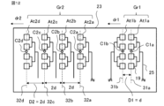
A plurality of antennas of the first antenna group Gr1 and the second antenna group Gr2 may be arranged in the extending direction of the phase center line. The seventh example of the antenna arrangement shown in FIG. 25 corresponds to the antenna arrangement including two sets of the first antenna group Gr1 and the second antenna group Gr2 of the first example of the antenna arrangement shown in FIG. The first antenna group Gr1 includes four transmitting antennas Tx1, Tx2, Tx3, and Tx4, and the second antenna group Gr2 includes eight receiving antennas Rx1, Rx2, Rx3, Rx4, Rx5, Rx6, Rx7, Equipped with Rx8. The transmitting antenna Tx includes a pair of antennas whose antenna spacing is less than or equal to the distance d, and the receiving antenna Rx does not include a pair of antennas whose antenna spacing is less than or equal to the distance d. The transmitting antennas Tx1 and Tx2 constitute a first antenna group 22a, and the transmitting antennas Tx3 and Tx4 constitute a first antenna group 22b. Receiving antennas Rx1 to Rx4 constitute a second antenna group 24a, and receiving antennas Rx5 to Rx8 constitute a second antenna group 24b. The first antenna group 22b and the second antenna group 24b are a first example of the antenna arrangement shown in FIG. The first antenna group 22a and the second antenna group 24a have an antenna arrangement in which the transmitting antenna Tx and the receiving antenna Rx in the first example of the antenna arrangement shown in FIG. 4 are shifted in the direction in which the phase center line extends.

なお、図25では、第一アンテナ群Gr1の第一配列方向dr1に配置された第一アンテナ組が1個であり、第二アンテナ群Gr2の第二配列方向dr2に配置された第アンテナ組が1個である例を示した。しかし、第一アンテナ群Gr1の第一配列方向dr1に配置された第一アンテナ組が2個以上であり、第二アンテナ群Gr2の第二配列方向dr2に配置された第アンテナ組が2個以上である場合もある。このような場合、第一アンテナ群Gr1は、第一配列方向dr1に配置された複数の第一アンテナAt1を有するA群と、A群と同一構成を有しており、第一配列方向dr1に垂直な方向である第四配列方向dr4に配置されたB群と、を備えているということもできる。図25の場合、A群は第一アンテナ組22aであり、B群は第一アンテナ組22bである。また、第二アンテナ群Gr2は、第二配列方向dr2に配置された複数の第二アンテナAt2を有するC群と、C群と同一構成を有しており、第二配列方向dr2に垂直な方向である第五配列方向dr5に配置されたD群と、を備えているということもできる。図25の場合、C群は第二アンテナ組24aであり、D群は第二アンテナ組24bである。 In addition, in FIG. 25, there is one first antenna group arranged in the first arrangement direction dr1 of the first antenna group Gr1, and one second antenna group arranged in the second arrangement direction dr2 of the second antenna group Gr2. An example is shown in which there is one. However, there are two or more first antenna sets arranged in the first arrangement direction dr1 of the first antenna group Gr1, and two or more second antenna sets arranged in the second arrangement direction dr2 of the second antenna group Gr2. In some cases, it is more than that. In such a case, the first antenna group Gr1 has the same configuration as the A group having a plurality of first antennas At1 arranged in the first arrangement direction dr1, and It can also be said to include a B group arranged in a fourth arrangement direction dr4, which is a perpendicular direction. In the case of FIG. 25, group A is the first antenna group 22a, and group B is the first antenna group 22b. Further, the second antenna group Gr2 has the same configuration as the C group having a plurality of second antennas At2 arranged in the second arrangement direction dr2, and is directed in a direction perpendicular to the second arrangement direction dr2. It can also be said that the D group is arranged in the fifth arrangement direction dr5. In the case of FIG. 25, group C is the second antenna group 24a, and group D is the second antenna group 24b.

図25に示したアンテナ配置の第七例のアンテナを備えたレーダ装置1は、送信回路12の送信切替スイッチ124が、送信アンテナTx1、Tx2、Tx3、Tx4を切替えるように構成されている。また、受信回路13は、受信アンテナRx1、Rx2、Rx3、Rx4、Rx5、Rx6、Rx7、Rx8に対応する、8個の混合器131、8個のフィルタ回路141、8個のアナログデジタル変換器151を備えた構成になっている。アンテナ配置の第七例のアンテナを備えたレーダ装置1は、Tx1、Tx2、Tx3、Tx4の順で繰り返す変調パターン61を有する送信信号を送信する。 The radar apparatus 1 equipped with the antenna of the seventh example of the antenna arrangement shown in FIG. 25 is configured such that the transmission changeover switch 124 of the transmission circuit 12 switches among the transmission antennas Tx1, Tx2, Tx3, and Tx4. The receiving circuit 13 also includes eight mixers 131, eight filter circuits 141, and eight analog-to-digital converters 151 corresponding to receiving antennas Rx1, Rx2, Rx3, Rx4, Rx5, Rx6, Rx7, and Rx8. It is configured with the following. The radar device 1 equipped with the antenna of the seventh example of antenna arrangement transmits a transmission signal having a modulation pattern 61 that repeats in the order of Tx1, Tx2, Tx3, and Tx4.

送信アンテナTx1、Tx3は位相中心線28aに沿って配置された複数の素子アンテナ19を備えており、送信アンテナTx2、Tx4は位相中心線28bに沿って配置された複数の素子アンテナ19を備えている。受信アンテナRx1、Rx5は位相中心線27aに沿って配置された複数の素子アンテナ19を備えており、受信アンテナRx2、Rx6は位相中心線27bに沿って配置された複数の素子アンテナ19を備えている。受信アンテナRx3、Rx7は位相中心線27cに沿って配置された複数の素子アンテナ19を備えており、受信アンテナRx4、Rx8は位相中心線27dに沿って配置された複数の素子アンテナ19を備えている。送信アンテナTx1、Tx3と送信アンテナTx2、Tx4とは、互いに平行になるようにすなわち位相中心線が平行になるように、基板23の表面に並んで配置されている。受信アンテナRx1、Rx5と、受信アンテナRx2、Rx6と、受信アンテナRx3、Rx7と、受信アンテナRx4、Rx8とは、互いに平行になるようにすなわち位相中心線が平行になるように、基板23の表面に並んで配置されている。 The transmitting antennas Tx1 and Tx3 include a plurality of element antennas 19 arranged along a phase center line 28a, and the transmitting antennas Tx2 and Tx4 include a plurality of element antennas 19 arranged along a phase center line 28b. There is. The receiving antennas Rx1 and Rx5 include a plurality of element antennas 19 arranged along a phase center line 27a, and the receiving antennas Rx2 and Rx6 include a plurality of element antennas 19 arranged along a phase center line 27b. There is. The receiving antennas Rx3 and Rx7 include a plurality of element antennas 19 arranged along a phase center line 27c, and the receiving antennas Rx4 and Rx8 include a plurality of element antennas 19 arranged along a phase center line 27d. There is. The transmitting antennas Tx1, Tx3 and the transmitting antennas Tx2, Tx4 are arranged side by side on the surface of the substrate 23 so that they are parallel to each other, that is, so that their phase center lines are parallel to each other. The receiving antennas Rx1 and Rx5, the receiving antennas Rx2 and Rx6, the receiving antennas Rx3 and Rx7, and the receiving antennas Rx4 and Rx8 are arranged on the surface of the substrate 23 so that they are parallel to each other, that is, so that their phase center lines are parallel to each other. are placed side by side.

第一アンテナ組22aにおける送信アンテナTx1、Tx2は第一配列方向dr1に配置され、第一アンテナ組22bにおける送信アンテナTx3、Tx4は第一配列方向dr1に配置されている。第二アンテナ組24aにおける受信アンテナRx1~Rx4は第二配列方向dr2に配置され、第二アンテナ組24bにおける受信アンテナRx5~Rx8は第二配列方向dr2に配置されている。図25では、第二アンテナ組24bにおける受信アンテナRx5~Rx8の各位相中心と第一アンテナ組22bにおける送信アンテナTx3、Tx4の各位相中心とが同一軸である破線29aに配置されている例を示した。第一アンテナ組22a、第一アンテナ組22bは、第一配列方向dr1に垂直な第四配列方向dr4の正側に向かって順に配置されている。第二アンテナ組24a、第二アンテナ組24bは、第二配列方向dr2に垂直な第五配列方向dr5の正側に向かって順に配置されている。第一アンテナ組22aにおける送信アンテナTx1、Tx2の位相中心は同一軸である破線29bに配置されている。第二アンテナ組24aの受信アンテナRx1~Rx4の位相中心は同一軸である破線29cに配置されている。破線29a、29b、29cは互いに平行である。 The transmitting antennas Tx1 and Tx2 in the first antenna group 22a are arranged in the first arrangement direction dr1, and the transmitting antennas Tx3 and Tx4 in the first antenna group 22b are arranged in the first arrangement direction dr1. The receiving antennas Rx1 to Rx4 in the second antenna group 24a are arranged in the second arrangement direction dr2, and the receiving antennas Rx5 to Rx8 in the second antenna group 24b are arranged in the second arrangement direction dr2. In FIG. 25, an example is shown in which the phase centers of the receiving antennas Rx5 to Rx8 in the second antenna group 24b and the phase centers of the transmitting antennas Tx3 and Tx4 in the first antenna group 22b are arranged on the same axis as the broken line 29a. Indicated. The first antenna group 22a and the first antenna group 22b are arranged in order toward the positive side of the fourth arrangement direction dr4 perpendicular to the first arrangement direction dr1. The second antenna group 24a and the second antenna group 24b are arranged in order toward the positive side of the fifth arrangement direction dr5 perpendicular to the second arrangement direction dr2. The phase centers of the transmitting antennas Tx1 and Tx2 in the first antenna group 22a are arranged on the same axis, which is a broken line 29b. The phase centers of the receiving antennas Rx1 to Rx4 of the second antenna group 24a are arranged on the same axis, which is a broken line 29c. Dashed lines 29a, 29b, and 29c are parallel to each other.

第一アンテナ組22aにおける送信アンテナTx1と送信アンテナTx2との間の送信アンテナ間隔Dtx、第一アンテナ組22bにおける送信アンテナTx3と送信アンテナTx4との間の送信アンテナ間隔Dtx、すなわち位相中心線28aと位相中心線28bとの間隔は、距離dと等しい間隔となっている。第二アンテナ組24aにおける受信アンテナRx1~Rx4の隣接する受信アンテナRx間の受信アンテナ間隔Drx、第二アンテナ組24bにおける受信アンテナRx5~Rx8の隣接する受信アンテナRx間の受信アンテナ間隔Drx、すなわち位相中心線27a~27dの隣接する位相中心線間の間隔は、距離dの2倍すなわち2dとなっている。第一アンテナ組22aと第一アンテナ組22bとの間の第一アンテナ組間隔である送信アンテナ組間隔Dtxsvは、破線29bと破線29aとの間隔である。第二アンテナ組24aと第二アンテナ組24bとの間の第二アンテナ組間隔である受信アンテナ組間隔Drxsvは、破線29cと破線29aとの間隔である。 The transmission antenna interval Dtx between the transmission antenna Tx1 and the transmission antenna Tx2 in the first antenna group 22a, the transmission antenna interval Dtx between the transmission antenna Tx3 and the transmission antenna Tx4 in the first antenna group 22b, that is, the phase center line 28a The distance from the phase center line 28b is equal to the distance d. The receiving antenna spacing Drx between adjacent receiving antennas Rx of receiving antennas Rx1 to Rx4 in the second antenna group 24a, the receiving antenna spacing Drx between adjacent receiving antennas Rx of receiving antennas Rx5 to Rx8 in the second antenna group 24b, that is, the phase The distance between adjacent phase center lines of the center lines 27a to 27d is twice the distance d, that is, 2d. The transmission antenna group interval Dtxsv, which is the first antenna group interval between the first antenna group 22a and the first antenna group 22b, is the interval between the broken line 29b and the broken line 29a. The receiving antenna group interval Drxsv, which is the second antenna group interval between the second antenna group 24a and the second antenna group 24b, is the interval between the broken line 29c and the broken line 29a.

図25のアンテナ配置の第七例における送信アンテナTx及び受信アンテナRxで形成される仮想受信アンテナ群50を図26に示した。仮想受信アンテナ群50は、4個の送信アンテナTx1~Tx4と8個の受信アンテナRx1~Rx8によって、32個の仮想受信アンテナVR1~VR32が形成される。白抜き実線円で示したVR1、VR2、VR3、VR4、VR5、VR6、VR7、VR8が送信アンテナTx1で送信して受信アンテナRx1~Rx8で受信した信号で形成される仮想受信アンテナであり、白抜き破線円で示したVR9、VR10、VR11、VR12、VR13、VR14、VR15、VR16が送信アンテナTx2で送信して受信アンテナRx1~Rx8で受信した信号で形成される仮想受信アンテナである。パターン有の実線円で示したVR17、VR18、VR19、VR20、VR21、VR22、VR23、VR24が送信アンテナTx3で送信して受信アンテナRx1~Rx8で受信した信号で形成される仮想受信アンテナであり、パターン有の破線円で示したVR25、VR26、VR27、VR28、VR29、VR30、VR31、VR32が送信アンテナTx4で送信して受信アンテナRx1~Rx8で受信した信号で形成される仮想受信アンテナである。 FIG. 26 shows a virtual reception antenna group 50 formed by the transmission antenna Tx and reception antenna Rx in the seventh example of the antenna arrangement shown in FIG. In the virtual receiving antenna group 50, 32 virtual receiving antennas VR1 to VR32 are formed by four transmitting antennas Tx1 to Tx4 and eight receiving antennas Rx1 to Rx8. VR1, VR2, VR3, VR4, VR5, VR6, VR7, and VR8 indicated by solid white circles are virtual receiving antennas formed by signals transmitted by transmitting antenna Tx1 and received by receiving antennas Rx1 to Rx8, and are shown in white. VR9, VR10, VR11, VR12, VR13, VR14, VR15, and VR16 indicated by broken-line circles are virtual receiving antennas formed by signals transmitted by the transmitting antenna Tx2 and received by the receiving antennas Rx1 to Rx8. VR17, VR18, VR19, VR20, VR21, VR22, VR23, and VR24 shown by solid circles with patterns are virtual receiving antennas formed by signals transmitted by the transmitting antenna Tx3 and received by the receiving antennas Rx1 to Rx8, VR25, VR26, VR27, VR28, VR29, VR30, VR31, and VR32 indicated by broken line circles with patterns are virtual receiving antennas formed by signals transmitted by the transmitting antenna Tx4 and received by the receiving antennas Rx1 to Rx8.

図26に示した仮想受信アンテナ群50は、第一配列方向dr1及び第二配列方向dr2に平行な第三配列方向dr3に配列された8個の仮想受信アンテナVRの組が第三配列方向dr3に垂直な第六配列方向dr6に4組配列されている。第六配列方向dr6は、第四配列方向dr4及び第五配列方向dr5に平行な方向である。第六配列方向dr6の正側に向かって順に第一組、第二組、第三組、第四組とする。第一組の仮想受信アンテナVR1、VR9、VR2、VR10、VR3、VR11、VR4、VR12における隣接する仮想受信アンテナ間隔Dvrが距離dで等間隔になるように構成される。仮想受信アンテナVR1~VR4は送信アンテナTx1で送信して受信アンテナRx1~Rx4で受信した信号で形成される第一組の仮想受信アンテナであり、仮想受信アンテナVR9~VR12は送信アンテナTx2で送信して受信アンテナRx1~Rx4で受信した信号で形成される第一組の仮想受信アンテナである。 The virtual receiving antenna group 50 shown in FIG. 26 includes a set of eight virtual receiving antennas VR arranged in a third arrangement direction dr3 parallel to the first arrangement direction dr1 and the second arrangement direction dr2. Four sets are arranged in a sixth arrangement direction dr6 perpendicular to . The sixth arrangement direction dr6 is a direction parallel to the fourth arrangement direction dr4 and the fifth arrangement direction dr5. A first set, a second set, a third set, and a fourth set are arranged in order toward the positive side of the sixth arrangement direction dr6. The virtual receiving antennas of the first set of virtual receiving antennas VR1, VR9, VR2, VR10, VR3, VR11, VR4, and VR12 are configured so that the distance Dvr between adjacent virtual receiving antennas is equal to the distance d. Virtual receiving antennas VR1 to VR4 are a first set of virtual receiving antennas formed by signals transmitted by transmitting antenna Tx1 and received by receiving antennas Rx1 to Rx4, and virtual receiving antennas VR9 to VR12 are formed by signals transmitted by transmitting antenna Tx2. This is a first set of virtual receiving antennas formed by signals received by the receiving antennas Rx1 to Rx4.

第二組の仮想受信アンテナVR5、VR13、VR6、VR14、VR7、VR15、VR8、VR16における隣接する仮想受信アンテナ間隔Dvrが距離dで等間隔になるように構成される。仮想受信アンテナVR5~VR8は送信アンテナTx1で送信して受信アンテナRx5~Rx8で受信した信号で形成される第二組の仮想受信アンテナであり、仮想受信アンテナVR13~VR16は送信アンテナTx2で送信して受信アンテナRx5~Rx8で受信した信号で形成される第二組の仮想受信アンテナである。第三組の仮想受信アンテナVR17、VR25、VR18、VR26、VR19、VR27、VR20、VR28における隣接する仮想受信アンテナ間隔Dvrが距離dで等間隔になるように構成される。仮想受信アンテナVR17~VR20は送信アンテナTx3で送信して受信アンテナRx1~Rx4で受信した信号で形成される第三組の仮想受信アンテナであり、仮想受信アンテナVR25~VR28は送信アンテナTx4で送信して受信アンテナRx1~Rx4で受信した信号で形成される第三組の仮想受信アンテナである。第四組の仮想受信アンテナVR21、VR29、VR22、VR30、VR23、VR31、VR24、VR32における隣接する仮想受信アンテナ間隔Dvrが距離dで等間隔になるように構成される。仮想受信アンテナVR21~VR24は送信アンテナTx3で送信して受信アンテナRx5~Rx8で受信した信号で形成される第四組の仮想受信アンテナであり、仮想受信アンテナVR29~VR32は送信アンテナTx4で送信して受信アンテナRx5~Rx8で受信した信号で形成される第四組の仮想受信アンテナである。 The second set of virtual receiving antennas VR5, VR13, VR6, VR14, VR7, VR15, VR8, and VR16 are configured so that the distance Dvr between adjacent virtual receiving antennas is equal to the distance d. Virtual receiving antennas VR5 to VR8 are a second set of virtual receiving antennas formed by signals transmitted by transmitting antenna Tx1 and received by receiving antennas Rx5 to Rx8, and virtual receiving antennas VR13 to VR16 are formed by signals transmitted by transmitting antenna Tx2. This is a second set of virtual receiving antennas formed by the signals received by the receiving antennas Rx5 to Rx8. The third set of virtual receiving antennas VR17, VR25, VR18, VR26, VR19, VR27, VR20, and VR28 are configured so that the distance Dvr between adjacent virtual receiving antennas is equal to the distance d. Virtual receiving antennas VR17 to VR20 are a third set of virtual receiving antennas formed by signals transmitted by transmitting antenna Tx3 and received by receiving antennas Rx1 to Rx4, and virtual receiving antennas VR25 to VR28 are formed by signals transmitted by transmitting antenna Tx4. This is a third set of virtual receiving antennas formed by the signals received by the receiving antennas Rx1 to Rx4. The fourth set of virtual receiving antennas VR21, VR29, VR22, VR30, VR23, VR31, VR24, and VR32 are configured such that the distance Dvr between adjacent virtual receiving antennas is equal to the distance d. Virtual receiving antennas VR21 to VR24 are a fourth set of virtual receiving antennas formed by signals transmitted by transmitting antenna Tx3 and received by receiving antennas Rx5 to Rx8, and virtual receiving antennas VR29 to VR32 are formed by signals transmitted by transmitting antenna Tx4. This is a fourth set of virtual receiving antennas formed by the signals received by the receiving antennas Rx5 to Rx8.

第一組の仮想受信アンテナと第二組の仮想受信アンテナとの第六配列方向dr6における間隔は受信アンテナ組間隔Drxsvであり、第三組の仮想受信アンテナと第四組の仮想受信アンテナとの第六配列方向dr6における間隔は受信アンテナ組間隔Drxsvである。第一組の仮想受信アンテナと第三組の仮想受信アンテナとの第六配列方向dr6における間隔は送信アンテナ組間隔Dtxsvである。アンテナ配置の第七例のアンテナを備えたレーダ装置1は、アンテナ配置の第一例のアンテナを2組備えた実施の形態1のレーダ装置1に相当するので、アンテナ配置の第一例のアンテナを備えた実施の形態1のレーダ装置1と同様の効果を奏する。また、アンテナ配置の第七例のアンテナを備えたレーダ装置1は、第三配列方向dr3とこれに垂直な第六配列方向dr6の2次元で対象物体33の距離、相対速度、及び、角度を測定することができる。 The interval between the first set of virtual receiving antennas and the second set of virtual receiving antennas in the sixth arrangement direction dr6 is the receiving antenna group interval Drxsv, and the interval between the third set of virtual receiving antennas and the fourth set of virtual receiving antennas is the receiving antenna group interval Drxsv. The spacing in the sixth arrangement direction dr6 is the receiving antenna group spacing Drxsv. The interval between the first set of virtual receiving antennas and the third set of virtual receiving antennas in the sixth arrangement direction dr6 is the transmitting antenna group interval Dtxsv. The radar device 1 equipped with the antenna of the seventh example of antenna arrangement corresponds to the radar device 1 of Embodiment 1 equipped with two sets of antennas of the first example of antenna arrangement, so the antenna of the first example of antenna arrangement The same effects as the radar device 1 of Embodiment 1 including the above are achieved. Moreover, the radar device 1 equipped with the antenna of the seventh example of antenna arrangement measures the distance, relative velocity, and angle of the target object 33 in two dimensions of the third arrangement direction dr3 and the sixth arrangement direction dr6 perpendicular to this. can be measured.

実施の形態1のレーダ装置1は、予め定められた距離dの間隔に物理的に3チャンネル以上の第一アンテナAt1が配置できないために、距離dの間隔に物理的に2チャンネルの第一アンテナAt1が配置された例である。しかし、実施の形態1のレーダ装置1は、第一アンテナAt1及び第二アンテナAt2の送受信により形成される複数の仮想受信アンテナVRが距離dの等間隔で配置できるので、サイドローブを低減し誤検出を抑制することができる。 Since the radar device 1 of the first embodiment cannot physically arrange the first antennas At1 of three or more channels at intervals of a predetermined distance d, the first antennas of two channels physically cannot be arranged at intervals of a predetermined distance d. This is an example in which At1 is arranged. However, in the radar device 1 of the first embodiment, since the plurality of virtual reception antennas VR formed by the transmission and reception of the first antenna At1 and the second antenna At2 can be arranged at equal intervals with a distance d, side lobes can be reduced and errors can be made. Detection can be suppressed.

以上のように、実施の形態1のレーダ装置1は、送信信号を対象物体33に向けて放射する複数の送信アンテナTxと、送信信号が対象物体33にて反射された反射信号を受信して受信信号として出力する複数の受信アンテナRxと、複数の受信アンテナRxのそれぞれから出力された受信信号を処理する処理部11と、を備えている。当該レーダ装置1に要求される視野範囲に基づいて決定される、隣接するアンテナ間のアンテナ間隔を基本距離(距離d)とし、複数の送信アンテナTxか複数の受信アンテナRxのいずれかを備えたアンテナ群であり、隣接するアンテナ間のアンテナ間隔D1が基本距離(距離d)である複数の第一アンテナAt1を有する第一アンテナ組を備えたアンテナ群を第一アンテナ群Gr1とし、第一アンテナ群Gr1の第一アンテナAt1と異なる他方の複数のアンテナを備えたアンテナ群であり、隣接するアンテナ間のアンテナ間隔D2が基本距離(距離d)の2倍である複数の第二アンテナAt2を有する第二アンテナ組を備えたアンテナ群を第二アンテナ群Gr2とする。第一アンテナAt1及び第二アンテナAt2は、複数の素子アンテナ19と素子アンテナ19に電力を給電する給電回路25とを備えている。複数の第一アンテナAt1は、送信信号の送信方向に垂直な第一配列方向dr1に並べて配置されており、それぞれの給電回路25を第一配列方向dr1の正側又は負側に有している。複数の第二アンテナAt2は、送信信号の送信方向に垂直で第一配列方向dr1に平行な第二配列方向dr2に並べて配置されており、給電回路25を第二配列方向dr2の正側又は負側に有している。第一アンテナ組における隣接するアンテナ間に給電回路25が配置されていない。第一アンテナ群Gr1の複数の第一アンテナAt1及び第二アンテナ群Gr2の複数の第二アンテナAt2によって形成される複数の仮想受信アンテナVRから構成される仮想受信アンテナ群50は、送信信号の送信方向に垂直で第一配列方向dr1及び第二配列方向dr2に平行な第三配列方向dr3に並べて配置されており、第三配列方向dr3における隣接する仮想受信アンテナVRの間隔(仮想受信アンテナ間隔Dvr)が基本距離(距離d)である。実施の形態1のレーダ装置1は、この構成により、第一アンテナ群Gr1が隣接するアンテナ間のアンテナ間隔D1が基本距離(距離d)である複数の第一アンテナAt1を有する第一アンテナ組を備え、第二アンテナ群Gr2が隣接するアンテナ間のアンテナ間隔D2が基本距離(距離d)の2倍である複数の第二アンテナAt2を有する第二アンテナ組を備え、複数の第一アンテナAt1及び複数の第二アンテナAt2の送受信により形成される複数の仮想受信アンテナVRの隣接する仮想受信アンテナVRの間隔(仮想受信アンテナ間隔Dvr)が基本距離(距離d)であるので、予め定められた距離dの間隔に物理的に3チャンネル以上の受信アンテナRx又は送信アンテナTxである第一アンテナAt1を並べられない場合でも、サイドローブを低減し誤検出を抑制することができる。 As described above, the radar device 1 according to the first embodiment includes a plurality of transmitting antennas Tx that radiate a transmitted signal toward the target object 33, and a plurality of transmitting antennas Tx that receive a reflected signal obtained by reflecting the transmitted signal from the target object 33. It includes a plurality of reception antennas Rx that output as reception signals, and a processing section 11 that processes the reception signals output from each of the plurality of reception antennas Rx. The radar device 1 is provided with either a plurality of transmitting antennas Tx or a plurality of receiving antennas Rx, with the antenna interval between adjacent antennas determined based on the field of view required for the radar device 1 as a basic distance (distance d). An antenna group that is an antenna group and includes a first antenna group having a plurality of first antennas At1 in which the antenna spacing D1 between adjacent antennas is a basic distance (distance d) is referred to as a first antenna group Gr1; The antenna group includes a plurality of antennas different from the first antenna At1 of the group Gr1, and includes a plurality of second antennas At2 in which the antenna spacing D2 between adjacent antennas is twice the basic distance (distance d). The antenna group including the second antenna group is referred to as a second antenna group Gr2. The first antenna At1 and the second antenna At2 include a plurality of element antennas 19 and a power feeding circuit 25 that feeds power to the element antennas 19. The plurality of first antennas At1 are arranged in a first arrangement direction dr1 perpendicular to the transmission direction of the transmission signal, and have respective feeding circuits 25 on the positive side or the negative side of the first arrangement direction dr1. . The plurality of second antennas At2 are arranged in a second arrangement direction dr2 that is perpendicular to the transmission direction of the transmission signal and parallel to the first arrangement direction dr1, and the feeding circuit 25 is arranged on the positive side or the negative side of the second arrangement direction dr2. Have it on the side. The feeding circuit 25 is not arranged between adjacent antennas in the first antenna group. A virtual reception antenna group 50 configured of a plurality of virtual reception antennas VR formed by a plurality of first antennas At1 of the first antenna group Gr1 and a plurality of second antennas At2 of the second antenna group Gr2 transmits transmission signals. They are arranged in a third arrangement direction dr3 that is perpendicular to the direction and parallel to the first arrangement direction dr1 and the second arrangement direction dr2. ) is the basic distance (distance d). With this configuration, the radar device 1 of the first embodiment includes a first antenna group Gr1 having a plurality of first antennas At1 in which the antenna spacing D1 between adjacent antennas is a basic distance (distance d). The second antenna group Gr2 includes a second antenna group having a plurality of second antennas At2 in which the antenna interval D2 between adjacent antennas is twice the basic distance (distance d), Since the interval (virtual reception antenna interval Dvr) between adjacent virtual reception antennas VR of the plurality of virtual reception antennas VR formed by transmission and reception of the plurality of second antennas At2 is the basic distance (distance d), the predetermined distance is Even if the first antennas At1, which are the receiving antennas Rx or transmitting antennas Tx of three or more channels, cannot be physically arranged at intervals of d, side lobes can be reduced and false detections can be suppressed.

実施の形態2.
図27は実施の形態2に係るレーダ装置のアンテナ配置を示す図であり、図28は図27のアンテナ配置に対応した仮想受信アンテナ群を示す図である。実施の形態1のレーダ装置1では、第一アンテナ群Gr1が第一配列方向dr1に2個で1組のアンテナ組を1個のみ備える例を説明した。実施の形態2のレーダ装置1は、第一アンテナ群Gr1が第一配列方向dr1に2個で1組のアンテナ組を複数備える例である。実施の形態1のレーダ装置1と異なる部分を主に説明する。図27のアンテナ配置のアンテナを備えた実施の形態2のレーダ装置1は、2個の送信アンテナTx1、Tx2、4個の受信アンテナRx1、Rx2、Rx3、RX4、図1に示した送信回路12、受信回路13、処理部11を備えている。図27のアンテナ配置のアンテナを備えたレーダ装置1は、Tx1、Tx2の順で繰り返す変調パターン61を有する送信信号を送信する。
Embodiment 2.
FIG. 27 is a diagram showing the antenna arrangement of the radar device according to the second embodiment, and FIG. 28 is a diagram showing a virtual reception antenna group corresponding to the antenna arrangement of FIG. 27. In the radar device 1 of the first embodiment, an example has been described in which the first antenna group Gr1 includes only one antenna set of two antennas in the first arrangement direction dr1. The radar device 1 of the second embodiment is an example in which the first antenna group Gr1 includes a plurality of two antenna groups in the first arrangement direction dr1. The parts that are different from the radar device 1 of Embodiment 1 will be mainly explained. The radar device 1 of the second embodiment equipped with the antenna arrangement shown in FIG. , a receiving circuit 13, and a processing section 11. The radar device 1 equipped with an antenna having the antenna arrangement shown in FIG. 27 transmits a transmission signal having a modulation pattern 61 that repeats in the order of Tx1 and Tx2.

送信アンテナTx、受信アンテナRxについて説明する。図27に示したアンテナ配置では、受信アンテナRxが第一アンテナ群Gr1のアンテナすなわち第一アンテナAt1であり、送信アンテナTxが第二アンテナ群Gr2のアンテナすなわち第二アンテナAt2である。受信アンテナRx1、Rx2、RX3、RX4は第一配列方向dr1の正側に向かって順に配置されており、送信アンテナTx1、Tx2は第二配列方向dr2の正側に向かって順に配置されている。受信アンテナRx1、Rx2は、受信アンテナ間隔Drxすなわち位相中心線27aと位相中心線27bとの間隔が距離dと等しい間隔となっている。同様に、受信アンテナRx3、Rx4は、受信アンテナ間隔Drxすなわち位相中心線27cと位相中心線27dとの間隔が距離dと等しい間隔となっている。受信アンテナ間隔Drxは、第一アンテナAt1における距離dのアンテナ間隔D1(図12参照)である。受信アンテナRx1、Rx2は第一アンテナ組22aを構成し、受信アンテナRx3、Rx4は第一アンテナ組22bを構成している。第一アンテナ組22aと第一アンテナ組22bとの第一アンテナ組間隔Dg1sすなわち位相中心線27aと位相中心線27cとの間隔が距離dの4倍すなわち4dとなっている。なお、第一アンテナ組間隔Dg1sは、位相中心線27bと位相中心線27dとの間隔であってもよい。第一アンテナ組間隔Dg1sは、隣接する第一アンテナ組間の間隔である。 The transmitting antenna Tx and receiving antenna Rx will be explained. In the antenna arrangement shown in FIG. 27, the receiving antenna Rx is the antenna of the first antenna group Gr1, that is, the first antenna At1, and the transmitting antenna Tx is the antenna of the second antenna group Gr2, that is, the second antenna At2. The receiving antennas Rx1, Rx2, RX3, and RX4 are arranged in order toward the positive side in the first arrangement direction dr1, and the transmitting antennas Tx1 and Tx2 are arranged in order toward the positive side in the second arrangement direction dr2. The receiving antennas Rx1 and Rx2 have a receiving antenna spacing Drx, that is, the spacing between the phase center line 27a and the phase center line 27b, which is equal to the distance d. Similarly, the receiving antennas Rx3 and Rx4 have a receiving antenna spacing Drx, that is, the spacing between the phase center line 27c and the phase center line 27d, which is equal to the distance d. The reception antenna spacing Drx is the antenna spacing D1 (see FIG. 12) at the distance d in the first antenna At1. Receiving antennas Rx1 and Rx2 constitute a first antenna group 22a, and receiving antennas Rx3 and Rx4 constitute a first antenna group 22b. The first antenna group distance Dg1s between the first antenna group 22a and the first antenna group 22b, that is, the distance between the phase center line 27a and the phase center line 27c is four times the distance d, that is, 4d. Note that the first antenna group interval Dg1s may be the interval between the phase center line 27b and the phase center line 27d. The first antenna group interval Dg1s is the interval between adjacent first antenna groups.

送信アンテナTx1、Tx2は、送信アンテナ間隔Dtxすなわち位相中心線28aと位相中心線28bとの間隔が距離dの2倍すなわち2dとなっている。送信アンテナ間隔Dtxは、第二アンテナAt2における距離dの2倍のアンテナ間隔D2(図12参照)である。送信アンテナTx、受信アンテナRxの給電回路25は、各素子アンテナ19への配線長が等しくなるように形成される並列給電方式の給電回路を示した。送信アンテナTxは第二アンテナ群Gr2の第二アンテナAt2なので、他の信アンテナと隣接する領域に給電回路25が配置されており、素子アンテナ19が対向しないように配置されている例を示した。受信アンテナRxは第一アンテナ群Gr1の第一アンテナAt1なので、第一アンテナ組22aの受信アンテナRx1、Rx2は、他の受信アンテナと隣接する領域に給電回路25が配置されないように、素子アンテナ19が対向するように配置されている。同様に、第一アンテナ組22bの受信アンテナRx3、Rx4は、他の受信アンテナと隣接する領域に給電回路25が配置されないように、素子アンテナ19が対向するように配置されている。 In the transmitting antennas Tx1 and Tx2, the transmitting antenna spacing Dtx, that is, the spacing between the phase center line 28a and the phase center line 28b is twice the distance d, that is, 2d. The transmission antenna spacing Dtx is an antenna spacing D2 (see FIG. 12) that is twice the distance d at the second antenna At2. The feeding circuit 25 for the transmitting antenna Tx and the receiving antenna Rx is a parallel feeding circuit in which the wiring lengths to each element antenna 19 are equal. Since the transmitting antenna Tx is the second antenna At2 of the second antenna group Gr2, an example is shown in which the feeding circuit 25 is arranged in an area adjacent to other transmitting antennas, and the element antenna 19 is arranged so as not to face each other. Ta. Since the receiving antenna Rx is the first antenna At1 of the first antenna group Gr1, the receiving antennas Rx1 and Rx2 of the first antenna group 22a are connected to the element antenna 19 so that the feeding circuit 25 is not arranged in an area adjacent to other receiving antennas. are arranged to face each other. Similarly, the receiving antennas Rx3 and Rx4 of the first antenna group 22b are arranged so that the element antennas 19 face each other so that the feeding circuit 25 is not arranged in a region adjacent to other receiving antennas.

図27のアンテナ配置における送信アンテナTx及び受信アンテナRxで形成される仮想受信アンテナ群50を図28に示した。仮想受信アンテナ群50は、複数の仮想受信アンテナを備えている。2個の第二アンテナAt2である送信アンテナTx1、Tx2と、4個の第一アンテナAt1である受信アンテナRx1、Rx2、Rx3、Rx4により、8個の仮想受信アンテナVR1、VR2、VR3、VR4、VR5、VR6、VR7、VR8が形成される。8個の仮想受信アンテナVRにおける隣接する仮想受信アンテナVR間の間隔である仮想受信アンテナ間隔Dvrが距離dで等間隔になるように構成される。仮想受信アンテナ群50の各仮想受信アンテナVRは、等間隔の距離dで、第三配列方向dr3に配列されている。第三配列方向dr3は第一配列方向dr1及び第二配列方向dr2に平行な方向である。 FIG. 28 shows a virtual reception antenna group 50 formed by the transmission antenna Tx and reception antenna Rx in the antenna arrangement of FIG. 27. The virtual reception antenna group 50 includes a plurality of virtual reception antennas. Eight virtual reception antennas VR1, VR2, VR3, VR4, VR5, VR6, VR7, and VR8 are formed. The virtual receiving antenna spacing Dvr, which is the spacing between adjacent virtual receiving antennas VR among the eight virtual receiving antennas VR, is configured to be equally spaced at a distance d. The virtual receiving antennas VR of the virtual receiving antenna group 50 are arranged at equal distances d in the third arrangement direction dr3. The third arrangement direction dr3 is a direction parallel to the first arrangement direction dr1 and the second arrangement direction dr2.

図28の例では、仮想受信アンテナVR1~VR8が、それぞれ第三配列方向dr3の正側に向かって、VR1、VR2、VR5、VR6、VR3、VR4、VR7、VR8の順で配置されている。これらの仮想受信アンテナ群50のうち、実線円で示したVR1、VR2、VR3、VR4が送信アンテナTx1で送信して受信アンテナRx1~Rx4で受信した信号で形成される仮想受信アンテナであり、破線円で示したVR5、VR6、VR7、VR8が送信アンテナTx2で送信して受信アンテナRx1~Rx4で受信した信号で形成される仮想受信アンテナである。仮想受信アンテナVR1、VR2は第一アンテナ組22aの受信アンテナRx1、Rx2で受信した信号で形成される仮想受信アンテナであり、仮想受信アンテナVR3、VR4は第一アンテナ組22bの受信アンテナRx3、Rx4で受信した信号で形成される仮想受信アンテナである。このため、第一アンテナ組22aの受信アンテナRx1による仮想受信アンテナVR1と、第一アンテナ組22bの受信アンテナRx3による仮想受信アンテナVR3との間隔は、4dである第一アンテナ組間隔Dg1sとなっている。仮想受信アンテナVR1、VR3は第一アンテナ組22a、22bにおける第三配列方向dr3の負側の受信アンテナRx1、Rx3による仮想受信アンテナである。第一アンテナ組22a、22bにおける第三配列方向dr3の正側の受信アンテナRx2、Rx4による仮想受信アンテナVR2、VR4についても、互いの間隔は4dである第一アンテナ組間隔Dg1sとなっている。 In the example of FIG. 28, virtual receiving antennas VR1 to VR8 are arranged in the order of VR1, VR2, VR5, VR6, VR3, VR4, VR7, and VR8 toward the positive side in the third arrangement direction dr3. Among these virtual receiving antenna groups 50, VR1, VR2, VR3, and VR4 indicated by solid line circles are virtual receiving antennas formed by signals transmitted by transmitting antenna Tx1 and received by receiving antennas Rx1 to Rx4, and indicated by broken lines VR5, VR6, VR7, and VR8 indicated by circles are virtual receiving antennas formed by signals transmitted by the transmitting antenna Tx2 and received by the receiving antennas Rx1 to Rx4. Virtual reception antennas VR1 and VR2 are virtual reception antennas formed by signals received by reception antennas Rx1 and Rx2 of the first antenna group 22a, and virtual reception antennas VR3 and VR4 are formed by reception antennas Rx3 and Rx4 of the first antenna group 22b. This is a virtual receiving antenna formed by the signals received by the antenna. Therefore, the interval between the virtual reception antenna VR1 formed by the reception antenna Rx1 of the first antenna group 22a and the virtual reception antenna VR3 formed by the reception antenna Rx3 of the first antenna group 22b is the first antenna group interval Dg1s, which is 4d. There is. Virtual receiving antennas VR1 and VR3 are virtual receiving antennas formed by receiving antennas Rx1 and Rx3 on the negative side in the third arrangement direction dr3 in the first antenna sets 22a and 22b. The virtual reception antennas VR2 and VR4 formed by the reception antennas Rx2 and Rx4 on the positive side in the third arrangement direction dr3 in the first antenna groups 22a and 22b are also spaced apart from each other at a first antenna group interval Dg1s of 4d.

破線円で示したVR5、VR6、VR7、VR8も実線円で示したVR1、VR2、VR3、VR4と同様に、第一アンテナ組22aの受信アンテナRx1による仮想受信アンテナVR5と、第一アンテナ組22bの受信アンテナRx3による仮想受信アンテナVR7との間隔は、4dである第一アンテナ組間隔Dg1sとなっている。つまり、第一アンテナ組22a、22bにおける第三配列方向dr3の負側の受信アンテナRx1、Rx3による仮想受信アンテナVR5、VR7は互いの間隔は4dである第一アンテナ組間隔Dg1sとなっている。第一アンテナ組22a、22bにおける第三配列方向dr3の正側の受信アンテナRx2、Rx4による仮想受信アンテナVR6、VR8についても、互いの間隔は4dである第一アンテナ組間隔Dg1sとなっている。 Similarly to VR1, VR2, VR3, and VR4 indicated by solid line circles, VR5, VR6, VR7, and VR8 indicated by broken line circles are also virtual receiving antenna VR5 based on receiving antenna Rx1 of first antenna group 22a, and first antenna group 22b. The distance between the receiving antenna Rx3 and the virtual receiving antenna VR7 is the first antenna group distance Dg1s, which is 4d. In other words, the virtual receiving antennas VR5 and VR7 formed by the receiving antennas Rx1 and Rx3 on the negative side in the third arrangement direction dr3 in the first antenna groups 22a and 22b are spaced apart from each other by the first antenna group spacing Dg1s, which is 4d. The virtual reception antennas VR6 and VR8 formed by the reception antennas Rx2 and Rx4 on the positive side in the third arrangement direction dr3 in the first antenna groups 22a and 22b are also spaced apart from each other by the first antenna group spacing Dg1s, which is 4d.

第一アンテナ群Gr1における距離dの受信アンテナ間隔Drxすなわちアンテナ間隔D1で配置された2個の受信アンテナRxを有する第一アンテナ組22a、22b間の第一アンテナ組間隔Dg1sを、式(3)に従って決定する。
Dg1s=Ng2×D2 ・・・(3)
ここで、Ng2は第二アンテナの数すなわち第二アンテナ数である。図27のアンテナ配置の場合は、第二アンテナ数Ng2が2であり、第二アンテナ群Gr2の第二アンテナAt2が送信アンテナTxであり、第二アンテナ群Gr2の隣接する第二アンテナAt2間のアンテナ間隔D2が距離dの2倍の送信アンテナ間隔Dtxである。
The receiving antenna spacing Drx of the distance d in the first antenna group Gr1, that is, the first antenna group spacing Dg1s between the first antenna groups 22a and 22b having two receiving antennas Rx arranged at the antenna spacing D1 is expressed by equation (3). Decide accordingly.
Dg1s=Ng2×D2...(3)
Here, Ng2 is the number of second antennas, that is, the number of second antennas. In the case of the antenna arrangement in FIG. 27, the number of second antennas Ng2 is 2, the second antenna At2 of the second antenna group Gr2 is the transmitting antenna Tx, and the distance between the adjacent second antennas At2 of the second antenna group Gr2 is The antenna spacing D2 is the transmitting antenna spacing Dtx, which is twice the distance d.

図27のアンテナ配置の場合は、第一アンテナ組間隔Dg1sは2×D2であり、4dになる。前述したように、予め定められた距離dのアンテナ間隔D1で配置された複数の第一アンテナAt1は送信アンテナTxでも受信アンテナRxでもよい。第二アンテナAt2は第一アンテナAt1と逆動作のアンテナである。図27のアンテナ配置では、第一アンテナAt1が4個で、第二アンテナAt2が2個の例であった。しかし、実施の形態2のレーダ装置1におけるアンテナはこれに限定されない。第一アンテナAt1が4個以上の偶数で、第一アンテナ組を2個以上備え、第二アンテナAt2が2個以上あればよい。 In the case of the antenna arrangement shown in FIG. 27, the first antenna group interval Dg1s is 2×D2, which is 4d. As described above, the plurality of first antennas At1 arranged at antenna intervals D1 of a predetermined distance d may be either the transmitting antenna Tx or the receiving antenna Rx. The second antenna At2 is an antenna that operates in the opposite manner to the first antenna At1. In the antenna arrangement of FIG. 27, there are four first antennas At1 and two second antennas At2. However, the antenna in the radar device 1 of the second embodiment is not limited to this. It is sufficient that the number of first antennas At1 is an even number of four or more, the number of first antenna groups is two or more, and the number of second antennas At2 is two or more.

実施の形態2のレーダ装置1は、第一アンテナ群Gr1に含まれる第一アンテナAt1の数が4以上の偶数であり、第二アンテナ群Gr2に含まれる第二アンテナAt2の数が2以上であり、送信回路12、受信回路13が、第一アンテナAt1及び第二アンテナAt2の一方である送信アンテナTxの数、第一アンテナAt1及び第二アンテナAt2の他方である受信アンテナRxの数に対応した構成になっている。実施の形態2のレーダ装置1は、予め定められた距離dの間隔で配置された2個の第一アンテナAt1を有する第一アンテナ組における隣接する間隔である第一アンテナ組間隔Dg1sが、第二アンテナAt2の数である第二アンテナ数Ng2と第二アンテナ群Gr2における隣接する第二アンテナAt2間の間隔であるアンテナ間隔D2とを乗算した値になるように、第一アンテナAt1が配置されている。実施の形態2のレーダ装置1は、予め定められた距離dの間隔に物理的に3チャンネル以上の第一アンテナAt1が配置できない場合であるが、第一アンテナAt1及び第二アンテナAt2の送受信により形成される複数の仮想受信アンテナVRが距離dの等間隔で配置できるので、サイドローブを低減し誤検出を抑制することができる。 In the radar device 1 of the second embodiment, the number of first antennas At1 included in the first antenna group Gr1 is an even number of 4 or more, and the number of second antennas At2 included in the second antenna group Gr2 is 2 or more. Yes, the transmitting circuit 12 and the receiving circuit 13 correspond to the number of transmitting antennas Tx, which is one of the first antenna At1 and the second antenna At2, and the number of receiving antennas Rx, which is the other of the first antenna At1 and the second antenna At2. The structure is as follows. In the radar device 1 of the second embodiment, the first antenna group interval Dg1s, which is the adjacent interval in the first antenna group having two first antennas At1 arranged at a predetermined distance d, is The first antenna At1 is arranged so that the value is the product of the number of second antennas Ng2, which is the number of two antennas At2, and the antenna spacing D2, which is the spacing between adjacent second antennas At2 in the second antenna group Gr2. ing. In the radar device 1 of the second embodiment, although the first antenna At1 of three or more channels cannot be physically arranged at intervals of a predetermined distance d, the transmission and reception of the first antenna At1 and the second antenna At2 Since the formed plurality of virtual receiving antennas VR can be arranged at equal intervals of distance d, side lobes can be reduced and false detection can be suppressed.

アンテナ配置の第一例~第六例で配置された第一アンテナAt1及び第二アンテナAt2を備えた実施の形態1のレーダ装置1は、第一アンテナAt1が2チャンネルの場合に好適であった。これに対して、実施の形態2のレーダ装置1は、第一アンテナAt1が2チャンネル以上の偶数の場合に好適である。なお、実施の形態2のレーダ装置1は、図25に示したアンテナ配置の第七例と同様に、第一アンテナ群Gr1、第二アンテナ群Gr2のアンテナが位相中心線の延伸方向に複数組配置されていてもよい。この場合、第三配列方向dr3とこれに垂直な第六配列方向dr6の2次元で対象物体33の距離、相対速度、及び、角度を測定することができる。 The radar device 1 of Embodiment 1 including the first antenna At1 and the second antenna At2 arranged in the first to sixth examples of antenna arrangement was suitable when the first antenna At1 had two channels. . On the other hand, the radar device 1 of the second embodiment is suitable when the first antenna At1 has an even number of channels of two or more. Note that in the radar device 1 of the second embodiment, as in the seventh example of the antenna arrangement shown in FIG. may be placed. In this case, the distance, relative velocity, and angle of the target object 33 can be measured two-dimensionally in the third arrangement direction dr3 and the sixth arrangement direction dr6 perpendicular thereto.

実施の形態3.
図29は実施の形態3に係るレーダ装置のアンテナ配置を示す図であり、図30は図29の送信アンテナの配置を示す図である。図31は、図29のアンテナ配置に対応した仮想受信アンテナ群を示す図である。実施の形態2のレーダ装置1では、第一アンテナ群Gr1が第一配列方向dr1に2個で1組のアンテナ組を複数備える例を説明した。実施の形態3のレーダ装置1は、実施の形態2のレーダ装置1と同様に、第一アンテナ群Gr1が第一配列方向dr1に2個で1組のアンテナ組を複数備える例であるが、第二アンテナ群Gr2の第二アンテナAt2の数が2以上の素数である例である。実施の形態2のレーダ装置1と異なる部分を主に説明する。図29、図30のアンテナ配置のアンテナを備えた実施の形態3のレーダ装置1は、第一アンテナ群Gr1のアンテナ組が3組であり、第二アンテナ群Gr2の第二アンテナAt2である送信アンテナTxの数が3である点で、図27のアンテナ配置のアンテナを備えた実施の形態2のレーダ装置1と異なる。具体的には、図29、図30のアンテナ配置のアンテナを備えた実施の形態3のレーダ装置1は、3個の送信アンテナTx1、Tx2、Tx3、6個の受信アンテナRx1、Rx2、Rx3、Rx4、Rx5、Rx6、送信回路12、受信回路13、処理部11を備えている。送信回路12は、送信切替スイッチ124が3個の送信アンテナTx1、Tx2、Tx3を切替える構成になっている。受信回路13は、6個の受信アンテナRx1~Rx6に対応した構成になっている。図29、図30のアンテナ配置のアンテナを備えたレーダ装置1は、Tx1、Tx2、Tx3の順で繰り返す変調パターン61を有する送信信号を送信する。
Embodiment 3.
FIG. 29 is a diagram showing the antenna arrangement of the radar device according to the third embodiment, and FIG. 30 is a diagram showing the arrangement of the transmitting antenna of FIG. 29. FIG. 31 is a diagram showing a virtual reception antenna group corresponding to the antenna arrangement of FIG. 29. In the radar device 1 of the second embodiment, an example has been described in which the first antenna group Gr1 includes a plurality of two antenna groups in the first arrangement direction dr1. Similarly to the radar device 1 of Embodiment 2, the radar device 1 of the third embodiment is an example in which the first antenna group Gr1 includes a plurality of two antenna groups in the first arrangement direction dr1. This is an example in which the number of second antennas At2 of the second antenna group Gr2 is a prime number of 2 or more. The parts that are different from the radar device 1 of the second embodiment will be mainly explained. The radar apparatus 1 of the third embodiment including antennas having the antenna arrangement shown in FIGS. 29 and 30 has three antenna sets in the first antenna group Gr1, and a second antenna At2 in the second antenna group Gr2. This embodiment differs from the radar device 1 of the second embodiment, which includes antennas having the antenna arrangement shown in FIG. 27, in that the number of antennas Tx is three. Specifically, the radar device 1 according to the third embodiment including the antenna arrangement shown in FIGS. 29 and 30 includes three transmitting antennas Tx1, Tx2, Tx3, six receiving antennas Rx1, Rx2, Rx3, It includes Rx4, Rx5, Rx6, a transmitting circuit 12, a receiving circuit 13, and a processing section 11. The transmitting circuit 12 has a configuration in which a transmitting changeover switch 124 switches between three transmitting antennas Tx1, Tx2, and Tx3. The receiving circuit 13 has a configuration corresponding to six receiving antennas Rx1 to Rx6. The radar device 1 equipped with an antenna having the antenna arrangement shown in FIGS. 29 and 30 transmits a transmission signal having a modulation pattern 61 that repeats in the order of Tx1, Tx2, and Tx3.

送信アンテナTx、受信アンテナRxについて説明する。図29、図30に示したアンテナ配置では、受信アンテナRxが第一アンテナ群Gr1のアンテナすなわち第一アンテナAt1であり、送信アンテナTxが第二アンテナ群Gr2のアンテナすなわち第二アンテナAt2である。受信アンテナRx1~Rx6は第一配列方向dr1の正側に向かって順に配置されており、送信アンテナTx1、Tx2、Tx3は第二配列方向dr2の正側に向かって順に配置されている。受信アンテナRx1、Rx2は第一アンテナ組22aを構成し、受信アンテナRx3、Rx4は第一アンテナ組22bを構成し、受信アンテナRx5、Rx6は第一アンテナ組22cを構成している。第一アンテナ組22a、22bは実施の形態2で説明した通りである。第一アンテナ組22cの受信アンテナRx5、Rx6は、受信アンテナ間隔Drxすなわち位相中心線27eと位相中心線27fとの間隔が距離dと等しい間隔となっている。受信アンテナ間隔Drxは、第一アンテナAt1における距離dのアンテナ間隔D1(図12参照)である。第一アンテナ組22a、22b、22cの隣接する第一アンテナ組間の間隔すなわち第一アンテナ組間隔Dg1sは、距離dの6倍すなわち6dとなっている。第一アンテナ組22aと第一アンテナ組22bとの間隔は位相中心線27aと位相中心線27cとの間隔又は位相中心線27bと位相中心線27dとの間隔であり、第一アンテナ組22bと第一アンテナ組22cとの間隔は位相中心線27cと位相中心線27eとの間隔又は位相中心線27dと位相中心線27fとの間隔である。 The transmitting antenna Tx and receiving antenna Rx will be explained. In the antenna arrangement shown in FIGS. 29 and 30, the receiving antenna Rx is the antenna of the first antenna group Gr1, that is, the first antenna At1, and the transmitting antenna Tx is the antenna of the second antenna group Gr2, that is, the second antenna At2. The receiving antennas Rx1 to Rx6 are arranged in order toward the positive side in the first arrangement direction dr1, and the transmitting antennas Tx1, Tx2, and Tx3 are arranged in order toward the positive side in the second arrangement direction dr2. Receiving antennas Rx1 and Rx2 constitute a first antenna group 22a, receiving antennas Rx3 and Rx4 constitute a first antenna group 22b, and receiving antennas Rx5 and Rx6 constitute a first antenna group 22c. The first antenna set 22a, 22b is as described in the second embodiment. The receiving antennas Rx5 and Rx6 of the first antenna group 22c are arranged such that the receiving antenna spacing Drx, that is, the spacing between the phase center line 27e and the phase center line 27f is equal to the distance d. The reception antenna spacing Drx is the antenna spacing D1 (see FIG. 12) at the distance d in the first antenna At1. The interval between adjacent first antenna sets 22a, 22b, and 22c, that is, the first antenna group interval Dg1s, is six times the distance d, or 6d. The distance between the first antenna group 22a and the first antenna group 22b is the distance between the phase center line 27a and the phase center line 27c or the distance between the phase center line 27b and the phase center line 27d. The distance from one antenna group 22c is the distance between the phase center line 27c and the phase center line 27e or the distance between the phase center line 27d and the phase center line 27f.

送信アンテナTx1、Tx2、Tx3は、隣接する送信アンテナTx間の間隔すなわち送信アンテナ間隔Dtxは距離dの2倍すなわち2dとなっている。送信アンテナTx1と送信アンテナTx2との間隔は位相中心線28aと位相中心線28bとの間隔であり、送信アンテナTx2と送信アンテナTx3との間隔は位相中心線28bと位相中心線28cとの間隔である。送信アンテナ間隔Dtxは、第二アンテナAt2における距離dの2倍のアンテナ間隔D2(図12参照)である。送信アンテナTx、受信アンテナRxの給電回路25は、各素子アンテナ19への配線長が等しくなるように形成される並列給電方式の給電回路を示した。送信アンテナTxは第二アンテナ群Gr2の第二アンテナAt2なので、他の送信アンテナと隣接する領域に給電回路25が配置されており、素子アンテナ19が対向しないように配置されている例を示した。受信アンテナRxは第一アンテナ群Gr1の第一アンテナAt1なので、第一アンテナ組22a、22b、22cの2個の受信アンテナRxは他の受信アンテナと隣接する領域に給電回路25が配置されないように、素子アンテナ19が対向するように配置されている。 Regarding the transmitting antennas Tx1, Tx2, and Tx3, the interval between adjacent transmitting antennas Tx, that is, the transmitting antenna interval Dtx is twice the distance d, that is, 2d. The interval between the transmitting antennas Tx1 and Tx2 is the interval between the phase center line 28a and the phase center line 28b, and the interval between the transmitting antenna Tx2 and the transmitting antenna Tx3 is the interval between the phase center line 28b and the phase center line 28c. be. The transmission antenna spacing Dtx is an antenna spacing D2 (see FIG. 12) that is twice the distance d at the second antenna At2. The feeding circuit 25 for the transmitting antenna Tx and the receiving antenna Rx is a parallel feeding circuit in which the wiring lengths to each element antenna 19 are equal. Since the transmitting antenna Tx is the second antenna At2 of the second antenna group Gr2, an example is shown in which the feeding circuit 25 is arranged in an area adjacent to other transmitting antennas, and the element antenna 19 is arranged so as not to face each other. . Since the receiving antenna Rx is the first antenna At1 of the first antenna group Gr1, the two receiving antennas Rx of the first antenna group 22a, 22b, and 22c are arranged so that the feeding circuit 25 is not placed in an area adjacent to other receiving antennas. , element antennas 19 are arranged to face each other.

図29、図30のアンテナ配置における送信アンテナTx及び受信アンテナRxで形成される仮想受信アンテナ群50を図31に示した。仮想受信アンテナ群50は、複数の仮想受信アンテナを備えている。3個の第二アンテナAt2である送信アンテナTx1~Tx3と、6個の第一アンテナAt1である受信アンテナRx1~Rx6により、18個の仮想受信アンテナVR1~VR18が形成される。18個の仮想受信アンテナVRにおける隣接する仮想受信アンテナVR間の間隔である仮想受信アンテナ間隔Dvrが距離dで等間隔になるように構成される。仮想受信アンテナ群50の各仮想受信アンテナVRは、等間隔の距離dで、第三配列方向dr3に配列されている。第三配列方向dr3は第一配列方向dr1及び第二配列方向dr2に平行な方向である。 FIG. 31 shows a virtual receiving antenna group 50 formed by the transmitting antenna Tx and receiving antenna Rx in the antenna arrangement of FIGS. 29 and 30. The virtual reception antenna group 50 includes a plurality of virtual reception antennas. Eighteen virtual receiving antennas VR1 to VR18 are formed by the three transmitting antennas Tx1 to Tx3, which are the second antennas At2, and the receiving antennas Rx1 to Rx6, which are the six first antennas At1. The virtual reception antenna interval Dvr, which is the interval between adjacent virtual reception antennas VR among the 18 virtual reception antennas VR, is configured to be equally spaced at a distance d. The virtual receiving antennas VR of the virtual receiving antenna group 50 are arranged at equal distances d in the third arrangement direction dr3. The third arrangement direction dr3 is a direction parallel to the first arrangement direction dr1 and the second arrangement direction dr2.

図31の例では、仮想受信アンテナVR1~VR18が、それぞれ第三配列方向dr3の正側に向かって、VR1、VR2、VR7、VR8、VR13、VR14、VR3、VR4、VR9、VR10、VR15、VR16、VR5、VR6、VR11、VR12、VR17、VR18の順で配置されている。これらの仮想受信アンテナ群50のうち、白抜き実線円で示したVR1、VR2、VR3、VR4、VR5、VR6が送信アンテナTx1で送信して受信アンテナRx1~Rx6で受信した信号で形成される仮想受信アンテナであり、白抜き破線円で示したVR7、VR8、VR9、VR10、VR11、VR12が送信アンテナTx2で送信して受信アンテナRx1~Rx6で受信した信号で形成される仮想受信アンテナである。パターン有実線円で示したVR13、VR14、VR15、VR16、VR17、VR18は、送信アンテナTx3で送信して受信アンテナRx1~Rx6で受信した信号で形成される仮想受信アンテナである。 In the example of FIG. 31, virtual receiving antennas VR1 to VR18 are arranged in the order of VR1, VR2, VR7, VR8, VR13, VR14, VR3, VR4, VR9, VR10, VR15, VR16 toward the positive side in the third arrangement direction dr3, respectively. , VR5, VR6, VR11, VR12, VR17, and VR18. Among these virtual receiving antenna groups 50, VR1, VR2, VR3, VR4, VR5, and VR6 indicated by solid white circles are virtual signals formed by signals transmitted by the transmitting antenna Tx1 and received by the receiving antennas Rx1 to Rx6. VR7, VR8, VR9, VR10, VR11, and VR12 indicated by outline broken circles are virtual receiving antennas formed by signals transmitted by the transmitting antenna Tx2 and received by the receiving antennas Rx1 to Rx6. VR13, VR14, VR15, VR16, VR17, and VR18 shown by patterned solid line circles are virtual receiving antennas formed by signals transmitted by the transmitting antenna Tx3 and received by the receiving antennas Rx1 to Rx6.

仮想受信アンテナVR1、VR2は第一アンテナ組22aの受信アンテナRx1、Rx2で受信した信号で形成される仮想受信アンテナであり、仮想受信アンテナVR3、VR4は第一アンテナ組22bの受信アンテナRx3、Rx4で受信した信号で形成される仮想受信アンテナであり、仮想受信アンテナVR5、VR6は第一アンテナ組22cの受信アンテナRx5、Rx6で受信した信号で形成される仮想受信アンテナである。このため、第一アンテナ組22aの受信アンテナRx1、第一アンテナ組22bの受信アンテナRx3、第一アンテナ組22cの受信アンテナRx5による仮想受信アンテナVR1、VR3、VR5における隣接する間隔は、6dである第一アンテナ組間隔Dg1sとなっている。受信アンテナRx1、Rx3、Rx5は第一アンテナ組22a、22b、22cにおける第三配列方向dr3の負側の受信アンテナRxであるが、第一アンテナ組22a、22b、22cにおける第三配列方向dr3の正側の受信アンテナRxである受信アンテナRx2、Rx4、Rx6による仮想受信アンテナVR2、VR4、VR6についても、互いの間隔は6dである第一アンテナ組間隔Dg1sとなっている。 Virtual reception antennas VR1 and VR2 are virtual reception antennas formed by signals received by reception antennas Rx1 and Rx2 of the first antenna group 22a, and virtual reception antennas VR3 and VR4 are formed by reception antennas Rx3 and Rx4 of the first antenna group 22b. The virtual receiving antennas VR5 and VR6 are virtual receiving antennas formed by the signals received by the receiving antennas Rx5 and Rx6 of the first antenna group 22c. Therefore, the distance between adjacent virtual receiving antennas VR1, VR3, and VR5 by the receiving antenna Rx1 of the first antenna group 22a, the receiving antenna Rx3 of the first antenna group 22b, and the receiving antenna Rx5 of the first antenna group 22c is 6d. The first antenna group interval is Dg1s. The receiving antennas Rx1, Rx3, and Rx5 are receiving antennas Rx on the negative side in the third arrangement direction dr3 in the first antenna groups 22a, 22b, and 22c, but the receiving antennas Rx in the third arrangement direction dr3 in the first antenna groups 22a, 22b, and 22c are The virtual reception antennas VR2, VR4, and VR6 formed by the reception antennas Rx2, Rx4, and Rx6, which are the reception antennas Rx on the positive side, are also spaced apart from each other by the first antenna group spacing Dg1s, which is 6d.

白抜き破線円で示したVR7、VR8、VR9、VR10、VR11、VR12も白抜き実線円で示したVR1~VR6と同様に、第一アンテナ組22aの受信アンテナRx1、第一アンテナ組22bの受信アンテナRx3、第一アンテナ組22cの受信アンテナRx5による仮想受信アンテナVR7、VR9、VR11における隣接する間隔は、6dである第一アンテナ組間隔Dg1sとなっている。第一アンテナ組22a、22b、22cにおける第三配列方向dr3の正側の受信アンテナRxである受信アンテナRx2、Rx4、Rx6による仮想受信アンテナVR8、VR10、VR12についても、互いの間隔は6dである第一アンテナ組間隔Dg1sとなっている。 VR7, VR8, VR9, VR10, VR11, and VR12 shown by the white broken line circles also receive reception from the receiving antenna Rx1 of the first antenna group 22a and the first antenna group 22b, similar to VR1 to VR6 shown by the white solid line circles. The spacing between adjacent virtual receiving antennas VR7, VR9, and VR11 by antenna Rx3 and receiving antenna Rx5 of first antenna group 22c is the first antenna group spacing Dg1s, which is 6d. The distance between the virtual receiving antennas VR8, VR10, and VR12 formed by the receiving antennas Rx2, Rx4, and Rx6, which are the positive side receiving antennas Rx in the third array direction dr3 in the first antenna sets 22a, 22b, and 22c, is also 6d. The first antenna group interval is Dg1s.

パターン有実線円で示したVR13、VR14、VR15、VR16、VR17、VR18も白抜き実線円で示したVR1~VR6と同様に、第一アンテナ組22aの受信アンテナRx1、第一アンテナ組22bの受信アンテナRx3、第一アンテナ組22cの受信アンテナRx5による仮想受信アンテナVR13、VR15、VR17における隣接する間隔は、6dである第一アンテナ組間隔Dg1sとなっている。第一アンテナ組22a、22b、22cにおける第三配列方向dr3の正側の受信アンテナRxである受信アンテナRx2、Rx4、Rx6による仮想受信アンテナVR14、VR16、VR18についても、互いの間隔は6dである第一アンテナ組間隔Dg1sとなっている。 The patterns VR13, VR14, VR15, VR16, VR17, and VR18 indicated by solid line circles are similar to VR1 to VR6 indicated by white solid line circles, and the reception antenna Rx1 of the first antenna group 22a and the reception antenna Rx1 of the first antenna group 22b are The spacing between adjacent virtual receiving antennas VR13, VR15, and VR17 by antenna Rx3 and receiving antenna Rx5 of first antenna group 22c is the first antenna group spacing Dg1s, which is 6d. The distance between the virtual receiving antennas VR14, VR16, and VR18 formed by the receiving antennas Rx2, Rx4, and Rx6, which are the positive side receiving antennas Rx in the third arrangement direction dr3 in the first antenna sets 22a, 22b, and 22c, is also 6d. The first antenna group interval is Dg1s.

第一アンテナ群Gr1における距離dの受信アンテナ間隔Drxすなわちアンテナ間隔D1で配置された2個の受信アンテナRxを有する第一アンテナ組22a、22b、22cの隣接する第一アンテナ組間の間隔すなわち第一アンテナ組間隔Dg1sを、式(3)に従って決定する。図29、図30のアンテナ配置の場合は、第二アンテナ数Ng2が3であり、第二アンテナ群Gr2の第二アンテナAt2が送信アンテナTxであり、第二アンテナ群Gr2の隣接する第二アンテナAt2間のアンテナ間隔D2が距離dの2倍の送信アンテナ間隔Dtxである。図29、図30のアンテナ配置の場合は、第一アンテナ組間隔Dg1sは3×D2であり、6dになる。前述したように、予め定められた距離dのアンテナ間隔D1で配置された複数の第一アンテナAt1は送信アンテナTxでも受信アンテナRxでもよい。第二アンテナAt2は第一アンテナAt1と逆動作のアンテナである。図29、図30のアンテナ配置では、第一アンテナAt1が6個で、第二アンテナAt2が3個の例であった。しかし、実施の形態3のレーダ装置1におけるアンテナはこれに限定されない。第一アンテナAt1の数が4個以上の偶数で、第一アンテナ組を2個以上備え、第二アンテナAt2の数が2以上の素数であればよい。 The distance between adjacent first antenna sets 22a, 22b, and 22c having two receiving antennas Rx arranged at a distance d in the first antenna group Gr1, that is, the antenna spacing D1, that is, the distance between adjacent first antenna sets One antenna group interval Dg1s is determined according to equation (3). In the case of the antenna arrangement of FIGS. 29 and 30, the number of second antennas Ng2 is 3, the second antenna At2 of the second antenna group Gr2 is the transmitting antenna Tx, and the adjacent second antenna of the second antenna group Gr2 The antenna interval D2 between At2 is the transmission antenna interval Dtx, which is twice the distance d. In the case of the antenna arrangement shown in FIGS. 29 and 30, the first antenna group interval Dg1s is 3×D2, which is 6d. As described above, the plurality of first antennas At1 arranged at antenna intervals D1 of a predetermined distance d may be either the transmitting antenna Tx or the receiving antenna Rx. The second antenna At2 is an antenna that operates in the opposite manner to the first antenna At1. In the antenna arrangement of FIGS. 29 and 30, there are six first antennas At1 and three second antennas At2. However, the antenna in the radar device 1 of the third embodiment is not limited to this. It is sufficient if the number of first antennas At1 is an even number of four or more, two or more first antenna sets are provided, and the number of second antennas At2 is a prime number of two or more.

実施の形態3のレーダ装置1は、第一アンテナ群Gr1に含まれる第一アンテナAt1の数が4以上の偶数であり、第二アンテナ群Gr2に含まれる第二アンテナAt2の数が2以上の素数であり、送信回路12、受信回路13が、第一アンテナAt1及び第二アンテナAt2の一方である送信アンテナTxの数、第一アンテナAt1及び第二アンテナAt2の他方である受信アンテナRxの数に対応した構成になっている。実施の形態3のレーダ装置1は、予め定められた距離dの間隔で配置された2個の第一アンテナAt1を有する第一アンテナ組における隣接する間隔である第一アンテナ組間隔Dg1sが、第二アンテナAt2の数である第二アンテナ数Ng2と第二アンテナ群Gr2における隣接する第二アンテナAt2間の間隔であるアンテナ間隔D2とを乗算した値になるように、第一アンテナAt1が配置されている。実施の形態3のレーダ装置1は、予め定められた距離dの間隔に物理的に3チャンネル以上の第一アンテナAt1が配置できない場合であるが、第一アンテナAt1及び第二アンテナAt2の送受信により形成される複数の仮想受信アンテナVRが距離dの等間隔で配置できるので、サイドローブを低減し誤検出を抑制することができる。 In the radar device 1 of the third embodiment, the number of first antennas At1 included in the first antenna group Gr1 is an even number of 4 or more, and the number of second antennas At2 included in the second antenna group Gr2 is 2 or more. The number of transmitting antennas Tx that are prime numbers, and the transmitting circuit 12 and the receiving circuit 13 are one of the first antenna At1 and the second antenna At2, and the number of receiving antennas Rx that is the other of the first antenna At1 and the second antenna At2. It is configured to correspond to In the radar device 1 of the third embodiment, the first antenna group interval Dg1s, which is the adjacent interval in the first antenna group having two first antennas At1 arranged at a predetermined distance d, is The first antenna At1 is arranged so that the value is the product of the number of second antennas Ng2, which is the number of two antennas At2, and the antenna spacing D2, which is the spacing between adjacent second antennas At2 in the second antenna group Gr2. ing. In the radar device 1 of the third embodiment, although the first antenna At1 of three or more channels cannot be physically arranged at intervals of a predetermined distance d, the transmission and reception of the first antenna At1 and the second antenna At2 Since the formed plurality of virtual receiving antennas VR can be arranged at equal intervals of distance d, side lobes can be reduced and false detection can be suppressed.

実施の形態3のレーダ装置1は、第一アンテナAt1の数が2チャンネル以上の偶数であり、第二アンテナAt2の数が2以上の素数に好適である。実施の形態3のレーダ装置1は、第二アンテナAt2が2以上の素数になっても、第一アンテナAt1及び第二アンテナAt2の送受信により形成される複数の仮想受信アンテナVRが距離dの等間隔で配置できる。また、第二アンテナAt2が送信アンテナTxの場合には、仮想受信アンテナVRを受信アンテナRxの組すなわち第一アンテナ組22a、22b、22cにおいて送信アンテナTx毎にまとめ配置することで、複数の仮想受信アンテナVRが距離dの等間隔で配置できる。なお、実施の形態3のレーダ装置1は、図25に示したアンテナ配置の第七例と同様に、第一アンテナ群Gr1、第二アンテナ群Gr2のアンテナが位相中心線の延伸方向に複数組配置されていてもよい。この場合、第三配列方向dr3とこれに垂直な第六配列方向dr6の2次元で対象物体33の距離、相対速度、及び、角度を測定することができる。 The radar device 1 of the third embodiment is suitable for the number of first antennas At1 being an even number of two or more channels, and the number of second antennas At2 being a prime number of two or more channels. In the radar device 1 of the third embodiment, even if the second antenna At2 becomes a prime number of 2 or more, the plurality of virtual reception antennas VR formed by the transmission and reception of the first antenna At1 and the second antenna At2 are arranged at equal distances d. Can be placed at intervals. Further, when the second antenna At2 is the transmitting antenna Tx, by arranging the virtual receiving antennas VR together for each transmitting antenna Tx in the set of receiving antennas Rx, that is, the first antenna set 22a, 22b, 22c, multiple virtual The receiving antennas VR can be arranged at equal intervals of distance d. Note that in the radar device 1 of the third embodiment, the antennas of the first antenna group Gr1 and the second antenna group Gr2 are arranged in plural groups in the extending direction of the phase center line, similarly to the seventh example of the antenna arrangement shown in FIG. may be placed. In this case, the distance, relative velocity, and angle of the target object 33 can be measured two-dimensionally in the third arrangement direction dr3 and the sixth arrangement direction dr6 perpendicular thereto.

実施の形態4.
図32は実施の形態4に係るレーダ装置のアンテナ配置を示す図であり、図33は図32の送信アンテナの配置を示す図である。図34は図32のアンテナ配置に対応した仮想受信アンテナ群を示す図であり、図35は図34の第一仮想受信アンテナ群を示す図であり、図36は図34の第二仮想受信アンテナ群を示す図である。実施の形態3のレーダ装置1では、第二アンテナ群Gr2の第二アンテナAt2の数が2以上の素数である場合における実施の形態2のレーダ装置1のアンテナ配置の拡張方法を説明した。実施の形態4のレーダ装置1は、2以上の素数個の第二アンテナAt2を備えた第二アンテナ組を複数備えた例である。実施の形態3のレーダ装置1と異なる部分を主に説明する。図32、図33のアンテナ配置のアンテナを備えた実施の形態4のレーダ装置1は、第二アンテナ群Gr2において3個の第二アンテナAt2である送信アンテナTxを有する第二アンテナ組を2組備えている点で、図29、図30のアンテナ配置のアンテナを備えた実施の形態3のレーダ装置1と異なる。具体的には、図32、図33のアンテナ配置のアンテナを備えた実施の形態4のレーダ装置1は、6個の送信アンテナTx1、Tx2、Tx3、Tx4、Tx5、Tx6、6個の受信アンテナRx1、Rx2、Rx3、Rx4、Rx5、Rx6、送信回路12、受信回路13、処理部11を備えている。送信回路12は、送信切替スイッチ124が6個の送信アンテナTx1~Tx6を切替える構成になっている。受信回路13は、6個の受信アンテナRx1~Rx6に対応した構成になっている。図32、図33のアンテナ配置のアンテナを備えたレーダ装置1は、Tx1、Tx2、Tx3、Tx4、Tx5、Tx6の順で繰り返す変調パターン61を有する送信信号を送信する。
Embodiment 4.
FIG. 32 is a diagram showing the antenna arrangement of the radar device according to the fourth embodiment, and FIG. 33 is a diagram showing the arrangement of the transmitting antenna of FIG. 32. 34 is a diagram showing a virtual receiving antenna group corresponding to the antenna arrangement of FIG. 32, FIG. 35 is a diagram showing a first virtual receiving antenna group of FIG. 34, and FIG. 36 is a diagram showing a second virtual receiving antenna group of FIG. 34. It is a figure showing a group. In the radar device 1 of the third embodiment, a method for expanding the antenna arrangement of the radar device 1 of the second embodiment in the case where the number of second antennas At2 of the second antenna group Gr2 is a prime number of 2 or more has been described. The radar device 1 according to the fourth embodiment is an example including a plurality of second antenna groups each including a prime number of second antennas At2 of two or more. The parts that are different from the radar device 1 of Embodiment 3 will be mainly explained. The radar device 1 according to the fourth embodiment including the antennas having the antenna arrangement shown in FIGS. 32 and 33 has two second antenna groups each having three transmitting antennas Tx, which are the second antennas At2, in the second antenna group Gr2. This differs from the radar device 1 of the third embodiment, which includes the antenna arrangement shown in FIGS. 29 and 30. Specifically, the radar device 1 according to the fourth embodiment including antennas having the antenna arrangement shown in FIGS. 32 and 33 has six transmitting antennas Tx1, Tx2, Tx3, Tx4, Tx5, Tx6, and six receiving antennas. It includes Rx1, Rx2, Rx3, Rx4, Rx5, Rx6, a transmitting circuit 12, a receiving circuit 13, and a processing section 11. The transmitting circuit 12 has a configuration in which a transmitting changeover switch 124 switches between six transmitting antennas Tx1 to Tx6. The receiving circuit 13 has a configuration corresponding to six receiving antennas Rx1 to Rx6. The radar device 1 equipped with an antenna having the antenna arrangement shown in FIGS. 32 and 33 transmits a transmission signal having a modulation pattern 61 that repeats in the order of Tx1, Tx2, Tx3, Tx4, Tx5, and Tx6.

送信アンテナTx、受信アンテナRxについて説明する。図32、図33に示したアンテナ配置では、受信アンテナRxが第一アンテナ群Gr1のアンテナすなわち第一アンテナAt1であり、送信アンテナTxが第二アンテナ群Gr2のアンテナすなわち第二アンテナAt2である。受信アンテナRx1~Rx6は第一配列方向dr1の正側に向かって順に配置されており、送信アンテナTx1~Tx6は第二配列方向dr2の正側に向かって順に配置されている。受信アンテナRx1、Rx2は第一アンテナ組22aを構成し、受信アンテナRx3、Rx4は第一アンテナ組22bを構成し、受信アンテナRx5、Rx6は第一アンテナ組22cを構成している。図32に示した第一アンテナ群Gr1は、図29に示した第一アンテナ群Gr1と同じなので、説明は繰り返さない。 The transmitting antenna Tx and receiving antenna Rx will be explained. In the antenna arrangement shown in FIGS. 32 and 33, the receiving antenna Rx is the antenna of the first antenna group Gr1, that is, the first antenna At1, and the transmitting antenna Tx is the antenna of the second antenna group Gr2, that is, the second antenna At2. The receiving antennas Rx1 to Rx6 are arranged in order toward the positive side in the first arrangement direction dr1, and the transmitting antennas Tx1 to Tx6 are arranged in order toward the positive side in the second arrangement direction dr2. Receiving antennas Rx1 and Rx2 constitute a first antenna group 22a, receiving antennas Rx3 and Rx4 constitute a first antenna group 22b, and receiving antennas Rx5 and Rx6 constitute a first antenna group 22c. The first antenna group Gr1 shown in FIG. 32 is the same as the first antenna group Gr1 shown in FIG. 29, so the description will not be repeated.

送信アンテナTx1、Tx2、Tx3は第二アンテナ組24aを構成し、送信アンテナTx4、Tx、Tx6は第二アンテナ組24bを構成する。第二アンテナ組の数すなわち組数をαとし、第二アンテナ組内のアンテナ数すなわち組内アンテナ数をβとすると、図32、図33に示したアンテナ配置における第二アンテナ群Gr2は、組数αが2で組内アンテナ数βが3であり、α×βで計算される6個の第二アンテナAt2を備えている。第二アンテナ組24aは実施の形態3で説明した通りである。第二アンテナ組24bも第二アンテナ組24aと同様の構成である。送信アンテナTx4、Tx5、Tx6は、隣接する送信アンテナTx間の間隔すなわち送信アンテナ間隔Dtxは距離dの2倍すなわち2dとなっている。送信アンテナTx4と送信アンテナTx5との間隔は位相中心線28dと位相中心線28eとの間隔であり、送信アンテナTx5と送信アンテナTx6との間隔は位相中心線28eと位相中心線28fとの間隔である。送信アンテナ間隔Dtxは、第二アンテナAt2における距離dの2倍のアンテナ間隔D2(図12参照)である。送信アンテナTx、受信アンテナRxの給電回路25は、各素子アンテナ19への配線長が等しくなるように形成される並列給電方式の給電回路を示した。送信アンテナTxは第二アンテナ群Gr2の第二アンテナAt2なので、他の送信アンテナと隣接する領域に給電回路25が配置されており、素子アンテナ19が対向しないように配置されている例を示した。受信アンテナRxは第一アンテナ群Gr1の第一アンテナAt1なので、第一アンテナ組22a、22b、22cの2個の受信アンテナRxは他の受信アンテナと隣接する領域に給電回路25が配置されないように、素子アンテナ19が対向するように配置されている。 Transmitting antennas Tx1, Tx2, and Tx3 constitute a second antenna group 24a, and transmitting antennas Tx4, Tx5 , and Tx6 constitute a second antenna group 24b. If the number of second antenna groups, that is, the number of groups is α, and the number of antennas in the second antenna group, that is, the number of antennas in the group is β, then the second antenna group Gr2 in the antenna arrangement shown in FIGS. The number α is 2, the number β of antennas in the group is 3, and six second antennas At2 are provided, which are calculated by α×β. The second antenna set 24a is as described in the third embodiment. The second antenna group 24b also has the same configuration as the second antenna group 24a. Regarding the transmitting antennas Tx4, Tx5, and Tx6, the interval between adjacent transmitting antennas Tx, that is, the transmitting antenna interval Dtx is twice the distance d, that is, 2d. The interval between the transmitting antennas Tx4 and Tx5 is the interval between the phase center line 28d and the phase center line 28e, and the interval between the transmitting antenna Tx5 and the transmitting antenna Tx6 is the interval between the phase center line 28e and the phase center line 28f. be. The transmission antenna spacing Dtx is an antenna spacing D2 (see FIG. 12) that is twice the distance d at the second antenna At2. The feeding circuit 25 for the transmitting antenna Tx and the receiving antenna Rx is a parallel feeding circuit in which the wiring lengths to each element antenna 19 are equal. Since the transmitting antenna Tx is the second antenna At2 of the second antenna group Gr2, an example is shown in which the feeding circuit 25 is arranged in an area adjacent to other transmitting antennas, and the element antenna 19 is arranged so as not to face each other. . Since the receiving antenna Rx is the first antenna At1 of the first antenna group Gr1, the two receiving antennas Rx of the first antenna group 22a, 22b, and 22c are arranged so that the feeding circuit 25 is not placed in an area adjacent to other receiving antennas. , element antennas 19 are arranged to face each other.

図32、図33のアンテナ配置における送信アンテナTx及び受信アンテナRxで形成される仮想受信アンテナ群50を図34、図35、図36に示した。仮想受信アンテナ群50は、複数の仮想受信アンテナを備えている。6個の第二アンテナAt2である送信アンテナTx1~Tx6と、6個の第一アンテナAt1である受信アンテナRx1~Rx6により、36個の仮想受信アンテナVR1~VR36が形成される。36個の仮想受信アンテナVRにおける隣接する仮想受信アンテナVR間の間隔である仮想受信アンテナ間隔Dvrが距離dで等間隔になるように構成される。仮想受信アンテナ群50の各仮想受信アンテナVRは、等間隔の距離dで、第三配列方向dr3に配列されている。第三配列方向dr3は第一配列方向dr1及び第二配列方向dr2に平行な方向である。 A virtual receiving antenna group 50 formed by the transmitting antenna Tx and receiving antenna Rx in the antenna arrangement of FIGS. 32 and 33 is shown in FIGS. 34, 35, and 36. The virtual reception antenna group 50 includes a plurality of virtual reception antennas. Thirty-six virtual receiving antennas VR1 to VR36 are formed by the six transmitting antennas Tx1 to Tx6, which are the second antennas At2, and the receiving antennas Rx1 to Rx6, which are the six first antennas At1. The virtual receiving antenna spacing Dvr, which is the spacing between adjacent virtual receiving antennas VR among the 36 virtual receiving antennas VR, is configured to be equally spaced at a distance d. The virtual receiving antennas VR of the virtual receiving antenna group 50 are arranged at equal distances d in the third arrangement direction dr3. The third arrangement direction dr3 is a direction parallel to the first arrangement direction dr1 and the second arrangement direction dr2.

第二アンテナ群Gr2は2組の第二アンテナ組24a、24bを備えているので、仮想受信アンテナ群50は、第二アンテナ組24aの送信アンテナTxで送信して受信アンテナRx1~Rx6で受信した信号で形成される仮想受信アンテナVR1~VR18を有する仮想受信アンテナ群51aと、第二アンテナ組24bの送信アンテナTxで送信して受信アンテナRx1~Rx6で受信した信号で形成される仮想受信アンテナVR19~VR36を有する仮想受信アンテナ群51bとにより構成されている。図35に示した仮想受信アンテナ群51aは、実施の形態3で説明した図31の仮想受信アンテナ群50と同じ構成になっている。 Since the second antenna group Gr2 includes two second antenna groups 24a and 24b, the virtual receiving antenna group 50 transmits data using the transmitting antenna Tx of the second antenna group 24a and receives the data using the receiving antennas Rx1 to Rx6. A virtual receiving antenna group 51a having virtual receiving antennas VR1 to VR18 formed by signals, and a virtual receiving antenna VR19 formed by signals transmitted by the transmitting antenna Tx of the second antenna group 24b and received by the receiving antennas Rx1 to Rx6. - virtual receiving antenna group 51b having VR36. The virtual receiving antenna group 51a shown in FIG. 35 has the same configuration as the virtual receiving antenna group 50 shown in FIG. 31 described in the third embodiment.

仮想受信アンテナ群51bは、仮想受信アンテナ群51aと同様の構成である。図36の例では、仮想受信アンテナVR19~VR36が、それぞれ第三配列方向dr3の正側に向かって、VR19、VR20、VR25、VR26、VR31、VR32、VR21、VR22、VR27、VR28、VR33、VR34、VR23、VR24、VR29、VR30、VR35、VR36の順で配置されている。この仮想受信アンテナ群51bのうち、白抜き実線円で示したVR19、VR20、VR21、VR22、VR23、VR24が送信アンテナTx4で送信して受信アンテナRx1~Rx6で受信した信号で形成される仮想受信アンテナであり、白抜き破線円で示したVR25、VR26、VR27、VR28、VR29、VR30が送信アンテナTx5で送信して受信アンテナRx1~Rx6で受信した信号で形成される仮想受信アンテナである。パターン有実線円で示したVR31、VR32、VR33、VR34、VR35、VR36は、送信アンテナTx6で送信して受信アンテナRx1~Rx6で受信した信号で形成される仮想受信アンテナである。 The virtual receiving antenna group 51b has the same configuration as the virtual receiving antenna group 51a. In the example of FIG. 36, virtual receiving antennas VR19 to VR36 are arranged in the order of VR19, VR20, VR25, VR26, VR31, VR32, VR21, VR22, VR27, VR28, VR33, VR34 toward the positive side in the third arrangement direction dr3, respectively. , VR23, VR24, VR29, VR30, VR35, and VR36 are arranged in this order. Of this virtual receiving antenna group 51b, VR19, VR20, VR21, VR22, VR23, and VR24 indicated by solid white circles are virtual reception formed by signals transmitted by the transmitting antenna Tx4 and received by the receiving antennas Rx1 to Rx6. The antennas VR25, VR26, VR27, VR28, VR29, and VR30 indicated by white dashed circles are virtual receiving antennas formed by signals transmitted by the transmitting antenna Tx5 and received by the receiving antennas Rx1 to Rx6. VR31, VR32, VR33, VR34, VR35, and VR36 shown by patterned solid line circles are virtual receiving antennas formed by signals transmitted by the transmitting antenna Tx6 and received by the receiving antennas Rx1 to Rx6.

仮想受信アンテナVR19、VR20は第一アンテナ組22aの受信アンテナRx1、Rx2で受信した信号で形成される仮想受信アンテナであり、仮想受信アンテナVR21、VR22は第一アンテナ組22bの受信アンテナRx3、Rx4で受信した信号で形成される仮想受信アンテナであり、仮想受信アンテナVR23、VR24は第一アンテナ組22cの受信アンテナRx5、Rx6で受信した信号で形成される仮想受信アンテナである。このため、第一アンテナ組22aの受信アンテナRx1、第一アンテナ組22bの受信アンテナRx3、第一アンテナ組22cの受信アンテナRx5による仮想受信アンテナVR19、VR21、VR23における隣接する間隔は、6dである第一アンテナ組間隔Dg1sとなっている。受信アンテナRx1、Rx3、Rx5は第一アンテナ組22a、22b、22cにおける第三配列方向dr3の負側の受信アンテナRxであるが、第一アンテナ組22a、22b、22cにおける第三配列方向dr3の正側の受信アンテナRxである受信アンテナRx2、Rx4、Rx6による仮想受信アンテナVR20、VR22、VR24についても、互いの間隔は6dである第一アンテナ組間隔Dg1sとなっている。 Virtual reception antennas VR19 and VR20 are virtual reception antennas formed by signals received by reception antennas Rx1 and Rx2 of the first antenna group 22a, and virtual reception antennas VR21 and VR22 are formed by reception antennas Rx3 and Rx4 of the first antenna group 22b. The virtual receiving antennas VR23 and VR24 are virtual receiving antennas formed by the signals received by the receiving antennas Rx5 and Rx6 of the first antenna group 22c. Therefore, the distance between adjacent virtual receiving antennas VR19, VR21, and VR23 by receiving antenna Rx1 of first antenna group 22a, receiving antenna Rx3 of first antenna group 22b, and receiving antenna Rx5 of first antenna group 22c is 6d. The first antenna group interval is Dg1s. The receiving antennas Rx1, Rx3, and Rx5 are receiving antennas Rx on the negative side in the third arrangement direction dr3 in the first antenna groups 22a, 22b, and 22c, but the receiving antennas Rx in the third arrangement direction dr3 in the first antenna groups 22a, 22b, and 22c are The virtual reception antennas VR20, VR22, and VR24 formed by the reception antennas Rx2, Rx4, and Rx6, which are the reception antennas Rx on the positive side, are also spaced apart from each other by the first antenna group spacing Dg1s, which is 6d.

白抜き破線円で示したVR25、VR26、VR27、VR28、VR29、VR30も白抜き実線円で示したVR19~VR24と同様に、第一アンテナ組22aの受信アンテナRx1、第一アンテナ組22bの受信アンテナRx3、第一アンテナ組22cの受信アンテナRx5による仮想受信アンテナVR25、VR27、VR29における隣接する間隔は、6dである第一アンテナ組間隔Dg1sとなっている。第一アンテナ組22a、22b、22cにおける第三配列方向dr3の正側の受信アンテナRxである受信アンテナRx2、Rx4、Rx6による仮想受信アンテナVR26、VR28、VR30についても、互いの間隔は6dである第一アンテナ組間隔Dg1sとなっている。 VR25, VR26, VR27, VR28, VR29, and VR30 shown by the white broken line circles also receive reception from the receiving antenna Rx1 of the first antenna group 22a and the first antenna group 22b, similar to VR19 to VR24 shown by the white solid line circles. The distance between adjacent virtual receiving antennas VR25, VR27, and VR29 by the antenna Rx3 and the receiving antenna Rx5 of the first antenna group 22c is the first antenna group distance Dg1s, which is 6d. The distance between the virtual receiving antennas VR26, VR28, and VR30 formed by the receiving antennas Rx2, Rx4, and Rx6, which are the positive side receiving antennas Rx in the third array direction dr3 in the first antenna sets 22a, 22b, and 22c, is also 6d. The first antenna group interval is Dg1s.

パターン有実線円で示したVR31、VR32、VR33、VR34、VR35、VR36も白抜き実線円で示したVR19~VR24と同様に、第一アンテナ組22aの受信アンテナRx1、第一アンテナ組22bの受信アンテナRx3、第一アンテナ組22cの受信アンテナRx5による仮想受信アンテナVR31、VR33、VR35における隣接する間隔は、6dである第一アンテナ組間隔Dg1sとなっている。第一アンテナ組22a、22b、22cにおける第三配列方向dr3の正側の受信アンテナRxである受信アンテナRx2、Rx4、Rx6による仮想受信アンテナVR32、VR34、VR36についても、互いの間隔は6dである第一アンテナ組間隔Dg1sとなっている。 Patterns VR31, VR32, VR33, VR34, VR35, and VR36 indicated by solid line circles are similar to VR19 to VR24 indicated by white solid line circles, and receive antenna Rx1 of the first antenna group 22a and reception of the first antenna group 22b. The distance between adjacent virtual receiving antennas VR31, VR33, and VR35 by the antenna Rx3 and the receiving antenna Rx5 of the first antenna group 22c is the first antenna group distance Dg1s, which is 6d. The distance between the virtual receiving antennas VR32, VR34, and VR36 formed by the receiving antennas Rx2, Rx4, and Rx6, which are the positive side receiving antennas Rx in the third arrangement direction dr3 in the first antenna sets 22a, 22b, and 22c, is also 6d. The first antenna group interval is Dg1s.

第一アンテナ群Gr1における距離dの受信アンテナ間隔Drxすなわちアンテナ間隔D1で配置された2個の受信アンテナRxを有する第一アンテナ組22a、22b、22cの隣接する第一アンテナ組間の間隔すなわち第一アンテナ組間隔Dg1sを、式(4)に従って決定する。
Dg1s=β×D2 ・・・(4)
βは、前述したように第二アンテナ組内のアンテナ数すなわち組内アンテナ数である。図32、図33のアンテナ配置の場合は、第二アンテナ組内の組内アンテナ数βが3であり、第二アンテナ群Gr2の第二アンテナAt2が送信アンテナTxであり、第二アンテナ群Gr2の各第二アンテナ組24a、24bにおける、隣接する第二アンテナAt2間のアンテナ間隔D2が距離dの2倍の送信アンテナ間隔Dtxである。図32、図33のアンテナ配置の場合は、第一アンテナ組間隔Dg1sは3×D2であり、6dになる。
The distance between adjacent first antenna sets 22a, 22b, 22c having two receiving antennas Rx arranged at a distance d, that is, the antenna spacing D1, in the first antenna group Gr1 is One antenna group interval Dg1s is determined according to equation (4).
Dg1s=β×D2...(4)
As described above, β is the number of antennas in the second antenna group, that is, the number of antennas in the group. In the case of the antenna arrangement shown in FIGS. 32 and 33, the number β of antennas in the second antenna group is 3, the second antenna At2 of the second antenna group Gr2 is the transmitting antenna Tx, and the second antenna group Gr2 is the transmitting antenna Tx. The antenna spacing D2 between adjacent second antennas At2 in each of the second antenna sets 24a, 24b is a transmitting antenna spacing Dtx that is twice the distance d. In the case of the antenna arrangement shown in FIGS. 32 and 33, the first antenna group interval Dg1s is 3×D2, which is 6d.

第二アンテナ群Gr2における距離dの2倍の送信アンテナ間隔Dtxすなわちアンテナ間隔D2で配置された3個の送信アンテナTxを有する第二アンテナ組24a、24b間の第二アンテナ組間隔Dg2sを、式(5)に従って決定する。第二アンテナ組間隔Dg2sは、隣接する第二アンテナ組間の間隔である。
Dg2s=Dg1s×Ng1/2 ・・・(5)
ここで、Ng1は第一アンテナの数すなわち第一アンテナ数である。図32、図33のアンテナ配置の場合は、第一アンテナ組間隔Dg1sが6dであり、第一アンテナ数Ng1が6である。
The second antenna group spacing Dg2s between the second antenna groups 24a and 24b having three transmitting antennas Tx arranged at the antenna spacing D2, that is, the transmitting antenna spacing Dtx that is twice the distance d in the second antenna group Gr2, is expressed by the formula (5). The second antenna group interval Dg2s is the interval between adjacent second antenna groups.
Dg2s=Dg1s×Ng1/2 (5)
Here, Ng1 is the number of first antennas, that is, the number of first antennas. In the case of the antenna arrangement shown in FIGS. 32 and 33, the first antenna group interval Dg1s is 6d, and the first number Ng1 of antennas is 6.

図32、図33のアンテナ配置の場合は、第二アンテナ組間隔Dg2sは6d×6/2で算出される18dになる。前述したように、予め定められた距離dのアンテナ間隔D1で配置された複数の第一アンテナAt1は送信アンテナTxでも受信アンテナRxでもよい。第二アンテナAt2は第一アンテナAt1と逆動作のアンテナである。図32、図33のアンテナ配置では、第一アンテナAt1が6個で、第二アンテナAt2が6個の例であった。しかし、実施の形態4のレーダ装置1におけるアンテナはこれに限定されない。第一アンテナAt1の数すなわち第一アンテナ数Ng1が4個以上の偶数で、第一アンテナ組を2個以上備え、第二アンテナAt2の数すなわち第二アンテナ数Ng2がα×βであればよい。ここで、第二アンテナ群Gr2における第二アンテナ組の組数α及び組内アンテナ数βは、いずれも2以上の整数である。 In the case of the antenna arrangement shown in FIGS. 32 and 33, the second antenna group interval Dg2s is 18d, which is calculated by 6d×6/2. As described above, the plurality of first antennas At1 arranged at antenna intervals D1 of a predetermined distance d may be either the transmitting antenna Tx or the receiving antenna Rx. The second antenna At2 is an antenna that operates in the opposite manner to the first antenna At1. In the antenna arrangement of FIGS. 32 and 33, there are six first antennas At1 and six second antennas At2. However, the antenna in radar device 1 of Embodiment 4 is not limited to this. It is sufficient that the number of first antennas At1, that is, the number of first antennas Ng1, is an even number of 4 or more, that two or more first antenna groups are provided, and that the number of second antennas At2, that is, the number of second antennas Ng2 is α × β. . Here, the number α of second antenna groups in the second antenna group Gr2 and the number β of antennas in the group are both integers of 2 or more.

実施の形態4のレーダ装置1は、第一アンテナ群Gr1に含まれる第一アンテナAt1の数が4以上の偶数であり、第二アンテナ群Gr2に含まれる第二アンテナAt2の数がα×βであり、送信回路12、受信回路13が、第一アンテナAt1及び第二アンテナAt2の一方である送信アンテナTxの数、第一アンテナAt1及び第二アンテナAt2の他方である受信アンテナRxの数に対応した構成になっている。実施の形態4のレーダ装置1は、予め定められた距離dの間隔で配置された2個の第一アンテナAt1を有する第一アンテナ組における隣接する間隔である第一アンテナ組間隔Dg1sが、第二アンテナ組24a、24bにおける第二アンテナAt2の数である組内アンテナ数βと第二アンテナ組24a、24bにおける隣接する第二アンテナAt2間の間隔であるアンテナ間隔D2とを乗算した値になるように第一アンテナAt1が配置されている。また、実施の形態4のレーダ装置1は、アンテナ間隔D2で配置された組内アンテナ数β個の第二アンテナAt2を有する組数α個の第二アンテナ組24a、24bにおける隣接する間隔である第二アンテナ組間隔Dg2sが、第一アンテナ組間隔Dg1sと第一アンテナAt1の数である第一アンテナ数Ng1との積を2で除算した値になるように第二アンテナAt2が配置されている。実施の形態4のレーダ装置1は、予め定められた距離dの間隔に物理的に3チャンネル以上の第一アンテナAt1が配置できない場合であるが、第一アンテナAt1及び第二アンテナAt2の送受信により形成される複数の仮想受信アンテナVRが距離dの等間隔で配置できるので、サイドローブを低減し誤検出を抑制することができる。 In the radar device 1 of the fourth embodiment, the number of first antennas At1 included in the first antenna group Gr1 is an even number of 4 or more, and the number of second antennas At2 included in the second antenna group Gr2 is α×β. , the transmitting circuit 12 and the receiving circuit 13 correspond to the number of transmitting antennas Tx, which is one of the first antenna At1 and the second antenna At2, and the number of receiving antennas Rx, which is the other of the first antenna At1 and the second antenna At2. It has a corresponding configuration. In the radar device 1 of the fourth embodiment, the first antenna group interval Dg1s, which is the adjacent interval in the first antenna group having two first antennas At1 arranged at a predetermined distance d, is It is the value obtained by multiplying the number of antennas in the group β, which is the number of second antennas At2 in the two antenna groups 24a and 24b, by the antenna spacing D2, which is the spacing between adjacent second antennas At2 in the second antenna groups 24a and 24b. The first antenna At1 is arranged as follows. In addition, the radar device 1 of the fourth embodiment has second antennas At2 of β antennas arranged at an antenna spacing D2, and the adjoining spacing between α second antenna sets 24a and 24b. The second antenna At2 is arranged so that the second antenna group interval Dg2s is a value obtained by dividing the product of the first antenna group interval Dg1s and the first number Ng1, which is the number of first antennas At1, by 2. . In the radar device 1 of the fourth embodiment, although the first antenna At1 of three or more channels cannot be physically arranged at intervals of a predetermined distance d, the transmission and reception of the first antenna At1 and the second antenna At2 Since the formed plurality of virtual receiving antennas VR can be arranged at equal intervals of distance d, side lobes can be reduced and false detection can be suppressed.

実施の形態4のレーダ装置1は、第一アンテナAt1の数が2チャンネル以上の偶数であり、第二アンテナAt2の数が組数αと組内アンテナ数βと積であるα×β個の場合に好適である。実施の形態4のレーダ装置1は、予め定められた距離dの間隔に物理的に3チャンネル以上の第一アンテナAt1が配置できない場合でも、第一アンテナAt1及び第二アンテナAt2の送受信により形成される複数の仮想受信アンテナVRが距離dの等間隔で配置できる。また、第二アンテナAt2が送信アンテナTxの場合には、仮想受信アンテナVRを受信アンテナRxの組すなわち第一アンテナ組22a、22b、22cにおいて送信アンテナTx毎にまとめ配置することで、複数の仮想受信アンテナVRが距離dの等間隔で配置できる。なお、実施の形態4のレーダ装置1は、図25に示したアンテナ配置の第七例と同様に、第一アンテナ群Gr1、第二アンテナ群Gr2のアンテナが位相中心線の延伸方向に複数組配置されていてもよい。この場合、第三配列方向dr3とこれに垂直な第六配列方向dr6の2次元で対象物体33の距離、相対速度、及び、角度を測定することができる。 In the radar device 1 of the fourth embodiment, the number of first antennas At1 is an even number of 2 or more channels, and the number of second antennas At2 is α×β, which is the product of the number of sets α and the number of antennas in the set β. Suitable for cases where The radar device 1 of the fourth embodiment can be configured by transmitting and receiving the first antenna At1 and the second antenna At2 even when the first antenna At1 having three or more channels cannot be physically arranged at intervals of a predetermined distance d. A plurality of virtual receiving antennas VR can be arranged at equal intervals with a distance d. Further, when the second antenna At2 is the transmitting antenna Tx, by arranging the virtual receiving antennas VR together for each transmitting antenna Tx in the set of receiving antennas Rx, that is, the first antenna set 22a, 22b, 22c, multiple virtual The receiving antennas VR can be arranged at equal intervals of distance d. Note that in the radar device 1 of the fourth embodiment, the antennas of the first antenna group Gr1 and the second antenna group Gr2 are arranged in plural groups in the extending direction of the phase center line, similarly to the seventh example of the antenna arrangement shown in FIG. may be placed. In this case, the distance, relative velocity, and angle of the target object 33 can be measured two-dimensionally in the third arrangement direction dr3 and the sixth arrangement direction dr6 perpendicular thereto.

図32、図33のアンテナ配置例では、第一アンテナ群Gr1、第二アンテナ群Gr2が互いに他のアンテナ配列方向に並んで配置されている例、すなわち第二アンテナ群Gr2の第二配列方向dr2の正側に第一アンテナ群Gr1が配置されている例を示した。しかし、第一アンテナ群Gr1、第二アンテナ群Gr2の配置は、図37のように互いの各アンテナの位相中心線の延伸方向に並べて配置してもよい。図37のアンテナ配置例では、第二アンテナ群Gr2の紙面上側に第一アンテナ群Gr1が配置されている。第一アンテナ群Gr1、第二アンテナ群Gr2が互いの各アンテナの位相中心線の延伸方向に並べて配置されている場合には、仮想受信アンテナVRの配置が予め定められた距離dの等間隔で配置でき、レーダ装置1の送信アンテナTx及び受信アンテナRxの長手方向の長さすなわち第一配列方向dr1及び第二配列方向dr2の長さを小さくできる。この場合、送信アンテナTx及び受信アンテナRxの合計数が多くなっても、送信アンテナTx及び受信アンテナRxの長手方向の長さすなわちアンテナ長手方向の長さが、送信回路12、受信回路13、処理部11のアンテナ長手方向の長さに比べて突出して長くなることを防止できる。同一直線上に送信アンテナTx及び受信アンテナRxの合計数が多くなる場合は、レーダ装置1の長手方向の長さがアンテナ長手方向の長さに応じて長くなる。したがって、送信アンテナTx及び受信アンテナRxの合計数が多くなる場合は、送信アンテナTx及び受信アンテナRxのアンテナ長手方向の長さを短くすることで、レーダ装置1の長手方向の長さを短くすることができる。 In the antenna arrangement examples of FIGS. 32 and 33, the first antenna group Gr1 and the second antenna group Gr2 are arranged side by side in different antenna arrangement directions, that is, the second antenna group Gr2 is arranged in the second arrangement direction dr2. An example is shown in which the first antenna group Gr1 is arranged on the positive side of the antenna. However, the first antenna group Gr1 and the second antenna group Gr2 may be arranged side by side in the extending direction of the phase center line of each antenna as shown in FIG. 37. In the antenna arrangement example of FIG. 37, the first antenna group Gr1 is arranged above the second antenna group Gr2 in the drawing. When the first antenna group Gr1 and the second antenna group Gr2 are arranged side by side in the extending direction of the phase center line of each antenna, the virtual receiving antennas VR are arranged at equal intervals of a predetermined distance d. The longitudinal lengths of the transmitting antenna Tx and receiving antenna Rx of the radar device 1, that is, the lengths in the first arrangement direction dr1 and the second arrangement direction dr2 can be reduced. In this case, even if the total number of transmitting antennas Tx and receiving antennas Rx increases, the lengths in the longitudinal direction of the transmitting antennas Tx and receiving antennas Rx, that is, the lengths in the longitudinal direction of the antennas are This can prevent the portion 11 from protruding longer than the length of the antenna in the longitudinal direction. When the total number of transmitting antennas Tx and receiving antennas Rx on the same straight line increases, the length of the radar device 1 in the longitudinal direction increases in accordance with the length of the antennas in the longitudinal direction. Therefore, when the total number of transmitting antennas Tx and receiving antennas Rx increases, the lengths of the transmitting antennas Tx and receiving antennas Rx in the longitudinal direction of the antennas are shortened, thereby shortening the length of the radar device 1 in the longitudinal direction. be able to.

実施の形態5.
図37は、実施の形態5に係るレーダ装置のアンテナ配置を示す図である、図38は図37のアンテナ配置に対応した仮想受信アンテナ群を示す図であり、図39は図37の第三仮想受信アンテナ群を示す図である。実施の形態5のレーダ装置1は、実施の形態4のレーダ装置1における第二アンテナ群Gr2における第二アンテナ組の組数αが3の例である。実施の形態4のレーダ装置1と異なる部分を主に説明する。図37のアンテナ配置のアンテナを備えた実施の形態5のレーダ装置1は、第二アンテナ群Gr2において3個の第二アンテナAt2である送信アンテナTxを有する第二アンテナ組を3組備えている点で、図32、図33のアンテナ配置のアンテナを備えた実施の形態4のレーダ装置1と異なる。第二アンテナ群Gr2における第二アンテナAt2の組数α、組内アンテナ数βを用いて表現すると、図32、図33のアンテナ配置のアンテナを備えた実施の形態4のレーダ装置1は、組数α及び組内アンテナ数βがそれぞれ2及び3の例であり、図37のアンテナ配置のアンテナを備えた実施の形態5のレーダ装置1は、組数α及び組内アンテナ数βがそれぞれ3及び3の例である。
Embodiment 5.
37 is a diagram showing the antenna arrangement of the radar device according to the fifth embodiment, FIG. 38 is a diagram showing a virtual receiving antenna group corresponding to the antenna arrangement of FIG. 37, and FIG. 39 is a diagram showing the third antenna arrangement of FIG. 37. FIG. 3 is a diagram showing a virtual reception antenna group. The radar device 1 according to the fifth embodiment is an example in which the number α of second antenna groups in the second antenna group Gr2 in the radar device 1 according to the fourth embodiment is three. The differences from the radar device 1 of Embodiment 4 will mainly be explained. The radar device 1 according to the fifth embodiment, which includes antennas having the antenna arrangement shown in FIG. 37, includes three second antenna groups having three transmitting antennas Tx, which are the second antennas At2, in the second antenna group Gr2. This is different from the radar device 1 of the fourth embodiment, which includes the antenna arrangement shown in FIGS. 32 and 33. When expressed using the number α of second antennas At2 in the second antenna group Gr2 and the number β of antennas in the group, the radar apparatus 1 of the fourth embodiment equipped with antennas having the antenna arrangement shown in FIGS. This is an example in which the number α and the number β of antennas in a group are 2 and 3, respectively, and the radar apparatus 1 of Embodiment 5 equipped with antennas having the antenna arrangement shown in FIG. and 3 are examples.

具体的には、図37のアンテナ配置のアンテナを備えた実施の形態5のレーダ装置1は、9個の送信アンテナTx1、Tx2、Tx3、Tx4、Tx5、Tx6、Tx7、Tx8、Tx9、6個の受信アンテナRx1、Rx2、Rx3、Rx4、Rx5、Rx6、送信回路12、受信回路13、処理部11を備えている。送信回路12は、送信切替スイッチ124が9個の送信アンテナTx1~Tx9を切替える構成になっている。受信回路13は、6個の受信アンテナRx1~Rx6に対応した構成になっている。図37のアンテナ配置のアンテナを備えたレーダ装置1は、Tx1、Tx2、Tx3、Tx4、Tx5、Tx6、Tx7、Tx8、Tx9の順で繰り返す変調パターン61を有する送信信号を送信する。 Specifically, the radar device 1 according to the fifth embodiment including the antennas having the antenna arrangement shown in FIG. receiving antennas Rx1, Rx2, Rx3, Rx4, Rx5, Rx6, a transmitting circuit 12, a receiving circuit 13, and a processing section 11. The transmitting circuit 12 has a configuration in which a transmitting changeover switch 124 switches between nine transmitting antennas Tx1 to Tx9. The receiving circuit 13 has a configuration corresponding to six receiving antennas Rx1 to Rx6. The radar device 1 equipped with an antenna having the antenna arrangement shown in FIG. 37 transmits a transmission signal having a modulation pattern 61 that repeats in the order of Tx1, Tx2, Tx3, Tx4, Tx5, Tx6, Tx7, Tx8, and Tx9.

送信アンテナTx、受信アンテナRxについて説明する。図37に示したアンテナ配置では、受信アンテナRxが第一アンテナ群Gr1のアンテナすなわち第一アンテナAt1であり、送信アンテナTxが第二アンテナ群Gr2のアンテナすなわち第二アンテナAt2である。受信アンテナRx1~Rx6は第一配列方向dr1の正側に向かって順に配置されており、送信アンテナTx1~Tx9は第二配列方向dr2の正側に向かって順に配置されている。受信アンテナRx1、Rx2は第一アンテナ組22aを構成し、受信アンテナRx3、Rx4は第一アンテナ組22bを構成し、受信アンテナRx5、Rx6は第一アンテナ組22cを構成している。図37に示した第一アンテナ群Gr1は、図32に示した第一アンテナ群Gr1と同じなので、説明は繰り返さない。 The transmitting antenna Tx and receiving antenna Rx will be explained. In the antenna arrangement shown in FIG. 37, the receiving antenna Rx is the antenna of the first antenna group Gr1, that is, the first antenna At1, and the transmitting antenna Tx is the antenna of the second antenna group Gr2, that is, the second antenna At2. The receiving antennas Rx1 to Rx6 are arranged in order toward the positive side in the first arrangement direction dr1, and the transmitting antennas Tx1 to Tx9 are arranged in order toward the positive side in the second arrangement direction dr2. Receiving antennas Rx1 and Rx2 constitute a first antenna group 22a, receiving antennas Rx3 and Rx4 constitute a first antenna group 22b, and receiving antennas Rx5 and Rx6 constitute a first antenna group 22c. The first antenna group Gr1 shown in FIG. 37 is the same as the first antenna group Gr1 shown in FIG. 32, so the description will not be repeated.

送信アンテナTx1、Tx2、Tx3は第二アンテナ組24aを構成し、送信アンテナTx4、Tx5、Tx6は第二アンテナ組24bを構成し、送信アンテナTx7、Tx8、Tx9は第二アンテナ組24cを構成する。第二アンテナ群Gr2における第二アンテナAt2の組数α、組内アンテナ数βを用いて表現すると、図37に示したアンテナ配置における第二アンテナ群Gr2は、組数αが3で組内アンテナ数βが3であり、α×βで計算される9個の第二アンテナAt2を備えている。第二アンテナ組24a、24bは実施の形態4で説明した通りである。第二アンテナ組24cも第二アンテナ組24a、24bと同様の構成である。送信アンテナTx7、Tx8、Tx9は、隣接する送信アンテナTx間の間隔すなわち送信アンテナ間隔Dtxは距離dの2倍すなわち2dとなっている。送信アンテナTx7と送信アンテナTx8との間隔は位相中心線28gと位相中心線28hとの間隔であり、送信アンテナTx8と送信アンテナTx9との間隔は位相中心線28hと位相中心線28iとの間隔である。送信アンテナ間隔Dtxは、第二アンテナAt2における距離dの2倍のアンテナ間隔D2(図12参照)である。送信アンテナTx、受信アンテナRxの給電回路25は、実施の形態4のレーダ装置1と同様であり、各素子アンテナ19への配線長が等しくなるように形成される並列給電方式の給電回路を示した。 Transmitting antennas Tx1, Tx2, and Tx3 constitute a second antenna group 24a, transmitting antennas Tx4, Tx5, and Tx6 constitute a second antenna group 24b, and transmitting antennas Tx7, Tx8, and Tx9 constitute a second antenna group 24c. . When expressed using the number α of second antennas At2 in the second antenna group Gr2 and the number β of antennas in the group, the second antenna group Gr2 in the antenna arrangement shown in FIG. The number β is 3, and nine second antennas At2 are provided, which is calculated by α×β. The second antenna set 24a, 24b is as described in the fourth embodiment. The second antenna group 24c also has the same configuration as the second antenna groups 24a and 24b. Regarding the transmitting antennas Tx7, Tx8, and Tx9, the interval between adjacent transmitting antennas Tx, that is, the transmitting antenna interval Dtx is twice the distance d, that is, 2d. The interval between the transmitting antennas Tx7 and Tx8 is the interval between the phase center line 28g and the phase center line 28h, and the interval between the transmitting antenna Tx8 and the transmitting antenna Tx9 is the interval between the phase center line 28h and the phase center line 28i. be. The transmission antenna spacing Dtx is an antenna spacing D2 (see FIG. 12) that is twice the distance d at the second antenna At2. The feeding circuit 25 for the transmitting antenna Tx and the receiving antenna Rx is the same as that in the radar device 1 of the fourth embodiment, and is a parallel feeding circuit in which the wiring lengths to each element antenna 19 are equal. Ta.

図37のアンテナ配置における送信アンテナTx及び受信アンテナRxで形成される仮想受信アンテナ群50を図38に示した。図38に示した仮想受信アンテナ群50は、仮想受信アンテナ群51a、51b、51cから構成されている。仮想受信アンテナ群51a、51bは、それぞれ図35、図36に示した仮想受信アンテナ群51a、51bと同じであり、仮想受信アンテナ群51cを図39に示した。9個の第二アンテナAt2である送信アンテナTx1~Tx9と、6個の第一アンテナAt1である受信アンテナRx1~Rx6により、54個の仮想受信アンテナVR1~VR54が形成される。54個の仮想受信アンテナVRにおける隣接する仮想受信アンテナVR間の間隔である仮想受信アンテナ間隔Dvrが距離dで等間隔になるように構成される。仮想受信アンテナ群50の各仮想受信アンテナVRは、等間隔の距離dで、第三配列方向dr3に配列されている。第三配列方向dr3は第一配列方向dr1及び第二配列方向dr2に平行な方向である。 FIG. 38 shows a virtual receiving antenna group 50 formed by the transmitting antenna Tx and receiving antenna Rx in the antenna arrangement of FIG. 37. The virtual receiving antenna group 50 shown in FIG. 38 is composed of virtual receiving antenna groups 51a, 51b, and 51c. The virtual receiving antenna groups 51a and 51b are the same as the virtual receiving antenna groups 51a and 51b shown in FIGS. 35 and 36, respectively, and the virtual receiving antenna group 51c is shown in FIG. 39. 54 virtual receiving antennas VR1 to VR54 are formed by the nine transmitting antennas Tx1 to Tx9, which are the second antennas At2, and the receiving antennas Rx1 to Rx6, which are the six first antennas At1. The virtual reception antenna interval Dvr, which is the interval between adjacent virtual reception antennas VR among the 54 virtual reception antennas VR, is configured to be equally spaced at a distance d. The virtual receiving antennas VR of the virtual receiving antenna group 50 are arranged at equal distances d in the third arrangement direction dr3. The third arrangement direction dr3 is a direction parallel to the first arrangement direction dr1 and the second arrangement direction dr2.

第二アンテナ群Gr2は3組の第二アンテナ組24a、24b、24cを備えているので、仮想受信アンテナ群50は、第二アンテナ組24aの送信アンテナTxで送信して受信アンテナRx1~Rx6で受信した信号で形成される仮想受信アンテナVR1~VR18を有する仮想受信アンテナ群51aと、第二アンテナ組24bの送信アンテナTxで送信して受信アンテナRx1~Rx6で受信した信号で形成される仮想受信アンテナVR19~VR36を有する仮想受信アンテナ群51bと、第二アンテナ組24cの送信アンテナTxで送信して受信アンテナRx1~Rx6で受信した信号で形成される仮想受信アンテナVR37~VR54を有する仮想受信アンテナ群51cと、により構成されている。 Since the second antenna group Gr2 includes three second antenna groups 24a, 24b, and 24c, the virtual receiving antenna group 50 transmits using the transmitting antenna Tx of the second antenna group 24a and using the receiving antennas Rx1 to Rx6. A virtual reception antenna group 51a having virtual reception antennas VR1 to VR18 formed by received signals and a virtual reception formed by signals transmitted by the transmission antenna Tx of the second antenna group 24b and received by reception antennas Rx1 to Rx6. A virtual receiving antenna group 51b having antennas VR19 to VR36, and virtual receiving antennas VR37 to VR54 formed by signals transmitted by the transmitting antenna Tx of the second antenna group 24c and received by receiving antennas Rx1 to Rx6. The group 51c is composed of a group 51c.

仮想受信アンテナ群51cは、仮想受信アンテナ群51a、51bと同様の構成である。図39の例では、仮想受信アンテナVR37~VR54が、それぞれ第三配列方向dr3の正側に向かって、VR37、VR38、VR43、VR44、VR49、VR50、VR39、VR40、VR45、VR46、VR51、VR52、VR41、VR42、VR47、VR48、VR53、VR54の順で配置されている。この仮想受信アンテナ群51cのうち、白抜き実線円で示したVR37、VR38、VR39、VR40、VR41、VR42が送信アンテナTx7で送信して受信アンテナRx1~Rx6で受信した信号で形成される仮想受信アンテナであり、白抜き破線円で示したVR43、VR44、VR45、VR46、VR47、VR48が送信アンテナTx8で送信して受信アンテナRx1~Rx6で受信した信号で形成される仮想受信アンテナである。パターン有実線円で示したVR49、VR50、VR51、VR52、VR53、VR54は、送信アンテナTx9で送信して受信アンテナRx1~Rx6で受信した信号で形成される仮想受信アンテナである。 The virtual receiving antenna group 51c has the same configuration as the virtual receiving antenna groups 51a and 51b. In the example of FIG. 39, the virtual receiving antennas VR37 to VR54 are arranged as follows: VR37, VR38, VR43, VR44, VR49, VR50, VR39, VR40, VR45, VR46, VR51, VR52, respectively, toward the positive side in the third arrangement direction dr3. , VR41, VR42, VR47, VR48, VR53, and VR54. Of this virtual receiving antenna group 51c, VR37, VR38, VR39, VR40, VR41, and VR42 indicated by solid white circles are virtual reception formed by signals transmitted by the transmitting antenna Tx7 and received by the receiving antennas Rx1 to Rx6. The antennas VR43, VR44, VR45, VR46, VR47, and VR48 indicated by white dashed circles are virtual receiving antennas formed by signals transmitted by the transmitting antenna Tx8 and received by the receiving antennas Rx1 to Rx6. VR49, VR50, VR51, VR52, VR53, and VR54 shown by patterned solid line circles are virtual receiving antennas formed by signals transmitted by the transmitting antenna Tx9 and received by the receiving antennas Rx1 to Rx6.

仮想受信アンテナVR37、VR38は第一アンテナ組22aの受信アンテナRx1、Rx2で受信した信号で形成される仮想受信アンテナであり、仮想受信アンテナVR39、VR40は第一アンテナ組22bの受信アンテナRx3、Rx4で受信した信号で形成される仮想受信アンテナであり、仮想受信アンテナVR41、VR42は第一アンテナ組22cの受信アンテナRx5、Rx6で受信した信号で形成される仮想受信アンテナである。このため、第一アンテナ組22aの受信アンテナRx1、第一アンテナ組22bの受信アンテナRx3、第一アンテナ組22cの受信アンテナRx5による仮想受信アンテナVR37、VR39、VR41における隣接する間隔は、6dである第一アンテナ組間隔Dg1sとなっている。受信アンテナRx1、Rx3、Rx5は第一アンテナ組22a、22b、22cにおける第三配列方向dr3の負側の受信アンテナRxであるが、第一アンテナ組22a、22b、22cにおける第三配列方向dr3の正側の受信アンテナRxである受信アンテナRx2、Rx4、Rx6による仮想受信アンテナVR38、VR40、VR42についても、互いの間隔は6dである第一アンテナ組間隔Dg1sとなっている。 Virtual reception antennas VR37 and VR38 are virtual reception antennas formed by signals received by reception antennas Rx1 and Rx2 of the first antenna group 22a, and virtual reception antennas VR39 and VR40 are formed by reception antennas Rx3 and Rx4 of the first antenna group 22b. The virtual receiving antennas VR41 and VR42 are virtual receiving antennas formed by the signals received by the receiving antennas Rx5 and Rx6 of the first antenna group 22c. Therefore, the distance between adjacent virtual receiving antennas VR37, VR39, and VR41 by receiving antenna Rx1 of first antenna group 22a, receiving antenna Rx3 of first antenna group 22b, and receiving antenna Rx5 of first antenna group 22c is 6d. The first antenna group interval is Dg1s. The receiving antennas Rx1, Rx3, and Rx5 are receiving antennas Rx on the negative side in the third arrangement direction dr3 in the first antenna groups 22a, 22b, and 22c, but the receiving antennas Rx in the third arrangement direction dr3 in the first antenna groups 22a, 22b, and 22c are The virtual reception antennas VR38, VR40, and VR42 formed by the reception antennas Rx2, Rx4, and Rx6, which are the reception antennas Rx on the positive side, are also spaced apart from each other by the first antenna group spacing Dg1s, which is 6d.

白抜き破線円で示したVR43、VR44、VR45、VR46、VR47、VR48も白抜き実線円で示したVR37~VR42と同様に、第一アンテナ組22aの受信アンテナRx1、第一アンテナ組22bの受信アンテナRx3、第一アンテナ組22cの受信アンテナRx5による仮想受信アンテナVR43、VR45、VR47における隣接する間隔は、6dである第一アンテナ組間隔Dg1sとなっている。第一アンテナ組22a、22b、22cにおける第三配列方向dr3の正側の受信アンテナRxである受信アンテナRx2、Rx4、Rx6による仮想受信アンテナVR44、VR46、VR48についても、互いの間隔は6dである第一アンテナ組間隔Dg1sとなっている。 VR43, VR44, VR45, VR46, VR47, and VR48 shown by the white broken line circles also receive the reception antenna Rx1 of the first antenna group 22a and the first antenna group 22b in the same way as VR37 to VR42 shown by the white solid line circles. The spacing between adjacent virtual receiving antennas VR43, VR45, and VR47 by antenna Rx3 and receiving antenna Rx5 of first antenna group 22c is the first antenna group spacing Dg1s, which is 6d. The distance between the virtual receiving antennas VR44, VR46, and VR48 formed by the receiving antennas Rx2, Rx4, and Rx6, which are the positive side receiving antennas Rx in the third arrangement direction dr3 in the first antenna sets 22a, 22b, and 22c, is also 6d. The first antenna group interval is Dg1s.

パターン有実線円で示したVR49、VR50、VR51、VR52、VR53、VR54も白抜き実線円で示したVR37~VR42と同様に、第一アンテナ組22aの受信アンテナRx1、第一アンテナ組22bの受信アンテナRx3、第一アンテナ組22cの受信アンテナRx5による仮想受信アンテナVR49、VR51、VR53における隣接する間隔は、6dである第一アンテナ組間隔Dg1sとなっている。第一アンテナ組22a、22b、22cにおける第三配列方向dr3の正側の受信アンテナRxである受信アンテナRx2、Rx4、Rx6による仮想受信アンテナVR50、VR52、VR54についても、互いの間隔は6dである第一アンテナ組間隔Dg1sとなっている。 Patterns VR49, VR50, VR51, VR52, VR53, and VR54 indicated by solid line circles are similar to VR37 to VR42 indicated by white solid line circles, and receive antenna Rx1 of the first antenna group 22a and reception of the first antenna group 22b. The spacing between adjacent virtual receiving antennas VR49, VR51, and VR53 by antenna Rx3 and receiving antenna Rx5 of first antenna group 22c is the first antenna group spacing Dg1s, which is 6d. The distance between the virtual receiving antennas VR50, VR52, and VR54 formed by the receiving antennas Rx2, Rx4, and Rx6, which are the positive side receiving antennas Rx in the third array direction dr3 in the first antenna sets 22a, 22b, and 22c, is also 6d. The first antenna group interval is Dg1s.

第一アンテナ群Gr1における距離dの受信アンテナ間隔Drxすなわちアンテナ間隔D1で配置された2個の受信アンテナRxを有する第一アンテナ組22a、22b、22cの隣接する第一アンテナ組間の間隔すなわち第一アンテナ組間隔Dg1sを、式(4)に従って決定する。第二アンテナ群Gr2における距離dの2倍の送信アンテナ間隔Dtxすなわちアンテナ間隔D2で配置された3個の送信アンテナTxを有する第二アンテナ組24a、24b、24c間の第二アンテナ組間隔Dg2sを、式(5)に従って決定する。 The distance between adjacent first antenna sets 22a, 22b, and 22c having two receiving antennas Rx arranged at a distance d in the first antenna group Gr1, that is, the antenna spacing D1, that is, the distance between adjacent first antenna sets One antenna group interval Dg1s is determined according to equation (4). A second antenna group spacing Dg2s between the second antenna groups 24a, 24b, and 24c having three transmitting antennas Tx arranged at an antenna spacing D2, that is, a transmitting antenna spacing Dtx that is twice the distance d in the second antenna group Gr2. , determined according to equation (5).

図37のアンテナ配置の場合は、第二アンテナ組内の組内アンテナ数βが3であり、第二アンテナ群Gr2の第二アンテナAt2が送信アンテナTxであり、第二アンテナ群Gr2の各第二アンテナ組24a、24b、24cにおける、隣接する第二アンテナAt2間のアンテナ間隔D2が距離dの2倍の送信アンテナ間隔Dtxである。図37のアンテナ配置の場合は、図32、図33のアンテナ配置の場合と同様に、第一アンテナ組間隔Dg1sは3×D2であり、6dになる。第二アンテナ組間隔Dg2sは、第一アンテナ組間隔Dg1sが6dであり、第一アンテナ数Ng1が6なので、図32、図33のアンテナ配置の場合と同様に、6d×6/2で算出される18dになる。 In the case of the antenna arrangement in FIG. 37, the number β of antennas in the second antenna group is 3, the second antenna At2 of the second antenna group Gr2 is the transmitting antenna Tx, and each antenna of the second antenna group Gr2 is The antenna interval D2 between adjacent second antennas At2 in the two antenna sets 24a, 24b, and 24c is the transmission antenna interval Dtx, which is twice the distance d. In the case of the antenna arrangement of FIG. 37, the first antenna group interval Dg1s is 3×D2, which is 6d, as in the case of the antenna arrangement of FIGS. 32 and 33. Since the first antenna group interval Dg1s is 6d and the first number of antennas Ng1 is 6, the second antenna group spacing Dg2s is calculated as 6d x 6/2, as in the case of the antenna arrangement in FIGS. 32 and 33. It becomes 18d.

前述したように、予め定められた距離dのアンテナ間隔D1で配置された複数の第一アンテナAt1は送信アンテナTxでも受信アンテナRxでもよい。第二アンテナAt2は第一アンテナAt1と逆動作のアンテナである。図37のアンテナ配置では、第一アンテナAt1が6個で、第二アンテナAt2が9個の例であった。しかし、実施の形態5のレーダ装置1におけるアンテナは、実施の形態4で述べたように、これに限定されない。第一アンテナAt1の数すなわち第一アンテナ数Ng1が4個以上の偶数で、第一アンテナ組を2個以上備え、第二アンテナAt2の数すなわち第二アンテナ数Ng2がα×βであればよい。 As described above, the plurality of first antennas At1 arranged at antenna intervals D1 of a predetermined distance d may be either the transmitting antenna Tx or the receiving antenna Rx. The second antenna At2 is an antenna that operates in the opposite manner to the first antenna At1. In the antenna arrangement of FIG. 37, there are six first antennas At1 and nine second antennas At2. However, the antenna in the radar device 1 of the fifth embodiment is not limited to this as described in the fourth embodiment. It is sufficient that the number of first antennas At1, that is, the number of first antennas Ng1, is an even number of 4 or more, that two or more first antenna groups are provided, and that the number of second antennas At2, that is, the number of second antennas Ng2 is α × β. .

実施の形態5のレーダ装置1は、第一アンテナ群Gr1に含まれる第一アンテナAt1の数が4以上の偶数であり、第二アンテナ群Gr2に含まれる第二アンテナAt2の数がα×βであり、送信回路12、受信回路13が、第一アンテナAt1及び第二アンテナAt2の一方である送信アンテナTxの数、第一アンテナAt1及び第二アンテナAt2の他方である受信アンテナRxの数に対応した構成になっている。実施の形態5のレーダ装置1は、予め定められた距離dの間隔で配置された2個の第一アンテナAt1を有する第一アンテナ組における隣接する間隔である第一アンテナ組間隔Dg1sが、第二アンテナ組24a、24b、24cにおける第二アンテナAt2の数である組内アンテナ数βと第二アンテナ組24a、24b、24cにおける隣接する第二アンテナAt2間の間隔であるアンテナ間隔D2とを乗算した値になるように第一アンテナAt1が配置されている。また、実施の形態5のレーダ装置1は、アンテナ間隔D2で配置された組内アンテナ数β個の第二アンテナAt2を有する組数α個の第二アンテナ組24a、24b、24cにおける隣接する間隔である第二アンテナ組間隔Dg2sが、第一アンテナ組間隔Dg1sと第一アンテナAt1の数である第一アンテナ数Ng1との積を2で除算した値になるように第二アンテナAt2が配置されている。実施の形態5のレーダ装置1は、予め定められた距離dの間隔に物理的に3チャンネル以上の第一アンテナAt1が配置できない場合であるが、第一アンテナAt1及び第二アンテナAt2の送受信により形成される複数の仮想受信アンテナVRが距離dの等間隔で配置できるので、サイドローブを低減し誤検出を抑制することができる。 In the radar device 1 of the fifth embodiment, the number of first antennas At1 included in the first antenna group Gr1 is an even number of 4 or more, and the number of second antennas At2 included in the second antenna group Gr2 is α×β. , the transmitting circuit 12 and the receiving circuit 13 correspond to the number of transmitting antennas Tx, which is one of the first antenna At1 and the second antenna At2, and the number of receiving antennas Rx, which is the other of the first antenna At1 and the second antenna At2. It has a corresponding configuration. In the radar device 1 of the fifth embodiment, the first antenna group interval Dg1s, which is the adjacent interval in the first antenna group having two first antennas At1 arranged at a predetermined distance d, is Multiply the number of antennas in the group β, which is the number of second antennas At2 in the two antenna groups 24a, 24b, and 24c, by the antenna spacing D2, which is the spacing between adjacent second antennas At2 in the second antenna groups 24a, 24b, and 24c. The first antenna At1 is arranged so as to have a value of . Further, the radar device 1 of the fifth embodiment has second antennas At2 of β antennas arranged at an antenna spacing D2, and the adjacent antenna groups 24a, 24b, 24c have α second antenna groups 24a, 24b, and 24c. The second antenna At2 is arranged so that the second antenna group interval Dg2s is equal to the product of the first antenna group interval Dg1s and the first number Ng1, which is the number of first antennas At1, divided by 2. ing. In the radar device 1 of the fifth embodiment, although the first antenna At1 of three or more channels cannot be physically arranged at intervals of a predetermined distance d, the transmission and reception of the first antenna At1 and the second antenna At2 Since the formed plurality of virtual receiving antennas VR can be arranged at equal intervals of distance d, side lobes can be reduced and false detection can be suppressed.

実施の形態5のレーダ装置1は、実施の形態4のレーダ装置1における第二アンテナ群Gr2の第二アンテナ組の組数αが3である場合であり、実施の形態4のレーダ装置1と同様の効果を奏する。 The radar device 1 of Embodiment 5 is a case where the number α of the second antenna groups of the second antenna group Gr2 in the radar device 1 of Embodiment 4 is 3, and the radar device 1 of Embodiment 4 is different from the radar device 1 of Embodiment 4. It has a similar effect.

実施の形態6.
図40は実施の形態6に係るレーダ装置のアンテナ配置を示す図であり、図41は図40のアンテナ配置に対応した仮想受信アンテナ群を示す図である。図42、図43、図44は、それぞれ図41の第一仮想受信アンテナ群、図41の第二仮想受信アンテナ群、図41の第三仮想受信アンテナ群を示す図である。実施の形態6のレーダ装置1は、実施の形態5のレーダ装置1における第二アンテナ群Gr2における第二アンテナ組の組内アンテナ数βが2の例である。実施の形態5のレーダ装置1と異なる部分を主に説明する。図40のアンテナ配置のアンテナを備えた実施の形態6のレーダ装置1は、第二アンテナ群Gr2において2個の第二アンテナAt2である送信アンテナTxを有する第二アンテナ組を3組備えている点で、図37のアンテナ配置のアンテナを備えた実施の形態5のレーダ装置1と異なる。第二アンテナ群Gr2における第二アンテナAt2の組数α、組内アンテナ数βを用いて表現すると、図37のアンテナ配置のアンテナを備えた実施の形態5のレーダ装置1は、組数α及び組内アンテナ数βがそれぞれ3及び3の例であり、図40のアンテナ配置のアンテナを備えた実施の形態6のレーダ装置1は、組数α及び組内アンテナ数βがそれぞれ3及び2の例である。
Embodiment 6.
FIG. 40 is a diagram showing the antenna arrangement of the radar device according to the sixth embodiment, and FIG. 41 is a diagram showing a virtual receiving antenna group corresponding to the antenna arrangement of FIG. 40. 42, FIG. 43, and FIG. 44 are diagrams showing the first virtual receiving antenna group in FIG. 41, the second virtual receiving antenna group in FIG. 41, and the third virtual receiving antenna group in FIG. 41, respectively. The radar device 1 according to the sixth embodiment is an example in which the number β of antennas in the second antenna group in the second antenna group Gr2 in the radar device 1 according to the fifth embodiment is two. The parts that are different from the radar device 1 of Embodiment 5 will be mainly explained. The radar device 1 according to the sixth embodiment including the antenna arrangement shown in FIG. 40 includes three second antenna groups each having two transmitting antennas Tx, which are the second antennas At2, in the second antenna group Gr2. This is different from the radar apparatus 1 of the fifth embodiment, which includes an antenna having the antenna arrangement shown in FIG. When expressed using the number α of second antennas At2 in the second antenna group Gr2 and the number β of antennas in the group, the radar apparatus 1 of the fifth embodiment including the antennas having the antenna arrangement shown in FIG. This is an example in which the number of antennas in a group β is 3 and 3, respectively, and the radar apparatus 1 of the sixth embodiment including the antenna with the antenna arrangement shown in FIG. This is an example.

具体的には、図40のアンテナ配置のアンテナを備えた実施の形態6のレーダ装置1は、6個の送信アンテナTx1、Tx2、Tx3、Tx4、Tx5、Tx6、6個の受信アンテナRx1、Rx2、Rx3、Rx4、Rx5、Rx6、送信回路12、受信回路13、処理部11を備えている。送信回路12は、送信切替スイッチ124が6個の送信アンテナTx1~Tx6を切替える構成になっている。受信回路13は、6個の受信アンテナRx1~Rx6に対応した構成になっている。図40のアンテナ配置のアンテナを備えたレーダ装置1は、Tx1、Tx2、Tx3、Tx4、Tx5、Tx6の順で繰り返す変調パターン61を有する送信信号を送信する。 Specifically, the radar device 1 according to the sixth embodiment including antennas having the antenna arrangement shown in FIG. , Rx3, Rx4, Rx5, Rx6, a transmitting circuit 12, a receiving circuit 13, and a processing section 11. The transmitting circuit 12 is configured such that a transmitting changeover switch 124 switches between six transmitting antennas Tx1 to Tx6. The receiving circuit 13 has a configuration corresponding to six receiving antennas Rx1 to Rx6. The radar device 1 equipped with an antenna having the antenna arrangement shown in FIG. 40 transmits a transmission signal having a modulation pattern 61 that repeats in the order of Tx1, Tx2, Tx3, Tx4, Tx5, and Tx6.

送信アンテナTx、受信アンテナRxについて説明する。図40に示したアンテナ配置では、受信アンテナRxが第一アンテナ群Gr1のアンテナすなわち第一アンテナAt1であり、送信アンテナTxが第二アンテナ群Gr2のアンテナすなわち第二アンテナAt2である。受信アンテナRx1~Rx6は第一配列方向dr1の正側に向かって順に配置されており、送信アンテナTx1~Tx6は第二配列方向dr2の正側に向かって順に配置されている。受信アンテナRx1、Rx2は第一アンテナ組22aを構成し、受信アンテナRx3、Rx4は第一アンテナ組22bを構成し、受信アンテナRx5、Rx6は第一アンテナ組22cを構成している。図40に示した第一アンテナ群Gr1は、図37に示した第一アンテナ群Gr1と同じなので、説明は繰り返さない。 The transmitting antenna Tx and receiving antenna Rx will be explained. In the antenna arrangement shown in FIG. 40, the receiving antenna Rx is the antenna of the first antenna group Gr1, that is, the first antenna At1, and the transmitting antenna Tx is the antenna of the second antenna group Gr2, that is, the second antenna At2. The receiving antennas Rx1 to Rx6 are arranged in order toward the positive side in the first arrangement direction dr1, and the transmitting antennas Tx1 to Tx6 are arranged in order toward the positive side in the second arrangement direction dr2. Receiving antennas Rx1 and Rx2 constitute a first antenna group 22a, receiving antennas Rx3 and Rx4 constitute a first antenna group 22b, and receiving antennas Rx5 and Rx6 constitute a first antenna group 22c. The first antenna group Gr1 shown in FIG. 40 is the same as the first antenna group Gr1 shown in FIG. 37, so the description will not be repeated.

送信アンテナTx1、Tx2は第二アンテナ組24aを構成し、送信アンテナTx3、Tx4は第二アンテナ組24bを構成し、送信アンテナTx5、Tx6は第二アンテナ組24cを構成する。第二アンテナ群Gr2における第二アンテナAt2の組数α、組内アンテナ数βを用いて表現すると、図40に示したアンテナ配置における第二アンテナ群Gr2は、組数αが3で組内アンテナ数βが2であり、α×βで計算される6個の第二アンテナAt2を備えている。第二アンテナ組24aにおける送信アンテナTx1、Tx2は、隣接する送信アンテナTx間の間隔すなわち送信アンテナ間隔Dtxは距離dの2倍すなわち2dとなっている。送信アンテナTx1と送信アンテナTx2との間隔は位相中心線28aと位相中心線28bとの間隔である。送信アンテナ間隔Dtxは、第二アンテナAt2における距離dの2倍のアンテナ間隔D2(図12参照)である。第二アンテナ組24b、24cも第二アンテナ組24aと同様の構成である。第二アンテナ組24bにおける送信アンテナTx3、Tx4は、隣接する送信アンテナTx間の間隔すなわち送信アンテナ間隔Dtxは距離dの2倍すなわち2dとなっている。送信アンテナTx3と送信アンテナTx4との間隔は位相中心線28cと位相中心線28dとの間隔である。第二アンテナ組24cにおける送信アンテナTx5、Tx6は、隣接する送信アンテナTx間の間隔すなわち送信アンテナ間隔Dtxは距離dの2倍すなわち2dとなっている。送信アンテナTx5と送信アンテナTx6との間隔は位相中心線28eと位相中心線28fとの間隔である。 Transmitting antennas Tx1 and Tx2 constitute a second antenna group 24a, transmitting antennas Tx3 and Tx4 constitute a second antenna group 24b, and transmitting antennas Tx5 and Tx6 constitute a second antenna group 24c. When expressed using the number α of second antennas At2 in the second antenna group Gr2 and the number β of antennas in the group, the second antenna group Gr2 in the antenna arrangement shown in FIG. The number β is 2, and six second antennas At2 are provided, which is calculated by α×β. Regarding the transmitting antennas Tx1 and Tx2 in the second antenna group 24a, the interval between adjacent transmitting antennas Tx, that is, the transmitting antenna interval Dtx is twice the distance d, that is, 2d. The distance between the transmitting antenna Tx1 and the transmitting antenna Tx2 is the distance between the phase center line 28a and the phase center line 28b. The transmission antenna spacing Dtx is an antenna spacing D2 (see FIG. 12) that is twice the distance d at the second antenna At2. The second antenna sets 24b and 24c also have the same configuration as the second antenna set 24a. In the transmitting antennas Tx3 and Tx4 in the second antenna group 24b, the interval between adjacent transmitting antennas Tx, that is, the transmitting antenna interval Dtx is twice the distance d, that is, 2d. The distance between the transmitting antenna Tx3 and the transmitting antenna Tx4 is the distance between the phase center line 28c and the phase center line 28d. In the transmitting antennas Tx5 and Tx6 in the second antenna group 24c, the interval between adjacent transmitting antennas Tx, that is, the transmitting antenna interval Dtx is twice the distance d, that is, 2d. The distance between the transmitting antenna Tx5 and the transmitting antenna Tx6 is the distance between the phase center line 28e and the phase center line 28f.

送信アンテナTx、受信アンテナRxの給電回路25は、各素子アンテナ19への配線長が等しくなるように形成される並列給電方式の給電回路を示した。送信アンテナTxは第二アンテナ群Gr2の第二アンテナAt2であるが、2個の送信アンテナTxは他の信アンテナと隣接する領域に給電回路25が配置されないように、素子アンテナ19が対向するように配置されている例を示した。受信アンテナRxは第一アンテナ群Gr1の第一アンテナAt1なので、第一アンテナ組22a、22b、22cの2個の受信アンテナRxは他の受信アンテナと隣接する領域に給電回路25が配置されないように、素子アンテナ19が対向するように配置されている。 The feeding circuit 25 for the transmitting antenna Tx and the receiving antenna Rx is a parallel feeding circuit in which the wiring lengths to each element antenna 19 are equal. The transmitting antenna Tx is the second antenna At2 of the second antenna group Gr2, but the element antennas 19 of the two transmitting antennas Tx face each other so that the feeding circuit 25 is not placed in an area adjacent to other transmitting antennas. An example of the layout is shown below. Since the receiving antenna Rx is the first antenna At1 of the first antenna group Gr1, the two receiving antennas Rx of the first antenna group 22a, 22b, and 22c are arranged so that the feeding circuit 25 is not placed in an area adjacent to other receiving antennas. , element antennas 19 are arranged to face each other.

図40のアンテナ配置における送信アンテナTx及び受信アンテナRxで形成される仮想受信アンテナ群50を図41、図42、図43、図44に示した。仮想受信アンテナ群50は、複数の仮想受信アンテナを備えている。6個の第二アンテナAt2である送信アンテナTx1~Tx6と、6個の第一アンテナAt1である受信アンテナRx1~Rx6により、36個の仮想受信アンテナVR1~VR36が形成される。36個の仮想受信アンテナVRにおける隣接する仮想受信アンテナVR間の間隔である仮想受信アンテナ間隔Dvrが距離dで等間隔になるように構成される。仮想受信アンテナ群50の各仮想受信アンテナVRは、等間隔の距離dで、第三配列方向dr3に配列されている。第三配列方向dr3は第一配列方向dr1及び第二配列方向dr2に平行な方向である。 A virtual receiving antenna group 50 formed by the transmitting antenna Tx and receiving antenna Rx in the antenna arrangement of FIG. 40 is shown in FIGS. 41, 42, 43, and 44. The virtual reception antenna group 50 includes a plurality of virtual reception antennas. Thirty-six virtual receiving antennas VR1 to VR36 are formed by the six transmitting antennas Tx1 to Tx6, which are the second antennas At2, and the receiving antennas Rx1 to Rx6, which are the six first antennas At1. The virtual receiving antenna spacing Dvr, which is the spacing between adjacent virtual receiving antennas VR among the 36 virtual receiving antennas VR, is configured to be equally spaced at a distance d. The virtual receiving antennas VR of the virtual receiving antenna group 50 are arranged at equal distances d in the third arrangement direction dr3. The third arrangement direction dr3 is a direction parallel to the first arrangement direction dr1 and the second arrangement direction dr2.

第二アンテナ群Gr2は3組の第二アンテナ組24a、24b、24cを備えているので、仮想受信アンテナ群50は、第二アンテナ組24aの送信アンテナTxで送信して受信アンテナRx1~Rx6で受信した信号で形成される仮想受信アンテナVR1~VR12を有する仮想受信アンテナ群52aと、第二アンテナ組24bの送信アンテナTxで送信して受信アンテナRx1~Rx6で受信した信号で形成される仮想受信アンテナVR13~VR24を有する仮想受信アンテナ群52bと、第二アンテナ組24cの送信アンテナTxで送信して受信アンテナRx1~Rx6で受信した信号で形成される仮想受信アンテナVR25~VR36を有する仮想受信アンテナ群52cと、により構成されている。 Since the second antenna group Gr2 includes three second antenna groups 24a, 24b, and 24c, the virtual receiving antenna group 50 transmits using the transmitting antenna Tx of the second antenna group 24a and using the receiving antennas Rx1 to Rx6. Virtual receiving antenna group 52a having virtual receiving antennas VR1 to VR12 formed by received signals, and virtual reception formed by signals transmitted by transmitting antennas Tx of second antenna group 24b and received by receiving antennas Rx1 to Rx6. A virtual receiving antenna group 52b having antennas VR13 to VR24 and virtual receiving antennas VR25 to VR36 formed by signals transmitted by the transmitting antenna Tx of the second antenna group 24c and received by receiving antennas Rx1 to Rx6. and a group 52c.

図42に示した仮想受信アンテナ群52aの例では、仮想受信アンテナVR1~VR12が、それぞれ第三配列方向dr3の正側に向かって、VR1、VR2、VR7、VR8、VR3、VR4、VR9、VR10、VR5、VR6、VR11、VR12の順で配置されている。この仮想受信アンテナ群52aのうち、白抜き実線円で示したVR1、VR2、VR3、VR4、VR5、VR6が送信アンテナTx1で送信して受信アンテナRx1~Rx6で受信した信号で形成される仮想受信アンテナであり、白抜き破線円で示したVR7、VR8、VR9、VR10、VR11、VR12が送信アンテナTx2で送信して受信アンテナRx1~Rx6で受信した信号で形成される仮想受信アンテナである。 In the example of the virtual reception antenna group 52a shown in FIG. 42, the virtual reception antennas VR1 to VR12 are arranged in the order of VR1, VR2, VR7, VR8, VR3, VR4, VR9, VR10 toward the positive side in the third arrangement direction dr3, respectively. , VR5, VR6, VR11, and VR12. Of this virtual receiving antenna group 52a, VR1, VR2, VR3, VR4, VR5, and VR6 indicated by solid white circles are virtual reception formed by signals transmitted by the transmitting antenna Tx1 and received by the receiving antennas Rx1 to Rx6. The antennas VR7, VR8, VR9, VR10, VR11, and VR12 indicated by white dashed circles are virtual receiving antennas formed by signals transmitted by the transmitting antenna Tx2 and received by the receiving antennas Rx1 to Rx6.

仮想受信アンテナVR1、VR2は第一アンテナ組22aの受信アンテナRx1、Rx2で受信した信号で形成される仮想受信アンテナであり、仮想受信アンテナVR3、VR4は第一アンテナ組22bの受信アンテナRx3、Rx4で受信した信号で形成される仮想受信アンテナであり、仮想受信アンテナVR5、VR6は第一アンテナ組22cの受信アンテナRx5、Rx6で受信した信号で形成される仮想受信アンテナである。このため、第一アンテナ組22aの受信アンテナRx1、第一アンテナ組22bの受信アンテナRx3、第一アンテナ組22cの受信アンテナRx5による仮想受信アンテナVR1、VR3、VR5における隣接する間隔は、4dである第一アンテナ組間隔Dg1sとなっている。受信アンテナRx1、Rx3、Rx5は第一アンテナ組22a、22b、22cにおける第三配列方向dr3の負側の受信アンテナRxであるが、第一アンテナ組22a、22b、22cにおける第三配列方向dr3の正側の受信アンテナRxである受信アンテナRx2、Rx4、Rx6による仮想受信アンテナVR2、VR4、VR6についても、互いの間隔は4dである第一アンテナ組間隔Dg1sとなっている。 Virtual reception antennas VR1 and VR2 are virtual reception antennas formed by signals received by reception antennas Rx1 and Rx2 of the first antenna group 22a, and virtual reception antennas VR3 and VR4 are formed by reception antennas Rx3 and Rx4 of the first antenna group 22b. The virtual receiving antennas VR5 and VR6 are virtual receiving antennas formed by the signals received by the receiving antennas Rx5 and Rx6 of the first antenna group 22c. Therefore, the distance between adjacent virtual receiving antennas VR1, VR3, and VR5 by the receiving antenna Rx1 of the first antenna group 22a, the receiving antenna Rx3 of the first antenna group 22b, and the receiving antenna Rx5 of the first antenna group 22c is 4d. The first antenna group interval is Dg1s. The receiving antennas Rx1, Rx3, and Rx5 are receiving antennas Rx on the negative side in the third arrangement direction dr3 in the first antenna groups 22a, 22b, and 22c, but the receiving antennas Rx in the third arrangement direction dr3 in the first antenna groups 22a, 22b, and 22c are The virtual reception antennas VR2, VR4, and VR6 formed by the reception antennas Rx2, Rx4, and Rx6, which are the reception antennas Rx on the positive side, are also spaced apart from each other by the first antenna group spacing Dg1s, which is 4d.

白抜き破線円で示したVR7、VR8、VR9、VR10、VR11、VR12も白抜き実線円で示したVR1~VR6と同様に、第一アンテナ組22aの受信アンテナRx1、第一アンテナ組22bの受信アンテナRx3、第一アンテナ組22cの受信アンテナRx5による仮想受信アンテナVR7、VR9、VR11における隣接する間隔は、4dである第一アンテナ組間隔Dg1sとなっている。第一アンテナ組22a、22b、22cにおける第三配列方向dr3の正側の受信アンテナRxである受信アンテナRx2、Rx4、Rx6による仮想受信アンテナVR8、VR10、VR12についても、互いの間隔は4dである第一アンテナ組間隔Dg1sとなっている。 VR7, VR8, VR9, VR10, VR11, and VR12 shown by the white broken line circles are similar to VR1 to VR6 shown by the white solid line circles, and the reception antenna Rx1 of the first antenna group 22a and the reception antenna Rx1 of the first antenna group 22b are The spacing between adjacent virtual receiving antennas VR7, VR9, and VR11 by antenna Rx3 and receiving antenna Rx5 of first antenna group 22c is the first antenna group spacing Dg1s, which is 4d. The distance between the virtual receiving antennas VR8, VR10, and VR12 formed by the receiving antennas Rx2, Rx4, and Rx6, which are the positive side receiving antennas Rx in the third arrangement direction dr3 in the first antenna sets 22a, 22b, and 22c, is also 4d. The first antenna group interval is Dg1s.

仮想受信アンテナ群52bは、仮想受信アンテナ群52aと同様の構成である。図43の例では、仮想受信アンテナVR13~VR24が、それぞれ第三配列方向dr3の正側に向かって、VR13、VR14、VR19、VR20、VR15、VR16、VR21、VR22、VR17、VR18、VR23、VR24の順で配置されている。この仮想受信アンテナ群52bのうち、白抜き実線円で示したVR13、VR14、VR15、VR16、VR17、VR18が送信アンテナTx3で送信して受信アンテナRx1~Rx6で受信した信号で形成される仮想受信アンテナであり、白抜き破線円で示したVR19、VR20、VR21、VR22、VR23、VR24が送信アンテナTx4で送信して受信アンテナRx1~Rx6で受信した信号で形成される仮想受信アンテナである。 The virtual receiving antenna group 52b has the same configuration as the virtual receiving antenna group 52a. In the example of FIG. 43, virtual receiving antennas VR13 to VR24 are arranged in the order of VR13, VR14, VR19, VR20, VR15, VR16, VR21, VR22, VR17, VR18, VR23, VR24 toward the positive side in the third arrangement direction dr3, respectively. They are arranged in this order. Of this virtual receiving antenna group 52b, VR13, VR14, VR15, VR16, VR17, and VR18 indicated by solid white circles are virtual reception formed by signals transmitted by the transmitting antenna Tx3 and received by the receiving antennas Rx1 to Rx6. The antennas VR19, VR20, VR21, VR22, VR23, and VR24 indicated by white dashed circles are virtual receiving antennas formed by signals transmitted by the transmitting antenna Tx4 and received by the receiving antennas Rx1 to Rx6.

仮想受信アンテナVR13、VR14は第一アンテナ組22aの受信アンテナRx1、Rx2で受信した信号で形成される仮想受信アンテナであり、仮想受信アンテナVR15、VR16は第一アンテナ組22bの受信アンテナRx3、Rx4で受信した信号で形成される仮想受信アンテナであり、仮想受信アンテナVR17、VR18は第一アンテナ組22cの受信アンテナRx5、Rx6で受信した信号で形成される仮想受信アンテナである。このため、第一アンテナ組22aの受信アンテナRx1、第一アンテナ組22bの受信アンテナRx3、第一アンテナ組22cの受信アンテナRx5による仮想受信アンテナVR13、VR15、VR17における隣接する間隔は、4dである第一アンテナ組間隔Dg1sとなっている。第一アンテナ組22a、22b、22cにおける第三配列方向dr3の正側の受信アンテナRxである受信アンテナRx2、Rx4、Rx6による仮想受信アンテナVR14、VR16、VR18についても、互いの間隔は4dである第一アンテナ組間隔Dg1sとなっている。 Virtual reception antennas VR13 and VR14 are virtual reception antennas formed by signals received by reception antennas Rx1 and Rx2 of the first antenna group 22a, and virtual reception antennas VR15 and VR16 are formed by reception antennas Rx3 and Rx4 of the first antenna group 22b. The virtual receiving antennas VR17 and VR18 are virtual receiving antennas formed by the signals received by the receiving antennas Rx5 and Rx6 of the first antenna group 22c. Therefore, the distance between the adjacent virtual receiving antennas VR13, VR15, and VR17 by the receiving antenna Rx1 of the first antenna group 22a, the receiving antenna Rx3 of the first antenna group 22b, and the receiving antenna Rx5 of the first antenna group 22c is 4d. The first antenna group interval is Dg1s. The distance between the virtual receiving antennas VR14, VR16, and VR18 formed by the receiving antennas Rx2, Rx4, and Rx6, which are the positive side receiving antennas Rx in the third arrangement direction dr3 in the first antenna sets 22a, 22b, and 22c, is also 4d. The first antenna group interval is Dg1s.

白抜き破線円で示したVR19、VR20、VR21、VR22、VR23、VR24も白抜き実線円で示したVR13~VR18と同様に、第一アンテナ組22aの受信アンテナRx1、第一アンテナ組22bの受信アンテナRx3、第一アンテナ組22cの受信アンテナRx5による仮想受信アンテナVR19、VR21、VR23における隣接する間隔は、4dである第一アンテナ組間隔Dg1sとなっている。第一アンテナ組22a、22b、22cにおける第三配列方向dr3の正側の受信アンテナRxである受信アンテナRx2、Rx4、Rx6による仮想受信アンテナVR20、VR22、VR24についても、互いの間隔は4dである第一アンテナ組間隔Dg1sとなっている。 VR19, VR20, VR21, VR22, VR23, and VR24 shown by the white broken line circles also receive reception from the receiving antenna Rx1 of the first antenna group 22a and the first antenna group 22b, similar to VR13 to VR18 shown by the white solid line circles. The spacing between adjacent virtual receiving antennas VR19, VR21, and VR23 by the antenna Rx3 and the receiving antenna Rx5 of the first antenna group 22c is the first antenna group spacing Dg1s, which is 4d. The distance between the virtual receiving antennas VR20, VR22, and VR24 formed by the receiving antennas Rx2, Rx4, and Rx6, which are the positive side receiving antennas Rx in the third arrangement direction dr3 in the first antenna sets 22a, 22b, and 22c, is also 4d. The first antenna group interval is Dg1s.

仮想受信アンテナ群52cは、仮想受信アンテナ群52a、52bと同様の構成である。図44の例では、仮想受信アンテナVR25~VR36が、それぞれ第三配列方向dr3の正側に向かって、VR25、VR26、VR31、VR32、VR27、VR28、VR33、VR34、VR29、VR30、VR35、VR36の順で配置されている。この仮想受信アンテナ群52cのうち、白抜き実線円で示したVR25、VR26、VR27、VR28、VR29、VR30が送信アンテナTx5で送信して受信アンテナRx1~Rx6で受信した信号で形成される仮想受信アンテナであり、白抜き破線円で示したVR31、VR32、VR33、VR34、VR35、VR36が送信アンテナTx6で送信して受信アンテナRx1~Rx6で受信した信号で形成される仮想受信アンテナである。 The virtual receiving antenna group 52c has the same configuration as the virtual receiving antenna groups 52a and 52b. In the example of FIG. 44, virtual receiving antennas VR25 to VR36 are arranged toward the positive side in the third arrangement direction dr3, respectively: VR25, VR26, VR31, VR32, VR27, VR28, VR33, VR34, VR29, VR30, VR35, VR36. They are arranged in this order. Of this virtual receiving antenna group 52c, VR25, VR26, VR27, VR28, VR29, and VR30 indicated by solid white circles are virtual reception formed by signals transmitted by the transmitting antenna Tx5 and received by the receiving antennas Rx1 to Rx6. The antennas VR31, VR32, VR33, VR34, VR35, and VR36 indicated by white dashed circles are virtual receiving antennas formed by signals transmitted by the transmitting antenna Tx6 and received by the receiving antennas Rx1 to Rx6.

仮想受信アンテナVR25、VR26は第一アンテナ組22aの受信アンテナRx1、Rx2で受信した信号で形成される仮想受信アンテナであり、仮想受信アンテナVR27、VR28は第一アンテナ組22bの受信アンテナRx3、Rx4で受信した信号で形成される仮想受信アンテナであり、仮想受信アンテナVR29、VR30は第一アンテナ組22cの受信アンテナRx5、Rx6で受信した信号で形成される仮想受信アンテナである。このため、第一アンテナ組22aの受信アンテナRx1、第一アンテナ組22bの受信アンテナRx3、第一アンテナ組22cの受信アンテナRx5による仮想受信アンテナVR25、VR27、VR29における隣接する間隔は、4dである第一アンテナ組間隔Dg1sとなっている。第一アンテナ組22a、22b、22cにおける第三配列方向dr3の正側の受信アンテナRxである受信アンテナRx2、Rx4、Rx6による仮想受信アンテナVR26、VR28、VR30についても、互いの間隔は4dである第一アンテナ組間隔Dg1sとなっている。 Virtual reception antennas VR25 and VR26 are virtual reception antennas formed by signals received by reception antennas Rx1 and Rx2 of the first antenna group 22a, and virtual reception antennas VR27 and VR28 are formed by reception antennas Rx3 and Rx4 of the first antenna group 22b. The virtual receiving antennas VR29 and VR30 are virtual receiving antennas formed by the signals received by the receiving antennas Rx5 and Rx6 of the first antenna group 22c. Therefore, the distance between the adjacent virtual receiving antennas VR25, VR27, and VR29 by the receiving antenna Rx1 of the first antenna group 22a, the receiving antenna Rx3 of the first antenna group 22b, and the receiving antenna Rx5 of the first antenna group 22c is 4d. The first antenna group interval is Dg1s. The distance between the virtual receiving antennas VR26, VR28, and VR30 formed by the receiving antennas Rx2, Rx4, and Rx6, which are the positive side receiving antennas Rx in the third arrangement direction dr3 in the first antenna sets 22a, 22b, and 22c, is also 4d. The first antenna group interval is Dg1s.

白抜き破線円で示したVR31、VR32、VR33、VR34、VR35、VR36も白抜き実線円で示したVR25~VR30と同様に、第一アンテナ組22aの受信アンテナRx1、第一アンテナ組22bの受信アンテナRx3、第一アンテナ組22cの受信アンテナRx5による仮想受信アンテナVR31、VR33、VR35における隣接する間隔は、4dである第一アンテナ組間隔Dg1sとなっている。第一アンテナ組22a、22b、22cにおける第三配列方向dr3の正側の受信アンテナRxである受信アンテナRx2、Rx4、Rx6による仮想受信アンテナVR32、VR34、VR36についても、互いの間隔は4dである第一アンテナ組間隔Dg1sとなっている。 VR31, VR32, VR33, VR34, VR35, and VR36 shown by the white broken line circles also receive reception from the receiving antenna Rx1 of the first antenna group 22a and the first antenna group 22b, similar to VR25 to VR30 shown by the white solid line circles. The distance between adjacent virtual receiving antennas VR31, VR33, and VR35 by the antenna Rx3 and the receiving antenna Rx5 of the first antenna group 22c is the first antenna group distance Dg1s, which is 4d. The distance between the virtual receiving antennas VR32, VR34, and VR36 formed by the receiving antennas Rx2, Rx4, and Rx6, which are the positive side receiving antennas Rx in the third arrangement direction dr3 in the first antenna sets 22a, 22b, and 22c, is also 4d. The first antenna group interval is Dg1s.

第一アンテナ群Gr1における距離dの受信アンテナ間隔Drxすなわちアンテナ間隔D1で配置された2個の受信アンテナRxを有する第一アンテナ組22a、22b、22cの隣接する第一アンテナ組間の間隔すなわち第一アンテナ組間隔Dg1sを、式(4)に従って決定する。第二アンテナ群Gr2における距離dの2倍の送信アンテナ間隔Dtxすなわちアンテナ間隔D2で配置された個の送信アンテナTxを有する第二アンテナ組24a、24b、24c間の第二アンテナ組間隔Dg2sを、式(5)に従って決定する。 The distance between adjacent first antenna sets 22a, 22b, 22c having two receiving antennas Rx arranged at a distance d, that is, the antenna spacing D1, in the first antenna group Gr1 is One antenna group interval Dg1s is determined according to equation (4). The second antenna group spacing Dg2s between the second antenna groups 24a, 24b, and 24c having two transmitting antennas Tx arranged at the antenna spacing D2, that is, the transmitting antenna spacing Dtx that is twice the distance d in the second antenna group Gr2. , determined according to equation (5).

図40のアンテナ配置の場合は、第二アンテナ組内の組内アンテナ数βが2であり、第二アンテナ群Gr2の第二アンテナAt2が送信アンテナTxであり、第二アンテナ群Gr2の各第二アンテナ組24a、24b、24cにおける、隣接する第二アンテナAt2間のアンテナ間隔D2が距離dの2倍の送信アンテナ間隔Dtxである。図40のアンテナ配置の場合は、第一アンテナ組間隔Dg1sは2×D2であり、4dになる。第二アンテナ組間隔Dg2sは、第一アンテナ組間隔Dg1sが4dであり、第一アンテナ数Ng1が6なので、4d×6/2で算出される12dになる。 In the case of the antenna arrangement in FIG. 40, the number β of antennas in the second antenna group is 2, the second antenna At2 of the second antenna group Gr2 is the transmitting antenna Tx, and each antenna of the second antenna group Gr2 is The antenna interval D2 between adjacent second antennas At2 in the two antenna sets 24a, 24b, and 24c is the transmission antenna interval Dtx, which is twice the distance d. In the case of the antenna arrangement shown in FIG. 40, the first antenna group interval Dg1s is 2×D2, which is 4d. Since the first antenna group interval Dg1s is 4d and the first number of antennas Ng1 is 6, the second antenna group interval Dg2s is 12d calculated as 4d×6/2.

前述したように、予め定められた距離dのアンテナ間隔D1で配置された複数の第一アンテナAt1は送信アンテナTxでも受信アンテナRxでもよい。第二アンテナAt2は第一アンテナAt1と逆動作のアンテナである。図40のアンテナ配置では、第一アンテナAt1が6個で、第二アンテナAt2が6個の例であった。しかし、実施の形態6のレーダ装置1におけるアンテナは、実施の形態4、5で述べたように、これに限定されない。第一アンテナAt1の数すなわち第一アンテナ数Ng1が4個以上の偶数で、第一アンテナ組を2個以上備え、第二アンテナAt2の数すなわち第二アンテナ数Ng2がα×βであればよい。 As described above, the plurality of first antennas At1 arranged at antenna intervals D1 of a predetermined distance d may be either the transmitting antenna Tx or the receiving antenna Rx. The second antenna At2 is an antenna that operates in the opposite manner to the first antenna At1. In the antenna arrangement of FIG. 40, there are six first antennas At1 and six second antennas At2. However, the antenna in the radar device 1 of the sixth embodiment is not limited to this as described in the fourth and fifth embodiments. It is sufficient that the number of first antennas At1, that is, the number of first antennas Ng1, is an even number of 4 or more, that two or more first antenna groups are provided, and that the number of second antennas At2, that is, the number of second antennas Ng2 is α × β. .

実施の形態6のレーダ装置1は、第一アンテナ群Gr1に含まれる第一アンテナAt1の数が4以上の偶数であり、第二アンテナ群Gr2に含まれる第二アンテナAt2の数がα×βであり、送信回路12、受信回路13が、第一アンテナAt1及び第二アンテナAt2の一方である送信アンテナTxの数、第一アンテナAt1及び第二アンテナAt2の他方である受信アンテナRxの数に対応した構成になっている。実施の形態6のレーダ装置1は、予め定められた距離dの間隔で配置された2個の第一アンテナAt1を有する第一アンテナ組における隣接する間隔である第一アンテナ組間隔Dg1sが、第二アンテナ組24a、24b、24cにおける第二アンテナAt2の数である組内アンテナ数βと第二アンテナ組24a、24b、24cにおける隣接する第二アンテナAt2間の間隔であるアンテナ間隔D2とを乗算した値になるように第一アンテナAt1が配置されている。また、実施の形態6のレーダ装置1は、アンテナ間隔D2で配置された組内アンテナ数β個の第二アンテナAt2を有する組数α個の第二アンテナ組24a、24b、24cにおける隣接する間隔である第二アンテナ組間隔Dg2sが、第一アンテナ組間隔Dg1sと第一アンテナAt1の数である第一アンテナ数Ng1との積を2で除算した値になるように第二アンテナAt2が配置されている。実施の形態6のレーダ装置1は、予め定められた距離dの間隔に物理的に3チャンネル以上の第一アンテナAt1が配置できない場合であるが、第一アンテナAt1及び第二アンテナAt2の送受信により形成される複数の仮想受信アンテナVRが距離dの等間隔で配置できるので、サイドローブを低減し誤検出を抑制することができる。 In the radar device 1 of the sixth embodiment, the number of first antennas At1 included in the first antenna group Gr1 is an even number of 4 or more, and the number of second antennas At2 included in the second antenna group Gr2 is α×β. , the transmitting circuit 12 and the receiving circuit 13 correspond to the number of transmitting antennas Tx, which is one of the first antenna At1 and the second antenna At2, and the number of receiving antennas Rx, which is the other of the first antenna At1 and the second antenna At2. It has a corresponding configuration. In the radar device 1 of the sixth embodiment, the first antenna group interval Dg1s, which is the adjacent interval in the first antenna group having two first antennas At1 arranged at a predetermined distance d, is Multiply the number of antennas in the group β, which is the number of second antennas At2 in the two antenna groups 24a, 24b, and 24c, by the antenna spacing D2, which is the spacing between adjacent second antennas At2 in the second antenna groups 24a, 24b, and 24c. The first antenna At1 is arranged so as to have a value of . Further, the radar device 1 of the sixth embodiment has the second antennas At2 of β antennas arranged at an antenna spacing D2, and the adjacent antenna groups 24a, 24b, 24c have α second antenna groups 24a, 24b, 24c. The second antenna At2 is arranged so that the second antenna group interval Dg2s is equal to the product of the first antenna group interval Dg1s and the first number Ng1, which is the number of first antennas At1, divided by 2. ing. In the radar device 1 of the sixth embodiment, although the first antenna At1 of three or more channels cannot be physically arranged at intervals of a predetermined distance d, the transmission and reception of the first antenna At1 and the second antenna At2 Since the plurality of virtual reception antennas VR formed can be arranged at equal intervals of distance d, side lobes can be reduced and false detection can be suppressed.

実施の形態6のレーダ装置1は、実施の形態5のレーダ装置1における第二アンテナ群Gr2の第二アンテナ組の組内アンテナ数βが2である場合であり、実施の形態5のレーダ装置1と同様の効果を奏する。 The radar device 1 of Embodiment 6 is a case where the number β of antennas in the second antenna group of the second antenna group Gr2 in the radar device 1 of Embodiment 5 is 2, and the radar device 1 of Embodiment 5 is It has the same effect as 1.

図37に示したアンテナ配置のアンテナを備えた実施の形態5のレーダ装置1は、第二アンテナ群Gr2において、第二アンテナAt2である送信アンテナTxが他の送信アンテナと隣接する領域に給電回路25が配置されており、素子アンテナ19が対向しないように配置されている例であった。この場合、レーダ装置1が送信する送信信号の波長λによっては、給電回路25がアンテナに近くなる場合も考えられる。この場合、給電回路25がアンテナの一部として影響を与え、アンテナの配置パターンに乱れが生じることがある。乱れのないアンテナの配置パターンとは、アンテナの配置パターンを決定するパラメータすなわちアンテナ間隔D1、D2、第一アンテナ組間隔Dg1s、第二アンテナ組間隔Dg2sの値が、アンテナのどの場所でも許容範囲内であり一定値とみなされる場合のアンテナの配置パターンのことである。乱れのあるアンテナの配置パターンとは、アンテナ間隔D1、D2、第一アンテナ組間隔Dg1s、第二アンテナ組間隔Dg2sの値が、場所によって許容範囲を超えて一定値とみなされない場合のアンテナの配置パターンのことである。アンテナの配置パターンに乱れが生じる場合は、対象物体33の距離、相対速度、及び、角度を正確に測定することができない。しかし、図40に示したアンテナ配置のアンテナを備えた実施の形態6のレーダ装置1は、第一アンテナAt1及び第二アンテナAt2すなわち受信アンテナRx及び送信アンテナTxが他のアンテナと隣接する領域に給電回路25が配置されないように、素子アンテナ19が対向するように配置されているので、アンテナの配置パターンを決定するパラメータに乱れがなく、対象物体33の距離、相対速度、及び、角度を正確に測定することができる。 In the radar device 1 according to the fifth embodiment, which is equipped with antennas having the antenna arrangement shown in FIG. 25 are arranged, and the element antennas 19 are arranged so as not to face each other. In this case, depending on the wavelength λ of the transmission signal transmitted by the radar device 1, the feeding circuit 25 may be located close to the antenna. In this case, the feeding circuit 25 acts as a part of the antenna, and the arrangement pattern of the antenna may be disturbed. An undisturbed antenna arrangement pattern means that the parameters that determine the antenna arrangement pattern, namely the antenna spacing D1, D2, the first antenna group spacing Dg1s, and the second antenna group spacing Dg2s, are within permissible ranges at any location on the antenna. This is the antenna arrangement pattern when it is considered to be a constant value. A disordered antenna arrangement pattern is an antenna arrangement in which the values of the antenna spacing D1, D2, the first antenna group spacing Dg1s, and the second antenna group spacing Dg2s exceed the allowable range depending on the location and are not considered constant values. It's a pattern. If the antenna arrangement pattern is disturbed, the distance, relative velocity, and angle of the target object 33 cannot be accurately measured. However, in the radar device 1 according to the sixth embodiment including the antennas having the antenna arrangement shown in FIG. Since the element antennas 19 are arranged to face each other so that the feeding circuit 25 is not arranged, there is no disturbance in the parameters that determine the arrangement pattern of the antennas, and the distance, relative velocity, and angle of the target object 33 can be accurately determined. can be measured.

第二アンテナ群Gr2の第二アンテナ組の組内アンテナ数βが2である場合には、図40に示した他のアンテナと隣接する領域に給電回路25が配置されないように、素子アンテナ19が対向するように配置できるので、アンテナの配置パターンの乱れを抑制する対策として有効である。また、給電回路25の幅が広い場合、すなわち第二配列方向dr2の幅が広い場合にも、図40に示した第二アンテナ群Gr2の第二アンテナAt2である送信アンテナTxの配置は、対象物体33の距離、相対速度、及び、角度を正確に測定するのに有効である。 When the number of antennas β in the second antenna group of the second antenna group Gr2 is 2, the element antenna 19 is Since the antennas can be arranged to face each other, it is effective as a measure to suppress disturbances in the arrangement pattern of the antennas. Furthermore, even when the width of the feeder circuit 25 is wide, that is, when the width in the second arrangement direction dr2 is wide, the arrangement of the transmitting antenna Tx, which is the second antenna At2 of the second antenna group Gr2 shown in FIG. This is effective for accurately measuring the distance, relative velocity, and angle of the object 33.

第一アンテナ群Gr1及び第二アンテナ群Gr2のアンテナサイズについて考える。第一アンテナ群Gr1のアンテナサイズすなわち第一アンテナ群サイズDg1tは、第一配列方向dr1の最も負側の位相中心線から最も正側の位相中心線までの長さと定義する。第一アンテナ群Gr1のアンテナサイズと同様に第二アンテナ群Gr2のアンテナサイズすなわち第二アンテナ群サイズDg2tは、第二配列方向dr2の最も負側の位相中心線から最も正側の位相中心線までの長さと定義する。図40に示したアンテナ配置のアンテナを備えた実施の形態6のレーダ装置1は、第一アンテナ数Ng1が6、第二アンテナ数Ng2が6、第二アンテナ群Gr2の組数α及び組内アンテナ数βがそれぞれ3及び2の例である。また、比較のため、第一アンテナ数Ng1及び第二アンテナ数Ng2が図40に示したアンテナ配置のアンテナを備えた実施の形態6のレーダ装置1と同数である、図32、図33に示したアンテナ配置のアンテナを備えた実施の形態4のレーダ装置1についても説明する。図32、図33に示したアンテナ配置のアンテナを備えた実施の形態4のレーダ装置1は、第一アンテナ数Ng1が6、第二アンテナ数Ng2が6、第二アンテナ群Gr2の組数α及び組内アンテナ数βがそれぞれ2及び3の例である。図32、図33、図40から明らかなように、第一アンテナ群サイズDg1tは式(6)で表され、第二アンテナ群サイズDg2tは式(7)で表される。 Consider the antenna sizes of the first antenna group Gr1 and the second antenna group Gr2. The antenna size of the first antenna group Gr1, that is, the first antenna group size Dg1t, is defined as the length from the most negative phase center line to the most positive phase center line in the first arrangement direction dr1. Similar to the antenna size of the first antenna group Gr1, the antenna size of the second antenna group Gr2, that is, the second antenna group size Dg2t, is from the most negative phase center line to the most positive phase center line in the second arrangement direction dr2. is defined as the length of The radar device 1 of Embodiment 6 equipped with antennas having the antenna arrangement shown in FIG. This is an example in which the number of antennas β is 3 and 2, respectively. For comparison, the first antenna number Ng1 and the second antenna number Ng2 are shown in FIGS. A radar device 1 according to a fourth embodiment including an antenna with an antenna arrangement will also be described. The radar device 1 of the fourth embodiment including the antennas arranged as shown in FIGS. 32 and 33 has a first antenna number Ng1 of 6, a second antenna number Ng2 of 6, and a number α of second antenna groups Gr2. and the number β of antennas in the group are 2 and 3, respectively. As is clear from FIGS. 32, 33, and 40, the first antenna group size Dg1t is expressed by equation (6), and the second antenna group size Dg2t is expressed by equation (7).

Dg1t=Dg1s×(Ng1/2-1)+D1
=D2×β×(Ng1/2-1)+D1 ・・・(6)
Dg2t=Dg2s×(α-1)+D2×(β-1)
=Dg1s×Ng1/2×(α-1)+D2×(β-1)
=β×D2×Ng1/2×(α-1)+D2×(β-1)
・・・(7)
なお、図32、図33、図40では、アンテナ間隔D1、D2がd、2dの例である。
Dg1t=Dg1s×(Ng1/2-1)+D1
=D2×β×(Ng1/2-1)+D1...(6)
Dg2t=Dg2s×(α-1)+D2×(β-1)
=Dg1s×Ng1/2×(α-1)+D2×(β-1)
=β×D2×Ng1/2×(α-1)+D2×(β-1)
...(7)
Note that in FIGS. 32, 33, and 40, the antenna spacings D1 and D2 are d and 2d, respectively.

図40に示したアンテナ配置のアンテナを備えた実施の形態6のレーダ装置1は、第二アンテナ群Gr2の組数α及び組内アンテナ数βがそれぞれ3及び2であり、式(6)、式(7)から第一アンテナ群サイズDg1t及び第二アンテナ群サイズDg2tがそれぞれ9d及び26dである。図32、図33に示したアンテナ配置のアンテナを備えた実施の形態4のレーダ装置1は、第二アンテナ群Gr2の組数α及び組内アンテナ数βがそれぞれ2及び3であり、式(6)、式(7)から第一アンテナ群サイズDg1t及び第二アンテナ群サイズDg2tがそれぞれ13d及び22dである。いずれの場合も第二アンテナ群サイズDg2tが第一アンテナ群サイズDg1tよりも大きいいので、レーダ装置1の長手方向の幅すなわち第二配列方向dr2の幅を小さくする場合には、第二アンテナ群Gr2の組数αを2に選ぶほうがよい。したがって、アンテナの配置パターンを決定するパラメータに乱れが生じない場合には、第二アンテナ群Gr2の組数αを2に選ぶことでレーダ装置1の長手方向の幅を小さくできる。一方、第二アンテナ群Gr2の組数αを2に選ぶことで、使用する波長λによりアンテナの配置パターンを決定するパラメータに乱れが生じ場合には、第二アンテナ群Gr2の組数αを3に選ぶことで、対象物体33の距離、相対速度、及び、角度を正確に測定することができる。
In the radar device 1 according to the sixth embodiment, which is equipped with antennas having the antenna arrangement shown in FIG. From equation (7), the first antenna group size Dg1t and the second antenna group size Dg2t are 9d and 26d, respectively. In the radar device 1 according to the fourth embodiment including the antennas having the antenna arrangements shown in FIGS. 32 and 33, the number α of the second antenna group Gr2 and the number β of antennas in the group are 2 and 3, respectively, and the formula ( 6), from equation (7), the first antenna group size Dg1t and the second antenna group size Dg2t are 13d and 22d, respectively. In either case, the second antenna group size Dg2t is larger than the first antenna group size Dg1t, so when reducing the longitudinal width of the radar device 1, that is, the width in the second arrangement direction dr2, the second antenna group size Dg2t is larger than the first antenna group size Dg1t. It is better to select 2 as the number of sets α of Gr2. Therefore, if there is no disturbance in the parameters determining the antenna arrangement pattern, the longitudinal width of the radar device 1 can be reduced by selecting the number α of the second antenna group Gr2 to be 2. On the other hand, if the number α of the second antenna group Gr2 is selected to 2, and the wavelength λ used causes a disturbance in the parameters that determine the antenna arrangement pattern, the number α of the second antenna group Gr2 can be set to 2. By selecting 3, the distance, relative velocity, and angle of the target object 33 can be accurately measured.

レーダ装置1が搭載される位置によっては、レーダ装置1の長い方の幅である長手方向の幅に制約がある場合がある。例えば、車両のバンパ付近にレーダ装置1を搭載するような場合、周辺の構造物、バンパの形状の制約などから、長手方向の幅の小型化が求められる場合がある。レーダ装置1の長手方向の幅を小さくするような設計を考える場合、送信アンテナTxと受信アンテナRxとを縦方向すなわち位相中心線の延伸方向に並べるような構成が考えられる。この場合、レーダ装置1の長手方向の幅は、送信アンテナTx全体の長手方向の幅と受信アンテナRx全体の長手方向の幅とのいずれかよりも大きなサイズとなるため、送信アンテナTx全体の長手方向の幅又は受信アンテナRx全体の長手方向の幅がなるべく小さいレーダ装置1が求められる。このような場合には、第二アンテナ群Gr2の組数αを2に選べばよい。 Depending on the position where the radar device 1 is mounted, there may be restrictions on the width in the longitudinal direction, which is the longer width of the radar device 1. For example, when the radar device 1 is mounted near a bumper of a vehicle, it may be required to reduce the width in the longitudinal direction due to constraints on surrounding structures and the shape of the bumper. When considering a design that reduces the width of the radar device 1 in the longitudinal direction, a configuration in which the transmitting antenna Tx and the receiving antenna Rx are arranged in the vertical direction, that is, in the direction in which the phase center line extends, can be considered. In this case, the longitudinal width of the radar device 1 is larger than either the longitudinal width of the entire transmitting antenna Tx or the longitudinal width of the entire receiving antenna Rx. A radar device 1 is required in which the width in the direction or the width in the longitudinal direction of the entire receiving antenna Rx is as small as possible. In such a case, the number α of the second antenna group Gr2 may be selected to be two.

なお、本願は、様々な例示的な実施の形態及び実施例が記載されているが、1つ、又は複数の実施の形態に記載された様々な特徴、態様、及び機能は特定の実施の形態の適用に限られるのではなく、単独で、又は様々な組み合わせで実施の形態に適用可能である。従って、例示されていない無数の変形例が、本願明細書に開示される技術の範囲内において想定される。例えば、少なくとも1つの構成要素を変形する場合、追加する場合又は省略する場合、さらには、少なくとも1つの構成要素を抽出し、他の実施の形態の構成要素と組み合わせる場合が含まれるものとする。 It should be noted that although this application describes various exemplary embodiments and examples, various features, aspects, and functions described in one or more embodiments may not be applicable to specific embodiments. The present invention is not limited to application, but can be applied to the embodiments alone or in various combinations. Accordingly, countless variations not illustrated are envisioned within the scope of the technology disclosed herein. For example, the present invention includes cases in which at least one component is modified, added, or omitted, and cases in which at least one component is extracted and combined with components in other embodiments.

1…レーダ装置、11…処理部、19…素子アンテナ、22a、22b、22c…第一アンテナ組、24a、24b、24c…第二アンテナ組、25、25a、25b、25c、25d、25e、25f…給電回路、33…対象物体、50…仮想受信アンテナ群、51a、51b、51c…仮想受信アンテナ群、52a、52b、52c…仮想受信アンテナ群、At1、At1a、At1b…第一アンテナ、At2、At2a、At2b、At2c、At2d…第二アンテナ、d…距離(基本距離)、D1…アンテナ間隔、D2…アンテナ間隔(第二アンテナ間隔)、dr1…第一配列方向、dr2…第二配列方向、dr3…第三配列方向、dr4…第四配列方向、dr5…第五配列方向、Dg1s…第一アンテナ組間隔、Dg2s…第二アンテナ組間隔、Dvr…仮想受信アンテナ間隔、Gr1…第一アンテナ群、Gr2…第二アンテナ群、Ng1…第一アンテナ数、Ng2…第二アンテナ数、Rx、Rx1、Rx2、Rx3、Rx4、Rx5、Rx6…受信アンテナ、Tx、Tx1、Tx2、Tx3、Tx4、Tx5、Tx6、Tx7、Tx8、Tx9…送信アンテナ、VR…仮想受信アンテナ、VR1、VR2、VR3、VR4、VR5、VR6、VR7、VR8、VR9、VR10…仮想受信アンテナ、VR11、VR12、VR13、VR14、VR15、VR16、VR17、VR18、VR19、VR20…仮想受信アンテナ、VR21、VR22、VR23、VR24、VR25、VR26、VR27、VR28、VR29、VR30…仮想受信アンテナ、VR31、VR32、VR33、VR34、VR35、VR36、VR37、VR38、VR39、VR40…仮想受信アンテナ、VR41、VR42、VR43、VR44、VR45、VR46、VR47、VR48、VR49、VR50…仮想受信アンテナ、VR51、VR52、VR53、VR54…仮想受信アンテナ、α…組数(第二アンテナ組数)、β…組内アンテナ数(第二アンテナ組内アンテナ数) DESCRIPTION OF SYMBOLS 1... Radar device, 11... Processing part, 19... Element antenna, 22a, 22b, 22c... First antenna group, 24a, 24b, 24c... Second antenna group, 25, 25a, 25b, 25c, 25d, 25e, 25f ...Feeding circuit, 33...Target object, 50...Virtual receiving antenna group, 51a, 51b, 51c...Virtual receiving antenna group, 52a, 52b, 52c...Virtual receiving antenna group, At1, At1a, At1b...First antenna, At2, At2a, At2b, At2c, At2d...second antenna, d...distance (basic distance), D1...antenna spacing, D2...antenna spacing (second antenna spacing), dr1...first array direction, dr2...second array direction, dr3...Third arrangement direction, dr4...Fourth arrangement direction, dr5...Fifth arrangement direction, Dg1s...First antenna group spacing, Dg2s...Second antenna group spacing, Dvr...Virtual reception antenna spacing, Gr1...First antenna group , Gr2...Second antenna group, Ng1...Number of first antennas, Ng2...Number of second antennas, Rx, Rx1, Rx2, Rx3, Rx4, Rx5, Rx6...Receiving antenna, Tx, Tx1, Tx2, Tx3, Tx4, Tx5 , Tx6, Tx7, Tx8, Tx9...Transmitting antenna, VR...Virtual receiving antenna, VR1, VR2, VR3, VR4, VR5, VR6, VR7, VR8, VR9, VR10...Virtual receiving antenna, VR11, VR12, VR13, VR14, VR15, VR16, VR17, VR18, VR19, VR20...Virtual receiving antenna, VR21, VR22, VR23, VR24, VR25, VR26, VR27, VR28, VR29, VR30...Virtual receiving antenna, VR31, VR32, VR33, VR34, VR35, VR36, VR37, VR38, VR39, VR40...virtual receiving antenna, VR41, VR42, VR43, VR44, VR45, VR46, VR47, VR48, VR49, VR50...virtual receiving antenna, VR51, VR52, VR53, VR54...virtual receiving antenna, α... Number of groups (number of second antenna groups), β... Number of antennas in a group (number of antennas in second antenna group)

Claims (14)

送信信号を対象物体に向けて放射する複数の送信アンテナと、前記送信信号が前記対象物体にて反射された反射信号を受信して受信信号として出力する複数の受信アンテナと、複数の前記受信アンテナのそれぞれから出力された前記受信信号を処理する処理部と、を備えたレーダ装置であって、
当該レーダ装置に要求される視野範囲に基づいて決定される、隣接するアンテナ間のアンテナ間隔を基本距離とし、
複数の前記送信アンテナか複数の前記受信アンテナのいずれかを備えたアンテナ群であり、隣接するアンテナ間のアンテナ間隔が前記基本距離である複数の第一アンテナを有する第一アンテナ組を備えた前記アンテナ群を第一アンテナ群とし、
前記第一アンテナ群の前記第一アンテナと異なる他方の複数のアンテナを備えた前記アンテナ群であり、隣接するアンテナ間のアンテナ間隔が前記基本距離の2倍である複数の第二アンテナを有する第二アンテナ組を備えた前記アンテナ群を第二アンテナ群とし、
前記第一アンテナ及び前記第二アンテナは、複数の素子アンテナと前記素子アンテナに電力を給電する給電回路とを備え、
複数の前記第一アンテナは、前記送信信号の送信方向に垂直な第一配列方向に並べて配置されており、それぞれの前記給電回路を前記第一配列方向の正側又は負側に有しており、
複数の前記第二アンテナは、前記送信信号の送信方向に垂直で前記第一配列方向に平行な第二配列方向に並べて配置されており、前記給電回路を前記第二配列方向の正側又は負側に有しており、
前記第一アンテナ組における隣接するアンテナ間に給電回路が配置されておらず、
前記第一アンテナ群の複数の前記第一アンテナ及び前記第二アンテナ群の複数の前記第二アンテナによって形成される複数の仮想受信アンテナから構成される仮想受信アンテナ群は、前記送信信号の送信方向に垂直で前記第一配列方向及び前記第二配列方向に平行な第三配列方向に並べて配置されており、前記第三配列方向における隣接する仮想受信アンテナの間隔が前記基本距離である、
レーダ装置。
A plurality of transmitting antennas that radiate a transmitted signal toward a target object, a plurality of receiving antennas that receive a reflected signal obtained by reflecting the transmitted signal from the target object, and output it as a received signal, and a plurality of the receiving antennas. a processing unit that processes the received signals output from each of the radar apparatuses,
The basic distance is the antenna spacing between adjacent antennas, which is determined based on the field of view required for the radar device,
The antenna group includes either a plurality of the transmitting antennas or a plurality of the receiving antennas, and the antenna group includes a first antenna group having a plurality of first antennas in which an antenna spacing between adjacent antennas is the basic distance. Let the antenna group be the first antenna group,
The antenna group includes a plurality of other antennas different from the first antenna of the first antenna group, and the antenna group includes a plurality of second antennas in which an antenna spacing between adjacent antennas is twice the basic distance. The antenna group having two antenna sets is referred to as a second antenna group,
The first antenna and the second antenna include a plurality of element antennas and a power feeding circuit that feeds power to the element antennas,
The plurality of first antennas are arranged side by side in a first arrangement direction perpendicular to the transmission direction of the transmission signal, and each of the first antennas has the feeding circuit on a positive side or a negative side of the first arrangement direction. ,
The plurality of second antennas are arranged in a second arrangement direction perpendicular to the transmission direction of the transmission signal and parallel to the first arrangement direction, and the feeding circuit is arranged on the positive side or negative side of the second arrangement direction. Has it on the side,
No feeding circuit is disposed between adjacent antennas in the first antenna group,
A virtual reception antenna group composed of a plurality of virtual reception antennas formed by the plurality of first antennas of the first antenna group and the plurality of second antennas of the second antenna group is arranged in a direction in which the transmission signal is transmitted. are arranged side by side in a third arrangement direction perpendicular to and parallel to the first arrangement direction and the second arrangement direction, and the interval between adjacent virtual receiving antennas in the third arrangement direction is the basic distance.
radar equipment.
送信信号を対象物体に向けて放射する複数の送信アンテナと、前記送信信号が前記対象物体にて反射された反射信号を受信して受信信号として出力する複数の受信アンテナと、複数の前記受信アンテナのそれぞれから出力された前記受信信号を処理する処理部と、を備えたレーダ装置であって、
当該レーダ装置に要求される視野範囲に基づいて決定される、隣接するアンテナ間のアンテナ間隔を基本距離とし、
複数の前記送信アンテナか複数の前記受信アンテナのいずれかを備えたアンテナ群であり、隣接するアンテナ間のアンテナ間隔が前記基本距離である複数の第一アンテナを有する第一アンテナ組を備えた前記アンテナ群を第一アンテナ群とし、
前記第一アンテナ群の前記第一アンテナと異なる他方の複数のアンテナを備えた前記アンテナ群であり、隣接するアンテナ間のアンテナ間隔が前記基本距離の2倍である複数の第二アンテナを有する第二アンテナ組を備えた前記アンテナ群を第二アンテナ群とし、
複数の前記第一アンテナは、前記送信信号の送信方向に垂直な第一配列方向に並べて配置された、比帯域が2%以上10%以下であるアンテナであり、
複数の前記第二アンテナは、前記送信信号の送信方向に垂直で前記第一配列方向に平行な第二配列方向に並べて配置された、比帯域が2%以上10%以下であるアンテナであり、
前記第一アンテナ組における隣接するアンテナ間に前記第一アンテナに電力を供給する給電回路が配置されておらず、
前記第一アンテナ群の複数の前記第一アンテナ及び前記第二アンテナ群の複数の前記第二アンテナによって形成される複数の仮想受信アンテナから構成される仮想受信アンテナ群は、前記送信信号の送信方向に垂直で前記第一配列方向及び前記第二配列方向に平行な第三配列方向に並べて配置されており、前記第三配列方向における隣接する仮想受信アンテナの間隔が前記基本距離である、
レーダ装置。
A plurality of transmitting antennas that radiate a transmitted signal toward a target object, a plurality of receiving antennas that receive a reflected signal obtained by reflecting the transmitted signal from the target object, and output it as a received signal, and a plurality of the receiving antennas. a processing unit that processes the received signals output from each of the radar apparatuses,
The basic distance is the antenna spacing between adjacent antennas, which is determined based on the field of view required for the radar device,
The antenna group includes either a plurality of the transmitting antennas or a plurality of the receiving antennas, and the antenna group includes a first antenna group having a plurality of first antennas in which an antenna spacing between adjacent antennas is the basic distance. Let the antenna group be the first antenna group,
The antenna group includes a plurality of other antennas different from the first antenna of the first antenna group, and the antenna group includes a plurality of second antennas in which an antenna spacing between adjacent antennas is twice the basic distance. The antenna group having two antenna sets is referred to as a second antenna group,
The plurality of first antennas are antennas arranged in a first arrangement direction perpendicular to the transmission direction of the transmission signal and have a fractional band of 2% or more and 10% or less,
The plurality of second antennas are antennas that are arranged in a second arrangement direction perpendicular to the transmission direction of the transmission signal and parallel to the first arrangement direction, and have a fractional band of 2% or more and 10% or less,
A feeding circuit for supplying power to the first antenna is not arranged between adjacent antennas in the first antenna group,
A virtual reception antenna group composed of a plurality of virtual reception antennas formed by the plurality of first antennas of the first antenna group and the plurality of second antennas of the second antenna group is arranged in a direction in which the transmission signal is transmitted. are arranged side by side in a third arrangement direction perpendicular to and parallel to the first arrangement direction and the second arrangement direction, and the interval between adjacent virtual receiving antennas in the third arrangement direction is the basic distance.
radar equipment.
前記第一アンテナが前記送信アンテナであり、前記第二アンテナが前記受信アンテナである、請求項1又は2に記載のレーダ装置。 The radar device according to claim 1 or 2, wherein the first antenna is the transmitting antenna and the second antenna is the receiving antenna. 前記第一アンテナが前記受信アンテナであり、前記第二アンテナが前記送信アンテナである、請求項1又は2に記載のレーダ装置。 The radar device according to claim 1 or 2, wherein the first antenna is the receiving antenna and the second antenna is the transmitting antenna. 前記第一アンテナ群は、前記第一アンテナの数が2であり、前記第一アンテナ組が1個である、
請求項1から4のいずれか1項に記載のレーダ装置。
The first antenna group has two first antennas and one first antenna group,
The radar device according to any one of claims 1 to 4.
前記第一アンテナ群は前記第一アンテナ組が2個以上であり、
前記第二アンテナ群は前記第二アンテナの数である第二アンテナ数が2以上であり、
前記基本距離の2倍であって隣接する前記第二アンテナ間のアンテナ間隔を第二アンテナ間隔とし、
隣接する前記第一アンテナ組の間の間隔である第一アンテナ組間隔は、前記第二アンテナ数と前記第二アンテナ間隔とを乗算した値である、
請求項1から4のいずれか1項に記載のレーダ装置。
The first antenna group includes two or more first antenna groups,
The second antenna group has a second antenna number of 2 or more, which is the number of the second antennas,
An antenna interval between the adjacent second antennas that is twice the basic distance is a second antenna interval,
The first antenna group spacing, which is the spacing between the adjacent first antenna groups, is a value obtained by multiplying the number of second antennas and the second antenna spacing.
The radar device according to any one of claims 1 to 4.
前記第二アンテナ群は前記第二アンテナ数が2以上の素数である、
請求項6記載のレーダ装置。
In the second antenna group, the number of second antennas is a prime number of 2 or more,
The radar device according to claim 6.
前記第一アンテナ群は、前記第一アンテナ組が2個以上であり、前記第一アンテナの数である第一アンテナ数が4以上の偶数であり、
前記基本距離の2倍であって隣接する前記第二アンテナ間のアンテナ間隔を第二アンテナ間隔とし、
前記第二アンテナ組の数を第二アンテナ組数とし、前記第二アンテナ組におけるアンテナ数を第二アンテナ組内アンテナ数とし、
前記第二アンテナ群は、前記第二アンテナの数である第二アンテナ数が前記第二アンテナ組数と前記第二アンテナ組内アンテナ数とを乗算した値であり、
隣接する前記第一アンテナ組の間の間隔である第一アンテナ組間隔は、前記第二アンテナ組内アンテナ数と前記第二アンテナ間隔とを乗算した値であり、
隣接する前記第二アンテナ組の間の間隔である第二アンテナ組間隔は、前記第一アンテナ組間隔と前記第一アンテナ数との積を2で除算した値である、
請求項1から4のいずれか1項に記載のレーダ装置。
The first antenna group has two or more first antenna groups, and the number of first antennas, which is the number of first antennas, is an even number of four or more,
An antenna interval between the adjacent second antennas that is twice the basic distance is a second antenna interval,
The number of the second antenna groups is the number of second antenna groups, and the number of antennas in the second antenna group is the number of antennas in the second antenna group,
In the second antenna group, the number of second antennas, which is the number of the second antennas, is a value obtained by multiplying the number of second antenna groups and the number of antennas in the second antenna group,
The first antenna group spacing, which is the spacing between the adjacent first antenna groups, is a value obtained by multiplying the number of antennas in the second antenna group by the second antenna spacing,
The second antenna group spacing, which is the spacing between the adjacent second antenna groups, is a value obtained by dividing the product of the first antenna group spacing and the first number of antennas by 2.
The radar device according to any one of claims 1 to 4.
前記第二アンテナ組数は2である、請求項8記載のレーダ装置。 The radar device according to claim 8, wherein the number of second antenna sets is two. 前記第二アンテナ組内アンテナ数は2であり、前記第二アンテナ組における隣接するアンテナ間に給電回路が配置されていない、
請求項8記載のレーダ装置。
The number of antennas in the second antenna group is two, and no feeding circuit is disposed between adjacent antennas in the second antenna group.
The radar device according to claim 8.
前記第一アンテナ群は、前記第一配列方向に垂直な方向にずれて配置された前記第一アンテナを含んでいる、請求項1から10のいずれか1項に記載のレーダ装置。 The radar device according to any one of claims 1 to 10, wherein the first antenna group includes the first antennas arranged offset in a direction perpendicular to the first arrangement direction. 前記第二アンテナ群は、前記第二配列方向に垂直な方向にずれて配置された前記第二アンテナを含んでいる、請求項1から11のいずれか1項に記載のレーダ装置。 The radar device according to any one of claims 1 to 11, wherein the second antenna group includes the second antennas arranged shifted in a direction perpendicular to the second arrangement direction. 前記第一アンテナ群は、前記第一配列方向に配置された複数の前記第一アンテナを有するA群と、前記A群と同一構成を有しており、前記第一配列方向に垂直な方向に配置されたB群と、を備えている、
請求項1から12のいずれか1項に記載のレーダ装置。
The first antenna group has the same configuration as the A group and a plurality of first antennas arranged in the first arrangement direction, and the first antenna group has the same configuration as the A group, and has a plurality of first antennas arranged in the first arrangement direction. A group B is arranged.
The radar device according to any one of claims 1 to 12.
前記第二アンテナ群は、前記第二配列方向に配置された複数の前記第二アンテナを有するC群と、前記C群と同一構成を有しており、前記第二配列方向に垂直な方向に配置されたD群と、を備えている、
請求項1から13のいずれか1項に記載のレーダ装置。
The second antenna group has a C group having a plurality of second antennas arranged in the second arrangement direction, and has the same configuration as the C group, and is arranged in a direction perpendicular to the second arrangement direction. and a D group arranged.
The radar device according to any one of claims 1 to 13.
JP2022543235A 2020-08-21 2020-08-21 radar equipment Active JP7374333B2 (en)

Applications Claiming Priority (1)

Application Number Priority Date Filing Date Title
PCT/JP2020/031552 WO2022038759A1 (en) 2020-08-21 2020-08-21 Radar device

Publications (3)

Publication Number Publication Date
JPWO2022038759A1 JPWO2022038759A1 (en) 2022-02-24
JPWO2022038759A5 JPWO2022038759A5 (en) 2023-02-03
JP7374333B2 true JP7374333B2 (en) 2023-11-06

Family

ID=80322777

Family Applications (1)

Application Number Title Priority Date Filing Date
JP2022543235A Active JP7374333B2 (en) 2020-08-21 2020-08-21 radar equipment

Country Status (5)

Country Link
US (1) US20230268644A1 (en)
JP (1) JP7374333B2 (en)
CN (1) CN116034286A (en)
DE (1) DE112020007524T5 (en)
WO (1) WO2022038759A1 (en)

Citations (7)

* Cited by examiner, † Cited by third party
Publication number Priority date Publication date Assignee Title
JP2000155171A (en) 1998-09-14 2000-06-06 Toyota Central Res & Dev Lab Inc Holographic radar
JP2007235682A (en) 2006-03-02 2007-09-13 Yagi Antenna Co Ltd Planar antenna
JP2011526373A (en) 2008-07-02 2011-10-06 アーデーツエー・オートモテイブ・デイスタンス・コントロール・システムズ・ゲゼルシヤフト・ミツト・ベシユレンクテル・ハフツング Radar system with elevation angle measurement capability
JP2015010823A (en) 2013-06-26 2015-01-19 三菱電機株式会社 Antenna apparatus
US20150229033A1 (en) 2013-06-03 2015-08-13 Mando Corporation Radar apparatus and antenna apparatus
US20190207322A1 (en) 2018-01-04 2019-07-04 Analog Devices, Inc. Methods and apparatus for a mimo radar
JP2019113379A (en) 2017-12-22 2019-07-11 三菱電機株式会社 Radar device

Family Cites Families (1)

* Cited by examiner, † Cited by third party
Publication number Priority date Publication date Assignee Title
JP6924218B2 (en) 2019-03-28 2021-08-25 本田技研工業株式会社 Vehicle structure

Patent Citations (7)

* Cited by examiner, † Cited by third party
Publication number Priority date Publication date Assignee Title
JP2000155171A (en) 1998-09-14 2000-06-06 Toyota Central Res & Dev Lab Inc Holographic radar
JP2007235682A (en) 2006-03-02 2007-09-13 Yagi Antenna Co Ltd Planar antenna
JP2011526373A (en) 2008-07-02 2011-10-06 アーデーツエー・オートモテイブ・デイスタンス・コントロール・システムズ・ゲゼルシヤフト・ミツト・ベシユレンクテル・ハフツング Radar system with elevation angle measurement capability
US20150229033A1 (en) 2013-06-03 2015-08-13 Mando Corporation Radar apparatus and antenna apparatus
JP2015010823A (en) 2013-06-26 2015-01-19 三菱電機株式会社 Antenna apparatus
JP2019113379A (en) 2017-12-22 2019-07-11 三菱電機株式会社 Radar device
US20190207322A1 (en) 2018-01-04 2019-07-04 Analog Devices, Inc. Methods and apparatus for a mimo radar

Also Published As

Publication number Publication date
DE112020007524T5 (en) 2023-06-22
JPWO2022038759A1 (en) 2022-02-24
US20230268644A1 (en) 2023-08-24
CN116034286A (en) 2023-04-28
WO2022038759A1 (en) 2022-02-24

Similar Documents

Publication Publication Date Title
JP6570610B2 (en) Radar equipment
US10965038B2 (en) Radar apparatus
US11209518B2 (en) Radar device
JP5130079B2 (en) Electronic scanning radar apparatus and receiving array antenna
JP4545460B2 (en) Radar device and antenna device
JP7066015B2 (en) Antenna device and radar device
WO2010122860A1 (en) Radar device and antenna device
CN111226131B (en) Apparatus and method for determining the position of an object in two dimensions
JP7008216B2 (en) Radar device
CN110537106B (en) Radar apparatus
JP2008170193A (en) Radar device
JP2020024185A (en) Sensor device and system, and living body sensing method and system
JP6844525B2 (en) Antenna device
US9097797B2 (en) Antenna device and radar apparatus
US20240039173A1 (en) Multiple input multiple steered output (mimso) radar
JP6499217B2 (en) Antenna device and radar device
KR102157583B1 (en) Radar apparatus
JP7374333B2 (en) radar equipment
JP2022059316A (en) Radar device
WO2023003017A1 (en) Water level detection device
KR102019171B1 (en) Radar apparatus
JP2020056780A (en) Radar device
JP2009162521A (en) Radar device

Legal Events

Date Code Title Description
A521 Request for written amendment filed

Free format text: JAPANESE INTERMEDIATE CODE: A523

Effective date: 20221116

A621 Written request for application examination

Free format text: JAPANESE INTERMEDIATE CODE: A621

Effective date: 20221116

TRDD Decision of grant or rejection written
A01 Written decision to grant a patent or to grant a registration (utility model)

Free format text: JAPANESE INTERMEDIATE CODE: A01

Effective date: 20230926

A61 First payment of annual fees (during grant procedure)

Free format text: JAPANESE INTERMEDIATE CODE: A61

Effective date: 20231024

R151 Written notification of patent or utility model registration

Ref document number: 7374333

Country of ref document: JP

Free format text: JAPANESE INTERMEDIATE CODE: R151